Program : B.Tech Machine Component Design ME-602 6th 2 - Machine Component Desi… · machine...
19
Program : B.Tech Subject Name: Machine Component Design Subject Code: ME-602 Semester: 6 th
Transcript of Program : B.Tech Machine Component Design ME-602 6th 2 - Machine Component Desi… · machine...

Program : B.Tech
Subject Name: Machine Component Design
Subject Code: ME-602
Semester: 6th

Page no: 1
Department of Mechanical Engineering
ME-602 Machine Component and
Design
Unit – II
Shafts
Syllabus :
Design of shaft under combined bending, twisting and axial loading; shock and fatigue factors, design
for rigidity; Design of shaft subjected to dynamic load; Design of keys and shaft couplings.
Subject Notes
Introduction: -
A shaft is a rotating machine element which is used to transmit power from one place to another. The power
is delivered to the shaft by some tangential force and the resultant torque (or twisting moment) set up within
the shaft permits the power to be transferred to various machines linked up to the shaft. In order to transfer
the power from one shaft to another, the various members such as pulleys, gears etc., are mounted on it.
These members along with the forces exerted upon them causes the shaft to bending. In other words, we may
say that a shaft is used for the transmission of torque and bending moment. The various members are
mounted on the shaft by means of keys or splines.
Material Used for Shafts
The material used for shafts should have the following properties:
1. It should have high strength.
2. It should have good machinability.
3. It should have low notch sensitivity factor.
4. It should have good heat treatment properties.
5. It should have high wear resistant properties.
Manufacturing of Shafts
Shafts are generally manufactured by hot rolling and finished to size by cold drawing or turning and
grinding. The cold rolled shafts are stronger than hot rolled shafts but with higher residual stresses. The
residual stresses may cause distortion of the shaft when it is machined, especially when slots or keyways are
cut. Shafts of larger diameter are usually forged and turned to size in a lathe.
Types of Shafts
The following two types of shafts are important from the subject point of view:
1. Transmission shafts. These shafts transmit power between the source and the machines absorbing power.
The counter shafts, line shafts, over head shafts and all factory shafts are transmission shafts. Since these
shafts carry machine parts such as pulleys, gears etc., therefore they are subjected to bending in addition to
twisting.
2. Machine shafts. These shafts form an integral part of the machine itself. The crank shaft is an example of
machine shaft.
Stresses in Shafts
The following stresses are induced in the shafts:
1. Shear stresses due to the transmission of torque (i.e. due to torsional load).
2. Bending stresses (tensile or compressive) due to the forces acting upon machine elements like gears,
pulleys etc. as well as due to the weight of the shaft itself.
3. Stresses due to combined torsional and bending loads.
Design of Shafts

Page no: 2
o i
σb o i
The shafts may be designed on the basis of
1. Strength
2. Rigidity and stiffness.
In designing shafts on the basis of strength, the
following cases may be considered:
(a) Shafts subjected to twisting moment or
torque only,
(b) Shafts subjected to bending moment only,
(c) Shafts subjected to combined twisting and
bending moments, and
(d) Shafts subjected to axial loads in addition to
combined torsional and bending loads.
Shafts Subjected to Twisting Moment Only
When the shaft is subjected to a twisting moment
(or torque) only, then the diameter of the shaft
May be obtained by using the torsion equation.
We know that for round solid shaft, polar
moment of Inertia
J= n/32 *d4
T/J = v/r From above two equations we can write
If shaft is hollow than
T= n ∗ v ∗ d3 16
T= n 16
{d4
–d4
} ∗ v ∗
do
where T = Twisting moment (or torque) acting upon the shaft,
J =
Polar
moment of
inertia of
the shaft
about the
axis of
rotation, τ
=
Torsional
shear
stress, and
of Machine Design
r = Distance from neutral axis to the outer most fiber
= d / 2; where d is the diameter of the shaft.
Shafts Subjected to Bending Moment Only
When the shaft is subjected to a bending moment only,
then the maximum stress (tensile or compressive) is
given by the bending equation. We know that
M = Bending moment,
I = Moment of inertia of
cross-sectional area of the
shaft about the axis of
rotation σb = Bending stress,
and
y = Distance from neutral axis to the outer-most fiber
For solid shaft M= n ∗ σ
∗ d3
For hollow shaft M= n 32
32 b {d4–d4}
∗ ∗ do
Shafts Subjected to Combined Twisting Moment and Bending Moment
When the shaft is subjected to combined twisting moment and bending moment, then the shaft must be
designed on the basis of the two moments simultaneously. Various theories have been suggested to account
for the elastic failure of the materials when they are subjected to various types of combined stresses. The
following two theories are important from the subject point of view:
1. Maximum shear stress theory or Guest's theory. It is used for ductile materials such as mild steel.
2. Maximum normal stress theory or Rankine’s theory. It is used for brittle materials such as cast iron.
Let τ = Shear stress induced due to twisting moment, and
σb= Bending stress (tensile or compressive) induced due to bending moment.
According to maximum shear stress theory, the maximum shear stress in the shaft,

Page no: 3
J 2 2
v = 1 Ja2 + 4v2
NAS 2 b
16 vNAS =
ƒM2 + T2 nd
The expression √M2 + T2 is known as equivalent twisting moment and is denoted by Te. equivalent twisting moment may be defined as that twisting
moment, which when acting alone,
produces
The same shear stress (τ) as the
actual twisting moment. By
limiting the maximum shear
stress (τmax) Equal to the
allowable shear stress (τ) for the
material, the equation may be
written as
Te
= n
∗ v ∗ d3
16
Now according to maximum normal stress theory, the maximum normal stress in the shaft,
(a ) 1 1
= (a ) + a + 4v
b NAS
2 b 2 b 32 1 1
(ab)NAS =
nd3 [2
M +
ƒM2 + T2] 2
The expression[1
M + 1
√M2 + T2]is known as equivalent bending moment and is denoted by Me. The 2 2
equivalent bending moment may be defined as that moment which when acting alone produces the same
tensile or compressive stress (ab) as the actual bending moment. By limiting the maximum normal stress
(ab)NASequal to the allowable bending stress (ab) then the equation may be written as Me = n ∗ σ ∗ d3
Shafts Subjected to Fluctuating Loads 32 b
In the previous articles we have assumed that the shaft is subjected to constant torque and bending moment.
But in actual practice, the shafts are subjected to fluctuating torque and bending moments. In order to design
such shafts like line shafts and counter shafts, the combined shock and fatigue factors Must be taken into
account for the computed twisting moment (T ) and bending moment (M ). Thus for a shaft subjected to
combined bending and torsion, the equivalent twisting moment
Te = ƒ(KNM)2 + (KTT)2
Km = Combined shock and fatigue factor for bending, and
Kt = Combined shock and fatigue factor for torsion.
Design of Shafts on the basis of Rigidity
Sometimes the shafts are to be designed on the basis of rigidity. We shall consider the following two types of
rigidity.
1. Torsional rigidity. The torsional rigidity is important in the case of camshaft of an I.C. engine where the
timing of the valves would be affected. The permissible amount of twist should not exceed 0.25° per meter
length of such shafts. For line shafts or transmission shafts, deflections 2.5 to 3 degree per meter length may
be used as limiting value. The widely used deflection for the shafts is limited to 1 degree in a length equal to
twenty times the diameter of the shaft.
2. Lateral rigidity. It is important in case of transmission shafting and shafts running at high speed, where
small lateral deflection would cause huge out-of-balance forces. The lateral rigidity is also important for
maintaining proper bearing clearances and for correct gear teeth alignment. If the shaft is of uniform cross-
section, then the lateral deflection of a shaft may be obtained by using the deflection formulae as in Strength
of Materials. But when the shaft is of variable cross-section, then the lateral deflection may be determined
from the fundamental equation for the elastic curve of a beam.
Types of Keys
The following types of keys are important from the subject point of view:
3
Page no: 4
1. Sunk keys,
2. Saddle keys,
3. Tangent keys,

Page no: 5
4. Round keys, and
5. Splines.
Sunk Keys
The sunk keys are provided half in the keyway of the shaft and half in the keyway of the hub or boss of the
pulley. The sunk keys are of the following types:
1. Rectangular sunk key. A rectangular sunk key is shown in Fig. The usual proportions of this key are:
Width of key, w = d / 4; and thickness of key, t = 2w / 3 = d / 6
Where d = Diameter of the shaft or diameter of the hole in the hub.
The key has taper 1 in 100 on the top side only.
Rectangular sunk key
2. Square sunk key. The only difference between a rectangular sunk key and a square sunk key is that its
width and thickness are equal, i.e.
w = t = d / 4
3. Parallel sunk key. The parallel sunk keys may be of rectangular or square section uniform in width and
thickness throughout. It may be noted that a parallel key is a taper less and is used where the pulley, gear or
other mating piece is required to slide along the shaft.
4. Gib-head key. It is a rectangular sunk key with a head at one end known as gib head. It is usually
provided to facilitate the removal of key. A gib head key is shown in Fig. (a) and its use in shown in Fig. (b).
(a)
The usual proportions of the gib head key are:
Width, w = d / 4;
and thickness at large end, t = 2w / 3 = d / 6
Gib-head key
(b)

Page no: 6
5. Feather key. A key attached to one member of a pair and which permits relative axial movement is known
as feather key. It is a special type of parallel key which transmits a turning moment and also permits axial
movement. It is fastened either to the shaft or hub, the key being a sliding fit in the key way of the moving
piece.
(a) b)
Feather Key
6. Woodruff key. The woodruff key is an easily adjustable key. It is a piece from a cylindrical disc having
segmental cross-section in front view as shown in Fig. A woodruff key is capable of tilting in a recess milled
out in the shaft by a cutter having the same curvature as the disc from which the key is made. This key is
largely used in machine tool and automobile construction.
Woodruff key
The main advantages of a woodruff key are as follows:
1. It accommodates itself to any taper in the hub or boss of the mating piece.
2. It is useful on tapering shaft ends. Its extra depth in the shaft prevents any tendency to turn over in its
keyway.
The disadvantages are:
1. The depth of the keyway weakens the shaft.
2. It cannot be used as a feather.
Saddle keys
The saddle keys are of the following two types:
1. Flat saddle key, and 2. Hollow saddle key
A flat saddle key is a taper key which fits in a keyway in the hub and is flat on the shaft as shown in Fig. It
is likely to slip round the shaft under load. Therefore, it is used for comparatively light loads.
T = w/3 = d/12
Saddle key

Page no: 7
A hollow saddle key is a taper key which fits in a keyway in the hub and the bottom of the key is shaped to
fit the curved surface of the shaft. Since hollow saddle keys hold on by friction, therefore these are suitable
for light loads. It is usually used as a temporary fastening in fixing and setting eccentrics, cams etc.
Tangent Keys
The tangent keys are fitted in pair at right angles as shown in Fig. Each key is to withstand torsion in one
direction only. These are used in large heavy-duty shafts.
Tangent Key
Round Keys
The round keys, as shown in Fig. (a) are circular in section and fit into holes drilled partly in the shaft and
partly in the hub. They have the advantage that their keyways may be drilled and reamed after the mating
parts have been assembled. Round keys are usually considered to be most appropriate for low power drives.
Sometimes the tapered pin, as shown in Fig. (b) Is held in place by the friction between the pin and the
reamed tapered holes.
Splines
(a) (b)
Sometimes, keys are made integral with the shaft which fits in the keyways broached in the hub. Such shafts
are known as splined shafts as shown in Fig. These shafts usually have four, six, ten or sixteen splines. The
splined shafts are relatively stronger than shafts having a single keyway.
The splined shafts are used when the force to be transmitted is large in proportion to the size of the shaft as in
automobile transmission and sliding gear transmissions. By using splined shafts, we obtain axial movement
as well as positive drive is obtained.
Forces acting on a Sunk Key
D = 1.25d and b = 0.25D
Splines
When a key is used in transmitting torque from a shaft to a rotor or hub, the following two types of forces act
on the key:
Page no: 8
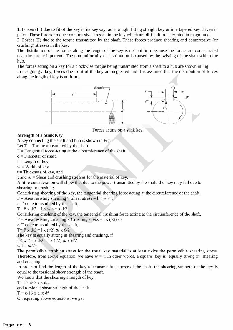
1. Forces (F1) due to fit of the key in its keyway, as in a tight fitting straight key or in a tapered key driven in
place. These forces produce compressive stresses in the key which are difficult to determine in magnitude.
2. Forces (F) due to the torque transmitted by the shaft. These forces produce shearing and compressive (or
crushing) stresses in the key.
The distribution of the forces along the length of the key is not uniform because the forces are concentrated
near the torque-input end. The non-uniformity of distribution is caused by the twisting of the shaft within the
hub.
The forces acting on a key for a clockwise torque being transmitted from a shaft to a hub are shown in Fig.
In designing a key, forces due to fit of the key are neglected and it is assumed that the distribution of forces
along the length of key is uniform.
Forces acting on a sunk key
Strength of a Sunk Key
A key connecting the shaft and hub is shown in Fig.
Let T = Torque transmitted by the shaft,
F = Tangential force acting at the circumference of the shaft,
d = Diameter of shaft,
l = Length of key,
w = Width of key.
t = Thickness of key, and
τ and σc = Shear and crushing stresses for the material of key.
A little consideration will show that due to the power transmitted by the shaft, the key may fail due to
shearing or crushing.
Considering shearing of the key, the tangential shearing force acting at the circumference of the shaft,
F = Area resisting shearing × Shear stress = l × w × τ
∴ Torque transmitted by the shaft,
T= F x d/2 = l × w × τ x d/2
Considering crushing of the key, the tangential crushing force acting at the circumference of the shaft,
F = Area resisting crushing × Crushing stress = l x (t/2) σc
∴ Torque transmitted by the shaft,
T= F x d/2 = l x (t/2) σc x d/2
The key is equally strong in shearing and crushing, if
l × w × τ x d/2 = l x (t/2) σc x d/2
w/t = σc/2τ
The permissible crushing stress for the usual key material is at least twice the permissible shearing stress.
Therefore, from above equation, we have w = t. In other words, a square key is equally strong in shearing
and crushing.
In order to find the length of the key to transmit full power of the shaft, the shearing strength of the key is
equal to the torsional shear strength of the shaft.
We know that the shearing strength of key,
T= l × w × τ x d/2
and torsional shear strength of the shaft,
T = π/16 x τ1 x d3
On equating above equations, we get

Page no: 9
l × w × τ x d/2 = π/16 x τ1 x d3
l = π/8 x (τ1 x d2)/w x τ = πd/2 x (τ1/τ) = 1.571d x (τ1/τ) ... (Taking w = d/4)
When the key material is same as that of the shaft, then τ = τ1.
∴ l = 1.571 d ... [From above equation]
Effect of Keyways
A little consideration will show that the keyway cut into the shaft reduces the load carrying capacity of the
shaft. This is due to the stress concentration near the corners of the keyway and reduction in the cross-
sectional area of the shaft. It other words, the torsional strength of the shaft is reduced. The following relation
for the weakening effect of the keyway is based on the experimental results by H.F. Moore.
e = 1 – 0.2 (w/d) – 1.1 (h/d)
where e = Shaft strength factor. It is the ratio of the strength of the shaft with keyway to the strength of the
same shaft without keyway,
w = Width of keyway,
d = Diameter of shaft, and
h = Depth of keyway = Thickness of Key (t) / 2
It is usually assumed that the strength of the keyed shaft is 75% of the solid shaft, which is somewhat higher
than the value obtained by the above relation.
In case the keyway is too long and the key is of sliding type, then the angle of twist is increased in the ratio
kθ as given by the following relation:
kθ = 1 + 0.4 (w/d) + 0.7 (h/d)
where kθ = Reduction factor for angular twist.
Shaft Coupling Shafts are usually available up to 7 meters length due to inconvenience in transport. In order to have a greater
length, it becomes necessary to join two or more pieces of the shaft by means of a coupling.
Shaft couplings are used in machinery for several purposes, the most common of which are the following:
1. To provide for the connection of shafts of units that are manufactured separately such as a motor and
generator and to provide for disconnection for repairs or alternations.
2. To provide for misalignment of the shafts or to introduce mechanical flexibility.
3. To reduce the transmission of shock loads from one shaft to another.
4. To introduce protection against overloads.
5. It should have no projecting parts.
Requirements of a Good Shaft Coupling
A good shaft coupling should have the following requirements:
1. It should be easy to connect or disconnect.
2. It should transmit the full power from one shaft to the other shaft without losses.
3. It should hold the shafts in perfect alignment.
4. It should reduce the transmission of shock loads from one shaft to another shaft.
5. It should have no projecting parts.
Types of Shafts Couplings
Shaft couplings are divided into two main groups as follows:
Rigid coupling. It is used to connect two shafts which are perfectly aligned. Following types of rigid
coupling are important from the subject point of view:
(a) Sleeve or muff coupling.
(b) Clamp or split-muff or compression coupling, and
(c) Flange coupling.
Sleeve or Muff-coupling
It is the simplest type of rigid coupling, made of cast iron. It consists of a hollow cylinder whose inner
diameter is the same as that of the shaft. It is fitted over the ends of the two shafts by means of a gib head

Page no: 10
key, as shown in Fig. 13.10. The power is transmitted from one shaft to the other shaft by means of a key and
a sleeve. It is, therefore, necessary that all the elements must be strong enough to transmit the torque. The
usual proportions of a cast iron sleeve coupling are as follows:
Outer diameter of the sleeve, D = 2d + 13 mm
And length of the sleeve, L = 3.5 d
Sleeve and muff Coupling
Clamp or Compression Coupling
It is also known as split muff coupling. In this case, the muff or sleeve is made into two halves and are
bolted together as shown in Fig. The halves of the muff are made of cast iron. The shaft ends are made to a
butt each other and a single key is fitted directly in the keyways of both the shafts. One-half of the muff is
fixed from below and the other half is placed from above. Both the halves are held together by means of mild
steel studs or bolts and nuts. The number of bolts may be two, four or six. The nuts are recessed into the
bodies of the muff castings. This coupling may be used for heavy duty and moderate speeds. The advantage
of this coupling is that the position of the shafts need not be changed for assembling or disassembling of the
coupling. The usual proportions of the muff for the clamp or compression coupling are:
Diameter of the muff or sleeve, D = 2d + 13 mm
Length of the muff or sleeve, L = 3.5 d
where d = Diameter of the shaft.
Clamp or Compression Coupling
Flange Coupling
A flange coupling usually applies to a coupling having two separate cast
mounted on the shaft end and keyed to it. The faces are turned up at right angl
iron flanges. Each flange is
to the axis of the shaft. One
of the flange has a projected portion and the other flange has a corresponding recess This helps to bring the
shafts into line and to maintain alignment.

Page no: 11
Flange Coupling
The two flanges are coupled together by means of bolts and nuts. The flange coupling is adopted to heavy
loads and hence it is used on large shafting.
keys
A key is a piece of mild steel inserted between the shaft and hub or boss of the pulley to connect these
together in order to prevent relative motion between them. It is always inserted parallel to the axis of the
shaft. Keys are used as temporary fastenings and are subjected to considerable crushing and shearing
stresses. A keyway is a slot or recess in a shaft and hub of the pulley to accommodate a key.
Types of Keys
The following types of keys are important from the subject point of view:
1. Sunk keys,
2. Saddle keys,
3. Tangent keys,
4. Round keys, and
5. Splines.
Sunk Keys
The sunk keys are provided half in the keyway of the shaft and half in the keyway of the hub or boss of the
pulley. The sunk keys are of the following types:
1. Rectangular sunk key. A rectangular sunk key is shown in Fig. The usual proportions of this key are:
Width of key, w = d / 4; and thickness of key, t = 2w / 3 = d / 6
Where d = Diameter of the shaft or diameter of the hole in the hub.
The key has taper 1 in 100 on the top side only.

Page no: 12
Fig. 2.20 Rectangular sunk key
2. Square sunk key. The only difference between a rectangular sunk key and a square sunk key is that its
width and thickness are equal, i.e.
w = t = d / 4
3. Parallel sunk key. The parallel sunk keys may be of rectangular or square section uniform in width and
thickness throughout. It may be noted that a parallel key is a taper less and is used where the pulley, gear or
other mating piece is required to slide along the shaft.
4. Gib-head key. It is a rectangular sunk key with a head at one end known as gib head. It is usually
provided to facilitate the removal of the key. A gib head key is shown in Fig. 2.21 (a) and its use is shown in
Fig. 2.21 (b).
(a) (b)
Fig. 2.21 Gib-head key
The usual proportions of the gib head key are:
Width, w = d / 4;
and thickness at large end, t = 2w / 3 = d / 6
5. Feather key. A key attached to one member of a pair and which permits relative axial movement is known
as feather key. It is a special type of parallel key which transmits a turning moment and also permits axial
movement. It is fastened either to the shaft or hub, the key is a sliding fit in the keyway of the moving piece.

Page no: 13
(a) (b)
Fig. 2.22 Feather Key
The feather key may be screwed to the shaft as shown in Fig. 2.22 (a) or it may have double gib heads as
shown in Fig. 2.22 (b). The various proportions of a feather key are same as that of rectangular sunk key and
gib head key.
The following table shows the proportions of standard parallel, tapered and gib head keys, according to IS:
2292 and 2293-1974 (Reaffirmed 1992).
Proportions of standard parallel tapered and gib head keys
a
6. Woodruff key. The woodruff key is an easily adjustable key. It is a piece from a cylindrical disc having a
segmental cross-section in front view as shown in Fig. 2.23. A woodruff key is capable of tilting in a recess
milled out in the shaft by a cutter having the same curvature as the disc from which the key is made. This key
is largely used in machine tool and automobile construction.
Fig. 2.23 Woodruff key
ft diameter (mm) up to
including
Key cross-section aft diameter (mm) up to
including
Key cross-section
Width (mm) Thickness (mm) Width (mm) Thickness (mm)
6 2 2 85 25 14
8 3 3 95 28 16
10 4 4 110 32 18
12 5 5 130 36 20
17 6 6 150 40 22
22 8 7 170 45 25
30 10 8 200 50 28
38 12 8 230 56 32
44 14 9 260 63 32
50 16 10 290 70 36
58 18 11 330 80 40
65 20 12 380 90 45
75 22 14 440 100 50

Page no: 14
The main advantages of a woodruff key are as follows:
1. It accommodates itself to any taper in the hub or boss of the mating piece.
2. It is useful on tapering shaft ends. Its extra depth in the shaft prevents any tendency to turn over in its
keyway.
The disadvantages are:
1. The depth of the keyway weakens the shaft.
2. It cannot be used as a feather.
Saddle keys
The saddle keys are of the following two types:
1. Flat saddle key, and 2. Hollow saddle key
A flat saddle key is a taper key which fits in a keyway in the hub and is flat on the shaft as shown in Fig.
2.24. It is likely to slip around the shaft under load. Therefore it is used for comparatively light loads.
A hollow saddle key is a taper key which fits in a keyway in the hub and the bottom of the key is shaped to
fit the curved surface of the shaft. Since hollow saddle
keys hold on by friction, therefore these are suitable for light loads. It is usually used as a temporary fastening
in fixing and setting eccentrics, cams etc.
Tangent Keys
The tangent keys are fitted in the pair at right angles as shown in Fig. 2.25. Each key is to withstand torsion
in one direction only. These are used in large heavy duty shafts.
Fig. 2.25 Tangent Key
Round Keys
The round keys, as shown in Fig. 2.26 (a) are circular in section and fit into holes drilled partly in the shaft
and partly in the hub. They have the advantage that their keyways may be drilled and reamed after the mating
parts have been assembled. Round keys are usually considered to be most appropriate for low power drives.
Sometimes the tapered pin, as shown in Fig. 2.26 (b) is held in place by the friction between the pin and the
reamed tapered holes.
T = w/3 = d/12
Fig. 2.24 Saddle key

Page no: 15
(a)
Fig. 2.26 Round keys
(b)
Splines
Sometimes, keys are made integral with the shaft which fits in the keyways broached in the hub. Such shafts
are known as splined shafts as shown in Fig. 2.27 These shafts usually have four, six, ten or sixteen splines.
The splined shafts are relatively stronger than shafts having a single keyway.
The splined shafts are used when the force to be transmitted is large in proportion to the size of the shaft as in
automobile transmission and sliding gear transmissions. By using splined shafts, we obtain axial movement,
as well as positive drive, is obtained.
D = 1.25d and b = 0.25D
Fig. 2.27 Splines
Forces acting on a Sunk Key
When a key is used for transmitting torque from a shaft to a rotor or hub, the following two types of forces
act on the key:
1. Forces (F1) due to fit of the key in its keyway, as in a tight-fitting straight key or in a tapered key driven in
place. These forces produce compressive stresses in the key which are difficult to determine in magnitude.
2. Forces (F) due to the torque transmitted by the shaft. These forces produce shearing and compressive (or
crushing) stresses in the key.
The distribution of the forces along the length of the key is not uniform because the forces are concentrated
near the torque-input end. The non-uniformity of distribution is caused by the twisting of the shaft within the
hub. The forces acting on a key for a clockwise torque being transmitted from a shaft to a hub are shown in
Fig. 2.28.
In designing a key, forces due to fit of the key are neglected and it is assumed that the distribution of forces
along the length of the key is uniform.

Page no: 16
Fig. 2.28 Forces acting on a sunk key
Strength of a Sunk Key
A key connecting the shaft and hub is shown in Fig. 2.28
Let T = Torque transmitted by the shaft,
F = Tangential force acting at the circumference of the shaft,
d = Diameter of the shaft,
l = Length of the key,
w = Width of the key.
t = Thickness of key, and
τ and σc = Shear and crushing stresses for the material of key.
A little consideration will show that due to the power transmitted by the shaft, the key may fail due to
shearing or crushing.
Considering shearing of the key, the tangential shearing force acting at the circumference of the shaft,
F = Area resisting shearing × Shear stress = l × w × τ
∴ Torque transmitted by the shaft,
T= F x d/2 = l × w × τ x d/2
Considering crushing of the key, the tangential crushing force acting at the circumference of the shaft,
F = Area resisting crushing × Crushing stress = l x (t/2) σc
∴ Torque transmitted by the shaft,
T= F x d/2 = l x (t/2) σc x d/2
The key is equally strong in shearing and crushing, if
l × w × τ x d/2 = l x (t/2) σc x d/2
w/t = σc/2τ
The permissible crushing stress for the usual key material is at least twice the permissible shearing stress.
Therefore from above equation, we have w = t. In other words, a square key is equally strong in shearing and
crushing.
In order to find the length of the key to transmit full power of the shaft, the shearing strength of the key is
equal to the torsional shear strength of the shaft.
We know that the shearing strength of key,
T= l × w × τ x d/2
And torsional shear strength of the shaft,
T = π/16 x τ1 x d3
On equating above equations, we get
l × w × τ x d/2 = π/16 x τ1 x d3
l = π/8 x (τ1 x d2)/w x τ = π d/2 x (τ1/τ) = 1.571d x (τ1/τ) ... (Taking w = d/4)
When the key material is same as that of the shaft, then τ = τ1.
∴ l = 1.571 d ... [From above equation]
Effect of Keyways
A little consideration will show that the keyway cut into the shaft reduces the load carrying capacity of the
shaft. This is due to the stress concentration near the corners of the keyway and reduction in the cross-

Page no: 17
sectional area of the shaft. In other words, the torsional strength of the shaft is reduced. The following
relation for the weakening effect of the keyway is based on the experimental results by H.F. Moore.
e = 1 – 0.2 (w/d) – 1.1 (h/d)
Where e = Shaft strength factor. It is the ratio of the strength of the shaft with keyway to the strength of the
same shaft without keyway,
w = Width of keyway,
d = Diameter of shaft, and
h = Depth of keyway = Thickness of Key (t) / 2
It is usually assumed that the strength of the keyed shaft is 75% of the solid shaft, which is somewhat higher
than the value obtained by the above relation.
In case the keyway is too long and the key is of sliding type, then the angle of twist is increased in the ratio
kθ as given by the following relation:
kθ = 1 + 0.4 (w/d) + 0.7 (h/d)
Where kθ = Reduction factor for an angular twist.


![Prediction of welding residual stresses using machine ... · characterise the distribution of residual stresses in structural welds [6, 7]. With the development of residual stress](https://static.fdocuments.net/doc/165x107/5fa3f63f3be93a3412525cc3/prediction-of-welding-residual-stresses-using-machine-characterise-the-distribution.jpg)