Proforma under Rule 18 CERTIFICATE OF YEARLY TEST OF ... · Ultrasonic thickness measurement -...
25
Proforma under Rule 18 CERTIFICATE OF YEARLY TEST OF SAFETY VALVE AND EXCESS FLOW VALVE (Issued under rule 18 of SMPV(U) Rules, 1981) I hereby certify that the safety valves and excess flow valves have been tested as per the particulars below and found fit for use. 1. Safety valves - i) Identification No. and Size : ii) Make : iii) a) Fitted with vessel No. in the : installation/mounted on vehicle No. b) Particulars of licence : c) Detailed address of place of : evacuation/degassing for removal of safety valve for testing d) Tested on (Date) : At (Place) : e) Observations on opening and : closing of the valve and subsequent leakage, if any iv) Observation on physical examination of the whole assembly and especially of gasket, “0” ring and spring (Replacement of gasket/”0” ring to be mentioned). v) Observation on adequacy to the valve in relation to the vessel and product. (Safety valve test to be done pneumatically or hydraulically upto the set pressure followed by Pneumatic leak test). 2. Excess flow valves - (Applicable For Mobile Vessel for Flammable/Toxic Gas) --------------------------------------------- i) Fitted with vessel described at (1) above at (Location) : ii) Make & size iii) Observation on physical : examination, operational fitness & adequacy of the size in relation to the vessel. The valves has to be opened form outside & examined for defects in structure, thruals, alignment, condition of spring etc. Contd….2/-
Transcript of Proforma under Rule 18 CERTIFICATE OF YEARLY TEST OF ... · Ultrasonic thickness measurement -...

Proforma under Rule 18
CERTIFICATE OF YEARLY TEST OF SAFETY VALVE
AND EXCESS FLOW VALVE
(Issued under rule 18 of SMPV(U) Rules, 1981)
I hereby certify that the safety valves and excess flow valves have been tested as
per the particulars below and found fit for use.
1. Safety valves -
i) Identification No. and Size :
ii) Make :
iii)
a) Fitted with vessel No. in the :
installation/mounted on
vehicle No.
b) Particulars of licence :
c) Detailed address of place of :
evacuation/degassing for
removal of safety valve for
testing
d) Tested on (Date) :
At (Place) :
e) Observations on opening and :
closing of the valve and
subsequent leakage, if any
iv) Observation on physical
examination of the whole assembly
and especially of gasket, “0” ring
and spring (Replacement of gasket/”0”
ring to be mentioned).
v) Observation on adequacy to the
valve in relation to the vessel
and product. (Safety valve test to be
done pneumatically or hydraulically
upto the set pressure followed by
Pneumatic leak test).
2. Excess flow valves - (Applicable For Mobile Vessel for
Flammable/Toxic Gas)
---------------------------------------------
i) Fitted with vessel described at
(1) above at (Location) :
ii) Make & size
iii) Observation on physical :
examination, operational fitness
& adequacy of the size in relation
to the vessel. The valves has to be
opened form outside & examined
for defects in structure, thruals,
alignment, condition of spring etc.
Contd….2/-

:: 2 ::
3. Pipe for housing SRV (Applicable for Static installation wherein
vessels are fitted with SRV having its
spring on lower side towards vessel)
------------------------------------------------------
a) Specification of pipe :
(whether seamless Schedule 40
or 80), its size and thickness.
b) Pneumatic testing of the pipe : Tested at __________ kg/cm2
(to be tested at set pressure
of SRV)
c) Date of Test :
d) Observation on physical :
condition and its fitness.
Place :- Signature :
Date :- Name & Designation :
Seal of Competent Authority :
Ref. of CCE‟s recognition :

Proforma under Rule 19 (other than sphere)
CERTIFICATE OF PERIODICAL HYDROSTATIC TEST ON
COMPRESSED GAS VESSELS OTHER THAN SPHERES
(Issued under Rule 19 of SMPV(U) Rules, 1981)
No. ___________________________ Date _______
I hereby certify that the compressed gas vessel described was examined and
subjected to hydrostatic pressure test by me ____________________________________
and was found to have passed the examination and test satisfactorily. Particulars are
given below :
1. Name & address of the occupier/owner :
2. Particulars of the licence under :
SMPV(U) Rules, 1981
3. Vessels Particulars -
i) Identification Number :
ii) Fabricator, & Year of fabrication :
iii) Third party Inspecting Agency :
iv) Design code & Pressure :
v) Fabrication Drawing number and :
Approval reference
vi) Compressed gas to be stored/ :
transported.
4. Detailed address of place of :
evacuation/degassing, etc. for
preparation of vessel
5. Visual Examination -
i) Internal :
ii) External :
(Observations on defects such as dents,
pitting, corrosion etc. to be given clearly)
6. Ultrasonic thickness measurement -
(refer ASTM-E-797/SE 797) Shell Dished end
i) Minimum thickness observed :
ii) Original Thickness :- a) Nominal plate thickness
b) Minimum calculated
Thickness (without C.A.)
c) Corrosion Allowance (CA) if any
7. Hydrotest (Pneumatic test for
cryogenic/special vessels so
permitted by CCE) particulars –
i) Date of Test :
ii) test pressure :
iii) Duration :
iv) Observation :
Contd….2/-

:: 2 ::
8. Emergency shut off valves (ROV/EFV) -
i) Particulars – Number, Location, Make & Size :
ii) Observation on operational fitness :
9. Pipe for Housing SRV & distance pipe from vessel -
(Applicable for Static installation wherein vessels are fitted with SRVs
having spring on lower side towards vessel)
SRV Housing Pipe Distance Pipe
a) Specification of pipe :
(whether seamless Schedule
40 or 80), its size and thickness.
b) Hydrotesting of pipe (kg/cm2
)
(to be tested at 1.5 times the :
design pressure of the vessel).
c) Date of Test :
d) Observation on Physical Condition
of the pipe and its fitness. :
------------------------------------------------------
Place :- Signature :
Date :- Name & Designation :
Seal of Competent authority :
Ref. of CCE‟s recognition :

Proforma No. 11-(L) under Rule, 19 ( sphere)
CERTIFICATE OF PERIODICAL INSPECTION (NDT) AND HYDROSTATIC
TEST ON HORTON SPHERE FOR HYDROCARBONS (LPG, BUTADIENE,
PROPANE) VCM, AMMONIA ETC.
(Issued under Rule 19 of SMPV(U) Rules, 1981)
No. ___________________________ Date _______
I hereby certify that the Horton Sphere described below was examined by me and
subjected to Non Destructive Tests and hydrostatic test
____________________________________ and was found to have passed the
examination and the tests satisfactorily. Particulars are given below :
1. Name & address of the occupier :
2. Particulars of the licence under :
SMPV(U) Rules, 1981
3. Vessels Particulars -
i) Identification Number :
ii) Fabricator, & Year of fabrication :
iii) Third party Inspecting Agency :
iv) Design code & Pressure :
v) Fabrication Drawing number and :
Approval reference
4. visual Examination -
i) Internal :
ii) External :
(Observations on defects such as dents,
pitting, corrosion etc. to be given clearly)
5. Ultrasonic thickness measurement -
(refer ASTM-e-797/SE 797)
(Readings are to be taken on each petal
and crown plate)
i) Minimum thickness observed :
ii) Original Thickness :- a) Nominal plate thickness
b) Minimum calculated
Thickness (without C.A.)
c) Corrosion Allowance if any
6. Wet Flurescent Magnetic Particle Test :
(Refer ASTM-E-709/ASME Sec.V)
i) Internal (100%) :
iii) External (100%) :
Contd….2/-
:: 2 ::

7. Ultrasonic flaw Detection of Welds :
(Refer ASME.Sec.V, Article 4 except
that for thickness 2” or less, calibration
blocks described in Fig. T-542.2.1 of
Article 5 shall be used) Not less than
25% of weld seams including all T. joints
middle circumferential seams, Bottom &
Crown weld scams)
8. Liquid Penetrant Test, wherever :
necessary (Refer ASTM-E-165/IS:3658)
9. Hardness Test
(Refer ASTM-E-110-Hardness to be
measured at random on circumferential/
longitudinal welds, nozzle welds, HAS
and any left over cleat weld areas)
10. Radiographic Test, wherever :
necessary (To be carried out as
supporting test for WEMPI)
11. Hydrotest particulars -
i) Date of Test :
ii) Test pressure :
iii) Duration :
iv) Observation :
12. Emergency shut off valves (ROV/EFV) -
iv) Particulars – Number, Location, Make & Size :
v) Observation on operational fitness :
Place :- Signature :
Date :- Name & Designation :
Seal of Competent authority :
Ref. of CCE‟s recognition :
NOTE :-
1. The NDT should be carried out only by persons possessing qualification of level 2
of ASNT/ISMT.
2. Results of NDT and observations may be given in separate annexures.
3. In case any repair to the sphere becomes necessary subsequent to NDT, repair
procedure developed by an approved Fabricator and endorsed by a recognized
Inspecting Agency should be submitted to Chief Controller of Explosives for
prior approval.
Contd….3/-
:: 3 ::
4. Acceptance criteria of Test reports should be as per the fabrication code

5. In case of LPG vessel with fire proof coating, the external visual examination as
per 4(ii) shall include examination of the coating and the sphere surface as per
para A of the Recommended procedure forwarded under CCE‟s letter No.
PV(Testing)Genl dated 10/11.12.92. The ultrasonic measurements and WFMP
(internal) test shall be done from inside and the external tests, at selected locations
as mentioned at paras A4 & B of the procedure, unless it is necessary to remove
the whole coating for comprehensive external testing.

Proforma under Rule, 33
CERTIFICATE OF SAFETY FOR STORAGE OF COMPRESSED GAS
(Issued under Rule 33 of SMPV(U) Rules, 1981)
Certificate No : Date :
I, Shri ______________________________________ hereby certify that the compressed
gas installation of _________________________________________________________
(full name & address of the occupier) at _______________________________________
(Village, police Station, district, State)
has been constructed in accordance with the specification and plans approved by the
Chief Controller of Explosives and the conditions of the licence in Form – III/______and
that in my opinion the installation and foundations of the aboveground/
mounded/underground pressure vessels are of such a nature and all vessels have been so
installed and secured as to ensure safety.
The particulars of the installation and examinations carried out are noted below :-
1. Vessels and fittings are as :
described in the annexure attached.
2. FIRE PROTECTION
I) WATER
No. & Location of hydrant points :
Pressure in hydrant line :
Whether hose and water throwing :
arrangement provided, particulars thereof.
Particulars of water sprinkler system :
system provided.
Capacity of static fire water :
store or equivalent arrangement.
Observations on adequacy of :
the arrangement.
II) FIRE EXTINGUISHERS.
Make :
Type :
Capacity :
3. Decanting Pump –
Make :
Specification :
Electrical Motor: Make :
HP/RPM :
Flame proof construction protection :
Contd…2/-
:: 2 ::

4. Electrical Fittings -
(Nature, Specification, Location) :
Lamps :
Switches :
Switch Gear :
Junction Boxes, etc. :
Wiring :
5. Pipelines -
Location & Length
(As per approved plans)
Make :
Specification :
Tested at pressure___on (date)______ by _______________________________
Depth at which buried (for ALDS)
Fittings in the pipeline :
Whether valves are fire safe (for ALDS)
Type and Make :
Suitability of the fitting :
6. Vapourisers -
Type (Electrical or Direct Fired :
Make :
Capacity :
Defects, if any :
Approval reference :
7. Hose pipe for decantation
Make :
Material of Construction :
Test pressure :
8.(a) Painting & External Corrosion
prevention on vessel (particulars) :
8.(b) Cathodic protection (applicable for U/G &
mounded vessel installation)
Type of cathodic protection and the :
Standard to which it conforms Agency providing cathodic protection :
Design adequacy of cathodic protection :
Details of coating and its adequacy :
Details of Galvanic isolation and its adequacy:
Details of CP monitoring box.
Contd…3/-
:: 3 ::
9. Foundation :
Nature :

Material :
Packing between tank foundation :
Name of the Third party inspection agency
appraising the design of civil structure and
fastening arrangement.
Whether the actual construction of foundation
&fastening arrangement conforms to approved
design
(applicable for U/G Vessel installations)
10 a) Fabrication Drawing :Drawing No.Approval No. & Date
b) Layout drawing :
c) Name of the operator & its approval reference no.:
d) Name of the ALDS Installer & its :
Approval reference No.
11. Earthing details :
12. Remarks, if any :
Place :- Signature :
Date :- Name & Designation :
Seal of Competent Authority
Ref. of CCE‟s recognition :

A N N E X U R E
TO SAFETY CERTIFICATE UNDER RULE 33 OF STATIC & MOBILE
PRESSURE VESSELS (UNFIRED) RULES, 1981.
A. Vessel Particulars –
Identification Number :
Fabricator‟s Name
Particular of Inspection Certificate :
Design code :
Design Pressure (kg/cm2 (g) :
Design Temperature (0C) :
Working Pressure :
Water Capacity (M3) :
Name of the gas to be stored :
Initial Hydraulic test done on _________________(date) at pressure __________
by_______________________________________________(Inspecting Agency)
Note-1(*) Subsequent Hydraulic Test (pneumatic test for cryogenic vessels) after
installation of the vessels at site on ___________ (date) at pressure _________________
by ____________________________________________ (competent Person)
Remarks on the Test :
Nature of Installation :
(whether aboveground/mounded/underground) :
Foundation : Type _____________________________________
Remarks about foundation ____________________
Behaviour during Hydraulic Test _______________
Whether the vessels is insulated _______________________________________
If so, nature of insulation _____________________________________________
B. Fittings
1. Safety Valves No.1 No.2 No.3
Identification No. and :
Manufacturing Date
Make :
Set pressure (kg/cm2
(g) :
Tested by ______________________________on _________(date)
(Competent person)
Note-2(**) Particulars of Original test by _________________________ (Inspecting
Agency at Manufacturers premises) on ________________ (date).
Discharge flow rate :
Size :
Are size & flow rate Adequate: Yes/No Yes/No
for the vessel
(if „No‟ reasons may be given) Contd…2/-
:: 2 ::

Height of vent from vessel :
& ground level.
Whether provided with : Yes/No Yes/No
shut-off valve
Pipe for Housing SRV & distance pipe from vessel
(Applicable for Static installation wherein vessels are fitted with SRVs
having spring on lower side towards vessel)
SRV Housing Pipe Distance pipe
a) Specification of pipe :
(whether seamless schedule
40 or 80) and its thickness.
b) Hydrotesting of pipe at :
pressure (kg/cm2
)
(to be tested at 1.5 times the
design pressure of the vessels).
c) Date of Test :
d) Observation on physical :
condition of the pipe and
its fitness. ------------------------------------------------------
2. Level Gauge
a) Slip tube Gauge/Magnetic :
Level Gauge
b) Maximum Level Gauge Make:
Number, Location and
Manufacturing Date.
c) Rotogauge - :
Make, Location,
Manufacturing Date
d) any other device - :
its particulars
3. Pressure gauge -
Make, Range, Date of :
Calibration whether excess Yes/No Yes/No
Flow valve provided. If yes,
Particulars, Make, Size &
Identification Number.
Contd…3/-
:: 3 ::
4. Emergency Shut Off Arrangement- No.1 No.2 No.3
Excess flow valve – Location :
Make & manufacturing Date :
Size & Closing flow rate :
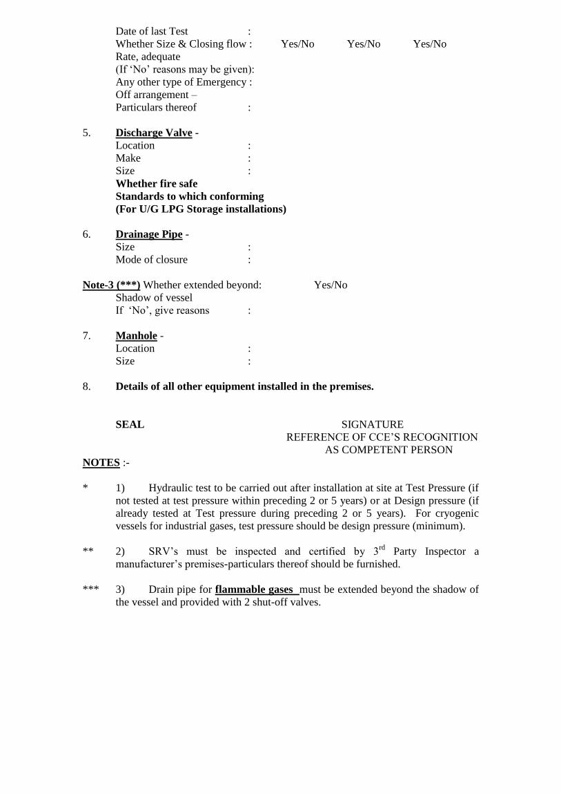
Date of last Test :
Whether Size & Closing flow : Yes/No Yes/No Yes/No
Rate, adequate
(If „No‟ reasons may be given):
Any other type of Emergency :
Off arrangement –
Particulars thereof :
5. Discharge Valve -
Location :
Make :
Size :
Whether fire safe
Standards to which conforming
(For U/G LPG Storage installations)
6. Drainage Pipe -
Size :
Mode of closure :
Note-3 (***) Whether extended beyond: Yes/No
Shadow of vessel
If „No‟, give reasons :
7. Manhole -
Location :
Size :
8. Details of all other equipment installed in the premises.
SEAL SIGNATURE
REFERENCE OF CCE‟S RECOGNITION
AS COMPETENT PERSON
NOTES :-
* 1) Hydraulic test to be carried out after installation at site at Test Pressure (if
not tested at test pressure within preceding 2 or 5 years) or at Design pressure (if
already tested at Test pressure during preceding 2 or 5 years). For cryogenic
vessels for industrial gases, test pressure should be design pressure (minimum).
** 2) SRV‟s must be inspected and certified by 3rd
Party Inspector a
manufacturer‟s premises-particulars thereof should be furnished.
*** 3) Drain pipe for flammable gases must be extended beyond the shadow of
the vessel and provided with 2 shut-off valves.
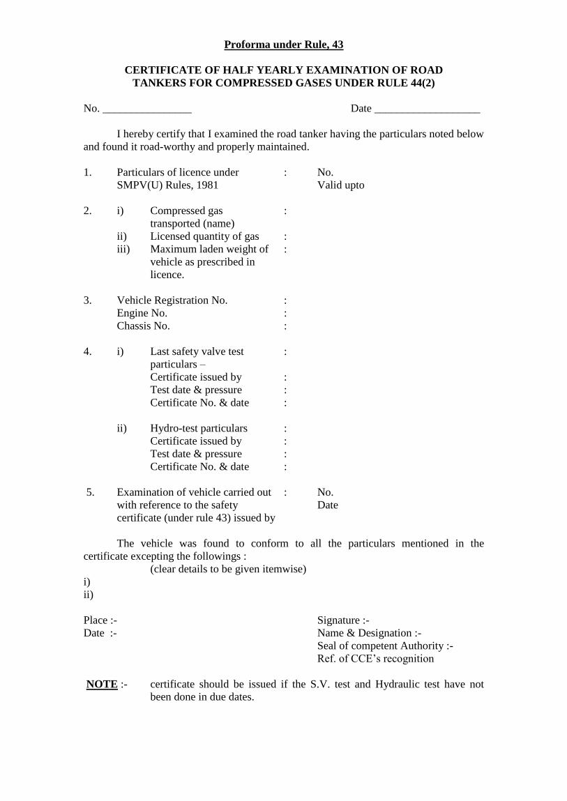
Proforma under Rule, 43
CERTIFICATE OF HALF YEARLY EXAMINATION OF ROAD
TANKERS FOR COMPRESSED GASES UNDER RULE 44(2)
No. ________________ Date ___________________
I hereby certify that I examined the road tanker having the particulars noted below
and found it road-worthy and properly maintained.
1. Particulars of licence under : No.
SMPV(U) Rules, 1981 Valid upto
2. i) Compressed gas :
transported (name)
ii) Licensed quantity of gas :
iii) Maximum laden weight of :
vehicle as prescribed in
licence.
3. Vehicle Registration No. :
Engine No. :
Chassis No. :
4. i) Last safety valve test :
particulars –
Certificate issued by :
Test date & pressure :
Certificate No. & date :
ii) Hydro-test particulars :
Certificate issued by :
Test date & pressure :
Certificate No. & date :
5. Examination of vehicle carried out : No.
with reference to the safety Date
certificate (under rule 43) issued by
The vehicle was found to conform to all the particulars mentioned in the
certificate excepting the followings :
(clear details to be given itemwise)
i)
ii)
Place :- Signature :-
Date :- Name & Designation :-
Seal of competent Authority :-
Ref. of CCE‟s recognition
NOTE :- certificate should be issued if the S.V. test and Hydraulic test have not
been done in due dates.

Proforma No. 11-(N) under Rule, 43
SAFETY CERTIFICATE UNDER RULE 43
Certificate No. Date : ____________
We hereby certify that the compressed gas transport vehicle of
_____________________________________ having the particulars noted below have
been examined by me at ______________________________ and found to meet with
the requirements of Chapter IV of SMPV(U) Rules, 1981, I also certify that the vessel its
all fittings after completion of its mounting, as per approved drawing, has been tested by
__________________________________ in my presence hydraulically at 12 kg/cm2 g
on ____________ followed by pneumatic test at 6 kg/cm2g on ______________ and
found free from any leakage.
1. No. and date of approval by CCE :-
i) Fabrication drawing No. :-
ii) Mounting drawing No. :-
2. Vehicle Particulars
i) Registration No. :
ii) Make, Model No. & Year of : Running Gear No.
iii) Engine No. : (Trailer Chassis)
iv) Chassis No. : Make :-
v) Unloden weight actual (ULW) : Ch. No. :-
vi) Maximum laden weight as : RTA Approval No.
certified by Chassis manufacturer
3. Vessel and fittings –
A. Identification Number :
Fabricator‟s Name
Particular of Inspection Certificate :
Design code :
Design Pressure (kg/cm2 (g) :
Design Temperature (0C) :
Water Capacity in litres :
Name of the gas to be stored :
Hydraulic test done on (date) at pressure by
Ultrasonic thickness measurement Shells Dish end
(Not applicable for new vessels)
i) Minimum thickness observed ______________ ____________
ii) Nominal thickness ______________ ____________
iii) Minimum Calculated thickness ______________ ____________
(without Conversion Allowance)
Contd…2/-
:: 2 ::
B. Fittings Particulars

i) Safety Valves No.1 No.2 No.3
Identification No. and :
Manufacturing Date
Make :
Set pressure in kg/cm2
:
Tested on (date)
At (pressure in kg/cm2
):
By (Competent authority):
Discharge flow rate :
Size :
Whether housed in weld caps :
If not, detail of the protection :
provided
Are size & flow rate adequate: Yes/No
(if „Not‟ reasons may be given)
Whether safety valve is
located inside vessel.
ii) Level Gauge :
a) Magnetic Level Gauge Make, :
Number & Location,
Manufacturing date
b) Maximum Level Gauge Make :
Location & depth of gauge,
Manufacturing Date.
c) Rotogauge - :
Make, Number & Location,
Manufacturing Date
iii) Pressure gauge -
Make, Range, Date of :
Calibration whether excess
Flow valve provided. If yes,
Particulars, Make
Identification Number and
Manufacturing date.
iv) Excess Flow Valves No.1 No.2 No.3
Location & Type :
Make :
Size :
Manufacturing Date :
Closing Flow rate :
Date of Last Test :
Whether size and closing :
Flow rate is adequate for (name
of the product) Service
(If „No‟ reasons may be given) Yes/No Yes/No Yes/No
Contd…3/-
:: 3 ::
v) Discharge Valve -
Location & Type :
Make & size and whether :
discharge pipe provided :

with closing device.
vi) Drainage Pipe -
Size & :
Mode of closure :
vii) Temperature gauge :
Make & range.
3. Vehicle Design Particulars :
i) Fire resisting shield :
(nature of construction)
Whether extended upto the : Yes/No
top to chessis.
Gap between driver‟s cabin :
and vessel (Min. 15 cms.)
ii) Fuel tank :
(Capacity, construction &
protection against damage)
(If the cap. Has been increased
from the original fuel tank cap,
particulars thereof)
iii) Whether transfer pump driven: Yes/No
by engine of vehicle provided
If yes, whether provision for
stopping engine from outside
made.
iv) Battery and cut-off switch : Yes/No
(Nature, capacity & location)
whether the switch is readily
accessible –
v) Particulars of wiring - :
Whether properly fixed and
Protected.
vi) Earthing points : Yes/No
(Construction & Location)
Whether strong flexible table
for electrical bonding, atleast
5m. long and with suitable
clamp/clip at each end, provided-
Contd…4/-
:: 4 ::
vii) Electrical wiring particulars :
a) How fixed with chassis & :
protected against damage
b) Whether insulated and :
fixed with the chassis

c) Whether conducted or :
protected suitably from
physical & chemical damage
d) Whether all junction boxes sealed :
e) Whether industrial type sockets :-
are provided in case of trailer
viii) Clearance between and of vessel :
and end of rear bumper (Min. 7.5 cms.)
ix) Guard railing around vessel : Yes/No
Particulars of construction whether
Railing is considered adequately strong.
x) Fastening of vessel with Chassis : Yes/No
Particulars of fastening :
i) No. of U bolts provided :
ii) Material specification :
iii) Lock Nut provided or not :
iv) Padding particulars :
v) Whether secured well to the : Yes/No
Chassis
xi) Whether chassis is extended : Yes/No
a) If yes, the length extended :
b) Nature of welding :
c) Condition of chassis and its :
fittings – whether satisfactory
in relation to safety of the vehicle.
xii) Bottom pipeline :
a) Whether pipeline between excess :
flow valve and discharge valve is
a single piece and not pieces
welded together.
Contd…5/-
:: 5 ::
b) Whether pipelines and valves :
including drainage connection
adequately secured with chassis
(give particulars) & sufficiently
away from moving parts of the vehicle
c) Mode of protection from pilferage:
xiii). Manhole -

a) Diameter :
b) Nature of protection cover over :
manhole thickness and height
xiv) Particulars of fire extinguishers :
provided
xv) Whether height barrier provided on :
the top of driver‟s
xvi) Whether the exhaust of the engine :
has been provided with spark arrestor Yes/No
If yes, Make & (CCE‟s approval No.):
5. Remarks, if any :
Place :- Signature
Date :- Full Name :-
Designation :-
Seal of Competent authority:-
Note :- Any shortcomings/deviations from the specified requirements under Static
& Mobile Pressure Vessels (Unfired) Rules, 1981 shall be high lighted
under the remarks column.
FORMAT OF CERTIFICATE OF CONTROL
“Letter-Head of the Recognized Agency”
[should indicate complete postal address of the Head office as per Approval/Recognition
letter and address of issuing branch, if inspection conducted by its branch office, having
approved Inspector(s)]

CERTIFICATE OF CONTROL
[Rule 12(2) of SMPV(U) Rules, 1981]
Certificate No : Date :
1.0 Manufacturer - ________________________________________
1.1 Fabrication shop CCE approval No. - ________________________________________
1.2 Validity of shop approval - ________________________________________
1.3 Manufactured at -
________________________________________
*Address of manufacturing unit indicating
________________________________________
place/site, Plot No./Survey No.
________________________________________
Village/ Ind. Estate, District & State
________________________________________
*In case of site fabrication or assembly
details thereof to be given. -
_____________________________________
1.4 Purchaser/for whom intended - ________________________________________
1.5 Site of installation -
_____________________________________ 1.6 Purchase order No. & Date -
________________________________________
1.7 Manufacturer‟s drawing No. -
1.______________________________________
2.______________________________________
3.______________________________________
4.______________________________________
1.8 Chief Controller of Explosives -
_______________________________________
Approval Reference of design drawing ____________ dated
______________________
1.9 Inspection Date (First) -
________________________________________
1.10 Inspection Date (Final) -
________________________________________
1.11 Type of construction - a)
Horizontal/vertical/underground/aboveground/

Mounded vessel of ________ mm dia
X _____ mm length (TL to TL or WL
to WL) with
______________________________
_dish ends
b) ____________________mm dia
Horton Sphere
1.12 Job or Vessel Identification No. -
________________________________________
2.0 Design Data
2.1 Design and construction code -
________________________________________
2.2 Name of compressed gas -
________________________________________
2.3 Water capacity (Gross/net in case of - _____________________________Ltrs.
cryogenic vessel)
2.4 Maximum allowable working pressure -
_____________________________Kg/cm2
2.5 Design Pressure - _______________________________
kg/cm2
(including _____kg/cm2 static head
+___ kg/cm2
External Load)
2.6 Operating Temperature - ________0C to ____________
0 C
2.7 Design Temperature - ________0C to ____________
0 C
2.8 Corrosion allowance - ______________________mm
2.9 Joint efficiency -
________________________________________
2.10 Radiography - Longitudinal _________%
Circumferential _________ %
T-joints _________%
Spot _________%
2.11 Post weld heat treatment -
________________________________________
2.12 Hydrotest pressure - __________________Kg/cm2
2.13 Thickness -
Shell Dish end
a) Min.
calculate
d
b)
Corrosio
n
Allowanc
e
c) Nominal
mm
mm
mm
mm
mm
mm
Note : In case of cryogenic vessel, please indicate design data of inner as well as outer vessels
3.0 Material Specification -
Item Specification Origin and T.C. No.

Main Shell
Dish ends
Flanges
Cover Flanges
Coupling
Nozzle pipe
Pad plate
Fasteners
Gaskets
Internals
Ladder support
Vessel support
*Test certificates for materials are verified and found in order.
4.0 Welding Details
4.1 WPS/PQR/WPQ - Procedure & performance test as per
__________ and found satisfactory
4.2 Names of qualified welders -
________________________________________
________________________________________
________________________________________
________________________________________
4.3 Name of CCE approved third party -
________________________________________
inspecting agency who qualified the
welders and validity of their
performance qualification.
4.4 Welding process -
________________________________________
4.5 Welding consumables -
________________________________________
4.6 Calibration Certificate, validity - -
________________________________________
& make of welding machine(s).
5.0 Inspection & Tests at Shop
5.1 Raw Materials - MTCs reviewed for
______________________
________________________________________
________________________________________
5.2 Set ups - Witnessed, checked and released prior
to
commencement of welding
5.3 Magnetic particle test -
________________________________________

________________________________________
5.4 Dye Penetrant Test -
________________________________________
________________________________________
________________________________________
5.5 Ultrasonic Flaw detection -
________________________________________
5.6 Radiography -
________________________________________
5.7 Production Control Test Results -
________________________________________
(weld test coupons)
________________________________________
________________________________________
5.8 Post weld heat treatment - Done/Not done
Full/Local stress relieving
Witnessed on _______ at _____Hrs.
_______ at _____Hrs.
(Please indicate SR witness dates &
time)
5.9 Post weld heat treatment method -
________________________________________
________________________________________
5.10 Review of heat treatment log sheets -
________________________________________
and chart
5.11 Internal and External Visual Inspection -
________________________________________
5.12 Pneumatic test of RF Pads - At ______Kg/cm2(g)
______________________
5.13 Dimensional Checks -
________________________________________
5.14 Dish end thickness measurement - Minimum observed _____ mm after
dish forming
against ____ mm minimum calculated
thickness
5.15 Workmanship -
________________________________________
5.16 Hydrostatic Test - Witnessed at ______kg/cm2 (g) for
___________
minutes on _______ and found
satisfactory.
5.17 As built drawing - Drawing
No.____________________________
Rev. _____“As Built” prepared by
manufacturer reviewed and endorsed
6.0 Method of support -
________________________________________
7.0 Internal equipment(s), if any -
________________________________________
________________________________________

8.0 Stamping on vessel -
________________________________________
8.1 Hard punch location
8.2 Manufacturer‟s Name & identification mark-
________________________________________
8.3 Client/Purchaser -
________________________________________
8.4 Purchase order No. -
________________________________________
8.5 Job No./Item No./Equipment No. -
________________________________________
8.6 Year of manufacturing -
________________________________________
8.7 Design Code -
________________________________________
8.8 Max. Allowable Pressure - _____________ kg/cm2
8.9 Design Pressure (In case of cryogenic - _____________ kg/cm2
Vessel, furnish both for inner and
outer vessels)
8.10 Design Temperature - _____________ 0C to
______________0C
8.11 Water capacity (gross) - _____________ Litres
8.12 Intended for - ________________ gas service
8.13 Gas capacity (if liquefiable gas) - ______________ Kgs.
8.14 Radiography -
________________________________________
8.15 Post weld Heat treatment - Done / Not done
8.16 Hydrotest date - ______________
8.17 Hydrotest pressure - ______________kg/cm2 (g)
8.18 Inspection by -
________________________________________
8.19 Inspecting Agency‟s stamp -
________________________________________
8.20 Certificate No. - _________________ Dated
_________________
8.21 As built drawing No. -
________________________________________
___________________________Rev._________

9.0 Conclusion : The undersigned inspectors hereby certify that the above pressure vessel is
designed, fabricated, tested and inspected during various stages of manufacture in
accordance with above said code and found fit for use for the designed service.
Issued at ______________on ___________
Signature of Inspector : _____________
Name of inspector : _____________ Monogram of
Inspecting Agency
Designation : _____________
CCE recognition : _____________
reference No. & Date
Signature of countersigning : _____________
authority
Name of countersigning : _____________
authority
Designation : _____________
CCE recognition
reference No. & Date
.