Professional Sampler TORAIZ SP-16...The Pioneer DJ site shown above offers FAQs, information on...
47
Professional Sampler TORAIZ SP-16 TSP-16 http://pioneerdj.com/support/ The Pioneer DJ site shown above offers FAQs, information on software, and various other types of information and services to allow you to use your product in greater comfort. Operating Instructions
Transcript of Professional Sampler TORAIZ SP-16...The Pioneer DJ site shown above offers FAQs, information on...

Professional Sampler
TORAIZ SP-16TSP-16
http://pioneerdj.com/support/The Pioneer DJ site shown above offers FAQs, information on software, and various other types of informationand services to allow you to use your product in greater comfort.
Operating Instructions

En2
ContentsHow to read this manual! Thank you for buying this Pioneer DJ product. Be sure to read this manual and the “Operating Instructions (Quick
Start Guide)” included with the unit. Both documents include important information that you should understand before using this product.
! In this manual, names of screens and menus displayed on the prod-uct and on the computer screen, as well as names of buttons and terminals, etc., are indicated within brackets. (e.g.: [CUE] button, [Files] panel, [MIC1] terminal)
! Please note that the screens and specifications of the software described in this manual as well as the external appearance and specifications of the hardware are currently under development and may differ from the final specifications.
! Please note that depending on the operating system version, web browser settings, etc., operation may differ from the procedures described in this manual.
Before startFeatures ....................................................................................................... 3What’s in the box ........................................................................................ 3Usable media .............................................................................................. 3About the AC adapter ................................................................................. 4
Connections and part namesConnections ................................................................................................ 5Part names and functions ......................................................................... 7
Project structure
OperationStarting the system ................................................................................... 11Loading a project ...................................................................................... 11Playing and stopping a pattern ............................................................... 11Changing the BPM ................................................................................... 11Switching the pattern ............................................................................... 12Switching the scene ................................................................................. 12Changing the length of a pattern ............................................................ 12Loading a sample to a track ..................................................................... 12Using the performance pads ................................................................... 13Using the step keys parameter adjustment knobs ................................ 14Using the touch strip function................................................................. 15Using the analog filter .............................................................................. 15Saving a project ........................................................................................ 16Quitting the system .................................................................................. 16
Overall map of graphical user interface screens
Making overall settings, adjustments, and checks (HOME)Track buttons ............................................................................................ 18Displayed contents ................................................................................... 18Fixed display area ..................................................................................... 19Parameters (HOME)................................................................................. 19Managing project files (PROJECT) .......................................................... 19Adjusting the volume of each track (MIXER) ......................................... 22Setting the output from each output terminal (OUTPUT SETTING) ... 23Creating tracks by arranging the created patterns (ARRANGER) ....... 26Changing this unit’s settings (UTILITY) ................................................. 26Setting BPM and quantize (BPM/QUANTIZE) ...................................... 27Managing scenes and patterns (SCENE MANAGER) .......................... 27
Adjusting track parameters (TRACK MENU)Module selection ...................................................................................... 30Track attribute switching button ............................................................. 31Setting the track attribute ........................................................................ 31Sample track ............................................................................................. 31Through track ............................................................................................ 40
System expansionWhen transferring samples from a PC ................................................... 41When importing sound sources from a USB device ............................. 41When synchronizing with external devices ............................................ 41
Changing the settings (UTILITY)Setting preferences .................................................................................. 42Setting the USER mode of the touch strip (TOUCH STRIP SETTING) ........................................................................ 43About the auto standby function ............................................................. 44Adjusting the touch panel (TOUCH PANEL CALIBRATION) ............... 44
Additional informationTroubleshooting ........................................................................................ 45About the liquid crystal display ............................................................... 45Cleaning the touch display ...................................................................... 45Signal flow ................................................................................................. 46About trademarks and registered trademarks ...................................... 47Cautions on copyrights ............................................................................ 47

En 3
Before start
Before start
FeaturesThis unit is a standalone hardware sampler and sequencer that allows you to intuitively compose music with a varied range of expression. It functions as a new kind of musical instrument that can also be used for live performances and DJ performances, and since a wide range of musical expression is possible with this one unit, you can use it any-where from a home studio to a stage.
Step sequencer/modulatorLarge multicolored step input keys that can be tapped while looking at the sequence information on each track and the track colors combined with six rotary encoders linked to various parameters on the display screen allow you to modify the target sound for each step and create a new groove without stopping the sound.
7-inch large touch displayThe display unit is equipped with a full-color LCD touch display. The HOME screen to view the information on the sample sound source assigned to each track with colors linked to the pads, the TRACK MENU screen to quickly grasp how to play a sound source on each track and quickly access the parameters, and the BROWSE screen to quickly browse through sample sound sources allow you to access the desired sound without hesitation by the shortest route based on the production workflow.
Performance padsThe performance pad technology and know-how acquired through the development of Pioneer DJ’s DDJ series controllers, coupled with the multicolored LEDs that can be tapped while looking at the track colors, and highly accurate velocity detection that transfers the feeling of finger-tips to the sounds, have helped to refine the expression of playing as an illuminating musical instrument.
Real-time processing engine and large capacity memoryA time stretch engine that runs for all 16 tracks in real-time, an ampli-fier envelope, effects, etc. are available, and sample sound sources can be assigned to tracks to suit applications such as loop, one shot, and SFX (effect sounds) and can easily be synchronized to the sequencer and played with high sound quality. In addition, 8 GB of flash memory is installed in the unit to allow you to create a library which allows for reliable use as a standalone device.
Analog filter in collaboration with Dave Smith InstrumentsCollaboration with a legend in the synthesizer world, Dave Smith, has been realized. A discrete analog filter circuit used in the Dave Smith Prophet-6 is employed to create a rich sound expression like real musi-cal instruments.
Accurate synchronized play function with external devices and systemsClock synchronization with MIDI-compliant devices, as well as a BEAT SYNC function1 (can be used if the firmware of the unit is updated to the latest version) in conjunction with PRO DJ LINK-compliant DJ systems, such as CDJ-2000NXS2 and XDJ-1000, enable synchronized play of tunes played by DJs with the unit at the beat and bar level.1 Operates when tracks for which the beat has been analyzed with
rekordbox TM are played by a compatible DJ system.
Other features! Support for USB storage devices which are useful for adding sound
sources and taking out projects! Pitch bend and note repeat functions, as well as “touch strip” which
allows you to customize the operation parameters! 2 GB worth of sample sound sources (from Loopmasters) that
allow you to produce and play music right away after purchase are available
What’s in the box! AC adapter! Power cord! USB cable! LAN cable! Warranty (for some regions)1
! Operating Instructions (Quick Start Guide)! Software license notice1 The warranty is included for European region only.
— For the Japanese region, the corresponding information is pro-vided on the back cover of the “Operating Instructions (Quick Start Guide)”.
— For the North American region, the corresponding information is provided on the last page of both the English and French versions of the “Operating Instructions (Quick Start Guide)”.
Usable mediaThis unit is compatible with USB mass storage class USB devices such as mobile flash memory and digital audio player.
Supported file systems
FAT16, FAT32
! Sample sound sources (wav and aiff with a sampling frequency of 44 kHz) on a USB device can be used with this unit.
! Depending on the USB device you are using, you may not achieve the expected performance.
! There is no guarantee that all USB devices will operate on this unit.
For more information, please refer to the Operating Instructions of this product published on the Pioneer DJ website.

En4
About the AC adapter
Safety instructionsTo ensure your personal safety and to maximize the full operating poten-tial of your unit, read and follow these safety instructions.
Read & Retain InstructionsRead all operating and user information provided with this product.
CleaningUse a damp cloth to clean the exterior housing. Avoid using any fluids including liquid, aerosol or alcohol-based cleaning products.
Water or MoistureAvoid operating or locating this product near water or other sources of fluid.
AccessoriesDo not place this product on an unstable cart, stand, or table. The prod-uct may fall and be seriously damaged.
VentilationDo not block or cover this product in use. This unit should not be placed in a built-in installation unless properly ventilated.
EnvironmentAvoid placing this product in a location with exposure to large quantities of dust, high temperatures, high humidity, or subject to excessive vibra-tions or shocks.
Power SourcesOperate this product only from the recommended power sources. If you are unsure of the power source, consult an authorized Pioneer representative.
Power-Cord ProtectionWhen unplugging the unit, pull on the plug – not on the cord. Do not handle the cord or plug with wet hands; doing so could cause an electric short or shock. Do not allow anything to pinch or rest on the power cord and do not place in a walkway.
PowerTurn OFF the system before installing this or any other hardware device.
OverloadingAvoid connecting too many devices to a single wall socket or power source as this can cause fires or short circuits.
Object & Liquid EntryNever push inappropriate objects in to the device. Avoid spilling any liquids in to or on the outside of the drive.
ServicingOpening or removing the cover exposes you to possible electrical shock or other danger. Contact a Pioneer authorized service representative for repairing this product (refer to the enclosed Service & Support Card).
Damage Requiring ServiceUnplug the unit and refer servicing to qualified service personnel in the following situations:! When the power cord, plug, or chassis is damaged.! If liquid has been spilled, or objects have fallen into the product.! If the product has been exposed to rain or water.! If the product does not operate normally when the operating instruc-
tions are followed. Adjust only those controls that are covered by the operating instructions. Improper adjustment of other controls may result in damage and can require extensive work by a qualified tech-nician to restore the unit to its normal operation.
! When the product exhibits a distinct change in performance – this indicates a need for service.
If there are irregularities with the AC adapter or power plug, ask your nearest Pioneer authorized service center or your dealer to carry out repair work.

En 5
Connections and
part nam
es
Connections and part namesConnectionsBe sure to turn off the power and unplug the power cord from the power outlet whenever making or changing connections.Connect the power cord after all the connections between devices have been completed.Be sure to use the power cord, AC adapter, USB cable and LAN cable included with this product.
Refer to the operating instructions for the component to be connected.
! When using a LAN cable for connection, be sure to use either the LAN cable included with this product or an STP (shielded twisted pair) cable.
! Do not disconnect the LAN cable when information is being shared using PRO DJ LINK.
Connecting the input/output terminals
� Rear panel
1 2 3 4 6 8 b5 7 9
Computer
Powered speakers
Audio I/F
External sequencer, etc.
Synthesizer, etc.
HeadphonesPRO DJ LINK compatible DJ system
a
1 Cord hookHook the AC adapters’ power cord here.! The sound will be interrupted if the AC adapter’s power cord is
disconnected from the unit during playback.
Using the cord hookHook the AC adapter’s power cord onto the cord hook to fasten it in place. This prevents the power cord from being accidentally pulled, caus-ing the plug to get disconnected from the terminal.! The sound will be interrupted if the AC adapter’s power cord is dis-
connected from the unit during playback.1 As shown on the diagram below, extend the tip of the power cord to
approximately the center of the rear panel of this unit and hook the power cord onto the bottom side of the cord hook.
2 As shown on the diagram below, move the tip of the power cord back in the opposite direction past the top of the cord hook, and hook the power cord onto the top side of the cord hook.
3 Turn the tip of the power cord so that it is facing towards you, then turn it back to create a ring as shown in the diagram and insert it into the [DC IN] terminal of this unit.

En6
2 DC IN terminalConnect the DC plug of the included AC adapter.! Connect the power cord after all the connections between
devices have been completed.! Be sure to use the included power cord.
3 u switch
4 LINK terminalConnect a PRO DJ LINK compatible device with the LAN cable (included).
5 DIN MIDI IN and DIN MIDI OUT/THRU terminalsThese are DIN type terminals. Connect another MIDI device.
6 USB-B terminalConnects to a computer.! A USB hub cannot be used.! To maintain the performance, connect this unit and computer
directly using a USB cable compliant with USB 2.0.
7 INPUT terminalsConnect a DJ player or other line level output device. When [L (MONO)] only is connected, the audio input to [L (MONO)] is also input to the [R].
8 INPUT LEVEL control
9 OUT3-8/ASSIGNABLE OUT terminals
a OUT1-2/MASTER/ASSIGNABLE OUT terminals
b Kensington security slot
c PHONES terminalsConnect headphones here.Supports a stereo phone plug (ø 6.3 mm).
Connecting USB devices
Connect the USB device to the USB device insertion slot.
Disconnecting USB devices
1 Press and hold the [USB STOP] button until the USB indicator stops flashing.Do not remove the USB device or turn Off the power of the unit while the USB indicator is flashing. The management data in the unit may get deleted. Also, the USB device may become unreadable.
USB indicator
USB STOP button
2 Disconnect the USB device.

En 7
Connections and
part nam
es
Part names and functions
Top panel
1 4 6 82 3 5 7
9
a
b
h
d
e
c
f
g
i
j
o
n m l kp
q
s
u
r
t
1 MAIN OUT controlAdjusts the volume of all outputs.Adjusts the audio level output from the [OUT1-2/MASTER/ASSIGNABLE OUT] terminals, [OUT3-8/ASSIGNABLE OUT] termi-nals, and [PHONES] terminal.
2 DRIVE controlAdjusts the drive amount of the analog filter.= Using the analog filter (p. 15 )
3 OVER indicatorLights when audio with an excessive volume level is input.
4 LOW PASS CUTOFF controlAdjusts the cutoff of the low-pass filter.= Using the analog filter (p. 15 )
5 LOW PASS RESONANCE controlAdjusts the resonance of the low-pass filter.= Using the analog filter (p. 15 )
6 HIGH PASS CUTOFF controlAdjusts the resonance of the high-pass filter.= Using the analog filter (p. 15 )
7 ACTIVE buttonTurns the analog filter on or off.= Using the analog filter (p. 15 )
8 USB STOP/WAKE UP buttonUSB STOP: If this is pressed for at least 2 seconds, the USB device becomes able to be disconnected from the unit.= Disconnecting USB devices (p. 6 )WAKE UP: Cancels the auto standby mode.= About the auto standby function (p. 44 )
9 USB device insertion slotLoad the USB device here.= Connecting USB devices (p. 6 )
a USB indicatorIt lights, flashes when this unit is communicating with the USB device.= Connecting USB devices (p. 6 )
b HOME buttonDisplays the HOME screen on the touch display.
c BACK buttonThe screen moves back to the layer above.= Operation with hardware (p. 27 )
d Rotary selectorTurning the rotary selector when selecting a project, track, setting item, etc. moves the focus. To enter the selection, press the rotary selector.
e Touch displayDisplays various information.
f Parameter adjustment knobsAdjusts the parameters corresponding to the parameter adjustment knobs.= Using the step keys parameter adjustment knobs (p. 14 )
g SCENE buttonTurns the scene switching mode on or off.= Switching the scene (p. 12 )
h PATTERN buttonTurns the pattern switching mode on or off.= Switching the pattern (p. 12 )
i Playback bar display indicatorsDisplays the bar position of the pattern being played.
j Bar selection keysSelects the bars to display for the 16 step keys.

En8
k d buttonPlays or pauses a pattern.= Playing and stopping a pattern (p. 11 )
l g buttonStops a pattern.= Playing and stopping a pattern (p. 11 )
m k buttonRecords a pad performance.= Recording a performance (dynamic recording) (p. 13 )
n SHIFT buttonWhen another button is pressed while pressing the [SHIFT] button, a different function is called out.
o 16-step keysWhen using with the pattern switching function= Switching the pattern (p. 12 )When using with the scene switching function= Switching the scene (p. 12 )When using with the step recording function= Programming triggers (step recording) (p. 14 )When using with the step modulation function= Inputing parameter changes on a step level (step modulation)
(p. 14 )
p Pad mode selection buttonSelects the operation mode of the performance pads.
q Touch stripAdjusts the effect of each mode of the touch strip.= Using the touch strip function (p. 15 )
r Performance padsWhen using with the track switching function= Switching the track (TRACK mode) (p. 13 )When using with the mute function= Muting a track (MUTE mode) (p. 13 )When using with the sample performance function= Playing a sample sound (p. 13 )When using with the slice performance function= Playing a slice performance (SLICE mode) (p. 13 )When using with the scale performance function= Playing a scale performance (SCALE mode) (p. 13 )
s HOLD buttonHolds the effect of the touch strip.= Using the touch strip function (p. 15 )
t MODE indicatorDisplays the selected touch strip mode.= Using the touch strip function (p. 15 )
u MODE buttonEach press of this switches the touch strip mode.= Using the touch strip function (p. 15 )
Rear panel
1 2
1 u switchTurns this unit’s power on and off.= Starting the system (p. 11 )
2 INPUT LEVEL controlAdjusts the level of the audio input to the [INPUT] terminals.
En 9
Connections and
part nam
esDescription of the touch display
2 3
1
4
1 Button with focusTap to move the focus. Tapping twice switches to a screen to operate the corresponding item.
2 ButtonSwitches screens and displays pop-ups.
3 Menu buttonTap to switch menus.
4 Parameter display areaOperating the parameter adjustment knobs below the display changes the values.
7
6
5
5 Touch objectTouch to enable operation of the object. Sliding your finger while it is touching the object moves the object.
6 Button with indicatorTap to switch the function on or off.The button lights or flashes when the function is on.
7 Back buttonTap to return to the screen of the level above. The same operation can be performed with the [BACK] button at the top right of the display.
8
8 ListTurning the rotary selector on the right side of the display changes the list selection position. Also, pressing the rotary selector enters the list selection.Pressing the [BACK] button cancels the selection.! Nothing can be operated by touch operation.

En10
Project structureThe data structure of this unit is as shown in the figure below.
PROJECT
SCENE
TRACK 1TRACK 2TRACK 3TRACK 4TRACK 5TRACK 6TRACK 7TRACK 8TRACK 9
TRACK 10TRACK 11TRACK 12TRACK 13TRACK 14TRACK 15TRACK 16
TRACK 1 SequenceTRACK 2 SequenceTRACK 3 SequenceTRACK 4 SequenceTRACK 5 SequenceTRACK 6 SequenceTRACK 7 SequenceTRACK 8 SequenceTRACK 9 Sequence
TRACK 10 SequenceTRACK 11 SequenceTRACK 12 SequenceTRACK 13 SequenceTRACK 14 SequenceTRACK 15 SequenceTRACK 16 Sequence
PATTERN
ARRANGEMENT
ROUTING
PROJECTA project represents one work unit for the user. Each project stores 16 scenes, one arrangement, and output routing information. This unit allows multiple projects to be created as long as internal memory space is available.
TRACKTracks consist of sample players (sample tracks only), amplifier envelope (sample tracks only), insert effects, and sequences. Two track types exist: sample tracks and through tracks.A sample track is used when setting a sample in internal memory as a sound source. A through track is used when setting an external input as a sound source.Sound sources can thus be assigned like follows: a bass drum to track 1, a snare drum to track 2, and a synthesizer connected to an external input to track 3.
SCENEScenes store 16 patterns and information on the assignments to sample tracks.Since the samples to assign to tracks can be changed for each scene, the tune can be greatly changed by changing the scene.
PATTERNA pattern combines the sequences to create in the 16 tracks and is one finished section of a performance. A pattern length can be set on a step level from a minimum of 4 steps to a maximum of 4 bars (64 steps).
ARRANGEMENTAn arrangement is created by the ARRANGER function which arranges and plays patterns in order. The playback count and BPM can be set individu-ally for each pattern. Editing of an arrangement is performed in the ARRANGER screen, and you can duplicate, paste, delete, and listen to patterns.

En 11
Op
eration
Operation
Starting the system
1 Make all the connections, then plug the power cord into a power outlet.= Connections (p. 5 )
2 Press the [u] switch on the rear panel of the unit.This unit’s indicators light up and the power turns on.
Loading a projectThe following explanations starts from the home screen. To go to the home screen, press the [HOME] button.
1 Tap [ PROJECT].The PROJECT screen appears on the touch display. In the project screen, you can perform operations such as loading and saving projects.
2 Turn the rotary selector to select [OPEN] and then press the rotary selector.The project list appears.! To return to a higher level, press the [BACK] button or tap
[ BACK] on the touch display.
3 Turn the rotary selector to select a demo project and then press the rotary selector.A confirmation pop-up appears.
4 Tap [OK].Tap [OK] to load the project.
Playing and stopping a pattern
Press the [d] button.The current pattern of the demo project plays. The [d] button is lit in green during playback.! Pressing the [d] button during playback pauses playback.! Pressing the [g] button during playback stops playback while
allowing reverberations and other sound to remain, and returns to the beginning of the pattern. Pressing the [g] button again stops all sounds including the reverberations.
Changing the BPM
1 Tap [BPM/QUANTIZE].The BPM/QUANTIZE pop-up appears.

En12
2 Set the BPM value.
The BPM value can be set in the following two ways.! Tap [TAP] at least two times with a finger in time with the quarter notes.
— The average value of the interval at which [TAP] was tapped by a finger is set as the BPM.
! Tap to select the BPM display area and then turn the rotary selector.— The BPM value is changed.— If the rotary selector is turned while pressing the [SHIFT] button,
the BPM can be set in 0.1 increments.
Switching the pattern1 Press the [PATTERN] button.The unit enters the pattern switching mode and the [PATTERN] button lights in white. The 16-step keys are lit in the current scene color during pattern switching mode.! 16 patterns can be held in one scene. Each pattern is assigned to
one of the 16-step keys.! All patterns with a sequence recorded are dimmed, all patterns
without a sequence recorded are off, and the current scene is full lit.
2 Press a 16-step key with a sequence recorded.The pattern assigned to the pressed 16-step key plays.! Pattern switching timing will be in accordance with the
PATTERN QUANTIZE setting value set in UTILITY.! The pressed 16-step key flashes during pattern switching.! Exit pattern switching mode by pressing [PATTERN] button.
Switching the scene1 Press the [SCENE] button.The unit enters the scene switching mode and the [SCENE] button lights in white. The 16 step keys are lit in the scene colors during scene switch-ing mode.! 16 scenes can be held in one project. Each scene is assigned to
one of the 16 step keys.! All patterns with a sequence recorded are dimmed, all patterns
without a sequence recorded are off, and the current scene is full lit.
2 Press a 16-step key with a sequence recorded.The scene is selected, and the unit switches to the state for selecting a pattern in that scene.! For details on switching the pattern, refer to Switching the
pattern.! Exit scene switching mode by pressing the [SCENE] button.! If the mode is exited without switching the pattern, the scene
returns to the one selected immediately before.
Changing the length of a pattern1 Press the [PATTERN] button while pressing the [SHIFT] button.The unit enters the pattern length setting mode and the [PATTERN] but-ton lights in white. The 16 step keys are lit in white and the bar selection keys are lit in blue during pattern length setting mode.! A pattern length from a minimum of 8 steps to a maximum of 64
steps can be set.
2 Press a bar selection key.Set the length of the pattern on a bar level. The bar selection keys from bar selection key [1] to the pressed bar selection key light in blue.! Pressing the [PATTERN] button ends the pattern length setting
mode.
Loading a sample to a track
1 Tap the track to which you wish to load the sample and then tap again while selected.The track menu screen appears.! You can also go to the track menu screen by turning the rotary selec-
tor to select a track and then pressing the rotary selector.
2 Tap [BROWSE].The browse screen appears. In the browse screen, you can search for samples and load samples to tracks.! You can also go to the browse screen by turning the rotary selector to
select [BROWSE] and then pressing the rotary selector.
3 Tap [FILTER TYPE] and select [FOLDER].The internal memory and USB device details are displayed in a tree on the right part of the touch display.

En 13
Op
eration4 Turn the rotary selector to select the sample you wish to load and then press the rotary selector.The sample is loaded to the track, and the name of the loaded sample is displayed at the top right of the screen.
! Press the rotary selector when a folder is selected opens or closes the folder.
! Turning the rotary selector while pressing the [SHIFT] button moves the focus on a folder basis (sample file lines are skipped).
Using the performance pads
Playing a sample sound
1 Press the [SLICE] button to turn the function off.The [SLICE] button is set to the off state.
2 Press the [SCALE] button to turn the function off.The [SCALE] button is set to the off state.
3 Hit the performance pads.The sample assigned to each performance pad plays.
Recording a performance (dynamic recording)
1 Press the [k] button.The [k] button lights in red and recording is enabled.
2 Press the [d] button.The [d] button lights in green and the sequence plays while recording is enabled.
3 Hit the performance pads to record triggers.A trigger is recorded at the timing that the pad is tapped. The step key to which the trigger was input lights or flashes in the track color.
Using the operation modes of the performance padsFour operation mode types are available.
� Switching the track (TRACK mode)
The track corresponding to a performance pad can be switched by press-ing the [TRACK] button.
1 Press the [TRACK] button.The [TRACK] button lights in white.
2 Press the performance pad corresponding to the track to which you wish to switch.The track corresponding to the pressed performance pad is set as the current track.
3 Press the [TRACK] button again.The [TRACK] button turns off and the track selection mode ends.
� Muting a track (MUTE mode)
The track corresponding to a performance pad can be muted by pressing the [MUTE] button.
1 Press the [MUTE] button.The [MUTE] button lights in white.
2 Press the performance pad corresponding to the track you wish to mute.The performance pad corresponding to the muted track turns off.! Mute can be set for multiple tracks at the same time.! To cancel mute, press the performance pad corresponding to the
muted track again.! If a performance pad is pressed while pressing the [SHIFT] button,
the corresponding tracks other than that are muted. Performing the same operation again cancels mute for all of them.
3 Press the [MUTE] button again.The [MUTE] button turns off and the mute mode ends.
� Playing a slice performance (SLICE mode)
Sliced sample sounds corresponding to performance pads can be played by pressing the [SLICE] button.
1 Select the track that has the sample for which you wish to play a slice performance assigned.= Switching the track (TRACK mode) (p. 13 )
2 Press the [SLICE] button.The [SLICE] button lights in white.! The sample is sliced equally into 16 slices and the slices are
assigned in order to the performance pads.
3 Hit the performance pads.The sample assigned to each performance pad plays.
4 Press the [SLICE] button again.The [SLICE] button turns off and the slice performance mode ends.
� Playing a scale performance (SCALE mode)
A samples of a scale corresponding to performance pads can be played by pressing the [SCALE] button.
1 Select the track that has the sample for which you wish to play a scale performance assigned.= Switching the track (TRACK mode) (p. 13 )
2 Press the [SCALE] button.The [SCALE] button lights in white.! The sample ascends by each semitone on the chromatic scale, treat-
ing the bottom left performance pad as the keynote.
3 Hit the performance pads.The sample with the scale assigned to each performance pad plays.
4 Press the [SCALE] button again.The [SCALE] button turns off and the SCALE mode ends.

En14
Using the step keys parameter adjustment knobs
Programming triggers (step recording)
1 Tap a track for step recording.The sequence of the selected track is indicated on the 16-step keys.! A track can also be selected by turning the rotary selector.! A track can also be selected by hitting a performance pad while the
[TRACK] button is in the ON state.
2 Press the 16-step keys to input triggers.The step keys corresponding to the programmed sequence lights in the track color.
Changing track parameters
1 Press the [HOME] button.The HOME screen appears.
2 Select the track that has the sample for which you wish to change the parameters assigned.= Switching the track (TRACK mode) (p. 13 )
3 Turn the parameter adjustment knobs.The parameter corresponding to each parameter adjustment knob changes. The parameter values are displayed at the bottom of the touch display.! Turn the parameter 1 adjustment knob (changes the volume). The volume of the track changes.! Turn the parameter 2 adjustment knob (changes the panning
position). The panning position of the track changes.! Turn the parameter 3 adjustment knob (changes the pitch of the
sound). The sound pitch of the track changes.! Turn the parameter 4 adjustment knob (sets the time stretch). The method of stretching a sample to synchronize the BPM is set.! Turn the parameter 5 adjustment knob (sets loop playback). Sample loop playback is switched.! Turn the parameter 6 adjustment knob (sets the sample playback
method). The method of playing of a sample in response to a trigger is
switched.! For details on the operation when each adjustment knob is turned,
refer to Making overall settings, adjustments, and checks (HOME) (p. 18 ).
Inputing parameter changes on a step level (step modulation)
1 Tap the track which you wish to change and tap again to enter.The track menu screen appears.! You can also go to the track menu screen by turning the rotary selec-
tor to select a track and then pressing the rotary selector.
2 Tap [PLAYBACK] and tap again in the selected state.The playback screen appears.! You can also go to the playback screen by turning the rotary selector
to select [PLAYBACK] and then pressing the rotary selector.
3 Turn a parameter adjustment knob while pressing the 16-step key of the step for which you wish to change the parameter.! The name of a parameter target for step modulation is red.

En 15
Op
eration
Using the touch strip function
Using PITCH
1 Press the [MODE] button to select [PITCH].[PITCH] of the [MODE] indicators lights.! Each press of the [MODE] button changes the [MODE] indicator in
the order of [PITCH] l [REPEAT] l [USER1] l [USER2] l and so on.
2 Press and hold down the performance pad that has the sample for which you wish to change the pitch assigned.The sample sound assigned to the performance pad plays.
3 Touch the touch strip to change the parameter.The pitch of the sample sound changes according to position touched on the touch strip. Also, the touch strip indicator of the position touched on the touch strip lights.! The range for changing the pitch using the touch strip is as follows. Very bottom: -2 semitones Very top: +2 semitones! Pressing a performance pad from the state of touching the touch
strip also changes the pitch.! The effect using the touch strip only operates while you continue
pressing a performance pad. It cannot be used in a sequence.
Using REPEAT
1 Press the [MODE] button to select [REPEAT].[REPEAT] of the [MODE] indicators lights.! Each press of the [MODE] button changes the [MODE] indicator in
the order of [PITCH] l [REPEAT] l [USER1] l [USER2] l and so on.
2 Press and hold down the performance pad that has the sample you wish to repeatedly play assigned.The sample sound assigned to the performance pad plays.
3 Touch the touch strip to change the parameter.The sample sound plays repeatedly according to position touched on the touch strip. Also, the touch strip indicator of the position touched on the touch strip lights.! The range for the repeat interval using the touch strip is as follows.
1/4 beat (quarter note) l 1/8 beat (eight note) l 1/16 beat (six-teenth note) l 1/32 beat (thirty-second note)
! Pressing a performance pad from the state of touching the touch strip also plays the sample sound repeatedly.
! The effect using the touch strip only operates while you continue pressing a performance pad. It cannot be used in a sequence.
4 Change the force applied to the performance pad.The sample volume changes according to the increase or decrease in force applied to the performance pad. Pressing with a stronger force increases the volume and pressing with a weaker force decreases the volume.
Using with USER setting
1 Press the [MODE] button to select [USER1] or [USER2].[USER1] or [USER2] of the [MODE] indicators lights.! Each press of the [MODE] button changes the [MODE] indicator in
the order of [PITCH] l [REPEAT] l [USER1] l [USER2] l and so on.
2 Set the parameters to be changed with [USER1] or [USER2].Configure the settings of the parameters on the TOUCH STRIP SETTING (USER1) screen or TOUCH STRIP SETTING (USER2) screen.= Switching the track (TRACK mode) (p. 13 )
3 Press and hold down the performance pad that has the sample for which you wish to change the parameter assigned.The sample sound assigned to the performance pad plays.
4 Touch the touch strip to change the parameter.The sample sound changes according to position touched on the touch strip. Also, the touch strip indicator of the position touched on the touch strip lights.! Pressing a performance pad from the state of touching the touch
strip also plays the sample sound repeatedly.! The effect using the touch strip only operates while you continue
pressing a performance pad. It cannot be used in a sequence.
Using HOLD
1 Press the [HOLD] button.The [HOLD] button lights.
2 Touch the touch strip.Hold is performed and the touch strip indicator lights at the position the touch strip was last touched.! If the mode is switched, hold is canceled and the [HOLD] button
turns off.
Using the analog filterUse the dials to sculpt your sound – manipulating Drive, Cut Off and Resonance – and add true analogue warmth and presence.
1 Press the [ACTIVE] button.The analog filter effect is enabled (activated). In the active state, the button is lit in red.
2 Turn the [LOW PASS CUTOFF] control.The low-pass filter’s cutoff frequency changes.! Turning the control counterclockwise moves the cutoff frequency
toward the lower frequencies, and turning it clockwise moves the cutoff frequency toward the higher frequencies.
3 Turn the [LOW PASS RESONANCE] control.The low-pass filter’s resonance changes.! Turning the control counterclockwise reduces the resonance of
sound in the vicinity of the cutoff frequency, and turning it increases the resonance.
4 Turn the [HIGH PASS CUTOFF] control.The high-pass filter’s cutoff frequency changes.! Turning the control counterclockwise moves the cutoff frequency
toward the lower frequencies, and turning it clockwise moves the cutoff frequency toward the higher frequencies.
5 Turn the [DRIVE] control.The analog filter’s drive amount is adjusted.! Turning the control counterclockwise reduces the effect, and turning
it clockwise increases the effect.! If the effect is made large, the output sound may be distorted. When
that happens, the OVER indicator lights in amber so that you can know that a distortion effect is occurring due to the analog filter circuit.

En16
Saving a project
1 Tap [ PROJECT].The PROJECT screen appears on the touch display. In the project screen, you can perform operations such as loading and saving projects.
2 Turn the rotary selector to select [SAVE] and then press the rotary selector.A saving window pops up. The progress is indicated by a progress bar in the pop-up screen.! When saving is completed, the pop-up windows disappears and the
project screen appears.! To change the project name and then save the project, select
[SAVE AS], enter a project name, and then save the project.
Quitting the system
Press the [u] switch on the rear panel of the unit.! Do not disconnect the USB device or turn off this unit’s power
while the USB indicator is lit or flashing. Doing so could delete this unit’s management data and damage the USB device, making it impossible to read.

En 17
Overall m
ap of g
raphical user interface screens
Overall map of graphical user interface screensTRACK MENU BROWSE
SAMPLING/EDIT
PLAYBACK
AMP ENVELOPE
FX1PROJECT
TRACK SETTING
MIXER
ARRANGER
UTILITY
SEQUENCE
MASTER/SEND FX
OUTPUT SETTING
TOUCH STRIPSETTING
TOUCHPANELCALIBLATION
HOME
SCENE MANAGERBPM/QUANTIZE
POPUP
! HOME (p. 18 )! TRACK MENU (p. 30 )! PROJECT (p. 19 )! TRACK SETTING (p. 21 )! MIXER (p. 22 )! ARRANGER (p. 26 )! UTILITY (p. 42 )! BROWSE (p. 31 )! SAMPLING/EDIT (p. 33 )! PLAYBACK (p. 35 )! AMP ENVELOPE (p. 37 )! FX1 (p. 38 )! SEQUENCE (p. 40 )! MASTER/SEND FX (p. 25 )! OUTPUT SETTING (p. 23 )! TOUCH STRIP SETTING (p. 43 )! TOUCH PANEL CALIBRATION (p. 44 )! BPM/QUANTIZE (p. 27 )! SCENE MANAGER (p. 27 )

Making overall settings, adjustments, and checks (HOME)This screen serves as the base of all screens. It allows you to check the assignment status of the performance pads and the status of each track.
Track buttons
Track selection
Selected state Unselected state
One of the tracks is always selected. Track 1 at the bottom left is selected by default.A track can be selected by tapping. Tapping the selected track again (or pressing the rotary selector) switches to the track menu screen.If you turn the rotary selector, the track selection position moves. Turn it clockwise to move the position in ascending order from track 1 to 16, and then from 16 back to 1. Turn it counterclockwise to move the posi-tion in the reverse direction.! For details on the content displayed in the track button, refer to
Displayed contents.
Displayed contents
SAMPLE track
� Display of name of assigned sample
If a sample is assigned to a track, the name of the assigned sample is displayed.If the sample name will not fit within the button, part of it is omitted and the omitted part is replaced with “...”
� ACTIVE/MUTE
If the [MUTE] is performed by pad operation, the indicators in the area indicating the track number are all grayed out.
� Track attribute
This indicates the attribute of the track that is set in the track menu.! The sound stops when the attribute is switched, so the switch is
performed not in this screen but in the track menu of each track. SMPL: SAMPLE track
This track plays a sample sound source.For details on the displayed content of a SAMPLE track, refer to Display of name of assigned sample. THRU: THROUGH track
An external input becomes the sound source, so the sample name dis-appears and the input source is displayed.
� TRIGGER MODE and LOOP
This displays the state of how the assigned sound is played.The turning on and off of LOOP has an effect both during a pad perfor-mance and during a sequence performance, but TRIGGER MODE has an effect only during a pad performance.! In the case of GATE, the sample plays only while the pad is pressed.! In the case of One Shot, the sample is triggered the instant the
performance pad is pressed, and plays only for the specified time.
LOOP TRIGGER MODE
OFF One Shot
OFF GATE
ON One Shot
ON GATE
! This can be switched with the parameter adjustment knobs at the bottom of the display.
� Status display of TIME STRETCH
This can be switched between three statuses: OFF n RSMPL (Resample) n M.TMP (Master Tempo).
En18

En 19
Making
overall settings, ad
justments, and
checks (HO
ME)
Fixed display area1 2
34567
1 Screen information displayDisplays the name of the screen currently displayed.
2 Status displayDisplays the status of the connection with an external device or the status of a sequence.
3 Menu buttonTap this to go to various screens. You can go to the following screens.! The indicator of the button for the displayed screen lights.
: TRACK SETTING: MIXER: ARRANGER: UTILITY
4 TIME displayDisplays the current playback position.The display unit is [BAR:BEAT:STEP].
5 SCENE/PATTERN buttonOpens the SCENE MANAGER pop-up.Displays the current scene number and pattern number.
6 BPM/QUANTIZE buttonOpens the BPM/QUANTIZE pop-up.Displays the current BPM value and QUANTIZE value.
7 PROJECT buttonOpens the project screen.A project can be created, loaded, saved, and deleted.
Parameters (HOME)
1 2 3 4 5 6
7
1 VOLUMESets the volume of the track.
2 PANSets the panning position of the track.
3 PITCHSets the sound pitch for during sample playback.
4 TIME STRETCHSets the method of stretching a sample to synchronize the BPM.OFF:Plays the sample in its current state without synchronizing it to the BPM. This is suitable for one shot of a drum, etc.
RESAMPLE (RESMPL):Synchronizes the sample to the BPM, but changes the pitch (variable speed playback). This is suitable for a drum loop, etc.MASTER TEMPO (M.TMP):Synchronizes the sample to the BPM, but does not change the pitch (MASTER TEMPO playback). This is suitable for a melody loop, etc. The default varies depending on the analysis result of the sample.When 1SHOT sound source: OFFWhen LOOP sound source: MASTER TEMPO
5 LOOPSwitches loop playback on/off.
6 TRIGGER MODESwitches the method of displaying a sample in response to a trigger.One Shot:When the performance pad is hit, the sample plays to the end.GATE:Plays the sample only while the performance pad is pressed.
7 MASTER level meterThe MASTER level meter is displayed on the right side of the screen.When operating [VOLUME] of each track in the touch display, adjust the volume so that the peak becomes close to 0 dB.! A peak hold display function is provided, and the detected maxi-
mum level position is displayed. After that, the indication disap-pears if an even larger signal is not detected within a certain period of time (about 500 ms).
Managing project files (PROJECT)Operations such as configuration, loading, and saving can be performed on a project level.
Creating a new project
1 Tap [ PROJECT].The PROJECT screen appears on the touch display. In the project screen, you can perform operations such as loading and saving projects.
2 Turn the rotary selector to select [CREATE NEW] and then press the rotary selector.A confirmation pop-up screen appears.
! If a new project is created without saving after an existing project has been changed, the unsaved project will be lost.

3 Tap [OK].A window will pop up asking you to name the project together with an on screen keyboard.
4 Enter the project name with the software keyboard and tap [CREATE].A new project is created and the main screen appears.
Opening a projectAn existing project can be opened.
1 Tap [ PROJECT].The PROJECT screen appears on the touch display. In the project screen, you can perform operations such as loading and saving projects.
2 Turn the rotary selector to select [OPEN] and then press the rotary selector.The project list appears.! To return to a higher level, press the [BACK] button or tap [ BACK]
on the touch display.
3 Turn the rotary selector to select a demo project and then press the rotary selector.A confirmation pop-up appears.! When a USB device is inserted, any project in the USB device is also
displayed in the same list. At that time, the USB mark is displayed on the right edge of the list.
4 Tap [OK].When [OK] is tapped, the project opens.
En20

En 21
Making
overall settings, ad
justments, and
checks (HO
ME)
Saving a project
1 Tap [ PROJECT].The PROJECT screen appears on the touch display. In the project screen, you can perform operations such as loading and saving projects.
2 Turn the rotary selector to select [SAVE] and then press the rotary selector.A saving window pops up. The progress is indicated by a progress bar in the pop-up screen.
! When saving is completed, the pop-up windows disappears and the project screen appears.
! To change the project name and then save the project, select [SAVE AS], enter a project name, and then save the project.
! If the [SAVE TO USB] button is tapped when a USB device is inserted, the project is saved to the USB device.
Deleting a project
Turn the rotary selector to select [DELETE] and then press the rotary selector.An existing project can be deleted.
Changing the settings of the entire track (TRACK SETTING)The settings of each pad can be configured.
VELOCITY[VELOCITY] of a pad can be enabled or disabled.When this is ON, the playback volume of the sound source changes according to the strength that the pad is hit.When this is OFF, the sound source plays at a fixed volume which is dependent on [VELOCITY] set in [AMP ENVELOPE].The default varies depending on the analysis result of the sample. When 1SHOT sound source: ONWhen loop sound source: OFF
CHOKEExclusive control between tracks can be set.Tracks set to the same CHOKE No. become unable to be played at the same time.! “--” (none), [1], [2], [3], [4], [5], [6], [7], or [8] can be selected.! The default is “--” (none).
PAD COLORThe track color can be set to any of 16 colors.
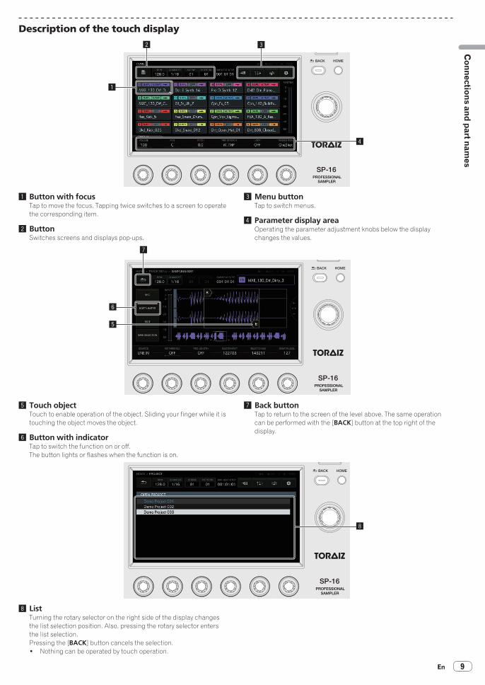
Adjusting the volume of each track (MIXER)The volume levels can be adjusted at the same time while looking at the volume levels, panning positions, and SEND amounts of multiple tracks.
The selected track has a frame.Turning the rotary selector moves the frame to change the selected track.The frame moves between tracks 1 to 16, and the selected track is linked to the selection in the HOME screen.The following elements are inside the frames of tracks 1 to 16.! PAN position! SEND amount! Level meter! Volume fader position! Track number and track color The following elements are inside the SEND and MASTER tracks.! Level meter! Volume fader position
Parameters (MIXER)The parameters of tracks 1 to 16 can be operated using [VOLUME], [PAN], and [SEND AMOUNT] at the bottom of the MIXER screen. When the numer-ical values of the parameters are set for each of the tracks, they can be reflected in the elements of the selected track as they are linked with these numerical values.Furthermore, [HEADPHONES], [SEND], and [MASTER] at the bottom of the MIXER screen are parameters that can operate the volume of the head-phones, volume of the SEND tracks, and volume of the MASTER tracks.! When the rotary selector is turned to move the focus from track to track, the [VOLUME], [PAN], and [SEND AMOUNT] parameters change as they
reflect the values set for each track. The [HEADPHONES], [SEND], and [MASTER] parameters are setting values which are common in the MIXER screen. Even when the focus is moved to another track by turning the rotary selector, they do not change.
1 2 3 4 5 6
1 VOLUMESets the volume of the track.
2 PANSets the panning position of the track.
3 SEND AMOUNTSets the send amount for SEND FX of the track.
4 HEADPHONESAdjusts the volume of headphones.
5 SEND TRACKAdjusts the volume of the SEND tracks.
6 MASTER TRACKAdjusts the volume of the MASTER tracks.
En22

En 23
Making
overall settings, ad
justments, and
checks (HO
ME)
Setting the output from each output terminal (OUTPUT SETTING)
OUTPUT SETTING screenThe output bus of each ASSIGNABLE OUT terminal, level, and output channel to send to the headphone terminal can be set.
1
2
1 ASSIGN MODE button[M + 6CH] mode: Outputs the master tracks from [OUT1-2], and also allows sending to the remaining six output terminals on an individual track level.[8CH] mode: Allows setting which of the eight output terminals to send tracks on an individual track level.1 When the list pop-up appears, turn the rotary selector to select
the mode.2 Press the rotary selector to enter the selection.
2 HP CUE buttonSelect which of the following to listen to with the headphones: [MASTER] (stereo) / [OUT1-2], [OUT3-4], [OUT5-6], [OUT7-8] (ste-reo), [1], [2], [3], [4], [5], [6], [7], [8] (monaural).! When [ASSIGN MODE] is [M + 6CH], [OUT1-2], [1], and [2] can-
not be selected.1 When the list pop-up appears, turn the rotary selector to select
the output.2 Press the rotary selector to enter the selection.
Parameters (OUTPUT SETTING)The [VOLUME], [PAN], and [OUT ASSIGN] settings of each track and the headphones output level and master level can be set.When the parameter 3 adjustment knob is turned, the output destination setting changes, and the same information is displayed at the top of the MIXER screen.! In [M + 6CH] mode, the [--] display is the default. In this state, only the master tracks output from [OUT1-2]/[MASTER] are assigned. At this time, if, for example, [OUT3-4] are specified, the assignments of the master tracks are kept as is and the audio will be output to [OUT3-4]. This allows you to output the tracks before mixing individually from different outputs while outputting the master tracks from the main speakers. [M + 6CH] mode example
1 2 3 4 5

[8CH] mode example
1 2 3 4 5
1 VOLUMESets the volume of the track.
2 PANSets the panning position of the track.
3 OUT ASSIGNSets the output destination of the track.
4 HEADPHONESAdjusts the volume of headphones.
5 MASTER TRACKAdjusts the volume of the MASTER tracks.
Other information! The SEND FX/MASTER FX effects are applied only to the master tracks.! The SEND FX/MASTER FX effects are not applied to any of the following: [OUT1-2], [OUT3-4], [OUT5-6], [OUT7-8] (stereo), [1], [2], [3], [4], [5], [6],
[7], [8] (monaural).
En24

En 25
Making
overall settings, ad
justments, and
checks (HO
ME)
Setting the send effects (MASTER/SEND FX)Initial state
SELECT FXThe SEND FX selection screen is displayed as a pop-up by the tap operation.The focus is on the effect selected for the current mode, and the effects that cannot be selected for that mode are grayed out.Turn the rotary selector to move the focus, and then press the rotary selector to enter the selection. Alternatively, you can move the focus by tapping, and then enter the selection by tapping again.When the selection is entered, the list disappears and the selected effect enters the mounted state. [Delay] and [Reverb] are in a selectable state.
Parameters (MASTER/SEND FX)MASTER/SEND FX are not target for step modulation, so the parameter changes cannot be recorded.The last setting values from the last time of use are stored for the parameters (last memory specification).

Creating tracks by arranging the created patterns (ARRANGER)
1
2
3
4
5 76
1 ARRANGEMENTPlay an arrangement.Each tap of the [ARRANGEMENT] button switches this ON/OFF. The default is OFF.ARRANGEMENT button on (ON): Plays and outputs the patterns created with the arranger.[ARRANGEMENT] button off (OFF): Plays and outputs the current pattern.! Pressing [SHIFT] + rotary selector when [ARRANGEMENT] is
ON plays from the place with the focus.
2 COPYCopies a pattern.If the focus is moved to the row of the pattern setting you wish to copy while turning the rotary selector and then the [COPY] button is tapped, the pattern setting is copied to the clipboard.
3 PASTEPastes a pattern.If the [PASTE] button is tapped, the copied pattern setting is inserted directly before the row with the focus.! Pasting is not performed by overwriting the row where the pat-
tern is pasted but always inserts a row.
4 DELETEIf the [DELETE] button is tapped, the row with the focus is deleted.
5 Arrangement display areaNo.: This is the arrangement row number.SCENE: This is the scene number.PATTERN: This is the pattern number.BPM: This is the BPM value which is set individually.
6 Playback position displayThe [d] mark is displayed at the place where the arrangement is playing.
7 Focus positionTurn the rotary selector to move the focus up and down.If the rotary selector is pressed, the current pattern is inserted directly before the row with the focus.If the parameter adjustment knobs of parameters 1 to 4 are operated with END OF ARRANGEMENT at the very bottom, a row with a pat-tern set is added automatically.If the rotary selector is turned to move the focus, the [SCENE], [PATTERN], [REPEAT], and [BPM] at the bottom are switched to the setting values of the selected row.! Pressing [SHIFT] + pressing the rotary selector plays
[ARRANGEMENT] from that row.
Parameters (ARRANGER)
1 2 3 4 5 6
1 SCENESelects the scene.Turning the pattern 1 adjustment knob changes the scene number of the row with the focus.
2 PATTERNSelects the pattern.Turning the pattern 2 adjustment knob changes the pattern number of the row with the focus.
3 REPEATSelects the number of times to play.Turning the pattern 3 adjustment knob changes the number of repeats of the row with the focus.
4 BPMSets the BPM.Turning the pattern 4 adjustment knob changes the BPM of the row with the focus.When BPM is “--,” playback is with the BPM value set immediately before.
5 HEADPHONESSets the volume of headphones.Turning the pattern 5 adjustment knob changes the HEADPHONES value.
6 MASTERSets the master volume.Turning the pattern 6 adjustment knob changes the MASTER value.
Changing this unit’s settings (UTILITY)You can check various information such as the screen contrast, per-formance pad sensitivity, unit settings, firmware version, and internal memory free space.
En26
En 27
Making
overall settings, ad
justments, and
checks (HO
ME)
Operation with hardware
Rotary selectorThe focus can be moved by turning the rotary selector.Pressing the rotary selector enters or moves between the items and selection options.
BACK buttonPressing the [BACK] button closes the screen, etc. and returns to the previous screen.When the focus is on the selection option side, pressing the [BACK] but-ton moves the focus to the item side.Pressing the rotary selector enters or moves between the items and selection options.
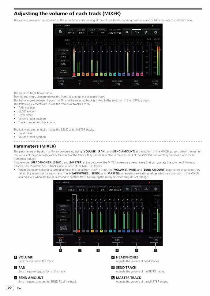
Setting BPM and quantize (BPM/QUANTIZE)BPM setting, [NUDGE], [TAP], and other operations related to playing sequences can be performed.
2 31
4
5
1 TAP buttonTapping this multiple times to match the beat sets the BPM value to match that interval.
2 BPMThis is the current BPM value of the pattern. It can be changed by turning the rotary selector.Pressing [SHIFT] + turning the rotary selector changes the fractional value.
3 SWINGThe [SWING] value can be set.
4 NUDGE buttonThe offset from a sound source for which a synchronized perfor-mance is being performed can be corrected manually by slightly advancing or delaying the BPM of the playing pattern.
5 QUANTIZE buttonQuantize values when a performance pad is hit during sequencer playback can be set.
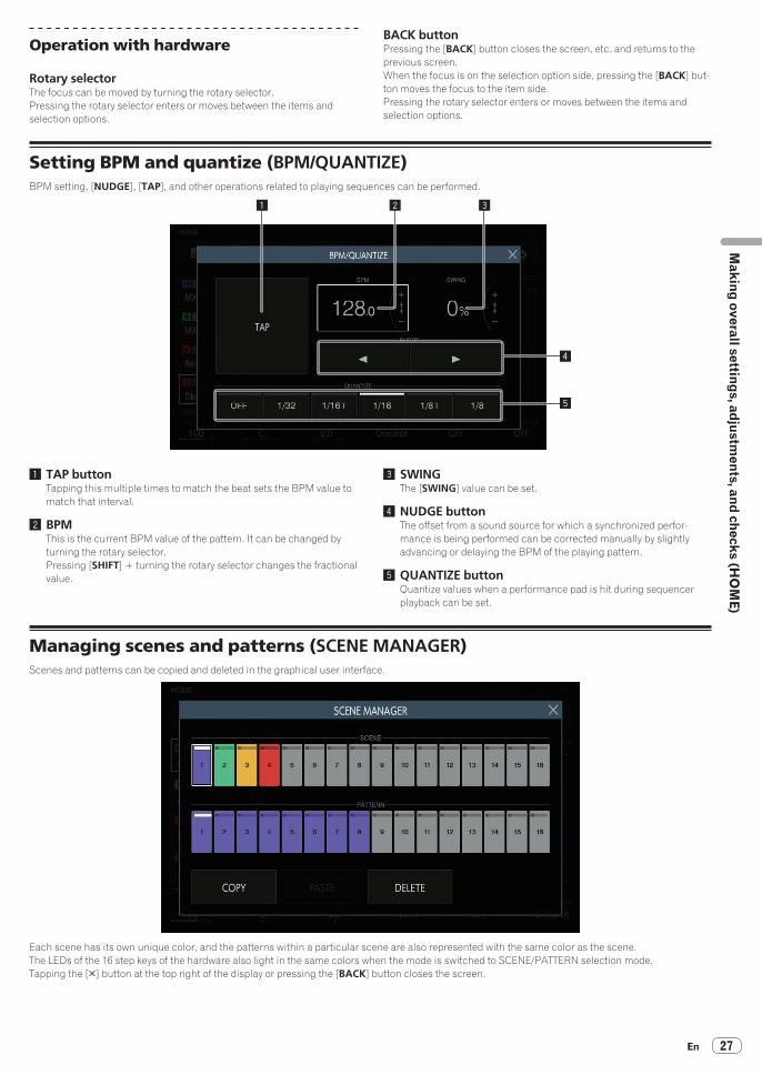
Managing scenes and patterns (SCENE MANAGER)Scenes and patterns can be copied and deleted in the graphical user interface.
Each scene has its own unique color, and the patterns within a particular scene are also represented with the same color as the scene.The LEDs of the 16 step keys of the hardware also light in the same colors when the mode is switched to SCENE/PATTERN selection mode.Tapping the [5] button at the top right of the display or pressing the [BACK] button closes the screen.

Selecting a scene and patternSelect the scene and pattern to set as the current ones.Turn the rotary selector to select a scene, and move the focus to the patterns by pressing the rotary selector. Then, turn the rotary selector to select a pattern and enter the pattern by pressing the rotary selector. The same operation can also be performed by tapping the buttons on the touch display.If the pattern is switched during playback, the switching timing will be in accordance with the PATTERN QUANTIZE setting value set in UTILITY.! If the screen is closed by touching the [5] button or pressing the [BACK] button without entering the pattern, the pattern will not be changed.
Turn the rotary selector clockwise Press the rotary selector
Scene and pattern states
Button with focus on itThis is the button on which the focus has been placed by tapping or turning the rotary selector. A white frame is displayed around the button.
Focus No focus
Current buttonThis is the button that is currently set. The indicator at the top of the button is lit in white.The indicator flashes white for the button when waiting for the pattern to change during playback.
Current Not current
Button with a sequence recordedThis is a scene button with at least one pattern recorded or a pattern button with a sequence recorded.The button is lit in the scene color.
Recording No recording
En28

En 29
Making
overall settings, ad
justments, and
checks (HO
ME)
Scene colorsThe colors set for the 16 scenes are shown in the figure below.
COPYTapping the [COPY] button copies the selected scene or pattern to the clipboard.If something is already copied to the clipboard, tapping the [COPY] button again overwrites the clipboard.! The scene or pattern that is copied has an indicator to indicate that it is copied.
PASTETapping the [PASTE] button pastes the scene or pattern that was copied to the clipboard to the selected location.The button cannot be pressed if nothing is copied to the clipboard. In that case, the [PASTE] button is grayed out. Furthermore, the [PASTE] button can also not be tapped when the focus is on a pattern while a scene is in a copied state or vice versa. In that case too, the [PASTE] button is grayed out.
DELETEA scene or pattern that has been selected by tapping can be deleted.A confirmation pop-up is displayed when deleting a scene or the pattern currently playing.

Adjusting track parameters (TRACK MENU)You can switch to the display of the selected track or each detailed setting screen.
Module selectionOne of the buttons is selected. The [BROWSE] button is selected by default.The focus is displayed on the selected button. If you tap or turn the rotary selector, the button selection position moves.! When moving the button selection position by turning the rotary button, turn it clockwise to move the position in the ascending order from
[BROWSE] to [SEQUENCE]. The position returns to [BROWSE] after [SEQUENCE]. Turn it counterclockwise to move the position in the reverse direction to clockwise.
! When the focus is on any of [PLAYBACK] to [SEQUENCE], the parameters in the corresponding detailed setting screen can be operated with the parameter adjustment knobs. When the focus is on the [BROWSE] and [SAMPLING/EDIT] buttons, the parameters and parameter flags disappears.
1 2 3 54 6
This button group is arranged to make it easy for the user to visualize the flow of sound. Furthermore, the number and types of buttons displayed here depends on the track attribute.For details on track attributes, refer to Track attribute switching button on page 31 .
1 PLAYBACKThe PLAYBACK screen can be switched to by selecting with a tap and then tapping again. Alternatively, you can switch to the screen by select-ing this with the rotary selector and then pressing the rotary selector.
2 AMP ENVELOPEThe AMP ENVELOPE screen can be switched to by selecting with a tap and then tapping again. Alternatively, you can switch to the screen by selecting this with the rotary selector and then pressing the rotary selector.The icon of ENVELOPE set in the AMP ENVELOPE screen is dis-played in a thumbnail in the button.! Even if the parameter in ENVELOPE is changed using step modu-
lation, the thumbnail image does not change.
3 FX1The FX screen can be switched to by selecting with a tap and then tapping again. Alternatively, you can switch to the screen by select-ing this with the rotary selector and then pressing the rotary selector.The icon of FX set in the FX screen is displayed in a thumbnail in the button.
4 SEQUENCEThe SEQUENCE screen can be switched to by selecting with a tap and then tapping again. Alternatively, you can switch to the screen by select-ing this with the rotary selector and then pressing the rotary selector.The status of the change of each step set in the SEQUENCE screen is displayed in a small window in the button.! The timing is changed for each step and a group is created in the
SEQUENCE screen, but when these changes are set, any step with the timing direction changed is displayed offset from the scale indication.
5 BROWSEThe BROWSE screen can be switched to by selecting with a tap and then tapping again. Alternatively, you can switch to the screen by selecting this with the rotary selector and then pressing the rotary selector.
6 SAMPLING/EDITThe SAMPLING/EDIT screen can be switched to by selecting with a tap and then tapping again. Alternatively, you can switch to the screen by selecting this with the rotary selector and then pressing the rotary selector.
En30

En 31
Ad
justing track p
arameters (TR
AC
K M
ENU
)About module displayModule buttons are highlighted while a 16-step key of a step including modulated parameters is pressed.1 The following is an example of when step modulation is performed
for [PITCH] (in PLAYBACK) and [ATTACK] (in AMP ENVELOPE).2 Press and hold a 16-step key of a step with a parameter modulated.3 The module button is highlighted and the parameter name is
enclosed with a frame while the button is held down.
Track attribute switching button
SAMPLE
This mode is for playing an audio sample or a sound source that has been sampled. If no sound source is assigned to a track, [----] is dis-played in the sample name field.If the [BROWSE] or [SAMPLING/EDIT] button is pressed and a sample is assigned in the screen of the switching destination, the sound source becomes set for the track. If you wish to further adjust the sound source itself, press the [SAMPLING/EDIT] button to switch to the EDIT screen.Each of [PLAYBACK], [AMP ENVELOPE], [FX 1], and [SEQUENCE] is a button, and a thumbnail is displayed in a small windows in the button in accordance with values set in the screen of the switching destination.
THRUINPUT MONITOR
An external input can be assigned to a track to apply an effect.Adjust the [INPUT LEVEL] control on the rear panel of the unit and the volume of the source device while looking at INPUT MONITOR. At that time, if the [SOFT LIMIT] button (ON/OFF toggle operation) is pressed, the limiter input at the input stage is enabled to reduce unnecessary clipping.
BYPASSThe track can be output by bypassing [AMP ENVELOPE] and [FX]. The default is OFF.
Setting the track attributeThe track attribute can be set.Tapping the [TRACK TYPE] button toggles between [SAMPLE] and [THRU]. There are the following two types of TRACK TYPE.1 SAMPLE TRACK2 THRU TRACK
Sample track
Selecting and loading a sample sound source (BROWSE)You can search for sound sources and assign them to tracks.

� FILTER TYPE button
Displays a list for selecting the filtering method during browsing. The display in the right column varies depending on the type selected here.
FOLDERFilters samples by folder level.1 Turn the rotary selector to move the focus. The focus can be moved on a folder bases by pressing [SHIFT] + turning the rotary selector. (The sample file lines are skipped over.)2 Pressing the rotary selector when a folder is selected opens or closes the folder.3 Select a sample file in a folder while turning the rotary selector.4 Pressing the rotary selector when a sample file is selected assigns the selected sample to the current track.
① ②
④ ③
TEXTDisplays a software keyboard so that you can search for a sound source with a character string.If you enter characters and then press the [GO] button, the search results are displayed. Only samples containing the entered character string are displayed in the list.A search is always performed within all folders.
SORTSearch results can be sorted in alphabetical ascending order and descending order. Each press of or switches between ascending order and descending order.
En32

En 33
Ad
justing track p
arameters (TR
AC
K M
ENU
) � PREVIEW button
Automatically begins a preview when a sample is selected during brows-ing. The preview status can be switched by tapping.When ON:When the rotary selector is turned to move the focus, a selected sample plays once only.When OFF:Even if the rotary selector is turned to move the focus, samples are not played.! The default is ON.! If a sample is selected when this is switched from OFF to ON, it plays
once only.
� ASSIGNED SAMPLE button
Tapping this jumps to the location of the sound source assigned to that track.! This is not displayed when [FILTER TYPE] is [TEXT].
Recording an external input sound and editing a source sound (SAMPLING/EDIT)An external or internal sound can be recorded, and the waveform of a sound source can be edited.
1 2 3 4 5 6
7
8
9
1 SOURCESelects the target for sampling.The target can be selected from [LINE IN] and [RESAMPLE].! This cannot be operated during recording.
2 REC THRESHOLDIf the input signal exceeds this value during recording standby, recording begins automatically.! This cannot be operated during recording.! The default is OFF.! OFF / -60 dB to -20 dB / PLAY
3 REC LENGTHSets the length of time to continue recording from the start of record-ing. This is dependent on the BPM of the sequencer. When the speci-fied length is reached, recording stops automatically.! This cannot be operated during recording.! The default is OFF. When OFF, recording stops automatically
when 32 seconds are exceeded after the start of recording.! OFF / 1 to 4 (BAR level)
4 SELECTION STARTSets the start point of the selection range.! This cannot be operated during recording.
5 SELECTION ENDSets the end point of the selection range.! This cannot be operated during recording.
6 MONITOR LEVELAdjusts the volume for when monitoring during recording and editing.This can be set from 0 to 127. The default is 100, which does not change the balance (track volume, panning, headphone balance, etc.) set with the mixer, etc. The relative volume can be adjusted from here.! This can also be operated during recording.
7 RECStarts input recording standby.Tapping this starts standby, and recording starts if the input signal exceeds [REC THRESHOLD].! When [REC THRESHOLD] is OFF, the state switches to recording
(lit) the moment this is tapped.
Not standby (off) Standing by (flashing) Recording (lit)
If recording is performed in the state in which a sample is already assigned, the waveform is overwritten and the sample name at the top right becomes the [RECORDED TEMP.] indication.
8 SOFT LIMITERA limiter can be applied to the input sound.! The default is OFF.

9 EDITTapping this displays the EDIT list.
a BARSets the length (number of bars) of the sample. The value of BAR varies depending on the value that is set here.
b BPMSets the BPM of the sample. The value of BPM varies depending on the value that is set here.
� SAVE CHANGES
Saves the selected range as a sample.A pop-up with a name a consecutive number entered and a software keyboard appear to enable you to assign a name.The save destination is under TORAIZ/Samples/Saved/[Project name].
1 2 3
1 CANCELClose the pop-up screen without saving anything.
2 SAVE & REPLACEAssign a name to the edited audio file, save it as a sample file, and close the pop-up. In this case, the sample assigned to the track is replaced with the saved sample.! If you wish to use the editing results immediately, select [SAVE & REPLACE].
3 SAVEAssign a name to the edited audio file, save it as a sample file, and close the pop-up. In this case, the sample assigned to the track remains.! If you wish to chop multiple samples from the same sample and then save them, select [SAVE].
En34

En 35
Ad
justing track p
arameters (TR
AC
K M
ENU
)Setting the playback method of the sample sound source (PLAYBACK)The playback method of the sound source assigned to the track can be set.
1 2 3 4 5
1 PITCHSets the sound pitch for during sample playback.The default is 0.The setting range varies depending on the TIME STRETCH mode.! When OFF: -24 to 0 to +24! RESMPL: [PITCH] is disabled, and depends on BPM.! M.TMP: -12 to 0 to +12
2 STARTSets the start point of the sample playback range. The unit varies depending on whether [GRID SNAP] is ON or OFF.! When GRID SNAP is ON: GRID number 1 to XXX (The default is 1.)! When GRID SNAP is OFF: Number of Sample (The default is 0.)
3 LOOP STARTWhen loop playback is ON, the loop start point can be set. This can be set only between [START] and [END].The unit varies depending on whether [GRID SNAP] is ON or OFF.! When GRID SNAP is ON: GRID number 1 to XXX (The default is
the same value as [START].)! When GRID SNAP is OFF: Number of Sample (The default is the
same value as [START].)
4 LENGTHSets the length of the sample playback range.The unit is the number of Sample. (The default is the same value as the length of the assigned sample.)
5 LOOPSwitches sample loop playback.! When ON: When the playback position reaches [END], playback starts
again from the position of [LOOP START] set in the same screen.! When OFF: When the playback position reaches [END], playback
ends at the same time.
� Waveform display area
Display rangeThe waveform can be enlarged or reduced by turning the rotary selec-tor. Furthermore, the waveform can be enlarged or reduced vertically by pressing [SHIFT] + turning the rotary selector.When the waveform is expanded or reduced in the time axis direction, it is expanded or reduced with the position of one of START/LOOP START/END described later as the center.
Press SHIFT
1 2 3 4 2
5
1 SLICE GRIDSLICE GRID is visible on the background.
2 START/END POINTThe range that is played when a performance pad is hit can be set.
3 Playback positionDisplays the current playback position.
4 LOOP START POINTThe range that is played repeatedly when TRIGGER MODE of the track is [LOOP One Shot] or [LOOP GATE] can be set.The loop range is highlighted.
5 START/LOOP START/END cursorsWhen [GRID SNAP] is ON, the range snaps to the GRID.The playback range can be finely set with the parameter adjustment knobs.

� Overall waveform display area
Displays the overall waveform of the assigned sample. The playback range is enclosed in a frame and the loop range is highlighted.
When the area is zoomed in and tapped, the display position jumps to the tapped place.
1 Turn the rotary selector to zoom in.The waveform is enlarged.
2 Tap the left side of the overall waveform (red part).
The display range moves.
� GRID SNAP button
When [GRID SNAP] is enabled, the position of [START], [END], etc. can be set using the GRID position unit specified in [SET SLICE]. When [GRID SNAP] is OFF, the GRID appears thin.
When [GRID SNAP] is ON, the GRID appears thick.
� REVERSE button
Reverse playback can be switched.When this is ON, the playback direction becomes reverse.
Tap [REVERSE].Reverse playback is performed.
En36

En 37
Ad
justing track p
arameters (TR
AC
K M
ENU
)Adjusting the change in volume for sample sound source playback (AMP ENVELOPE)The change in volume can be set for a sample that is played when a performance pad is hit, a sequence is played, or a trigger received.
1 2 3 54
7
6
1 VELOCITYSets the maximum value of the sample playback volume.
2 ATTACKSets the time from when an on trigger is received to when the volume level becomes the maximum (HOLD is reached).The default is 0. The minimum value is 0 and the maximum value is 32 seconds.
3 HOLDSets the time from when an on trigger is received to when the volume begins to be attenuated (RELEASE is reached).The default is [INFINITY].

4 RELEASESets the time from when HOLD is passed to when the volume level becomes 0.The minimum value is 0. The maximum value is 127. When the parameter 4 adjustment knob is turned clockwise even further from the maximum value, the value becomes [INFINITY].The default is 0.
5 TRIGGER MODEHow the envelope operates in response to a trigger can be set. This can be selected from the two options [One Shot] and [GATE].One Shot:[A] l [H] l [R] are passed with the on trigger, regardless of the length of time that the performance pad is pressed.GATE:[A] l [H] l [R] are passed while the performance pad is pressed. When [H] is [INFINITY], moves to [R] with the off trigger.This is suitable for synthesizer sound and other sound that is sustained.
6 SETTINGThe AMP ENVELOPE settings can be changed.[Attack Curve]:The curve of ATTACK can be changed. It can be switched to [Linear] or [Curve].[Release Curve]:The curve of RELEASE can be changed. It can be switched to [Linear] or [Curve].
7 SYNCWhether or not to link the operation of ENVELOPE with the BPM can be set.The default is OFF.
Applying effects to tracks (FX1)Effects can be inserted in tracks.
SELECT FX buttonTapping the [SELECT FX] button displays the FX list.Turn the rotary to select and then press the rotary selector to enter the selection.
En38

En 39
Ad
justing track p
arameters (TR
AC
K M
ENU
) � Effect display panel
This is a panel for visualizing the replacement of the DAW plugin. The controls of each FX are displayed in this panel.
1
1 ON/OFF buttonThis operates with the same rules as a normal mode selector switch.When, for example, BPM synchronization is turned ON/OFF, the track specific parameters are switched. It is lit in the ON state.
� About included FX
For the included FX and their parameters, refer to Display of name of assigned sample on page 18 .
� Parameters (AMP ENVELOPE)
The parameters of INSERT FX can be recorded because they are all step modulation targets.
� FX icon list
CHORUS FLANGER DELAY REVERB

Adjusting various trigger sequences (SEQUENCE)The trigger sequence of each track can be offset and otherwise adjusted with a smaller unit than steps.
2 3 4 5 6 7
1
1 Trigger type selection buttonsSelects the type of triggers to input.The default is [FULL].
1 Full trigger (FULL) SAMPLE, ENVELOPE, and all modulated parameters are
triggered.2 Half trigger (HALF) ENVELOPE and modulated parameters are triggered.3 Parameter trigger (PARAM) Only modulated parameters are triggered.
2 OFF SETA trigger can be finely adjusted forward or backward. It can be adjusted up to ±1 step (indicating line directly below adjacent step).Move the trigger position [b] in the graphical user interface a very small amount by manipulating this parameter.! The default is 0.
3 RETRIGGER CNTSet the number of times to input triggers repeatedly over a short period.! The default is 1.! When [RETRIGGER CNT] is two or more, the [b] mark on the
screen is changed to the mark for indicating repeated input (two [b] arranged vertically).
4 RETRIGGER SPDSets the speed for re-triggering.! The default is 1/4 (step).! When [RETRIGGER CNT] is two or more, the [b] mark on the
screen is changed to the mark for indicating repeated input (two [b] arranged vertically).
5 SHIFTAn input trigger can be offset on a step level (circle shift) within the range set in [SHIFT AREA].
6 SHIFT AREASets the range to apply [SHIFT].This can be selected from the two types [BAR] and [ALL].! Specify the operation target step with the hardware buttons.
When no step has been specified, all steps become targets. For example, all steps are uniformly offset in the case of an offset.
When an individual step is selected by pressing a step key, the corresponding vertically long [g] and [b] in the graphical user interface flash.
7 BAR buttonThis is linked to the bar selection button and the bar to display can be selected. Furthermore, the indicator of the currently displayed bar is combined.
Through trackThe [LINE IN] external input can be assigned to a track to apply an effect.Select the input source with the parameter adjustment knobs below the display and adjust [INPUT LEVEL] on the rear of the unit or the volume level of the source device while looking at the [INPUT MONITOR].At that time, if the [SOFT LIMIT] button (ON/OFF toggle operation) is pressed, the analog limiter input at the input stage is enabled to reduce unnecessary clipping.
En40

En 41
System
expansion
System expansion
When transferring samples from a PCConnect the USB port on this unit to a computer and switch to [USB MASS STORAGE MODE] in [UTILITY]. The built-in flash memory of this unit becomes able to be operated from the computer.! When disconnecting the connection, perform the disconnect opera-
tion from the computer and then disconnect the connection as described in the pop-up menu.
! Do not disconnect the cable or turn off the power of this unit during communication with the computer. The data managed on this unit may be deleted.
Computer
USB cable
When importing sound sources from a USB deviceWhen a USB device is inserted into this unit, the [TORAIZ] folder is cre-ated automatically. Only sound sources placed in the [Samples] folder in this [TORAIZ] folder can be read by the BROWSE function (p. 31 ).
USB devices
When synchronizing with external devices
Audio cable Audio cable
LAN cableMIDI cable
PRO DJ LINK compatible DJ systemSynthesizer, etc.

En42
Changing the settings (UTILITY)If you tap , the UTILITY screen appears so that you can configure vari-ous settings of this unit.
1 Tap [ UTILITY].The UTILITY screen appears.! The UTILITY screen can be displayed with the [SHIFT] button
+ [HOME] button.
2 Turn the rotary selector to select the item you wish to set.The focus moves.
3 Press the rotary selector to enter the setting value change state.The focus moves to the setting value.
4 Turn the rotary selector to change the setting value.
5 Press the rotary selector to enter the setting value.The focus moves to the setting item.! If the [BACK] button is pressed during the process, the setting value
will not be changed.
Setting preferencesOptions settings Setting ranges Descriptions
GLOBAL SETTING
TOUCH STRIP SETTING (USER1) -
Configure the settings of touch strip mode [USER1].= Setting the USER mode of the touch strip
(TOUCH STRIP SETTING) (p. 43 )
TOUCH STRIP SETTING (USER2) -
Configure the settings of touch strip mode [USER2].= Setting the USER mode of the touch strip
(TOUCH STRIP SETTING) (p. 43 )
PAD CURVE Hard 3 to Linear* to Soft 3Set the volume curve characteristics (velocity curve) in response to the strength that a pad is pressed.
PAD THRESHOLD 1 to 16Set the strength at which to press a pad to start outputting sound.
PAD SENCITIVITY 1 to 16Set the strength at which to press a pad to output at the maximum volume level.
PAD MODE SELECT RESPONSE IMMEDIATELY*, OVER 1sec.Set the switching method for when the pad mode selection button is pressed.
PATTERN QUANTIZE STEP, BAR, PATTERN*Set the timing for switching when a pattern is switched.
SYNCINTERNAL w/USB MIDI OUT*, INTERNAL w/DIN MIDI OUT, USB MIDI, PRO DJ LINK
Set the path for SYNCing with this unit.
LCD BRIGHTNESS 1, 2, 3*, 4, 5 Set the brightness of the touch display.
SCREEN SAVER OFF, ON*
When this is set to [ON], the screen saver starts if the stopped state, paused state, or the state of no operation being performed continues for at least 5 minutes.
AUTO STANDBY OFF, ON* = About the auto standby function (p. 44 )
USB MASS STORAGE MODE - = When transferring samples from a PC (p. 41 )
TOUCH PANEL CALIBRATION -= Adjusting the touch panel (TOUCH PANEL
CALIBRATION) (p. 44 )
CHARACTER PRIORITYDefault*, Chinese(simplified characters), Chinese(traditional characters), Korean
Set the display language to which to give priority on this unit.
INFORMATIONS
Version No. - Displays this unit’s software version.
DISK SPACE -Displays the amount of free space in the built-in flash memory of this unit.
! *: Setting upon purchase

En 43
Chang
ing the setting
s (UTILITY
)
Setting the USER mode of the touch strip (TOUCH STRIP SETTING)Assign the parameters to operate with USER1 and USER2 of the touch strip.
Initial stateIf the rotary selector is turned, the focus moves and the assignment place can be selected.
AssigningIf the rotary selector is pressed, a parameter selection pop-up appears.
If the parameter to assign is selected with the rotary selector and then the rotary selector is pressed, the parameter is assigned.The assigned parameter is displayed.
When this procedure is repeated in the same way to assign multiple parameters, the parameter names are added to the list.
When the touch strip is touched, the parameters change in accordance with the custom set values.! Up to eight parameters can be assigned.
CustomizingThe [BOTTOM VALUE] value for the bottom and the [TOP VALUE] value for the top of the touch strip can be set using the parameter adjustment knobs.The setting value for each assigned parameter can be set, and the value of the place with the focus on it is displayed.
DeletingIf the [DELETE] button is tapped while the focus is on a parameter to be deleted, the confirmation dialog box appears.
If [OK] is tapped, the assignment is deleted.

En44
ParameterThe parameters that can be assigned are as follows.
PLAYBACK AMP ENVELOPE FX1 SEQUENCE
PITCH VELOCITY CHORUS RATE RETRIGGER CNT
ATTACK CHORUS WIDTH RETRIGGER SPD
HOLD CHORUS PHASE
RELEASE CHORUS DELAY
CHORUS MIXRATIO
FLANGER RATE
FLANGER WIDTH
FLANGER PHASE
FLANGER DELAY
FLANGER FEEDBACK
FLANGER MIXRATIO
About the auto standby functionWhen the auto standby function is turned on, the power is automatically set to the standby mode after four hours have passed with all of the fol-lowing conditions met.— That none of this unit’s buttons or controls are operated.— The track level indicators are not lit.— The playback function is not operating.— That no PRO DJ LINK connections are made.— That no USB device is connected to the USB device insertion slot
(Type A terminal) on the unit’s top panel.— That not in USB MASS STORAGE MODE.! The indicator of the [USB STOP/WAKE UP] button is lit during auto
standby.! When the [USB STOP/WAKE UP] button is pressed, the standby
mode is canceled.! This unit is shipped with the auto standby function turned on. If you
do not want to use the auto standby function, set [AUTO STANDBY] to [OFF].
Adjusting the touch panel (TOUCH PANEL CALIBRATION)This function is for making adjustments when the touch panel of this unit is not working properly.Tap [ UTILITY] in advance to display the UTILITY screen.! The UTILITY screen can be displayed with the [SHIFT] button + [HOME] button. Press the cross marks on the screen in the order of top left l top right l bottom left l bottom right.When adjustment is finished, close the TOUCH PANEL CALIBRATION screen.
① ②
④ ③

En 45
Ad
ditional inform
ation
Additional information
Troubleshooting! Incorrect operation is often mistaken for trouble or malfunction. If you think that there is something wrong with this component, check the points
below and the [FAQ] for the [TSP-16] on the Pioneer DJ support site. http://www.pioneerdj.com/ Sometimes the problem may lie in another component. Inspect the other components and electrical appliances being used. If the problem cannot
be rectified, ask your nearest service center or your dealer to carry out repair work.! The unit may not operate properly due to static electricity or other external influences. If this happens, normal operation can be sometimes restored
by removing the power cord after turning the power off, and turning the power back on after inserting the power cord into the power outlet.
Problem Check Remedy
The power is not turned on.None of the indicators light.
Is the power cord properly connected? Plug in the power cord to an AC outlet. (page 5 )
Connect the power cord to the included AC adapter properly.Connect the DC plug of the included AC adapter to the unit properly.
Is the [u] switch of the power on the rear panel of the unit on?
Turn the [u] switch of the power on.
No sound or small sound. Are the [MAIN OUT] control on the top panel and the various parameter volumes in the graphi-cal user interface set to the proper positions or values?
Adjust the [MAIN OUT] control on the top panel and the various parameter volumes in the graphical user interface to appropriate positions or values.
In the case of an external sound source, is the [INPUT LEVEL] control on the rear panel of the unit set to the proper position?Is the output level of the external sound source input device too low?
Adjust the [INPUT LEVEL] control on the rear panel of the unit or the output level of the external sound source input device while referring to INPUT MONITOR.
Distorted sound. Are the various parameter volumes in the graphi-cal user interface set to the proper positions?
Adjust the various parameter volumes in the graphical user interface to appro-priate levels so that the peak level of the master level meter lights near 0 dB.
Is the [INPUT LEVEL] control set to the proper position?Is the output level of the external sound source input device too high?
Adjust the [INPUT LEVEL] control on the rear panel of the unit or the output level of the external sound source input device while referring to INPUT MONITOR.
USB device is not recognized. Is the USB device properly connected? Connect the device securely (all the way in).
Is the USB device connected via a USB hub? USB hubs cannot be used.
Is the USB device supported by this unit? This unit supports such USB mass storage class USB devices as external hard disks and portable flash memory devices.
Is the file format supported by this unit? Check that the file format of the connected USB device is supported on the unit.
— Turn the power off, wait 1 minute, then turn the power back on.
Time is required to read USB devices (flash memory drives and hard discs).
Is there a large number of folders or files recorded on the USB device?
When there are many folders or files, some time may be required for loading.
Are files other than music files stored on the USB device?
When files other than music files are stored in folders, time is required to read them as well. Do not store files or folders other than music files on the USB device.
File cannot be played. Is the file copyright-protected (by DRM)? Copyright-protected files cannot be played.
Music files cannot be played. Are the music files damaged? Play music files that are not damaged.
There is no response when you touch the screen, or the response is bad. A position different from the actually touched location responds.
Calibration adjustment of touch display is deviating.
Adjust the touch display by using the [TOUCH PANEL CALIBRATION] settings in the [UTILITY] screen.
Nothing is displayed. Is the auto standby function activated? This unit is shipped with the auto standby function set to on. If you do not want to use the auto standby function, set [AUTO STANDBY] on the [UTILITY] menu to [OFF]. (page 44 )
About the liquid crystal display! Small black or shining points may appear on the liquid crystal display. This is a phenomenon inherent to liquid crystal displays; this is not a
malfunction.! When using in cold places, the liquid crystal display may be dark for a while after this unit’s power is turned on. It will reach the normal brightness
after a while.! When the liquid crystal display is exposed to direct sunlight, the light will reflect off it, making it difficult to see. Block the direct sunlight.
Cleaning the touch displayDo not use organic solvents, acids or alkalis for cleaning the surface of the touch display. Wipe with a dry soft cloth or a cloth immersed in neutral detergent and squeezed properly.
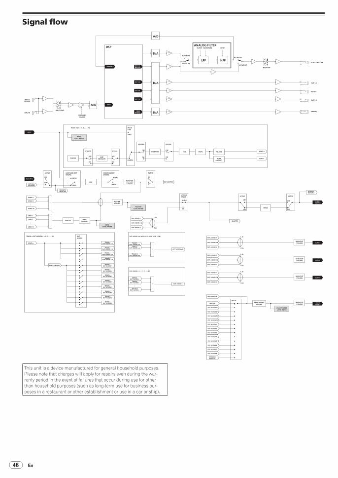
En46
Signal flow
INPUT L(MONO)
INPUT R
A/D INPUT
DSP
RESAMPLE OUT 1-2MASTER
HEADPHONES
OUT 3-4
OUT 5-6
OUT 7-8
SOFT LIMITON/OFF
INPUT LEVEL
D/A
D/A
D/A
A/D
ACTIVE ON
ACTIVE OFF
LPF HPFACTIVE ON
CUTOFF RESONANCE CUTOFF
ANALOG FILTER
OUT 1-2/MASTER
ACTIVE OFF
MAIN OUT
OUT 3-4
OUT 5-6
OUT 7-8
PHONES
OUT 3-4
HEADPHONES
OUT 5-6
OUT 7-8
OUT 1-2MASTER
SAMPLING/EDITSOURCE
OUTASSIGN
SAMPLING/EDITSOURCE
LINE IN
LINE IN
DRIVE
MASTERVOLUME
SEND FX SENDVOLUME
TRACK n [ n = 1 , 2 , ... , 16]
TRACK n OUT ASSIGN[ n = 1 , 2 , ... , 16]
INSERT FX1 PAN MUTE VOLUME
SENDAMOUNT
AMPENVELOPEPLAYER
INPUTLEVEL METER
MASTERLEVEL METER
SENDLEVEL METER
MONITORVOLUME
RSMPL
RSMPLON
OFF
ACTIVE
ON
OFF
L ch
R ch
8ch
M+6ch
OFF
ACTIVE
ON
OFF
ACTIVE
ON
OFF
ACTIVEASSIGNMODE
ON
BYPASS
OFF
ON
OFF
ON
BYPASS OFF
ON
BYPASSBYPASS
THRU
SAMPLE
TRACKTYPE
INPUT
RESAMPLE
INTERNAL
MIXER 1
MIXER 2+
・・
MIXER 16
SEND 1
SEND 2
SEND 16
+
+
TRACK nOUT ASSIGN 1-2
OUT ASSIGN a-bTRACK n
OUT ASSIGN 3-4
TRACK nOUT ASSIGN 5-6
TRACK nOUT ASSIGN 7-8
TRACK nOUT ASSIGN 1
TRACK nOUT ASSIGN 2
TRACK nOUT ASSIGN 3
TRACK nOUT ASSIGN 4
TRACK nOUT ASSIGN 5
TRACK nOUT ASSIGN 6
TRACK nOUT ASSIGN 7
TRACK nOUT ASSIGN 8
MIXER n
MIXER n MONO
L ch
R ch
OUT ASSIGN 3
REC MONITOR
OUT ASSIGN 4
OUT ASSIGN 3-4
OUT ASSIGN 1
OUT ASSIGN 2
OUT ASSIGN 1-2
OUT ASSIGN a-b[ (a,b) = (1,2) , (3,4) , (5,6) , (7,8) ]
RESAMPLE
RESAMPEMONITOR
REC MONITOR
MASTER
INTERNALRESAMPLE
MIXER n
SEND n
TRACK1OUT ASSIGN a-b
TRACK2OUT ASSIGN a-b
TRACK16OUT ASSIGN a-b
+ OUT ASSIGN c
OUT ASSIGN c [ c = 1 , 2 , ... , 8 ]
TRACK1OUT ASSIGN c
TRACK2OUT ASSIGN c
TRACK16OUT ASSIGN c
MAIN OUTVOLUME
MAIN OUTVOLUME
L ch
R ch
OUT ASSIGN 5
OUT ASSIGN 6
OUT ASSIGN 5-6MAIN OUTVOLUME
L ch
R ch
OUT ASSIGN 7
OUT ASSIGN 8
MASTER
HP CUE
OUT ASSIGN 1-2
OUT ASSIGN 3-4
OUT ASSIGN 5-6
OUT ASSIGN 7-8
OUT ASSIGN 1
OUT ASSIGN 2
OUT ASSIGN 3
OUT ASSIGN 4
OUT ASSIGN 5
OUT ASSIGN 6
OUT ASSIGN 7
OUT ASSIGN 8
RESAMPLEMONITOR
OUT ASSIGN 7-8MAIN OUTVOLUME
HEAD PHONESVOLUME
HEAD PHONESLEVEL METER
REC
This unit is a device manufactured for general household purposes. Please note that charges will apply for repairs even during the war-ranty period in the event of failures that occur during use for other than household purposes (such as long-term use for business pur-poses in a restaurant or other establishment or use in a car or ship).

En 47
Ad
ditional inform
ation
About trademarks and registered trademarks! "Pioneer DJ" is a trademark of PIONEER CORPORATION, and is used
under license.! This software is based in part on the work of the Independent JPEG
Group.! Dave Smith Instruments and Prophet are registered trademarks of
Dave Smith Instruments LLC.! Loopmasters is a registered trademark of Loopmasters Ltd.
Cautions on copyrightsRecordings you have made are for your personal enjoyment and accord-ing to copyright laws may not be used without the consent of the copy-right holder.! When handling music downloaded from the Internet, etc., it is the
full responsibility of the person who has downloaded the music to ensure that it is used in accordance with the contract concluded with the download site.
— The specifications and design of this product are subject to change
without notice.© 2016 Pioneer DJ Corporation. All rights reserved.<DRI1377-B>