Prof. David R. Jackson ECE Dept. Fall 2014 Notes 31 ECE 2317 Applied Electricity and Magnetism 1.
26
Prof. David R. Jackson ECE Dept. Fall 2014 Notes 31 ECE 2317 Applied Electricity and Magnetism 1
-
Upload
dale-stokes -
Category
Documents
-
view
216 -
download
1
Transcript of Prof. David R. Jackson ECE Dept. Fall 2014 Notes 31 ECE 2317 Applied Electricity and Magnetism 1.
Prof. David R. JacksonECE Dept.
Fall 2014
Notes 31
ECE 2317 Applied Electricity and Magnetism
1
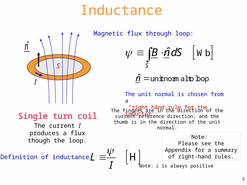
Inductance
WbˆS
B n dS n̂ unit normal to loop
The unit normal is chosen from a “right hand rule for the inductor”:
HLI
n̂
I
S
The fingers are in the direction of the current reference direction, and the thumb is in the direction
of the unit normal.
Definition of inductance:
Single turn coil
2
Note: Please see the Appendix for a summary of right-hand rules.
The current I produces a flux though the loop.
Magnetic flux through loop:
Note: L is always positive
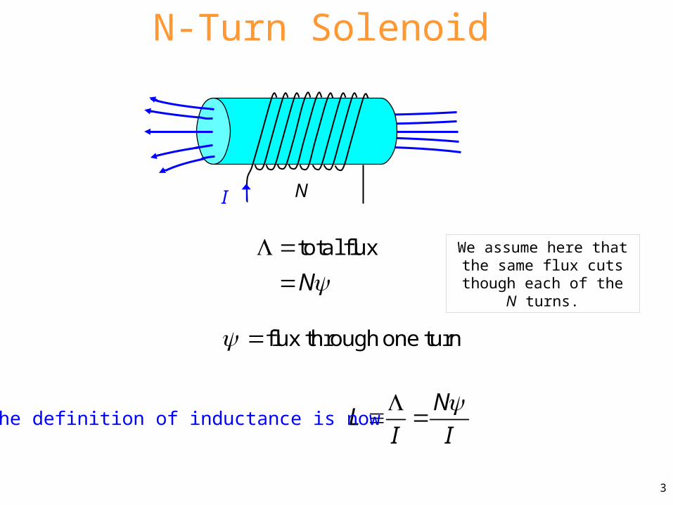
N-Turn Solenoid
N
total flux
NL
I I
flux through one turn
The definition of inductance is now
3
NI
We assume here that the same flux cuts though each of the N turns.
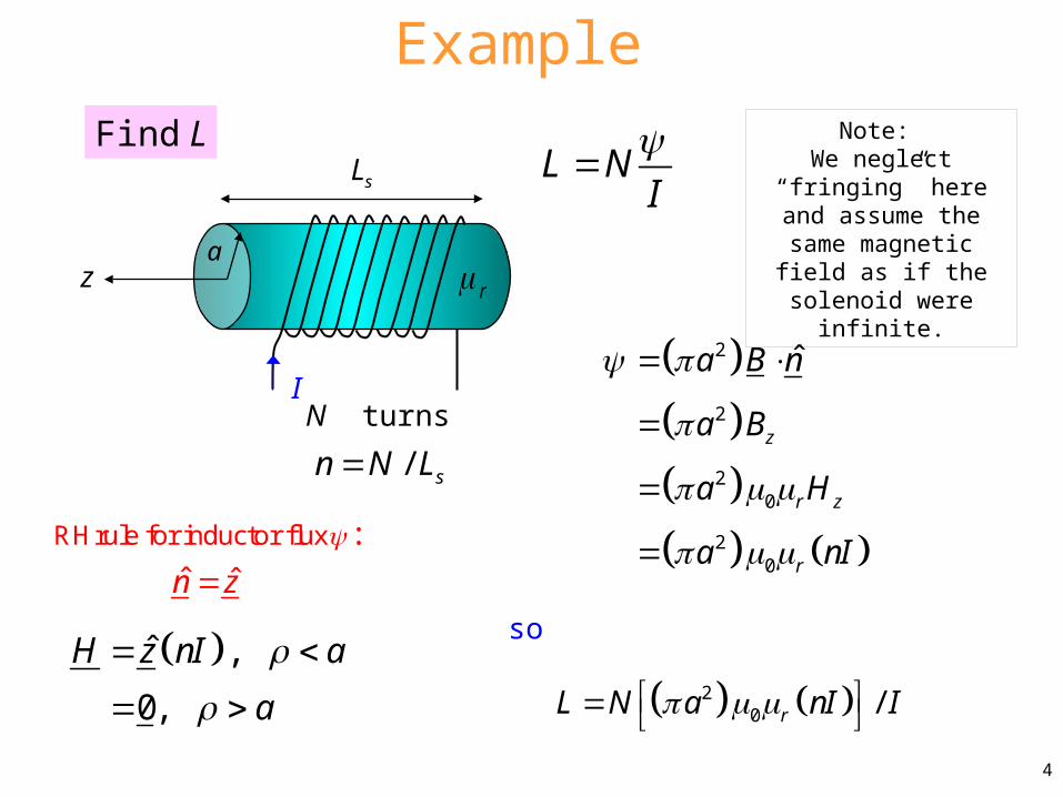
Example
2
2
20
20
ˆ
z
r z
r
a B n
a B
a H
a nI
Find LL N
I
20 /rL N a nI I
N turns
z r
I
a
Ls
so ˆ ,
0,
H z nI a
a
4
Note: We neglect “fringing” here and assume the
same magnetic field as if the solenoid were
infinite.
:
ˆ ˆn z
RHrule for inductor flux
/ sn N L

Example
2
20 Hr
s
NL a
L
N turns
z r
I
a
Ls
Final result:
5
Note: L is increased by using a high-permeability core!
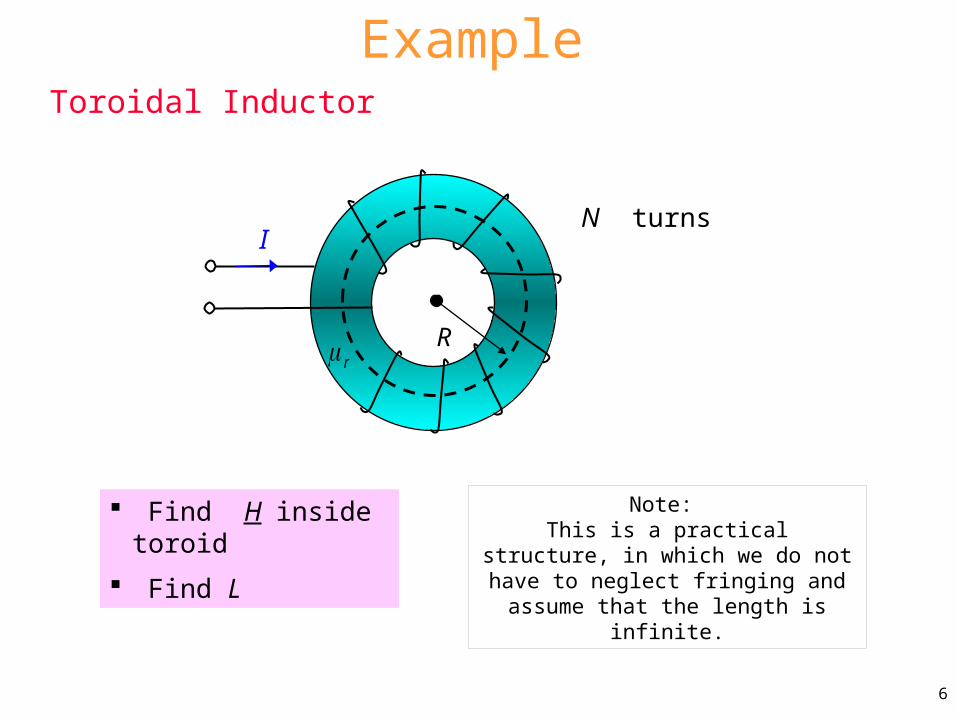
Example
Find H inside toroid
Find L
6
Note: This is a practical structure, in which we
do not have to neglect fringing and assume that the length is infinite.
Toroidal Inductor
r
IN turns
R

Example (cont.)
7

Assume
ˆH HA is the cross-sectional area:
aA
r
8
2A a
The radius R is the average radius (measured to the center of the toroid).r
IN turns
R
Example (cont.)

Example (cont.)
ˆencl
C
H d I
A/mˆ [ ]2
NIH
encl
C
H dr I
2enclI
H
Hence2
0
enclH d I
so
9
We then have
enclI NIRH rule in Ampere's law :
N turns
r
I
C r

Example (cont.)
0
0
ˆ
2
R
r R
r
NL B n A
IN
B AIN
H AIN NI
AI R
2
0 [H]2r
NL A
R
NL
I
Hence
A/mˆ [ ]2
NIH
10
ˆn̂
RH rule for inductor flux :
S
a
2A a
r
I N turns
R

Example
Coaxial cableIgnore flux inside wire and shield
Find Ll
(inductance per unit length)
A short is added at the end to form a closed loop.
S
h
+-
I
I
z
Center conductor
Note: S is the surface shaded in green.11
I
I
h
a
bz
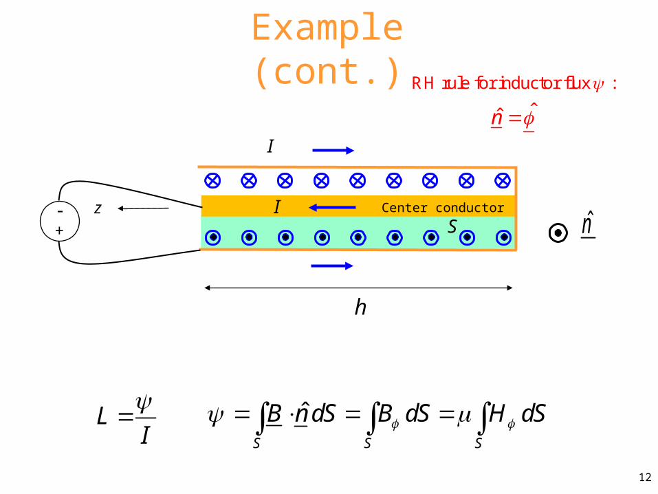
Example (cont.)
LI
ˆ
S S S
B n dS B dS H dS
n̂
12
S
h
+-
I
I z Center conductor
ˆn̂
RH rule for inductor flux :
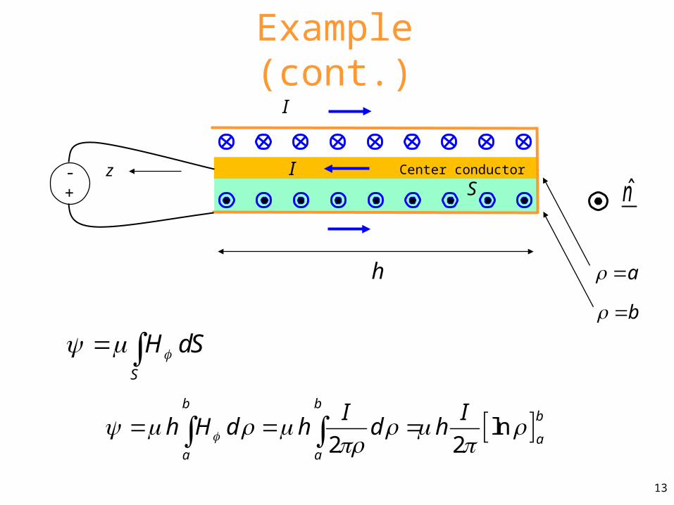
Example (cont.)
S
H dS
ln2 2
b bb
aa a
I Ih H d h d h
n̂
a
b
13
S
h
+-
I
I z Center conductor
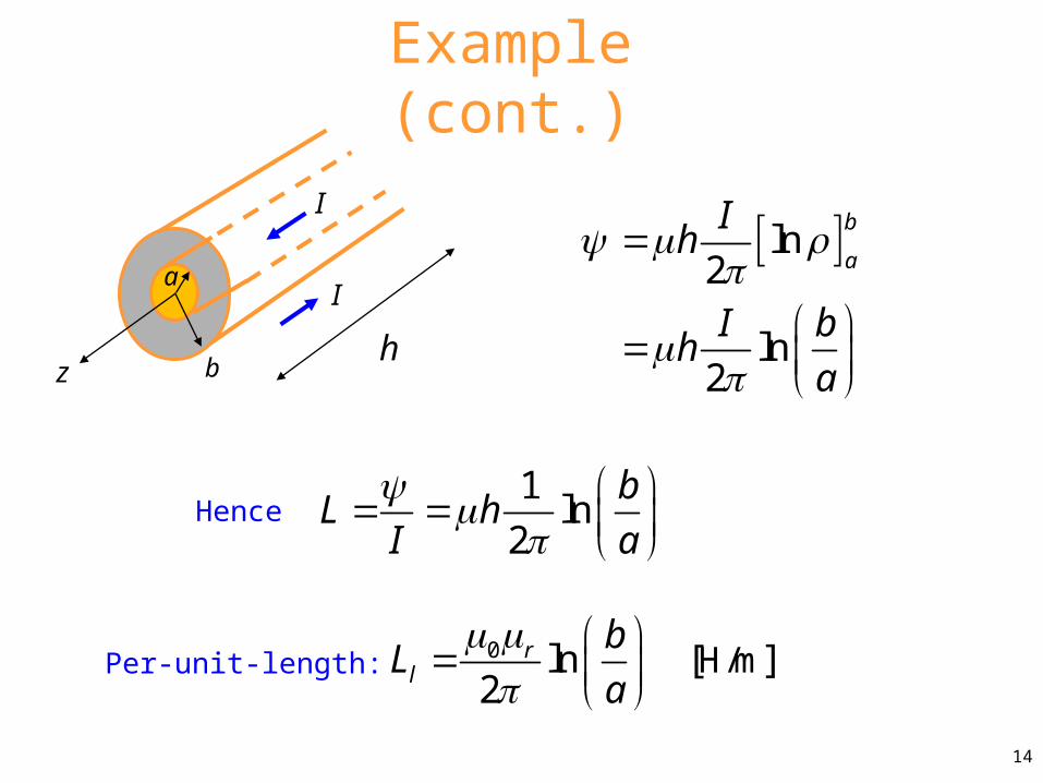
Example (cont.)
ln2
ln2
b
a
Ih
I bh
a
1ln
2
bL h
I a
0 H/mln [ ]2
rl
bL
a
Hence
Per-unit-length:
14
I
I
h
a
bz

Example (cont.)
0 H/mln [ ]2
rl
bL
a
Hence:
15
Recall:
0l
l
LZ
C
0 /m2
[F ]ln
rlC
ba
From previous notes:
00 ln [ ]
2r
r
bZ
a
00
0
376.7603 [ ]
(intrinsic impedance of free space)
Note: r =1 for most practical coaxial cables.
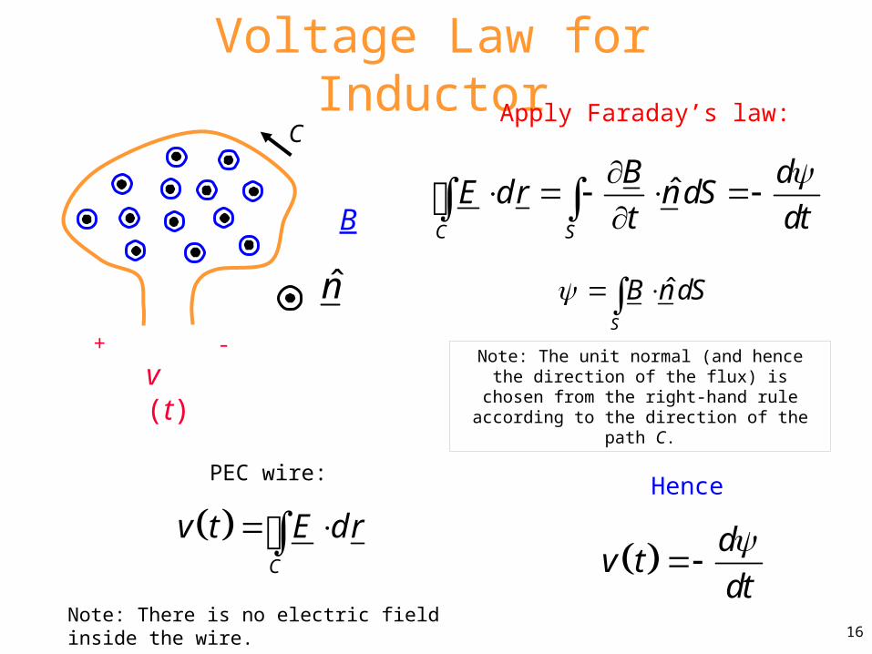
Voltage Law for Inductor
ˆC S
B dE dr n dS
t dt
C
+ -
v (t)
B
n̂
16
ˆS
B n dS
Apply Faraday’s law:
C
v t E dr Note: There is no electric field inside the wire.
PEC wire:
dv t
dt
Hence
Note: The unit normal (and hence the direction of the flux) is chosen from the right-hand rule
according to the direction of the path C.
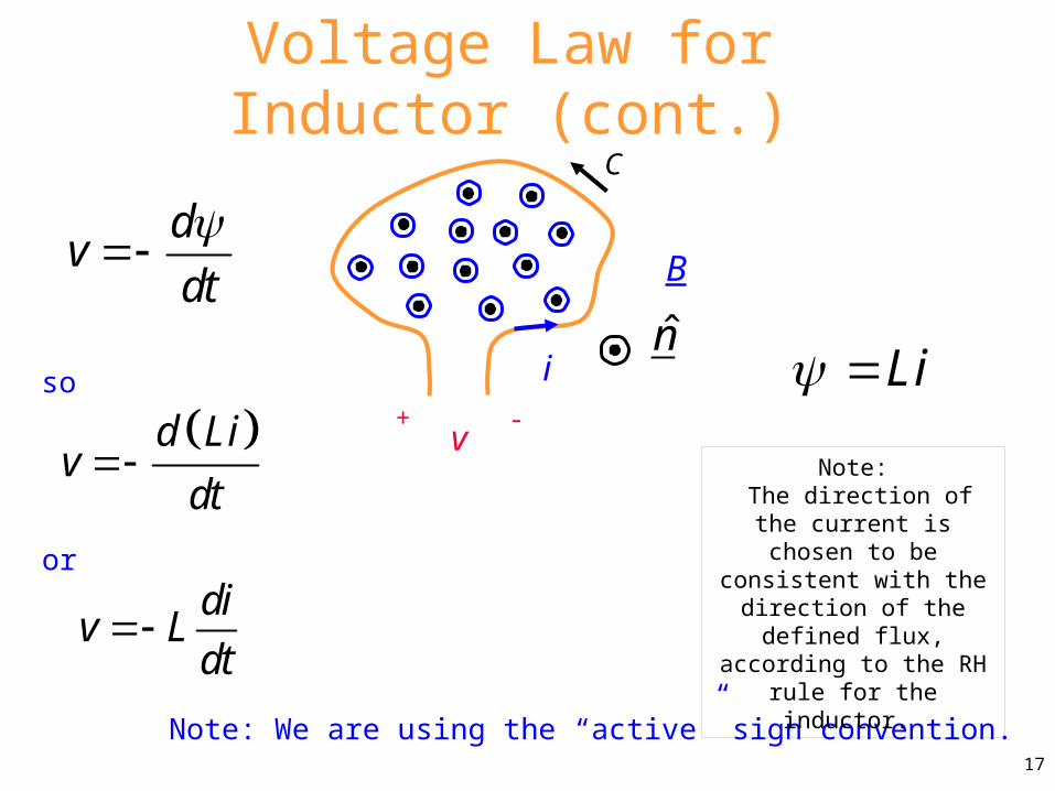
Note: We are using the “active” sign convention.
Li d Li
vdt
Voltage Law for Inductor (cont.)
dv
dt
div L
dt
i
C
+ -v
B
n̂so
or
17
Note: The direction of the
current is chosen to be consistent with the
direction of the defined flux, according to the RH
rule for the inductor.

Note: This assumes a passive sign convention.di
v Ldt
To agree with the usual circuit law (passive sign convention), we change the
reference direction of the voltage drop.
(This introduces a minus sign.)
i
+-v
B
Voltage Law for Inductor (cont.)
Passive sign convention (for loop)
18
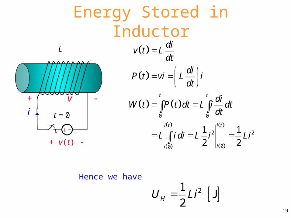
Energy Stored in Inductor
0 0
2 2
00
1 1
2 2
t t
i t i t
ii
div t L
dtdi
P t vi L idt
diW t P t dt L i dt
dt
L i di L i Li
21J
2HU Li
i t = 0
L
+ v(t) -
+ -
Hence we have
19
+ v -

Energy Formula for Inductor
2
2 HUL
I
2
1
V
L B H dVI
1
2H
V
U B H dV
We can write the inductance in terms of stored energy as:
Next, we use
We then have
20
This gives us an alternative way to calculate inductance.
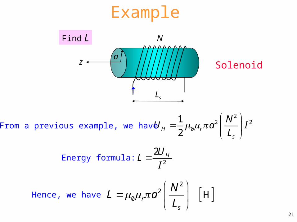
Example
22 2
0
1
2H rs
NU a I
L
Find L
2
20 Hr
s
NL a
L
Solenoid
From a previous example, we have
2
2 HUL
IEnergy formula:
Hence, we have
21
N
Ls
za
Example
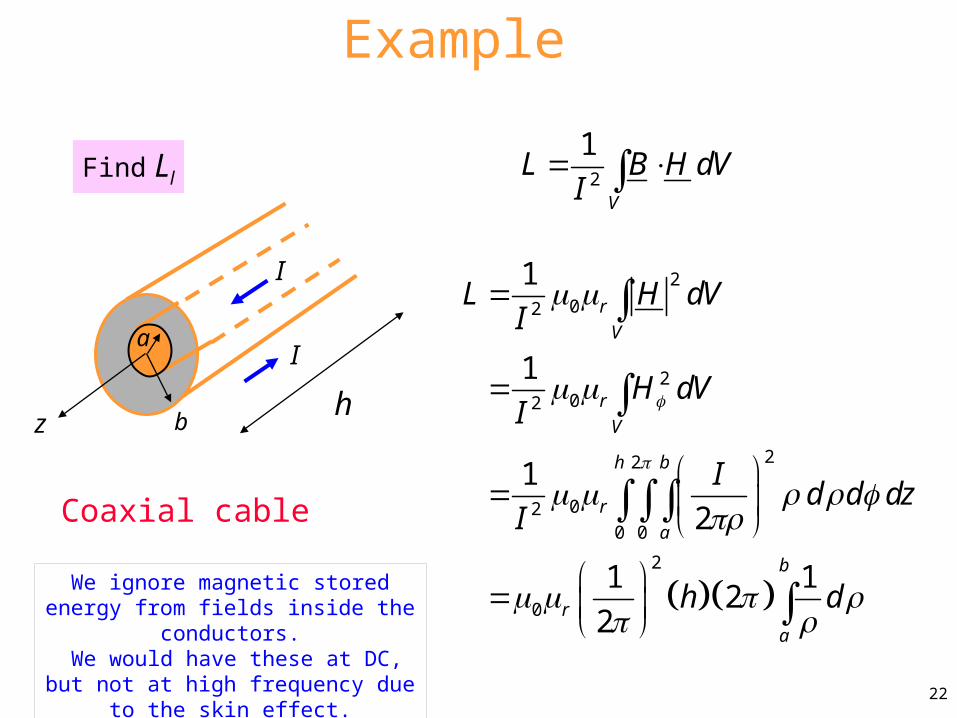
Coaxial cable
2
02
202
22
020 0
2
0
1
1
1
2
1 12
2
r
V
r
V
h b
r
a
b
r
a
L H dVI
H dVI
Id d dz
I
h d
Find Ll 2
1
V
L B H dVI
22
We ignore magnetic stored energy from fields inside the conductors.
We would have these at DC, but not at high frequency due to the skin effect.
I
I
hbz
a

Example (cont.)
2
0
0
1 12
2
ln2
b
r
a
r
L h d
h b
a
0 H/mln2
rl
bL
a
Per-unit-length:
23
Note: We could include the inner wire region if we had a solid wire at DC. We could even include the energy stored inside the shield at DC.
These contributions would be called the “internal inductance” of the coax.
I
I
hbz
a
Appendix
24
In this appendix we summarize the various right-hand rules that we have seen so far in electromagnetics.
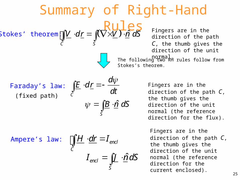
Summary of Right-Hand Rules
Faraday’s law:C
dE dr
dt
Stokes’ theorem: ˆC S
V dr V n dS Fingers are in the direction of the path C, the thumb gives the direction of the unit normal.
Fingers are in the direction of the path C, the thumb gives the direction of the unit normal (the reference direction for the flux).ˆ
S
B n dS (fixed path)
Ampere’s law: encl
C
H dr I Fingers are in the direction of the path C, the thumb gives the direction of the unit normal (the reference direction for the current enclosed).ˆencl
S
I J n dS 25
The following two RH rules follow from Stokes’s theorem.

Summary of Right-Hand Rules (cont.)
Inductor definition:
LI
Fingers are in the direction of the current I and the thumb gives the direction of the unit normal (the reference direction for the flux).
ˆS
B n dS
Magnetic field law:
For a wire or a current sheet or a solenoid, the thumb is in the direction of the current and the fingers give the direction of the magnetic field. (For a current sheet or solenoid the fingers are simply giving the overall sense of the direction.)
26