Pro/ect Electric Generating StatIon PO. Box 289 Wadsworth ... · South Texas Pro/ect Electric...
19
Nuclear Operating Company South Texas Pro/ect Electric Generating StatIon PO. Box 289 Wadsworth, Teas 77483 / December 18, 2014 NOC-AE-14003204 10 CFR 50.90 U.S. Nuclear Regulatory Commission Attention: Document Control Desk Washington, DC 20555-0001 South Texas Project Units 1 and 2 Docket Nos. STN 50-498, STN 50-499 STPNOC Response to Request for Additional Information Regarding License Amendment Request - Proposed Revision to Administrative Controls Technical Specification 6.9.1.6, "Core Operating Limits Report (COLR)" (TACs MF4639 and MF4640) References: 1. Letter from G.T. Powell, STPNOC, to NRC Document Control Desk, "License Amendment Request - Proposed Revision to Administrative Controls Technical Specification 6.9.1.6, "Core Operating Limits Report (COLR)", August 14, 2014 (ML14260A432) 2. E-mail from B.K. Singal, NRC, to L.P. Sterling, STPNOC, "Request for Additional Information (RAI) - License Amendment Request for Revision to Technical Specification 6.9.1.6 (TACs MF4639 and MF4640)", December 1, 2014 On August 14, 2014, STP Nuclear Operating Company (STPNOC) submitted a license amendment request to revise Technical Specification (TS) 6.9.1.6, "Administrative Controls Technical Specification 6.9.1.6," with respect to the revising the TS Administrative Controls section "Core Operating Limits Report (COLR)" [Reference 1]. In e-mail dated December 1, 2014 [Reference 2], the NRC requested additional information related to the STPNOC amendment request. Attachment 1 provides the STPNOC response to the Requests for Additional Information (RAI). STI: 34026099
Transcript of Pro/ect Electric Generating StatIon PO. Box 289 Wadsworth ... · South Texas Pro/ect Electric...

Nuclear Operating Company
South Texas Pro/ect Electric Generating StatIon PO. Box 289 Wadsworth, Teas 77483 /
December 18, 2014NOC-AE-1400320410 CFR 50.90
U.S. Nuclear Regulatory CommissionAttention: Document Control DeskWashington, DC 20555-0001
South Texas ProjectUnits 1 and 2
Docket Nos. STN 50-498, STN 50-499STPNOC Response to Request for Additional Information
Regarding License Amendment Request - Proposed Revision to AdministrativeControls Technical Specification 6.9.1.6, "Core Operating Limits Report (COLR)"
(TACs MF4639 and MF4640)
References: 1. Letter from G.T. Powell, STPNOC, to NRC Document Control Desk, "LicenseAmendment Request - Proposed Revision to Administrative ControlsTechnical Specification 6.9.1.6, "Core Operating Limits Report (COLR)",August 14, 2014 (ML14260A432)
2. E-mail from B.K. Singal, NRC, to L.P. Sterling, STPNOC, "Request forAdditional Information (RAI) - License Amendment Request for Revision toTechnical Specification 6.9.1.6 (TACs MF4639 and MF4640)", December 1,2014
On August 14, 2014, STP Nuclear Operating Company (STPNOC) submitted a licenseamendment request to revise Technical Specification (TS) 6.9.1.6, "Administrative ControlsTechnical Specification 6.9.1.6," with respect to the revising the TS Administrative Controlssection "Core Operating Limits Report (COLR)" [Reference 1]. In e-mail dated December 1,2014 [Reference 2], the NRC requested additional information related to the STPNOCamendment request. Attachment 1 provides the STPNOC response to the Requests forAdditional Information (RAI).
STI: 34026099

NOC-AE-14003204Page 2 of 3
There are no commitments in this letter.
If there are any questions regarding this letter, please contact Rafael Gonzales at (361) 972-4779 or me at (361) 972-7867.
I declare under penalty of perjury that the foregoing is true and correct.
11 1 LS 110 / 4Executed on
D.W. RencurrelSenior Vice President of Operations
rig
Attachments:1. Response to Requests for Additional Information, License Amendment Request,
Revision to Administrative Controls Technical Specification 6.9.1.6
2. STP Unit 2 Calibration Plan: 18" LEFM Meters and 18" ASME Nozzle Meters
3. Configuration sketches (SKDTM-24)

NOC-AE-14003204Page 3 of 3
cc:(paper copy) (electronic copy)
Regional Administrator, Region IVU. S. Nuclear Regulatory Commission1600 East Lamar BoulevardArlington, TX 76011-4511
Balwant K. SingalSenior Project ManagerU.S. Nuclear Regulatory CommissionOne White Flint North (MS 8 B1)11555 Rockville PikeRockville, MD 20852
NRC Resident InspectorU. S. Nuclear Regulatory CommissionP. 0. Box 289, Mail Code: MN1 16Wadsworth, TX 77483
Steve FrantzMorgan, Lewis & Bockius LLP
Balwant K. SingalU. S. Nuclear Regulatory Commission
John RaganChris O'HaraJim von SuskilNRG South Texas LP
Kevin PolioCris EugsterL. D. BlaylockCPS Energy
Peter NemethCrain Caton & James, P.C.
C. MeleJohn WesterCity of Austin
Richard A. RatliffRobert FreeTexas Department of State Health Services

NOC-AE-14003204Attachment 1
Attachment I
Response to Requests for Additional Information, License Amendment Request,Revision to Administrative Controls Technical Specification 6.9.1.6

NOC-AE-14003204Attachment 1
Page 1 of 1
Response to Requests for Additional Information, License Amendment Request.Revision to Administrative Controls Technical Specification 6.9.1.6.
By letter dated August 14, 2014 (Agencywide Documents Access and Management System(ADAMS) Accession No. ML14260A432, STP Nuclear Operating Company (STPNOC, thelicensee) submitted a license amendment request (LAR) for South Texas Project (STP), Units 1and 2, for revision to Technical Specification (TS) 6.9.1.6, "Core Operating Limit Report(COLR)," with respect to the analytical methods used to determine core operating limits.Specifically, the licensee plans to replace the existing Crossflow Ultrasonic Flow Measurement(UFM) System with a Cameron/Caldon Leading Edge Flow Meter (LEFM) CheckPlus Systemfor measuring feedwater flow.
The NRC staff has reviewed the information provided in this application and determined thatadditional information is required in order to complete its review. The staff's request for thefollowing additional information:
Test Fidelity and Test Range
* Please provide summary of planned tests representative of the STP configuration.* Please provide summary of planned test variations to address configuration differences.
NRC Request - RAI I
Please provide summary of planned tests representative of the STP configuration.
STPNOC Response:
Attached is the calibration plan for Unit 2 (Attachment 2). The calibration plan calibrates four (4)LEFM flow measurement spool pieces in piping configurations representative of STP Unit 2,containing Feedwater Piping Loops A, B, C and D. The plan configurations model an upstreamportion of the piping as outlined in the attached configuration sketches (Attachment 3).
The STP Unit 2 calibration plan is provided with this RAI response. Unit 2 is being calibratedfirst to support a spring 2015 installation. A similar calibration plan will be prepared to supportthe fall 2015 installation in Unit 1.
NRC Request - RAI 2
Please provide summary of planned test variations to address configuration differences.
STPNOC Response:
Attached is the calibration plan for Unit 2 (Attachment 2). The calibration that will be performedfor STP Unit 2 regarding the LEFM units is representative of the site configuration. Due tolaboratory space constraints STP Feedwater Piping Loops A and D will be calibrated in twophases.

NOC-AE-14003204Attachment 2
Attachment 2
STP Unit 2 Calibration Plan: 18" LEFM Meters and 18" ASME Nozzle Meters

NOC-AE-14003204Attachment 2
Page 1 of 7
Prepared by: Effective Date: Number:David Markowski 12/17/2014 ALD-1 161
e CAM ERON Reviewed by: Page: Revision:
Don Augenstein 1 of 7 1
STP UNIT 2 CALIBRATION PLAN: 18" LEFM METERS AND 18" ASME NOZZLE METERS
1.0 PURPOSE
This plan calibrates four (4) LEFM flow meters and (4) ASME nozzles in piping representative of theirinstallation sites at the South Texas Project (STP) Nuclear Power Plant (NPP) Unit 2. The test plan modelsan upstream portion of the installation piping (refer to SKDTM-24). The final results are calibrationcoefficients'.
2.0 SCOPE
This calibration plan applies to the four (4) 18" LEFMV/+ spool pieces manufactured by Cameron for theSTP Unit 2 NPP. In addition the following plan incorporates the pipe models that will be employed duringcollection of the nozzle calibration data (in accordance with PTC-6 recommendations). The LEFM metersand nozzles shall be installed into the calibration facility in accordance with the referenced documents.
3.0 RESPONSIBILITIES
3.1 Test Facility Responsibilities
An independent laboratory, Alden Research Laboratories (ARL), shall be responsible for providingcalibrated equipment and test facilities for this test. In addition ARL will be responsible for the Nozzlemeter calibration. The nozzles will be calibrated using a 20 point calibration in accordance with PTC-6recommendations. In order to achieve maximum flow rates and maximum Reynolds numbers, ARL willrun their flow loop at their maximum conditions allowable with respect to the model. These test conditionsare expected to be in the range as noted in Table 1.
Table 1: Calibration ParametersParameter RangeFluid Temperature 85°F to 1 10°F (varies with time)
(29°C to 43°C)Fluid Pressure Less than 65 psig
(46,000k g/m2)Flow Rate 2000 to 16,000 gpm
(450 to 3650 cubic meters/hr)
Reynolds Number 0.5 x 10⁶ to 4.2 x 10⁶
3.2 Cameron Responsibilities
The Cameron Engineering Department shall be responsible for completing the calibration plan anddocumenting the results of the test. Only the latest revision of all procedures shall be used for thiscalibration.
3.3 Prerequisites
Prior to the start of the test plan, the applicable sections of the referenced procedures shall be completed.
' Referred to as the meter factor for the LEFM and as the flow coefficient "C" for the nozzle meters.

NOC-AE-14003204Attachment 2
Page 2 of 7
Prepared by: Effective Date: Number:David Markowski 12/17/2014 ALD-1 161
r C CAM ERON Reviewed by: Page: Revision:Don Augenstein 2 of 7 1
4.0 REFERENCES
4.1 EFPOI Field Engineering Quality Control and Safety Procedure
4.2 EFP02 Control of Field Installation and Test Equipment
4.3 EFP55 LEFM Profile Factor Determination at a Flow Measurement Facility
" 25-point calibration table only
4.4 EFP68 Commissioning Procedures for LEFMV"+ C Systems
* SNRc
" Non-Fluid Delay
4.5 STP Unit 2 loops A, B, C and D Piping Isometrics References
* 7G362PFW0833, Sheet 7 Rev 0
" 7G369PFW0833, Sheet 8 Rev 6
" 7G369PFW0833, Sheet 3 Rev 6
" 7G362PFW0833, Sheet 4 Rev 1
4.6 Sketch SKDTM-24 Rev 2
4.7 Nozzle drawing 16595-01-S Rev D

NOC-AE-14003204Attachment 2
Page 3 of 7
Prepared by: Effective Date: Number:David Markowski 12/17/2014 ALD-1 161
C CAM ERON Reviewed by: Page: Revision:
Don Augenstein 3 of 7 1
5.0 CALIBRATION PROCEDURE OVERVIEW
The tests require that the LEFM'/+ spool piece section be set-up in accordance with the appropriatereferenced procedures (non-fluid tau only and SNRc). A single 8-path LEFM transmitter will be required tosupport these tests. Table 2 (following) summarizes the tests performed with a commentary as to the testpurpose.
Cameron performs tests to demonstrate hydraulic insensitivity. These parametric tests perturb the model toexplore the possibility of sensitivities. Cameron's approach is to radically perturb both the inlet conditionsand the model components.
It is noted that if the Cameron engineer determines an alteration to the test sequence is required - thenhe/she reserves the right to make modifications based upon sound engineering judgment. In addition thetest sequence may be altered in an effort to more efficiently perform the noted tests.
Table 2: Test Overview
ASME Nozzle Calibration Overview
Description Test Commentary
Straight Pipe Tests A-3, D-2 (D-3) Purpose is to collect data in order tocompute the sensitivity between straightpipe calibration (per ASME PTC 6) and themodel calibration.
Plant Model Calibration A-1 Baseline for parametric tests (includingB-i(B-3) straight pipe and changes to the inletC-l(C-2 & C-3) conditions).D-I
Model Perturbation A-2, B-2 Upstream hydraulics changed - potentiallychanging swirl.
LEFM Calibration Overview
Description Test Commentary
Model Test (correct distance A-3, B-1, D-3 Model test for parametric comparisonsbetween nozzle and LEFM)
Model Test (correct distance C-1 Loop C only: Model test for parametricbetween elbow and LEFM) comparisons
Distance to nozzle/elbow A-i, B-3, C-3, Sensitivity to distance to major upstreamchanged D- 1 feature
Upstream disturbance A-2, B-2, C-2, Sensitivity to effect of upstreamsensitivity D-2 disturbances

NOC-AE-14003204Attachment 2
Page 4 of 7
Prepared by: Effective Date: Number:David Markowski 12/17/2014 ALD- 1161
4V CAM ERON Reviewed by: Page: Revision:
Don Augenstein 4 of 7 1
Table 3 provides an estimate of the test plan schedule. The plan attempts to optimize the model sequence to
minimize setup time.
6.0 CALIBRATION PROCEDURE
Testing will be performed on the spool pieces in the piping configurations outlined below. Testing will bedone with a variety of piping configurations including a model of the system. Both pumps shall be used forall the piping configurations and all the flow rates (Note: One pump is an option for the lowest flow rates).
The laboratory shall match the model's pipe length dimensions as specified in this procedure and referencesketches within ±2 inches (+50 mm). The pipe size and schedule of the upstream pipe that the laboratoryuses shall be those specified in the attached drawings. Alternate pipe size and schedules may be used if theyagree with the pipe inside diameter (for example 16 inch standard schedule has comparable inside diametersto 18 inch heavy schedule).
Note 1: For all tests, confirm flow rates at maximum flow that the lab can provide without cavitation. Thelaboratory may have inadequate line pressure such that the fluid might cavitate at the higher flows.Therefore - some testing is required to determine the maximum test flow rate.
Note 2: The flows to be tested will extend from the maximum flow ARL can provide using the standardCameron 25-point calibration method from the meter's 10:1 turndown up to the maximum available. Forparametric tests - the lowest flow rates are optional or may be substituted for intermediate flow rates.
Note 3: Reference the attached sketch of the models.
6.1 Loop A Test
6.1.1 A-i Parametric test for LEFM (model configuration upstream of nozzle but LEFM is closer than inplant at 18' 10-1/2" downstream of nozzle)
A-I Model test for ASME nozzle
Parametric test with LEFM spool piece transducers installed in the horizontal plane per page2 of SKDTM-24 with a pipe extension installed off the end of the header. Distance betweenthe nozzle discharge (item A3) and the LEFM inlet (item A4) set at 18' 10-1/2". Perform anASME PTC-6 twenty (20) point calibration. (Test A-I reference SKDTM-24)
6.1.2 A-2 Parametric for LEFM (upstream hydraulics perturbation test)
A-2 Model test for ASME nozzle (upstream hydraulics perturbation test)
Install a 25% restriction/blockage on the bottom of the 36" header. Remainder of the pipingremains the same.
6.1.3 A-3 Model test for LEFM (correct length between LEFM and nozzle)
A-3 Straight pipe test for ASME nozzle
36 Inch header is removed and nozzle installed in a straight pipe configuration. 29' 1-1/8" ofpipe is between the nozzle outlet (item A3) and the LEFM inlet (item A4) - please referencetest A-3 on SKDTM-24.
NOC-AE-14003204Attachment 2
Page 5 of 7
Prepared by: Effective Date: Number:David Markowski 12/17/2014 ALD-1 161
er CAMERON Reviewed by: Page: Revision:
Don Augenstein 5 of 7 1
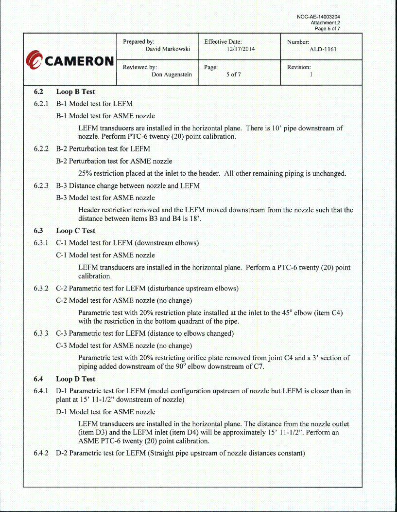
6.2 Loop B Test
6.2.1 B-I Model test for LEFM
B-1 Model test for ASME nozzle
LEFM transducers are installed in the horizontal plane. There is 10' pipe downstream ofnozzle. Perform PTC-6 twenty (20) point calibration.
6.2.2 B-2 Perturbation test for LEFM
B-2 Perturbation test for ASME nozzle
25% restriction placed at the inlet to the header. All other remaining piping is unchanged.
6.2.3 B-3 Distance change between nozzle and LEFM
B-3 Model test for ASME nozzle
Header restriction removed and the LEFM moved downstream from the nozzle such that thedistance between items B3 and B4 is 18'.
6.3 Loop C Test
6.3.1 C-I Model test for LEFM (downstream elbows)
C-I Model test for ASME nozzle
LEFM transducers are installed in the horizontal plane. Perform a PTC-6 twenty (20) pointcalibration.
6.3.2 C-2 Parametric test for LEFM (disturbance upstream elbows)
C-2 Model test for ASME nozzle (no change)
Parametric test with 20% restriction plate installed at the inlet to the 450 elbow (item C4)with the restriction in the bottom quadrant of the pipe.
6.3.3 C-3 Parametric test for LEFM (distance to elbows changed)
C-3 Model test for ASME nozzle (no change)
Parametric test with 20% restricting orifice plate removed from joint C4 and a 3' section ofpiping added downstream of the 900 elbow downstream of C7.
6.4 Loop D Test
6.4.1 D-1 Parametric test for LEFM (model configuration upstream of nozzle but LEFM is closer than inplant at 15' 11-1/2" downstream of nozzle)
D-1 Model test for ASME nozzle
LEFM transducers are installed in the horizontal plane. The distance from the nozzle outlet(item D3) and the LEFM inlet (item D4) will be approximately 15' 1 1-1/2". Perform anASME PTC-6 twenty (20) point calibration.
6.4.2 D-2 Parametric test for LEFM (Straight pipe upstream of nozzle distances constant)

NOC-AE-14003204Attachment 2
Page 6 of 7
Prepared by: Effective Date: Number:David Markowski 12/17/2014 ALD-1 161
e CAM ERON Reviewed by: Page: Revision:
Don Augenstein 6 of 7 1
D-2 Parametric test for ASME nozzle (Straight pipe)Header removed and distance between nozzle outlet (item D3) and LEFM inlet (item D4)unchanged from test D-1.
6.4.3 D-3 Model test for LEFM (correct distance from nozzle)
D-3 Parametric test for ASME nozzle (Straight pipe)
Distance between nozzle outlet (item D3) and LEFM inlet (item D4) at 36' 1-1/8".
Table 3: Schedule Estimates
Schedule PlanSchedule_ (Reference SKDTM-24)
Unpack and setup Loop ACommission Loop A
Sunday Setup Loop BCommission Loop B (if possible)
Monday Test A- ITest A-2
Test A-3Tuesday Test B- 1
Test B-2
Test B-3Wednesday Setup and Commission Loop C
Test C-I
Test C-2Thursday Test C-3
Setup and Commission Loop D
Test D- 1Friday Test D-2
Test D-3
Saturday Contingency/Clean Up
Sunday Contingency/Clean Up
NOC-AE-14003204Attachment 2
Page 7 of 7
Prepared by: Effective Date: Number:David Markowski 12/17/2014 ALD-1 161
C CAM ERON Reviewed by: Page: Revision:
Don Augenstein 7 of 7 1
7.0 TEST DOCUMENTATION
7.1 The commissioning procedure shall be completed for the meter(s).
7.2 The Cameron Test Engineer shall collect all "raw" field data into one volume (directory) and indexthe data for each test. This data shall contain the LEFM setup data, data logs, and facility data thatincludes weigh tank measurements of flowrate and water temperature. Each piping component shallbe listed for each test configuration (EFP55).
7.3 The Cameron Test Engineer shall collect all "on-site" data analysis sheets into one volume(directory) and index for each test.
7.4 The Cameron Test Engineer shall collect ARL temperature data and the LEFM calculatedtemperature, and calculated sound velocity.
7.5 The Cameron Test Engineer shall collect normalized velocity distribution (i.e., path by pathvelocities) and evaluate the values for the Cameron report.
7.6 The Cameron Test Engineer shall summarize the data in a report. The report shall indicate theLEFM meter factor and uncertainty for the selected location.
7.7 The Independent Laboratory, in this case ARL, shall provide a reports for the test sequence and datacollected, nozzle calibration data, and a calibration record for all calibrated equipment

NOC-AE-14003204Attachment 3
Attachment 3
Configuration sketches (SKDTM-24)

NOC-AE-14003204Attachment 3
Page 1of5
-FLOW
TOFW-2015
TOFW-2013
TOFW-2011
TOFW-2017
36" HEADERO.D = 36"ID. = 31.25"

36" HEADER
NOC-AE-14003204Attachment 3
Page 2 of 5
LOOP A 51018.00" O.D,15.25" ID.
DO NOT SCALE VL•ESAM O EU&-'A7- 131 ýý 14MEAEON ASUREMENT
TAC 31 Oct 14S•- -SOUTH TEXAS PROJECT
31 Oct 14 UNIT 2, ALDEN
31 Oct 14 SKETCH2 t8 I SKDTM-24 02
TO SUMP

NOC-AE-14003204Attachment 3
Page 3 of 53" HEADER
LOOP B 52018.00" O.D.15.25" I.D.TO SUMP

NOC-AE-14003204Attachment 3
Page 4 of 5
I0

NOC-AE-14003204Attachment 3
Page 5 of 53V HADRB
LOOP D 54018.00" O.D.15.25" ID.
DO NOT SCALE DgAMERON vES14-,CAMERON -MEASUREMENT
TC 31 Oct 14T,• 131 Oct 14 SOUTH TEXAS PROJECT
31 Oct 14 UNIT 2, ALDEN
31 Oct 14 SKETCH....I 57s 5' 1 SKDTM-24 0•2
TO SUMP