Produkt bild - kaller.com · passive gas spring, the pressure in its upper gas chamber is reduced...
54
Would you like to order this product? All available information at kaller.com. Bild Produkt bild Product Series Delayed Return Units Controllable Gas Springs – KF2 Edition 13. 2016 © KALLER
Transcript of Produkt bild - kaller.com · passive gas spring, the pressure in its upper gas chamber is reduced...

Would you like to order this product? All available information at kaller.com.
Bild
Produktbild
Product Series Delayed Return Units
Would you like to order this product? All available information at kaller.com.
Controllable Gas Springs – KF2Edition 13. 2016 © KALLER

CONTENTS
kaller.comWe reserve the right to add, delete or modify components without notification. © KALLER Edition 13. 2016
GENERAL INTRODUCTION ............................................................................................... 1.1About Controllable Gas Springs ................................................................................... 1.1
Standard Lock, KF2 .................................................................................................... 1.2
Positive lock system, KF2 + KP .................................................................................. 1.3
APPLICATION EXAMPLES ................................................................................................. 2.1Standard Lock, KF2 ..................................................................................................... 2.1
Positive Lock System, KF2 + KP ................................................................................. 2.2
APPLICATION ENQUIRY FORM ......................................................................................... 3.1
SYSTEM CONFIGURATION ................................................................................................ 4.1Control system (mandatory)......................................................................................... 4.1
Hose system (optional) ............................................................................................... 4.3
Cooling system (optional) ............................................................................................ 4.5
Overheat protection .................................................................................................... 4.7
TECHNICAL DATA ............................................................................................................... 5.1KF2 – Dimensions, standard version ........................................................................... 5.1
KF2-A – Dimensions, adjustable version .................................................................... 5.2
Gas springs with cooling .............................................................................................. 5.3
KP – Dimensions ......................................................................................................... 5.4
Valve block dimensions ................................................................................................ 5.5
Control system components ........................................................................................ 5.6
Liquid cooling system components .............................................................................. 5.8
Nitrogen cooling system ............................................................................................. 5.12
Information sign ......................................................................................................... 5.16

CONTENTS
We reserve the right to add, delete or modify components without notification. © KALLER Edition 13. 2016kaller.com
This product is protected by Patent No. US 5,588,641, US 5,435,530, EP 0 581 832, EP 0 830 524.
INSTALLATION EXAMPLES ................................................................................................ 6.1Control System – Standard lock, KF2 .......................................................................... 6.1
Control System – Positive lock system, KF2 + KP ....................................................... 6.2
Hose System – Standard lock, KF2 ............................................................................. 6.3
Hose System – Positive lock system, KF2 + KP .......................................................... 6.5
KF2 connection – NC Standard lock with a Nitro CoolerTM .......................................... 6.7
KF2-NC connection – Positive lock with a Nitro CooleTM .............................................. 6.8
Four KF2-NC connection – Standard lock with a Nitro CoolerTM .................................. 6.9
FREQUENTLY ASKED QUESTIONS (FAQ’S) ..................................................................... 7.1
TROUBLESHOOTING .......................................................................................................... 7.6
APPENDIX ............................................................................................................................ 8.1Stroke length adjustment of KF2-A .............................................................................. 8.1
How does the new KF2 differ from an existing KF? ..................................................... 8.3
How to fit the new KF2 to existing KF systems ............................................................ 8.3
KF2/KF2-A Mounting information ................................................................................. 8.4
kaller.comWe reserve the right to add, delete or modify components without notification. © KALLER Edition 13. 2016
Baby blank-holder
KF2 Spring
KF2
0Time
max press stroke
Stroke
max spring stroke
Pres
sSpr
ing
13
0
Max 1 mm springback
Time
max press stroke
Stroke
max spring stroke
Pres
sSpr
ing
KF2
0Time
max press stroke
Stroke
max spring stroke
Pres
sSpr
ing
13
0
Max 1 mm springback
Time
max press stroke
Stroke
max spring stroke
Pres
sSpr
ing
1.1
GENERAL INTRODUCTION
Standard lock KF2
About Controllable Gas Springs
KF2 is the next generation of controllable gas springs, which supersedes the KF springs.
The KF2 controllable gas spring series consists of a family of gas springs for use in metal form-ing dies, whose piston rods can be locked at bottom dead center (BDC). The return stroke of the piston rod is controlled via the valve con-tained within the base of the spring.
One application example is in drawing dies (see below) where two forming stages are performed with a single press stroke.
More examples illustrating the benefits of using controllable gas springs can be found in section Applications Examples 2/1.
Controllable gas springs are available with:
• Model sizes 1500, 3000, 5000 & 7500(initial force in daN)
• Stroke lengths from 5 mm to 160 mm
There are two controllable gas springsystems available:
• Standard lock, KF2
• Positive lock system, KF2 + KP
The following is a brief description of these two systems.
We reserve the right to add, delete or modify components without notification. © KALLER Edition 13. 2016kaller.com 1.2
KF2
0Time
max press stroke
Stroke
max spring stroke
Pres
sSpr
ing
13
0
Max 1 mm springback
Time
max press stroke
Stroke
max spring stroke
Pres
sSpr
ing
[3]
[2][1]
[4]
[5]
Upper gas chamber
Lower gas chamber
KF2
0Time
max press stroke
Stroke
max spring stroke
Pres
sSpr
ing
13
0
Max 1 mm springback
Time
max press stroke
Stroke
max spring stroke
Pres
sSpr
ing
Typical standard lock curve
[4]
GENERAL INTRODUCTION
Standard Lock, KF2
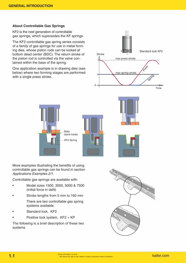
The KF2 is a controllable gas spring whose piston rod can be locked at BDC.
The full stroke length of the KF2 spring must be used within ±0.5 mm for optimal locking function to provide maximum springback of 1 mm, which we refer to as standard lock (for zero springback see Positive lock System).
The return stroke of the piston is either controlled by the control system from the press or can be in-tegrated into the tool itself (for more info, see Tool integrated control system, page 4.2). The springs can either be installed self-contained or connected to a control block through a hose system.
KF2 – how does it work?
The KF2 controllable gas spring consists of a cylinder [1], guide assembly [2], piston rod assembly containing check valves [3], internal piston rod [4] and normally open (NO) cartridge valve [5] located in the base of the spring.
The nitrogen gas within the spring is sealed within an upper and a lower gas chamber. When the spring is stroked, nitrogen gas from the lower chamber passes through the check valves in the piston rod assembly and enters the upper cham-ber.
The cartridge valve is closed by applying com-pressed air pressure (min. 4 bar). With the car-tridge valve closed, the piston rod is prevented from returning to its extended position.
By opening the cartridge valve again, the gas con-tained within the upper chamber can now return to the lower chamber via the internal piston rod [4], thus allowing the piston rod to return to its extended position.

kaller.comWe reserve the right to add, delete or modify components without notification. © KALLER Edition 13. 20161.3
13
0Time
Max 0 mm springback
Max press stroke
Max spring stroke
Spring
Press
Stroke
KF2 spring Valve block KP spring[1] [3][2]
KP Upper Chamber
KF2 Lower Chamber
GENERAL INTRODUCTION
Positive Lock System, KF2 + KP
The KF2 + KP system combines a standard lock, i.e. a KF2 controllable gas spring [1], with a specially designed KP passive gas spring [3] via a valve lock [2], which together forms a posi-tive lock system.
The result is a controllable gas spring system with zero springback.
Please note! The KP passive gas spring is not to be used for any operation in the tool other than to elimi-nate springback in the KF2 spring(s). It can be placed anywhere in the tool and can eliminate springback in up to four KF2 controllable gas springs. How much the KP passive gas spring should be stroked depends on the number of KF2 springs in the system. The cartridge valve in the valve block is identical to the one in the KF2 spring.
Positive Lock System, how does it work?
The KF2 is the active spring in the system and provides the required spring force in the tool. The task of the KP passive gas spring is to eliminate the max. 1 mm springback of the KF2 spring(s) at press BDC.
The system works by connecting the lower gas chamber in the KF2 controllable gas spring(s) to the upper chamber of the KP passive gas spring via the valve block. By stroking the KP passive gas spring, the pressure in its upper gas chamber is reduced causing a pressure differ-ence between it and the lower gas chamber in the KF2 controllable gas spring(s).
At BDC, the valve in the valve block is opened, using the control system from the press or a mechanical pressure switch, and the remaining gas in the lower chamber of the KF2 spring is drawn into the upper chamber of the KP passive gas spring.

We reserve the right to add, delete or modify components without notification. © KALLER Edition 13. 2016kaller.com 1.4
0
Max 1 mm springback
Time
max press stroke
Stroke
max spring stroke
Pres
sSpr
ing
Max 0 mm springback
[3]Standard lock KF2 Positive lock KF+KP
GENERAL INTRODUCTION
Why 100% nominal stroke ±0.5 mm?
In order to provide optimum locking from the KF2 controllable gas spring, it is important to stroke the spring 100% of the nominal stroke length ±0.5 mm.
This is because it is necessary to reduce the gas volume in the lower gas chamber to a minimum.
For a standard lock, stroking the KF2 spring 100% of the nominal stroke length ±0.5 mm will ensure maximum springback of 1 mm.
An adjustable stroke length version of the control-lable gas spring, called the KF2-A, is available for those applications where the exact nominal stroke length ±0.5 mm is not known until after tool try-outs.
For a positive lock system with KF2 + KP, stroking the KF2 spring 100% of the nominal stroke length ±0.5 mm is also important, although this also largely depends on the utilized stroke length of the KP passive gas spring.

kaller.comWe reserve the right to add, delete or modify components without notification. © KALLER Edition 13. 20162.1
APPLICATION EXAMPLES
Standard Lock, KF2
When forming this cross member, “baby” blank holders are used to form the circled area. TThe tool uses two “baby” blank holders, which during the return stroke must be locked in the bottom position to avoid deformation of the part. In this case, one KF2 spring is used to control each “baby” blank holder.
As the press opens, the baby blank holder remains locked until that time when the KF2 spring should be unlocked and eject the part.
At bottom dead center, the KF2 springs will lock. In this application, a small amount of springback will not damage the formed part.
Work cycle
[1]
KF2 Spring
Baby blank holder
As the upper tool moves downwards, the blank holder [1] is activated to control the flow of the blank in the tool.
Part:Vehicle floor cross member
Standard Lock, KF2

We reserve the right to add, delete or modify components without notification. © KALLER Edition 13. 2016kaller.com
Positive Lock System, KF2 + KP
For parts where controllable gas springs with zero springback are required, the positive lock system is ideal.
Here a double-stage draw forming operation is made with a single stroke from the press.
The positive lock system provides a lockable blank holding force that prevents part deformation during the return stroke of the press.
This large die for an inner door panel uses a total of 12 pcs KF2 connected to 3 pcs KP passive gas springs.
Work cycle
As the tool opens, the KF2 springs remain locked until a signal from the press is given. The KF2 springs then help eject the undamaged part from the tool.
As the tool comes together, the KP passive gas springs (not shown) are stroked, providing the necessary back pressure to lock the KF2 springs at BDC with zero springback.
The lower tool contains the KF2 controllable gas springs that provide the active blank-holding force for the deepest drawn section of the part.
2.2
Positive Lock System, KF2 + KP
Part:Vehicle inner door panel
APPLICATION EXAMPLES
kaller.comWe reserve the right to add, delete or modify components without notification. © KALLER Edition 13. 2016
Evac.Ez hose
Fill.
Evac.Ez hose
Fill.
Evac.Ez hose
Fill.
Evac.Ez hose
Fill.
2.3
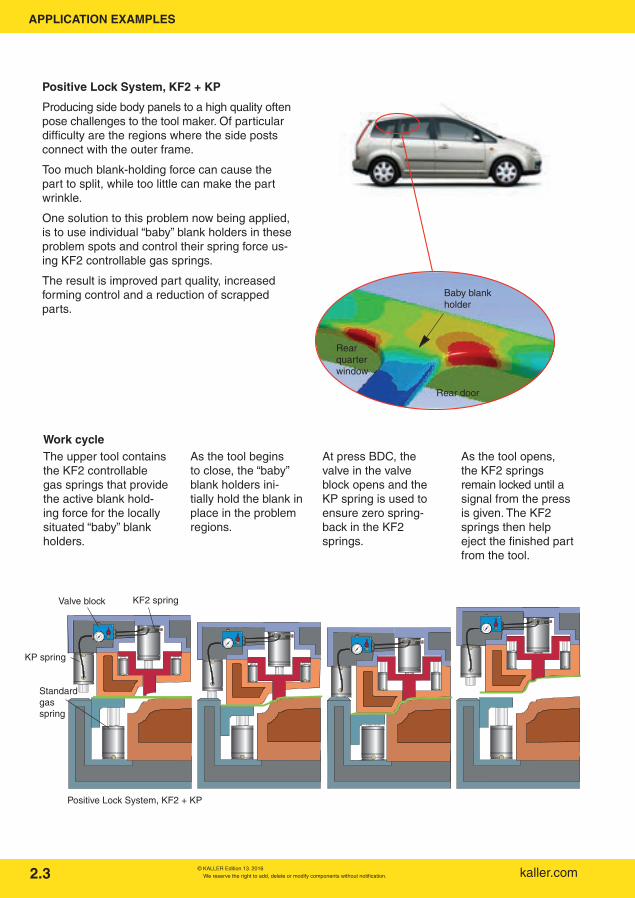
Work cycle The upper tool contains the KF2 controllable gas springs that provide the active blank hold-ing force for the locally situated “baby” blank holders.
As the tool begins to close, the “baby” blank holders ini-tially hold the blank in place in the problem regions.
At press BDC, the valve in the valve block opens and the KP spring is used to ensure zero spring-back in the KF2 springs.
As the tool opens, the KF2 springs remain locked until a signal from the press is given. The KF2 springs then help eject the finished part from the tool.
KP spring
Valve block KF2 spring
Positive Lock System, KF2 + KP
Standard gas spring
Rear quarter window
Baby blank holder
Rear door
APPLICATION EXAMPLES
Positive Lock System, KF2 + KP
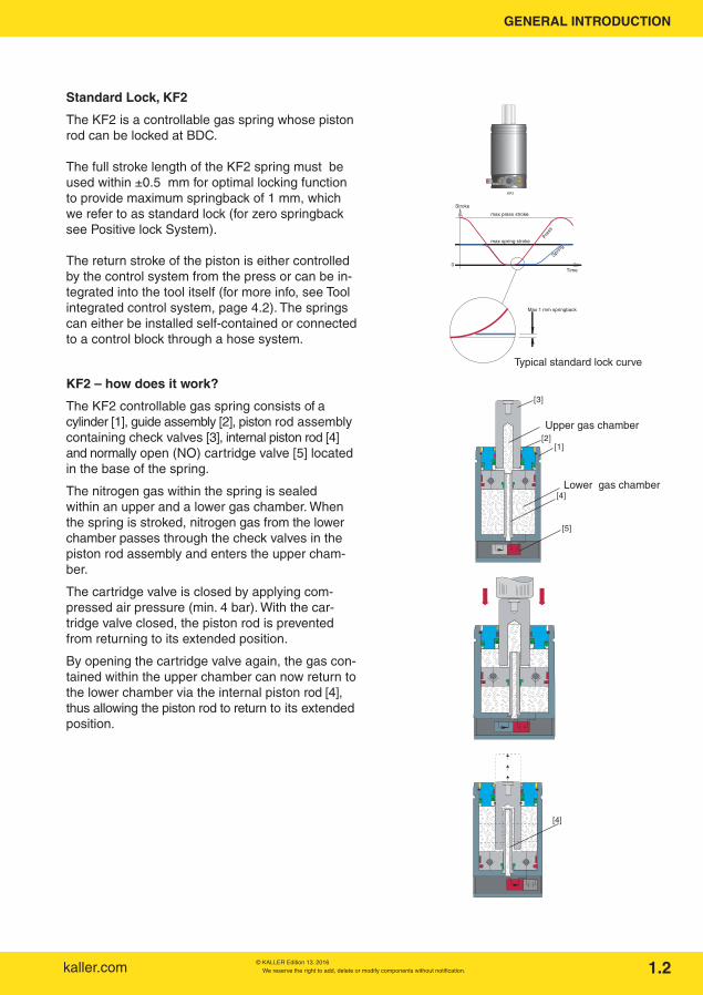
Producing side body panels to a high quality often pose challenges to the tool maker. Of particular difficulty are the regions where the side posts connect with the outer frame.
Too much blank-holding force can cause the part to split, while too little can make the part wrinkle.
One solution to this problem now being applied, is to use individual “baby” blank holders in these problem spots and control their spring force us-ing KF2 controllable gas springs.
The result is improved part quality, increased forming control and a reduction of scrapped parts.

We reserve the right to add, delete or modify components without notification. © KALLER Edition 13. 2016kaller.com 3.1
APPLICATION ENQUIRY FORM
To make selection of the right system and components for your particular application easier, please fill in the Application Enquiry Form below.
We recommend you make a photocopy of this page, complete the following questions and send it to your local KALLER distributor or to contact us directly at Strömsholmen for further assistance.
If possible, please provide the following information together with a rough sketch of your application.
General information
Date:…………................................................................................................................(yy/mm/dd)
Your name:…..…………………………..……….................................................................................
How do you wish to be contacted?
• Via phone:………………..….............................................................................(give details)
• Via fax:……………….......................................................................….............(give details)
• Via e-mail:…...…..............................................................................................(give details)
Country you are contacting us from: …………………………………..……………………..................
Application information
1. Does your application require a gas spring with lockable piston rod (Y/N)?…….................
2. If you answered Yes to Question 1, is a max. 1 mm springback acceptable (Y/N)? ..................
3. How many gas springs does your application require?……………………….……............pcs
4. What initial force is required from each gas spring?……..………..………......……...........daN
5. What stroke length is required for each gas spring?…………..….................….................mm
6. How many strokes per minute (spm) will your application run at?….……........................spm
7. The springs should be connected together using a Hose System ......................................
Additional comments: …………………………………………………………………………………………………………………………………………………………………………………………………………………………………………………………………………………………………………………………………………………………………………………………………........................................................................................…...........................................................................................................................................................................……………………………………………………........................................................................................….......................................................................

kaller.comWe reserve the right to add, delete or modify components without notification. © KALLER Edition 13. 20164.1
SYSTEM CONFIGURATION
0
Stroke(mm)
t0 t1 t2
Max press stroke
Max spring stroke
Spring locked
Time
Control signal
t0 t1 t2
Open Closed Open
0
Max press stroke
Max spring stroke
Pres
s
Spring
Open Closed Open
- t0 = Die closed - t1 = Press Bottom Dead Center- t2 = Start of spring return stroke
KF2 spring valve
13
Min 4 bar0 bar
Controllable gas springs require at least one of the following systems:
• Control system (mandatory)
• Hose system (optional)
• Cooling system (optional)
Control system (mandatory)
In order to lock and unlock the KF2 controllable gas spring(s), a control system is required to send a pneumatic signal (min. 4 bar) to the normally open (NO) valve in the base of the KF2 spring.
The pneumatic signal can either be provided by the control system from the press, or integrated into the tool itself using mechanical pressure switches (see Tool integrated control system 4.2 for more information).
Control system – Standard Lock, KF2
The normally open (NO) valve within the base of the KF2 controllable spring(s) is closed us-ing compressed air (min. 4 bar). With the valve closed at t0-t2 (see diagram), the piston rod of the KF2 spring(s) is prevented from returning to its extended position.
By connecting the valves in the KF2 springs to each other using pneumatic hoses to the control system of the press, the springs can be easily locked and subsequently unlocked.
If only an electrical control signal is available from the press, then a standard electric- pneumatic control valve can be used.
For examples of how to connect the KF2 control-lable gas spring(s) to a control system, see the installation examples on page 6.1.

We reserve the right to add, delete or modify components without notification. © KALLER Edition 13. 2016kaller.com 4.2
Open
Open
Open
Closed
Closed
Closed
Closed
Closed
t0 t1 t2
Min 4 bar0 bar
Air signal A Signal to Port 4
Min 4 bar0 bar
0
Stroke(mm)
Max press stroke
Max spring stroke
Spring locked
Time0
Max press stroke
Max spring stroke
Pres
s
Spring
- t0 = Approximately when closing the die- t1 = Press Bottom Dead Center- t2 = Start of spring return stroke
KF2 spring valve
Valve Block valve
t0 t1 t2
50
13
Air signal C to Port C on the valve block
[2]
[1]
SYSTEM CONFIGURATION
Control system – Positive Lock System, KF2+KP
When the KP passive gas spring is connected to the active KF2 spring(s) via the valve block, an additional signal from the press (or separate mechanical pressure switch) is required to control the valve within the valve block.
As the valve in the valve block is identical to that used in the KF2 springs, it is normally open (NO). Therefore during the down-stroke of the press, it is important the valve block’s valve is closed by applying compressed air (min. 4 bar) to air port C.
Please note! The valve in the valve block should be opened exactly at press BDC.
For examples of how to connect the KF2 + KP controllable gas spring system to a control system, see the installation examples on page 6.1.
Tool integrated control system
The control system, required to lock the KF2 spring(s), can be integrated into the tool itself by using a mechanical pressure switch. The control system required to lock and unlock the KF2 spring(s) is then becomes independent of the press’ own control system.
The KF2 spring(s) remain locked as long as the mechanical pressure switch [1] is activated by the tool [2].
When a positive lock system is used, the mechanical switch is recommended to control only the KF2 gas springs (signal A). To obtain the proper signal (C) to valve block an electric pneumatic 3/2 valve is recommended.
As a result, a tool integrated control system only requires a constant supply of compressed air (min. 4 bar) to the mechanical pressure switch.

kaller.comWe reserve the right to add, delete or modify components without notification. © KALLER Edition 13. 2016
4.3
1 3
Standard control block
KF2
Controllable gas spring system
Recommended hose system
Standard lock EZ hose
Positive lock system EZ hose and EO24 hose
SYSTEM CONFIGURATION
Hose system (optional)
KF2 controllable gas springs can be installed in the tool as self-contained units or linked together using a hose system for remote gas charging and evacuation.
Hose system – Standard Lock, KF2
With reference to Chapter 4 of the KALLER main catalog, we recommend use of the EZ hose System.
KF2 controllable gas springs are connected to each other in a hose system in just the same way as standard gas springs. For information on connecting the newer KF2 springs with the older KF controllable gas springs, see Appendix “How to fit the new KF2 to existing KF Systems” on page 8.2.
For examples of how to connect KF2 controllable gas springs to a hose system, see the installation examples on page 6.1.

We reserve the right to add, delete or modify components without notification. © KALLER Edition 13. 2016kaller.com 4.4
1 3EZ-hose
EO24-hose
SYSTEM CONFIGURATION
Hose system – Positive Lock System, KF2+KP
It is possible to connect up to four KF2 springs to one valve block.
With reference to Chapter 4 of the KALLER main catalog, a KF2+KP controllable gas spring system requires two hose connections:
• One EZ hose connection
• One EO24 hose connection
EZ hose connections
Gas port 1, which is marked on each KF2 spring, is connected to gas port 1 on the valve block (also marked) using EZ hose system components.
EO24 hose connections
To connect the KF2 controllable gas spring(s) to a KP passive gas spring via the valve block, we recommend using the EO24 hose system (or its equivalent) owing to the large internal diameter of the hose. This is especially important when gas flow in the hoses is required.
Gas port 3, which is marked on each KF2 spring, is connected to gas port 3 on the valve block (also marked) using EO24 hose system components
Gas port 5, which is marked on the valve block, is connected to gas port 5 (also marked) on the KP passive gas spring also using EO24 hose system components.
For information on connecting the newer KF2 springs together with the older KF controllable gas springs, see appendix “How to fit the new KF2 to existing KF systems” on page 8.2.
For examples of how to connect KF2 + KP control-lable gas spring systems to a hose system, see he installation examples on page 6.1.

kaller.comWe reserve the right to add, delete or modify components without notification. © KALLER Edition 13. 2016
4.5
SYSTEM CONFIGURATION
Cooling System (optional)
About cooling Currently there are two possible KF2 cooling system solutions to choose between when cooling is required for a KF2 gas spring system. Which particular method to choose depends upon the required cooling effect and the number of controllable gas springs to be cooled. KF2-NC / KF2-A-NC for use with a Nitro coolerTM.
Nitro coolers are ideal for a small number of springs that operate at higher production rates and as such require cooling. They are also ideal where there is insufficient space for cooling jack-ets and a liquid cooler unit. KF2-CJ / KF2-A-CJ for use with a liquid cooler unit. For applications where a larger number of KF2 springs operate at higher production rates requiring cooling of heat build-up, liquid cooler units rated at 10 kW or 25 kW are available. Each KF2 gas spring is fitted with a cooling jacket, thus allowing efficient circulation of cooling liquid around each KF2 gas spring. Every time a KF2 controllable gas spring is stroked, energy is transferred from the press to the spring. The amount of energy transferred is a function of the spring force multiplied by its stroke length. With a conventional gas spring, the piston rod follows the press movement on the return stroke. This means that the energy transferred to the gas spring on the compression stroke is transferred back to the press on the return stroke (with the exception of some losses due to friction, etc.). However since the return stroke of a KF2 controllable gas spring does not follow the re-turn stroke of the press, the transferred energy is generated as heat in the KF2 spring. Consequently cooling of the KF2 spring(s) is required in some applications to avoid overheating.

We reserve the right to add, delete or modify components without notification. © KALLER Edition 13. 2016kaller.com
Please note! The information in the diagram is based on calculations made for KF2 gas springs operating at a 150 bar charge pressure in a well-ventilated area with an ambient tem-perature of 24°C.
4.6
SYSTEM CONFIGURATION
Heat factor
The need for cooling is determined by calculating the KF2 spring’s heat factor for the application.
The heat factor is calculated by multiplying the stroke frequency in strokes per minute (spm), with the KF2 spring’s stroke length (mm).
Example:
Stroke frequency: 15 spm
KF2 stroke length: 100 mm
Heat factor = Stroke frequency × Stroke length = 15 × 100
= 1500
If this heat factor exceeds the maximum frequency without cooling values given for the dif-ferent KF2 spring sizes in the diagram, then cool-ing is required.
When deciding on a cooling system, the following should be taken into account:
A liquid cooler should be used for big dies with a large number of springs. The cooling capacity is limited to 25 kW.
The Nitro coolerTM is suitable for small dies with a limited number of springs (1-6 pcs.) The Nitro coolerTM should be placed as close as possible to the springs. The return speed is lower when a Nitro coolerTM is used. Nitro coolerTM is a die-integrated cooler with a limited cooling capacity of 1.5 kW.
strokes
Heat factor = Stroke length × Frequency (mm) (strokes/minute)
Liquid cooling
Nitro Cooler used for 1 pc KF2 spring
32003100300029002800270026002500240023002200210020001900180017001600150014001300120011001000900800700600500400300200100
0
KF
2 15
00-X
XX
-CJ
KF
2 30
00-X
XX
-CJ
KF
2 15
00-X
XX
-NC
KF
2 30
00-X
XX
-NC
KF
2 50
00-X
XX
-NC
KF
2 50
00-X
XX
-CJ
KF
2 75
00-X
XX
-NC
KF
2 75
00-X
XX
-CJ
Without cooling
Hea
t fac
tor
TM
0.3
0.91.4
2
*Heat effect (kW) per KF2 gas springs at maximum freqvency
*
*
* *

kaller.comWe reserve the right to add, delete or modify components without notification. © KALLER Edition 13. 20164.7
What can be done to eliminate the need for cooling?
For some applications, the need for cooling can be eliminated by considering one of the following:
Method 1: Add more KF2 springs
By adding additional KF2 Controllable gas springs to the system, the charge pressure in each KF2 spring is reduced in order to maintain the same net spring force in the tool. The heat factor reduction for the KF2 spring is directly proportional to the reduction in charge pressure.
For example:A tool should run at 10 spm and have a stroke length of 50 mm. The net spring force required from the tool is 300 kN.Preferred number of springs is 10 pcs.
Solution 1:The natural choice would be to select 10 pcs of KF2 3000-050 at a 150 bar charge pressure (see Technical data 10.5/1 for more info).In this case, the Heat Factor would be 10 × 50 = 500With reference to the heat factor diagram, a heat factor of 500 exceeds the allowable limit for a system without cooling by 120.Instead, by adding an additional 4 pcs KF2 3000-050 to the system, the total net spring force at 150 bar is 420 kN.Since the charge pressure and initial force are directly related, by applying the ratio of forces the new heat factor can be calculated.New heat factor = Original heat factor × Required net force at reduced pressure
Net force at 150 bar = 500 × (300 / 420) = 360
The new heat factor is now 20 below that required for KF2 3000 cooling.
Method 2: Use larger KF2 springs
By selecting a KF2 Controllable gas spring of a larger size than originally planned, the charge pres-sure must be reduced in order to maintain the same net spring force from the tool. The heat factor reduction for the KF2 spring is directly proportional to the reduction in charge pres-sure. With reference to the previous example:
Solution 2:Selecting 10 pcs KF2 5000-050 at 150 bar would provide a total net spring force of 500 kN.The heat factor at 150 bar would be 10 × 50 = 500 as above.
New heat factor = Orginal heat factor x Required net force at reduced pressureNet force at 150 bar
= 500 × (300 / 500)= 300
The new heat factor is now 60 below that required for KF2 5000 cooling.
SYSTEM CONFIGURATION

We reserve the right to add, delete or modify components without notification. © KALLER Edition 13. 2016kaller.com
Order No. 503388Thermal Relay
Signal to stop the press
13
4.8
Electric cable
Ø 19.5
26
SYSTEM CONFIGURATION
Basic informationNormally closedTrigger temperature .............................. 83 ±3°CHysteresis ............................................. < 7°CMax. voltage ........................................ 250 VACMax. current .......................................... 16 AMin. current ........................................... 50 mADelivered with 2 m of electric cable
Over Heat Protection
Thermal Relay
To avoid overheating the KF2 gas spring, a Thermal-Relay (bimetallic) should be used to stop the press. If the KF2 gas spring temperature exceeds 80°C the Thermal Relay will open, sending a signal to the press’s control system to say the springs are overheating.The Thermal Relay will automatically close as the KF2 gas spring temperature returns back to normal. Running the KF2 gas spring at higher temperatures will shorten the service life of the spring.
Please Note! When ordering KF2-NC / KF2-A-NC, for use with a Nitro CoolerTM, the thermal Relay are included in the cooler
Connection of 3 pcs KF2 (example above)

kaller.comWe reserve the right to add, delete or modify components without notification. © KALLER Edition 13. 2016
5.1
KF2 3000 - 78 How to order
Model
Stroke length [mm] in full mmbetween 10-160 mm, in increments of 1 mm.
4 Air connection 4(for Ø 6 mm Pneumatic Hose)
M(x2)Base mounting threads
3 G 1/8" Gas Port 3 - Fitted with plug(used only for Positive Lock System)
1 G 1/8" Gas Port 1 - Fitted with M6 charge valve insert & plug(For charging and evacuation)
K
For optimal function the full stroke length of the spring must be used. (Within ± 0.5 mm).
G 1/8" Gas Port 3 - Fitted with plug(used only for Positive Lock SystemNot available for KF2/KF2-A 1500)
G1/8" Gas Port 3G1/8" Gas Port 1
G 1/8" Gas Port 1 - Fitted with plug(Not available for KF2/KF2-A 1500)
with M6 charge valve insert
KF2 3000 - 78 - CJ How to order
Model
Stroke length [mm] in full mmbetween 10-160 mm, in increments of 1 mm.
Only if Cooling Jacket is required
For optimal function the full stroke length of the spring must be used. (Within ± 0.5 mm).
Stroke
B
19
L min =A + Stroke
A+(2 x Stroke)L tot =
3 Not a strokereserve
Ø D
Ø d
V
Pressure medium ................................. NitrogenMax. charge pressure ........................... 150 bar Min. charge pressure ............................ 25 barOperating temperature ......................... 0 – +80°CForce increase by temperature ............. ±0.3%/°CMax. piston rod velocity ........................ 0.8 m/sReturn speed piston rod 1500*…… 0.22 m/s Return speed piston rod 3000*…… 0.15 m/s Return speed piston rod 5000*…… 0.12 - 0.10 m/sReturn speed piston rod 7500*…… 0.80 - 0.65 m/sTube ...................................................... NitridedRod ....................................................... Nitrided
TECHNICAL DATA
KF2 3000 - 078 How to order
Model
Stroke length [mm] in full mmbetween 10-160 mm, in increments of 1 mm.
Cooling Jacket(optional)
10(2x)
4 Air connection 4(for Ø6 mm Pneumatic Hose)
M(x2)Base mounting threads
3 G 1/8" Gas Port 3 - Fitted with plug(used only for Positive Lock System)
1 G 1/8" Gas Port 1 - Fitted with M6 charge valve insert & plug(For charging and evacuation)
K
For optimal function the full stroke length of the spring must be used. (Within ± 0.5 mm).
G 1/8" Gas Port 3 - Fitted with plug(used only for Positive Lock SystemNot available for KF2/KF2-A 1500)
G1/8" Gas Port 3G1/8" Gas Port 1
G 1/8" Gas Port 1 - Fitted with plug(Not available for KF2/KF2-A 1500)
with M6 charge valve insert
KF2 3000 - 78 - CJ How to order
Model
Stroke length [mm] in full mmbetween 10-160 mm, in increments of 1 mm.
Only if Cooling Jacket is required
For optimal function the full stroke length of the spring must be used. (Within ± 0.5 mm).
Stroke
Not a strokereserve, 3
A + Stroke
L tot =A+(2 x Stroke)
L min =
19
C+Stroke
B
Ø 18 (2x)
G1/4" (2x)
Ød
ØD
ØH
V
KF2 – Dimensions, standard version
Top view
•Upon delivery, all gas ports are fitted with plugs and the internal gas pressure is zero bar. •We recommend the threaded holes in the base of the KF2 springs be used for mounting. If mounting from the base is not possible, see the Appendix on page 8.4 for more information.
Model StrokeForce in N
at 150 bar /+20°C A B Ø D Ø d K V MInitial End force*
KF2 1500 5–160 15,000 22,000 125 24 95 36 50 60° M12×15
KF2 3000 6–160 30,000 42,000 135 25.5 120 50 95 30° M12×15
KF2 5000 6–160 50,000 74,000 160 27.5 150 65 110 30° M16×18
KF2 7500 8–160 75,000 98,000 180 33.5 195 80 120 30° M16×18
KF2 3000 - 78 How to order
Model
Stroke length [mm] in full mmbetween 10-160 mm, in increments of 1 mm.
4 Air connection 4(for Ø 6 mm Pneumatic Hose)
M(x2)Base mounting threads
3 G 1/8" Gas Port 3 - Fitted with plug(used only for Positive Lock System)
1 G 1/8" Gas Port 1 - Fitted with M6 charge valve insert & plug(For charging and evacuation)
K
For optimal function the full stroke length of the spring must be used. (Within ± 0.5 mm).
G 1/8" Gas Port 3 - Fitted with plug(used only for Positive Lock SystemNot available for KF2/KF2-A 1500)
G1/8" Gas Port 3G1/8" Gas Port 1
G 1/8" Gas Port 1 - Fitted with plug(Not available for KF2/KF2-A 1500)
with M6 charge valve insert
KF2 3000 - 78 - CJ How to order
Model
Stroke length [mm] in full mmbetween 10-160 mm, in increments of 1 mm.
Only if Cooling Jacket is required
For optimal function the full stroke length of the spring must be used. (Within ± 0.5 mm).
Stroke
B
19
L min =A + Stroke
A+(2 x Stroke)L tot =
3 Not a strokereserve
Ø D
Ø d
V
*Please note: Increased stroke length reduces the speed. Please contact your local KALLER distributor for further information.KF2 springs with even slower return speeds are available on request.
Basic information

We reserve the right to add, delete or modify components without notification. © KALLER Edition 13. 2016kaller.com 5.2
G1/8" Gas Port 3G1/8" Gas Port 1with M6 charge valve insert
B
Adjusted Strok e
L min
19
L tot = L minAdjusted Stroke
+
KF2-A – Dimensions, adjustable version For certain applications, it is difficult to know in advance exactly what stroke length will be required.
Therefore, the KF2-A Controllable gas spring models offer adjustable stroke lengths within 15 mm, with the use of 4 specially designed spacers built into the guide of the spring.
KF2-A Adjustable stroke controllable gas springs are available according to the following table:
KF2-A 3000 - 030 - 030 How to order
Model:KF2-A 1500KF2-A 3000 KF2-A 5000KF2-A 7500
Nominal Stroke
Delivered Stroke
How to order:
For information on how to adjust the stroke length of the KF2 spring, see Appendix “How to adjust the stroke length of a KF2-A”, page 8.1.
Order No.Nominal stroke
Min. stroke length
Max. stroke length
L min.
1500 3000 5000 7500
KF2-A XXXX-010 10 5* 17 142 152 177 197
KF2-A XXXX-020 20 12 27 152 162 187 207
KF2-A XXXX-030 30 22 37 162 172 197 217
KF2-A XXXX-040 40 32 47 172 182 207 227
KF2-A XXXX-050 50 42 57 182 192 217 237
KF2-A XXXX-060 60 52 67 192 202 227 247
KF2-A XXXX-070 70 60 77 202 212 237 257
KF2-A XXXX-080 80 72 87 212 222 247 267
KF2-A XXXX-090 90 82 97 222 232 257 277
KF2-A XXXX-100 100 92 107 232 242 267 287
KF2-A XXXX-110 110 102 117 242 252 277 297
KF2-A XXXX-120 120 112 127 252 262 287 307
KF2-A XXXX-130 130 122 137 262 272 297 317
KF2-A XXXX-140 140 132 147 272 282 307 327
KF2-A XXXX-150 150 142 157 282 292 317 337
KF2-A XXXX-160 160 152 167 292 302 327 347
TECHNICAL DATA
KF2-A 1500-010 5
KF2-A 3000-010 6
KF2-A 5000-010 6
KF2-A 7500-010 8
* Min. stroke length

kaller.comWe reserve the right to add, delete or modify components without notification. © KALLER Edition 13. 2016
5.3
Gas springs with cooling
KF2/(KF2-A) with Cooling jacket (CJ) The following springs are available where cooling is required.
Gas springs with cooling jackets are used with the liquid cooler (Fig. 1). The cooling jacket should be connected to the cooler. See page 4.5
KF2/(KF2-A) for Nitro CoolerTM (NC)
Gas springs with a special cartridge valve are used with nitrogen coolers (NC) (Fig. 2). See page 5.12.
Since nitrogen gas travels from the gas spring through the Nitro CoolerTM, the return stroke speed of the piston rod is 40%-50% slower ,compared to a KF2 spring without a Nitro CoolerTM when the Cooler is placed one meter from the springs. If the hose length is longer than 1 meter, a hose with a larger inner diameter may be required.
KF2 XXXX - XXX - CJ
How to order KF2/KF2-Awith a Cooling Jacket (CJ)
Model size1500300050007500
Stroke length [mm]
Cooling Jacket
KF2A XXXX - XXX - XXX - NC
Model size1500300050007500
Nominal Stroke length [mm]
How to order KF2/KF2-Awith Nitro Cooler (NC)
Additional Port for Nitro CoolerTM
TM
Adjusted Stroke length [mm]
ModelKF2 KF2-A
Ø HC C+7
KF2/KF2-A 1500-XXX-CJ 75 82 110
KF2/KF2-A 3000-XXX-CJ 85 92 135
KF2/KF2-A 5000-XXX-CJ 110 117 165
KF2/KF2-A 7500-XXX-CJ 130 137 210
NC Rebuild Kit Order No. For gas spring
3021780 KF2/KF2-A 1500
3121780 KF2/KF2-A 3000
3221780 KF2/KF2-A 5000
3321780 KF2/KF2-A 7500
NC Rebuild kits are available for simple modification of existing springs.
Nitro CoolerTM
Port G 1/8”
Port 1G 1/8” connects toNitro Cooler Port 1
10 (2×)G 1/4” (2×)
Ø 18
Ø H +50
C + stroke
(Fig. 1)
(Fig. 2)
0+5
TECHNICAL DATA
We reserve the right to add, delete or modify components without notification. © KALLER Edition 13. 2016kaller.com 5.4
1 2 3 4
5
10
15
20
25
30
Number of KF2 springs
Use
d K
P s
trok
e le
ngth
(m
m)
KF2 7500
KF2 1500, 3000 & 5000
0
8
23
Charging port (G1/8")
F
8E
5
Used stroke length
Gas Port 5G1/8" (4x)
Lower Chamber
Ø d
L
Ø D
G
Max stroke
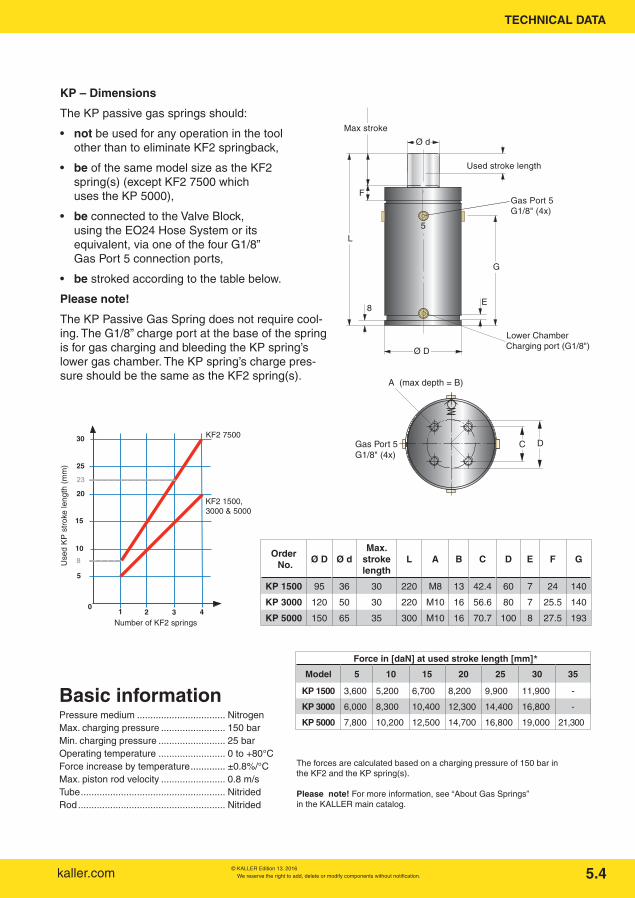
KP – Dimensions
The KP passive gas springs should:
• not be used for any operation in the toolother than to eliminate KF2 springback,
• be of the same model size as the KF2spring(s) (except KF2 7500 whichuses the KP 5000),
• be connected to the Valve Block,using the EO24 Hose System or itsequivalent, via one of the four G1/8”Gas Port 5 connection ports,
• be stroked according to the table below.
Please note!
The KP Passive Gas Spring does not require cool-ing. The G1/8” charge port at the base of the spring is for gas charging and bleeding the KP spring’s lower gas chamber. The KP spring’s charge pres-sure should be the same as the KF2 spring(s).
Pressure medium ................................. NitrogenMax. charging pressure ........................ 150 barMin. charging pressure ......................... 25 bar Operating temperature ......................... 0 to +80°CForce increase by temperature ............. ±0.8%/°CMax. piston rod velocity ........................ 0.8 m/s Tube ...................................................... NitridedRod ....................................................... Nitrided
The forces are calculated based on a charging pressure of 150 bar in the KF2 and the KP spring(s).
Please note! For more information, see “About Gas Springs” in the KALLER main catalog.
A (max depth = B)
Gas Port 5 G1/8" (4x)
C D
Order No.
Ø D Ø dMax.
stroke length
L A B C D E F G
KP 1500 95 36 30 220 M8 13 42.4 60 7 24 140
KP 3000 120 50 30 220 M10 16 56.6 80 7 25.5 140
KP 5000 150 65 35 300 M10 16 70.7 100 8 27.5 193
*
Force in [daN] at used stroke length [mm]
Model 5 10 15 20 25 30 35
KP 1500 3,600 5,200 6,700 8,200 9,900 11,900 -
KP 3000 6,000 8,300 10,400 12,300 14,400 16,800 -
KP 5000 7,800 10,200 12,500 14,700 16,800 19,000 21,300
*
TECHNICAL DATA
Basic information

kaller.comWe reserve the right to add, delete or modify components without notification. © KALLER Edition 13. 2016
Bleeding
Air Port C(Cartridge valve closed when pressurised)
Gas Port 5
Pressure gauge
Air Port C
For connection to Control Block
Gas Port 5
(Cartridge valve closed when pres-surised)
Gas Port 5G 1/4"
Ø7 (2x)
Gas Port 1G 1/4"
Gas Port 3G 1/4"
Gas Port 1G 1/4"
Gas Port 3G 1/4"
Gas Port 5G 1/4"
Air Port C
EZ-Hose Adapter
Air Port C
Evac.Ez hose
Fill. 100
84
114
130
75
Valve block dimensions
Gas Port 5G 1/4"
Ø7 (2x)
Gas Port 1G 1/4"
Gas Port 3G 1/4"
Gas Port 1G 1/4"
Gas Port 3G 1/4"
Gas Port 5G 1/4"
Air Port C
EZ-Hose Adapter
Air Port C
Evac.Ez hose
Fill. 100
84
114
130
75
Gas Port 1G 1/4"
Gas Port 3G 1/4"
Gas Port 5G 1/4"
Gas Port 5G 1/4"
Ø7 (2x)
Air Port C
Bleedvalve
Quick Release coupling
Air Port C
Gas Port 1G 1/4"
Gas Port 3G 1/4"
Pressure Gauge
Evac.Ez hose
Fill. 100
84
130
114
125
75
Gas Port 1G 1/4"
Gas Port 3G 1/4"
Gas Port 5G 1/4"
Gas Port 5G 1/4"
Ø7 (2x)
Air Port C
Bleedvalve
Quick Release coupling
Air Port C
Gas Port 1G 1/4"
Gas Port 3G 1/4"
Pressure Gauge
Evac.Ez hose
Fill. 100
84
130
114
125
75
There are two valve block models available:
• All-in-one valve block,with built-in gas charging andbleeding equipment plus gauge
Order No. 2020801
• Standard valve block,for use with separate control block
Order No. 2120801
For information about how to connect the different valve blocks to a positive lock system, see the installation examples on pages 6.2 and 6.5.
5.5
Charging
TECHNICAL DATA

We reserve the right to add, delete or modify components without notification. © KALLER Edition 13. 2016kaller.com 5.6
Hose and fittings for Ø 6 mm Pneumatic Hose
Material ................................................. PolyurethaneMax. temperature .................................. 60°CMax. pressure ....................................... 16 barColor ..................................................... BlueMin. bend radius ................................... 20 mmHow to order 503377 - XX
Order the length in whole meters
Pneumatic Hose
Ø 6 mm
90° – G 1/8” Order No. 503367
T Connector (hose to hose) Order No. 503368
Y Connector (hose to hose) Order No. 503372
Control system components
AF 13
L
AØ 6
G 1/8"
Ø 6
AF 12
21
33
21
42 13.5
36.5
Straight Connector Order No. (see table)
Order No. A L
503299 G 1/8” 15
503426 G 1/4” 13.5
TECHNICAL DATA
Basic information

kaller.comWe reserve the right to add, delete or modify components without notification. © KALLER Edition 13. 2016
Mechanical Pressure Switch
Order No. 503800
For Tool Integrated Control Systems, the Me-chanical Pressure Switch can be used to control the valve in the KF2 Controllable Gas Spring(s) or Valve Block, for Tool Integrated Control Sys-tems. For more information on Tool Integrated Control Systems see Page 4.2.
Mechanical pressure switches:
• Can control up to 10 pcs KF2 springs.
• Require a constant compressed airsupply (min. 4 bar).
==
==
==
3
1
2
Ø 4(3x)
==
11
5
G 1/8(3x)
Stroke: 5 mmMax. stroke: 8 mm
25
16 16
26
50.5
76.5
24
32
16
5.7
Signal to startreturn for KF2(continous compressed airmin. 4 bar)
Control air signal toKF2 spring(s) (Not recommended to control a Valvebloc )
TECHNICAL DATA
Basic informationFluid …………………… ........................ Air or inert gas,
filtered & lubricatedPressure .............................................. 0 to 10 barTemperature ......................................... –10°C to +60°CFunctions ............................................. 3/2Connection ports ................................. G 1/8” (3×)Flow rate (at 6 bar) …… ....................... 200 l/min

We reserve the right to add, delete or modify components without notification. © KALLER Edition 13. 2016kaller.com
Liquid cooling system components
For applications where cooling is required, each KF2 Controllable Gas Spring must be:
• Fitted with a Cooling Jacket (CJ) (see picture),
• Fitted with a Thermal Relay (Order No. 503388) (see Overheat Protection 4.8),
• Connected in parallel to the Cooler Unit as shown below.
Hose (blue)
Hose (blue)
Hose (red)
AirM
Straight fitting (G1/4")
Non rotable
503406-length
90˚ fitting (G1/4")4017370 4117370
cooling jacket
503395-length
Cooler (10kW or 25 kW) with connection hoses (5 m). Thehoses include quick-couplingsthat attaches to 4117721 and4217721.
Pump
Quick-action coupling (Female)4217721Hose (red)
503396-length
Active springs
503404-length
Distribution block3017359
Quick-action coupling (G 1/2")4117721/4217721or hose fittings (G 1/2")4017723 / 4117723
Connection block3017722
Hose fittings (G 1/2")4017723 / 4117723
A: Hose system for Active SpringsB: Extension
system(optional)
C: Cooler
Quick-action coupling4117721
(Male)
For How To Order information, see KF2 Dimensions 10.5/1.
The cooling fluid is circulated within a closed system through the Cooling Jacket(s), to a Cooler Unit (10kW or 25kW), where heat from the KF2 spring(s) is then dissipated.
5.8
KF2 spring fitted with Cooling Jacket (CJ)
TECHNICAL DATA

kaller.comWe reserve the right to add, delete or modify components without notification. © KALLER Edition 13. 2016
Ø E
G1/2"
AF 27
Connection block 3017722 orDistribution block 3017359
Connection block 3017722 orDistribution block 3017359
Ø 38
G 1/2"
AF 27
70
85
G1/2"
AF 27
Connection block 3017722 orDistribution block 3017359
Connection block 3017722 orDistribution block 3017359
Ø 38
G 1/2"
AF 27
70
85
Male Quick Release Coupling
Order No. 4117721
Female Quick Release Coupling
Order No. 4217721
Connection Block
Order No. 3017722
Cooling System – Hose & Fittings
5.9
= =
Ø 8.5 (x2)
50
40
G 1/2" (x6)115
95
90° Hose Fitting
Straight Hose Fitting
Cooling Hose
AF
AF
C
D
B
AØ E
D
G
Ø E
AF
AF
C
D
B
AØ E
D
G
Ø E
Order No. D A B C E AF
4117370 G 1/4” 23 8 44 16 17
4117723 G 1/2” 30 12 68 23 27
Order No. D E G AF
4017370 G 1/4” 16 28 12
4017723 G 1/2” 23 58 27
Order No. E DN Color Min. bend radius
503406 16 10 Blue 75 mm
503404 16 10 Red 75 mm
503395 23 16 Blue 150 mm
503396 23 16 Red 150 mm
TECHNICAL DATA

We reserve the right to add, delete or modify components without notification. © KALLER Edition 13. 2016kaller.com 5.10
Cooling System – Distribution Block
Order No. 3017359
G 1/2"
View B-B View A-A
B
B
A
A
G 1/4" (10x)G 1/2"
Ø 15 (2x )Ø 9 (2x)
290
45 45 45 45 20
34
260
10 (2x)
60
25
25
60
TECHNICAL DATA

kaller.comWe reserve the right to add, delete or modify components without notification. © KALLER Edition 13. 2016
L
H
1 2
3
4
5
B
78
9
10
12
11
6
13
Liquid Cooling System – Cooler Unit
10 kW Cooler Unit:Order No. ............................................. 4017360 (10 kW) Quick connection .................................. 1/2” H ........................................................... 1,000 L............................................................ 900 B ........................................................... 700 Pump flow ............................................. 40 l/min Tank capacity ........................................ 60 l Electric motor ....................................... 1.5 kW Power supply ........................................ 380 V AC Weight ................................................. 170 kg
Please Note!Do not start the Cooler Unit without cooling fluid in the cooler since this will damage the unit. The unit is equipped with a level/temp switch that will shut down the unit if it leaks or overheats.
Two cooler unit sizes are available:
• 10 kW – Order No. 4017360
• 25 klW – Order No. 4117360 For information on which Cooler Unit is suitable for your application, please fill in the Application Enquiry Form 3.1 and fax it to your local KALLER distributor or directly to Strömsholmen AB.
5.11
1 Pressure gaugeDisplays the system pressure (8-10 bar)
2 Electric motor380 VAC (only)3 Circulation pumpCheck the direction of rotation at start-up
4 Cooling fluid port5 Filter6 User’s Guide7 Cooler8 Cooling fluid outlet
Connect with the supplied 5 m hose and female quick release coupling
9 Power switchOn/Off button
10 Fluid level indicator11 Cooling fluid inlet
Connect with the supplied 5 m hose and male quick release coupling
12 Drainage plug13 Connector 380 V AC, IEC 60309 5 Pin
25 kW Cooler Unit:Order No. ........................................... 4117360 (25 kW) Quick connection .................................. 3/4” H ........................................................... 1,070 L............................................................ 1,070B ........................................................... 890 Pump flow ............................................. 60 l/min Tank capacity ........................................ 90 l Electric motor........................................ 3 kW Power supply ........................................ 380 V AC, IEC 60309 5 PinWeight ................................................. 220 kg
Cooling fluid
The Cooler Unit is not delivered with cooling fluid. We recommend using only ULTRA Safe 620 Cooling Fluid.
For the location of your nearest supplier, please visit www.petrofer.com.
(LC)
TECHNICAL DATA
Basic information Basic information

We reserve the right to add, delete or modify components without notification. © KALLER Edition 13. 2016kaller.com
Nitrogen Cooling System – Nitro CoolerTM (NC)
The Kaller Nitro CoolerTM unit(NC) has been en-gineered to provide Tool Integrated Cooling for Controllable Gas Springs (KF2 or KF2-A) when operating at high production rates.
The Nitro CoolerTM unit (NC) is very compact and provides 1.5 kW of cooling power, with each unit being able to cool up to four KF2 or KF2-A springs.
Gas springs with a special cartridge valve are required to be used with the Nitro CoolerTM unit (NC).
Max. cooling capacity..................... ....... 1.5 kWMax. charge pressure..... ...................... 150 bar at 20°CMin. charge pressure........................ .... 25 barOperating temperature...................... .... 0 to +80 °CWeight.............................................. ..... 16 kgConnection ports...................... ............ G 1/4” (8×)Power supply..................... ................... 24 VDC (22 W)Includes a built-in thermal relay
Nitro CoolerTM Unit (NC) dimensions
One Nitro CoolerTM requires a 24 VDC (22 W) power supply and can be mounted both verti-cally and horizontally, inside or outside the die. Nitro CoolerTM Units are IP64 classed, which makes them resistant to die cleaning.
5.12
Mounting holesØ 6.5 (2x) Mounting holes
Ø 6.5 (2x)
Mounting holeØ 6.5
Mounting holesØ 6.5(2x)
Power Supply Connection
INLET G1/4"(from Gas Port 1)
OUTLET G1/4"(to NP gas port)
250
Gas Connection Port 1G1/4" (6x)
GASINLET
GASOUTLET
120
402
415
90
125
375
170120
Nitro CoolerTM – Order No. 2021641
TECHNICAL DATA
Basic information

kaller.comWe reserve the right to add, delete or modify components without notification. © KALLER Edition 13. 2016
Nitrogen Cooling System – Nitro CoolerTM (NC)
min. 200 mm min. 200 mm
AIR FLOW
Fan Fan Thermal relay (NC)
2+ 4 V DC 0 V DC Signal Signal
Electrical circuitopens at temperature of
> 85 °C
5.13
Base mount
Horizontal mount Vertical mount
TECHNICAL DATA
Mounting possibilities
Nitro Coolers can be mounted both vertically and horizontally. When mounting it is important NOT to restrict the air flow through the cooler. If the air flow is restricted through the Nitro CoolerTM, this will have a negative effect on the cooler’s performance.
Electrical connections
The wiring diagram for the Nitro CoolerTM is depicted below. This diagram can also be found on the label attached to the side of the Nitro CoolerTM next to the connection box.
Please note! The Nitro CoolerTM contains a built-in thermal relay.
The thermal relay circuit is normally closed and opens if the temperature of the relay exceeds 85°C ±5%.
The thermal relay should be connected to the PLC of the press to prevent overheating of the KF2-NC gas spring(s).

We reserve the right to add, delete or modify components without notification. © KALLER Edition 13. 2016kaller.com
KF2/KF2-A 1500
0
10
20
30
40
50
60
70
80
90
100
10 30 50 70 90 110 130 150
Stroke length [mm]
SP
M[s
trok
es/m
inut
e]
1 pc Gas Spring
2 pcs Gas Spring3 pcs Gas Spring4 pcs Gas Spring
Nitrogen Cooling System – Nitro CoolerTM (NC)
KF2/KF2-A 3000
0
10
20
30
40
50
60
70
80
90
100
10 30 50 70 90 110 130 150
Stroke length [mm]
SP
M[s
trok
es/m
inut
e]
1 pc Gas Spring
2 pcs Gas Spring3 pcs Gas Spring4 pcs Gas Spring
KF2/KF2-A 5000
0
10
20
30
40
50
60
70
80
90
100
10 30 50 70 90 110 130 150
Stroke length [mm]
SP
M[s
trok
es/m
inut
e]
1 pc Gas Spring2 pcs Gas Spring3 pcs Gas Spring4 pcs Gas Spring
KF2/KF2-A 7500
0
10
20
30
40
50
60
70
80
90
100
10 30 50 70 90 110 130 150
Stroke length [mm]
SP
M[s
trok
es/m
inut
e]
1 pc Gas Spring2 pcs Gas Spring3 pcs Gas Spring4 pcs Gas Spring
5.14
TECHNICAL DATA
Nitro CoolerTM performance
Depending on how much heat the gas springs in the die generate, it is possible to connect up to four gas springs to one Nitro CoolerTM. The charts on the right display the maximum number of strokes per minute (SPM) allowed when 1, 2, 3 or 4 pcs of KF2/KF2A-NC gas springs, with with a charge pressure of 150 bar, are connected to a single Nitro CoolerTM. Along the four different gas spring curves, the heat generation of the gas springs is 1.5 kW, which is the maximum cooling effect of the Nitro CoolerTM.
Each chart can be used to evaluate how many KF2-NC gas springs can be connected to one Nitro CoolerTM. For any given stroke length, the corresponding SPM rate curve for the number of attached KF2-NC springs, must not be exceeded. The time needed for the return stroke also has to be considered when the SPM is determined for an application.
Important! When using the Nitro CoolerTM, the return stroke speed of the piston rod decreases by approximately 50%. With a distance of 1 m bet-ween the cooler and the gas spring the speeds are as follows:
KF2/KF2-A 1500 – 0.10 m/sec.
KF2/KF2-A 3000 – 0.08 m/sec.
KF2/KF2-A 5000 – 0.05 m/sec.
KF2/KF2-A 7500 – 0.03 m/sec
If a higher speed is needed, please contact your local distributor or Strömsholmen AB.
See example on the next page:

kaller.comWe reserve the right to add, delete or modify components without notification. © KALLER Edition 13. 2016
5.15
Max SPM for one Gas Spring with one Nitro Cooler
0
10
20
30
40
50
60
70
80
90
100
10 30 50 70 90 110 130 150
Stroke length [mm]
SP
M[s
trok
es/m
inut
e]
1 pc Gas Spring
2 pcs Gas Spring3 pcs Gas Spring4 pcs Gas Spring
44
48
Step1
Step2
Step3
Step4
Example:
How to determine the maximum running speed for an application?
We know :
The size used (KF2-1500-048-NC)
The used stroke length (48 mm)
The used pressure (150 bar) (initial force 1.5 ton)
The used number of Gas Springs (2 Gas Springs in this example)
Using the diagram:
Step 1 Choose the correct curve line according to the number of springs used (purple line).
Step 2 According to the used stroke length, go up vertically to the interception point in the diagram (from point 2 to 3).
Step 3 From point 3, read the SPM stroke/minute on the vertical axis (point 4).
Step 4 The value for the maximum used SPM is 44 stroke/min.
For a lower charging pressure, this value should be increased proportionally.
Example: A charging pressure of 100 bar in-creases the maximum used SPM from 44 to 44 × 150/100 = 66 strokes/min.
TECHNICAL DATA

We reserve the right to add, delete or modify components without notification. © KALLER Edition 13. 2016kaller.com
Thermal relay connected
Do not work in the die with the gas springs in locked position. Make sure that the thermal relay is in operation.
Controllable Gas Spring SystemDie No.
Gas spring model
Yes
Stroke length
Max. frequency
Gas spring charge pressure
strokes/min
Min bar Max bar
Strömsholmen ABBox 216, 573 23 SE-Tranås, Swedenwww.kaller.com • [email protected]
The Safer Choice
1. Gas springcharge pressure(max. 150 bar at 20°)
2. Air supplypressure
(min 4 bar, max. 10 bar)
3. Air signals frompress
Standard checks before production run or in the event of malfunction:
Free Information Sign
Order No. 503613
The following Information Sign should be fitted to all tools containing Controllable Gas Springs.
One Information Sign is included with each KF2 order.
5.16
TECHNICAL DATA

kaller.comWe reserve the right to add, delete or modify components without notification. © KALLER Edition 13. 2016
INSTALLATION EXAMPLES
Control System – Standard Lock, KF2
1 3
Filtered & LubricatedControl signal
1
2
3Air Port 4
Air Port 4
Air Port 4
A Standard Lock System requires one control signal.
The KF2 gas springs are delivered with air fittings suitable for Ø 6 mm pneumatic hoses.
Please note! To lock and unlock all KF2 springs simultaneously, the hose lengths from the different springs to the air inlet should all be the same length.
Cut the air hoses to the right length during installation (push-lock system).
The KF2 spring’s control valve should always have a continuous supply of filtered compressed air, with a minimum pressure of 4 bar.
6.1
0
Stroke(mm)
t0 t1 t2
Max press stroke
Max spring stroke
Spring locked
Time
Control signal
t0 t1 t2
Open Closed Open
0
Max press stroke
Max spring stroke
Pres
s
Spring
Open Closed Open
- t0 = Die closed - t1 = Press Bottom Dead Center- t2 = Start of spring return stroke
KF2 spring valve
13
Min 4 bar0 bar
Position Quantity Description Order No. Page
1 3 Controllable Gas Spring KF2 XXXX-XXX 5.1
2 2 T - Connector 503368 5.6
3 1 Pneumatic Hose Ø 6 mm 503377-XX 5.6

We reserve the right to add, delete or modify components without notification. © KALLER Edition 13. 2016kaller.com
Air signalKF2 Spring
1
3
2
Air signalValve Block
Air Port 4
4
Air Port 4
Air Port C
Control System – Positive Lock system, KF2 + KP
A Positive Lock System requires two control signals. One to operate the KF2 gas spring(s) and one to operate the Valve Block
The KF2 gas spring and Valve Block are supplied with air fittings suitable for Ø 6 mm pneumatic hoses.
Please note! To lock and unlock all KF2 springs simultaneously, the hose lengths from the different springs to the air inlet should all be the same length.
Cut the air hoses to the right length during installation (push-lock system). The control valve should always have a continous supply of filtered compressed air, with a minimum pressure of 4 bar.
6.2
t0 t1 t2
Min 4 bar0 bar
Min 4 bar0 bar
0
Stroke(mm)
Spring locked
Time0
Max press stroke
Max spring stroke
Pres
s
Spring
t0 t1 t2
50
Position Quantity Description Order No. Page
1 2 Controllable Gas Spring KF2 XXXX-XXX 5.1
2 1 All-in-one Valve Block 2020801 5.5
3 2 T Connector 503368 5.6
4 1 Pneumatic Hose Ø 6 mm 503377-XX 5.6
INSTALLATION EXAMPLES

kaller.comWe reserve the right to add, delete or modify components without notification. © KALLER Edition 13. 2016
Hose System – Standard Lock, KF2
1 3
1
2
3
6
2
4
5
Gas Port 1Gas Port 3
Gas Port 1 Gas Port 3
2
2
Gas Port 1 Gas Port 3
(3x)
(4x)
To charge, bleed and check the gas pressure for a Standard Lock in a KF2 gas spring system, all springs should be connected to a standard Control Block (here shown connected via a Coupling Block).
We recommend the EZ Hose system and fittings be used for such systems. The KF2 gas springs are delivered with Gas Ports 1 and 3 plugged. When connecting the EZ Hose system, the charging valve in Port 1 of each KF2 gas spring must first be removed. Each G 1/8” Gas Port, for both the KF2 Gas Spring and Coupling Block, requires an adapter (4114973-G 1/8”) for connection to EZ Hose.
The Control Block should be placed higher than the KF2 springs to avoid loss of internal oil when bleeding.
Method using Coupling Block(s)
6.3
Position Quantity Description Order No. Page
1 3 Controllable Gas Spring KF2 XXXX-XXX 5.1
2 7 Adapter G 1/8” 4114973-G 1/8” Gas Link Systems in the Main Catalog
3 3 EZ Hose straight – 90 4017568-XXXX Gas Link Systems in the Main Catalog
4 1 EZ Hose straight – straight 4014974-XXXX Gas Link Systems in the Main Catalog
5 1 Control Block 3116114-01 Gas Link Systems in the Main Catalog
6 1 Multi-Coupling Block 4017032 Gas Link Systems in the Main Catalog
INSTALLATION EXAMPLES

We reserve the right to add, delete or modify components without notification. © KALLER Edition 13. 2016kaller.com
1 3
1
23
4 5
Gas Port 1 Gas Port 3
Gas Port 1Gas Port 3
Gas Port 1Gas Port 3
2
2
2
Twin Gas Port 1 (not available for KF2 1500)
Twin Gas Port 3 (not available forKF2 1500)
Twin Gas Port 1(not available forKF2 1500)
Twin Gas Port 3(not available forKF2 1500)
2
(2x)
Hose System – Standard Lock, KF2
To charge, bleed and check the gas pressure for a Standard Lock in a KF2 gas spring system, all springs should be connected to a standard Control Block. These hoses are connected using the KF2’s twin gas ports to the Control Block. We recommend the EZ Hose System and fittings be used for such systems. The KF2 gas springs are delivered with Gas Ports 1 and 3 plugged. When connect-ing the EZ Hose system, the charging valve in Port 1 of each KF2 gas spring must first be removed. Each G 1/8” Gas Port, for both the KF2 Gas Spring and Coupling Block, requires an adapter (4114973-G 1/8”) for connection to EZ Hose. The Control Block should be placed higher than the KF2 springs to avoid loss of internal oil when bleeding.
Method using Twin Ports
(Not valid for KF2 1500)
6.4
Position Quantity Description Order No. Page
1 3 Controllable Gas Spring KF2 XXXX-XXX 5.1
2 5 Adapter G 1/8” 4114973-G 1/8” Gas Link Systems in the Main Catalog
3 2 EZ Hose straight – 90 4017568-XXXX Gas Link Systems in the Main Catalog
4 1 EZ Hose straight – straight 4014974-XXXX Gas Link Systems in the Main Catalog
5 1 Control Block 3116114-01 Gas Link Systems in the Main Catalog
INSTALLATION EXAMPLES

kaller.comWe reserve the right to add, delete or modify components without notification. © KALLER Edition 13. 2016
1
9
3
4
13
5
2
8
9
5
10
8
Gas Port 1Gas Port 3
Gas Port 5
Gas Port 1
Gas Port 3
Gas Port 1
Gas Port 3
11
6
9
6
8
7
Gas Port 1Gas Port 3
Position Quantity Description Order No. Page
1 4 Controllable Gas Spring KF2 XXXX-XXX 5.1
2 1 KP Passive Spring KP XXXX 5.4
3 2 Control Block 3116114-01 Main Catalog
4 1 Standard Valve Block 2120801 5.5
5 2 Multi-Coupling Block G 1/8” 3015044 Main Catalog
6 2 EO24 Adapter G 1/4” 504144 Main Catalog
7 1 EZ Adapter G 1/4” 4014973-G 1/4” Main Catalog
8 10 EO24 Adapter G 1/8” 503593 Main Catalog
9 10 EZ Adapter G 1/8” 4114973-G 1/8” Main Catalog
10 6 EO24 Hose straight - 90° 3220857-xxxx Main Catalog
11 7 EZ Hose straight - straight 4014974-xxxx Main Catalog
Hose System – Positive Lock system, KF2 + KP
Positive Lock, KF2 + KP As indicated above, perform gas charging and bleeding as follows:
Step 1
Charge the lower gas chamber in the KP Passive Gas Spring via the Control Block (3)*.
Step 2
Charge the KF2 Standard spring(s) and upper chamber of the KP gas spring via the Control Block (3) connected to the standard Valve Block (4).
To connect KF2 Controllable Gas Spring(s) to a KP – Pas-sive Gas Spring via the Valve Block, two hose connections are needed:
• One EZ Hose connection
• One EO24 Hose connection.
The Control Block should be placed higher than the springs to avoid loss of internal oil when bleeding.
Example 1
6.5
*
INSTALLATION EXAMPLES
We reserve the right to add, delete or modify components without notification. © KALLER Edition 13. 2016kaller.com
1
2
10
11 6
Gas Port 5
10
8
12
3
47
12
5
Gas Port 3Gas Port 1
Twin Gas Port 1
Gas Port 1Gas Port 3
Twin Gas Port 1
Twin Gas Port 3
Gas Port 1
8
13
9
9
13
9
7
Filtered & LubricatedControl signal
Filtered & LubricatedControl signal
Filtered & LubricatedControl signal
Filtered & LubricatedControl signal
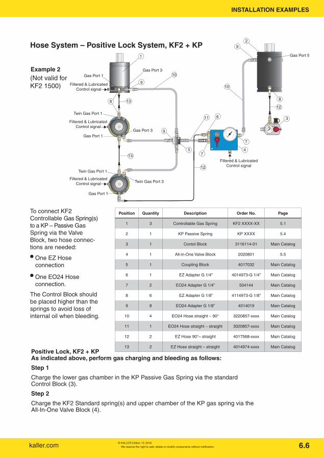
Position Quantity Description Order No. Page
1 3 Controllable Gas Spring KF2 XXXX-XX 5.1
2 1 KP Passive Spring KP XXXX 5.4
3 1 Contol Block 3116114-01 Main Catalog
4 1 All-in-One Valve Block 2020801 5.5
5 1 Coupling Block 4017032 Main Catalog
6 1 EZ Adapter G 1/4” 4014973-G 1/4” Main Catalog
7 2 EO24 Adapter G 1/4” 504144 Main Catalog
8 6 EZ Adapter G 1/8” 4114973-G 1/8” Main Catalog
9 8 EO24 Adapter G 1/8” 4014019 Main Catalog
10 4 EO24 Hose straight – 90° 3220857-xxxx Main Catalog
11 1 EO24 Hose straight – straight 3020857-xxxx Main Catalog
12 2 EZ Hose 90°– straight 4017568-xxxx Main Catalog
13 2 EZ Hose straight – straight 4014974-xxxx Main Catalog
Hose System – Positive Lock System, KF2 + KP
Example 2
Positive Lock, KF2 + KP As indicated above, perform gas charging and bleeding as follows:
Step 1
Charge the lower gas chamber in the KP Passive Gas Spring via the standard Control Block (3).
Step 2
Charge the KF2 Standard spring(s) and upper chamber of the KP gas spring via the All-In-One Valve Block (4).
6.6
(Not valid forKF2 1500)
To connect KF2 Controllable Gas Spring(s) to a KP – Passive Gas Spring via the Valve Block, two hose connec-tions are needed:
• One EZ Hoseconnection
• One EO24 Hose connection.
The Control Block should be placed higher than the springs to avoid loss of internal oil when bleeding.
INSTALLATION EXAMPLES

kaller.comWe reserve the right to add, delete or modify components without notification. © KALLER Edition 13. 2016
Position Quantity Description Order No. Page
1 3 Controllable Gas spring KF2 XXXX-XXXX NC 5.1
2 6 EO24 Adapter G 1/8” 503593 Main Catalog
3 2 EO24 Adapter G 1/4” 504144 Main Catalog
4 2 EZ Adapter G 1/4” 4014973-G 1/4” Main Catalog
5 3 EO24 Hose straight – straight 3020857-xxxx Main Catalog
6 3 EO24 Hose straight – 90o 3020857-xxxx Main Catalog
7 1 EZ Hose straight – straight 4014974-xxxx Main Catalog
8 1 Control Block 3116114-01 Main Catalog
9 1 Nitro Cooler Block 2021641 5.12
KF2 connection – NC Standard lock with a Nitro CoolerTM
1
1
1
2
2
2
2
2
2
3
3
4
7
5
5
5
6
6
6
8
9
Air to lock
Air to lock
Air to lock
Signal from Thermal RelayPower Supply Connection
6.7
When using a Nitro CoolerTM, only EO24 hoses should be used. There is a gas transport between the cooler and gas springs with every stroke. Therefore the Nitro CoolerTM should be placed as close as possible to the springs to minimize the length of the hoses.
The Nitro CoolerTM includs heat protection, thus eliminating the need for thermal relays at the springs.
The control block for charging and bleeding can be connected optionally to one of the existing port 2 on the springs or tto the Nitro CoolerTM.
INSTALLATION EXAMPLES

We reserve the right to add, delete or modify components without notification. © KALLER Edition 13. 2016kaller.com
Position Quantity Description Order No. Page
1 3 Controllable Gas Spring KF2 XXXX-XXXX NC 5.1
2 14 EO24 Adapter G 1/8” 503593 Main Catalog
3 8 EO24 Adapter G 1/4” 504144 Main Catalog
4 1 EZ Adapter G 1/4” 4014973-G 1/4” Main Catalog
5 6 EO24 Hose straight – straight 3020857-xxxx Main Catalog
6 5 EO24 Hose straight – 90o 3020857-xxxx Main Catalog
7 2 EZ Hose straight - straight 4014974-xxxx Main Catalog
8 1 Control Block 3116114-01 Main Catalog
9 1 Nitro Cooler Block 2021641 5.12
10 1 Multi-Coupling Block G 1/8” 3015044 Main Catalog
11 2 EZ Adapter G 1/8” 4114973-G 1/8” Main Catalog
12 1 All-in-One Valve Block 2020801 5.5
13 1 KP Passive Spring KP xxxx 5.4
KF2-NC connection – Positive lock with a Nitro CoolerTM
2
2
3
5
7
6
6
3
59
Air to lock
Air to lock
Air to lock
Signal from Thermal RelayPower Supply Connection
6
6
1
1
22
3
5
5
5
2
2
2
2
1
11
10
2
2
6
2
13
4
312
11
7
8
2
6.8
When using a Nitro CoolerTM for a positive lock system, the requirement are the same as for a standard lock system.(See previous page.)
INSTALLATION EXAMPLES

kaller.comWe reserve the right to add, delete or modify components without notification. © KALLER Edition 13. 2016
Position Quantity Description Order No. Page
1 4 Controllable Gas spring KF2 XXXX-XXXX NC 5.1
2 8 EO24 Adapter G 1/8” 503593 Main Catalog
3 9 EO24 Adapter G 1/4” 504144 Main Catalog
4 5 EO24 Hose straight – straight 3020857-xxxx Main Catalog
5 4 EO24 Hose straight – 90o 3020857-xxxx Main Catalog
6 1 L Coupling 504147 Main Catalog
7 1 Control Block 3116114-02 Main Catalog
8 1 Nitro Cooler Block 2021641 5.12
Connection of four KF2-1500-NC Standard Locks with a Nitro CoolerTM
1
1
2
2 4
Air to lock
Air to lock
Air to lock
Air to lock
Top View
1
1
2
3
5
4
5
5 4
4
3
3
2
2
4
5
6
8
7
Signal from Thermal RelayPower Supply Connection
6.9
INSTALLATION EXAMPLES

We reserve the right to add, delete or modify components without notification. © KALLER Edition 13. 2016kaller.com 7.1
General
What air pressure is required to ope-rate the cartridge valves?
4 bar minimum air pressure is required to close the normally open (NO) cartridge valves.
What is the maximum air pressure allowed to operate the cartridge val-ves?
10 bar maximum air pressure is allowed to operate the cartridge valves.
What service life can I expect from a KF2 Controllable Gas Spring?
As long as the thermal relay is used, the following service lifetimes can be expected:For stroke lengths up to 50 mm: 0.5 million strokes. For stroke lengths above 50 mm: 50,000 stroke me-ters.
Can I use other Hose Systems? We cannot guarantee the function of the system if Hose Systems other than those mentioned in this manual are used. Please contact your local Kaller distributor or Strömsholmen AB directly for more informa-tion.
Can I combine different KF2 size springs in the same system?
No. Please contact your local KALLER distributor or Strömsholmen AB directly for more information.
FREQUENTLY ASKED QUESTIONS (FAQ’S)

kaller.comWe reserve the right to add, delete or modify components without notification. © KALLER Edition 13. 20167.2
Relating to Standard Lock, KF2
Is it possible to adjust the stroke length of the KF2 spring, or must I always use 100% of the nominal stroke ±0.5 mm?
There are 2 versions of the KF2 Controllable Gas Spring, the standard model KF2 and an adjustable model KF2-A. For more information on the adjustable model, see Technical Data page 5.2.
How fast can the KF2 spring be stroked?
0.8 m/sec is the maximum allowed compression velo-city. The maximum stroke frequency (spm) at which a KF2 spring can operate at depends on the stroke length of the spring and level of cooling. See Cooling (optional) on page 4.5 for more information.
What can I do to eliminate KF2 springback?
If you are using 100% stroke length ±0.5 mm of the KF2 spring, a maximum springback f 1 mm can be expected. It is possible to eliminate this at any time by conver-ting the Standard Lock into a Positive Lock System. Please contact your local Kaller distributor or Ströms-holmen AB directly for more information.
Can I lock a KF2 Controllable Gas Spring at any position?
Basically yes, but the less you stroke the KF2 Controllable Gas Spring, the greater the springback will be. Please contact your local Kaller distributor or Strömsholmen AB directly for more information.
FREQUENTLY ASKED QUESTIONS (FAQ’S)

We reserve the right to add, delete or modify components without notification. © KALLER Edition 13. 2016kaller.com
Relating to Positive Lock System, KF2+KP
How many KF2 Controllable Gas Springs can be connected to a single KP Passive Gas Spring?
Up to 4 pcs KF2 can be connected to a single KP spring.
How many Valve Blocks do I need in the system?
One Valve Block is required for each KP Passive Gas Spring in the system.
Can I use the KP spring in the tool for forming?
No. The KP spring is not to be used for any operation in the tool; use it only to eliminate KF2 springback.
Can I use just the EZ Hose System to connect to my Positive Lock System?
No. The EO24 Hose System (or its equivalent) must be used between the KF2 spring(s), Valve Block and KP Passive Gas Spring.
Can I use just the EO24 Hose System to connect to my Positive Lock System?
Yes.
7.3
FREQUENTLY ASKED QUESTIONS (FAQ’S)

kaller.comWe reserve the right to add, delete or modify components without notification. © KALLER Edition 13. 2016
Relating to Liquid Cooling
Is Cooling always required? Not always. Generally speaking, longer stroke lengths and faster press stroke frequencies normally require cooling. See Cooling System (optional) on page 4.5 for more information.
How many KF2 controllable springs can be connected to a single Cooler Unit?
The maximum heat effect for all springs combined has to be lower than the cooling effect of the cooler. If a group of springs whose combined heat factor exceeds the maximum heat factor for the ”Nitro CoolerTM used for 1pc KF2 spring ” (see page 4.6), please secure according to the diagrams on page 5.14.
Can I use my own cooling system? Yes. It is possible to use the cooling system from the press or other coolers.
What different cooling fluids can we use?
We recommend use of Water-glycol fluid (HFC) UL-TRA SAFE 620. ULTRA-SAFE 620 is approved by all major equipment manufacturers and is often used for running in new machines. Equivalents to this water-glycol fluid can be used, but Strömsholmen AB cannot be held responsible for poor function.
7.4
FREQUENTLY ASKED QUESTIONS (FAQ’S)

We reserve the right to add, delete or modify components without notification. © KALLER Edition 13. 2016kaller.com
Relating to Nitro CoolerTM
How many KF2 can be connected to one Nitro CoolerTM?
Depending on how much heat is generated in a parti-cular application, up to four gas springs can be connec-ted to one Nitro CoolerTM. See table on page 5.14
Can we elminate the decrease in return speed caused by the Nitro CoolerTM ?
No. When using the Nitro CoolerTM, gas is transported between the cooler and gas springs for every press stroke, and consequently the return speed will be af-fected. With a distance of 1 m between the cooler and gas spring the speeds are as follows: KF2/KF2-A 1500 – 0.12 m/sec.KF2/KF2-A 3000 – 0.10 m/sec.KF2/KF2-A 5000 – 0.08 m/sec.KF2/KF2-A 7500 – 0.05 m/sec. return stroke speed.If a higher speed is needed, please contact your local distributor or Strömsholmen AB.
How many Nitro CoolersTM can be used in one die?
There is no limitation as long as there is sufficiently ventilated places for them in the die.
7.5
FREQUENTLY ASKED QUESTIONS (FAQ’S)

kaller.comWe reserve the right to add, delete or modify components without notification. © KALLER Edition 13. 2016
System Problem Solution
Standard Lock, KF2
KF2 spring does not lock
Make sure the KF2 spring’s Air Port 4 has mini-mum 4 bar air pressure before press BDC
Check that all hose connections are correct
KF2 piston rod’s springback is greater
than 1 mm
Make sure 100% of the KF2 spring’s nominal stroke length ±0.5 mm is used
Make sure the KF2 spring’s Air Port 4 has mini-mum 4 bar air pressure before press BDC
KF2 piston rod does not return
Make sure the KF2 spring’s Air Port 4 has zero air pressure when required to open
Check for any obstructions in the tool preventing piston rod return
Check that there is gas pressure in the KF2 spring
System Problem Solution
Positive Lock System,
KF2 + KP
KF2 spring does not lock
Make sure the KF2 spring’s Air Port 4 has mini-mum 4 bar air pressure before press BDC
Check that all hose connections are correct
KF2 piston rod’s spring back is greater
than 0 mm
Make sure the cartridge valve in the Valve Block is closed during the press’ down-stroke and that the KP-Passive Gas Spring is being stroked suf-ficiently for this application
Make sure 100% of the KF2 spring’s nominal stroke length ±0.5 mm is used
Check that the cartridge valve in the Valve Block opens at BDC
KF2 piston rod does not return
Make sure the KF2 spring’s Air Port 4 has zero air pressure when required to open
Check for any obstructions in the tool preventing piston rod return
Check that there is gas pressure in the KF2 spring
TROUBLESHOOTING
7.6

We reserve the right to add, delete or modify components without notification. © KALLER Edition 13. 2016kaller.com
APPENDIXAPPENDIX
The guide in the KF2-A is made up of the following main components:
8.1
Feel free to download an animated guide from our homepage: www.kaller.com
Example 1:
The stroke length should be increased with 4 mm from the nominal stroke length.
Solution: Open the spring and guide, remove the 4 mm thick spacer. The 1 mm and 2 mm thick spacers should be left in the guide/spring. The procedure is described on the next page.
Table1
Important!
• Only fully trained personnel with experience in servicing gas springs areallowed to adjust to the stroke length.
• Make sure the work surface where you will be working on the KF2-A spring(s) is clean and free from contaminates.
• Make sure there is no gas pressure in the KF2-A spring before proceeding.
Stroke length adjustment of KF2-A
The guide length and stroke length of the spring can be adjusted by installing and/or removing spacers between the upper and lower guide. To obtain the correct stroke length, install spacers in the guide according to Table 1.
To adjust from nominal stroke length
Spacer (mm)
Stroke length 1 2 4 8
Maximum +7 0 0 0 0
+6 1 0 0 0
+5 0 1 0 0
+4 1 1 0 0
+3 0 0 1 0
+2 1 0 1 0
+1 0 1 1 0
*Nominal 0 1 1 1 0
-1 0 0 0 1
-2 1 0 0 1
-3 0 1 0 1
-4 1 1 0 1
-5 0 0 1 1
-6 1 0 1 1
-7 0 1 1 1
Minimum -8 1 1 1 1
* The nominal stroke length is always marked on the tube
Ex.1
Spacers 1 mm of thickness 2 mm of thickness 4 mm of thickness 8 mm of thickness
(not shown)
Lower Guide
Upper Guide
Dust Cover for nominal stroke ≥ 20 mm

kaller.comWe reserve the right to add, delete or modify components without notification. © KALLER Edition 13. 2016
APPENDIX
1: Make sure the KF2-A gas spring is degassed and remove the dust cover (if applicable).
3: Remove the Upper Guide and install the combination of Spacers that will give you the required stroke length.
4: Install the Upper Guide and use the mount-ing sleeve and plastic hammer again to knock down the guide to expose the lock ring groove.
7: Charge the KF2-A spring with nitrogengas, and fit the dust cover (if applicable).
8.2
Work procedure
2: Knock down the guide and remove the lock ring by using a mounting sleeve and a plastic hammer.
5: Install the lock ring and pull up the piston rod assembly using a T-handle.
6: Make sure that the guide is flush with the top of the tube. (If not, check the installation of the lock ring.)
Stroke length adjustment of KF2-A
Upper guide
Lock ring
Spacers
Install the lock ring and pull up the piston rod assembly using a T-handle.

We reserve the right to add, delete or modify components without notification. © KALLER Edition 13. 2016kaller.com
APPENDIX
1 3
42 4 2
New KF2
Old KF
New Block
Gas Port 1
Gas Port 3
Air Port 2Air Port 4
Gas Port 1
Gas Port 3Air Port 4
How does the new KF2 differ from an existing KF
The KF2 is fitted with a normally open (NO) cartridge valve, which has the following advantages:
• Simplified control system
• Combined charge & bleed port
• Low-pressure variant LP is now obsolete
• Only 4 bar air pressure required
How to fit the new KF2 to existing KF systems
KF2 Controllable Gas Springs are completely interchangeable with existing KF springs.
1 3
42
New KF2
Old KF
Gas Port 1
Gas Port 3
Air Port 4
Gas Port 1
Gas Port 3
Air Port 2Air Port 4
Standard Lock Example: Replacing an existing KF with a new KF2To replace an existing KF spring with a new KF2 spring in a Standard Lock System, simply plug the air signal that went to the KF springs Air Con-nection Port 2 (shown here by an X).
Positive Lock System Example: Replacing an existing KF with a new KF2To replace an existing KF spring with a new KF2 spring in a Positive Lock System, simply plug the air signal that went to the KF springs Air Connection Port 2 (shown here by an X).
8.3

kaller.comWe reserve the right to add, delete or modify components without notification. © KALLER Edition 13. 2016
APPENDIX
Model Ø D Ø d max. H Ø K V Ø P R Order No. K Lug
KF2/KF2-A -1500 130 8 10 50 60 17.5 20 2 pcs K-3000*
KF2/KF2-A -3000 155 8 10 95 30 17.5 25 2 pcs K-5000
KF2/KF2-A -5000 195 12 10 110 30 21.5 25 2 pcs K-7500
KF2/KF2-A -7500 240 12 10 120 30 21.5 29 2 pcs K-10000
For upside down installations, the threaded holes in the base of the KF2/KF2-A should always be used when mounting the Controllable Gas Springs to the tool.
For upright installations, an alternative is to mount the Controllable Gas Springs using two K Lugs in combination with dowel pins, as shown below. The dowel pins will engage the threaded holes in the bottom of the spring (M12 and M16, respectively) and will prevent the spring from moving out of posi-tion even if the lugs would come loose. The dowel pins will also ensure that the springs are installed in the correct position.
KF2/KF2-A Alternative Mounting
K-Lugs
R
Ø K
Ø DA
A
V 47°Ø P
5x45˚(2x)
It is also possible to mount the KF2/KF2-A Controllable Gas Springs using an FCSC flange mount if cooling is not required. For more information contact your local KALLER distributor or Strömsholmen AB.
8.4
FCSC Top mount
* Please note, K-3000 lugs will require a slight modification, according to the sketch before they can befitted to the KF2/KF2-A 1500.
H
Ø d max. (2×)ØK
Dowel pins
A - A
Modification of K-3000 Lug