Products: Millenium and Millenium Plus- UL Version … · Layouts #2-8 in Section 2—Sample...
117
Products: Millenium and Millenium Plus- UL Version A publication of Millennium Group, Inc. 9 Tech Circle Natick, MA 01760 Printed in USA, 2006 Copyright © Millennium Group, Inc. 2006 All rights reserved No part of this book may be reproduced or transmitted in any form or by any means, electronic or mechanical, including photocopying, recording, or by any information storage and retrieval system, without prior written permission from the Publisher. The information contained in this publication is accurate to the best of Millennium Group’s knowledge. Specifications are subject to change without notice. 047-100960 (07/06)
Transcript of Products: Millenium and Millenium Plus- UL Version … · Layouts #2-8 in Section 2—Sample...

Products: Millenium and Millenium Plus- UL Version A publication of Millennium Group, Inc. 9 Tech Circle Natick, MA 01760 Printed in USA, 2006 Copyright © Millennium Group, Inc. 2006 All rights reserved No part of this book may be reproduced or transmitted in any form or by any means, electronic or mechanical, including photocopying, recording, or by any information storage and retrieval system, without prior written permission from the Publisher. The information contained in this publication is accurate to the best of Millennium Group’s knowledge. Specifications are subject to change without notice. 047-100960 (07/06)

________________________________________________________________
This Page Intentionally Left Blank
INSTALLATION MANUAL
SECTION OVERVIEW
SECTION SAMPLE MILLENIUM LAYOUTS
Layout 1: Up to 100 DCDs at a Single Site ..................................................... 3
Layout 2: Single Site with more than 100 DCDs............................................ 5
Layout 3: More than 100 DCDs on multiple floors ........................................ 7
Layouts 4-7: Dial-Up Modem Configurations................................................. 9
Layout 8: Leased Lines to Sites.................................................................... 15
SECTION ELECTRICAL SPECIFICATIONS
• Door Control Devices (DCDs) .........................................................2-6 Inputs......................................................................................................................... 3 Input Shunting ........................................................................................................... 4 Request-to-Exit (R.E.X.)............................................................................................ 5 Strikes and Suppression ........................................................................................ 5-6
• Relay Control Devices (RCDs) ........................................................... 7 • Site Controller Units (SCUs) ............................................................... 8 • Power Supply.....................................................................................9-12
Location .......................................................................................................... 10 Wire/Cable Sizes & Limits ....................................................................................... 10 Communication Line Conditioner ............................................................................ 10 Lost AC for Power Supply ....................................................................................... 11 Grounding .......................................................................................................... 11 Lightning .......................................................................................................... 11 Power Supply (with distribution board) drawing ...................................................... 12
SECTION WIRING REQUIREMENTS & DIAGRAMS A. Wire/Cable Sizes & Limits ..........................................................................2-4
• PC—to—Site Controller (M+) ..................................................................... 2 • TIU–to–Site Controller (M+) ........................................................................ 2 • Power Supply—to—Power Supply
Power Supply—to—Trunk Interface Unit (TIU) Power Supply—to—Site Controller (M+).............................................. 3
• Power Supply—to—DCD or RCD ............................................................ 4 • DCD to Reader Devices (Leader Cable) ....................................................... 5
® E L E C T R O N I C A C C E S S C O N T R O L
• Inputs ............................................................................................................ 5 • Relays ............................................................................................................ 5
B. How to Select Wire Sizes (with Cable Charts) ........................................... 7 C. Wiring Diagrams.........................................................................................9-16
• DCD–to–DCD ......................................................................................................... 10 • DCD to Readers ................................................................................................ 11-12 • Standard Millenium ............................................................................................... 13 • Power Supply–to–Power Supply ......................................................................... 14 • (Site Controller & Modem)...................................................................................... 15 • (Site Controller with TIU) ........................................................................................ 16
SECTION CONNECTIONS A. Reader Device Connections.......................................................................1-3 B. Door Control Devices (DCDs)....................................................................4-8 C. Relay Control Devices (RCDs) ..............................................................10-14 D. Trunk Interface Units (TIUs) ...................................................................15-16 E. Site Controller Units (SCUs)...................................................................17-24 F. Shielded Cable Connections (Communications) ................................25-29
SECTION PREPARING DOORS & INSTALLING READERS
• Keylok Rotation Adjustment ................................................................................... 1-2 A. Preparing Doors ...........................................................................................3-6
• Solid Wood Doors (Mortise Locks)......................................................................... 3-4 • Hollow Frame Glass Doors (Mortise Locks)........................................................... 5-6
B. Installing Readers ......................................................................................7-14
• Rim Cylinder Keylok .................................................................................................. 7 • Key-in-Knob Keylok................................................................................................ 8-9 • Panel Mount Keylok or Keyreader........................................................................... 10 • Gang Mount Keyreader ........................................................................................... 11 • Gang Mount Touch Reader..................................................................................... 12 • Mullion Mount Keyreader ........................................................................................ 13 • Other Reader Devices............................................................................................. 14
C. Hinge Installation......................................................................................15-17
SECTION GLOSSARY
SECTION LIST OF FIGURES

Millenium Installation Manual ©
Section 1— Overview 1
Millenium® System Overview
This manual covers installation practices for Millenium Entry, Expert, and Enterprise access control systems. Please refer to the respective User Manual for the system you are installing for software setup instructions. The installation process involves four basic phases:
1. Wiring of electrical components 2. Connecting circuit boards and making board settings 3. Preparing doors and installing access reader units 4. Fine-tuning configurations and programming access control through
the appropriate Millenium software. The first three phases are covered in this manual. Some references are made in this installation manual to software settings (phase 4), but the majority of fine-tuning configurations through Millenium software is contained in the individual User Manuals for the respective Millenium systems.
NOTE: This system has not been investigated by Underwriters Laboratories (UL) as a burglary alarm system. All inputs shall be used to monitor only the door position. Major components of Millenium systems • Door Control Device (DCD)
• Access Entry Readers (in a wide choice of styles)
• Relay Control Device (RCD)
• Trunk Interface Unit (TIU) (not UL listed)
• Power Supply
• PC Computer (not UL listed) with Millenium system software
• RS-232 wedge keyreader for reading Marlok keys into the computer
• Site Controller Unit (SCU)
Installations with remote sites or individual sites requiring more than 100 DCDs require: (1) one Site Controller (SCU) for each 100 DCDs.
NOTE: This system is a stand-alone system, and any computer or receiving equipment has not been investigated by UL. Devices that are not UL Listed should not be used in conjunction with UL-Listed systems.
Door Control Devices (DCDs) A Door Control Device (DCD) is a circuit board which contains all information required to make access decisions for its door. Because Millenium is a true distributed database system, the PC does not have to be on-line for
Millennium Group, Inc
Section 1— Overview 2
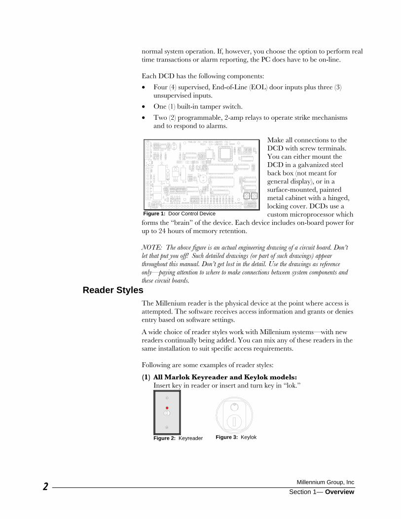
normal system operation. If, however, you choose the option to perform real time transactions or alarm reporting, the PC does have to be on-line. Each DCD has the following components:
• Four (4) supervised, End-of-Line (EOL) door inputs plus three (3) unsupervised inputs.
• One (1) built-in tamper switch.
• Two (2) programmable, 2-amp relays to operate strike mechanisms and to respond to alarms.
Make all connections to the DCD with screw terminals. You can either mount the DCD in a galvanized steel back box (not meant for general display), or in a surface-mounted, painted metal cabinet with a hinged, locking cover. DCDs use a custom microprocessor which
forms the “brain” of the device. Each device includes on-board power for up to 24 hours of memory retention. NOTE: The above figure is an actual engineering drawing of a circuit board. Don’t let that put you off! Such detailed drawings (or part of such drawings) appear throughout this manual. Don’t get lost in the detail. Use the drawings as reference only—paying attention to where to make connections between system components and these circuit boards.
Reader Styles The Millenium reader is the physical device at the point where access is attempted. The software receives access information and grants or denies entry based on software settings.
A wide choice of reader styles work with Millenium systems—with new readers continually being added. You can mix any of these readers in the same installation to suit specific access requirements. Following are some examples of reader styles:
(1) All Marlok Keyreader and Keylok models: Insert key in reader or insert and turn key in “lok.”
Figure 1: Door Control Device
Figure 2: Keyreader
Figure 3: Keylok
Millenium Installation Manual ©
Section 1— Overview 3
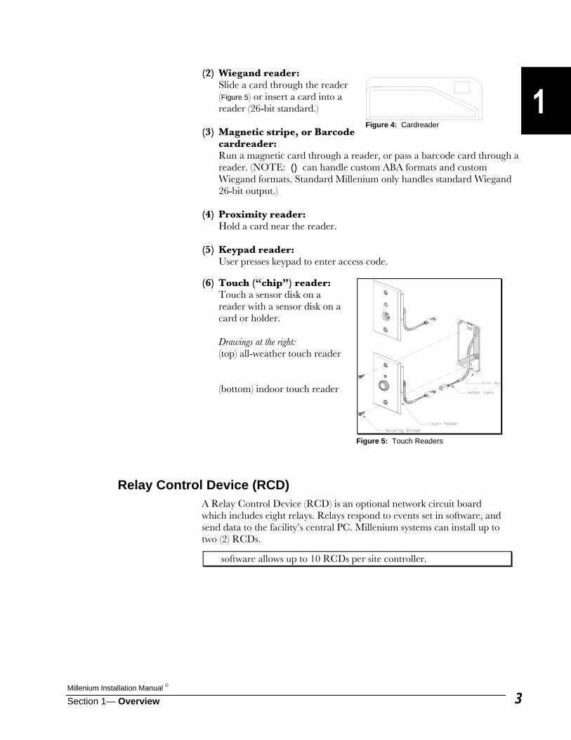
(2) Wiegand reader: Slide a card through the reader
(Figure 5) or insert a card into a reader (26-bit standard.)
(3) Magnetic stripe, or Barcode
cardreader: Run a magnetic card through a reader, or pass a barcode card through a
reader. (NOTE: () can handle custom ABA formats and custom Wiegand formats. Standard Millenium only handles standard Wiegand 26-bit output.)
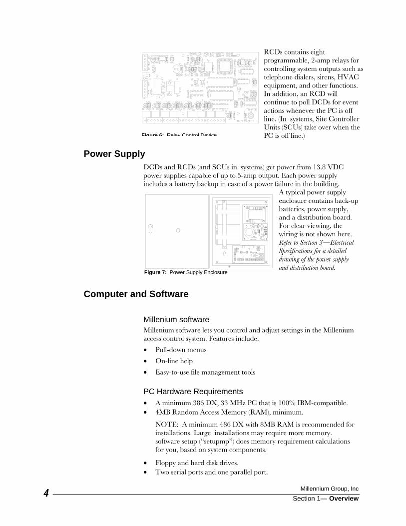
(4) Proximity reader: Hold a card near the reader. (5) Keypad reader: User presses keypad to enter access code. (6) Touch (“chip”) reader: Touch a sensor disk on a
reader with a sensor disk on a card or holder.
Drawings at the right: (top) all-weather touch reader (bottom) indoor touch reader
Relay Control Device (RCD) A Relay Control Device (RCD) is an optional network circuit board which includes eight relays. Relays respond to events set in software, and send data to the facility’s central PC. Millenium systems can install up to two (2) RCDs.
software allows up to 10 RCDs per site controller.
Figure 4: Cardreader
Figure 5: Touch Readers
Millennium Group, Inc
Section 1— Overview 4
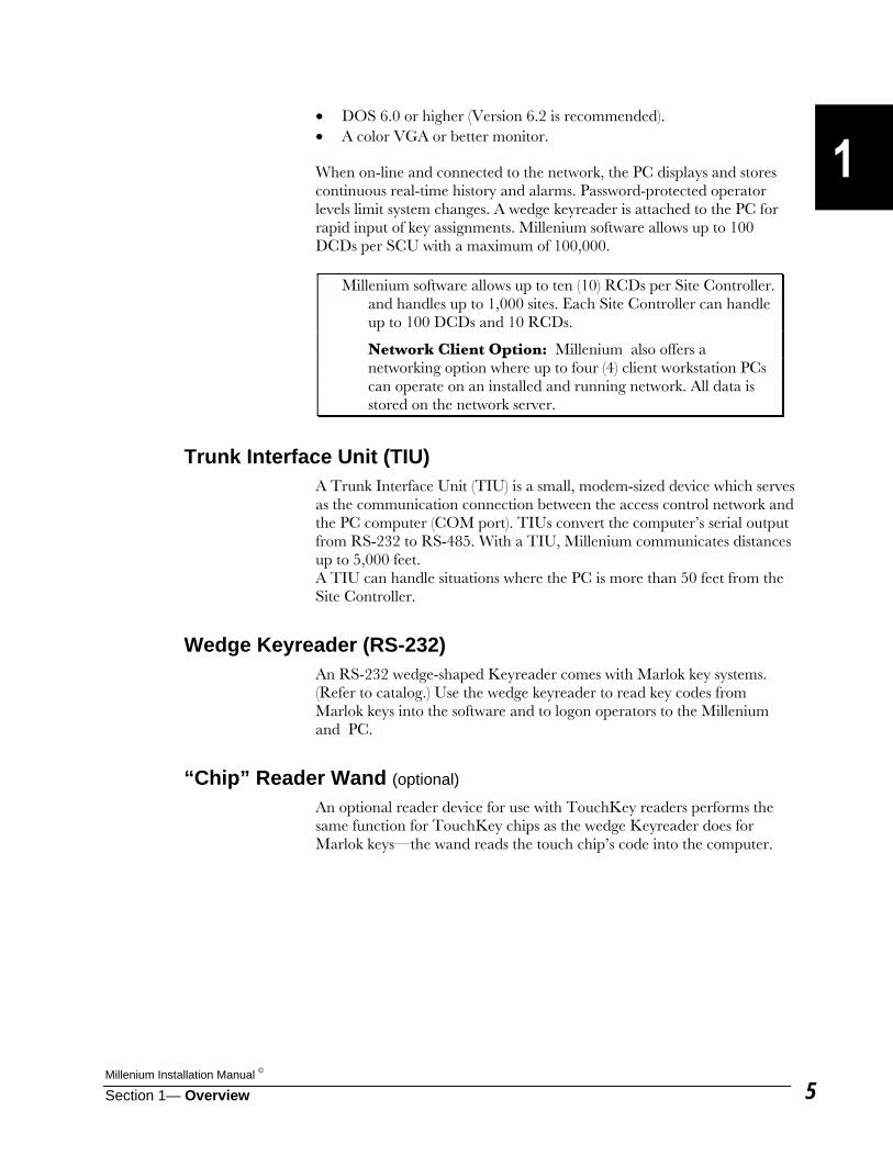
RCDs contains eight programmable, 2-amp relays for controlling system outputs such as telephone dialers, sirens, HVAC equipment, and other functions. In addition, an RCD will continue to poll DCDs for event actions whenever the PC is off line. (In systems, Site Controller Units (SCUs) take over when the PC is off line.)
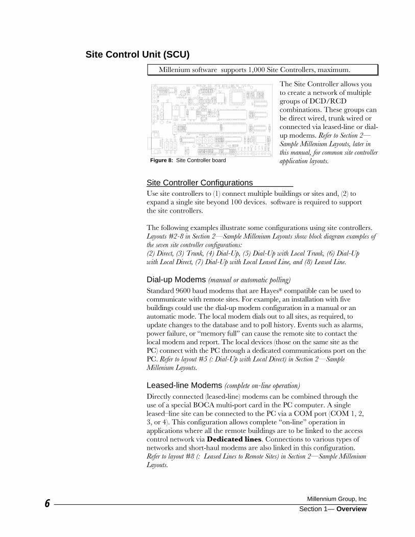
Power Supply DCDs and RCDs (and SCUs in systems) get power from 13.8 VDC power supplies capable of up to 5-amp output. Each power supply includes a battery backup in case of a power failure in the building.
A typical power supply enclosure contains back-up batteries, power supply, and a distribution board. For clear viewing, the wiring is not shown here. Refer to Section 3—Electrical Specifications for a detailed drawing of the power supply and distribution board.
Computer and Software Millenium software Millenium software lets you control and adjust settings in the Millenium access control system. Features include:
• Pull-down menus
• On-line help
• Easy-to-use file management tools PC Hardware Requirements • A minimum 386 DX, 33 MHz PC that is 100% IBM-compatible. • 4MB Random Access Memory (RAM), minimum.
NOTE: A minimum 486 DX with 8MB RAM is recommended for installations. Large installations may require more memory. software setup (“setupmp”) does memory requirement calculations for you, based on system components.
• Floppy and hard disk drives. • Two serial ports and one parallel port.
Figure 6: Relay Control Device
Figure 7: Power Supply Enclosure
Millenium Installation Manual ©
Section 1— Overview 5
• DOS 6.0 or higher (Version 6.2 is recommended). • A color VGA or better monitor.
When on-line and connected to the network, the PC displays and stores continuous real-time history and alarms. Password-protected operator levels limit system changes. A wedge keyreader is attached to the PC for rapid input of key assignments. Millenium software allows up to 100 DCDs per SCU with a maximum of 100,000.
Millenium software allows up to ten (10) RCDs per Site Controller. and handles up to 1,000 sites. Each Site Controller can handle up to 100 DCDs and 10 RCDs.
Network Client Option: Millenium also offers a networking option where up to four (4) client workstation PCs can operate on an installed and running network. All data is stored on the network server.
Trunk Interface Unit (TIU) A Trunk Interface Unit (TIU) is a small, modem-sized device which serves as the communication connection between the access control network and the PC computer (COM port). TIUs convert the computer’s serial output from RS-232 to RS-485. With a TIU, Millenium communicates distances up to 5,000 feet. A TIU can handle situations where the PC is more than 50 feet from the Site Controller.
Wedge Keyreader (RS-232) An RS-232 wedge-shaped Keyreader comes with Marlok key systems. (Refer to catalog.) Use the wedge keyreader to read key codes from Marlok keys into the software and to logon operators to the Millenium and PC.
“Chip” Reader Wand (optional) An optional reader device for use with TouchKey readers performs the same function for TouchKey chips as the wedge Keyreader does for Marlok keys—the wand reads the touch chip’s code into the computer.
Millennium Group, Inc
Section 1— Overview 6
Site Control Unit (SCU) Millenium software supports 1,000 Site Controllers, maximum.
The Site Controller allows you to create a network of multiple groups of DCD/RCD combinations. These groups can be direct wired, trunk wired or connected via leased-line or dial-up modems. Refer to Section 2—Sample Millenium Layouts, later in this manual, for common site controller application layouts.
Site Controller Configurations
Use site controllers to (1) connect multiple buildings or sites and, (2) to expand a single site beyond 100 devices. software is required to support the site controllers. The following examples illustrate some configurations using site controllers. Layouts #2-8 in Section 2—Sample Millenium Layouts show block diagram examples of the seven site controller configurations: (2) Direct, (3) Trunk, (4) Dial-Up, (5) Dial-Up with Local Trunk, (6) Dial-Up with Local Direct, (7) Dial-Up with Local Leased Line, and (8) Leased Line. Dial-up Modems (manual or automatic polling) Standard 9600 baud modems that are Hayes® compatible can be used to communicate with remote sites. For example, an installation with five buildings could use the dial-up modem configuration in a manual or an automatic mode. The local modem dials out to all sites, as required, to update changes to the database and to poll history. Events such as alarms, power failure, or “memory full” can cause the remote site to contact the local modem and report. The local devices (those on the same site as the PC) connect with the PC through a dedicated communications port on the PC. Refer to layout #5 (: Dial-Up with Local Direct) in Section 2—Sample Millenium Layouts. Leased-line Modems (complete on-line operation) Directly connected (leased-line) modems can be combined through the use of a special BOCA multi-port card in the PC computer. A single leased–line site can be connected to the PC via a COM port (COM 1, 2, 3, or 4). This configuration allows complete “on-line” operation in applications where all the remote buildings are to be linked to the access control network via Dedicated lines. Connections to various types of networks and short-haul modems are also linked in this configuration. Refer to layout #8 (: Leased Lines to Remote Sites) in Section 2—Sample Millenium Layouts.
Figure 8: Site Controller board

Millenium Installation Manual ©
Section 1— Overview 7
Trunk Interface Unit (TIU) (allows on-line operation) Multiple site controllers can be attached via a 4-wire trunk in applications where more than 100 devices are connected to one PC. For example, a multi-story office building can use a TIU with a Site Controller to run two twisted-pair wires greater distances (5,000 feet maximum) between floors. This “trunk” configuration also allows for “on-line” operation. Refer to layout #3 (: Trunk) to see a single building with more than 100 DCDs. (Section 2—Sample Millenium Layouts)
NOTES: (1) A Glossary at the end of this manual defines terminology used both in the installation and in the Millenium and ( ) software.
(2) Elevator control installation is covered in a separate booklet (P/N 047-101192), shipped with the elevator systems (not investigated by UL.)

Millennium Group, Inc
Section 1— Overview 8
This Page Intentionally Left Blank
Millenium Installation Manual ©
Section 2— Sample Millenium Layouts 1
Sample Millenium® Layouts
Millenium layouts can be grouped into the following general types:
Sample diagrams of the above layout types appear on the following pages, but many layout variations exist beyond the examples shown here. Layout components are briefly described below. Refer to Section 1—Overview for more information on components. Refer to Section 3—Electrical Specifications, and Section 4—Wiring Requirements for wiring for details on cable sizes/types/limitations and wiring diagrams. Power Supply The power supply is commercial, regulated, filtered, and surge-protected with an output of 13.8 volts. Total current for all wire runs from each power supply must not exceed 5 amps. Most installations require more than one power supply. Door Control Devices (DCDs) The DCD is the primary element of the system because it feeds door access control data to the PC. Each device comes with relays and door inputs described in Section 3—Electrical Specifications and Section 4—Wiring Requirements. NOTE: Each power supply can support up to 20 to 30 DCDs, depending on the site and reader requirements, whether or not you use doors with magnetic locks/strikes, and other factors. Check with the factory for guidance when considering this higher range. Relay Control Device (RCD) You can use a maximum ten (10) RCDs with each installation. Relays on the RCD allow you to set up other controls for equipment that may or may not be access-control related such as HVAC equipment. In other words, you would not normally use RCDs to control doors. Each RCD comes with relays and backups as described in Section 3—Electrical Specifications and Section 4—Wiring Requirements. RCDs offer the following features: • Time zone activation • Timed activation or timed release of 0 to 255 seconds
Layout #1: Millenium at a single site with up to 100 DCDs
Layout #2 at a single building with more than 100 DCDs
Layout #3 at a single building with more than 100 DCDs and more than 50 feet between the PC and the Site Controllers
Layouts #4-7 with dial-up modem connection to remote sites including three dial-up combinations
Layout #8 with leased-line connection to remote sites
Millennium Group, Inc.
Section 2— Sample Millenium Layouts 2
Trunk Interface Unit (TIU) TIUs handle communications between the central computer and the Millenium access control device network. Modem configurations handle the communications in most configurations except Enterprise applications.
Site Controller Unit (SCU) Site Controllers serve the following functions:
• connect multiple buildings or remote sites via modem • expand a single site to handle more than 100 Door Control Devices.
Millenium systems require at least one Site Controller Unit along with software. Each SCU manages groups of up to 100 DCDs (and up to 10 RCDs). software handles up to 1,000 sites.
Site Controllers handle communications from the Personal Computer (PC) to the access control network through either of two connectors, depending on how the individual application is set up. Seven possible communication configurations exist: 1. Direct 2. Trunk 3. (Modem) Dial-Up 4. (Modem) Dial-Up with Local Direct 5. (Modem) Dial-Up with Local Trunk 6. (Modem) Dial-Up with Local Leased Line 7. (Modem) Leased Line NOTE: Site Controller communication configurations must also be set in the software.
• “setupmp” program, • under the OPTIONS menu, • in the CONNECT TO SITES field. Configuration options are covered in more detail in Section 5—Connections, under the Site Controller Unit section.
Millenium Installation Manual ©
Section 2— Sample Millenium Layouts 3
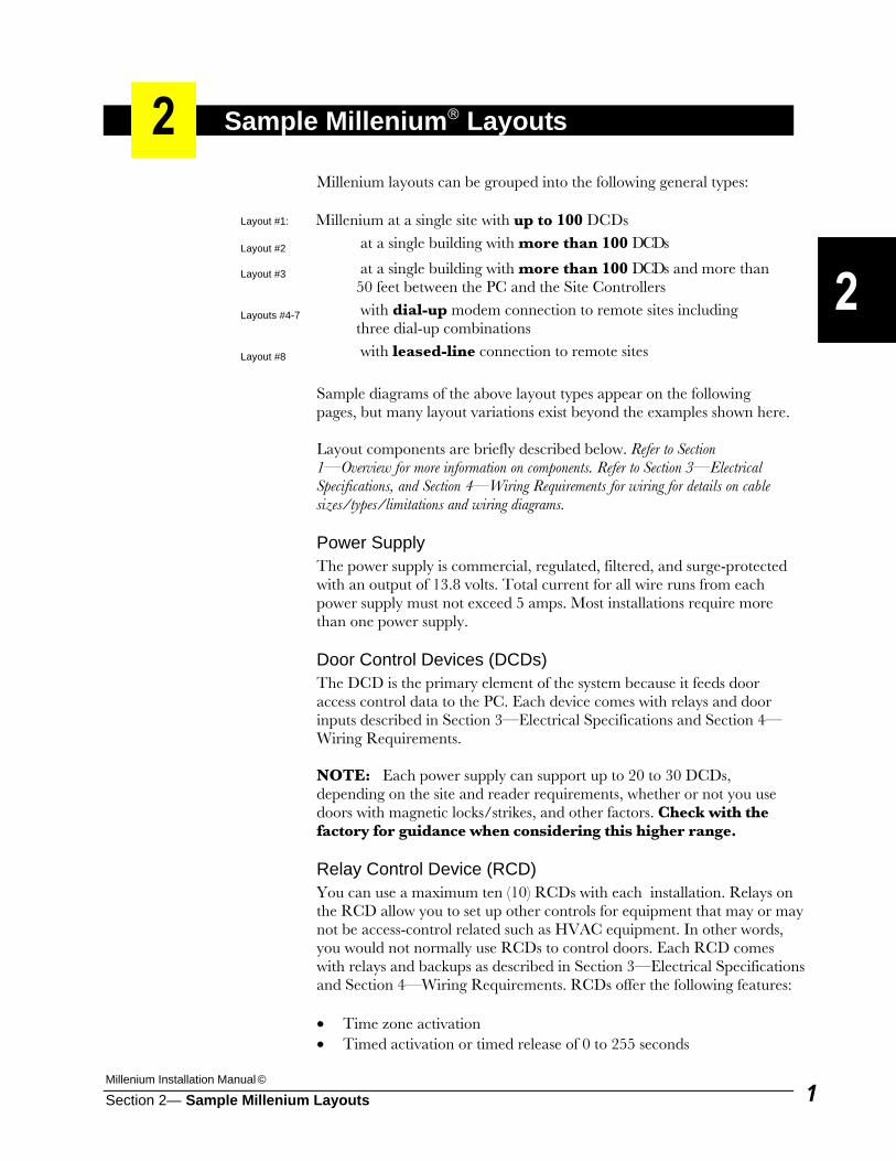
Layout 1: Up to 100 DCDs at a Single Site You can install up to 100 (*) door control devices (DCDs) and up to two (2) relay control devices (RCDs). RCDs can control additional functions at the site such as lighting systems, surveillance cameras, sirens, sprinkler systems, and/or HVAC equipment. A trunk interface unit (TIU) communicates PC output to the Millenium network. (*) Each power supply can furnish power for as few as 5 to a maximum of
20-30 control devices (depending on the site and reader requirements). Since a single Power Supply handles up to 5 amps total current, additional power supplies are often required. Refer to Power Supply in Section 4—Electrical Specifications.
RS-232 Wedge
Keyreader PC with Millenium
software Trunk
Interface Unit (TIU)
Power Supply with Line
Conditioner DCD DCD DCD Power to 5-30 DCDs per power supply. ( * )
Power Supply DCD DCD DCD
COMMUNICATIONS
1 pair-22AWG Twisted & Shielded
Cable length limit = 5,000 ft.
POWER—13.8 VDC 2-Conductor—12AWG
Power Supply RCD DCD DCD
To control a READER. Reader device types include:
Keylok Magnetic Keyreader Touch Keypad Proximity
To control equipment such as HVAC Maximum of two (2) optional Relay Control Devices per standard Millenium system.
Millenium (DOS)
2 pair-22AWG Shielded
(One pair –Ground, one pair– Communications.
A six-conductor Leader Cable, supplied by Marlok, connects Marlok reader devices to Door Control Devices (DCDs). • Keyreader/Keylok cable length limit = 15
feet (recommended). MAXIMUM length = 35 feet (as long as cable is not bundled with other wires)
Longer runs and/or certain reader types require SHIELDED cable: • Cardreader cable runs greater than 50 feet
require SHIELDED leader cable. (Cardreader cable length limit = 500 feet.)
• Touch (“chip”) readers require special Marlok SHIELDED leader cable.
(Touch reader cable length limit = 35 feet.) • Proximity readers require SHIELDED
leader cable.
#1
Layout 1: Single Site (Up to 100 DCDs)

Millennium Group, Inc.
Section 2— Sample Millenium Layouts 4
This Page Intentionally Left Blank
Millenium Installation Manual ©
Section 2— Sample Millenium Layouts 5
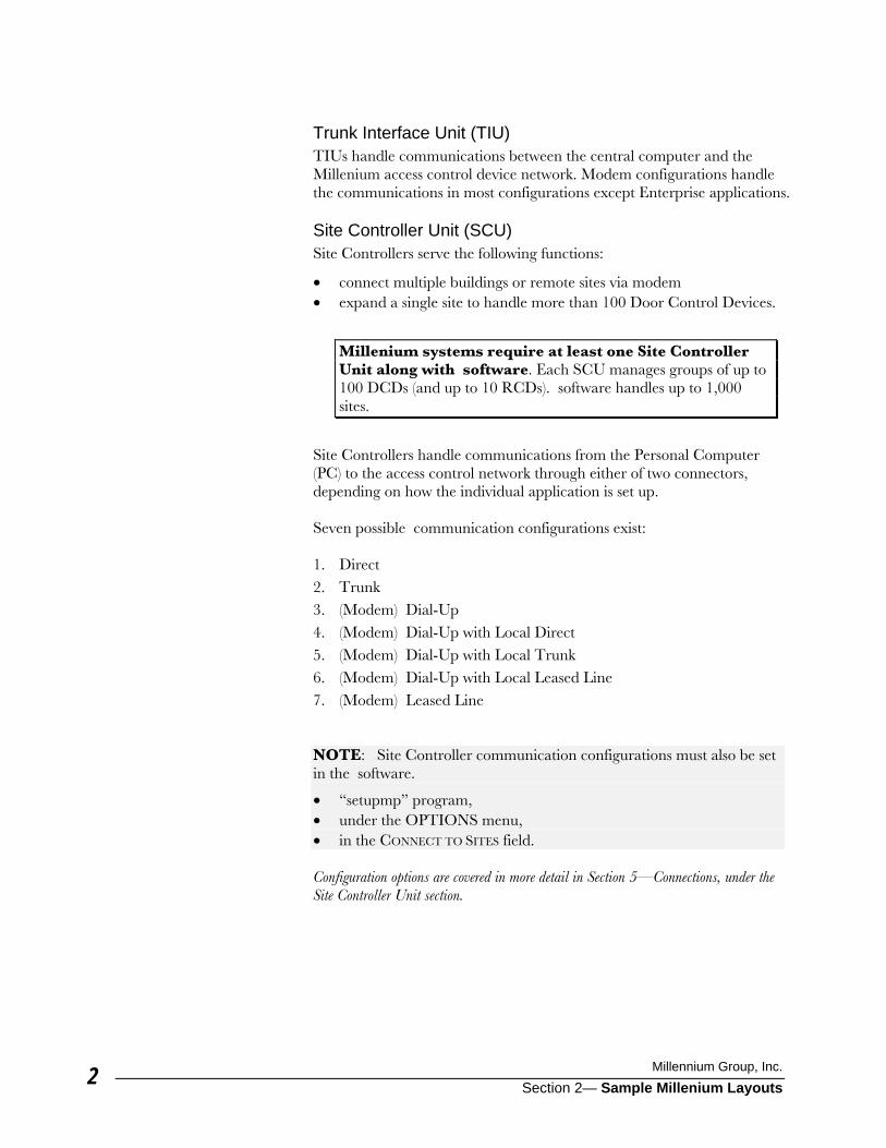
Layout 2: Single Site with more than 100 DCDs
() Use when requirements call for more than 100 DCDs and up to ten RCDs. Each Site Controller unit (SCU) requires at least one power supply with line conditioner, and each Site Controller handles up to 100 control devices. This example shows a direct configuration to more than 100 DCDs. Distance from PC to SCU cannot exceed 50 feet. (Distances over 50 feet require a TIU as illustrated next in the Layout 3.)
(*) Each power supply can furnish power for as few as 5 to a maximum of 20-30 control devices (depending on the site and reader requirements). Since a Power Supply handles up to 5 amps total current, additional power supplies are often required. Refer to Power Supply in Section 4—Electrical Specifications.
PC with Millenium Plus
software
Power Supply with Line
Conditioner DCD DCD DCD Power to 5-30 DCDs per power supply. ( * )
Power Supply with Line
Conditioner RCD DCD DCD
(more than 100 DCDs)
“setupmp” = DIRECT
SITE Controller Unit (SCU)
SCU
SCU
POWER—13.8 VDC 1 pair-12 AWG
COMMUNICATIONS 1 pair-22 AWG
Twisted & Shielded Cable length maximum = 5,000 ft.
Power Supply with Line
Conditioner RCD DCD DCD
J3 RS-232
J3 RS-232
J3-DB9RS-232
2 pair-22 AWG Shielded
(One pair –Ground, one pair– Communications.)
RS-232 Wedge
Keyreader
( * ) Maximum number of DCDs per Power Supply depends on total current required. All wire runs from a single power supply cannot exceed 5 amps total current.
(Refer to Power Supply Section 3—Electrical
ifi i )
Cable Pinouts for Direct
COM PORT J3 DB9 DB-9 DB-25 2 RXD 3 TXD 2 TXD 3 TXD 2 RXD 3 RXD 5 GND 5 GND 7 GND
50 Feet –Maximum Distance
Power Supply with Line
Conditioner RCD DCD DCD
SCU
J3 RS-232
#2
Layout 2: DIRECT communications configuration

Millennium Group, Inc.
Section 2— Sample Millenium Layouts 6
This Page Intentionally Left Blank
Millenium Installation Manual ©
Section 2— Sample Millenium Layouts 7
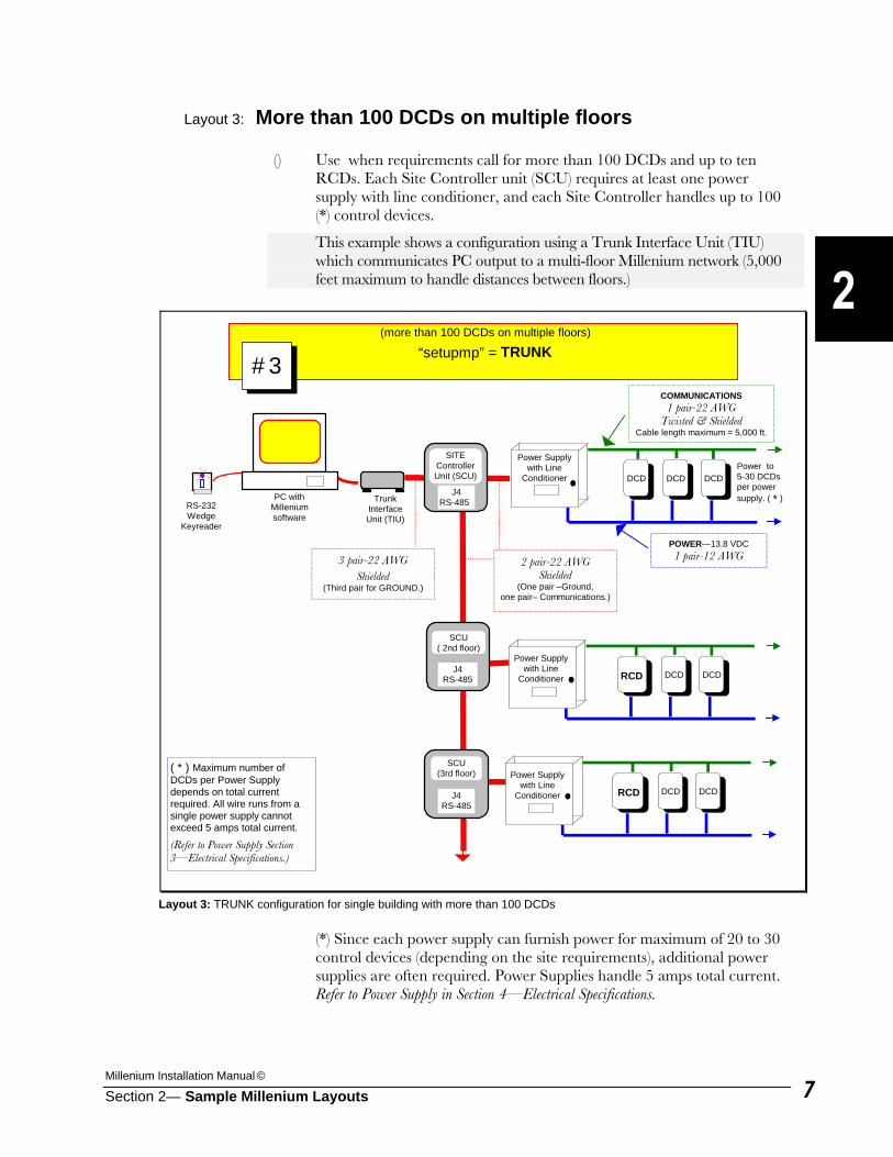
Layout 3: More than 100 DCDs on multiple floors
() Use when requirements call for more than 100 DCDs and up to ten RCDs. Each Site Controller unit (SCU) requires at least one power supply with line conditioner, and each Site Controller handles up to 100 (*) control devices.
This example shows a configuration using a Trunk Interface Unit (TIU) which communicates PC output to a multi-floor Millenium network (5,000 feet maximum to handle distances between floors.)
(*) Since each power supply can furnish power for maximum of 20 to 30 control devices (depending on the site requirements), additional power supplies are often required. Power Supplies handle 5 amps total current. Refer to Power Supply in Section 4—Electrical Specifications.
PC with Millenium software
Power Supply with Line
Conditioner DCD DCD DCDPower to 5-30 DCDs per power supply. ( * )
Power Supply with Line
Conditioner RCD DCD DCD
(more than 100 DCDs on multiple floors)
“setupmp” = TRUNK
SITE Controller Unit (SCU)
SCU ( 2nd floor)
SCU (3rd floor)
POWER—13.8 VDC 1 pair-12 AWG
COMMUNICATIONS 1 pair-22 AWG
Twisted & Shielded Cable length maximum = 5,000 ft.
Power Supply with Line
Conditioner RCD DCD DCD
J4 RS-485
J4 RS-485
J4 RS-485
2 pair-22 AWG Shielded
(One pair –Ground, one pair– Communications.)
RS-232 Wedge
Keyreader
( * ) Maximum number of DCDs per Power Supply depends on total current required. All wire runs from a single power supply cannot exceed 5 amps total current.
(Refer to Power Supply Section 3—Electrical Specifications.)
Trunk Interface Unit (TIU)
3 pair-22 AWG Shielded
(Third pair for GROUND.)
#3
Layout 3: TRUNK configuration for single building with more than 100 DCDs

Millennium Group, Inc.
Section 2— Sample Millenium Layouts 8
This Page Intentionally Left Blank
Millenium Installation Manual ©
Section 2— Sample Millenium Layouts 9
Layouts 4-7: Dial-Up Modem Configurations
Use when requirements call for remote sites in the access control network. Dial-up setups require the central computer to “poll” remote sites to communicate data, either manually or automatically at designated times. Dial-up capability is not available with Millenium Enterprise since it is usually installed on a network. Configurations vary depending on access control and site requirements. The software has four settings for possible Dial-up configurations: (1) DIALUP:
PC is connected to remote sites by dial-up modem. PC is in separate location and is not connected to any local access control devices.
Dial-Up Combinations: (2) DIAL-UP with LOCAL DIRECT:
PC is connected, both locally to one or more Site Controllers and remotely to a Site Controller via dial-up modem. At local location, distance from PC to Site Controller is less than 50 feet.
(3) DIAL-UP with LOCAL TRUNK:
PC is connected, both locally to one or more Site Controllers and remotely to one or more Site Controllers via dial-up modem. At local location, distance from PC to Site Controller is more than 50 feet—so a Trunk Interface Unit (TIU) is required.
(4) DIAL-UP with LOCAL LEASED LINE:
PC is connected, both locally to one or more Site Controllers via leased-line modem and remotely to one or more Site Controllers via dial-up modem.
Millennium Group, Inc.
Section 2— Sample Millenium Layouts 10
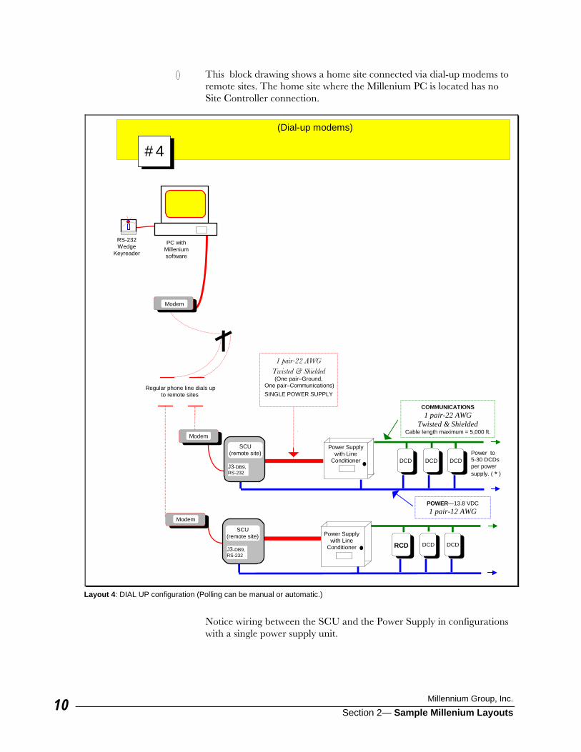
() This block drawing shows a home site connected via dial-up modems to remote sites. The home site where the Millenium PC is located has no Site Controller connection.
Notice wiring between the SCU and the Power Supply in configurations with a single power supply unit.
(Dial-up modems)
PC with Millenium software
Power Supply with Line
Conditioner RCD DCD DCD
1 pair-22 AWG Twisted & Shielded (One pair–Ground,
One pair–Communications)SINGLE POWER SUPPLY
SCU (remote site)
SCU (remote site)
Regular phone line dials up to remote sites
Modem
Modem
Modem
J3-DB9, RS-232
J3-DB9, RS-232
RS-232 Wedge
Keyreader
Power Supply with Line
Conditioner DCD DCD DCD Power to 5-30 DCDs per power supply. ( * )
POWER—13.8 VDC 1 pair-12 AWG
COMMUNICATIONS 1 pair-22 AWG
Twisted & Shielded Cable length maximum = 5,000 ft.
#4
Layout 4: DIAL UP configuration (Polling can be manual or automatic.)
Millenium Installation Manual ©
Section 2— Sample Millenium Layouts 11
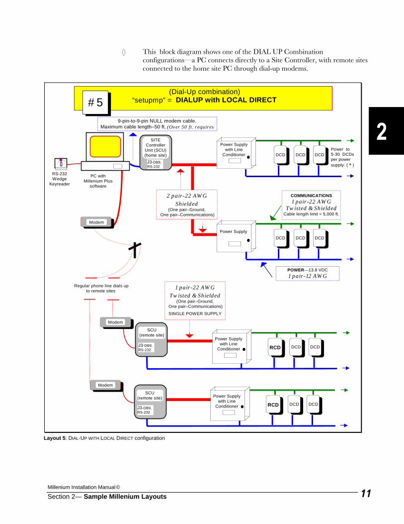
() This block diagram shows one of the DIAL UP Combination configurations—a PC connects directly to a Site Controller, with remote sites connected to the home site PC through dial-up modems.
PC with Millenium Plus
software
Power Supply with Line
Conditioner DCD DCD DCD Power to 5-30 DCDs per power supply. ( * )
Power Supply DCD DCD DCD
Power Supply with Line
Conditioner RCD DCD DCD
(Dial-Up combination) “setupmp” = DIALUP with LOCAL DIRECT
SITE Controller Unit (SCU)(home site)
SCU (remote site)
SCU (remote site)
Regular phone line dials up to remote sites
POWER—13.8 VDC 1 pair-12 AWG
COMMUNICATIONS 1 pair-22 AWG
Twisted & ShieldedCable length limit = 5,000 ft.
Power Supply with Line
Conditioner RCD DCD DCD
Modem
Modem
Modem
J3-DB9, RS-232
J3-DB9, RS-232
9-pin-to-9-pin NULL modem cable. Maximum cable length–50 ft. (Over 50 ft. requires
RS-232 Wedge
Keyreader
J3-DB9, RS-232
#5
2 pair-22 AWG Shielded
(One pair–Ground, One pair–Communications)
1 pair-22 AWG Twisted & Shielded
(One pair–Ground, One pair–Communications)
SINGLE POWER SUPPLY
Layout 5: DIAL-UP WITH LOCAL DIRECT configuration
Millennium Group, Inc.
Section 2— Sample Millenium Layouts 12
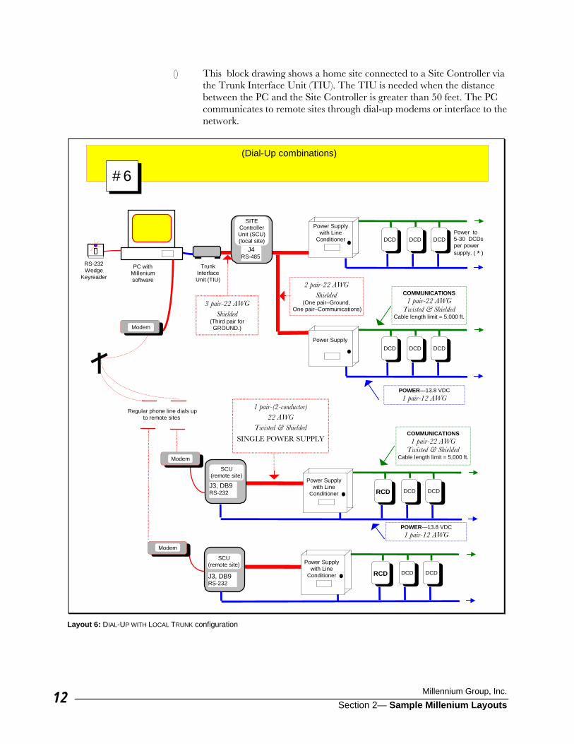
() This block drawing shows a home site connected to a Site Controller via the Trunk Interface Unit (TIU). The TIU is needed when the distance between the PC and the Site Controller is greater than 50 feet. The PC communicates to remote sites through dial-up modems or interface to the network.
(Dial-Up combinations)
PC with Millenium software
Power Supply with Line
Conditioner DCD DCD DCD Power to 5-30 DCDs per power supply. ( * )
Power Supply DCD DCD DCD
Power Supply with Line
Conditioner RCD DCD DCD
2 pair-22 AWG Shielded
(One pair–Ground, One pair–Communications)
SITE Controller Unit (SCU)(local site)
SCU (remote site)
SCU (remote site)
Regular phone line dials up to remote sites
POWER—13.8 VDC 1 pair-12 AWG
COMMUNICATIONS 1 pair-22 AWG
Twisted & Shielded Cable length limit = 5,000 ft.
Power Supply with Line
Conditioner RCD DCD DCD
Modem
Modem
Modem
J3, DB9 RS-232
J3, DB9 RS-232
RS-232 Wedge
Keyreader
J4 RS-485
Trunk Interface Unit (TIU)
#6
1 pair-(2-conductor) 22 AWG
Twisted & Shielded
SINGLE POWER SUPPLY
COMMUNICATIONS 1 pair-22 AWG
Twisted & Shielded Cable length limit = 5,000 ft.
POWER—13.8 VDC 1 pair-12 AWG
3 pair-22 AWG Shielded
(Third pair for GROUND.)
Layout 6: DIAL-UP WITH LOCAL TRUNK configuration
Millenium Installation Manual ©
Section 2— Sample Millenium Layouts 13
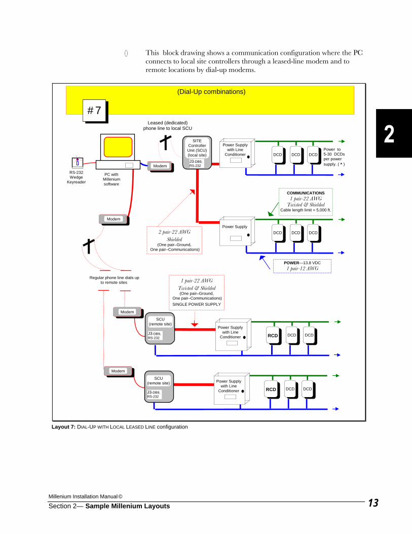
() This block drawing shows a communication configuration where the PC connects to local site controllers through a leased-line modem and to remote locations by dial-up modems.
(Dial-Up combinations)
PC with Millenium software
Power Supply with Line
Conditioner DCD DCD DCD Power to 5-30 DCDs per power supply. ( * )
Power Supply DCD DCD DCD
Power Supply with Line
Conditioner RCD DCD DCD
2 pair-22 AWG Shielded
(One pair–Ground, One pair–Communications)
SITE Controller Unit (SCU)(local site)
SCU (remote site)
SCU (remote site)
Regular phone line dials up to remote sites
POWER—13.8 VDC 1 pair-12 AWG
COMMUNICATIONS 1 pair-22 AWG
Twisted & Shielded Cable length limit = 5,000 ft.
Power Supply with Line
Conditioner RCD DCD DCD
Modem
Modem
Modem
J3-DB9, RS-232
J3-DB9, RS-232
RS-232 Wedge
Keyreader
J3-DB9, RS-232
Modem
Leased (dedicated) phone line to local SCU
#7
1 pair-22 AWG Twisted & Shielded (One pair–Ground,
One pair–Communications)SINGLE POWER SUPPLY
Layout 7: DIAL-UP WITH LOCAL LEASED LINE configuration

Millennium Group, Inc.
Section 2— Sample Millenium Layouts 14
This Page Intentionally Left Blank
Millenium Installation Manual ©
Section 2— Sample Millenium Layouts 15
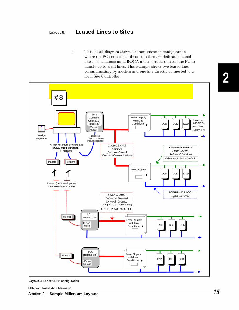
Layout 8: — Leased Lines to Sites
( ) This block diagram shows a communication configuration where the PC connects to three sites through dedicated leased-lines. installations use a BOCA multi-port card inside the PC to handle up to eight lines. This example shows two leased lines communicating by modem and one line directly connected to a local Site Controller.
PC with Millenium software and BOCA multi-port card.
(8 outputs)
Power Supply with Line
Conditioner DCD DCD DCD Power to 5-30 DCDs per power supply. ( *)
Power Supply DCD DCD DCD
Power Supply with Line
Conditioner RCD DCD DCD
2 pair-22 AWG Shielded
(One pair–Ground, One pair–Communications)
SITE Controller Unit (SCU)(local site)
SCU (remote site)
SCU (remote site)
POWER—13.8 VDC 1 pair-12 AWG
COMMUNICATIONS 1 pair-22 AWG
Twisted & Shielded Cable length limit = 5,000 ft.
Power Supply with Line
Conditioner RCD DCD DCD J3-DB9, RS-232
J3-DB9, RS-232
Wedge Keyreader
Leased (dedicated) phone lines to each remote site.
Modem
Modem
Modem
Modem
J3-DB9, RS-232
#8
1 pair-22 AWG Twisted & Shielded (One pair–Ground,
One pair–Communications)
SINGLE POWER SOURCE
Boca line direct connection(requires adapter)
Layout 8: LEASED LINE configuration

Millennium Group, Inc.
Section 2— Sample Millenium Layouts 16
This Page Intentionally Left Blank
Millenium Installation Manual ©
Section 3—Electrical Specifications 1
Electrical Specifications This section includes electrical specifications for: • Door Control Devices (DCDs)
• Relay Control Devices (RCDs)
• Site Controller Units (SCUs)
• Power Supply Refer to Section 4—Wiring Requirements, for details on wire/cable requirements and limits, and for wiring diagrams. Refer to Section 5—Connections, for details on terminal connections.
Millennium Group, Inc.
Section 3—Electrical Specifications 2
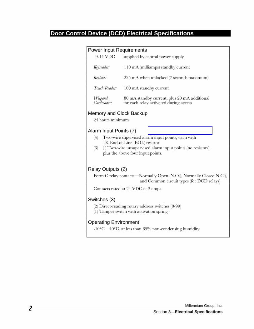
Door Control Device (DCD) Electrical Specifications Power Input Requirements 9-14 VDC supplied by central power supply Keyreader: 110 mA (milliamps) standby current Keyloks: 225 mA when unlocked (7 seconds maximum) Touch Reader: 100 mA standby current Wiegand 80 mA standby current, plus 20 mA additional Cardreader: for each relay activated during access Memory and Clock Backup 24 hours minimum Alarm Input Points (7) (4) Two-wire supervised alarm input points, each with 1K End-of-Line (EOL) resistor (3) ( ) Two-wire unsupervised alarm input points (no resistors), plus the above four input points. Relay Outputs (2) Form C relay contacts—Normally Open (N.O.), Normally Closed N.C.), and Common circuit types (for DCD relays)
Contacts rated at 24 VDC at 2 amps Switches (3) (2) Direct-reading rotary address switches (0-99) (1) Tamper switch with activation spring Operating Environment -10°C—40°C, at less than 85% non-condensing humidity
Millenium Installation Manual ©
Section 3—Electrical Specifications 3
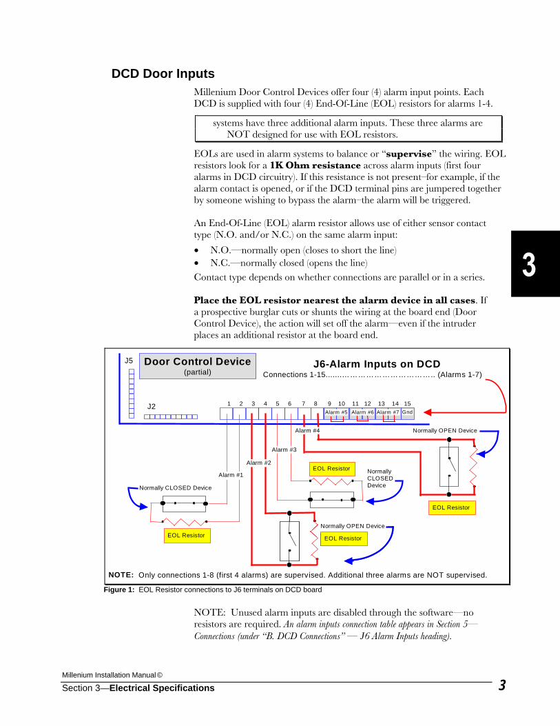
DCD Door Inputs Millenium Door Control Devices offer four (4) alarm input points. Each DCD is supplied with four (4) End-Of-Line (EOL) resistors for alarms 1-4.
systems have three additional alarm inputs. These three alarms are NOT designed for use with EOL resistors.
EOLs are used in alarm systems to balance or “supervise” the wiring. EOL resistors look for a 1K Ohm resistance across alarm inputs (first four alarms in DCD circuitry). If this resistance is not present–for example, if the alarm contact is opened, or if the DCD terminal pins are jumpered together by someone wishing to bypass the alarm–the alarm will be triggered. An End-Of-Line (EOL) alarm resistor allows use of either sensor contact type (N.O. and/or N.C.) on the same alarm input:
• N.O.—normally open (closes to short the line) • N.C.—normally closed (opens the line) Contact type depends on whether connections are parallel or in a series. Place the EOL resistor nearest the alarm device in all cases. If a prospective burglar cuts or shunts the wiring at the board end (Door Control Device), the action will set off the alarm—even if the intruder places an additional resistor at the board end.
NOTE: Unused alarm inputs are disabled through the software—no resistors are required. An alarm inputs connection table appears in Section 5—Connections (under “B. DCD Connections” — J6 Alarm Inputs heading).
Normally CLOSED Device
EOL Resistor Normally OPEN Device
EOL Resistor
EOL Resistor
1 2 3 4 5 6 7 8 9 10 11 12 13 14 15
Door Control Device(partial)
Alarm #1
Alarm #2
Alarm #3
Alarm #4
Normally CLOSED Device
NOTE: Only connections 1-8 (first 4 alarms) are supervised. Additional three alarms are NOT supervised.
J2
J5
Normally OPEN Device
EOL Resistor
Normally OPEN Device
EOL Resistor
J6-Alarm Inputs on DCD Connections 1-15.......…………………………….. (Alarms 1-7)
Alarm #5 Alarm #6 Alarm #7 Gnd
Figure 1: EOL Resistor connections to J6 terminals on DCD board
Millennium Group, Inc.
Section 3—Electrical Specifications 4
DCD Input Shunting The DCD allows you to shunt (bridge or by-pass) alarm circuits. With proper Millenium software configuration, the shunt relay of the DCD responds to both (1) a valid key/card for entry and, (2) the activation of the request to exit for egress (leaving).
(3) Variable shunt times are also available under software control. Based on the number of minutes set in the software, Alarm #7—the “door propped” alarm— controls how long a door opened by a valid user can remain ajar before an alarm event occurs.
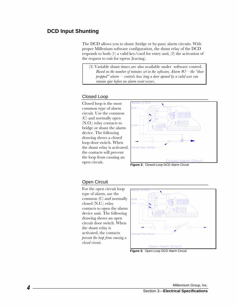
Closed Loop Closed loop is the most common type of alarm circuit. Use the common (C) and normally open (N.O.) relay contacts to bridge or shunt the alarm device. The following drawing shows a closed loop door switch. When the shunt relay is activated, the contacts will prevent the loop from causing an open circuit. Open Circuit For the open circuit loop type of alarm, use the common (C) and normally closed (N.C.) relay contacts to open the alarm device unit. The following drawing shows an open circuit door switch. When the shunt relay is activated, the contacts prevent the loop from causing a closed circuit.
Figure 2: Closed-Loop DCD Alarm Circuit
Figure 3: Open-Loop DCD Alarm Circuit
Millenium Installation Manual ©
Section 3—Electrical Specifications 5
DCD Request-to-Exit (R.E.X.)
Attention! Check local fire codes before installing any restrictions to the normal exit of a building or building space.
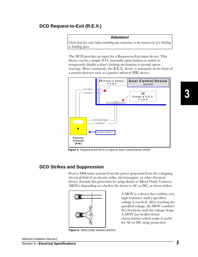
The DCD provides an input for a Request-to-Exit input device. This device can be a simple N.O. (normally open) button or switch to temporarily disable a door’s locking mechanism to permit egress (leaving). More commonly, the R.E.X. device is automatic in the form of a motion detector such as a passive infrared (PIR) device.
DCD Strikes and Suppression Protect Millenium systems from the power generated from the collapsing electrical field of an electric strike, electromagnet, or other electrical device. Furnish this protection by using diodes or Metal Oxide Varistors (MOVs) depending on whether the device is AC or DC, as shown below.
A MOV is a device that exhibits very high resistance until a specified voltage is reached. After reaching the specified voltage, the MOV conducts the electricity until the voltage drops. A MOV has bi-directional characteristics which make it useful for AC or DC surge protection.
J2R eader & R .E .X.
# 5 & 6
P assiveIn frared
(P IR )
N orm ally O pen
C om m on
13.8 V D C
G round
D oor C ontro l D evice(partia l)
M otion D etec tor
J5 -P ower & R elays# 2 & 4
Figure 4: Request-to-Exit (R.E.X.) input on Door Control Device (DCD)
Figure 5: Metal Oxide Varistors (MOVs)
Millennium Group, Inc.
Section 3—Electrical Specifications 6
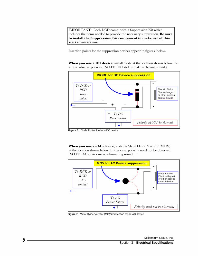
IMPORTANT: Each DCD comes with a Suppression Kit which includes the items needed to provide the necessary suppression. Be sure to install the Suppression Kit component to make use of this strike protection. Insertion points for the suppression devices appear in figures, below. When you use a DC device, install diode at the location shown below. Be sure to observe polarity. (NOTE: DC strikes make a clicking sound.)
When you use an AC device, install a Metal Oxide Varistor (MOV) at the location shown below. In this case, polarity need not be observed. (NOTE: AC strikes make a humming sound.)
DIODE for DC Device suppression
To DCD orRCDrelay
contact
Electric StrikeElectro-Magnet,or other accesscontrol device
Polarity MUST be observed.
++
–
To DCPower Source
+
Figure 6: Diode Protection for a DC device
MOV for AC Device suppression
To ACPower Source
To DCD orRCDrelay
contact
Electric StrikeElectro-Magnet,or other accesscontrol device
Polarity need not be observed.
Figure 7: Metal Oxide Varistor (MOV) Protection for an AC device
Millenium Installation Manual ©
Section 3—Electrical Specifications 7
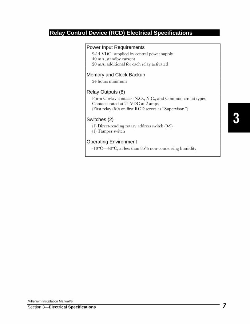
Relay Control Device (RCD) Electrical Specifications Power Input Requirements 9-14 VDC, supplied by central power supply 40 mA, standby current 20 mA, additional for each relay activated Memory and Clock Backup 24 hours minimum Relay Outputs (8) Form C relay contacts (N.O., N.C., and Common circuit types) Contacts rated at 24 VDC at 2 amps (First relay (#0) on first RCD serves as “Supervisor.”) Switches (2) (1) Direct-reading rotary address switch (0-9) (1) Tamper switch Operating Environment -10°C—40°C, at less than 85% non-condensing humidity
Millennium Group, Inc.
Section 3—Electrical Specifications 8
Site Controller Unit (SCU) Electrical Specifications
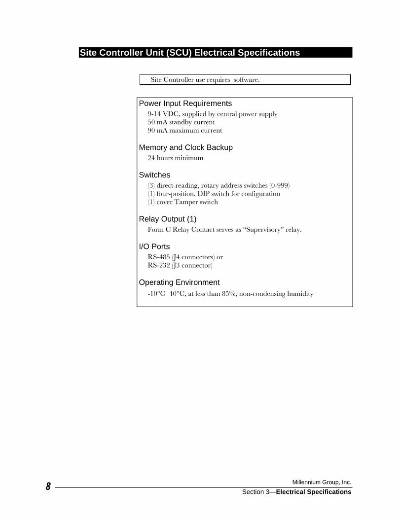
Site Controller use requires software.
Power Input Requirements 9-14 VDC, supplied by central power supply 50 mA standby current 90 mA maximum current Memory and Clock Backup 24 hours minimum Switches (3) direct-reading, rotary address switches (0-999) (1) four-position, DIP switch for configuration (1) cover Tamper switch Relay Output (1) Form C Relay Contact serves as “Supervisory” relay. I/O Ports RS-485 (J4 connectors) or RS-232 (J3 connector) Operating Environment -10°C−40°C, at less than 85%, non-condensing humidity
Millenium Installation Manual ©
Section 3—Electrical Specifications 9
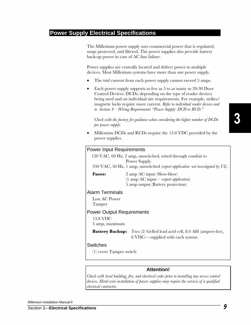
Power Supply Electrical Specifications The Millenium power supply uses commercial power that is regulated, surge protected, and filtered. The power supplies also provide battery back-up power in case of AC line failure. Power supplies are centrally located and deliver power to multiple devices. Most Millenium systems have more than one power supply.
• The total current from each power supply cannot exceed 5 amps.
• Each power supply supports as few as 5 to as many as 20-30 Door Control Devices (DCDs) depending on the type of reader devices being used and on individual site requirements. For example, strikes/ magnetic locks require more current. Refer to individual reader devices and to Section 4—Wiring Requirements “Power Supply–DCD or RCD.”
Check with the factory for guidance when considering the higher number of DCDs
per power supply.
• Millenium DCDs and RCDs require the 13.8 VDC provided by the power supplies.
Power Input Requirements 120 VAC, 60 Hz, 2 amp, unswitched, wired through conduit to
Power Supply 240 VAC, 50 Hz, 1 amp, unswitched (export application–not investigated by UL)
Fuses: 2 amp AC input (Slow-blow) (1 amp AC input —export application) 5 amp output (Battery protection)
Alarm Terminals Lost AC Power Tamper
Power Output Requirements 13.8 VDC 5 amp, maximum
Battery Backup: Two (2) Gelled lead acid cell, 8.0 AH (ampere-hrs), 6 VDC⎯ supplied with each system.
Switches (1) cover Tamper switch
Attention! Check with local building, fire, and electrical codes prior to installing any access control devices. Hard-wire installation of power supplies may require the services of a qualified electrical contractor.
Millennium Group, Inc.
Section 3—Electrical Specifications 10
Power Supply Location Place each power supply in the system as close as possible to the devices it will be powering. The temperature in the chosen location should not be extreme. The supply will need a source of unswitched AC power that comes from a junction box. The source of the AC power should be protected against short-circuits or over-current by means of a circuit-breaker or the like. Do not use a cord and wall outlet. The power supply should be securely screwed to the wall using the four mounting holes. If possible, the power supply should be mounted at a workable height with clearance to open the door completely.
Power Supply Wire/Cable Sizes & Limits Follow the wire/cable requirements outlined in Section 4—Wiring Requirements & Diagrams. To determine the proper wire size for each individual wire run from a power supply, use the wire size selection charts under B. “How to Select Wire Sizes” in Section 4—Wiring Requirements.
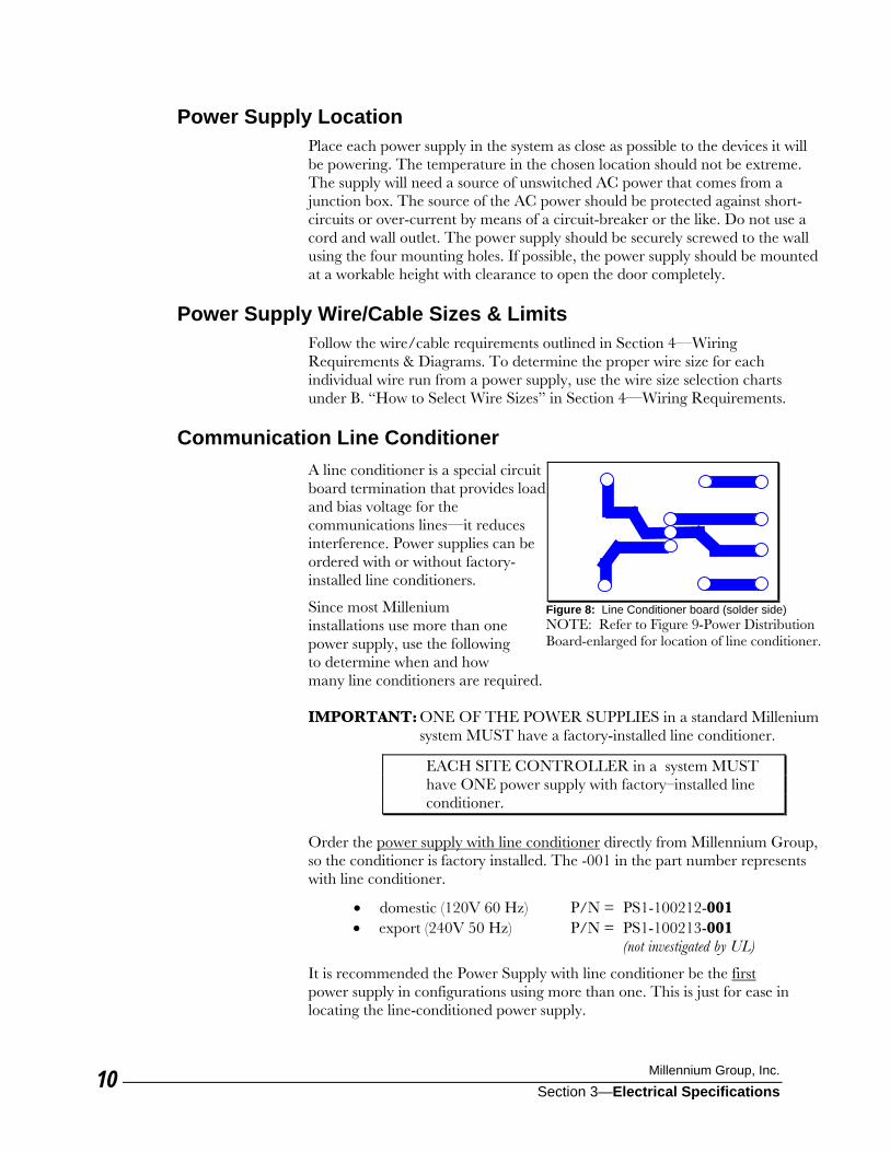
Communication Line Conditioner A line conditioner is a special circuit board termination that provides load and bias voltage for the communications lines—it reduces interference. Power supplies can be ordered with or without factory-installed line conditioners.
Since most Millenium installations use more than one power supply, use the following to determine when and how many line conditioners are required. IMPORTANT: ONE OF THE POWER SUPPLIES in a standard Millenium
system MUST have a factory-installed line conditioner.
EACH SITE CONTROLLER in a system MUST have ONE power supply with factory–installed line conditioner.
Order the power supply with line conditioner directly from Millennium Group, so the conditioner is factory installed. The -001 in the part number represents with line conditioner.
• domestic (120V 60 Hz) P/N = PS1-100212-001 • export (240V 50 Hz) P/N = PS1-100213-001
(not investigated by UL)
It is recommended the Power Supply with line conditioner be the first power supply in configurations using more than one. This is just for ease in locating the line-conditioned power supply.
Figure 8: Line Conditioner board (solder side) NOTE: Refer to Figure 9-Power Distribution Board-enlarged for location of line conditioner.

Millenium Installation Manual ©
Section 3—Electrical Specifications 11
Earth Ground
Power Supply Alarms (Lost AC Power & Tamper) The Millenium power supply provides terminals for both of the following alarm conditions:
• Loss of AC line power
• Tampering: A door-mounted tamper switch indicates when the door is ajar or opened.
Contacts for the above conditions are normally closed, and may be connected to a nearby DCD for monitoring these alarm functions. Refer to Section 5—Connections: B. DCD Connections—the J6 Alarm Inputs termination table. DCD Alarm Inputs are also discussed under Door Control Device Electrical Specifications, at the beginning of this section.
Grounding To further suppress interference by electrical devices such as electric strikes, all installations must be properly grounded. Proper grounding means:
• Attach first Power Supply terminal No. 12 to an earth ground. Earth ground is represented in wiring drawings as :
• Do not use conduit or shielding as your ground source.
A drawing on the following page shows the Power Supply with distribution board enlarged. Notice that three ground-type terminal connections exist on the Power Supply distribution board. Terminal #2-GND is the AC Ground connection. Terminal #4-DCD is the DC COMMON ground for power and signal. Terminal #12-GND is for both the shield connection from communications wiring and for the earth ground from the first Power Supply in a configuration.
Lightning Protection Underground or overhead wiring outside the facility building requires protection from lightning and stray electro-magnetic fields (EMFs). The protective device you choose must meet the requirements of your communication network (4-wire RS-485 or RS-232 standards).
Install protection devices at all locations where data cables enter or exit the building. Follow the manufacturer’s instructions to properly install and ground the protection devices.
Battery Replacement WARNING: The power supply uses high voltage. Only a qualified person should replace the back-up batteries.
Prior to replacing the back-up batteries, mark down the color and location of each wire and the orientation of both batteries. Disconnect all wires. While holding the retaining bracket and batteries in place, remove both screws. Replace both batteries with the same type of gelled lead acid cell 8.0 AH (ampere-hours) 6 VDC (volts DC.) Place the new batteries in the same position as the original batteries. Reinstall the retaining bracket, and reconnect all wires according to the color and location you recorded. Dispose of the old batteries in accordance with your local regulations.
Millennium Group, Inc.
Section 3—Electrical Specifications 12
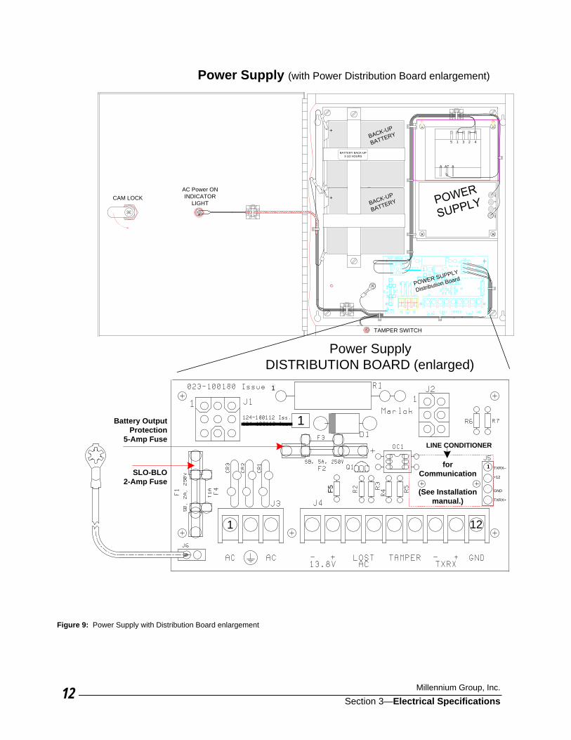
Power Supply (with Power Distribution Board enlargement)
RDI
1
2 45 1 3
ATA A
+OU
T+S
-S-O
UT
POWER SUPPLY
Distribution Board
+
+BACK-UP
BATTERY
BACK-UP
BATTERY
TAMPER SWITCH
CAM LOCKAC Power ONINDICATOR
LIGHT
1
BATTERY BACK-UP3-1/2 HOURS
1Battery OutputProtection
5-Amp Fuse
SLO-BLO2-Amp Fuse
LINE CONDITIONER
TXRX–
+12
GND
TXRX+
1forCommunication
(See Installationmanual.)
1
1 12
F5
Power SupplyDISTRIBUTION BOARD (enlarged)
Figure 9: Power Supply with Distribution Board enlargement
Millenium Installation Manual ©
Section 4—Wiring Requirements & Diagrams 1
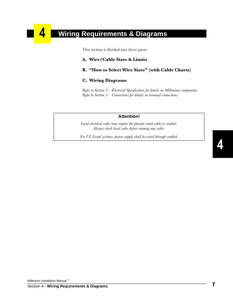
Wiring Requirements & Diagrams This section is divided into three parts: A. Wire/Cable Sizes & Limits B. “How to Select Wire Sizes” (with Cable Charts) C. Wiring Diagrams Refer to Section 3—Electrical Specification for details on Millenium components. Refer to Section 5—Connections for details on terminal connections.
Attention! Local electrical codes may require the plenum-rated cable or conduit.
Always check local codes before running any cable.
For UL Listed systems, power supply shall be wired through conduit.
Millennium Group, Inc.
Section 4—Wiring Requirements & Diagrams2
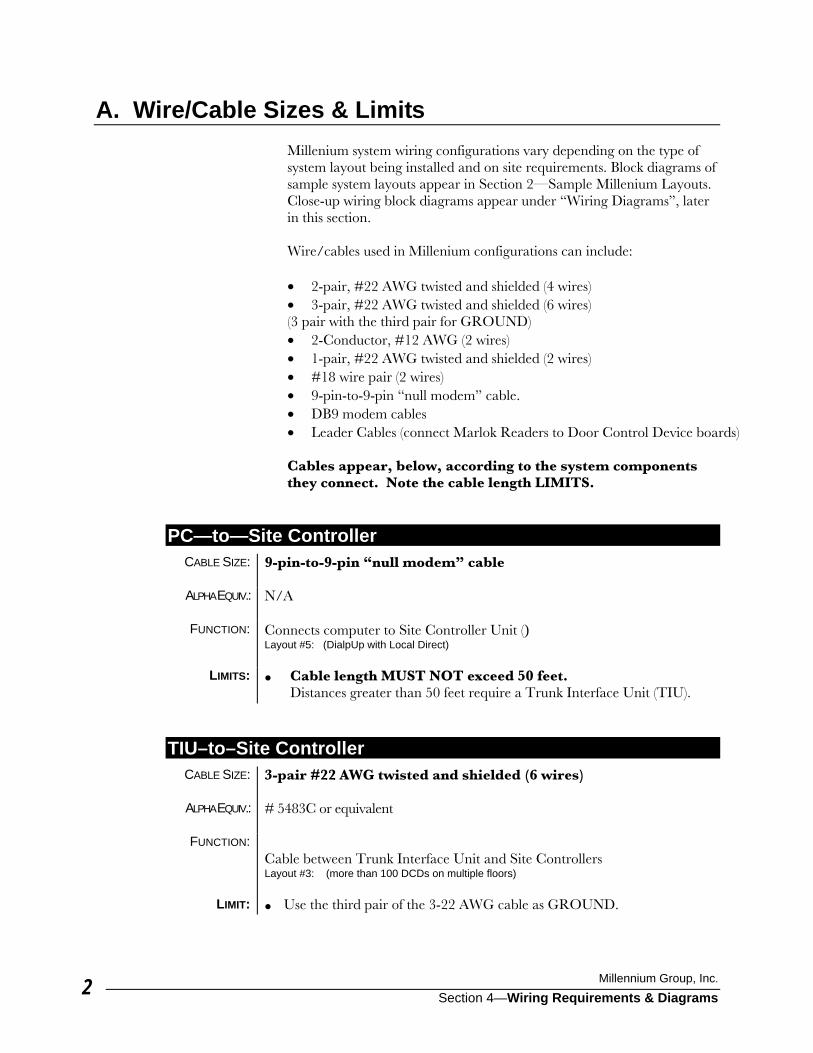
A. Wire/Cable Sizes & Limits Millenium system wiring configurations vary depending on the type of system layout being installed and on site requirements. Block diagrams of sample system layouts appear in Section 2—Sample Millenium Layouts. Close-up wiring block diagrams appear under “Wiring Diagrams”, later in this section. Wire/cables used in Millenium configurations can include: • 2-pair, #22 AWG twisted and shielded (4 wires) • 3-pair, #22 AWG twisted and shielded (6 wires) (3 pair with the third pair for GROUND) • 2-Conductor, #12 AWG (2 wires) • 1-pair, #22 AWG twisted and shielded (2 wires) • #18 wire pair (2 wires) • 9-pin-to-9-pin “null modem” cable. • DB9 modem cables • Leader Cables (connect Marlok Readers to Door Control Device boards)
Cables appear, below, according to the system components they connect. Note the cable length LIMITS.
PC—to—Site Controller CABLE SIZE: 9-pin-to-9-pin “null modem” cable
ALPHA EQUIV.: N/A
FUNCTION: Connects computer to Site Controller Unit ()
Layout #5: (DialpUp with Local Direct)
LIMITS: • Cable length MUST NOT exceed 50 feet. Distances greater than 50 feet require a Trunk Interface Unit (TIU).
TIU–to–Site Controller CABLE SIZE: 3-pair #22 AWG twisted and shielded (6 wires)
ALPHA EQUIV.: # 5483C or equivalent
FUNCTION:
Cable between Trunk Interface Unit and Site Controllers Layout #3: (more than 100 DCDs on multiple floors)
LIMIT: • Use the third pair of the 3-22 AWG cable as GROUND.

Millenium Installation Manual ©
Section 4—Wiring Requirements & Diagrams 3
Power Supply—to—Power Supply Power Supply—to—Trunk Interface Unit (TIU) Power Supply— to—Site Controller
CABLE SIZE: 2-pair #22 AWG twisted and shielded (4 wires) NOTE: If a single power supply is used, wiring can be 1-pair (2-conductor) 22 AWG twisted.
ALPHA EQUIV.: # 5482C or equivalent
FUNCTION: Primary link between the PC and the Millenium access control network. Cable between TIU and Power Supply and between Power Supplies Layout #1 (single site with 100 or less DCDs) Cable between Power Supply and Site Controllers, and between multiple Power Supplies. Layouts #2-8 Single Power Supply configurations appear as part of Layouts #5-8.
LIMITS: • 5,000 feet maximum length per system ( Example: five 1,000-foot runs)
• 5,000 feet maximum length per Site Controller (Example: five 1,000-foot runs per Site Controller.)
Millennium Group, Inc.
Section 4—Wiring Requirements & Diagrams4
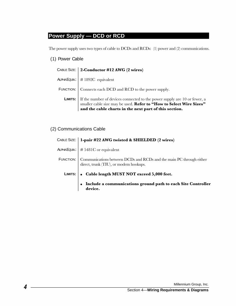
Power Supply — DCD or RCD The power supply uses two types of cable to DCDs and RCDs: (1) power and (2) communications. (1) Power Cable
CABLE SIZE: 2-Conductor #12 AWG (2 wires)
ALPHA EQUIV.: # 1892C equivalent
FUNCTION: Connects each DCD and RCD to the power supply.
LIMITS: If the number of devices connected to the power supply are 10 or fewer, a
smaller cable size may be used. Refer to “How to Select Wire Sizes” and the cable charts in the next part of this section.
(2) Communications Cable
CABLE SIZE: 1-pair #22 AWG twisted & SHIELDED (2 wires)
ALPHA EQUIV.: # 5481C or equivalent
FUNCTION: Communications between DCDs and RCDs and the main PC through either
direct, trunk (TIU), or modem hookups.
LIMITS: • Cable length MUST NOT exceed 5,000 feet.
• Include a communications ground path to each Site Controller device.
Millenium Installation Manual ©
Section 4—Wiring Requirements & Diagrams 5
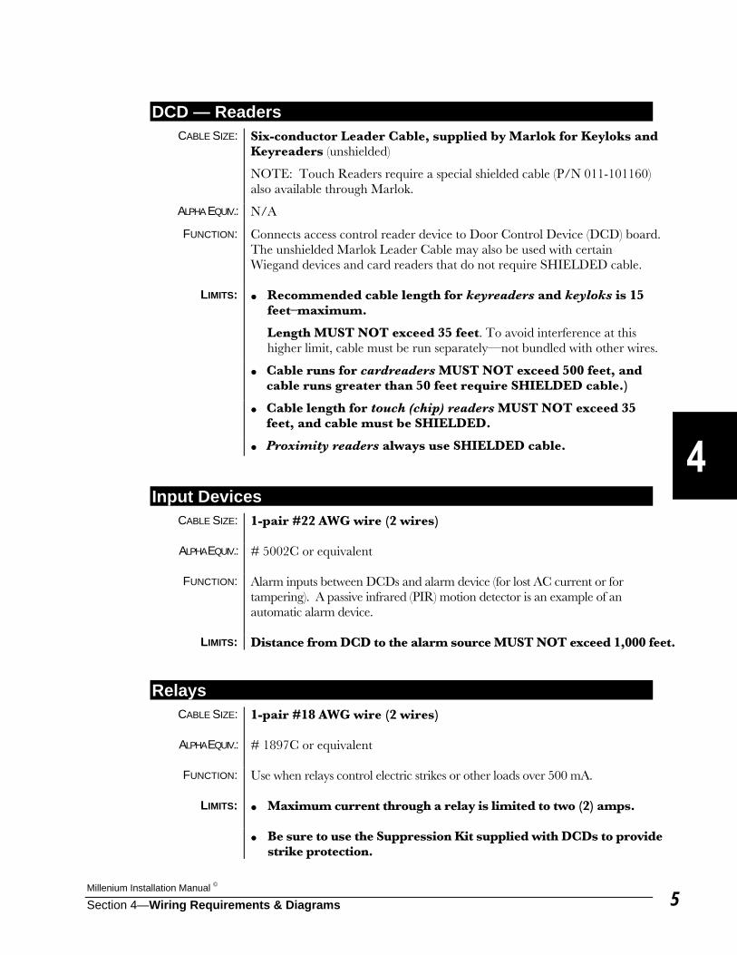
DCD — Readers CABLE SIZE: Six-conductor Leader Cable, supplied by Marlok for Keyloks and
Keyreaders (unshielded)
NOTE: Touch Readers require a special shielded cable (P/N 011-101160) also available through Marlok.
ALPHA EQUIV.: N/A
FUNCTION: Connects access control reader device to Door Control Device (DCD) board. The unshielded Marlok Leader Cable may also be used with certain Wiegand devices and card readers that do not require SHIELDED cable.
LIMITS: • Recommended cable length for keyreaders and keyloks is 15 feet–maximum.
Length MUST NOT exceed 35 feet. To avoid interference at this higher limit, cable must be run separately—not bundled with other wires.
• Cable runs for cardreaders MUST NOT exceed 500 feet, and cable runs greater than 50 feet require SHIELDED cable.)
• Cable length for touch (chip) readers MUST NOT exceed 35 feet, and cable must be SHIELDED.
• Proximity readers always use SHIELDED cable.
Input Devices CABLE SIZE: 1-pair #22 AWG wire (2 wires)
ALPHA EQUIV.: # 5002C or equivalent
FUNCTION: Alarm inputs between DCDs and alarm device (for lost AC current or for
tampering). A passive infrared (PIR) motion detector is an example of an automatic alarm device.
LIMITS: Distance from DCD to the alarm source MUST NOT exceed 1,000 feet.
Relays CABLE SIZE: 1-pair #18 AWG wire (2 wires)
ALPHA EQUIV.: # 1897C or equivalent
FUNCTION: Use when relays control electric strikes or other loads over 500 mA.
LIMITS: • Maximum current through a relay is limited to two (2) amps.
• Be sure to use the Suppression Kit supplied with DCDs to provide
strike protection.

Millenium Installation Manual ©
Section 4—Wiring Requirements & Diagrams 7
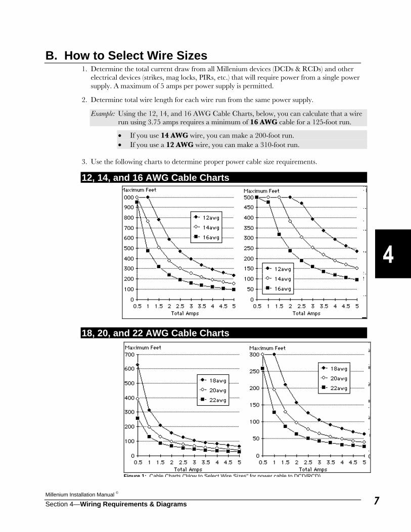
B. How to Select Wire Sizes 1. Determine the total current draw from all Millenium devices (DCDs & RCDs) and other
electrical devices (strikes, mag locks, PIRs, etc.) that will require power from a single power supply. A maximum of 5 amps per power supply is permitted.
2. Determine total wire length for each wire run from the same power supply.
Example: Using the 12, 14, and 16 AWG Cable Charts, below, you can calculate that a wire run using 3.75 amps requires a minimum of 16 AWG cable for a 125-foot run.
• If you use 14 AWG wire, you can make a 200-foot run. • If you use a 12 AWG wire, you can make a 310-foot run.
3. Use the following charts to determine proper power cable size requirements.
12, 14, and 16 AWG Cable Charts
18, 20, and 22 AWG Cable Charts
Figure 1: Cable Charts ("How to Select Wire Sizes" for power cable to DCD/RCD)

Millennium Group, Inc.
Section 4—Wiring Requirements & Diagrams8
C. Wiring Diagrams This section contains the following wiring diagrams: • DCD–to–DCD
• DCD to Readers
• Power Supply–to–Power Supply
• Site Controller and Modem
• Site Controller and TIU Wiring diagrams on the upcoming pages are packed with information, but can be overwhelming at first glance. Be assured that labels are screen-printed on most Millenium circuit boards. These labels will serve as a wiring reference for terminal connections. Adhesive labels are also provided with circuit boards as a wiring reference. Wiring terminal blocks are identified by a “letter—number” combination, such as “J3” for Communications on the DCD board. Once you’ve found the terminal block, notice that most terminals in the block are also labeled with their function. For example, terminals #1 and 2 on the DCD J3 block shows “+TXR–”, meaning the terminal connections for transmitting and receiving communications data. Verify connections using the labels printed on circuit boards when wiring to be sure of proper connections. Refer to Section 5—Connections, as needed, for all terminal connection blocks and their terminal numbers.
Millenium Installation Manual ©
Section 4—Wiring Requirements & Diagrams 9
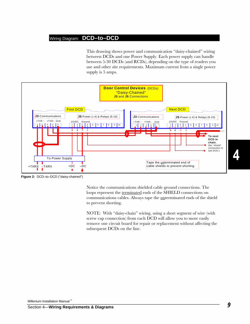
Wiring Diagram: DCD–to–DCD This drawing shows power and communication “daisy-chained” wiring between DCDs and one Power Supply. Each power supply can handle between 5-30 DCDs (and RCDs), depending on the type of readers you use and other site requirements. Maximum current from a single power supply is 5 amps.
Notice the communications shielded cable ground connections. The loops represent the terminated ends of the SHIELD connections on communications cables. Always tape the unterminated ends of the shield to prevent shorting. NOTE: With “daisy-chain” wiring, using a short segment of wire (with screw cap connection) from each DCD will allow you to more easily remove one circuit board for repair or replacement without affecting the subsequent DCDs on the line.
...
+TXR – +TXR– Gnd
Door Control Devices (DCDs)“Daisy-Chained”
J3 and J5 Connections
J3-Communications J5-Power (1-4) & Relays (5-10)
1 2 3 4 5 6 7 8 9 10
J3-Communications J5-Power (1-4) & Relays (5-10)
+ + – –
1 2 3 4 5 13VDC Ground
First DCD Next DCD
1 2 3 4 5
+TXR – +TXR– Gnd
To nextDCD inchain.(No “shield”connection inlast DCD.)
1 2 3 4 5 6 7 8 9 10
13VDC Ground
+ + – –
To Power Supply
+DC –DCTape the unterminated end ofcable shields to prevent shorting.+TXRX –TXRX
Figure 2: DCD–to–DCD ("daisy-chained")
Millennium Group, Inc.
Section 4—Wiring Requirements & Diagrams10
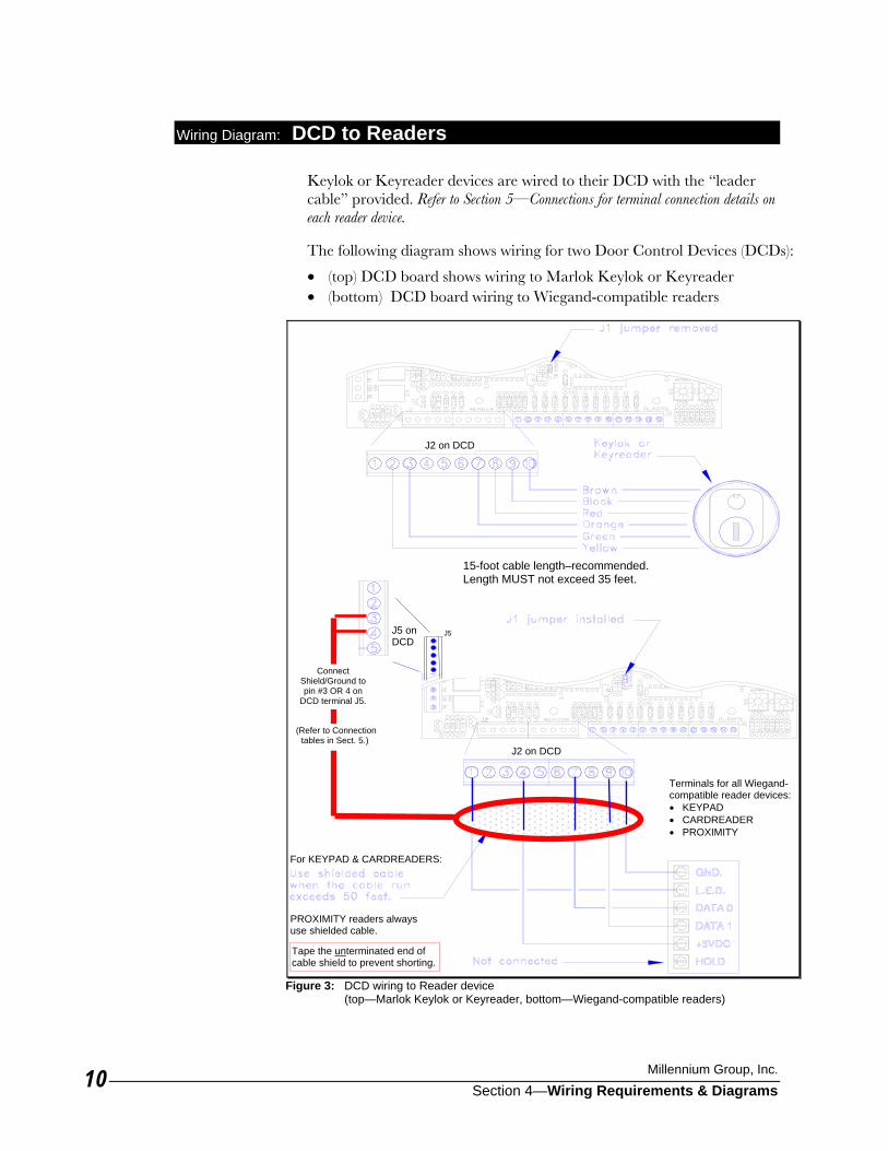
Wiring Diagram: DCD to Readers Keylok or Keyreader devices are wired to their DCD with the “leader cable” provided. Refer to Section 5—Connections for terminal connection details on each reader device. The following diagram shows wiring for two Door Control Devices (DCDs):
• (top) DCD board shows wiring to Marlok Keylok or Keyreader • (bottom) DCD board wiring to Wiegand-compatible readers
Figure 3: DCD wiring to Reader device (top—Marlok Keylok or Keyreader, bottom—Wiegand-compatible readers)
Terminals for all Wiegand-compatible reader devices: • KEYPAD • CARDREADER • PROXIMITY
J5
J2 on DCD
J5 on DCD
Tape the unterminated end of cable shield to prevent shorting.
J2 on DCD
For KEYPAD & CARDREADERS:
PROXIMITY readers always use shielded cable.
15-foot cable length–recommended. Length MUST not exceed 35 feet.
Connect Shield/Ground to pin #3 OR 4 on
DCD terminal J5.
(Refer to Connection tables in Sect. 5.)
Millenium Installation Manual ©
Section 4—Wiring Requirements & Diagrams 11
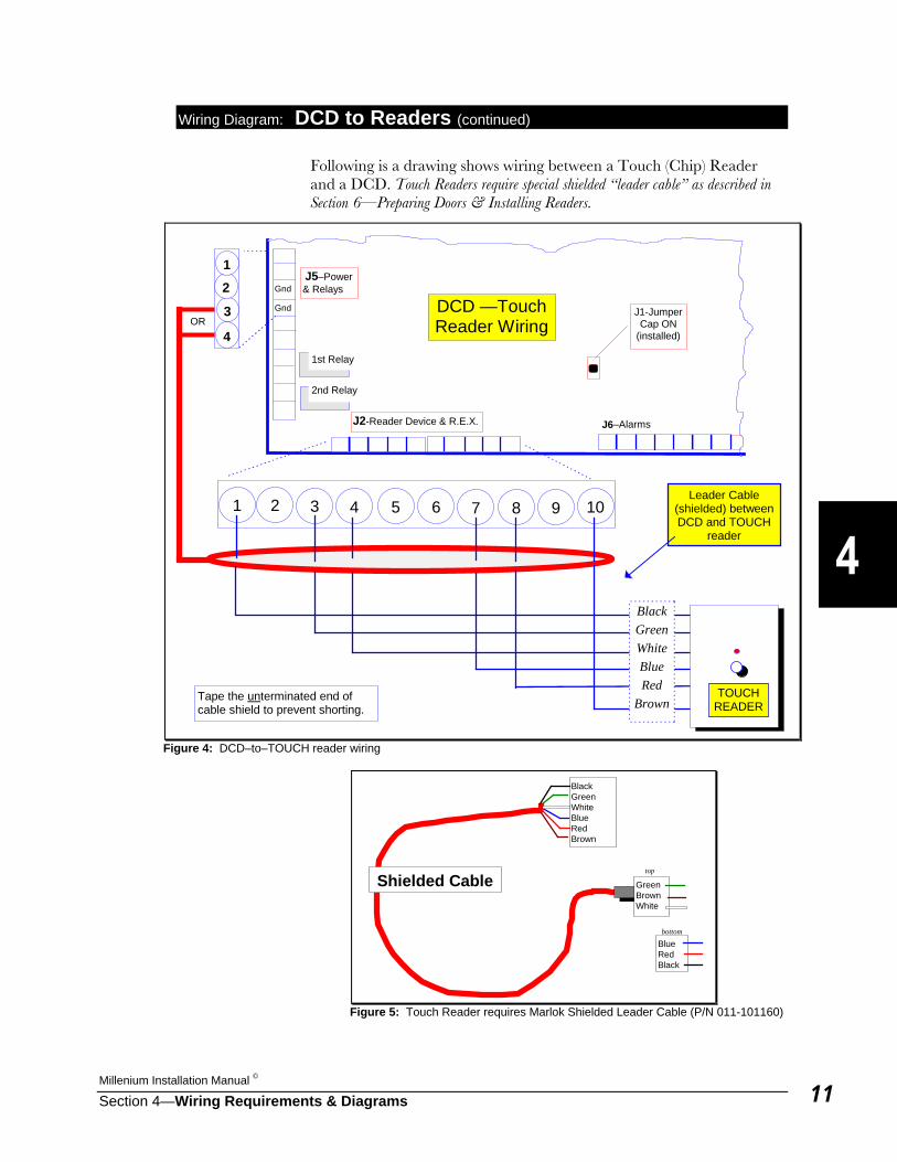
Wiring Diagram: DCD to Readers (continued) Following is a drawing shows wiring between a Touch (Chip) Reader and a DCD. Touch Readers require special shielded “leader cable” as described in Section 6—Preparing Doors & Installing Readers.
J2-Reader Device & R.E.X. J6–Alarms
DCD —TouchReader Wiring
1 2 3 654 8 9 107
TOUCHREADER
BlackGreenWhiteBlueRed
Brown
Leader Cable(shielded) betweenDCD and TOUCH
reader
J5–Power& Relays
J1-JumperCap ON
(installed)
Tape the unterminated end ofcable shield to prevent shorting.
Gnd
Gnd3
2
4
1
1st Relay
2nd Relay
OR
Figure 4: DCD–to–TOUCH reader wiring
BlackGreenWhiteBlueRedBrown
GreenBrownWhite
top
BlueRedBlack
bottom
Shielded Cable
Figure 5: Touch Reader requires Marlok Shielded Leader Cable (P/N 011-101160)
Millennium Group, Inc.
Section 4—Wiring Requirements & Diagrams12
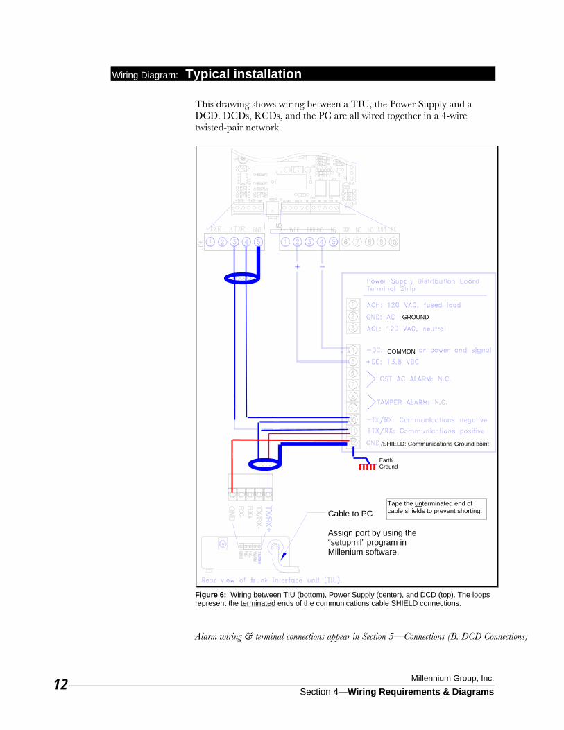
Wiring Diagram: Typical installation This drawing shows wiring between a TIU, the Power Supply and a DCD. DCDs, RCDs, and the PC are all wired together in a 4-wire twisted-pair network.
Figure 6: Wiring between TIU (bottom), Power Supply (center), and DCD (top). The loops represent the terminated ends of the communications cable SHIELD connections. Alarm wiring & terminal connections appear in Section 5—Connections (B. DCD Connections)
Cable to PC Assign port by using the “setupmil” program in Millenium software.
Tape the unterminated end of cable shields to prevent shorting.
/SHIELD: Communications Ground point
COMMON
GROUND
Earth Ground
Millenium Installation Manual ©
Section 4—Wiring Requirements & Diagrams 13
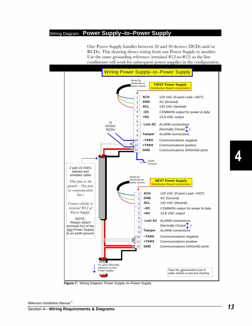
Wiring Diagram: Power Supply–to–Power Supply One Power Supply handles between 20 and 30 devices (DCDs and/or RCDs). This drawing shows wiring from one Power Supply to another. Use the same grounding reference (terminal #12-to-#12) so the line conditioner will work for subsequent power supplies in the configuration.
Wiring Power Supply–to–Power Supply
ACH 120 VAC (Fused Load—HOT)GND AC (Ground)ACL 120 VAC (Neutral)
–DC COMMON output for power & data+DC 13.8 VDC output
Lost AC ALARM connections(Normally Closed )
Tamper ALARM connections
–TXRX Communications negative+TXRX Communications positiveGND Communications GROUND point
FIRST Power SupplyDistribution Board connections
ACH 120 VAC (Fused Load—HOT)GND AC (Ground)ACL 120 VAC (Neutral)
–DC COMMON output for power & data+DC 13.8 VDC output
Lost AC ALARM connections(Normally Closed )
Tamper ALARM connections
–TXRX Communications negative+TXRX Communications positiveGND Communications GROUND point
NEXT Power SupplyDistribution Board connections
1
2
3
4
5
6
7
8
9
10
11
12
Wired byelectrician topower source.
To same GROUNDreference at nextPower Supply
1
2
3
4
5
6
7
8
9
10
11
12
Wired byelectrician topower source.
2 pair-22 AWGtwisted and
shielded cable
(One pair as theground – One pairas communication
line.)
Connect shields toterminal #12 ofPower Supply.
NOTE:Always attach
terminal #12 of thefirst Power Supplyto an earth ground.
toDCDs/RCDs
Tape the unterminated end ofcable shields to prevent shorting.
EarthGround
Figure 7: Wiring Diagram: Power Supply–to–Power Supply
Millennium Group, Inc.
Section 4—Wiring Requirements & Diagrams14
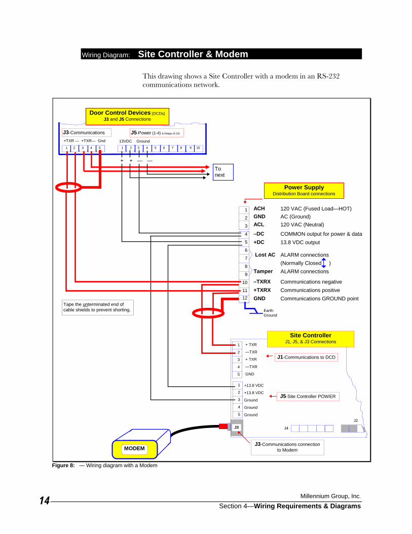
Wiring Diagram: Site Controller & Modem This drawing shows a Site Controller with a modem in an RS-232 communications network.
J3-Communications J5-Power (1-4) & Relays (5-10)
ACH 120 VAC (Fused Load—HOT)GND AC (Ground)ACL 120 VAC (Neutral)
–DC COMMON output for power & data+DC 13.8 VDC output
Lost AC ALARM connections(Normally Closed )
Tamper ALARM connections
–TXRX Communications negative+TXRX Communications positiveGND Communications GROUND point
Power SupplyDistribution Board connections
1
2
3
4
5
1
2
3
4
5
J3
J1-Communications to DCD
J5-Site Controller POWER
+ TXR
—TXR
+ TXR
—TXR
GND
+13.8 VDC
+13.8 VDC
Ground
Ground
Ground
1
2
3
4
5
6
7
8
9
10
1112
J3-Communications connectionto Modem
J4
J2
+TXR — +TXR— Gnd
1 2 3 4 5 6 7 8 9 10 1 2 3 4 5
13VDC Ground
+ + — —
Door Control Devices (DCDs)J3 and J5 Connections
Tonext
Tape the unterminated end ofcable shields to prevent shorting.
Site ControllerJ1, J5, & J3 Connections
MODEM
EarthGround
Figure 8: — Wiring diagram with a Modem
Millenium Installation Manual ©
Section 4—Wiring Requirements & Diagrams 15
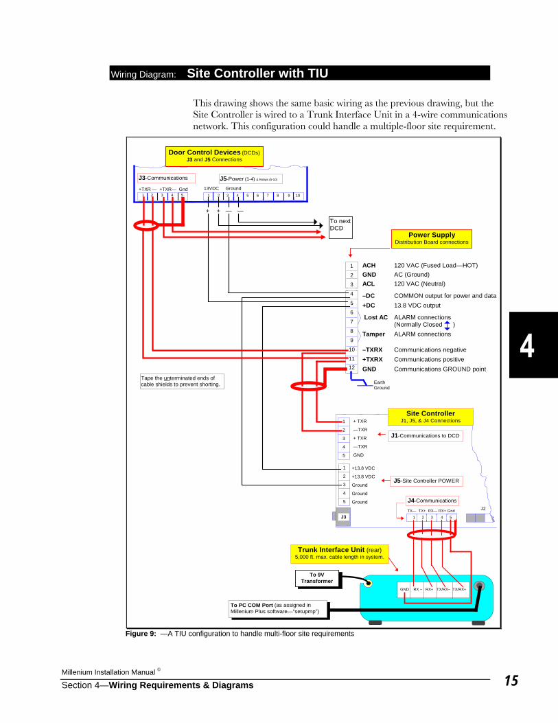
Wiring Diagram: Site Controller with TIU This drawing shows the same basic wiring as the previous drawing, but the Site Controller is wired to a Trunk Interface Unit in a 4-wire communications network. This configuration could handle a multiple-floor site requirement.
+TXR — +TXR— Gnd
J3-Communications J5-Power (1-4) & Relays (5-10)
ACH 120 VAC (Fused Load—HOT)GND AC (Ground)ACL 120 VAC (Neutral)
–DC COMMON output for power and data+DC 13.8 VDC output
Lost AC ALARM connections(Normally Closed )
Tamper ALARM connections
–TXRX Communications negative+TXRX Communications positiveGND Communications GROUND point
Power SupplyDistribution Board connections
1 2 3 4 5 6 7 8 9 10
1
2
3
4
5
1
2
3
4
5
J3
J1-Communications to DCD
J5-Site Controller POWER
+ TXR
—TXR
+ TXR
—TXR
GND
+13.8 VDC
+13.8 VDC
Ground
Ground
Ground
1
2
3
4
5
6
7
8
9
10
1112
+ + — —
J2
Trunk Interface Unit (rear)5,000 ft. max. cable length in system.
1 2 3 4 5
J4-Communications
TX— TX+ RX— RX+ Gnd
1 2 3 4 5
13VDC Ground
Door Control Devices (DCDs)J3 and J5 Connections
To nextDCD
To PC COM Port (as assigned inMillenium Plus software—“setupmp”)
GND RX – RX+ TX/RX– TX/RX+
Tape the unterminated ends ofcable shields to prevent shorting.
Site ControllerJ1, J5, & J4 Connections
EarthGround
To 9VTransformer
Figure 9: —A TIU configuration to handle multi-floor site requirements

Millennium Group, Inc.
Section 4—Wiring Requirements & Diagrams16
This Page Intentionally Left Blank
Millenium Installation Manual ©
Section 5— Connections 1
Connections This section contains details on how Millenium system components are connected to each other at wiring terminations. Information is divided as follows: A. Reader Device Connections B. Door Control Device (DCD) Connections C. Relay Control Device (RCD) Connections D. Trunk Interface Unit (TIU) Connections E. Site Controller Unit (SCU) Connections F. Shielded Cable Connections (Communications) Section 4—Wiring Requirement & Diagrams shows details on the wiring of system components. Section 6—Preparing Doors and Installing Readers gives step-by-step instructions on how to install Reader Devices in prepared doors.
A. Reader Device Connections
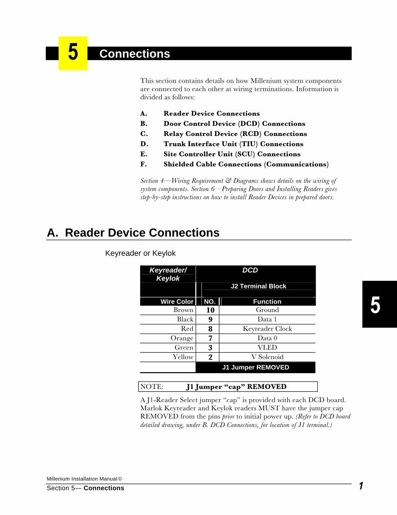
Keyreader or Keylok
Keyreader/ Keylok
DCD
J2 Terminal Block
Wire Color NO. Function Brown 10 Ground Black 9 Data 1
Red 8 Keyreader Clock Orange 7 Data 0
Green 3 VLED Yellow 2 V Solenoid
J1 Jumper REMOVED
NOTE: J1 Jumper “cap” REMOVED
A J1-Reader Select jumper “cap” is provided with each DCD board. Marlok Keyreader and Keylok readers MUST have the jumper cap REMOVED from the pins prior to initial power up. (Refer to DCD board detailed drawing, under B. DCD Connections, for location of J1 terminal.)
Millennium Group, Inc.
Section 5— Connections 2
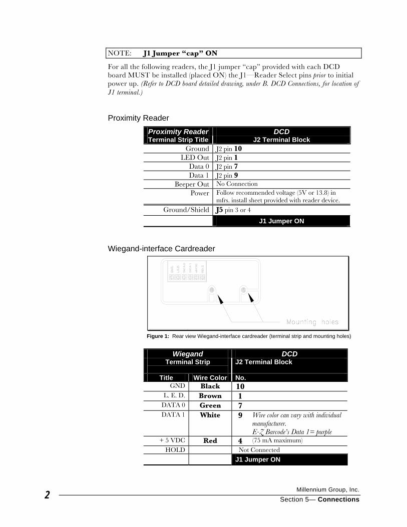
NOTE: J1 Jumper “cap” ON
For all the following readers, the J1 jumper “cap” provided with each DCD board MUST be installed (placed ON) the J1—Reader Select pins prior to initial power up. (Refer to DCD board detailed drawing, under B. DCD Connections, for location of J1 terminal.)
Proximity Reader
Proximity Reader DCD Terminal Strip Title J2 Terminal Block
Ground J2 pin 10 LED Out J2 pin 1
Data 0 J2 pin 7 Data 1 J2 pin 9
Beeper Out No Connection Power Follow recommended voltage (5V or 13.8) in
mfrs. install sheet provided with reader device.
Ground/Shield J5 pin 3 or 4
J1 Jumper ON
Wiegand-interface Cardreader
Wiegand DCD
Terminal Strip
J2 Terminal Block
Title Wire Color No. GND Black 10
L. E. D. Brown 1 DATA 0 Green 7 DATA 1 White 9 Wire color can vary with individual
manufacturer. E-Z Barcode’s Data 1= purple
+ 5 VDC Red 4 (75 mA maximum) HOLD Not Connected
J1 Jumper ON
Figure 1: Rear view Wiegand-interface cardreader (terminal strip and mounting holes)
Millenium Installation Manual ©
Section 5— Connections 3
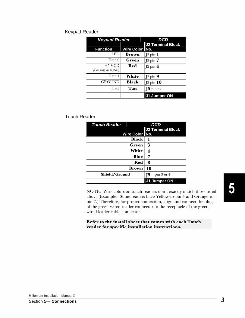
Keypad Reader Keypad Reader DCD
Function
Wire Color
J2 Terminal Block No.
LED Brown J2 pin 1 Data 0 Green J2 pin 7
+5 VCD(Can vary by keypad)
Red J2 pin 4
Data 1 White J2 pin 9 GROUND Black J2 pin 10
(Case Tan J5 pin 4)
J1 Jumper ON
Touch Reader Touch Reader DCD
Wire ColorJ2 Terminal Block No.
Black 1
Green 3
White 4
Blue 7
Red 8
Brown 10
Shield/Ground J5 pin 3 or 4
J1 Jumper ON NOTE: Wire colors on touch readers don’t exactly match those listed above (Example: Some readers have Yellow-to-pin 4 and Orange-to-pin 7.) Therefore, for proper connection, align and connect the plug of the green-wired reader connector to the receptacle of the green-wired leader cable connector. Refer to the install sheet that comes with each Touch reader for specific installation instructions.
Millennium Group, Inc.
Section 5— Connections 4
B. Door Control Device (DCD) Connections
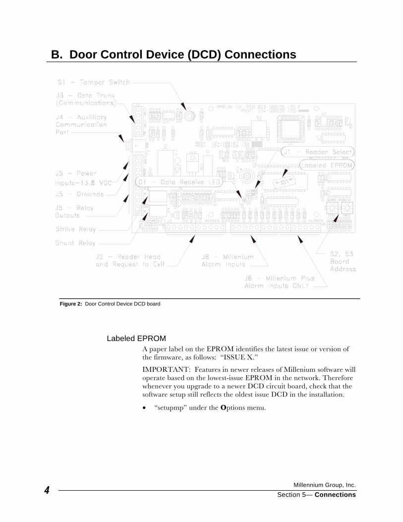
Labeled EPROM A paper label on the EPROM identifies the latest issue or version of the firmware, as follows: “ISSUE X.”
IMPORTANT: Features in newer releases of Millenium software will operate based on the lowest-issue EPROM in the network. Therefore whenever you upgrade to a newer DCD circuit board, check that the software setup still reflects the oldest issue DCD in the installation.
• “setupmp” under the Options menu.
Figure 2: Door Control Device DCD board
Millenium Installation Manual ©
Section 5— Connections 5
S2, S3 – Board Address (Address Select): The board address is a UNIQUE identifying number for Door Control Devices (DCDs). Millenium software uses the board address to identify the DCD Number for polling DCDs in sequence. Set the DCD board address using two direct-reading rotary dials. Board address range is 00-99. Use the dials as follows: S3 dial—10s-digit setting, S2 dial—1s-digit setting Example: If Board Address is 45, S3 dial = 4 and S2 dial = 5. In the software, the Door No. would be programmed as 45.
D1 – Data Receive LED You can tell the status of the DCD with the following indicators:
• OFF — the DCD receives no input power
• Blinking slowly — the DCD operates normally, but no communications are being received
• Blinking rapidly — communications are being received.
J1 – Reader Select (Type) —referred to as “Jumper Cap”
IMPORTANT: Install “Jumper Cap” BEFORE applying power.
• Set Jumper OFF to use Marlok Keyreader or Keylok (OFF = jumper “cap” is not installed on J1 terminal.)
• Set Jumper ON to use all readers except Marlok Keyreaders and Keyloks. (i.e. Proximity, Touch or Card Reader, etc.) (ON = jumper “cap” is placed on J1 terminal.)
Millennium Group, Inc.
Section 5— Connections 6
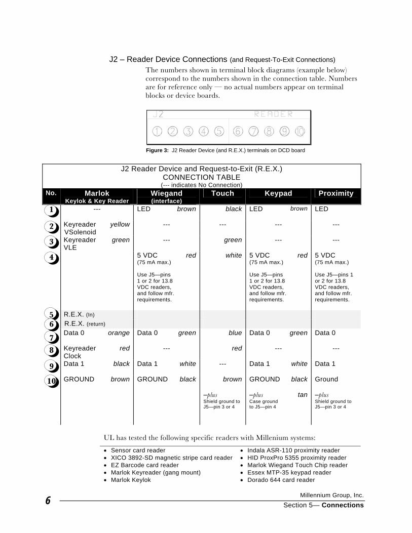
J2 – Reader Device Connections (and Request-To-Exit Connections) The numbers shown in terminal block diagrams (example below) correspond to the numbers shown in the connection table. Numbers are for reference only — no actual numbers appear on terminal blocks or device boards.
J2 Reader Device and Request-to-Exit (R.E.X.)
CONNECTION TABLE (--- indicates No Connection)
No. Marlok Keylok & Key Reader
Wiegand (interface)
Touch Keypad Proximity
1 --- LED brown black LED brown LED
2 Keyreader VSolenoid
yellow --- --- --- ---
3 Keyreader VLE
green --- green --- ---
4
5 VDC (75 mA max.) Use J5—pins 1 or 2 for 13.8 VDC readers, and follow mfr. requirements.
red white 5 VDC (75 mA max.) Use J5—pins 1 or 2 for 13.8 VDC readers, and follow mfr. requirements.
red 5 VDC (75 mA max.) Use J5—pins 1 or 2 for 13.8 VDC readers, and follow mfr. requirements.
5 R.E.X. (In) 6 R.E.X. (return)
7 Data 0 orange Data 0 green blue Data 0 green Data 0
8 Keyreader
Clock red --- red --- ---
9 Data 1 black Data 1 white --- Data 1 white Data 1
10 GROUND brown GROUND black brown –plus Shield ground to J5—pin 3 or 4
GROUND –plus Case ground to J5—pin 4
black
tan
Ground –plus Shield ground to J5—pin 3 or 4
UL has tested the following specific readers with Millenium systems:
• Sensor card reader • Indala ASR-110 proximity reader • XICO 3892-SD magnetic stripe card reader • HID ProxPro 5355 proximity reader • EZ Barcode card reader • Marlok Wiegand Touch Chip reader • Marlok Keyreader (gang mount) • Essex MTP-35 keypad reader • Marlok Keylok • Dorado 644 card reader
Figure 3: J2 Reader Device (and R.E.X.) terminals on DCD board
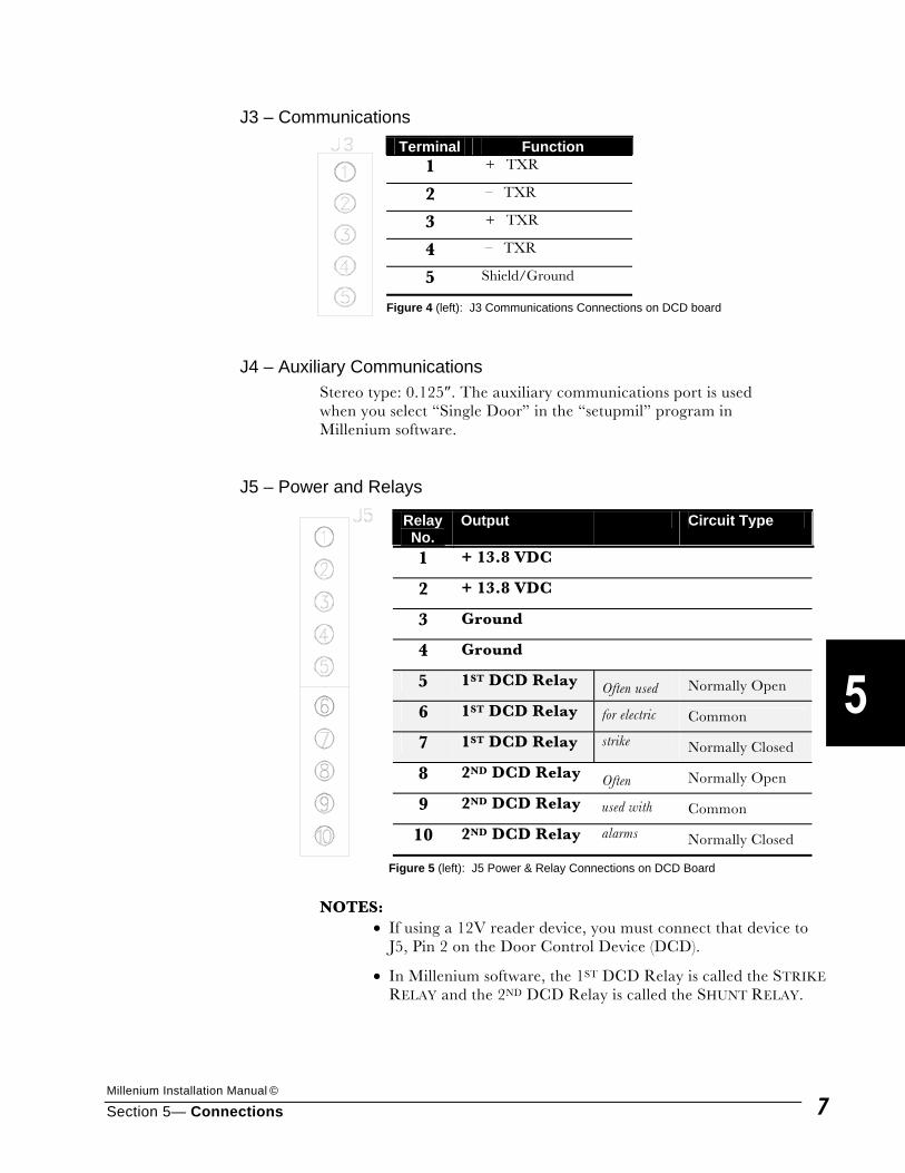
Millenium Installation Manual ©
Section 5— Connections 7
J3 – Communications Terminal Function
1 + TXR
2 – TXR
3 + TXR
4 – TXR
5 Shield/Ground
Figure 4 (left): J3 Communications Connections on DCD board
J4 – Auxiliary Communications Stereo type: 0.125″. The auxiliary communications port is used when you select “Single Door” in the “setupmil” program in Millenium software.
J5 – Power and Relays
Figure 5 (left): J5 Power & Relay Connections on DCD Board
NOTES:
• If using a 12V reader device, you must connect that device to J5, Pin 2 on the Door Control Device (DCD).
• In Millenium software, the 1ST DCD Relay is called the STRIKE RELAY and the 2ND DCD Relay is called the SHUNT RELAY.
Relay No.
Output Circuit Type
1 + 13.8 VDC
2 + 13.8 VDC
3 Ground
4 Ground
5 1ST DCD Relay Often used Normally Open
6 1ST DCD Relay for electric Common
7 1ST DCD Relay strike Normally Closed
8 2ND DCD Relay Often Normally Open
9 2ND DCD Relay used with Common
10 2ND DCD Relay alarms Normally Closed
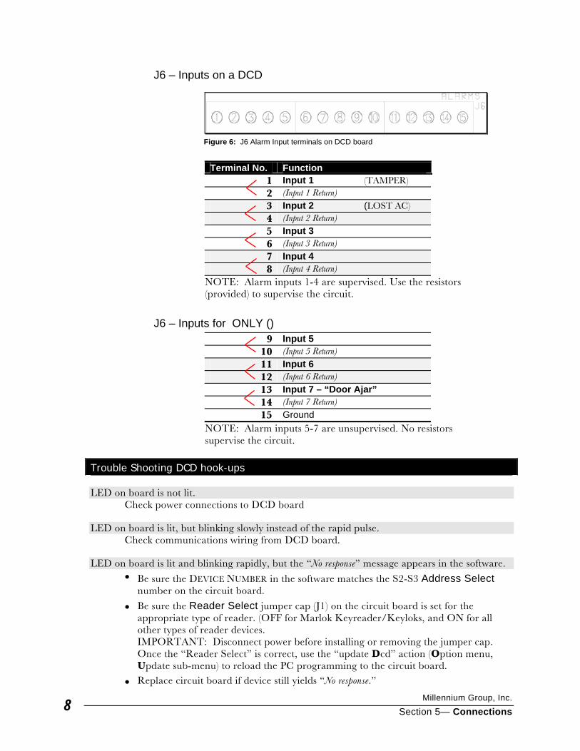
Millennium Group, Inc.
Section 5— Connections 8
J6 – Inputs on a DCD
Terminal No. Function
1 Input 1 (TAMPER) 2 (Input 1 Return) 3 Input 2 (LOST AC) 4 (Input 2 Return) 5 Input 3 6 (Input 3 Return) 7 Input 4 8 (Input 4 Return)
NOTE: Alarm inputs 1-4 are supervised. Use the resistors (provided) to supervise the circuit.
J6 – Inputs for ONLY ()
9 Input 5 10 (Input 5 Return) 11 Input 6 12 (Input 6 Return) 13 Input 7 – “Door Ajar” 14 (Input 7 Return) 15 Ground
NOTE: Alarm inputs 5-7 are unsupervised. No resistors supervise the circuit.
Trouble Shooting DCD hook-ups
LED on board is not lit. Check power connections to DCD board
LED on board is lit, but blinking slowly instead of the rapid pulse. Check communications wiring from DCD board.
LED on board is lit and blinking rapidly, but the “No response” message appears in the software. • Be sure the DEVICE NUMBER in the software matches the S2-S3 Address Select
number on the circuit board.
• Be sure the Reader Select jumper cap (J1) on the circuit board is set for the appropriate type of reader. (OFF for Marlok Keyreader/Keyloks, and ON for all other types of reader devices. IMPORTANT: Disconnect power before installing or removing the jumper cap. Once the “Reader Select” is correct, use the “update Dcd” action (Option menu, Update sub-menu) to reload the PC programming to the circuit board.
• Replace circuit board if device still yields “No response.”
Figure 6: J6 Alarm Input terminals on DCD board
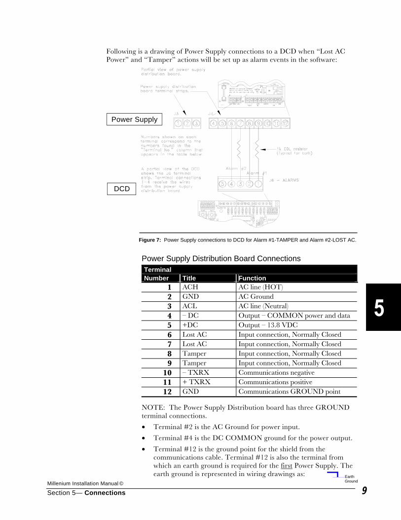
Millenium Installation Manual ©
Section 5— Connections 9
Following is a drawing of Power Supply connections to a DCD when “Lost AC Power” and “Tamper” actions will be set up as alarm events in the software:
Power Supply Distribution Board Connections Terminal Number Title Function
1 ACH AC line (HOT) 2 GND AC Ground 3 ACL AC line (Neutral) 4 – DC Output – COMMON power and data 5 +DC Output – 13.8 VDC 6 Lost AC Input connection, Normally Closed 7 Lost AC Input connection, Normally Closed 8 Tamper Input connection, Normally Closed 9 Tamper Input connection, Normally Closed
10 – TXRX Communications negative 11 + TXRX Communications positive 12 GND Communications GROUND point
NOTE: The Power Supply Distribution board has three GROUND terminal connections.
• Terminal #2 is the AC Ground for power input.
• Terminal #4 is the DC COMMON ground for the power output.
• Terminal #12 is the ground point for the shield from the communications cable. Terminal #12 is also the terminal from which an earth ground is required for the first Power Supply. The earth ground is represented in wiring drawings as:
Figure 7: Power Supply connections to DCD for Alarm #1-TAMPER and Alarm #2-LOST AC.
EarthGround
Power Supply
DCD
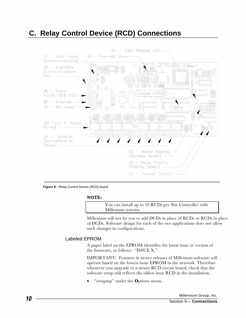
Millennium Group, Inc.
Section 5— Connections 10
C. Relay Control Device (RCD) Connections
NOTE:
You can install up to 10 RCDs per Site Controller with Millenium systems.
Millenium will not let you to add DCDs in place of RCDs or RCDs in place of DCDs. Software design for each of the two applications does not allow such changes in configurations.
Labeled EPROM A paper label on the EPROM identifies the latest issue or version of the firmware, as follows: “ISSUE X.”
IMPORTANT: Features in newer releases of Millenium software will operate based on the lowest-issue EPROM in the network. Therefore whenever you upgrade to a newer RCD circuit board, check that the software setup still reflects the oldest issue RCD in the installation.
• “setupmp” under the Options menu.
Figure 8: Relay Control Device (RCD) board
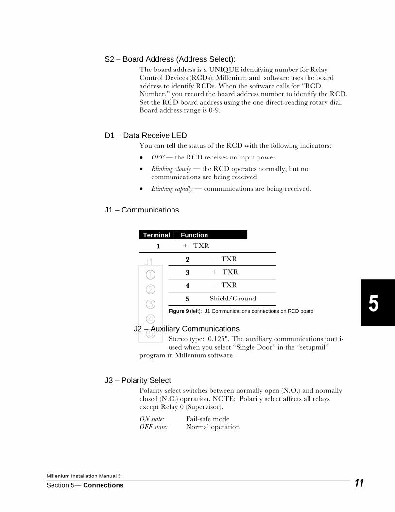
Millenium Installation Manual ©
Section 5— Connections 11
S2 – Board Address (Address Select):
The board address is a UNIQUE identifying number for Relay Control Devices (RCDs). Millenium and software uses the board address to identify RCDs. When the software calls for “RCD Number,” you record the board address number to identify the RCD. Set the RCD board address using the one direct-reading rotary dial. Board address range is 0-9.
D1 – Data Receive LED You can tell the status of the RCD with the following indicators:
• OFF — the RCD receives no input power
• Blinking slowly — the RCD operates normally, but no communications are being received
• Blinking rapidly — communications are being received.
J1 – Communications Terminal Function
1 + TXR
2 – TXR
3 + TXR
4 – TXR
5 Shield/Ground
Figure 9 (left): J1 Communications connections on RCD board
J2 – Auxiliary Communications
Stereo type: 0.125". The auxiliary communications port is used when you select “Single Door” in the “setupmil”
program in Millenium software.
J3 – Polarity Select Polarity select switches between normally open (N.O.) and normally closed (N.C.) operation. NOTE: Polarity select affects all relays except Relay 0 (Supervisor).
ON state: Fail-safe mode OFF state: Normal operation
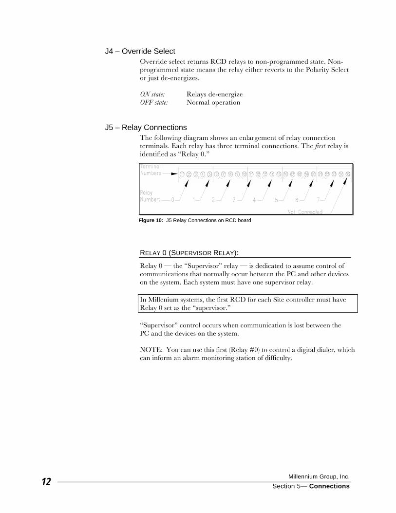
Millennium Group, Inc.
Section 5— Connections 12
J4 – Override Select Override select returns RCD relays to non-programmed state. Non-programmed state means the relay either reverts to the Polarity Select or just de-energizes. ON state: Relays de-energize OFF state: Normal operation
J5 – Relay Connections The following diagram shows an enlargement of relay connection terminals. Each relay has three terminal connections. The first relay is identified as “Relay 0.”
RELAY 0 (SUPERVISOR RELAY):
Relay 0 — the “Supervisor” relay — is dedicated to assume control of communications that normally occur between the PC and other devices on the system. Each system must have one supervisor relay. In Millenium systems, the first RCD for each Site controller must have Relay 0 set as the “supervisor.” “Supervisor” control occurs when communication is lost between the PC and the devices on the system. NOTE: You can use this first (Relay #0) to control a digital dialer, which can inform an alarm monitoring station of difficulty.
Figure 10: J5 Relay Connections on RCD board
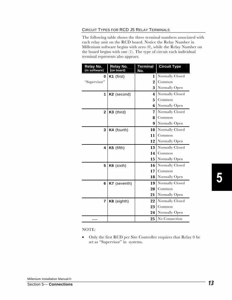
Millenium Installation Manual ©
Section 5— Connections 13
CIRCUIT TYPES FOR RCD J5 RELAY TERMINALS
The following table shows the three terminal numbers associated with each relay unit on the RCD board. Notice the Relay Number in Millenium software begins with zero (0), while the Relay Number on the board begins with one (1). The type of circuit each individual terminal represents also appears.
Relay No. (in software)
Relay No. (on board)
Terminal No.
Circuit Type
0 K1 (first) 1 Normally Closed
“Supervisor” 2 Common
3 Normally Open
1 K2 (second) 4 Normally Closed
5 Common
6 Normally Open
2 K3 (third) 7 Normally Closed
8 Common
9 Normally Open
3 K4 (fourth) 10 Normally Closed
11 Common
12 Normally Open
4 K5 (fifth) 13 Normally Closed
14 Common
15 Normally Open
5 K6 (sixth) 16 Normally Closed
17 Common
18 Normally Open
6 K7 (seventh) 19 Normally Closed
20 Common
21 Normally Open
7 K8 (eighth) 22 Normally Closed
23 Common
24 Normally Open
.... 25 No Connection
NOTE:
• Only the first RCD per Site Controller requires that Relay 0 be set as “Supervisor” in systems.
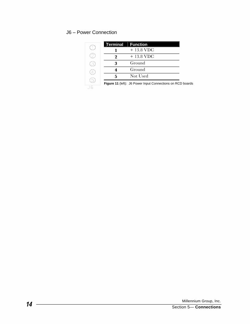
Millennium Group, Inc.
Section 5— Connections 14
J6 – Power Connection
Terminal Function 1 + 13.8 VDC
2 + 13.8 VDC
3 Ground
4 Ground
5 Not Used
Figure 11 (left): J6 Power Input Connections on RCD boards
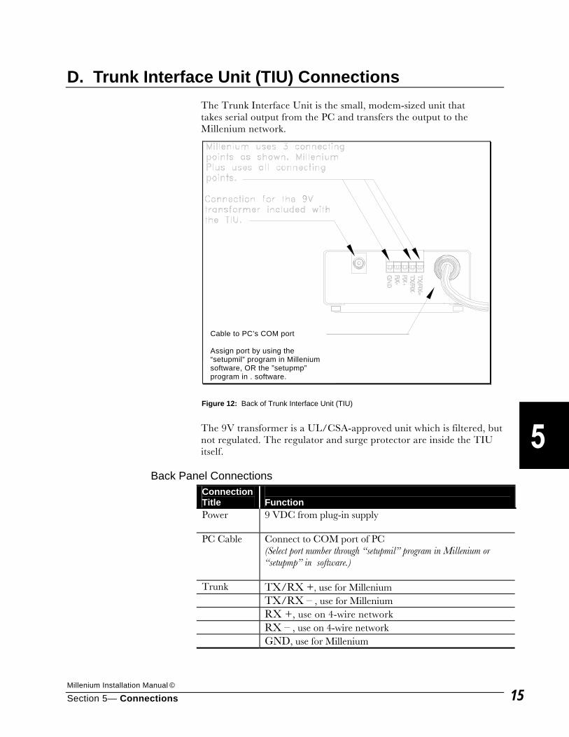
Millenium Installation Manual ©
Section 5— Connections 15
D. Trunk Interface Unit (TIU) Connections
The Trunk Interface Unit is the small, modem-sized unit that takes serial output from the PC and transfers the output to the Millenium network.
The 9V transformer is a UL/CSA-approved unit which is filtered, but not regulated. The regulator and surge protector are inside the TIU itself.
Back Panel Connections Connection Title
Function
Power 9 VDC from plug-in supply
PC Cable Connect to COM port of PC (Select port number through “setupmil” program in Millenium or “setupmp” in software.)
Trunk TX/RX +, use for Millenium TX/RX – , use for Millenium RX +, use on 4-wire network RX – , use on 4-wire network GND, use for Millenium
Figure 12: Back of Trunk Interface Unit (TIU)
Cable to PC’s COM port Assign port by using the “setupmil” program in Millenium software, OR the ”setupmp” program in . software.
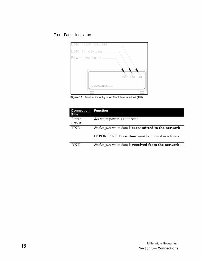
Millennium Group, Inc.
Section 5— Connections 16
Front Panel Indicators
Connection Title
Function
Power (PWR)
Red when power is connected.
TXD Flashes green when data is transmitted to the network. IMPORTANT–First door must be created in software.
RXD Flashes green when data is received from the network.
Figure 13: Front Indicator lights on Trunk Interface Unit (TIU)
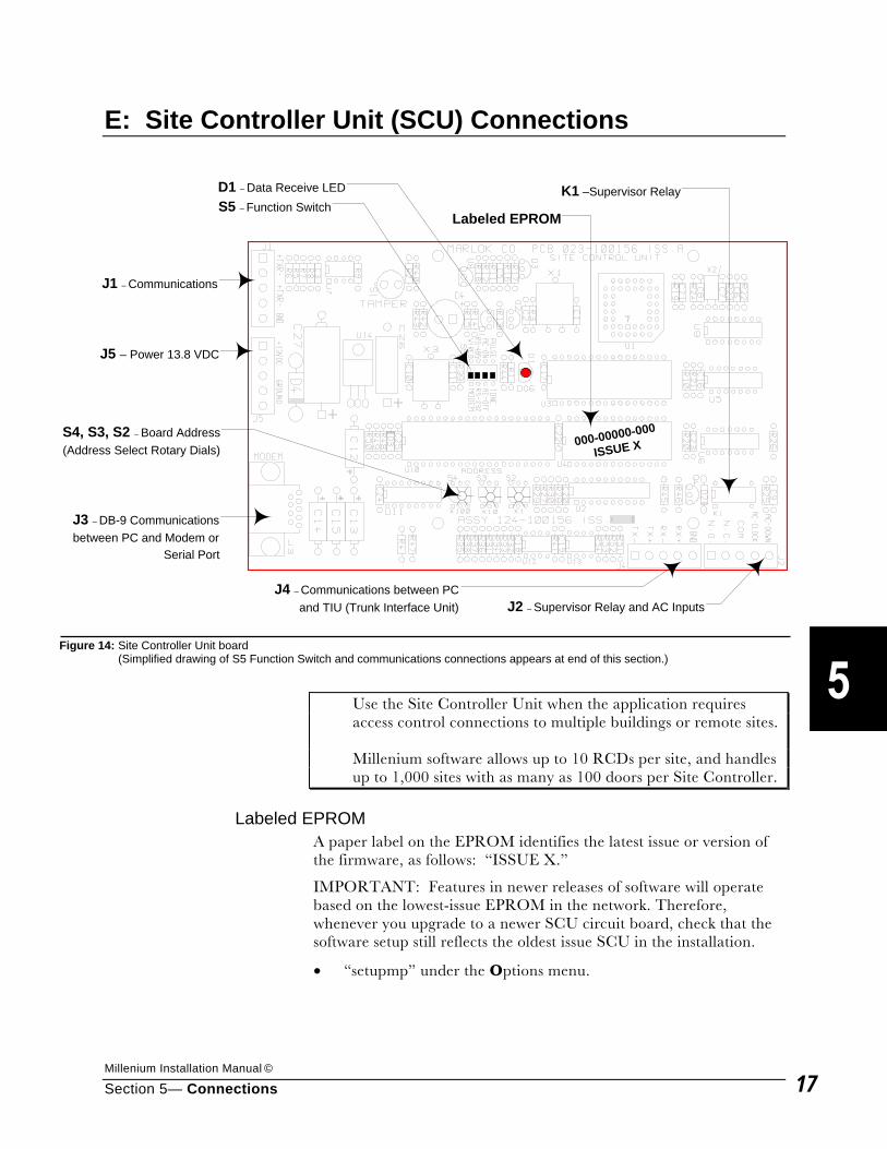
Millenium Installation Manual ©
Section 5— Connections 17
E: Site Controller Unit (SCU) Connections
Use the Site Controller Unit when the application requires
access control connections to multiple buildings or remote sites. Millenium software allows up to 10 RCDs per site, and handles
up to 1,000 sites with as many as 100 doors per Site Controller.
Labeled EPROM A paper label on the EPROM identifies the latest issue or version of the firmware, as follows: “ISSUE X.”
IMPORTANT: Features in newer releases of software will operate based on the lowest-issue EPROM in the network. Therefore, whenever you upgrade to a newer SCU circuit board, check that the software setup still reflects the oldest issue SCU in the installation.
• “setupmp” under the Options menu.
000-00000-000
ISSUE X
J1 – Communications
J5 – Power 13.8 VDC
D1 – Data Receive LEDS5 – Function Switch
S4, S3, S2 – Board Address(Address Select Rotary Dials)
Labeled EPROM
J4 – Communications between PCand TIU (Trunk Interface Unit) J2 – Supervisor Relay and AC Inputs
J3 – DB-9 Communicationsbetween PC and Modem or
Serial Port
K1 –Supervisor Relay
Figure 14: Site Controller Unit board (Simplified drawing of S5 Function Switch and communications connections appears at end of this section.)
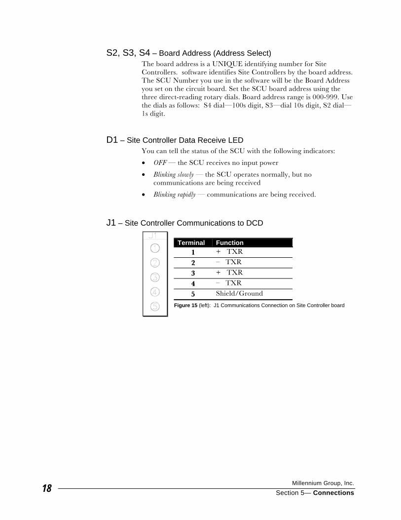
Millennium Group, Inc.
Section 5— Connections 18
S2, S3, S4 – Board Address (Address Select) The board address is a UNIQUE identifying number for Site Controllers. software identifies Site Controllers by the board address. The SCU Number you use in the software will be the Board Address you set on the circuit board. Set the SCU board address using the three direct-reading rotary dials. Board address range is 000-999. Use the dials as follows: S4 dial—100s digit, S3—dial 10s digit, S2 dial—1s digit.
D1 – Site Controller Data Receive LED You can tell the status of the SCU with the following indicators:
• OFF — the SCU receives no input power
• Blinking slowly — the SCU operates normally, but no communications are being received
• Blinking rapidly — communications are being received.
J1 – Site Controller Communications to DCD Terminal Function
1 + TXR
2 – TXR
3 + TXR
4 – TXR
5 Shield/Ground
Figure 15 (left): J1 Communications Connection on Site Controller board
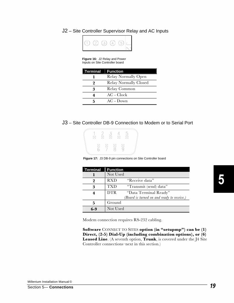
Millenium Installation Manual ©
Section 5— Connections 19
J2 – Site Controller Supervisor Relay and AC Inputs
Terminal Function 1 Relay Normally Open
2 Relay Normally Closed
3 Relay Common
4 AC - Clock
5 AC - Down
J3 – Site Controller DB-9 Connection to Modem or to Serial Port
Terminal Function
1 Not Used
2 RXD “Receive data”
3 TXD “Transmit (send) data”
4 DTR “Data Terminal Ready” (Board is turned on and ready to receive.)
5 Ground
6-9 Not Used
Modem connection requires RS-232 cabling. Software CONNECT TO SITES option (in “setupmp”) can be (1) Direct, (2-5) Dial-Up (including combination options), or (6) Leased Line. (A seventh option, Trunk, is covered under the J4 Site Controller connections–next in this section.)
Figure 16: J2 Relay and Power Inputs on Site Controller board
Figure 17: J3 DB-9 pin connections on Site Controller board
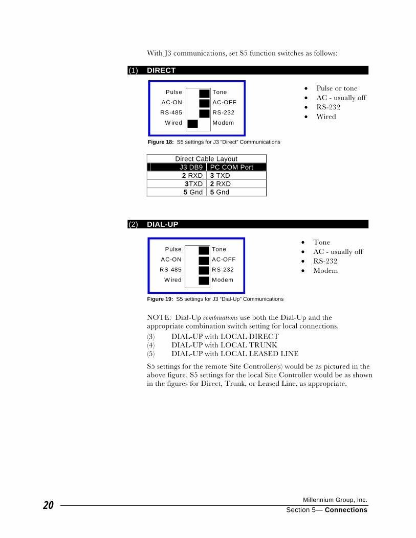
Millennium Group, Inc.
Section 5— Connections 20
With J3 communications, set S5 function switches as follows:
(1) DIRECT • Pulse or tone • AC - usually off • RS-232 • Wired
Direct Cable Layout J3 DB9 PC COM Port 2 RXD 3 TXD 3TXD 2 RXD 5 Gnd 5 Gnd
(2) DIAL-UP
• Tone • AC - usually off • RS-232 • Modem
NOTE: Dial-Up combinations use both the Dial-Up and the appropriate combination switch setting for local connections. (3) DIAL-UP with LOCAL DIRECT (4) DIAL-UP with LOCAL TRUNK (5) DIAL-UP with LOCAL LEASED LINE
S5 settings for the remote Site Controller(s) would be as pictured in the above figure. S5 settings for the local Site Controller would be as shown in the figures for Direct, Trunk, or Leased Line, as appropriate.
Pulse
AC-ON
RS-485
W ired
Tone
AC-OFF
RS-232
Modem
Figure 18: S5 settings for J3 “Direct” Communications
Pulse
AC-ON
RS-485
W ired
Tone
AC-OFF
RS-232
Modem
Figure 19: S5 settings for J3 “Dial-Up” Communications
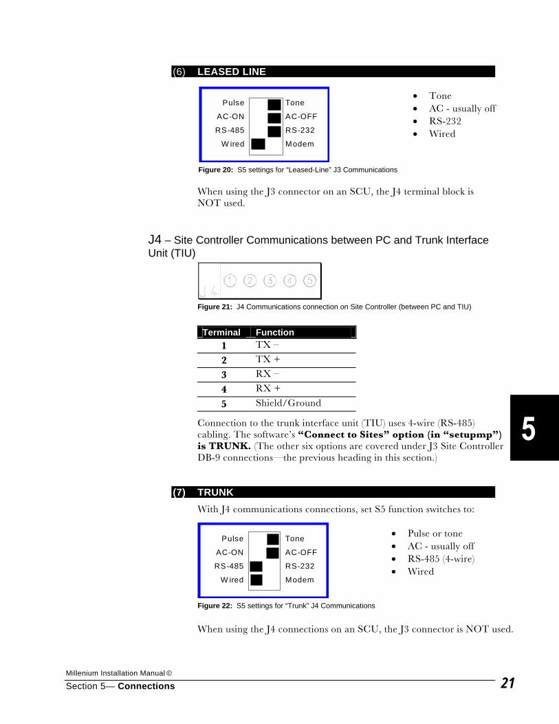
Millenium Installation Manual ©
Section 5— Connections 21
(6) LEASED LINE • Tone • AC - usually off • RS-232 • Wired
When using the J3 connector on an SCU, the J4 terminal block is NOT used.
J4 – Site Controller Communications between PC and Trunk Interface Unit (TIU)
Terminal Function
1 TX –
2 TX +
3 RX –
4 RX +
5 Shield/Ground
Connection to the trunk interface unit (TIU) uses 4-wire (RS-485) cabling. The software’s “Connect to Sites” option (in “setupmp”) is TRUNK. (The other six options are covered under J3 Site Controller DB-9 connections—the previous heading in this section.)
(7) TRUNK With J4 communications connections, set S5 function switches to:
• Pulse or tone • AC - usually off • RS-485 (4-wire) • Wired
When using the J4 connections on an SCU, the J3 connector is NOT used.
Pulse
AC-ON
RS-485
W ired
Tone
AC-OFF
RS-232
Modem
Figure 20: S5 settings for “Leased-Line” J3 Communications
Figure 21: J4 Communications connection on Site Controller (between PC and TIU)
Pulse
AC-ON
RS-485
W ired
Tone
AC-OFF
RS-232
Modem
Figure 22: S5 settings for “Trunk” J4 Communications
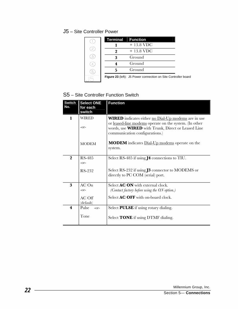
Millennium Group, Inc.
Section 5— Connections 22
J5 – Site Controller Power Terminal Function
1 + 13.8 VDC
2 + 13.8 VDC
3 Ground
4 Ground
5 Ground
Figure 23 (left): J5 Power connection on Site Controller board
S5 – Site Controller Function Switch Switch No.
Select ONE for each switch
Function
1 WIRED -or-
MODEM
WIRED indicates either no Dial-Up modems are in use or leased-line modems operate on the system. (In other words, use WIRED with Trunk, Direct or Leased Line communication configurations.) MODEM indicates Dial-Up modems operate on the system.
2 RS-485 -or-
RS-232
Select RS-485 if using J4 connections to TIU.
Select RS-232 if using J3 connector to MODEMS or directly to PC COM (serial) port.
3 AC On -or-
AC Off (default)
Select AC ON with external clock. (Contact factory before using the ON option.)
Select AC OFF with on-board clock.
4 Pulse -or-
Tone
Select PULSE if using rotary dialing. Select TONE if using DTMF dialing.
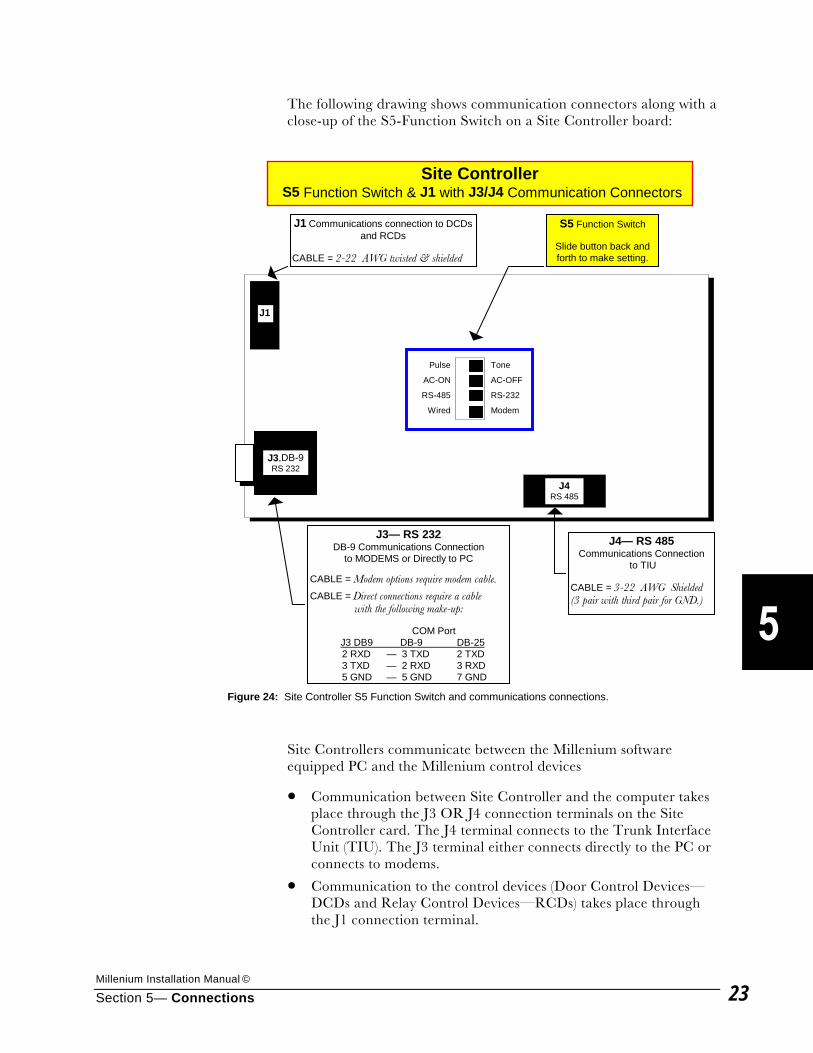
Millenium Installation Manual ©
Section 5— Connections 23
The following drawing shows communication connectors along with a close-up of the S5-Function Switch on a Site Controller board:
Site Controllers communicate between the Millenium software equipped PC and the Millenium control devices
• Communication between Site Controller and the computer takes place through the J3 OR J4 connection terminals on the Site Controller card. The J4 terminal connects to the Trunk Interface Unit (TIU). The J3 terminal either connects directly to the PC or connects to modems.
• Communication to the control devices (Door Control Devices— DCDs and Relay Control Devices—RCDs) takes place through the J1 connection terminal.
Site Controller S5 Function Switch & J1 with J3/J4 Communication Connectors
Pulse
AC-ON
RS-485
Wired
Tone
AC-OFF
RS-232
Modem
J1 Communications connection to DCDsand RCDs
CABLE = 2-22 AWG twisted & shielded
J3— RS 232DB-9 Communications Connection
to MODEMS or Directly to PC
CABLE = Modem options require modem cable.
CABLE = Direct connections require a cable with the following make-up:
COM PortJ3 DB9 DB-9 DB-252 RXD — 3 TXD 2 TXD3 TXD — 2 RXD 3 RXD5 GND — 5 GND 7 GND
J4— RS 485Communications Connection
to TIU
CABLE = 3-22 AWG Shielded(3 pair with third pair for GND.)
J3,DB-9RS 232
S5 Function Switch
Slide button back andforth to make setting.
J4RS 485
J1
Figure 24: Site Controller S5 Function Switch and communications connections.

Millennium Group, Inc.
Section 5— Connections 24
() Seven “Connect to Sites” options exist in the software. (Under “Options” in the “setupmp” program):
• Trunk
• Direct
• Dial Up
• Dial Up with Local Direct
• Dial Up with Local Leased Line
• Dial Up with Local Trunk
• Leased Line Select one of the options, depending on an application’s site requirements: J4 (RS-485, 4-wire) connects to Trunk Interface Unit (TIU)
Software configuration = TRUNK J3 (RS-232) connects to one of the following:
• MODEM
Software configuration = DIALUP (including any of the dial-up combinations) or LEASED LINE
• Directly to the PC Computer’s serial port Software configuration = DIRECT
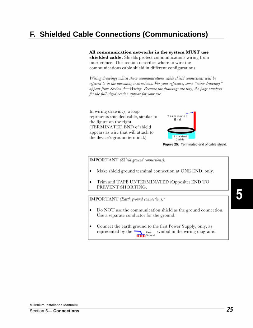
Millenium Installation Manual ©
Section 5— Connections 25
F. Shielded Cable Connections (Communications) All communication networks in the system MUST use shielded cable. Shields protect communications wiring from interference. This section describes where to wire the communications cable shield in different configurations. Wiring drawings which show communications cable shield connections will be referred to in the upcoming instructions. For your reference, some “mini-drawings” appear from Section 4—Wiring. Because the drawings are tiny, the page numbers for the full-sized version appear for your use.
In wiring drawings, a loop represents shielded cable, similar to the figure on the right. (TERMINATED END of shield appears as wire that will attach to the device’s ground terminal.)
IMPORTANT (Shield ground connections): • Make shield ground terminal connection at ONE END, only. • Trim and TAPE UNTERMINATED (Opposite) END TO
PREVENT SHORTING. IMPORTANT (Earth ground connections): • Do NOT use the communication shield as the ground connection.
Use a separate conductor for the ground. • Connect the earth ground to the first Power Supply, only, as
represented by the symbol in the wiring diagrams.
T e rm in a te dE n d
S h ie ld e dC a b le
Figure 25: Terminated end of cable shield.
Earth Ground
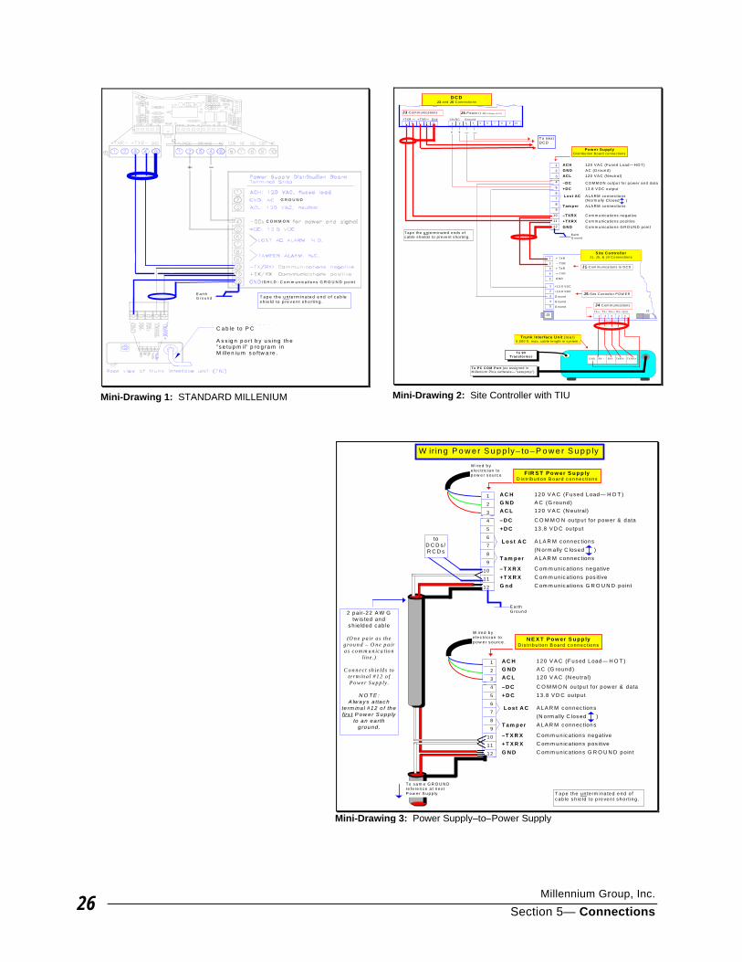
Millennium Group, Inc.
Section 5— Connections 26
C a b le to P C
A s s ig n p o r t b y u s in g th e”s e tu p m il” p ro g ra m inM ille n iu m s o ftw a re .
T a p e th e u n te rm in a te d e n d o f c a b les h ie ld to p re v e n t s h o rt in g .
/S H L D : C o m m u n ic a tio n s G R O U N D p o in t
C O M M O N
G R O U N D
E a r thG ro u n d
Mini-Drawing 1: STANDARD MILLENIUM
+T XR — +T X R — G nd
J3 -C om m unications J5 -P ower (1 -4) & R elays (5-10)
AC H 120 V A C (Fused Load— H O T)G N D A C (G round)AC L 120 V A C (N eutra l)
–D C C O M M O N output for power and data+D C 13.8 V D C output
Lost AC A LA R M connec tions(N orm ally C losed )
Tam per A LA R M connec tions
–TX R X C om m unications negative+TX R X C om m unications pos itiveG N D C om m unications G R O U N D po in t
P o w er S u pplyD istribu tion B oard connections
1 2 3 4 5 6 7 8 9 10
1
2
3
4
5
1
2
3
4
5
J3
J1 -C om m unications to D C D
J5 -S ite C ontro lle r P O W E R
+ T XR
— T XR
+ T XR
— T XR
G N D
+13.8 V D C
+13.8 V D C
G round
G round
G round
1
2
3
4
5
6
7
8
9
10
11
12
+ + — —
J2
Trunk In terface U n it (rear)5 ,000 ft. m ax. cab le length in system .
1 2 3 4 5
J4 -C om m unications
T X— T X+ R X— R X+ G nd
1 2 3 4 513V D C G round
D C DJ3 and J5 C onnections
To nextD C D
To P C C O M P ort (as assigned inM illen ium P lus software— “setupm p”)
To 9VTransform er
G N D R X – R X+ T X/R X– T X/R X+
Tape the unterm inated ends o fcab le sh ie lds to prevent shorting.
S ite C ontro llerJ1, J5 , & J4 C onnections
E arthG round
Mini-Drawing 2: Site Controller with TIU
W ir in g P o w e r S u p p ly– to – P o w e r S u p p ly
A C H 120 V A C (F us ed Load— H O T )G N D A C (G round)A C L 120 V A C (N eu tral)
–D C C O M M O N ou tpu t for pow er & data+ D C 13 .8 V D C ou tpu t
L o s t A C A LA R M c onnec tions(N orm ally C los ed )
T am p er A LA R M c onnec tions
–T X R X C om m un ic ations negative+ T X R X C om m un ic ations pos itiveG n d C om m un ic ations G R O U N D poin t
F IR S T P o w er S u p p lyD is tr ibu tion B o a rd c on ne c tio ns
A C H 120 V A C (F us ed Load— H O T )G N D A C (G round )A C L 120 V A C (N eu tral)
–D C C O M M O N ou tpu t for pow er & data+ D C 13 .8 V D C ou tpu t
L o s t A C A LA R M c onnec tions(N orm ally C los ed )
T am p er A LA R M c onnec tions
–T X R X C om m un ic ations negative+ T X R X C om m un ic ations pos itiveG N D C om m un ic ations G R O U N D poin t
N E X T P o w er S u p p lyD is tr ib u tio n B oa rd c o nn ec tion s
1
2
3
4
5
6
7
8
9
10
11
12
W ire d b ye le c tric ia n top o w e r s o u rc e
To s a m e G R O U N Dre fe re n c e a t n e xtP o w e r S u p p ly
1
2
3
4
5
6
7
8
9
1 0
1 1
1 2
W ire d b ye le c tric ia n top o w e r s o u rc e .
2 pair-22 A W Gtw is ted and
s h ielded c ab le
(O n e p a ir a s th eg ro u n d – O n e p a ira s c o m m u n ic a tio n
lin e .)
C o n n e c t sh ie ld s tote rm in a l # 1 2 o fPo w e r S u p p ly .
N O T E :A lw ay s a ttac h
te rm ina l #12 o f thefirs t P ow er S upp ly
to an ea rthg round .
toD C D s /R C D s
E a rthG ro u n d
T a pe th e un te rm ina te d e nd o fc ab le s h ie ld to p reven t s h o r ting .
Mini-Drawing 3: Power Supply–to–Power Supply
Millenium Installation Manual ©
Section 5— Connections 27
Connect the cable shields to the particular devices as described in the following examples. PC TRUNK INTERFACE UNIT (TIU) TO POWER SUPPLY
1. Connect the TIU communications shield to Power Supply terminal #12.
(Refer to Mini-Drawing #1 on the facing page. Full-sized “Wiring Diagram: Standard Millenium” is in Section 4—Wiring, page 13.)
Connect the TIU communications shield to the J4–Communications terminal (#5–GND) on the Site Controller terminal #5. (Refer to Mini-Drawing #2 on the facing page. Full-sized “Wiring Diagram: (Site Controller with TIU)” is in Section 4—Wiring, page 16.)
2. Tape the unterminated end of the shield to prevent it from coming in contact with ground or other components. Be sure only one end of the cable makes the shield ground connection.
3. Do not use the communications shield as the ground connection for power between the Trunk Interface Unit (TIU) and the power supply. Use a separate conductor for the ground.
POWER SUPPLY TO POWER SUPPLY
1. Connect the second pair of the 2-pair cable to terminal #12 of each Power Supply. Strip and twist this pair together to act as a single conductor. This connection will continue the GROUND reference to subsequent power supplies in the configuration, as long as you make the connection to terminal #12 in each power supply.
(Refer to Mini-Drawing #3 on the facing page. Full-sized “Wiring Diagram: Power Supply–to–Power Supply” is in Section 4—Wiring, page 14.)
2. Tape unterminated end of the communications shield to prevent it from coming in contact with ground or other components. Be sure only one end of the cable makes the shield ground connection.
3. Do not use the communications shield as the ground connection for power between power supplies. Use a separate conductor for the ground.

Millennium Group, Inc.
Section 5— Connections 28
SITE CONTROLLER TO POWER SUPPLY
1. Connect Site Controller shield to Power Supply terminal #12.
(Refer to drawing on facing page.)
2. Tape the unterminated end of the shield to prevent it from coming in contact with ground or other components. Be sure only one end of the cable makes the shield ground connection.
3. Do not use the communications shield as the ground connection for power between Site Controller and the Power Supply.
POWER SUPPLY TO DCD OR RCD (OR FIRST DEVICE OF A MULTIPLE — OR “DAISY” CHAIN)
1. Connect communication shield from the Power Supply to the DCD (or RCD) J3-Communications terminal #5 (GND).
(Refer to drawing on facing page.)
2. Tape the unterminated end of the communications shield to prevent it from coming in contact with ground or other components. Be sure only one end of the cable makes the shield ground connection.
3. Do not use the communications shield as the ground connection for power between the Power Supply and the DCD or RCD. Use a separate conductor.
DCD TO DCD (“DAISY-CHAINED” CONNECTIONS)
Daisy-chained devices are multiple DCDs connected from one to another.
1. When DCDs are “daisy chained” together, you must connect the communications from the Power Supply to the first device.
(#1 in drawing on facing page)
2. Connect communication shield of subsequent “daisy-chained” DCDs to one DCD only (#2 in drawing on facing page). The last DCD in the chain needs no shield connection.
3. Do not use the communication shield as the ground connection for power between DCDs. Use a separate conductor.
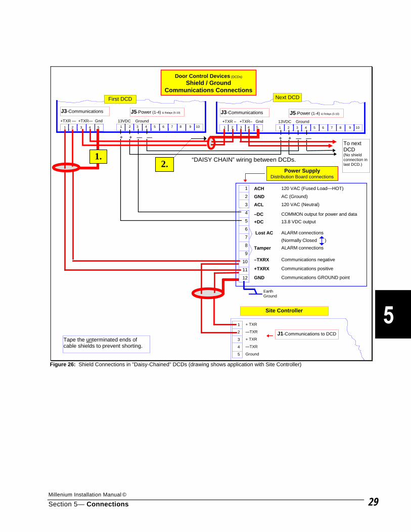
Millenium Installation Manual ©
Section 5— Connections 29
+TXR — +TXR— Gnd
Door Control Devices (DCDs)
Shield / GroundCommunications Connections
J3-Communications J5-Power (1-4) & Relays (5-10)
ACH 120 VAC (Fused Load—HOT)
GND AC (Ground)
ACL 120 VAC (Neutral)
–DC COMMON output for power and data+DC 13.8 VDC output
Lost AC ALARM connections(Normally Closed )
Tamper ALARM connections
–TXRX Communications negative
+TXRX Communications positive
GND Communications GROUND point
Power SupplyDistribution Board connections
1 2 3 4 5 6 7 8 9 10
J3-Communications J5-Power (1-4) & Relays (5-10)
Site Controller
1
2
3
4
5
J1-Communications to DCD
+ TXR
—TXR
+ TXR
—TXR
Ground
1
2
3
4
5
6
7
8
9
10
11
12
+ + — — + + — —
“DAISY CHAIN” wiring between DCDs.
1 2 3 4 5
13VDC Ground
First DCD
1.2.
Next DCD
To nextDCD(No shieldconnection inlast DCD.)
1 2 3 4 5 6 7 8 9 101 2 3 4 5
+TXR – +TXR– Gnd 13VDC Ground
Tape the unterminated ends ofcable shields to prevent shorting.
EarthGround
Figure 26: Shield Connections in "Daisy-Chained" DCDs (drawing shows application with Site Controller)

Millennium Group, Inc.
Section 5— Connections 30
This Page Intentionally Left Blank
Millenium Installation Manual ©
Section 6— Preparing Doors & Installing Readers 1
Preparing Doors & Installing Readers This section is divided into three parts:
A. Procedures for Preparing Doors B. Instructions for Installing Reader devices C. Hinge Installation
Before you begin:
Read this entire section before proceeding with any door preparation.
Use the following definitions as part of the instruction procedures:
• Exterior refers to the side of the door with the Keylok.
• Interior refers to the unsecured side of the door.
• Bezel refers to the threaded sleeve that receives the mortise lock.
• Leader Cable connects Marlok Keyloks/Keyreader unit to the Door Control Device (DCD).
Recommended Keyreader and Keylok leader cable length is 15 feet. Maximum length is 35 feet if the cable runs in its own conduit—not bundled with other wires. 35-foot cables bundled with other wires experience interference.
• Pigtail refers to a short cable that will attach most reader devices (those without terminal connections) to the Leader Cable. Leader cable then connects to the DCD.
Adjusting Marlok Keyloks:
Before installation, Marlok Keyloks require a rotation adjustment and test to verify proper operation of the barrel. Refer to the drawing and instructions on the next page.
Before rotation, the key will not turn because all Keyloks are shipped locked down.
Once power is applied, the Keylok’s green LED should light when the “C” key is inserted.
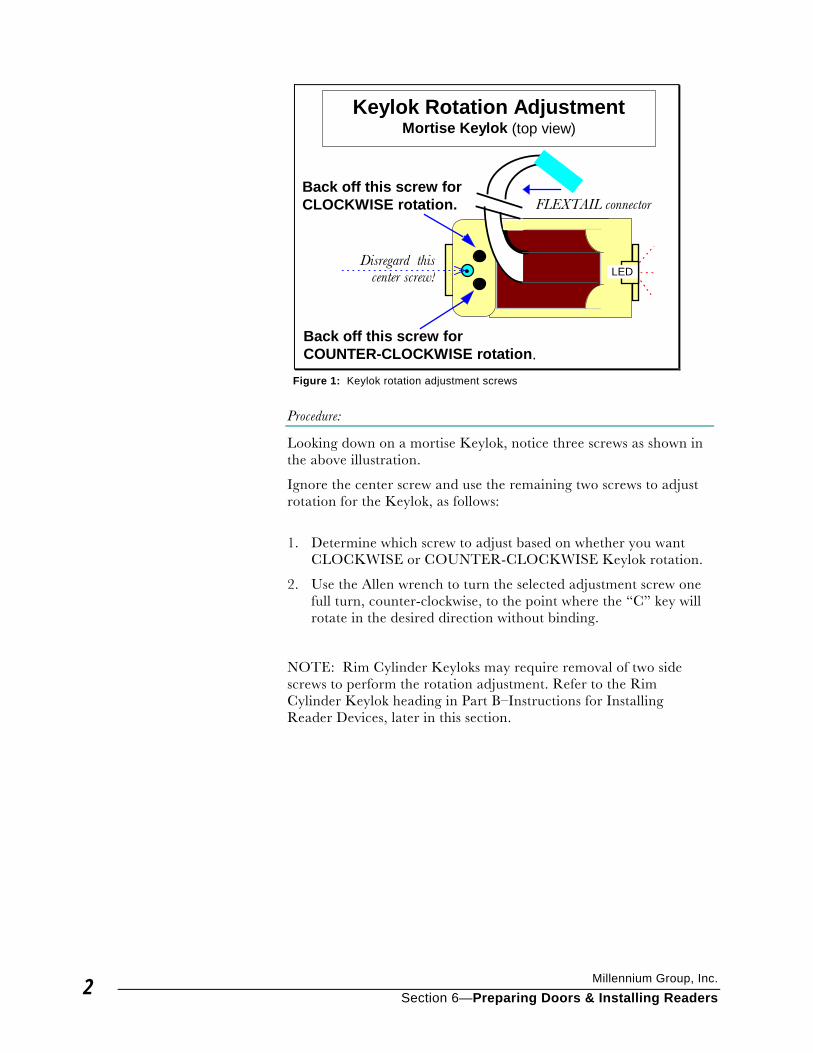
Millennium Group, Inc.
Section 6—Preparing Doors & Installing Readers 2
Procedure:
Looking down on a mortise Keylok, notice three screws as shown in the above illustration.
Ignore the center screw and use the remaining two screws to adjust rotation for the Keylok, as follows:
1. Determine which screw to adjust based on whether you want CLOCKWISE or COUNTER-CLOCKWISE Keylok rotation.
2. Use the Allen wrench to turn the selected adjustment screw one full turn, counter-clockwise, to the point where the “C” key will rotate in the desired direction without binding.
NOTE: Rim Cylinder Keyloks may require removal of two side screws to perform the rotation adjustment. Refer to the Rim Cylinder Keylok heading in Part B–Instructions for Installing Reader Devices, later in this section.
Disregard thiscenter screw!
Keylok Rotation AdjustmentMortise Keylok (top view)
Back off this screw forCLOCKWISE rotation.
Back off this screw forCOUNTER-CLOCKWISE rotation.
LED
FLEXTAIL connector
Figure 1: Keylok rotation adjustment screws
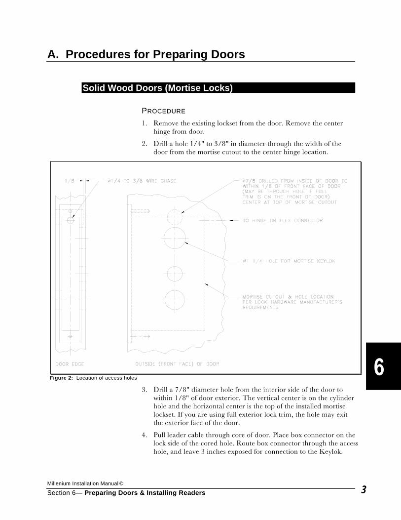
Millenium Installation Manual ©
Section 6— Preparing Doors & Installing Readers 3
A. Procedures for Preparing Doors
Solid Wood Doors (Mortise Locks) PROCEDURE 1. Remove the existing lockset from the door. Remove the center
hinge from door.
2. Drill a hole 1/4" to 3/8" in diameter through the width of the door from the mortise cutout to the center hinge location.
3. Drill a 7/8" diameter hole from the interior side of the door to within 1/8" of door exterior. The vertical center is on the cylinder hole and the horizontal center is the top of the installed mortise lockset. If you are using full exterior lock trim, the hole may exit the exterior face of the door.
4. Pull leader cable through core of door. Place box connector on the lock side of the cored hole. Route box connector through the access hole, and leave 3 inches exposed for connection to the Keylok.
Figure 2: Location of access holes
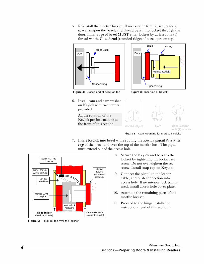
Millennium Group, Inc.
Section 6—Preparing Doors & Installing Readers 4
5. Re-install the mortise lockset. If no exterior trim is used, place a spacer ring on the bezel, and thread bezel into lockset through the door. Inner edge of bezel MUST enter lockset by at least one (1) thread width. Closed end (rounded ridge) of bezel goes on top.
6. Install cam and cam washer
on Keylok with two screws provided.
Adjust rotation of the Keylok per instructions at the front of this section.
7. Insert Keylok into bezel while routing the Keylok pigtail through the
top of the bezel and over the top of the mortise lock. The pigtail must extend out of the access hole.
8. Secure the Keylok and bezel to the lockset by tightening the lockset set screw. Do not over-tighten the set screw. Install snap cap on Keylok.
9. Connect the pigtail to the leader cable, and push connection into access hole. If no interior lock trim is used, install access hole cover plate.
10. Assemble the remaining parts of the mortise lockset.
11. Proceed to the hinge installation instructions (end of this section).
Door
Mortise Keylok
Bezel
Spacer Ring
Wires
Figure 3: Insertion of Keylok
DoorTop of Bezel
Spacer Ring
Figure 4: Closed end of bezel on top
Figure 5: Cam Mounting for Mortise Keyloks
Inside of Door(interior trim plate)
Outside of Door(exterior trim plate)
7/8” dia.drilled hole
1/4” to 3/8” dia.WIRE CHASE
Mortise CAMon Keylok
Mortise lockhardware
Keylok PIGTAILconnector
MortiseKeylok
(with bezelinserted)
Figure 6: Pigtail routes over the lockset
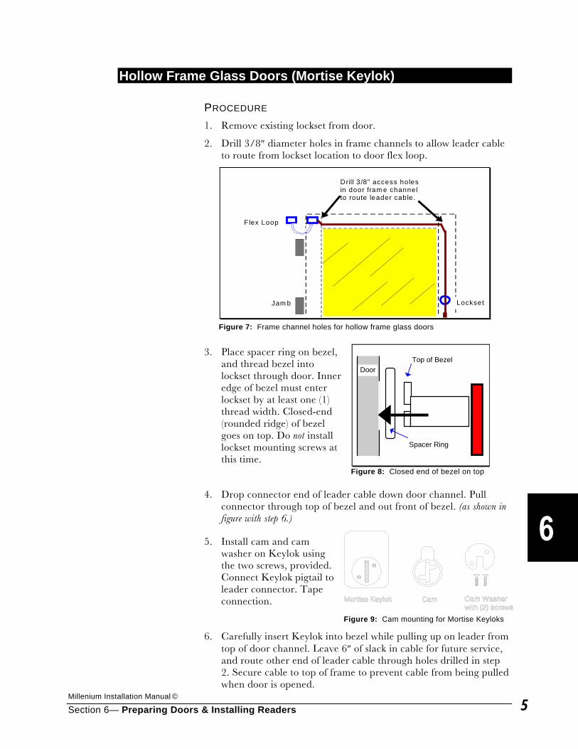
Millenium Installation Manual ©
Section 6— Preparing Doors & Installing Readers 5
Hollow Frame Glass Doors (Mortise Keylok) PROCEDURE 1. Remove existing lockset from door.
2. Drill 3/8″ diameter holes in frame channels to allow leader cable to route from lockset location to door flex loop.
3. Place spacer ring on bezel, and thread bezel into lockset through door. Inner edge of bezel must enter lockset by at least one (1) thread width. Closed-end (rounded ridge) of bezel goes on top. Do not install lockset mounting screws at this time.
4. Drop connector end of leader cable down door channel. Pull connector through top of bezel and out front of bezel. (as shown in figure with step 6.)
5. Install cam and cam washer on Keylok using the two screws, provided. Connect Keylok pigtail to leader connector. Tape connection.
6. Carefully insert Keylok into bezel while pulling up on leader from top of door channel. Leave 6″ of slack in cable for future service, and route other end of leader cable through holes drilled in step 2. Secure cable to top of frame to prevent cable from being pulled when door is opened.
Drill 3/8" access holesin door fram e channelto route leader cable.
Lockset
F lex Loop
Jam b
Figure 7: Frame channel holes for hollow frame glass doors
Top of BezelDoor
Spacer Ring
Figure 8: Closed end of bezel on top
Figure 9: Cam mounting for Mortise Keyloks
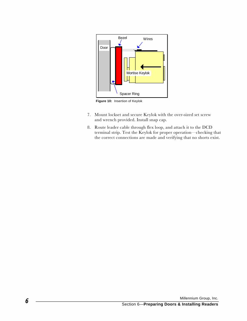
Millennium Group, Inc.
Section 6—Preparing Doors & Installing Readers 6
7. Mount lockset and secure Keylok with the over-sized set screw and wrench provided. Install snap cap.
8. Route leader cable through flex loop, and attach it to the DCD terminal strip. Test the Keylok for proper operation—checking that the correct connections are made and verifying that no shorts exist.
Door
Mortise Keylok
Bezel
Spacer Ring
Wires
Figure 10: Insertion of Keylok
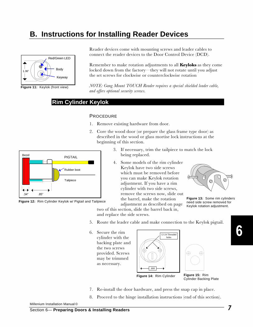
Millenium Installation Manual ©
Section 6— Preparing Doors & Installing Readers 7
B. Instructions for Installing Reader Devices Reader devices come with mounting screws and leader cables to connect the reader devices to the Door Control Device (DCD). Remember to make rotation adjustments to all Keyloks as they come locked down from the factory—they will not rotate until you adjust the set screws for clockwise or counterclockwise rotation NOTE: Gang Mount TOUCH Reader requires a special shielded leader cable, and offers optional security screws.
Rim Cylinder Keylok PROCEDURE 1. Remove existing hardware from door.
2. Core the wood door (or prepare the glass frame type door) as described in the wood or glass mortise lock instructions at the beginning of this section.
3. If necessary, trim the tailpiece to match the lock being replaced.
4. Some models of the rim cylinder Keylok have two side screws which must be removed before you can make Keylok rotation adjustment. If you have a rim cylinder with two side screws, remove the screws now, slide out the barrel, make the rotation adjustment as described on page
two of this section, slide the barrel back in, and replace the side screws.
5. Route the leader cable and make connection to the Keylok pigtail.
6. Secure the rim cylinder with the backing plate and the two screws provided. Screws may be trimmed as necessary.
7. Re-install the door hardware, and press the snap cap in place.
8. Proceed to the hinge installation instructions (end of this section).
1.36”
Keyway
Body
Red/Green LED
Figure 11: Keylok (front view)
.34” .85”
Tailpiece
PIGTAILBezel
Rubber boot
Figure 12: Rim Cylinder Keylok w/ Pigtail and Tailpiece
Figure 13: Some rim cylinders need side screw removed for Keylok rotation adjustment.
.800
12-24 Threadedholes
Figure 14: Rim Cylinder
Figure 15: Rim Cylinder Backing Plate
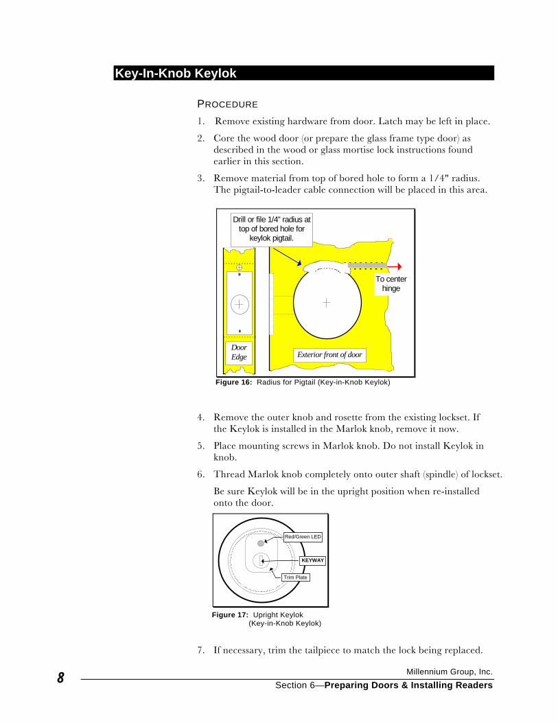
Millennium Group, Inc.
Section 6—Preparing Doors & Installing Readers 8
Key-In-Knob Keylok PROCEDURE 1. Remove existing hardware from door. Latch may be left in place.
2. Core the wood door (or prepare the glass frame type door) as described in the wood or glass mortise lock instructions found earlier in this section.
3. Remove material from top of bored hole to form a 1/4" radius. The pigtail-to-leader cable connection will be placed in this area.
4. Remove the outer knob and rosette from the existing lockset. If the Keylok is installed in the Marlok knob, remove it now.
5. Place mounting screws in Marlok knob. Do not install Keylok in knob.
6. Thread Marlok knob completely onto outer shaft (spindle) of lockset.
Be sure Keylok will be in the upright position when re-installed onto the door.
7. If necessary, trim the tailpiece to match the lock being replaced.
DoorEdge Exterior front of door
To centerhinge
Drill or file 1/4” radius attop of bored hole for
keylok pigtail.
Figure 16: Radius for Pigtail (Key-in-Knob Keylok)
KEYWAY
Trim Plate
Red/Green LED
Figure 17: Upright Keylok (Key-in-Knob Keylok)
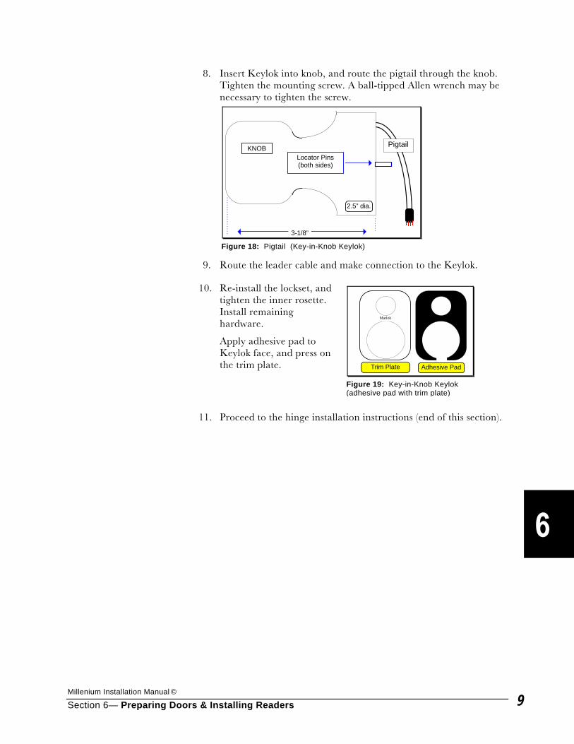
Millenium Installation Manual ©
Section 6— Preparing Doors & Installing Readers 9
8. Insert Keylok into knob, and route the pigtail through the knob. Tighten the mounting screw. A ball-tipped Allen wrench may be necessary to tighten the screw.
9. Route the leader cable and make connection to the Keylok.
10. Re-install the lockset, and tighten the inner rosette. Install remaining hardware.
Apply adhesive pad to Keylok face, and press on the trim plate.
11. Proceed to the hinge installation instructions (end of this section).
Pigtail
Locator Pins(both sides)
3-1/8”
KNOB
2.5” dia.
Figure 18: Pigtail (Key-in-Knob Keylok)
Marlok
Trim Plate Adhesive Pad
Figure 19: Key-in-Knob Keylok (adhesive pad with trim plate)
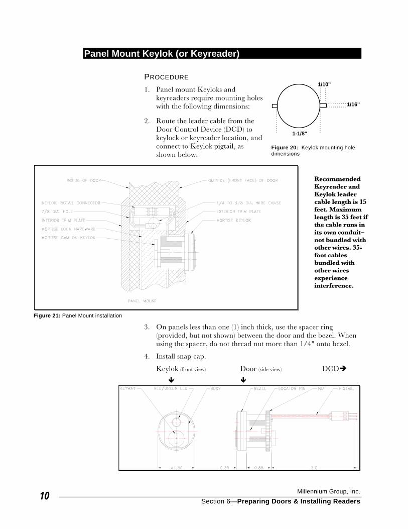
Millennium Group, Inc.
Section 6—Preparing Doors & Installing Readers 10
Panel Mount Keylok (or Keyreader) PROCEDURE 1. Panel mount Keyloks and
keyreaders require mounting holes with the following dimensions:
2. Route the leader cable from the
Door Control Device (DCD) to keylock or keyreader location, and connect to Keylok pigtail, as shown below.
Recommended Keyreader and Keylok leader cable length is 15 feet. Maximum length is 35 feet if the cable runs in its own conduit–not bundled with other wires. 35-foot cables bundled with other wires experience interference.
3. On panels less than one (1) inch thick, use the spacer ring (provided, but not shown) between the door and the bezel. When using the spacer, do not thread nut more than 1/4" onto bezel.
4. Install snap cap.
Keylok (front view) Door (side view) DCD�
� �
1/16"
1/10"
1-1/8"
Figure 20: Keylok mounting hole dimensions
Figure 21: Panel Mount installation
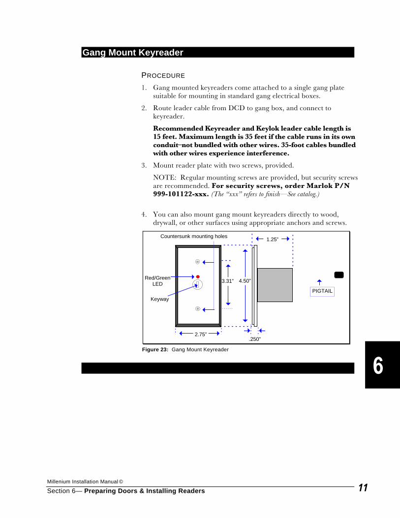
Millenium Installation Manual ©
Section 6— Preparing Doors & Installing Readers 11
Gang Mount Keyreader PROCEDURE 1. Gang mounted keyreaders come attached to a single gang plate
suitable for mounting in standard gang electrical boxes.
2. Route leader cable from DCD to gang box, and connect to keyreader.
Recommended Keyreader and Keylok leader cable length is 15 feet. Maximum length is 35 feet if the cable runs in its own conduit–not bundled with other wires. 35-foot cables bundled with other wires experience interference.
3. Mount reader plate with two screws, provided.
NOTE: Regular mounting screws are provided, but security screws are recommended. For security screws, order Marlok P/N 999-101122-xxx. (The “xxx” refers to finish—See catalog.)
4. You can also mount gang mount keyreaders directly to wood, drywall, or other surfaces using appropriate anchors and screws.
.250”
1.25”
4.50”3.31”
PIGTAIL
2.75”
Countersunk mounting holes
Keyway
Red/GreenLED
Figure 23: Gang Mount Keyreader
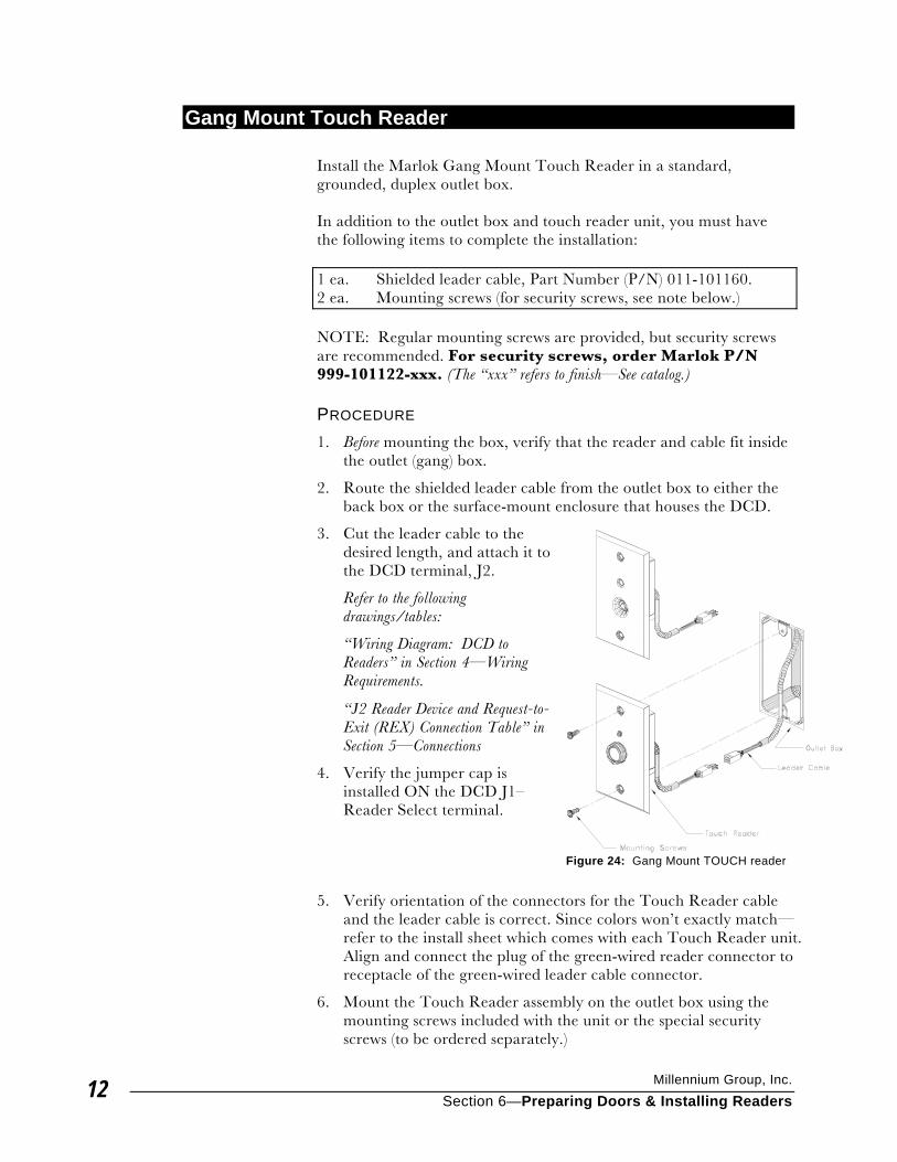
Millennium Group, Inc.
Section 6—Preparing Doors & Installing Readers 12
Gang Mount Touch Reader Install the Marlok Gang Mount Touch Reader in a standard, grounded, duplex outlet box. In addition to the outlet box and touch reader unit, you must have the following items to complete the installation: 1 ea. Shielded leader cable, Part Number (P/N) 011-101160. 2 ea. Mounting screws (for security screws, see note below.) NOTE: Regular mounting screws are provided, but security screws are recommended. For security screws, order Marlok P/N 999-101122-xxx. (The “xxx” refers to finish—See catalog.) PROCEDURE 1. Before mounting the box, verify that the reader and cable fit inside
the outlet (gang) box.
2. Route the shielded leader cable from the outlet box to either the back box or the surface-mount enclosure that houses the DCD.
3. Cut the leader cable to the desired length, and attach it to the DCD terminal, J2.
Refer to the following drawings/tables:
“Wiring Diagram: DCD to Readers” in Section 4—Wiring Requirements.
“J2 Reader Device and Request-to-Exit (REX) Connection Table” in Section 5—Connections
4. Verify the jumper cap is installed ON the DCD J1–Reader Select terminal.
5. Verify orientation of the connectors for the Touch Reader cable and the leader cable is correct. Since colors won’t exactly match—refer to the install sheet which comes with each Touch Reader unit. Align and connect the plug of the green-wired reader connector to receptacle of the green-wired leader cable connector.
6. Mount the Touch Reader assembly on the outlet box using the mounting screws included with the unit or the special security screws (to be ordered separately.)
Figure 24: Gang Mount TOUCH reader
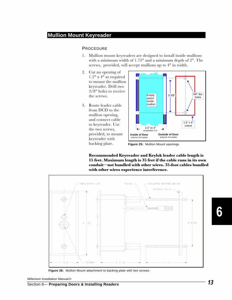
Millenium Installation Manual ©
Section 6— Preparing Doors & Installing Readers 13
Mullion Mount Keyreader PROCEDURE 1. Mullion mount keyreaders are designed to install inside mullions
with a minimum width of 1.75" and a minimum depth of 2". The screws, provided, will accept mullions up to 4" in width.
2. Cut an opening of 1.5" x 4" as required to mount the mullion keyreader. Drill two 3/8" holes to receive the screws.
3. Route leader cable from DCD to the mullion opening, and connect cable to keyreader. Use the two screws, provided, to mount keyreader with backing plate.
Recommended Keyreader and Keylok leader cable length is 15 feet. Maximum length is 35 feet if the cable runs in its own conduit—not bundled with other wires. 35-foot cables bundled with other wires experience interference.
1.5” x 4”cutout
3/8” dia.holes
3-3/8”Emptyspaceinsidemullion
2.5” to 4”acceptable O.D.
Inside of Door(interior trim plate)
Outside of Door(exterior trim plate)
Figure 25: Mullion Mount openings
Figure 26: Mullion Mount attachment to backing plate with two screws.

Millennium Group, Inc.
Section 6—Preparing Doors & Installing Readers 14
NOTE: For Wiegand-compatible Proximity, Mag Stripe, Biometric, Retinal, and any new technology readers, consult the detailed instructions provided with the reader.

Millenium Installation Manual ©
Section 6— Preparing Doors & Installing Readers 15
C. Hinge Installation
Conductive (“Electric”) Hinge FRAME PREPARATION PROCEDURE
1. Open door 90° or more, and remove screws from center hinge door and frame.
2. Drill 3/8" hole in the frame at location indicated. For wood or filled frames, remove sufficient material in frame to accommodate spliced wires and connectors.
Be sure to completely de-burr the holes.
3. Route leader cable from DCD to hinge location, and guide wires
from hole.
4. Use solderless connectors to attach leader cable leads to hinge leads. Match colors where possible. Note any non-matching colors for use on the “door preparation” side of the hinge, below.
5. Feed connected wires back into access hole, and install hinge to frame. DOOR PREPARATION PROCEDURE
1. Drill a 3/8" hole in the door at location indicated. For wood or filled frames, remove sufficient material in frame to accommodate spliced wires and connectors. Be sure to completely de-burr the hole.
2. Route leader cable from DCD to hinge location, and pull wires from hole.
3. Use solderless connectors to attach leader cable leads to hinge leads. Match colors where possible. Use the same non-matching colors you noted on the “Frame preparation” side of the hinge, above.
4. Feed connected wires back into access hole, and install hinge to door.
Figure 27: Typical Conductive Hinge with connective wires
FRAMEPreparation
DOORPreparation
3/8” accessholes forwiring.
Deburr holescompletely!
ConductiveHinge
Figure 28: Access holes for Conductive Hinge
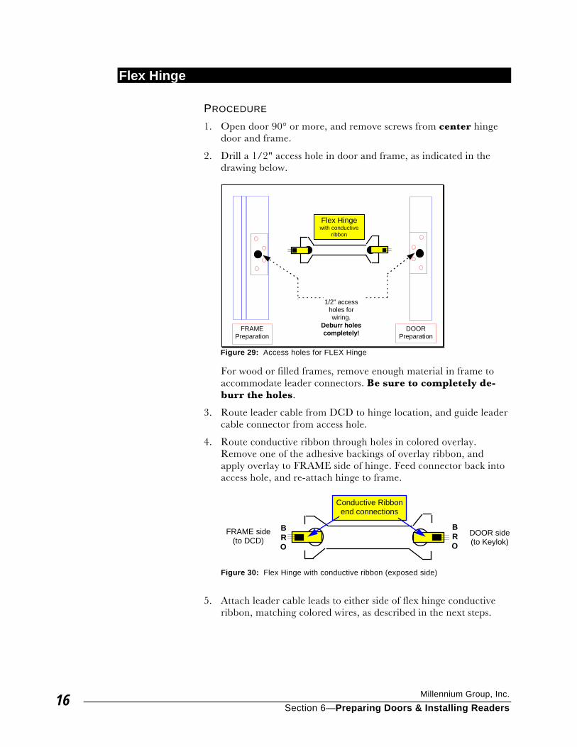
Millennium Group, Inc.
Section 6—Preparing Doors & Installing Readers 16
Flex Hinge PROCEDURE 1. Open door 90° or more, and remove screws from center hinge
door and frame.
2. Drill a 1/2" access hole in door and frame, as indicated in the drawing below.
For wood or filled frames, remove enough material in frame to accommodate leader connectors. Be sure to completely de-burr the holes.
3. Route leader cable from DCD to hinge location, and guide leader cable connector from access hole.
4. Route conductive ribbon through holes in colored overlay. Remove one of the adhesive backings of overlay ribbon, and apply overlay to FRAME side of hinge. Feed connector back into access hole, and re-attach hinge to frame.
5. Attach leader cable leads to either side of flex hinge conductive ribbon, matching colored wires, as described in the next steps.
FRAMEPreparation
DOORPreparation
1/2” accessholes forwiring.
Deburr holescompletely!
Flex Hingewith conductive
ribbon
Figure 29: Access holes for FLEX Hinge
Conductive Ribbonend connections
FRAME side(to DCD)
DOOR side(to Keylok)
BRO
BRO
Figure 30: Flex Hinge with conductive ribbon (exposed side)
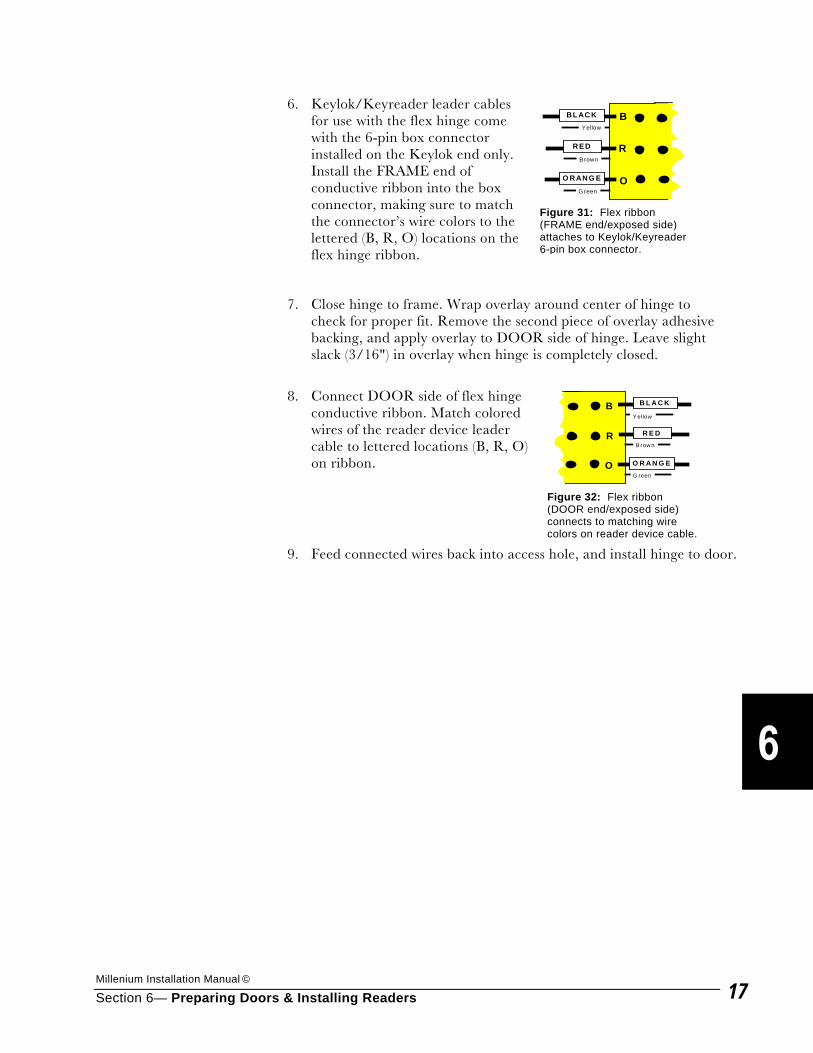
Millenium Installation Manual ©
Section 6— Preparing Doors & Installing Readers 17
6. Keylok/Keyreader leader cables for use with the flex hinge come with the 6-pin box connector installed on the Keylok end only. Install the FRAME end of conductive ribbon into the box connector, making sure to match the connector’s wire colors to the lettered (B, R, O) locations on the flex hinge ribbon.
7. Close hinge to frame. Wrap overlay around center of hinge to check for proper fit. Remove the second piece of overlay adhesive backing, and apply overlay to DOOR side of hinge. Leave slight slack (3/16") in overlay when hinge is completely closed.
8. Connect DOOR side of flex hinge conductive ribbon. Match colored wires of the reader device leader cable to lettered locations (B, R, O) on ribbon.
9. Feed connected wires back into access hole, and install hinge to door.
Yellow
Brown
G reen
B L AC K
R E D
O R AN G E
B
R
O
Figure 31: Flex ribbon (FRAME end/exposed side) attaches to Keylok/Keyreader 6-pin box connector.
Y ellow
B row n
G reen
B L A C K
R E D
O R A N G E
B
R
O
Figure 32: Flex ribbon (DOOR end/exposed side) connects to matching wire colors on reader device cable.

Millennium Group, Inc.
Section 6—Preparing Doors & Installing Readers 18
This Page Intentionally Left Blank
Millenium Installation Manual ©
Section 7— Glossary 1
Installation Glossary Includes terminology from Millenium and software, covered in the Operations Manuals. 1ST DCD Relay (See Strike relay in Millenium) 2ND DCD Relay. (See Shunt relay in Millenium) Access. Entry by permission to a controlled area of a facility. Access group. The combination of specific times (timezones) and certain access points (doors) that define a set of characteristics for each user. A user is assigned to an Access Group, and the access group’s defined characteristics determine the user’s access to controlled areas of the facility. Access point. See Door. Action. A task you perform by making a menu selection in Millenium software. A data box appears where you configure/program the system. Action key. Action keys speed up your work and make it easier. Action keys let you move around the screen, enter data without needing to type it. Certain Action keys only work in certain fields. When the bounce bar moves to a field, the symbol for the appropriate keys appears on the Action Key Bar at the bottom of the screen. Action letter. An uppercase letter found on each menu title and menu selection item. Typing the letter from the keyboard lets you open a menu or data box without using the bounce bar Alarm. The term is used two ways in Millenium systems: (1) A pre-programmed event that takes input from a device or tells the system operator of irregularities in the system. The input may trigger a relay on the DCD or RCD. The input always sends data (history) to the PC. (2) Alarm is also a type of History filter where the operator selects those access control history “actions” to be considered as alarms and displayed as such across the history section of the PC screen (Change filter.) History alarms can also be set to trigger an auditory sound at the main PC (Resident filter–ALARM.)
Alarm latch. An RCD mode in which a relay changes state (activates or deactivates) when triggered by a single event for a single device. The relay returns to its normal state when the reset of the event occurs. Alarm input point. Connections on a DCD (J6 terminal) to handle up to four (4) alarms in standard Millenium systems and up to seven (7) alarms in systems. Can be either sensor type: Normally Open or Normally Closed. Each alarm has a return connection for resets. Alarms 1-4 are supervised; Alarms 5-7 are unsupervised. In systems, alarm #7 offers a special “door ajar” feature. Alarms may be set to trigger a relay on a DCD or RCD. Always. A default timezone. Includes all times, all days, and all holidays. Use the Always timezone with a valid key when setting up normal operation of an electric strike. Antipassback. An access control protection option in which a user must exit from a site through a different door than the door that was used as the entrance. This condition prevents a user from “passing back” his key or card. Any valid alarm. A special relay mode, available for the 2ND DCD relay (Shunt relay) which activates for a selected period of time when any valid system alarm(s) are activated. Any user. A DCD relay mode in which a door activates for any user (valid or invalid) for a selected period of time—but only during the selected timezone. Auto activate. A DCD relay mode in which a door control device automatically activates at the beginning of a specified timezone and deactivates at the end of that timezone. Autologoff. An action found in the Logon menu. An operator chooses a period of time up to 99 minutes. At the end of that selected time period,
Millennium Group, Inc.
Section 7— Glossary 2
the system automatically logs off any logged on operator who has not used the keyboard during the period of time. Bounce bar. The highlighted bar or cursor that you use to choose actions from the selection menus and data boxes in Millenium software. Cable. (See Wire) A cable is more than one wire used together in one connection.
Cardreader. A device which senses special identification cards when they’re passed through, or inserted in a slot of the device. The cards have coded pattern of magnetic wires that generates an individual access number. The card validates a user. COM Port. Serial communications port on the PC (usually numbered 1-4). Used in Millenium systems to for TIUs and in systems for modem setups. Millenium software assigns COM port numbers in the set-up programs. In Millenium— “setupmil” program. In —“setupmp” program. Communications. Transfer of data between the PC computer and a control device. Communications take place through a Trunk Interface Unit (TIU). In , communications take place through Site Controller Units (SCUs) and can take place with or without modems. Computer. In this manual, refers to a personal computer (PC), 386 DX, 486 DX or better, on which Millenium software runs. Conductive Hinge. A type of door hinge sometimes known as “electric.” Leader cables from the Door Control Device feed through the hinge to provide an electrical connection for access control. Configure. To set up for operation in a particular way. The functional arrangement of PC hardware and software is often referred to as a configuration. When an operator programs data into Millenium software, the operator configures the access control system according to a specific access control plan. Connect to Sites: A field in the Options menu of “setupmp.” Select the communications configuration by which Site Controller will transmit
and receive data from access points. Options are: Direct, Trunk, Leased Line, Dial-Up, and three “Dial-Up with Local…” combinations. Console alarm. An action found in the Option menu. Any selected action in the Alarm filter causes the console alarm to sound, if enabled. DCD. Door Control Device Data. Access control activity detected at each device on the network and sent to the PC is referred to as data. Software programming sent to devices on the network are also referred to as data. Data box. The box that appears on the screen after you make a menu selection. You work with (program, configure) system data in a data box. Device. (1) In Millenium, a DCD, RCD, SCU, ECU, or ECD circuit board. (2) Can also refer to the door being controlled by a DCD or the alarm or auxiliary system being activated by an RCD. (3) An access control reader device refers to one of the many different types of devices that receive user input from a key/card, etc. to grant or deny access to a point in the facility. Device map. An action found in the Map menu. The open data box lists each site by:
• Site device • Status: “Online,” “Offline,” or “Unknown.” • Checksum (Level 1 Operator only)
Checksum indicates “Matched.” If a site is offline, or communication is interrupted between site and PC, “Function Unavailable” appears in Checksum field. Also, the results of the “Get Checksums” from the “Site” menu appear in Device map.
Dial-Up. One of the Site Controller configurations available under the Options menu (CONNECT TO SITES) in the “setupmp” function. Dial-Up represents a modem RS-232 connection between the Site Controller (J3 connector) and the PC’s COM port. Multiple remote sites can be connected through the Dial-Up option. Direct. One of the Site Controller configurations available under the Options menu (CONNECT TO SITES) in the “setupmp” function. Direct
Millenium Installation Manual ©
Section 7— Glossary 3
represents a direct (hard-wired), RS-232 cable connection between the Site Controller (J3 connector) and the PC’s COM port. (Maximum cable length is 50 feet. Greater distances require a TIU which expands distance capability to 5,000 feet total.) Door. The fundamental unit of an access control system. The first element that you add when configuring the access control system. You can have up to 100 doors per site. Often used to refer to a door control device–DCD. Door Control Device (DCD). A printed circuit board containing, among other things, terminals for inputs, two relays for direct outputs and data output to your computer where history is stored. Every reader device is connected to a DCD. ECU Elevator Control Units are optional circuit board devices in systems. Each Site Controller can handle up to four ECUs. Maximum number of doors an SCU can handle drops by 16 for each ECU installed. Each ECU has 16 relays to control up to 16 elevator floors. (Refer to a separate Elevator Installation Packet, P/N 047-101192.) (not investigated by UL)
Elevator. See ECU (Elevator Control Unit) (not investigated by UL) EOL Resistor. An End-of-Line (EOL) resistor is used in alarm systems to balance or “supervise” the wiring. The resistor looks for 1K Ohm of resistance across alarm inputs (first four alarms in DCD circuitry). If the resistance is not present, the alarm triggers. Each Door Control Device comes with four (4) resistors which can be installed. EPROM. Erasable, programmable memory chip on Millenium access control device circuit boards. EPROMs are labeled to identify the version of the firmware. Event. Similar to “data” (see “Data”), but causes a pre-determined action to happen. Events report alarms to Relay Control Devices and to the PC. Facility. See Site.
Fields. (1) The areas on a menu or data box where you interact with the system to manipulate data. Operators manipulate data by any of the following ways: adding, changing, deleting, or printing. (2) In “setupmp,” a Fields menu lets a Level 1 operator establish up to three custom fields for user data such as social security number. Filter. An action that sorts history as the history comes through the PC into user-defined groups of actions for display or reports. Under the History menu, an operator can filter history to view or print by user, by operator, by device (or in , by site.) (See also, Resident Filter.) Firmware. Refers to the circuit board devices (DCDs, RCD, etc.) at the heart of Millenium access control networks. Firmware issue levels determine what software features appear. (See Issue Level.) First event activation. An RCD relay mode where a relay activates at some time during the timezone after receiving the specified Event. Relay deactivates at the end of the timezone. Operator must specify the timezone, event(s), and device(s). First event release. An RCD relay mode where a relay deactivates at some time during the timezone after receiving the specified Event. Relay activates at the end of the timezone. Operator must specify the timezone, event(s), and device(s). First user auto activate. A relay mode in which a door control device activates when the first user with a valid key unlocks a door after the start of a selected period of time. Door remains unlocked until the selected time period expires. Flex Hinge. Type of door hinge using a flexible, conductive ribbon connection to Leader Cable. Leader Cable then connects to Door Control Device to provide electrical access control connection. Flex Loop. Type of cable conduit used in glass door installations to protect cable between the door and the door frame. Forgive Antipassback. Action that counters the Antipassback feature that was in effect at a selected door. The user is able to pass through that same “Entrance” door WITHOUT passing through the
Millennium Group, Inc.
Section 7— Glossary 4
designated “Exit” door. Exists under the Door menu. Function Switch ( ). A four-switch indicator on a Site Controller Unit circuit board which controls how the unit will function. Choices are: (1) Modem or Wired, (2) RS-232 or RS-485, (3) AC on or off, and (4) Pulse or Tone. Settings depend on the type of communication mode in effect as recorded in the CONNECT TO SITES field of “setupmp.” (Refer to Section 4–Connections under the Site Controller Unit in this installation manual.) Gang Mount. A term used to describe a regular electrical outlet box. Reader devices such as Touch readers and Keyreaders are often installed using a gang-mount box. Get Site History . Used only with Dialup communication modes. Found in Site selection menu. Use this action to see the list of sites. Use <Page Up/Down> and space bar to select sites for uploading transaction history to PC. Press <F10> to begin and complete data transfer. Note: This action does not update any door information. Ground. A term used to describe a conductor used as a common return for an electric circuit and as an arbitrary zero of potential. History. A record of the activities that make up the access control system. The PC collects all system data from the devices on the network and stores it on the hard disk. Holiday. One of the actions found in the Time menu. Holidays are one of the Days selections that you may use when adding a timezone. Ignore. Found on the “Alarm setup” data box in the software (Door menu.) The response entered in the IGNORE field tells you the timezone under which an alarm input is ignored. Invalid time. A condition where you use a key/card outside of its assigned times zone. Invalid user. A condition where a key/card is not in a door’s Door Control Device memory.
Issue Level. Sticker (∅, A, B, C, etc…) appears on the EPROM of circuit boards (DCDs, RCDs, etc.) in Millenium systems. Both the actual circuit boards and the level recorded in “setupmil” or “setupmp” determine whether or not the latest features appear in the software. Software features only reflect the oldest circuit board in the system. To take advantage of latest features, upgrade to the latest circuitry and update the setup records accordingly. Key. A Marlok key. Marlok keys are encoded at the factory. Each key is unique. Each key is non-erasable and non-reproducible. Marlok keys both appear and function like a regular key, and are used in Marlok Keyloks and Keyreaders. Keylok. A Marlok locking device. Has a rotating barrel that lets it fit standard conventional door hardware. The Keylok functions differently from conventional hardware because of the presence of an infrared (IR) light source and photocells to receive the IR beam. Keypad. A 12-key pad where pressure from the user's finger on each individual pad activates electronic circuitry and creates an input to the system. Keyreader. Describes two devices: (1) A Marlok access point reader device that contains an IR (infrared) light source and photocells to receive the IR beam. The keyreader differs from the Keylok in two major respects: (a.) barrel does not rotate, and (b.) keyreader connects to an external device, like an electric door strike, by means of a relay. (2) An RS-232 wedge-shaped device that attaches to the PC to read access codes from Marlok keys into the computer. LED. Abbreviation for light-emitting diode. (1) Millenium access control device circuit boards contain an LED which blinks slowly with power connection and blinks rapidly with communication connection between PC and the circuit board. (2) Marlok Keyloks/Keyreaders have an LED that shines red when powered and green when a valid key is inserted. If a valid key is used during an invalid timezone, the red LED blinks, but does not turn green.
Millenium Installation Manual ©
Section 7— Glossary 5
Leader Cable. Cable which connects reader devices to Millenium control devices (DCDs). Some reader devices require shielded cable and some distances between the circuit board and the reader also make shielded cable a requirement. Leased Line. A Lease Line acts a virtual wire between a Site Controller and the PC. Leased Line is one of the Site Controller CONNECT TO SITES modes under the Options menu in “setupmp.” Leased Line mode is an RS-232 real-time modem connection between the Site Controller (J3 terminal) and the PC’s COM port. In this mode, the PC can include an optional BOCA multi-port card to control communications for up to eight remote sites. Line Conditioner. A special circuit board termination or connection in the Power Supply. Provides load and bias voltage for communications lines. • Each Millenium system must have one Power
Supply with a factory-installed line conditioner. • Each Site Controller in a system must have
ONE Power Supply with a factory-installed line conditioner.
Line, Direct. Normally, hard wiring between the site controllers, usually within a single building. This type of connection places in a real-time communication mode. Line, Leased. Refers to remote connection via telephone lines or proprietary networks, both using some form of modem device. This type of connection places in a real-time communication mode. Line, Dialup mode. Uses normal telephone lines and standard modems. Used only when infrequent communication with remote sites is desired. Dial-up can be manual or automatically set to occur at pre-arranged times. Load. An act which allows an operator to work with or another application in real time. When you load Millenium software, the logon window appears, followed by the selection menu.
Logon. The act of logging on to the system to perform a task. Only Operators are authorized to logon. logOff. The act of logging off the system after finishing a task. When you logoff an on-line system, the screen remains visible and fills with access control history as it occurs. The opposite of Logon. LPT1. Line Printer port 1. The parallel communications port on the PC that usually connects the PC with the system printer. Map. The Map selection menu. Open data boxes from the menu consist of: Device, Site , Print device, and Print site maps . Network. All devices, including the PC, which make up the Millenium access control system. Never. A default timezone On-line. PC software is running and access control devices are installed, enabled, and communicating in real time—“as it happens.” (See Real Time, and see Site Poll ) Operator. An individual who is authorized to perform certain actions in the Millenium access control system software. has four (4) operator levels: • Level 4 operators view and print information
generated by the system. • Level 3 operators control the keys of users by
adding, changing, and deleting users as well as performing Level 4 tasks.
• Level 2 operators perform all Operator actions within the Logon menu as well as performing Level 3 tasks.
• Level 1 Operators perform “special mode” actions including “setupmp” along with all other actions available through .
Standard Millenium has three (3) operator levels, with Level 1 having access to “setupmil.” Override strike. Allows operator to temporarily override or interrupt the timezone and strike mode in a door with an electric strike. Exists under the Door menu.
Millennium Group, Inc.
Section 7— Glossary 6
Passback reject. Activation of anti-passback protection where after a user’s valid access is granted, it is temporarily disabled until the key/card is used to pass through a designated exit door or until a specified timezone ends. PC. In this manual, refers to the personal computer that runs the Millenium software. Pigtail. A short connector which runs between the readers (those devices which do not have terminals) and the leader cable. Polling. The interaction between the computer and devices on the system when PC sends a signal to and collects data from each device. Primary relay. See Strike relay (Millenium) or 1ST DCD Relay ( .) Print device map. Found in the “Map” selection menu. When opened, the data box prompts you for a printer. Scroll with <F4> or <F3> through the installed choices. Press <F10> to print a report containing the same information as “Device map.” Print site map . Found in “Map” selection menu in software. When opened, data box prompts you for a printer. Scroll with <F4> or <F3> through the installed choices. Press <F10> to print a report (with same information as “Site map”). Proximity. Cards with electronic circuitry that is embedded in plastic. Each card sends a signal to the cardreader device. The card need only be passed near the cardreader. Card reading devices can be installed behind glass, walls or other screening devices to be unobtrusive. Quick-Start checklist. Brief summary of programming steps for Millenium software. Located at the end of Section 2—Using the Setup Program(s) in the Operations manuals. RCD. optional Relay Control Device. Reader Select. A pin terminal on DCD circuit boards which identifies the type of reader device depending on whether a jumper cap is or is not placed on the processor (at the J1 location). Cap
must be OFF for Marlok Keyreaders and Marlok Keyloks. Cap is ON for all other readers. Real Time. Condition where data transmits to the PC computer on-line or as it happens. The alternative type of transmission is a reporting during a manual or automatic polling session where data is recorded after-the-fact. The Site Map and Device Map functions in Millenium software control and identify whether sites and devices are on-line, off-line, or disabled. In the “setupmp” function ( Options menu, CONNECT TO SITES), you select one of seven Site Controller Unit communication methods: Trunk, Direct, DialUp (plus three combinations), or Lease Line. Refresh site . Action appears in Site selection menu only when communication mode = DialUp. The open data box shows a list of sites needing data refreshing. Use <Page Up/Down> and space bar to select sites. Press <F10> to complete data transfer. Rejected user. Relay activates for a rejected user for a selected period of time—but only during selected timezone. Relay Control Device (RCD). An optional Millenium circuit board device consisting of 8 relays. Relays respond to events within timezones and control optional auxiliary devices. The first relay on the first RCD takes over polling in the event of a Site Controller or PC failure. systems handle up to 10 RCDs per site, and standard Millenium systems handle up to two RCDs. Remote unlock. An action found in the Door menu which allows the Level 1 operator to activate a strike and open a door from the console. The user whose key/card actually opened the door is considered a valid user under this condition. All operator levels can perform this action. Resident filter. Millenium software selection that determines which history records are displayed (SCREEN filter), printed (LPT filter), or cause alarms (ALARM filter) to sound at the PC. Also determines the timezone during which these actions will occur. Can use default filters of None, All, and Alarm, or a user-created filter (See also, Filters.) For example: if an operator only chooses the user-defined Resident SCREEN filter called
Millenium Installation Manual ©
Section 7— Glossary 7
“Operator Log,” only those history actions selected under the “Operator Log” user-defined filter display on the screen. Request to exit (R.E.X.). The activation of a request for exit from a Door Control Device. Opens locked doors for exit by using devices such as motion sensors, push buttons, or floor mats. Restore. Restore Millenium data or history files under the File menu in the software. Only Level 1 operators can perform a restore. Save. (1) In Millenium software, the F10 key saves data entered in a data box. (2) The act of copying data that exists on one disk to another disk. You make a copy of your data to keep it safe. SCU. Site Controller Unit. Setupmil. The limited-access set-up program in standard Millenium software where a Level 1 Operator establishes default settings to reflect installation requirements. Operator must run setupmil after initial installation and use the F10 key to save the setup. Setupmp . The limited-access set-up program in standard software where a Level 1 Operator establishes default settings to reflect installation requirements. Operator must run setupmp after initial installation and use the F10 key to save the setup in each of the menu selections after checking to see whether default settings meet individual requirements. Shield. A metal covering on a wire to prevent interference. Shielded cable comes with a ground wire. Communications wiring in Millenium systems calls for shielded cable. Some reader devices such as the TouchKey and Proximity readers require shielded cable. Readers located far from the DCD also require shielded cable. Shunt. To put across or bridge. In electrical terms, a conductor joining two points in an electrical circuit so as to form a parallel or alternative path through which all, or a portion of the current, may pass. An alarm shunt allows a user to come and go without causing an alarm input on an alarm system. For example, a motion detector might be shunted
(ignored) during normal business hours and only set to trigger at night. Shunt relay/2ND DCD Relay. Secondary of two relays on a DCD. In standard Millenium, second relay is called Shunt Relay. In this relay is called 2ND DCD Relay. Relay activates other devices after receiving an alarm input. Shunt relays activate or deactivate devices just as strike relays. The relay is normally used to shunt alarm circuits. This allows a person to come and go without causing an alarm input on an alarm system. Site. (Also known as a also known as a facility) The physical plant in which you install the access control system. Millenium systems handle single sites. In , you can have up to 1,000 sites — each under a Site Controller Unit. Site Controller Unit (SCU) . A device in the system that handles the polling and normal communication with DCDs, RCDs, and ECUs. Is the primary communication link between a site and the central PC. Through SCUs, software handles up to 1,000 remote sites with access control of up to 100 doors and up to 10 RCDs and up to four ECUs per Site Controller Unit.) Site Poll . Action in the Site data box in which you “Enable” a site (put the site “on-line”) and “Disable” a site (take it off line). “Disable” is the default. Site map . Found in the Map selection menu. Displays selected sites and their status. Status types include: Online, Offline and Disabled. Strike relay/1st DCD Relay. The primary one of two relays on a DCD. This relay activates an electric strike, or other locking device, from a DCD. The relay either activates or deactivate the electric device depending on the design of the system. When no electric strike requirement exists at a door, the relay can be used for other purposes. Source disk. A hard disk or a diskette on which data stored and sent to another disk. The receiving disk is called a target disk. “Supervisor.” Term describing...
Millennium Group, Inc.
Section 7— Glossary 8
• EOL (End-of-Line) resistor on an alarm input of a Door Control Device (DCD). The EOL resistor “supervises” or balances the line by looking for 1K Ohm of voltage. Any variance results in an alarm.
-or- • Relay #0 (terminals 1-3) on first Relay Control
Device (RCD) which assumes control of communications which normally occur between the PC and other devices in the Millenium network. The relay takes over or “supervises” whenever communications are lost from external causes. ( See “System Supervisor.”)
System. The combination of software, hardware and connecting devices such as relays and relay devices. System Supervisor. The name assigned to the relay mode of the No. 0 relay in the first Millenium RCD board. This relay remains energized while the relay board takes over the polling function of the computer whenever the computer is off line and not running the software. The System Supervisor relay de-energizes when the relay board polls a device, twice, with no response. This de-energized relay can set off an alarm and alert the system operator to the failure. Tamper alarm/Tamper alarm reset. Activation and reset of tamper switch. The DCD, RCD, or SCU cover on the enclosure holds switch in a deactivated state. When someone removes cover, the switch relays data to the computer where the event becomes history. Switch resets when the cover is secured and switch de-activates. If Tamper Alarm is set as an event through the software, the switch can trigger an alarm. Target disk. A hard disk or a diskette which stores data that is sent from another disk. The sending disk is called a source disk. Timezone. A preset period of time during which door controls or other devices allow an action to happen. Timezones include days of the week and holidays, as well as the time on a 24-hour clock. • To achieve timezone control of user access,
assign timezones to access groups. • To achieve timezone control of electric strike,
assign a relay mode to one of the DCD relays.
Timed activation. An RCD relay mode where a relay activates for a specific amount of time after receiving the Event. Activation cannot last more than 255 seconds. Timed release. An RCD relay mode where a relay deactivates for a specific amount of time after receiving the Event. You must specify Event(s) and Device(s). Activation cannot last more than 255 seconds. TouchKey. An electronic memory in a coin-size “can” or “chip” mounted to any convenient surface. When a user touches the key to a reader device, an input is sent to the system which may create a direct output to an electronic strike. Trunk. (1) Refers to the Trunk Interface Unit (TIU) which communicates between the PC and the Millenium system using a four-wire communications network. (2) TRUNK can also one of the Site Controller configurations available under the Options menu (CONNECT TO SITES) in the “setupmp” function. Trunk identifies a four-wire cable connection between the Site Controller (J4 connectors) and the PC’s COM port when a Trunk Interface Unit (TIU) is used in a configuration. Trunk Interface Unit (TIU). A small, modem-sized unit which takes serial output from the computer and transfers that output to the Millenium access control network. TIU communications use RS-485 connections. In applications, TIUs expand the maximum distance between the PC and a Site Controller from 50 feet to up to 5,000 feet (total). Unlock. A condition where a valid key/card unlocks a door during a valid Timezone. Doors can be set to automatically unlock at the beginning of a Timezone or with the first valid user during a specified Timezone. (See also, Remote unlock.) Update door (DCD). Action used to manually send data (users, timezones, etc.) to a DCD. Used when a DCD needs to be updated by a PC. (In “on-line” operations, the initial configuration would need to be updated to a door. Also, after a DCD has been off line for an extended period of time such as following a repair or replacement) you would perform an update.)
Millenium Installation Manual ©
Section 7— Glossary 9
Update relay (RCD). Action used to manually send data (users, timezones, etc.) to an RCD. Used when an RCD needs to be updated by a PC, as in the initial configuration. Update site. The action used to manually send a large amount of data to a site. Used when the PC needs to update the Site Controller Unit, as in the initial configuration. (Site menu) User. An individual who is accounted for by one of the Millenium systems. The user can be a valid user or an invalid user. Normally, a user is someone created in the software database (User menu) and assigned to an Access Group. In systems, users can also be added by access point and via linking files from Ilco System 800 and Solitaire System 3 stand-alone doors—setupmp.) Valid User. A user who is assigned to an access group and who is in the memory of one or more DCDs. The Valid User DCD relay mode activates a DCD relay for a valid user, for a selected period of time—but only during a specific timezone. Version. The version of Millenium or software currently being run appears in the lower left-hand corner of the screen. Wire. References to the wiring or cabling in Millenium systems include:
• 2-WIRE (OR 2-CONDUCTOR): A type of wiring comprised of two wires.
• PAIR (OR TWISTED PAIR): A “pair” refers to a twisted set of two wires.
• SHIELDED: A type of cable that is covered in metal to protect the wires from interference. Shielded cable includes a ground wire in the covering. Communications connections in Millenium systems require shielded cable. Certain types of reader devices (TouchKey, Proximity) always require shielded cable. Cardreaders and Keypad readers installed more than 50 feet from the DCD also require shielded cable.
• A CABLE is more than one wire bundled together. At the terminal block, the wires can be connected to individual terminals, or the
connection can be made through a pre-made box connector.
In addition to wire descriptions, wires can be identified by an “Alpha equivalent” reference number (Installation manual Section 4—Wiring Requirements).

Millennium Group, Inc.
Section 7— Glossary 1 0
This Page Intentionally Left Blank
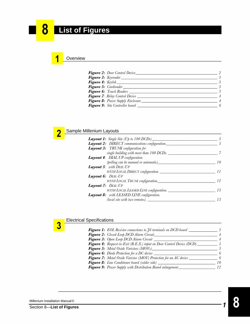
Millenium Installation Manual ©
Section 8—List of Figures 1
List of Figures
Overview
Figure 2: Door Control Device________________________________________ 2 Figure 3: Keyreader _______________________________________________ 3 Figure 4: Keylok _________________________________________________ 3 Figure 5: Cardreader ______________________________________________ 3 Figure 6: Touch Readers ___________________________________________ 3 Figure 7: Relay Control Device _______________________________________ 4 Figure 8: Power Supply Enclosure _____________________________________ 4 Figure 9: Site Controller board _______________________________________ 6
Sample Millenium Layouts
Layout 1: Single Site (Up to 100 DCDs)________________________________ 3 Layout 2: DIRECT communications configuration._________________________ 5 Layout 3: TRUNK configuration for single building with more than 100 DCDs. ________________________ 7 Layout 4: DIAL UP configuration (polling can be manual or automatic)____________________________ 10 Layout 5: with DIAL-UP WITH LOCAL DIRECT configuration. ___________________________ 11 Layout 6: DIAL-UP WITH LOCAL TRUNK configuration.____________________________ 12 Layout 7: DIAL-UP WITH LOCAL LEASED LINE configuration. _______________________ 13 Layout 8: with LEASED LINE configuration. (local site with two remotes). _________________________________ 15
Electrical Specifications Figure 1: EOL Resistor connections to J6 terminals on DCD board ______________ 3 Figure 2: Closed-Loop DCD Alarm Circuit_______________________________ 4 Figure 3: Open-Loop DCD Alarm Circuit _______________________________ 4 Figure 4: Request-to-Exit (R.E.X.) input on Door Control Device (DCD) __________ 5 Figure 5: Metal Oxide Varistors (MOVs)________________________________ 5 Figure 6: Diode Protection for a DC device _______________________________ 6 Figure 7: Metal Oxide Varistor (MOV) Protection for an AC device ______________ 6 Figure 8: Line Conditioner board (solder side) ____________________________ 10 Figure 9: Power Supply with Distribution Board enlargement __________________ 12
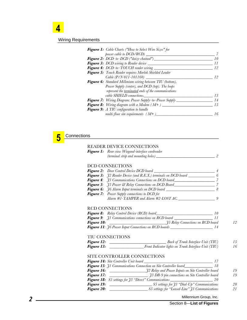
Millennium Group, Inc.
Section 8—List of Figures 2
Wiring Requirements Figure 1: Cable Charts ("How to Select Wire Sizes" for power cable to DCD/RCD) __________________________________ 7 Figure 2: DCD–to–DCD ("daisy-chained") _____________________________ 10 Figure 3: DCD wiring to Reader device ________________________________ 11 Figure 4: DCD–to–TOUCH reader wiring _____________________________ 12 Figure 5: Touch Reader requires Marlok Shielded Leader Cable (P/N 011-101160) _________________________________ 12 Figure 6: Standard Millenium wiring between TIU (bottom), Power Supply (center), and DCD (top). The loops represent the terminated ends of the communications cable SHIELD connections.__________________________________ 13 Figure 7: Wiring Diagram: Power Supply–to–Power Supply __________________ 14 Figure 8: Wiring diagram with a Modem ( M+ ) _________________________ 15 Figure 9: A TIU configuration to handle multi-floor site requirements ( M+ )____________________________ 16
Connections READER DEVICE CONNECTIONS Figure 1: Rear view Wiegand-interface cardreader (terminal strip and mounting holes) _____________________________ 2 DCD CONNECTIONS Figure 2: Door Control Device DCD board ______________________________ 4 Figure 3: J2 Reader Device (and R.E.X.) terminals on DCD board _____________ 6 Figure 4: J3 Communications Connections on DCD board____________________ 7 Figure 5: J5 Power & Relay Connections on DCD Board ____________________ 7 Figure 6: J6 Alarm Input terminals on DCD board ________________________ 8 Figure 7: Power Supply connections to DCD for Alarm #1-TAMPER and Alarm #2-LOST AC. __________________ 9 RCD CONNECTIONS Figure 8: Relay Control Device (RCD) board____________________________ 10 Figure 9: J1 Communications connections on RCD board ___________________ 11 Figure 10: ____________________________J5 Relay Connections on RCD board 12 Figure 11: J6 Power Input Connections on RCD boards _____________________ 14 TIU CONNECTIONS Figure 12: ____________________________ Back of Trunk Interface Unit (TIU) 15 Figure 13: _________________Front Indicator lights on Trunk Interface Unit (TIU) 16 SITE CONTROLLER CONNECTIONS Figure 14: Site Controller Unit board __________________________________ 17 Figure 15: J1 Communications Connection on Site Controller board______________ 18 Figure 16: __________________J2 Relay and Power Inputs on Site Controller board 19 Figure 17: ___________________ J3 DB-9 pin connections on Site Controller board 19 Figure 18: S5 settings for J3 “Direct” Communications _____________________ 20 Figure 19: _____________________ S5 settings for J3 “Dial-Up” Communications 20 Figure 20: ___________________S5 settings for “Leased-Line” J3 Communications 21
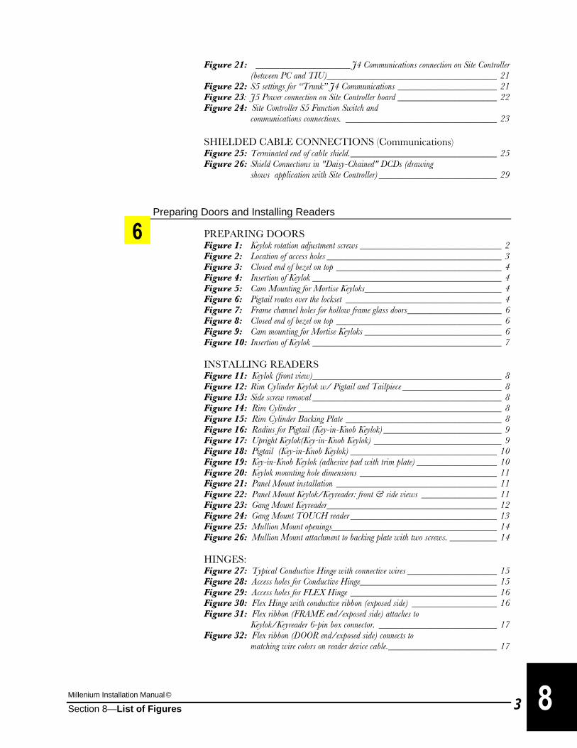
Millenium Installation Manual ©
Section 8—List of Figures 3
Figure 21: ____________________ J4 Communications connection on Site Controller (between PC and TIU)____________________________________ 21 Figure 22: S5 settings for “Trunk” J4 Communications _____________________ 21 Figure 23: J5 Power connection on Site Controller board _____________________ 22 Figure 24: Site Controller S5 Function Switch and communications connections. ________________________________ 23 SHIELDED CABLE CONNECTIONS (Communications) Figure 25: Terminated end of cable shield._______________________________ 25 Figure 26: Shield Connections in "Daisy-Chained" DCDs (drawing shows application with Site Controller) _________________________ 29
Preparing Doors and Installing Readers
PREPARING DOORS Figure 1: Keylok rotation adjustment screws ______________________________ 2 Figure 2: Location of access holes _____________________________________ 3 Figure 3: Closed end of bezel on top ___________________________________ 4 Figure 4: Insertion of Keylok ________________________________________ 4 Figure 5: Cam Mounting for Mortise Keyloks_____________________________ 4 Figure 6: Pigtail routes over the lockset _________________________________ 4 Figure 7: Frame channel holes for hollow frame glass doors____________________ 6 Figure 8: Closed end of bezel on top ___________________________________ 6 Figure 9: Cam mounting for Mortise Keyloks _____________________________ 6 Figure 10: Insertion of Keylok ________________________________________ 7 INSTALLING READERS Figure 11: Keylok (front view)________________________________________ 8 Figure 12: Rim Cylinder Keylok w/ Pigtail and Tailpiece _____________________ 8 Figure 13: Side screw removal ________________________________________ 8 Figure 14: Rim Cylinder ___________________________________________ 8 Figure 15: Rim Cylinder Backing Plate _________________________________ 8 Figure 16: Radius for Pigtail (Key-in-Knob Keylok) _________________________ 9 Figure 17: Upright Keylok(Key-in-Knob Keylok) ___________________________ 9 Figure 18: Pigtail (Key-in-Knob Keylok) _______________________________ 10 Figure 19: Key-in-Knob Keylok (adhesive pad with trim plate) _________________ 10 Figure 20: Keylok mounting hole dimensions _____________________________ 11 Figure 21: Panel Mount installation __________________________________ 11 Figure 22: Panel Mount Keylok/Keyreader: front & side views ________________ 11 Figure 23: Gang Mount Keyreader____________________________________ 12 Figure 24: Gang Mount TOUCH reader _______________________________ 13 Figure 25: Mullion Mount openings___________________________________ 14 Figure 26: Mullion Mount attachment to backing plate with two screws. __________ 14 HINGES: Figure 27: Typical Conductive Hinge with connective wires ___________________ 15 Figure 28: Access holes for Conductive Hinge_____________________________ 15 Figure 29: Access holes for FLEX Hinge _______________________________ 16 Figure 30: Flex Hinge with conductive ribbon (exposed side) __________________ 16 Figure 31: Flex ribbon (FRAME end/exposed side) attaches to Keylok/Keyreader 6-pin box connector. _________________________ 17 Figure 32: Flex ribbon (DOOR end/exposed side) connects to matching wire colors on reader device cable._______________________ 17