PRODUCTS CATALOG - ecommerce.cadel.ca · PRODUCTS CATALOG ENGINE HEATERS ... HOTSTART TPS tank...
58
P R O D U C T S C A T A L O G ENGINE HEATERS CONTROLS OIL HEATERS ACCESSORIES IMC-700
Transcript of PRODUCTS CATALOG - ecommerce.cadel.ca · PRODUCTS CATALOG ENGINE HEATERS ... HOTSTART TPS tank...

P R O D U C T S C A T A L O G
ENGINE HEATERS CONTROLS OIL HEATERS ACCESSORIES
IMC-700

PAGES 4 - 12 • Tank Style Coolant Heaters• Weathertight Design
PAGES 14 - 18 • Tank Style Coolant Heaters• Class 1, Group D for Hazardous Locations
PAGES 22 - 24 • HOTflow™ Heaters• CSM, CTM Series
PAGES 26 - 31 • Industrial Lube Oil Heaters • Lube Oil Heaters with Thermostat• Process Immersion Heaters with Fixed or
Adjustable Thermostat
PAGES 33 - 38 • Temperature Controls• Pressure Switch• Magnetic Contactors• Junction Boxes• Complete Control Systems
PAGES 40 - 42 • Battery Warming Pads and Accessories • Blanket Style Battery Warmers• Silicone Hot Pads
PAGES 44 - 55• In-block Direct Immersion Heaters• Electrical Cords for In-block Heaters• Thermocords• Flush Mount Kits and Accessories
Page 19Part number matrix for tank-style heaters
Page 20Tank-style
Page 53In-block
Page 56How to specify an engineheater and conversion charts
CUSTOM PRODUCTS
Call for information on:• Battery Chargers• Wiring Harnesses• Air Intake Heaters• APUs• Other Specialty Products
HEATER INSTALLATION
SE
CT
ION
1
4
3
2
5
6
T A B L E O F C O N T E N T S
7

P R O D U C T C A T A L O G
SE
CT
IO
N
1

HOTSTART TPS tank heaters are constructed from a durable, high-impact plastic. Every heater is assembledwith a built-in thermostat and 4–foot power cord.
EngineDisplacement
Model Number Volts Watts Phase AmpsThermostat Range
On Off
150cid
2.5L
TPS051GT8-000TPS051GT10-000TPS051GT12-000TPS052GT8-000TPS052GT10-000TPS052GT12-000
120120120240240240
500500500500500500
111111
4.24.24.22.12.12.1
80°F (27C) 100°F (38C)100°F (38C) 120°F (49C)120°F (49C) 140°F (60C)80°F (27C) 100°F (38C)
100°F (38C) 120°F (49C)120°F (49C) 140°F (60C)
350cid
5.7L
TPS101GT8-000TPS101GT10-000TPS101GT12-000TPS102GT8-000TPS102GT10-000TPS102GT12-000
120120120240240240
100010001000100010001000
111111
8.48.48.44.24.24.2
80°F (27C) 100°F (38C)100°F (38C) 120°F (49C)120°F (49C) 140°F (60C)80°F (27C) 100°F (38C)
100°F (38C) 120°F (49C)120°F (49C) 140°F (60C)
350 - 500cid
5.7 - 8.2L
TPS151GT8-000TPS151GT10-000TPS151GT12-000TPS152GT8-000TPS152GT10-000TPS152GT12-000
120120120240240240
150015001500150015001500
111111
12.512.512.56.36.36.3
80°F (27C) 100°F (38C)100°F (38C) 120°F (49C)120°F (49C) 140°F (60C)80°F (27C) 100°F (38C)
100°F (38C) 120°F (49C)120°F (49C) 140°F (60C)
500 - 700cid
8.2 - 11.5L
TPS181GT8-000TPS181GT10-000TPS181GT12-000TPS202GT8-000TPS202GT10-000TPS202GT12-000
120120120240240240
180018001800200020002000
111111
1515158.38.38.3
80°F (27C) 100°F (38C)100°F (38C) 120°F (49C)120°F (49C) 140°F (60C)80°F (27C) 100°F (38C)
100°F (38C) 120°F (49C)120°F (49C) 140°F (60C)
ModelNumber
Volts Watts
Replacement Parts
SensingUnit Element Tank Box Power
CordElementO-ring
TPS051GT8-000TPS051GT10-000TPS051GT12-000TPS052GT8-000TPS052GT10-000TPS052GT12-000
120120120240240240
500500500500500500
LSU-8LSU-10LSU-12LSU-8LSU-10LSU-12
REPS051T8REPS051T10REPS051T12REPS052T8REPS052T10REPS052T12
TPS-TTPS-TTPS-TTPS-TTPS-TTPS-T
CPS-1CPS-1CPS-1CPS-1CPS-1CPS-1
11P48UU11P48UU11P48UU21P48UU21P48UU21P48UU
TPS-BORTPS-BORTPS-BORTPS-BORTPS-BORTPS-BOR
TPS101GT8-000TPS101GT10-000TPS101GT12-000TPS102GT8-000TPS102GT10-000TPS102GT12-000
120120120240240240
100010001000100010001000
LSU-8LSU-10LSU-12LSU-8LSU-10LSU-12
REPS101T8REPS101T10REPS101T12REPS102T8REPS102T10REPS102T12
TPS-TTPS-TTPS-TTPS-TTPS-TTPS-T
CPS-1CPS-1CPS-1CPS-1CPS-1CPS-1
11P48UU11P48UU11P48UU21P48UU21P48UU21P48UU
TPS-BORTPS-BORTPS-BORTPS-BORTPS-BORTPS-BOR
TPS151GT8-000TPS151GT10-000TPS151GT12-000TPS152GT8-000TPS152GT10-000TPS152GT12-000
120120120240240240
150015001500150015001500
LSU-8LSU-10LSU-12LSU-8LSU-10LSU-12
REPS151T8REPS151T10REPS151T12REPS152T8REPS152T10REPS152T12
TPS-TTPS-TTPS-TTPS-TTPS-TTPS-T
CPS-1CPS-1CPS-1CPS-1CPS-1CPS-1
11P48UU11P48UU11P48UU21P48UU21P48UU21P48UU
TPS-BORTPS-BORTPS-BORTPS-BORTPS-BORTPS-BOR
TPS181GT8-000TPS181GT10-000TPS181GT12-000
120120120
180018001800
LSU-8LSU-10LSU-12
REPS181T8REPS181T10REPS181T12
TPS-TTPS-TTPS-T
CPS-1CPS-1CPS-1
12P16H48UU12P16H48UU12P16H48UU
TPS-BORTPS-BORTPS-BOR
TPS202GT8-000TPS202GT10-000TPS202GT12-000
240240240
200020002000
LSU-8LSU-10LSU-12
REPS202T8REPS202T10REPS202T12
TPS-TTPS-TTPS-T
CPS-1CPS-1CPS-1
21P48UU21P48UU21P48UU
TPS-BORTPS-BORTPS-BOR
For TPS Model heaters
Replacement Parts
Customer Support: (509) 536-8660 www.hotstart.com4
Small Tank Heaters
TPS SeriesSingle Phase
500-2000 Watts120V & 240V
ReplacementCord
ReplacementBox
ReplacementTank
Sensing Unit
ElementO-Ring
ReplacementElement
C US

In-LineAdjustableThermostat
RemoteThread-in
FixedTemperatureThermostat
6.7170.2mm
7.9200.6mm
OUTLET HOSEBARB .625 I.D.
INLETHOSEBARB
.625 I.D.
ThermostatWell
Power Y-cord
Adj. T-statAssembly 4.25
107.9mm
4.6116.8mm
1.538.1mm.25 (4X) Holes
For MountingBrackets
ADJUSTABLE 90-130°F (32-54°C)On differential – 20°F (-7°C)
In-line thermostat options:
EngineDisplacement
Model Number Volts Watts Phase AmpsThermostat Range
On Off
150cid
2.5L
TPS051GT12-001*TPS051GT12-A00TPS052GT12-001*TPS052GT12-A00
120120240240
500500500500
1111
4.24.22.12.1
100°F (38C) 120°F (49C)ADJUSTABLE
100°F (38C) 120°F (49C)ADJUSTABLE
350cid
5.7L
TPS101GT12-001*TPS101GT12-A00TPS102GT12-001*TPS102GT12-A00
120120240240
1000100010001000
1111
8.48.44.24.2
100°F (38C) 120°F (49C)ADJUSTABLE
100°F (38C) 120°F (49C)ADJUSTABLE
350 - 500cid
5.7 - 8.2L
TPS151GT12-001*TPS151GT12-A00TPS152GT12-001*TPS152GT12-A00
120120240240
1500150015001500
1111
12.512.56.36.3
100°F (38C) 120°F (49C)ADJUSTABLE
100°F (38C) 120°F (49C)ADJUSTABLE
500 - 700cid
8.2 - 11.5L
TPS181GT12-001*TPS181GT12-A00TPS202GT12-001*TPS202GT12-A00
120120240240
1800180020002000
1111
15158.38.3
100°F (38C) 120°F (49C)ADJUSTABLE
100°F (38C) 120°F (49C)ADJUSTABLE
* Remote thread-in fixed temperature thermostat
ModelNumber
Volts Watts
Replacement Parts
SensingUnit
ElementPowerY-cord
ThermostatWell
TPS051GT12-001*TPS051GT12-A00TPS052GT12-001*TPS052GT12-A00
120120240240
500500500500
LSU-10RSU90-130LSU-10RSU90-130
REPS051T12REPS051T12REPS052T12REPS052T12
TPS-YC1#
TPS-YC2#
TW2374-1#
TW2374-1#
TPS101GT12-001*TPS101GT12-A00TPS102GT12-001*TPS102GT12-A00
120120240240
1000100010001000
LSU-10RSU90-130LSU-10RSU90-130
REPS101T12REPS101T12REPS102T12REPS102T12
TPS-YC1#
TPS-YC2#
TW2374-1#
TW2374-1#
TPS151GT12-001*TPS151GT12-A00TPS152GT12-001*TPS152GT12-A00
120120240240
1500150015001500
LSU-10RSU90-130LSU-10RSU90-130
REPS151T12REPS151T12REPS152T12REPS152T12
TPS-YC1#
TPS-YC2#
TW2374-1#
TW2374-1#
TPS181GT12-001*TPS181GT12-A00TPS202GT12-001*TPS202GT12-A00
120120240240
1800180020002000
LSU-10RSU90-130LSU-10RSU90-130
REPS181T12REPS181T12REPS202T12REPS202T12
12P16H54S54X10UU#
TPS-YC2#
TW2374-1#
TW2374-1#
* Remote thread-in fixed temperature thermostat # Call Factory
For TPS Model heatersw/in-line adjustable andremote thread-in fixedthermostatSingle Phase
Common replacement partsfor all TPS Model heaters:— Tank— Box— Element O-ring
See table on p. 4
Replacement Parts
Customer Support: (509) 536-8660 www.hotstart.com 5
TPS Series w/in-lineadjustable and remotethread-in fixedthermostatSingle Phase
500-2000 Watts120V & 240V
Small Tank Heaters
C US
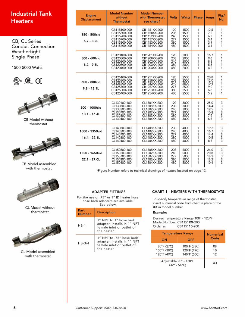
*Figure Number refers to technical drawings of heaters located on page 12.
EngineDisplacement
Model Numberwithout
Thermostat
Model Number with Thermostat
see chart 1Volts Watts Phase Amps
Fig.*No.
350 - 500cid
5.7 - 8.2L
CB115100-000CB115800-000CB115200-000CB115700-000CB115300-000CB115400-000
CB1151XX-200CB1158XX-200CB1152XX-200CB1157XX-200CB1153XX-200CB1154XX-200
120208240277380480
150015001500150015001500
111111
12.57.26.35.43.93.1
111111
500 - 600cid
8.2 - 9.8L
CB120100-000CB120800-000CB120200-000CB120300-000CB120400-000
CB1201XX-200CB1208XX-200CB1202XX-200CB1203XX-200CB1204XX-200
120208240380480
20002000200020002000
11111
16.79.68.35.34.2
11111
600 - 800cid
9.8 - 13.1L
CB125100-000CB125800-000CB125200-000CB125700-000CB125300-000CB125400-000
CB1251XX-200CB1258XX-200CB1252XX-200CB1257XX-200CB1253XX-200CB1254XX-200
120208240277380480
250025002500250025002500
111111
20.812.010.49.06.65.2
111111
800 - 1000cid
13.1 - 16.4L
CL130100-100CL130800-100CL130200-100CL130700-100CL130300-100CL130400-100
CL1301XX-200CL1308XX-200CL1302XX-200CL1307XX-200CL1303XX-200CL1304XX-200
120208240277380480
300030003000300030003000
111111
25.014.412.510.87.96.3
333333
1000 - 1350cid
16.4 - 22.1L
CL140800-100CL140200-100CL140700-100CL140300-100CL140400-100
CL1408XX-200CL1402XX-200CL1407XX-200CL1403XX-200CL1404XX-200
208240277380480
40004000400040004000
11111
19.216.714.410.58.3
33333
1350 - 1650cid
22.1 - 27.0L
CL150800-100CL150200-100CL150700-100CL150300-100CL150400-100
CL1508XX-200CL1502XX-200CL1507XX-200CL1503XX-200CL1504XX-200
208240277380480
50005000500050005000
11111
24.020.818.113.210.4
33333
ADAPTER FITTINGS
For the use of .75” or 1” ID heater hose,hose barb adapters are available.
See below.
PartNumber Description
HB-1
1” NPT to 1” hose barbadapter. Installs in 1” NPTfemale inlet or outlet ofthe heater.
HB-3/4
1” NPT to .75” hose barbadapter. Installs in 1” NPTfemale inlet or outlet ofthe heater.
CHART 1 - HEATERS WITH THERMOSTATS
To specify temperature range of thermostat,insert numerical code from chart in place of theXX in model number.
Example:
Desired Temperature Range 100° - 120°FModel Number: CB1151XX-200Order as: CB115110-200
Temperature Range NumericalCodeON OFF
80°F (27C)100°F (38C)120°F (49C)
100°F (38C)120°F (49C)140°F (60C)
081012
Adjustable 90° - 130°F(32° - 54°C)
A3
Customer Support: (509) 536-8660 www.hotstart.com6
Industrial TankHeaters
CB, CL SeriesConduit ConnectionWeathertightSingle Phase
1500-5000 Watts
CB Model without thermostat
CB Model assembledwith thermostat
CL Model assembled with thermostat
CL Model withoutthermostat
C US
Heaters with Thermostats
Temperature Range SensingUnit
ON OFF
80°F (27C)100°F (38C)120°F (49C)
100°F (38C)120°F (49C)140°F (60C)
FSU8FSU10FSU12
Adjustable 90° - 130°F(32°C - 54°C)
FSU90-130
Example:
Model Number: CB115110-200T-Stat Replacement: FSU10
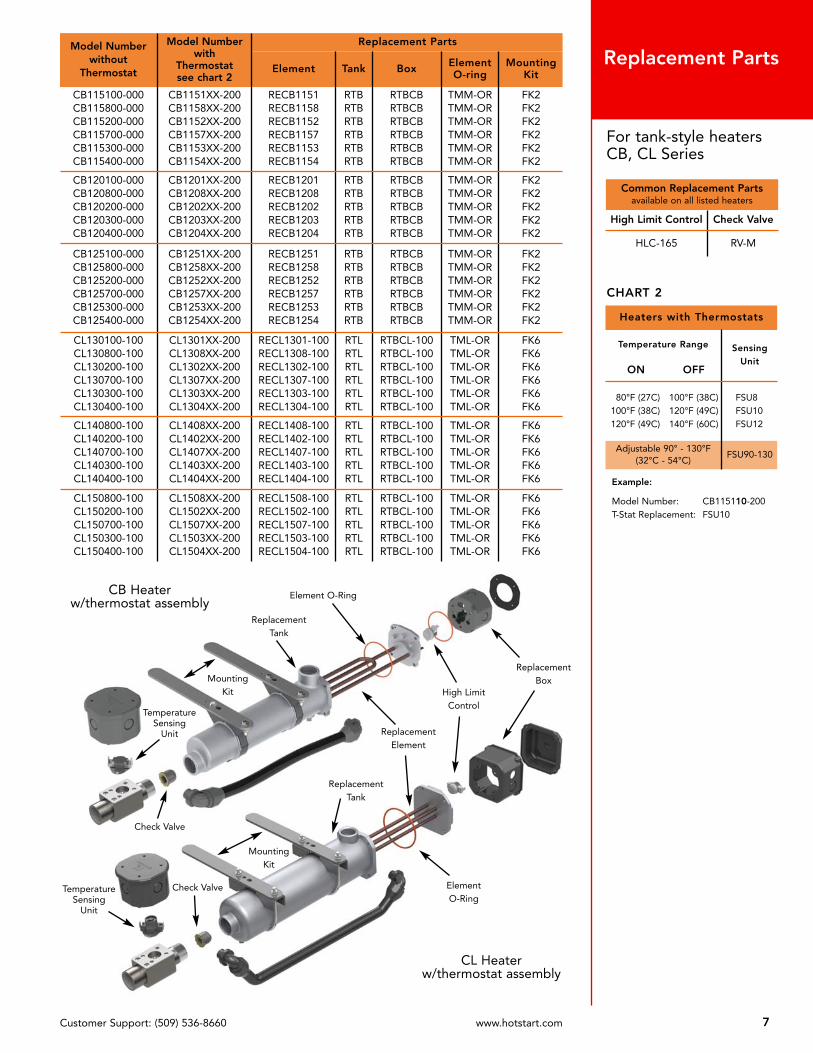
Model Numberwithout
Thermostat
Model Number with
Thermostatsee chart 2
Replacement Parts
Element Tank Box ElementO-ring
MountingKit
CB115100-000CB115800-000CB115200-000CB115700-000CB115300-000CB115400-000
CB1151XX-200CB1158XX-200CB1152XX-200CB1157XX-200CB1153XX-200CB1154XX-200
RECB1151RECB1158RECB1152RECB1157RECB1153RECB1154
RTBRTBRTBRTBRTBRTB
RTBCBRTBCBRTBCBRTBCBRTBCBRTBCB
TMM-ORTMM-ORTMM-ORTMM-ORTMM-ORTMM-OR
FK2FK2FK2FK2FK2FK2
CB120100-000CB120800-000CB120200-000CB120300-000CB120400-000
CB1201XX-200CB1208XX-200CB1202XX-200CB1203XX-200CB1204XX-200
RECB1201RECB1208RECB1202RECB1203RECB1204
RTBRTBRTBRTBRTB
RTBCBRTBCBRTBCBRTBCBRTBCB
TMM-ORTMM-ORTMM-ORTMM-ORTMM-OR
FK2FK2FK2FK2FK2
CB125100-000CB125800-000CB125200-000CB125700-000CB125300-000CB125400-000
CB1251XX-200CB1258XX-200CB1252XX-200CB1257XX-200CB1253XX-200CB1254XX-200
RECB1251RECB1258RECB1252RECB1257RECB1253RECB1254
RTBRTBRTBRTBRTBRTB
RTBCBRTBCBRTBCBRTBCBRTBCBRTBCB
TMM-ORTMM-ORTMM-ORTMM-ORTMM-ORTMM-OR
FK2FK2FK2FK2FK2FK2
CL130100-100CL130800-100CL130200-100CL130700-100CL130300-100CL130400-100
CL1301XX-200CL1308XX-200CL1302XX-200CL1307XX-200CL1303XX-200CL1304XX-200
RECL1301-100RECL1308-100RECL1302-100RECL1307-100RECL1303-100RECL1304-100
RTLRTLRTLRTLRTLRTL
RTBCL-100RTBCL-100RTBCL-100RTBCL-100RTBCL-100RTBCL-100
TML-ORTML-ORTML-ORTML-ORTML-ORTML-OR
FK6FK6FK6FK6FK6FK6
CL140800-100CL140200-100CL140700-100CL140300-100CL140400-100
CL1408XX-200CL1402XX-200CL1407XX-200CL1403XX-200CL1404XX-200
RECL1408-100RECL1402-100RECL1407-100RECL1403-100RECL1404-100
RTLRTLRTLRTLRTL
RTBCL-100RTBCL-100RTBCL-100RTBCL-100RTBCL-100
TML-ORTML-ORTML-ORTML-ORTML-OR
FK6FK6FK6FK6FK6
CL150800-100CL150200-100CL150700-100CL150300-100CL150400-100
CL1508XX-200CL1502XX-200CL1507XX-200CL1503XX-200CL1504XX-200
RECL1508-100RECL1502-100RECL1507-100RECL1503-100RECL1504-100
RTLRTLRTLRTLRTL
RTBCL-100RTBCL-100RTBCL-100RTBCL-100RTBCL-100
TML-ORTML-ORTML-ORTML-ORTML-OR
FK6FK6FK6FK6FK6
Common Replacement Partsavailable on all listed heaters
High Limit Control Check Valve
HLC-165 RV-M
CHART 2
ReplacementBox
Element O-Ring
ReplacementElement
ReplacementTank
MountingKit
ReplacementTank
ElementO-Ring
MountingKit
Check Valve
CL Heaterw/thermostat assembly
CB Heaterw/thermostat assembly
High LimitControl
TemperatureSensing
Unit
TemperatureSensing
Unit
Check Valve
For tank-style heatersCB, CL Series
Customer Support: (509) 536-8660 www.hotstart.com 7
Replacement Parts
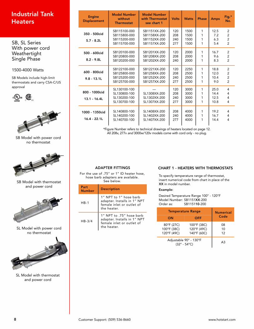
*Figure Number refers to technical drawings of heaters located on page 12.All 208v, 277v and 3000w/120v models come with cord only - no plug.
C US
SB Model with power cordno thermostat
SB Model with thermostatand power cord
SL Model with power cordno thermostat
SL Model with thermostatand power cord
EngineDisplacement
Model Number without
Thermostat
Model Number with Thermostat
see chart 1Volts Watts Phase Amps
Fig.*No.
350 - 500cid
5.7 - 8.2L
SB115100-000SB115800-000SB115200-000SB115700-000
SB1151XX-200SB1158XX-200SB1152XX-200SB1157XX-200
120208240277
1500150015001500
1111
12.57.26.35.4
2222
500 - 600cid
8.2 - 9.8L
SB120100-000SB120800-000SB120200-000
SB1201XX-200SB1208XX-200SB1202XX-200
120208240
200020002000
111
16.79.68.3
222
600 - 800cid
9.8 - 13.1L
SB122100-000SB125800-000SB125200-000SB125700-000
SB1221XX-200SB1258XX-200SB1252XX-200SB1257XX-200
120208240277
2250250025002500
1111
18.812.010.49.0
2222
800 - 1000cid
13.1 - 16.4L
SL130100-100SL130800-100SL130200-100SL130700-100
—SL1308XX-200SL1302XX-200SL1307XX-200
120208240277
3000300030003000
1111
25.014.412.510.8
4444
1000 - 1350cid
16.4 - 22.1L
SL140800-100SL140200-100SL140700-100
SL1408XX-200SL1402XX-200SL1407XX-200
208240277
400040004000
111
19.216.714.4
444
ADAPTER FITTINGS
For the use of .75” or 1” ID heater hose,hose barb adapters are available.
See below.
PartNumber Description
HB-1
1” NPT to 1” hose barbadapter. Installs in 1” NPTfemale inlet or outlet ofthe heater.
HB-3/4
1” NPT to .75” hose barbadapter. Installs in 1” NPTfemale inlet or outlet ofthe heater.
Customer Support: (509) 536-8660 www.hotstart.com8
Industrial TankHeaters
SB, SL SeriesWith power cordWeathertightSingle Phase
1500-4000 Watts
SB Models include high-limitthermostats and carry CSA-C/USapproval
CHART 1 - HEATERS WITH THERMOSTATS
To specify temperature range of thermostat,insert numerical code from chart in place of theXX in model number.
Example:
Desired Temperature Range 100° - 120°FModel Number: SB1151XX-200Order as: SB115110-200
Temperature Range NumericalCodeON OFF
80°F (27C)100°F (38C)120°F (49C)
100°F (38C)120°F (49C)140°F (60C)
081012
Adjustable 90° - 130°F(32° - 54°C)
A3

Heaters with Thermostats
Temperature Range SensingUnit
ON OFF
80°F (27C)100°F (38C)120°F (49C)
100°F (38C)120°F (49C)140°F (60C)
FSU8FSU10FSU12
Adjustable 90° - 130°F(32°C - 54°C)
FSU90-130
Example:
Model Number: SB115110-200T-Stat Replacement: FSU10
Common Replacement Partsavailable on all listed heaters
High Limit Control Check Valve
HLC-165 RV-M
CHART 2
Model Numberwithout
Thermostat
Model Number with
Thermostatsee chart 2
Replacement Parts
Element Tank Box PowerCord
ElementO-ring
MountingKit
SB115100-000SB115800-000SB115200-000SB115700-000
SB1151XX-200SB1158XX-200SB1152XX-200SB1157XX-200
RESB1151RESB1158RESB1152RESB1157
RTBRTBRTBRTB
RTBSBRTBSBRTBSBRTBSB
RHB-1-15RHB-WOPRHB-2-15RHB-WOP
TMM-ORTMM-ORTMM-ORTMM-OR
FK2FK2FK2FK2
SB120100-000SB120800-000SB120200-000
SB1201XX-200SB1208XX-200SB1202XX-200
RESB1201RESB1208RESB1202
RTBRTBRTB
RTBSBRTBSBRTBSB
RHB1-20RHB-WOPRHB-2-15
TMM-ORTMM-ORTMM-OR
FK2FK2FK2
SB122100-000SB125800-000SB125200-000SB125700-000
SB1221XX-200SB1258XX-200SB1252XX-200SB1257XX-200
RESB1221RECB1258RECB1252RECB1257
RTBRTBRTBRTB
RTBSBRTBSBRTBSBRTBSB
RHB-1-20RHB-WOPRHB-2-15RHB-WOP
TMM-ORTMM-ORTMM-ORTMM-OR
FK2FK2FK2FK2
SL130100-000SL130800-000SL130200-000SL130700-000
—SL1308XX-200SL1302XX-200SL1307XX-200
RECL1301RECL1308RECL1302RECL1307
RTLRTLRTLRTL
RTBCL-100RTBCL-100RTBCL-100RTBCL-100
N/ARHL-WOPRHL-2-15RHL-WOP
TML-ORTML-ORTML-ORTML-OR
FK6FK6FK6FK6
SL140800-000SL140200-000SL140700-000
SL1408XX-200SL1402XX-200SL1407XX-200
RECL1408RECL1402RECL1407
RTLRTLRTL
RTBCL-100RTBCL-100RTBCL-100
RHL-WOLRHL-2-20RHL-WOP
TML-ORTML-ORTML-OR
FK6FK6FK6
ReplacementBox
ElementO-Ring
ReplacementElement
ReplacementTank
MountingKit
ReplacementTank
ElementO-Ring
MountingKit
Check Valve
SL Heaterw/thermostat assembly
SB Heaterw/thermostat assembly
Check Valve
ReplacementElement
ReplacementBox
High LimitControl
High LimitControl
TemperatureSensing
Unit
TemperatureSensing
Unit
Customer Support: (509) 536-8660 www.hotstart.com 9
For tank-style heatersSB, SL Series
Replacement Parts

WL Model without thermostat
WL Model with thermostat
*Figure Number refers to technical drawings of heaters located on page 12.
Customer Support: (509) 536-8660 www.hotstart.com10
Industrial TankHeaters
WL SeriesWeathertightThree Phase
1500-5000 Watts
ADAPTER FITTINGS
For the use of .75” or 1” ID heater hose,hose barb adapters are available.
See below.
PartNumber Description
HB-1
1” NPT to 1” hose barbadapter. Installs in 1” NPTfemale inlet or outlet ofthe heater.
HB-3/4
1” NPT to .75” hose barbadapter. Installs in 1” NPTfemale inlet or outlet ofthe heater.
CHART 1 - HEATERS WITH THERMOSTATS
To specify temperature range of thermostat,insert numerical code from chart in place of theXX in model number.
Example:
Desired Temperature Range 100° - 120°FModel Number: WL3252XX-200Order as: WL325210-200
All 3 phaseheaters withthermostatmust use acontrol box
See ControlSystemspage 38
Temperature Range NumericalCode
ON OFF
80°F (27C)100°F (38C)120°F (49C)
100°F (38C)120°F (49C)140°F (60C)
081012
Adjustable 90° - 130°F(32° - 54°C)
A3
EngineDisplacement
Model Numberwithout
Thermostat
Model Number with Thermostat
see chart 1Volts Watts Phase Amps
Fig.*No.
600 - 800cid
9.8 - 13.1L
WL325800-000WL325200-000WL325A00-000WL325400-000WL325500-000
WL3258XX-200WL3252XX-200WL325AXX-200WL3254XX-200WL3255XX-200
208240400480575
25002500250025002500
33333
6.96.03.63.02.5
55555
1000 - 1350cid
16.4 - 22.1L
WL340800-000WL340200-000WL340A00-000WL340400-000WL340500-000
WL3408XX-200WL3402XX-200WL340AXX-200WL3404XX-200WL3405XX-200
208240400480575
40004000400040004000
33333
11.19.65.84.84.0
55555
1350 - 1650cid
22.1 - 27.0L
WL350800-000WL350200-000WL350A00-000WL350400-000WL350500-000
WL3508XX-200WL3502XX-200WL350AXX-200WL3504XX-200WL3505XX-200
208240400480575
50005000500050005000
33333
13.912.07.26.05.0
55555
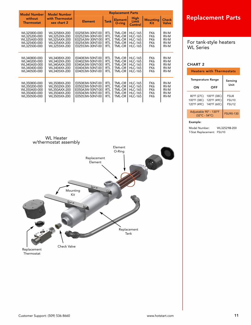
Model Numberwithout
Thermostat
Model Number with Thermostat
see chart 2
Replacement Parts
Element Tank ElementO-ring
HighLimit
Control
MountingKit
CheckValve
WL325800-000WL325200-000WL325A00-000WL325400-000WL325500-000
WL3258XX-200WL3252XX-200WL325AXX-200WL3254XX-200WL3255XX-200
E02583W-30NT-00E02523W-30NT-00E025A3W-30NT-00E02543W-30NT-00E02553W-30NT-00
RTLRTLRTLRTLRTL
TML-ORTML-ORTML-ORTML-ORTML-OR
HLC-165HLC-165HLC-165HLC-165HLC-165
FK6FK6FK6FK6FK6
RV-MRV-MRV-MRV-MRV-M
WL340800-000WL340200-000WL340A00-000WL340400-000WL340500-000
WL3408XX-200WL3402XX-200WL340AXX-200WL3404XX-200WL3405XX-200
E04083W-50NT-00E04023W-50NT-00E040A3W-50NT-00E04043W-50NT-00E04053W-50NT-00
RTLRTLRTLRTLRTL
TML-ORTML-ORTML-ORTML-ORTML-OR
HLC-165HLC-165HLC-165HLC-165HLC-165
FK6FK6FK6FK6FK6
RV-MRV-MRV-MRV-MRV-M
WL350800-000WL350200-000WL350A00-000WL350400-000WL350500-000
WL3508XX-200WL3502XX-200WL350AXX-200WL3504XX-200WL3505XX-200
E05083W-50NT-00E05023W-50NT-00E050A3W-50NT-00E05043W-50NT-00E05053W-50NT-00
RTLRTLRTLRTLRTL
TML-ORTML-ORTML-ORTML-ORTML-OR
HLC-165HLC-165HLC-165HLC-165HLC-165
FK6FK6FK6FK6FK6
RV-MRV-MRV-MRV-MRV-M
Customer Support: (509) 536-8660 www.hotstart.com 11
For tank-style heatersWL Series
Replacement Parts
Heaters with Thermostats
Temperature Range SensingUnit
ON OFF
80°F (27C)100°F (38C)120°F (49C)
100°F (38C)120°F (49C)140°F (60C)
FSU8FSU10FSU12
Adjustable 90° - 130°F(32°C - 54°C)
FSU90-130
Example:
Model Number: WL325210-200T-Stat Replacement: FSU10
CHART 2
ReplacementTank
MountingKit
ElementO-Ring
ReplacementThermostat
Check Valve
ReplacementElement
WL Heaterw/thermostat assembly

Customer Support: (509) 536-8660 www.hotstart.com
WL Style Heater without thermostat (pg. 10-11) FIGURE 5 WL Style Heater with thermostat (pg. 10-11)
CB Style Heater without thermostat (pg. 6-7) FIGURE 1 CB Style Heater with thermostat (pg. 6-7)
SB Style Heater without thermostat (pg. 8-9) FIGURE 2 SB Style Heater with thermostat (pg. 8-9)
CL Style Heater without thermostat (pg. 6-7) FIGURE 3 CL Style Heater with thermostat (pg. 6-7)
SL Style Heater without thermostat (pg. 8-9) FIGURE 4 SL Style Heater with thermostat (pg. 8-9)
Dimensional Drawings
12
inch, millimeter

P R O D U C T C A T A L O G
SE
CT
IO
N
2

EE Model assembled withthermostat
EE Model without thermostat
*Figure Number refers to technical drawings of heaters located on page 18.
EngineDisplacement
Model Numberwithout
Thermostat
Fig.*No.
Model Numberwith Thermostat
see chart 1
Fig.*No.
Volt Watt Phase Amp
500cidor less
8.2Lor less
EE115100-000EE115800-000EE115200-000EE115700-000EE115300-000EE115400-000EE115500-000
1111111
EE1151XX-000EE1158XX-000EE1152XX-000EE1157XX-000EE1153XX-000EE1154XX-000EE1155XX-000
2222222
120208240277380480575
1500150015001500150015001500
1111111
12.57.26.35.43.93.12.6
500 - 600cid
8.2 - 9.8L
EE120100-000EE120800-000EE120200-000EE120300-000EE120400-000EE120500-000
111111
EE1201XX-000EE1208XX-000EE1202XX-000EE1203XX-000EE1204XX-000EE1205XX-000
222222
120208240380480575
200020002000200020002000
111111
16.79.68.35.34.23.5
600 - 800cid
9.8 - 13.1L
EE125100-000EE125800-000EE125200-000EE125700-000EE125300-000EE125400-000EE125500-000
1111111
EE1251XX-000EE1258XX-000EE1252XX-000EE1257XX-000EE1253XX-000EE1254XX-000EE1255XX-000
2222222
120208240277380480575
2500250025002500250025002500
1111111
20.812.010.49.26.65.24.3
800 - 1000cid
13.1 - 16.4L
EE130100-000EE130800-000EE130200-000EE130700-000EE130300-000EE130400-000EE130500-000
1111111
EE1301XX-000EE1308XX-000EE1302XX-000EE1307XX-000EE1303XX-000EE1304XX-000EE1305XX-000
2222222
120208240277380480575
3000300030003000300030003000
1111111
25.014.412.510.87.96.35.2
1000 - 1350cid
16.4 - 22.1L
EE140800-000EE140200-000EE140700-000EE140300-000EE140400-000EE140500-000
111111
EE1408XX-000EE1402XX-000EE1407XX-000EE1403XX-000EE1404XX-000EE1405XX-000
222222
208240277380480575
400040004000400040004000
111111
19.216.714.410.58.37.0
1350 - 1650cid
22.1 - 27.0L
EE150800-000EE150200-000EE150700-000EE150300-000EE150400-000EE150500-000
111111
EE1508XX-000EE1502XX-000EE1507XX-000EE1503XX-000EE1504XX-000EE1505XX-000
222222
208240277380480575
500050005000500050005000
111111
24.020.818.113.210.48.7
Customer Support: (509) 536-8660 www.hotstart.com14
Industrial TankHeaters
EE SeriesHazardous LocationSingle Phase
1500-5000 Watts
ADAPTER FITTINGS
For the use of .75” or 1” ID heater hose,hose barb adapters are available.
See below.
PartNumber Description
HB-1
1” NPT to 1” hose barbadapter. Installs in 1” NPTfemale inlet or outlet ofthe heater.
HB-3/4
1” NPT to .75” hose barbadapter. Installs in 1” NPTfemale inlet or outlet ofthe heater.
CHART 1 - HEATERS WITH THERMOSTATS
To specify temperature range of thermostat,insert numerical code from chart in place of theXX in model number.
Example:
Desired Temperature Range 100° - 120°FModel Number: EE1302XX-000Order as: EE130210-000
3Ø heatersand heatersover 480vmust use acontrol box
See ControlSystemspage 38
Temperature Range NumericalCode
ON OFF
80°F (27C)
100°F (38C)
120°F (49C)
100°F (38C)
120°F (49C)
140°F (60C)
08
10
12

ModelNumber w/oThermostat
ModelNumber w/Thermostatsee chart 2
Replacement Parts
Element MI Cable Tank Flange FlangeO-ring
MountingKit
CheckValve
EE115100-000EE115800-000EE115200-000EE115700-000EE115300-000EE115400-000EE115500-000
EE1151XX-000EE1158XX-000EE1152XX-000EE1157XX-000EE1153XX-000EE1154XX-000EE1155XX-000
REEE1151REEE1158REEE1152REEE1157
E01531E-50NA-00E01541E-50NA-00E01551E-50NA-00
PRP104202-024PRP104202-024PRP104202-024PRP104202-024PRP104202-024PRP104202-024PRP104202-024
RTLRTLRTLRTLRTLRTLRTL
RF-LRF-LRF-LRF-LRF-LRF-LRF-L
TML-ORTML-ORTML-ORTML-ORTML-ORTML-ORTML-OR
FK6FK6FK6FK6FK6FK6FK6
RV-MRV-MRV-MRV-MRV-MRV-MRV-M
EE120100-000EE120800-000EE120200-000EE120300-000EE120400-000EE120500-000
EE1201XX-000EE1208XX-000EE1202XX-000EE1203XX-000EE1204XX-000EE1205XX-000
REEE1201REEE1208REEE1202
E02031E-50NA-00E02041E-50NA-00E02051E-50NA-00
PRP104202-024PRP104202-024PRP104202-024PRP104202-024PRP104202-024PRP104202-024
RTLRTLRTLRTLRTLRTL
RF-LRF-LRF-LRF-LRF-LRF-L
TML-ORTML-ORTML-ORTML-ORTML-ORTML-OR
FK6FK6FK6FK6FK6FK6
RV-MRV-MRV-MRV-MRV-MRV-M
EE125100-000EE125800-000EE125200-000EE125700-000EE125300-000EE125400-000EE125500-000
EE1251XX-000EE1258XX-000EE1252XX-000EE1257XX-000EE1253XX-000EE1254XX-000EE1255XX-000
REEE1251REEE1258REEE1252REEE1257
E02531E-C0NA-00E02541E-C0NA-00E02551E-C0NA-00
PRP104202-024PRP104202-024PRP104202-024PRP104202-024PRP104202-024PRP104202-024PRP104202-024
RTLRTLRTLRTLRTLRTLRTL
RF-LRF-LRF-LRF-LRF-LRF-LRF-L
TML-ORTML-ORTML-ORTML-ORTML-ORTML-ORTML-OR
FK6FK6FK6FK6FK6FK6FK6
RV-MRV-MRV-MRV-MRV-MRV-MRV-M
EE130100-000EE130800-000EE130200-000EE130700-000EE130300-000EE130400-000EE130500-000
EE1301XX-000EE1308XX-000EE1302XX-000EE1307XX-000EE1303XX-000EE1304XX-000EE1305XX-000
REEE1301REEE1308REEE1302REEE1307
E03031E-50NA-00E03041E-50NA-00E03051E-50NA-00
PRP104202-024PRP104202-024PRP104202-024PRP104202-024PRP104202-024PRP104202-024PRP104202-024
RTLRTLRTLRTLRTLRTLRTL
RF-LRF-LRF-LRF-LRF-LRF-LRF-L
TML-ORTML-ORTML-ORTML-ORTML-ORTML-ORTML-OR
FK6FK6FK6FK6FK6FK6FK6
RV-MRV-MRV-MRV-MRV-MRV-MRV-M
EE140800-000EE140200-000EE140700-000EE140300-000EE140400-000EE140500-000
EE1408XX-000EE1402XX-000EE1407XX-000EE1403XX-000EE1404XX-000EE1405XX-000
REEE1408REEE1402REEE1407
E04031E-50NA-00E04041E-50NA-00E04051E-50NA-00
PRP104202-024PRP104202-024PRP104202-024PRP104202-024PRP104202-024PRP104202-024
RTLRTLRTLRTLRTLRTL
RF-LRF-LRF-LRF-LRF-LRF-L
TML-ORTML-ORTML-ORTML-ORTML-ORTML-OR
FK6FK6FK6FK6FK6FK6
RV-MRV-MRV-MRV-MRV-MRV-M
EE150800-000EE150200-000EE150700-000EE150300-000EE150400-000EE150500-000
EE1508XX-000EE1502XX-000EE1507XX-000EE1503XX-000EE1504XX-000EE1505XX-000
E05081E-50NA-00E05021E-50NA-00E05071E-C0NA-00E05031E-C0NA-00E05041E-C0NA-00E05051E-C0NA-00
PRP104202-024PRP104202-024PRP104202-024PRP104202-024PRP104202-024PRP104202-024
RTLRTLRTLRTLRTLRTL
RF-LRF-LRF-LRF-LRF-LRF-L
TML-ORTML-ORTML-ORTML-ORTML-ORTML-OR
FK6FK6FK6FK6FK6FK6
RV-MRV-MRV-MRV-MRV-MRV-M
ReplacementTank
Mounting Kit
Flange &O-Ring
ReplacementThermostat
Check Valve
ReplacementElement
MI Cable
EE Heaterw/thermostat assembly
Customer Support: (509) 536-8660 www.hotstart.com 15
For tank-style heaters EE Series
Replacement Parts
Heaters with Thermostats
Temperature Range SensingUnit
ON OFF
80°F (27C)100°F (38C)120°F (49C)
100°F (38C)120°F (49C)140°F (60C)
RSU8RSU10RSU12
Example:
Model Number: EE130210-000T-Stat Replacement: FSU10
CHART 2
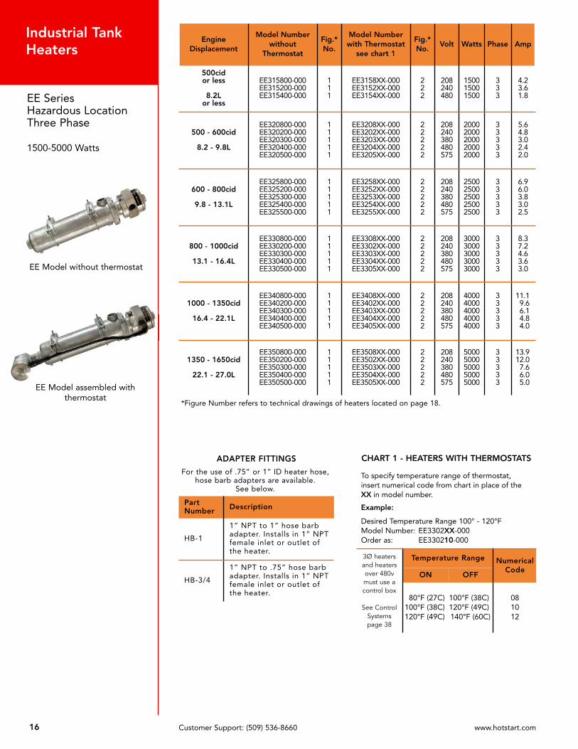
*Figure Number refers to technical drawings of heaters located on page 18.
EngineDisplacement
Model Numberwithout
Thermostat
Fig.*No.
Model Number with Thermostat
see chart 1
Fig.*No.
Volt Watts Phase Amp
500cidor less
8.2Lor less
EE315800-000EE315200-000EE315400-000
111
EE3158XX-000EE3152XX-000EE3154XX-000
222
208240480
150015001500
333
4.23.61.8
500 - 600cid
8.2 - 9.8L
EE320800-000EE320200-000EE320300-000EE320400-000EE320500-000
11111
EE3208XX-000EE3202XX-000EE3203XX-000EE3204XX-000EE3205XX-000
22222
208240380480575
20002000200020002000
33333
5.64.83.02.42.0
600 - 800cid
9.8 - 13.1L
EE325800-000EE325200-000EE325300-000EE325400-000EE325500-000
11111
EE3258XX-000EE3252XX-000EE3253XX-000EE3254XX-000EE3255XX-000
22222
208240380480575
25002500250025002500
33333
6.96.03.83.02.5
800 - 1000cid
13.1 - 16.4L
EE330800-000EE330200-000EE330300-000EE330400-000EE330500-000
11111
EE3308XX-000EE3302XX-000EE3303XX-000EE3304XX-000EE3305XX-000
22222
208240380480575
30003000300030003000
33333
8.37.24.63.63.0
1000 - 1350cid
16.4 - 22.1L
EE340800-000EE340200-000EE340300-000EE340400-000EE340500-000
11111
EE3408XX-000EE3402XX-000EE3403XX-000EE3404XX-000EE3405XX-000
22222
208240380480575
40004000400040004000
33333
11.19.66.14.84.0
1350 - 1650cid
22.1 - 27.0L
EE350800-000EE350200-000EE350300-000EE350400-000EE350500-000
11111
EE3508XX-000EE3502XX-000EE3503XX-000EE3504XX-000EE3505XX-000
22222
208240380480575
50005000500050005000
33333
13.912.07.66.05.0
Customer Support: (509) 536-8660 www.hotstart.com16
Industrial TankHeaters
EE SeriesHazardous LocationThree Phase
1500-5000 Watts
EE Model assembled withthermostat
EE Model without thermostat
ADAPTER FITTINGS
For the use of .75” or 1” ID heater hose,hose barb adapters are available.
See below.
PartNumber Description
HB-1
1” NPT to 1” hose barbadapter. Installs in 1” NPTfemale inlet or outlet ofthe heater.
HB-3/4
1” NPT to .75” hose barbadapter. Installs in 1” NPTfemale inlet or outlet ofthe heater.
CHART 1 - HEATERS WITH THERMOSTATS
To specify temperature range of thermostat,insert numerical code from chart in place of theXX in model number.
Example:
Desired Temperature Range 100° - 120°FModel Number: EE3302XX-000Order as: EE330210-000
3Ø heatersand heatersover 480vmust use acontrol box
See ControlSystemspage 38
Temperature Range NumericalCode
ON OFF
80°F (27C)100°F (38C)120°F (49C)
100°F (38C)120°F (49C)140°F (60C)
081012
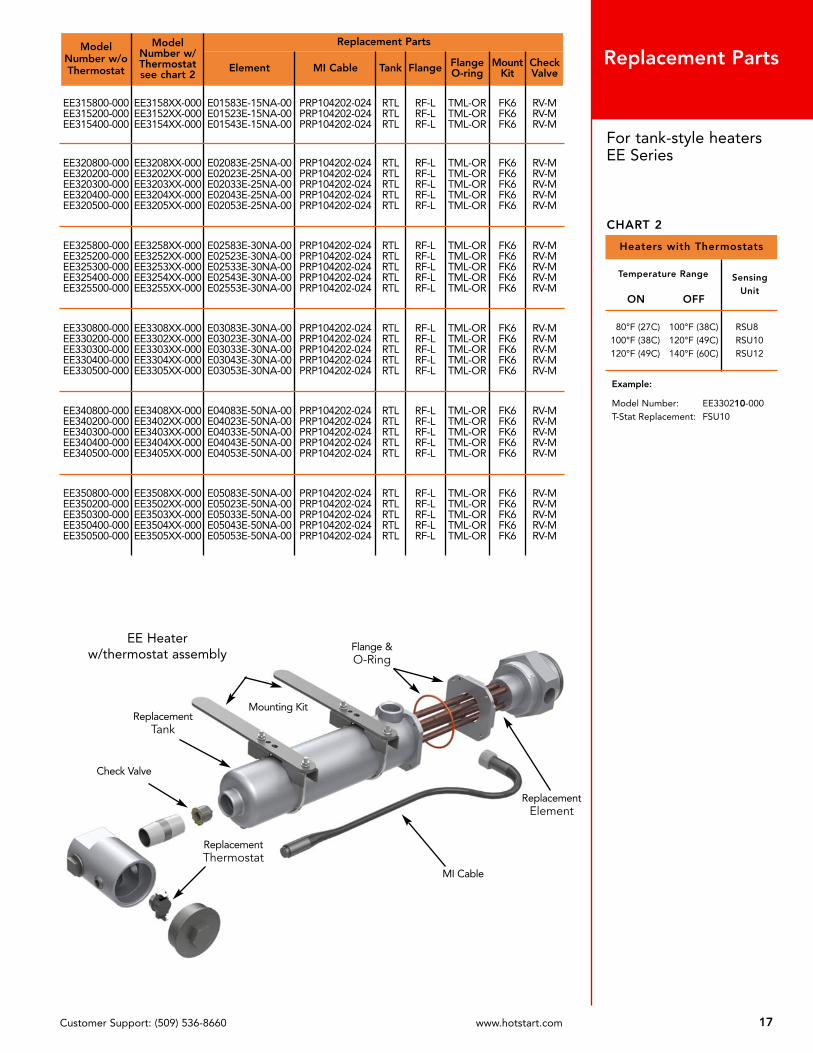
ModelNumber w/oThermostat
ModelNumber w/Thermostatsee chart 2
Replacement Parts
Element MI Cable Tank Flange FlangeO-ring
MountKit
CheckValve
EE315800-000EE315200-000EE315400-000
EE3158XX-000EE3152XX-000EE3154XX-000
E01583E-15NA-00E01523E-15NA-00E01543E-15NA-00
PRP104202-024PRP104202-024PRP104202-024
RTLRTLRTL
RF-LRF-LRF-L
TML-ORTML-ORTML-OR
FK6FK6FK6
RV-MRV-MRV-M
EE320800-000EE320200-000EE320300-000EE320400-000EE320500-000
EE3208XX-000EE3202XX-000EE3203XX-000EE3204XX-000EE3205XX-000
E02083E-25NA-00E02023E-25NA-00E02033E-25NA-00E02043E-25NA-00E02053E-25NA-00
PRP104202-024PRP104202-024PRP104202-024PRP104202-024PRP104202-024
RTLRTLRTLRTLRTL
RF-LRF-LRF-LRF-LRF-L
TML-ORTML-ORTML-ORTML-ORTML-OR
FK6FK6FK6FK6FK6
RV-MRV-MRV-MRV-MRV-M
EE325800-000EE325200-000EE325300-000EE325400-000EE325500-000
EE3258XX-000EE3252XX-000EE3253XX-000EE3254XX-000EE3255XX-000
E02583E-30NA-00E02523E-30NA-00E02533E-30NA-00E02543E-30NA-00E02553E-30NA-00
PRP104202-024PRP104202-024PRP104202-024PRP104202-024PRP104202-024
RTLRTLRTLRTLRTL
RF-LRF-LRF-LRF-LRF-L
TML-ORTML-ORTML-ORTML-ORTML-OR
FK6FK6FK6FK6FK6
RV-MRV-MRV-MRV-MRV-M
EE330800-000EE330200-000EE330300-000EE330400-000EE330500-000
EE3308XX-000EE3302XX-000EE3303XX-000EE3304XX-000EE3305XX-000
E03083E-30NA-00E03023E-30NA-00E03033E-30NA-00E03043E-30NA-00E03053E-30NA-00
PRP104202-024PRP104202-024PRP104202-024PRP104202-024PRP104202-024
RTLRTLRTLRTLRTL
RF-LRF-LRF-LRF-LRF-L
TML-ORTML-ORTML-ORTML-ORTML-OR
FK6FK6FK6FK6FK6
RV-MRV-MRV-MRV-MRV-M
EE340800-000EE340200-000EE340300-000EE340400-000EE340500-000
EE3408XX-000EE3402XX-000EE3403XX-000EE3404XX-000EE3405XX-000
E04083E-50NA-00E04023E-50NA-00E04033E-50NA-00E04043E-50NA-00E04053E-50NA-00
PRP104202-024PRP104202-024PRP104202-024PRP104202-024PRP104202-024
RTLRTLRTLRTLRTL
RF-LRF-LRF-LRF-LRF-L
TML-ORTML-ORTML-ORTML-ORTML-OR
FK6FK6FK6FK6FK6
RV-MRV-MRV-MRV-MRV-M
EE350800-000EE350200-000EE350300-000EE350400-000EE350500-000
EE3508XX-000EE3502XX-000EE3503XX-000EE3504XX-000EE3505XX-000
E05083E-50NA-00E05023E-50NA-00E05033E-50NA-00E05043E-50NA-00E05053E-50NA-00
PRP104202-024PRP104202-024PRP104202-024PRP104202-024PRP104202-024
RTLRTLRTLRTLRTL
RF-LRF-LRF-LRF-LRF-L
TML-ORTML-ORTML-ORTML-ORTML-OR
FK6FK6FK6FK6FK6
RV-MRV-MRV-MRV-MRV-M
Customer Support: (509) 536-8660 www.hotstart.com 17
For tank-style heaters EE Series
Replacement Parts
Heaters with Thermostats
Temperature Range SensingUnit
ON OFF
80°F (27C)100°F (38C)120°F (49C)
100°F (38C)120°F (49C)140°F (60C)
RSU8RSU10RSU12
Example:
Model Number: EE330210-000T-Stat Replacement: FSU10
CHART 2
ReplacementTank
Mounting Kit
Flange &O-Ring
ReplacementThermostat
Check Valve
ReplacementElement
MI Cable
EE Heaterw/thermostat assembly

EE heater without thermostat (pg. 14 and 16)
EE heater with thermostat (pg. 14 and 16)
Customer Support: (509) 536-8660 www.hotstart.com18
Dimensional Drawingsinch, millimeter

19Customer Support: (509) 536-8660 www.hotstart.com
Typical 11-digit part number
Enclosure Type Tank Phase Watts Volts Thermostat Options
C B 1 15 1 XX —000
Part Numbering SystemEach letter or number in the HOTSTART tank-style heater part number represents a piece of information toaccurately provide you with the description and composition of your HOTSTART heater.
First Digit - [ENCLOSURE TYPE] 1 letterTYPE: SSingle phase onlyMaximum volts and watts: 277v, 4000wStandard heater cord in cover — watertight
TYPE: WThree phase onlyMaximum volts and watts: 575v, 5000wConduit connection — watertight
TYPE: CSingle phase onlyMaximum volts and watts: 575v, 5000wConduit connection — watertight
TYPE: ESingle or three phaseMaximum volts and watts: 575v, 5000wHazardous location enclosure — Class I, Group D
Second Digit - [TANKS] 1 letterB — Medium: 1500w - 2500w, single phaseE — Large: 1500w - 5000w, single or three phase, Hazardous Location onlyL — Large: 3000w - 5000w, single or three phase
Third Digit - [PHASE] “1” or “3”1 — Single Phase 3 — Three Phase
Fourth & Fifth Digits - [WATTS] 2 numbers15 — 1500w 22 — 2250w 30 — 3000w 50 — 5000w20 — 2000w 25 — 2500w 40 — 4000w
Sixth Digit - [VOLTS] 1 number1 — 120v 3 — 380v 4 — 480v 7 — 277v2 — 240v A — 400v 5 — 575v 8 — 208v
Seventh & Eighth Digits - [THERMOSTAT] 2 numbers08 — ON at 80°F (27C), OFF at 100°F (38C) A3 — Adjustable - 90°F (32C) to 130°F (54C)10 — ON at 100°F (38C), OFF at 120°F (49C)12 — ON at 120°F (49C), OFF at 140°F (60C)
XX - Must specify thermostat range 00 - No thermostat
Ninth, Tenth & Eleventh Digits - [OPTIONS] 3 numbers—100 — Medium: 1500w - 2500w, single phase—200 — Large: 1500w - 5000w, single or three phase, Hazardous Location only—220 — Large: 3000w - 5000w, single or three phase
Part Number Matrix for Tank-style Heaters
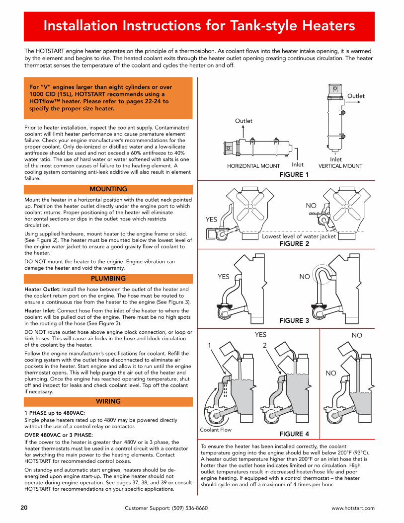
Installation Instructions for Tank-style Heaters
20 Customer Support: (509) 536-8660 www.hotstart.com
1 2
YES
NO
NO
Coolant FlowFIGURE 4
Prior to heater installation, inspect the coolant supply. Contaminatedcoolant will limit heater performance and cause premature elementfailure. Check your engine manufacturer’s recommendations for theproper coolant. Only de-ionized or distilled water and a low-silicateantifreeze should be used and not exceed a 60% antifreeze to 40%water ratio. The use of hard water or water softened with salts is oneof the most common causes of failure to the heating element. Acooling system containing anti-leak additive will also result in elementfailure.
Mount the heater in a horizontal position with the outlet neck pointedup. Position the heater outlet directly under the engine port to whichcoolant returns. Proper positioning of the heater will eliminatehorizontal sections or dips in the outlet hose which restrictscirculation.
Using supplied hardware, mount heater to the engine frame or skid.(See Figure 2). The heater must be mounted below the lowest level ofthe engine water jacket to ensure a good gravity flow of coolant tothe heater.
DO NOT mount the heater to the engine. Engine vibration candamage the heater and void the warranty.
Heater Outlet: Install the hose between the outlet of the heater andthe coolant return port on the engine. The hose must be routed toensure a continuous rise from the heater to the engine (See Figure 3).
Heater Inlet: Connect hose from the inlet of the heater to where thecoolant will be pulled out of the engine. There must be no high spotsin the routing of the hose (See Figure 3).
DO NOT route outlet hose above engine block connection, or loop orkink hoses. This will cause air locks in the hose and block circulationof the coolant by the heater.
Follow the engine manufacturer’s specifications for coolant. Refill thecooling system with the outlet hose disconnected to eliminate airpockets in the heater. Start engine and allow it to run until the enginethermostat opens. This will help purge the air out of the heater andplumbing. Once the engine has reached operating temperature, shutoff and inspect for leaks and check coolant level. Top off the coolantif necessary.
1 PHASE up to 480VAC:Single phase heaters rated up to 480V may be powered directlywithout the use of a control relay or contactor.
OVER 480VAC or 3 PHASE:If the power to the heater is greater than 480V or is 3 phase, theheater thermostats must be used in a control circuit with a contactorfor switching the main power to the heating elements. ContactHOTSTART for recommended control boxes.
On standby and automatic start engines, heaters should be de-energized upon engine start-up. The engine heater should notoperate during engine operation. See pages 37, 38, and 39 or consultHOTSTART for recommendations on your specific applications.
PLUMBING
WIRING
The HOTSTART engine heater operates on the principle of a thermosiphon. As coolant flows into the heater intake opening, it is warmedby the element and begins to rise. The heated coolant exits through the heater outlet opening creating continuous circulation. The heaterthermostat senses the temperature of the coolant and cycles the heater on and off.
To ensure the heater has been installed correctly, the coolanttemperature going into the engine should be well below 200°F (93°C).A heater outlet temperature higher than 200°F or an inlet hose that ishotter than the outlet hose indicates limited or no circulation. Highoutlet temperatures result in decreased heater/hose life and poorengine heating. If equipped with a control thermostat – the heatershould cycle on and off a maximum of 4 times per hour.
Outlet
Outlet
InletInlet
FIGURE 1
Lowest level of water jacket
YES
NO
YES NO
FIGURE 3
FIGURE 2
VERTICAL MOUNTHORIZONTAL MOUNT
MOUNTING
For “V” engines larger than eight cylinders or over1000 CID (15L), HOTSTART recommends using aHOTflow™ heater. Please refer to pages 22-24 tospecify the proper size heater.

P R O D U C T C A T A L O G
SE
CT
IO
N
3
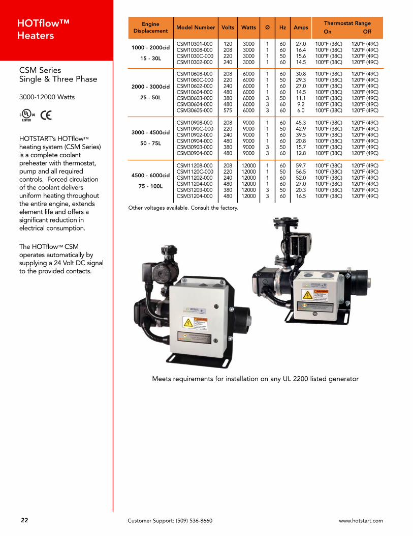
22 Customer Support: (509) 536-8660 www.hotstart.com
HOTflow™Heaters
CSM SeriesSingle & Three Phase
3000-12000 Watts
HOTSTART’s HOTflow™
heating system (CSM Series)is a complete coolantpreheater with thermostat,pump and all requiredcontrols. Forced circulationof the coolant deliversuniform heating throughoutthe entire engine, extendselement life and offers asignificant reduction inelectrical consumption.
The HOTflow™ CSMoperates automatically bysupplying a 24 Volt DC signalto the provided contacts.
Meets requirements for installation on any UL 2200 listed generator
EngineDisplacement
Model Number Volts Watts Ø Hz AmpsThermostat Range
On Off
1000 - 2000cid
15 - 30L
CSM10301-000CSM10308-000CSM1030C-000CSM10302-000
120208220240
3000300030003000
1111
60605060
27.016.415.614.5
100°F (38C) 120°F (49C)100°F (38C) 120°F (49C)100°F (38C) 120°F (49C)100°F (38C) 120°F (49C)
2000 - 3000cid
25 - 50L
CSM10608-000CSM1060C-000CSM10602-000CSM10604-000CSM30603-000CSM30604-000CSM30605-000
208220240480380480575
6000600060006000600060006000
1111333
60506060506060
30.829.327.014.511.19.26.0
100°F (38C) 120°F (49C)100°F (38C) 120°F (49C)100°F (38C) 120°F (49C)100°F (38C) 120°F (49C)100°F (38C) 120°F (49C)100°F (38C) 120°F (49C)100°F (38C) 120°F (49C)
3000 - 4500cid
50 - 75L
CSM10908-000CSM1090C-000CSM10902-000CSM10904-000CSM30903-000CSM30904-000
208220240480380480
900090009000900090009000
111133
605060605060
45.342.939.520.815.712.8
100°F (38C) 120°F (49C)100°F (38C) 120°F (49C)100°F (38C) 120°F (49C)100°F (38C) 120°F (49C)100°F (38C) 120°F (49C)100°F (38C) 120°F (49C)
4500 - 6000cid
75 - 100L
CSM11208-000CSM1120C-000CSM11202-000CSM11204-000CSM31203-000CSM31204-000
208220240480380480
120001200012000120001200012000
111133
605060605060
59.756.552.027.020.316.5
100°F (38C) 120°F (49C)100°F (38C) 120°F (49C)100°F (38C) 120°F (49C)100°F (38C) 120°F (49C)100°F (38C) 120°F (49C)100°F (38C) 120°F (49C)
Other voltages available. Consult the factory.

23Customer Support: (509) 536-8660 www.hotstart.com
Shipping Weight: 37lbs. (16.8kg)
Shipping Weight: 54lbs. (24.5kg)
Dimensional Drawingsinch, millimeter
Single Phase, 240v or Less
Single or Three Phase, Over 240v
* For CE compliant models, overalldepth measures 10.8” (274mm)
24 Customer Support: (509) 536-8660 www.hotstart.com
HOTflow™Heaters
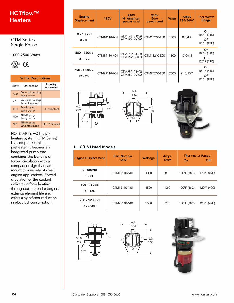
CTM SeriesSingle Phase
1000-2500 Watts
HOTSTART’s HOTflow™
heating system (CTM Series)is a complete coolantpreheater. It features anintegrated pump thatcombines the benefits offorced circulation with acompact design that canmount to a variety of smallengine applications. Forcedcirculation of the coolantdelivers uniform heatingthroughout the entire engine,extends element life andoffers a significant reductionin electrical consumption.
EngineDisplacement
120V240V
N. Americanpower cord
240VEuro
power cordWatts
Amps120/240V
ThermostatRange
0 - 500cid
0 - 8LCTM10110-A01 CTM10210-N00
CTM10210-A00 CTM10210-E00 1000 8.8/4.4
On100°F (38C)
Off120°F (49C)
500 - 750cid
8 - 12LCTM15110-A01 CTM15210-N00
CTM15210-A00 CTM15210-E00 1500 13.0/6.5
On100°F (38C)
Off120°F (49C)
750 - 1200cid
12 - 20LCTM25110-A01 CTM25210-N00
CTM25210-A00 CTM25210-E00 2500 21.3/10.7
On100°F (38C)
Off120°F (49C)
UL C/US Listed Models
Engine DisplacementPart Number
120VWattage
Amps120V
Thermostat Range
On Off
0 - 500cid
0 - 8LCTM10110-N01 1000 8.8 100°F (38C) 120°F (49C)
500 - 750cid
8 - 12LCTM15110-N01 1500 13.0 100°F (38C) 120°F (49C)
750 - 1200cid
12 - 20LCTM25110-N01 2500 21.3 100°F (38C) 120°F (49C)
Suffix Descriptions
Suffix Description IndustryApprovals
A003m cord, no plugLaing pump
A013m cord, no plugGrundfos pump
E00Schuko plugLaing pump
CE compliant
N00NEMA plugLaing pump
N01NEMA plugGrundfos pump
UL C/US listed

P R O D U C T C A T A L O G
SE
CT
IO
N
4

Remote thermostats for Weathertight and Class I, Group D Oil Heaters
(See page 33 for part numbers)
Use a thermostat with all lube oil heaters to protect the oil from overheating if the heater is energizedwhile the engine is hot or running. Lube oil heaters must always be installed in the sump with the entireheater submerged below the oil level at all times. See page 33 for remote thermostat part numbers.
120 Volt and 240 Volt are complete with a 3-prong plug.
HOTSTART lube oil haters eliminate the need for splice boxes or field wiring of the thermostat andheater.
Always mount the thermostat above and to one side of the heater for the most efficient control.
Thermostat
26 Customer Support: (509) 536-8660 www.hotstart.com
Oil HeatersOil
CapacityWeathertightHeater Only
Weathertight With Thermostat
Class 1, Group DHaz. LocationsHeater Only
Volts Watts Amps Watts/SqInch
3/8” N.P.T. THREAD WITH A 2 1/8” PROBE LENGTH
2 qts (2L)or Less
OW005100-000OW005200-000
——
——
120240
5050
.4
.220.020.0
1/2” N.P.T. THREAD WITH A 4” PROBE LENGTH
2 - 6 qts2 - 5.7L
OW212100-000OW212200-000
OW2121XX-000OW2122XX-000
OE212100-000OE212200-000
120240
125125
1.0.5
24.624.6
3/4” N.P.T. THREAD WITH A 5” PROBE LENGTH
1 - 5 gal3.8 - 19L
OW415100-000OW415200-000
OW4151XX-000OW4152XX-000
OE415100-000OE415200-000
120240
150150
1.3.6
14.614.6
5 - 15 gal19 - 57L
OW430100-000OW430800-000OW430200-000
OW4301XX-000OW4308XX-000OW4302XX-000
OE430100-000OE430800-000OE430200-000
120208240
300300300
2.61.11.2
29.329.329.3
1” N.P.T. THREAD WITH A 5 1/4” PROBE LENGTH
1 - 5 gal3.8 - 19L
OW615100-000OW615200-000
OW6151XX-000OW6152XX-000
OE615100-000OE615200-000
120240
150150
1.3.6
10.710.7
5 - 15 gal19 - 57L
OW630100-000OW630800-000OW630200-000OW630700-000
——
OW6301XX-000OW6308XX-000OW6302XX-000OW6307XX-000
——
OE630100-000OE630800-000OE630200-000OE630700-000OE630300-000OE630400-000
120208240277380480
300300300300300300
2.61.61.21.11.0.6
21.421.421.421.421.421.4
15 - 30 gal57 - 113L
OW650100-000OW650800-000OW650200-000OW650700-000
———
OW6501XX-000OW6508XX-000OW6502XX-000OW6507XX-000
———
OE650100-000OE650800-000OE650200-000OE650700-000OE650300-000OE650400-000OE650500-000
120208240277380480575
500500500500500500500
4.12.42.01.81.31.00.8
35.735.735.735.735.735.735.7
C US
NOTES: Weathertight heaters are standard with a 4 ft. oil and heat resistant power cord - no plug.Class 1, Group D heaters are standard with 18” of lead wire for connection to the powerleads in an approved splice box.
To specify temperature range ofthermostat, insert code from chart inplace of the XX in model number.
Example:
Desired Temp. Range 80° - 100°FModel Number: OW2121XX-000Order as: OW212108-000
Temperature RangeCode
ON OFF
60°F (15C)80°F (27C)
100°F (38C)120°F (49C)
80°F (27C)100°F (38C)120°F (49C)140°F (60C)
06081012
See p.33 for remote thermostatassembly part numbers
Weathertight remote thermostat
Class I, Group DHazardous Location
27Customer Support: (509) 536-8660 www.hotstart.com
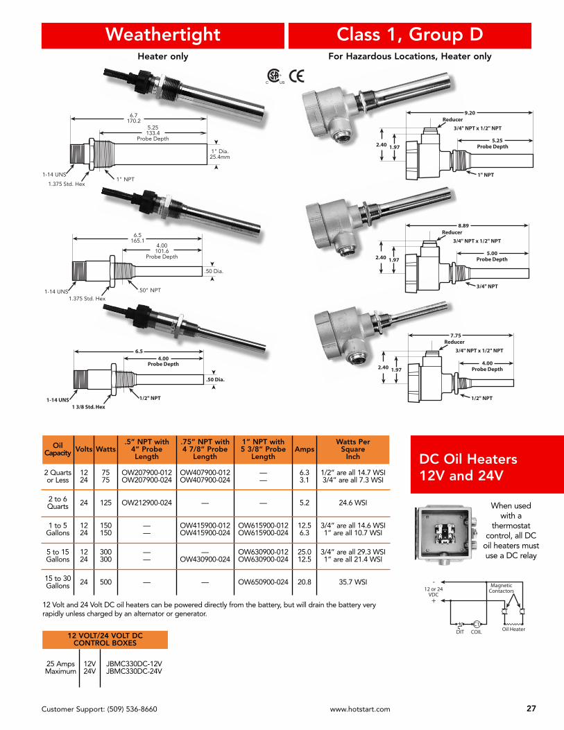
Heater only
Class 1, Group DWeathertightFor Hazardous Locations, Heater only
7.75
4.00Probe Depth
1/2" NPT
1.972.40
3/4" NPT x 1/2" NPT
Reducer
8.89
3/4" NPT x 1/2" NPT
5.00Probe Depth
3/4" NPT
1.972.40
Reducer
9.20
3/4" NPT x 1/2" NPT
5.25Probe Depth
1" NPT
1.972.40
Reducer
6.54.00
Probe Depth
.50 Dia.
1/2" NPT
1 3/8 Std. Hex1-14 UNS
C US
6.7170.2
5.25133.4
Probe Depth
1" Dia.25.4mm
1" NPT1.375 Std. Hex
1-14 UNS
6.5165.1
4.00101.6
Probe Depth
.50 Dia.
.50" NPT
1.375 Std. Hex1-14 UNS
Oil Capacity Volts Watts
.5” NPT with 4” ProbeLength
.75” NPT with4 7/8” Probe
Length
1” NPT with 5 3/8” Probe
LengthAmps
Watts PerSquare
Inch
2 Quartsor Less
1224
7575
OW207900-012OW207900-024
OW407900-012OW407900-024
——
6.33.1
1/2” are all 14.7 WSI3/4” are all 7.3 WSI
2 to 6Quarts 24 125 OW212900-024 — — 5.2 24.6 WSI
1 to 5Gallons
1224
150150
——
OW415900-012OW415900-024
OW615900-012OW615900-024
12.56.3
3/4” are all 14.6 WSI1” are all 10.7 WSI
5 to 15Gallons
1224
300300
——
—OW430900-024
OW630900-012OW630900-024
25.012.5
3/4” are all 29.3 WSI1” are all 21.4 WSI
15 to 30Gallons 24 500 — — OW650900-024 20.8 35.7 WSI
DC Oil Heaters12V and 24V
12 Volt and 24 Volt DC oil heaters can be powered directly from the battery, but will drain the battery veryrapidly unless charged by an alternator or generator.
-
+
12 or 24VDC
DIT COIL
C1
C1 C1
MagneticContactors
Oil Heater
When usedwith a
thermostatcontrol, all DC
oil heaters mustuse a DC relay
12 VOLT/24 VOLT DC CONTROL BOXES
25 AmpsMaximum
12V24V
JBMC330DC-12VJBMC330DC-24V

28 Customer Support: (509) 536-8660 www.hotstart.com
IndustrialImmersion Heaters
2” Screw PlugFor Lube Oils, Hydraulicsand Diesel Fuels
With Fixed-Setting, Built-InThermostat (Pg. 29) orAdjustable Thermostat (Pg.31)
Weather Tight NEMA 4Enclosure
Class I, Group D heaters with thermostat for hazardous locations also available. Substitute the letter “W” in part number with the letter “E” to specify Class I, Group D heaters.
Industrial Immersion Heaters are also available for coolants and other process heating. Call factory.
Models for larger capacities than shown are available. Call factory.
OilCapacity
HIGH LIMIT THERMOSTAT CONTROL SETTINGVolts Watts Amps Watts
Sq. In.On 60°F (15C)Off 80°F (27C)
On 80°F (27C)Off 100°F (38C)
On 100°F (38C)Off 120°F (49C)
SINGLE PHASE — 2” N.P.T. WITH A 12” PROBE LENGTH
30 - 45Gallons
113-170L
E01011W-156A-00E01081W-156A-00E01021W-156A-00E01071W-156A-00
E01011W-158A-00E01081W-158A-00E01021W-158A-00E01071W-158A-00
E01011W-151A-00E01081W-151A-00E01021W-151A-00E01071W-151A-00
120208240277
1000100010001000
8.34.84.23.6
17.017.017.017.0
45 - 60Gallons
170-227L
E01511W-156A-00E01581W-156A-00E01521W-156A-00E01571W-156A-00
E01511W-158A-00E01581W-158A-00E01521W-158A-00E01571W-158A-00
E01511W-151A-00E01581W-151A-00E01521W-151A-00E01571W-151A-00
120208240277
1500150015001500
12.57.26.35.4
17.017.017.017.0
THREE PHASE — 2” N.P.T. WITH A 12” PROBE LENGTH
30 - 45Gallons
113-170L
E01083W-106A-00E01023W-106A-00E01033W-106A-00
E01083W-108A-00E01023W-108A-00E01033W-108A-00
E01083W-101A-00E01023W-101A-00E01033W-101A-00
208240380
100010001000
2.82.41.5
11.011.011.0
45 - 60Gallons
170-227L
E01583W-156A-00E01523W-156A-00E01533W-156A-00E01543W-156A-00
E01583W-158A-00E01523W-158A-00E01533W-158A-00E01543W-158A-00
E01583W-151A-00E01523W-151A-00E01533W-151A-00E01543W-151A-00
208240380480
1500150015001500
4.23.62.31.8
17.017.017.017.0
SINGLE PHASE — 2” N.P.T. WITH A 18” PROBE LENGTH
60 - 90Gallons
227-341L
E02011W-156A-00E02081W-156A-00E02021W-156A-00E02071W-156A-00E02031W-156A-00E02041W-156A-00
E02011W-158A-00E02081W-158A-00E02021W-158A-00E02071W-158A-00E02031W-158A-00E02041W-158A-00
E02011W-151A-00E02081W-151A-00E02021W-151A-00E02071W-151A-00E02031W-151A-00E02041W-151A-00
120208240277380480
200020002000200020002000
16.79.68.47.25.34.2
14.014.014.014.014.014.0
THREE PHASE — 2” N.P.T. WITH A 18” PROBE LENGTH
60 - 90Gallons
227-341L
E02083W-156A-00E02023W-156A-00E02033W-156A-00E02043W-156A-00
E02083W-158A-00E02023W-158A-00E02033W-158A-00E02043W-158A-00
E02083W-151A-00E02023W-151A-00E02033W-151A-00E02043W-151A-00
208240380480
2000200020002000
5.64.83.02.4
14.014.014.014.0

29Customer Support: (509) 536-8660 www.hotstart.com
2” Screw Plug1.0
2" NPT
3.2512" OR 18" DIM
3.60
Thermostat Sensor
Heat Shrink Cover
Sensor Seat
FIXED THERMOSTAT ASSEMBLY
HOTSTART immersion heaters are complete with a fixed-setting, built-in thermostat (shownbelow). All models are also available with an adjustable thermostat (pg. 31).
Ideal for heating hydraulic reservoirs on construction equipment and the sumps of large industrialengines.
TYPICAL WIRING DIAGRAMS
Three phase and single phase above 277 VAC Single phase 277 VAC and below
NOTES: On applications where level offluid is subject to change, aliquid level switch mounted aminimum of 3 to 4 inchesabove element isrecommended. Liquid levelswitch is not included withheater.
All 380 Volt and 480 Voltheaters must be used inconjunction with contactor andcontrol transformer.
All three phase heaters mustbe used with a contactor. Seepages 37 & 38.
Higher or lower temperatureranges are available. ConsultHOTSTART.
“W” Weathertight ModelNEMA 4
C US
PowerIn
PowerIn
Ground GroundFuse
Fuse
Transformer
LiquidLevel
Switch
LiquidLevel
Switch
Temp.Control
Temp.Control
ElementContactor Coil
HeatingElement
HeatingElement
“E” Hazardous Location ModelNEMA 4 & 7
ELECTRICAL RATING
15 Amps at 120 VAC10 Amps at 240 VAC10 Amps at 277 VAC
4.4
12" OR 18" DIM
2" NPT
1.3 4.3
“W” Weathertight ModelNEMA 4
“E” Hazardous Location ModelNEMA 4 & 7
Thermostat assembly shown in “EP” housing.
Industrial Immersion Heaters
30 Customer Support: (509) 536-8660 www.hotstart.com
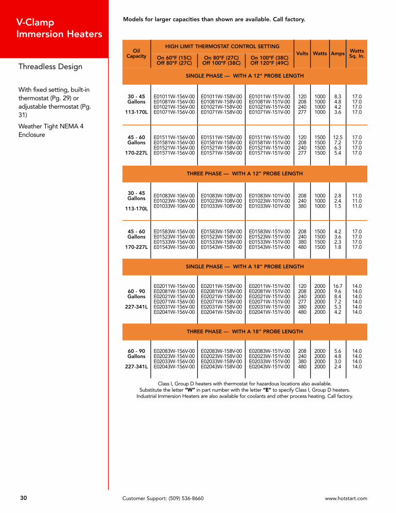
V-ClampImmersion Heaters
Threadless Design
With fixed setting, built-inthermostat (Pg. 29) oradjustable thermostat (Pg.31)
Weather Tight NEMA 4Enclosure
Class I, Group D heaters with thermostat for hazardous locations also available. Substitute the letter “W” in part number with the letter “E” to specify Class I, Group D heaters.
Industrial Immersion Heaters are also available for coolants and other process heating. Call factory.
Models for larger capacities than shown are available. Call factory.
OilCapacity
HIGH LIMIT THERMOSTAT CONTROL SETTINGVolts Watts Amps Watts
Sq. In.On 60°F (15C)Off 80°F (27C)
On 80°F (27C)Off 100°F (38C)
On 100°F (38C)Off 120°F (49C)
SINGLE PHASE — WITH A 12” PROBE LENGTH
30 - 45Gallons
113-170L
E01011W-156V-00E01081W-156V-00E01021W-156V-00E01071W-156V-00
E01011W-158V-00E01081W-158V-00E01021W-158V-00E01071W-158V-00
E01011W-151V-00E01081W-151V-00E01021W-151V-00E01071W-151V-00
120208240277
1000100010001000
8.34.84.23.6
17.017.017.017.0
45 - 60Gallons
170-227L
E01511W-156V-00E01581W-156V-00E01521W-156V-00E01571W-156V-00
E01511W-158V-00E01581W-158V-00E01521W-158V-00E01571W-158V-00
E01511W-151V-00E01581W-151V-00E01521W-151V-00E01571W-151V-00
120208240277
1500150015001500
12.57.26.35.4
17.017.017.017.0
THREE PHASE — WITH A 12” PROBE LENGTH
30 - 45Gallons
113-170L
E01083W-106V-00E01023W-106V-00E01033W-106V-00
E01083W-108V-00E01023W-108V-00E01033W-108V-00
E01083W-101V-00E01023W-101V-00E01033W-101V-00
208240380
100010001000
2.82.41.5
11.011.011.0
45 - 60Gallons
170-227L
E01583W-156V-00E01523W-156V-00E01533W-156V-00E01543W-156V-00
E01583W-158V-00E01523W-158V-00E01533W-158V-00E01543W-158V-00
E01583W-151V-00E01523W-151V-00E01533W-151V-00E01543W-151V-00
208240380480
1500150015001500
4.23.62.31.8
17.017.017.017.0
SINGLE PHASE — WITH A 18” PROBE LENGTH
60 - 90Gallons
227-341L
E02011W-156V-00E02081W-156V-00E02021W-156V-00E02071W-156V-00E02031W-156V-00E02041W-156V-00
E02011W-158V-00E02081W-158V-00E02021W-158V-00E02071W-158V-00E02031W-158V-00E02041W-158V-00
E02011W-151V-00E02081W-151V-00E02021W-151V-00E02071W-151V-00E02031W-151V-00E02041W-151V-00
120208240277380480
200020002000200020002000
16.79.68.47.25.34.2
14.014.014.014.014.014.0
THREE PHASE — WITH A 18” PROBE LENGTH
60 - 90Gallons
227-341L
E02083W-156V-00E02023W-156V-00E02033W-156V-00E02043W-156V-00
E02083W-158V-00E02023W-158V-00E02033W-158V-00E02043W-158V-00
E02083W-151V-00E02023W-151V-00E02033W-151V-00E02043W-151V-00
208240380480
2000200020002000
5.64.83.02.4
14.014.014.014.0

31Customer Support: (509) 536-8660 www.hotstart.com
Threadless Design
With fixed setting, built-inthermostat (Pg. 29). Oradjustable thermostat (shownbelow). Consult factory formodel number.
Ideal for heating hydraulicreservoirs on constructionequipment and the sumps oflarge industrial engines.
V-ClampImmersion Heaters
CoverGasket
Fasteners, CoverGround Screw
Ground Lug
Thermostat
Element Assembly
ADJUSTABLE THERMOSTAT ASSEMBLY
Call HOTSTART for complete model number featuring adjustable thermostat.
C US
NOTE: Replacement elements supplied with “O” Ring only.For new installations, order kit - P/N VC-SK. Kit Includes:
1 – steel weldable adapter1 – worm-drive V-Clamp1 – “O” Ring
NOTES: On applications where level offluid is subject to change, aliquid level switch mounted aminimum of 3 to 4 inchesabove element isrecommended. Liquid levelswitch is not included withheater.
All 380 Volt and 480 Voltheaters must be used inconjunction with contactor andcontrol transformer.
All three phase heaters mustbe used with a contactor. Seepages 37 & 38.
Higher or lower temperatureranges are available. ConsultHOTSTART.
O-ring
V-Clamp
3.7212”or 18” DIM
Weldable Adapter
3.60
“E” Hazardous Location ModelNEMA 4 & 7
“W” Weathertight ModelNEMA 4
TEMPERATURE RANGE
OFF 70°F to 210°F
ELECTRICAL RATING
30 Amps at 125 VAC30 Amps at 240 VAC30 Amps at 277 VAC20 Amps at 480 VAC
Nominal thermal differential is 8°F

P R O D U C T C A T A L O G
5
SE
CT
IO
N
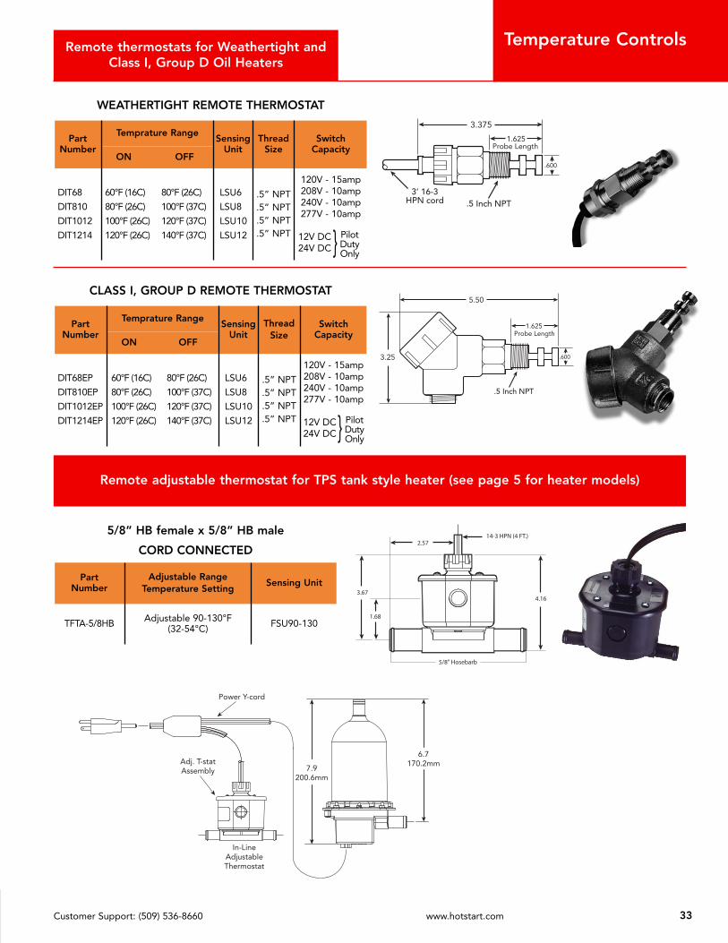
Remote thermostats for Weathertight andClass I, Group D Oil Heaters
WEATHERTIGHT REMOTE THERMOSTAT
Part Number
Temprature RangeSensing
UnitThread
SizeSwitch
CapacityON OFF
DIT68
DIT810
DIT1012
DIT1214
60°F (16C) 80°F (26C)
80°F (26C) 100°F (37C)
100°F (26C) 120°F (37C)
120°F (26C) 140°F (37C)
LSU6
LSU8
LSU10
LSU12
.5” NPT
.5” NPT
.5” NPT
.5” NPT
120V - 15amp208V - 10amp240V - 10amp277V - 10amp
12V DC24V DC
CLASS I, GROUP D REMOTE THERMOSTAT
Part Number
Temprature RangeSensing
UnitThread
SizeSwitch
CapacityON OFF
DIT68EP
DIT810EP
DIT1012EP
DIT1214EP
60°F (16C) 80°F (26C)
80°F (26C) 100°F (37C)
100°F (26C) 120°F (37C)
120°F (26C) 140°F (37C)
LSU6
LSU8
LSU10
LSU12
.5” NPT
.5” NPT
.5” NPT
.5” NPT
120V - 15amp208V - 10amp240V - 10amp277V - 10amp
12V DC24V DC
5/8” HB female x 5/8” HB male
CORD CONNECTED
Part Number
Adjustable RangeTemperature Setting
Sensing Unit
TFTA-5/8HB Adjustable 90-130°F(32-54°C) FSU90-130
14-3 HPN (4 FT.)2.57
4.16
5/8" Hosebarb
1.68
3.67
Remote adjustable thermostat for TPS tank style heater (see page 5 for heater models)
In-LineAdjustableThermostat
6.7170.2mm
7.9200.6mm
Power Y-cord
Adj. T-statAssembly
Temperature Controls
PilotDutyOnly}
PilotDutyOnly}
33Customer Support: (509) 536-8660 www.hotstart.com
34 Customer Support: (509) 536-8660 www.hotstart.com
1.25
2.25
1" NPT Inlet1.0
5.0
1/2" NPT Conduit Opening
3.0
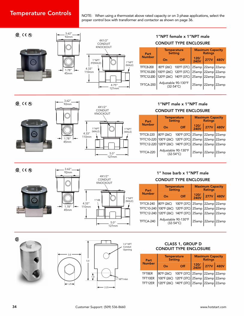
1”NPT female x 1”NPT male
CONDUIT TYPE ENCLOSURE
Part Number
Temperature Setting
Maximum CapacityRatings
On Off 120/240V 277V 480V
TFTC8-200
TFTC10-200
TFTC12-200
80°F (26C) 100°F (37C)
100°F (26C) 120°F (37C)
120°F (26C) 140°F (37C)
25amp
25amp
25amp
22amp
22amp
22amp
22amp
22amp
22amp
TFTCA-200 Adjustable 90-130°F(32-54°C) 25amp 22amp 22amp
1”NPT male x 1”NPT male
CONDUIT TYPE ENCLOSURE
Part Number
Temperature Setting
Maximum CapacityRatings
On Off 120/240V 277V 480V
TFTC8-220
TFTC10-220
TFTC12-220
80°F (26C) 100°F (37C)
100°F (26C) 120°F (37C)
120°F (26C) 140°F (37C)
25amp
25amp
25amp
22amp
22amp
22amp
22amp
22amp
22amp
TFTCA-220 Adjustable 90-130°F(32-54°C) 25amp 22amp 22amp
Temperature Controls
1” hose barb x 1”NPT male
CONDUIT TYPE ENCLOSURE
Part Number
Temperature Setting
Maximum CapacityRatings
On Off 120/240V 277V 480V
TFTC8-240
TFTC10-240
TFTC12-240
80°F (26C) 100°F (37C)
100°F (26C) 120°F (37C)
120°F (26C) 140°F (37C)
25amp
25amp
25amp
22amp
22amp
22amp
22amp
22amp
22amp
TFTCA-240 Adjustable 90-130°F(32-54°C) 25amp 22amp 22amp
CLASS 1, GROUP DCONDUIT TYPE ENCLOSURE
Part Number
Temperature Setting
Maximum CapacityRatings
On Off 120/240V 277V 480V
TFT8ER
TFT10ER
TFT12ER
80°F (26C) 100°F (37C)
100°F (26C) 120°F (37C)
120°F (26C) 140°F (37C)
25amp
25amp
25amp
22amp
22amp
22amp
22amp
22amp
22amp
NOTE: When using a thermostat above rated capacity or on 3 phase applications, select theproper control box with transformer and contactor as shown on page 36.
C US
C US
C US
35Customer Support: (509) 536-8660 www.hotstart.com
60 95
125
155
185
215250
LO
3.06
1.87
3.36
.078Dia.
5.06
6.38
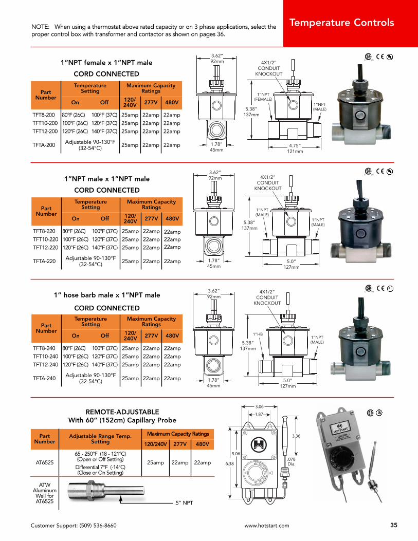
1”NPT female x 1”NPT male
CORD CONNECTED
Part Number
Temperature Setting
Maximum CapacityRatings
On Off 120/240V 277V 480V
TFT8-200
TFT10-200
TFT12-200
80°F (26C) 100°F (37C)
100°F (26C) 120°F (37C)
120°F (26C) 140°F (37C)
25amp
25amp
25amp
22amp
22amp
22amp
22amp
22amp
22amp
TFTA-200 Adjustable 90-130°F(32-54°C) 25amp 22amp 22amp
REMOTE-ADJUSTABLEWith 60” (152cm) Capillary Probe
Part Number
Adjustable Range Temp. Setting
Maximum Capacity Ratings
120/240V 277V 480V
AT6525
65 - 250°F (18 - 121°C)(Open or Off Setting)
Differential 7°F (-14°C)(Close or On Setting)
25amp 22amp 22amp
ATWAluminumWell forAT6525 .5” NPT
C US
Temperature Controls
1”NPT male x 1”NPT male
CORD CONNECTED
Part Number
Temperature Setting
Maximum CapacityRatings
On Off 120/240V 277V 480V
TFT8-220
TFT10-220
TFT12-220
80°F (26C) 100°F (37C)
100°F (26C) 120°F (37C)
120°F (26C) 140°F (37C)
25amp
25amp
25amp
22amp
22amp
22amp
22amp22amp22amp
TFTA-220 Adjustable 90-130°F(32-54°C) 25amp 22amp 22amp
1” hose barb male x 1”NPT male
CORD CONNECTED
Part Number
Temperature Setting
Maximum CapacityRatings
On Off 120/240V 277V 480V
TFT8-240
TFT10-240
TFT12-240
80°F (26C) 100°F (37C)
100°F (26C) 120°F (37C)
120°F (26C) 140°F (37C)
25amp
25amp
25amp
22amp
22amp
22amp
22amp
22amp
22amp
TFTA-240 Adjustable 90-130°F(32-54°C) 25amp 22amp 22amp
NOTE: When using a thermostat above rated capacity or on 3 phase applications, select theproper control box with transformer and contactor as shown on pages 36.
C US
C US
36 HOTSTART Engine Heating Spokane, WA
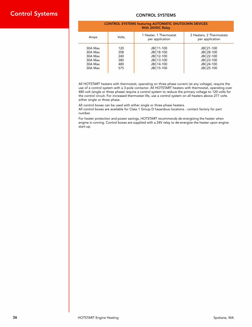
Control Systems CONTROL SYSTEMS
CONTROL SYSTEMS featuring AUTOMATIC SHUTDOWN DEVICESWith 24VDC Relay
Amps Volts1 Heater, 1 Thermostat
per application2 Heaters, 2 Thermostats
per application
30A Max30A Max30A Max30A Max30A Max30A Max
120208240380480575
JBC11-100JBC18-100JBC12-100JBC13-100JBC14-100JBC15-100
JBC21-100JBC28-100JBC22-100JBC23-100JBC24-100JBC25-100
All HOTSTART heaters with thermostat, operating on three phase current (at any voltage), require theuse of a control system with a 3-pole contactor. All HOTSTART heaters with thermostat, operating over480 volt (single or three phase) require a control system to reduce the primary voltage to 120 volts forthe control circuit. For increased thermostat life, use a control system on all heaters above 277 voltseither single or three phase.
All control boxes can be used with either single or three phase heaters.All control boxes are available for Class 1 Group D hazardous locations - contact factory for partnumber.
For heater protection and power savings, HOTSTART recommends de-energizing the heater whenengine is running. Control boxes are supplied with a 24V relay to de-energize the heater upon enginestart-up.

37Customer Support: (509) 536-8660 www.hotstart.com
Control Box SystemComponents
L1
L2
L3
Power In480V 3PH
Equipment Ground(must be grounded)
Equipment Ground(must be grounded)
H4 H1H2 H3
ControlTransformer
480V. PRI.
1A. Fuses
X1 X2120V. 50VA
1/2A. Fuse
Line Line
Load Load
PressureSwitch
ContactorCoil
ContactorCoil
C1
C2
2
2
4
5
Thermostat
Thermostat
3
3
MagneticContactors
C1 C1 C1 C2 C2 C2
E1 E2 E3 E4 E5 E6
10A. Fuses
HeatingElement
HeatingElement
3 Phase Only
L3
L1
Power In480V.
1 or 3Ø30 AMP
Transformer480V. PRI.
50VAH1 H3 H2 H4
1A. Fuses
X1
X1
X2120V Sec.
1/2A. Fuse
1
3 2C1
ContactorCoilThermostat
Control
MagneticContactor
L1 L2 L3
E1 E2 E3
C1 C1 C1
HeatingElement
These control systems allow for quick electrical installation of all HOTSTART engine preheaters.They are designed as a time and labor saving component. They are especially useful oninstallations that require two coolant heaters or combinations of a coolant heater and oilheater/hydraulic heater etc.
All control boxes on this and preceding page are NEMA 12 & 13.
Model JBC14-100With pressure switch
or
Model JBC24-100With 24 volt relay
To control one 480 volt heater at maximum 30 amps on manual start engine.
To control two 480 volt heaters at maximum 30 amps on automatic start engines.

38 Customer Support: (509) 536-8660 www.hotstart.com

P R O D U C T C A T A L O G
SE
CT
IO
N
6

40 HOTSTART Engine Heating Spokane, WA
Battery Heating Pads
Battery heater not recommended for nickel cadmium batteries.When batteries are placed in an insulated battery box, a thermostat isrecommended to sense battery box temperature to prevent overheating thebattery.
Accessories For Multiple Battery Heating
Typical Connection - 2 Batteries on Each Side of Vehicle
100
80
60
40
20
0-20 0 +20 +40 +60 +80
Ambient Temperature, ˚F
Perc
ent
of B
atte
ry C
ran
kin
g P
ow
er
Standard Pad for Single Battery Special Pads for Multiple Batteries
Style A
6" HPN
A
B
KB
7515
-D
KB
7515
-D
KB
7515
-D
KB
7515
-S
Left Side Battery Box Right Side Battery Box
BEC-6
BY-T68 BPC-61
Ground
2 FT4 FT6 FT8 FT
3 FT6 FT
16-3 HPN
15.375" 15.375"
15.375"
CORD, 16-3 HPN
ModelNumber Volts Watts Amps
NominalDimensions Batt.
Size Style
A B
KB5015KB5015-SKB5015-D
120120120
505050
.42
.42
.42
8 1/48 1/48 1/4
131313
4D4D4D
ABC
KB7515KB7515-SKB7515-D
120120120
757575
.63
.63
.63
10 1/210 1/210 1/2
19 1/219 1/219 1/2
8D8D8D
ABC
KB7523KB7523-SKB7523-D
240240240
757575
.31
.31
.31
10 1/210 1/210 1/2
19 1/219 1/219 1/2
8D8D8D
ABC
EXTENSION CORDS
Model Length
BEC-2 2’ (61cm)
BEC-4 4’ (122cm)
BEC-6 6’ (183cm)
BEC-8 8’ (244cm)
POWER SUPPLY CORDS
Model Length Volts
BPC-31 3’ (91cm) 120
BPC-32 3’ (91cm) 240
BPC-61 6’ (183cm) 120
BPC-62 6’ (183cm) 240
THERMOSTAT & “Y” CORD ASSEMBLY
ModelTemperature Control
On Off
BY-T68 60°F (16°C) 80°F (27°C)
B
A
Style C Style B
9.00REF TYP
9.00REF TYP
16-3 HPN
16-3 HPN
A
B
41Customer Support: (509) 536-8660 www.hotstart.com
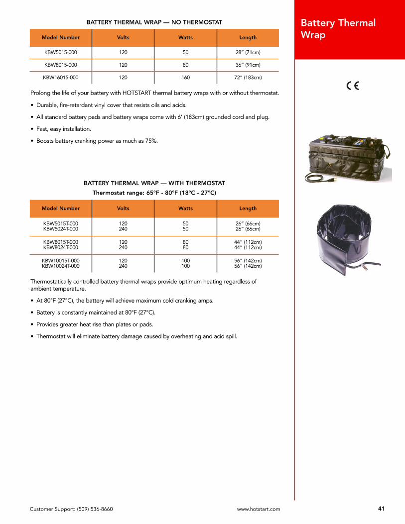
Battery ThermalWrap
Prolong the life of your battery with HOTSTART thermal battery wraps with or without thermostat.
• Durable, fire-retardant vinyl cover that resists oils and acids.
• All standard battery pads and battery wraps come with 6’ (183cm) grounded cord and plug.
• Fast, easy installation.
• Boosts battery cranking power as much as 75%.
Thermostatically controlled battery thermal wraps provide optimum heating regardless ofambient temperature.
• At 80°F (27°C), the battery will achieve maximum cold cranking amps.
• Battery is constantly maintained at 80°F (27°C).
• Provides greater heat rise than plates or pads.
• Thermostat will eliminate battery damage caused by overheating and acid spill.
BATTERY THERMAL WRAP — NO THERMOSTAT
Model Number Volts Watts Length
KBW5015-000 120 50 28” (71cm)
KBW8015-000 120 80 36” (91cm)
KBW16015-000 120 160 72” (183cm)
BATTERY THERMAL WRAP — WITH THERMOSTAT
Thermostat range: 65°F - 80°F (18°C - 27°C)
Model Number Volts Watts Length
KBW5015T-000KBW5024T-000
120240
5050
26” (66cm)26” (66cm)
KBW8015T-000KBW8024T-000
120240
8080
44” (112cm)44” (112cm)
KBW10015T-000KBW10024T-000
120240
100100
56” (142cm)56” (142cm)

42 Customer Support: (509) 536-8660 www.hotstart.com
SiliconePad Heaters
Flexible, Versatile and Easy to Install.HOTSTART adhesive pad heaters can be used on oil pans, hydraulic reservoirs, engine blocks,hydraulic cylinders and diesel fuel tanks.
• Easy peel and stick application
• Etched foil heating element for optimal heat transfer and long life
• Durable silicone/fiberglass cover resists abrasion
• Assembled with a standard 6’ (183cm) HPN cord and plug (240V without plug)
CAUTION: Do not use pads with higher than recommended wattage for specific oil capacities.For use on metal surfaces only.
Not for use on batteries
Model Number Dimensions Volts Watts
AF10015AF10024
4” x 5”(101.6 x 127.0 mm)
120240
100100
AF15015AF15024
4” x 5”(101.6 x 127.0 mm)
120240
150150
AF25015AF25024
5” x 6”(127.0 x 152.4 mm)
120240
250250
AF40015AF40024
6” x 8”(152.4 x 203.2 mm)
120240
400400
ApplicationGuidline 100 Watt 150 Watt 250 Watt 400 Watt
Engine oil pan 2 - 5 quarts1.9 - 4.7L
5 - 8 quarts4.7 - 7.6L
2 - 5 gallons7.6 - 19L
5 - 8 gallons19 - 30.3L
Diesel Tank 5 - 7 gallons19 - 26.5L
7 - 10 gallons26.5 - 37.9L
10 - 20 gallons37.9 - 75.7L
20 - 30 gallons75.7 - 113.5L
Hydraulic Tank 1 - 5 gallons 5 - 10 gallons19 - 37.9L
10 - 20 gallons37.9 - 75.7L
20 - 30 gallons75.7 - 113.5L
Water Tank up - 2 gallons 2 - 4 gallons 4 - 7 gallons 7 - 10 gallons26.5 - 37.9L

P R O D U C T C A T A L O G
SE
CT
IO
N
7

* If supplemental oil heating is desired, this column gives the correct thread size in oil pan. See NOTE on page 54.
44 Customer Support: (509) 536-8660 www.hotstart.com
In-BlockDirect Immersion Heaters
Note: In-block heaters are complete with 2-wire w/ground 6 footHPN cord and plug. For cord replacements or “Y” thermocordenergy saver, please reference page 56.
Engine ModelPart Number
120 VoltsPart Number
240 Volts Watts Application InformationHeat Shield
RequiredOil Heater
Thread Size* Product Image
Allis Chalmers670T & I685T & I
6138LT, T & I25000 (844 CID)
AC-101CATV-151
AC-102CATV-152
10001500
Replaces 1” thread-in plug on the oilcooler at rear of the engine on the rightside. Note that not all of the engines
have this opening.
Case/IH – Agricultural
ALL 4 CYL 390ALL 6 CYL 590
CUB-751FPCUB-101FPCUB-151FP
CUB-752FPCUB-102FPCUB-152FP
75010001500
Inserts in any of the freeze plugs rightside of engine 22mm
ALL 6 CYL 830 CUC-151FP CUC-152FP 1500 Inserts in the freeze plug right rear of theblock 22mm
CaterpillarC-10C-12 TF121-000 TF122-000 1250 Replaces the 1” threaded plug
in the oil cooler bonnet YES 1” NPT
C-9 Non ACERTC-15 Non ACERTC-16 Non ACERT
CATV-151 CATV-152 1500C-9 Only: Mount in rear face of blockC-15, C-16: Mount in rear oil cooler
bonnet from the back end1” NPT
C7 ACERT3126
FP101-001FP151-001
FP102-001FP152-001
10001500
Replace 44mm frost plug on right handside of engine just below the turbo
charger.YES
C7 ACERT rear port TL101-000 TL102-000 Replace 1-1/16” plug in the rear of theblock
C9 ACERT CATV-151 CATV-152 1500 Replace 1” NPT plug in the right rear ofthe engine block
C11 ACERTC13 ACERT TF151-008 TF152-008 1500
Replace any of the 1-5/16” plugs in rearof oil cooler on the right hand side of the
engine
Check ExhaustRouting
1 5/16”STOR
C15 ACERTw/o breaksaver TF151-009 TF152-009 1500
Replace 1-3/16” plug in rear of the oilcooler on the right hand side of the
engine
C15 ACERTwith breaksaver TF151-008 TF152-008 1500 Replace 1-5/16” plug in the oil cooler on
the righ handside of engine
C9 2007 ACERTC13 2007 ACERTC15 2007 ACERT
TF151-012 TF152-012 1500Replace 1-3/16” plug in the rear of theoil cooler on the right hand side of the
engine
1674 CATB-151 CATB-152 1500 Replaces the 1-1/2” thread-in plug on the right side of the engine
1693 & D343 CATC-151 CATC-152 1500 Replaces water jacket access plate on theleft side of the engine
1693T & 1693TA CATC-151-S CATC-152-S 1500 Replaces water jacket access plate on theleft side of the engine
3013 1.5L3014 2.0L FP531-003 FP532-003 530 Replaces 40mm core plug on the front,
left side of the engine
C US

45Customer Support: (509) 536-8660 www.hotstart.com
* If supplemental oil heating is desired, this column gives the correct thread size in oil pan. See NOTE on page 54.
In-BlockDirect Immersion Heaters
Note: In-block heaters are complete with 2-wire w/ground 6 footHPN cord and plug. For cord replacements or “Y” thermocordenergy saver, please reference page 56.
Engine ModelPart Number
120 VoltsPart Number
240 Volts Watts Application InformationHeat Shield
RequiredOil Heater
Thread Size* Product Image
Caterpillar — Continued
3024 2.22L FP531-003 FP532-003 530 Replaces 40mm core plug on the front,left side of the engine
3034 2.95L FP531-001 FP532-001 530 Replaces 50mm core plug located atback of head
3044 3.3L PF531-001 PF532-001 530 Mounts in oval shaped opening on theright of the engine
3046 5.0L PF531-000 PF532-000 530 Replaces 35mm core plug located at rearof engine, left side
3054 3.99L3054B 4.23L
PER-751FPPER-101FP
PER-752FPPER-102FP
7501000
Mounts in the 1-1/4” freeze plug openingon the left side of the engine
3054C PER-751FP PER-752FP 750 Mounts in 1-1/4” freeze plug at left rearof engine
3056 6.0L PER-151FP PER-152FP 1500 Mounts in the 1-1/2” freeze plug on theright side of the engine
31143116
FP101-001FP151-001
FP102-001FP152-001
10001500
Replaces the core plug on the right sideof the engine just below the
turbochargerYES 11/16”X12
3176 10.3Lthrough 1995
DD8L-101CAT-12015TF151-001
DD8L-102CAT-12023TF152-001
100012501500
Replaces the 3/4” plug on the right sideof
the engine just below the head.1” NPT
3176 10.3L1996 and later TF121-000 TF122-000 1250 Replaces the 1” threaded plug in the oil
cooler bonnet YES 11/16”X12
3196 12.0L TF121-000 TF122-000 1250 Replaces 1” threaded plug in oil coolerbonnet YES 11/16”X12
3204all 1100 series
CATX-751CATX-101
CATX-752CATX-102
7501000
Replaces the core plug on the right sideof the engine just below the
turbocharger22mm
3208 — 2 heaters with a single cord CATX-2-751-Y CATX-2-752-Y 1500
total
Use on industrial engines when clearaccess is available.
Replaces any core plug - one on eachside of the engine
3208Recommended
AftermarketInstallation
JD3/4-101INJD1-101IN
JD3/4-151INJD1-151IN
JD3/4-102INJD1-102IN
JD3/4-152INJD1-152IN
1000100015001500
Replaces any of the 3/4” or 1” plugs onthe water transfer casting (right front ofthe engine). 3/4” use JD3/4 — 1” use
JD1
33043306
DD8L-101CAT-12015TF151-001
DD8L-102CAT-12023TF152-001
100012501500
Replaces the 3/4” plug on the left side ofthe engine
3406C/E 14.6L AC-101CATV-151
AC-102CATV-152
10001500
Replaces 1” thread-in plug in the rear ofthe oil cooler bonnet on the right side of
the engine1” NPT
C US
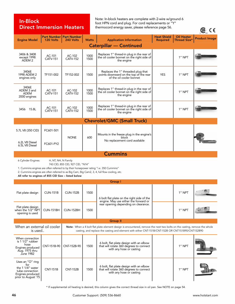
* If supplemental oil heating is desired, this column gives the correct thread size in oil pan. See NOTE on page 54.
46 Customer Support: (509) 536-8660 www.hotstart.com
In-BlockDirect Immersion Heaters
Note: In-block heaters are complete with 2-wire w/ground 6foot HPN cord and plug. For cord replacements or “Y”thermocord energy saver, please reference page 56.
Engine ModelPart Number
120 VoltsPart Number
240 Volts Watts Application InformationHeat Shield
RequiredOil Heater
Thread Size* Product Image
Caterpillar — Continued
3406 & 3408except 1998
ADEM 2
AC-101CATV-151
AC-102CATV-152
10001500
Replaces 1” thread-in plug in the rear ofthe oil cooler bonnet on the right side of
the engine1” NPT
3406E1998 ADEM 2engines only
TF151-002 TF152-002 1500Replaces the 1” threaded plug that
points downward on the top of the rearof the oil cooler bonnet
YES 1” NPT
3406E ADEM 3 and
ADEM 2000 engines
AC-101CATV-151
AC-102CATV-152
10001500
Replaces 1” thread-in plug in the rear ofthe oil cooler bonnet on the right side of
the engine1” NPT
3456 15.8L AC-101CATV-151
AC-102CATV-152
10001500
Replaces 1” thread-in plug in the rear ofthe oil cooler bonnet on the right side of
the engine 1” NPT
Chevrolet/GMC (Small Truck)
5.7L V8 (350 CID) FC601-501
NONE 600Mounts in the freeze plug in the engine’s
blockNo replacement cord available6.2L V8 Diesel
6.5L V8 Diesel FC601-PY2
Cummins6 Cylinder Engines: H, NT, NH, N Family
743 CID, 855 CID, 927 CID, “N14”1. Cummins engines are often referred to by their horsepower rating “i.e. 350 Cummins”2. Cummins engines are often referred to as Big Cam, Big Cam2, 3, 4, full flow cooling, etc.All refer to engines of 855 CID Size – listed below
Group I
Flat plate design CUN-151B CUN-152B 1500
6 bolt flat plate on the right side of theengine. May use either the forward orrear opening depending on clearance.
1” NPT
Flat plate designwhen the 1/2” NPT
opening is usedCUN-151BH CUN-152BH 1500 1” NPT
Group II
When an external oil cooleris used..
Note: When a 4 bolt flat plate element design is encountered, remove the next two bolts on the casting, remove the wholecasting, and replace the casting and element with either CNT-151B/CNT-152B OR CNT151B90/CNT152B90
When connection is 1 1/2” rubber
hoseEngines produced
Aug. 1975 thruJune 1982
CNT-151B-90 CNT-152B-90 15006 bolt, flat plate design with an elbowthat will rotate 360 degrees to connect
with any hose or casting1” NPT
Uses an “O” ringfor
the 1 1/4” watertube connection
Engines producedprior to August ‘75
CNT-151B CNT-152B 1500 6 bolt, flat plate design with an elbowthat will rotate 360 degrees to connect
with any hose or casting1” NPT
C US

47Customer Support: (509) 536-8660 www.hotstart.com
* If supplemental oil heating is desired, this column gives the correct thread size in oil pan. See NOTE on page 54.
In-BlockDirect Immersion Heaters
Note: In-block heaters are complete with 2-wire w/ground 6 footHPN cord and plug. For cord replacements or “Y” thermocordenergy saver, please reference page 56.
Engine ModelPart Number
120 VoltsPart Number
240 Volts Watts Application InformationHeat Shield
RequiredOil Heater
Thread Size* Product Image
Cummins — ContinuedGroup III
For industrialengines with holepattern reversed
CUN-151BREV CUN-152BREV 1500 Six bolt flat plate on the right side of the
block 1” NPT
Group IV
1998 and laterN14 Industrial PF151-002 PF152-002 1500 Six bolt flat plate on the right side of the
block 1” NPT
Additional Cummins Engine Models
Cummins A4 cyl & 6 cyl CUA-101F CUA-102F 1000 Inserts in any of the freeze plugs on right
side of engine. Element points down.
ISC/QSC 8.3LISL/QSL 9.0L DD8L-101 DD8L-102 1000 3/4” NPT threaded plug in the
right rear side of engine 22mm
L10, M11ISM CUL-151 CUL-152 1500 Inserts in the forward opening of the
heater casting on the right rear of block 1” NPT
QSB 3.9L, 5.9LISB 5.9 TF751-002 TF752-002 750 3/4” NPT threaded plug in the front
of the oil cooler casting 22mm
ISM/QSM 11.0LFlat Plate Design PF151-003 PF152-003 1500 Right rear. Replaces plate. 1” NPT
QSX, ISXSignature 600 PF151-004 PF152-004 1500 Mounts in the oval shaped plate on the
right side of the block 27mm
4BT 3.9L CUB-751FPCUB-101FP
CUB-752FPCUB-102FP
7501000
Inserts in any of the freeze plugs right side of engine
Check ExhaustRouting 22mm
6BT 5.9LCUB-751FPCUB-101FPCUB-151FP
CUB-752FPCUB-102FPCUB-152FP
75010001500
Inserts in any of the freeze plugs right side of engine
Check ExhaustRouting 22mm
6CT 8.3L CUC-151FP CUC-152FP 1500 Inserts in the freeze plugright rear of the block 22mm
Detroit Diesel
SERIES 104 cylinder
Phaser engines
PER-751FPPER-101FP
PER-752FPPER-102FP
7501000
Mounts in the 1-1/4” freeze plugopening on either side of the engine
SERIES 106 cylinder
Phaser enginesPER-151FP PER-152FP 1500 Mounts in the 1-1/2” freeze plug on the
right side of the engine
SERIES 30 DD8L-101 DD8L-102 1000 Mounts in the 3/4” NPT opening in theblock
C US
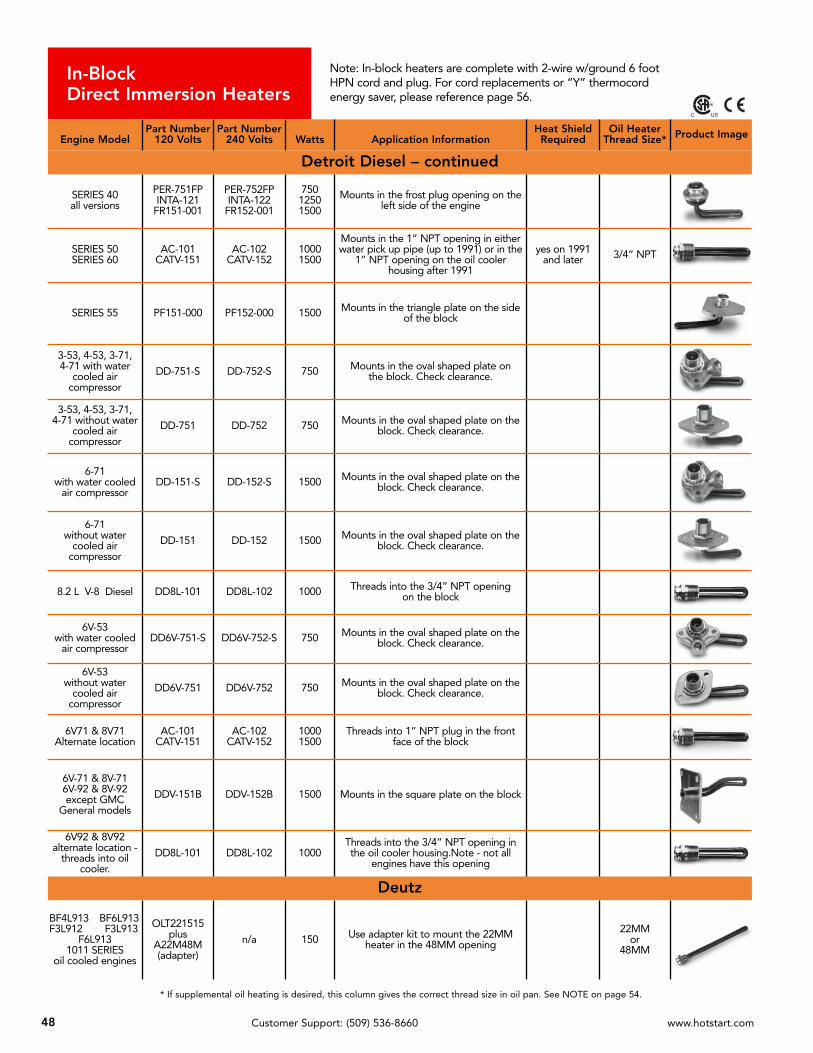
* If supplemental oil heating is desired, this column gives the correct thread size in oil pan. See NOTE on page 54.
48 Customer Support: (509) 536-8660 www.hotstart.com
In-BlockDirect Immersion Heaters
Note: In-block heaters are complete with 2-wire w/ground 6 footHPN cord and plug. For cord replacements or “Y” thermocordenergy saver, please reference page 56.
Engine ModelPart Number
120 VoltsPart Number
240 Volts Watts Application InformationHeat Shield
RequiredOil Heater
Thread Size* Product Image
Detroit Diesel – continued
SERIES 40all versions
PER-751FPINTA-121
FR151-001
PER-752FPINTA-122
FR152-001
75012501500
Mounts in the frost plug opening on theleft side of the engine
SERIES 50SERIES 60
AC-101CATV-151
AC-102CATV-152
10001500
Mounts in the 1” NPT opening in eitherwater pick up pipe (up to 1991) or in the
1” NPT opening on the oil coolerhousing after 1991
yes on 1991and later 3/4” NPT
SERIES 55 PF151-000 PF152-000 1500 Mounts in the triangle plate on the sideof the block
3-53, 4-53, 3-71, 4-71 with water
cooled aircompressor
DD-751-S DD-752-S 750 Mounts in the oval shaped plate onthe block. Check clearance.
3-53, 4-53, 3-71, 4-71 without water
cooled aircompressor
DD-751 DD-752 750 Mounts in the oval shaped plate on theblock. Check clearance.
6-71with water cooled
air compressorDD-151-S DD-152-S 1500 Mounts in the oval shaped plate on the
block. Check clearance.
6-71 without water
cooled aircompressor
DD-151 DD-152 1500 Mounts in the oval shaped plate on theblock. Check clearance.
8.2 L V-8 Diesel DD8L-101 DD8L-102 1000 Threads into the 3/4” NPT openingon the block
6V-53with water cooled
air compressorDD6V-751-S DD6V-752-S 750 Mounts in the oval shaped plate on the
block. Check clearance.
6V-53without water
cooled aircompressor
DD6V-751 DD6V-752 750 Mounts in the oval shaped plate on theblock. Check clearance.
6V71 & 8V71Alternate location
AC-101CATV-151
AC-102CATV-152
10001500
Threads into 1” NPT plug in the frontface of the block
6V-71 & 8V-716V-92 & 8V-92except GMC
General models
DDV-151B DDV-152B 1500 Mounts in the square plate on the block
6V92 & 8V92alternate location -
threads into oilcooler.
DD8L-101 DD8L-102 1000Threads into the 3/4” NPT opening inthe oil cooler housing.Note - not all
engines have this opening
Deutz
BF4L913 BF6L913F3L912 F3L913
F6L9131011 SERIES
oil cooled engines
OLT221515plus
A22M48M(adapter)
n/a 150 Use adapter kit to mount the 22MM heater in the 48MM opening
22MMor
48MM
C US

49Customer Support: (509) 536-8660 www.hotstart.com
* If supplemental oil heating is desired, this column gives the correct thread size in oil pan. See NOTE on page 54.
In-BlockDirect Immersion Heaters
Note: In-block heaters are complete with 2-wire w/ground 6 footHPN cord and plug. For cord replacements or “Y” thermocordenergy saver, please reference page 56.
Engine ModelPart Number
120 VoltsPart Number
240 Volts Watts Application InformationHeat Shield
RequiredOil Heater
Thread Size* Product Image
Deutz – continued
1012 — 4 & 6 cyl1013 — 4 cyl PF751-000 PF752-000 750 Mounts in the oval shaped plate opening
on the oil cooler casting
1013 6 cyl PF121-001 PF122-001 1250 Mounts in the oval shaped plate openingon the oil cooler casting
10156 & 8 cyl TL151-004 TL152-004 1500 Mounts in 30MM plug in water elbow on
front of the engine
2012 — 4 & 6 cyl PF751-002 PF752-002 750 Mounts in the oval shaped plate openingon the oil cooler casting
Ford
6.9L & 7.3L V-8diesels through
1993FC101-PY1 None 1000 Mounts in a freeze plug on the engine's
block. No replacement cord available.
7.3L V-8 dieselsfrom 1994 on
TF751-002 DD8L-101
TF752-002 DD8L-102
7501000
Mounts in the 3/4” NPT plug in theengine's block
Hino
3.8L, 5.8L, 6.0L,6.4L, 6.7L, W04C-T,
W06E, H06C-T,H07C-B
DD8L-101 DD8L-102 1000 Threads into 3/4” NPT openingin the block YES
Isuzu4BD1
6HE16BD1
6SA16BG1
TF401-501 NONE 400 Replaces 1” NPT plug in left rear ofengine
Iveco
NEF 4cylNEF 6 cyl PF751-001 PF752-001 750 Mount in either front or rear opening on
right side of engine block
John DeereWith 3/4” plug inthe back of the
block
JD3/4-101INJD3/4-151IN
JD3/4-102INJD3/4-152IN
10001500
3/4” NPT opening in the rear face of the block
checkExhaustrouting
With 1” plug in theback of the block
JD1-101INJD1-151IN
JD1-102INJD1-152IN
10001500
1” NPT opening in the rear face of the block
With 1 5/8”opening on the sideof the water jacket
JDS-101 JDS-102 10001-5/8” threaded opening on the side of
the block in the water distributionchannel
C US
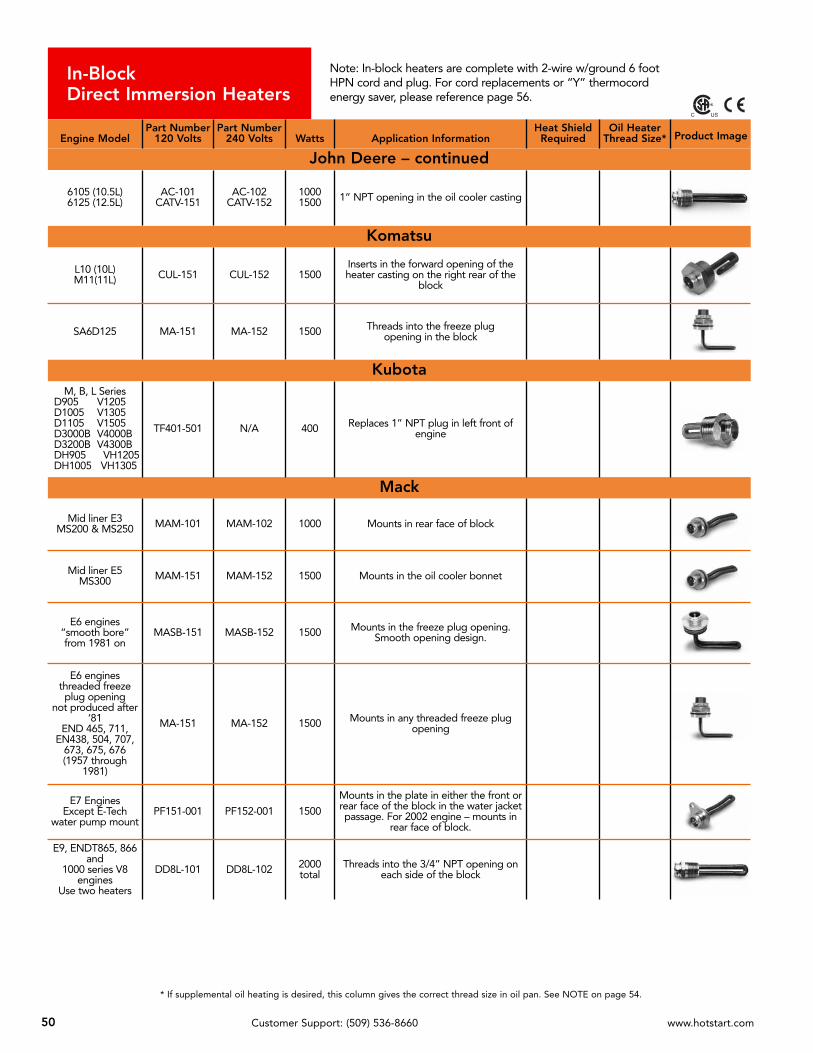
* If supplemental oil heating is desired, this column gives the correct thread size in oil pan. See NOTE on page 54.
50 Customer Support: (509) 536-8660 www.hotstart.com
In-BlockDirect Immersion Heaters
Note: In-block heaters are complete with 2-wire w/ground 6 footHPN cord and plug. For cord replacements or “Y” thermocordenergy saver, please reference page 56.
Engine ModelPart Number
120 VoltsPart Number
240 Volts Watts Application InformationHeat Shield
RequiredOil Heater
Thread Size* Product Image
John Deere – continued
6105 (10.5L)6125 (12.5L)
AC-101CATV-151
AC-102CATV-152
10001500 1” NPT opening in the oil cooler casting
Komatsu
L10 (10L)M11(11L) CUL-151 CUL-152 1500
Inserts in the forward opening of theheater casting on the right rear of the
block
SA6D125 MA-151 MA-152 1500 Threads into the freeze plug opening in the block
KubotaM, B, L Series
D905 V1205D1005 V1305D1105 V1505D3000B V4000BD3200B V4300BDH905 VH1205DH1005 VH1305
TF401-501 N/A 400 Replaces 1” NPT plug in left front ofengine
Mack
Mid liner E3MS200 & MS250 MAM-101 MAM-102 1000 Mounts in rear face of block
Mid liner E5MS300 MAM-151 MAM-152 1500 Mounts in the oil cooler bonnet
E6 engines“smooth bore”from 1981 on
MASB-151 MASB-152 1500 Mounts in the freeze plug opening.Smooth opening design.
E6 enginesthreaded freezeplug opening
not produced after‘81
END 465, 711,EN438, 504, 707,
673, 675, 676(1957 through
1981)
MA-151 MA-152 1500 Mounts in any threaded freeze plugopening
E7 EnginesExcept E-Tech
water pump mountPF151-001 PF152-001 1500
Mounts in the plate in either the front orrear face of the block in the water jacketpassage. For 2002 engine – mounts in
rear face of block.
E9, ENDT865, 866and
1000 series V8engines
Use two heaters
DD8L-101 DD8L-102 2000total
Threads into the 3/4” NPT opening oneach side of the block
C US

51Customer Support: (509) 536-8660 www.hotstart.com
* If supplemental oil heating is desired, this column gives the correct thread size in oil pan. See NOTE on page 54.
In-BlockDirect Immersion Heaters
Note: In-block heaters are complete with 2-wire w/ground 6 footHPN cord and plug. For cord replacements or “Y” thermocordenergy saver, please reference page 56.
Engine ModelPart Number
120 VoltsPart Number
240 Volts Watts Application InformationHeat Shield
RequiredOil Heater
Thread Size* Product Image
MAND2840D2842D2848
PF121-003 PF122-003 1250 Replace oval shaped plate in lower waterpipe on right side of engine
D2866D2876 PF151-006 PF152-006 1500
Replace 3 bolt plate on left side ofengine. May require adapter if 3 boltopening is not available on engine.
Consult customer service.
Mercedes Benz
MBE904MBE906 PF101-001 PF102-001 1000 Replace frost plug in rear of engine on
right side YES
Massey Ferguson3 cylinder4 cylinder6 cylinder
PER-751FPPER-101FP
PER-752FPPER-102FP
7501000
Mounts in any of the 1-1/4” freeze plugopenings in the engine
Navistar/International
V800 (796 CID) AC-101CATV-151
AC-102CATV-152
10001500
Threads into a 1” NPT opening in the oil cooler bonnet
INLINE 6CYLINDER
— all series —312, 360, 414, 436,
466 & 530
PER-751FPINTA-121
FR151-001
PER-752FPINTA-122
FR152-001
75012501500
Mounts in the frost plug on the left sideof the engine.
Fits all series of these engines.
6.9L & 7.3LV8 diesels
through 1993
FC101-PY1or
FC601-501None
1000
600
No replacement cord available. Mountsin a freeze plug above starter
7.3L & T444all series DD8L-101 DD8L-102 1000 3/4” NPT threaded opening in the block
9.0L — V8 diesel INT9-101F INT9-102F 1000 Mounts in a freeze plug
Oliver
ALL EXCEPT 1265,1365 & 1900
TF751-002DD8L-101
TF752-002DD8L-102
7501000
Threads into a 3/4” NPT opening in the block
Onan — See Cummins “A” SeriesPerkins
3.1524.2366.354
PER-751FPPER-101FP
PER-752FPPER-102FP
7501000
Mounts in the 1-1/4” freeze plugopening on the right side of the engine
103.15104.22404.22
FP531-003 FP532-003 530 Mounts in left front freeze plug
C US
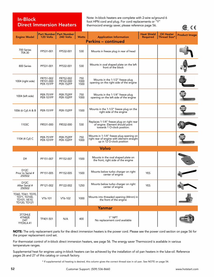
* If supplemental oil heating is desired, this column gives the correct thread size in oil pan. See NOTE on page 54.
52 Customer Support: (509) 536-8660 www.hotstart.com
In-BlockDirect Immersion Heaters
Note: In-block heaters are complete with 2-wire w/ground 6foot HPN cord and plug. For cord replacements or “Y”thermocord energy saver, please reference page 56.
NOTE: The only replacement parts for the direct immersion heaters is the power cord. Please see the power cord section on page 56 forthe proper replacement cord set.
For thermostat control of in-block direct immersion heaters, see page 56. The energy saver Thermocord is available in varioustemperature ranges.
Supplemental heat for engines using in-block heaters can be achieved by the installation of oil pan heaters in the lube-oil. Referencepages 26 and 27 of this catalog or consult factory.
Engine ModelPart Number
120 VoltsPart Number
240 Volts Watts Application InformationHeat Shield
RequiredOil Heater
Thread Size*Product Image
Perkins – continued
700 Series704.30 FP531-001 FP532-001 530 Mounts in freeze plug in rear of head
800 Series PF531-001 PF532-001 530 Mounts in oval shaped plate on the leftfront of the block
1004 (right side)FR751-002FR101-000PER-151FP
FR752-002FR102-000PER-152FP
75010001500
Mounts in the 1-1/2” freeze plugopening on the right side of the engine
1004 (left side) PER-751FPPER-101FP
PER-752FPPER-102FP
7501000
Mounts in the 1-1/4” freeze plugopening on the left side of the engine
1006 (6 Cyl) A & B PER-151FP PER-152FP 1500 Mounts in the 1-1/2” freeze plug on theright side of the engine
1103C FR531-000 FR532-000 530Replaces 1-1/4” freeze plug on right rear
of engine. Element should pointtowards 1 O-clock position.
1104 (4 Cyl) C PER-751FPPER-101FP
PER-752FPPER-102FP
7501000
Mounts in 1-1/4” freeze plug opening onright rear of engine with element straight
up in 12 O-clock position
Volvo
D9 PF151-007 PF152-007 1500 Mounts in the oval shaped plate onthe front, right side of the engine
D12CPrior to Serial #
250502PF151-005 PF152-005 1500 Mounts below turbo charger on right
center of engine YES
D12CAfter Serial #
250502PF121-002 PF122-002 1250 Mounts below turbo charger on right
center of engine YES
TD60, TD61, TD70,TD71, TD100,TD101, VE10,TD120, TD121
VT6-101 VT6-102 1000 Mounts into threaded opening (44mm) inthe front of the engine
Yanmar 3T72HLE4TN82E
D4TYYDXL4.41
TF401-501 N/A 400 1” NPTNo replacement cord available
C US

53Customer Support: (509) 536-8660 www.hotstart.com
Heater InstallationInstructions for:In-block direct immersion heatersPlease refer to specific instructions that accompany heater.
THREADED PLUG TYPE HEATERS
PLATE TYPE HEATERS
FREEZE (CORE) PLUG TYPE HEATERS
Please follow these steps to ensure proper operation of yourHOTSTART in-block heater.
1. Align cord with pins on the heater and press the cord into theheater. Place clamp around cord & heater. DO NOT PLUG INHEATER YET!
2. Route the cord, keeping away from hot or moving surfaces.
3. Re-fill the cooling system. Run engine until engine thermostatopens and continue running for another 20 minutes to eliminateair.
4. Stop engine and let cool. Check for leaks. Check coolant level.
5. Plug heater into power supply and test for proper operation.Block should feel warm near heater.
A.Drain the cooling system.
B.Remove the recommendedplug. (See instructions withheater)
C.Apply teflon tape to pipethreads or grease to O ring.
D.Thread heater into engine.
A.Drain the cooling system.
B.Remove the recommendedplate. (See instructions withheater)
C.Clean the gasket area.
D. Apply gasket sealant to plateand engine surfaces.
E. Insert heater into engine.Tighten bolts.
Please follow these steps to ensure proper operation of yourHOTSTART in-block heater.
1. Align cord with pins on the heater and press the cord into theheater. Place clamp around cord & heater. DO NOT PLUG INHEATER YET!
2. Route the cord, keeping away from hot or moving surfaces.
3. Re-fill the cooling system. Run engine until enginethermostat opens and continue running for another 20minutes to eliminate air.
4. Stop engine and let cool. Check for leaks. Check coolant level.
5. Plug heater into power supply and test for proper operation.Block should feel warm near heater.
A.Drain the cooling system.
B.Remove the recommendedcore plug. (See instructionswith heater)
C.Clean, smooth and dry coreplug opening.
D.If retaining ring style, apply alight coat of grease to the Oring and core plug opening. Ifpress-in style, apply a light coatof high-temperature, high-strength retaining compound(Loctite 640 recommended).
E. Insert heater into engine andposition properly. Push theheater into the engine byhand, then tap in using asuitable tool until flange iseven with engine block.
Please follow these steps to ensure proper operation of yourHOTSTART in-block heater.
1. Align cord with pins on the heater and press the cord into theheater. Place clamp around cord & heater. DO NOT PLUG INHEATER YET!
2. Route the cord, keeping away from hot or moving surfaces.
3. Re-fill the cooling system. Run engine until engine thermostatopens and continue running for another 20 minutes to eliminateair.
4. Stop engine and let cool. Check for leaks. Check coolant level.
5. Plug heater into power supply and test for proper operation.Block should feel warm near heater.
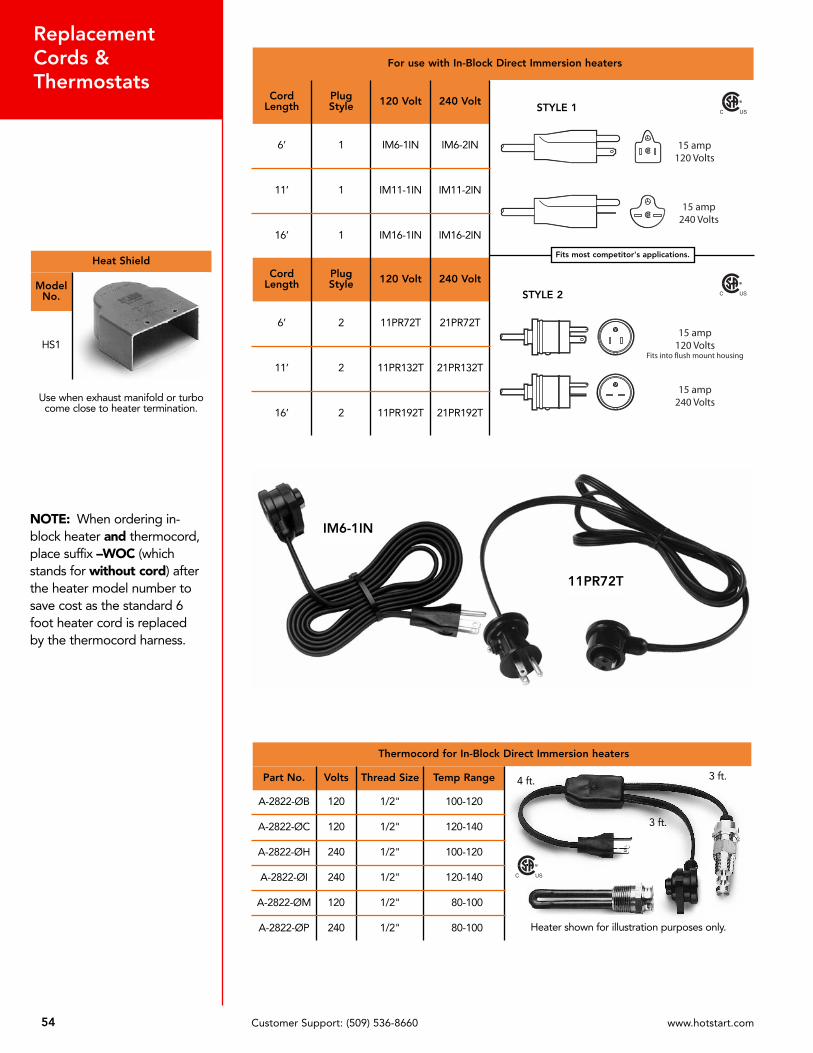
54 Customer Support: (509) 536-8660 www.hotstart.com
ReplacementCords &Thermostats
Thermocord for In-Block Direct Immersion heaters
Part No. Volts Thread Size Temp Range
A-2822-ØB 120 1/2" 100-120
A-2822-ØC 120 1/2" 120-140
A-2822-ØH 240 1/2" 100-120
A-2822-ØI 240 1/2" 120-140
A-2822-ØM 120 1/2" 80-100
A-2822-ØP 240 1/2" 80-100
4 ft.
3 ft.
3 ft.
NOTE: When ordering in-block heater and thermocord,place suffix –WOC (whichstands for without cord) afterthe heater model number tosave cost as the standard 6foot heater cord is replacedby the thermocord harness.
Heater shown for illustration purposes only.
C US
Heat Shield
ModelNo.
HS1
Use when exhaust manifold or turbocome close to heater termination.
For use with In-Block Direct Immersion heaters
CordLength
PlugStyle 120 Volt 240 Volt
6’ 1 IM6-1IN IM6-2IN
11’ 1 IM11-1IN IM11-2IN
16’ 1 IM16-1IN IM16-2IN
CordLength
PlugStyle 120 Volt 240 Volt
6’ 2 11PR72T 21PR72T
11’ 2 11PR132T 21PR132T
16’ 2 11PR192T 21PR192T
STYLE 1
STYLE 2
C US
C US
11PR72T
IM6-1IN
Fits most competitor's applications.

55Customer Support: (509) 536-8660 www.hotstart.com
Flush Mount Kits &Accessories
Other Accessories
Flush mount kits for tank heaters
ModelNumber Volts Amps For Heater with
Wattage of:Kits include:
Recessed malereceptacle with 6’ cord(no female connectors),hinged flip cover and
female connector
FM15120 120 15 500 to 1800
FM15240 240 15 500 to 3000
FM20120 120 20 2000 to 2250
3.5.78125
.3125
Recessed Male Receptacle – with 6 ft. cord (no female connectors)
Model Number Volts Amps
RM5-15RM6-15RM5-2ØRM6-2Ø
120240120240
15152020
Female Connector Only - for extension cords
Model Number Volts Amps
FM1G2ØAFM2G2ØA
120240
15/2015/20
Hinged Cover Only
Model Number Description3.25 .78125
3.3125*FC-KHFC-KH-C
Black/Kim LogoChrome/Kim Logo
*Note: Standard with kit
Plug Housing
Model Number
A-2223-PH
Flush mount kits for In-Block Direct Immersion heaters
ModelNumber120 Volt
ModelNumber240 Volt
CordLength
PlugStyle
Kits include: 11PR- style cord
(shown on page 56),recessed male
receptacle and hingedflip cover
IM6-1IN-FM IM6-2IN-FM 6’ 2
IM11-1IN-FM IM11-2IN-FM 11’ 2
IM16-1IN-FM IM16-2IN-FM 16’ 2
3.5.78125
.3125
C US
C US
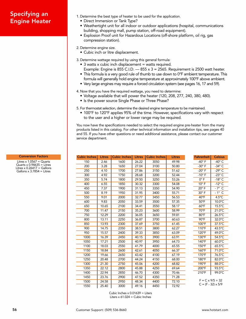
56 Customer Support: (509) 536-8660 www.hotstart.com
Specifying anEngine Heater
Cubic Inches x 0.01639 = LitersLiters x 61.024 = Cubic Inches
F = C x 9/5 + 32C = (F - 32) x 5/9
1. Determine the best type of heater to be used for the application.• Direct Immersion or Tank Type?• Weathertight unit for all indoor or outdoor applications (hospital, communications
building, shopping mall, pump station, off-road equipment).• Explosion Proof unit for Hazardous Locations (off-shore platform, oil rig, gas
compression station).
2. Determine engine size.• Cubic inch or litre displacement.
3. Determine wattage required by using this general formula:• 3 watts x cubic inch displacement = watts required.
Example: Engine is 855 C.I.D. — 855 x 3 = 2565. Requirement is 2500 watt heater.• This formula is a very good rule of thumb to use down to 0°F ambient temperature. This
formula will generally hold engine temperature at approximately 100°F above ambient.• Very large engines may require a forced circulation system (see pages 16, 17 and 59).
4. Now that you have the required wattage, you need to determine:• Voltage available that will power the heater (120, 208, 277, 240, 380, 480).• Is the power source Single Phase or Three Phase?
5. For thermostat selection, determine the desired engine temperature to be maintained.• 100°F to 120°F applies 95% of the time. However, specifications vary with respect
to the user and a higher or lower range may be required.
You now have the specifications needed to select the required engine pre-heater from the manyproducts listed in this catalog. For other technical information and installation tips, see pages 40and 55. If you have other questions or need additional assistance, please contact our customerservice department.
Conversion Factors
Litres x 1.0567 = QuartsQuarts x 0.94635 = LitresLitres x 0.26417 = GallonsGallons x 3.7854 = Litres
Cubic Inches Litres Cubic Inches Litres Cubic Inches Litres
150 2.46 1600 26.22 3050 49.98200 3.28 1650 27.04 3100 50.80250 4.10 1700 27.86 3150 51.62300 4.92 1750 28.68 3200 52.44350 5.74 1800 29.50 3250 53.26400 6.55 1850 30.32 3300 54.08450 7.37 1900 31.13 3350 54.90500 8.19 1950 31.95 3400 55.71550 9.01 2000 32.77 3450 56.53600 9.83 2050 33.59 3500 57.35650 10.65 2100 34.41 3550 58.17700 11.47 2150 35.23 3600 58.99750 12.29 2200 36.05 3650 59.81800 13.11 2250 36.87 3700 60.63850 13.93 2300 37.69 3750 61.45900 14.75 2350 38.51 3800 62.27950 15.57 2400 39.33 3850 63.091000 16.39 2450 40.15 3900 63.911050 17.21 2500 40.97 3950 64.731100 18.03 2550 41.79 4000 65.551150 18.84 2600 42.61 4050 66.371200 19.66 2650 43.42 4100 67.191250 20.48 2700 44.24 4150 68.001300 21.30 2750 45.06 4200 68.821350 22.12 2800 45.88 4250 69.641400 22.94 2850 46.70 4300 70.461450 23.76 2900 47.52 4350 71.281500 24.58 2950 48.34 4400 72.101550 25.40 3000 49.16 4450 72.92
Fahrenheit Celsius
-40° F -40° C-30° F -34° C-20° F -29° C-10° F -23° C0° F -18° C10° F -12° C20° F - 7° C30° F - 1° C40°F 4.5°C50°F 10.0°C60°F 15.5°C70°F 21.0°C80°F 26.5°C90°F 32.0°C100°F 37.5°C110°F 43.5°C120°F 49.0°C130°F 54.5°C140°F 60.0°C150°F 65.5°C160°F 71.0°C170°F 76.5°C180°F 82.0°C190°F 88.0°C200°F 93.5°C210°F 99.0°C
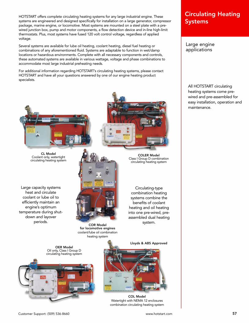
57Customer Support: (509) 536-8660 www.hotstart.com
Large engineapplications
Circulating HeatingSystems
HOTSTART offers complete circulating heating systems for any large industrial engine. Thesesystems are engineered and designed specifically for installation on a large generator, compressorpackage, marine engine, or locomotive. Most systems are mounted on a steel plate with a pre-wired junction box, pump and motor components, a flow detection device and in-line high-limitthermostats. Plus, most systems have fused 120 volt control voltage, regardless of appliedvoltage.
Several systems are available for lube oil heating, coolant heating, diesel fuel heating orcombinations of any aforementioned fluid. Systems are adaptable to function in wet/damplocations or hazardous environments. Complete with all necessary components and controls,these automated systems are available in various wattage, voltage and phase combinations toaccommodate most large industrial preheating needs.
For additional information regarding HOTSTART’s circulating heating systems, please contactHOTSTART and have all your questions answered by one of our engine heating productspecialists.
COR Modelfor locomotive engines
coolant/lube oil combinationheating system
Large capacity systemsheat and circulate
coolant or lube oil toefficiently maintain an
engine’s optimumtemperature during shut-
down and layoverperiods.
CL ModelCoolant only, watertight
circulating heating system
OER ModelOil only, Class I Group D
circulating heating system
Circulating-typecombination heatingsystems combine thebenefits of coolant
heating and oil heatinginto one pre-wired, pre-assembled dual heating
system.
COLER ModelClass I Group D combination
circulating heating system
COL ModelWatertight with NEMA 12 enclosures
combination circulating heating system
Lloyds & ABS Approved
All HOTSTART circulatingheating systems come pre-wired and pre-assembled foreasy installation, operation andmaintenance.

www.cadel.com