Production system of composite side panel for urban city …562082/FULLTEXT01.pdf5 Master of Science...
88
Production system of composite side panel for urban city car LISA NÄÄS Master of Science Thesis Stockholm, Sweden 2011
Transcript of Production system of composite side panel for urban city …562082/FULLTEXT01.pdf5 Master of Science...

Production system of composite side panel for urban city car
LISA NÄÄS
Master of Science Thesis Stockholm, Sweden 2011

2

3
Production system of composite side panel for urban city car
Lisa Nääs
Master of Science Thesis MMK 2011:069 {IDE 080} KTH Industrial Engineering and Management
Machine Design SE‐100 44 STOCKHOLM

4

5
Master of Science Thesis MMK 2011:069 {IDE 080}
Production system of composite side panel for urban city car
Lisa Nääs
Approved
Examiner
Carl Michael Johannesson
Supervisor
Anna Hedlund Åström Commissioner
Team H2politO
Contact person
Massimiliana Carello
Abstract
A theoretical study of possible production systems for future production of a side panel made of composite material and belonging to an urban city car has been carried out. The study has taken place within Team H2politO at the Polytechnic University of Turin in Italy. Three different production volumes have been analyzed considering dimensional limits, economy, production rate, machinery, material and environment. These have been set to 1 000, 10 000 and 100 000 components/year. Previous studies within the field have been analyzed, combined and used as a basis in order to arrive at an appropriate choice of production methodology regarding the different production volumes. A comparison with production methods for the side panel if it would have been manufactured with aluminum has been made and the profitability of composite production has been evaluated. Production‐ and material data have been collected from the software CES EduPack and revised based on study visits and interviews. The side panel has thereafter been edited and dimensioned in terms of recommendations for optimization of a future production. Modeling has been made using Autodesk Alias Design, Photoshop and Edraw Max. Furthermore, overview plan drawings of production plants have been made.
The study has given results in terms of recommendations and requirement specifications for future projects within the field. For continued studies about the profitability of composite production, an accurate study about different composite materials including tests of material characteristics is suggested. A detailed plan of the production plant with exact dimensions and technical data for optimization of production time is also recommended. In addition to this, it is essential to develop a better assembly system between the side panel and the roof panel as well as investigate the possibility of a more profitable production method for medium‐ to large scale production of composite details.

6

7
Examensarbete MMK 2011:069 {IDE 080}
Produktionssystem av komposit sidopanel på en stadsbil
Lisa Nääs
Godkänt
Examinator
Carl Michael Johannesson
Handledare
Anna Hedlund Åström
Uppdragsgivare
Team H2politO
Kontaktperson
Massimiliana Carello
Sammanfattning
En teoretisk studie av möjliga produktionssystem för framtida produktion av en sidopanel i kompositmaterial på en stadsbil har utförsts. Studien har ägt rum inom Team H2politO på Tekniska Högskolan i Turin i Italien. Tre olika produktionsvolymer har analyserats med avseende på dimensionsgränser, ekonomi, produktionstid, maskineri, material och miljö. Dessa har valts till 1 000, 10 000 respektive 100 000 komponenter/år. Tidigare studier inom ämnet har analyserats, kombinerats och använts som underlag för att komma fram till lämpligt val av produktionsmetod för de olika produktionsvolymerna. En jämförelse med produktionsmetoder för sidopanelen om den skulle ha varit tillverkad i aluminium har gjorts och lönsamheten av komposittillverkning för komponenten har utvärderats. Produktions‐ och materialdata har hämtats ur datorprogrammet CES EduPack samt reviderats utifrån studiebesök och intervjuer. Sidopanelen har därefter med hjälp av rekommendationer anpassats och dimensionerats för att optimera en framtida produktion. Modellering har skett i datorprogrammet Autodesk Alias Design, Photoshop och Edraw Max. Ytterligare har översiktsritningar på produktionsanläggningar gjorts.
Studien har gett resultat i form av rekommendationer och kravspecifikationer för framtida projekt inom området. För fortsatta studier inom lönsamheten av kompositproduktion föreslås en noggrannare analys av olika kompositmaterial samt tester av materialegenskaper. En detaljritning av produktionsanläggningen med mer exakta mått och tekniska data för optimering av produktionstid rekommenderas också. Utöver dessa förslag, är det nödvändigt att utveckla en bättre lösning på montering mellan sidopanelen och takpanelen samt en mer lönsam produktionsmetod för medel‐ till massproduktion av kompositdetaljer.

8

9
Table of Contents
Chapter 1. Introduction and Background .................................................................................... 11
1.1. A Short Introduction to Team H2politO ................................................................................ 11
1.2. Purpose .................................................................................................................................. 13
1.3. Method .................................................................................................................................. 14
Chapter 2. Case Study of the Prototype Production of the Side Panel ....................................... 17
2.1. Background ............................................................................................................................ 17
2.2. Prototype Production ............................................................................................................ 18
2.3. Summary and Observations .................................................................................................. 23
2.4. Recommendations................................................................................................................. 23
2.5. Conclusion ............................................................................................................................. 23
Chapter 3. Case Study of the Design of the Side Panel ............................................................... 25
3.1. Background ............................................................................................................................ 25
3.2. Dimensional Limits ................................................................................................................ 26
3.3. Manufacturing and Assembly ................................................................................................ 27
3.4. Aero Dynamics ....................................................................................................................... 30
3.5. Overall Summary and Conclusion ......................................................................................... 32
Chapter 4. Bench Marking – an Introduction to Composite Production Systems ...................... 33
4.1. Background ............................................................................................................................ 33
4.2. Flax Fiber ............................................................................................................................... 33
4.3. Composite Production ........................................................................................................... 34
4.4. Recommendations and Conclusion ....................................................................................... 41
Chapter 5. Composite Production with respect to the Side Panel .............................................. 43
5.1. Background ............................................................................................................................ 43
5.2. Dimensional Limits ................................................................................................................ 43
5.3. Economical Characteristics .................................................................................................... 47
5.4. Production Rate ..................................................................................................................... 51
5.5. Overall Summary and Conclusion ......................................................................................... 52
Chapter 6. Metal Production with Respect to the Composite Production of the Side Panel ..... 54
6.1. Background ............................................................................................................................ 54
6.2. An Introduction to Aluminum Production ............................................................................. 54
6.3. Dimensional Limits ................................................................................................................ 55
6.4. Economical Characteristics .................................................................................................... 56
6.5. Production Rate ..................................................................................................................... 58

10
6.6. Overall Summary and Conclusion ......................................................................................... 58
Chapter 7. Proposal of Medium to Large Scale Composite Production of the Side Panel .......... 60
7.1. Background ............................................................................................................................ 60
7.2. Machinery, Equipment and Plant Lay‐out ............................................................................. 60
7.3. Manufacturers ....................................................................................................................... 63
7.4. Environment and Life Cycle ................................................................................................... 66
7.5. Overall Summary and Conclusion ......................................................................................... 67
Chapter 8. Recommended Future Projects and Requirement Specifications ............................. 68
8.1. Assembly System ................................................................................................................... 68
8.2. Material Study ....................................................................................................................... 68
8.3. Plant Lay‐out .......................................................................................................................... 69
8.4. Recycling ................................................................................................................................ 70
Chapter 9. Discussion and Conclusions ....................................................................................... 72
Bibliography ........................................................................................................................................... 74
Appendix 1 – Interviews ........................................................................................................................ 76
Appendix 2 – Data Sheet of FlaxPreg .................................................................................................... 80
Appendix 3 – Data Sheet of Aluminum ................................................................................................. 82
Appendix 4 – Physical Attributes ........................................................................................................... 84
Appendix 5 – Economical attributes ..................................................................................................... 86
Appendix 6 – Press Data Sheet, Dieffenbacher ..................................................................................... 88

11
Chapter 1. Introduction and Background A theoretical study of possible production systems for future composite production of the side panel of an urban city car is under development at the Polytechnic University of Turin in Italy. The development takes place as part of a student project were students within different fields of study amplify and improve different parts of the car that at the end affiliate a manufacturing base for the entire car. A prototype of the car is built and the results are analyzed and tested for improvement.
This master thesis took place within Team H2politO, subdivision XAM ‐ a team whose aim is to improve the performance of the low energy consumption urban city vehicle XAM that is illustrated in Figure 1.1.
Figure 1.1. XAM ‐ a low energy consumption vehicle1
1.1. A Short Introduction to Team H2politO Team H2politO was founded in 2007 by 13 engineering students within different fields of expertise at the Polytechnic University of Turin by the help of Eng. Cozzari and the Faculty Advisor Eng. Carello. In 2011, the number of team members had increased to approximately 45 students [1]. Figure 1.2 illustrates part of the team outside of the Polytechnic University of Turin in July 2011.
Figure 1.2. The team H2PolitO outside of the Polytechnic University of Turin
2
The team is divided into two subdivisions – XAM and IDRA – whose prototype data is listed on the following page [2].
1 Figure from report: Team H2politO, Urban Concept 534: Technical Innovation Award, page 2 [2011.06.22] 2 Figure from website: Facebook, Team H2politO, URL: http://www.facebook.com [2011‐08‐15]

12
XAM – Figure 1.1 – is a prototype of an urban vehicle with low energy consumption • Length: 2800 mm
• Height: 1280 mm
• Width: 1300 mm
• Mass: 190 kg
• Power: 1 kW
• Propulsion: parallel hybrid
• Storage energy type: Ultra cap
• Motor: internal combustion engine + electric motor
• Body: natural fiber composites – FlaxPreg (epoxy resin and flax fiber)
• Human interface: embedded system + LCD screen
IDRA – Figure 1.3 – is a prototype of a competition vehicle with low energy consumption • Propulsion: hydrogen fuel cell (1 kW)
• Motor: one brushed electric motor (200 W)
• Transmission: cogwheels with direct engaging
• Electronics: digital engine control
• Tank: hydrogen cylinder (200 bars)
• Body: carbon fiber monocoque
• Mass: 38 kg
Figure 1.3. IDRA3
“The Team work and the prototypes can be considered as a business laboratory in which it is necessary to have the right balance of technical and managerial capabilities. Therefore, within H2politO, the technological competencies concerning the prototypes/products and the organizational skills are both developed.” [3]
Figure 1.4 shows the different areas of expertise (educational paths) vs. the management and organization of Team H2politO for the development of the innovative prototypes XAM and IDRA.
3 Figure from website: Politecnico di Torino, Idra, URL: http://srvh2polito.polito.it/en/prototypes.html [2011.06.22]

Figure 1.4.
1.2. The purpmethods opossibilitymetal proof the desrespect to
• D
• M
• Ae
The smallthrough atook placcomponen
• D
• Ec
• Pr
After the chosen. Aout were s
4 Figure from
. The different a
Purposeose of the tof the side pay with respectduction systesign of the sido:
imensional lim
Manufacturing
ero dynamics
scale produc case study. Tce in 2011. nts/year – we
imensional lim
conomical cha
roduction rat
analysis, posA proposal of subsequently
website: Politecni
areas of expertisfor the develop
e thesis was toanel of the out to the manuems for car code panel wer
mits
g and assemb
s
ction – up toThis was baseA possible
ere on the oth
mits
aracteristics
e
ssible producmachinery, ey to be compl
ico di Torino, Team
se (educational pment of the inn
o investigateuter body of tual method usomponent prre thereafter
ly
o 1 000 comped on the mamedium to
her hand ana
ction systemsequipment aneted conside
m H2politO, URL: h
13
paths) vs. the mnovative protot
e the possibithe urban citysed for its prooduction. Somto be given i
ponents/year anufacturing oo large scallyzed with re
s for mediumnd manufacturing the life c
http://srvh2polito
management andtypes XAM and I
ility of differy car XAM anototype prodme recommen order to fa
– of the sideof the protote productiospect to:
m to large scurers of thesecycle of the si
.polito.it/en/team
d organization oIDRA4
rent composnd compare auction as welendations for cilitate the p
e panel was type of the sidn – 10 000
cale productioe including a de panel.
m/who‐we‐are.htm
of Team H2politO
site productiond analyze thll as to possibimprovemen
production wi
to be analyzede panel whicand 100 00
on were to bbasic plant la
ml [2011.06.22]
O
on his ble nts th
ed ch 00
be ay‐

14
The considered material for the side panel in all of the above mentioned analysis of composite material production was kept the same as the material used for the prototype production of the urban city car XAM. The reason was to be able to compare the medium to mass scale production to the already made small scale production. The material was:
• FlaxPreg – thermosetting epoxy resin reinforced with flax fiber.
A study of a possible metal production system was made for the purpose of getting an overview of the differences and similarities of metal production compared to composite production. For the study of possible metal production systems, the material was chosen after a recommendation by Professor Settineri [4] and thereby set to:
• Aluminum Al 2024.
Additional reasons for choosing Al 2024 is its properties of high damage tolerance and low density making it a popular alloy for automotive and aerospace production.
1.3. Method The project methodology was carried out in steps, the different steps being presented and explained below. After every step a conclusion and recommendations were to be presented.
Step 1: Case Study – Prototype Production of the Side Panel of XAM a) Case study of the prototype production system used for the production of the side panel of
XAM in 2011, also considering its surface finish through interviews and a study visit. b) A theoretical material study of the physical and mechanical characteristics of the material
used for the production of the side panel through literature research. c) Design study of the side panel through interviews.
Step 2: Bench Marking – Production Systems a) To do a bench marking of possible composite production systems for future medium to large
scale production of the side panel in the course of literature studies. b) To do a general bench marking of possible production systems for the current production of
aluminum car components including a study of the characteristics of the material Al 2024 through literature studies.
Step 3: Choose Suitable Systems for Different Production Volumes considering a) Dimensional limits b) Economical characteristics c) Production rate
Step 4: Investigate the Producibility of the Side Panel of XAM a) Investigation of the producibility of the side panel with respect to the chosen production
systems and give recommendations of possible changes in design of the side panel of XAM for facilitating its future production.
b) Choosing possible material, machinery and equipment manufacturers for the production of the side panel through literature studies and recommendations by team members.
c) Considering the life cycle of the side panel.

Step 5: Ma) An
m
When havwere givepresentat
Figure 1.5showing tsimultaneprocessesanalysis an
5 Producer: LisEdraw Max: v
Metal Producnalyze the ch
methods and c
ving carried on. Documention of the pro
5 gives an ovthat the benceously but se for investigand recommen
sa Nääs. Student –version Professiona
ction hosen systemcompare poss
out all of the tation was keoject was held
verview of thch marking oparately in oating the prondations to th
Figure 1.5. O
– Design and Prodal 5.2, 2010
s for compossible advantag
steps 1 – 5, pt throughoud the 20th of D
he methodolof the procesorder to lateroducibility of he design of t
Overview of the
uct Realization. KT
15
site productioges and disad
recommendaut the projectDecember 20
logy of the pss and the car be tied togthe side panthe side pane
methodology u
TH Royal Institute
on with respedvantages.
ations for futu and a report011 at KTH Ro
project in thease study of gether when nel. Thereafteel were made
used for the thes
of Technology [20
ect to the me
ure studies at was writtenoyal Institute
e form of a the side panchoosing theer, the proce.
sis5
011], Software use
etal productio
nd conclusio. To concludeof Technolog
block diagranel were made best suitabess design, co
ed to create Figure
on
ns e a gy.
am de ble ost
e:

16

Chap
A case stunderstanprocedureproductiocomponenwith respe
2.1. The body products oautoclave interview company,
The entireand assemput the inwill not bmanufactu
6 PhotographeProduct RealiEdraw Max: v7 Producer: LisEdraw Max: v
pter 2.
udy of the pnding of proe with recomn is here dents/year. Theect to the tim
Backgroof the protoof composite molding andwith one o go to the firs
e production mbly – accordterest of the e additionallyuring of the m
er: Roozbeh Hashezation. KTH Royal version Professionasa Nääs. Student –version Professiona
Case Pane
production ofototype compmmendationsfined as a sme process usedme of product
Figure 2
ound otype of the materials. Thd is describedof the emplost interview in
process canding to Figurestudy on they analyzed. Tmold) and sur
Figure 2.2. A b
emi. Student – AutInstitute of Technal 5.2, 2010 – Design and Prodal 5.2, 2010
Study of el f the side paposite produ for future mall scale prd for the prodion and numb
2.1. The side pa
urban vehiclhe method usd below baseoyees [5]. Fon Appendix 1
be divided ie 2.2. After a e production –The productiorface finishing
block diagram o
tomotive Engineenology, Software u
uct Realization. KT
17
the Proto
anel, Figure 2uction as weproduction aroduction witduction of thber of employ
nel of XAM is m
e XAM was psed was handed on a visit or more info – Interviews
into three blmeeting with– which is whon incorporatg plus paintin
of the entire pro
ring. Politecnico dused to edit Figure
TH Royal Institute
otype Pro
2.1 (red), ofell as to getand studies wth a producte side panel oyees.
marked in red6
produced at d lay‐up followto EXP the 1ormation abo.
ocks – mold h Professor Chy the mold mtes surface prg/wrapping o
ocess of product
di Torino, Editor: Li: Adobe Photosho
of Technology [20
duction o
XAM was mt a documenwithin the aion volume oof XAM in 20
EXP, a compwed by vacuu1st of July 201out the inter
manufacturiCozzari [6] it wmanufacturingreparation ofof the final pie
tion7
isa Nääs. Student –op Elements: Versi
011], Software use
of the Side
made to get antation of threa. Prototypof up to 1 0011 is describe
pany producinum bagging an11 including arview and th
ng, productiowas decided g and assembf the mold (nece.
– Design and on 6.0, 2000 and
ed to create Figure
e
an he pe 00 ed
ng nd an he
on to bly ot
e:

18
The main reason for choosing to put the focus of the study on the production of the side panel as a means of analysis throughout this project was the representative composition of the side panel. The production system of the side panel could be applied to the future production of many other body parts because of its representative design. The design of the side panel and thereby also the production system share similarity with many other body parts. Amongst others these include the roof panel, the front hood as well as some components of the door panels and interior design.
Before choosing the side panel, the focus was put first on the front hood, then on the door panel and finally on the aluminum chassis of the vehicle. All of these were iteratively excluded because of different reasons. The shape of the front hood was too simple for being sure of the possibility of applying the production systems found for proposed future production to other parts of the car, while the composition of the door panel was found to be too complex. The door panel is made of many different parts of complex designs where each part might require its own analysis and study. The chassis was excluded on the basis of being made of aluminum instead of composite materials. Before considering a change of material of the chassis, a material study with mechanical tests has to be done considering the desired properties of a car frame regarding the security.
2.2. Prototype Production Each step of the production of the side panel and the surface finish of the final product is here explained in more detail including the time taken and the number of employees needed.
Step 1: Mold Preparation What? ‐ The surface of the mold was finished and a “release painting” was
sprayed onto the mold. See Figure 2.3 for an example of surface finishing of a mold
Why? ‐ To facilitate the detachment of the final component from the mold Time needed ‐ 8 hours Employees ‐ 1 person Method ‐ Manual Equipment/material ‐ Sandpaper, rasp, filler and release paint
Figure 2.3. Surface finishing at EXP8
8 Photographer: Francesco Avesio. Student – Industrial Design. Politecnico di Torino [2011]

19
Step 2: Lamination (Hand lay‐up) What? ‐ A matrix brushing (resin + gel coat lay‐up) of fiber was manually put
onto the mold. Simultaneously, linen cloths were cut in accordance with the shape of the side panel. Figure 2.4 shows an example of matrix brushing and linen cloth cutting for the production of the front hood of XAM
Why? ‐ To create different fiber structures (unidirectional or bidirectional) layer by layer in order to achieve the desired mechanical and physical characteristics of the side panel
Time needed ‐ 6 hours Employees ‐ 4 people Method ‐ Manual Equipment/material ‐ Scissors, linen cloths, resin and gel coat
Figure 2.4. Matrix brushing and linen cloth cutting of the front hood of XAM9
Step 3: Preparation for Autoclave Treatment 1 What? ‐ The top layer of the fiber and resin was covered with a breather (a
plastic film with holes) and an absorbent. Figure 2.5 shows breathers with different characteristics at EXP
Why? ‐ The breather allows the excess of resin out for absorption to avoid discontinuities in the section thickness of the component ‐The absorbent takes up the excess of resin to facilitate the separation of the final component from the vacuum bag
Time needed ‐ 0.5 hours Employees ‐ 4 people Method ‐ Manual Equipment/material ‐ Scissors, breather and absorbent
9 Photographer: Andrea Serra. Student – Industrial Design. Politecnico di Torino [2011]

20
Figure 2.5. Examples of breathers with different structures and hole dimensions at EXP10
Step 4: Preparation for Autoclave Treatment 2 What? ‐ A vacuum bag is sealed around the component together with its mold
and air is extracted through one or more valves by the help of a vacuum pump. Figure 2.6 shows a vacuum bag closed around a component
Why? ‐ To create a vacuum around the component for initiating the curing of the resin
Time needed ‐ 1 hour Employees ‐ 2 people Method ‐ Manual Equipment/material ‐ Vacuum bag, vacuum pump
Figure 2.6. A vacuum bag closed around a component. The white part being an absorber11
Step 5: Polarization 1 – Room Temperature Curing What? ‐ The piece that is now inside of the vacuum bag was put to cure in
room temperature (20‐25 °C) Why? ‐ For the purpose of the polarization of the component Time needed ‐ 35 hours Employees ‐ 0 people Method ‐ Automatic Equipment/material ‐ No equipment needed
10 Photographer: Lisa Nääs. Student – Design and Product Realization. KTH Royal Institute of Technology [2011] 11 Photographer: Andrea Serra. Student – Industrial Design. Politecnico di Torino [2011]

21
Step 6: Polarization 2 ‐ Autoclave Treatment What? ‐ The component – covered with a vacuum bag – is put into the
autoclave where the temperature and pressure are controlled and vacuum kept. The autoclave at EXP is shown in Figure 2.7
Why? ‐ For the polarization of the component Time needed ‐ 3 hours Employees ‐ 0 people Method ‐ Automatic Equipment/material ‐ Autoclave
Figure 2.7. The autoclave at EXP that was used for curing process of the side panel12
Step 7: Extraction What? ‐ The piece is taken out from the vacuum bag and separated from the
mold as shown in Figure 2.8. Why? ‐ To receive the final component Time needed ‐ 1 hour Employees ‐ 4 people Method ‐ Manual Equipment/material ‐ Scissors and tools for separating the component from the mold
Figure 2.8. The piece is extracted from the mold13
12 Photographer: Lisa Nääs. Student – Design and Product Realization. KTH Royal Institute of Technology [2011] 13 Photographer: Francesco Avesio. Student – Industrial Design. Politecnico di Torino [2011]

22
Step 8: Surface Finishing What? ‐ The piece was grinded and filled. In Figure 2.9 one can see the surface
finish of one component of the body of XAM Why? ‐ To obtain the wanted surface Time needed ‐ 8 hours Employees ‐ 2 people Method ‐ Manual Equipment/material ‐ Sand paper, rasp, sander and filler
Figure 2.9. Surface finishing of a component at EXP14
Step 9: Wrapping What? ‐ The outer surface of piece was wrapped Why? ‐ To obtain the wanted surface color and design Time needed ‐ 8 hours Employees ‐ 2 people Method ‐ Manual Equipment/material ‐ Wrapping paper
The total time taken to produce the side panel of XAM was approximately 70 hours. In Figure 2.1015, a Gantt chart gives an overview of the time taken and the number of employees needed for each of the step included in the production process.
14 Photographer: Andrea Serra. Student – Industrial Design. Politecnico di Torino [2011] 15 Producer: Lisa Nääs. Student – Design and Product Realization. KTH Royal Institute of Technology, Software used to create table: Microsoft Office Excel: version, 2007

23
2.3. Summary and Observations A small scale production of the side panel, as the one explained in this chapter, is time consuming and thereby out of question for medium to large scale production. An overview shows that the method is mostly manual except for the polarization step where the autoclave is used for curing. This step does not require any employees. Lamination, autoclave treatment 1 and extraction of the side panel from the mold are the three steps requiring the largest number of employees with four employees/operation. Two employees/operation are needed during the second preparation for autoclave treatment, surface finishing and wrapping while the mold preparation only involves one employee. Step 5 (polarization 1) takes the longest amount of time with a span of 35 hours. The fastest operation is the first autoclave treatment lasting 0.5 hours.
All equipment used for the manual steps of this prototype production can be obtained at low costs and include simple tools such as sandpaper, rasps, scissors and a vacuum pump. The automated second polarization step however, requires the usage of an autoclave which results in the highest investment throughout the entire process.
2.4. Recommendations Decreasing or entirely excluding the first polarization step (room temperature curing) is possible by using the autoclave for all of the curing process. This would increase the second polarization step from 3 hours to 12 hours but eliminate the first polarization and thereby decrease the total production time by 26 hours.
Experimenting with the amount of people at each of the stations of the production line is of importance for optimizing the production rate of future prototype production. This could be done by decreasing or increasing the number of employees at each station studying how the time of the operation changes in relation to the number of workers and thereby make a suitable design of production line for the wanted purpose.
2.5. Conclusion To document the process of prototype production of the side panel, facilitates the understanding of the procedure and makes it possible to come with recommendations for future studies regarding
Figure 2.10. A Gantt chart showing the time taken for each step and the amount of people required. The x‐axis shows the time taken in hours while the y‐axis shows the different steps from 1‐9

24
small scale composite production. Underlining the knowledge of the time taken and the number of employees needed for each of the production step gives an advantage for future studies about how to optimize the production line and increase the production rate. Experiments can be made by changing the parameter of number of workers and studying how the time per operation is affected by this change. This documentation applies only to the prototype composite production of the side panel. For a more general study about small scale composite production, research would have to be done at a variety of different production plants manufacturing different kinds of components.

25
Chapter 3. Case Study of the Design of the Side Panel A case study of the design of the side panel was made for the purpose of finding possible solutions and recommendations for improvements in design as well as for facilitating future production. The fields covered were dimensional limits, manufacturing, aero dynamical restrictions and assembly.
3.1. Background The side panel of XAM was designed by Andrea Serra [7] and Francesco Avesio [8], two industrial design students within Team H2politO. An interview with Andrea Serra took place in order to find out more about the thoughts behind the design, eventual experienced problems during the production process, critical parts and unchangeable parts. For more details about the questions asked during the interview, go to the second interview in Appendix 1 – Interviews. In Figure 3.1, one can see the position of the side panels (dark blue) in relation to the other parts of the vehicle.
Figure 3.1. Parts for assembly of XAM16
16 Figure from report: Carello, Massimiliana and Airale, Andrea. Urban Concept 534: Technical Innovation Award. Team H2politO [2011]

3.2. One essenproductiodimension
• Se
• W
• M
• Do
SummarAccordingend of thDifficultiethicknesse
The seconcould not with the sconsequedifferentia
17 Producer: LAutodesk Alia
Dimensintial factor fon is to knowns. The dimen
ection thickne
Weight: 5 kg
Maximum heig
oor dimensio
ry and Obseg to Andrea Se productions in the parties.
nd main probreach the edsame structuntly made of ations of mec
Lisa Nääs. Student as Design: version
ional Limior the possibilw its approxnsions of imp
ess: 2 mm
ght x maximu
ons, height x l
Figure 3.2
ervations erra, one of tn process whng occurred
blem was thedge of the shral layers as merely epox
chanical mate
– Design and Prod2012
its lity of improvimate dimenortance can b
m length: 130
ength: 780 x
2. Approximate
the main proen the side pbecause of ti
e fragility of sarpest cornethe rest of thxy resin withoerial propertie
duct Realization. K
26
ving the designsions and thbe seen in Fig
00 x 2200 mm
1100 mm2
dimensions of t
blems causedpanel was toight release a
sharp cornerrs due to smhe componenout any reinfoes within the
KTH Royal Institute
gn of the sidehe eventual gure 3.2 and i
m2
the side panel17
d by the dimeo be parted fangles, non‐p
s. Some of tall dimensionnt. The edgesorcement of fpiece, see Fig
e of Technology [2
e panel for facproblems ren the list belo
ensions occurfrom the mollanar shapes
he layers of ns and therebs of the sharpflax fiber resugure 3.3.
2011], Software us
cilitating futulated to theow.
rred during thld after curinand small wa
flax fiber cloby not fill thep corners weulting in cruc
sed to create Figur
re se
he ng. all
th em re ial
re:

RecommA recommchange wifiber cloth
The radiusdetailed sproductio
3.3. Another imthe assempreferablysimple mainvestmen
All of the roof panebumper. Tspoiler an
18 Producer: LEdraw Max: v19 PhotographProduct Realiand Edraw Ma
Figure 3.3.
mendations mended solutill both assist h to reach eac
s of the rountudy about tn of the side
Manufacmportant facmbly of the y be kept as anufacturing nt of the equi
colored partsl, a left side dThe roof pand the doors (
Figu
Lisa Nääs. Student version Professionaher: Roozbeh Hashzation. KTH Royal ax: version Profes
. The layers of F
tion of the pin the produch part of the
nding dependhe fiber clothpanel is need
cturing anctor when waside panel tsimple as poand a simplipment and th
s in Figure 3.4door with leftel and the wleft side, righ
ure 3.4. The neig
– Design and Prodal 5.2, 2010 and Phemi. Student – AuInstitute of Technsional 5.2, 2010
FlaxPreg cannot
problem withction step of e mold cavity
s on the charhs and the chded before de
nd Assembanting to facito its neighbssible withoue manufactuhe mold.
4 are neighbot side window
windows are mht side and rea
ghboring parts t
duct Realization. Kaint: version 2000utomotive Engineenology [2011]. Soft
27
reach the edges
h the sharp cextracting ththereby decr
racteristics anharacteristics eciding a fina
bly litate the proboring parts. ut failing to fring usually
oring parts to w, a spoiler, amade out of ar door) are m
to the side pane
KTH Royal Institute0 ering. Politecnico dtware used to edit
s of corners that
corners is tohe side panel reasing the fra
nd compositiof the specifl radius of the
oduction is thThe shape
ulfill its purpdecreases th
the side pana rear door wtransparent made of flax f
el shown in blue
e of Technology [2
di Torino. Editor: Lt Figure: Adobe Ph
t are too sharp1
increase thefrom its moldagility of the
on of the fibefic compositioe rounded co
he manufactuof the comose. A simplee production
el and consiswith rear windlexan while tfiber and epo
and red19
2011], Software us
Lisa Nääs Student hotoshop Elements
18
eir radius. Thd and allow thsharp corner
ers [9]. A moon used for thrners.
uring itself anponent shoue shape mean time and th
st of a fender,dow and a rethe fender, thoxy resin.
sed to create Figur
– Design and s: Version 6.0, 200
his he s.
ore he
nd uld ns he
, a ear he
re:
00
28
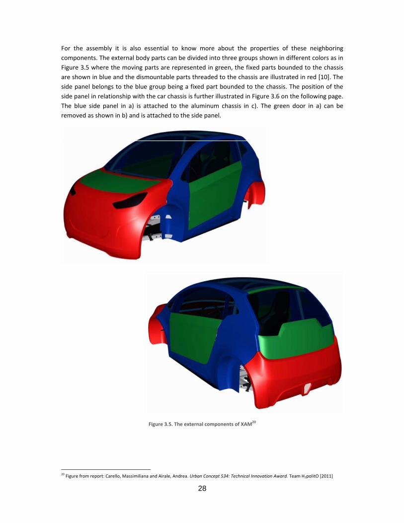
For the assembly it is also essential to know more about the properties of these neighboring components. The external body parts can be divided into three groups shown in different colors as in Figure 3.5 where the moving parts are represented in green, the fixed parts bounded to the chassis are shown in blue and the dismountable parts threaded to the chassis are illustrated in red [10]. The side panel belongs to the blue group being a fixed part bounded to the chassis. The position of the side panel in relationship with the car chassis is further illustrated in Figure 3.6 on the following page. The blue side panel in a) is attached to the aluminum chassis in c). The green door in a) can be removed as shown in b) and is attached to the side panel.
Figure 3.5. The external components of XAM20
20 Figure from report: Carello, Massimiliana and Airale, Andrea. Urban Concept 534: Technical Innovation Award. Team H2politO [2011]

29
Figure 3.6. The placement of the side panel with respect to the car chassis21
21 Figure from report: Carello, Massimiliana and Airale, Andrea. Urban Concept 534: Technical Innovation Award. Team H2politO [2011]
a)
b)
c)

SummarMost of nregarding Figure 3.7result of inbe divided
RecommFinding acomplexitAnother swith corre
A study whow the aof a detaifor future
3.4. When desto be takeTeam H2pmore aboabout the
The wheeinside as which cansurface sheven entewheel is n
22 Producer: LAutodesk Alia
ry and Obseneighboring pthe producti
7, making thencreasing thed in parts eve
Figu
mendations n alternativety of the masolution is to esponding ho
within the areassembly of thled plan showimprovemen
Aero Dysigning a sideen into considpolitO interestout how the d questions as
l of XAM is alillustrated in n lead to an ihape. In a perering the whenot necessary
Lisa Nääs. Student as Design: version
ervations parts and theion process. Te production e cost of moldry time a new
ure 3.7. The shap
e way of fasnufacturing. add fasteningles in the side
ea of producthe side panelwing the assents.
ynamics e panel of a caderation. An ited in aero ddesign of thesked during th
ligned to the Figure 3.8. Tncrease of kirfect case, theel arch. In t due to the lo
– Design and Prod2012 and Edraw M
e assembly oThe upper pacomplex by fd manufacturw piece is to b
pe of the side pa
stening the An example g plugs that ce panel for as
tion complex in relation toembly of the e
ar, the aero dnterview withdynamics [11] side panel ohe interview,
external bouThe purpose inetic energye air would fthe case of Xow speed of t
duct Realization. KMax: version Profe
30
f these to thart of the sideforcing the mring and the tbe parted from
anel makes the
roof panel tis to attach
could be diressembly.
xity is recommo the roof panentire car wo
dynamical resh the master ] took place tof XAM is relasee the third
undary of the is to avoid oy [12]. This is flow past the XAM, a compthe car.
KTH Royal Instituteessional 5.2, 2010
he side panele panel howe
mold to be matime of produm the mold a
manufacturing
to the side the roof pactly included
mended for rnel could be iould also be o
strictions comstudent Roozthe 1st of Novated to aero d interview in
fender and sr decrease thpossible by awheel and s
plete eliminat
e of Technology [2
l did not cauever is curvedade of two pauction since tafter curing.
complex22
panel couldnel by the hin the struct
receiving a dimproved. A dof interest as
mbined with azbeh Hashemvember in ordynamics. FoAppendix 1 –
side panel, or he vortex aroavoiding suddide panel smtion of air flo
2011], Software us
se any troubd for assembarts. This hashe mold has
decrease thhelp of screwure of the ro
etailed plan documentatioa ground wo
aesthetics havmi, a member der to find oor more deta– Interviews.
maybe slightound the wheden changes oothly withoow around th
sed to create Figur
ble ly, s a to
he ws. oof
of on ork
ve of ut ils
tly eel in ut he
re:

In additiospoon shaarch instebehind anthe air vol
23 Producer: LVehicle Aero 24 Producer: LAutodesk Alia
n the fender ape is causedead of lettingnd around thlume in the w
Figure 3.
Lisa Nääs. Student Dynamics, ChapteLisa Nääs. Student as Design: version
Figure 3.8.
is designed id when the rg it flow paste wheels in awheel compar
9. The lokary is
– Design and Prod
er 2, lecture slide b– Design and Prod2012 and Edraw M
The arrows sho
n order to avoundings havt the side of accordance wrtment in diso
added to reduc
duct Realization. Kby Professor Paoloduct Realization. KMax: version Profe
31
ow how we want
void “spoon” ve too big ofthe wheel. A
with Figure 3.ordered moti
ce the air volum
KTH Royal Instituteo Massai, PolytechKTH Royal Instituteessional 5.2, 2010
t the air to flow
shape that cf a radius leaA smooth lok.9. The purpoon [12].
e in the wheel c
e of Technology [2nic University of Te of Technology [2
w23
can create meding the air kary (wheel ose is once a
compartment24
2011]. Hand sketchTurin. 2011]. Software us
ess and drag.into the whearch) is placegain to redu
h inspired by Land
sed to create Figur
A eel ed ce
re:

32
Summary and Observations The most important part of the side panel in terms of aero dynamics is the wheel arch. Other than that the side panel does not have any major influence of the total aero dynamics of the vehicle as long as its shape is continuous and smooth avoiding drastic changes. Being part of a city car with a low maximum speed, the current design of the side panel has not experienced any major difficulties in terms of aero dynamics.
Recommendations There is always room for improvements regardless of the essentialness of these. One advice of how to improve the aero dynamics further could be to add a brake cooling duct to the frontal wheel arch passing through it to the rear wheel arch. This would be done to decrease the air volume around the wheels further in order to not loose kinetic energy when the speed of the car increases. This is not an essentially important change because of the current speed limits of XAM, but might be necessary for future development of the car if it will be able to drive faster in the future. Another possibility with similar results would be to add a sill below the side panel. For an exact shape and design of a possible sill or brake cooling duct, a deeper study within the field would have to be made.
3.5. Overall Summary and Conclusion To have an understanding of the different factors behind the design of the side panel is essential when looking for improvements. The recommendations are given for the possibility of continuing the development of the side panel for future production. The problems were spotted so that solutions could be found. It is important to know that the recommendations are given as a brief foundation for creating ideas for future detail studies.
The sharp corners have caused problems during the production of the side panel that can easily be decreased by increasing the radius of the sharp corners. It is shown that the manufacturing methodology and the assembly of the side panel to the neighboring components are closely related. By studying the assembly for improvement, the manufacturing costs and time can decrease. The goal is to make the mold for small scale production in one piece instead of two.
When it comes to aero dynamics, many solutions exist. The question is if these improvements are necessary in the case of an urban city car with a low maximum speed. Further studies within these fields are recommended for more details within all of these areas.

Chap
A bench mcommon analysis. Sin short. Tsystems. Sa side panwill be sta
4.1. Ten of the
• Co
• Au
• Ha
• Fi
• Re
• Bu
• Pu
• Sh
• Va
• Va
4.2. The matereinforcedof XAM isproductiosame comthough, a the most of a side p
The side order:
FlaxPreg iphoto shothird phot
pter 4.
marking reprproduction sSome specificThe purpose Some of the snel even thouated in Chapte
Backgroe most comm
ompression m
utoclave mold
and lay‐up/ s
lament windi
esin transfer
ulk molding c
ultrusion
heet molding
acuum and p
acuum assiste
Flax Fiberial used ford with flax fibs made of thisn (small scal
mponent, it isbench markisuitable mecpanel.
panel of the
s made of 50ows the naturto illustrates t
BenPro
resenting a gsystems for cations of theof the benchsystems will lugh introduceer 5.
ound only used pro
molding
ding
pray lay‐up
ing
molding (RTM
compound (BM
compound (S
ressure bag m
ed resin trans
er r the producber. The purpos material. Inle productions favorable tong about diffhanical and p
prototype o
• • • •
0% thermosetral flax fiber cthe cloth whe
nch Markiduction Sgeneral overvcomposite me specific comh marking waater on be shed here. The m
oduction met
M)
MC molding)/
SMC molding
molding
sfer molding
ction of the ose of choosin order to don) and possibo keep the saferent materiphysical chara
of XAM is com
1st lay
2nd la
3rd la
4th la
tting epoxy recloth, the secen gel coat ha
33
ing – an InSystems view of the mmanufacturingmposite mates to get a gehown to not bmotivation of
thods [13] for
/ Dough mold
g)
(VARTM)
side panel ising flax fiber a comparisoble future meame materialals has to be acteristics wi
mposed of 4
yer: FlaxPreg
ayer: FlaxPreg
yer: FlaxPreg
yer: FlaxPreg
esin and 50%cond one the as been appli
ntroducti
methodologieg was carrieerial used (flaneral idea abbe suitable fof why to keep
r composite p
ding compoun
s FlaxPreg –was that the on between tedium to larl. For futuremade in ordeth respect to
layers of Fla
UD180, Unid
g BL200, 0/90
g BL200, 0/90
UD180, Unid
% flax fiber facloth provideed resulting i
on to Com
es of some od out for cox fiber) are about the curreor the purposp or eliminate
production inc
nd (DMC mol
thermosettinside panel ofhe already mrge scale pro developmener to choose ao the needed
axPreg put in
directional, 18
0 Balanced, 20
Balanced, 20
directional, 18
brics. In Figured with epoxn a black colo
mposite
f today’s moomparison analso introduceent productiose of producine each metho
clude:
ding)
ng epoxy resf the prototypmade prototypduction of thnt of this studa material wicharacteristi
n the followin
80 g/m2
00 g/m2
00 g/m2
80 g/m2
re 4.1, the firy resin and thor.
ost nd ed on ng od
sin pe pe he dy th ics
ng
rst he

34
Figure 4.1. Flax fiber cloth with epoxy resin and then gel coat providing a black color25
The mechanical properties of the FlaxPreg are:
• Density ρ: 1.45 kg/m3
• Tensile strength σ: 330 MPa (traction)
• Young’s modulus E: 35 GPa (traction)
For more specific technical data about FlaxPreg, see Appendix 2 – Data Sheet of FlaxPreg [14].
4.3. Composite Production The composite production methods are presented in short throughout this chapter by briefly explaining the different steps of each method.
Compression molding For large scale production, compression molding is economically effective. One steel die is capable of producing up to 200 000 components so even if expensive in itself, a production volume exceeding 10 000 parts would pay for the die. The method is applied to simple shape production and commonly used for thermosetting short fiber filled composites (25 mm). In compression molding, the following simplified methodology is used [15] and Figure 4.2 illustrates the process.
Step 1: Mold Preparation The surface of the mold is finished and heated.
Step 2: Polymer Placed in Mold Granules or a tablet of polymer (most commonly thermoset resin and hardener) is placed in the heated mold.
Step 3: Closure of Mold The mold is closed with a pressure big enough to make the polymer fill the mold cavity.
Step 4: Polarization The polymer is left inside of the closed mold for curing.
Step 5: Extraction After opening the mold, the cured component is removed for surface finishing.
Step 6: Surface Finishing and Painting The surface of the component is finished and then painted.
25 Photographer: Lisa Nääs Student – Design and Product Realization. KTH Royal Institute of Technology [2011]

Bulk MoBMC/ DMmanufactumethods fcast iron fibers (25 [13].
Step 1: MThe surfac
Step 2: PoA preformplaced in t
Step 3: ClThe mold the shape
Step 4: PoSteam, elinitiate th
Step 5: ExAfter open
Step 6: SuThe surfac
26 Hand sketchFigure: Adobe
lding CompMC molding uring of compfor large scalor steel. Usumm) random
Mold Preparace of the mol
olymer Placem of polymerthe heated m
losure of Mois closed wit of the mold
olarization ectricity or he curing of th
xtraction ning the mold
urface Finishce of the com
h by: Lisa Nääs. Ste Photoshop Elem
pound (BMCis a kind of ponents of smle productionually thermopmly orientated
ation d is finished a
ed in Mold r (most commmold.
old th a pressure cavity.
hot oil heats he resin.
d, the cured c
hing and Painmponent is fin
udent – Design anents: Version 6.0,
Figure 4.2. Com
C), Dough Mcompressio
mall to mediun of compositplastic resinsd [15]. BMC/
and heated.
monly therm
ranging betw
the mold to
component is
nting ished and the
nd Product Realiza2000 and Edraw M
35
mpression mold
Molding Comn molding aum size. It is ote products. s are used wDMC molding
oset resin, re
ween 0.5 and
o a temperatu
s removed for
en painted.
tion. KTH Royal InMax: version Profe
ding26
mpound (Dand a producone of the moThe mold is ith a reinforcg is carried ou
einforcement
15 MPa and
ure of appro
r surface finis
nstitute of Technolessional 5.2, 2010
DMC) ction systemost cost effectusually madecement of 25ut following t
t, catalyst an
d the polymer
oximately 150
shing.
logy [2011]. Softw
m used for thtive productioe of aluminum5‐70% of shohe steps belo
nd hardener)
r fills and tak
0°C in order
ware used to edit
he on m, ort ow
is
es
to

36
Sheet Molding Compound (SMC Molding) SMC molding is also a form of compression molding but where the production rates are smaller and the cost per unit is less than that of the compression molding due to the use of sheet molding compounds. With today’s technology, the production rate can go down to no more than 60 seconds per unit produced [15]. Only components of sheet shape can be manufactured with this methodology. Epoxy resin reinforced with long fibers (25‐75 mm) is common. SMC molding follows the simplified methodology explained in steps below [13].
Step 1: Mold Preparation The surface of the mold is finished and heated.
Step 2: Mold Placed in Press The mold is placed into a heated press.
Step 3: Polymer Placed in Mold A sheet molding compound (most commonly a premix of thermoset resin, reinforcement, catalyst and additives) is placed in the mold.
Step 4: Closure of Mold and Polarization The mold is closed and the panel is formed and cured due to an applied pressure of 3‐7 Mpa and heat.
Step 5: Extraction After opening the mold, the cured component is removed for surface finishing.
Step 6: Surface Finishing and Painting The surface of the component is finished and then painted.
Resin transfer molding (RTM) Resin transfer molding is an effective method for producing complex shapes. The system most commonly uses a thermosetting resin reinforced with 25‐30% of filament cloth. As it is a closed mold system, the contact between employees and damaging chemicals is less than in the case of open mold systems. The following steps and Figure 4.3 illustrate how resin transfer molding is carried out [13].
Step 1: Mold Preparation The surface of the mold is finished and the mold is closed around a reinforcement + inserts or fittings.
Step 2: Injection A low viscosity resin (thermosetting) is injected with a pressure of approximately 2 MPa into the closed mold through mixing heads and injection points. In the mixing heads, the resin is combined with a hardener. Due to the low pressure, the tools can be used for a long time and at a low cost.
Step 3: Polarization The polymer is left inside of the closed mold for curing in room temperature.

Step 4: ExThe mold
Step 5: SuThe surfac
AutoclavAutoclave
Step 1: MThe surfafacilitating
Step 2: LaA matrix blay‐up.
Step 3: PrA breathethe excess
Step 4: PoThe compto extract
Step 5: ExThe piece
27 Hand sketchFigure: Adobe
xtraction is opened an
urface Finishce of the com
ve molding e molding is li
Mold Preparace of the mg the extracti
amination brushing of re
reparation fer (film of pors resin. The la
olarization ponent is placthe air to cre
xtraction is taken out f
h by: Lisa Nääs. Ste Photoshop Elem
d the cured c
hing and Painmponent is fin
mited to simp
ation mold is finishon of the com
esin and reinf
for Autoclaveous plastic) aaminate (with
ced in an autoeate a vacuum
from the vacu
udent – Design anents: Version 6.0,
component re
nting ished and the
Figure 4.3. Res
ple shapes an
ed and “relemponent from
forcement is
e Treatmentand an absorbh breather an
oclave wherem around the
uum bag and
nd Product Realiza2000 and Edraw M
37
emoved.
en painted.
in transfer mold
nd follows the
ease paint” im the mold.
manually put
t bent are put od absorbent)
e air pumps a laminate und
separated fr
tion. KTH Royal InMax: version Profe
ding27
e subsequent
is sprayed o
t onto the mo
on top of the is then cover
are connectedder a pressur
om the mold
nstitute of Technolessional 5.2, 2010
steps [13].
nto the mol
old through s
laminate in ored in a plast
d to the plastre of 0.55 MP
.
logy [2011]. Softw
d in order f
spray‐ or han
order to absoic bag.
tic bag in orda.
ware used to edit
for
d‐
rb
er

Step 6: SuThe surfac
Hand layHand/ spproductiothat the rillustrated
Step 1: MThe surfac
Step 2: ReThe open
Step 3: ReWhen the
Step 4: BrA new layspray gun
Step 5: PoThe comp
Step 6: ExThe comp
Step 7: SuThe surfac
28 Hand sketchFigure: Adobe
urface Finishce of the com
yup/ Sprayray lay‐up isn of large sizrest of the tod in Figure 4.4
Mold Preparace of the mol
esin Coat mold is cove
einforcemene resin is cure
rush or Spraer of resin is . Steps 2‐4 ar
olarization ponent is left
xtraction ponent is sepa
urface Finishce of the com
h by: Lisa Nääs. Ste Photoshop Elem
hing and Painmponent is fin
y layup s a manual pze parts. Theooling can be4 [13].
ation d is finished.
red in a layer
nt d, a layer of r
ay Gun placed to covre repeated u
in the open m
arated from t
hing and Painmponent is fin
udent – Design anents: Version 6.0,
nting ished and the
production m mold is usue achieved at
of resin that
reinforcemen
ver all of the ntil the want
mold for curin
he mold.
nting ished and the
Figure 4.4
nd Product Realiza2000 and Edraw M
38
en painted.
method mainally made of t a very low
is left to cure
nt is manually
fibers of the ted section th
ng.
en painted.
4. Hand lay‐up28
tion. KTH Royal InMax: version Profe
nly used for wood, plastecost. It is fu
e.
placed on to
reinforcemenhickness of th
8
nstitute of Technolessional 5.2, 2010
prototyping er or metal aurther explain
op of the coat
nt by the use e component
logy [2011]. Softw
or small scaand other thaned below an
t of resin.
of a brush ort is reached.
ware used to edit
ale an nd
r a

FilamenFilament wof steel or
Step 1: WReinforcemandrel u
Step 2: CuThe comp
Step 3: ExThe comp
Step 4: SuThe surfac
PultrusiThe shapeextraction
Step 1: StSteel form
Step 2: PuFibers or shape.
Step 3: CuThe last d
Step 4: CuThe mater
29 Hand sketchFigure: Adobe
t winding winding is a pr plastics. The
Winding ment in the funtil the want
uring ponent is left o
xtraction ponent is rem
urface Finishce of the com
ion e of pultrusion system is re
teel Formingming dies are
ulling fabrics + res
uring ie is heated in
utting rial is cut into
h by: Lisa Nääs. Ste Photoshop Elem
production mee process is he
form of rovinted section th
on the mandr
oved from th
hing and Painmponent is fin
on depends quired due to
g Dies put in a desir
sin are pulled
n order to init
o desired leng
udent – Design anents: Version 6.0,
ethod producere introduce
g or tape is imhickness of th
rel until cured
he mandrel.
nting ished and the
Figure 4.5. F
on the crosso excess mate
red order.
d through the
tiate curing o
gths.
nd Product Realiza2000 and Edraw M
39
cing symmetred in short an
mpregnated whe component
d.
en painted.
Filament windin
s section of terials and che
e steel formi
of the materia
tion. KTH Royal InMax: version Profe
rical shapes. Tnd illustrated
with resin ant is achieved.
g29
the die whichemicals [13], s
ng dies in or
al.
nstitute of Technolessional 5.2, 2010
The mandrel in Figure 4.5
d winded aro.
h is made ofsee Figure 4.6
rder to achie
logy [2011]. Softw
is mainly mad[13].
ound a rotatin
f steel. A goo6.
ve the desire
ware used to edit
de
ng
od
ed

Step 5: SuThe surfac
VacuumIn vacuumpreferably
Step 1: MThe surfafacilitating
Step 2: LaA matrix blay‐up.
Step 3: VaA breathethe excess
Step 4: PoAir pumpslaminate u
Step 5: ExThe piece
Step 6: SuThe surfac
30 Hand sketchFigure: Adobe
urface Finishce of the com
and pressum and pressuy simple [13].
Mold Preparace of the mg the extracti
amination brushing of r
Vacuum Bag er (film of pors resin. The la
olarization s are connecunder pressu
xtraction is taken out f
urface Finishce of the com
h by: Lisa Nääs. Ste Photoshop Elem
hing and Painmponent is fin
ure bag moure bag mold
ation mold is finishon of the com
esin and rein
ous plastic) aaminate (with
cted to the bre and cure t
from the vacu
hing and Painmponent is fin
udent – Design anents: Version 6.0,
nting ished and the
Figure 4.
olding ing a mold m
ed and “relemponent from
nforcement is
and an absorbh breather an
bag in order he componen
uum bag and
nting ished and the
nd Product Realiza2000 and Edraw M
40
en painted.
.6. Pultrusion30
made of epox
ease paint” im the mold.
s manually pu
bent are put od absorbent)
to extract thnt.
separated fr
en painted.
tion. KTH Royal InMax: version Profe
xy or metal i
is sprayed o
ut onto the m
on top of the is then cover
he air and cr
om the mold
nstitute of Technolessional 5.2, 2010
is used and t
nto the mol
mold through
laminate in ored in a vacuu
eate a vacuu
.
logy [2011]. Softw
the shapes a
d in order f
spray or han
order to absoum bag.
um around th
ware used to edit
re
for
nd
rb
he

41
Vacuum assisted resin transfer molding (VARTM) Complex shapes are here possible and the process is economic for small scale production volumes. The method of VARTM is introduced in steps below [15].
Step 1: Mold Preparation The surface of the mold is finished.
Step 2: Reinforcement Placed in Mold The reinforcement (dry woven fabric) is put in the mold.
Step 3: Peel Ply Peel ply covers the reinforcement.
Step 4: Vacuum Bag The mold plus the reinforcement and the peel ply is covered with a vacuum bag.
Step 5: Release of Excess Resin Excess resin is extracted when vacuum is created around the component (by the help of a breather and an absorbent).
Step 6: Curing The component is cured.
Step 7: Extraction The vacuum bag is opened and the component separated from the mold.
Step 8: Surface Finishing and Painting The surface of the component is finished and painted.
4.4. Recommendations and Conclusion These methods are all found in the software CES EduPack 2011 [13] which presents basic descriptions and data. It is important to remember that current technology of the methodologies are constantly improving and might develop into new methods even more suitable for the application of the side panel in the near future. This is why this chapter might be in need of modifications before the actual medium to large scale production of the side panel is transferred from theory into practice.

42

43
Chapter 5. Composite Production with respect to the Side Panel
The different production systems for composite production are evaluated with respect to the side panel of XAM and its future medium to large scale production in terms of dimensional limits, economical characteristics and production rates. All data are approximate values achieved by the help of the software CES EduPack 2011 [13] and the graphs are made thereafter. For numerical values, see Appendix 4 – Physical Attributes and Appendix 5 – Economical attributes. The costs were converted from Swedish crowns to Euros by the help of Forex Currency Converter [16].
5.1. Background The main idea and purpose behind these comparisons was to get a deeper insight into whether the different factors could be applied to the production of the side panel or not and thereafter, on the basis of the results, eliminate or keep the production methods for further analysis.
5.2. Dimensional Limits A general analysis of some of the dimensional limits ‐ including the possible mass range, range of section thickness, roughness and shape ‐ of the 10 composite methods was done with respect to the physical characteristics and dimensional limits of the side panel. The purpose was to understand if the dimensional limits of the side panel would be applicable to all of the chosen production systems.
Mass Range The mass of the side panel is approximately 5 kg and can be considered a small or medium sized component. Table 5.1 shows the recommended mass range in kg for a component produced with the 10 composite methods that were introduced in Chapter 4.
Table 5.1. The recommended mass range of a component produced using different methods31
Mass Range [kg]
min max
Compression molding 0.1 20
Autoclave molding 0.8 2000
Hand/spray lay‐up 1 6000
Filament winding 0.01 3000
RTM 0.8 50
BMC/DMC molding 0.03 50Pultrusion 0.1 200SMC molding 0.03 50Vacuum bag molding 0.8 2000VARTM 0.5 600
Having this data as a reference, all of the mentioned production systems would be applicable for the future production of the side panel. For a mass up to 20 kg, any of the production methods can be used. When exceeding 50 kg however, compression molding, RTM, BMC/DMC molding and SMC molding are no longer recommended because of the large compression force required for bigger components. Products with a mass larger than 1000 kg are recommended to be produced with 31 Producer: Lisa Nääs. Student – Design and Product Realization. KTH Royal Institute of Technology, Software used to create table: Microsoft Office Excel: version, 2007

44
autoclave molding, hand/spray lay‐up, filament winding, vacuum bag molding or a combination of these. Components produced with these methods do not necessarily have to be of a high mass, but the mass range is a lot bigger for them than for the other production methods.
Section Thickness The side panel has a section thickness of approximately 2 mm. The recommended section thicknesses in mm for giving a result with good mechanical characteristics for the different composite production methods are illustrated in Table 5.2.
Table 5.2. The recommended range of section thickness of a component produced using different methods32
Range of section thickness [mm]
min max
Compression molding 1.5 25
Autoclave molding 2 30
Hand/spray lay‐up 2 10
Filament winding 2 25
RTM 2 6
BMC/DMC molding 1.5 25
Pultrusion 3 15
SMC molding 1.5 25Vacuum bag molding 2 6VARTM 1 20
For the purpose of keeping the recommended mechanical characteristics of the side panel, all of the above mentioned production systems could be used for its future production. It is noted that the maximum recommended section thickness for composite production is 30 mm (in the case of autoclave molding), while the minimum is 1 mm (VARTM). Having a larger section thickness requires more material than necessary resulting in higher costs of both material supply and production process. For a section thickness below 1 mm, the mechanical properties might become too low. The smallest range of section thickness is that for RTM and vacuum bag molding, while the method of autoclave molding has the possibility of creating products with a greater range of section thickness compared to all of the other mentioned composite production methods.
Surface Roughness The surface quality of the side panel must be of Class‐A in accordance with high quality car production. A Class‐A surface is usually a surface that the customer can see, and can thereby include both the exterior and the interior surfaces of a car.
According to the company Design Engine [18] a Class‐A surface is a surface following the criteria listed below (quoted):
32 Producer: Lisa Nääs. Student – Design and Product Realization. KTH Royal Institute of Technology, Software used to create table: Microsoft Office Excel: version, 2007

45
• The fillets: generally for Class‐A, the requirement is continuous curvature and uniform flow of flow lines from fillet to parent surface with a value of 0.005 mm or better (position 0.001 mm and tangency to about 0.016°).
• The flow of the highlight lines: the lines should form a uniform family of lines, gradually widening or narrowing but in general never pinching in and out.
• The control points should form a very ordered structure: again varying in angle from one row to the next in a gradual manner (this will yield the good highlights required).
• For a Class‐A model the fillet boundary should be edited and moved to form a gentle line and then re‐matched into the base surface.
• Matched ISO‐parameters in U & V direction are also a good representation of Class‐A.
• The draft angle, symmetry, gaps and matching of surfaces should apply to parent or reference surfaces.
There is nothing stated about the values of surface roughness for a Class‐A surface. The lower the possible surface roughness of a production method however, the easier it is to create a result with a surface of high quality. Table 5.3 thereby shows the roughness in µm of a component produced using composite manufacturing methods.
Table 5.3. The range of roughness in µm of the surface of a component produced using different production methods33
Roughness [µm]
min max
Compression molding 0.2 1.6
Autoclave molding 0.5 3.2
Hand/spray lay‐up 0.5 3.2
Filament winding 0.5 1.6
RTM 0.25 1.6
BMC/DMC molding 0.3 1.6
Pultrusion 0.3 1.6
SMC molding 0.3 1.6Vacuum bag molding 0.5 3.2VARTM 1 2.4
All of the mentioned production methods have the possibility of generating a component with a surface of low roughness (≤ 1 µm) and thus also the possibility of creating a surface quality of Class‐A [17]. None of them have to be excluded with respect to the surface roughness of the side panel.
Shape It is essential to know the different groups of shape that a certain production method can create for understanding if it could be relevant to the future production of the side panel. In Figure 5.1, one can see these different groups – prismatic, sheet and 3‐D shapes – in the form of a block diagram inspired by a similar diagram in Materials engineering, science, processing and design [18].
33 Producer: Lisa Nääs. Student – Design and Product Realization. KTH Royal Institute of Technology, Software used to create table: Microsoft Office Excel: version, 2007

The curreproductiohave to beshapes tha
PRODUCT
ION SYSTEM
CommoAutmoHanSprFilawinResmoBMmoPultSMmoVacpremoVacresimo
With the methods eexcluded, procedure 34 Producer: LMax: version 35 Producer: LMicrosoft Off
nt shape of tn methods we found for tat each of the
mpression lding toclave lding nd lay‐up/ ray lay‐up ament nding sin transfer lding (RTM)
MC (DMC) lding trusion C lding cuum and essure bag lding cuum assistedin transfer lding VARTM
restriction oexcept for filanot because
e of a non‐sym Lisa Nääs. StudentProfessional 5.2, 2Lisa Nääs. Student fice Excel: version,
Figure 5
the side panewith the oppohe planning oe production
Table 5.4.
Circular prismatic
X
X
X
X
X
d
M
f dished sheeament windine of the commmetric shap – Design and Prod2010 – Design and Prod 2007
5.1. Different sha
el belongs to ortunity of fulof the future system can m
. Possible shape
c Non‐
circular prismatic
X
X
X
X
X
et or solid 3ng which is thmplexity of tpe. Of the rem
duct Realization. K
duct Realization. K
46
apes divided up
the group offilling at leasproduction omanufacture.
es for each prod
S
c
Flat shee
X
X
X
X
X X
X
X
‐D, the side hereby excluthe shape bumaining meth
KTH Royal Institute
KTH Royal Institute
p into groups34
f dished sheet one of thosof the side pa
uction system35
SHAPEet Dished
sheet
X
X
X
X
X X
X
X
panel can beded from theut because ohods, compre
e of Technology, S
e of Technology, S
et or solid 3‐Dse two characanel. Table 5.4
5
Solid 3D
X
X
X
X
e produced ue list. Pultrusiof the compession moldin
Software used to c
oftware used to c
D which is whcterized grou4 identifies th
D Hollow3D
X
X
X
X
X
X
using all of thion can also bplicated cuttinng and RTM a
create Figure: Edra
reate table:
hy ps he
w
he be ng re
aw

47
the two that have the possibility of producing a component with a shape of both dished sheet and solid 3‐D while BMC/DMC molding is more fit for solid 3‐D shapes than for dished sheets. Autoclave molding, hand/spray lay‐up, SMC molding, vacuum and pressure bag molding as well as vacuum assisted RTM are all methods in which a dished sheet is to prefer in front of a solid 3‐D shape.
Summary and Observations The recommended mass range, section thickness and surface roughness of the composite production methods are all within the boundaries of the dimensional limits of the side panel. Up to a mass of 20 kg, the side panel can still be produced regardless of the production method. The section thickness is not recommended to be less than 2 mm due to the dimensional limits of the equipment, but also because of the difficulty of parting the cured component from the mold as explained in Chapter 3. The surface roughness needed for achieving a Class‐A surface quality can be attained using all of the declared composite methods. The limitations in terms of the shape of the side panel exclude filament winding and pultrusion from the list of possible manufacturing methods for future production.
Recommendations The recommendation given regarding the dimensional limits of the side panel is to not consider the two excluded methods for future production of the side panel.
5.3. Economical Characteristics A general analysis of some of the economical characteristics ‐ including the labor intensity, economic batch size, capital cost and tool life ‐ of the 10 composite methods was done with respect to the side panel. The purpose was to get an overview of the most fundamental economic factors for understanding which methods might be suitable for a future production of the side panel.
Table 5.5 shows the relative ranking of what is considered to be low, medium, high and very high costs of production systems. The costs taken in account are approximate and consist of tooling cost, equipment cost and labor intensity. All of the definitions of the economic terms used in this chapter can be found in Appendix 5 – Economical attributes [13].
Table 5.5. The relative ranking corresponding to the costs36
Relative ranking
Tooling cost[€]
Equipment cost,[€]
Labor intensity [hours/unit]
Low < 700 < 7∙103 < 0.1 Medium 700 – 7∙103 7∙103 – 7∙104 0.1 – 30 High 7∙103 – 7∙104 7∙104 – 7∙105 30 – 300 Very high > 7∙104 > 7∙105 > 300
Labor Intensity The labor intensity identifies if a production system requires a lot of employees which also indicates how much manual work versus automatic work is needed. Usually when the labor intensity is high, the process is predominantly manual while low labor intensity indicates that a greater portion of the process is automatic. Table 5.6 shows the labor intensity for different composite production systems. The ranking is made in accordance with Table 5.5.
36 Producer: Lisa Nääs. Student – Design and Product Realization. KTH Royal Institute of Technology, Software used to create table: Microsoft Office Excel: version, 2007

48
Table 5.6. The labor intensity of different composite production systems37
Labor intensity
Compression molding LowAutoclave molding High Hand/spray lay‐up High RTM High BMC/DMC molding MediumSMC molding Medium Vacuum bag molding Medium VARTM Medium
The only method with low labor intensity is compression molding, while all of the other methods have a medium to high labor intensity. Autoclave molding, hand/spray lay‐up and resin transfer molding are the methods requiring the highest labor intensity.
Economic Batch Size The economic batch size gives an idea about the approximate production volume that would have to be manufactured to make a process economically imperishable. A summary of the economic batch size is listed below in terms of different scales of production for profitability of the different composite methods and the economic batch sizes in units are shown in Table 5.7.
Table 5.7. The economic batch size in units of different composite production systems38
Economic batch size [units]
Compression molding 500‐2∙106 Autoclave molding 1‐500 Hand/spray lay‐up 1‐500 RTM 1∙103‐1∙106
BMC/DMC molding 5∙103‐1∙106 SMC molding 5∙103‐1∙106 Vacuum bag molding 1‐1∙103 VARTM 10‐500
Small scale production (≤ 1 000 pieces/year) • Compression molding
• Autoclave molding
• Hand lay‐up/ spray lay‐up
• RTM
• Vacuum and pressure bag molding
• VARTM
37 Producer: Lisa Nääs. Student – Design and Product Realization. KTH Royal Institute of Technology, Software used to create table: Microsoft Office Excel: version, 2007 38 Producer: Lisa Nääs. Student – Design and Product Realization. KTH Royal Institute of Technology, Software used to create table: Microsoft Office Excel: version, 2007

49
Medium scale production (10 000 pieces/year) • Compression molding
• Resin transfer molding (RTM)
• BMC/DMC molding
• SMC molding
Large scale production (100 000 pieces/year) • Compression molding
• RTM
• BMC/DMC molding
• SMC molding
Compression molding and RTM are economically suitable for all of the different production volumes while BMC/DMC molding and SMC molding are fit for medium to large scale production. Other than compression molding and RTM; autoclave molding, hand/spray lay‐up, vacuum and pressure bag molding and vacuum assisted resin transfer molding are able to produce an economic batch size within the limits of small scale production only. The remaining methods of interest for a future medium to large scale composite production are thereby compression molding, RTM, BMC/DMC molding and SMC molding.
Capital Cost Tool and equipment cost make up the capital cost of a production system. Table 5.8 shows the capital cost in 1 000 € for the different systems.
Table 5.8. The capital cost of the different production systems39
Capital cost [1 000 €] min maxCompression molding
11.8 70.6 High
Autoclave molding 47 588 MediumHand/spray lay‐up 0.058 0.588 LowRTM 5.88 35.3 Medium/highBMC/DMC molding
0.353 353 Medium
SMC molding 35.3 353 MediumVacuum bag molding
23.6 588 Low/medium
VARTM 0.588 11.8 Low/medium
The methods with highest capital cost are autoclave molding, filament winding and vacuum and pressure bag molding indicating that an autoclave has a high cost. The methods with low capital cost are hand/spray lay‐up, RTM and VARTM which all have an economic batch size within the limits of a small scale production while the labor intensity is medium to high causing higher employment costs.
39 Producer: Lisa Nääs. Student – Design and Product Realization. KTH Royal Institute of Technology, Software used to create table: Microsoft Office Excel: version, 2007

50
Tool Life Table 5.9 shows the tool life in units produced before the tool is torn out and has to be replaced or repaired.
Table 5.9. The tool life in units for the different production systems40
Tool life [units] min max
Compression molding 2 000 200 000Autoclave molding 99 100Hand/spray lay‐up 200 1 000Filament winding 1 000 10 000RTM 500 5 000BMC/DMC molding 100 000 200 000Vacuum bag molding 1 040 17 800VARTM 100 1 000
The tools used in compression molding and BMC/DMC molding have a life of up to 200 000 units/tool. These two methods can thereby be used for a mass scale production being able to produce more than 100 000 units/tool. On the other hand, if using methods with low capital cost the economic benefits might still be able to cover large scale production since a change of tool does not result in a big investment for the production company. The tool life of filament winding and SMC molding falls in the category of medium scale production while autoclave molding, hand/spray lay‐up, vacuum bag molding and VARTM all go within the limits of medium scale production. The RTM method have tools with a tool life of 5 000 units/tool leaving it somewhere in between a small scale and a medium scale production before changing tool, but since the capital cost of the tools is low, it can easily be replaced and a higher scale production is possible.
Summary and Observations It is essential to know the combination of labor intensity, economic batch size, capital cost and tool life in order to get an understanding of where to place the different production volumes for future production. Labor intensity, capital cost, economic batch size and tool life are all factors that are related to each other. The economic batch size depends on the combination of the level of labor intensity, capital cost and tool life. The economically most profitable combination for all production volumes would be a low labor intensity, low capital cost and long tool life resulting in a wide range of economic batch size. The worst case would be having a high labor intensity, high capital cost and short tool life making it almost impossible to reach an economic batch size.
When the economic batch size lies within a small scale production volume, it can be seen that the labor intensity in five out of six cases (autoclave molding, hand/spray lay‐up, RTM, VARTM and vacuum and pressure bag molding) is medium to high while the capital cost for four of these methods are low to medium, the exception being RTM with a medium to high capital cost. The last method within the group of small scale production based on the economic batch size is compression molding which goes against the other methods with a high capital cost and low labor intensity. Another difference of compression molding in comparison with four of the other small scale production methods based on economic batch size is that it is also considered to lie within its
40 Producer: Lisa Nääs. Student – Design and Product Realization. KTH Royal Institute of Technology, Software used to create table: Microsoft Office Excel: version, 2007
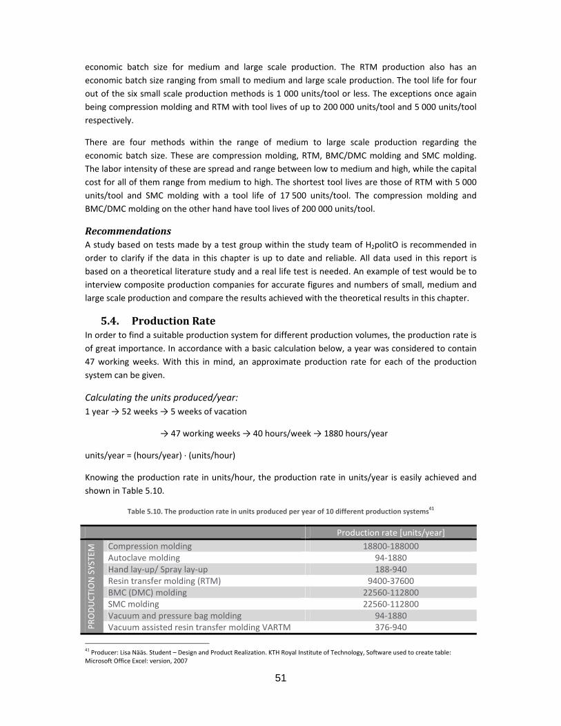
51
economic batch size for medium and large scale production. The RTM production also has an economic batch size ranging from small to medium and large scale production. The tool life for four out of the six small scale production methods is 1 000 units/tool or less. The exceptions once again being compression molding and RTM with tool lives of up to 200 000 units/tool and 5 000 units/tool respectively.
There are four methods within the range of medium to large scale production regarding the economic batch size. These are compression molding, RTM, BMC/DMC molding and SMC molding. The labor intensity of these are spread and range between low to medium and high, while the capital cost for all of them range from medium to high. The shortest tool lives are those of RTM with 5 000 units/tool and SMC molding with a tool life of 17 500 units/tool. The compression molding and BMC/DMC molding on the other hand have tool lives of 200 000 units/tool.
Recommendations A study based on tests made by a test group within the study team of H2politO is recommended in order to clarify if the data in this chapter is up to date and reliable. All data used in this report is based on a theoretical literature study and a real life test is needed. An example of test would be to interview composite production companies for accurate figures and numbers of small, medium and large scale production and compare the results achieved with the theoretical results in this chapter.
5.4. Production Rate In order to find a suitable production system for different production volumes, the production rate is of great importance. In accordance with a basic calculation below, a year was considered to contain 47 working weeks. With this in mind, an approximate production rate for each of the production system can be given.
Calculating the units produced/year: 1 year → 52 weeks → 5 weeks of vacation
→ 47 working weeks → 40 hours/week → 1880 hours/year
units/year = (hours/year) ∙ (units/hour)
Knowing the production rate in units/hour, the production rate in units/year is easily achieved and shown in Table 5.10.
Table 5.10. The production rate in units produced per year of 10 different production systems41
Production rate [units/year]
PRODUCT
ION SYSTEM
Compression molding 18800‐188000
Autoclave molding 94‐1880 Hand lay‐up/ Spray lay‐up 188‐940 Resin transfer molding (RTM) 9400‐37600 BMC (DMC) molding 22560‐112800 SMC molding 22560‐112800
Vacuum and pressure bag molding 94‐1880
Vacuum assisted resin transfer molding VARTM 376‐940
41 Producer: Lisa Nääs. Student – Design and Product Realization. KTH Royal Institute of Technology, Software used to create table: Microsoft Office Excel: version, 2007

52
The production volumes are divided into small, medium and large scale production and by knowing the approximate possible range of production rate for the different methods it was possible to divide them up into the three groups of production volume/year.
Small scale production (≤ 1 000 pieces/year) • Autoclave molding
• Hand/spray lay‐up
• Vacuum and pressure bag molding
• VARTM
Medium scale production (10 000 pieces/year) • RTM
• BMC/DMC molding
• SMC molding
Large scale production (100 000 pieces/year) • Compression molding
• BMC/DMC molding
• SMC molding
Recommendations Like in the case of the economical characteristics of composite production systems with respect to the future production of the side panel, the data used for the analysis of the production rate would have to be double checked through practical tests or interviews. This is necessary for getting a more reliable and complete analysis regarding the matter of optimizing the future production of the side panel.
5.5. Overall Summary and Conclusion A combination of the observations made for the dimensional limits, economical characteristics and production rate makes it possible to eliminate certain production methods while keeping others. The ones that are left for small scale production are autoclave molding, hand/spray lay‐up, vacuum and pressure bag molding and vacuum assisted resin transfer molding. BMC/DMC and SMC molding can be used for both medium and large scale production, while RTM is recommended for only medium scale production and compression molding for large scale production. In total there are four possible methods for a future medium to large scale production. Table 5.11 gives an overview of all the different aspects discussed throughout this chapter.

53
Table 5.11. Overview of the different aspects to consider when choosing a composite production system for the manufacturing of the side panel42
42 Producer: Lisa Nääs. Student – Design and Product Realization. KTH Royal Institute of Technology, Software used to create table: Microsoft Office Excel: version, 2007

54
Chapter 6. Metal Production with Respect to the Composite Production of the Side Panel
The future production of the side panel of XAM is meant to be produced in composite materials, but in order to get a good result it is important to know more about today’s most common production method for body parts. The most commonly used metal (specifically aluminum) production method for car body parts is forging. The dimensional limits, economical characteristics and production rates of metal production are here being generally analyzed with respect to the production of the side panel. The results are compared to the composite production results from Chapter 5 listing advantages and disadvantages of both in order to get an understanding of how composite production differs from metal production.
6.1. Background The main idea behind this analysis was to get a deeper insight into the differences between composite and metal production. The information received in Chapter 5 is used and compared to additional information about forging methods for aluminum production. A summary of the strengths and downfalls of the two methods are given at the end of each section.
6.2. An Introduction to Aluminum Production The main focus of this project is laid on composite production, but it is also of interest to know some features regarding metal production. The reason is to be able to complete a comparison between composite production and metal production on the basis of the reasonability of a future medium to large scale production of the side panel using composites rather than metal.
Background Team H2politO works to decrease the damages on the environment caused by humanity and therefore they strive to develop a green city car. To have a light weight car helps to decrease both the fuel emission as well as other damaging chemical emissions during the entire life cycle of a car. If the result shows that a composite production of the side panel would not be suitable for one reason or another, the whish is to still keep the weight of the car as low as possible. For the case of metal production, a good option would therefore be aluminum with a lower weight in comparison to steel.
Aluminum AL2024 For comparison of composite production to metal production, the alloy Al 2024 was chosen as a result of a recommendation given by Professor Settineri [4] after a meeting with him the 21st of October 2011 at the Polytechnic University of Turin. For light weight metal production, the aluminum is a good option and to focus on one specific alloy facilitates future studies within the field of material choice of the side panel.
The composition of Al 2024 is 93.50 % Al, 4.4 % Cu, 0.6 % Mn and 1.5 % Mg [19]. Its mechanical properties are listed below:
• Density ρ: 27700 kg/m3
• Tensile strength σ: 185 MPa
• Young’s modulus E: 70‐80 GPa
For more specific technical data about Al 2024, see Appendix 3 – Data Sheet of Aluminum.

55
Forging For production of aluminum components, forging is a common method for medium to mass scale production and this method will be used in this study for the comparison with composite manufacturing. The reason for choosing to use forging as a generalized method for aluminum production is that it is representative regarding the costs and production rates of a well‐developed metal production method giving good results. Composite production is not as well developed as metal production, but the goal is to reach a similar level as that of metal production. Comparing it to forging for metal production thereby sets a high goal for the future of composite production.
The aluminum blank is forced into shape when subjected to plastic deformation by the dies. Hot die forging differs from cold die forging since the aluminum is heated before initiating it to compression. The mechanical characteristics of forged components are usually good because of some advantages in the way in which the deformation is carried out. The deformation decreases the porosity of the component and improves the surface roughness by making it smoother. Hot die forging makes the aluminum re‐crystallize while cold die forging increases the strength of the final component [18]. The steps below give a basic overview of how forging is carried out.
Step 1: Metal Placed in Die The aluminum (heated or cold) is placed in a die.
Step 2: Closure of Die The die is closed with a pressure big enough to squeeze the aluminum to fill the die cavity.
Step 3: Opening of Die and Extraction After opening the mold, the component is removed for surface finishing.
Step 4: Surface Finishing and Painting The surface of the component is finished and then painted.
Recommendations and Conclusion When doing a bench marking within the field of choosing a possible change of material for the future production of the side panel of XAM, it would be beneficial to not only include composite materials but also different kinds of metal. This is recommended in order to gain a complete understanding and motivation of why or why not to continue the usage of composite material instead of metals. It is also of importance to keep new production methods up to date not only for composite production, but also for metal production.
6.3. Dimensional Limits As in Chapter 5, the dimensional limits include the possible mass range, range of section thickness, roughness and shape. A general description of these with respect to aluminum production is made and thereafter compared to composite production. The purpose was to understand the difference of aluminum and composite production of the side panel with respect to the dimensional limits.
Mass Range With forging methods the mass range of aluminum components lies between 0.01 and 5 000 kg and can thereby be used for the production of the side panel (5 kg). For composite production, the mass of the side panel also lies within the recommended mass range and no difference is spotted between

56
the two materials with respect to its possible mass range. On the other hand, aluminum has a higher density than flax fibers, which would increase the actual mass of a side panel with identical dimensions if produced in aluminum. This is not a problem in terms of production, but rather a matter of the increase of total mass of the car.
Section Thickness The recommended section thickness of forging is 3 – 250 mm indicating that the current section thickness of the side panel (2mm) would have to be increased resulting in an increase of material supply and thereby also mass. To keep the section thickness small without decreasing the mechanical properties of the component is preferable. Regarding the section thickness, composite material thereby has an advantage in comparison to aluminum since a smaller section thickness is a possibility.
Surface Roughness Forging gives a Class‐A surface and so does all of the composite production systems introduced in Chapter 4. No difference concerning the final result of surface roughness is spotted between aluminum and composite production. The difference is found in the step of surface finishing. Finishing of all materials changes the mechanical properties of the surface of the material but the changes are different depending on the material and the method used for finishing. A detailed study within the field of surface finishing of different materials in combination with different methods is recommended for optimization.
Shape Forging allows non‐circular prismatic and 3‐D shapes. For the purpose of the production of the side panel, this does not cause any problems. The possible shapes of composite production systems are also suitable for the purpose of the production of the side panel.
Summary and Observations There is no major difference between aluminum and composite production regarding the possible mass range and shapes. The dimensions of the side panel lies within the limits of both for aluminum and composite production. To achieve a Class‐A surface is also possible for both aluminum and composite production methods. The dimensional limit that would result in a major change if using aluminum production is the section thickness. Forging methods would require an increase of section thickness from 2 mm to 3 mm resulting in an increase of mass and dimensions of the side panel. This is not desirable when wanting to produce a light weight vehicle and thereby a notable disadvantage of aluminum production.
Recommendations The surface roughness depends on the material of the component, the production system and the method used for surface finishing. Before choosing a finite material for the future medium to mass scale production of the side panel of XAM, a study of how these factors are related to each other as well as the results of different combinations is recommended for optimization of material choice.
6.4. Economical Characteristics The economical characteristics include labor intensity, economic batch size, capital cost and tool life. A general description of these with respect to aluminum production is made and thereafter

57
compared to composite production. The purpose was to understand the difference of aluminum and composite production of the side panel with respect to the economical attributes.
Labor Intensity The labor intensity of forging is low compared to most composite methods that have a medium to high labor intensity. The only composite production method where the labor intensity is considered low is that of compression molding. The aluminum production is completely automated while the composite production with the technology of today would require some manual controlling steps and thereby require more personnel.
Economic Batch Size The economic batch size of forging reaches a value of between 1 000 and 100 000 pieces/year and can thereby preferably be used for medium to large scale production. The composite production methods with equivalent batch sizes include compression molding, RTM, BMC/DMC molding and SMC molding. The other composite production methods are not recommended for the purpose of medium to large scale production.
Capital Cost The capital cost of forging is high in comparison to any composite method. Comparing it to the composite methods for medium to large scale production, the capital cost of forging is approximately 7 times higher. The investment of a composite production plant including all of the needed machinery and equipment is estimated to 3 400 000€ while the same for the aluminum production would be 22 200 000 €.
Tool Life The tools of forging can last for a production volume of between 1 000 and 1 000 000 units depending on the characteristics of the component. For composite medium to large scale production the maximum tool life is approximately 200 000 units (compression molding and BMC/DMC molding) while that for RTM is noticeably lower with a tool life of only 500 units. The equipment used for aluminum production thereby has the possibility of a tool life of 5 times the longest tool life of composite production which is a clear advantage of aluminum manufacturing.
Summary and Observations The labor intensity of aluminum production is low compared to that of most composite production. A possible reason is that forging is automated to a higher extent than the composite production methods and that composite production requires more manual work. The economic batch size of forging is high in comparison to the composite production methods. This is usually related to the capital cost which is a lot higher for forging than for composite production indicating that a higher volume of components have to be produced in order for the production to be economically beneficial. The tool life of forging on the other hand is higher than that of composite production, which is economically beneficial for the manufacturer since the need of changing tools is lower.
Recommendations The observations give an overview that can be used for future planning of the production line of the side panel. An exact calculation cannot be done until the production line is in actual use, but a general estimation is useful.

58
6.5. Production Rate Forging methods for aluminum production can manufacture up to 1 000 000 pieces/year/hydraulic press while the fastest composite production methods are compression molding, BMC/DMC molding and SMC molding with a production rate of up to 150 000 – 180 000 pieces/year/hydraulic press. The slowest methods for composite production are hand/spray lay‐up and VARTM.
Summary and Observations The production rate of aluminum production and forging is five times greater than the fastest composite production methods. This is a huge difference that makes an essential difference over long term production in terms of total amount of components manufactured.
Recommendations If wanting to increase the amount of components produced/year for a composite production plant, a serial production plant might be considered – hence to use more than one hydraulic press simultaneously. On the other hand this would increase the capital cost of the production method as well as the labor intensity causing an increase in total cost. A study of whether or not composite serial production would be beneficial for the purpose of the production of the side panel of XAM is recommended to be done and analyzed.
6.6. Overall Summary and Conclusion It is important to consider all of the different factors of aluminum and composite production when comparing the two. The overview given throughout this chapter can be used when studying the specifications of material choice for the future production of the side panel of XAM.

59

Chap
This Chapscale comenvironmealready bethe produ
7.1. Accordingthe side productioBMC/DMCmedium ssuitable fequipmenproductiobut merelwork that
7.2. It is essenspecific prfor the samexample o
One of tmanufactucooperatioat Dieffeninterview steps illus
Figur
43 Producer: LMax: version
pter 7.
pter contains mposite proental overvieeen practiceduction method
Backgrog to the benchpanel in Chan. For mediuC molding anscale productfor large scalnt and manufn plant plannly to facilitatecan be used
Machinential to haveroduction sysme. Therefoof a possible p
he possible urers of macon with eachnbacher the 25 in Appendtrated in Figu
re 7.1. A block d
Lisa Nääs. Student Professional 5.2, 2
PropProd
a theoreticaoduction incew. The smalld in real life wd used for the
ound h marking in apter 5, fourum scale prodnd SMC moldion, also be ule productionfacturers is tning. The ideae and introduas a basis.
ery, Equipe knowledge stem before re a brief oveplant lay‐out
methods fochinery for Rh other. An in22nd of Novemix 1 – Intervieure 7.1 are inc
diagram illustrat
– Design and Prod2010
posal of Mduction ofl result of thluding possil scale producwhen the prote small scale
Chapter 4 anr methods aduction specding. BMC/Dused for largen only. The to create an a is not to preuce ideas for
ment and about the mbeing able toerview of suchis given.
or a future RTM in Europnterview was mber 2011 inews. For the cluded.
ting the process
duct Realization. K
60
Medium tof the Side he productionible materiaction is not mtotype of XAMproduction, g
nd the study oare seen to ifically, thereMC moldinge scale produpurpose of gunderstandinesent a defini future studi
Plant Laymachinery ano create an uh machinery a
medium scape are Dieffeheld with M order to getproduction o
of medium scal
KTH Royal Institute
Large Sc Panel n of the side al manufactumentioned fuM was manufgo back to the
of compositebe suitable fe are three oand SMC m
uction. Comprgiving exampng of the appite solution oes within the
yout nd equipmennderstandingand equipme
le productionbacher andr. Matthias Gt more informof the side pa
le production of
e of Technology, S
ale Comp
panel for meurers, machrther since thfactured. For e case study i
production wfor medium ptions. These
molding can, ression moldiples of possibproximate neof a future proe area by pro
nt that are ng of a possiblent is introduc
on is RTM. Td Shuler [20].Graf, Technicamation withinanel of XAM u
f XAM by the us
oftware used to c
posite
edium to larginery and ahe method han overview n 0.
with respect to large scae include RTMother than fing however, ble machinereeds for futuoduction planoviding a fram
necessary for e plant lay‐oced and a bas
The two ma. They work al Director [2n this area (seusing RTM, th
se of RTM43
reate Figure: Edra
ge an as of
to ale M, for is ry, re nt, me
a ut sic
ain in
21] ee he
w

The typicacase with in accordalinear planof great im
The machare approlarge scalconsidereproductiomethods d
For a medmachineryDieffenbasystem, arobot, a cnumberedof a mediillustrated
44 Producer: LMax: version 45 Producer: LMax: version
al plant lay‐othe mold – tance with Fignt lay‐out is mmportance fo
hinery and eqoximately thee productiond to be the sn. The differedecreasing th
dium to largey and equipmcher and incl gripper chacooling statiod in Figure 7.3ium to large d in Figure 7.3
Lisa Nääs. Student Professional 5.2, 2Lisa Nääs. Student Professional 5.2, 2
ut for RTM isthe starting pgure 7.2. Formore commor saving time
Figure 7.2. Typ
quipment nee same as forn. The plant ame. BMC/Dence being thhe total invest
e scale produment neededlude a place fnge system, on, a reworki3. The approxscale compo
345 where the
– Design and Prod2010 – Design and Prod2010
s circular meapoint being mr compressioon. Optimizing and money.
pical plant lay o
eded for the r compressionlay‐out and MC molding hat for RTM tment of the
ction of a co were recomfor Material sa hydraulic ping station anximate minimosite producte arrows show
duct Realization. K
duct Realization. K
61
aning that it smold preparatn molding, Bg the placem
out for RTM com
performancen molding, BMthe machineand SMC moa smaller preprincipal lay‐
mponent witmmended by Tsupply, a weipress, a presnd a gate‐ou
mum dimensiotion of the siw the directio
KTH Royal Institute
KTH Royal Institute
starts and ention and the eBMC/DMC moent of the m
mposite producti
e of an RTM cMC/DMC moery for theseolding can alsoess is usually ‐out of the pr
th the dimenTechnical Dirighing cell, a ss mold, an uut‐belt. Theseons of a produide panel aren of the prod
e of Technology, S
e of Technology, S
nds at the samend point beolding and Sachinery for
ion44
composite prolding and SM are very simo be used forneeded thanoduction plan
sions of the rector Mr. Mloading robounloading robe are further uction plant fe 10m x 15mduction line.
oftware used to c
oftware used to c
me point, in hing de‐moldinMC molding,plant lay‐out
roduction plaMC molding fmilar and her medium scan for the othnt.
side panel, thatthias Graf
ot with grippinbot, a cleaninexplained anfor the purpom which is al
reate Figure: Edra
reate Figure: Edra
his ng a is
nt for re ale er
he at ng ng nd se so
w
w

The mach
1. M2. W3. Lo
fr4. G
pl5. Hy
ne6. Pr7. U
frfin
8. Cl9. Co10. Re11. Ga
SummarA mediumas 10 000designed t
inery and equ
Material supplWeighing cell –oading robot om 2 to 4 andripper changaced in the mydraulic preseeded: 4 m x ress mold – a nloading robom 8 to 9 fornished compoleaning robotooling stationeworking – suate‐out belt –
ry and Obsem to mass sca0 – 100 000 to form a pla
Figure 7.3. A
uipment are n
y – a place w– weighing thwith grippingd then from 4e station – cmold ss – presses 3 m mold made oot – robot trr cooling, thenonent. t – cleans the n – where theurface finishin– final destina
ervations ale compositepieces/year. nt lay‐out wit
A theoretical exa
numbered fro
here the mate correct amg system – a 4 to 6. changes the
the materia
of iron. Approransporting thn from 9 to 10
component oe component ng ation of final
e production The machinth minimum d
ample of a prod
62
om 1 to 11, a
terial is storedount of materobot transpo
position of th
al into its w
oximate dimehe pressed si0 for surface
of any excessis kept for cu
piece
plant is possinery and equdimensions o
duction plant an
nd are furthe
d before proderial needed forting the ma
he material i
anted shape
ensions of theide panel froreworking, a
s material uring
ible when theuipment needof 10m x 15m
d its total dime
er explained b
duction startsfor the produaterial from 1
in order for
. Approxima
e mold: 2.4 mm 6 to 8 for nd finally from
e production ded can be .
nsion of 15 m ∙
below.
s ction 1 to 2 and the
it to be right
te floor spa
m x 1.8 m cleaning, them 10 to 11 as
rate is definecombined an
10 m
en
tly
ce
en s a
ed nd

RecommThe mentusing RTMmodified equivalenthe future
7.3. All of theemissionsTurin, Italwhile the Some of tand somea simplifie
Figure 7.4.
MaterialFour layerwanted thconsiderinresult of tused for productio
Small Sca• 1
46 Producer: LMax: version
mendations ioned machinM, compressby adding oce of each me production o
Manuface manufactur and the proy. All of the equipment ihe equipmen suggestions ed overview.
. A map illustrat
l rs of FlaxPreghickness. Theng the openinthe amount oproduction n volumes ar
ale Productio300 ∙ 2 200 m
Lisa Nääs. Student Professional 5.2, 2
nes and equipion molding,or eliminatingachine and eof the side pa
cturers rers have beoduction is hmaterial useis bought at nt and machinof other man
ting the locationthe
g with epoxy e dimensionsng for the doof material neof the door re estimated [
on (≤ 1 000 pmm2
– Design and Prod2010
pment are su BMC/DMCg correspondequipment in anel.
een limited thypotheticallyed (FlaxPreg) Dieffenbachenery can be bnufacturers in
ns of the manufae production of
resin give an s of one sideoor which is weeded. The expanel. The
[14].
pieces/year)
duct Realization. K
63
ggestions of molding or
ding equipmemore depth
to Europe iny decided to is bought at er, Eppingen,bought from on Europe are
acturing compathe side panel o
approximatee panel are awhy the bougxcess materiaamount of
:
KTH Royal Institute
needed machSMC moldinent. It is recobefore design
order to mtake place iLineo – loca, Germany [2other manufaalso given, bu
nies of the mateof XAM46
e section thickapproximatelght material al due to thematerial for
e of Technology, S
hinery for futg. The suggeommended tning a final p
minimize the n the southeated in Berne21] accordingacturers thanut Dieffenbac
erial and equipm
kness of 2 mmly 1 300 x 2 will be less topening of thr the purpos
oftware used to c
ure productioestions can bto analyze thlant lay out f
transportatioern suburbs ey, France [22g to Figure 7. Dieffenbachcher is used f
ment needed fo
m, which is th200 mm2 n
than the actuhe door can bse of differe
reate Figure: Edra
on be he for
on of 2], .4. er for
or
he ot ual be nt
w
64
• 2 layers of FlaxPreg UD180
• 2 layers of FlaxPreg BL200
• 1 000 pieces
FlaxPreg UD180: 1 300 ∙ 2 200 mm2 ∙ 2 layers ∙ 1 000 pieces = 5 720 m2 → 5 000 m2 of FlaxPreg will be bought for a price of 18.60 €
FlaxPreg BL200: 1 300 ∙ 2 200 mm2 ∙ 2 layers ∙ 1 000 pieces = 5 720 m2 → 5 000 m2 of FlaxPreg will be bought for a price of 20.21 €
Medium Scale Production (10 000 pieces/year) • 1 300 ∙ 2 200 mm2
• 2 layers of FlaxPreg‐E UD180
• 2 layers of FlaxPreg‐E BL200
• 10 000 pieces
FlaxPreg UD180: 1 300 ∙ 2 200 mm2 ∙ 2 layers ∙ 10 000 pieces = 57 200 m2 → 10 ∙ 5 000 m2 of FlaxPreg will be bought for a price of 10 ∙ 18.60 €
FlaxPreg BL200: 1 300 ∙ 2 200 mm2 ∙ 2 layers ∙ 10 000 pieces = 57 200 m2 → 10 ∙ 5 000 m2 of FlaxPreg will be bought for a price of 10 ∙ 20.21 €
Large Scale Production (100 000 pieces/year) • 1 300 ∙ 2 200 mm2
• 2 layers of FlaxPreg‐E UD180
• 2 layers of FlaxPreg‐E BL200
• 100 000 pieces
FlaxPreg UD180: 1 300 ∙ 2 200 mm2 ∙ 2 layers ∙ 100 000 pieces = 572 000 m2 → 100 ∙ 5 000 m2 of FlaxPreg will be bought for a price of 100 ∙ 18.60 €
FlaxPreg BL200: 1 300 ∙ 2 200 mm2 ∙ 2 layers ∙ 100 000 pieces = 572 000 m2 → 100 ∙ 5 000 m2 of FlaxPreg will be bought for a price of 100 ∙ 20.21 €
The material supply consists of FlaxPreg (see Chapter 4 for more details about the material) and the chosen manufacturer is LINEO. The prices were received from the contact person Dominique Andreis from LINEO [22].
Weighing Cell A weighing cell for the purpose of measuring the material taken from the material supply can be bought at for instance Eilerssen Industrial Sensors in Denmark [23] or Applied Weighing, UK [24].
Hydraulic Press, Mold, Gripper Change System and Cooling Station For choosing a suitable press, the wanted press force has to be known. Knowing the dimensions and characteristics of the side panel, the wanted press force is approximated to 2 500 tons and a compress eco 400 is chosen from . See Figure 7.5 for an example of one of the hydraulic presses from the Compress Eco Series. The mold is also recommended to be bought at Dieffenbacher and is

65
usually bought together with the press. The gripper change system, the cooling station and the gate out belt are also bought from Dieffenbaher.
Figure 7.5. Compress Eco, Dieffenbacher47
Robots There are three robots included in the plant lay‐out – a loading robot with gripping system, an unloading robot and a cleaning robot. Other than at Dieffenbacher, these could be found at for example Kuka Robotics, ABB and Comau [20]. A comparison between the advantages and disadvantages of these different manufacturers and their products has to be done.
Reworking Station The reworking station is manual and a need of rasps, sandpaper, and rasp machines are recommended. These can be bought at many companies in Turin, Italy, for example at several stores in Grugliasco shopping center.
Security For security reasons a protection fence is recommended for surrounding the machines, protecting the workers from injuries and accidents. This can be found at Dieffenbacher too and is adapted to the dimensions of the hydraulic press.
Summary and Observations The suggested manufacturers are examples of possible places where to invest in new equipment for a possible future medium to large scale manufacturing. They are given in order to facilitate future studies within the field but can easily be changed if other equivalent manufacturers are to be found. Most equipment is seemed to be found at Dieffenbacher, while some can be delivered from other manufacturers as well.
Recommendations Before choosing a definite manufacturer of the machinery and equipment, one should consider and compare cost, transportation distance and life time of the machine/equipment in order to optimize the choice.
47 Figure from: Dieffenbacher. Hydraulische Pressensysteme und Direktverfahren. http://www.dieffenbacher.de/fileadmin/bilder/Sonstiges/Broschueren_PDFs/Umformtechnik/Kunststoff/BR_Kunststoff_D_SQ.pdf [2011‐11‐11]

7.4. The life cdifferent pin Figure 7while the
The matecompany equipmenThe transpmanufactuis produceperson orcar and simaterial.
SummarThe life cymeans of the final d
RecommThe life cyof materianecessaryoptimizatiwould be
48 Producer: LMax: version
Environycle of a carphases of the7.6. The distadistance for t
erial is in thisLineo in Bernnt bought froport as a firsturers to proded, assembledr a company. de panel. Dis
ry and Obseycle is taken transport anddisposal of the
mendations ycle of the sidal, manufactuy. This could bion after triapossible is als
Lisa Nääs. Student Professional 5.2, 2
nment andr – and theree life cycle areance of transpthe machiner
Fig
s case flax fibnay, France. Tm Dieffenbact step includeduction plant.d with the reThe use indisposal is the
ervations into account d transport de component
de panel is tauring, transpobe done durial and error. so an essenti
– Design and Prod2010
Life Cycleeby also the e material, mportation of try is approxim
ure 7.6. The life
bers and epoThe manufactcher in Eppines the transp. The second st of the car cates how anend of the li
as an approxdistance, an et and recyclin
aken into accort, use and dng the actuaA more detaal study for th
duct Realization. K
66
e side panel o
manufacture, the material is
mately 680 km
e cycle of the sid
oxy resin in tturing takes pngen, Germanortation of mlevel of transand sold and nd for how lofe cycle and
ximation of rastimation of g.
ount but onlydisposal. For l production ailed plan abhe near futur
KTH Royal Institute
of XAM – is transport, uses approximatm (Eppingen –
de panel48
the form of place in Turin,ny (one manumaterial, machsportation hatransported ong the costuincludes recy
aw material, costumer use
y through estmore specifiof the side p
bout the recyre.
e of Technology, S
5 years or 2e and disposately 950 km (B– Turin) [25].
FlaxPreg ord, Italy – with ufacturer for hinery and eqappens whento the costumumer (now owycling and bu
component me and a possib
timations of pc details, a repanel and theycle including
oftware used to c
0 000 km. Thal as illustrateBernay – Turi
dered from thmachinery ansimplificationquipment fro the side panmer – a privawner) uses thurning of was
manufacturinble outcome
possible valueal life study en modified fg if and how
reate Figure: Edra
he ed n)
he nd n). om nel te he ste
ng, of
es is
for it
w

67
7.5. Overall Summary and Conclusion The machinery, equipment and material needed for a plant lay‐out adapted to medium to large scale production of the side panel can all be found in Europe and the mentioned manufacturers include Dieffenbacher, Lineo, Kuka Robotics, ABB, Comau, Eilerssen Industrial Sensors and Applied Weighing. The life cycle of the side panel include material, manufacturing, transport, use and disposal. A future detail study within the recycling process of the side panel is recommended as a future project within Team H2politO as well as a project including a more specific plant lay‐out of the production plant.

68
Chapter 8. Recommended Future Projects and Requirement Specifications
This study has introduced the necessity of new areas of study that could be used as subjects for future thesis projects. The four major fields of study that have been noted are the change of assembly system of the side panel to the chassis, a material study for possible change of composite material to use for the body of XAM, a detailed plant lay‐out including European manufacturers of machinery and equipment needed and finally a recycling study of the composite material for a closure of the life cycle of the side panel. Proposals of these projects including requirement specifications based on earlier chapters throughout this reports are given.
8.1. Assembly System One of the key problems of the design of the side panel is its current assembly system to the roof panel. For making the production less time consuming and decrease the investment of the press mold, a new assembly system between the side panel and the roof panel is essential. The purpose of changing assembly system is to facilitate the production of the side panel for medium to large scale composite production using RTM, compression molding, BMC/DMC molding or SMC molding following specific requirements and keeping the desires in mind.
Requirements • The press mold should be made of a single upper mold and a single lower mold, hence a total
of no more than two parts.
• The parting of the side panel from its mold should be simple (through for example an increase of the corner radiuses of the current side panel).
• The design of the side panel should not be changed to the extent that more than a maximum of two of its neighboring parts have to change.
• The recommendations for aerodynamics should be taken into account.
• The complexity and thereby the time of assembly should be adapted to a medium to large scale production (10 000 – 100 000 units/year).
Desires • The amount of material used for 1) the mold production and 2) the side panel itself should
be kept as low as possible.
• The number of employees needed for assembly should be kept as low as possible.
• The production rate should be as high as possible.
8.2. Material Study The current material used for the production of the body of XAM is epoxy resin reinforced with flax fiber. For this study the side panel is analyzed with respect to the mechanical properties. These will be given through tests and compared to the same mechanical properties of other composite materials. The purpose is to compare different composites and after the result choose the best suitable material for the body of an urban city car considering specific requirements and desires. The different composite materials are to be chosen after a bench marking with reasonable motivations.

69
Mechanical Properties for Testing • Compare the static strength of the different material samples by loading through impact,
shock and repeated cyclic exposure.
• Compare the fatigue of the different material samples by loading through impact, shock and repeated cyclic exposure.
• Compare the damage tolerance of the different material samples by loading through impact, shock and repeated cyclic exposure.
• Do tensile and compression tests.
When having the data of the mechanical properties for the different composite materials, the results are to be compared to the theoretical mechanical properties of aluminum.
Requirements • Motivations have to be given of how the mechanical properties of the chosen composite
material fulfill reasonable values for the purpose of a car body design of an urban city car.
• The material has to be able to leave a result with a Class‐A quality surface.
• The section thickness should be 2 – 5 mm.
• The total weight of the side panel should not exceed 8 kg.
• The other dimensions of the side panel should not be changed.
Desires • The total weight of the side panel should not exceed 5 kg.
• The section thickness should not exceed 3 mm.
• The curing time of the material should be kept as low as possible.
8.3. Plant Layout A detailed design of the plant lay‐out for a medium to large scale production of the side panel of XAM is necessary before putting the production into practice. The purpose of a detailed plant lay‐out is to be able to make an approximation of the investment required for a future production of the side panel including security systems for employees and assembly workers. An economic overview of the chosen manufacturers of machinery and equipment should also be made. Data sheets of the chosen machinery and equipment including tool life, price, technical data, physical dimensions and working speeds are to be introduced for all included machinery and equipment.
Requirements • The production method/s to be used are RTM, compression molding, BMC/DMC molding
and/or SMC molding.
• The production plant should have the capacity of manufacturing a production volume of minimum 10 000 – 100 000 components/year.
• The manufacturers of the machinery and equipment needed for the design of the plant lay‐out are to be located in Europe.
• The location of the production plant is Turin, Italy.
• The investment should not exceed the approximated income.
• The design of the production plant has to follow security regulations.

70
Desires • The production line should be as automatic as possible, hence minimize the amount of
manual stations.
• The number of employees needed within the production plant should be kept as low as possible.
• The production rate should be kept as high as possible.
8.4. Recycling The recycling of the composite material of the body of the car has to be considered and planned in detail. The purpose of this study is to make a plan of possible recycling methods for completing the life cycle of the body of XAM. What is the composition of the material? Is it recyclable? Are there any possible areas of usability for a reuse of the recycled material when the car is being dismantled? If yes, which are those areas? What are the energy emissions during the product life and how big is the CO2 foot prints? Is it possible to reduce these? How?
Requirements • Requirements for recycling regulations should be followed for the plan. The regulations
should be found during the research phase of the project.
• A detailed plan for at least two areas for reuse of the recycled material.
Desires • Keep the CO2 footprint as low as possible.
• Keep the energy emissions as low as possible.

71

72
Chapter 9. Discussion and Conclusions This study has given a general idea about possible production systems for future medium and large scale production of the side panel as well as a description of the production system already used for small scale production. The project gives a base for future development and detail research within the area by recommending changes in design, production systems to use, manufacturers and some guide lines for production plant lay‐out.
The case study of the composite production and design of the side panel shows that the current manual production method used is only suitable for prototype and small scale production because of long production cycle and a large number of employees. A future prototype production might go faster now that the method and its problems are known.
Recommended changes in the design of the side panel would facilitate the production. These include an increase of corner radius and a change of assembly system. A possible improvement of aero dynamics is to add a brake cooling duct to the frontal wheel arch and a sill to the lower side panel in order to decrease the air volume around the wheels so that the loss of kinetic energy decreases. In accordance with these recommendations, a new assembly system has to be designed and developed in detail as a construction base.
For a future medium scale composite production of the side panel, BMC/DMC molding, SMC molding and RTM are the best out of the 10 methods that were introduced in the beginning. These have a production rate which lies within the economic batch size for a medium scale production volume even though the tooling cost and labor intensity are medium to high. The mass range, section thickness, surface roughness and shape of the side panel all lie within the range of those possible.
The most suitable composite production systems for large scale production of the side panel is compression molding, BMC/DMC molding and SMC molding. With these methods, a production volume of up to 180 000 pieces/year can be manufactured and just like in the case of medium size production, all of the dimensional properties of the side panel are possible.
The market and technology of improved or new production methods are constantly under development and it is therefore of great importance to keep the market under observation for improvements or change in production methods.
The machinery and equipment needed for a medium to large scale production plant include material supply, a weighing cell, a loading robot with gripping system, a gripper change station, a hydraulic press compress eco 400, a press mold made of iron, an unloading robot, a cleaning robot, a cooling station, a reworking station and a gate out belt. All of these can be bought at Dieffenbacher with a total investment is approximately 3 400 000 €. The considered material is FlaxPreg consisting of epoxy resin reinforced with flax fiber and the manufacturer is Lineo.
In the case of aluminum production, forging is a common method for medium to mass scale production. An aluminum production plant would need a total investment of 7 times that of composite production, but can on the other hand manufacture up to 5 000 000 pieces/year which is approximately 27 times more than any composite production can manufacture in a year.
A future continuation of this theoretical study is recommended and includes a study of possible assembly system between the side panel and the roof panel, a material study, a more detailed

73
production plant lay‐out for more specific economic analyses and a study of possible recycling methods for the chosen material. The results achieved throughout this project thereby form a general basis for future detail studies within the same field of study.

74
Bibliography
[1] Politecnico di Torino. Team H2politO. URL: http://areeweb.polito.it/didattica/h2polito.html [2011‐06‐22] website
[2] Team H2politO. Ready to be Different. Politecnico di Torino [2011] flyer [3] Politecnico di Torino. Team H2politO.
URL: http://srvh2polito.polito.it/en/team/who‐we‐are.html [2011‐06‐23] website [4] Settineri, Luca. Professor. Politecnico di Torino [2011‐10‐21] meeting
[5] Danilo. Production employee. EXP Torino [2011‐07‐01] interview [6] Cozzari, Giuliano. Proffessor. Politecnico di Torino [2011‐10‐10] meeting [7] Serra, Andrea. Student – Industrial Design. Politecnico di Torino [2011‐10‐04]
interview [8] Avesio, Francesco. Student – Industrial Design. Politecnico di Torino [2011‐10‐04]
interview preparation [9] Viebke, Lars. KTH‐Kista. Institutionen flr tillämpad IT. Fiberkompositlaminering.
http://www.carbontrikes.se/komposit/Fiberkompositlaminering.pdf [2011‐10‐15] website
[10] Carello, Massimiliana and Airale, Andrea. Urban Concept 534: Technical Innovation
Award. Team H2politO [2011] article [11] Hashemi, Roozbeh. Student Automotive Engineering. Politecnico di Torino [2011‐11‐
15] interview [12] Massai, Paolo. Professor. Politecnico di Torino. Land Vehicle Aero Dynamics, Chapter 2
[2011‐04‐10] lecture slide
[13] Ashby, Mike. CES EduPack 2011. Cambridge: Department of Engineering, University of Cambridge [2011] software
[14] Lineo. FlaxPreg. URL: http://www.lineo.eu/#!products [2011‐09‐26] website [15] Composites One. About Composites. URL: http://www.compositesone.com
[2011‐09‐15] website
[16] Forex Bank. Currency Converter. URL: http://www.forex.se/en/ [2011‐09‐26] website
[17] Design Engine. A Resource for Design and Engineering. URL: http://design‐engine.com/stories/classa.htm [2011‐09‐22] website

75
[18] Ashby, Michael. Shercliff, Hugh. Cebon, David. Materials engineering, science, processing and design. 2nd Edition [2007] book
[19] Efunda. Properties of Aluminum Alloys. URL: http://www.efunda.com/materials/alloys/aluminum/properties.cfm [2011‐10‐25] website
[20] Fernandez Mas, Antoni and Peano, Fabio. Students. Politechnic University of Turin [2011‐11‐17] interview/meeting
[21] Graf, Matthias. Technical Director. Dieffenbacher [2011‐11‐22] interview
[22] Andreis, Dominique. Engineer. Lineo [2011] contact person of Team H2politO
[23] Eilersen. Industrial Sensors. URL: http://www.eilersen.com/default.asp?ContentId= {EB 954457‐3932‐4700‐9F47‐DE2E1900AD1E}&gclid=CJ_a‐5GW7q0CFagumAodm0yN6g [2011‐12‐08] website
[24] Applied Weighing. Load cells. URL: http://www.appliedweighing.co.uk/about_us.php [2011‐12‐08] website
[25] Google. Google Maps. URL: http://maps.google.se [2011] website

76
Appendix 1 – Interviews During the thesis, some interviews and study visits were made. A summary of the interviews are found in this appendix.
Interview 1 – Production of the Side Panel at EXP Danilo at EXP: is an expert of composite small scale production and works at the company EXP in Turin. At the company they produce all sorts of prototypes made of composite materials, mostly carbon fibers.
Purpose: An interview with Danilo in combination with a study visit at the company EXP was made for the purpose of getting to know more about the production of the side panel of XAM for the case study of its production methodology.
Questionnaire: 1. Which were the different stages of the production process used for producing the side panel
of XAM? 2. What machinery was used? 3. How long did the production process take? 4. What materials were used? 5. How was the final side panel surface finished?
The answers can be found in 0.
Interview 2 – Design of the Side Panel Andrea Serra: is a student at the Polytechnic University of Turin within the area of industrial design and a member of the Team H2politO. In the academic year of 2010/2011, he worked with the design of the body of XAM.
Purpose: An interview with Andrea Serra was held for the purpose of doing a case study of the production of the side panel and the ideas of the design behind it.
Questionnaire: What are the approximate dimensions of the side panel? Section thickness, length and width.
1. Why was the side panel designed in the way it was? 2. Did you experience any problems during the production? If yes, what kind of problems? 3. Would you have done anything different knowing the result? In that case what and why? 4. Which parts are critical in terms of mechanical properties? Is there any brittle part that could
need some change of design? 5. What parts cannot be changed due to assembly or similar issues? 6. How was the side panel produced? 7. How much time did each step take and how many people were needed? 8. Could the process have been made faster in any way? 9. How was the mold made? 10. Which parts are designed for assembly to the rest of the body?

77
Interview 3 – Aerodynamics and Design Roozbeh Hashemi: is a student from Iran currently studying his master’s course within automotive engineering at the Polytechnic University of Turin and a member of the Team H2politO. He has been working with car design during 4 years in different student projects both in Iran and Italy and knows a lot about electric and hybrid vehicles.
Purpose: An interview with Roozbeh Hashemi was held for the purpose of understanding the limits of design of some critical part of the side panel for aero dynamical reasons.
Questionnaire: 1. Which parts of the side panel are critical in terms of aero dynamics? Why are these parts
critical? 2. What parts of the neighboring components of the side panel are critical in terms of aero
dynamics? Why are these parts critical? 3. What should one think about when designing a side panel of a car in terms of aero
dynamics? Why?
Interview 4 – Material of the Side Panel Antoni Fernandez Mas and Fabio Peano: are students at the Polytechnic University of Turin and members of the Team H2politO. In the team they work on a study about possible composite materials for the production of the urban vehicle XAM.
Purpose: An interview with Antoni Fernandez Mas and Fabio Peano was held for the purpose of getting a deeper understanding about flax fibers and epoxy resin.
Questionnaire: 1. What is flax fiber? 2. What are the mechanical properties of flax fiber? 3. Where can they be bought? 4. What was the price of the material used for the production of the body of XAM? 5. From where was the material for the production of the body of XAM bought? 6. How many layers of FlaxPreg were used for the production of the side panel of XAM? 7. What are the mechanical properties of the different layers? 8. Why was this material chosen?
Interview 5 – Machinery (Medium to Mass Scale Production) Dieffenbacher: is an internationally active group of companies that develop and manufacture press systems and composite production systems for the wood panel industry, the automotive and components industries.
Purpose: An interview with one of the Technical Directors, Mr. Matthias Graf was held for the purpose of getting a deeper understanding about machinery and production plants.
Side panel:
• Section thickness: 2 mm
• Weight: 5 kg
• Height x length: 1,280 x 1,800 mm2

78
• Surface quality: A‐class
• Tolerance values: 0.2‐1 mm
Compress Plus:
• Press forces from 15,000 to 50,000 kN
• Bolster sizes from 2,400 x 1,800 mm to 4,000 x 2,800 mm
• Closing speed under load up to 80 mm/s, depending on the press force
Compress Eco:
• Press forces from 4,000 to 25,000 kN
• Bolster sizes from 2,000 x 1,400 mm to 3,600 x 2,400 mm
• Speeds under load from 18 to 40 mm/s
Questionnaire: 1. We are doing a theoretical study about the composite production of a side panel of a car.
The size of the panel is 1,280 x 1,800 mm, section thickness 2 mm and weight 5 kg. We are looking at a production volume of 1,000; 10,000 and 100,000 pieces/year. What press series would you recommend us to “buy”? Compress Plus or Compress Eco?
For the purpose of a production of the side panel, one of the presses from the Compress Eco series would be recommended to buy because of the cheaper price and the dimensions of the side panel.
2. What is an approximate price of that machine?
1,000,000 – 1,300,000 € for one press
3. What are the physical dimensions of the press?
The mold of the press has a dimension of approximately 2.4 m x 1.8 m, while the needed floor space in a production plant would be approximately 4 m x 3 m
4. What are the physical dimensions of an average production plant for RTM and SCM production of small sized products?
For the entire production system for the production of the side panel, a floor area of 10 m x 15 m is needed
5. Do you also sell other equipment for machine lay‐out? For example weighing cells, gripping robot, cooling systems and safety fences? If not, do you have any recommendations of where to buy them?
Yes, we sell the needed equipment for an entire production system including press pits, unwinding and rewinding of prepreg, cooling station etc. The total investment for all of the production system for composite production (SMC) is approximately 3,000,000€ for the equipment plus 400,000€ for the press mold.
6. We read on your web‐page about bolster size, what does it stand for?
The bolster size indicates the size of the press table – hence the size of the maximum mold that can fit into the press.

79
7. What is a typical production rate using your presses and processes?
In the case of a side panel of the given dimensions, the production rate using SMC molding would be 150,000 – 180,000 pieces/year.
8. Can the same press be used for SMC and HP‐RTM?
The same press series with a smaller size.
9. What is the range of curing time for different production systems?
30 second to 5 minutes, the fasted one being LFTD and the slowest one being RTM.
10. What is the percentage of resin in a piece made carbon fiber using different processes?
For carbon fiber production, the percentage of resin (epoxy resin) is 25% for SMC and 40% for RTM.
11. What are the maximum dimensions of a mold?
4 m x 3 m.
12. Within what range can the section thickness vary for production using your machinery?
The most common section thickness is 1.8 mm – 3 mm but the maximum section thickness is 4 mm – 5 mm.
13. What is the needed press force for the production of the side panel?
2,500 tons for SMC production
14. What would the investment of a production system for the production of the side panel if it would have been produced in aluminum?
20,000,000 € plus 5 x 400,000 € for the presses plus 2,000,000 € for mold investment
15. What would the production rate of aluminum production of the side panel be?
4,000,000 – 5,000,000 pieces/year

80
Appendix 2 – Data Sheet of FlaxPreg PrePreg made of Flax Fibers / Epoxy Resin General information LINEO FLAX PREPREG is a range of pre‐impregnated material based on an Epoxy Resin system and pre‐treated Flax Fibers using the LINEO patented sizing technology. This range of flax prepreg, named FLAXPREG has been developed to mainly enhance the vibration absorption qualities of the final composite parts. It also allows the development of greener material.
Applications: High performance composite parts
• Sporting equipment (bike frames, hockey sticks, tennis rackets, skis, baseball bats)
• Marine, especially sailing boats
• Transport (body panels, interiors)
• Aerospace (secondary parts, interiors)
Main Advantages
• High Vibration Absorption
• Electrical Insulation
• CTE near 0
• Low Density (1.3)
• Tg from 239°F to 302°C depending on curing cycle
• Easy and ready to use
• Made from natural and renewable resources
• Long Shelf life
Use of FLAXPREG in composite design
• Use the FLAXPLY© with a 60deg orientation for optimal vibration absorption
• Substitute between 15 to 25% of Carbon or Glass prepreg with FLAXPLY© (Higher rate is possible depending on the mechanical constraints applied on the part)
• Carbon or Glass prepreg should be used for exterior/interior layers ensuring the strength and the rigidity of the part
• FLAXPLY© should be used for intermediate layers for damping properties and vibration absorption
Properties of FLAXPREG Epoxy Formulation Curing Cycle and Tg (IEC 1006, DSC, 10 K/min)
• 2h @ 230°F Tg = 235°F to 251°F
• 1h @ 248°F Tg = 257°F to 273°F
• 30min @ 266°F Tg = 260°F to 276°F
• 1h @ 266°F Tg = 273°F to 293°F
• 15min @ 284°F Tg = 273°F to 291°F
• 30min @ 284°F Tg = 275°F to 293°F
• 1h @ 284°F Tg = 275°F to 293°F
• 15min @ 302°F Tg = 262°F to 277°F
• 30min @ 302°F Tg = 275°F to 294°F

81
FLAXPLY© Shelf Life
• Under 40°F: 1 year
• at 73°F: 6‐8 weeks
• at 86°F: 3‐4 weeks
Available range of FLAXPREG
• 150 g/m2 UD Flax Fiber ‐ 50% resin content
• 180 g/m2 UD Flax Fiber ‐ 50% resin content
• 200 g/m2 Balanced Fabrics 0/90 Flax Fabrics – 50% resin content
• 300 g/m2 Balanced Fabrics 0/90 Flax Fabrics – 50% resin content
• 580 g/m2 Balanced Fabrics 0/90 Flax Fabrics – 50% resin content

82
Appendix 3 – Data Sheet of Aluminum AL 2024 Composition
• Al: 93,50 %
• Cu: 4,4 %
• Mn: 0,6 %
• Mg: 1,5 % Mechanical Properties
• Density: 27700 kg/m3
• Poisson’s ratio: 0,33
• Elastic modulus: 70‐80 GPa
• Tensile strength: 185 MPa
• Yield strength: 76 MPa
• Elongation: 20 %
• Hardness: 47 HB500
• Shear strength: 125 MPa
• Fatigue strength: 90 MPa Thermal Properties
• Thermal expansion: 22,8∙10‐6/°C
• Thermal conductivity: 190 W/m‐K Electric Properties
• Electric resistivity: 34∙10‐9Ω‐m

83

84
Appendix 4 – Physical Attributes The numerical values of the physical characteristics mentioned and shown in tables in Chapter 5 are demonstrated and summarized in Table 1 below.
Table 1. Physical attributes of each production system.
PHYSICAL ATTRIBUTE Mass range
[kg] Range of section thickness [mm]
Tolerance [mm]
Roughness [µm]
Surface roughness
PRODUCT
ION SYSTEM
Compression molding
0.1‐20 1.5‐25 0.15‐1 0.2‐1.6 Very smooth
Autoclave molding
0.8‐2∙103 2‐30 0.8‐1 0.5‐3.2 Very smooth
Hand lay‐up/ Spray lay‐up
1‐6∙103 2‐10 0.8‐2 0.5‐3.2 Very smooth
Filament winding
0.01‐3∙103 2‐25 0.5‐1.6 0.5‐1.6 Very smooth
Resin transfer molding (RTM)
0.8‐50 2‐6 0.25‐1 0.25‐1.6 Very smooth
BMC (DMC) molding
0.03‐20 1.5‐25 0.12‐1 0.3‐1.6 Very smooth
Pultrusion
0.1‐200 3‐15 0.25‐1 0.3‐1.6 Very smooth
SMC molding
0.03‐50 1.5‐25 0.2‐1 0.3‐1.6 Very smooth
Vacuum and pressure bag molding
0.8‐2∙103 2‐6 0.8‐1.2 0.5‐3.2 Very smooth
Vacuum assisted resin transfer molding VARTM
0.5‐600 1‐20 0.3‐1 1‐2.4 Very smooth

85

The manufinal cost cost of prfrom whicequipmenĊoh (thus wcosts. It intensive here. Finalicense fee
The cost mThink nowmaterial cby the facas sprues,
The cost Cthat mustthe numewill be nec
where nt is the intetool‐set ev
ufacture of a is the sum ooducing a coch it is madnt, Cc ($), in wwith units of requires enebut more usally there is tes; this, too, w
Resour
Materi
Capital
Time:
Energy
Inform
model w of the mancosting Cm $/kctor 1/(1‐f) w risers, turnin
Ct of a set of t be wholly asrical size n ofcessary. Thu
is the numbeeger functionvery time n e
Appendcomponent
of those of thmponent of me. It involvehich the tool$/hr), in whicergy, which issually is treathe cost of infwe view as a
T
rce
als: i
: cc
ole
: c
ation: R
nufacture of kg. The first cwhere f is the ngs, rejects, o
tooling – diesssigned to thef the products tooling cost
er of units tha. The term inxceeds nt.
dix 5 – Ecoconsumes rehe resources mass m entaies the cost oing will be usch we includes sometimes ted as part oformation, mcost per unit
Table 1. Symbols
ncluding con
cost of toolingcost of equipm
overhead raabor, adminietc.
cost of energy
R & D or roya
a componencontribution tscrap fractioor waste:
s, molds, fixtue production tion run. Toot per unit take
at a set of ton curly bracke
86
onomicalesources, eacit consumes.ils the cost Cmof dedicated sed. It require the cost of charged agaf the overheeaning that otime and lum
s, definitions an
sumables
g ment
te, includingistration, ren
y
lty payments
nt (the “unit to the unit con – the fracti
ures, and jigsrun of this sinoling wears oues the form
oling can maets simply inc
l attributeh of which h. They are de
m ($/kg) of thtooling, Ct ($res time, charlabor, adminainst a procead and lumpof research anmp it into the
nd units
Symb
Cm
Ct Cc
g t
Ċoh
Ce
s Ci
of output”) ost is that of tion of the sta
– is what is cngle componut. If the run
ke before it hcrements the
es has an associaefined in Tabe materials a$), and that rgeable at annistration, andess‐step if it ped into Ċoh, nd developmoverhead.
ol Unit
$/kg
$ $
$/hr
$/hr
$/ye
weighing m the material marting materia
called a dedicent. It is writn is a long one
has to be reptooling cost
ated cost. Thble 1. Thus thand feed‐stocof the capit
n overhead rad general plais very energas we shall dent, royalty,
ar
kg, made ofmCm magnifieal that ends u
(
cated cost: ontten off againe, replaceme
(
laced, and ‘Inby that of on
he he cks tal te nt gy do or
f a ed up
(1)
ne nst nt
(2)
nt’ ne

The capitapowder pdie‐sets oborrowingsay) over equipmenload facto
this hourly
Finally the
units p
The total s
The equatthat is indreciprocal
the reciprprocess, wthree altethe unit cequation (course, thdominate
usually dishown hemuch morcasting, an
This cost approxima
al cost of equress, for examr tooling. It g the capital which it is t
nt is used conor, L – the fra
y cost divided
ere is the ove
er hour:
shaping cost
tion says: thedependent of of the produ
rocal of the pwith the shapernative procecost is domin(5)). As the bhat the toolid by the “va
ffer in toolinre. Sand casre but it is alsnd the proces
model is buate values for
uipment, Cc, mple – can beis usual to coitself into anto be recoventinuously. Tction of time
d by the rate
rhead rate Ċo
per part, Cs, i
e cost has thref batch size anuction volume
production rape shown in Fesses: sand canated by thebatch size n inng has a lifeariable” costs
ng cost Ct andsting equipmeso much fastss is a little slo
uilt into the r tooling and
by contrast, e used to maonvert the cap overhead byred. The quaThat is rarely e for which th
at which
oh. It become
s the sum of
ee essential cnd rate, a dee (1/n), and a
ate ( ). TFigure 2. It coasting, die cae “fixed” cosncreases, the e that is greas of material
d productionent is cheap er. Mold cosower.
records for bequipment c
87
is rarely dedke many diffepital cost of ny dividing it bantity Cc/twothe case, so
he equipment
units are pro
es a cost per u
these four te
contributionsdicated cost a gross overh
The equationompares the sting, and lowsts of toolingcontribution ater than n) l, labor, and
n rate , caubut the procests for low pr
batch shapinosts, and for
icated. A giverent componon‐dedicatedby a capital wis then a costhe term is mt is productiv
oduced:
unit when div
erms, taking t
s – a materialper unit of phead per unit
describes a cost of castinw pressure cag (the secondof this to theuntil it flattother overh
sing their C ess is slow. Dressure castin
g process inproduction ra
ven piece of nents by instd equipment write‐off timest per hour –modified by dve. The cost p
vided by the p
he form:
cost per unitroduction thaof production
set of curvesng an aluminasting. At smd term on the unit cost faltens out at aeads. Compe
– n curves tDie casting eqng are greate
CES. The reate.
equipment –talling differeand the cost e, two, (5 year– provided thdividing it byper unit is the
(
production ra
(
(
t of productioat varies as thn that varies
s, one for eacum con‐rod b
mall batch sizehe right of thls (provided, a value that eting process
o intersect, quipment cosr than for san
ecords conta
– a nt of rs, he y a en
(3)
te
(4)
(5)
on he as
ch by es, he of is es
as sts nd
ain

Apppendix 6 – Press D
88
Data Sheett, Dieffenbbacher