Production, Processing and Placement ofGraphene and Two ... · 3 FIG. 1. Schematic illustration of...
28
arXiv:1212.3319v1 [cond-mat.mtrl-sci] 13 Dec 2012 Production, Processing and Placement of Graphene and Two Dimensional Crystals F. Bonaccorso 1 , A. Lombardo 1 , T. Hasan 1 , Z. Sun 1 , L. Colombo 2 , A. C. Ferrari 1∗ 1 Department of Engineering, University of Cambridge, Cambridge CB3 0FA, UK 2 Texas Instruments Incorporated, 13121 TI Boulevard, Dallas, Texas 75243, USA Graphene is at the centre of an ever growing research effort due to its unique properties, in- teresting for both fundamental science and applications. A key requirement for applications is the development of industrial-scale, reliable, inexpensive production processes. Here we review the state of the art of graphene preparation, production, placement and handling. Graphene is just the first of a new class of two dimensional materials, derived from layered bulk crystals. Most of the approaches used for graphene can be extended to these crystals, accelerating their journey towards applications. INTRODUCTION Graphene has high mobility and optical trans- parency, in addition to flexibility, high mechanical strength and environmental stability. These proper- ties have already had a huge impact on fundamen- tal science 1–3 , and are making graphene and graphene- based materials a promising platform for electron- ics, composites, sensors, spintronics, photonics and optoelectronics 1,4,5 . A variety of possible applica- tions ranging from solar cells 6 and light-emitting devices 7,8 to touch screens 9 , photodetectors 10–13 , ultra- fast lasers 14,15 , membranes 16,17 , spin valves 18,19 , high- frequency electronics 20 , etc. are being explored. The present ”second phase” of graphene research, after the award of the Nobel Prize to Geim and Novoselov, be- sides deepening the understanding of the fundamen- tal aspects of this material, should target applications and manufacturing processes, and broaden research to other two-dimensional (2d) materials and hybrid sys- tems. Graphene development could impact products in multiple industries, from flexible, wearable and transpar- ent electronics, to high performance computing and spin- tronics. The integration of these new materials could bring a new dimension to future technologies, where faster, thinner, stronger, flexible, and broadband devices are needed 21 . However, large-scale cost-effective produc- tion methods are required with a balance between ease of fabrication and materials quality. Here we review the state of the art of graphene prepa- ration, production, placement and handling, and outline how similar approaches could be used for other 2d crys- tals. The main approaches are summarized in Fig.1. This paper is organized as follows. Section I outlines all the graphene production techniques, Section II is ded- icated to processing after production, while Section III covers inorganic layered compounds and hybrid struc- tures. Table 1 is a list of acronyms and notations. TABLE I: List of Acronyms 1LG Single layer graphene ν Viscosity 2D Raman 2D Peak N Number of graphene layers 2d Two dimensional NEMS Nanoelectromechanical system 3d Three dimensional NLG N-layer graphene 3LG Trilayer graphene NMP N-MethylPyrrolidone α Absorption coefficient OAS Optical absorption spectroscopy a-C Amorphous carbon PAH Polycyclic aromatic hydrocarbons a-C:H Hydrogenated amorphous carbon PDMS Poly(dimethysiloxane) AFM Atomic force microscopy PECVD Plasma enhanced chemical vapor deposition ALD Atomic layer deposition PEG Polyethylene glycol ALE Atomic layer epitaxy PET Poly(ethylene terephthalate) BLG Bi-layer graphene PL Photoluminescence BMIMPF6 1-Butyl-3-methylimidazolium hexafluorophosphate PMMA Poly(methyl methacrylate) BN Boron nitride PTCDA Perylene-3,4,9,10-tetracarboxylic dianhydride c Concentration PV Photovoltaic CBE Chemical beam epitaxy PVD Physical vapor deposition CMOS Complementary metal oxide semiconductor QHE Quantum Hall effect CNT Carbon nanotube ρ Density CVD Chemical vapor deposition R2R Roll to roll DEP Di-electrophoresis RGO Reduced graphene oxide DGM Density gradient medium Rs Sheet resistance DGU Density gradient ultracentrifugation RT Room temperature DMF Dimethylformamyde RZS Rate-zonal separation DNA Deoxyribonucleic acid Surface energy FET Field effect transistor σ Electrical conductivity FLG Few layer graphene SAM Self-assembled monolayer FQHE Fractional quantum Hall effect SBS Sedimentation based separation
Transcript of Production, Processing and Placement ofGraphene and Two ... · 3 FIG. 1. Schematic illustration of...

arX
iv:1
212.
3319
v1 [
cond
-mat
.mtr
l-sc
i] 1
3 D
ec 2
012
Production, Processing and Placement of Graphene and Two Dimensional Crystals
F. Bonaccorso1, A. Lombardo1, T. Hasan1, Z. Sun1, L. Colombo2, A. C. Ferrari1∗1Department of Engineering, University of Cambridge, Cambridge CB3 0FA, UK
2 Texas Instruments Incorporated, 13121 TI Boulevard, Dallas, Texas 75243, USA
Graphene is at the centre of an ever growing research effort due to its unique properties, in-teresting for both fundamental science and applications. A key requirement for applications is thedevelopment of industrial-scale, reliable, inexpensive production processes. Here we review the stateof the art of graphene preparation, production, placement and handling. Graphene is just the first ofa new class of two dimensional materials, derived from layered bulk crystals. Most of the approachesused for graphene can be extended to these crystals, accelerating their journey towards applications.
INTRODUCTION
Graphene has high mobility and optical trans-parency, in addition to flexibility, high mechanicalstrength and environmental stability. These proper-ties have already had a huge impact on fundamen-tal science1–3, and are making graphene and graphene-based materials a promising platform for electron-ics, composites, sensors, spintronics, photonics andoptoelectronics1,4,5. A variety of possible applica-tions ranging from solar cells6 and light-emittingdevices7,8 to touch screens9, photodetectors10–13, ultra-fast lasers14,15, membranes16,17, spin valves18,19, high-frequency electronics20, etc. are being explored. Thepresent ”second phase” of graphene research, after theaward of the Nobel Prize to Geim and Novoselov, be-sides deepening the understanding of the fundamen-tal aspects of this material, should target applicationsand manufacturing processes, and broaden research to
other two-dimensional (2d) materials and hybrid sys-tems. Graphene development could impact products inmultiple industries, from flexible, wearable and transpar-ent electronics, to high performance computing and spin-tronics. The integration of these new materials couldbring a new dimension to future technologies, wherefaster, thinner, stronger, flexible, and broadband devicesare needed21. However, large-scale cost-effective produc-tion methods are required with a balance between easeof fabrication and materials quality.
Here we review the state of the art of graphene prepa-ration, production, placement and handling, and outlinehow similar approaches could be used for other 2d crys-tals. The main approaches are summarized in Fig.1.
This paper is organized as follows. Section I outlinesall the graphene production techniques, Section II is ded-icated to processing after production, while Section IIIcovers inorganic layered compounds and hybrid struc-tures. Table 1 is a list of acronyms and notations.
TABLE I: List of Acronyms
1LG Single layer graphene ν Viscosity2D Raman 2D Peak N Number of graphene layers2d Two dimensional NEMS Nanoelectromechanical system3d Three dimensional NLG N-layer graphene3LG Trilayer graphene NMP N-MethylPyrrolidoneα Absorption coefficient OAS Optical absorption spectroscopya-C Amorphous carbon PAH Polycyclic aromatic hydrocarbonsa-C:H Hydrogenated amorphous carbon PDMS Poly(dimethysiloxane)AFM Atomic force microscopy PECVD Plasma enhanced chemical vapor depositionALD Atomic layer deposition PEG Polyethylene glycolALE Atomic layer epitaxy PET Poly(ethylene terephthalate)BLG Bi-layer graphene PL PhotoluminescenceBMIMPF6 1-Butyl-3-methylimidazolium hexafluorophosphate PMMA Poly(methyl methacrylate)BN Boron nitride PTCDA Perylene-3,4,9,10-tetracarboxylic dianhydridec Concentration PV PhotovoltaicCBE Chemical beam epitaxy PVD Physical vapor depositionCMOS Complementary metal oxide semiconductor QHE Quantum Hall effectCNT Carbon nanotube ρ DensityCVD Chemical vapor deposition R2R Roll to rollDEP Di-electrophoresis RGO Reduced graphene oxideDGM Density gradient medium Rs Sheet resistanceDGU Density gradient ultracentrifugation RT Room temperatureDMF Dimethylformamyde RZS Rate-zonal separationDNA Deoxyribonucleic acid Surface energyFET Field effect transistor σ Electrical conductivityFLG Few layer graphene SAM Self-assembled monolayerFQHE Fractional quantum Hall effect SBS Sedimentation based separation
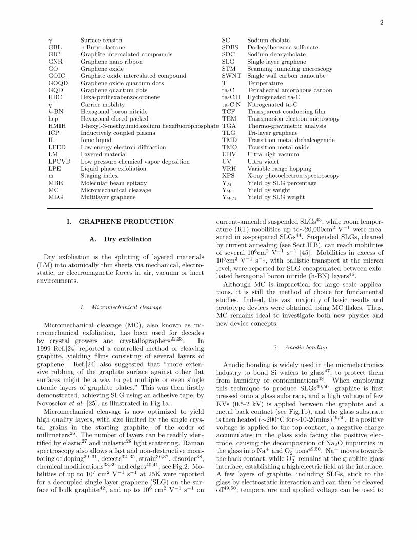
2
γ Surface tension SC Sodium cholateGBL γ-Butyrolactone SDBS Dodecylbenzene sulfonateGIC Graphite intercalated compounds SDC Sodium deoxycholateGNR Graphene nano ribbon SLG Single layer grapheneGO Graphene oxide STM Scanning tunneling microscopyGOIC Graphite oxide intercalated compound SWNT Single wall carbon nanotubeGOQD Graphene oxide quantum dots T TemperatureGQD Graphene quantum dots ta-C Tetrahedral amorphous carbonHBC Hexa-perihexabenzocoronene ta-C:H Hydrogenated ta-Cη Carrier mobility ta-C:N Nitrogenated ta-Ch-BN Hexagonal boron nitride TCF Transparent conducting filmhcp Hexagonal closed packed TEM Transmission electron microscopyHMIH 1-hexyl-3-methylimidazolium hexafluorophosphate TGA Thermo-gravimetric analysisICP Inductively coupled plasma TLG Tri-layer grapheneIL Ionic liquid TMD Transition metal dichalcogenideLEED Low-energy electron diffraction TMO Transition metal oxideLM Layered material UHV Ultra high vacuumLPCVD Low pressure chemical vapor deposition UV Ultra violetLPE Liquid phase exfoliation VRH Variable range hoppingm Staging index XPS X-ray photoelectron spectroscopyMBE Molecular beam epitaxy YM Yield by SLG percentageMC Micromechanical cleavage YW Yield by weightMLG Multilayer graphene YWM Yield by SLG weight
I. GRAPHENE PRODUCTION
A. Dry exfoliation
Dry exfoliation is the splitting of layered materials(LM) into atomically thin sheets via mechanical, electro-static, or electromagnetic forces in air, vacuum or inertenvironments.
1. Micromechanical cleavage
Micromechanical cleavage (MC), also known as mi-cromechanical exfoliation, has been used for decadesby crystal growers and crystallographers22,23. In1999 Ref.[24] reported a controlled method of cleavinggraphite, yielding films consisting of several layers ofgraphene. Ref.[24] also suggested that ”more exten-sive rubbing of the graphite surface against other flatsurfaces might be a way to get multiple or even singleatomic layers of graphite plates.” This was then firstlydemonstrated, achieving SLG using an adhesive tape, byNovoselov et al. [25], as illustrated in Fig.1a.
Micromechanical cleavage is now optimized to yieldhigh quality layers, with size limited by the single crys-tal grains in the starting graphite, of the order ofmillimeters26. The number of layers can be readily iden-tified by elastic27 and inelastic28 light scattering. Ramanspectroscopy also allows a fast and non-destructive moni-toring of doping29–31, defects32–35, strain36,37, disorder38,chemical modifications33,39 and edges40,41, see Fig.2. Mo-bilities of up to 107 cm2 V−1 s−1 at 25K were reportedfor a decoupled single layer graphene (SLG) on the sur-face of bulk graphite42, and up to 106 cm2 V−1 s−1 on
current-annealed suspended SLGs43, while room temper-ature (RT) mobilities up to∼20,000cm2 V−1 were mea-sured in as-prepared SLGs44. Suspended SLGs, cleanedby current annealing (see Sect.II B), can reach mobilitiesof several 106cm2 V−1 s−1 [45]. Mobilities in excess of105cm2 V−1 s−1, with ballistic transport at the micronlevel, were reported for SLG encapsulated between exfo-liated hexagonal boron nitride (h-BN) layers46.Although MC is impractical for large scale applica-
tions, it is still the method of choice for fundamentalstudies. Indeed, the vast majority of basic results andprototype devices were obtained using MC flakes. Thus,MC remains ideal to investigate both new physics andnew device concepts.
2. Anodic bonding
Anodic bonding is widely used in the microelectronicsindustry to bond Si wafers to glass47, to protect themfrom humidity or contaminations48. When employingthis technique to produce SLGs49,50, graphite is firstpressed onto a glass substrate, and a high voltage of fewKVs (0.5-2 kV) is applied between the graphite and ametal back contact (see Fig.1b), and the glass substrateis then heated (∼200C for∼10-20mins)49,50. If a positivevoltage is applied to the top contact, a negative chargeaccumulates in the glass side facing the positive elec-trode, causing the decomposition of Na2O impurities inthe glass into Na+ and O−
2 ions49,50. Na+ moves towardsthe back contact, while O−
2 remains at the graphite-glassinterface, establishing a high electric field at the interface.A few layers of graphite, including SLGs, stick to theglass by electrostatic interaction and can then be cleavedoff49,50; temperature and applied voltage can be used to

3
FIG. 1. Schematic illustration of the main graphene production techniques. (a) Micromechanical cleavage. (b) Anodicbonding. (c) Photoexfoliation. (d) Liquid phase exfoliation.(e) Growth on SiC. Gold and grey spheres represent Si and Catoms, respectively. At elevated T, Si atoms evaporate (arrows), leaving a carbon-rich surface that forms graphene sheets.(f) Segregation/precipitation from carbon containing metal substrate. (g) Chemical vapor deposition. (h) Molecular Beamepitaxy. (i) Chemical synthesis using benzene as building block
control the number of layers and their size49,50. Anodicbonding has been reported to produce flakes up to abouta millimeter in width49.
3. Laser ablation and photoexfoliation
Laser ablation is the use of a laser beam to remove ma-terial from a solid surface51. If the irradiation results intothe detachment of an entire or partial layer, the processis called photoexfoliation52.Laser pulses can in principle be used to ablate/exfoliate
graphite flakes, Fig.1(c). Indeed, tuning the energy den-sity permits the accurate patterning of graphene53. Theablation of a defined number of layers can be obtainedexploiting the energy density windows required for ablat-ing a SLG53 and N-layer graphene (NLGs) of increasingnumber of layers53. Ref.[53] reported that energy densityincreases for decreasing N up to∼7LG. Ref.[53] arguedthat the N dependence of the energy density is related
to the coupling of heat with NLGs via phonons, withthe specific heat scaling as 1/N. For N>7 the ablationthreshold saturates53.Laser ablation is still in its infancy53,54, and needs fur-
ther development. The process is best implemented ininert or vacuum conditions55,56 since ablation in air tendsto oxidize the graphene layers53. Promising results wererecently demonstrated also in liquids57.
B. Liquid-Phase-Exfoliation (LPE)
Graphite can also be exfoliated in liquid environ-ments exploiting ultrasounds to extract individual lay-ers, Fig.1d. The liquid-phase exfoliation (LPE) processgenerally involves three steps: 1) dispersion of graphitein a solvent; 2) exfoliation; 3) ”purification”. The thirdstep is necessary to separate exfoliated from un-exfoliatedflakes, and is usually carried out via ultracentrifugation.The LPE yield can be defined in different ways. The

4
FIG. 2. (a) Optical micrograph of MC flake, consisting ofregions of different thickness. (b) Evolution of Raman spectrawith number of layers28. The spectra are normalized to havethe same G peak intensity.
yield by weight, YW [%], is defined as the ratio betweenthe weight of dispersed graphitic material and that ofthe starting graphite flakes58. The yield by SLG percent-age, YM [%], is defined as the ratio between the numberof SLG and the total number of graphitic flakes in thedispersion58. The Yield by SLG weight, YWM [%], isdefined as the ratio between the total mass of dispersedSLG and the total mass of all dispersed flakes. YW doesnot give information on the the amount of SLG, but onlythe total amount of graphitic material. YM [%], YWM
[%] are more suitable to quantify the dispersed SLGs.
In order to determine YW it is necessary to calculatethe concentration c [g L−1] of dispersed graphitic mate-rial. c is usually determined via optical absorption spec-troscopy (OAS)58–63, exploiting the Beer-Lambert Law:A=αcl, where l [m] is the length of the optical path andα [L g−1 m−1] is the absorption coefficient. α can beexperimentally determined by filtering a known volumeof dispersion, e.g. via vacuum filtration, onto a filter ofknown mass58–61, and measuring the resulting mass us-ing a microbalance. The filtered material is made up of agraphitic mass, surfactant or solvents and residual from
the filter58,59. Thermogravimetric (TGA) analysis is usedto determine the weight percentage of graphitic materialin it, thus enabling the measurement of c58–61. How-ever, different values of α have been estimated both foraqueous59,60 and non-aqueous dispersions58,61. Ref.[58]derived α ∼2460mLmg−1m−1 for a variety of solvents,i.e. N-MethylPyrrolidone, NMP, Dimethylformamyde,DMF, Benzyl benzoate, γ-Butyrolactone, GBL, etc.,while later Ref.[61] reported α ∼3620mL mg−1 m−1 forNMP. Ref.[59] gave α ∼1390mL mg−1 m−1 for aque-ous dispersions with sodium dodecylbenzene sulfonate(SDBS), while Ref.[60] reported∼6600mL mg−1 m−1,still for aqueous dispersions but with sodium cholate(SC). Ref.[60] assigned this discrepancy to the c differ-ence between the two dispersions. However, α cannot bedependent on c (indeed it is used for its determination),thus more work is needed to determine its exact value.YM is usually determined via transmission electron mi-
croscopy (TEM) and atomic force microscopy (AFM). InTEM, N can be counted both analyzing the edges28 of theflakes and by using electron diffraction patterns28. AFMenables the estimation of N by measuring the height ofthe deposited flakes and dividing by the graphite inter-layer distance. However, the estimation for the height ofSLG via AFM is dependent on the substrate. Indeed, forSiO2 a SLG has an height of ∼1nm25, while on mica is∼0.4nm64. Raman spectroscopy is used for the determi-nation of YM
58,62,63 and to confirm the results obtainedwith TEM and/or AFM.YWM [%] requires the estimation of SLGs area other
than N58. However, although this is a more accurate pa-rameter (giving quantitative and qualitative informationon SLGs), with respect YW and YM , to characterize adispersion, its determination is very time consuming. In-deed, to the best of our knowledge it was used only once,when it was defined58. However, for a semi-quantitativeevaluation of the dispersion YM and YW must be re-ported if YWM is not.
1. LPE of graphite
Graphene flakes can be produced by exfolia-tion of graphite via chemical wet dispersion fol-lowed by ultrasonication in water59,62,65,66 and organicsolvents58,62,63,67. Ultrasound-assisted exfoliation is con-trolled by hydrodynamic shear-forces, associated withcavitation68, i.e. the formation, growth, and collapse ofbubbles or voids in liquids due to pressure fluctuations68.After exfoliation, the solvent-graphene interaction needsto balance the inter-sheet attractive forces.Solvents ideal to disperse graphene are those that min-
imize the interfacial tension [mN/m] between the liquidand graphene flakes (i.e. the force that minimizes thearea of the surfaces in contact)69 . In general, interfacialtension plays a key role when a solid surface is immersedin a liquid medium69–71. If the interfacial tension be-tween solid and liquid is high, there is poor dispersibility

5
FIG. 3. Sorting of graphite flakes via isopycnic separation. (a) Formation of step gradient by placing a density gradient mediumwith decreasing concentration. (b) Linear density gradient formed via diffusion. (c) During isopycnic separation the graphiteflake-surfactant complexes move along the cuvette, dragged by the centrifugal force, until their isopycnic points. The buoyantdensity of the flake-surfactant complexes increases with number of layers. (d) Photograph of cuvette containing sorted flakes.
of the solid in the liquid69. In the case of graphitic flakesin solution, if the interfacial tension is high, the flakestend to adhere to each other and the work of cohesion be-tween them is high (i.e. the energy per unit area requiredto separate two flat surfaces from contact69), hinderingtheir dispersion in liquid. Liquids with surface tension(i.e. the property of the surface of a liquid that allows itto resist an external force, due to the cohesive nature ofits molecules69) γ∼40mN/m [58], are the ”best” solventsfor the dispersion of graphene, since they minimize theinterfacial tension between solvent and graphene.
Ref.[72] determined via wettability and con-tact angle measurements the surface energy, [mJ/m2], of different graphitic materials, finding ∼46mJ/m2,∼55mJ/m2,∼62mJ/m2 for reducedgraphene oxide (RGO), graphite and graphene oxide(GO). The slight difference being due to the differentsurface structure of GO, RGO and graphite. Ref.[73]reported that contact angle measurements are notaffected by N.
The majority of solvents with γ ∼40mN/m (i.e. NMP,DMF, Benzyl benzoate, GBL, etc.) [see Ref.[58] for acomplete list] have some disadvantages. E.g., NMP maybe toxic for the reproductive organs74, while DMF mayhave toxic effects on multiple organs75. Moreover, allhave high (>450K) boiling points, making it difficultto remove the solvent after exfoliation. As an alterna-tive, low boiling point solvents76, such as acetone, chlo-roform, isopropanol, etc. can be used. Water, the ”nat-ural” solvent, has γ ∼72mN/m [69], too high (30mN/mhigher than NMP) for the dispersion of graphene72 and
graphite72. In this case, the exfoliated flakes can be stabi-lized against re-aggregation by Coulomb repulsion usinglinear chain surfactants, e.g. SDBS59, or bile salts e.g.
SC65 and sodium deoxycholate (SDC)62,66, or polymerse.g. pluronic77, etc. However, depending on the final ap-plication, the presence of surfactants/polymers may bean issue, e.g. compromising, decreasing, the inter-flakeconductivity78.
Thick flakes can be removed by different strategiesbased on ultracentrifugation in a uniform medium79,or in a density gradient medium (DGM)80. The firstis called differential ultracentrifugation (sedimentationbased-separation, SBS)79, while the second is called den-sity gradient ultracentrifugation (DGU)80. The SBS pro-cess separates various particles on the basis of their sedi-mentation rate79 in response to a centrifugal force actingon them. Sedimentation based separation is the mostcommon separation strategy and, to date, flakes rangingfrom few nanometers to a few microns have been pro-duced, with concentrations up to a few mg/ml61,81. Highconcentration is desirable for large scale production ofcomposites58 and inks63. YM up to ∼70% were achievedby mild sonication in water with SDC, followed by SBS66,while YM ∼33% was reported with NMP63. This YM dif-ference is related to the difference in flake lateral size. Inwater-surfactant dispersions flakes are on average smaller(∼30nm66 to∼200nm59) than in NMP(∼1µm58,63), sincethe viscosity (ν) at RT of NMP (1.7mPas82) is higherthan water (∼1mPas82). Larger flakes in a higher viscos-ity medium experience a higher frictional force79,80 thatreduces their sedimentation coefficient, making it more
6
difficult for them to sediment. This decreases YM inNMP compared to water.
During DGU, the flakes are ultracentrifuged in a pre-formed DGM80,83, see Figs.3a,b, where they move alongthe cuvette until they reach the corresponding isopyc-nic point, i.e., the point where their buoyant densityequals that of the surrounding DGM80. The buoyantdensity is defined as the density (ρ) of the medium atthe corresponding isopycnic point80,83. Isopycnic separa-tion was used to sort nanotubes by diameter84,85, metal-lic vs semiconducting nature86 and chirality87. However,unlike nanotubes of different diameter, graphitic flakeshave the same density, irrespective of N, so another ap-proach is needed to induce a density difference: coverageof the flakes with a surfactant results in an increase ofbuoyant density with N, Fig.3c. Fig.3d shows a cuvetteafter isopycnic separation. Ref.[65] reported YM ∼80%for this technique with SC surfactant.
Another method is the so-called rate zonal separation(RZS)88. This exploits the difference in sedimentationrates of nanoparticles with different size89, shape90 andmass89, instead of the difference in nanoparticle density,as in the case of isopycnic separation. RZS was used toseparate flakes with different size88 (the larger the size,the larger the sedimentation rate).
Other routes based on wet chemical dispersion havebeen investigated, such as exfoliation in ionic liq-uids (ILs)91,92, 1-hexyl-3-methylimidazolium hexafluo-rophosphate (HMIH)91 or 1-butyl-3-methylimidazoliumbis(trifluoro-methane-sulfonyl)imide ([Bmim]-[Tf2N])92.These are a class of purely ionic, salt-like materials93,defined as salts in the liquid state (below 100C), largelymade of ions93. Ref.[91] reported concentrations ex-ceeding 5mg/mL by grinding graphite in a mortar withILs, followed by ultrasonication and centrifugation. Theflakes had sizes up to∼3-4µm, however no data was shownfor N91. Ref.[91] used a long ultrasonication process(>24 hours), probably because of the IL high viscos-ity. In SBS viscosity plays a fundamental role. Flakesin a higher viscosity medium have a lower sedimenta-tion coefficient with respect to water. The sedimentationcoefficient is commonly measured in Svedberg (S) units(with 1S corresponding to 10−13sec.), the time neededfor particles to sediment out of the fluid, under a cen-trifugal force79. E.g., for a flake dispersed in [Bmim]-[Tf2N] (ρ=1.43g/cm3, ν=32mPas), the sedimentation co-efficient is∼55 times smaller than in water. There are noreports to date showing that exfoliation via ultrasonica-tion in ILs can have the same YM as in water66, or or-ganic solvents63. Moreover, the resultant flakes containoxygen functional groups92, probably due strong non-covalent interactions, or covalent functionalization with[Bmim][Tf2N] itself
92. A step forward for the productionof flakes without these functional groups was reported inRef.[94], where oxygen-free flakes were made by grind-ing graphite in 1-Butyl-3-methylimidazolium hexafluo-rophosphate, [BMIMPF6]. Ionic liquids were then re-moved by mixing with Acetone and DMF92. Controlling
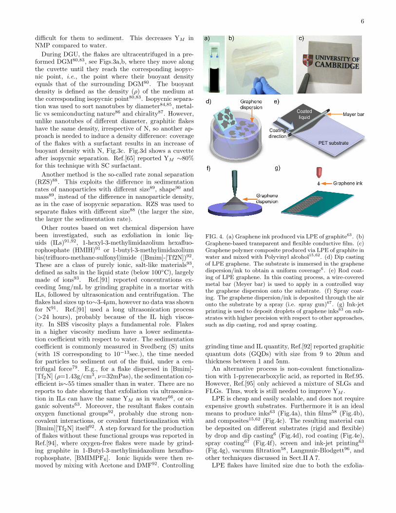
FIG. 4. (a) Graphene ink produced via LPE of graphite63. (b)Graphene-based transparent and flexible conductive film. (c)Graphene polymer composite produced via LPE of graphite inwater and mixed with Polyvinyl alcohol15,62. (d) Dip castingof LPE graphene. The substrate is immersed in the graphenedispersion/ink to obtain a uniform coverage6. (e) Rod coat-ing of LPE graphene. In this coating process, a wire-coveredmetal bar (Meyer bar) is used to apply in a controlled waythe graphene dispersion onto the substrate. (f) Spray coat-ing. The graphene dispersion/ink is deposited through the aironto the substrate by a spray (i.e. spray gun)67. (g) Ink-jetprinting is used to deposit droplets of graphene inks63 on sub-strates with higher precision with respect to other approaches,such as dip casting, rod and spray coating.
grinding time and IL quantity, Ref.[92] reported graphiticquantum dots (GQDs) with size from 9 to 20nm andthickness between 1 and 5nm.An alternative process is non-covalent functionaliza-
tion with 1-pyrenecarboxylic acid, as reported in Ref.95.However, Ref.[95] only achieved a mixture of SLGs andFLGs. Thus, work is still needed to improve YM .LPE is cheap and easily scalable, and does not require
expensive growth substrates. Furthermore it is an idealmeans to produce inks63 (Fig.4a), thin films58 (Fig.4b),and composites15,62 (Fig.4c). The resulting material canbe deposited on different substrates (rigid and flexible)by drop and dip casting6 (Fig.4d), rod coating (Fig.4e),spray coating67 (Fig.4f), screen and ink-jet printing63
(Fig.4g), vacuum filtration58, Langmuir-Blodgett96, andother techniques discussed in Sect.II A 7.LPE flakes have limited size due to both the exfolia-

7
tion procedure, that induces in-plane fracture, and thepurification process, which separates large un-exfoliatedflakes. To date, LPE-SLGs have area mostly below 1µm2
[Refs.58, 59, 61–63, 65, 66, and 76].Liquid phase exfoliation can also be optimized to
produce graphene nanoribbons (GNRs), with widths<10nm97. Ref.[97] ultrasonicated expanded graphite98,i.e. with larger interlayer distance with respect tographite due to intercalation of nitric99 and sulfuricacid100. Expanded graphite was dispersed in a 1,2-dichloroethane solution of poly(m-phenylenevinylene-co-2,5-dioctoxy-p-phenylenevinylene), ultrasonicated andultracentrifuged, resulting in a combination of flakes andGNRs of different shapes. However, the GNR productionmechanism via LPE of graphite is not well understood.Thus, more work is needed to fully understand and im-prove GNRs production via LPE.
2. LPE of graphite oxide
LPE is a versatile technique and can be exploited notonly for the exfoliation of pristine graphite as reportedin Sect.I B 1 but also for the exfoliation of graphite oxideand graphite intercalated compounds (GICs), which havedifferent properties with respect to pristine graphite.The oxidation of graphite in the presence of potassiumchlorate (KClO3) and fuming nitric acid was developedby Brodie in 1859 while investigating the reactivity ofgraphite flakes101. This process involved successive ox-idative treatments of graphite in different reactors101. In1898, Staudenmaier modified Brodie’s process by usingconcentrated sulphuric acid and adding KClO3 in suc-cessive steps during the reaction102. This allowed car-rying out the reaction in a single vessel, streamliningthe production process103. However, both methods weretime consuming and hazardous, as they also yielded chlo-rine dioxide (ClO2) gas
104, which can explosively decom-pose into oxygen and chlorine104. Graphite oxide flakeswere already investigated by Kohlschtter and Haenni in1918105, and the first TEM images reported in 1948 byRuess and Vogt106 showed the presence of single GOsheets. In 1958, Hummers modified the process usinga mixture of sulphuric acid, sodium nitrate and potas-sium permanganate107. Avoiding KClO3 made the pro-cess safer, quicker, with no explosive byproducts107.These aggressive chemical processes disrupt the sp2-
bonded network and introduce hydroxyl or epoxidegroups108–110 in the basal plane, while carbonyl andcarboxylic groups, together with lactone, phenol andquinone attach to the edges (see Fig.5). However, theintroduction of these functional groups is essential forthe GO production and subsequent liquid dispersion.GO flakes can be prepared via sonication97,111,
stirring112, thermal expansion113, etc., of graphite oxide.The aforementioned functional groups make GO flakesstrongly hydrophilic, allowing their dispersion in purewater97,111, organic solvents112–114, aqueous mixtures
with methanol, acetone, acetonitrile115 or 1-propanoland ethylene glycol116. However, although large GOflakes, up to several microns117, can be produced, theyare defective108 and insulating, with sheet resistance(Rs)∼1012Ω/, or higher118.
GO is luminescent under continuous waveirradiation119. Visible excitation gives a broadphotoluminescence (PL) spectrum from visible tonear-infrared120, while blue emission121 is detectedupon ultraviolet (UV) excitation. This makes GO aninteresting material for lighting applications (e.g. lightemitting devices122) and bio-imaging120.
Several processes have been developed to chemi-cally ”reduce” the GO flakes, i.e. decrease the ox-idation state of the oxygen-containing groups in or-der to re-establish an electrical and thermal con-ductivity as close as possible to pristine graphene.In 1962, the reduction of graphite oxide in alka-line dispersions was proposed for the production ofthin (down to single layer) graphite lamellaes110,123.Other methods involve treatments by hydrazine97,124,hydrides116,125, p-phynylene126, hydroquinone125 etc, aswell as dehydration127 or thermal reduction108,113,128.UV-assisted photocatalyst reduction of GO was alsoproposed129, whereby GO reduces as it accepts electronsfrom UV irradiated TiO2 nanoparticles129.
The charge transport in RGO is believed to takeplace via variable-range hopping (VRH)121,130. Indi-vidual RGO sheets have been prepared with electricalconductivity (σ) ∼350Scm−1 [131], while higher val-ues (1314Scm−1) were achieved in thin films132, be-cause in the latter RGO flakes are equivalent to re-sistors in parallel124. These σ are much bigger thanorganic semiconductors (e.g. poly(β’-dodecyloxy(-α,α’-α’,α”-)terthienyl) (poly(DOT)) ∼10−3Scm−1 for a sam-ple doped to∼1021cm−3)133.
It is important to differentiate between dispersion-processed flakes, retaining the graphene electronic prop-erties, such as those reported in Refs.[58, 59, 61–63, 65–67], and GO flakes, such as those in Refs.[97, 111–114].Indeed, GO can have σ as low as∼10−5Scm−1[97], whileLPE graphene can feature σ up to∼104Scm−1 [67].
GO and RGO can be deposited on different substrateswith the same techniques used for LPE graphene, dis-cussed in Sect.[II A 7]. GO and RGO are ideal forcomposites134, due the presence of functional groups,which can link polymers134.
Ref.[135] reported RGO sheets with σ ∼103Sm−1, highflexibility, and surface areas comparable to SLG, thusinteresting for a range of electronic and optoelectronicapplications. Thin films of RGO have been tested asfield-effect transistors (FETs)136, transparent conductingfilms (TCFs)137, electro-active layers138, solar cells139,ultrafast lasers140,141, etc. Patterning has been used tocreate conductive RGO-based electrodes121.

8
FIG. 5. GO synthesis and reduction. Graphite can be oxidized with different procedures in the presence of strong acids. TheGO flakes have the plane functionalized with epoxy and hydroxyl groups both above and below and at the edges115,121. Apartial recovery of the electronic properties can be reached following a reduction treatment97,108,112–115. However, none of thecurrent approaches can fully remove the defects.
FIG. 6. Graphite intercalation compounds. In stage 1, SLGalternate with intercalant layers. In stage 2, stage 3, etc, 2,3, etc. graphene layers separate two intercalant layers
3. LPE of intercalated graphite
GIC are formed by periodic insertion of atomicor molecular species (intercalants) between graphitelayers142–144. GICs are classified in terms of ”staging”index m, i.e. the number of graphene layers between twointercalant layers. Thus, e.g., a stage 3 GIC (see Fig.6)has each 3 adjacent graphene layers sandwiched by 2 in-tercalant layers142 (the latter can also be more than 1atom thick).Ref.[142 and 143] summarized the historical develop-
ment of GICs. The production of GICs started in themid-1800s with the seminal work of Schaffautl in 1841145.The first m determination by X-Ray diffraction was donein 1931 by Hoffman and Fenzel146. Systematic studiesstarted in the late 1970s.Intercalation of atoms or molecules with different m
gives rise to a wide variety of electrical142, thermal142 andmagnetic properties142. GICs have potential as highlyconductive materials142,147–149. GICs with metal chlorideor pentafluoride intercalants, such as Antimony pentaflu-oride (SbF5) and Arsenic pentafluoride (AsF5), receivedmuch interest since the 1970s142,147–149. E.g., AsF5
GICs has slightly higher σ (6.3×10⁵Scm−1)147 than bulkCu148,149 (5.9×10⁵Scm−1)147, while the graphite in planeσ is∼4.5×10⁴Scm−1 [150]. The σ increase is assigned toinjection of carriers from the intercalate layer, with lowmobility, to the graphite layers, with high mobility142.
GICs can be superconducting151 with transition tem-peratures up to 11.5K for CaC6 GICs at ambientpressure152, and higher with increasing pressure153.GICs are also promising for hydrogen storage, due to alarger interlayer spacing154. GICs are already commer-cialized in batteries155, in particular, in Li-ion batteriessince the 1970s156–159. GICs have also been used as neg-ative electrodes (anode during discharge) in Li-ion bat-teries with the introduction of solid electrolytes160,161.
A number of approaches have been developed overthe years for GIC production, starting from solid162,liquid163 or gaseous reagents164. Intercalation requires ahigh vapor pressure (i.e.∼3-5atm) to enable intercalantsto penetrate between the graphite layers142,164. Themost common production strategies include two-zone va-por transport142,162,165, exploiting T differences betweengraphite and intercalants164 and, sometimes, the pres-ence of gases164, e.g. Cl2 for intercalation of AlCl3
142.GICs can be produced in single (for binary or ternaryGICs) or multiple steps, the latter when direct interca-lation is not possible166. Hundreds of GICs with donor(alkali, alkali earth metals, lanthanides, metal alloys orternary compounds, etc.) or acceptor intercalants (i.e.halogens, halogen mixtures, metal chlorides, acidic ox-ides, etc.) have been reported142,165.
The intercalation process increases the graphite inter-layer spacing, especially for low stage index GICs167,168.E.g., K, Rb or Cs-GICs have interlayer distance∼0.53-0.59nm, while larger intercalants, such as dimethylsul-foxide, give an interlayer distance∼0.9nm168, i.e. 1.5to∼3 times larger than the∼0.34nm spacing in pris-tine graphite. This makes GICs promising startingmaterials to produce graphene via LPE, even without

9
ultrasonication64,167–170. However, although the exfolia-tion process is often called spontaneous64,170, due to theabsence of an ultrasonication step, it requires mechani-cal energy, often provided by stirring64,170. To date it ispossible to exfoliate GICs with lateral sizes∼20µ,m withYM ∼90%169, and mobilities of ∼tens cm2V−1[169].Note that many GICs tend to oxidize in air142,171, and
require a controlled ambient for their processing142,171.This, coupled with the additional steps for GIC produc-tion, is one of the primary reasons why GICs are not yetextensively used to produce graphene via LPE. However,Ref.[172] recently reported FeCl3 intercalated FLGs air-stable for up to one year.
C. Growth on SiC
The production of graphite from SiC, Fig.1e, was re-ported by Acheson as early as 1896 (Ref.173) for lu-bricant applications173. The growth mechanism hasbeen investigated since the 1960s174,175. Both surfaces(Si(0001)- and C(000-1)-terminated) annealed at hightemperature (>1000C) under ultra-high vacuum (UHV)graphitize due to the evaporation of Si176,177. Refs.[178and 179] reported the production of graphene films bythermal decomposition of SiC above 1000C. Thermaldecomposition is not self-limiting179, and areas of differ-ent thicknesses may exist on the same SiC crystal179.On the Si(0001)-face, graphene grows on a C-rich
6√3 × 6
√3 R30 reconstruction with respect to the
SiC surface180, called ”buffer layer”180. This consistsof C atoms arranged in a graphene-like honeycombstructure180, but without graphene-like electronic prop-erties, because∼30% are covalently bonded to Si180,181.The buffer layer can be decoupled from the Si(0001)-
face by hydrogen intercalation182–184 becoming a quasi-free-standing SLG with typical linear π bands182.Growth of graphene on SiC is referred to as ”epitaxial
growth”185 even though there is a very large lattice mis-match between SiC (3.073A) and graphene (2.46A), andcarbon rearranges in a hexagonal structure as Si evapo-rates from the SiC substrate, rather than being depositedon the SiC surface as would happen in a traditional epi-taxial growth process. The term ”epitaxy” derives fromthe Greek, the prefix epi means ”over” or ”upon” andtaxis means ”order” or ”arrangement”. In 1928 Royer[186] used the term ”epitaxy” referring to the ”orientedgrowth of one substance on the crystal surface of a foreignsubstance”. If the growing crystal and the substrate havethe same lattice constants these are lattice matched187.The use of ”epitaxial” as the adjectival form of epitaxyhas been subjected to some criticism already in the six-ties, because it is incorrect from the philological point ofview188. Epitactic is the correct form188. In 1965 epitaxicwas recommended by Ref.[189]. However, the word ”epi-taxial” is now widely used, and any attempt to changeit is unrealistic. We will thus use ”epitaxial” as adjec-tival form of epitaxy. There are two epitaxial processes,
depending on the substrate: homo- and hetero-epitaxy.In the case of homoepitaxy the substrate is of the samecomposition and structure as the growing film, whereasin heteroepitaxy the substrate is of a different composi-tion, and may not be perfectly lattice matched.
It would be desirable to grow graphene on a latticematched isostructural substrate, in order to minimizedefects, like misfit dislocations, as in the case of tradi-tional semiconductors190. However, with the exceptionof graphite, where the growth would be referred to ashomoepitaxy and is not useful or practical for obviousreasons, there are few substrates that are isostructuraland nearly lattice matched with graphene. There aretwo potential subtrates that might meet the aforemen-tioned requirement, h-BN and hexagonal closed packed(hcp) Co. h-BN has the lowest lattice mismatch∼1.7%.Cobalt metal (hcp at T<400C) also has a small latticemismatch∼2%. There are other hcp metals like Ru, Hf,Ti, Zr but these have much larger lattice mismatch191
than that between Co and graphene. Face center cu-bic metals like Ni, Cu, Pd, Rh, Ag, Au, Pt and Irhave a range of lattice mismatch on the (111) planes.Therefore, from an epitaxial growth perspective, it wouldbe desirable to grow on oriented single crystal Co (seeSect.I D,I E) as performed by Ref.192. Growth on Cowould also require transfer to other non-metallic sub-trates, as discussed later. SiC could be ideal, were it notfor the fact that the lattice mismatch between grapheneand SiC is also very large,∼25%, both for 4H-SiC (Si-face) and 6H-SiC (C-face). Perhaps it is not appropriateto call graphene growth on SiC epitaxial, but this is whatnumerous papers do. There have been reports of growthof layered materials on highly non-lattice-matched sub-strates as buffer layers, due to their weak bonding to theunderlying substrates193–195. In this case the films growparallel to the substrate because of the anisotropic na-ture of their chemical bonds. Growth of graphene on SiCmight be described in a similar manner193–195.
The growth rate of graphene on SiC depends on thespecific polar SiC crystal face196,197. Graphene formsmuch faster on the C- than on the Si-face196,197. Onthe C-face, larger domains (∼200nm) of multilayered, ro-tationally disordered graphene are produced198,199. Onthe Si-face, UHV annealing leads to small domains,∼30-100nm198,199. The small-grain structure is attributed tomorphological changes of the surface during annealing179.
Different strategies have been proposed to control theSi sublimation rate. Ref.[200] used Si vapors to establishthermodynamic equilibrium between SiC and external Sivapor, in order to vary the transition T from the Si-rich(3×3) to the C-rich (6
√3×6
√3R30) phase, and final
graphene layer. The resulting domains were an order ofmagnitude larger than those grown under UHV182.
Ref.[179] used the ”light bulb method” to growgraphene, exploiting a 80-year old process first devel-oped to extend the lifetime of incandescent lightbulbfilaments201. This uses Ar in a furnace at near ambi-ent pressure (1 bar) to reduce the Si sublimation rate.
10
Indeed, in Ar no sublimation is observed until 1500C,whereas Si desorption starts at 1150C in UHV179, thusenhancing surface diffusion, with complete surface re-structuring before graphene formation179. The resultingfilms on the Si-face have∼50µm domains179, almost 3 or-ders of magnitude larger than in UHV annealing198,199.Si sublimation can also be controlled by confining SiC
in an enclosure (either in vacuum196 or inert gas196) lim-iting Si escape, maintaining a high Si vapor pressure.This keeps the process close to thermodynamic equilib-rium, resulting in either SLG196 or FLG196 over large(cm scale) areas, both on Si-[196] and C-faces[196]. HighT annealing of SiC can also give GNRs and GQDs202,203.To date, graphene grown on the Si-face has a RT mo-
bility up to∼500-2000cm2V−1s−1[196], with higher val-ues on the C-face (∼10000-30000cm2V−1s−1)196,197,199.For near-intrinsic samples (8.5×1010cm−2)204 RT mo-bilities up to∼150000cm2V−1s−1 on the C-face205
and∼5800cm2V−1s−1 on the Si-face205 were reported.Graphene on SiC has the benefit that SiC is an estab-
lished substrate for high frequency electronics206, lightemitting devices206, and radiation hard devices206. Top-gated transistors have been fabricated from grapheneon SiC on a wafer scale207. High frequency transis-tors have also been demonstrated with 100GHz cut-offfrequency208, higher than state-of-the-art Si transistorsof the same gate length209. Graphene on SiC has beendeveloped as a novel resistance standard based on thequantum Hall effect (QHE)2,3,210.A drawback for this technology to achieve large scale
production equivalent to that in the present Si technol-ogy, is the SiC wafers cost (∼ $150-250 for 2”211 at 2011prices, compared to∼ $5-10 for same size Si) and theirsmaller size (usually no larger than 4”211) compared toSi wafers. One approach to reduce substrate costs is togrow thin SiC layers on sapphire, the latter costing lessthan∼ $10 for 2”212, and subsequently perform thermaldecomposition to yield FLG213. Thus far, FLGs pro-duced in this way have inferior structural and electronicquality compared to those on bulk SiC. Another approachis to grow SiC on Si214. However SiC on Si is usuallycubic215–218, making it challenging to achieve continuoushigh quality graphene, due to bowing and film crackingas a consequence of high residual stress219,220. Ref.[221]grew SLG on 3C-SiC(111) with domains∼100µm2, bycombining atmospheric pressure growth179 with hydro-gen intercalation183, demonstrating that large area do-mains can also be grown on 3C-SiC(111).
D. Growth on metals by precipitation
The first reports of synthetic growth of graphite, i.e.not extracted from mined natural sources, on transitionmetals date back to the early 1940s222,223. However, thedetails of the growth process were not elucidated un-til the 1970s, when Shelton et al.[224] identified, via acombination of Auger and low-energy electron diffraction
(LEED), SLG formed from carbon precipitation, follow-ing high T annealing of Co, Pt, Ni. Graphite can also beobtained from carbon saturated molten Fe during the for-mation of steel225. In this process, Fe is supersaturatedwith carbon, and the excess carbon precipitates225. Thisis usually referred to as ”Kish graphite”226, from the Ger-man ”Kies”, used by steel workers to refer to the ”mix-ture of graphite and slag separated from and floating onthe surface of molten pig iron or cast iron as it cools”227.
The amount of carbon that can be dissolved in mostmetals is up to a few atomic percent228. In order toeliminate the competition between forming a carbide andgraphite/graphene growth, the use of non-carbide form-ing metals, e.g. Cu, Ni, Au, Pt, Ir, is preferred229. Ele-ments like Ti, Ta, Hf, Zr and Si, etc. form thermally sta-ble carbides, as shown by the phase diagram230–234, thusare not ”ideal” for graphite/graphene growth. Moreover,all have a large (>20%) lattice mismatch with graphene.
Carbon can be deposited on the metal surface by anumber of techniques, flash evaporation, physical va-por deposition (PVD), chemical vapor deposition (CVD),spin coating. The carbon source can be a solid235,236,liquid237–239 or gas240. In the case of pure carbon, flashevaporation241 or PVD242, can be used to deposit carbondirectly on the substrate of interest, before diffusion athigh T, followed by precipitation of graphite (graphene)upon cooling. When the solid source is a polymer, it canbe spun on the metal substrate at RT, followed by highT annealing and growth236, as mentioned above.
The growth process on Ni was first investigated in 1974in Ref.[224]. They observed SLG on Ni(111) at T>1000Kby Auger analysis, followed by graphite formation uponcooling. During high T annealing, carbon diffuses intothe metal until it reaches the solubility limit. Uponcooling, carbon precipitates forming first graphene, seeFig.1f, then graphite224. The graphite film thickness de-pends on the metal, the solubility of carbon in that metal,the T at which the carbon is introduced, the thickness ofthe metal and the cooling rate.
There has been an effort to try and use inexpensivemetals to grow large area (cm scale) graphene, such asNi243–246 and Co247 , while growth on noble metals suchas Ir248, Pt249, Ru250–253, and Pd249,254, was performedprimarily to study the growth mechanism255–259, and/orobtain samples suitable for fundamental studies, e.g. forscanning tunneling microscopy (STM)252,253,260, requir-ing a conductive substrate.
Growth of graphene on Ni243–246,261, Co247, Ru251,etc. was also reported by so-called chemical vapor de-position at high temperature, using various hydrocarbonprecursors243–247. However, the CVD process referredto in the aforementioned papers is a misnomer, sincegraphene is not directly produced on the metal surfaceby the reaction and deposition of the precursor at the”growth T”, but rather grows by carbon segregation fromthe metal bulk, as a result of carbon supersaturation inthe solid, as discussed above224,240.
For lattice mismatches between graphene and sub-

11
strate below 2%, commensurate superstructures, wherethe resulting symmetry (between graphene and sub-strate) is a doubling of the unit cell along one axis (i.e.1/2, 0,0), are formed261. This is the case in Co(0001)262.Larger mismatches yield incommensurate (i.e. with totalloss of symmetry in a particular direction, i.e.(0.528,0,0))Moire superstructures, such as in Pt(111)263, Ir(111)264,or Ru(0001)255. E.g., high-T segregation of C onRu(0001) gives a spread of orientations255. Also, thegraphene/Ru lattice mismatch260 gives a distribution oftensile and compressive strains265, thus causing corruga-tion, with a roughness∼2A265. The Moire superstructurecould be eliminated by adsorption of oxygen266, since thisweakens the graphene interaction with the substrate266.Growth of graphene by precipitation requires careful
control of the metal thickness, T, annealing time, cool-ing rate, and metal microstructure. Recently, Ref.[251]reported growth on Ni, Co and Ru on sapphire. Throughthe suppression of grain boundaries, Ref.[251] demon-strated uniform growth on Ru by a surface catalyzed re-action of hydrocarbons, but not on Ni and Co251. BothSLG and FLG were observed on Ni and Co, presumablydue to the higher solubility of carbon and incorporationkinetics in comparison to Ru at the same T251. How-ever, Ref.[192] grew graphene on epitaxial Co on sap-phire, achieving SLGs, in contrast to FLGs in Ref.[251].An alternative strategy for SLG growth on high C solubil-ity substrates was proposed by Ref.[267], using a binaryalloy (Ni-Mo). The Mo component of the alloy traps allthe dissolved excess C atoms, forming molybdenum car-bides and suppressing C precipitation267. Graphene wasalso grown on epitaxial Ru(0001) on sapphire268.One of the shortcomings of the growth on metals is
that most applications require graphene on an insulat-ing substrate. Ref.[269] suggested that graphene can begrown directly on SiO2 by the precipitation of carbonfrom a Ni film deposited on the dielectric surface. Thisprocess has promise but needs further refinement.
E. Chemical vapor deposition (CVD)
CVD is a process widely used to deposit or grow thinfilms, crystalline or amorphous, from solid, liquid orgaseous precursors of many materials. CVD has been theworkhorse for depositing many materials used in semi-conductor devices for several decades270.The type of precursor is usually dictated by what is
available, what yields the desired film, and what is costeffective for the specific application. There are manydifferent types of CVD processes: thermal, plasma en-hanced (PECVD), cold wall, hot wall, reactive, and manymore. Again, the type depends on the available precur-sors, the material quality, the thickness, and the struc-ture needed, plus it is important to keep in mind thatcost is an essential part of selecting a specific process.The main difference in the CVD equipment for the dif-
ferent precursor types is the gas delivery system271. In
the case of solid precursors, the solid can be either vapor-ized and then transported to the deposition chamber271,or dissolved using an appropriate solvent271, delivered toa vaporizer271, and then transported to the depositionchamber271. The transport of the precursor can also beaided by a carrier gas271. Depending on the desired de-position T, precursor reactivity, or desired growth rate, itmay be necessary to introduce an external energy sourceto aid precursor decomposition.One of the most common and inexpensive production
methods is PECVD. The creation of plasma of the re-acting gaseous precursors allows deposition at lower Twith respect to thermal CVD. However, since plasmacan damage the growing material, one needs to designthe equipment and select process regimes that minimizethis damage. The details of the growth process are usu-ally complex, and in many cases not all of the reactionsare well understood. There are many different ways toperform plasma assisted CVD and it is not the objectiveof this review to cover all of them (see Ref.[272] for anoverview). It is however important to match the equip-ment design with the material one is trying to depositand the precursor chemistry. Graphene should be sim-pler than multi-component systems, since it is a single el-ement material. As with many other materials, graphenegrowth can be performed using a wide variety of pre-cursors, liquids, gases, solids, growth chamber designs,thermal-CVD or PECVD, over a wide range of chamberpressures and substrate T. In the next sections we willdescribe CVD of graphene on metals and dielectrics.
1. Thermal CVD on metals
In 1966 Karu and Beer[240] used Ni exposed tomethane at T=900C to form thin graphite, to be usedas sample support for electron microscopy. In 1971,Perdereau and Rhead273 observed the formation of FLGvia evaporation of C from a graphite rod273. In 1984Kholin et al.[274] performed what may be the first CVDgraphene growth on a metal surface, Ir, to study thecatalytic and thermionic properties of Ir in the presenceof carbon275. Since then, other groups exposed metals,such as single crystal Ir261,276, to carbon precursors andstudied the formation of graphitic films in UHV systems.The first studies of graphene growth on metals pri-
marily targeted the understanding of the catalytic andthermionic activities of the metal surfaces in the presenceof carbon277. After 2004, the focus shifted to the actualgrowth of graphene. Low pressure chemical vapor depo-sition (LPCVD) on Ir(111) single crystals using an ethy-lene precursor was found to yield graphene structurallycoherent even over the Ir step edges261. While Ir cancertainly be used to grow graphene by CVD, see Fig.1g,because of its low carbon solubility228, it is difficult totransfer graphene to other substrates because of its chem-ical inertness. Ir is also very expensive. Growth on Ni243
and Co247,278, metals compatible with Si processing since

12
they have been used for silicides for over a decade279–283,and less expensive than Ir, poses a different challenge,i.e. FLGs are usually grown240,243–247,276, and SLGsgrow non-uniformly, as described in Sect.I D. Therefore,while many papers claim CVD growth at high T on Niand Co240,243–247,276, the process is in fact carbon pre-cipitation, not yielding uniform SLG, rather FLGs. Theshortcoming of high solubility or expensive and chemi-cally unreactive metals motivated the search for processesand substrates better suited to yield SLG.
The first CVD growth of uniform, large area (∼cm2)graphene on metal was in 2009 by Ref.[229] on polycrys-talline Cu foils, exploiting thermal catalytic decomposi-tion of methane and low carbon solubility. This processis almost self-limited, i.e. growth is suppressed as soonas the Cu surface is fully covered with graphene, butstill with∼5% BLG and 3LG229,284. Large area graphenegrowth was enabled principally by the low C solubility inCu285, and Cu mild catalytic activity286.
Growth of graphene on Cu by LPCVD was thenscaled up in 2010 by Ref.[9], increasing the Cufoil size (30 inches), producing films with mo-bility (η)∼7350cm2V−1s−1 at 6K. Large grain,∼20-500µm, graphene on Cu with η ranging from∼16,400to∼25,000cm2V−1s−1 at RT after transfer to SiO2
was reported in Refs.[287 and 288], and from∼27,000to∼45,000cm2V−1s−1 on h-BN at RT287.
The current understanding of the growth mechanismis as follows. Carbon atoms, after decomposition fromhydrocarbons, nucleate on Cu, and the nuclei grow intolarge domains288,289. The nuclei density is principally afunction of T and pressure and, at low precursor pres-sure, mTorr, and T>1000C, very large single crystaldomains,∼0.5mm are observed288,289. However, whenthe Cu surface is fully covered, the films become polycrys-talline, since the nuclei are not registered229,288,289,i.e.they are mis-oriented or incommensurate with respect toeach other, even on the same Cu grain. This could beascribed to the low Cu-C binding energy290. It wouldbe desirable to have substrates such as Ru, with higherbinding energy with C290. However, while Ru is compat-ible with Si processing291, oriented Ru films may be dif-ficult to grow on large (300-450mm) diameter Si wafers,or transferred from other substrates.
There are some difficult issues to deal with whengrowing graphene on most metal substrates, especiallyCu, because of the difference in thermal expansion co-efficient between Cu and graphene, of about an or-der of magnitude292. The thermal mismatch givesrise to a significant wrinkle density upon cooling284.These wrinkles are defective, as determined by Ramanspectroscopy288, and may also cause significant devicedegradation through defect scattering, similar to the ef-fect of grain boundaries on mobility in semiconduct-ing materials288. These defects however, may not bedetrimental for many non-electrically-active applications,such as transparent electrodes. Perhaps one could usecheaper substrates, such as Cu (Cu is cheaper than Ir,
Ru, Pt) and use an electrochemical process to removegraphene while reusing Cu, so that the cost is amortizedover many growth runs. Because of some unattractiveproperties (e.g. surface roughening and sublimation) ofCu at the current thermal CVD growth T>1000C, thecommunity has been searching for new substrates thattake advantage of the self-limited growth process, in ad-dition to dielectrics. Ref.[293] reported growth of SLG onNi(111) at lower T, 500-600C, using ethylene by UHVCVD, and identified the process as self-limiting, presum-ably due to the low C solubility in Ni at T<650C294.However, the T range within which graphene can begrown on Ni is very narrow, 100C293, and could re-sult in a Ni2C phase293, which can give rise to defectswithin the Ni crystal. Thus one could surmise that anygraphene growing on the surface could be non-uniformacross the Ni-Ni2C regions.
Graphene was also grown on Cu by exposing it toliquids or solid hydrocarbons236,295. Ref.[295] reportedgrowth using benzene in the T range 300-500C.
The process space for SLG-CVD growth is very wideand depends on many factors, from substrate choice, tospecific growth conditions, as well as variables not underdirect control. It is critical to know the material require-ments for specific applications, so that one can tune thegrowth process/conditions to the application. Growth ofgraphene on single crystal substrates would be a desiredroute for improving electronic properties. Following thegrowth of graphene on Cu, Ago et al. [192] developed aCo deposition process to form highly crystalline Co on c-plane sapphire, where they grew SLG by CVD at high T.However they did not distinguish between face centeredcubic (fcc)(111)Co and hcp(0002)Co and did not com-ment on potential phase transformation issues at T lowerthan the fcc to hcp phase transition T∼400C. While thisapproach may seem incompatible with Si processing, andthe material cost could be high, it is important to learnhow to take advantage of processes that enable growthof higher quality graphene on stable surfaces, not neces-sarily single crystals.
Another question is: can we controllably grow FLGs?Catalytic decomposition of CO on various metals, such asFe, Cu, Ag, Mo, Cr, Rh, and Pd, was studied by Kehrerand Leidheiser in 1954296. They detected graphitic car-bon on Fe after exposure to CO for several hours at550C, but found the other metals to be inactive. Thepresence of BLG and TLG on Cu229 poses the question ofthe growth process for these isolated regions, since at firstone would like to grow uniformly SLG. Growth of con-trolled Bernal stacked films is not easy, but small regionshave been observed297. Ref.[297] reported homogenousBLG by CVD on Cu. However, it is not clear whetherthe films are of high enough quality for high performanceelectronic devices, since Ref.[297] did not report D peakRaman mapping, and η ∼580cm2 V−1 s−1 at RT. An-other approach was proposed by Ref.[298], by increasingthe solubility of C in Cu via a solid solution with Ni,forming the binary alloy, Cu-Ni. By controlling Ni per-
13
centage, film thickness, solution T, and cooling rate, Nwas controlled, enabling BLG growth298.
2. CVD on insulators
Electronic applications require graphene grown, de-posited or transferred onto dielectric surfaces. To date,with the exception of graphene grown on SiC by Si evap-oration (see Sect.I C), SLG that can satisfy the most areademanding applications, such as flat panel displays, wasgrown solely on metals. It is unfortunate that SiC sub-strates are expensive, of limited size, and that SiC can-not be easily grown on Si or other useful substrates forelectronic devices. Therefore, it is necessary to developdirect growth on dielectrics, not involving Si evaporationat high T. Growth of high-quality graphene on insulatingsubstrates, such as SiO2, high-k dielectrics, h-BN, etc.would be ideal for electronics. There have been manyattempts to grow on Si3N4
299, ZrO2300, MgO301, SiC302,
and sapphire303. However, while graphitic regions areobserved at T<1000C, none of the processes yield, todate, planar SLG films covering the whole surface300,303.Ref.[304] used a method that involves spraying a solu-tion of sodium ethoxide in ethanol under Ar atmosphereinto the hot zone (∼900C) of a tube furnace, where thesodium ethoxide decomposes, and deposits on quartz orSi as FLGs. The films on quartz have a Rs∼4.7KΩ/ andtransmittance∼76%. Ref. [304] used a similar procedure(just a different concentration of sodium ethoxide) to pro-duce graphene nanoplates in large quantity, soluble in liq-uids. However, the Raman spectra clearly show the pres-ence of very defective flakes304. Thus far, the best qual-ity was achieved on sapphire303 (3000cm2V−1s−1 and10500cm2V−1s−1 at RT and 2K, respectively). h-BNwas also shown to be an effective substrate305–308, withpromise for hetero-epitaxial growth of heterostructures(e.g. graphene/h-BN)305,308.
3. Plasma enhanced CVD
Reducing the growth T is important for most applica-tions, especially when considering the process for com-plementary metal-oxide semiconductor (CMOS) devices.The use of plasmas to reduce T during growth/depositionwas extensively exploited in the growth of nanotubesand amorphous carbon309–315. Graphene was grown byPECVD using methane at T as low as 500C316,317,but the films had a significant D-band, thus with qual-ity still not equivalent to exfoliated or thermal CVDgraphene316,317. Nevertheless, Ref.[316] demonstratesthat growth may be carried out at low T, and perhapsthe material can be used for applications not having thestringent requirements of the electronics industry. E.g.,Ref.[316] used PECVD at T=317C to make TCs withRs ∼2kΩ/ at 78% transmittance.Inductively coupled plasma (ICP) CVD was also
used to grow graphene on 150mm Si318, achieving uni-form films and good transport properties (i.e. η upto∼9000cm2 V−1 s−1). This process is still under de-velopment with, as of this writing, insufficient data onthe structure of the material.In 1998 Ref.[319] reported SLG with a curved struc-
ture as a byproduct of PECVD of diamond-like car-bon. A number of other groups later produced verticalSLGs320 and FLGs321–326 by microwave PECVD on sev-eral substrates, including non-catalytic, carbide formingsubstrates, such as SiO2. SLGs and FLGs nucleate atthe substrate surface, but then continue to grow verti-cally, perhaps because of the high concentration of car-bon radicals316, thus resulting in high growth rate. Thismaterial is promising for supercapacitors or other appli-cations, such as field emission, not requiring planar films.
F. Molecular beam epitaxy
Molecular beam epitaxy (MBE) is widely used and wellsuited for the deposition and growth of compound semi-conductors, such as III-V, II-VI327. It was used to growgraphitic layers with high purity carbon sources, Fig.1e,on a variety of substrates such as SiC328, Al2O3
329,330,Mica331,332, SiO2
331, Ni333, Si334, h-BN335, MgO336, ect.,in the 400-1100C range. However, these films have alarge domain size distribution of defective crystals333,with lack of layer control333, because MBE is not aself-limited process relying on the reaction between thedeposited species327. Moreover, the reported RT ηis thus far very low(∼1cm2V−1s−1)329. Based on thegraphene growth mechanism that we have learned overthe past few years on metals229,244,261,284,286,289, specifi-cally Cu9,229,289, it is unlikely that traditional MBE canbe used to make SLG of high enough quality to com-pete with other processes discussed above. Since MBErelies on atomic beams of elements impinging on thesubstrate, it is difficult to prevent, say C, from beingdeposited on areas where graphene has already grown.Therefore, since MBE is a thermal process, the carbon isexpected to be deposited in the amorphous or nanocrys-talline phase, rather than as graphene. One might how-ever envisage the use of chemical beam epitaxy (CBE)337
to grow graphene in a catalytic mode, taking advantageof the CBE ability to grow or deposit multiple materials,such as dielectrics338 or layered materials, on the top ofgraphene to form heterostructures.
G. Atomic layer epitaxy
Atomic layer epitaxy (ALE) has by large not been asuccessful technique for semiconductor materials as isMBE. Atomic layer deposition (ALD)339 on the otherhand has been extensively used over the past ten yearsto produce thin layers of nano-crystalline binary metal ni-trides (e.g. TaN, TiN)340,341, and high-k gate dielectrics

14
such as HfO2342. The ALD process can be used to grow
controllably very thin, less than 1 nm, films339, but to ourknowledge, single atomic layers have not been commonlydeposited on large areas.Large area,∼cm2, graphene was grown by thermal
CVD9,229,289 and PECVD316,317 using hydrocarbon pre-cursors. A process dealing with a specific precursor andreactant could in principle be used in the ALE mode.However, to date there are no reports, to the best of ourknowledge, of ALE-growth of graphene.
H. Heat-driven conversion of amorphous carbonand other carbon-based films
Heat-driven conversion of amorphous carbon (a-C), hy-drogenated a-C (a-C:H), tetrahedral a-C (ta-C), hydro-genated (ta-C:H) and nitrogen doped (ta-C:N) ta-C (fora full classification of amorphous carbons see Refs.[32and 313]), to graphene could exploit the extensive know-how on amorphous carbon deposition on any kind of sub-strates (including dielectrics) developed over the past 40years343. This process can be done following two mainapproaches: 1) Annealing after deposition or 2) Anneal-ing during the deposition.Post-deposition annealing requires vacuum (<
10−4mbar)344–348 and T depending on the type ofamorphous carbon and the presence of other elementssuch as nitrogen345,347 or hydrogen344,346–348. Ref.[344]demonstrated that ta-C transitions from a sp3-rich to asp2-rich phase at 1100C, with a decrease in electricalresistivity of 7 orders of magnitude from 107 to 1Ωcm. A lower T suffices for a-C:H (∼300C)347 andta-C:H(∼450C)347. For ta-C:H a drastic reductionof resistivity is observed from 100C (R∼1010Ωcm) to900C (R=10−2Ω cm)346.Refs.[349 and 350] used a current annealing process
for the conversion. However, they did not report theresulting transport properties.Annealing during deposition allows sp3 to sp2 transi-
tion to happen at lower T than post-deposition annealing(∼200C)345,346,351,352. Ref.[351] reported a reductionof resistivity of∼6 orders of magnitude (R∼108Ω cm atRT and R∼102Ω cm at∼450C). As in the case of post-processing, the presence of hydrogen (ta-C:H) or nitrogen(ta-C:N) changes the transition T345. Ref.[345] demon-strated transition for ta-C:N at∼200C, with a muchlarger reduction, with respect to ta-C, of resistivity (∼11orders of magnitude, R∼108Ω cm at RT and R∼10−3Ωcm at∼250C, the latter R value comparing well withRGO films132). However, unlike post-deposition anneal-ing, annealing during deposition tends to give graphiticdomains perpendicular to the substrate346.Heat-driven conversion can also be applied to self-
assembled monolayers (SAMs), composed of aromaticrings353. Ref.[353] reported that a sequence of irradia-tive and thermal treatments cross-links the SAMs andthen converts them into nanocrystalline graphene after
annealing at 900C. However, the graphene produced viaheat-driven conversion of SAM had defects and low mo-bility (∼0.5cm2V−1s−1 at RT)353. Thus, albeit beingsimple and cost effective, at the moment the quality ofthe obtained material is poor, and more effort is neededtargeting reduction of structural defects.
I. Chemical synthesis
Graphene can also be chemically synthesized, assem-bling polycyclic aromatic hydrocarbons (PAHs)354–356,through surface-mediated reactions, Fig.1i.Two approaches can be used. The first exploits
a dendritic precursor transformed in graphene by cy-clodehydrogenation and planarization357. This producessmall domains, called nanographene (NG)357. The sec-ond relies on PAH pyrolysis355,358. Other benzene-based precursors, such as poly-dispersed hyperbranchedpolyphenylene359, give larger flakes357.PAHs can also be exploited to achieve atomically pre-
cise GNRs355,358 and GQD356. The first were syn-thesized through oxidative cyclodehydrogenation withFeCl3
357. The presence of alkyl chains makes these GNRssoluble358. The formation of GQDs is more complex, andstarts from the synthesis of dendrimers356. More detailsare in Ref.[356].The formation of graphene, GNRs and GQDs is medi-
ated by a metal surface acting as catalyst for the thermalreactions occurring at high T355.Ref.[356] reported GNRs with well-defined band gap
and/or GQDs with tuneable absorption, and tested thesein solar cells. Chemical synthesis may ultimately al-low a degree of control truly at the atomic level, whilestill retaining scalability to large areas. However, NGstend to form insoluble aggregates due to strong inter-flakes attraction354,356,357. An approach to solubilizeconjugated systems is lateral attachment of flexible sidechains356. This has been successful in solubilizing smallNGs354, while failing for larger ones354, because theinter-graphene attraction overtakes the intermolecularforces69. An alternative consists in covalent attachmentof multiple 1,3,5-trialkyl-substituted phenyl moieties toNG edges to achieve highly soluble large GQDs356.
J. Nano-ribbons and quantum dots
Refs.[360 and 361] prepared GNRs by combining e-beam lithography and oxygen plasma etching. GNRsdown to∼20nm were reported, with band gap∼30meV,then used in FETs with ION/IOFF up to 103 at low T(<5K) and∼10 at RT. Ref.[362] reported much smallerGNRs, with minimum width∼1nm and gap∼500meVproduced by e-beam lithography and repeated over-etching. Sub-10nm GNRs with bandgap up to 400meVwere produced via a chemical route97, consisting in thedispersion of expanded graphite in liquid phase followed

15
FIG. 7. Top-down fabrication of GNRs via (a) unzipping ofnanotubes (adapted from Ref.[364]), (b) STM lithography366,(c) catalytic hydrogenation, using thermally activated Ninanoparticles, (d) exfoliation of chemically modified (adaptedfrom Ref.[372]) and (e) expanded graphite (adapted fromRef.[97]). (f) Bottom-up fabrication of GNRs
by sonication. Used as channels in FETs, they achievedION/IOFF up to 107 at RT97. A solution-based oxida-tive process was also reported363, producing GNRs bylengthwise cutting and unraveling single (SWNTs) andmultiwall carbon nanotubes364, Fig.7a . As result of theoxidative process, such GNRs show poor conductivity(∼35S/cm) and low η (0.5-3cm2 V−1 s−1) at RT365.Patterning of SLG into sub-10nm GNRs with predeter-
mined crystallographic orientation was achieved by STMlithography366, Fig.7b, by applying a bias, higher thanfor imaging, between STM tip and substrate, while mov-ing the tip at constant velocity.GNRs can also be formed without cutting. Ref.[367]
demonstrated that spatial selective hydrogenation can beused to create graphene ”nanoroads”, i.e. conductivepaths of graphene surrounded by fully hydrogenated ar-eas. Ref.[368] fabricated encapsulated∼35nm GNRs bydepositing a polymer mask via scanning probe lithog-
raphy, followed by chemical isolation of the underlyingGNR by fluorinating the uncovered graphene. TheseGNRs retained the carrier mobility of non-patternedgraphene. Also, the fluorination is reversible, enablingwrite-erase-rewrite. GNRs down to 12nm were producedby local thermal reduction of GO by scanning probe369.
Sub-10nm GNRs were fabricated via catalytic hydro-genation, using thermally activated Ni nanoparticles as”knife”370,371 (Fig.7c). This allows cutting along specificcrystallographic directions, therefore the production ofGNRs with well-defined edges.
GNRs were also made via LPE of GICs372 (Fig.7d)and expanded graphite97 (Fig.7e). Growth on controlledfacets on SiC resulted in 40nm GNRs and the integrationof 10,000 top-gated device on a single SiC chip373.Chemical synthesis (Fig.7f) seems to be the most
promising route towards well-defined GNRs109. Atom-ically precise GNRs were produced by surface-assisted coupling of molecular precursors intolinear polyphenylenes and subsequent cyclo-de-hydrogenation109. GNRs up to 40nm in length and solu-ble in organic solvents, such as toluene, dichloromethaneand tetrahydrofuran, were synthesized358 frompolyphenylene precursors, having a non-rigid kinkedbackbone, to introduce higher solubility than linearpoly(para-phenylene)374.Another route to GNRs is the so-called nanowire
lithography375, consisting in the use of nanowires asmasks for anisotropic dry etching. GNRs smaller thanthe wire itself can be fabricated via multiple etching375.Also, the wire, consisting of a crystalline core surroundedby a SiOx shell, can be used as self-aligned gate376.Arrays of aligned GNRs have been produced by grow-
ing graphene by CVD on nanostructured Cu foils andsubsequently transferring on flat Si/SiO2 substrates377.The Cu structuring results in controlled wrinkling onthe transferred material377, which allows production ofaligned GNRs by plasma etching377.Besides their semiconducting properties, GNRs show
other interesting properties, such, e.g., magnetoelectriceffects378. Also, half-metallic states can be induced inzigzag GNRs subjected to an electric field379, chemicallymodified zigzag GNRs or edge-functionalized armchairGNRs380. Half-metals, with metallic behavior for elec-trons with one spin orientation and insulating for theopposite, may enable current spin-polarization379.Another approach to tune the bandgap of graphene
relies in the production of GQDs356,381–386. Thesehave different electronic and optical properties with re-spect to pristine graphene1,5 due to quantum confine-ment and edge effects. Graphene oxide quantum dots(GOQDs) have been produced via hydrothermal381 andsolvothermal382 methods, with lateral sizes∼10nm andin the 5-25nm range, respectively. Another route toproduce GOQDs exploited the hydrazine hydrate reduc-tion of small GO sheets with their surface passivated byoligomeric polyethylene glycol (PEG)383. These GOQDsshow blue PL under 365nm excitation, while green fluo-

16
rescence was observed with 980nm excitation383. GO-QDs were also produced by electrochemical oxidationof a graphene electrode in phosphate buffer solution384.These have heights between 1 and 2nm and lateral size of3-5nm384. A bottom-up approach was used by Ref.[385]to produce GQDs by metal-catalysed opening of C60.The fragmentation of the embedded C60 molecules atT∼550C produced carbon clusters that underwent dif-fusion and aggregation to form GQDs.As reported in Sect.I I, GQDs can also be chem-
ically synthesized, assembling PAHs354,356, throughsurface-mediated reactions. Ref.[386] exploited chem-ical synthesis to produce GOQDs by using hexa-peri-hexabenzocoronene (HBC) as precursor. The as-prepared GOQDs with ordered morphology were ob-tained by pyrolysis and exfoliation of large PAHs386. TheHBC powder was first pyrolyzed at a high T, then the ar-tificial graphite was oxidized and exfoliated, followed byreduction with hydrazine386. The obtained GOQDs haddiameter∼60nm and thickness∼23nm, with broad PL386.
II. GRAPHENE PROCESSING AFTERPRODUCTION
A. Transfer, placement and shaping
The placement of graphene on arbitrary substrates iskey for applications and characterization. The ideal ap-proach would be to directly grow graphene where re-quired. However, as discussed above, we are still far fromthis goal, especially in the case of non-metallic substrates.Alternatively, a transfer procedure is necessary. This alsoallows the assembly of novel devices and heterostructures,with different stacked 2d crystals.
1. Suspended graphene
Graphene membranes are extremely sensitive to smallelectrical signals362, forces or masses387 due to their ex-tremely low mass and large surface-to-volume ratio, andare ideal for nanoelectromechanical systems (NEMS).Graphene membranes have also been used as support forTEM imaging388 and as biosensors389,390. Nanopores inSLGs membranes have been exploited for single-moleculeDeoxyribonucleic acid (DNA) translocation389, pavingthe way to devices for genomic screening, in particularDNA sequencing391,392. Thanks to its atomic thicknessgraphene enables to detect variations between two basesin DNA389, unlike conventional Si3N4 nanopores393.Freestanding graphene membranes were first reported
in Ref.28. Graphene samples were deposited by MConto Si+SiO2 substrates, then a grid was fabricatedon them by lithography and metal deposition. Si wasthen etched by tetramethylammonium hydroxide, leav-ing a metal cantilever with suspended graphene. Thisprocess was originally developed to fabricate suspended
SWNT394. Ref.[395] used the same approach to fabricategraphene membranes and study them by TEM. Ref.[396]prepared mechanical resonators from SLG and FLG bymechanically exfoliating graphite over trenches in SiO2.Ref.[397] transferred graphene exfoliated either on SiO2
or polymer on TEM grids by first adhering the grid, andsubsequently etching the substrate. Ref.[16] fabricatedgraphene membranes up to 100µm in diameter by exfoli-ating graphite on a polymer and subsequently fabricatinga metal scaffolds on it by e-beam lithography and metalevaporation. The polymer was then dissolved leaving sus-pended graphene membranes16. A similar technique wasused in Ref.[398] to produce suspended sample to studygraphene’s optical transmission. Ref.[399] suspendedgraphene by contacting it via lithography and subse-quently etching a trench underneath. This approach al-lowed to achieve ballistic transport at low T (∼4K)399
and the highest η to date (106cm2 V−1 s−1)43,400. Sus-pending graphene drastically reduces electron scattering,allowing the observation of fractional QHE (FQHE)3,401.
2. Transfer of individual layers
Several transfer processes have been developed so farand can be classified either as ”wet” or ”dry”. The firstincludes all procedures where graphene is in contact, atsome stage of the process, with a liquid. In the sec-ond, one face of graphene is protected from contactingany liquid, while the other is typically in contact with apolymer, eventually dissolved by solvents.
3. Wet Transfer of exfoliated flakes
In 2004 Ref.[402] placed SWNTs onto arbitrary sub-strates by transfer printing using poly(dimethysiloxane)(PDMS) stamps. Ref.[403] reported transfer of vari-ous nanostructures (such as SWNTs, ZnO nanowires,gold nanosheets and polystyrene nanospheres) by meansof a poly(methyl methacrylate) (PMMA)-mediated pro-cess. In 2008 Ref.[404] adapted this process to trans-fer MC-graphene on various target substrates. The pro-cess is based on a PMMA sacrificial layer spin-coated ongraphene. The polymer-coated sample is then immersedin a NaOH solution, which partially etches the SiO2 sur-face releasing the polymer. Graphene sticks to the poly-mer, and can thus be transferred. PMMA is eventuallydissolved by acetone, thus releasing graphene.Ref.[5] reported the deterministic placement of
graphene by exploiting a thin layer of water between thePMMA/graphene foil and the substrate. Ref.[405] re-ported transfer of nanostructures (including graphene)embedded in a hydrophobic polymer. Also in this case,intercalation of water at the polymer-substrate inter-face was used to detach the polymer/nanostructures film,then moved on a target substrate406.

17
FIG. 8. Wet transfer: (a) MC-SLG on Si/SiO2. (b) APMMA film is deposited by spin coating. (c) The PMMA filmis detached either via NaOH etching or water intercalation.Graphene adheres to the polymer and is removed from theSi/SiO2 substrate. (d) The PMMA+graphene film is attachedto the target substrate. By sliding the PMMA+graphene filmwith respect to the substrate, the selected flake can be alignedwith features, such as electrodes, cavities, etc. (e) Once thesample has dried, (f) PMMA is dissolved by acetone releasingthe SLG on the target substrate. (g) A flake deposited ontoa BN crystal by wet transfer. Dry transfer: (h) grapheneis exfoliated onto a water-dissoluble polymer (such as PVA)covered with PMMA. (i) The sample is left to float in a waterbath so that the water soluble layer is dissolved from the side.(j) SLG on top of the stack never touches the water. (k) Thepolymer+graphene film is attached to an holder and flippedover. (l) By means of a manipulator, the flake of choice isplaced in the desired position on top of the desired substrate,then the film is pressed on the target substrate. (m) PMMAis dissolved leaving SLG in the desired position. (n) SLGdeposited onto BN by dry transfer [adapted from Ref.406]
FIG. 9. Isolation and shaping of graphene. (a) MC-SLGsare always surrounded by thicker flakes. (b) A PMMA layeris deposited and patterned via e-beam lithography to de-fine a contour of the desired shape. The uncovered flakesare removed by plasma etching. (c) The polymer film is re-moved by immersion in DI water. The lithographically de-fined graphene+PMMA island stays on the substrate. (d)The remaining PMMA is dissolved leaving an isolated andshaped graphene layer. (e) SLG surrounded by thicker flakes.The same SLG flake (f) after patterning and etching and (g)after PMMA removal. (h) Final isolated shaped SLG
Fig.8 shows the steps of a typical wet transfer pro-cess, together with an optical picture of a graphene flaketransferred on a BN crystal. Deterministic transfer al-lows fabrication of devices by placing flakes of choice ontopre-patterned electrodes.
PMMA is a positive resist widely used for high reso-lution e-beam lithography407. By patterning PMMA, itis also possible to remove unwanted graphitic materialsurrounding MC-SLGs, while shaping and isolating theflakes of interest, Fig.9.
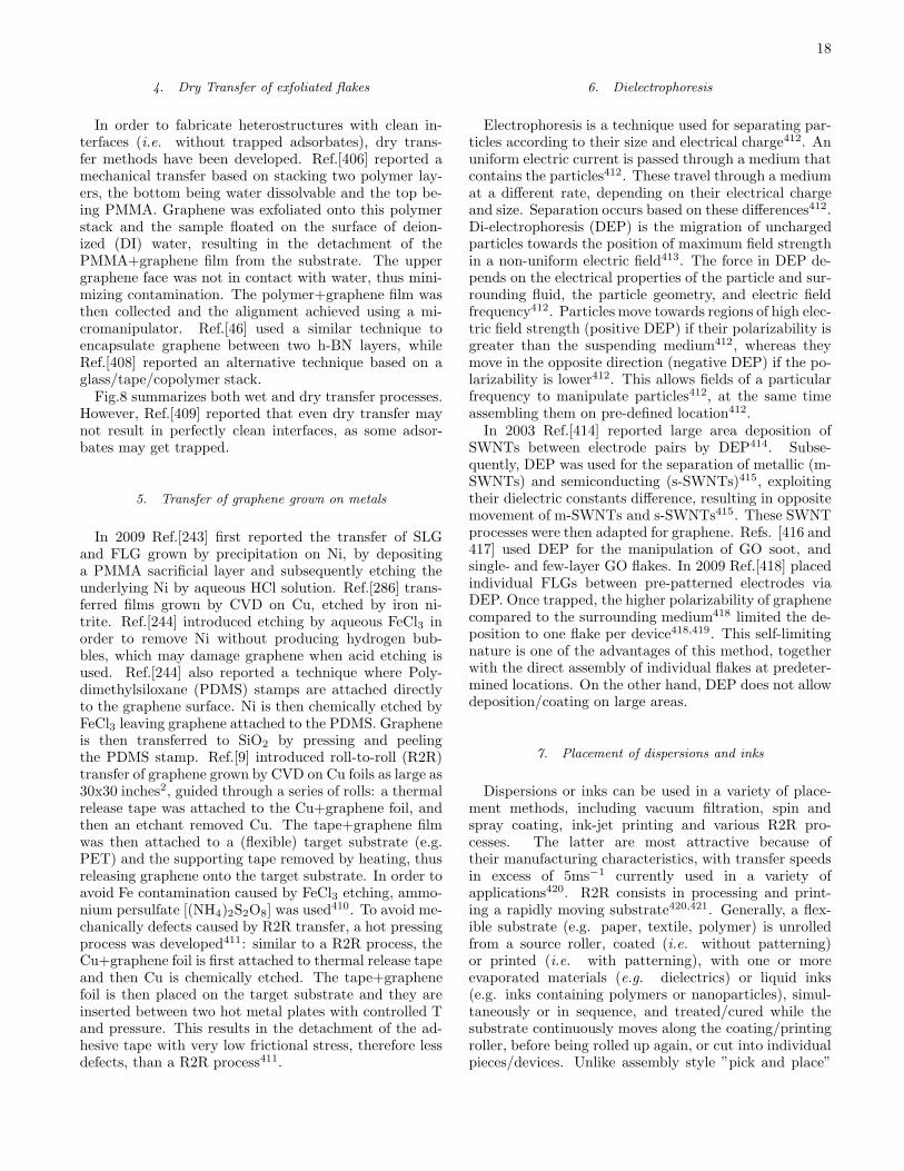
18
4. Dry Transfer of exfoliated flakes
In order to fabricate heterostructures with clean in-terfaces (i.e. without trapped adsorbates), dry trans-fer methods have been developed. Ref.[406] reported amechanical transfer based on stacking two polymer lay-ers, the bottom being water dissolvable and the top be-ing PMMA. Graphene was exfoliated onto this polymerstack and the sample floated on the surface of deion-ized (DI) water, resulting in the detachment of thePMMA+graphene film from the substrate. The uppergraphene face was not in contact with water, thus mini-mizing contamination. The polymer+graphene film wasthen collected and the alignment achieved using a mi-cromanipulator. Ref.[46] used a similar technique toencapsulate graphene between two h-BN layers, whileRef.[408] reported an alternative technique based on aglass/tape/copolymer stack.Fig.8 summarizes both wet and dry transfer processes.
However, Ref.[409] reported that even dry transfer maynot result in perfectly clean interfaces, as some adsor-bates may get trapped.
5. Transfer of graphene grown on metals
In 2009 Ref.[243] first reported the transfer of SLGand FLG grown by precipitation on Ni, by depositinga PMMA sacrificial layer and subsequently etching theunderlying Ni by aqueous HCl solution. Ref.[286] trans-ferred films grown by CVD on Cu, etched by iron ni-trite. Ref.[244] introduced etching by aqueous FeCl3 inorder to remove Ni without producing hydrogen bub-bles, which may damage graphene when acid etching isused. Ref.[244] also reported a technique where Poly-dimethylsiloxane (PDMS) stamps are attached directlyto the graphene surface. Ni is then chemically etched byFeCl3 leaving graphene attached to the PDMS. Grapheneis then transferred to SiO2 by pressing and peelingthe PDMS stamp. Ref.[9] introduced roll-to-roll (R2R)transfer of graphene grown by CVD on Cu foils as large as30x30 inches2, guided through a series of rolls: a thermalrelease tape was attached to the Cu+graphene foil, andthen an etchant removed Cu. The tape+graphene filmwas then attached to a (flexible) target substrate (e.g.PET) and the supporting tape removed by heating, thusreleasing graphene onto the target substrate. In order toavoid Fe contamination caused by FeCl3 etching, ammo-nium persulfate [(NH4)2S2O8] was used
410. To avoid me-chanically defects caused by R2R transfer, a hot pressingprocess was developed411: similar to a R2R process, theCu+graphene foil is first attached to thermal release tapeand then Cu is chemically etched. The tape+graphenefoil is then placed on the target substrate and they areinserted between two hot metal plates with controlled Tand pressure. This results in the detachment of the ad-hesive tape with very low frictional stress, therefore lessdefects, than a R2R process411.
6. Dielectrophoresis
Electrophoresis is a technique used for separating par-ticles according to their size and electrical charge412. Anuniform electric current is passed through a medium thatcontains the particles412. These travel through a mediumat a different rate, depending on their electrical chargeand size. Separation occurs based on these differences412.Di-electrophoresis (DEP) is the migration of unchargedparticles towards the position of maximum field strengthin a non-uniform electric field413. The force in DEP de-pends on the electrical properties of the particle and sur-rounding fluid, the particle geometry, and electric fieldfrequency412. Particles move towards regions of high elec-tric field strength (positive DEP) if their polarizability isgreater than the suspending medium412, whereas theymove in the opposite direction (negative DEP) if the po-larizability is lower412. This allows fields of a particularfrequency to manipulate particles412, at the same timeassembling them on pre-defined location412.In 2003 Ref.[414] reported large area deposition of
SWNTs between electrode pairs by DEP414. Subse-quently, DEP was used for the separation of metallic (m-SWNTs) and semiconducting (s-SWNTs)415, exploitingtheir dielectric constants difference, resulting in oppositemovement of m-SWNTs and s-SWNTs415. These SWNTprocesses were then adapted for graphene. Refs. [416 and417] used DEP for the manipulation of GO soot, andsingle- and few-layer GO flakes. In 2009 Ref.[418] placedindividual FLGs between pre-patterned electrodes viaDEP. Once trapped, the higher polarizability of graphenecompared to the surrounding medium418 limited the de-position to one flake per device418,419. This self-limitingnature is one of the advantages of this method, togetherwith the direct assembly of individual flakes at predeter-mined locations. On the other hand, DEP does not allowdeposition/coating on large areas.
7. Placement of dispersions and inks
Dispersions or inks can be used in a variety of place-ment methods, including vacuum filtration, spin andspray coating, ink-jet printing and various R2R pro-cesses. The latter are most attractive because oftheir manufacturing characteristics, with transfer speedsin excess of 5ms−1 currently used in a variety ofapplications420. R2R consists in processing and print-ing a rapidly moving substrate420,421. Generally, a flex-ible substrate (e.g. paper, textile, polymer) is unrolledfrom a source roller, coated (i.e. without patterning)or printed (i.e. with patterning), with one or moreevaporated materials (e.g. dielectrics) or liquid inks(e.g. inks containing polymers or nanoparticles), simul-taneously or in sequence, and treated/cured while thesubstrate continuously moves along the coating/printingroller, before being rolled up again, or cut into individualpieces/devices. Unlike assembly style ”pick and place”
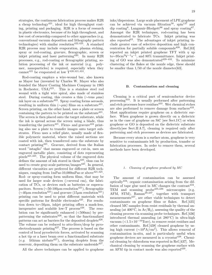
19
strategies, the continuous fabrication process makes R2Ra cheap technology421, ideal for high throughput coat-ing, printing and packaging. R2R is a focus of researchin plastic electronics, because of its high throughout, andlow cost of ownership compared to other approaches (e.g.conventional vacuum deposition and lithography patterntechnologies) with similar resolution422,423. A standardR2R process may include evaporation, plasma etching,spray or rod-coating, gravure, flexographic, screen orinkjet printing and laser patterning420. In many R2Rprocesses, e.g., rod-coating or flexographic printing, so-lution processing of the ink or material (e.g. poly-mer, nanoparticles) is required, especially when theycannot421 be evaporated at low T420,421,424.
Rod-coating employs a wire-wound bar, also knownas Mayer bar (invented by Charles W. Mayer who alsofounded the Mayer Coating Machines Company in 1905in Rochester, USA)421. This is a stainless steel rodwound with a tight wire spiral, also made of stainlesssteel. During coating, this creates a thin (∼tens µms)ink layer on a substrate422. Spray coating forms aerosols,resulting in uniform thin (∼µm) films on a substrate421.Screen printing, on the other hand, uses a plate or screencontaining the pattern to be printed on the substrate421.The screen is then placed onto the target substrate, whilethe ink is spread across the screen using a blade, thustransferring the pattern421. Flexo- and gravure424 print-ing also use a plate to transfer images onto target sub-strates. Flexo uses a relief plate, usually made of flex-ible polymeric material, where the raised sections arecoated with ink, then transferred onto the substrate bycontact printing421. Gravure, derived from the Italianword ”intaglio” that means engraved or cut-in, uses anengraved metallic plate, consisting of dots representingpixels421,425. The physical volume of the engraved dotsdefines the amount of ink stored in them425, thus can beused to create gray-scale patterns/images425. In general,different viscosities are preferred for different R2R tech-niques, ranging from 1mPas-10,000mPas or above421,425.Rod- or spray-coating form uniform films, that may beused for larger scale devices (>several cm), the fabri-cation of TCs, or devices such as batteries or superca-pacitors. Screen (∼50-100µm resolution421), flexographic(∼40µm resolution421) and gravure (15µm resolution421)printing can be used to print different materials withspecific patterns for flexible electronics425. For resolu-tion down to∼50µm, inkjet printing offers a mask-less,inexpensive and scalable low-T process426. The reso-lution can be significantly enhanced (<500nm) by pre-patterning the substrates426, so that the functionalizedpatterns can act as barriers for the deposited droplets426.The volume can be reduced to atto-liters/drop by pyro-electrodynamic printing427. The process is based on thecontrol of local pyroelectric forces, activated by scanninga hot tip or a laser beam over a functionalized substrate(e.g. lithium niobate427), drawing droplets from thereservoir, depositing them on the substrate underside427.
All the above techniques can be applied to graphene
inks/dispersions. Large scale placement of LPE graphenecan be achieved via vacuum filtration58, spin137 anddip coating6, Langmuir-Blodgett96 and spray coating67.Amongst the R2R techniques, rod-coating has beendemonstrated to fabricate TCs. Inkjet printing wasalso reported63. The advantages of inkjet printing in-clude greater ease of selective deposition and high con-centration for partially soluble compounds428. Ref.[63]reported an inkjet printed graphene TFT with η upto∼95cm2V−1s−1, and 80% transmittance. Inkjet print-ing of GO was also demonstrated429–432. To minimizeclustering of the flakes at the nozzle edge, these shouldbe smaller than 1/50 of the nozzle diameter[63].
B. Contamination and cleaning
Cleaning is a critical part of semiconductor deviceprocessing433. It is usually performed after patterningand etch processes leave residues433. Wet chemical etchesare also performed to remove damage from surfaces433.Most applications require graphene on a dielectric sur-face. When graphene is grown directly on a dielectricas in the case of graphene on SiC [see Sect.I C] or whengraphene or GO is deposited on the dielectric substratedirectly[see Sect.II A 7], cleaning is required only afterpatterning and etch processes as devices are fabricated.
Because every atom is a surface atom, graphene is verysensitive to contaminants left by production, transfer orfabrication processes. In order to remove them, severalmethods have been developed.
1. Cleaning of graphene produced by MC
The amount of contamination can be assessedoptically434: organic contamination arising from the dif-fusion of tape glue used in MC changes the contrast434.TEM and scanning probe435,436 microscopies (e.g.AFM, STM), Raman29,437, together with transportmeasurements437, are other viable techniques to detectcontaminants on graphene films or flakes. Ref.[435]cleaned MC samples from resist residuals by thermal an-nealing (at 400C, in Ar/H2), assessing the quality of thecleaning process via scanning probe techniques. Ref.[436]introduced thermal annealing (at 280C) in ultra-highvacuum (<1.5×10⁻¹⁰Torr), to remove resist residues andother contaminants. Ref.[438] cleaned graphene by us-ing high current (∼108A/cm2). This allows removal ofcontamination in-situ, and is particularly useful whengraphene devices are measured in a cryostat438. Chemi-cal cleaning by chloroform was reported in Ref.[437]. Me-chanical cleaning by scanning the graphene surface withan AFM tip in contact mode was also reported439.

20
2. Cleaning after transfer
Cleaning is particularly important when transferringflakes, as the processes typically involves sacrificial lay-ers, to be chemically dissolved, see Sect.II A 4. Thermalannealing in H2/Ar is normally used46,409,440.In graphene transfer from metals to dielectric surfaces,
organic materials such as PMMA or Perylene-3,4,9,10-tetracarboxylic dianhydride (PTCDA) are typically usedas the carrier material, with subsequent chemical re-moval, e.g. by acetone229,286. Great care must be takento ensure that PMMA or PTCDA are completely re-moved. Refs.[441 and 442] detected by XPS (X-ray pho-toelectron spectroscopy) the presence of residue on thesurface of graphene grown on Cu and transferred ontoSiO2. The C1s spectrum was found broader than that ofgraphite and the original graphene on Cu. The broaden-ing was associated with the presence of the residue. Uponannealing in high vacuum (1×10⁻⁹ mbar) at T∼300C,the C1s width decreased to a value close to the orig-inal graphene on Cu441,442. The use of thermal releasetape9 (i.e. a tape adhesive at RT, but that peels off whenheated), instead of PMMA or PTCDA, is more problem-atic, since tape residues can contaminate the transferredgraphene9. There is some anecdotal evidence that thepresence of residue has a beneficial effect on the nucle-ation of ALD dielectrics, such as Al2O3
443. However,this approach to prepare the graphene surface for ALDis not ideal, since the residues have uncontrolled chem-ical nature and are not uniform. Ref.[444] developed amodified RCA transfer method, combining an effectivemetal cleaning process with control of the hydrophilicityof the target substrates. RCA stands for Radio Corpora-tion of America, the company that first developed a setof wafer cleaning steps in the semiconductor industry433.Ref.[444] demonstrated that RCA offers a better controlboth on contamination and crack formation with respectto the aforementioned approaches9,229,286.
3. Removal of solvents/surfactants in LPE graphene
For graphene and GO produced via LPE, the cleaning,removal of solvents and/or surfactants, mainly dependson the target applications. For composites (both formechanical134 and photonic14,15,62 applications) the pres-ence of surfactants does not compromise the mechanicaland optical properties, thus their removal is not needed,and is in fact essential to avoid agglomeration14,15,62,134.Different is the situation when the applications requirehigh conductivity (>104Scm−1), i.e. TCFs. In thiscase, the presence of solvents/surfactants compromisesthe interflake connections, decreasing the electrical per-formance. The solvents and the deposition strategy (seeSect.II A 7) used for the TCFs production mostly de-termines the cleaning procedure. In the case of TCFsproduced by vacuum filtration (i.e. on a cellulose fil-ter membrane) of surfactant-assisted aqueous disper-
sions, the as-deposited graphene or RGO films are firstrinsed with water to wash out the surfactants59,65 andthen transferred from the membrane to the target sub-strate. The membrane is then usually dissolved in ace-tone and methanol445. For freestanding films, the de-posited flakes are peeled off from the membrane59. Thefilms are then annealed at T>250C in Ar/N2
59 or air65.The latter process could help remove residual surfactantmolecules59,65. However, there is not a ”fixed” T forthe removal of the solvents/surfactants, and the differ-ent conditions/requirements are essentially ruled by theboiling/melting points of each solvent/surfactant.
III. INORGANIC LAYERED COMPOUNDSAND HYBRID STRUCTURES
A. 2d crystals
There are several layered materials, whose bulk prop-erties were studied already in the sixties446, which retaintheir stability down to monolayers, and whose propertiesare complementary to those of graphene.Transition metal oxides (TMOs) and transition metal
dichalcogenides (TMDs) have a layered structure446.Atoms within each layer are held together by covalentbonds, while van der Waals interactions hold the lay-ers together446. LMs include a large number of systemswith interesting properties446. E.g., NiTe2 and VSe2are semi-metals446, WS2, WSe2, MoS2, MoSe2, MoTe2,TaS2, RhTe2, PdTe2 are semiconductors446, h-BN, andHfS2 are insulators, NbS2, NbSe2, NbTe2, and TaSe2 aresuperconductors446; Bi2Se3, Bi2Te3 show thermoelectricproperties446 and may be topological insulators447.Due to the weak bonding of the stacked layers446,
LMs were mainly used as solid lubricants becauseof their tribological properties448. In addition, LMswere also used as thermoelectric materials449, inbatteries450, electrochemical451 and photovoltaics (PV)cells452, light emitting diodes453, as ion exchangers454,photocatalysts455, etc.Similar to graphite and graphene, the LM properties
are a function of N. E.g., bulk MoS2 has an indirect bandgap456, while a monolayer has a direct band gap457,458,that could be exploited for optoelectronics459.We now highlight the most promising routes for pro-
duction of 2d crystals and hybrids.
1. Micromechanical cleavage
As with graphene, individual layers can be made byMC25. MC can involve a single crystal22, or a singlegrain22, in the case of polycrystalline materials460. Thelocal scale dynamics of the fracture process is complex22
and depends on the crystal structure22. To date the lat-eral size of 2d crystals produced via MC is∼10µm in h-BN461, limited by the average crystal size of the start-

21
ing material461. Similar size flakes (∼10µm) were alsoachieved via MC of MoS2, WS2 and NbSe2
462.
As in the case of MC of graphite, MC of LMs is notindustrially scalable, and MC-flakes are mostly suited forfundamental studies and proof of concept devices.
2. Laser ablation
Ref.[463] used laser pulses to ablate TMDs (MoS2)down to a single-layer. Ref.[463] generated single layer-MoS2 [1L-MoS2] in arbitrary shapes and patterns withfeature sizes down to 200nm, with electronic and opti-cal properties comparable to MC-1L-MoS2
462. Indeed,Ref.[463] reported similar PL emission between MC-1L-MoS2 and laser thinned 1L-MoS2, and η up to 0.49cm2
V−1 s−1 and 0.85cm2 V−1 s−1 for laser thinned and MC-1L-MoS2, respectively.
3. Liquid Phase Exfoliation
LPE can exfoliate LMs in organic solvents464–469 andaqueous solutions470,471, with470, or without471 surfac-tants, or their mixtures472. The exfoliated sheets canthen be stabilized against re-aggregation either by inter-action with solvent464, or through electrostatic repulsiondue to the adsorption of surfactant molecules87,470. Inthe case of solvent stabilization, Ref.[464] showed thatthe best solvents are those having surface tension match-ing the surface energy of the target LM. The dispersionscan then produce inks with a variety of properties63, orbe used for processing in thin films and/or composites464.
Research is still at an early stage, and LPE must beextended to a wider range of materials. To date, exfoli-ated TMDs both in organic solvents464 and surfactant-aqueous solutions470 tend to exist as multilayers464,470.Yields can be defined for LPE of LMs in the same wayas done for graphene, see Sect.I B. Ref.[473] reportedYW=40% for MoS2 dispersions. To the best of ourknowledge, thus far no data exist for YM and YWM inLPE TMOs and TMDs. In order to determine YW alibrary of α for all LMs must be produced. To date,α values were suggested only for few LMs, i.e. MoS2(3400mLmg−1 m−1), WS2 (2756mLmg−1 m−1) and BN(2367mLmg−1 m−1)464. However, as in the case ofgraphene, there is uncertainly in the determination of α.E.g., Ref.[464] reported α ∼3400mLmg−1 m−1 for MoS2,while Ref.[473] used 1020mL mg−1 m−1.
As in the case of graphene, the development of a sort-ing strategy in centrifugal fields, both in lateral dimen-sions and N, will be essential.
Refs.[453, 474–477] used intercalation of alkali metalswith TMD crystals (i.e. MoS2 and WS2) to increase theinter-layer distance and facilitate exfoliation.
4. Synthesis by thin film techniques
A number of thin film processes can be brought tobear on the growth of 2d crystals. These range fromPVD (e.g. sputtering), evaporation, vapor phase epi-taxy, liquid phase epitaxy, chemical vapor epitaxy, MBE,ALE, and many more, including plasma assisted pro-cesses. The selection of the growth process dependson the material properties needed and the application.Each material has its own challenges and we do not aimhere to describe each one individually. However, we notethat, other than controlling the thickness and orienta-tion of the films, their composition and stoichiometry isof utmost importance, having large influence on trans-port. As a result, great care must be taken in controllingthe point defect concentration. Low growth T (∼300C)techniques are usually better suited in controlling the de-fects arising from vacancies, since the vapor pressure ofthe chalcogenide elements decreases exponentially withT478. However, low T techniques tend to give higherextended defect densities because of the lower atomicmobility479. Therefore, the growth technique must beselected to match the application very carefully.To date, WS2 films have been deposited by magnetron
sputtering from both WS480 and WS2 targets481, sulfu-rization of W482 or WO2 films483, ion beam mixing484,etc. The preferred production process for tribologicalapplications is magnetron sputtering485, because of itslower T than thermally activated deposition methods485.Magnetron sputtering is also well suited for large areadeposition (∼m2)486. CVD was used to grow h-BN487,and is now being developed to grow TMDs488. If singlelayers of the binary films are desired, then ALD or, moreappropriately, ALE might be better suited.
5. 2d crystals nanoribbons
Nanoribbons based on 2d crystals can also be made,with tuneable electrical and magnetic properties489,490.MoS2 nanoribbons were produced via electrochemi-cal/chemical synthesis489, while zigzag few- and single-layer BN nanoribbons were produced via unzipping mul-tiwall BN nanotubes through plasma etching490.
B. Graphene and other 2d crystals hybrids
Technological progress is determined, to a great ex-tent, by developments in material science. The mostsurprising breakthroughs are attained when a new typeof material, or new combinations of known materials,with different dimensionality and functionality, are cre-ated. Well-known examples are the transition from three-dimensional (3d) semiconducting structures based on Geand Si to 2d semiconducting heterostructures, nowadaysthe leading platform for microelectronics. Ultimately, thelimits and boundaries of certain applications are given by

22
FIG. 10. Schematic hybrid superstructure(SLG/BN/MoS2/BN/SLG).
the very properties of the materials naturally available tous. Thus, the band-gap of Si dictates the voltages used incomputers, and the Young’s modulus of steel determinesthe size of the construction beams. Heterostructuresbased on 2d crystals will decouple the performance of par-ticular devices from the properties of naturally availablematerials. 2d crystals have a number of exciting proper-ties, often unique and very different from those of theirthree-dimensional (3d) counterparts. However, it is thecombinations of such 2d crystals in 3d stacks that offertruly unlimited opportunities in designing the functional-ities of such heterostructures. One can combine conduc-tive, insulating, probably superconducting and magnetic2d materials in one stack with atomic precision, fine-tuning the performance of the resulting material. Fur-thermore, the functionality of such stacks is ”embedded”in the design of such heterostructures.Heterostructures have already played a crucial role
in technology, giving us semiconductor lasers and high-mobility field effect transistors (FET). However, thus farthe choice of materials has been limited to those whichcan be grown (typically by MBE) one on top of another,thus limiting the types of structures which can be pre-pared. Instead, 2d crystals of very different nature canbe combined in one stack with atomic precision, offeringunprecedented control on the properties and functional-ities of the resulting 2d-based heterostructures. 2d ma-terials with very different properties can be combinedin one 3d structure, producing novel, multi-functionalmaterials. Most importantly, the functionality of suchheterostructures will not simply be given by the com-bined properties of the individual layers. Interactionsand transport between the layers allow one to go be-yond simple incremental improvements in performanceand create a truly ”quantum leap” in functionality. Bycarefully choosing and arranging the individual compo-
nents one can tune the parameters, creating materialswith tailored properties, or ”materials on demand”. Fol-lowing this novel approach, part of the functionality isbrought to the level of the design of the material itself.Inorganic LMs can be exploited for the realization
of heterostructures with graphene, to modulate/changethe electronic properties, thus creating ”materials ondemand”: hybrid superstructures, with properties notexisting in nature46,491–493, tailored for novel appli-cations. E.g., superstructures like those in Fig.10(SLG/BN/MoS2/BN/SLG) can be used for tunnel de-vices, such as diodes, FETs, and light emitting devices,or for energy application, such as PV cells.To date, 3 methods can be envisaged for the pro-
duction of atomically thin heterostructures: (I) growthby CVD305; (II) layer by layer stacking via mechanicaltransfer46,406,494 and (III) layer by layer deposition ofchemically exfoliated 2d crystals. However, as the fielddevelops, other techniques will emerge.Field effect vertical tunnelling transistors based on
graphene heterostructures with atomically thin BN act-ing as a tunnel barrier, were reported493. The deviceoperation relies on the voltage tunability of the tunneldensity of states in graphene and of the effective height ofthe tunnel barrier adjacent to the graphene electrode493.Ref.[495] used Ws2 as an atomically thin barrier, allowingswitching between tunneling and thermionic transport,with much better transistor characteristics with respectto the MoS2 analogue493, thus allowing much higherON/OFF ratios (∼106). A ”barristor”, a graphene-silicon hybrid three-terminal device that mimics a triodeoperation, was developed by Ref.[496]. The electrostat-ically gated graphene/silicon interface induce a tunableSchottky barrier that controls charge transport across avertically stacked structure493,496.
1. CVD growth of heterostructures
CVD is suitable for mass production ofheterostructures497,498, though it requires the largestinvestment and effort in terms of identifying theprecursors, CVD system design and process develop-ment. There are several indications that it is indeedfeasible497,498. h-BN was shown to be effective as asubstrate for CVD as well as exfoliated graphene499.
2. Mechanical transfer
Transfer individual 2d crystals into heterostructuresenabled the observation of several interesting effects,including FQHE406, ballistic transport46 and metal-insulator transition in graphene491. An advantage of”dry” mechanical transfer is the possibility to con-trol/modify each layer as it is being deposited, includingchemical modifications, at any stage of the transfer pro-cedure. Also, any atomic layer in the multilayer stack can

23
be individually contacted, offering precise control on theproperties of the stack (in principle giving a material withindividual contacts to every atomic plane). Furthermore,one can apply local strains to individual layers. Thesecan significantly modify their electronic structure500–502.Also important is the control of the layer relative orienta-tion, which may affect electronic properties of the stackin certain intervals of the energy spectrum503.
3. Heterostructures from dispersions and inks
Large-scale placement of LPE samples for the produc-tion of heterostructures can be achieved exploiting thetechniques reported in Sect.II A 7, tuning the propertiesof the dispersion/ink accordingly. E.g., surface modifica-tions by self-assembled monolayers enable targeted large-scale deposition. High uniformity and well defined struc-tures on flexible substrates can also be obtained. DEPcan be used to control the placement of individual crys-tals between pre-patterned electrodes. Inkjet printing al-lows to mix and print layers of different materials and isa quick and effective way of mass-production. Solvother-mal synthesis, i.e. synthesis in a autoclave using non-aqueous precursors504, of MoS2 deposited on RGO sheetssuspended in dispersion was recently reported505.
IV. OUTLOOK AND FUTURE CHALLENGES
The successful introduction of graphene and/or other2d materials in products depends not only on the identifi-cation of the right products for new and current applica-tions, but also on the ability to produce any of the mate-rials in large quantities at a reasonable cost. The progressin developing new materials processes over the past fewyears has been impressive, especially given the broadmaterials requirements, from single crystal graphene tographene flakes. The suitability of any given process de-pends on the application. Nanoelectronics more thanlikely has the most demanding requirements, i.e. low de-fect density single crystals. Other applications, such asbiosensors, may require defective graphene, while print-able electronics can tolerate lower quality, e.g. lower mo-bility, graphene. Chemical vapour deposition techniquesare emerging as ideal processes for large area graphenefilms for touch screens and other large display applica-tions, while graphene derived from SiC single crystals
may be better suited for resistor standards. Many issuesstill remain to be addressed in the growth of grapheneby CVD to improve the electrical and optical charac-teristics, including mechanical distortions, stable doping,and the development of reliable low cost transfer tech-niques. While transfer techniques can be developed totransfer graphene layers onto insulating substrates, it isdesirables to grow graphene directly on dielectric sur-faces for many device applications and progress is beingmade in achieving films on hexagonal boron nitride aswell as SiO2. However, a lot more effort is required toachieve large area uniform high quality graphene films ondielectrics. In the case of graphene on SiC, among otherissues related to uniformity, crystal size could be a ma-jor cost impediment for large scale production. Liquidphase exfoliation is appealing for the production of inks,thin films and composites, and future research is neededto control on-demand the number of layers, flake thick-ness and lateral size, as well as rheological properties.Synthetic graphenes are the most promising for the pro-duction of atomically precise nanoribbons and quantumdots to overcome the lack of band gap necessary for manydevice applications. A controlled dopant distribution isalso needed, and techniques such as surgace functional-ization using self-assembled acceptor/donor molecules orassembling pre-doped molecules are being studied.The layered nature of graphite makes its integration
with other layered materials a natural way to create het-erostructures. Layered materials have been around fora long time and studied and developed mostly for theirtribological properties. Now they are being considered asnew interlayer dielectrics for heterostructures that havepotential for new electronic devices with exotic proper-ties. Because of their potential for new devices, therewill be a host of new processes that will need to be de-veloped in order to grow or deposit high quality largearea monolayer films integrated with graphene with con-trolled thickness and transport properties.
V. ACKNOWLEDGMENTS
We acknowledge M. Bruna, A. Colli, R. Sundaram,R. Weatherup, K. S. Novoselov, for useful discus-sions and funding from ERC NANOPOTS, EPSRCEP/GO30480/1 and EP/F00897X/1, EU RODIN andGENIUS, the Newton Trust, the Royal Academy of En-gineering, King’s College, Cambride, the NRI programand a Royal Society Wolfson Research Merit Award.
∗ [email protected] Geim, A. K., Novoselov, K. S., Nature Mater (2007) 6,183.
2 Zhang, Y., et al., Nature (2005) 438, 201.3 Du, X., et al., Nature (2009) 462, 192.4 Charlier, J. C., et al., Top Appl Phys (2008) 111, 673.
5 Bonaccorso, F., et al., Nature Photon (2010) 4, 611.6 Wang, X., et al., Nano Lett (2007) 8, 323.7 Wu, J., et al., ACS Nano (2009) 4, 43.8 Mayer, J., et al., Solid State Comm (2007) 143, 101.9 Bae, S., et al., Nature Nanotech (2010) 4, 574.
10 Xia, F., et al., Nature Nanotech (2009) 4, 839.
24
11 Mueller, T., et al., Nature Photon (2010) 4, 297.12 Echtermeyer, T. et al., Nature Comm (2011) 2, 458.13 Konstantatos, G., et al., Nature Nanotech (2012) 7, 363.14 Sun, Z., et al., ACS Nano (2010) 4, 803.15 Hasan, T., et al., Adv Mater (2009) 21, 3874.16 Booth, T., et al., Nano Lett (2008) 8, 2442.17 Chung, K., et al., Science (2010) 330, 655.18 Hill, E. W., et al., IEEE Trans Magn (2006) 42, 2694.19 Tombros, N., et al., Nature (2007) 448, 571.20 Lin, Y. M., et al., Science (2010) 327, 662.21 Kinaret, J., et al., Proc Comp Sci (2011) 7, 30.22 Schultz, R. A., et al., Int Jour Fracture (1994) 65, 291.23 Romero, R., et al., Clay Miner (1992) 27, 31.24 Lu, X., et al., Nanotechnology, (1999) 10, 269.25 Novoselov, K. S., et al., PNAS (2005) 102, 10451.26 Geim, A. K., Science (2009) 324, 1530.27 Casiraghi, C. et al., Nano Lett (2007) 7, 2711.28 Ferrari, A. C., et al., Phys Rev Lett (2006) 97, 187401.29 Casiraghi, C., et al., Appl Phys Lett (2007) 91, 233108.30 Pisana, S., et al., Nature Mater (2007) 6, 198.31 Das, A., et al., Nature Nanotech (2008) 3, 210.32 Ferrari, A. C., Robertson, J., Phys Rev B (2000) 61,
14095.33 Ferrari, A. C., et al., Phys Rev B (2001) 64, 075414.34 Ferrari, A. C., Robertson, J., Phil Trans Roy Soc A (2004)
362, 2477.35 Cancado, L. G., et al., Nano Lett (2011) 11, 3190.36 Ferralis, N., et al., Phys Rev Lett (2008) 101, 156801.37 Mohiuddin, M. G., et al., Phys Rev B (2009) 79, 205433.38 Ferrari, A. C., Solid State Comm (2007) 143, 47.39 Elias, D. C., et al., Science, (2009) 323, 610.40 Casiraghi, C., et al., Nano Lett (2009) 9, 1433.41 Basko, D. M., et al., Phys Rev B (2009) 80, 165413.42 Neugebauer P., et al., Phys Rev Lett 103, 136403.43 Elias, D. C., et al. Nature Phys (2011) 7, 701.44 Ni, Z. H., et al., Nano Lett (2010) 10, 3868.45 Mayorov, A. S., et al., Nano Lett (2012) 12, 4629.46 Mayorov, A. S., et al., Nano Lett (2011) 11, 2396.47 Albaugh, K. B., J Electrochem Soc (1991) 138, 3089.48 Henmi, H., et al., Sens Act A (1994) 43, 243.49 Shukla, A., et al. Solid State Commun (2009) 149, 718.50 Moldt, T., et al., ACS Nano (2011) 5, 7700.51 Chrisey, D. B., Hubler, G. K., Pulsed Laser Deposition of
Thin Films, by Douglas B. Chrisey, Graham K. Hubler(Editor), pp. 648 Wiley-VCH, May 2003.
52 Miyamoto, Y., et al., Phys Rev Lett (2010) 104, 208302.53 Dhar, S., et al., AIP Adv (2011) 1, 022109.54 Reininghaus, M., et al., Appl Phys Lett (2012) 100,
151606.55 Lee, S. W., et al., ACS Nano (2010) 4, 7524.56 Qian, M., et al., Appl Phys Lett (2011) 98, 173108.57 Mortazavi, S. Z., et al., Laser Phys Lett (2012) 9, 547.58 Hernandez, Y., et al., Nature Nanotech (2008) 3, 563.59 Lotya, M., et al., J Am Chem Soc (2009) 131, 3611.60 Lotya, M., et al., ACS nano (2010) 4, 3155.61 Khan, U., et al., Small (2010) 6, 864.62 Hasan, T., et al., Phys Status Solidi B (2010) 247, 2953.63 Torrisi, F., et al., ACS Nano, (2012) 6, 2992.64 Valles, C., et al., J Am Chem Soc (2008) 130, 15802.65 Green, A. A., Hersam, M. C., Nano Lett (2009) 9, 4031.66 Marago, O. M. et al., ACS Nano (2010) 4, 7515.67 Blake, P. et al., Nano Lett (2008) 8, 1704.68 Mason, T. J., Sonochemistry; Oxford (1999).
69 Israelachvili, J., Intermolecular and surface force. Boston:Academic Press third edition (2011).
70 Ghatee, M. H., Pakdel, L., Fluid Phase Equil (2005)234,101.
71 Lyklema, J., J Colloids Surf A (1999) 156, 413.72 Wang, S., et al., Langmuir (2009) 25, 11078.73 Shin, Y. J., et al., Langmuir (2010) 26, 3798.74 Solomon, H. M., et al., Drug Chem Toxicol (1995) 18,
271.75 Kennedy, G. L., Sherman, H., Drug Chem Toxicol (1986)
9, 147.76 O’Neill, A., et al., J Phys Chem C (2011) 115, 5422.77 Seo, J-W. T., et al., J Phys Chem Lett (2011) 2, 1004.78 Nirmalraj, P. N., et al., Nano Lett (2011) 11, 1663.79 Svedberg, T., Pedersen, K. O., The Ultracentrifuge, Ox-
ford (1940).80 Behrens, M., Z. Hoppe-Seyler’s Pphysiol. Chem. 258, 27
(1939).81 Alzari, V., et al., J Mater Chem (2011) 21, 8727.82 Lide, D. R., In Handbook of Chemistry and physics 86th
ed.; CRC Press Inc.; Boca Raton, FL, (2005).83 Williams, J. W., et al., Chem Rev (1958) 58, 715.84 Arnold, M. S., et al., Nano Lett (2005) 5, 713.85 Crochet, J. J., et al., J Am Chem Soc (2007) 129, 8058.86 Arnold, M. S., et al., Nature Nanotech (2006) 1, 60.87 Bonaccorso, F., et al., J Phys Chem C (2010) 114, 17267.88 Sun, X., et al., ACS Nano (2010) 4, 3381.89 Tyler, T. P., et al., J Phys Chem Lett (2011) 2, 218.90 Akbulut, O., et al., Nano Lett (2012) 12, 4060.91 Nuvoli, D., et al., J Mater Chem (2011) 21, 3428.92 Wang, X., et al., Chem Commun (2010) 46, 4487.93 Welton, T., Chem Rev (1999) 99, 2071.94 Shang, N. G., et al., Chem Commun (2012) 48, 1877.95 An, X., et al., Nano Lett (2010) 10, 4295.96 Li, D. et al., Nature Nanotech (2008) 3, 101.97 Li, X., et al., Science (2008) 319, 1229.98 Zheng, W., Wong, S C., Comp Sci Tech (2003) 63, 225.99 Forsman, W. C., et al., Carbon (1978) 16, 269.
100 McAllister, M. J., et al., Chem Mater (2007) 19, 4396.101 Brodie, B. C., Ann Chim Phys (1860) 59, 466.102 Staudenmaier, L. V., Ber Deut Chem Ges (1898) 31,
1481.103 Dreyer, D. R., et al., Chem Soc Rev (2010) 39, 1.104 Hyde, F. S., J Soc Chem Ind (1904) 23, 300.105 Kohlschtter, V., Haenni, P. Z., Anorg Allg Chem (1918)
105, 121.106 Ruess, G., Vogt, F., Monatsh fur Chemie (1948) 78, 222.107 Hummers, W. S., Offeman, R. E., J Am Chem Soc (1958)
80, 1339.108 Mattevi, C., et al., Adv Funct Mater (2009) 19, 2577.109 Cai, W., et al., Science (2008) 321, 1815.110 Boehm, H. P., Proc. of the Fifth Conference on Carbon,
Pergamon Press, London p. 73 (1962).111 Stankovich, S., et al., Carbon (2007) 45, 1558.112 Lomeda, J. R., et al., J Am Chem Soc (2008) 130, 16201.113 H. C. Schniepp, et al., J. Phys. Chem. B 11, 8535 (2006).114 Niyogi, S. et al., J Am Chem Soc (2006) 128, 7720.115 Paredes, J. I., et al., Langmuir (2008) 24, 10560.116 Si, Y., Samulski, E. T., Nano Lett (2008) 8, 1679.117 Su, C.-Y., et al., Chem Mater (2009) 21, 5674.118 Becerril, H. A., et al., ACS Nano (2008) 2, 463.119 Gokus, T. et al., ACS Nano (2009) 3, 3963.120 Sun, X., et al., Nano Res (2008) 1, 203.121 Eda, G., et al., Adv Mater (2009) 21, 505.
25
122 Matyba, P., et al., ACS Nano (2011), 5, 574.123 Boehm, H. P., et al., Z. Naturforschung (1962) 17b, 150.124 Gomez-Navarro, C., et al., Nano Lett (2007) 7, 3499.125 Bourlinos, A. B., et al., Langmuir (2003) 19, 6050.126 Chen, Y., et al., Chem Commun (2009) 4527.127 Liao, K-H., et al., ACS Nano (2011) 5, 1253.128 Wang, H. J., et al., J Am Chem Soc (2009) 131, 9910.129 Williams, G. et al., ACS Nano (2008) 2, 1487.130 Kaiser, A. B., et al., Nano Lett (2009) 9, 1787.131 Lopez, V., et al., Adv Mater (2009) 21, 1.132 Su, Q. et al., Adv Mater (2009) 21, 1.133 Brown, A. R., et al., Synth Met (1997) 88, 37.134 Stankovich, S. et al., Nature (2006) 442, 282.135 Korkus, S. et al., ACS Nano, (2011) 5, 5214.136 Lin, Y.-M., et al., Nano Lett (2008) 9, 422.137 Eda, G. et al., Nature Nanotech (2008) 3, 270.138 Mativetsky, J. M., et al., J Am Chem Soc (2010) 132,
14130.139 Wang, X., et al., Angew Chem (2008) 47, 2990.140 Bao, Q., et al., Adv Funct Mat (2010) 20, 782.141 Sun, Z. et al., Proc. CLEO, (2011) JWA79.142 Dresselhaus, M. S., Dresselhaus, G. Adv Phys (2002) 51,
1.143 Inagaki, M. J Mater Res (1989) 4, 1560.144 Boehm, H-P., et al., Pure Appl Chem (1994) 66, 1893.145 Schaffautl, P., J Prakt Chemie (1841) 21, 155.146 Hoffman, U., Feanzel, A., Z Elektrochem (1931) 37, 613.147 Vogel, F. L. et al., Mat Sci Eng (1977) 31, 261.148 Foley, G. M. T., et al., Solid State Comm (1977) 24, 371.149 Shioya, J., et al., Synth Met (1986) 14, 113.150 Spain, I. L., Chemistry and Physics of Carbon, Vol. 8
edited by P. L. Walker (New York; Marcel Dekker) p.105(1973).
151 Hannay, N. B., et al., Phys Rev Lett (1965) 14, 225.152 Weller, T. E., et al., Nature Phys (2005) 1, 39.153 Csanyi, G., et al., Phys Rev B (2007) 75, 085432.154 Deng, W-Q., et al., Phys Rev Lett (2004) 92, 166103.155 Enoki, T., et al., Graphite Intercalation Compounds and
Applications. Oxford University press (2003).156 Watanabe, N., Fukuda, M., US Patent 3536532, (1970).157 Besenhard, J. O., Carbon (1976) 14, 111.158 Nobuatsu, W., Solid State Ionics (1980) 1, 87.159 Winter, M., et al., Adv Mater (1998) 10, 725.160 Yazami, R., Electrochim Acta (1999) 45, 87.161 Yazami, R., Touzain, P., J. Power Sources (1983) 9, 365.162 Hrold, A., Bull Soc Chim Fr (1955) 187, 999.163 Ebert, L. B., Annu Rev Mater Sci (1976) 6, 181.164 Croft, R. C., Q Rev Chem Soc (1960) 14, 1.165 Zhao, W., et al., J Am Chem Soc (2011) 133, 5941.166 Falardeau, E. R., et al., Inorg Chem (1978) 17, 301.167 Kwon, J., et al., Small (2011) 7, 864.168 Lerf, A., et al., J Phys Chem B (1998) 102, 4477.169 Ang, P. K., et al., ACS Nano (2009) 3, 3587.170 Catheline, A., et al., Chem Comm (2011) 47, 5470.171 Vogel, F. L., J Mater Sci (1977) 12, 982.172 Khrapach, I., et al., Adv Mater (2012) 24, 2844.173 Acheson, E. G., U.S. Patent 615648, (1896).174 Badami, D. V., Nature (1962) 193, 570 (1962).175 Van Bommel, A., et al., Surf Sci (1975) 48, 463.176 Forbeaux, I., et al., Appl Surf Sci (2000) 162, 406.177 Charrier, A., et al., J Appl Phys (2002) 92, 2479.178 Berger, C., et al., J Phys Chem B (2004) 108, 19912.179 Emtsev, K. V., et al., Nature Mater (2009) 8, 203.180 Emtsev, K. V., et al., Phys Rev B (2008) 77, 155303.
181 Varchon, F., et al., Phys Rev Lett (2007) 99, 126805.182 Hass, J., et al., Phys Rev Lett (2008) 100, 125504.183 Riedl, C., et al., Phys Rev Lett (2009) 103, 246804.184 Goler, S., et al., Carbon (2013) 51 249.185 http://mrsec.gatech.edu/epitaxial− graphene186 Royer, L., Bull Soc Fran Min (1928) 51, 7.187 Bachmann, K. J., et al., J Vac Sci Technol A (1995) 13,
696.188 Schneider, H. G., Acta Cryst (1963) 16, 1261.189 Pashley, D. W., Adv Phys (1965) 14, 327.190 Pashley, D. W., Proc phys Soc Lond A (1956) 65, 33.191 Jain, S. C., et al., J Appl Phys (1996) 79, 8145.192 Ago, H., et al., Acs Nano (2010) 4, 7407.193 Ueno, T. et al., Appl. Surf. Sci (1997) 113 33.194 Koma, A., J Cryst Growth (1999) 201 236.195 Jaegermann, W., et al., Thin Solid Films (2000) 380, 276.196 De Heer, W., et al., PNAS (2011) 108, 16900.197 De Heer, W., arXiv:1012.1644v1.198 Hass, J., et al., Appl Phys Lett (2006) 89, 143106.199 Hass, J., et al., Phys Rev B (2008) 78, 205424.200 Tromp, R., Hannon, J., Phys Rev Lett (2009) 102,
106104.201 Fonda, G. R., Phys Rev (1923) 21, 343.202 Sorkin, V., Zhang, Y. W., Phys Rev B (2010) 81, 085435.203 Sprinkle, M., et al., Nature Nanotech (2010) 5, 727.204 Dawlaty, J. M., et al., Appl Phys Lett (2008) 92, 042116.205 Tedesco, J. L., et al., Appl Phys Lett (2009) 95, 122102.206 Davis, R. F., et al., Proc. IEEE (1991) 79, 677.207 Kedzierski, J., et al., IEEE Trans. Electron Devices (2008)
55, 2078.208 Li, X., et al., Science (2010) 327, 662.209 Schwierz, F., Nature Nanotech (2010) 5, 487.210 Novoselov, K., et al., Nature (2005) 438, 197.211 www.tankeblue.com/news−55−en.html212 www.i-micronews.com/upload/Rapports/
Yole−Sapphire−Market−November−2011−Flyer.pdf213 McArdle, T. J., et al., Appl Phys Lett (2011) 98, 132108.214 Russo, V., et al., Towards graphene epitaxy on Si.
Graphene Week 2009 Universitatszentrum ObergurglAustria 2-7 March 2009.
215 Matsunami, H., et al., J Cryst Growth (1978) 45, 138.216 Boo, J.-H., et al., Appl Phys Lett (1995) 66, 19.217 Nishino, S., et al., J Electrochemical Soc (1980) 127, 2674.218 Ikoma, K., et al., J Electrochemical Soc (1991) 138, 3028.219 Ouerghi, A., et al., Appl Phys Lett (2010) 96, 191910.220 Ouerghi, A. et al., Phys. Rev. B (2010) 82, 125445.221 Coletti, C., et al., Appl Phys Lett (2011) 99, 081904.222 Lipson, H., Stokes, A. R., Proc R Soc Lond A (1942) 181,
101.223 Biscoe, J., Warren, B. E., J Appl Phys (1942) 13, 364.224 Shelton, J. C., et al., Surf Sci (1974) 43, 493.225 Winder, S. M., et al., Carbon (2006) 44, 3037.226 Walker, P. L., Imperial, G., Nature (1957) 180, 1184.227 Derbyshire, F. J., et al., Carbon (1975) 13, 111.228 Massalski, Th. B., et al., in: Massalski, Th. B., Okamoto,
H., Subramanian, P. R., Kacprzak, L., (Eds.), Binary Al-loy Phase Diagrams, ASM International, (1990).
229 Li, X., et al., Science (2009) 324, 1312.230 Okamoto, H., C-Hf (Carbon-Hafnium), Binary Alloy
Phase Diagrams, II Ed., Ed. Massalski, T.B., Vol. 1, p.849-852 (1990).
231 Cadoff, I., Nielsen J. F., Trans Am Inst Min Metall PetEng (1953) 197, 248.
232 Fernandez Guillermet, A., J Alloys Comp (1995) 217, 69.

26
233 Okamoto, H., Phase Diagrams for Binary Alloys, DeskHandbook, Vol. 1, (2000).
234 Kaufman, L., Calphad (1979) 3, 45.235 Ruan, G. D., et al., Acs Nano (2011) 5, 7601.236 Sun, Z. Z., et al., Nature (2010) 468, 549.237 Guermoune, A., et al., Carbon (2011) 49, 4204.238 Miyasaka, Y., et al., Jpn J Appl Phys (2011) 50, 04DH12.239 Miyata, Y., et al., Appl Phys Lett (2010) 96, 263105.240 Karu, A. E., Beer, M., J Appl Phys (1966) 37, 2179.241 Peters, K. R., J Microsc Oxford (1984) 133, 17.242 Powell, C. F., et al., Vapour Deposition edited by Powell,
C. F., Joseph, H. O., John, M. B., Blocher, M., New YorkWiley, (1966).
243 Reina, A., et al., Nano Lett (2009) 9, 30.244 Kim, K. S., et al., Nature (2009) 457, 706.245 Reina, A., et al., Nano Res (2009) 2, 509.246 Yu, Q., et al., Appl Phys Lett (2008) 93, 113103.247 Ramon, M. E., et al., Acs Nano (2011) 5, 7198.248 N’Diaye, A. T., et al., Phys Rev Lett (2006) 97, 215501.249 Hamilton, J. C., Blakely, J. M., Surf Sci (1980) 91, 199.250 Himpsel, F. J., Surf Sci (1982) 115 L159.251 Yoshii, S., et al., Nano Lett (2011) 11, 2628.252 Pan, Y., et al.,Chin Phys(2007) 16, 3151.253 Pan, Y., et al.,Adv Mater(2009) 21, 2777.254 Little, R. B., J Cluster Sci (2003) 14, 135.255 Sutter, P. W., et al., Nature Mater (2008) 7, 406.256 Sutter, P., et al., Phys Rev B, (2009) 80, 245411.257 Loginova, E. et al., New J Phys, (2008) 10, 093026.258 McCarty, K. F., et al., Carbon (2009) 47, 1806.259 Loginova, E., et al., Phys Rev B (2009) 80 085430.260 Vazquez de Parga, A. L., et al., Phys Rev Lett (2008) 100,
056807.261 Coraux, J., et al., Nano Lett (2008) 8, 565.262 Vaari, J., et al., Catal Lett (1997) 44, 43.263 Land, T. A., et al., Surf Sci (1992) 264, 261.264 Busse, C., et al., Phys Rev Lett, (2011) 107, 036101.265 Jiang, D-E., et al., J Chem Phys (2009) 130, 074705.266 Zhang, H., et al., J Phys Chem C (2009) 113, 8296.267 Dai, B. F., et al., Nature Comm (2011) 2, 522.268 Sutter, P. W., et al., Appl Phys Lett (2010) 97, 213101.269 Peng, Z. W., et al., Acs Nano (2011) 5, 8241.270 Kern, W., Schnable, G. L., IEEE Trans Electron Devices
(1979) 26, 647.271 Xu, Y., Yan, X.-T., Chemical Vapour Deposition: An
Integrated Engineering Design for Advanced MaterialsSpringer, (2009).
272 Meyyappan, M., et al., Plasma Sources Sci. Technol. 12,205 (2003).
273 Perdereau, J., Rhead, G. E., Surf Science (1971) 24, 551.274 Kholin, N. A., Surf Sci (1984) 139, 155.275 Gall, N. R., et al., Carbon (2000) 38, 663.276 Charrier, C., Diamond Relat Mater (1994) 3, 41.277 Moller, K., Holmlid, L., Appl. Surf. Sci (1987) 29, 474.278 Orofeo, C., et al., Nano Research (2011) 4, 531.279 Gambino, J. P., Colgan, E. G., Mater Chem Phys, (1998)
52, 99.280 Maex, K., Mater Sci Eng R (1993) 11, 53.281 Morimoto, T., et al., IEEE Trans Electron Devices, (1995)
textbf42, 915.282 Lavoie, C., et al., Microelectron Eng (2003) 70, 144.283 Zhang, S. L., Ostling, M., Crit Rev Solid State Mater Sci
(2003) 28, 1.284 Li, X., et al., Nano Lett (2009) 9, 4268.285 Lopez, G. A., Mittemeijer, E., Scr Mat (2004) 51, 1.
286 Li, X., et al., Nano Lett (2009) 9, 4359.287 Petrone, N., et al., Nano Lett (2012) 12, 2751.288 Li, X., et al., Nano Lett (2010) 10, 4328.289 Li, X., et al., J Am Chem Soc (2011) 133, 2816.290 Frese, K. L., Surf Sci (1987) 182, 85.291 Aoyama, T., et al., Jpn J Appl Phys Part 1 (1999) 38,
2194.292 Yoon, D., et al., Nano Lett (2011) 11, 3227.293 Addou, R., et al., Appl Phys Lett (2012) 100, 021601.294 Vertman, A. A., et al., Dokl Akad Nauk SSSR (1965) 162,
1304.295 Li, Z., et al., ACS Nano (2011) 5, 3385.296 Kehrer, V. J., Leidheiser, H., J Phys Chem (1954) 58,
550.297 Lee, S., et al., Nano Lett (2010) 10, 4702.298 Liu, N., et al., Nano Lett (2011) 11, 297.299 Sun, J. et al., Appl Phys Lett (2011) 98, 252107.300 Scott, A. et al., Appl Phys Lett (2011) 98, 073110.301 Rummeli, M. H., et al., ACS Nano (2010) 4 4206.302 Strupinski, W., et al., Nano Lett (2011) 11, 1786.303 Fanton, M. A., et al., Acs Nano (2011) 5, 8062.304 Herron, C. R., et al., J Mater Chem (2011), 21, 3378.305 Tanaka, T. et al., Surf Rev Lett (2003) 10 721.306 Song, L., et al., Nano Lett (2010) 10, 3209.307 Shi, M. et al., Nano Lett (2010) 10, 4134.308 Liu, Z., et al., Nano Lett (2011) 11, 2032.309 Chhowalla, M., et al., J Appl Phys (2001) 90, 5308.310 Teo, K. B. K., et al., Nanotechnology (2001) 14, 204.311 Hofmann, S. et al., Phys Rev Lett (2005) 95 036101.312 Boskovic, B. O., et al., Nature Mater (2002) 1, 165.313 Casiraghi, C. et al., Mater Today (2007) 10, 44.314 Casiraghi, C. et al., Phys Rev Lett (2003) 91, 226104.315 Moseler, M., et al., Science (2005) 309, 1545.316 Kim, J. et al., Appl Phys Lett (2011) 98, 091502.317 Terasawa, T.-o., Saiki, K., Carbon (2012) 50, 869.318 Lee, J. et al., RF Performance of Pre-patterned Locally-
embedded-Back-Gate Graphene Device. In 2010 Interna-tional Electron Devices Meeting - Technical Digest, IEEE,New York, (2010).
319 Burden, A. P., et al., Phyl Mag Lett (1998) 78, 15.320 Wang, J. et al., Carbon (2004) 42, 2867.321 Malesevic, A. et al., Nanotechnology (2008) 19 305604.322 French, B. L., et al., J Appl Phys (2005) 97, 114317.323 French, B. L., et al., Thin Solid Films (2006) 494 105.324 Chuang, A. T., et al., Appl Phys Lett (2007) 90, 123107.325 Chuang, A. T. H., et al., Diamond Relat Mater (2006)
15, 1103.326 Mori, S., et al., Diamond Relat Mater (2011) 20, 1129.327 Cho, A. Y., Arthur, J. R., Prog. Solid State Chem (1975)
10, 157.328 Al-Temimy, A., et al., Appl Phys Lett (2009) 95, 231907.329 Jerng, S. K., et al., J Phys Chem C (2011) 115, 4491.330 Liu, Z., et al., Solid State Commun (2012) 152, 960.331 Seifarth, O., et al., DOI: 10.1109/SCD.2011.6068742.332 Lippert, G., et al., Phys Stat Solidi B (2011) 248, 2619.333 Garcia, J. M., et al., Solid State Commun (2010) 150,
809.334 Hackley, J., et al., Appl Phys Lett (2009) 95, 133114.335 Garcia, J. M., et al., Solid State Commun (2012) 152,
975.336 Jerng, S. K., et al., J Phys Chem C (2012) 116, 7380.337 Tsang, W. T., Appl Phys Lett (1984) 45, 1234.338 Lee, K. Y., et al., Appl Phys Lett (2006) 89, 222906.339 Suntola, T., Mater Sci Rep (1989) 4 261.

27
340 Ritala, M., et al., Chem Mater (1999) 11, 1712.341 Ritala, M., et al., Chem Vap Dep (1999) 5, 7.342 Kim, H., et al., J Mater Res (2004) 19, 643.343 S.Aisemberg, R. Chabot, J.Appl. Phys 42, 2953 (1971)344 Ferrari, A. C., et al., J Appl Phys (1999) 85, 7191.345 Kleinsorge, B., et al., J Appl Phys (2000) 88, 1149.346 Ilie, A., et al., J Appl Phys (2001) 90, 2024.347 Ilie, A., et al., Appl Phys Lett (2000) 76, 2627.348 Conway, N. M. J., et al., Diamond Rel Mat (2000) 9 765.349 Barreiro, A., et al., arXiv:1201.3131v1.350 Westenfelder, B., et al., Nano Lett (2011) 11, 5123.351 Chhowalla, M., et al., Appl Phys Lett (2000) 76, 1419.352 Ferrari, A. C., et al., Phys Rev B (2000) 62, 1189.353 Turchanin, A., et al., ACS Nano (2011) 5, 3896.354 Wu, J., et al., Chem Rev (2007) 107, 718.355 Cai, J., et al., Nature (2010) 466, 470.356 Yan, X., et al., Nano Lett (2010) 10, 1869.357 Zhi, L., Mullen, K. A., J Mater Chem (2008) 18, 1472.358 Dossel, L., et al., Angewandte Chemie int Ed (2011) 50,
2540.359 Inoue, K., Prog Polym Sci (2000) 25, 453.360 Han, M. Y., et al., Phys Rev Lett (2007) 98, 206805.361 Z. Chen, et al., Physica E (2007) 40, 228.362 Ponomarenko, L. A., et al., Science (2008) 320, 356.363 Kosynkin, D. V., et al., Nature (2009) 458, 872.364 Sinitskii, A., Tour, J. M., IEEE Spectr (2010) 47, 28.365 Sinitskii, A., et al., Appl Phys Lett (2009) 95, 253108.366 Tapaszto, L., et al., Nature Nanotech (2008) 3, 397.367 Singh, A. K., et al., Nano Lett (2009) 9, 1540.368 Lee, W. K., et al., Nano Lett (2011) 11, 5461.369 Wei, Z., et al., Science (2010) 328, 1373.370 Ci, L., et al., Nano Res (2008) 1, 116.371 Campos, L. C., et al., Nano Lett (2009) 9, 2600.372 Lu, J., et al., ACS Nano (2009) 3, 2367.373 Spinkle, M., et al., Nature Nanotech (2010) 5, 727.374 Rehahn, M., et al., Polymer (1989) 30, 1054.375 Fasoli, A., et al., Phys Stat Sol B (2009) 246, 2514.376 Kulmala, T. S., et al., ACS Nano (2011) 5, 6910.377 Pan, Z., et al., J Am Chem Soc (2011) 133, 17578.378 Zhang, Z., et al., Phys Rev Lett (2009) 103, 187204.379 Son, Y. W., et al., Nature (2006) 444, 347.380 Cervantes-Sodi, F., et al., Phys Rev B (2008) 77, 165427.381 Pan, D., et al., Adv. Mater (2010), 22, 734.382 Zhu, S., et al., Chem. Comm, (2011), 47, 6858.383 Shen, J., et al., Chem. Comm (2011), 47, 2580.384 Li, Y., et al., Adv. Mater (2011), 23, 776.385 Lu, J., et al., Nature Nanotech (2011), 6, 247.386 Liu, R., et al., J. Am. Chem. Soc (2011), 133, 15221.387 Chen, C., et al., Nature Nanotech (2009) 4 861.388 Meyer, J. C., et al., Nature (2008) 454, 319.389 Schneider, G. F., et al., Nano Lett. (2010) 10, 3163.390 Nair, R. R., et al., Appl Phys Lett (2010) 97, 153102.391 Schneider, G. F., Dekker, C., Nature Biotech (2012) 30,
326.392 Well D. B., et al., Nano Lett (2012) 12, 4117.393 Albrecht, T., Nature Nanotech (2011) 6, 195.394 Meyer, J. C., et al., Science (2005) 309, 1539.395 Meyer, J. C., et al., Nature (2007) 446, 60.396 Bunch, J. S., et al., Science (2007) 315, 490.397 Meyer, J. C., et al., Appl Phys Lett (2008) 92, 123110.398 Nair, R., et al., Science (2008) 320, 1308.399 Du, X., et al., Nature Nanotech (2008) 3, 491.400 Bolotin, K. I., et al., Solid State Comm (2008) 146, 351.401 Bolotin, K. I., et al., Nature (2009) 462, 196.
402 M. A. Meitl, et al., Nano Lett. 4, 1643 (2004).403 Jiao, L., et al., J Am Chem Soc (2008) 130, 12612.404 Reina, A., et al., J Phys Chem C (2008) 112, 17741.405 Dekker, G. F., et al., Nano Lett (2010) 10, 1912.406 Dean, C. R., et al., Nature Nanotech (2010) 5, 722.407 Yasin, S., et al., Appl Phys Lett (2001) 78, 2760.408 Zomer, P. J., et al., Appl Phys Lett (2011) 99, 232104.409 Haigh, S. J., et al., Nature Mater (2012) 11, 764.410 Aleman, B., et al., ACS Nano (2010) 4, 4762.411 Kang, J., et al., ACS Nano (2012) 6, 5360.412 Johns, T. B., Electromechanisms of Particles, Cambridge
University Press, Cambridge (1995).413 Pohl, H. A., J Appl Phys (1951) 22, 869.414 Krupke, R., et al., Nano Lett (2003) 3, 1019.415 Krupke, R., et al., Science (2003) 301, 344.416 Burg, B. R., et al., Appl Phys Lett (2009) 94, 053110.417 Kang, H., et al., Carbon (2009) 47, 1520.418 Vijayaraghavan, A., et al., ACS Nano (2009) 3, 1729.419 Hong, S., et al., J Nanosci Nanotechnol (2008) 8, 424.420 Cheng, I-C., Wagner, S., Overview of Flexible Electronics
Technology. In Flexible Electronics: Materials and Ap-plications, Wong, W. S., and Salleo, A., (eds.) Springer,New York, pp 1 (2009).
421 Coatings Technology Handbook, Tracton, A. A., (ed.)CRC Press, Boca Raton, FL, (2006).
422 Sheats, J. R., Roll-to-roll manufacturing of thin film elec-tronics. In Emerging Lithographic Technologies VI Rox-ann, L. E., (ed.) SPIE, Santa Clara, CA, USA, Vol.4688,pp 240 (2002).
423 Choi, M-C., et al., Prog Polym Sci (2008) 33, 581.424 Wong, W. S., et al., Materials and Novel Patterning Meth-
ods for Flexible Electronics. In Flexible Electronics: Ma-terials and Applications, Wong, W. S., and Salleo, A.,(eds.) Springer, New York, (2009).
425 Solution Processing of Inorganic Materials, Mitzi, D. B.,(ed.) John Wiley and Sons, Inc., Hoboken, New Jersey,(2009).
426 Noh, Y. Y., et al., Nature Nanotech (2007) 2, 784.427 Ferraro, P., et al., Nature Nanotech (2010) 5, 429.428 Calvert, P., Chem Mater (2001) 13, 3299.429 Jo, Y. M., et al., Chem Lett (2011) 40, 54.430 Luechinger, N. A., et al Nanotechnology (2008) 19,
445201.431 Wang, S., et al., Nano Lett (2010) 10, 92.432 Yu, Y., et al., Appl Phys Expr (2011) 4, 115101.433 Handbook of Semiconductor Wafer Cleaning Technol-
ogy:Science, Technology, and Applications, Edited byKern, W., Noyes Publication New Jersey (1993).
434 Bruna, M., et al., J Phys D: Appl Phys (2009) 42, 175307.435 Ishigami, M., et al., Nano Lett (2007) 7, 1643.436 Stolyarova, E., et al., PNAS (2007) 104, 9209.437 Cheng, Z., et al., Nano Lett (2011) 11, 767.438 Moser, J., et al., Appl Phys Lett (2007) 91, 163513.439 Goossens, A. M., et al., Appl Phys Lett (2012) 100,
073110.440 J. Yan, M. S. Fuhrer, Phys. Rev. Lett 107, 206601 (2011).441 Pirkle, A., et al., Appl Phys Lett (2011) 99, 122108.442 Chan, J., et al., ACS Nano, (2012) 6, 3224.443 Lee, B., et al., ECS Trans (2009) 19, 225.444 Liang, X., et al., ACS Nano (2011) 5, 9144.445 Wu, Z. C., et al., Science (2004) 305, 1273.446 Wilson, J. A., Yoffe, A. D., Adv Phys (1969) 18, 193.447 Kane, C. L., Mele, E. J., Phys Rev Lett (2005) 95, 226801.448 Prasad, S. V., Zabinski, J. S., Nature (1997) 387, 761.

28
449 Mishra, S. K., et al., J Phys Condens Matter (1997) 9,461.
450 Poizot, P., et al., Nature (2000) 407, 496.451 Abruna, H. D., Bard, A. J., J Electrochem Soc (1982)
129, 673.452 Djemail, G., et al., Sol Energy Mat (1981) 5, 403.453 Frey, G. L., et al., J Am Chem Soc (2003) 125, 5998.454 Clement, R. P., Inorg Chem (1978) 17, 2754.455 Kudo, A., J Am Chem Soc (1999) 121, 11459.456 Gmelin Handbook of Inorganic and Organometallic
Chemistry, 8th ed.; Springer-Verlag: Berlin, Vol. B7(1995).
457 Splendiani, A., et al., Nano Lett (2010) 10, 1271.458 Mak, K. F., et al., Phys Rev Lett (2010) 105, 136805.459 Sundaram, R., et al., arXiv:1211.4311 (2012).460 Suryanarayana, C., Int Mater Rev (1995) 40, 41.461 Pacile, D., et al., Appl Phys Lett (2008) 92, 133107.462 Benameur, M. M., et al., Nanotechnology (2011) 22,
125706.463 Castellanos-Gomez, A., et al., Nano Lett (2012) 12, 3187.464 Coleman, J. N., et al., Science (2011) 331, 568.465 Han, W. Q., et al., Appl Phys Lett (2008) 93, 22.466 Lin, Y., et al., J Phys Chem Lett (2010) 1, 277.467 Warner, J. H., et al., ACS Nano (2010) 4, 1299.468 Zhi, C. Y., et al., Adv Mater (2009) 21, 2889.469 Cunningham, G., et al., ACS Nano (2012) 6, 3468.470 Smith, R. J., et al., Adv Mater (2011) 23, 3944.471 Lin, Y., et al., J Phys Chem C (2011) 115, 2679.472 Zhou, K. G., et al., Angewandte Chemie Int Ed (2011)
50, 10839.473 O’Neill, A., et al., Chem Mater (2012) 24, 2414.474 Liu, C., et al., Thin Solid Films (1984) 113, 165.475 Joensen, P., et al., Mater Res Bull (1986) 21, 457.
476 Zahurak, S. M., Murphy, D. W., J Solid State Chem(1987) 70, 137.
477 Eda, G., et al., Nano Lett (2011) 11, 5111.478 Li, C., et al., ACS Nano (2012) 6, 8868.479 Kizilyalli, M., et al., Pure Appl Chem (1999) 71, 1307.480 Buck, V., Thin Solid Films (1991) 198, 157.481 Rai, A. K., et al., Surf Coat Technol (1997) 92, 120.482 Matthus, A., et al., J Electrochem Soc (1996) 144, 1013.483 Genut, M., et al., Thin Solid Films (1992) 217, 91.484 Hirano, M., Miyake, S., Appl Phys Lett (1985) 47, 683.485 Ellmer, K., in: Low Temperature Plasmas. Fundamen-
tals, Technologies and Techniques, Vol. 2, edited by Hip-pler, R., Kersten, H., Schmidt, M., and Schoenbah, K. H.,(Wiley-VCH, Berlin, 2008), p. 675.
486 Szczyrbowski, J., et al., Thin Solid Films (1999) 351, 254.487 Nagashima, A., et al., Phys Rev B (1995) 51, 4606.488 Zhang, Y., et al., Small (2012) 8, 966.489 Li, Q., et al., Nano Lett (2004) 4, 277.490 Zheng, H., et al., Nano Lett (2010) 10, 5049.491 Ponomarenko, L. A., et al., Nature Phys (2011) 7, 958.492 Ramasubramaniam, A., et al., Nano Lett (2011) 11, 1070.493 Britnell, L., et al., Science (2012) 335, 947.494 Ponomarenko, L. A., et al., Phys Rev Lett (2009) 102,
206603.495 Georgiou, T., et al., arXiv:1211.5090 (2012).496 Yang, H., et al., Science (2012) 336, 1140.497 Liu, Z., et al., Nano Lett (2011) 11, 2032.498 Shi, Y., et al., Nano Lett (2012) 12, 2784.499 Kim, E., et al., Appl Phys Lett (2011) 98, 262103.500 Pereira, V. M., Castro Neto, A. H., Phys Rev Lett (2009)
103, 046801.501 Mucha-Kruczynski, M., Phys Rev B, (2011) 84, 041404.502 Mayorov, A., et al., Science (2011) 333, 860.503 Luican, A., et al., Phys Rev Lett (2011) 106, 126802.504 Chen, X. M., Tong, M. L., Acc Chem Res (2007) 40, 162.505 Li, Y., et al., J Am Chem Soc (2011) 133, 7296.