Production of any Bevel Gear on 5-Axis...
26
Slide 1 02.04.2014 Dipl. Ing. Jürg Langhart KISSsoft AG Rosengartenstrasse 4 8608 Bubikon Schweiz Tel: +41 55 254 20 50 Fax: +41 55 254 20 51 [email protected] www.KISSsoft.AG WISSEN TEILEN Production of any Bevel Gear on 5-Axis Machine
Transcript of Production of any Bevel Gear on 5-Axis...

Slide 1
02.04.2014
Dipl. Ing. Jürg Langhart
KISSsoft AG
Rosengartenstrasse 4
8608 Bubikon
Schweiz
Tel: +41 55 254 20 50
Fax: +41 55 254 20 51
www.KISSsoft.AG
WISSEN TEILEN
Production of any
Bevel Gear on
5-Axis Machine

Slide 2
02.04.2014
Dipl. Ing. Jürg Langhart www.KISSsoft.AG
Content
1. Introduction
2. Demands on bevel gear models
3. Topological modification
4. Calculation and results
5. Measuring and rolling
6. Conclusion and outlook
Slide 3
02.04.2014
Dipl. Ing. Jürg Langhart www.KISSsoft.AG
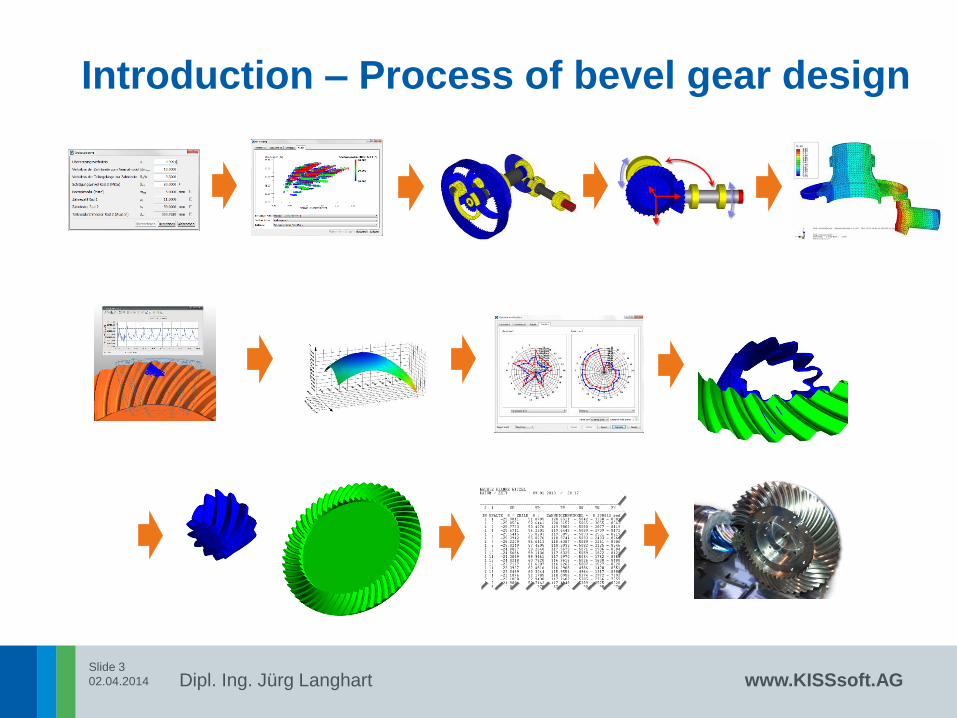
Introduction – Process of bevel gear design

Slide 4
02.04.2014
Dipl. Ing. Jürg Langhart www.KISSsoft.AG
Introduction – bevel gear production
production with 5-Axis machine conventional Production
productivity
flexibility
based on
3D models
based on bevel gear
machine settings

Slide 5
02.04.2014
Dipl. Ing. Jürg Langhart www.KISSsoft.AG
Introduction – actual situation
There is a need for 5-Axis milled bevel gears because:
• The existing conventional machines “are getting older”
• For small batches the machine equipment and production line is
unreasonable expensive
• High flexibility for usage of 5-Axis machines in the production (can be
used for other tasks as well)

Slide 6
02.04.2014
Dipl. Ing. Jürg Langhart www.KISSsoft.AG
Introduction – process of 5 Axis milling
STEP
Modell Production CAM
Slide 7
02.04.2014
Dipl. Ing. Jürg Langhart www.KISSsoft.AG
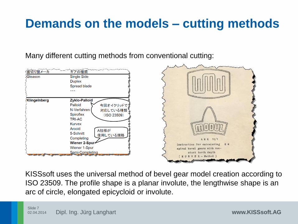
Demands on the models – cutting methods
Many different cutting methods from conventional cutting:
KISSsoft uses the universal method of bevel gear model creation according to
ISO 23509. The profile shape is a planar involute, the lengthwise shape is an
arc of circle, elongated epicycloid or involute.
Slide 8
02.04.2014
Dipl. Ing. Jürg Langhart www.KISSsoft.AG
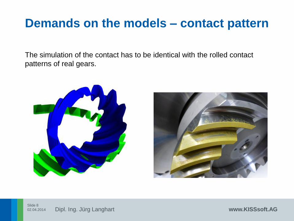
Demands on the models – contact pattern
The simulation of the contact has to be identical with the rolled contact
patterns of real gears.
Slide 9
02.04.2014
Dipl. Ing. Jürg Langhart www.KISSsoft.AG
Demands on the models – modifications
In the conventional production, each cutting method allows different
modifications, which are
• Lengthwise crowning by cutter head tilt, different blade radii, …
• Profile crowning by blade, hollow cone, …
• Modified roll, 1. to n-order
• Helical motion, 1. to n-order
• UMCTM with Ease off optimization per segment
• …
The modification types and their combination is almost infinitive
Slide 10
02.04.2014
Dipl. Ing. Jürg Langhart www.KISSsoft.AG
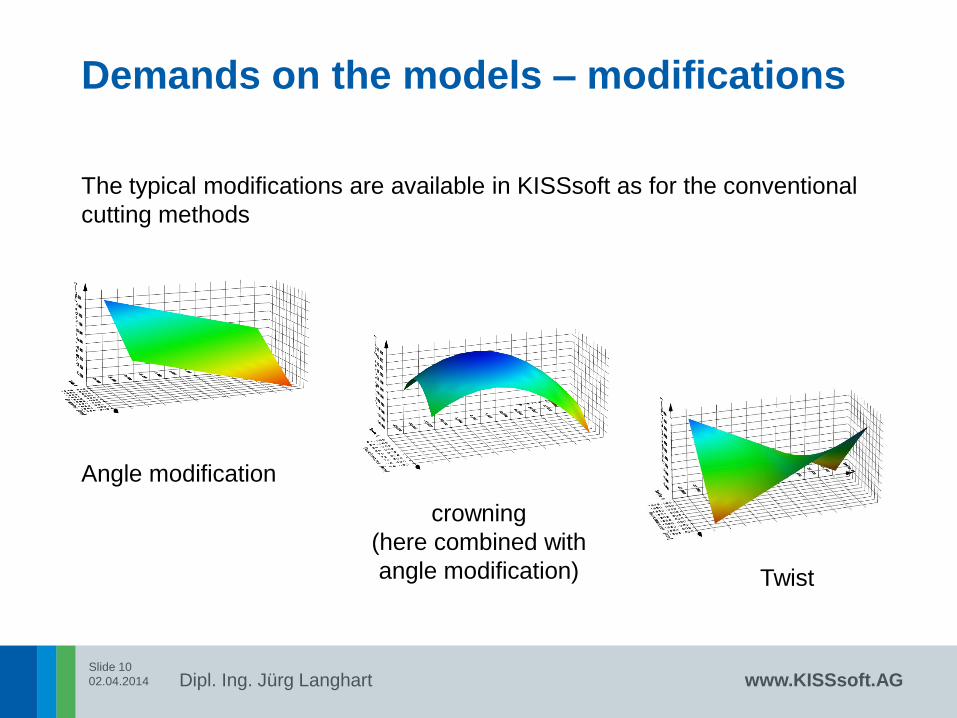
Demands on the models – modifications
The typical modifications are available in KISSsoft as for the conventional
cutting methods
Angle modification
crowning
(here combined with
angle modification) Twist
Slide 11
02.04.2014
Dipl. Ing. Jürg Langhart www.KISSsoft.AG
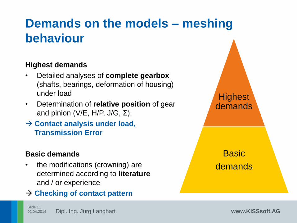
Highest demands
• Detailed analyses of complete gearbox
(shafts, bearings, deformation of housing)
under load
• Determination of relative position of gear
and pinion (V/E, H/P, J/G, Σ).
Contact analysis under load,
Transmission Error
Basic demands
• the modifications (crowning) are
determined according to literature
and / or experience
Checking of contact pattern
Demands on the models – meshing
behaviour
Highest demands
Basic
demands
Slide 12
02.04.2014
Dipl. Ing. Jürg Langhart www.KISSsoft.AG
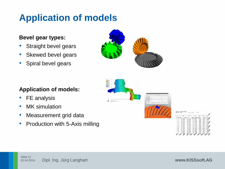
Application of models
Bevel gear types:
• Straight bevel gears
• Skewed bevel gears
• Spiral bevel gears
Application of models:
• FE analysis
• MK simulation
• Measurement grid data
• Production with 5-Axis milling
Slide 13
02.04.2014
Dipl. Ing. Jürg Langhart www.KISSsoft.AG
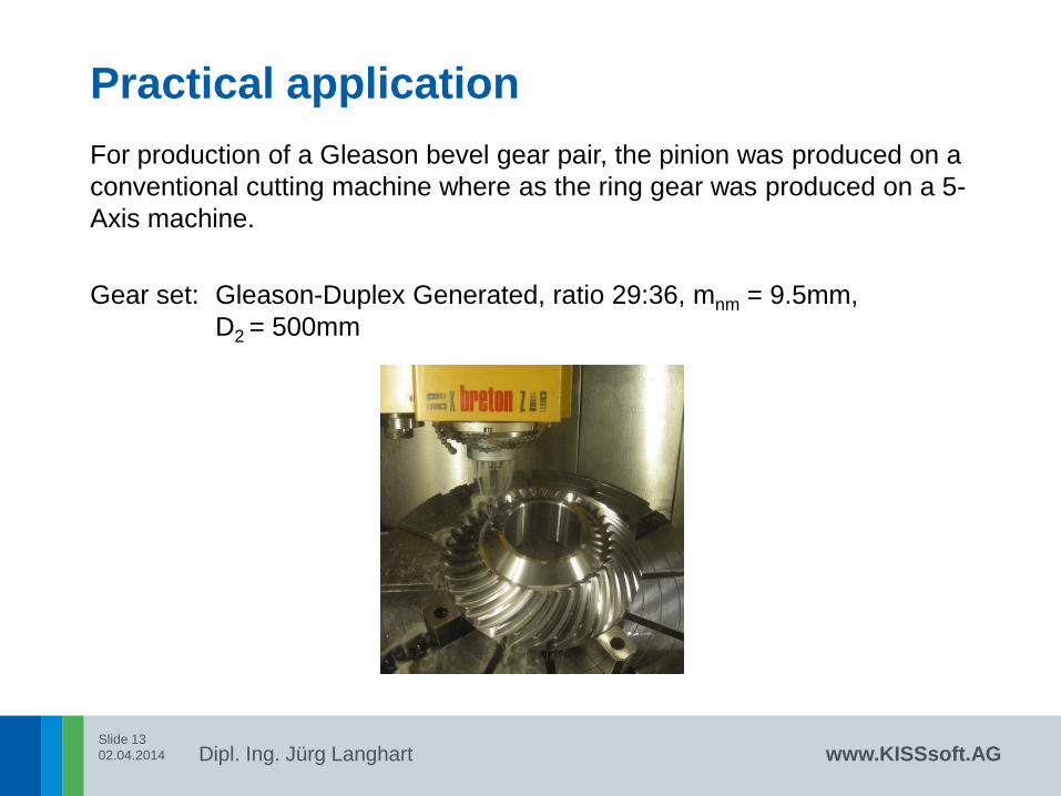
Practical application
For production of a Gleason bevel gear pair, the pinion was produced on a
conventional cutting machine where as the ring gear was produced on a 5-
Axis machine.
Gear set: Gleason-Duplex Generated, ratio 29:36, mnm = 9.5mm,
D2 = 500mm
Slide 14
02.04.2014
Dipl. Ing. Jürg Langhart www.KISSsoft.AG
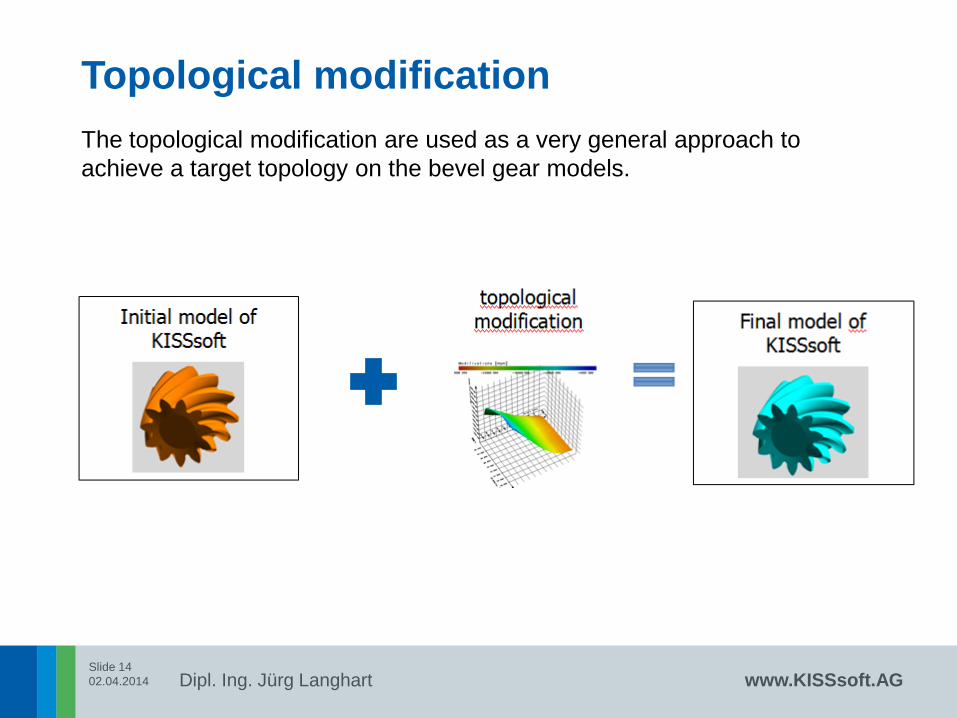
Topological modification
The topological modification are used as a very general approach to
achieve a target topology on the bevel gear models.
Slide 15
02.04.2014
Dipl. Ing. Jürg Langhart www.KISSsoft.AG
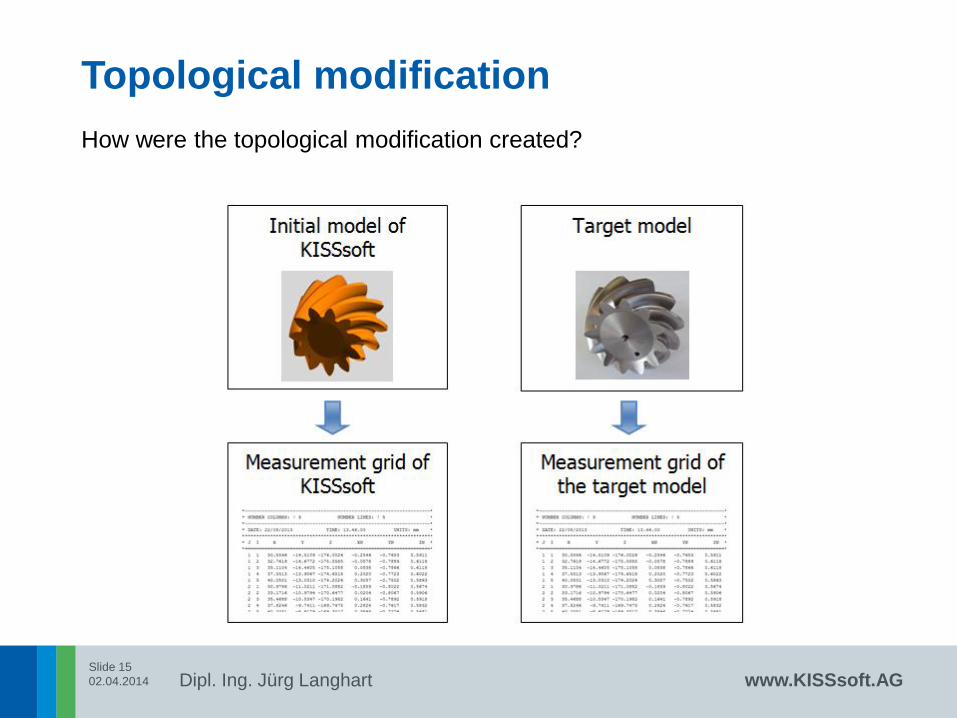
Topological modification
How were the topological modification created?

Slide 16
02.04.2014
Dipl. Ing. Jürg Langhart www.KISSsoft.AG
Topological modification
The difference between the measurements grid data is used.

Slide 17
02.04.2014
Dipl. Ing. Jürg Langhart www.KISSsoft.AG
Topological modification
The topological modification is added to the KISSsoft model.
Slide 18
02.04.2014
Dipl. Ing. Jürg Langhart www.KISSsoft.AG
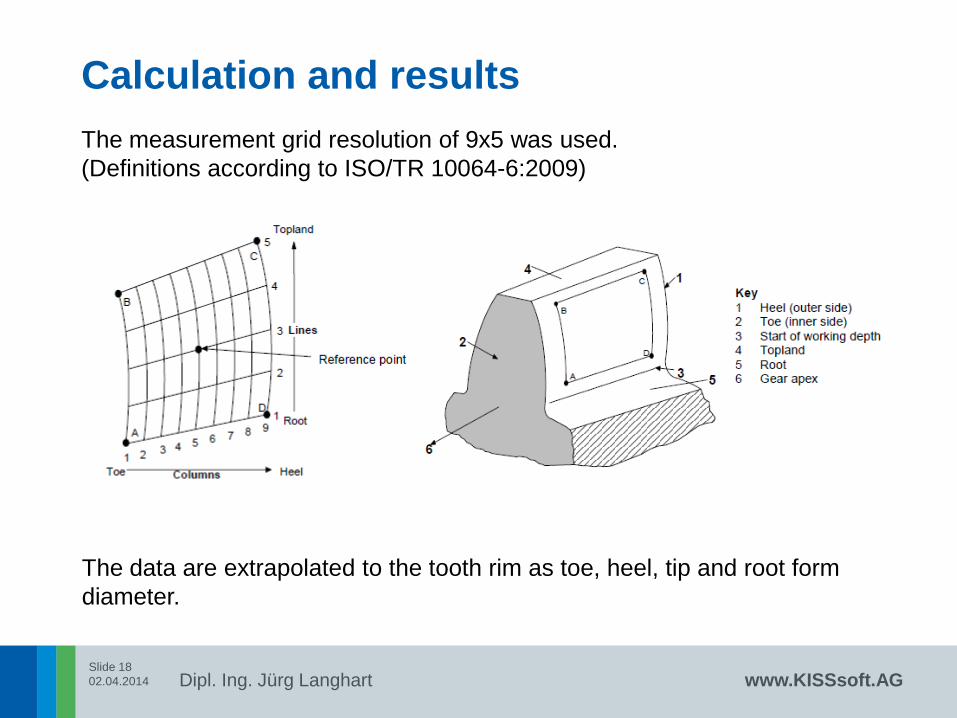
Calculation and results
The measurement grid resolution of 9x5 was used.
(Definitions according to ISO/TR 10064-6:2009)
The data are extrapolated to the tooth rim as toe, heel, tip and root form
diameter.
Slide 19
02.04.2014
Dipl. Ing. Jürg Langhart www.KISSsoft.AG
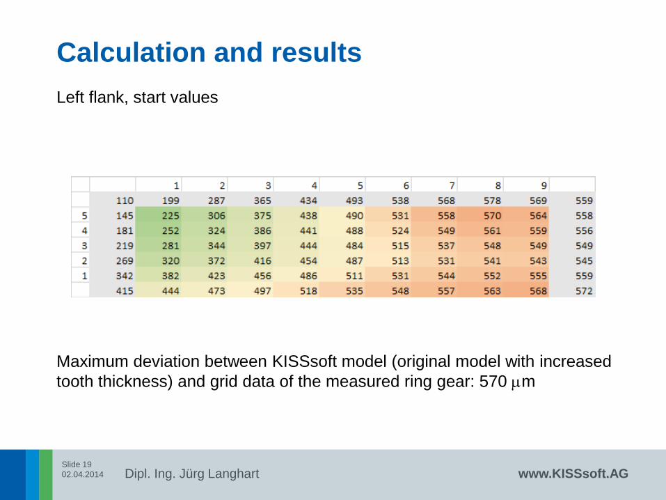
Calculation and results
Left flank, start values
Maximum deviation between KISSsoft model (original model with increased
tooth thickness) and grid data of the measured ring gear: 570 mm

Slide 20
02.04.2014
Dipl. Ing. Jürg Langhart www.KISSsoft.AG
Calculation and results
Left flank, final values
Remaining deviation between KISSsoft model (modified model with
topological modification) and grid data of the measured ring gear: 5 mm

Slide 21
02.04.2014
Dipl. Ing. Jürg Langhart www.KISSsoft.AG
Calculation and results
Right flank, start values
Maximum deviation between KISSsoft model (original model with increased
tooth thickness) and grid data of the measured ring gear: 575 mm
Slide 22
02.04.2014
Dipl. Ing. Jürg Langhart www.KISSsoft.AG
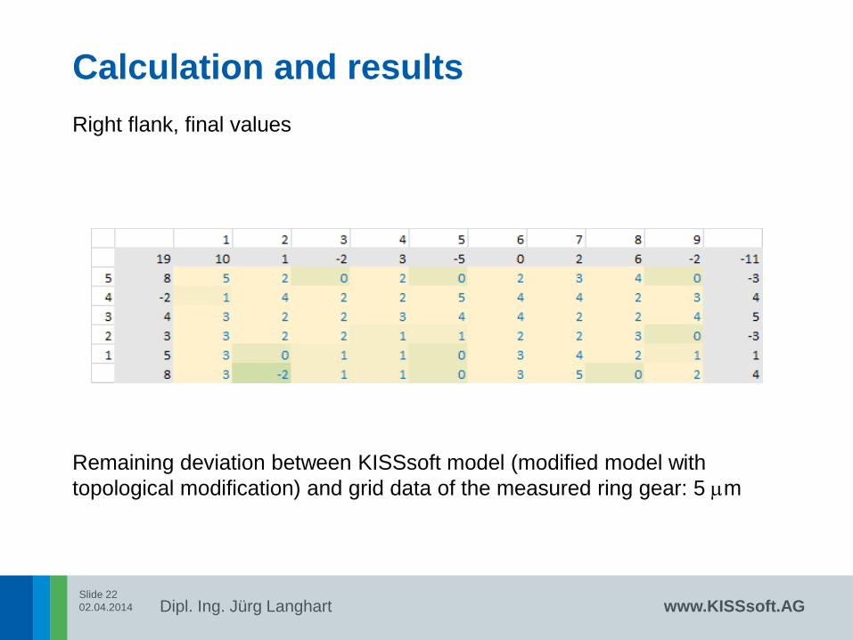
Calculation and results
Right flank, final values
Remaining deviation between KISSsoft model (modified model with
topological modification) and grid data of the measured ring gear: 5 mm

Slide 23
02.04.2014
Dipl. Ing. Jürg Langhart www.KISSsoft.AG
Measuring and rolling
The ring gear was measured on a coordinate measuring machine and
rolled with the pinion.

Slide 24
02.04.2014
Dipl. Ing. Jürg Langhart www.KISSsoft.AG
Measuring and rolling
Drive side Coast side

Slide 25
02.04.2014
Dipl. Ing. Jürg Langhart www.KISSsoft.AG
Conclusion and outlook
It was shown how to pair successfully a conventionally produced pinion with
a 5-Axis milled ring gear.
Therefore, the specific topology of the conventional cutting method were
applied to the model for 5-Axis milling.
This approach uses measuring grid data of existing bevel gears. The
method is also applicable for general milling corrections or the
compensation heat distortion:

Slide 26
02.04.2014
Dipl. Ing. Jürg Langhart
Thank you for your
attention!
WISSEN TEILEN