
PRODUCT SPECIFICATION - Mouser Electronics€¦ · See the Terminal Product Specification listed in...
14
PRODUCT SPECIFICATION REVISION: ECR/ECN INFORMATION: TITLE: MX150 DUAL ROW SEALED ASSEMBLY MAT SEAL SHEET No. F12 EC No: 114393 1 of 14 DATE: 3/10/2017 DOCUMENT NUMBER: CREATED / REVISED BY: CHECKED BY: APPROVED BY: PS-33472-000 M. KOWALSKY M. VANSLAMBROUCK K. DEKOSKI TEMPLATE FILENAME: ENGINEERING_SPEC[SIZE_A](V.1).DOC MX150 DUAL ROW SEALED ASSEMBLY MAT SEAL
Transcript of PRODUCT SPECIFICATION - Mouser Electronics€¦ · See the Terminal Product Specification listed in...

PRODUCT SPECIFICATION
REVISION: ECR/ECN INFORMATION: TITLE: MX150 DUAL ROW SEALED ASSEMBLY
MAT SEAL
SHEET No.
F12 EC No: 114393
1 of 14 DATE: 3/10/2017
DOCUMENT NUMBER: CREATED / REVISED BY: CHECKED BY: APPROVED BY:
PS-33472-000 M. KOWALSKY M. VANSLAMBROUCK K. DEKOSKI
TEMPLATE FILENAME: ENGINEERING_SPEC[SIZE_A](V.1).DOC
MX150 DUAL ROW SEALED ASSEMBLY
MAT SEAL
PRODUCT SPECIFICATION
REVISION: ECR/ECN INFORMATION: TITLE: MX150 DUAL ROW SEALED ASSEMBLY
MAT SEAL
SHEET No.
F12 EC No: 114393
2 of 14 DATE: 3/10/2017
DOCUMENT NUMBER: CREATED / REVISED BY: CHECKED BY: APPROVED BY:
PS-33472-000 M. KOWALSKY M. VANSLAMBROUCK K. DEKOSKI
TEMPLATE FILENAME: ENGINEERING_SPEC[SIZE_A](V.1).DOC
Table of Contents 1.0 Scope .................................................................................................................................................... 3 2.0 Product Description................................................................................................................................ 3
2.1. Direct Connect (wire to board application) .......................................................................................... 3 2.2. Inline Applications (wire to wire application) ....................................................................................... 3 2.3. Receptacle Assembly ......................................................................................................................... 4 2.4. Blade Assembly ................................................................................................................................. 4 2.5. Product Name and Series Number ..................................................................................................... 5
3.0 Integral Components and Accessories ................................................................................................... 6 3.1. Integral Components .......................................................................................................................... 6
3.1.1. Receptacle Terminals ................................................................................................................. 6 3.1.2. Blade Terminals ......................................................................................................................... 7 3.1.3. Applicable Wires ........................................................................................................................ 7
3.1.3.1. Wire size ................................................................................................................................ 7 3.1.3.2. ISO Wire ................................................................................................................................. 7 3.1.3.3. SAE Wire ................................................................................................................................ 8
3.1.4. Terminal Service Tool ................................................................................................................ 8 3.2. Accessories ....................................................................................................................................... 8
3.2.1. Wire Harness Retention Clip - Recommended ........................................................................... 8 3.2.2. Backshell - Recommended ......................................................................................................... 8 3.2.3. Cavity (Seal) Plugs ..................................................................................................................... 8
4.0 Applicable Documents and Specifications .............................................................................................. 8 5.0 Ratings .................................................................................................................................................. 9
5.1. Voltage - Operating ............................................................................................................................ 9 5.2. Voltage - Isolation Resistance ............................................................................................................ 9 5.3. Current Rating.................................................................................................................................... 9 5.4. Temperature ...................................................................................................................................... 9 5.5. Sealing ............................................................................................................................................... 9 5.6. Flammability ..................................................................................................................................... 10 5.7. Dielectric Withstand Strength ........................................................................................................... 10
6.0 Performance ........................................................................................................................................ 10 6.1. Electrical Requirements ................................................................................................................... 10 6.2. Mechanical Requirements ................................................................................................................ 11
6.2.1. Mechanical Requirements Deviations ....................................................................................... 12 6.3. Environmental Requirements ........................................................................................................... 13
7.0 Packaging ............................................................................................................................................ 14 8.0 Gages and Fixtures.............................................................................................................................. 14 9.0 Other Information ................................................................................................................................. 14

PRODUCT SPECIFICATION
REVISION: ECR/ECN INFORMATION: TITLE: MX150 DUAL ROW SEALED ASSEMBLY
MAT SEAL
SHEET No.
F12 EC No: 114393
3 of 14 DATE: 3/10/2017
DOCUMENT NUMBER: CREATED / REVISED BY: CHECKED BY: APPROVED BY:
PS-33472-000 M. KOWALSKY M. VANSLAMBROUCK K. DEKOSKI
TEMPLATE FILENAME: ENGINEERING_SPEC[SIZE_A](V.1).DOC
1.0 SCOPE This product specification covers the 3.50 mm (0.138 inch) centerline (pitch) mat seal dual row MX150 sealed product line connection system. The MX150 connection system uses crimp technology.
2.0 PRODUCT DESCRIPTION
2.1. DIRECT CONNECT (WIRE TO BOARD APPLICATION)
2.2. INLINE APPLICATIONS (WIRE TO WIRE APPLICATION)

PRODUCT SPECIFICATION
REVISION: ECR/ECN INFORMATION: TITLE: MX150 DUAL ROW SEALED ASSEMBLY
MAT SEAL
SHEET No.
F12 EC No: 114393
4 of 14 DATE: 3/10/2017
DOCUMENT NUMBER: CREATED / REVISED BY: CHECKED BY: APPROVED BY:
PS-33472-000 M. KOWALSKY M. VANSLAMBROUCK K. DEKOSKI
TEMPLATE FILENAME: ENGINEERING_SPEC[SIZE_A](V.1).DOC
2.3. RECEPTACLE ASSEMBLY
2.4. BLADE ASSEMBLY
PRODUCT SPECIFICATION
REVISION: ECR/ECN INFORMATION: TITLE: MX150 DUAL ROW SEALED ASSEMBLY
MAT SEAL
SHEET No.
F12 EC No: 114393
5 of 14 DATE: 3/10/2017
DOCUMENT NUMBER: CREATED / REVISED BY: CHECKED BY: APPROVED BY:
PS-33472-000 M. KOWALSKY M. VANSLAMBROUCK K. DEKOSKI
TEMPLATE FILENAME: ENGINEERING_SPEC[SIZE_A](V.1).DOC
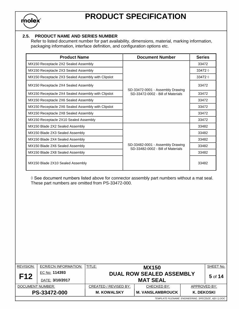
2.5. PRODUCT NAME AND SERIES NUMBER Refer to listed document number for part availability, dimensions, material, marking information, packaging information, interface definition, and configuration options etc.
Product Name Document Number Series
MX150 Receptacle 2X2 Sealed Assembly
SD-33472-0001 - Assembly Drawing SD-33472-0002 - Bill of Materials
33472
MX150 Receptacle 2X3 Sealed Assembly 33472 ◊
MX150 Receptacle 2X3 Sealed Assembly with Clipslot 33472 ◊
MX150 Receptacle 2X4 Sealed Assembly 33472
MX150 Receptacle 2X4 Sealed Assembly with Clipslot 33472
MX150 Receptacle 2X6 Sealed Assembly 33472
MX150 Receptacle 2X6 Sealed Assembly with Clipslot 33472
MX150 Receptacle 2X8 Sealed Assembly 33472
MX150 Receptacle 2X10 Sealed Assembly 33472
MX150 Blade 2X2 Sealed Assembly
SD-33482-0001 - Assembly Drawing SD-33482-0002 - Bill of Materials
33482
MX150 Blade 2X3 Sealed Assembly 33482
MX150 Blade 2X4 Sealed Assembly 33482
MX150 Blade 2X6 Sealed Assembly 33482
MX150 Blade 2X8 Sealed Assembly 33482
MX150 Blade 2X10 Sealed Assembly 33482
◊ See document numbers listed above for connector assembly part numbers without a mat seal. These part numbers are omitted from PS-33472-000.
PRODUCT SPECIFICATION
REVISION: ECR/ECN INFORMATION: TITLE: MX150 DUAL ROW SEALED ASSEMBLY
MAT SEAL
SHEET No.
F12 EC No: 114393
6 of 14 DATE: 3/10/2017
DOCUMENT NUMBER: CREATED / REVISED BY: CHECKED BY: APPROVED BY:
PS-33472-000 M. KOWALSKY M. VANSLAMBROUCK K. DEKOSKI
TEMPLATE FILENAME: ENGINEERING_SPEC[SIZE_A](V.1).DOC
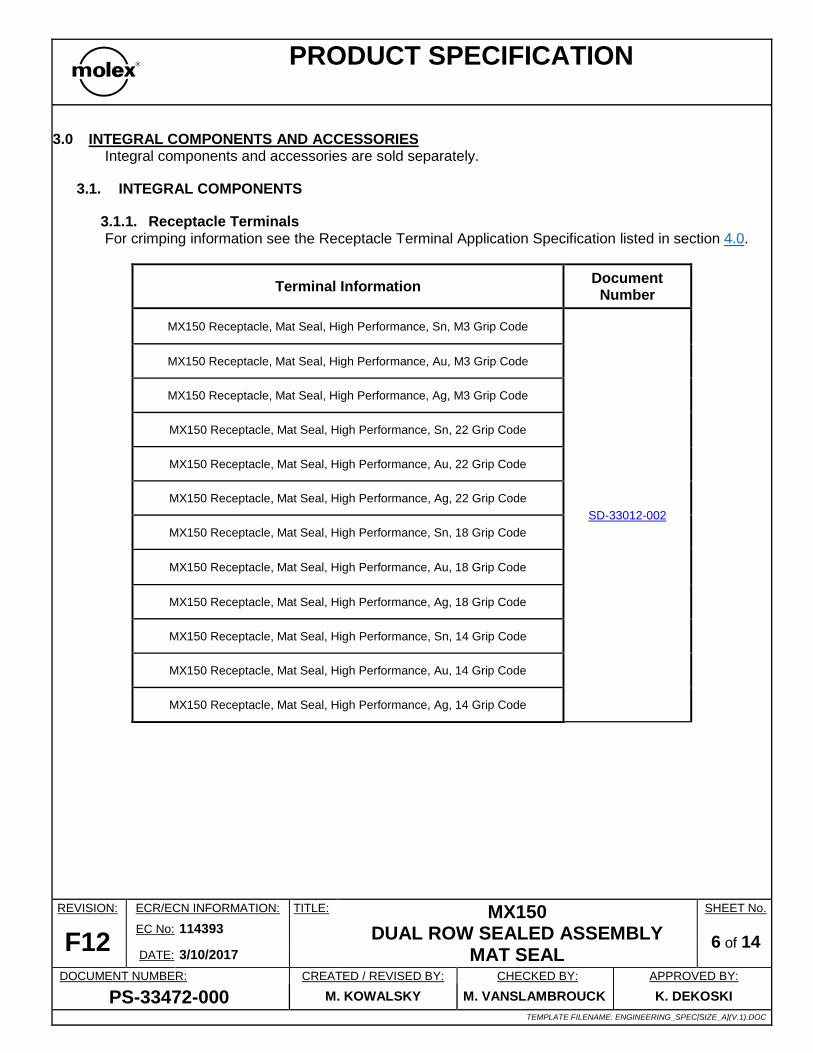
3.0 INTEGRAL COMPONENTS AND ACCESSORIES Integral components and accessories are sold separately.
3.1. INTEGRAL COMPONENTS
3.1.1. Receptacle Terminals For crimping information see the Receptacle Terminal Application Specification listed in section 4.0.
Terminal Information Document
Number
MX150 Receptacle, Mat Seal, High Performance, Sn, M3 Grip Code
SD-33012-002
MX150 Receptacle, Mat Seal, High Performance, Au, M3 Grip Code
MX150 Receptacle, Mat Seal, High Performance, Ag, M3 Grip Code
MX150 Receptacle, Mat Seal, High Performance, Sn, 22 Grip Code
MX150 Receptacle, Mat Seal, High Performance, Au, 22 Grip Code
MX150 Receptacle, Mat Seal, High Performance, Ag, 22 Grip Code
MX150 Receptacle, Mat Seal, High Performance, Sn, 18 Grip Code
MX150 Receptacle, Mat Seal, High Performance, Au, 18 Grip Code
MX150 Receptacle, Mat Seal, High Performance, Ag, 18 Grip Code
MX150 Receptacle, Mat Seal, High Performance, Sn, 14 Grip Code
MX150 Receptacle, Mat Seal, High Performance, Au, 14 Grip Code
MX150 Receptacle, Mat Seal, High Performance, Ag, 14 Grip Code

PRODUCT SPECIFICATION
REVISION: ECR/ECN INFORMATION: TITLE: MX150 DUAL ROW SEALED ASSEMBLY
MAT SEAL
SHEET No.
F12 EC No: 114393
7 of 14 DATE: 3/10/2017
DOCUMENT NUMBER: CREATED / REVISED BY: CHECKED BY: APPROVED BY:
PS-33472-000 M. KOWALSKY M. VANSLAMBROUCK K. DEKOSKI
TEMPLATE FILENAME: ENGINEERING_SPEC[SIZE_A](V.1).DOC
3.1.2. Blade Terminals For crimping information see the Blade Terminal Application Specification listed in section 4.0.
Terminal Information Document
Number
MX150 Blade Mat Seal, High Performance, Sn, M3 Grip Code
SD-33000-001
MX150 Blade Mat Seal, High Performance, Au, M3 Grip Code
MX150 Blade Mat Seal, High Performance, Ag, M3 Grip Code
MX150 Blade Mat Seal, High Performance, Sn, 22 Grip Code
MX150 Blade Mat Seal, High Performance, Au, 22 Grip Code
MX150 Blade Mat Seal, High Performance, Ag, 22 Grip Code
MX150 Blade Mat Seal, High Performance, Sn, 18 Grip Code
MX150 Blade Mat Seal, High Performance, Au, 18 Grip Code
MX150 Blade Mat Seal, High Performance, Ag, 18 Grip Code
MX150 Blade Mat Seal, High Performance, Sn, 14 Grip Code
MX150 Blade Mat Seal, High Performance, Au, 14 Grip Code
MX150 Blade Mat Seal, High Performance, Ag, 14 Grip Code
3.1.3. Applicable Wires 3.1.3.1. Wire size
See section 5.5 for wire range recommended per circuit size.
3.1.3.2. ISO Wire Per the listed wire specifications where the insulation diameter is within 1.20mm to 2.40mm.
- GMW15626 February 2008 - ES-AU5T-1A348-AA Rev D
PRODUCT SPECIFICATION
REVISION: ECR/ECN INFORMATION: TITLE: MX150 DUAL ROW SEALED ASSEMBLY
MAT SEAL
SHEET No.
F12 EC No: 114393
8 of 14 DATE: 3/10/2017
DOCUMENT NUMBER: CREATED / REVISED BY: CHECKED BY: APPROVED BY:
PS-33472-000 M. KOWALSKY M. VANSLAMBROUCK K. DEKOSKI
TEMPLATE FILENAME: ENGINEERING_SPEC[SIZE_A](V.1).DOC
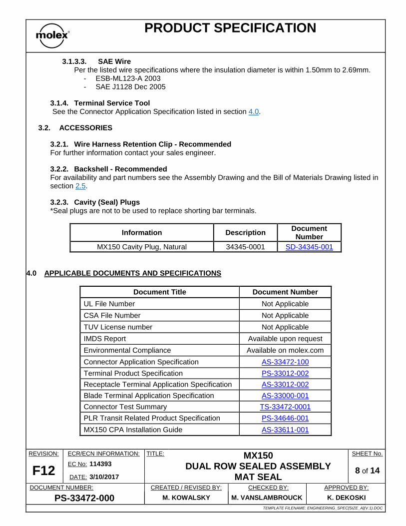
3.1.3.3. SAE Wire Per the listed wire specifications where the insulation diameter is within 1.50mm to 2.69mm.
- ESB-ML123-A 2003 - SAE J1128 Dec 2005
3.1.4. Terminal Service Tool See the Connector Application Specification listed in section 4.0.
3.2. ACCESSORIES
3.2.1. Wire Harness Retention Clip - Recommended For further information contact your sales engineer.
3.2.2. Backshell - Recommended For availability and part numbers see the Assembly Drawing and the Bill of Materials Drawing listed in section 2.5.
3.2.3. Cavity (Seal) Plugs *Seal plugs are not to be used to replace shorting bar terminals.
Information Description Document
Number
MX150 Cavity Plug, Natural 34345-0001 SD-34345-001
4.0 APPLICABLE DOCUMENTS AND SPECIFICATIONS
Document Title Document Number
UL File Number Not Applicable
CSA File Number Not Applicable
TUV License number Not Applicable
IMDS Report Available upon request
Environmental Compliance Available on molex.com
Connector Application Specification AS-33472-100
Terminal Product Specification PS-33012-002
Receptacle Terminal Application Specification AS-33012-002
Blade Terminal Application Specification AS-33000-001
Connector Test Summary TS-33472-0001
PLR Transit Related Product Specification PS-34646-001
MX150 CPA Installation Guide AS-33611-001

PRODUCT SPECIFICATION
REVISION: ECR/ECN INFORMATION: TITLE: MX150 DUAL ROW SEALED ASSEMBLY
MAT SEAL
SHEET No.
F12 EC No: 114393
9 of 14 DATE: 3/10/2017
DOCUMENT NUMBER: CREATED / REVISED BY: CHECKED BY: APPROVED BY:
PS-33472-000 M. KOWALSKY M. VANSLAMBROUCK K. DEKOSKI
TEMPLATE FILENAME: ENGINEERING_SPEC[SIZE_A](V.1).DOC
5.0 RATINGS
5.1. VOLTAGE - OPERATING Operating Voltage: 14 Volts DC Maximum
5.2. VOLTAGE - ISOLATION RESISTANCE 100MΩ Minimum when 500 Volts DC between adjacent terminals and terminals to ground.
5.3. CURRENT RATING See the Terminal Product Specification listed in section 4.0.
5.4. TEMPERATURE Non-operating: - 40 Cº to + 125 Cº Operating: - 40 Cº to + 125 Cº
5.5. SEALING - Meets IP67 - Meets IPx9K when the following configuration is used.
- With CPA - With Backshell - With Convoluted Conduit
Circuit Size
Part Numbers
Wire Range
2x2
ALL except
33472-04XX 33472-44XX 33482-04XX 33482-44XX
1.20-2.69 mm (0.047–0.106 in)
2X3
ALL ◊ 2X4
2X6
2X8
2X10
33482-21xx – 33482-2999
33472-2xxx
2X2
33472-04XX 33472-44XX 33482-04XX 33482-44XX
1.40-2.69 mm (0.055–0.106 in)
2X10 33482-20xx
◊ See document numbers listed in section 2.5 for connector assembly part numbers without a mat seal. These part numbers are omitted from PS-33472-000.

PRODUCT SPECIFICATION
REVISION: ECR/ECN INFORMATION: TITLE: MX150 DUAL ROW SEALED ASSEMBLY
MAT SEAL
SHEET No.
F12 EC No: 114393
10 of 14 DATE: 3/10/2017
DOCUMENT NUMBER: CREATED / REVISED BY: CHECKED BY: APPROVED BY:
PS-33472-000 M. KOWALSKY M. VANSLAMBROUCK K. DEKOSKI
TEMPLATE FILENAME: ENGINEERING_SPEC[SIZE_A](V.1).DOC
- Product Performance Is Based On Connector Requirements Per GMW3191 Dec 2007 - Sealing Performance
◊ Backshells are one time use only. This condition may cause reduced backshell retention post-test.
5.6. FLAMMABILITY The burn rate of the plastic material when tested to ISO 3795 shall not exceed 100 mm/min.
5.7. DIELECTRIC WITHSTAND STRENGTH Connectors withstand 1500V AC between adjacent terminals for 1 minute. Test performed with the following conditions.
- MX150 2X4 Connector - JIS C5402 5.1/MIL-STD-202 Method 301
- UL1007 AWG18
6.0 PERFORMANCE - Additional circuit sizes added to the product family are validated per USCAR-2 Rev. 4 Appendix D.
6.1. ELECTRICAL REQUIREMENTS
ITEM FUNCTION DESCRIPTION REQUIREMENT
1 Contact
Resistance
(Low Level)
Mate connectors: limiting the open circuit
voltage of 20 mV and a maximum current of
100 mA.
10 milliohms
MAXIMUM
2
Contact
Resistance
@ Rated Current
(Voltage Drop)
Mate connectors: apply a 5 ampere/ 1.0 mm2
current
10 milliohms
MAXIMUM
3 Isolation
Resistance
Apply a voltage of 500 VDC between
adjacent terminals and between terminals to
ground.
20 Meg ohms
MINIMUM
4 Temperature
Rise
(via Current Cycling)
Mate terminals: measure the temperature
rise at the rated current after:
1008 hours of bench top testing
(45 minutes ON and 15 minutes OFF per
hour).
Temperature rise over
Ambient:
+55 Cº MAXIMUM
Circuit Size
Operating Conditions Additional Required
Component
1x2 Sealing Class III
Temperature Class III Convolute
CPA

PRODUCT SPECIFICATION
REVISION: ECR/ECN INFORMATION: TITLE: MX150 DUAL ROW SEALED ASSEMBLY
MAT SEAL
SHEET No.
F12 EC No: 114393
11 of 14 DATE: 3/10/2017
DOCUMENT NUMBER: CREATED / REVISED BY: CHECKED BY: APPROVED BY:
PS-33472-000 M. KOWALSKY M. VANSLAMBROUCK K. DEKOSKI
TEMPLATE FILENAME: ENGINEERING_SPEC[SIZE_A](V.1).DOC
6.2. MECHANICAL REQUIREMENTS
ITEM FUNCTION DESCRIPTION REQUIREMENT
5 Connector Mate/
Unmate Forces Mate and unmate connector (male to female).
75 Newtons MAXIMUM
Unmate 110 Newtons
MINIMUM
6
Terminal
Retention Force
(in Housing)
Axial pullout force on the terminal in the
housing. 90 Newtons MINIMUM
7 Terminal
Insertion Force
(into Housing)
Apply an axial insertion force on the terminal. 30 Newtons MAXIMUM
8 Connector Audible
Feedback
The connector lock must provide audible
feedback during connector mating. 7dB over Ambient (C scale)
9 Polarization Feature
Effectiveness
Connector must be polarized to prevent
mating with similar connectors or incorrect
orientation
220 Newtons MINIMUM
10
Terminal Position
Assurance (TPA)
Insertion Force (into
housing)
The force to insert the TPA from the preload
(as shipped) position to the final position. 60 Newtons MAXIMUM
11
Terminal Position
Assurance (TPA)
Extraction Force (in
housing)
The force to extract the TPA from the final
position to the preload position (as shipped). 60 Newtons MAXIMUM
12
Connector Position
Assurance (CPA)
Insertion Force (into
housing)
The force to insert the CPA from the preload
(as shipped) position to the final position.
40 Newtons MINIMUM
(unmated)
22 Newtons MAXIMUM
(fully mated)
13
Connector Position
Assurance (CPA)
Disengage Force (in
housing)
The force to disengage the CPA from the
final position to the preload (as shipped)
position.
3 Newtons MINIMUM
40 Newtons MAXIMUM
14
Connector Position
Assurance (CPA)
Extraction Force (in
housing)
The force to disengage the CPA from the
final position to the preload (as shipped)
position.
30 Newtons MINIMUM
15 Locator Clip
Insertion Force (in
housing)
The force to insert the locator clip to the final
position. 60 Newtons MAXIMUM

PRODUCT SPECIFICATION
REVISION: ECR/ECN INFORMATION: TITLE: MX150 DUAL ROW SEALED ASSEMBLY
MAT SEAL
SHEET No.
F12 EC No: 114393
12 of 14 DATE: 3/10/2017
DOCUMENT NUMBER: CREATED / REVISED BY: CHECKED BY: APPROVED BY:
PS-33472-000 M. KOWALSKY M. VANSLAMBROUCK K. DEKOSKI
TEMPLATE FILENAME: ENGINEERING_SPEC[SIZE_A](V.1).DOC
16 Locator Clip
Extraction Force (in
housing)
The force to extract the locator clip from the
final position to out. 110 Newtons MINIMUM
6.2.1. Mechanical Requirements Deviations
ITEM FUNCTION DESCRIPTION CKT BLADE/ RCPT
REQUIREMENT
7
Terminal
Insertion Force for
Wire Diameter above
2.5mm not
exceeding 2.69mm
(into Housing)
Apply an axial insertion force on the
terminal. ALL
BLADE 45 Newtons
MAXIMUM
RCPT 40 Newtons
MAXIMUM
10
Terminal Position
Assurance (TPA)
Insertion Force (into
housing)
The force to insert the TPA from the
preload (as shipped) position to the final
position.
2X2 RCPT 90 Newtons
MAXIMUM
11
Terminal Position
Assurance (TPA)
Extraction Force (in
housing)
The force to extract the TPA from the
final position to the preload position (as
shipped).
2X2
RCPT
90 Newtons
MAXIMUM
2X3 130 Newtons
MAXIMUM 2x4
2X10
BLADE 75 Newtons
MAXIMUM
RCPT 130 Newtons
MAXIMUM
13
Connector Position
Assurance (CPA)
Extraction Force (in
housing)
The force to extract the CPA from the
final position to the preload position. ALL RCPT
40 Newtons
MAXIMUM
3 Newtons
MINIMUM

PRODUCT SPECIFICATION
REVISION: ECR/ECN INFORMATION: TITLE: MX150 DUAL ROW SEALED ASSEMBLY
MAT SEAL
SHEET No.
F12 EC No: 114393
13 of 14 DATE: 3/10/2017
DOCUMENT NUMBER: CREATED / REVISED BY: CHECKED BY: APPROVED BY:
PS-33472-000 M. KOWALSKY M. VANSLAMBROUCK K. DEKOSKI
TEMPLATE FILENAME: ENGINEERING_SPEC[SIZE_A](V.1).DOC
6.3. ENVIRONMENTAL REQUIREMENTS
ITEM FUNCTION DESCRIPTION REQUIREMENT
16 Field Correlated Life
Test (FCLT)
Mate connectors up to 1 cycle and expose to
environment per SAE/USCAR-20. 20 milliohms MAXIMUM
17 Durability Mate connectors up to 10 cycles prior to
environmental tests.
10 milliohms MAXIMUM
&
Discontinuity < 1 microsecond
18 Thermal Shock
(Electrical)
Mate connectors per durability; expose to
100 cycles of:
Temperature C° Duration (Minutes)
-40 +0/-3 30
+125 +3/-0 30
10 milliohms MAXIMUM
&
Discontinuity < 1 microsecond
19 High Temperature
Exposure
(Sealing)
Mate connectors per durability and expose to
1008 hours at 125 ± 2°C
28 kPa for 15 seconds
MINIMUM pressure/vacuum
&
Submersion for 30 minutes
&
Isolation Resistance of 20 Meg
ohms @ 500 VDC MINIMUM
20 Temperature/
Humidity
(Sealing)
Mate connectors per durability and expose
connector system to forty 8-hour cycles of
combined heating and humidity exposure
–40 ºC and 125 ºC at 0% to 90% RH
28 kPa for 15 seconds
MINIMUM pressure/vacuum
&
Submersion for 30 minutes
&
Isolation Resistance of 20 Meg
ohms @ 500 VDC MINIMUM
21 Fluid Resistance
(Sealing)
Submerge connector assemblies in the
following fluids: gasoline, *diesel fuel, engine
oil, ethanol, power steering fluid, automatic
transmission fluid, engine coolant, and brake
fluid.
Submersion for 30 minutes
&
Isolation Resistance of 20 Meg
ohms @ 500 VDC MINIMUM
22 Vibration/
Mechanical Shock
(Electrical)
Mate connectors per durability. Connector
assembly shall be vibrated for (8 hours /
axes @ 12.1 Grms, 10 shocks @ 35 Gs /
axes) Coupled to engine.
10 milliohms MAXIMUM
&
Discontinuity < 1 microsecond
* Silicone seals swell in the presence of gasoline and diesel fuel. This condition may cause excessive connector mate/unmate forces and/or reduce the Grommet Cap retention.

PRODUCT SPECIFICATION
REVISION: ECR/ECN INFORMATION: TITLE: MX150 DUAL ROW SEALED ASSEMBLY
MAT SEAL
SHEET No.
F12 EC No: 114393
14 of 14 DATE: 3/10/2017
DOCUMENT NUMBER: CREATED / REVISED BY: CHECKED BY: APPROVED BY:
PS-33472-000 M. KOWALSKY M. VANSLAMBROUCK K. DEKOSKI
TEMPLATE FILENAME: ENGINEERING_SPEC[SIZE_A](V.1).DOC
7.0 PACKAGING - Molex packaging drawing numbers are located on the Assembly Drawing listed in section 2.5. - Parts should be packaged to protect against damage during handling, transit and storage.
8.0 GAGES AND FIXTURES All applicable gages and fixtures are referenced in the appropriate control plans.
9.0 OTHER INFORMATION - Products confirm to USCAR-2 class III environment. - ◊ See document numbers listed in section 2.5 for connector assembly part numbers without a mat seal. These part numbers are omitted from PS-33472-000. - To add new knock out patterns contact your sales engineer.
MOLEX REPRESENTS AND WARRANTS TO BUYER FOR A PERIOD OF ONE (1) YEAR FROM THE DATE OF DELIVERY OF THE PRODUCTS TO BUYER THAT 1) THE PRODUCTS SHALL CONFORM TO THE MOLEX SPECIFICATIONS FOR THE PRODUCTS IN FORCE AT THE DATE OF DELIVERY OF THE
PRODUCTS TO BUYER, AND 2) THE PRODUCTS SHALL BE OF FREE FROM MATERIAL DEFECTS IN MATERIALS AND MANUFACTURING. EXCEPT AS EXPRESSLY PROVIDED ABOVE, MOLEX MAKES NO WARRANTY, EXPRESS OR IMPLIED, REGARDING THE PRODUCTS. ALL IMPLIED WARRANTIES, INCLUDING, BUT NOT LIMITED TO, THE IMPLIED WARRANTIES OF FITNESS FOR A PARTICULAR PURPOSE, ARE HEREBY DISCLAIMED. IN ADDITION, MOLEX EXPRESSLY DISCLAIMS ANY WARRANTY OBLIGATIONS IN THOSE INSTANCES WHERE THE FAILURES RESULTED FROM THE MODIFICATION OF THE PRODUCTS BY BUYER OR ITS CUSTOMERS, IMPROPER HANDLING, USE OR INSTALLATION OF THE PRODUCTS BY BUYER OR ITS CUSTOMERS, OR ANY OTHER CAUSE BEYOND THE CONTROL OF MOLEX.