PRODUCT SELECTION LOCATOR - WIMA · SPECIFICATION # PRODUCT DESCRIPTION REVISION DATE 1050 CHTC®...
186
Phone: 888-593-3355 www.generalcable.com SECTION SPECIFICATION 1 300V Instrumentation Cables 1000 2 600V Instrumentation Cables 2000 3 600V Flexible Control and Power Cables 3000 4 600V Multi Conductor Control and Power Cables 4000 5 600V Industrial Power Cables 5000 6 2.4kV — 35kV Industrial Medium-Voltage Cables 6000 7 600V — 35kV Industrial Armored Cables 7000 8 600V — 28kV TECK90 Armored Control and Power Cables 8000 Technical Information A – F PRODUCT SELECTION LOCATOR
Transcript of PRODUCT SELECTION LOCATOR - WIMA · SPECIFICATION # PRODUCT DESCRIPTION REVISION DATE 1050 CHTC®...

Phone: 888-593-3355www.generalcable.com
SECTION SPECIFICATION
1 300V Instrumentation Cables 1000
2 600V Instrumentation Cables 2000
3 600V Flexible Control and Power Cables 3000
4 600V Multi Conductor Control and Power Cables 4000
5 600V Industrial Power Cables 5000
6 2.4kV — 35kV Industrial Medium-Voltage Cables 6000
7 600V — 35kV Industrial Armored Cables 7000
8 600V — 28kV TECK90 Armored Control and Power Cables 8000
Technical Information A – F
PRODUCT SELECTION LOCATOR
Phone: 888-593-3355www.generalcable.com
Table of Contents
Date of Issue 01/07
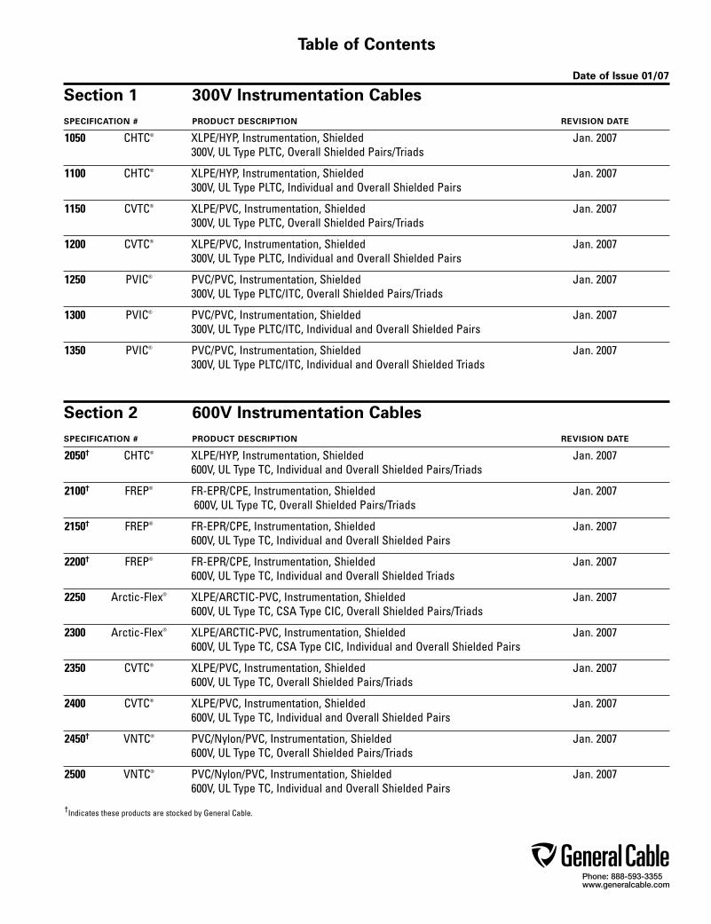
Section 1 300V Instrumentation CablesSPECIFICATION # PRODUCT DESCRIPTION REVISION DATE
1050 CHTC® XLPE/HYP, Instrumentation, Shielded Jan. 2007 300V, UL Type PLTC, Overall Shielded Pairs/Triads
1100 CHTC® XLPE/HYP, Instrumentation, Shielded Jan. 2007 300V, UL Type PLTC, Individual and Overall Shielded Pairs
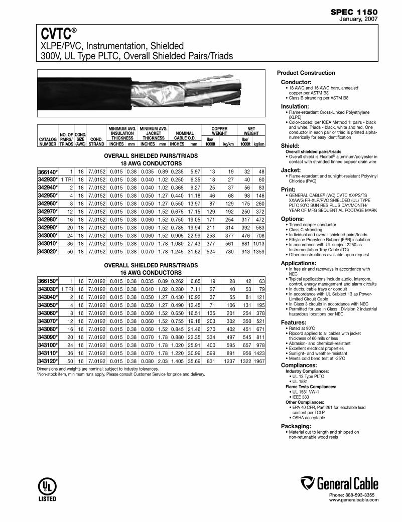
1150 CVTC® XLPE/PVC, Instrumentation, Shielded Jan. 2007 300V, UL Type PLTC, Overall Shielded Pairs/Triads
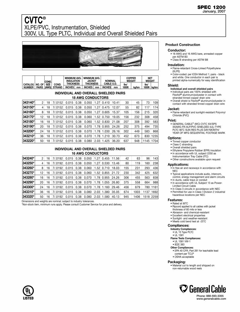
1200 CVTC® XLPE/PVC, Instrumentation, Shielded Jan. 2007 300V, UL Type PLTC, Individual and Overall Shielded Pairs
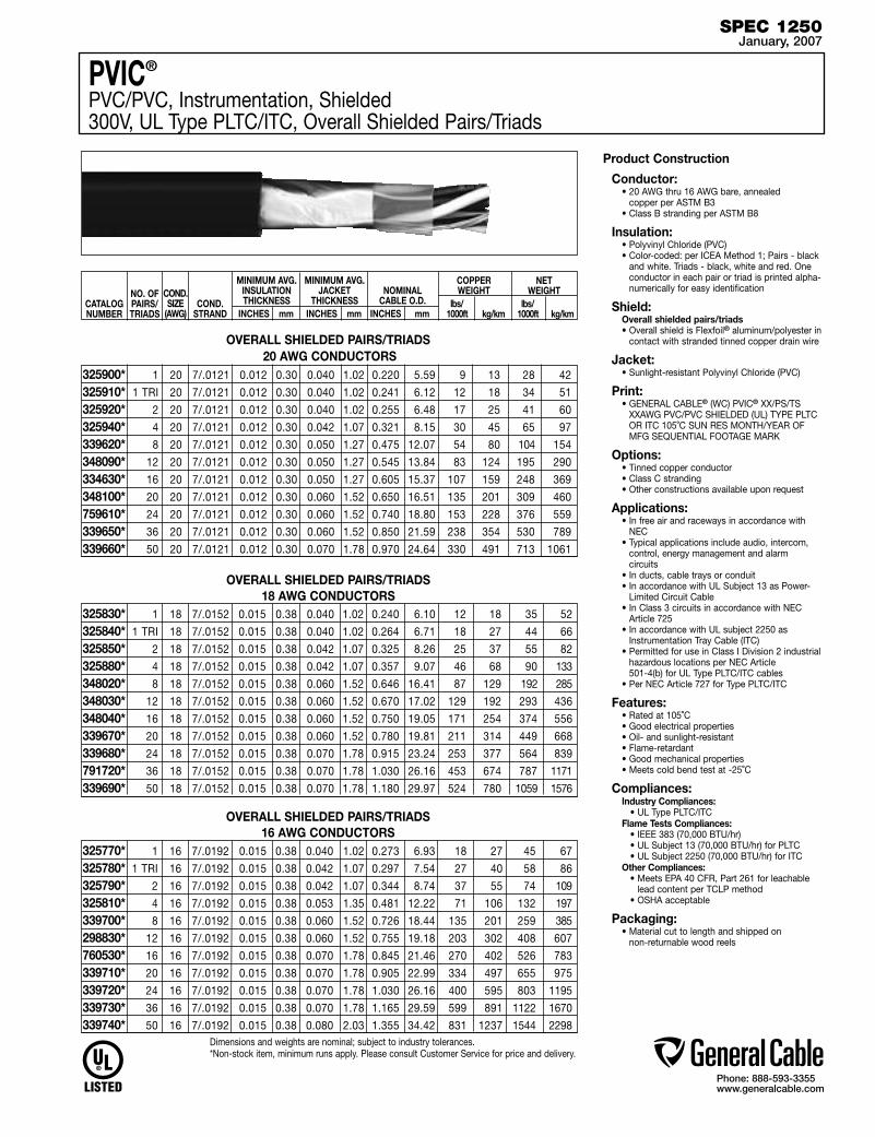
1250 PVIC® PVC/PVC, Instrumentation, Shielded Jan. 2007 300V, UL Type PLTC/ITC, Overall Shielded Pairs/Triads
1300 PVIC® PVC/PVC, Instrumentation, Shielded Jan. 2007 300V, UL Type PLTC/ITC, Individual and Overall Shielded Pairs
1350 PVIC® PVC/PVC, Instrumentation, Shielded Jan. 2007 300V, UL Type PLTC/ITC, Individual and Overall Shielded Triads
Section 2 600V Instrumentation CablesSPECIFICATION # PRODUCT DESCRIPTION REVISION DATE
2050† CHTC® XLPE/HYP, Instrumentation, Shielded Jan. 2007 600V, UL Type TC, Individual and Overall Shielded Pairs/Triads
2100† FREP® FR-EPR/CPE, Instrumentation, Shielded Jan. 2007 600V, UL Type TC, Overall Shielded Pairs/Triads
2150† FREP® FR-EPR/CPE, Instrumentation, Shielded Jan. 2007 600V, UL Type TC, Individual and Overall Shielded Pairs
2200† FREP® FR-EPR/CPE, Instrumentation, Shielded Jan. 2007 600V, UL Type TC, Individual and Overall Shielded Triads
2250 Arctic-Flex® XLPE/ARCTIC-PVC, Instrumentation, Shielded Jan. 2007 600V, UL Type TC, CSA Type CIC, Overall Shielded Pairs/Triads
2300 Arctic-Flex® XLPE/ARCTIC-PVC, Instrumentation, Shielded Jan. 2007 600V, UL Type TC, CSA Type CIC, Individual and Overall Shielded Pairs
2350 CVTC® XLPE/PVC, Instrumentation, Shielded Jan. 2007 600V, UL Type TC, Overall Shielded Pairs/Triads
2400 CVTC® XLPE/PVC, Instrumentation, Shielded Jan. 2007 600V, UL Type TC, Individual and Overall Shielded Pairs
2450† VNTC® PVC/Nylon/PVC, Instrumentation, Shielded Jan. 2007 600V, UL Type TC, Overall Shielded Pairs/Triads
2500 VNTC® PVC/Nylon/PVC, Instrumentation, Shielded Jan. 2007 600V, UL Type TC, Individual and Overall Shielded Pairs
†Indicates these products are stocked by General Cable.
Phone: 888-593-3355www.generalcable.com
Table of Contents
Date of Issue 02/07
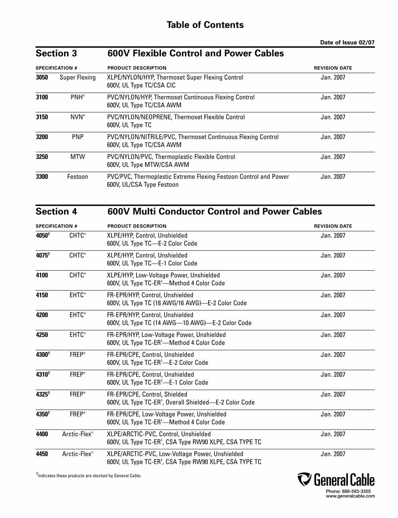
Section 3 600V Flexible Control and Power CablesSPECIFICATION # PRODUCT DESCRIPTION REVISION DATE
3050 Super Flexing XLPE/NYLON/HYP, Thermoset Super Flexing Control Jan. 2007 600V, UL Type TC/CSA CIC
3100 PNH® PVC/NYLON/HYP, Thermoset Continuous Flexing Control Jan. 2007 600V, UL Type TC/CSA AWM
3150 NVN® PVC/NYLON/NEOPRENE, Thermoset Flexible Control Jan. 2007 600V, UL Type TC
3200 PNP PVC/NYLON/NITRILE/PVC, Thermoset Continuous Flexing Control Jan. 2007 600V, UL Type TC/CSA AWM
3250 MTW PVC/NYLON/PVC, Thermoplastic Flexible Control Jan. 2007 600V, UL Type MTW/CSA AWM
3300 Festoon PVC/PVC, Thermoplastic Extreme Flexing Festoon Control and Power Jan. 2007 600V, UL/CSA Type Festoon
Section 4 600V Multi Conductor Control and Power CablesSPECIFICATION # PRODUCT DESCRIPTION REVISION DATE
4050† CHTC® XLPE/HYP, Control, Unshielded Jan. 2007 600V, UL Type TC—E-2 Color Code
4075† CHTC® XLPE/HYP, Control, Unshielded Jan. 2007 600V, UL Type TC—E-1 Color Code
4100 CHTC® XLPE/HYP, Low-Voltage Power, Unshielded Jan. 2007 600V, UL Type TC-ER1—Method 4 Color Code
4150 EHTC® FR-EPR/HYP, Control, Unshielded Jan. 2007 600V, UL Type TC (18 AWG/16 AWG)—E-2 Color Code
4200 EHTC® FR-EPR/HYP, Control, Unshielded Jan. 2007 600V, UL Type TC (14 AWG—10 AWG)—E-2 Color Code
4250 EHTC® FR-EPR/HYP, Low-Voltage Power, Unshielded Jan. 2007 600V, UL Type TC-ER1—Method 4 Color Code
4300† FREP® FR-EPR/CPE, Control, Unshielded Jan. 2007 600V, UL Type TC-ER1—E-2 Color Code
4310† FREP® FR-EPR/CPE, Control, Unshielded Jan. 2007 600V, UL Type TC-ER1—E-1 Color Code
4325† FREP® FR-EPR/CPE, Control, Shielded Jan. 2007 600V, UL Type TC-ER1, Overall Shielded—E-2 Color Code
4350† FREP® FR-EPR/CPE, Low-Voltage Power, Unshielded Jan. 2007 600V, UL Type TC-ER1—Method 4 Color Code
4400 Arctic-Flex® XLPE/ARCTIC-PVC, Control, Unshielded Jan. 2007 600V, UL Type TC-ER1, CSA Type RW90 XLPE, CSA TYPE TC
4450 Arctic-Flex® XLPE/ARCTIC-PVC, Low-Voltage Power, Unshielded Jan. 2007 600V, UL Type TC-ER1, CSA Type RW90 XLPE, CSA TYPE TC
†Indicates these products are stocked by General Cable.

Phone: 888-593-3355www.generalcable.com
Table of Contents
Date of Issue 02/07
Section 4 (con’t.) 600V Multi Conductor Control and Power CablesSPECIFICATION # PRODUCT DESCRIPTION REVISION DATE
4500† CVTC® XLPE/PVC, Control, Unshielded Jan. 2007 600V, UL Type TC-ER1—E-2 Color Code
4550† CVTC® XLPE/PVC, Low-Voltage Power, Unshielded Jan. 2007 600V, UL Type TC-ER1—Method 4 Color Code
4575 CVTC® VFD XLPE/PVC, Low-Voltage Power, Shielded Jan. 2007 2000V, UL Type TC-ER1—Method 4 Color Code
4600† VNTC® PVC/NYLON/PVC, Control, Unshielded Jan. 2007 600V, UL Type TC-ER1 (18 AWG/16 AWG)—E-2 Color Code
4650† VNTC® PVC/NYLON/PVC, Control, Unshielded Jan. 2007 600V, UL Type TC-ER1 (14 AWG—10 AWG)—E-2 Color Code
4700† VNTC® PVC/NYLON/PVC, Control, Shielded Jan. 2007 600V, UL Type TC-ER1, Overall Shielded—E-2 Color Code
4750† VNTC® PVC/NYLON/PVC, Low-Voltage Power, Unshielded Jan. 2007 600V, UL Type TC-ER1—Method 4 Color Code
4800 20/10 PE/PVC/PVC, Control, Unshielded Jan. 2007 600V (18 AWG/16 AWG)—E-1 Color Code
4850 20/10 PE/PVC/PVC, Control, Unshielded Jan. 2007 600V (14 AWG—10 AWG)—E-1 Color Code
Section 5 600V Industrial Power CablesSPECIFICATION # PRODUCT DESCRIPTION REVISION DATE
5050† DuraSheath® EPR/HYP, Low-Voltage Power, Unshielded Jan. 2007 600V, UL Type RHH/RHW-2/USE-2 LS
5100 Unicon® FREP® FR-EPR, Low-Voltage Power, Unshielded Jan. 2007 600V, UL Type RHH/RHW-2/USE-2
5150 XHHW-2 VW-1 XLPE, Control and Low-Voltage Power, Unshielded Jan. 2007 600V, UL Type SIS/XHHW-2, VW-1 Rated
5200† XHHW-2 XLPE, Low-Voltage Power, Unshielded Jan. 2007 600V, UL Type XHHW-2, c(UL) RW-90
5250 Unicon® XLPE XLPE, Low-Voltage Power, Unshielded Jan. 2007 600V, UL Type RHH/RHW-2/USE-2
5300† Super Vu-Tron® EPR/CPE, Diesel Locomotive Cable Jan. 2007 2000V, Type DLO; 600V, UL Type RHH/RHW; 1000V, CSA Type R90
5350† GenPowr™ LSZH XLPO, Low-Smoke, Zero-Halogen (LSZH), Low-Voltage Power, Unshielded Jan. 2007 600V, Type RHH/RHW-LS/USE, CSA AWM I A/B, Class B
5400† GenPowr™ LSZH XLPO, Low-Smoke, Zero-Halogen (LSZH), Low-Voltage Power, Unshielded Jan. 2007 600V, Type RHH/RHW-LS/USE, CSA AWM I A/B, Class I
†Indicates these products are stocked by General Cable.
Phone: 888-593-3355www.generalcable.com
Table of Contents
Date of Issue 01/07
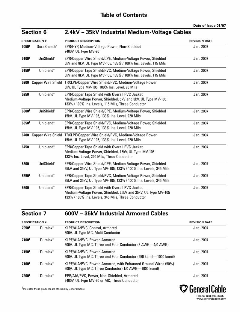
Section 6 2.4kV – 35kV Industrial Medium-Voltage CablesSPECIFICATION # PRODUCT DESCRIPTION REVISION DATE
6050† DuraSheath® EPR/HYP, Medium-Voltage Power, Non-Shielded Jan. 2007 2400V, UL Type MV-90
6100† UniShield® EPR/Copper Wire Shield/CPE, Medium-Voltage Power, Shielded Jan. 2007 5kV and 8kV, UL Type MV-105, 133% / 100% Ins. Levels, 115 Mils
6150† Uniblend® EPR/Copper Tape Shield/PVC, Medium-Voltage Power, Shielded Jan. 2007 5kV and 8kV, UL Type MV-105, 133% / 100% Ins. Levels, 115 Mils
6200 Copper Wire Shield TRXLPE/Copper Wire Shield/PVC, Medium-Voltage Power Jan. 2007 5kV, UL Type MV-105, 100% Ins. Level, 90 Mils
6250 Uniblend® EPR/Copper Tape Shield with Overall PVC Jacket Jan. 2007 Medium-Voltage Power, Shielded, 5kV and 8kV, UL Type MV-105 133% / 100% Ins. Levels, 115 Mils, Three Conductor
6300† UniShield® EPR/Copper Wire Shield/CPE, Medium-Voltage Power, Shielded Jan. 2007 15kV, UL Type MV-105, 133% Ins. Level, 220 Mils
6350† Uniblend® EPR/Copper Tape Shield/PVC, Medium-Voltage Power, Shielded Jan. 2007 15kV, UL Type MV-105, 133% Ins. Level, 220 Mils
6400 Copper Wire Shield TRXLPE/Copper Wire Shield/PVC, Medium-Voltage Power Jan. 2007 15kV, UL Type MV-105, 133% Ins. Level, 220 Mils
6450 Uniblend® EPR/Copper Tape Shield with Overall PVC Jacket Jan. 2007 Medium-Voltage Power, Shielded, 15kV, UL Type MV-105 133% Ins. Level, 220 Mils, Three Conductor
6500 UniShield® EPR/Copper Wire Shield/CPE, Medium-Voltage Power, Shielded Jan. 2007 25kV and 35kV, UL Type MV-105, 133% / 100% Ins. Levels, 345 Mils
6550† Uniblend® EPR/Copper Tape Shield/PVC, Medium-Voltage Power, Shielded Jan. 2007 25kV and 35kV, UL Type MV-105, 133% / 100% Ins. Levels, 345 Mils
6600 Uniblend® EPR/Copper Tape Shield with Overall PVC Jacket Jan. 2007 Medium-Voltage Power, Shielded, 25kV and 35kV, UL Type MV-105 133% / 100% Ins. Levels, 345 Mils, Three Conductor
Section 7 600V – 35kV Industrial Armored CablesSPECIFICATION # PRODUCT DESCRIPTION REVISION DATE
7050† Duralox® XLPE/AIA/PVC, Control, Armored Jan. 2007 600V, UL Type MC, Multi Conductor
7100† Duralox® XLPE/AIA/PVC, Power, Armored Jan. 2007 600V, UL Type MC, Three and Four Conductor (8 AWG—4/0 AWG)
7150† Duralox® XLPE/AIA/PVC, Power, Armored Jan. 2007 600V, UL Type MC, Three and Four Conductor (250 kcmil—1000 kcmil)
7160† Duralox® XLPE/AIA/PVC, Power, Armored, with Enhanced Ground Wires (50%) Jan. 2007 600V, UL Type MC, Three Conductor (1/0 AWG—1000 kcmil)
7200† Duralox® EPR/AIA/PVC, Power, Non-Shielded, Armored Jan. 2007 2400V, UL Type MV-90 or MC, Three Conductor
†Indicates these products are stocked by General Cable.
Phone: 888-593-3355www.generalcable.com
Table of Contents
Date of Issue 01/07
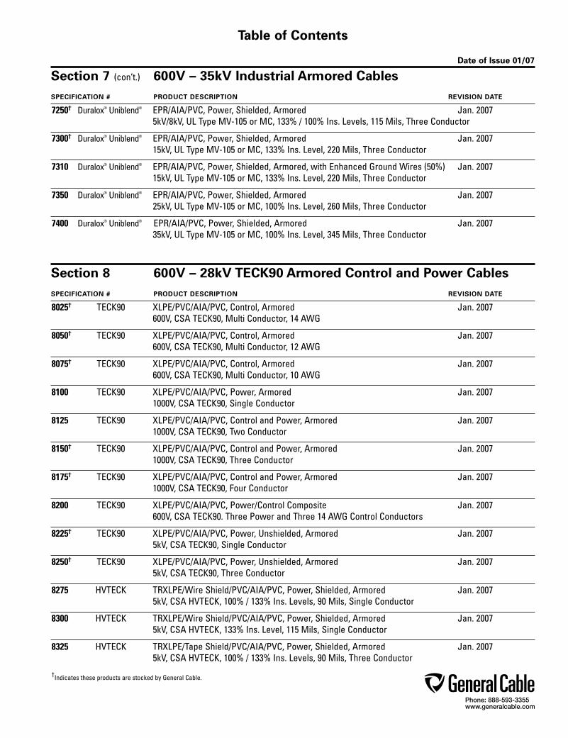
Section 7 (con’t.) 600V – 35kV Industrial Armored CablesSPECIFICATION # PRODUCT DESCRIPTION REVISION DATE
7250† Duralox® Uniblend® EPR/AIA/PVC, Power, Shielded, Armored Jan. 2007 5kV/8kV, UL Type MV-105 or MC, 133% / 100% Ins. Levels, 115 Mils, Three Conductor
7300† Duralox® Uniblend® EPR/AIA/PVC, Power, Shielded, Armored Jan. 2007 15kV, UL Type MV-105 or MC, 133% Ins. Level, 220 Mils, Three Conductor
7310 Duralox® Uniblend® EPR/AIA/PVC, Power, Shielded, Armored, with Enhanced Ground Wires (50%) Jan. 2007 15kV, UL Type MV-105 or MC, 133% Ins. Level, 220 Mils, Three Conductor
7350 Duralox® Uniblend® EPR/AIA/PVC, Power, Shielded, Armored Jan. 2007 25kV, UL Type MV-105 or MC, 100% Ins. Level, 260 Mils, Three Conductor
7400 Duralox® Uniblend® EPR/AIA/PVC, Power, Shielded, Armored Jan. 2007 35kV, UL Type MV-105 or MC, 100% Ins. Level, 345 Mils, Three Conductor
Section 8 600V – 28kV TECK90 Armored Control and Power CablesSPECIFICATION # PRODUCT DESCRIPTION REVISION DATE
8025† TECK90 XLPE/PVC/AIA/PVC, Control, Armored Jan. 2007 600V, CSA TECK90, Multi Conductor, 14 AWG
8050† TECK90 XLPE/PVC/AIA/PVC, Control, Armored Jan. 2007 600V, CSA TECK90, Multi Conductor, 12 AWG
8075† TECK90 XLPE/PVC/AIA/PVC, Control, Armored Jan. 2007 600V, CSA TECK90, Multi Conductor, 10 AWG
8100 TECK90 XLPE/PVC/AIA/PVC, Power, Armored Jan. 2007 1000V, CSA TECK90, Single Conductor
8125 TECK90 XLPE/PVC/AIA/PVC, Control and Power, Armored Jan. 2007 1000V, CSA TECK90, Two Conductor
8150† TECK90 XLPE/PVC/AIA/PVC, Control and Power, Armored Jan. 2007 1000V, CSA TECK90, Three Conductor
8175† TECK90 XLPE/PVC/AIA/PVC, Control and Power, Armored Jan. 2007 1000V, CSA TECK90, Four Conductor
8200 TECK90 XLPE/PVC/AIA/PVC, Power/Control Composite Jan. 2007 600V, CSA TECK90. Three Power and Three 14 AWG Control Conductors
8225† TECK90 XLPE/PVC/AIA/PVC, Power, Unshielded, Armored Jan. 2007 5kV, CSA TECK90, Single Conductor
8250† TECK90 XLPE/PVC/AIA/PVC, Power, Unshielded, Armored Jan. 2007 5kV, CSA TECK90, Three Conductor
8275 HVTECK TRXLPE/Wire Shield/PVC/AIA/PVC, Power, Shielded, Armored Jan. 2007 5kV, CSA HVTECK, 100% / 133% Ins. Levels, 90 Mils, Single Conductor
8300 HVTECK TRXLPE/Wire Shield/PVC/AIA/PVC, Power, Shielded, Armored Jan. 2007 5kV, CSA HVTECK, 133% Ins. Level, 115 Mils, Single Conductor
8325 HVTECK TRXLPE/Tape Shield/PVC/AIA/PVC, Power, Shielded, Armored Jan. 2007 5kV, CSA HVTECK, 100% / 133% Ins. Levels, 90 Mils, Three Conductor
†Indicates these products are stocked by General Cable.
Phone: 888-593-3355www.generalcable.com
Table of Contents
Date of Issue 01/07
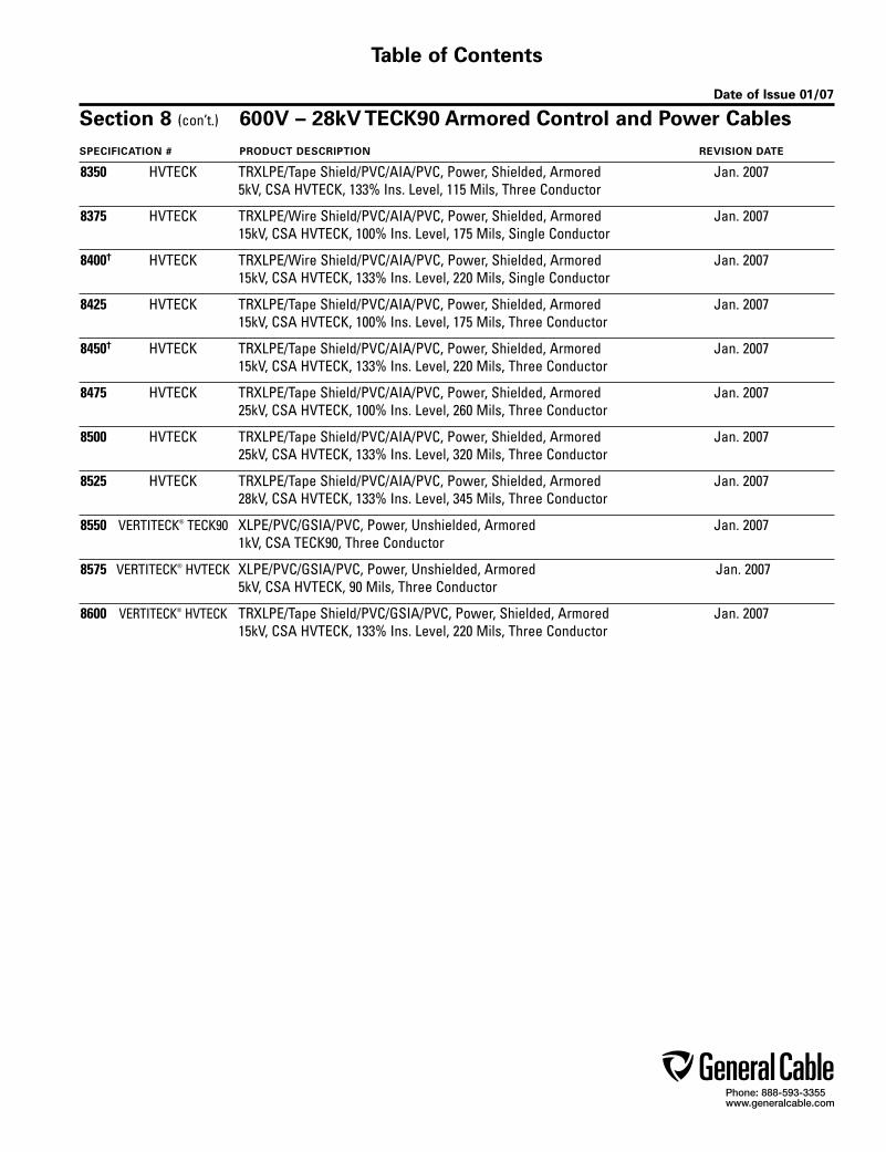
Section 8 (con’t.) 600V – 28kV TECK90 Armored Control and Power CablesSPECIFICATION # PRODUCT DESCRIPTION REVISION DATE
8350 HVTECK TRXLPE/Tape Shield/PVC/AIA/PVC, Power, Shielded, Armored Jan. 2007 5kV, CSA HVTECK, 133% Ins. Level, 115 Mils, Three Conductor
8375 HVTECK TRXLPE/Wire Shield/PVC/AIA/PVC, Power, Shielded, Armored Jan. 2007 15kV, CSA HVTECK, 100% Ins. Level, 175 Mils, Single Conductor
8400† HVTECK TRXLPE/Wire Shield/PVC/AIA/PVC, Power, Shielded, Armored Jan. 2007 15kV, CSA HVTECK, 133% Ins. Level, 220 Mils, Single Conductor
8425 HVTECK TRXLPE/Tape Shield/PVC/AIA/PVC, Power, Shielded, Armored Jan. 2007 15kV, CSA HVTECK, 100% Ins. Level, 175 Mils, Three Conductor
8450† HVTECK TRXLPE/Tape Shield/PVC/AIA/PVC, Power, Shielded, Armored Jan. 2007 15kV, CSA HVTECK, 133% Ins. Level, 220 Mils, Three Conductor
8475 HVTECK TRXLPE/Tape Shield/PVC/AIA/PVC, Power, Shielded, Armored Jan. 2007 25kV, CSA HVTECK, 100% Ins. Level, 260 Mils, Three Conductor
8500 HVTECK TRXLPE/Tape Shield/PVC/AIA/PVC, Power, Shielded, Armored Jan. 2007 25kV, CSA HVTECK, 133% Ins. Level, 320 Mils, Three Conductor
8525 HVTECK TRXLPE/Tape Shield/PVC/AIA/PVC, Power, Shielded, Armored Jan. 2007 28kV, CSA HVTECK, 133% Ins. Level, 345 Mils, Three Conductor
8550 VERTITECK® TECK90 XLPE/PVC/GSIA/PVC, Power, Unshielded, Armored Jan. 2007 1kV, CSA TECK90, Three Conductor
8575 VERTITECK® HVTECK XLPE/PVC/GSIA/PVC, Power, Unshielded, Armored Jan. 2007 5kV, CSA HVTECK, 90 Mils, Three Conductor
8600 VERTITECK® HVTECK TRXLPE/Tape Shield/PVC/GSIA/PVC, Power, Shielded, Armored Jan. 2007 15kV, CSA HVTECK, 133% Ins. Level, 220 Mils, Three Conductor
Phone: 888-593-3355www.generalcable.com
Table of Contents
Date of Issue 01/07
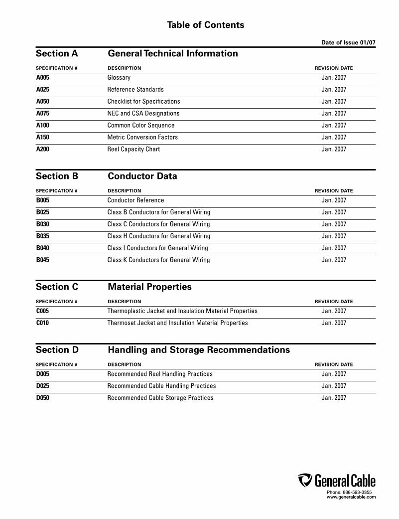
Section A General Technical InformationSPECIFICATION # DESCRIPTION REVISION DATE
A005 Glossary Jan. 2007
A025 Reference Standards Jan. 2007
A050 Checklist for Specifications Jan. 2007
A075 NEC and CSA Designations Jan. 2007
A100 Common Color Sequence Jan. 2007
A150 Metric Conversion Factors Jan. 2007
A200 Reel Capacity Chart Jan. 2007
Section B Conductor DataSPECIFICATION # DESCRIPTION REVISION DATE
B005 Conductor Reference Jan. 2007
B025 Class B Conductors for General Wiring Jan. 2007
B030 Class C Conductors for General Wiring Jan. 2007
B035 Class H Conductors for General Wiring Jan. 2007
B040 Class I Conductors for General Wiring Jan. 2007
B045 Class K Conductors for General Wiring Jan. 2007
Section C Material PropertiesSPECIFICATION # DESCRIPTION REVISION DATE
C005 Thermoplastic Jacket and Insulation Material Properties Jan. 2007
C010 Thermoset Jacket and Insulation Material Properties Jan. 2007
Section D Handling and Storage RecommendationsSPECIFICATION # DESCRIPTION REVISION DATE
D005 Recommended Reel Handling Practices Jan. 2007
D025 Recommended Cable Handling Practices Jan. 2007
D050 Recommended Cable Storage Practices Jan. 2007

Phone: 888-593-3355www.generalcable.com
Table of Contents
Date of Issue 02/07
Section E Cable Installation GuidelinesSPECIFICATION # DESCRIPTION REVISION DATE
E005 Pre-Installation Instructions Jan. 2007
E025 Installation — Overview and Checklist Jan. 2007
E050 Installation — Feed-In Setups Jan. 2007
E075 Installation — Conductor Maximum Pulling Tensions Jan. 2007
E100 Installation — Training and Bending Limitations Jan. 2007
E125 Installation — Maximum Sidewall Pressure Jan. 2007
Section F Cable TestingSPECIFICATION # DESCRIPTION REVISION DATE
F005 DC “Hi Pot” Pre-Test Guidelines for MV Cables Jan. 2007
F025 DC “Hi Pot” Testing Guidelines for MV Cables Jan. 2007
F075 Field Electrical “Hi Pot” Testing Guidelines Jan. 2007
F100 Emergency Overload Current Guidelines Jan. 2007
F125 Short Circuit Current Calculation Overview Jan. 2007
F150 Short Circuit Current for Copper Shields Jan. 2007

Phone: 888-593-3355www.generalcable.com
®
Now one industry leader focuses its worldwide resources on delivering maximum value to customers. It’s the cost-effective advantage of a single resource, a single company that provides the broadest product range, the highest level of commitment to customer and technical support, the most cost-effective manufacturing and distribution, and the most responsive customer-first service. In today’s highly competitive worldwide markets, General Cable provides the single-source solution with benefits that go straight to your bottom line. Ask your representative about other General Cable products.
Energy CablesUnderground High-Voltage and Extra-High-Voltage Cables General Cable’s complete line of Silec® insulated high- and extra-high-voltage underground energy cables, from 63kV up to 500kV, and our state-of-the-art accessories—such as pre-molded joints and terminals—enable us to provide turnkey design and engineer-ing services for the global, systems-engineered, electric utility market.
Bare Overhead High-Voltage Transmission and Distribution Cables Our BICC® Brand cables satisfy the varied and specialized demands of the electrical utility marketplace. Our TransPowr® bare aluminum overhead conductors are available in standard ACSR, specialized T-2 designs and high-temperature ACSS/TW designs. Our new ACCC/TW conductors feature an innovative composite core construction which possess high temperature and increased strength characteristics.
Low- and Medium-Voltage Distribution Cables General Cable’s extensive line of BICC® Brand PowrServ® and EmPowr® copper and aluminum cables serve the total distribution needs of electrical utilities, rural electrical co-ops and the public power market for both traditional and renewable energy resources.
Industrial & Specialty CablesCord and Cordset Products General Cable’s Carol® Brand is the most recognized name in flexible cords for temporary power. Our extensive line includes portable cord, cordsets, portable power cable and premium-grade cable for commercial and industrial applications.
Electronic Cables Our Carol® and Helix/HiTemp® Brand products fulfill the complete wire and cable requirements of the fast-changing electronics, sound and security marketplaces. We offer hookup wire; communications cable; computer, coaxial and microphone cables; and special designs for security systems, fire alarms, and audio, video and digital broadcasts.
Industrial Cables General Cable’s industrial instrumentation, power and control cables serve an extensive range of markets including power generation, refining and petrochemical, natural gas production, steel, pulp and paper, and factory automation.
Specialty Cables General Cable manufactures a broad range of specialty cables that meet the exacting specifications for original equipment manufacturers (OEMs), military, transit, offshore and marine shipboard, nuclear, and mining applications. General Cable’s engineered Brand Rex and Anaconda® Brand wire and cable solutions provide great lifecycle performance and reliability—meeting customer applications requirements today, while setting tomorrow’s standards.
Specialty Wire Harnesses We supply application-specific and custom-designed cable, harnesses and assemblies for a wide variety of OEM applications, including business machines, material handling equipment, factory automation, medical equipment and the automotive aftermarket. General Cable is a global leader in the manufacturer of automotive wire and cable—from ignition wire sets and single leads to bulk ignition wire, primary wire and battery starter cable.
Communications CablesData Communications Cables Our GenSPEED® Brand products are on the job wherever enhanced performance is critical–from Gigabit Ethernet, token ring and broadband applications to patch panels, communications closets and plenum applications. We offer one of the most comprehen-sive lines of enhanced high-speed Category products, including PanGen™ structured cabling system solutions.
Fiber Optic Cables We provide a full menu of NextGen® Brand fiber optic cables for data communications and voice and video networks. Our products range from tight buffer and armored products for military applications to loose tube and hybrid cables for communications networks. We also offer advanced Blolite™ blown fiber systems for Local Area Networks and campus applications.
Telecommunications Cables Our broad range of industry-standard General Cable outside plant wire and cable products ensures reliable, cost-effective performance. We provide air core, filled core and specialty wire products for aerial, buried and duct applications.

Phone: 888-593-3355www.generalcable.com
Date of Issue 01/07Industrial Cables Section 1
300V Instrumentation Cables
SPECIFICATION # PRODUCT DESCRIPTION REVISION DATE
1050 CHTC® XLPE/HYP, Instrumentation, Shielded Jan. 2007 300V, UL Type PLTC, Overall Shielded Pairs/Triads
1100 CHTC® XLPE/HYP, Instrumentation, Shielded Jan. 2007 300V, UL Type PLTC, Individual and Overall Shielded Pairs
1150 CVTC® XLPE/PVC, Instrumentation, Shielded Jan. 2007 300V, UL Type PLTC, Overall Shielded Pairs/Triads
1200 CVTC® XLPE/PVC, Instrumentation, Shielded Jan. 2007 300V, UL Type PLTC, Individual and Overall Shielded Pairs
1250 PVIC® PVC/PVC, Instrumentation, Shielded Jan. 2007 300V, UL Type PLTC/ITC, Overall Shielded Pairs/Triads
1300 PVIC® PVC/PVC, Instrumentation, Shielded Jan. 2007 300V, UL Type PLTC/ITC, Individual and Overall Shielded Pairs
1350 PVIC® PVC/PVC, Instrumentation, Shielded Jan. 2007 300V, UL Type PLTC/ITC, Individual and Overall Shielded Triads

Phone: 888-593-3355www.generalcable.com
SPEC 1050January, 2007
1 20 7/.0121 0.012 0.30 0.035 0.89 0.230 5.84 9 14 27 40
1 TRI 20 7/.0121 0.012 0.30 0.035 0.89 0.240 6.10 13 19 33 49
2 20 7/.0121 0.012 0.30 0.040 1.02 0.320 8.13 17 25 48 71
4 20 7/.0121 0.012 0.30 0.040 1.02 0.370 9.40 31 47 73 109
8 20 7/.0121 0.012 0.30 0.050 1.27 0.500 12.70 60 90 138 205
12 20 7/.0121 0.012 0.30 0.050 1.27 0.575 14.61 89 133 186 277
16 20 7/.0121 0.012 0.30 0.060 1.52 0.665 16.89 118 176 248 369
20 20 7/.0121 0.012 0.30 0.060 1.52 0.740 18.80 148 220 300 446
24 20 7/.0121 0.012 0.30 0.060 1.52 0.795 20.19 177 263 350 521
36 20 7/.0121 0.012 0.30 0.070 1.78 1.005 25.53 264 392 525 781
50 20 7/.0121 0.012 0.30 0.070 1.78 1.175 29.85 365 544 697 1037
337770*337780*337790*309660*309670*309680*337800*337810*309690*311640*309700*
OVERALL SHIELDED PAIRS/TRIADS18 AWG CONDUCTORS
20 AWG CONDUCTORSOVERALL SHIELDED PAIRS/TRIADS
1 18 7/.0152 0.015 0.38 0.035 0.89 0.245 6.22 13 19 32 48
1 TRI 18 7/.0152 0.015 0.38 0.035 0.89 0.255 6.48 18 26 40 60
2 18 7/.0152 0.015 0.38 0.040 1.02 0.350 8.89 23 34 58 86
4 18 7/.0152 0.015 0.38 0.050 1.27 0.425 10.80 44 65 99 147
8 18 7/.0152 0.015 0.38 0.050 1.27 0.545 13.84 86 127 173 257
12 18 7/.0152 0.015 0.38 0.060 1.52 0.640 16.26 127 189 245 365
16 18 7/.0152 0.015 0.38 0.060 1.52 0.730 18.54 169 251 318 473
20 18 7/.0152 0.015 0.38 0.060 1.52 0.810 20.57 210 313 392 583
24 18 7/.0152 0.015 0.38 0.070 1.78 0.895 22.73 252 375 450 670
36 18 7/.0152 0.015 0.38 0.070 1.78 1.095 27.81 377 561 672 1000
50 18 7/.0152 0.015 0.38 0.070 1.78 1.255 31.88 523 778 904 1345
337820*337830*337840*337850*337860*337870*337880*337890*337900*337910*337920*
CATALOG NUMBER
NO. OF PAIRS/TRIADS
MINIMUM AVG. INSULATION THICKNESS
INCHES mm
MINIMUM AVG. JACKET
THICKNESS INCHES mm
NOMINAL CABLE O.D.
INCHES mm
COND.STRAND
COPPER WEIGHT
lbs/ 1000ft kg/km
NET WEIGHT
lbs/ 1000ft kg/km
COND.SIZE
(AWG)
Product ConstructionConductor:
• 20 AWG thru 16 AWG tinned, annealed copper per ASTM B33
• Class B stranding per ASTM B8
Insulation:• Flame-retardant Cross-Linked Polyethylene (XLPE)• Color-coded: per ICEA Method 1; Pairs - black and
white. Triads - black, white and red. One conductor in each pair or triad is printed alpha-numerically for easy identification
Shield:Overall shielded pairs/triads• Overall shield is Flexfoil® aluminum/polyester in
contact with stranded tinned copper drain wire
Jacket:• Low-lead Hypalon® Chlorosulfonated Polyethylene
(CSPE)/Elastomer blend
Print: • GENERAL CABLE® (WC) CHTC XX/PS/TS XXAWG
XLP/HYP SHIELDED (UL) TYPE PLTC 90˚C SUN RES OIL RES I & II PLUS DAY/MONTH/YEAR OF MFG SEQUENTIAL FOOTAGE MARK
Options:• Bare copper conductor• Class C stranding• Individual and overall shielded pairs/triads• Thermoplastic Low-Smoke, Zero-Halogen (LSZH)
jacket• In accordance with UL subject 2250 as
Instrumentation Tray Cable (ITC)• Other constructions available upon request
Applications: • Typical applications include audio, intercom, control,
energy management and alarm circuits• In free air or raceways in accordance with NEC• Permitted for use in Class I Division 2 industrial
hazardous locations per NEC• In ducts, cable trays or conduit• In accordance with UL subject 13 as Power-Limited
Circuit Cable• In class 3 circuits in accordance with NEC
Features:• Rated at 90˚C• Ripcord applied to all cables with jacket thickness of
60 mils or less• Oil-resistant jacket• Sunlight- and weather-resistant• Excellent electrical, thermal and physical properties• Excellent moisture resistance• Excellent flame resistance• “Heavy duty” rating per ICEA standards• Excellent low temperature cold bend
characteristics • Meets cold bend test at -35˚C
Compliances:Industry Compliances: • UL 13 Type PLTC • UL 1581Flame Tests Compliances: • UL 1581 VW-1 • IEEE 383 • IEEE 1202 • CSA FT-4Other Compliances: • EPA 40 CFR, Part 261 for leachable lead
content per TCLP • OSHA acceptable
Packaging:• Material cut to length and shipped on
non-returnable wood reels
OVERALL SHIELDED PAIRS/TRIADS16 AWG CONDUCTORS
1 16 7/.0192 0.015 0.38 0.035 0.89 0.270 6.86 18 28 41 61
1 TRI 16 7/.0192 0.015 0.38 0.035 0.89 0.285 7.24 27 40 54 80
2 16 7/.0192 0.015 0.38 0.050 1.27 0.430 10.92 36 53 85 126
4 16 7/.0192 0.015 0.38 0.050 1.27 0.490 12.45 69 102 135 201
8 16 7/.0192 0.015 0.38 0.060 1.52 0.650 16.51 135 201 246 366
12 16 7/.0192 0.015 0.38 0.060 1.52 0.755 19.18 202 300 346 515
16 16 7/.0192 0.015 0.38 0.060 1.52 0.845 21.46 268 399 444 661
20 16 7/.0192 0.015 0.38 0.060 1.52 0.900 22.86 335 498 552 821
24 16 7/.0192 0.015 0.38 0.070 1.78 1.020 25.91 401 597 655 975
36 16 7/.0192 0.015 0.38 0.070 1.78 1.225 31.12 601 894 649 966
50 16 7/.0192 0.015 0.38 0.080 2.03 1.415 35.94 834 1241 1308 1947
309520*337930*337940*337950*337960*337970*337980*337990*338000*338010*338020*
CHTC®
XLPE/HYP, Instrumentation, Shielded300V, UL Type PLTC, Overall Shielded Pairs/Triads
Dimensions and weights are nominal; subject to industry tolerances.*Non-stock item, minimum runs apply. Please consult Customer Service for price and delivery.

Phone: 888-593-3355www.generalcable.com
SPEC 1100January, 2007
CATALOG NUMBER
NO. OF PAIRS
MINIMUM AVG. INSULATION THICKNESS
INCHES mm
MINIMUM AVG. JACKET
THICKNESS INCHES mm
NOMINAL CABLE O.D.
INCHES mm
COND.STRAND
COPPER WEIGHT
lbs/ 1000ft kg/km
NET WEIGHT
lbs/ 1000ft kg/km
COND.SIZE
(AWG)
CHTC®
XLPE/HYP, Instrumentation, Shielded300V, UL Type PLTC, Individual and Overall Shielded Pairs
2 20 7/.0121 0.012 0.30 0.040 1.02 0.340 8.64 21 31 54 80
4 20 7/.0121 0.012 0.30 0.050 1.27 0.415 10.54 40 60 93 138
8 20 7/.0121 0.012 0.30 0.050 1.27 0.525 13.34 78 116 157 234
12 20 7/.0121 0.012 0.30 0.060 1.52 0.645 16.38 117 174 233 347
16 20 7/.0121 0.012 0.30 0.060 1.52 0.715 18.16 155 231 294 438
20 20 7/.0121 0.012 0.30 0.060 1.52 0.785 19.94 193 287 357 531
24 20 7/.0121 0.012 0.30 0.070 1.78 0.875 22.23 231 344 422 628
36 20 7/.0121 0.012 0.30 0.070 1.78 1.045 26.54 346 515 620 923
50 20 7/.0121 0.012 0.30 0.070 1.78 1.215 30.86 479 713 828 1232
338030*309540*309550*309560*338040*338050*309570*309580*338060*
2 18 7/.0152 0.015 0.38 0.050 1.27 0.415 10.54 28 41 76 113
4 18 7/.0152 0.015 0.38 0.050 1.27 0.475 12.07 53 79 113 168
8 18 7/.0152 0.015 0.38 0.060 1.52 0.605 15.37 104 155 203 302
12 18 7/.0152 0.015 0.38 0.060 1.52 0.750 19.05 155 231 300 446
16 18 7/.0152 0.015 0.38 0.060 1.52 0.830 21.08 206 307 383 570
20 18 7/.0152 0.015 0.38 0.070 1.78 0.945 24.00 254 378 483 719
24 18 7/.0152 0.015 0.38 0.070 1.78 1.045 26.54 308 459 571 850
36 18 7/.0152 0.015 0.38 0.070 1.78 1.225 31.12 461 687 816 1214
50 18 7/.0152 0.015 0.38 0.080 2.03 1.450 36.83 640 952 1119 1665
338070*338080*338090*338100*338110*338120*338130*338140*338150*
20 AWG CONDUCTORSINDIVIDUAL AND OVERALL SHIELDED PAIRS
INDIVIDUAL AND OVERALL SHIELDED PAIRS18 AWG CONDUCTORS
INDIVIDUAL AND OVERALL SHIELDED PAIRS16 AWG CONDUCTORS
Dimensions and weights are nominal; subject to industry tolerances.*Non-stock item, minimum runs apply. Please consult Customer Service for price and delivery.
2 16 7/.0192 0.015 0.38 0.050 1.27 0.440 11.18 40 60 92 137
4 16 7/.0192 0.015 0.38 0.050 1.27 0.545 13.84 78 116 163 243
8 16 7/.0192 0.015 0.38 0.060 1.52 0.965 24.51 153 228 287 427
12 16 7/.0192 0.015 0.38 0.060 1.52 0.885 22.48 229 341 437 650
16 16 7/.0192 0.015 0.38 0.070 1.78 0.980 24.89 304 453 553 823
20 16 7/.0192 0.015 0.38 0.070 1.78 1.080 27.43 380 566 680 1012
24 16 7/.0192 0.015 0.38 0.070 1.78 1.235 31.37 455 677 800 1191
36 16 7/.0192 0.015 0.38 0.080 2.03 1.405 35.69 662 985 1108 1649
50 16 7/.0192 0.015 0.38 0.080 2.03 1.640 41.66 945 1408 1523 2267
338160*338170*338180*338190*338200*338210*338220*338230*338240*
Product ConstructionConductor:
• 20 AWG thru 16 AWG tinned, annealed copper per ASTM B33
• Class B stranding per ASTM B8
Insulation:• Flame-retardant Cross-Linked Polyethylene (XLPE)• Color-coded: per ICEA Method 1; Pairs - black and white.
One conductor in each pair is printed alpha-numerically for easy identification
Shield:Individual and overall shielded pairs• Individual pairs are 100% shielded with Flexfoil®
aluminum/polyester in contact with stranded tinned copper drain wire
• Overall shield is Flexfoil® aluminum/polyester in contact with stranded tinned copper drain wire
Jacket:• Low-lead Hypalon® Chlorosulfonated Polyethylene (CSPE)/
Elastomer blend
Print: • GENERAL CABLE® (WC) CHTC XX/SPS XX AWG
XLP/HYP SHIELDED (UL) TYPE PLTC 90˚C SUN RES OIL RES I & II DAY/MONTH/YEAR OF MFG SEQUENTIAL FOOTAGE MARK
Options:• Bare copper conductor• Class C stranding• Overall shielded pairs• Thermoplastic Low-Smoke, Zero-Halogen (LSZH) jacket• In accordance with UL subject 2250 as Instrumentation
Tray Cable (ITC)• Other constructions available upon request
Applications: • Typical applications include audio, intercom, control, energy
management and alarm circuits• In free air or raceways in accordance with NEC • Permitted for use in Class I Division 2 industrial
hazardous locations per NEC • In ducts, cable trays or conduit• In accordance with UL subject 13 as Power-Limited Circuit
Cable• In class 3 circuits in accordance with NEC
Features:• Rated at 90˚C• Ripcord applied to all cables with jacket thickness of 60
mils or less• Oil-resistant jacket• Sunlight- and weather-resistant• Excellent electrical, thermal and physical properties• Excellent moisture resistance• Excellent flame resistance • “Heavy duty” rating per ICEA standards• Excellent low temperature cold bend characteristics• Meets cold bend test at -35˚C
Compliances:Industry Compliances: • UL 13 Type PLTC • UL 1581Flame Tests Compliances: • UL 1581 VW-1 • IEEE 383 • IEEE 1202 • CSA FT-4Other Compliances: • EPA 40 CFR, Part 261 for leachable lead
content per TCLP • OSHA acceptable
Packaging:• Material cut to length and shipped on
non-returnable wood reels

Phone: 888-593-3355www.generalcable.com
SPEC 1150January, 2007
18 AWG CONDUCTORS 1 18 7/.0152 0.015 0.38 0.035 0.89 0.235 5.97 13 19 32 48
1 TRI 18 7/.0152 0.015 0.38 0.040 1.02 0.250 6.35 18 27 40 60
2 18 7/.0152 0.015 0.38 0.040 1.02 0.365 9.27 25 37 56 83
4 18 7/.0152 0.015 0.38 0.050 1.27 0.440 11.18 46 68 98 146
8 18 7/.0152 0.015 0.38 0.050 1.27 0.550 13.97 87 129 175 260
12 18 7/.0152 0.015 0.38 0.060 1.52 0.675 17.15 129 192 250 372
16 18 7/.0152 0.015 0.38 0.060 1.52 0.750 19.05 171 254 317 472
20 18 7/.0152 0.015 0.38 0.060 1.52 0.785 19.94 211 314 392 583
24 18 7/.0152 0.015 0.38 0.060 1.52 0.905 22.99 253 377 476 708
36 18 7/.0152 0.015 0.38 0.070 1.78 1.080 27.43 377 561 681 1013
50 18 7/.0152 0.015 0.38 0.070 1.78 1.245 31.62 524 780 913 1359
366140*342930*342940*342950*342960*342970*342980*342990*343000*343010*343020*
Product Construction
Conductor:• 18 AWG and 16 AWG bare, annealed
copper per ASTM B3• Class B stranding per ASTM B8
Insulation:• Flame-retardant Cross-Linked Polyethylene
(XLPE)• Color-coded: per ICEA Method 1; pairs - black
and white. Triads - black, white and red. One conductor in each pair or triad is printed alpha-numerically for easy identification
Shield:Overall shielded pairs/triads• Overall shield is Flexfoil® aluminum/polyester in
contact with stranded tinned copper drain wire
Jacket:• Flame-retardant and sunlight-resistant Polyvinyl
Chloride (PVC)
Print: • GENERAL CABLE® (WC) CVTC XX/PS/TS
XXAWG FR-XLP/PVC SHIELDED (UL) TYPE PLTC 90˚C SUN RES PLUS DAY/MONTH/YEAR OF MFG SEQUENTIAL FOOTAGE MARK
Options:• Tinned copper conductor• Class C stranding• Individual and overall shielded pairs/triads• Ethylene Propylene Rubber (EPR) insulation• In accordance with UL subject 2250 as
Instrumentation Tray Cable (ITC)• Other constructions available upon request
Applications: • In free air and raceways in accordance with
NEC• Typical applications include audio, intercom,
control, energy management and alarm circuits• In ducts, cable trays or conduit• In accordance with UL Subject 13 as Power-
Limited Circuit Cable• In Class 3 circuits in accordance with NEC• Permitted for use in Class I Division 2 industrial
hazardous locations per NEC
Features:• Rated at 90˚C• Ripcord applied to all cables with jacket
thickness of 60 mils or less• Abrasion- and chemical-resistant• Excellent electrical properties• Sunlight- and weather-resistant• Meets cold bend test at -25˚C
Compliances:Industry Compliances: • UL 13 Type PLTC • UL 1581Flame Tests Compliances: • UL 1581 VW-1 • IEEE 383Other Compliances: • EPA 40 CFR, Part 261 for leachable lead
content per TCLP • OSHA acceptable
Packaging:• Material cut to length and shipped on
non-returnable wood reels
OVERALL SHIELDED PAIRS/TRIADS16 AWG CONDUCTORS
1 16 7/.0192 0.015 0.38 0.035 0.89 0.262 6.65 19 28 42 63
1 TRI 16 7/.0192 0.015 0.38 0.040 1.02 0.280 7.11 27 40 53 79
2 16 7/.0192 0.015 0.38 0.050 1.27 0.430 10.92 37 55 81 121
4 16 7/.0192 0.015 0.38 0.050 1.27 0.490 12.45 71 106 131 195
8 16 7/.0192 0.015 0.38 0.060 1.52 0.650 16.51 135 201 254 378
12 16 7/.0192 0.015 0.38 0.060 1.52 0.755 19.18 203 302 350 521
16 16 7/.0192 0.015 0.38 0.060 1.52 0.845 21.46 270 402 451 671
20 16 7/.0192 0.015 0.38 0.070 1.78 0.880 22.35 334 497 545 811
24 16 7/.0192 0.015 0.38 0.070 1.78 1.020 25.91 400 595 657 978
36 16 7/.0192 0.015 0.38 0.070 1.78 1.220 30.99 599 891 956 1423
50 16 7/.0192 0.015 0.38 0.080 2.03 1.405 35.69 831 1237 1322 1967
366150*343030*343040*343050*343060*343070*343080*343090*343100*343110*343120*
OVERALL SHIELDED PAIRS/TRIADS
CATALOG NUMBER
NO. OF PAIRS/TRIADS
MINIMUM AVG. INSULATION THICKNESS
INCHES mm
MINIMUM AVG. JACKET
THICKNESS INCHES mm
NOMINAL CABLE O.D.
INCHES mm
COND.STRAND
COPPER WEIGHT
lbs/ 1000ft kg/km
NET WEIGHT
lbs/ 1000ft kg/km
COND.SIZE
(AWG)
Dimensions and weights are nominal; subject to industry tolerances.*Non-stock item, minimum runs apply. Please consult Customer Service for price and delivery.
CVTC®
XLPE/PVC, Instrumentation, Shielded300V, UL Type PLTC, Overall Shielded Pairs/Triads

Phone: 888-593-3355www.generalcable.com
18 AWG CONDUCTORSINDIVIDUAL AND OVERALL SHIELDED PAIRS
Product Construction
Conductor:• 18 AWG and 16 AWG bare, annealed copper
per ASTM B3• Class B stranding per ASTM B8
Insulation:• Flame-retardant Cross-Linked Polyethylene
(XLPE)• Color-coded: per ICEA Method 1; pairs - black
and white. One conductor in each pair is printed alpha-numerically for easy identification
Shield:Individual and overall shielded pairs• Individual pairs are 100% shielded with
Flexfoil® aluminum/polyester in contact with stranded tinned copper drain wire
• Overall shield is Flexfoil® aluminum/polyester in contact with stranded tinned copper drain wire
Jacket:• Flame-retardant and sunlight-resistant Polyvinyl
Chloride (PVC)
Print: • GENERAL CABLE® (WC) CVTC XX/SPS
XXAWG FR-XLP/PVC SHIELDED (UL) TYPE PLTC 90˚C SUN RES PLUS DAY/MONTH/YEAR OF MFG SEQUENTIAL FOOTAGE MARK
Options:• Tinned copper conductor• Class C stranding• Overall shielded pairs• Ethylene Propylene Rubber (EPR) insulation• In accordance with UL subject 2250 as
Instrumentation Tray Cable (ITC)• Other constructions available upon request
Applications: • In free air and raceways in accordance with
NEC• Typical applications include audio, intercom,
control, energy management and alarm circuits• In ducts, cable trays or conduit• In accordance with UL Subject 13 as Power-
Limited Circuit Cable• In Class 3 circuits in accordance with NEC• Permitted for use in Class I Division 2 industrial
hazardous locations per NEC
Features:• Rated at 90˚C• Ripcord applied to all cables with jacket
thickness of 60 mils or less• Abrasion- and chemical-resistant• Excellent electrical properties• Sunlight- and weather-resistant• Meets cold bend test at -25˚C
Compliances:Industry Compliances: • UL 13 Type PLTC • UL 1581Flame Tests Compliances: • UL 1581 VW-1 • IEEE 383Other Compliances: • EPA 40 CFR, Part 261 for leachable lead
content per TCLP • OSHA acceptable
Packaging:• Material cut to length and shipped on
non-returnable wood reels
INDIVIDUAL AND OVERALL SHIELDED PAIRS16 AWG CONDUCTORS
SPEC 1200January, 2007
2 18 7/.0152 0.015 0.38 0.050 1.27 0.410 10.41 30 45 73 109
4 18 7/.0152 0.015 0.38 0.050 1.27 0.475 12.07 55 82 117 174
8 18 7/.0152 0.015 0.38 0.050 1.27 0.605 15.37 105 156 215 320
12 18 7/.0152 0.015 0.38 0.060 1.52 0.750 19.05 156 232 308 458
16 18 7/.0152 0.015 0.38 0.060 1.52 0.830 21.08 207 308 392 583
20 18 7/.0152 0.015 0.38 0.070 1.78 0.955 24.26 252 375 494 735
24 18 7/.0152 0.015 0.38 0.070 1.78 1.030 26.16 302 449 583 868
36 18 7/.0152 0.015 0.38 0.070 1.78 1.210 30.73 452 673 830 1235
50 18 7/.0152 0.015 0.38 0.080 2.03 1.425 36.20 637 948 1145 1704
343140*343150*343160*343170*343180*343190*343200*343210*343220*
2 16 7/.0192 0.015 0.38 0.050 1.27 0.455 11.56 42 63 96 143
4 16 7/.0192 0.015 0.38 0.050 1.27 0.530 13.46 80 119 160 238
8 16 7/.0192 0.015 0.38 0.060 1.52 0.710 18.03 155 231 293 436
12 16 7/.0192 0.015 0.38 0.060 1.52 0.855 21.72 230 342 425 632
16 16 7/.0192 0.015 0.38 0.070 1.78 0.955 24.26 306 455 563 838
20 16 7/.0192 0.015 0.38 0.070 1.78 1.055 26.80 375 558 664 988
24 16 7/.0192 0.015 0.38 0.070 1.78 1.160 29.46 456 679 780 1161
36 16 7/.0192 0.015 0.38 0.080 2.03 1.380 35.05 674 1003 1137 1692
50 16 7/.0192 0.015 0.38 0.080 2.03 1.580 40.13 945 1406 1518 2259
343240*343250*343260*343270*343280*343290*343300*343310*343320*
CATALOG NUMBER
NO. OF PAIRS
MINIMUM AVG. INSULATION THICKNESS
INCHES mm
MINIMUM AVG. JACKET
THICKNESS INCHES mm
NOMINAL CABLE O.D.
INCHES mm
COND.STRAND
COPPER WEIGHT
lbs/ 1000ft kg/km
NET WEIGHT
lbs/ 1000ft kg/km
COND.SIZE
(AWG)
Dimensions and weights are nominal; subject to industry tolerances.*Non-stock item, minimum runs apply. Please consult Customer Service for price and delivery.
CVTC®
XLPE/PVC, Instrumentation, Shielded300V, UL Type PLTC, Individual and Overall Shielded Pairs

Phone: 888-593-3355www.generalcable.com
SPEC 1250January, 2007
20 AWG CONDUCTORSOVERALL SHIELDED PAIRS/TRIADS
Product Construction
Conductor:• 20 AWG thru 16 AWG bare, annealed
copper per ASTM B3• Class B stranding per ASTM B8
Insulation:• Polyvinyl Chloride (PVC)• Color-coded: per ICEA Method 1; Pairs - black
and white. Triads - black, white and red. One conductor in each pair or triad is printed alpha-numerically for easy identification
Shield:Overall shielded pairs/triads• Overall shield is Flexfoil® aluminum/polyester in
contact with stranded tinned copper drain wire
Jacket:• Sunlight-resistant Polyvinyl Chloride (PVC)
Print:• GENERAL CABLE® (WC) PVIC® XX/PS/TS
XXAWG PVC/PVC SHIELDED (UL) TYPE PLTC OR ITC 105˚C SUN RES MONTH/YEAR OF MFG SEQUENTIAL FOOTAGE MARK
Options:• Tinned copper conductor• Class C stranding• Other constructions available upon request
Applications: • In free air and raceways in accordance with
NEC• Typical applications include audio, intercom,
control, energy management and alarm circuits
• In ducts, cable trays or conduit• In accordance with UL Subject 13 as Power-
Limited Circuit Cable• In Class 3 circuits in accordance with NEC
Article 725• In accordance with UL subject 2250 as
Instrumentation Tray Cable (ITC)• Permitted for use in Class I Division 2 industrial
hazardous locations per NEC Article 501-4(b) for UL Type PLTC/ITC cables
• Per NEC Article 727 for Type PLTC/ITC
Features:• Rated at 105˚C• Good electrical properties• Oil- and sunlight-resistant• Flame-retardant• Good mechanical properties• Meets cold bend test at -25˚C
Compliances:Industry Compliances: • UL Type PLTC/ITCFlame Tests Compliances: • IEEE 383 (70,000 BTU/hr) • UL Subject 13 (70,000 BTU/hr) for PLTC • UL Subject 2250 (70,000 BTU/hr) for ITCOther Compliances: • Meets EPA 40 CFR, Part 261 for leachable
lead content per TCLP method • OSHA acceptable
Packaging:• Material cut to length and shipped on
non-returnable wood reels
1 20 7/.0121 0.012 0.30 0.040 1.02 0.220 5.59 9 13 28 42
1 TRI 20 7/.0121 0.012 0.30 0.040 1.02 0.241 6.12 12 18 34 51
2 20 7/.0121 0.012 0.30 0.040 1.02 0.255 6.48 17 25 41 60
4 20 7/.0121 0.012 0.30 0.042 1.07 0.321 8.15 30 45 65 97
8 20 7/.0121 0.012 0.30 0.050 1.27 0.475 12.07 54 80 104 154
12 20 7/.0121 0.012 0.30 0.050 1.27 0.545 13.84 83 124 195 290
16 20 7/.0121 0.012 0.30 0.050 1.27 0.605 15.37 107 159 248 369
20 20 7/.0121 0.012 0.30 0.060 1.52 0.650 16.51 135 201 309 460
24 20 7/.0121 0.012 0.30 0.060 1.52 0.740 18.80 153 228 376 559
36 20 7/.0121 0.012 0.30 0.060 1.52 0.850 21.59 238 354 530 789
50 20 7/.0121 0.012 0.30 0.070 1.78 0.970 24.64 330 491 713 1061
325900*325910*325920*325940*339620*348090*334630*348100*759610*339650*339660*
OVERALL SHIELDED PAIRS/TRIADS18 AWG CONDUCTORS
1 18 7/.0152 0.015 0.38 0.040 1.02 0.240 6.10 12 18 35 52
1 TRI 18 7/.0152 0.015 0.38 0.040 1.02 0.264 6.71 18 27 44 66
2 18 7/.0152 0.015 0.38 0.042 1.07 0.325 8.26 25 37 55 82
4 18 7/.0152 0.015 0.38 0.042 1.07 0.357 9.07 46 68 90 133
8 18 7/.0152 0.015 0.38 0.060 1.52 0.646 16.41 87 129 192 285
12 18 7/.0152 0.015 0.38 0.060 1.52 0.670 17.02 129 192 293 436
16 18 7/.0152 0.015 0.38 0.060 1.52 0.750 19.05 171 254 374 556
20 18 7/.0152 0.015 0.38 0.060 1.52 0.780 19.81 211 314 449 668
24 18 7/.0152 0.015 0.38 0.070 1.78 0.915 23.24 253 377 564 839
36 18 7/.0152 0.015 0.38 0.070 1.78 1.030 26.16 453 674 787 1171
50 18 7/.0152 0.015 0.38 0.070 1.78 1.180 29.97 524 780 1059 1576
325830*325840*325850*325880*348020*348030*348040*339670*339680*791720*339690*
OVERALL SHIELDED PAIRS/TRIADS16 AWG CONDUCTORS
CATALOG NUMBER
NO. OF PAIRS/TRIADS
MINIMUM AVG. INSULATION THICKNESS
INCHES mm
MINIMUM AVG. JACKET
THICKNESS INCHES mm
NOMINAL CABLE O.D.
INCHES mm
COND.STRAND
COPPER WEIGHT
lbs/ 1000ft kg/km
NET WEIGHT
lbs/ 1000ft kg/km
COND.SIZE
(AWG)
PVIC®
PVC/PVC, Instrumentation, Shielded300V, UL Type PLTC/ITC, Overall Shielded Pairs/Triads
1 16 7/.0192 0.015 0.38 0.040 1.02 0.273 6.93 18 27 45 67
1 TRI 16 7/.0192 0.015 0.38 0.042 1.07 0.297 7.54 27 40 58 86
2 16 7/.0192 0.015 0.38 0.042 1.07 0.344 8.74 37 55 74 109
4 16 7/.0192 0.015 0.38 0.053 1.35 0.481 12.22 71 106 132 197
8 16 7/.0192 0.015 0.38 0.060 1.52 0.726 18.44 135 201 259 385
12 16 7/.0192 0.015 0.38 0.060 1.52 0.755 19.18 203 302 408 607
16 16 7/.0192 0.015 0.38 0.070 1.78 0.845 21.46 270 402 526 783
20 16 7/.0192 0.015 0.38 0.070 1.78 0.905 22.99 334 497 655 975
24 16 7/.0192 0.015 0.38 0.070 1.78 1.030 26.16 400 595 803 1195
36 16 7/.0192 0.015 0.38 0.070 1.78 1.165 29.59 599 891 1122 1670
50 16 7/.0192 0.015 0.38 0.080 2.03 1.355 34.42 831 1237 1544 2298Dimensions and weights are nominal; subject to industry tolerances.*Non-stock item, minimum runs apply. Please consult Customer Service for price and delivery.
325770*325780*325790*325810*339700*298830*760530*339710*339720*339730*339740*

Phone: 888-593-3355www.generalcable.com
SPEC 1300January, 2007
INDIVIDUAL AND OVERALL SHIELDED PAIRS18 AWG CONDUCTORS
2 18 7/.0152 0.015 0.38 0.042 1.07 0.296 7.52 30 45 61 91
4 18 7/.0152 0.015 0.38 0.042 1.07 0.410 10.41 55 82 100 149
8 18 7/.0152 0.015 0.38 0.060 1.52 0.485 12.32 105 156 212 316
12 18 7/.0152 0.015 0.38 0.060 1.52 0.760 19.30 156 232 315 469
16 18 7/.0152 0.015 0.38 0.060 1.52 0.845 21.46 207 308 401 597
20 18 7/.0152 0.015 0.38 0.070 1.78 0.955 24.26 252 375 505 752
24 18 7/.0152 0.015 0.38 0.070 1.78 1.040 26.42 302 449 596 887
36 18 7/.0152 0.015 0.38 0.070 1.78 1.215 30.86 452 673 846 1259
50 18 7/.0152 0.015 0.38 0.080 2.03 1.450 36.83 628 935 1165 1734
INDIVIDUAL AND OVERALL SHIELDED PAIRS16 AWG CONDUCTORS
2 16 7/.0192 0.015 0.38 0.042 1.07 0.346 8.79 42 63 80 119
4 16 7/.0192 0.015 0.38 0.053 1.35 0.506 12.85 80 119 151 225
8 16 7/.0192 0.015 0.38 0.060 1.52 0.665 16.89 155 231 288 429
12 16 7/.0192 0.015 0.38 0.060 1.52 0.855 21.72 230 342 435 647
16 16 7/.0192 0.015 0.38 0.070 1.78 0.970 24.64 306 455 575 856
20 16 7/.0192 0.015 0.38 0.070 1.78 1.080 27.43 375 558 705 1049
24 16 7/.0192 0.015 0.38 0.070 1.78 1.165 29.59 456 679 828 1232
36 16 7/.0192 0.015 0.38 0.080 2.03 1.390 35.31 674 1003 1215 1808
50 16 7/.0192 0.015 0.38 0.090 2.29 1.655 42.04 935 1391 1670 2485
Product Construction
Conductor:• 20 AWG thru 16 AWG bare, annealed
copper per ASTM B3• Class B stranding per ASTM B8
Insulation:• Polyvinyl Chloride (PVC)• Color-coded: per ICEA Method 1; Pairs - black
and white. One conductor in each pair is printed alpha-numerically for easy identification
Shield:Individual and overall shielded pairs• Individual pairs are 100% shielded with
Flexfoil® aluminum/polyester in contact with stranded tinned copper drain wire
• Overall shield is Flexfoil® aluminum/polyester in contact with stranded tinned copper drain wire
Jacket:• Sunlight-resistant Polyvinyl Chloride (PVC)
Print:• GENERAL CABLE® (WC) PVIC XX/SPS XXAWG
PVC/PVC SHIELDED (UL) TYPE PLTC OR ITC 105˚C SUN RES MONTH/YEAR OF MFG SEQUENTIAL FOOTAGE MARK
Options:• Tinned copper conductor• Class C stranding• Other constructions available upon request
Applications: • In free air and raceways in accordance with
NEC• Typical applications include audio, intercom,
control, energy management and alarm circuits• In ducts, cable trays or conduit• In accordance with UL Subject 13 as Power-
Limited Circuit Cable• In Class 3 circuits in accordance with NEC
Article 725• In accordance with UL subject 2250 as
Instrumentation Tray Cable (ITC)• Permitted for use in Class I Division 2 industrial
hazardous locations per NEC Article 501-4(b) for UL Type PLTC/ITC cables
• Per NEC Article 727 for Type PLTC/ITC
Features:• Rated at 105˚C• Good electrical properties• Oil- and sunlight-resistant• Flame-retardant• Good mechanical properties• Meets cold bend test at -25˚C
Compliances:Industry Compliances: • UL Type PLTC/ITCFlame Tests Compliances: • IEEE 383 (70,000 BTU/hr) • UL Subject 13 (70,000 BTU/hr) for PLTC • UL Subject 2250 (70,000 BTU/hr) for ITCOther Compliances: • Meets EPA 40 CFR, Part 261 for leachable
lead content per TCLP method • OSHA acceptable
Packaging:• Material cut to length and shipped on
non-returnable wood reels
20 AWG CONDUCTORSINDIVIDUAL AND OVERALL SHIELDED PAIRS
2 20 7/.0121 0.012 0.30 0.040 1.02 0.316 8.03 22 33 46 69
4 20 7/.0121 0.012 0.30 0.042 1.07 0.325 8.26 39 58 76 113
8 20 7/.0121 0.012 0.30 0.050 1.27 0.426 10.82 71 106 148 220
12 20 7/.0121 0.012 0.30 0.060 1.52 0.640 16.26 83 124 223 332
16 20 7/.0121 0.012 0.30 0.060 1.52 0.705 17.91 165 246 280 417
20 20 7/.0121 0.012 0.30 0.060 1.52 0.780 19.81 175 260 339 504
24 20 7/.0121 0.012 0.30 0.060 1.52 0.845 21.46 209 311 397 591
36 20 7/.0121 0.012 0.30 0.070 1.78 1.015 25.78 324 482 586 872
50 20 7/.0121 0.012 0.30 0.070 1.78 1.190 30.23 433 644 786 1170
325930*325950*339750*339760*348110*339770*339780*348120*341790*
CATALOG NUMBER
NO. OF PAIRS
MINIMUM AVG. INSULATION THICKNESS
INCHES mm
MINIMUM AVG. JACKET
THICKNESS INCHES mm
NOMINAL CABLE O.D.
INCHES mm
COND.STRAND
COPPER WEIGHT
lbs/ 1000ft kg/km
NET WEIGHT
lbs/ 1000ft kg/km
COND.SIZE
(AWG)
Dimensions and weights are nominal; subject to industry tolerances.*Non-stock item, minimum runs apply. Please consult Customer Service for price and delivery.
PVIC®
PVC/PVC, Instrumentation, Shielded300V, UL Type PLTC/ITC, Individual and Overall Shielded Pairs
325860*325890*348060*348070*760420*339800*339810*339820*339830*
325800*325820*298880*298890*759770*339840*759780*339850*339860*
Phone: 888-593-3355www.generalcable.com
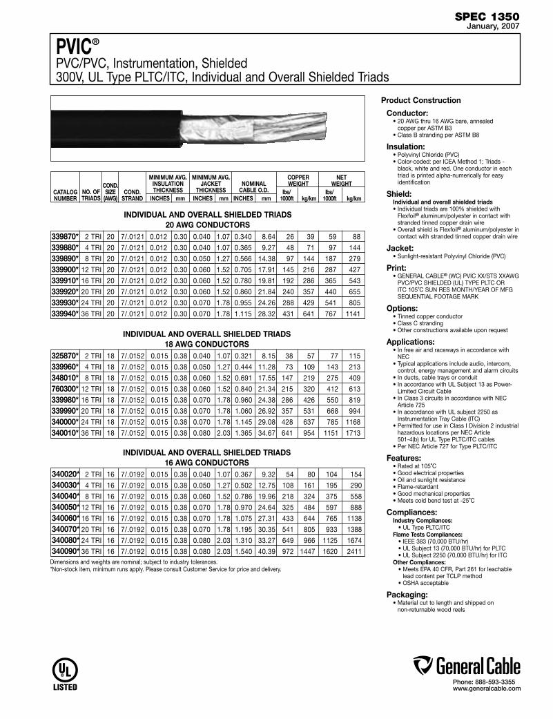
SPEC 1350January, 2007
Product Construction
Conductor:• 20 AWG thru 16 AWG bare, annealed
copper per ASTM B3• Class B stranding per ASTM B8
Insulation:• Polyvinyl Chloride (PVC)• Color-coded: per ICEA Method 1; Triads -
black, white and red. One conductor in each triad is printed alpha-numerically for easy identification
Shield:Individual and overall shielded triads• Individual triads are 100% shielded with
Flexfoil® aluminum/polyester in contact with stranded tinned copper drain wire
• Overall shield is Flexfoil® aluminum/polyester in contact with stranded tinned copper drain wire
Jacket:• Sunlight-resistant Polyvinyl Chloride (PVC)
Print:• GENERAL CABLE® (WC) PVIC XX/STS XXAWG
PVC/PVC SHIELDED (UL) TYPE PLTC OR ITC 105˚C SUN RES MONTH/YEAR OF MFG SEQUENTIAL FOOTAGE MARK
Options:• Tinned copper conductor• Class C stranding• Other constructions available upon request
Applications: • In free air and raceways in accordance with
NEC• Typical applications include audio, intercom,
control, energy management and alarm circuits• In ducts, cable trays or conduit• In accordance with UL Subject 13 as Power-
Limited Circuit Cable• In Class 3 circuits in accordance with NEC
Article 725• In accordance with UL subject 2250 as
Instrumentation Tray Cable (ITC)• Permitted for use in Class I Division 2 industrial
hazardous locations per NEC Article 501-4(b) for UL Type PLTC/ITC cables
• Per NEC Article 727 for Type PLTC/ITC
Features:• Rated at 105˚C• Good electrical properties• Oil and sunlight resistance• Flame-retardant• Good mechanical properties• Meets cold bend test at -25˚C
Compliances:Industry Compliances: • UL Type PLTC/ITCFlame Tests Compliances: • IEEE 383 (70,000 BTU/hr) • UL Subject 13 (70,000 BTU/hr) for PLTC • UL Subject 2250 (70,000 BTU/hr) for ITCOther Compliances: • Meets EPA 40 CFR, Part 261 for leachable
lead content per TCLP method • OSHA acceptable
Packaging:• Material cut to length and shipped on
non-returnable wood reels
2 TRI 20 7/.0121 0.012 0.30 0.040 1.07 0.340 8.64 26 39 59 88
4 TRI 20 7/.0121 0.012 0.30 0.040 1.07 0.365 9.27 48 71 97 144
8 TRI 20 7/.0121 0.012 0.30 0.050 1.27 0.566 14.38 97 144 187 279
12 TRI 20 7/.0121 0.012 0.30 0.060 1.52 0.705 17.91 145 216 287 427
16 TRI 20 7/.0121 0.012 0.30 0.060 1.52 0.780 19.81 192 286 365 543
20 TRI 20 7/.0121 0.012 0.30 0.060 1.52 0.860 21.84 240 357 440 655
24 TRI 20 7/.0121 0.012 0.30 0.070 1.78 0.955 24.26 288 429 541 805
36 TRI 20 7/.0121 0.012 0.30 0.070 1.78 1.115 28.32 431 641 767 1141
339870*339880*339890*339900*339910*339920*339930*339940*
INDIVIDUAL AND OVERALL SHIELDED TRIADS18 AWG CONDUCTORS
20 AWG CONDUCTORS
2 TRI 18 7/.0152 0.015 0.38 0.040 1.07 0.321 8.15 38 57 77 115
4 TRI 18 7/.0152 0.015 0.38 0.050 1.27 0.444 11.28 73 109 143 213
8 TRI 18 7/.0152 0.015 0.38 0.060 1.52 0.691 17.55 147 219 275 409
12 TRI 18 7/.0152 0.015 0.38 0.060 1.52 0.840 21.34 215 320 412 613
16 TRI 18 7/.0152 0.015 0.38 0.070 1.78 0.960 24.38 286 426 550 819
20 TRI 18 7/.0152 0.015 0.38 0.070 1.78 1.060 26.92 357 531 668 994
24 TRI 18 7/.0152 0.015 0.38 0.070 1.78 1.145 29.08 428 637 785 1168
36 TRI 18 7/.0152 0.015 0.38 0.080 2.03 1.365 34.67 641 954 1151 1713
325870*339960*348010*760300*339980*339990*340000*340010*
INDIVIDUAL AND OVERALL SHIELDED TRIADS16 AWG CONDUCTORS
2 TRI 16 7/.0192 0.015 0.38 0.040 1.07 0.367 9.32 54 80 104 154
4 TRI 16 7/.0192 0.015 0.38 0.050 1.27 0.502 12.75 108 161 195 290
8 TRI 16 7/.0192 0.015 0.38 0.060 1.52 0.786 19.96 218 324 375 558
12 TRI 16 7/.0192 0.015 0.38 0.070 1.78 0.970 24.64 325 484 597 888
16 TRI 16 7/.0192 0.015 0.38 0.070 1.78 1.075 27.31 433 644 765 1138
20 TRI 16 7/.0192 0.015 0.38 0.070 1.78 1.195 30.35 541 805 933 1388
24 TRI 16 7/.0192 0.015 0.38 0.080 2.03 1.310 33.27 649 966 1125 1674
36 TRI 16 7/.0192 0.015 0.38 0.080 2.03 1.540 40.39 972 1447 1620 2411
INDIVIDUAL AND OVERALL SHIELDED TRIADS
CATALOG NUMBER
NO. OF TRIADS
MINIMUM AVG. INSULATION THICKNESS
INCHES mm
MINIMUM AVG. JACKET
THICKNESS INCHES mm
NOMINAL CABLE O.D.
INCHES mm
COND.STRAND
COPPER WEIGHT
lbs/ 1000ft kg/km
NET WEIGHT
lbs/ 1000ft kg/km
COND.SIZE
(AWG)
Dimensions and weights are nominal; subject to industry tolerances.*Non-stock item, minimum runs apply. Please consult Customer Service for price and delivery.
PVIC®
PVC/PVC, Instrumentation, Shielded300V, UL Type PLTC/ITC, Individual and Overall Shielded Triads
340020*340030*340040*340050*340060*340070*340080*340090*

Phone: 888-593-3355www.generalcable.com
Date of Issue 01/07Industrial Cables Section 1
300V Instrumentation Cables
SPECIFICATION # PRODUCT DESCRIPTION REVISION DATE
1050 CHTC® XLPE/HYP, Instrumentation, Shielded Jan. 2007 300V, UL Type PLTC, Overall Shielded Pairs/Triads
1100 CHTC® XLPE/HYP, Instrumentation, Shielded Jan. 2007 300V, UL Type PLTC, Individual and Overall Shielded Pairs
1150 CVTC® XLPE/PVC, Instrumentation, Shielded Jan. 2007 300V, UL Type PLTC, Overall Shielded Pairs/Triads
1200 CVTC® XLPE/PVC, Instrumentation, Shielded Jan. 2007 300V, UL Type PLTC, Individual and Overall Shielded Pairs
1250 PVIC® PVC/PVC, Instrumentation, Shielded Jan. 2007 300V, UL Type PLTC/ITC, Overall Shielded Pairs/Triads
1300 PVIC® PVC/PVC, Instrumentation, Shielded Jan. 2007 300V, UL Type PLTC/ITC, Individual and Overall Shielded Pairs
1350 PVIC® PVC/PVC, Instrumentation, Shielded Jan. 2007 300V, UL Type PLTC/ITC, Individual and Overall Shielded Triads
Phone: 888-593-3355www.generalcable.com
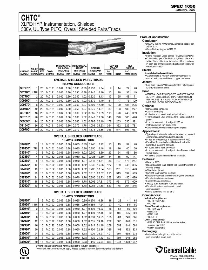
SPEC 1050January, 2007
1 20 7/.0121 0.012 0.30 0.035 0.89 0.230 5.84 9 14 27 40
1 TRI 20 7/.0121 0.012 0.30 0.035 0.89 0.240 6.10 13 19 33 49
2 20 7/.0121 0.012 0.30 0.040 1.02 0.320 8.13 17 25 48 71
4 20 7/.0121 0.012 0.30 0.040 1.02 0.370 9.40 31 47 73 109
8 20 7/.0121 0.012 0.30 0.050 1.27 0.500 12.70 60 90 138 205
12 20 7/.0121 0.012 0.30 0.050 1.27 0.575 14.61 89 133 186 277
16 20 7/.0121 0.012 0.30 0.060 1.52 0.665 16.89 118 176 248 369
20 20 7/.0121 0.012 0.30 0.060 1.52 0.740 18.80 148 220 300 446
24 20 7/.0121 0.012 0.30 0.060 1.52 0.795 20.19 177 263 350 521
36 20 7/.0121 0.012 0.30 0.070 1.78 1.005 25.53 264 392 525 781
50 20 7/.0121 0.012 0.30 0.070 1.78 1.175 29.85 365 544 697 1037
337770*337780*337790*309660*309670*309680*337800*337810*309690*311640*309700*
OVERALL SHIELDED PAIRS/TRIADS18 AWG CONDUCTORS
20 AWG CONDUCTORSOVERALL SHIELDED PAIRS/TRIADS
1 18 7/.0152 0.015 0.38 0.035 0.89 0.245 6.22 13 19 32 48
1 TRI 18 7/.0152 0.015 0.38 0.035 0.89 0.255 6.48 18 26 40 60
2 18 7/.0152 0.015 0.38 0.040 1.02 0.350 8.89 23 34 58 86
4 18 7/.0152 0.015 0.38 0.050 1.27 0.425 10.80 44 65 99 147
8 18 7/.0152 0.015 0.38 0.050 1.27 0.545 13.84 86 127 173 257
12 18 7/.0152 0.015 0.38 0.060 1.52 0.640 16.26 127 189 245 365
16 18 7/.0152 0.015 0.38 0.060 1.52 0.730 18.54 169 251 318 473
20 18 7/.0152 0.015 0.38 0.060 1.52 0.810 20.57 210 313 392 583
24 18 7/.0152 0.015 0.38 0.070 1.78 0.895 22.73 252 375 450 670
36 18 7/.0152 0.015 0.38 0.070 1.78 1.095 27.81 377 561 672 1000
50 18 7/.0152 0.015 0.38 0.070 1.78 1.255 31.88 523 778 904 1345
337820*337830*337840*337850*337860*337870*337880*337890*337900*337910*337920*
CATALOG NUMBER
NO. OF PAIRS/TRIADS
MINIMUM AVG. INSULATION THICKNESS
INCHES mm
MINIMUM AVG. JACKET
THICKNESS INCHES mm
NOMINAL CABLE O.D.
INCHES mm
COND.STRAND
COPPER WEIGHT
lbs/ 1000ft kg/km
NET WEIGHT
lbs/ 1000ft kg/km
COND.SIZE
(AWG)
Product ConstructionConductor:
• 20 AWG thru 16 AWG tinned, annealed copper per ASTM B33
• Class B stranding per ASTM B8
Insulation:• Flame-retardant Cross-Linked Polyethylene (XLPE)• Color-coded: per ICEA Method 1; Pairs - black and
white. Triads - black, white and red. One conductor in each pair or triad is printed alpha-numerically for easy identification
Shield:Overall shielded pairs/triads• Overall shield is Flexfoil® aluminum/polyester in
contact with stranded tinned copper drain wire
Jacket:• Low-lead Hypalon® Chlorosulfonated Polyethylene
(CSPE)/Elastomer blend
Print: • GENERAL CABLE® (WC) CHTC XX/PS/TS XXAWG
XLP/HYP SHIELDED (UL) TYPE PLTC 90˚C SUN RES OIL RES I & II PLUS DAY/MONTH/YEAR OF MFG SEQUENTIAL FOOTAGE MARK
Options:• Bare copper conductor• Class C stranding• Individual and overall shielded pairs/triads• Thermoplastic Low-Smoke, Zero-Halogen (LSZH)
jacket• In accordance with UL subject 2250 as
Instrumentation Tray Cable (ITC)• Other constructions available upon request
Applications: • Typical applications include audio, intercom, control,
energy management and alarm circuits• In free air or raceways in accordance with NEC• Permitted for use in Class I Division 2 industrial
hazardous locations per NEC• In ducts, cable trays or conduit• In accordance with UL subject 13 as Power-Limited
Circuit Cable• In class 3 circuits in accordance with NEC
Features:• Rated at 90˚C• Ripcord applied to all cables with jacket thickness of
60 mils or less• Oil-resistant jacket• Sunlight- and weather-resistant• Excellent electrical, thermal and physical properties• Excellent moisture resistance• Excellent flame resistance• “Heavy duty” rating per ICEA standards• Excellent low temperature cold bend
characteristics • Meets cold bend test at -35˚C
Compliances:Industry Compliances: • UL 13 Type PLTC • UL 1581Flame Tests Compliances: • UL 1581 VW-1 • IEEE 383 • IEEE 1202 • CSA FT-4Other Compliances: • EPA 40 CFR, Part 261 for leachable lead
content per TCLP • OSHA acceptable
Packaging:• Material cut to length and shipped on
non-returnable wood reels
OVERALL SHIELDED PAIRS/TRIADS16 AWG CONDUCTORS
1 16 7/.0192 0.015 0.38 0.035 0.89 0.270 6.86 18 28 41 61
1 TRI 16 7/.0192 0.015 0.38 0.035 0.89 0.285 7.24 27 40 54 80
2 16 7/.0192 0.015 0.38 0.050 1.27 0.430 10.92 36 53 85 126
4 16 7/.0192 0.015 0.38 0.050 1.27 0.490 12.45 69 102 135 201
8 16 7/.0192 0.015 0.38 0.060 1.52 0.650 16.51 135 201 246 366
12 16 7/.0192 0.015 0.38 0.060 1.52 0.755 19.18 202 300 346 515
16 16 7/.0192 0.015 0.38 0.060 1.52 0.845 21.46 268 399 444 661
20 16 7/.0192 0.015 0.38 0.060 1.52 0.900 22.86 335 498 552 821
24 16 7/.0192 0.015 0.38 0.070 1.78 1.020 25.91 401 597 655 975
36 16 7/.0192 0.015 0.38 0.070 1.78 1.225 31.12 601 894 649 966
50 16 7/.0192 0.015 0.38 0.080 2.03 1.415 35.94 834 1241 1308 1947
309520*337930*337940*337950*337960*337970*337980*337990*338000*338010*338020*
CHTC®
XLPE/HYP, Instrumentation, Shielded300V, UL Type PLTC, Overall Shielded Pairs/Triads
Dimensions and weights are nominal; subject to industry tolerances.*Non-stock item, minimum runs apply. Please consult Customer Service for price and delivery.

Phone: 888-593-3355www.generalcable.com
SPEC 1100January, 2007
CATALOG NUMBER
NO. OF PAIRS
MINIMUM AVG. INSULATION THICKNESS
INCHES mm
MINIMUM AVG. JACKET
THICKNESS INCHES mm
NOMINAL CABLE O.D.
INCHES mm
COND.STRAND
COPPER WEIGHT
lbs/ 1000ft kg/km
NET WEIGHT
lbs/ 1000ft kg/km
COND.SIZE
(AWG)
CHTC®
XLPE/HYP, Instrumentation, Shielded300V, UL Type PLTC, Individual and Overall Shielded Pairs
2 20 7/.0121 0.012 0.30 0.040 1.02 0.340 8.64 21 31 54 80
4 20 7/.0121 0.012 0.30 0.050 1.27 0.415 10.54 40 60 93 138
8 20 7/.0121 0.012 0.30 0.050 1.27 0.525 13.34 78 116 157 234
12 20 7/.0121 0.012 0.30 0.060 1.52 0.645 16.38 117 174 233 347
16 20 7/.0121 0.012 0.30 0.060 1.52 0.715 18.16 155 231 294 438
20 20 7/.0121 0.012 0.30 0.060 1.52 0.785 19.94 193 287 357 531
24 20 7/.0121 0.012 0.30 0.070 1.78 0.875 22.23 231 344 422 628
36 20 7/.0121 0.012 0.30 0.070 1.78 1.045 26.54 346 515 620 923
50 20 7/.0121 0.012 0.30 0.070 1.78 1.215 30.86 479 713 828 1232
338030*309540*309550*309560*338040*338050*309570*309580*338060*
2 18 7/.0152 0.015 0.38 0.050 1.27 0.415 10.54 28 41 76 113
4 18 7/.0152 0.015 0.38 0.050 1.27 0.475 12.07 53 79 113 168
8 18 7/.0152 0.015 0.38 0.060 1.52 0.605 15.37 104 155 203 302
12 18 7/.0152 0.015 0.38 0.060 1.52 0.750 19.05 155 231 300 446
16 18 7/.0152 0.015 0.38 0.060 1.52 0.830 21.08 206 307 383 570
20 18 7/.0152 0.015 0.38 0.070 1.78 0.945 24.00 254 378 483 719
24 18 7/.0152 0.015 0.38 0.070 1.78 1.045 26.54 308 459 571 850
36 18 7/.0152 0.015 0.38 0.070 1.78 1.225 31.12 461 687 816 1214
50 18 7/.0152 0.015 0.38 0.080 2.03 1.450 36.83 640 952 1119 1665
338070*338080*338090*338100*338110*338120*338130*338140*338150*
20 AWG CONDUCTORSINDIVIDUAL AND OVERALL SHIELDED PAIRS
INDIVIDUAL AND OVERALL SHIELDED PAIRS18 AWG CONDUCTORS
INDIVIDUAL AND OVERALL SHIELDED PAIRS16 AWG CONDUCTORS
Dimensions and weights are nominal; subject to industry tolerances.*Non-stock item, minimum runs apply. Please consult Customer Service for price and delivery.
2 16 7/.0192 0.015 0.38 0.050 1.27 0.440 11.18 40 60 92 137
4 16 7/.0192 0.015 0.38 0.050 1.27 0.545 13.84 78 116 163 243
8 16 7/.0192 0.015 0.38 0.060 1.52 0.965 24.51 153 228 287 427
12 16 7/.0192 0.015 0.38 0.060 1.52 0.885 22.48 229 341 437 650
16 16 7/.0192 0.015 0.38 0.070 1.78 0.980 24.89 304 453 553 823
20 16 7/.0192 0.015 0.38 0.070 1.78 1.080 27.43 380 566 680 1012
24 16 7/.0192 0.015 0.38 0.070 1.78 1.235 31.37 455 677 800 1191
36 16 7/.0192 0.015 0.38 0.080 2.03 1.405 35.69 662 985 1108 1649
50 16 7/.0192 0.015 0.38 0.080 2.03 1.640 41.66 945 1408 1523 2267
338160*338170*338180*338190*338200*338210*338220*338230*338240*
Product ConstructionConductor:
• 20 AWG thru 16 AWG tinned, annealed copper per ASTM B33
• Class B stranding per ASTM B8
Insulation:• Flame-retardant Cross-Linked Polyethylene (XLPE)• Color-coded: per ICEA Method 1; Pairs - black and white.
One conductor in each pair is printed alpha-numerically for easy identification
Shield:Individual and overall shielded pairs• Individual pairs are 100% shielded with Flexfoil®
aluminum/polyester in contact with stranded tinned copper drain wire
• Overall shield is Flexfoil® aluminum/polyester in contact with stranded tinned copper drain wire
Jacket:• Low-lead Hypalon® Chlorosulfonated Polyethylene (CSPE)/
Elastomer blend
Print: • GENERAL CABLE® (WC) CHTC XX/SPS XX AWG
XLP/HYP SHIELDED (UL) TYPE PLTC 90˚C SUN RES OIL RES I & II DAY/MONTH/YEAR OF MFG SEQUENTIAL FOOTAGE MARK
Options:• Bare copper conductor• Class C stranding• Overall shielded pairs• Thermoplastic Low-Smoke, Zero-Halogen (LSZH) jacket• In accordance with UL subject 2250 as Instrumentation
Tray Cable (ITC)• Other constructions available upon request
Applications: • Typical applications include audio, intercom, control, energy
management and alarm circuits• In free air or raceways in accordance with NEC • Permitted for use in Class I Division 2 industrial
hazardous locations per NEC • In ducts, cable trays or conduit• In accordance with UL subject 13 as Power-Limited Circuit
Cable• In class 3 circuits in accordance with NEC
Features:• Rated at 90˚C• Ripcord applied to all cables with jacket thickness of 60
mils or less• Oil-resistant jacket• Sunlight- and weather-resistant• Excellent electrical, thermal and physical properties• Excellent moisture resistance• Excellent flame resistance • “Heavy duty” rating per ICEA standards• Excellent low temperature cold bend characteristics• Meets cold bend test at -35˚C
Compliances:Industry Compliances: • UL 13 Type PLTC • UL 1581Flame Tests Compliances: • UL 1581 VW-1 • IEEE 383 • IEEE 1202 • CSA FT-4Other Compliances: • EPA 40 CFR, Part 261 for leachable lead
content per TCLP • OSHA acceptable
Packaging:• Material cut to length and shipped on
non-returnable wood reels
Phone: 888-593-3355www.generalcable.com
SPEC 1150January, 2007
18 AWG CONDUCTORS 1 18 7/.0152 0.015 0.38 0.035 0.89 0.235 5.97 13 19 32 48
1 TRI 18 7/.0152 0.015 0.38 0.040 1.02 0.250 6.35 18 27 40 60
2 18 7/.0152 0.015 0.38 0.040 1.02 0.365 9.27 25 37 56 83
4 18 7/.0152 0.015 0.38 0.050 1.27 0.440 11.18 46 68 98 146
8 18 7/.0152 0.015 0.38 0.050 1.27 0.550 13.97 87 129 175 260
12 18 7/.0152 0.015 0.38 0.060 1.52 0.675 17.15 129 192 250 372
16 18 7/.0152 0.015 0.38 0.060 1.52 0.750 19.05 171 254 317 472
20 18 7/.0152 0.015 0.38 0.060 1.52 0.785 19.94 211 314 392 583
24 18 7/.0152 0.015 0.38 0.060 1.52 0.905 22.99 253 377 476 708
36 18 7/.0152 0.015 0.38 0.070 1.78 1.080 27.43 377 561 681 1013
50 18 7/.0152 0.015 0.38 0.070 1.78 1.245 31.62 524 780 913 1359
366140*342930*342940*342950*342960*342970*342980*342990*343000*343010*343020*
Product Construction
Conductor:• 18 AWG and 16 AWG bare, annealed
copper per ASTM B3• Class B stranding per ASTM B8
Insulation:• Flame-retardant Cross-Linked Polyethylene
(XLPE)• Color-coded: per ICEA Method 1; pairs - black
and white. Triads - black, white and red. One conductor in each pair or triad is printed alpha-numerically for easy identification
Shield:Overall shielded pairs/triads• Overall shield is Flexfoil® aluminum/polyester in
contact with stranded tinned copper drain wire
Jacket:• Flame-retardant and sunlight-resistant Polyvinyl
Chloride (PVC)
Print: • GENERAL CABLE® (WC) CVTC XX/PS/TS
XXAWG FR-XLP/PVC SHIELDED (UL) TYPE PLTC 90˚C SUN RES PLUS DAY/MONTH/YEAR OF MFG SEQUENTIAL FOOTAGE MARK
Options:• Tinned copper conductor• Class C stranding• Individual and overall shielded pairs/triads• Ethylene Propylene Rubber (EPR) insulation• In accordance with UL subject 2250 as
Instrumentation Tray Cable (ITC)• Other constructions available upon request
Applications: • In free air and raceways in accordance with
NEC• Typical applications include audio, intercom,
control, energy management and alarm circuits• In ducts, cable trays or conduit• In accordance with UL Subject 13 as Power-
Limited Circuit Cable• In Class 3 circuits in accordance with NEC• Permitted for use in Class I Division 2 industrial
hazardous locations per NEC
Features:• Rated at 90˚C• Ripcord applied to all cables with jacket
thickness of 60 mils or less• Abrasion- and chemical-resistant• Excellent electrical properties• Sunlight- and weather-resistant• Meets cold bend test at -25˚C
Compliances:Industry Compliances: • UL 13 Type PLTC • UL 1581Flame Tests Compliances: • UL 1581 VW-1 • IEEE 383Other Compliances: • EPA 40 CFR, Part 261 for leachable lead
content per TCLP • OSHA acceptable
Packaging:• Material cut to length and shipped on
non-returnable wood reels
OVERALL SHIELDED PAIRS/TRIADS16 AWG CONDUCTORS
1 16 7/.0192 0.015 0.38 0.035 0.89 0.262 6.65 19 28 42 63
1 TRI 16 7/.0192 0.015 0.38 0.040 1.02 0.280 7.11 27 40 53 79
2 16 7/.0192 0.015 0.38 0.050 1.27 0.430 10.92 37 55 81 121
4 16 7/.0192 0.015 0.38 0.050 1.27 0.490 12.45 71 106 131 195
8 16 7/.0192 0.015 0.38 0.060 1.52 0.650 16.51 135 201 254 378
12 16 7/.0192 0.015 0.38 0.060 1.52 0.755 19.18 203 302 350 521
16 16 7/.0192 0.015 0.38 0.060 1.52 0.845 21.46 270 402 451 671
20 16 7/.0192 0.015 0.38 0.070 1.78 0.880 22.35 334 497 545 811
24 16 7/.0192 0.015 0.38 0.070 1.78 1.020 25.91 400 595 657 978
36 16 7/.0192 0.015 0.38 0.070 1.78 1.220 30.99 599 891 956 1423
50 16 7/.0192 0.015 0.38 0.080 2.03 1.405 35.69 831 1237 1322 1967
366150*343030*343040*343050*343060*343070*343080*343090*343100*343110*343120*
OVERALL SHIELDED PAIRS/TRIADS
CATALOG NUMBER
NO. OF PAIRS/TRIADS
MINIMUM AVG. INSULATION THICKNESS
INCHES mm
MINIMUM AVG. JACKET
THICKNESS INCHES mm
NOMINAL CABLE O.D.
INCHES mm
COND.STRAND
COPPER WEIGHT
lbs/ 1000ft kg/km
NET WEIGHT
lbs/ 1000ft kg/km
COND.SIZE
(AWG)
Dimensions and weights are nominal; subject to industry tolerances.*Non-stock item, minimum runs apply. Please consult Customer Service for price and delivery.
CVTC®
XLPE/PVC, Instrumentation, Shielded300V, UL Type PLTC, Overall Shielded Pairs/Triads
Phone: 888-593-3355www.generalcable.com
18 AWG CONDUCTORSINDIVIDUAL AND OVERALL SHIELDED PAIRS
Product Construction
Conductor:• 18 AWG and 16 AWG bare, annealed copper
per ASTM B3• Class B stranding per ASTM B8
Insulation:• Flame-retardant Cross-Linked Polyethylene
(XLPE)• Color-coded: per ICEA Method 1; pairs - black
and white. One conductor in each pair is printed alpha-numerically for easy identification
Shield:Individual and overall shielded pairs• Individual pairs are 100% shielded with
Flexfoil® aluminum/polyester in contact with stranded tinned copper drain wire
• Overall shield is Flexfoil® aluminum/polyester in contact with stranded tinned copper drain wire
Jacket:• Flame-retardant and sunlight-resistant Polyvinyl
Chloride (PVC)
Print: • GENERAL CABLE® (WC) CVTC XX/SPS
XXAWG FR-XLP/PVC SHIELDED (UL) TYPE PLTC 90˚C SUN RES PLUS DAY/MONTH/YEAR OF MFG SEQUENTIAL FOOTAGE MARK
Options:• Tinned copper conductor• Class C stranding• Overall shielded pairs• Ethylene Propylene Rubber (EPR) insulation• In accordance with UL subject 2250 as
Instrumentation Tray Cable (ITC)• Other constructions available upon request
Applications: • In free air and raceways in accordance with
NEC• Typical applications include audio, intercom,
control, energy management and alarm circuits• In ducts, cable trays or conduit• In accordance with UL Subject 13 as Power-
Limited Circuit Cable• In Class 3 circuits in accordance with NEC• Permitted for use in Class I Division 2 industrial
hazardous locations per NEC
Features:• Rated at 90˚C• Ripcord applied to all cables with jacket
thickness of 60 mils or less• Abrasion- and chemical-resistant• Excellent electrical properties• Sunlight- and weather-resistant• Meets cold bend test at -25˚C
Compliances:Industry Compliances: • UL 13 Type PLTC • UL 1581Flame Tests Compliances: • UL 1581 VW-1 • IEEE 383Other Compliances: • EPA 40 CFR, Part 261 for leachable lead
content per TCLP • OSHA acceptable
Packaging:• Material cut to length and shipped on
non-returnable wood reels
INDIVIDUAL AND OVERALL SHIELDED PAIRS16 AWG CONDUCTORS
SPEC 1200January, 2007
2 18 7/.0152 0.015 0.38 0.050 1.27 0.410 10.41 30 45 73 109
4 18 7/.0152 0.015 0.38 0.050 1.27 0.475 12.07 55 82 117 174
8 18 7/.0152 0.015 0.38 0.050 1.27 0.605 15.37 105 156 215 320
12 18 7/.0152 0.015 0.38 0.060 1.52 0.750 19.05 156 232 308 458
16 18 7/.0152 0.015 0.38 0.060 1.52 0.830 21.08 207 308 392 583
20 18 7/.0152 0.015 0.38 0.070 1.78 0.955 24.26 252 375 494 735
24 18 7/.0152 0.015 0.38 0.070 1.78 1.030 26.16 302 449 583 868
36 18 7/.0152 0.015 0.38 0.070 1.78 1.210 30.73 452 673 830 1235
50 18 7/.0152 0.015 0.38 0.080 2.03 1.425 36.20 637 948 1145 1704
343140*343150*343160*343170*343180*343190*343200*343210*343220*
2 16 7/.0192 0.015 0.38 0.050 1.27 0.455 11.56 42 63 96 143
4 16 7/.0192 0.015 0.38 0.050 1.27 0.530 13.46 80 119 160 238
8 16 7/.0192 0.015 0.38 0.060 1.52 0.710 18.03 155 231 293 436
12 16 7/.0192 0.015 0.38 0.060 1.52 0.855 21.72 230 342 425 632
16 16 7/.0192 0.015 0.38 0.070 1.78 0.955 24.26 306 455 563 838
20 16 7/.0192 0.015 0.38 0.070 1.78 1.055 26.80 375 558 664 988
24 16 7/.0192 0.015 0.38 0.070 1.78 1.160 29.46 456 679 780 1161
36 16 7/.0192 0.015 0.38 0.080 2.03 1.380 35.05 674 1003 1137 1692
50 16 7/.0192 0.015 0.38 0.080 2.03 1.580 40.13 945 1406 1518 2259
343240*343250*343260*343270*343280*343290*343300*343310*343320*
CATALOG NUMBER
NO. OF PAIRS
MINIMUM AVG. INSULATION THICKNESS
INCHES mm
MINIMUM AVG. JACKET
THICKNESS INCHES mm
NOMINAL CABLE O.D.
INCHES mm
COND.STRAND
COPPER WEIGHT
lbs/ 1000ft kg/km
NET WEIGHT
lbs/ 1000ft kg/km
COND.SIZE
(AWG)
Dimensions and weights are nominal; subject to industry tolerances.*Non-stock item, minimum runs apply. Please consult Customer Service for price and delivery.
CVTC®
XLPE/PVC, Instrumentation, Shielded300V, UL Type PLTC, Individual and Overall Shielded Pairs
Phone: 888-593-3355www.generalcable.com
SPEC 1250January, 2007
20 AWG CONDUCTORSOVERALL SHIELDED PAIRS/TRIADS
Product Construction
Conductor:• 20 AWG thru 16 AWG bare, annealed
copper per ASTM B3• Class B stranding per ASTM B8
Insulation:• Polyvinyl Chloride (PVC)• Color-coded: per ICEA Method 1; Pairs - black
and white. Triads - black, white and red. One conductor in each pair or triad is printed alpha-numerically for easy identification
Shield:Overall shielded pairs/triads• Overall shield is Flexfoil® aluminum/polyester in
contact with stranded tinned copper drain wire
Jacket:• Sunlight-resistant Polyvinyl Chloride (PVC)
Print:• GENERAL CABLE® (WC) PVIC® XX/PS/TS
XXAWG PVC/PVC SHIELDED (UL) TYPE PLTC OR ITC 105˚C SUN RES MONTH/YEAR OF MFG SEQUENTIAL FOOTAGE MARK
Options:• Tinned copper conductor• Class C stranding• Other constructions available upon request
Applications: • In free air and raceways in accordance with
NEC• Typical applications include audio, intercom,
control, energy management and alarm circuits
• In ducts, cable trays or conduit• In accordance with UL Subject 13 as Power-
Limited Circuit Cable• In Class 3 circuits in accordance with NEC
Article 725• In accordance with UL subject 2250 as
Instrumentation Tray Cable (ITC)• Permitted for use in Class I Division 2 industrial
hazardous locations per NEC Article 501-4(b) for UL Type PLTC/ITC cables
• Per NEC Article 727 for Type PLTC/ITC
Features:• Rated at 105˚C• Good electrical properties• Oil- and sunlight-resistant• Flame-retardant• Good mechanical properties• Meets cold bend test at -25˚C
Compliances:Industry Compliances: • UL Type PLTC/ITCFlame Tests Compliances: • IEEE 383 (70,000 BTU/hr) • UL Subject 13 (70,000 BTU/hr) for PLTC • UL Subject 2250 (70,000 BTU/hr) for ITCOther Compliances: • Meets EPA 40 CFR, Part 261 for leachable
lead content per TCLP method • OSHA acceptable
Packaging:• Material cut to length and shipped on
non-returnable wood reels
1 20 7/.0121 0.012 0.30 0.040 1.02 0.220 5.59 9 13 28 42
1 TRI 20 7/.0121 0.012 0.30 0.040 1.02 0.241 6.12 12 18 34 51
2 20 7/.0121 0.012 0.30 0.040 1.02 0.255 6.48 17 25 41 60
4 20 7/.0121 0.012 0.30 0.042 1.07 0.321 8.15 30 45 65 97
8 20 7/.0121 0.012 0.30 0.050 1.27 0.475 12.07 54 80 104 154
12 20 7/.0121 0.012 0.30 0.050 1.27 0.545 13.84 83 124 195 290
16 20 7/.0121 0.012 0.30 0.050 1.27 0.605 15.37 107 159 248 369
20 20 7/.0121 0.012 0.30 0.060 1.52 0.650 16.51 135 201 309 460
24 20 7/.0121 0.012 0.30 0.060 1.52 0.740 18.80 153 228 376 559
36 20 7/.0121 0.012 0.30 0.060 1.52 0.850 21.59 238 354 530 789
50 20 7/.0121 0.012 0.30 0.070 1.78 0.970 24.64 330 491 713 1061
325900*325910*325920*325940*339620*348090*334630*348100*759610*339650*339660*
OVERALL SHIELDED PAIRS/TRIADS18 AWG CONDUCTORS
1 18 7/.0152 0.015 0.38 0.040 1.02 0.240 6.10 12 18 35 52
1 TRI 18 7/.0152 0.015 0.38 0.040 1.02 0.264 6.71 18 27 44 66
2 18 7/.0152 0.015 0.38 0.042 1.07 0.325 8.26 25 37 55 82
4 18 7/.0152 0.015 0.38 0.042 1.07 0.357 9.07 46 68 90 133
8 18 7/.0152 0.015 0.38 0.060 1.52 0.646 16.41 87 129 192 285
12 18 7/.0152 0.015 0.38 0.060 1.52 0.670 17.02 129 192 293 436
16 18 7/.0152 0.015 0.38 0.060 1.52 0.750 19.05 171 254 374 556
20 18 7/.0152 0.015 0.38 0.060 1.52 0.780 19.81 211 314 449 668
24 18 7/.0152 0.015 0.38 0.070 1.78 0.915 23.24 253 377 564 839
36 18 7/.0152 0.015 0.38 0.070 1.78 1.030 26.16 453 674 787 1171
50 18 7/.0152 0.015 0.38 0.070 1.78 1.180 29.97 524 780 1059 1576
325830*325840*325850*325880*348020*348030*348040*339670*339680*791720*339690*
OVERALL SHIELDED PAIRS/TRIADS16 AWG CONDUCTORS
CATALOG NUMBER
NO. OF PAIRS/TRIADS
MINIMUM AVG. INSULATION THICKNESS
INCHES mm
MINIMUM AVG. JACKET
THICKNESS INCHES mm
NOMINAL CABLE O.D.
INCHES mm
COND.STRAND
COPPER WEIGHT
lbs/ 1000ft kg/km
NET WEIGHT
lbs/ 1000ft kg/km
COND.SIZE
(AWG)
PVIC®
PVC/PVC, Instrumentation, Shielded300V, UL Type PLTC/ITC, Overall Shielded Pairs/Triads
1 16 7/.0192 0.015 0.38 0.040 1.02 0.273 6.93 18 27 45 67
1 TRI 16 7/.0192 0.015 0.38 0.042 1.07 0.297 7.54 27 40 58 86
2 16 7/.0192 0.015 0.38 0.042 1.07 0.344 8.74 37 55 74 109
4 16 7/.0192 0.015 0.38 0.053 1.35 0.481 12.22 71 106 132 197
8 16 7/.0192 0.015 0.38 0.060 1.52 0.726 18.44 135 201 259 385
12 16 7/.0192 0.015 0.38 0.060 1.52 0.755 19.18 203 302 408 607
16 16 7/.0192 0.015 0.38 0.070 1.78 0.845 21.46 270 402 526 783
20 16 7/.0192 0.015 0.38 0.070 1.78 0.905 22.99 334 497 655 975
24 16 7/.0192 0.015 0.38 0.070 1.78 1.030 26.16 400 595 803 1195
36 16 7/.0192 0.015 0.38 0.070 1.78 1.165 29.59 599 891 1122 1670
50 16 7/.0192 0.015 0.38 0.080 2.03 1.355 34.42 831 1237 1544 2298Dimensions and weights are nominal; subject to industry tolerances.*Non-stock item, minimum runs apply. Please consult Customer Service for price and delivery.
325770*325780*325790*325810*339700*298830*760530*339710*339720*339730*339740*

Phone: 888-593-3355www.generalcable.com
SPEC 1300January, 2007
INDIVIDUAL AND OVERALL SHIELDED PAIRS18 AWG CONDUCTORS
2 18 7/.0152 0.015 0.38 0.042 1.07 0.296 7.52 30 45 61 91
4 18 7/.0152 0.015 0.38 0.042 1.07 0.410 10.41 55 82 100 149
8 18 7/.0152 0.015 0.38 0.060 1.52 0.485 12.32 105 156 212 316
12 18 7/.0152 0.015 0.38 0.060 1.52 0.760 19.30 156 232 315 469
16 18 7/.0152 0.015 0.38 0.060 1.52 0.845 21.46 207 308 401 597
20 18 7/.0152 0.015 0.38 0.070 1.78 0.955 24.26 252 375 505 752
24 18 7/.0152 0.015 0.38 0.070 1.78 1.040 26.42 302 449 596 887
36 18 7/.0152 0.015 0.38 0.070 1.78 1.215 30.86 452 673 846 1259
50 18 7/.0152 0.015 0.38 0.080 2.03 1.450 36.83 628 935 1165 1734
INDIVIDUAL AND OVERALL SHIELDED PAIRS16 AWG CONDUCTORS
2 16 7/.0192 0.015 0.38 0.042 1.07 0.346 8.79 42 63 80 119
4 16 7/.0192 0.015 0.38 0.053 1.35 0.506 12.85 80 119 151 225
8 16 7/.0192 0.015 0.38 0.060 1.52 0.665 16.89 155 231 288 429
12 16 7/.0192 0.015 0.38 0.060 1.52 0.855 21.72 230 342 435 647
16 16 7/.0192 0.015 0.38 0.070 1.78 0.970 24.64 306 455 575 856
20 16 7/.0192 0.015 0.38 0.070 1.78 1.080 27.43 375 558 705 1049
24 16 7/.0192 0.015 0.38 0.070 1.78 1.165 29.59 456 679 828 1232
36 16 7/.0192 0.015 0.38 0.080 2.03 1.390 35.31 674 1003 1215 1808
50 16 7/.0192 0.015 0.38 0.090 2.29 1.655 42.04 935 1391 1670 2485
Product Construction
Conductor:• 20 AWG thru 16 AWG bare, annealed
copper per ASTM B3• Class B stranding per ASTM B8
Insulation:• Polyvinyl Chloride (PVC)• Color-coded: per ICEA Method 1; Pairs - black
and white. One conductor in each pair is printed alpha-numerically for easy identification
Shield:Individual and overall shielded pairs• Individual pairs are 100% shielded with
Flexfoil® aluminum/polyester in contact with stranded tinned copper drain wire
• Overall shield is Flexfoil® aluminum/polyester in contact with stranded tinned copper drain wire
Jacket:• Sunlight-resistant Polyvinyl Chloride (PVC)
Print:• GENERAL CABLE® (WC) PVIC XX/SPS XXAWG
PVC/PVC SHIELDED (UL) TYPE PLTC OR ITC 105˚C SUN RES MONTH/YEAR OF MFG SEQUENTIAL FOOTAGE MARK
Options:• Tinned copper conductor• Class C stranding• Other constructions available upon request
Applications: • In free air and raceways in accordance with
NEC• Typical applications include audio, intercom,
control, energy management and alarm circuits• In ducts, cable trays or conduit• In accordance with UL Subject 13 as Power-
Limited Circuit Cable• In Class 3 circuits in accordance with NEC
Article 725• In accordance with UL subject 2250 as
Instrumentation Tray Cable (ITC)• Permitted for use in Class I Division 2 industrial
hazardous locations per NEC Article 501-4(b) for UL Type PLTC/ITC cables
• Per NEC Article 727 for Type PLTC/ITC
Features:• Rated at 105˚C• Good electrical properties• Oil- and sunlight-resistant• Flame-retardant• Good mechanical properties• Meets cold bend test at -25˚C
Compliances:Industry Compliances: • UL Type PLTC/ITCFlame Tests Compliances: • IEEE 383 (70,000 BTU/hr) • UL Subject 13 (70,000 BTU/hr) for PLTC • UL Subject 2250 (70,000 BTU/hr) for ITCOther Compliances: • Meets EPA 40 CFR, Part 261 for leachable
lead content per TCLP method • OSHA acceptable
Packaging:• Material cut to length and shipped on
non-returnable wood reels
20 AWG CONDUCTORSINDIVIDUAL AND OVERALL SHIELDED PAIRS
2 20 7/.0121 0.012 0.30 0.040 1.02 0.316 8.03 22 33 46 69
4 20 7/.0121 0.012 0.30 0.042 1.07 0.325 8.26 39 58 76 113
8 20 7/.0121 0.012 0.30 0.050 1.27 0.426 10.82 71 106 148 220
12 20 7/.0121 0.012 0.30 0.060 1.52 0.640 16.26 83 124 223 332
16 20 7/.0121 0.012 0.30 0.060 1.52 0.705 17.91 165 246 280 417
20 20 7/.0121 0.012 0.30 0.060 1.52 0.780 19.81 175 260 339 504
24 20 7/.0121 0.012 0.30 0.060 1.52 0.845 21.46 209 311 397 591
36 20 7/.0121 0.012 0.30 0.070 1.78 1.015 25.78 324 482 586 872
50 20 7/.0121 0.012 0.30 0.070 1.78 1.190 30.23 433 644 786 1170
325930*325950*339750*339760*348110*339770*339780*348120*341790*
CATALOG NUMBER
NO. OF PAIRS
MINIMUM AVG. INSULATION THICKNESS
INCHES mm
MINIMUM AVG. JACKET
THICKNESS INCHES mm
NOMINAL CABLE O.D.
INCHES mm
COND.STRAND
COPPER WEIGHT
lbs/ 1000ft kg/km
NET WEIGHT
lbs/ 1000ft kg/km
COND.SIZE
(AWG)
Dimensions and weights are nominal; subject to industry tolerances.*Non-stock item, minimum runs apply. Please consult Customer Service for price and delivery.
PVIC®
PVC/PVC, Instrumentation, Shielded300V, UL Type PLTC/ITC, Individual and Overall Shielded Pairs
325860*325890*348060*348070*760420*339800*339810*339820*339830*
325800*325820*298880*298890*759770*339840*759780*339850*339860*

Phone: 888-593-3355www.generalcable.com
SPEC 1350January, 2007
Product Construction
Conductor:• 20 AWG thru 16 AWG bare, annealed
copper per ASTM B3• Class B stranding per ASTM B8
Insulation:• Polyvinyl Chloride (PVC)• Color-coded: per ICEA Method 1; Triads -
black, white and red. One conductor in each triad is printed alpha-numerically for easy identification
Shield:Individual and overall shielded triads• Individual triads are 100% shielded with
Flexfoil® aluminum/polyester in contact with stranded tinned copper drain wire
• Overall shield is Flexfoil® aluminum/polyester in contact with stranded tinned copper drain wire
Jacket:• Sunlight-resistant Polyvinyl Chloride (PVC)
Print:• GENERAL CABLE® (WC) PVIC XX/STS XXAWG
PVC/PVC SHIELDED (UL) TYPE PLTC OR ITC 105˚C SUN RES MONTH/YEAR OF MFG SEQUENTIAL FOOTAGE MARK
Options:• Tinned copper conductor• Class C stranding• Other constructions available upon request
Applications: • In free air and raceways in accordance with
NEC• Typical applications include audio, intercom,
control, energy management and alarm circuits• In ducts, cable trays or conduit• In accordance with UL Subject 13 as Power-
Limited Circuit Cable• In Class 3 circuits in accordance with NEC
Article 725• In accordance with UL subject 2250 as
Instrumentation Tray Cable (ITC)• Permitted for use in Class I Division 2 industrial
hazardous locations per NEC Article 501-4(b) for UL Type PLTC/ITC cables
• Per NEC Article 727 for Type PLTC/ITC
Features:• Rated at 105˚C• Good electrical properties• Oil and sunlight resistance• Flame-retardant• Good mechanical properties• Meets cold bend test at -25˚C
Compliances:Industry Compliances: • UL Type PLTC/ITCFlame Tests Compliances: • IEEE 383 (70,000 BTU/hr) • UL Subject 13 (70,000 BTU/hr) for PLTC • UL Subject 2250 (70,000 BTU/hr) for ITCOther Compliances: • Meets EPA 40 CFR, Part 261 for leachable
lead content per TCLP method • OSHA acceptable
Packaging:• Material cut to length and shipped on
non-returnable wood reels
2 TRI 20 7/.0121 0.012 0.30 0.040 1.07 0.340 8.64 26 39 59 88
4 TRI 20 7/.0121 0.012 0.30 0.040 1.07 0.365 9.27 48 71 97 144
8 TRI 20 7/.0121 0.012 0.30 0.050 1.27 0.566 14.38 97 144 187 279
12 TRI 20 7/.0121 0.012 0.30 0.060 1.52 0.705 17.91 145 216 287 427
16 TRI 20 7/.0121 0.012 0.30 0.060 1.52 0.780 19.81 192 286 365 543
20 TRI 20 7/.0121 0.012 0.30 0.060 1.52 0.860 21.84 240 357 440 655
24 TRI 20 7/.0121 0.012 0.30 0.070 1.78 0.955 24.26 288 429 541 805
36 TRI 20 7/.0121 0.012 0.30 0.070 1.78 1.115 28.32 431 641 767 1141
339870*339880*339890*339900*339910*339920*339930*339940*
INDIVIDUAL AND OVERALL SHIELDED TRIADS18 AWG CONDUCTORS
20 AWG CONDUCTORS
2 TRI 18 7/.0152 0.015 0.38 0.040 1.07 0.321 8.15 38 57 77 115
4 TRI 18 7/.0152 0.015 0.38 0.050 1.27 0.444 11.28 73 109 143 213
8 TRI 18 7/.0152 0.015 0.38 0.060 1.52 0.691 17.55 147 219 275 409
12 TRI 18 7/.0152 0.015 0.38 0.060 1.52 0.840 21.34 215 320 412 613
16 TRI 18 7/.0152 0.015 0.38 0.070 1.78 0.960 24.38 286 426 550 819
20 TRI 18 7/.0152 0.015 0.38 0.070 1.78 1.060 26.92 357 531 668 994
24 TRI 18 7/.0152 0.015 0.38 0.070 1.78 1.145 29.08 428 637 785 1168
36 TRI 18 7/.0152 0.015 0.38 0.080 2.03 1.365 34.67 641 954 1151 1713
325870*339960*348010*760300*339980*339990*340000*340010*
INDIVIDUAL AND OVERALL SHIELDED TRIADS16 AWG CONDUCTORS
2 TRI 16 7/.0192 0.015 0.38 0.040 1.07 0.367 9.32 54 80 104 154
4 TRI 16 7/.0192 0.015 0.38 0.050 1.27 0.502 12.75 108 161 195 290
8 TRI 16 7/.0192 0.015 0.38 0.060 1.52 0.786 19.96 218 324 375 558
12 TRI 16 7/.0192 0.015 0.38 0.070 1.78 0.970 24.64 325 484 597 888
16 TRI 16 7/.0192 0.015 0.38 0.070 1.78 1.075 27.31 433 644 765 1138
20 TRI 16 7/.0192 0.015 0.38 0.070 1.78 1.195 30.35 541 805 933 1388
24 TRI 16 7/.0192 0.015 0.38 0.080 2.03 1.310 33.27 649 966 1125 1674
36 TRI 16 7/.0192 0.015 0.38 0.080 2.03 1.540 40.39 972 1447 1620 2411
INDIVIDUAL AND OVERALL SHIELDED TRIADS
CATALOG NUMBER
NO. OF TRIADS
MINIMUM AVG. INSULATION THICKNESS
INCHES mm
MINIMUM AVG. JACKET
THICKNESS INCHES mm
NOMINAL CABLE O.D.
INCHES mm
COND.STRAND
COPPER WEIGHT
lbs/ 1000ft kg/km
NET WEIGHT
lbs/ 1000ft kg/km
COND.SIZE
(AWG)
Dimensions and weights are nominal; subject to industry tolerances.*Non-stock item, minimum runs apply. Please consult Customer Service for price and delivery.
PVIC®
PVC/PVC, Instrumentation, Shielded300V, UL Type PLTC/ITC, Individual and Overall Shielded Triads
340020*340030*340040*340050*340060*340070*340080*340090*
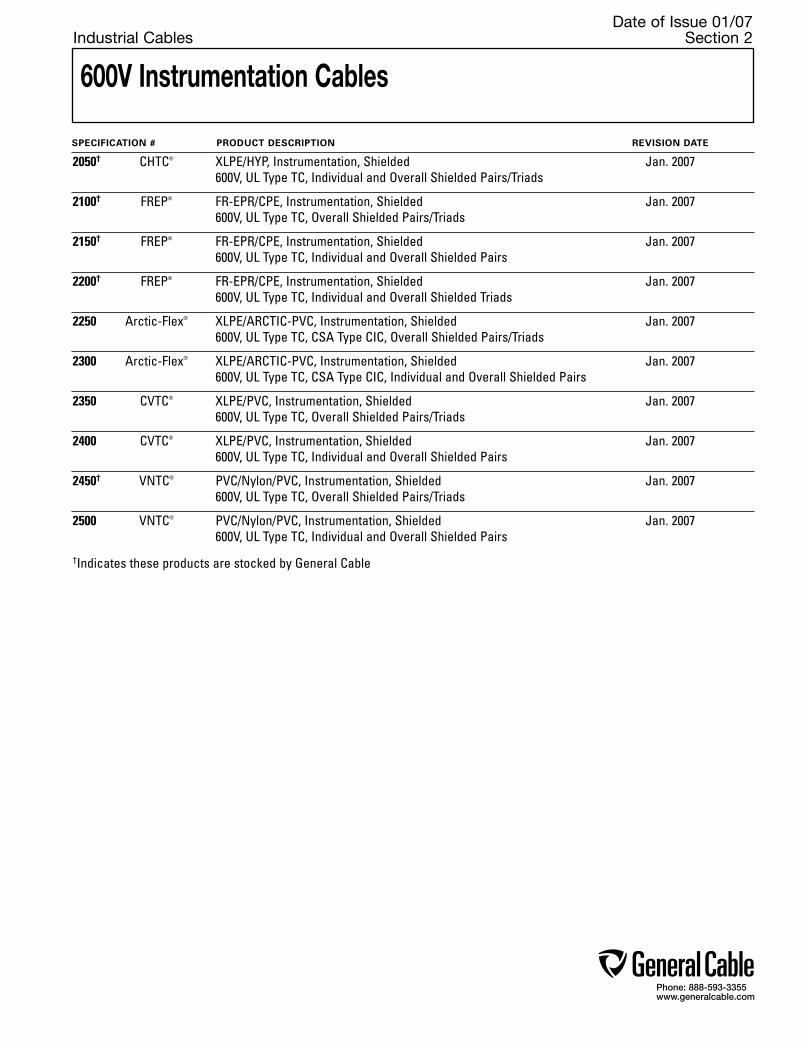
Phone: 888-593-3355www.generalcable.com
Date of Issue 01/07Industrial Cables Section 2
600V Instrumentation Cables
SPECIFICATION # PRODUCT DESCRIPTION REVISION DATE
2050† CHTC® XLPE/HYP, Instrumentation, Shielded Jan. 2007 600V, UL Type TC, Individual and Overall Shielded Pairs/Triads
2100† FREP® FR-EPR/CPE, Instrumentation, Shielded Jan. 2007 600V, UL Type TC, Overall Shielded Pairs/Triads
2150† FREP® FR-EPR/CPE, Instrumentation, Shielded Jan. 2007 600V, UL Type TC, Individual and Overall Shielded Pairs
2200† FREP® FR-EPR/CPE, Instrumentation, Shielded Jan. 2007 600V, UL Type TC, Individual and Overall Shielded Triads
2250 Arctic-Flex® XLPE/ARCTIC-PVC, Instrumentation, Shielded Jan. 2007 600V, UL Type TC, CSA Type CIC, Overall Shielded Pairs/Triads
2300 Arctic-Flex® XLPE/ARCTIC-PVC, Instrumentation, Shielded Jan. 2007 600V, UL Type TC, CSA Type CIC, Individual and Overall Shielded Pairs
2350 CVTC® XLPE/PVC, Instrumentation, Shielded Jan. 2007 600V, UL Type TC, Overall Shielded Pairs/Triads
2400 CVTC® XLPE/PVC, Instrumentation, Shielded Jan. 2007 600V, UL Type TC, Individual and Overall Shielded Pairs
2450† VNTC® PVC/Nylon/PVC, Instrumentation, Shielded Jan. 2007 600V, UL Type TC, Overall Shielded Pairs/Triads
2500 VNTC® PVC/Nylon/PVC, Instrumentation, Shielded Jan. 2007 600V, UL Type TC, Individual and Overall Shielded Pairs
†Indicates these products are stocked by General Cable

Phone: 888-593-3355www.generalcable.com
SPEC 2050January, 2007
CHTC®
XLPE/HYP, Instrumentation, Shielded600V, UL Type TC, Individual and Overall Shielded Pairs/Triads
1 18 7/.0152 0.030 0.76 0.045 1.52 0.315 8.15 13 19 49 73
1 TRI 18 7/.0152 0.030 0.76 0.045 1.14 0.335 8.51 18 26 64 95
2 18 7/.0152 0.030 0.76 0.045 1.14 0.510 12.95 28 42 92 137
4 18 7/.0152 0.030 0.76 0.060 1.52 0.630 16.00 53 79 167 249
8 18 7/.0152 0.030 0.76 0.080 2.03 0.855 21.72 104 155 326 485
12 18 7/.0152 0.030 0.76 0.080 2.03 1.030 26.16 155 231 441 656
16 18 7/.0152 0.030 0.76 0.080 2.03 1.140 28.96 206 307 554 824
20 18 7/.0152 0.030 0.76 0.080 2.03 1.265 32.13 256 381 676 1006
24 18 7/.0152 0.030 0.76 0.080 2.03 1.450 36.83 308 459 795 1183
36 18 7/.0152 0.030 0.76 0.110 2.79 1.650 41.91 461 687 1118 1664
50 18 7/.0152 0.030 0.76 0.110 2.79 2.085 52.96 637 948 1616 2405
CATALOG NUMBER
NO. OF PAIRS/TRIADS
285150337620*337630*337640*337650*337660*337670*337680*337690*337700*337710*
COND.SIZE
(AWG)
MINIMUM AVG. INSULATION THICKNESS
INCHES mm
MINIMUM AVG. JACKET
THICKNESS INCHES mm
NOMINAL CABLE O.D.
INCHES mm
COND.STRAND
COPPER WEIGHT
lbs/ 1000ft kg/km
INDIVIDUAL AND OVERALL SHIELDED PAIRS/TRIADS16 AWG CONDUCTORS
INDIVIDUAL AND OVERALL SHIELDED PAIRS/TRIADS18 AWG CONDUCTORS
Product ConstructionConductor:
• 18 AWG and 16 AWG tinned, annealed copper per ASTM B33
• Class B stranding per ASTM B8
Insulation:• Flame-retardant Cross-Linked Polyethylene (XLPE) • Color-coded: per ICEA Method 1; Pairs - black
and white. Triads - black, white and red. One conductor in each pair or triad is printed alpha-numerically for easy identification
Shield:Individual and overall shielded pairs/triads• Individual pairs/triads are 100% shielded with
Flexfoil® aluminum/polyester in contact with stranded tinned copper drain wire
• Overall shield is Flexfoil® aluminum/polyester in contact with stranded tinned copper drain wire
Jacket:• Low-Lead Hypalon® Chlorosulfonated
Polyethylene (CSPE)/Elastomer blend
Print:• GENERAL CABLE® (WC) CHTC® XX/SPS/STS
XXAWG SHIELDED XLP/HYP SHIELDED (UL) TYPE TC 600V 90˚C WET OR DRY SUN RES OIL RES I & II DAY/MONTH/YEAR OF MFG SEQUENTIAL FOOTAGE MARK
Options:• 300V Type PLTC• Bare copper conductor• Class C stranding• Overall shielded pairs/triads• EHTC®—Ethylene Propylene Rubber (EPR)
insulation• Thermoplastic Low-Smoke, Zero-Halogen (LSZH)
jacket• Other constructions available upon request
Applications: • In free air, raceways or direct burial• In wet or dry locations• Permitted for use in Class I Division 2
industrial hazardous locations per NEC
Features:• Rated at 90˚C wet or dry• Ripcord applied to all cables with jacket
thickness of 60 mils or less• Oil-resistant jacket• Sunlight- and weather-resistant• Excellent electrical, thermal and physical
properties• Excellent moisture resistance• Excellent flame resistance• “Heavy duty” rating per ICEA standards• Excellent low temperature cold bend
characteristics• Meets cold bend test at -35˚C
Compliances:Industry Compliances: • UL Type RFH-2, FFH-2 conductors • UL 1277 Type TC • UL 1581 • ICEA S-82-552 • ICEA S-73-532Flame Tests Compliances: • UL 1581 VW-1 • UL 1277 • IEEE 383 • IEEE 1202 • CSA FT-4 • ICEA T-29-520Other Compliances: • EPA 40 CFR, Part 261 for leachable lead
content per TCLP • OSHA acceptable
Packaging:• Material cut to length and shipped on
non-returnable wood reels
1 16 7/.0192 0.030 0.76 0.045 1.52 0.345 8.76 19 28 61 91
1 TRI 16 7/.0192 0.030 0.76 0.045 1.52 0.360 9.1 28 42 85 127
2 16 7/.0192 0.030 0.76 0.060 1.52 0.585 14.86 40 60 130 193
4 16 7/.0192 0.030 0.76 0.060 1.52 0.675 17.15 78 116 204 304
8 16 7/.0192 0.030 0.76 0.080 2.03 0.915 23.24 153 228 394 586
12 16 7/.0192 0.030 0.76 0.080 2.03 1.110 28.19 229 341 548 816
16 16 7/.0192 0.030 0.76 0.080 2.03 1.350 34.29 304 453 713 1061
20 16 7/.0192 0.030 0.76 0.080 2.03 1.365 34.67 380 566 850 1265
24 16 7/.0192 0.030 0.76 0.080 2.03 1.570 39.88 455 677 1001 1490
36 16 7/.0192 0.030 0.76 0.110 2.79 1.980 50.29 682 1014 1548 2304
50 16 7/.0192 0.030 0.76 0.110 2.79 2.165 54.99 946 1408 2020 3006
240990241510241010232560241000*252370337720*337730*337740*337750*337760*
NET WEIGHT
lbs/ 1000ft kg/km
Dimensions and weights are nominal; subject to industry tolerances.*Non-stock item, minimum runs apply. Please consult Customer Service for price and delivery.
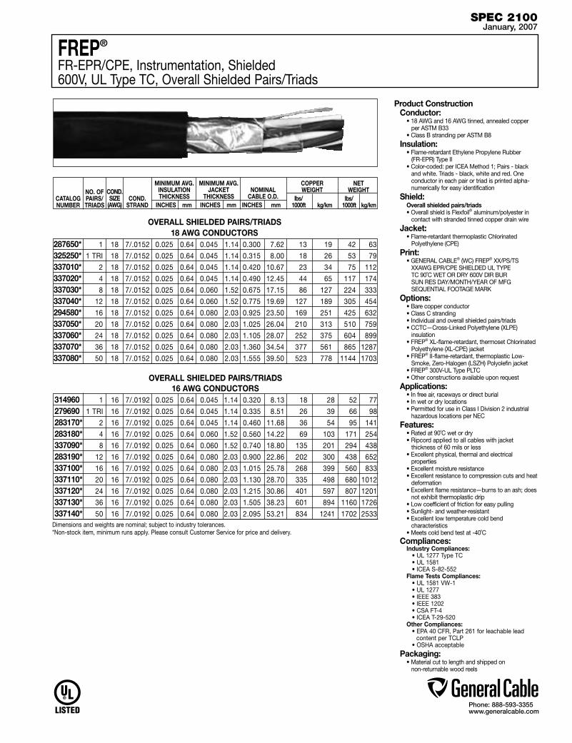
Phone: 888-593-3355www.generalcable.com
SPEC 2100January, 2007
OVERALL SHIELDED PAIRS/TRIADS
Product ConstructionConductor:
• 18 AWG and 16 AWG tinned, annealed copper per ASTM B33
• Class B stranding per ASTM B8
Insulation:• Flame-retardant Ethylene Propylene Rubber
(FR-EPR) Type II • Color-coded: per ICEA Method 1; Pairs - black
and white. Triads - black, white and red. One conductor in each pair or triad is printed alpha-numerically for easy identification
Shield:Overall shielded pairs/triads• Overall shield is Flexfoil® aluminum/polyester in
contact with stranded tinned copper drain wire
Jacket:• Flame-retardant thermoplastic Chlorinated
Polyethylene (CPE)
Print:• GENERAL CABLE® (WC) FREP® XX/PS/TS
XXAWG EPR/CPE SHIELDED UL TYPE TC 90˚C WET OR DRY 600V DIR BUR SUN RES DAY/MONTH/YEAR OF MFG SEQUENTIAL FOOTAGE MARK
Options:• Bare copper conductor• Class C stranding• Individual and overall shielded pairs/triads• CCTC—Cross-Linked Polyethylene (XLPE)
insulation• FREP® XL-flame-retardant, thermoset Chlorinated
Polyethylene (XL-CPE) jacket• FREP® II-flame-retardant, thermoplastic Low-
Smoke, Zero-Halogen (LSZH) Polyolefin jacket• FREP® 300V-UL Type PLTC• Other constructions available upon request
Applications: • In free air, raceways or direct burial• In wet or dry locations• Permitted for use in Class I Division 2 industrial
hazardous locations per NEC
Features:• Rated at 90˚C wet or dry• Ripcord applied to all cables with jacket
thickness of 60 mils or less• Excellent physical, thermal and electrical
properties• Excellent moisture resistance• Excellent resistance to compression cuts and heat
deformation• Excellent flame resistance—burns to an ash; does
not exhibit thermoplastic drip• Low coefficient of friction for easy pulling• Sunlight- and weather-resistant• Excellent low temperature cold bend
characteristics• Meets cold bend test at -40˚C
Compliances:Industry Compliances: • UL 1277 Type TC • UL 1581 • ICEA S-82-552Flame Tests Compliances: • UL 1581 VW-1 • UL 1277 • IEEE 383 • IEEE 1202 • CSA FT-4 • ICEA T-29-520Other Compliances: • EPA 40 CFR, Part 261 for leachable lead
content per TCLP • OSHA acceptable
Packaging:• Material cut to length and shipped on
non-returnable wood reels
18 AWG CONDUCTORS 1 18 7/.0152 0.025 0.64 0.045 1.14 0.300 7.62 13 19 42 63
1 TRI 18 7/.0152 0.025 0.64 0.045 1.14 0.315 8.00 18 26 53 79
2 18 7/.0152 0.025 0.64 0.045 1.14 0.420 10.67 23 34 75 112
4 18 7/.0152 0.025 0.64 0.045 1.14 0.490 12.45 44 65 117 174
8 18 7/.0152 0.025 0.64 0.060 1.52 0.675 17.15 86 127 224 333
12 18 7/.0152 0.025 0.64 0.060 1.52 0.775 19.69 127 189 305 454
16 18 7/.0152 0.025 0.64 0.080 2.03 0.925 23.50 169 251 425 632
20 18 7/.0152 0.025 0.64 0.080 2.03 1.025 26.04 210 313 510 759
24 18 7/.0152 0.025 0.64 0.080 2.03 1.105 28.07 252 375 604 899
36 18 7/.0152 0.025 0.64 0.080 2.03 1.360 34.54 377 561 865 1287
50 18 7/.0152 0.025 0.64 0.080 2.03 1.555 39.50 523 778 1144 1703
287650*325250*337010*337020*337030*337040*294580*337050*337060*337070*337080*
OVERALL SHIELDED PAIRS/TRIADS16 AWG CONDUCTORS
1 16 7/.0192 0.025 0.64 0.045 1.14 0.320 8.13 18 28 52 77
1 TRI 16 7/.0192 0.025 0.64 0.045 1.14 0.335 8.51 26 39 66 98
2 16 7/.0192 0.025 0.64 0.045 1.14 0.460 11.68 36 54 95 141
4 16 7/.0192 0.025 0.64 0.060 1.52 0.560 14.22 69 103 171 254
8 16 7/.0192 0.025 0.64 0.060 1.52 0.740 18.80 135 201 294 438
12 16 7/.0192 0.025 0.64 0.080 2.03 0.900 22.86 202 300 438 652
16 16 7/.0192 0.025 0.64 0.080 2.03 1.015 25.78 268 399 560 833
20 16 7/.0192 0.025 0.64 0.080 2.03 1.130 28.70 335 498 680 1012
24 16 7/.0192 0.025 0.64 0.080 2.03 1.215 30.86 401 597 807 1201
36 16 7/.0192 0.025 0.64 0.080 2.03 1.505 38.23 601 894 1160 1726
50 16 7/.0192 0.025 0.64 0.080 2.03 2.095 53.21 834 1241 1702 2533
314960279690283170*283180*337090*283190*337100*337110*337120*337130*337140*
CATALOG NUMBER
NO. OF PAIRS/TRIADS
MINIMUM AVG. INSULATION THICKNESS
INCHES mm
MINIMUM AVG. JACKET
THICKNESS INCHES mm
NOMINAL CABLE O.D.
INCHES mm
COND.STRAND
COPPER WEIGHT
lbs/ 1000ft kg/km
NET WEIGHT
lbs/ 1000ft kg/km
COND.SIZE
(AWG)
Dimensions and weights are nominal; subject to industry tolerances.*Non-stock item, minimum runs apply. Please consult Customer Service for price and delivery.
FREP®
FR-EPR/CPE, Instrumentation, Shielded600V, UL Type TC, Overall Shielded Pairs/Triads
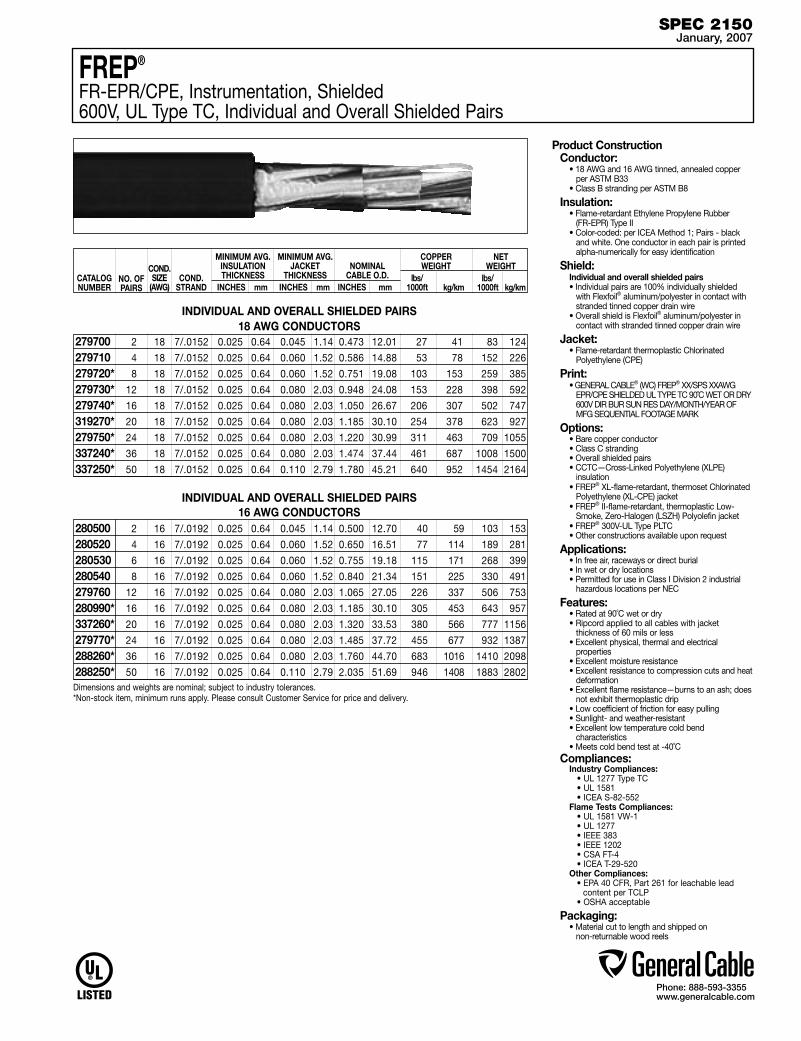
Phone: 888-593-3355www.generalcable.com
SPEC 2150January, 2007
INDIVIDUAL AND OVERALL SHIELDED PAIRS18 AWG CONDUCTORS
2 18 7/.0152 0.025 0.64 0.045 1.14 0.473 12.01 27 41 83 124
4 18 7/.0152 0.025 0.64 0.060 1.52 0.586 14.88 53 78 152 226
8 18 7/.0152 0.025 0.64 0.060 1.52 0.751 19.08 103 153 259 385
12 18 7/.0152 0.025 0.64 0.080 2.03 0.948 24.08 153 228 398 592
16 18 7/.0152 0.025 0.64 0.080 2.03 1.050 26.67 206 307 502 747
20 18 7/.0152 0.025 0.64 0.080 2.03 1.185 30.10 254 378 623 927
24 18 7/.0152 0.025 0.64 0.080 2.03 1.220 30.99 311 463 709 1055
36 18 7/.0152 0.025 0.64 0.080 2.03 1.474 37.44 461 687 1008 1500
50 18 7/.0152 0.025 0.64 0.110 2.79 1.780 45.21 640 952 1454 2164
279700279710279720*279730*279740*319270*279750*337240*337250*
INDIVIDUAL AND OVERALL SHIELDED PAIRS16 AWG CONDUCTORS
2 16 7/.0192 0.025 0.64 0.045 1.14 0.500 12.70 40 59 103 153
4 16 7/.0192 0.025 0.64 0.060 1.52 0.650 16.51 77 114 189 281
6 16 7/.0192 0.025 0.64 0.060 1.52 0.755 19.18 115 171 268 399
8 16 7/.0192 0.025 0.64 0.060 1.52 0.840 21.34 151 225 330 491
12 16 7/.0192 0.025 0.64 0.080 2.03 1.065 27.05 226 337 506 753
16 16 7/.0192 0.025 0.64 0.080 2.03 1.185 30.10 305 453 643 957
20 16 7/.0192 0.025 0.64 0.080 2.03 1.320 33.53 380 566 777 1156
24 16 7/.0192 0.025 0.64 0.080 2.03 1.485 37.72 455 677 932 1387
36 16 7/.0192 0.025 0.64 0.080 2.03 1.760 44.70 683 1016 1410 2098
50 16 7/.0192 0.025 0.64 0.110 2.79 2.035 51.69 946 1408 1883 2802
280500280520280530280540279760280990*337260*279770*288260*288250*
Product ConstructionConductor:
• 18 AWG and 16 AWG tinned, annealed copper per ASTM B33
• Class B stranding per ASTM B8
Insulation:• Flame-retardant Ethylene Propylene Rubber
(FR-EPR) Type II • Color-coded: per ICEA Method 1; Pairs - black
and white. One conductor in each pair is printed alpha-numerically for easy identification
Shield:Individual and overall shielded pairs• Individual pairs are 100% individually shielded
with Flexfoil® aluminum/polyester in contact with stranded tinned copper drain wire
• Overall shield is Flexfoil® aluminum/polyester in contact with stranded tinned copper drain wire
Jacket:• Flame-retardant thermoplastic Chlorinated
Polyethylene (CPE)
Print:• GENERAL CABLE® (WC) FREP® XX/SPS XXAWG
EPR/CPE SHIELDED UL TYPE TC 90˚C WET OR DRY 600V DIR BUR SUN RES DAY/MONTH/YEAR OF MFG SEQUENTIAL FOOTAGE MARK
Options:• Bare copper conductor• Class C stranding• Overall shielded pairs• CCTC—Cross-Linked Polyethylene (XLPE)
insulation• FREP® XL-flame-retardant, thermoset Chlorinated
Polyethylene (XL-CPE) jacket• FREP® II-flame-retardant, thermoplastic Low-
Smoke, Zero-Halogen (LSZH) Polyolefin jacket• FREP® 300V-UL Type PLTC• Other constructions available upon request
Applications: • In free air, raceways or direct burial • In wet or dry locations• Permitted for use in Class I Division 2 industrial
hazardous locations per NEC
Features:• Rated at 90˚C wet or dry• Ripcord applied to all cables with jacket
thickness of 60 mils or less• Excellent physical, thermal and electrical
properties• Excellent moisture resistance• Excellent resistance to compression cuts and heat
deformation• Excellent flame resistance—burns to an ash; does
not exhibit thermoplastic drip• Low coefficient of friction for easy pulling• Sunlight- and weather-resistant• Excellent low temperature cold bend
characteristics • Meets cold bend test at -40˚C
Compliances:Industry Compliances: • UL 1277 Type TC • UL 1581 • ICEA S-82-552Flame Tests Compliances: • UL 1581 VW-1 • UL 1277 • IEEE 383 • IEEE 1202 • CSA FT-4 • ICEA T-29-520Other Compliances: • EPA 40 CFR, Part 261 for leachable lead
content per TCLP • OSHA acceptable
Packaging:• Material cut to length and shipped on
non-returnable wood reels
CATALOG NUMBER
NO. OF PAIRS
MINIMUM AVG. INSULATION THICKNESS
INCHES mm
MINIMUM AVG. JACKET
THICKNESS INCHES mm
NOMINAL CABLE O.D.
INCHES mm
COND.STRAND
COPPER WEIGHT
lbs/ 1000ft kg/km
NET WEIGHT
lbs/ 1000ft kg/km
COND.SIZE
(AWG)
Dimensions and weights are nominal; subject to industry tolerances.*Non-stock item, minimum runs apply. Please consult Customer Service for price and delivery.
FREP®
FR-EPR/CPE, Instrumentation, Shielded600V, UL Type TC, Individual and Overall Shielded Pairs

Phone: 888-593-3355www.generalcable.com
SPEC 2200January, 2007
INDIVIDUAL AND OVERALL SHIELDED TRIADS18 AWG CONDUCTORS
Product ConstructionConductor:
• 18 AWG and 16 AWG tinned, annealed copper per ASTM B33
• Class B stranding per ASTM B8
Insulation:• Flame-retardant Ethylene Propylene Rubber
(FR-EPR) Type II • Color-coded: per ICEA Method 1; Triads - black,
white and red. One conductor in each triad is printed alpha-numerically for easy identification
Shield:Individual and overall shielded triads• Individual triads are 100% shielded with Flexfoil®
aluminum/polyester in contact with stranded tinned copper drain wire
• Overall shield is Flexfoil® aluminum/polyester in contact with stranded tinned copper drain wire
Jacket:• Flame-retardant thermoplastic Chlorinated
Polyethylene (CPE)
Print:• GENERAL CABLE® (WC) FREP® XX/STS XXAWG
EPR/CPE SHIELDED UL TYPE TC 90˚C WET OR DRY 600V DIR BUR SUN RES DAY/MONTH/YEAR OF MFG SEQUENTIAL FOOTAGE MARK
Options:• Bare copper conductor• Class C stranding• Overall shielded pairs/triads• CCTC—Cross-Linked Polyethylene (XLPE)
insulation• FREP® XL-flame-retardant, thermoset Chlorinated
Polyethylene (XL-CPE) jacket• FREP® II-flame-retardant, thermoplastic Low-
Smoke, Zero-Halogen (LSZH) polyolefin jacket• FREP® 300V-UL Type PLTC• Other constructions available upon request
Applications: • In free air, raceways or direct burial• In wet or dry locations• Permitted for use in Class I Division 2 industrial
hazardous locations per NEC
Features:• Rated at 90˚C wet or dry• Ripcord applied to all cables with jacket
thickness of 60 mils or less• Excellent physical, thermal and electrical properties• Excellent moisture resistance• Excellent resistance to compression cuts and heat
deformation• Excellent flame resistance—burns to an ash; does
not exhibit thermoplastic drip• Low coefficient of friction for easy pulling• Sunlight- and weather-resistant• Excellent low temperature cold bend
characteristics• Meets cold bend test at -40˚C
Compliances:Industry Compliances: • UL 1277 Type TC • UL 1581 • ICEA S-82-552Flame Tests Compliances: • UL 1581 VW-1 • UL 1277 • IEEE 383 • IEEE 1202 • CSA FT-4 • ICEA T-29-520Other Compliances: • EPA 40 CFR, Part 261 for leachable lead
content per TCLP • OSHA acceptable
Packaging:• Material cut to length and shipped on
non-returnable wood reels
2 TRI 18 7/.0152 0.025 0.64 0.060 1.52 0.560 14.22 38 57 127 189
4 TRI 18 7/.0152 0.025 0.64 0.060 1.52 0.640 16.26 73 109 201 299
8 TRI 18 7/.0152 0.025 0.64 0.080 2.03 0.825 20.96 144 214 343 510
12 TRI 18 7/.0152 0.025 0.64 0.080 2.03 1.065 27.05 218 324 528 786
16 TRI 18 7/.0152 0.025 0.64 0.080 2.03 1.180 29.97 290 431 675 1005
20 TRI 18 7/.0152 0.025 0.64 0.080 2.03 1.310 33.27 361 538 825 1228
24 TRI 18 7/.0152 0.025 0.64 0.080 2.03 1.500 38.10 433 645 972 1447
36 TRI 18 7/.0152 0.025 0.64 0.080 2.03 1.740 44.20 649 965 1470 2188
337150*319250*319260*337160*294540*337170*337180*337190*
INDIVIDUAL AND OVERALL SHIELDED TRIADS16 AWG CONDUCTORS
2 TRI 16 7/.0192 0.025 0.64 0.060 1.52 0.615 15.62 57 84 159 237
4 TRI 16 7/.0192 0.025 0.64 0.060 1.52 0.705 17.91 108 160 249 371
8 TRI 16 7/.0192 0.025 0.64 0.080 2.03 0.850 21.59 217 323 472 702
12 TRI 16 7/.0192 0.025 0.64 0.080 2.03 1.160 29.46 328 487 683 1016
16 TRI 16 7/.0192 0.025 0.64 0.080 2.03 1.290 32.77 436 649 879 1308
20 TRI 16 7/.0192 0.025 0.64 0.080 2.03 1.380 35.05 545 811 1058 1575
24 TRI 16 7/.0192 0.025 0.64 0.080 2.03 1.615 41.02 653 972 1266 1884
36 TRI 16 7/.0192 0.025 0.64 0.110 2.79 1.920 48.77 979 1457 1918 2854
280950*280960*280970*287410*337200*337210*337220*337230*
CATALOG NUMBER
NO. OF TRIADS
MINIMUM AVG. INSULATION THICKNESS
INCHES mm
MINIMUM AVG. JACKET
THICKNESS INCHES mm
NOMINAL CABLE O.D.
INCHES mm
COND.STRAND
COPPER WEIGHT
lbs/ 1000ft kg/km
NET WEIGHT
lbs/ 1000ft kg/km
COND.SIZE
(AWG)
Dimensions and weights are nominal; subject to industry tolerances.*Non-stock item, minimum runs apply. Please consult Customer Service for price and delivery.
FREP®
FR-EPR/CPE, Instrumentation, Shielded600V, UL Type TC, Individual and Overall Shielded Triads
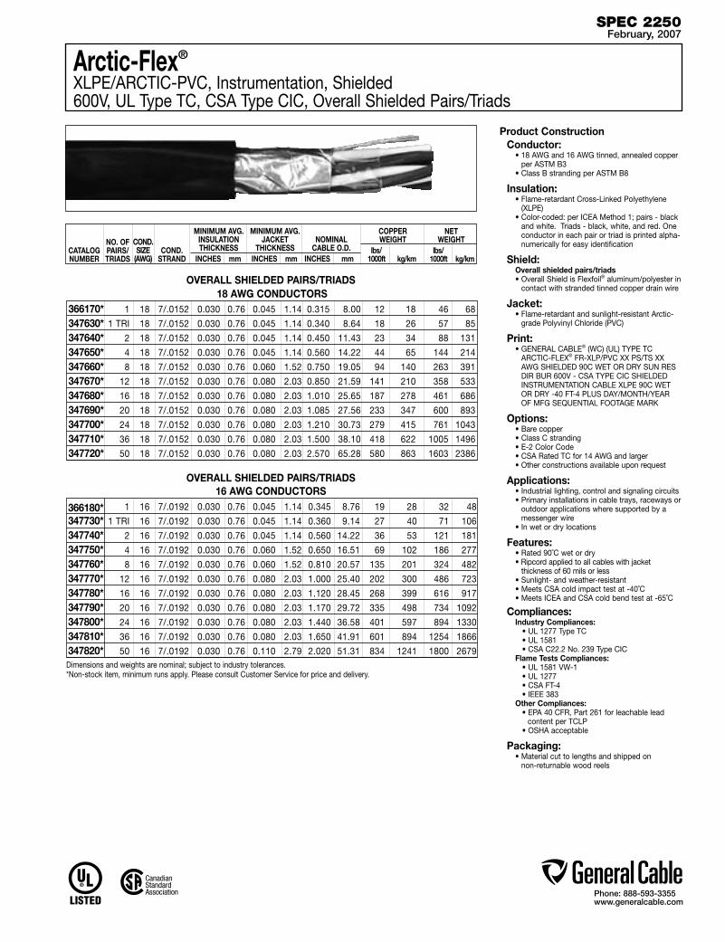
Phone: 888-593-3355www.generalcable.com
SPEC 2250February, 2007
1 18 7/.0152 0.030 0.76 0.045 1.14 0.315 8.00 12 18 46 68
1 TRI 18 7/.0152 0.030 0.76 0.045 1.14 0.340 8.64 18 26 57 85
2 18 7/.0152 0.030 0.76 0.045 1.14 0.450 11.43 23 34 88 131
4 18 7/.0152 0.030 0.76 0.045 1.14 0.560 14.22 44 65 144 214
8 18 7/.0152 0.030 0.76 0.060 1.52 0.750 19.05 94 140 263 391
12 18 7/.0152 0.030 0.76 0.080 2.03 0.850 21.59 141 210 358 533
16 18 7/.0152 0.030 0.76 0.080 2.03 1.010 25.65 187 278 461 686
20 18 7/.0152 0.030 0.76 0.080 2.03 1.085 27.56 233 347 600 893
24 18 7/.0152 0.030 0.76 0.080 2.03 1.210 30.73 279 415 761 1043
36 18 7/.0152 0.030 0.76 0.080 2.03 1.500 38.10 418 622 1005 1496
50 18 7/.0152 0.030 0.76 0.080 2.03 2.570 65.28 580 863 1603 2386
366170*347630*347640*347650*347660*347670*347680*347690*347700*347710*347720*
18 AWG CONDUCTORS
OVERALL SHIELDED PAIRS/TRIADS16 AWG CONDUCTORS
1 16 7/.0192 0.030 0.76 0.045 1.14 0.345 8.76 19 28 32 48
1 TRI 16 7/.0192 0.030 0.76 0.045 1.14 0.360 9.14 27 40 71 106
2 16 7/.0192 0.030 0.76 0.045 1.14 0.560 14.22 36 53 121 181
4 16 7/.0192 0.030 0.76 0.060 1.52 0.650 16.51 69 102 186 277
8 16 7/.0192 0.030 0.76 0.060 1.52 0.810 20.57 135 201 324 482
12 16 7/.0192 0.030 0.76 0.080 2.03 1.000 25.40 202 300 486 723
16 16 7/.0192 0.030 0.76 0.080 2.03 1.120 28.45 268 399 616 917
20 16 7/.0192 0.030 0.76 0.080 2.03 1.170 29.72 335 498 734 1092
24 16 7/.0192 0.030 0.76 0.080 2.03 1.440 36.58 401 597 894 1330
36 16 7/.0192 0.030 0.76 0.080 2.03 1.650 41.91 601 894 1254 1866
50 16 7/.0192 0.030 0.76 0.110 2.79 2.020 51.31 834 1241 1800 2679
366180*347730*347740*347750*347760*347770*347780*347790*347800*347810*347820*
Product ConstructionConductor:
• 18 AWG and 16 AWG tinned, annealed copper per ASTM B3
• Class B stranding per ASTM B8
Insulation:• Flame-retardant Cross-Linked Polyethylene
(XLPE)• Color-coded: per ICEA Method 1; pairs - black
and white. Triads - black, white, and red. One conductor in each pair or triad is printed alpha-numerically for easy identification
Shield:Overall shielded pairs/triads• Overall Shield is Flexfoil® aluminum/polyester in
contact with stranded tinned copper drain wire
Jacket:• Flame-retardant and sunlight-resistant Arctic-
grade Polyvinyl Chloride (PVC)
Print:• GENERAL CABLE® (WC) (UL) TYPE TC
ARCTIC-FLEX® FR-XLP/PVC XX PS/TS XX AWG SHIELDED 90C WET OR DRY SUN RES DIR BUR 600V - CSA TYPE CIC SHIELDED INSTRUMENTATION CABLE XLPE 90C WET OR DRY -40 FT-4 PLUS DAY/MONTH/YEAR OF MFG SEQUENTIAL FOOTAGE MARK
Options:• Bare copper• Class C stranding• E-2 Color Code• CSA Rated TC for 14 AWG and larger• Other constructions available upon request
Applications:• Industrial lighting, control and signaling circuits• Primary installations in cable trays, raceways or
outdoor applications where supported by a messenger wire
• In wet or dry locations
Features:• Rated 90˚C wet or dry • Ripcord applied to all cables with jacket
thickness of 60 mils or less• Sunlight- and weather-resistant• Meets CSA cold impact test at -40˚C• Meets ICEA and CSA cold bend test at -65˚C
Compliances:Industry Compliances: • UL 1277 Type TC • UL 1581 • CSA C22.2 No. 239 Type CICFlame Tests Compliances: • UL 1581 VW-1 • UL 1277 • CSA FT-4 • IEEE 383Other Compliances: • EPA 40 CFR, Part 261 for leachable lead
content per TCLP • OSHA acceptable
Packaging:• Material cut to lengths and shipped on
non-returnable wood reels
OVERALL SHIELDED PAIRS/TRIADS
CATALOG NUMBER
NO. OF PAIRS/TRIADS
MINIMUM AVG. INSULATION THICKNESS
INCHES mm
MINIMUM AVG. JACKET
THICKNESS INCHES mm
NOMINAL CABLE O.D.
INCHES mm
COND.STRAND
COPPER WEIGHT
lbs/ 1000ft kg/km
NET WEIGHT
lbs/ 1000ft kg/km
COND.SIZE
(AWG)
Dimensions and weights are nominal; subject to industry tolerances.*Non-stock item, minimum runs apply. Please consult Customer Service for price and delivery.
Arctic-Flex®
XLPE/ARCTIC-PVC, Instrumentation, Shielded600V, UL Type TC, CSA Type CIC, Overall Shielded Pairs/Triads
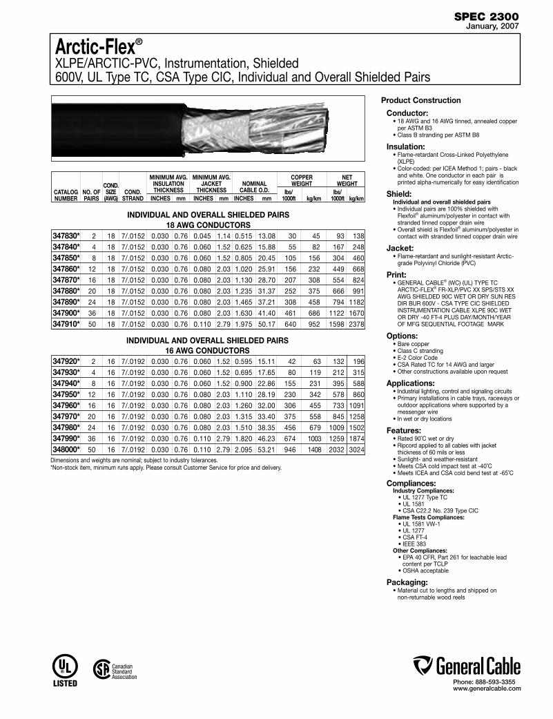
Phone: 888-593-3355www.generalcable.com
SPEC 2300January, 2007
2 18 7/.0152 0.030 0.76 0.045 1.14 0.515 13.08 30 45 93 138
4 18 7/.0152 0.030 0.76 0.060 1.52 0.625 15.88 55 82 167 248
8 18 7/.0152 0.030 0.76 0.060 1.52 0.805 20.45 105 156 304 460
12 18 7/.0152 0.030 0.76 0.080 2.03 1.020 25.91 156 232 449 668
16 18 7/.0152 0.030 0.76 0.080 2.03 1.130 28.70 207 308 554 824
20 18 7/.0152 0.030 0.76 0.080 2.03 1.235 31.37 252 375 666 991
24 18 7/.0152 0.030 0.76 0.080 2.03 1.465 37.21 308 458 794 1182
36 18 7/.0152 0.030 0.76 0.080 2.03 1.630 41.40 461 686 1122 1670
50 18 7/.0152 0.030 0.76 0.110 2.79 1.975 50.17 640 952 1598 2378
347830*347840*347850*347860*347870*347880*347890*347900*347910*
18 AWG CONDUCTORS
INDIVIDUAL AND OVERALL SHIELDED PAIRS16 AWG CONDUCTORS
2 16 7/.0192 0.030 0.76 0.060 1.52 0.595 15.11 42 63 132 196
4 16 7/.0192 0.030 0.76 0.060 1.52 0.695 17.65 80 119 212 315
8 16 7/.0192 0.030 0.76 0.060 1.52 0.900 22.86 155 231 395 588
12 16 7/.0192 0.030 0.76 0.080 2.03 1.110 28.19 230 342 578 860
16 16 7/.0192 0.030 0.76 0.080 2.03 1.260 32.00 306 455 733 1091
20 16 7/.0192 0.030 0.76 0.080 2.03 1.315 33.40 375 558 845 1258
24 16 7/.0192 0.030 0.76 0.080 2.03 1.510 38.35 456 679 1009 1502
36 16 7/.0192 0.030 0.76 0.110 2.79 1.820 46.23 674 1003 1259 1874
50 16 7/.0192 0.030 0.76 0.110 2.79 2.095 53.21 946 1408 2032 3024
347920*347930*347940*347950*347960*347970*347980*347990*348000*
INDIVIDUAL AND OVERALL SHIELDED PAIRS
CATALOG NUMBER
NO. OF PAIRS
MINIMUM AVG. INSULATION THICKNESS
INCHES mm
MINIMUM AVG. JACKET
THICKNESS INCHES mm
NOMINAL CABLE O.D.
INCHES mm
COND.STRAND
COPPER WEIGHT
lbs/ 1000ft kg/km
NET WEIGHT
lbs/ 1000ft kg/km
COND.SIZE
(AWG)
Dimensions and weights are nominal; subject to industry tolerances.*Non-stock item, minimum runs apply. Please consult Customer Service for price and delivery.
Product Construction
Conductor:• 18 AWG and 16 AWG tinned, annealed copper
per ASTM B3• Class B stranding per ASTM B8
Insulation:• Flame-retardant Cross-Linked Polyethylene
(XLPE)• Color-coded: per ICEA Method 1; pairs - black
and white. One conductor in each pair is printed alpha-numerically for easy identification
Shield:Individual and overall shielded pairs• Individual pairs are 100% shielded with
Flexfoil® aluminum/polyester in contact with stranded tinned copper drain wire
• Overall shield is Flexfoil® aluminum/polyester in contact with stranded tinned copper drain wire
Jacket:• Flame-retardant and sunlight-resistant Arctic-
grade Polyvinyl Chloride (PVC)
Print:• GENERAL CABLE® (WC) (UL) TYPE TC
ARCTIC-FLEX® FR-XLP/PVC XX SPS/STS XX AWG SHIELDED 90C WET OR DRY SUN RES DIR BUR 600V - CSA TYPE CIC SHIELDED INSTRUMENTATION CABLE XLPE 90C WET OR DRY -40 FT-4 PLUS DAY/MONTH/YEAR OF MFG SEQUENTIAL FOOTAGE MARK
Options:• Bare copper• Class C stranding• E-2 Color Code• CSA Rated TC for 14 AWG and larger• Other constructions available upon request
Applications:• Industrial lighting, control and signaling circuits • Primary installations in cable trays, raceways or
outdoor applications where supported by a messenger wire
• In wet or dry locations
Features:• Rated 90˚C wet or dry • Ripcord applied to all cables with jacket
thickness of 60 mils or less• Sunlight- and weather-resistant• Meets CSA cold impact test at -40˚C• Meets ICEA and CSA cold bend test at -65˚C
Compliances:Industry Compliances: • UL 1277 Type TC • UL 1581 • CSA C22.2 No. 239 Type CICFlame Tests Compliances: • UL 1581 VW-1 • UL 1277 • CSA FT-4 • IEEE 383Other Compliances: • EPA 40 CFR, Part 261 for leachable lead
content per TCLP • OSHA acceptable
Packaging:• Material cut to lengths and shipped on
non-returnable wood reels
Arctic-Flex®
XLPE/ARCTIC-PVC, Instrumentation, Shielded600V, UL Type TC, CSA Type CIC, Individual and Overall Shielded Pairs

Phone: 888-593-3355www.generalcable.com
SPEC 2350January, 2007
1 18 7/.0152 0.030 0.76 0.045 1.14 0.315 8.00 12 18 46 68
1 TRI 18 7/.0152 0.030 0.76 0.045 1.14 0.340 8.64 18 26 58 86
2 18 7/.0152 0.030 0.76 0.045 1.14 0.450 11.43 23 34 88 131
4 18 7/.0152 0.030 0.76 0.045 1.14 0.560 14.22 44 65 144 214
8 18 7/.0152 0.030 0.76 0.060 1.52 0.750 19.05 94 140 263 391
12 18 7/.0152 0.030 0.76 0.080 2.03 0.850 21.59 141 210 358 533
16 18 7/.0152 0.030 0.76 0.080 2.03 1.010 25.65 187 278 461 686
20 18 7/.0152 0.030 0.76 0.080 2.03 1.085 27.56 233 347 600 893
24 18 7/.0152 0.030 0.76 0.080 2.03 1.210 30.73 279 415 701 1043
36 18 7/.0152 0.030 0.76 0.080 2.03 1.500 38.10 418 622 1005 1496
50 18 7/.0152 0.030 0.76 0.080 2.03 2.570 65.28 580 863 1603 2386
366160*337270*337360*337280*337290*337300*337310*337320*337330*337340*337350*
18 AWG CONDUCTORS
1 16 7/.0192 0.030 0.76 0.045 1.14 0.345 8.76 19 28 32 48
1 TRI 16 7/.0192 0.030 0.76 0.045 1.14 0.360 9.14 27 40 72 107
2 16 7/.0192 0.030 0.76 0.045 1.14 0.560 14.22 36 53 121 180
4 16 7/.0192 0.030 0.76 0.060 1.52 0.650 16.51 69 102 186 277
8 16 7/.0192 0.030 0.76 0.060 1.52 0.810 20.57 135 201 324 482
12 16 7/.0192 0.030 0.76 0.080 2.03 1.000 25.40 202 300 486 723
16 16 7/.0192 0.030 0.76 0.080 2.03 1.120 28.45 268 399 616 917
20 16 7/.0192 0.030 0.76 0.080 2.03 1.170 29.72 335 498 734 1092
24 16 7/.0192 0.030 0.76 0.080 2.03 1.440 36.58 401 597 894 1330
36 16 7/.0192 0.030 0.76 0.080 2.03 1.650 41.91 601 894 1254 1866
50 16 7/.0192 0.030 0.76 0.110 2.79 2.020 51.31 834 1241 1800 2679
319810*319870*337370*328260*337390*337400*337410*337420*337430*337440*337450*
Product Construction
Conductor:• 18 AWG and 16 AWG bare, annealed
copper per ASTM B3• Class B stranding per ASTM B8
Insulation:• Flame-retardant Cross-Linked Polyethylene
(XLPE)• Color-coded: per ICEA Method 1; Pairs - black
and white. Triads - black, white and red. One conductor in each pair or triad is printed alpha-numerically for easy identification
Shield:Overall shielded pairs/triads• Overall shield is Flexfoil® aluminum/polyester in
contact with stranded tinned copper drain wire
Jacket:• Flame-retardant and sunlight-resistant Polyvinyl
Chloride (PVC)
Print: • GENERAL CABLE® (WC) CVTC® XX/PS/TS
XXAWG FR-XLP/PVC SHIELDED (UL)TYPE TC 90˚C WET OR DRY DIR BUR SUN RES 600V MONTH/YEAR OF MFG SEQUENTIAL FOOTAGE MARK
Options:• 300V Type PLTC• Tinned copper conductor• Class C stranding• Individual and overall shielded pairs/triads• EVTC—Ethylene Propylene Rubber (EPR)
insulation• Other constructions available upon request
Applications: • In free air, raceways or direct burial • In wet or dry locations• Permitted for use in Class I Division 2 industrial
hazardous locations per NEC
Features:• Rated at 90˚C wet or dry• Ripcord applied to all cables with jacket
thickness of 60 mils or less• Abrasion- and chemical-resistant• Excellent electrical properties• Sunlight- and weather-resistant• Meets cold bend test at -25˚C
Compliances:Industry Compliances: • UL 1277 Type TC • UL 1581 • ICEA S-82-552 • ICEA S-73-532Flame Tests Compliances: • UL 1581 VW-1 • UL 1277 • IEEE 383 • IEEE 1202 • CSA FT-4Other Compliances: • EPA 40 CFR, Part 261 for leachable lead
content per TCLP • OSHA acceptable
Packaging:• Material cut to length and shipped on
non-returnable wood reels
OVERALL SHIELDED PAIRS/TRIADS
CATALOG NUMBER
NO. OF PAIRS/TRIADS
MINIMUM AVG. INSULATION THICKNESS
INCHES mm
MINIMUM AVG. JACKET
THICKNESS INCHES mm
NOMINAL CABLE O.D.
INCHES mm
COND.STRAND
COPPER WEIGHT
lbs/ 1000ft kg/km
NET WEIGHT
lbs/ 1000ft kg/km
COND.SIZE
(AWG)
Dimensions and weights are nominal; subject to industry tolerances.*Non-stock item, minimum runs apply. Please consult Customer Service for price and delivery.
CVTC®
XLPE/PVC, Instrumentation, Shielded600V, UL Type TC, Overall Shielded Pairs/Triads
OVERALL SHIELDED PAIRS/TRIADS16 AWG CONDUCTORS
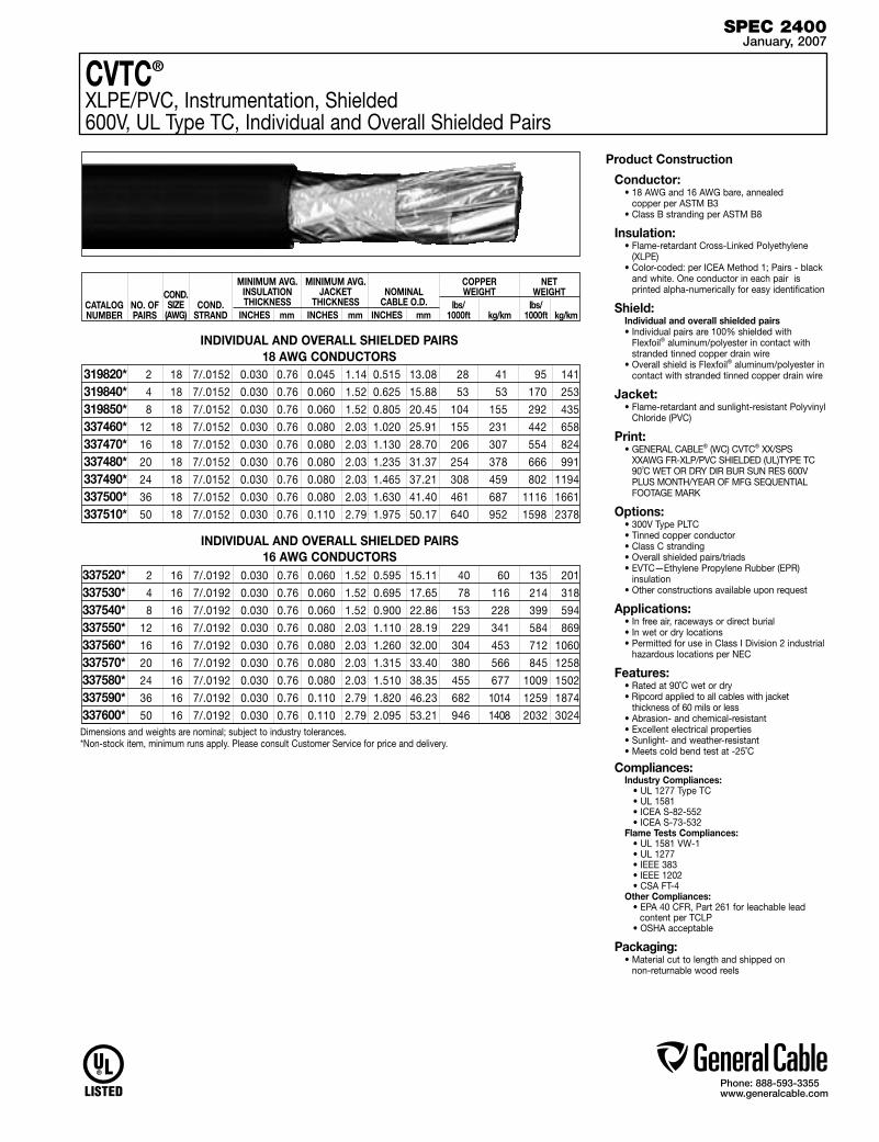
Phone: 888-593-3355www.generalcable.com
SPEC 2400January, 2007
CVTC®
XLPE/PVC, Instrumentation, Shielded600V, UL Type TC, Individual and Overall Shielded Pairs
2 18 7/.0152 0.030 0.76 0.045 1.14 0.515 13.08 28 41 95 141
4 18 7/.0152 0.030 0.76 0.060 1.52 0.625 15.88 53 53 170 253
8 18 7/.0152 0.030 0.76 0.060 1.52 0.805 20.45 104 155 292 435
12 18 7/.0152 0.030 0.76 0.080 2.03 1.020 25.91 155 231 442 658
16 18 7/.0152 0.030 0.76 0.080 2.03 1.130 28.70 206 307 554 824
20 18 7/.0152 0.030 0.76 0.080 2.03 1.235 31.37 254 378 666 991
24 18 7/.0152 0.030 0.76 0.080 2.03 1.465 37.21 308 459 802 1194
36 18 7/.0152 0.030 0.76 0.080 2.03 1.630 41.40 461 687 1116 1661
50 18 7/.0152 0.030 0.76 0.110 2.79 1.975 50.17 640 952 1598 2378
319820*319840*319850*337460*337470*337480*337490*337500*337510*
18 AWG CONDUCTORS
INDIVIDUAL AND OVERALL SHIELDED PAIRS16 AWG CONDUCTORS
2 16 7/.0192 0.030 0.76 0.060 1.52 0.595 15.11 40 60 135 201
4 16 7/.0192 0.030 0.76 0.060 1.52 0.695 17.65 78 116 214 318
8 16 7/.0192 0.030 0.76 0.060 1.52 0.900 22.86 153 228 399 594
12 16 7/.0192 0.030 0.76 0.080 2.03 1.110 28.19 229 341 584 869
16 16 7/.0192 0.030 0.76 0.080 2.03 1.260 32.00 304 453 712 1060
20 16 7/.0192 0.030 0.76 0.080 2.03 1.315 33.40 380 566 845 1258
24 16 7/.0192 0.030 0.76 0.080 2.03 1.510 38.35 455 677 1009 1502
36 16 7/.0192 0.030 0.76 0.110 2.79 1.820 46.23 682 1014 1259 1874
50 16 7/.0192 0.030 0.76 0.110 2.79 2.095 53.21 946 1408 2032 3024
337520*337530*337540*337550*337560*337570*337580*337590*337600*
Product Construction
Conductor:• 18 AWG and 16 AWG bare, annealed
copper per ASTM B3• Class B stranding per ASTM B8
Insulation:• Flame-retardant Cross-Linked Polyethylene
(XLPE)• Color-coded: per ICEA Method 1; Pairs - black
and white. One conductor in each pair is printed alpha-numerically for easy identification
Shield:Individual and overall shielded pairs• Individual pairs are 100% shielded with
Flexfoil® aluminum/polyester in contact with stranded tinned copper drain wire
• Overall shield is Flexfoil® aluminum/polyester in contact with stranded tinned copper drain wire
Jacket:• Flame-retardant and sunlight-resistant Polyvinyl
Chloride (PVC)
Print: • GENERAL CABLE® (WC) CVTC® XX/SPS
XXAWG FR-XLP/PVC SHIELDED (UL)TYPE TC 90˚C WET OR DRY DIR BUR SUN RES 600V PLUS MONTH/YEAR OF MFG SEQUENTIAL FOOTAGE MARK
Options:• 300V Type PLTC• Tinned copper conductor• Class C stranding• Overall shielded pairs/triads• EVTC—Ethylene Propylene Rubber (EPR)
insulation• Other constructions available upon request
Applications: • In free air, raceways or direct burial • In wet or dry locations• Permitted for use in Class I Division 2 industrial
hazardous locations per NEC
Features:• Rated at 90˚C wet or dry• Ripcord applied to all cables with jacket
thickness of 60 mils or less• Abrasion- and chemical-resistant• Excellent electrical properties• Sunlight- and weather-resistant • Meets cold bend test at -25˚C
Compliances:Industry Compliances: • UL 1277 Type TC • UL 1581 • ICEA S-82-552 • ICEA S-73-532Flame Tests Compliances: • UL 1581 VW-1 • UL 1277 • IEEE 383 • IEEE 1202 • CSA FT-4Other Compliances: • EPA 40 CFR, Part 261 for leachable lead
content per TCLP • OSHA acceptable
Packaging:• Material cut to length and shipped on
non-returnable wood reels
INDIVIDUAL AND OVERALL SHIELDED PAIRS
CATALOG NUMBER
NO. OF PAIRS
MINIMUM AVG. INSULATION THICKNESS
INCHES mm
MINIMUM AVG. JACKET
THICKNESS INCHES mm
NOMINAL CABLE O.D.
INCHES mm
COND.STRAND
COPPER WEIGHT
lbs/ 1000ft kg/km
NET WEIGHT
lbs/ 1000ft kg/km
COND.SIZE
(AWG)
Dimensions and weights are nominal; subject to industry tolerances.*Non-stock item, minimum runs apply. Please consult Customer Service for price and delivery.

Phone: 888-593-3355www.generalcable.com
SPEC 2450January, 2007
VNTC®
PVC/Nylon/PVC, Instrumentation, Shielded600V, UL Type TC, Overall Shielded Pairs/Triads
18 AWG CONDUCTORS
OVERALL SHIELDED PAIRS/TRIADS16 AWG CONDUCTORS
1 16 7/.0192 0.020 0.51 0.045 1.14 0.300 7.62 20 29 52 77
1 TRI 16 7/.0192 0.020 0.51 0.045 1.14 0.315 8.00 27 40 61 91
2 16 7/.0192 0.020 0.51 0.045 1.14 0.470 11.94 37 54 93 138
3 16 7/.0192 0.020 0.51 0.045 1.14 0.505 12.83 53 79 117 174
4 16 7/.0192 0.020 0.51 0.060 1.52 0.575 14.61 69 103 160 238
5 16 7/.0192 0.020 0.51 0.060 1.52 0.610 15.49 87 129 190 283
7 16 7/.0192 0.020 0.51 0.060 1.52 0.630 16.00 117 174 239 356
12 16 7/.0192 0.020 0.51 0.060 1.52 0.825 20.96 201 299 370 551
16 16 7/.0192 0.020 0.51 0.080 2.03 0.970 24.64 267 397 513 763
20 16 7/.0192 0.020 0.51 0.080 2.03 1.010 25.65 337 502 628 935
24 16 7/.0192 0.020 0.51 0.080 2.03 1.135 28.83 398 592 740 1101
36 16 7/.0192 0.020 0.51 0.080 2.03 1.375 34.93 595 886 1063 1582
50 16 7/.0192 0.020 0.51 0.080 2.03 1.570 39.88 833 1240 1435 2136
230830 230840 238410*239200*230790*336870*336880*244590*244610*336890*230780*230820*230810*
Product Construction
Conductor:• 18 AWG thru 14 AWG bare, annealed
copper per ASTM B3• Class B stranding per ASTM B8
Insulation:• Flame-retardant Polyvinyl Chloride (PVC) with
clear Polyamide (nylon)• Color-coded: per ICEA Method 1; Pairs - black
and white. Triads - black, white and red. One conductor in each pair or triad is printed alpha-numerically for easy identification
Shield:Overall shielded pairs/triads• Overall shield is Flexfoil® aluminum/polyester in
contact with stranded tinned copper drain wire
Jacket:• Flame-retardant, moisture- and sunlight-
resistant Polyvinyl Chloride (PVC)
Print: • GENERAL CABLE® (WC) VNTC® XX/PS/TS
XXAWG SHIELDED (UL) TYPE TC 600V TFN SUN RES DIR BUR DAY/MONTH/YEAR OF MFG SEQUENTIAL FOOTAGE MARK
Options:• Tinned copper conductor• Class C stranding• Individual and overall shielded pairs/triads• Other constructions available upon request
Applications: • In free air, raceways or direct burial • In wet or dry locations• Permitted for use in Class I Division 2 industrial
hazardous locations per NEC
Features:• Rated at 90˚C dry, 75˚C wet• Ripcord applied to all cables with jacket
thickness of 60 mils or less• Provides sunlight, cold bend and cold impact
resistance• Offer the smallest cable O.D. available for
suitable applications• Provides excellent oil and chemical
resistance• Provides a long service life• Meets cold bend test at -25˚C
Compliances:Industry Compliances: • UL 1277 Type TC • UL 1581 • NEC Type TFN conductorsFlame Tests Compliances: • UL 1277 • IEEE 383 • IEEE 1202 • CSA FT-4Other Compliances: • EPA 40 CFR, Part 261 for leachable lead
content per TCLP • OSHA acceptable
Packaging:• Material cut to length and shipped on
non-returnable wood reels
OVERALL SHIELDED PAIRS/TRIADS
1 18 7/.0152 0.020 0.51 0.045 1.14 0.280 7.11 12 19 41 61
1 TRI 18 7/.0152 0.020 0.51 0.045 1.14 0.300 7.62 18 27 49 73
2 18 7/.0152 0.020 0.51 0.045 1.14 0.440 11.18 23 34 72 107
3 18 7/.0152 0.020 0.51 0.045 1.14 0.465 11.81 33 50 90 134
4 18 7/.0152 0.020 0.51 0.045 1.14 0.505 12.83 44 65 110 164
5 18 7/.0152 0.020 0.51 0.060 1.52 0.570 14.48 55 82 144 214
7 18 7/.0152 0.020 0.51 0.060 1.52 0.585 14.86 75 112 177 263
12 18 7/.0152 0.020 0.51 0.060 1.52 0.770 19.56 127 189 277 412
16 18 7/.0152 0.020 0.51 0.080 2.03 0.825 20.96 168 250 355 528
20 18 7/.0152 0.020 0.51 0.080 2.03 0.905 22.99 210 313 455 677
24 18 7/.0152 0.020 0.51 0.080 2.03 1.020 25.91 252 375 544 810
36 18 7/.0152 0.020 0.51 0.080 2.03 1.150 29.21 378 562 763 1135
50 18 7/.0152 0.020 0.51 0.080 2.03 1.405 35.69 525 781 1036 1542
CATALOG NUMBER
NO. OF PAIRS/TRIADS
MINIMUM AVG. INSULATION THICKNESS
INCHES mm
MINIMUM AVG. JACKET
THICKNESS INCHES mm
NOMINAL CABLE O.D.
INCHES mm
COND.STRAND
COPPER WEIGHT
lbs/ 1000ft kg/km
COND.SIZE
(AWG)
235020 239210 235910 319740*235980 336830*336840*230760*270970*336850*230750*230800*336860*
OVERALL SHIELDED PAIRS/TRIADS14 AWG CONDUCTORS
1 14 7/.0242 0.015 0.38 0.045 1.14 0.325 8.26 28 42 62 92237490 Dimensions and weights are nominal; subject to industry tolerances.*Non-stock item, minimum runs apply. Please consult Customer Service for price and delivery.
NET WEIGHT
lbs/ 1000ft kg/km

Phone: 888-593-3355www.generalcable.com
SPEC 2500January, 2007
2 18 7/.0152 0.020 0.51 0.045 1.14 0.445 11.30 28 41 84 125
3 18 7/.0152 0.020 0.51 0.045 1.14 0.480 12.19 46 68 106 158
4 18 7/.0152 0.020 0.51 0.045 1.14 0.555 14.10 53 79 145 216
5 18 7/.0152 0.020 0.51 0.060 1.52 0.580 14.73 74 110 169 252
7 18 7/.0152 0.020 0.51 0.060 1.52 0.650 16.51 102 152 219 326
12 18 7/.0152 0.020 0.51 0.060 1.52 0.845 21.46 154 230 350 521
16 18 7/.0152 0.020 0.51 0.080 2.03 0.960 24.38 229 341 473 704
20 18 7/.0152 0.020 0.51 0.080 2.03 1.050 26.67 283 421 594 884
24 18 7/.0152 0.020 0.51 0.080 2.03 1.175 29.85 340 506 689 1025
36 18 7/.0152 0.020 0.51 0.080 2.03 1.380 35.05 508 756 979 1457
50 18 7/.0152 0.020 0.51 0.080 2.03 1.615 41.02 705 1049 1371 1960
235970*336900*235900*336910*336920*241020*336930*336940*241030*243880*256300*
18 AWG CONDUCTORS
INDIVIDUAL AND OVERALL SHIELDED PAIRS16 AWG CONDUCTORS
2 16 7/.0192 0.020 0.51 0.045 1.14 0.495 12.57 44 65 105 156
3 16 7/.0192 0.020 0.51 0.045 1.14 0.520 13.21 64 95 137 204
4 16 7/.0192 0.020 0.51 0.045 1.14 0.600 15.24 84 125 188 280
5 16 7/.0192 0.020 0.51 0.060 1.52 0.655 16.64 105 157 224 333
7 16 7/.0192 0.020 0.51 0.060 1.52 0.710 18.03 145 216 290 432
12 16 7/.0192 0.020 0.51 0.060 1.52 0.940 23.88 244 363 498 741
16 16 7/.0192 0.020 0.51 0.080 2.03 1.055 26.80 324 482 635 945
20 16 7/.0192 0.020 0.51 0.080 2.03 1.175 29.85 407 605 768 1143
24 16 7/.0192 0.020 0.51 0.080 2.03 1.350 34.29 486 724 903 1344
36 16 7/.0192 0.020 0.51 0.080 2.03 1.480 37.59 732 1089 1290 1920
50 16 7/.0192 0.020 0.51 0.080 2.03 1.810 45.97 1011 1504 1809 2692
237180*235990*237160*336950*336960*242870*237130*277820*242860*243890*244600*
Product Construction
Conductor:• 18 AWG and 16 AWG bare, annealed
copper per ASTM B3• Class B stranding per ASTM B8
Insulation:• Flame-retardant Polyvinyl Chloride (PVC) with
clear Polyamide (nylon)• Color-coded: per ICEA Method 1; Pairs - black
and white. One conductor in each pair is printed alpha-numerically for easy identification
Shield:Individual and overall shielded pairs• Individual pairs are 100% shielded with
Flexfoil® aluminum/polyester in contact with stranded tinned copper drain wire
• Overall shield is Flexfoil® aluminum/polyester in contact with stranded tinned copper drain wire
Jacket:• Flame-retardant and sunlight-resistant Polyvinyl
Chloride (PVC)
Print: • GENERAL CABLE® (WC) VNTC® XX/SPS
XXAWG SHIELDED (UL) TYPE TC 600V TFN SUN RES DIR BUR PLUS DAY/MONTH/YEAR OF MFG SEQUENTIAL FOOTAGE MARK
Options:• Tinned copper conductor• Class C stranding• Overall shielded pairs/triads• Other constructions available upon request
Applications: • In free air, raceways or direct burial • In wet or dry locations• Permitted for use in Class I Division 2 industrial
hazardous locations per NEC
Features:• Rated at 90˚C dry, 75˚C wet• Ripcord applied to all cables with jacket
thickness of 60 mils or less• Provides sunlight, cold bend and cold impact
resistance• Offer the smallest cable O.D. available for
suitable applications• Provides excellent oil and chemical
resistance• Provides a long service life• Meets cold bend test at -25˚C
Compliances:Industry Compliances: • UL 1277 Type TC • UL 1581 • NEC Type TFN conductorsFlame Tests Compliances: • UL 1277 • IEEE 383 • IEEE 1202 • CSA FT-4Other Compliances: • EPA 40 CFR, Part 261 for leachable lead
content per TCLP • OSHA acceptable
Packaging:• Material cut to length and shipped on
non-returnable wood reels
INDIVIDUAL AND OVERALL SHIELDED PAIRS
CATALOG NUMBER
NO. OF PAIRS
MINIMUM AVG. INSULATION THICKNESS
INCHES mm
MINIMUM AVG. JACKET
THICKNESS INCHES mm
NOMINAL CABLE O.D.
INCHES mm
COND.STRAND
COPPER WEIGHT
lbs/ 1000ft kg/km
NET WEIGHT
lbs/ 1000ft kg/km
COND.SIZE
(AWG)
Dimensions and weights are nominal; subject to industry tolerances.*Non-stock item, minimum runs apply. Please consult Customer Service for price and delivery.
VNTC®
PVC/Nylon/PVC, Instrumentation, Shielded600V, UL Type TC, Individual and Overall Shielded Pairs
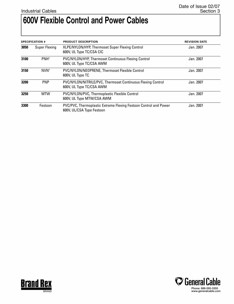
Phone: 888-593-3355www.generalcable.com
600V Flexible Control and Power Cables
Date of Issue 02/07Industrial Cables Section 3
SPECIFICATION # PRODUCT DESCRIPTION REVISION DATE
3050 Super Flexing XLPE/NYLON/HYP, Thermoset Super Flexing Control Jan. 2007 600V, UL Type TC/CSA CIC
3100 PNH® PVC/NYLON/HYP, Thermoset Continuous Flexing Control Jan. 2007 600V, UL Type TC/CSA AWM
3150 NVN® PVC/NYLON/NEOPRENE, Thermoset Flexible Control Jan. 2007 600V, UL Type TC
3200 PNP PVC/NYLON/NITRILE/PVC, Thermoset Continuous Flexing Control Jan. 2007 600V, UL Type TC/CSA AWM
3250 MTW PVC/NYLON/PVC, Thermoplastic Flexible Control Jan. 2007 600V, UL Type MTW/CSA AWM
3300 Festoon PVC/PVC, Thermoplastic Extreme Flexing Festoon Control and Power Jan. 2007 600V, UL/CSA Type Festoon
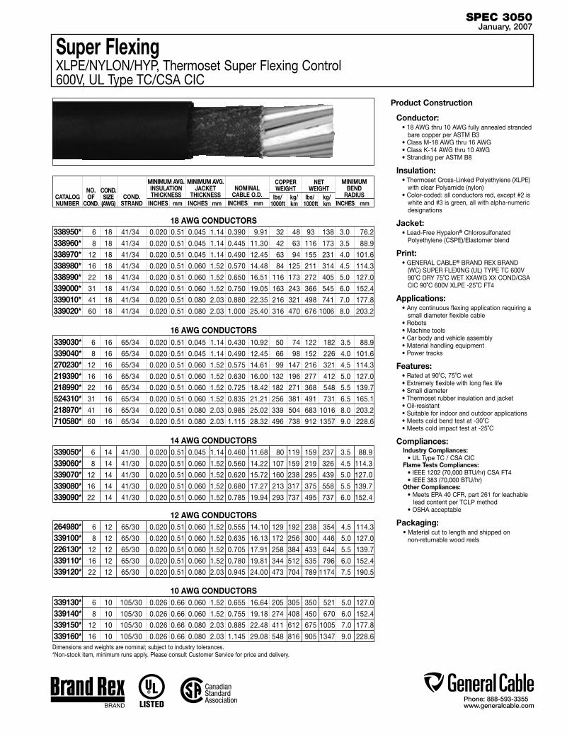
Phone: 888-593-3355www.generalcable.com
SPEC 3050January, 2007
CATALOG NUMBER
NO. OF
COND.
MINIMUM AVG. INSULATION THICKNESS
INCHES mm
MINIMUM AVG. JACKET
THICKNESS INCHES mm
MINIMUM BEND
RADIUS INCHES mm
COND.STRAND
COPPER WEIGHT
lbs/ kg/ 1000ft km
NET WEIGHT
lbs/ kg/ 1000ft km
Super FlexingXLPE/NYLON/HYP, Thermoset Super Flexing Control600V, UL Type TC/CSA CIC
14 AWG CONDUCTORS 6 14 41/30 0.020 0.51 0.045 1.14 0.460 11.68 80 119 159 237 3.5 88.9
8 14 41/30 0.020 0.51 0.060 1.52 0.560 14.22 107 159 219 326 4.5 114.3
12 14 41/30 0.020 0.51 0.060 1.52 0.620 15.72 160 238 295 439 5.0 127.0
16 14 41/30 0.020 0.51 0.060 1.52 0.680 17.27 213 317 375 558 5.5 139.7
22 14 41/30 0.020 0.51 0.060 1.52 0.785 19.94 293 737 495 737 6.0 152.4
339050*339060*339070*339080*339090*
12 AWG CONDUCTORS 6 12 65/30 0.020 0.51 0.060 1.52 0.555 14.10 129 192 238 354 4.5 114.3
8 12 65/30 0.020 0.51 0.060 1.52 0.635 16.13 172 256 300 446 5.0 127.0
12 12 65/30 0.020 0.51 0.060 1.52 0.705 17.91 258 384 433 644 5.5 139.7
16 12 65/30 0.020 0.51 0.060 1.52 0.780 19.81 344 512 535 796 6.0 152.4
22 12 65/30 0.020 0.51 0.080 2.03 0.945 24.00 473 704 789 1174 7.5 190.5
264980*339100*226130*339110*339120*
10 AWG CONDUCTORS 6 10 105/30 0.026 0.66 0.060 1.52 0.655 16.64 205 305 350 521 5.0 127.0
8 10 105/30 0.026 0.66 0.060 1.52 0.755 19.18 274 408 450 670 6.0 152.4
12 10 105/30 0.026 0.66 0.080 2.03 0.885 22.48 411 612 675 1005 7.0 177.8
16 10 105/30 0.026 0.66 0.080 2.03 1.145 29.08 548 816 905 1347 9.0 228.6
339130*339140*339150*339160*
Product Construction
Conductor:• 18 AWG thru 10 AWG fully annealed stranded
bare copper per ASTM B3• Class M-18 AWG thru 16 AWG• Class K-14 AWG thru 10 AWG• Stranding per ASTM B8
Insulation:• Thermoset Cross-Linked Polyethylene (XLPE)
with clear Polyamide (nylon)• Color-coded: all conductors red, except #2 is
white and #3 is green, all with alpha-numeric designations
Jacket:• Lead-Free Hypalon® Chlorosulfonated
Polyethylene (CSPE)/Elastomer blend
Print: • GENERAL CABLE® BRAND REX BRAND
(WC) SUPER FLEXING (UL) TYPE TC 600V 90˚C DRY 75˚C WET XXAWG XX COND/CSA CIC 90˚C 600V XLPE -25˚C FT4
Applications: • Any continuous flexing application requiring a
small diameter flexible cable• Robots• Machine tools• Car body and vehicle assembly• Material handling equipment• Power tracks
Features:• Rated at 90˚C, 75˚C wet• Extremely flexible with long flex life• Small diameter• Thermoset rubber insulation and jacket• Oil-resistant• Suitable for indoor and outdoor applications• Meets cold bend test at -30˚C• Meets cold impact test at -25˚C
Compliances:Industry Compliances: • UL Type TC / CSA CICFlame Tests Compliances: • IEEE 1202 (70,000 BTU/hr) CSA FT4 • IEEE 383 (70,000 BTU/hr)Other Compliances: • Meets EPA 40 CFR, part 261 for leachable lead content per TCLP method • OSHA acceptable
Packaging:• Material cut to length and shipped on
non-returnable wood reels
6 18 41/34 0.020 0.51 0.045 1.14 0.390 9.91 32 48 93 138 3.0 76.2
8 18 41/34 0.020 0.51 0.045 1.14 0.445 11.30 42 63 116 173 3.5 88.9
12 18 41/34 0.020 0.51 0.045 1.14 0.490 12.45 63 94 155 231 4.0 101.6
16 18 41/34 0.020 0.51 0.060 1.52 0.570 14.48 84 125 211 314 4.5 114.3
22 18 41/34 0.020 0.51 0.060 1.52 0.650 16.51 116 173 272 405 5.0 127.0
31 18 41/34 0.020 0.51 0.060 1.52 0.750 19.05 163 243 366 545 6.0 152.4
41 18 41/34 0.020 0.51 0.080 2.03 0.880 22.35 216 321 498 741 7.0 177.8
60 18 41/34 0.020 0.51 0.080 2.03 1.000 25.40 316 470 676 1006 8.0 203.2
338950*338960*338970*338980*338990*339000*339010*339020*
18 AWG CONDUCTORS
6 16 65/34 0.020 0.51 0.045 1.14 0.430 10.92 50 74 122 182 3.5 88.9
8 16 65/34 0.020 0.51 0.045 1.14 0.490 12.45 66 98 152 226 4.0 101.6
12 16 65/34 0.020 0.51 0.060 1.52 0.575 14.61 99 147 216 321 4.5 114.3
16 16 65/34 0.020 0.51 0.060 1.52 0.630 16.00 132 196 277 412 5.0 127.0
22 16 65/34 0.020 0.51 0.060 1.52 0.725 18.42 182 271 368 548 5.5 139.7
31 16 65/34 0.020 0.51 0.060 1.52 0.835 21.21 256 381 491 731 6.5 165.1
41 16 65/34 0.020 0.51 0.080 2.03 0.985 25.02 339 504 683 1016 8.0 203.2
60 16 65/34 0.020 0.51 0.080 2.03 1.115 28.32 496 738 912 1357 9.0 228.6
339030*339040*270230*219390*218990*524310*218970*710580*
16 AWG CONDUCTORS
NOMINAL CABLE O.D.
INCHES mm
COND.SIZE
(AWG)
Dimensions and weights are nominal; subject to industry tolerances.*Non-stock item, minimum runs apply. Please consult Customer Service for price and delivery.

Phone: 888-593-3355www.generalcable.com
SPEC 3100January, 2007
PNH®
PVC/NYLON/HYP, Thermoset Continuous Flexing Control600V, UL Type TC/CSA AWM
6 18 41/34 0.020 0.51 0.045 1.14 0.390 9.91 32 48 93 138 3.0 76.2
8 18 41/34 0.020 0.51 0.045 1.14 0.445 11.30 42 63 116 173 3.5 88.9
12 18 41/34 0.020 0.51 0.045 1.14 0.490 12.45 63 94 155 231 4.0 101.6
16 18 41/34 0.020 0.51 0.060 1.52 0.570 14.48 84 125 211 314 4.5 114.3
22 18 41/34 0.020 0.51 0.060 1.52 0.650 16.51 112 167 272 405 5.0 127.0
CATALOG NUMBER
NO. OF
COND.
338470*338480*338490*338500*338510*
MINIMUM AVG. INSULATION THICKNESS
INCHES mm
MINIMUM AVG. JACKET
THICKNESSINCHES mm
MINIMUM BEND
RADIUSINCHES mm
COND.STRAND
COPPER WEIGHT
lbs/ kg/ 1000ft km
NET WEIGHT
lbs/ kg/ 1000ft km
18 AWG CONDUCTORS
6 16 65/34 0.020 0.51 0.045 1.14 0.430 10.92 50 74 122 182 3.5 88.9
8 16 65/34 0.020 0.51 0.045 1.14 0.490 12.45 66 98 152 226 3.9 99.1
12 16 65/34 0.020 0.51 0.060 1.52 0.575 14.61 99 147 216 321 4.5 114.3
16 16 65/34 0.020 0.51 0.060 1.52 0.630 16.00 132 196 277 412 5.0 127.0
22 16 65/34 0.020 0.51 0.060 1.52 0.725 18.42 182 271 368 548 5.5 139.7
338520*338530*338540*338550*338560*
16 AWG CONDUCTORS
14 AWG CONDUCTORS 6 14 41/30 0.020 0.51 0.045 1.14 0.460 11.68 80 119 159 186 3.7 94.0
8 14 41/30 0.020 0.51 0.060 1.52 0.560 14.22 107 159 219 326 4.5 114.3
12 14 41/30 0.020 0.51 0.060 1.52 0.670 17.02 160 238 295 439 5.0 127.0
16 14 41/30 0.020 0.51 0.060 1.52 0.680 17.27 213 317 375 558 5.5 139.7
22 14 41/30 0.020 0.51 0.060 1.52 0.785 19.94 293 436 495 436 6.0 152.4
338570*338580*338590*338600*338610*
6 12 65/30 0.020 0.51 0.060 1.52 0.555 14.10 129 192 238 354 4.5 114.3
8 12 65/30 0.020 0.51 0.060 1.52 0.635 16.13 172 256 300 446 5.0 127.0
12 12 65/30 0.020 0.51 0.060 1.52 0.705 17.91 258 384 433 644 5.5 139.7
16 12 65/30 0.020 0.51 0.060 1.52 0.780 19.81 344 512 535 796 6.0 152.4
22 12 65/30 0.020 0.51 0.080 2.03 0.945 24.00 473 704 789 1174 7.5 190.5
338620*338630*338640*338650*338660*
Product Construction
Conductor:• 18 AWG thru 12 AWG fully annealed stranded
bare copper per ASTM B3• Class M-18 AWG thru 16 AWG• Class K-14 AWG thru 12 AWG• Stranding per ASTM B8
Insulation:• Flame-retardant Polyvinyl Chloride (PVC) with
clear Polyamide (nylon)• Color-coded: all conductors are red, except
#2 is white and #3 is green. All with alpha-numeric designations
Jacket:• Lead-Free Hypalon® Chlorosulfonated
Polyethylene (CSPE)/Elastomer blend
Print: • GENERAL CABLE® BRAND REX BRAND
(WC) PNH FLEX 90˚C 600V TYPE TC XX/C XXAWG(TFFN) OR (THHW/THWN) (UL)/CSA AWM IIA 90˚C 600V FT1
Applications: • Any continuous flexing application requiring a
small diameter flexible cable• Robots• Machine tools• Car body and vehicle assembly• Material handling equipment• Power tracks
Features:• Rated at 90˚C• Extremely flexible with long flex life• Small diameter• Thermoset rubber jacket• Oil-resistant• Suitable for indoor or outdoor applications• Meets cold bend test at -40˚C
Compliances:Industry Compliances: • UL Type TC / CSA AWMFlame Tests Compliances: • IEEE 1202 (70,000 BTU/hr) CSA FT4 • IEEE 383 (70,000 BTU/hr)Other Compliances: • Meets EPA 40 CFR, part 261 for leachable lead content per TCLP method • OSHA acceptable
Packaging:• Material cut to length and shipped on
non-returnable wood reels
NOMINAL CABLE O.D.
INCHES mm
COND.SIZE
(AWG)
Dimensions and weights are nominal; subject to industry tolerances.*Non-stock item, minimum runs apply. Please consult Customer Service for price and delivery.
12 AWG CONDUCTORS
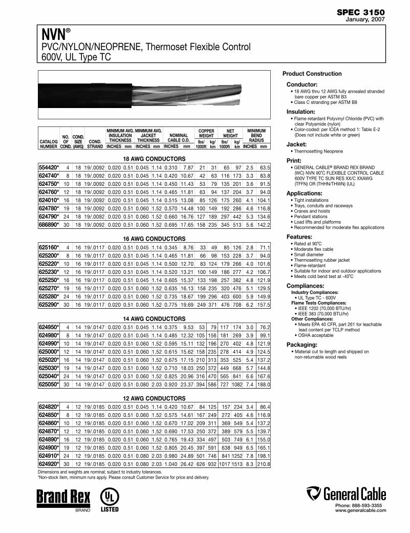
Phone: 888-593-3355www.generalcable.com
SPEC 3150January, 2007
CATALOG NUMBER
NO. OF
COND.
COND.SIZE
(AWG)
MINIMUM AVG. INSULATION THICKNESS
INCHES mm
MINIMUM AVG. JACKET
THICKNESS INCHES mm
MINIMUM BEND
RADIUS INCHES mm
COND.STRAND
COPPER WEIGHT
lbs/ kg/ 1000ft km
NET WEIGHT
lbs/ kg/ 1000ft km
NOMINAL CABLE O.D.
INCHES mm
NVN®
PVC/NYLON/NEOPRENE, Thermoset Flexible Control600V, UL Type TC
Product Construction
Conductor:• 18 AWG thru 12 AWG fully annealed stranded
bare copper per ASTM B3• Class C stranding per ASTM B8
Insulation:• Flame-retardant Polyvinyl Chloride (PVC) with
clear Polyamide (nylon)• Color-coded: per ICEA method 1: Table E-2
(Does not include white or green)
Jacket:• Thermosetting Neoprene
Print: • GENERAL CABLE® BRAND REX BRAND
(WC) NVN 90˚C FLEXIBLE CONTROL CABLE 600V TYPE TC SUN RES XX/C XXAWG (TFFN) OR (THHN/THWN) (UL)
Applications: • Tight installations• Trays, conduits and raceways• Cranes and hoists• Pendant stations• Load lifts and platforms• Recommended for moderate flex applications
Features:• Rated at 90˚C• Moderate flex cable• Small diameter• Thermosetting rubber jacket• Flame-retardant• Suitable for indoor and outdoor applications• Meets cold bend test at -40˚C
Compliances:Industry Compliances: • UL Type TC - 600VFlame Tests Compliances: • IEEE 1202 (70,000 BTU/hr) • IEEE 383 (70,000 BTU/hr)Other Compliances: • Meets EPA 40 CFR, part 261 for leachable lead content per TCLP method • OSHA acceptable
Packaging:• Material cut to length and shipped on
non-returnable wood reels
4 18 19/.0092 0.020 0.51 0.045 1.14 0.310 7.87 21 31 65 97 2.5 63.5
8 18 19/.0092 0.020 0.51 0.045 1.14 0.420 10.67 42 63 116 173 3.3 83.8
10 18 19/.0092 0.020 0.51 0.045 1.14 0.450 11.43 53 79 135 201 3.6 91.5
12 18 19/.0092 0.020 0.51 0.045 1.14 0.465 11.81 63 94 137 204 3.7 94.0
16 18 19/.0092 0.020 0.51 0.045 1.14 0.515 13.08 85 126 175 260 4.1 104.1
19 18 19/.0092 0.020 0.51 0.060 1.52 0.570 14.48 100 149 192 286 4.6 116.8
24 18 19/.0092 0.020 0.51 0.060 1.52 0.660 16.76 127 189 297 442 5.3 134.6
30 18 19/.0092 0.020 0.51 0.060 1.52 0.695 17.65 158 235 345 513 5.6 142.2
554420* 624740* 624750* 624760* 624010* 624780* 624790* 686890*
18 AWG CONDUCTORS
4 16 19/.0117 0.020 0.51 0.045 1.14 0.345 8.76 33 49 85 126 2.8 71.1
8 16 19/.0117 0.020 0.51 0.045 1.14 0.465 11.81 66 98 153 228 3.7 94.0
10 16 19/.0117 0.020 0.51 0.045 1.14 0.500 12.70 83 124 179 266 4.0 101.6
12 16 19/.0117 0.020 0.51 0.045 1.14 0.520 13.21 100 149 186 277 4.2 106.7
16 16 19/.0117 0.020 0.51 0.045 1.14 0.605 15.37 133 198 257 382 4.8 121.9
19 16 19/.0117 0.020 0.51 0.060 1.52 0.635 16.13 158 235 320 476 5.1 129.5
24 16 19/.0117 0.020 0.51 0.060 1.52 0.735 18.67 199 296 403 600 5.9 149.9
30 16 19/.0117 0.020 0.51 0.060 1.52 0.775 19.69 249 371 476 708 6.2 157.5
625160* 625200* 625220* 625230* 625250* 625270* 625280* 625290*
16 AWG CONDUCTORS
14 AWG CONDUCTORS 4 14 19/.0147 0.020 0.51 0.045 1.14 0.375 9.53 53 79 117 174 3.0 76.2
8 14 19/.0147 0.020 0.51 0.045 1.14 0.485 12.32 105 156 181 269 3.9 99.1
10 14 19/.0147 0.020 0.51 0.060 1.52 0.595 15.11 132 196 270 402 4.8 121.9
12 14 19/.0147 0.020 0.51 0.060 1.52 0.615 15.62 158 235 278 414 4.9 124.5
16 14 19/.0147 0.020 0.51 0.060 1.52 0.675 17.15 210 313 353 525 5.4 137.2
19 14 19/.0147 0.020 0.51 0.060 1.52 0.710 18.03 250 372 449 668 5.7 144.8
24 14 19/.0147 0.020 0.51 0.060 1.52 0.825 20.96 316 470 565 841 6.6 167.6
30 14 19/.0147 0.020 0.51 0.080 2.03 0.920 23.37 394 586 727 1082 7.4 188.0
624950* 624980* 624990* 625000* 625020* 625030* 625040* 625050*
12 AWG CONDUCTORS 4 12 19/.0185 0.020 0.51 0.045 1.14 0.420 10.67 84 125 157 234 3.4 86.4
8 12 19/.0185 0.020 0.51 0.060 1.52 0.575 14.61 167 249 272 405 4.6 116.9
10 12 19/.0185 0.020 0.51 0.060 1.52 0.670 17.02 209 311 369 549 5.4 137.2
12 12 19/.0185 0.020 0.51 0.060 1.52 0.690 17.53 250 372 389 579 5.5 139.7
16 12 19/.0185 0.020 0.51 0.060 1.52 0.765 19.43 334 497 503 749 6.1 155.0
19 12 19/.0185 0.020 0.51 0.060 1.52 0.805 20.45 397 591 638 949 6.5 165.1
24 12 19/.0185 0.020 0.51 0.080 2.03 0.980 24.89 501 746 841 1252 7.8 198.1
30 12 19/.0185 0.020 0.51 0.080 2.03 1.040 26.42 626 932 1017 1513 8.3 210.8
624820* 624850* 624860* 624870* 624890* 624900* 624910* 624920*Dimensions and weights are nominal; subject to industry tolerances.*Non-stock item, minimum runs apply. Please consult Customer Service for price and delivery.
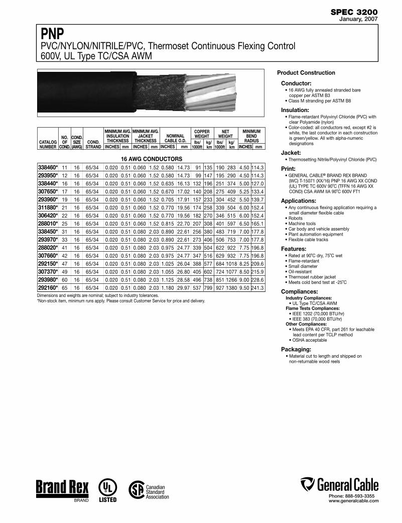
Phone: 888-593-3355www.generalcable.com
16 AWG CONDUCTORS
SPEC 3200January, 2007
CATALOG NUMBER
NO. OF
COND.
MINIMUM AVG. INSULATION THICKNESS
INCHES mm
MINIMUM AVG. JACKET
THICKNESS INCHES mm
MINIMUM BEND
RADIUS INCHES mm
COND.STRAND
COPPER WEIGHT
lbs/ kg/ 1000ft km
NET WEIGHT
lbs/ kg/ 1000ft km
NOMINAL CABLE O.D.
INCHES mm
COND.SIZE
(AWG)
PNPPVC/NYLON/NITRILE/PVC, Thermoset Continuous Flexing Control600V, UL Type TC/CSA AWM
Product Construction
Conductor:• 16 AWG fully annealed stranded bare
copper per ASTM B3• Class M stranding per ASTM B8
Insulation:• Flame-retardant Polyvinyl Chloride (PVC) with
clear Polyamide (nylon)• Color-coded: all conductors red, except #2 is
white, the last conductor in each construction is green/yellow. All with alpha-numeric designations
Jacket:• Thermosetting Nitrile/Polyvinyl Chloride (PVC)
Print: • GENERAL CABLE® BRAND REX BRAND
(WC) T-15071 (XX/16) PNP 16 AWG XX COND (UL) TYPE TC 600V 90˚C (TFFN 16 AWG XX COND) CSA AWM IIA 90˚C 600V FT1
Applications: • Any continuous flexing application requiring a
small diameter flexible cable • Robots• Machine tools• Car body and vehicle assembly• Plant automation equipment• Flexible cable tracks
Features:• Rated at 90˚C dry, 75˚C wet• Flame-retardant• Small diameter • Oil-resistant• Thermoset rubber jacket• Meets cold bend test at -25˚C
Compliances:Industry Compliances: • UL Type TC/CSA AWM Flame Tests Compliances: • IEEE 1202 (70,000 BTU/hr) • IEEE 383 (70,000 BTU/hr)Other Compliances: • Meets EPA 40 CFR, part 261 for leachable lead content per TCLP method • OSHA acceptable
Packaging:• Material cut to length and shipped on
non-returnable wood reels
11 16 65/34 0.020 0.51 0.060 1.52 0.580 14.73 91 135 190 283 4.50 114.3
12 16 65/34 0.020 0.51 0.060 1.52 0.580 14.73 99 147 195 290 4.50 114.3
16 16 65/34 0.020 0.51 0.060 1.52 0.635 16.13 132 196 251 374 5.00 127.0
17 16 65/34 0.020 0.51 0.060 1.52 0.670 17.02 140 208 275 409 5.25 133.4
19 16 65/34 0.020 0.51 0.060 1.52 0.705 17.91 157 233 304 452 5.50 139.7
21 16 65/34 0.020 0.51 0.060 1.52 0.770 19.56 174 258 339 504 6.00 152.4
22 16 65/34 0.020 0.51 0.060 1.52 0.770 19.56 182 270 346 515 6.00 152.4
25 16 65/34 0.020 0.51 0.060 1.52 0.815 22.70 207 308 401 597 6.50 165.1
31 16 65/34 0.020 0.51 0.080 2.03 0.890 22.61 256 380 483 719 7.00 177.8
33 16 65/34 0.020 0.51 0.080 2.03 0.890 22.61 273 406 506 753 7.00 177.8
41 16 65/34 0.020 0.51 0.080 2.03 0.975 24.77 339 504 622 922 7.75 196.8
42 16 65/34 0.020 0.51 0.080 2.03 0.975 24.77 347 516 629 932 7.75 196.8
47 16 65/34 0.020 0.51 0.080 2.03 1.025 26.04 388 577 684 1018 8.25 209.6
49 16 65/34 0.020 0.51 0.080 2.03 1.055 26.80 405 602 724 1077 8.50 215.9
60 16 65/34 0.020 0.51 0.080 2.03 1.125 28.58 496 738 851 1266 9.00 228.6
65 16 65/34 0.020 0.51 0.080 2.03 1.180 29.97 537 799 927 1380 9.50 241.3
338460*293950*338440*307650*293960*311880*306420*288010*338450*293970*288020*307660*292150*307370*293980*292160*
Dimensions and weights are nominal; subject to industry tolerances.*Non-stock item, minimum runs apply. Please consult Customer Service for price and delivery.

Phone: 888-593-3355www.generalcable.com
SPEC 3250January, 2007
CATALOG NUMBER
NO. OF
COND.
MINIMUM AVG. INSULATION THICKNESS
INCHES mm
MINIMUM AVG. JACKET
THICKNESS INCHES mm
MINIMUM BEND
RADIUS INCHES mm
COND.STRAND
COPPER WEIGHT
lbs/ kg/ 1000ft km
NET WEIGHT
lbs/ kg/ 1000ft km
NOMINAL CABLE O.D.
INCHES mm
Product Construction
Conductor:• 18 AWG thru 10 AWG fully annealed stranded
bare copper per ASTM B3• Class M-18 AWG thru 16 AWG• Class K-14 AWG thru 10 AWG• Stranding per ASTM B8
Insulation:• Flame-retardant Polyvinyl Chloride (PVC) with
clear Polyamide (nylon)• Color-coded: all conductors red, except #2 is
white and #3 is green. All with alpha-numeric designations
Jacket:• Heat-, moisture- and oil-resistant Polyvinyl
Chloride (PVC)
Print: • GENERAL CABLE® BRAND REX BRAND
(WC) TYPE MTW FLEXING 600V (UL) NO OF COND/AWG SIZE/CSA AWM IIA 90˚C 600V FT1
Applications: • Pendant cable• Machine tool• Internal machine connections• Material handling equipment• Moderate flex
Features:• Rated at 90˚C• Moisture- and oil-resistant• Heavy-duty PVC jacket• Meets cold bend test at -25˚C
Compliances:Industry Compliances: • UL Type MTW/CSA AWMOther Compliances: • Meets EPA 40 CFR, part 261 for leachable lead content per TCLP method • OSHA acceptable • RoHS compliant
Packaging:• Material cut to length and shipped on
non-returnable wood reels
6 18 41/34 0.020 0.51 0.045 1.14 0.400 10.16 32 48 88 131 3.0 76.2
8 18 41/34 0.020 0.51 0.045 1.14 0.455 11.56 42 63 108 161 3.5 88.9
12 18 41/34 0.020 0.51 0.045 1.14 0.500 12.70 63 94 144 214 4.0 101.6
16 18 41/34 0.020 0.51 0.060 1.52 0.580 14.73 84 125 196 292 4.5 114.3
22 18 41/34 0.020 0.51 0.060 1.52 0.660 16.76 116 173 252 375 5.0 127.0
31 18 41/34 0.020 0.51 0.060 1.52 0.760 19.30 163 243 325 484 6.0 152.4
41 18 41/34 0.020 0.51 0.080 2.03 0.890 22.61 216 321 460 685 7.0 177.8
60 18 41/34 0.020 0.51 0.080 2.03 1.010 25.65 316 470 617 918 8.0 203.2
339170*339180*339190*339200*339210*339220*339230*339240*
18 AWG CONDUCTORS
6 16 65/34 0.020 0.51 0.045 1.14 0.440 11.18 50 74 113 168 3.5 88.9
8 16 65/34 0.020 0.51 0.045 1.14 0.500 12.70 66 98 141 210 4.0 101.6
12 16 65/34 0.020 0.51 0.060 1.52 0.585 14.86 99 147 214 318 4.5 114.3
16 16 65/34 0.020 0.51 0.060 1.52 0.640 16.26 132 196 263 391 5.0 127.0
22 16 65/34 0.020 0.51 0.060 1.52 0.735 18.67 182 271 377 561 5.5 139.7
31 16 65/34 0.020 0.51 0.060 1.52 0.845 21.46 256 381 518 771 6.5 165.1
41 16 65/34 0.020 0.51 0.080 2.03 0.995 25.27 339 504 652 970 8.0 203.2
60 16 65/34 0.020 0.51 0.080 2.03 1.125 28.58 496 738 909 1353 9.0 228.2
339250*339260*339270*339280*339290*339300*339310*339320*
16 AWG CONDUCTORS
14 AWG CONDUCTORS 6 14 41/30 0.020 0.51 0.045 1.14 0.470 11.94 80 119 149 222 3.5 88.9
8 14 41/30 0.020 0.51 0.060 1.52 0.570 14.48 107 159 204 304 4.5 114.3
12 14 41/30 0.020 0.51 0.060 1.52 0.630 16.00 160 238 279 415 5.0 127.0
16 14 41/30 0.020 0.51 0.060 1.52 0.690 17.53 213 317 354 527 5.5 139.7
22 14 41/30 0.020 0.51 0.060 1.52 0.795 20.19 293 436 467 695 6.0 152.4
339330*339340*339350*339360*339370*
12 AWG CONDUCTORS 6 12 65/30 0.020 0.51 0.060 1.52 0.565 14.35 129 192 226 336 4.5 114.3
8 12 65/30 0.020 0.51 0.060 1.52 0.645 16.38 172 256 289 430 5.0 127.0
12 12 65/30 0.020 0.51 0.060 1.52 0.715 18.16 258 384 398 592 5.5 139.7
16 12 65/30 0.020 0.51 0.060 1.52 0.790 20.07 344 512 506 753 6.0 152.4
22 12 65/30 0.020 0.51 0.080 2.03 0.955 24.26 473 704 720 1072 7.5 190.0
339380*339390*339400*339410*339420*
10 AWG CONDUCTORS 6 10 105/30 0.026 0.66 0.060 1.52 0.665 16.89 205 305 329 490 5.0 127.0
8 10 105/30 0.026 0.66 0.060 1.52 0.765 19.43 274 408 424 631 6.0 152.4
12 10 105/30 0.026 0.66 0.080 2.03 0.895 22.73 411 612 604 899 7.0 177.8
16 10 105/30 0.026 0.66 0.080 2.03 1.155 29.34 548 816 852 1268 9.0 228.6
339430*339440*339450*339460*
COND.SIZE
(AWG)
Dimensions and weights are nominal; subject to industry tolerances.*Non-stock item, minimum runs apply. Please consult Customer Service for price and delivery.
MTWPVC/NYLON/PVC, Thermoplastic Flexible Control600V, UL Type MTW/CSA AWM
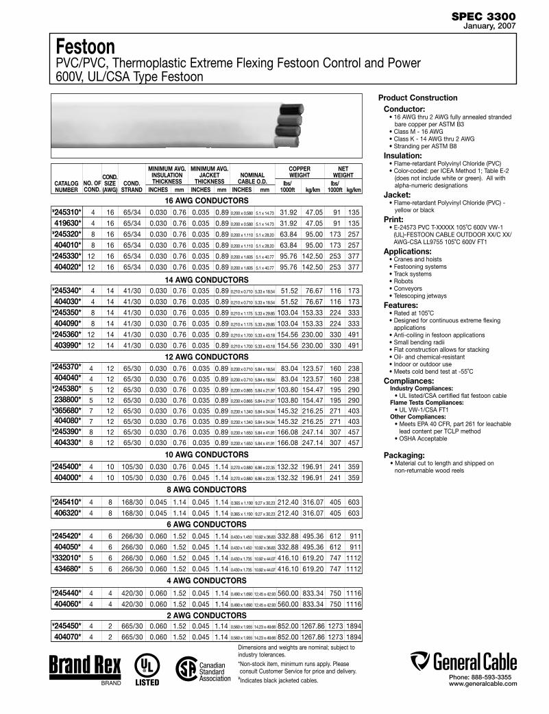
Phone: 888-593-3355www.generalcable.com
SPEC 3300January, 2007
4 12 65/30 0.030 0.76 0.035 0.89 83.04 123.57 160 238
4 12 65/30 0.030 0.76 0.035 0.89 83.04 123.57 160 238
5 12 65/30 0.030 0.76 0.035 0.89 103.80 154.47 195 290
5 12 65/30 0.030 0.76 0.035 0.89 103.80 154.47 195 290
7 12 65/30 0.030 0.76 0.035 0.89 145.32 216.25 271 403
7 12 65/30 0.030 0.76 0.035 0.89 145.32 216.25 271 403
8 12 65/30 0.030 0.76 0.035 0.89 166.08 247.14 307 457
8 12 65/30 0.030 0.76 0.035 0.89 166.08 247.14 307 457
4 16 65/34 0.030 0.76 0.035 0.89 31.92 47.05 91 135
4 16 65/34 0.030 0.76 0.035 0.89 31.92 47.05 91 135
8 16 65/34 0.030 0.76 0.035 0.89 63.84 95.00 173 257
8 16 65/34 0.030 0.76 0.035 0.89 63.84 95.00 173 257
12 16 65/34 0.030 0.76 0.035 0.89 95.76 142.50 253 377
12 16 65/34 0.030 0.76 0.035 0.89 95.76 142.50 253 377
¥245310* 419630*¥245320* 404010*¥245330* 404020*
16 AWG CONDUCTORS
CATALOG NUMBER
NO. OF COND.
MINIMUM AVG. INSULATION THICKNESS
INCHES mm
MINIMUM AVG. JACKET
THICKNESS INCHES mm
NOMINAL CABLE O.D.
INCHES mm
COND.STRAND
COPPER WEIGHT
lbs/ 1000ft kg/km
NET WEIGHT
lbs/ 1000ft kg/km
COND.SIZE
(AWG)
4 14 41/30 0.030 0.76 0.035 0.89 51.52 76.67 116 173
4 14 41/30 0.030 0.76 0.035 0.89 51.52 76.67 116 173
8 14 41/30 0.030 0.76 0.035 0.89 103.04 153.33 224 333
8 14 41/30 0.030 0.76 0.035 0.89 103.04 153.33 224 333
12 14 41/30 0.030 0.76 0.035 0.89 154.56 230.00 330 491
12 14 41/30 0.030 0.76 0.035 0.89 154.56 230.00 330 491
¥245340* 404030*¥245350* 404090*¥245360* 403990*
14 AWG CONDUCTORS
12 AWG CONDUCTORS
FestoonPVC/PVC, Thermoplastic Extreme Flexing Festoon Control and Power600V, UL/CSA Type Festoon
Product ConstructionConductor:
• 16 AWG thru 2 AWG fully annealed stranded bare copper per ASTM B3
• Class M - 16 AWG• Class K - 14 AWG thru 2 AWG• Stranding per ASTM B8
Insulation:• Flame-retardant Polyvinyl Chloride (PVC)• Color-coded: per ICEA Method 1; Table E-2
(does not include white or green). All with alpha-numeric designations
Jacket:• Flame-retardant Polyvinyl Chloride (PVC) -
yellow or black
Print:• E-24573 PVC T-XXXXX 105˚C 600V VW-1
(UL)-FESTOON CABLE OUTDOOR XX/C XX/AWG-CSA LL9755 105˚C 600V FT1
Applications:• Cranes and hoists• Festooning systems• Track systems• Robots• Conveyors• Telescoping jetways
Features:• Rated at 105˚C• Designed for continuous extreme flexing
applications• Anti-coiling in festoon applications• Small bending radii• Flat construction allows for stacking• Oil- and chemical-resistant• Indoor or outdoor use• Meets cold bend test at -55˚C
Compliances:Industry Compliances: • UL listed/CSA certified flat festoon cableFlame Tests Compliances: • UL VW-1/CSA FT1Other Compliances: • Meets EPA 40 CFR, part 261 for leachable lead content per TCLP method • OSHA Acceptable
Packaging:• Material cut to length and shipped on
non-returnable wood reels 4 10 105/30 0.030 0.76 0.045 1.14 132.32 196.91 241 359
4 10 105/30 0.030 0.76 0.045 1.14 132.32 196.91 241 359
¥245400* 404000*
10 AWG CONDUCTORS
4 8 168/30 0.045 1.14 0.045 1.14 212.40 316.07 405 603
4 8 168/30 0.045 1.14 0.045 1.14 212.40 316.07 405 603
¥245410* 406320*
8 AWG CONDUCTORS
4 4 420/30 0.060 1.52 0.045 1.14 560.00 833.34 750 1116
4 4 420/30 0.060 1.52 0.045 1.14 560.00 833.34 750 1116
¥245440* 404060*
4 AWG CONDUCTORS
4 2 665/30 0.060 1.52 0.045 1.14 852.00 1267.86 1273 1894
4 2 665/30 0.060 1.52 0.045 1.14 852.00 1267.86 1273 1894
¥245450* 404070*
2 AWG CONDUCTORS
4 6 266/30 0.060 1.52 0.045 1.14 332.88 495.36 612 911
4 6 266/30 0.060 1.52 0.045 1.14 332.88 495.36 612 911
5 6 266/30 0.060 1.52 0.045 1.14 416.10 619.20 747 1112
5 6 266/30 0.060 1.52 0.045 1.14 416.10 619.20 747 1112
¥245420* 404050*¥332010* 434680*
6 AWG CONDUCTORS
Dimensions and weights are nominal; subject to industry tolerances.*Non-stock item, minimum runs apply. Please consult Customer Service for price and delivery.
¥Indicates black jacketed cables.
0.210 x 0.710 5.33 x 18.54
0.210 x 1.175 5.33 x 29.85
0.210 x 1.700 5.33 x 43.18
0.210 x 0.710 5.33 x 18.54
0.210 x 1.175 5.33 x 29.85
0.210 x 1.700 5.33 x 43.18
0.270 x 0.880 6.86 x 22.35
0.270 x 0.880 6.86 x 22.35
0.365 x 1.190 9.27 x 30.23
0.365 x 1.190 9.27 x 30.23
0.490 x 1.690 12.45 x 42.93
0.490 x 1.690 12.45 x 42.93
0.560 x 1.955 14.23 x 49.66
0.560 x 1.955 14.23 x 49.66
0.430 x 1.450 10.92 x 36.83
0.430 x 1.735 10.92 x 44.07
0.430 x 1.450 10.92 x 36.83
0.430 x 1.735 10.92 x 44.07
0.230 x 0.710 5.84 x 18.54
0.230 x 1.340 5.84 x 34.04
0.230 x 1.650 5.84 x 41.91
0.230 x 0.865 5.84 x 21.97
0.230 x 0.710 5.84 x 18.54
0.230 x 1.340 5.84 x 34.04
0.230 x 1.650 5.84 x 41.91
0.230 x 0.865 5.84 x 21.97
¥245370* 404040*¥245380* 238800*¥365680* 404080*¥245390* 404330*
0.200 x 0.580 5.1 x 14.73
0.200 x 1.110 5.1 x 28.20
0.200 x 1.110 5.1 x 28.20
0.200 x 1.605 5.1 x 40.77
0.200 x 1.605 5.1 x 40.77
0.200 x 0.580 5.1 x 14.73

Phone: 888-593-3355www.generalcable.com
Date of Issue 02/07Industrial Cables Section 4
600V Multi Conductor Control and Power Cables
SPECIFICATION # PRODUCT DESCRIPTION REVISION DATE
4050† CHTC® XLPE/HYP, Control, Unshielded Jan. 2007 600V, UL Type TC—E-2 Color Code
4075† CHTC® XLPE/HYP, Control, Unshielded Jan. 2007 600V, UL Type TC—E-1 Color Code
4100 CHTC® XLPE/HYP, Low-Voltage Power, Unshielded Jan. 2007 600V, UL Type TC-ER1—Method 4 Color Code
4150 EHTC® FR-EPR/HYP, Control, Unshielded Jan. 2007 600V, UL Type TC (18 AWG/16 AWG)—E-2 Color Code
4200 EHTC® FR-EPR/HYP, Control, Unshielded Jan. 2007 600V, UL Type TC (14 AWG—10 AWG)—E-2 Color Code
4250 EHTC® FR-EPR/HYP, Low-Voltage Power, Unshielded Jan. 2007 600V, UL Type TC-ER1—Method 4 Color Code
4300† FREP® FR-EPR/CPE, Control, Unshielded Jan. 2007 600V, UL Type TC-ER1—E-2 Color Code
4310† FREP® FR-EPR/CPE, Control, Unshielded Jan. 2007 600V, UL Type TC-ER1—E-1 Color Code
4325† FREP® FR-EPR/CPE, Control, Shielded Jan. 2007 600V, UL Type TC-ER1, Overall Shielded—E-2 Color Code
4350† FREP® FR-EPR/CPE, Low-Voltage Power, Unshielded Jan. 2007 600V, UL Type TC-ER1—Method 4 Color Code
4400 Arctic-Flex® XLPE/ARCTIC-PVC, Control, Unshielded Jan. 2007 600V, UL Type TC-ER1, CSA Type RW90 XLPE, CSA TYPE TC
4450 Arctic-Flex® XLPE/ARCTIC-PVC, Low-Voltage Power, Unshielded Jan. 2007 600V, UL Type TC-ER1, CSA Type RW90 XLPE, CSA TYPE TC
4500† CVTC® XLPE/PVC, Control, Unshielded Jan. 2007 600V, UL Type TC-ER1—E-2 Color Code
4550† CVTC® XLPE/PVC, Low-Voltage Power, Unshielded Jan. 2007 600V, UL Type TC-ER1—Method 4 Color Code
4575 CVTC® VFD XLPE/PVC, Low-Voltage Power, Shielded Jan. 2007 2000V, UL Type TC-ER1—Method 4 Color Code
4600† VNTC® PVC/NYLON/PVC, Control, Unshielded Jan. 2007 600V, UL Type TC-ER1 (18 AWG/16 AWG)—E-2 Color Code
4650† VNTC® PVC/NYLON/PVC, Control, Unshielded Jan. 2007 600V, UL Type TC-ER1 (14 AWG—10 AWG)—E-2 Color Code
4700† VNTC® PVC/NYLON/PVC, Control, Shielded Jan. 2007 600V, UL Type TC-ER1, Overall Shielded—E-2 Color Code
4750† VNTC® PVC/NYLON/PVC, Low-Voltage Power, Unshielded Jan. 2007 600V, UL Type TC-ER1—Method 4 Color Code
4800 20/10 PE/PVC/PVC, Control, Unshielded Jan. 2007 600V (18 AWG/16 AWG)—E-1 Color Code
4850 20/10 PE/PVC/PVC, Control, Unshielded Jan. 2007 600V (14 AWG—10 AWG)—E-1 Color Code
†Indicates these products are stocked by General Cable
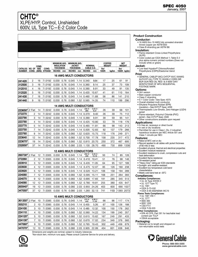
Phone: 888-593-3355www.generalcable.com
SPEC 4050January, 2007
2 Flat 14 7/.0242 0.030 0.76 0.045 1.14 26 39 68 101
2 14 7/.0242 0.030 0.76 0.045 1.14 0.370 9.40 26 39 75 112
3 14 7/.0242 0.030 0.76 0.045 1.14 0.390 9.91 39 59 95 141
4 14 7/.0242 0.030 0.76 0.045 1.14 0.425 10.80 53 78 118 176
5 14 7/.0242 0.030 0.76 0.045 1.14 0.465 11.81 66 98 143 213
7 14 7/.0242 0.030 0.76 0.045 1.14 0.505 12.83 92 137 179 266
9 14 7/.0242 0.030 0.76 0.060 1.52 0.620 15.75 118 176 249 371
12 14 7/.0242 0.030 0.76 0.060 1.52 0.700 17.78 158 235 317 472
19 14 7/.0242 0.030 0.76 0.060 1.52 0.815 20.70 250 372 467 695
37 14 7/.0242 0.030 0.76 0.080 2.03 1.130 28.70 490 730 899 1338
223650* 272270 223790 223780 223770 223750 223760 223640 223670* 232850*
Product ConstructionConductor:
• 16 AWG thru 10 AWG fully annealed stranded tinned copper per ASTM B33
• Class B stranding per ASTM B8Insulation:
• Flame-retardant Cross-Linked Polyethylene (XLPE)
• Color-coded per ICEA Method 1; Table E-2 plus alpha-numeric printed numbers (Does not include white or green)
Jacket:• Low-lead Hypalon® Chlorosulfonated
Polyethylene (CSPE)/Elastomer blendPrint
• GENERAL CABLE® (WC) CHTC® XX/C XXAWG XLP/HYP (UL) TYPE TC XHHW-2 CDRS DIR BUR SUN RES OIL RES I & II 600V DAY/MONTH/YEAR OF MFG SEQUENTIAL FOOTAGE MARK
Options:• 2kV version• Bare copper conductor• Class C stranding• E-1 Color Code—See Spec 4075• Overall shielded multi conductor• Ethylene Propylene Rubber (EPR)
insulation—See EHTC® Spec 4200• Thermoplastic Low-Smoke, Zero-Halogen (LSZH)
jacket• Flame-retardant, Polyvinyl Chloride (PVC)
jacket—See CVTC® Spec 4500• Other constructions available upon request
Applications:• In free air, raceways or direct burial• In wet or dry locations • Permitted for use in Class I, Div. 2 industrial
hazardous locations per NEC Article 501 and Class 1 circuits per NEC
Features:• Rated at 90˚C wet or dry• Ripcord applied to all cables with jacket thickness
of 60 mils or less• Excellent physical, thermal and electrical properties• Excellent moisture resistance• Excellent resistance to crush, compression cuts and
heat deformation• Excellent flame resistance• Oil-resistant jacket• “Heavy Duty” rating per ICEA standards• Sunlight- and weather-resistant• Excellent low temperature cold bend
characteristics• Meets cold bend test at -35˚C
Compliances:Industry Compliances: • UL 44 Type XHHW-2 • UL 1277 Type TC • UL 1581 • ICEA S-73-532 • ICEA S-95-658/NEMA WC70Flame Tests Compliances: • UL 1581 VW-1 • UL 1277 • IEEE 383 • IEEE 1202 • CSA FT-4 • ICEA T-29-520Other Compliances: • EPA 40 CFR, Part 261 for leachable lead
content per TCLP • OSHA acceptable
Packaging:• Material cut to length and shipped on
non-returnable wood reels
12 AWG MULTI CONDUCTORS
14 AWG MULTI CONDUCTORS
2 Flat 12 7/.0305 0.030 0.76 0.045 1.14 50 74 85 126
2 12 7/.0305 0.030 0.76 0.045 1.14 0.410 10.41 51 76 98 146
3 12 7/.0305 0.030 0.76 0.045 1.14 0.435 11.05 64 95 127 189
4 12 7/.0305 0.030 0.76 0.045 1.14 0.475 12.07 85 126 160 238
5 12 7/.0305 0.030 0.76 0.045 1.14 0.520 13.21 106 158 194 289
7 12 7/.0305 0.030 0.76 0.060 1.52 0.595 15.11 168 251 264 393
9 12 7/.0305 0.030 0.76 0.060 1.52 0.695 17.65 191 285 345 513
12 12 7/.0305 0.030 0.76 0.060 1.52 0.780 19.81 255 380 435 647
19 12 7/.0305 0.030 0.76 0.080 2.03 0.955 24.26 403 600 690 1027
37 12 7/.0305 0.030 0.76 0.080 2.03 1.265 32.13 741 1103 1393 2073
10 AWG MULTI CONDUCTORS 2 Flat 10 7/.0385 0.030 0.76 0.045 1.14 66 98 117 174
2 10 7/.0385 0.030 0.76 0.045 1.14 0.455 5.26 67 100 126 188
3 10 7/.0385 0.030 0.76 0.045 1.14 0.485 12.32 100 150 176 262
4 10 7/.0385 0.030 0.76 0.060 1.52 0.560 14.22 134 199 240 357
5 10 7/.0385 0.030 0.76 0.060 1.52 0.615 15.62 167 249 291 433
7 10 7/.0385 0.030 0.76 0.060 1.52 0.670 17.02 234 349 376 560
9 10 7/.0385 0.030 0.76 0.060 1.52 0.765 19.43 302 449 456 679
12 10 7/.0385 0.030 0.76 0.080 2.03 0.905 22.99 404 601 636 946
260730*272260223910 223930 223920 224080 224070 224090 265940*347050*
361350*355210224100 224110224120*224130*347060*347070*
CATALOG NUMBER
NO. OF COND.
MINIMUM AVG. INSULATION THICKNESS
INCHES mm
MINIMUM AVG. JACKET
THICKNESS INCHES mm
NOMINAL CABLE O.D.
INCHES mm
COND.STRAND
COPPER WEIGHT
lbs/ 1000ft kg/km
NET WEIGHT
lbs/ 1000ft kg/km
COND.SIZE
(AWG)
Dimensions and weights are nominal; subject to industry tolerances.*Non-stock item, minimum runs apply. Please consult Customer Service for price and delivery.
.230 X .365
5.84 X 9.27
.250 X .400
6.35 X 10.16
.270 X .445
6.86 X 11.30
CHTC®
XLPE/HYP, Control, Unshielded600V, UL Type TC—E-2 Color Code
2 16 7/.0192 0.030 0.76 0.045 1.14 0.340 8.64 17 25 61 91
3 16 7/.0192 0.030 0.76 0.045 1.14 0.360 9.14 25 37 73 109
4 16 7/.0192 0.030 0.76 0.045 1.14 0.390 9.91 33 49 91 135
5 16 7/.0192 0.030 0.76 0.045 1.14 0.420 10.67 41 61 110 164
7 16 7/.0192 0.030 0.76 0.045 1.14 0.460 11.68 58 86 141 210
9 16 7/.0192 0.030 0.76 0.060 1.52 0.565 14.35 74 110 199 296
241420 312500 312510 312520 241430 241440
16 AWG MULTI CONDUCTORS
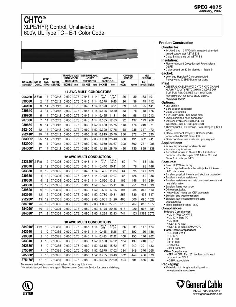
Phone: 888-593-3355www.generalcable.com
SPEC 4075January, 2007
2 Flat 14 7/.0242 0.030 0.76 0.045 1.14 26 39 68 101
2 14 7/.0242 0.030 0.76 0.045 1.14 0.370 9.40 26 39 75 112
3 14 7/.0242 0.030 0.76 0.045 1.14 0.390 9.91 39 59 95 141
4 14 7/.0242 0.030 0.76 0.045 1.14 0.425 10.80 53 78 118 176
5 14 7/.0242 0.030 0.76 0.045 1.14 0.465 11.81 66 98 143 213
7 14 7/.0242 0.030 0.76 0.045 1.14 0.505 12.83 92 137 179 266
9 14 7/.0242 0.030 0.76 0.060 1.52 0.620 15.75 118 176 249 371
12 14 7/.0242 0.030 0.76 0.060 1.52 0.700 17.78 158 235 317 472
19 14 7/.0242 0.030 0.76 0.060 1.52 0.815 20.70 250 372 467 695
25 14 7/.0242 0.030 0.76 0.080 2.03 1.000 25.40 330 491 632 941
30 14 7/.0242 0.030 0.76 0.080 2.03 1.050 26.67 398 592 731 1088
37 14 7/.0242 0.030 0.76 0.080 2.03 1.130 28.70 490 730 899 1338
256260 330580 244160 239640 239700 237500 239660 252400 252410* 383980* 383990* 384000*
Product ConstructionConductor:
• 14 AWG thru 10 AWG fully annealed stranded tinned copper per ASTM B33
• Class B stranding per ASTM B8Insulation:
• Flame-retardant Cross-Linked Polyethylene (XLPE)
• Color-coded per ICEA Method 1; Table E-1Jacket:
• Low-lead Hypalon® Chlorosulfonated Polyethylene (CSPE)/Elastomer blend
Print• GENERAL CABLE® (WC) CHTC® XX/C XXAWG
XLP/HYP (UL) TYPE TC XHHW-2 CDRS DIR BUR SUN RES OIL RES I & II 600V DAY/MONTH/YEAR OF MFG SEQUENTIAL FOOTAGE MARK
Options:• 2kV version• Bare copper conductor• Class C stranding• E-2 Color Code—See Spec 4050• Overall shielded multi conductor• Ethylene Propylene Rubber (EPR)
insulation—See EHTC Spec 4200• Thermoplastic Low-Smoke, Zero-Halogen (LSZH)
jacket• Flame-retardant, Polyvinyl Chloride (PVC)
jacket—See CVTC® Spec 4500• Other constructions available upon request
Applications:• In free air, raceways or direct burial• In wet or dry locations • Permitted for use in Class I, Div. 2 industrial
hazardous locations per NEC Article 501 and Class 1 circuits per NEC
Features:• Rated at 90˚C wet or dry• Ripcord applied to all cables with jacket thickness
of 60 mils or less• Excellent physical, thermal and electrical properties• Excellent moisture resistance• Excellent resistance to crush, compression cuts and
heat deformation• Excellent flame resistance• Oil-resistant jacket• “Heavy Duty” rating per ICEA standards• Sunlight- and weather-resistant• Excellent low temperature cold bend
characteristics• Meets cold bend test at -35˚C
Compliances:Industry Compliances: • UL 44 Type XHHW-2 • UL 1277 Type TC • UL 1581 • ICEA S-73-532 • ICEA S-95-658/NEMA WC70Flame Tests Compliances: • UL 1581 VW-1 • UL 1277 • IEEE 383 • IEEE 1202 • CSA FT-4 • ICEA T-29-520Other Compliances: • EPA 40 CFR, Part 261 for leachable lead
content per TCLP • OSHA acceptable
Packaging:• Material cut to length and shipped on
non-returnable wood reels
12 AWG MULTI CONDUCTORS
14 AWG MULTI CONDUCTORS
2 Flat 12 7/.0305 0.030 0.76 0.045 1.14 50 74 85 126
2 12 7/.0305 0.030 0.76 0.045 1.14 0.410 10.41 51 76 98 146
3 12 7/.0305 0.030 0.76 0.045 1.14 0.435 11.05 64 95 127 189
4 12 7/.0305 0.030 0.76 0.045 1.14 0.475 12.07 85 126 160 238
5 12 7/.0305 0.030 0.76 0.045 1.14 0.520 13.21 106 158 194 289
7 12 7/.0305 0.030 0.76 0.060 1.52 0.595 15.11 168 251 264 393
9 12 7/.0305 0.030 0.76 0.060 1.52 0.695 17.65 191 285 345 513
12 12 7/.0305 0.030 0.76 0.060 1.52 0.780 19.81 255 380 435 647
19 12 7/.0305 0.030 0.76 0.080 2.03 0.955 24.26 403 600 690 1027
25 12 7/.0305 0.030 0.76 0.080 2.03 1.095 27.81 515 767 858 1277
30 12 7/.0305 0.030 0.76 0.080 2.03 1.175 29.85 618 920 997 1484
37 12 7/.0305 0.030 0.76 0.080 2.03 1.265 32.13 741 1103 1393 2073
10 AWG MULTI CONDUCTORS 2 Flat 10 7/.0385 0.030 0.76 0.045 1.14 66 98 117 174
2 10 7/.0385 0.030 0.76 0.045 1.14 0.455 5.26 67 100 126 188
3 10 7/.0385 0.030 0.76 0.045 1.14 0.485 12.32 100 150 176 262
4 10 7/.0385 0.030 0.76 0.060 1.52 0.560 14.22 134 199 240 357
5 10 7/.0385 0.030 0.76 0.060 1.52 0.615 15.62 167 249 291 433
7 10 7/.0385 0.030 0.76 0.060 1.52 0.670 17.02 234 349 376 560
9 10 7/.0385 0.030 0.76 0.060 1.52 0.765 19.43 302 449 456 679
12 10 7/.0385 0.030 0.76 0.080 2.03 0.905 22.99 404 601 636 946
233320*239670233330 239680 239650 243530 239620 252360 252230*384010*384020* 384030*
384040*243540239630 233310262680*375010*235680*375470*
CATALOG NUMBER
NO. OF COND.
MINIMUM AVG. INSULATION THICKNESS
INCHES mm
MINIMUM AVG. JACKET
THICKNESS INCHES mm
NOMINAL CABLE O.D.
INCHES mm
COND.STRAND
COPPER WEIGHT
lbs/ 1000ft kg/km
NET WEIGHT
lbs/ 1000ft kg/km
COND.SIZE
(AWG)
Dimensions and weights are nominal; subject to industry tolerances.*Non-stock item, minimum runs apply. Please consult Customer Service for price and delivery.
.230 X .365
5.84 X 9.27
.250 X .400
6.35 X 10.16
.270 X .445
6.86 X 11.30
CHTC®
XLPE/HYP, Control, Unshielded600V, UL Type TC—E-1 Color Code
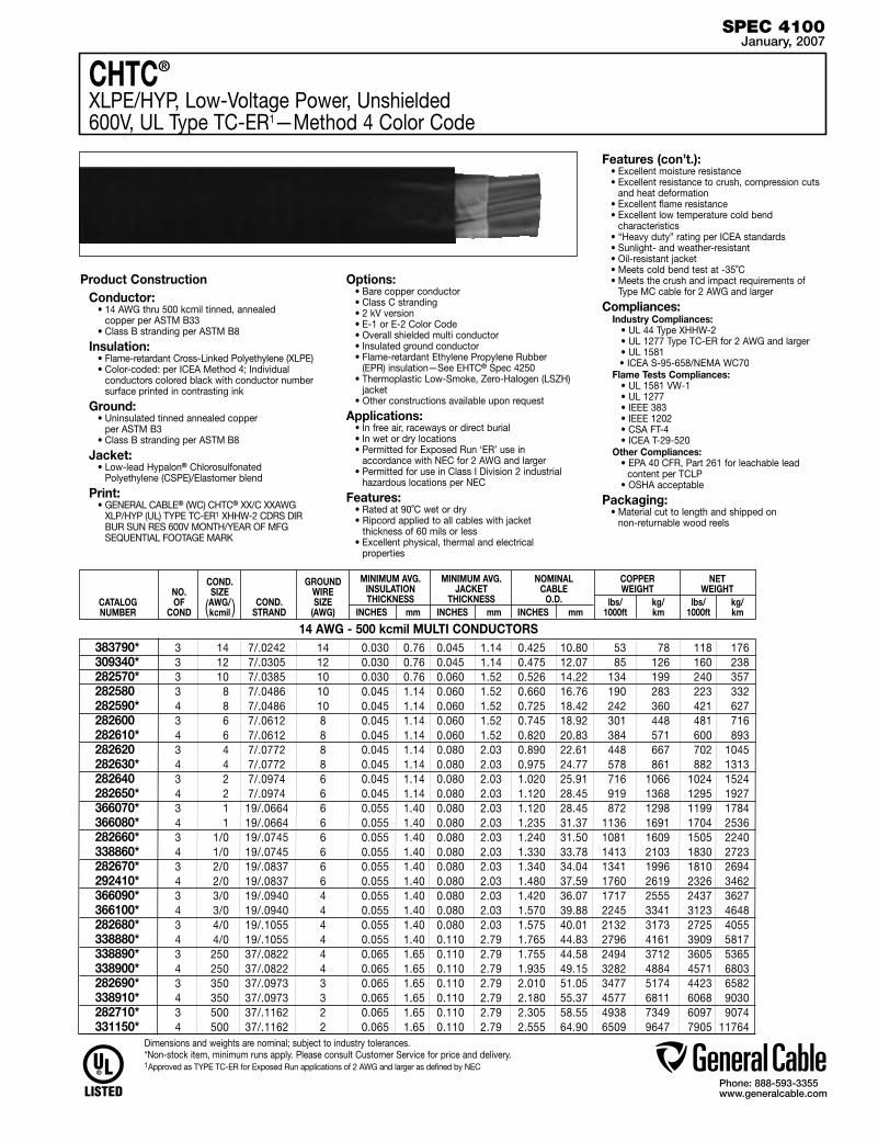
Phone: 888-593-3355www.generalcable.com
SPEC 4100January, 2007
3 14 7/.0242 14 0.030 0.76 0.045 1.14 0.425 10.80 53 78 118 176 3 12 7/.0305 12 0.030 0.76 0.045 1.14 0.475 12.07 85 126 160 238 3 10 7/.0385 10 0.030 0.76 0.060 1.52 0.526 14.22 134 199 240 357 3 8 7/.0486 10 0.045 1.14 0.060 1.52 0.660 16.76 190 283 223 332 4 8 7/.0486 10 0.045 1.14 0.060 1.52 0.725 18.42 242 360 421 627 3 6 7/.0612 8 0.045 1.14 0.060 1.52 0.745 18.92 301 448 481 716 4 6 7/.0612 8 0.045 1.14 0.060 1.52 0.820 20.83 384 571 600 893 3 4 7/.0772 8 0.045 1.14 0.080 2.03 0.890 22.61 448 667 702 1045 4 4 7/.0772 8 0.045 1.14 0.080 2.03 0.975 24.77 578 861 882 1313 3 2 7/.0974 6 0.045 1.14 0.080 2.03 1.020 25.91 716 1066 1024 1524 4 2 7/.0974 6 0.045 1.14 0.080 2.03 1.120 28.45 919 1368 1295 1927 3 1 19/.0664 6 0.055 1.40 0.080 2.03 1.120 28.45 872 1298 1199 1784 4 1 19/.0664 6 0.055 1.40 0.080 2.03 1.235 31.37 1136 1691 1704 2536 3 1/0 19/.0745 6 0.055 1.40 0.080 2.03 1.240 31.50 1081 1609 1505 2240 4 1/0 19/.0745 6 0.055 1.40 0.080 2.03 1.330 33.78 1413 2103 1830 2723 3 2/0 19/.0837 6 0.055 1.40 0.080 2.03 1.340 34.04 1341 1996 1810 2694 4 2/0 19/.0837 6 0.055 1.40 0.080 2.03 1.480 37.59 1760 2619 2326 3462 3 3/0 19/.0940 4 0.055 1.40 0.080 2.03 1.420 36.07 1717 2555 2437 3627 4 3/0 19/.0940 4 0.055 1.40 0.080 2.03 1.570 39.88 2245 3341 3123 4648 3 4/0 19/.1055 4 0.055 1.40 0.080 2.03 1.575 40.01 2132 3173 2725 4055 4 4/0 19/.1055 4 0.055 1.40 0.110 2.79 1.765 44.83 2796 4161 3909 5817 3 250 37/.0822 4 0.065 1.65 0.110 2.79 1.755 44.58 2494 3712 3605 5365 4 250 37/.0822 4 0.065 1.65 0.110 2.79 1.935 49.15 3282 4884 4571 6803 3 350 37/.0973 3 0.065 1.65 0.110 2.79 2.010 51.05 3477 5174 4423 6582 4 350 37/.0973 3 0.065 1.65 0.110 2.79 2.180 55.37 4577 6811 6068 9030 3 500 37/.1162 2 0.065 1.65 0.110 2.79 2.305 58.55 4938 7349 6097 9074 4 500 37/.1162 2 0.065 1.65 0.110 2.79 2.555 64.90 6509 9647 7905 11764
Product ConstructionConductor:
• 14 AWG thru 500 kcmil tinned, annealed copper per ASTM B33
• Class B stranding per ASTM B8
Insulation:• Flame-retardant Cross-Linked Polyethylene (XLPE)• Color-coded: per ICEA Method 4; Individual
conductors colored black with conductor number surface printed in contrasting ink
Ground:• Uninsulated tinned annealed copper
per ASTM B3• Class B stranding per ASTM B8
Jacket:• Low-lead Hypalon® Chlorosulfonated
Polyethylene (CSPE)/Elastomer blend
Print:• GENERAL CABLE® (WC) CHTC® XX/C XXAWG
XLP/HYP (UL) TYPE TC-ER1 XHHW-2 CDRS DIR BUR SUN RES 600V MONTH/YEAR OF MFG SEQUENTIAL FOOTAGE MARK
Options:• Bare copper conductor• Class C stranding• 2 kV version• E-1 or E-2 Color Code • Overall shielded multi conductor • Insulated ground conductor• Flame-retardant Ethylene Propylene Rubber
(EPR) insulation—See EHTC® Spec 4250• Thermoplastic Low-Smoke, Zero-Halogen (LSZH)
jacket• Other constructions available upon request
Applications: • In free air, raceways or direct burial • In wet or dry locations• Permitted for Exposed Run ‘ER’ use in
accordance with NEC for 2 AWG and larger• Permitted for use in Class I Division 2 industrial
hazardous locations per NEC
Features:• Rated at 90˚C wet or dry• Ripcord applied to all cables with jacket
thickness of 60 mils or less• Excellent physical, thermal and electrical
properties
Features (con’t.):• Excellent moisture resistance• Excellent resistance to crush, compression cuts
and heat deformation• Excellent flame resistance• Excellent low temperature cold bend
characteristics• “Heavy duty” rating per ICEA standards• Sunlight- and weather-resistant• Oil-resistant jacket• Meets cold bend test at -35˚C• Meets the crush and impact requirements of
Type MC cable for 2 AWG and larger
Compliances:Industry Compliances: • UL 44 Type XHHW-2 • UL 1277 Type TC-ER for 2 AWG and larger • UL 1581 • ICEA S-95-658/NEMA WC70Flame Tests Compliances: • UL 1581 VW-1 • UL 1277 • IEEE 383 • IEEE 1202 • CSA FT-4 • ICEA T-29-520Other Compliances: • EPA 40 CFR, Part 261 for leachable lead
content per TCLP • OSHA acceptable
Packaging:• Material cut to length and shipped on
non-returnable wood reels
CHTC®
XLPE/HYP, Low-Voltage Power, Unshielded600V, UL Type TC-ER1—Method 4 Color Code
383790*309340*282570*282580282590*282600 282610*282620282630*282640282650*366070*366080*282660*338860*282670*292410*366090*366100*282680*338880*338890*338900*282690*338910*282710*331150*
14 AWG - 500 kcmil MULTI CONDUCTORS
CATALOG NUMBER
NO.OF
COND
COND.SIZE AWG/kcmil
MINIMUM AVG. INSULATION THICKNESS
INCHES mm
MINIMUM AVG. JACKET
THICKNESS INCHES mm
NOMINAL CABLE
O.D. INCHES mm
COPPER WEIGHT
lbs/ kg/ 1000ft km
NET WEIGHT
lbs/ kg/ 1000ft km
COND.STRAND
GROUNDWIRESIZE
(AWG)
Dimensions and weights are nominal; subject to industry tolerances.*Non-stock item, minimum runs apply. Please consult Customer Service for price and delivery.1Approved as TYPE TC-ER for Exposed Run applications of 2 AWG and larger as defined by NEC
( )

Phone: 888-593-3355www.generalcable.com
SPEC 4150January, 2007
EHTC®
FR-EPR/HYP, Control, Unshielded600V, UL Type TC (18 AWG/16 AWG)—E-2 Color Code
Product ConstructionConductor:
• 18 AWG and 16 AWG tinned, annealed copper per ASTM B33
• Class B stranding per ASTM B8
Insulation:• Flame-retardant Ethylene Propylene Rubber
(FR-EPR) Type II• Color-coded per ICEA Method 1; Table E-2
(does not include white or green)
Jacket:• Low-lead Hypalon Chlorosulfonated
Polyethylene (CSPE)/Elastomer blend
Print• GENERAL CABLE® (WC) EHTC® XX/C
XXAWG EPR/HYP UL TYPE TC 90˚ WET OR DRY CDRS BUR SUN RES 600V, DAY/MONTH/YEAR OF MFG SEQUENTIAL FOOTAGE MARK
Options:• 2kV version• Bare copper conductors• Class C stranding• Insulated or uninsulated ground conductors• Overall shielded multi conductors• Duralox® aluminum interlocked armor• E-1 Color Code• Flame-retardant Polyvinyl Chloride (PVC) jacket • Thermoplastic Low-Smoke, Zero-Halogen
(LSZH) jacket• Flame-retardant Thermoplastic Chloronated
Polyethylene (CPE)—See FREP® Spec 4300• Other constructions available upon request
Applications:• In free air, raceways or direct burial• In wet or dry locations• At temperature as low as -35˚C• In Class I Division 2 industrial hazardous
locations per NEC
Features:• Rated at 90˚C wet or dry• Ripcord applied to all cables with jacket
thickness of 60 mils or less• Excellent physical, thermal and electrical
properties• Excellent moisture resistance• Excellent resistance to crush, compression
cuts and heat deformation• Excellent flame resistance• Excellent low temperature cold bend
characteristics• Good abrasion resistance• Low moisture absorption characteristics• “Heavy duty” rated per ICEA standards• Meets cold bend test at -35˚C
Compliances:Industry Compliances: • UL 1277 Type TC • UL 1581 • ICEA S-73-532 • ICEA S-95-658/NEMA WC70Flame Tests Compliances: • UL 1581 VW-1 • UL 1277 • IEEE 383 • IEEE 1202 • CSA FT-4 • ICEA T-29-520Other Compliances: • EPA 40 CFR, Part 261 for leachable lead
content per TCLP • OSHA acceptable
Packaging:• Material cut to length and shipped on
non-returnable wood reels
CATALOG NUMBER
NO. OF COND.
MINIMUM AVG. INSULATION THICKNESS
INCHES mm
MINIMUM AVG. JACKET
THICKNESS INCHES mm
NOMINAL CABLE O.D.
INCHES mm
COND.STRAND
COPPER WEIGHT
lbs/ 1000ft kg/km
NET WEIGHT
lbs/ 1000ft kg/km
COND.SIZE
(AWG)
18 AWG MULTI CONDUCTORS
2 Flat 18 7/.0152 0.025 0.64 0.045 1.14 10 15 37 55
2 18 7/.0152 0.025 0.64 0.045 1.14 0.295 7.49 10 15 45 67
3 18 7/.0152 0.025 0.64 0.045 1.14 0.310 7.88 15 23 55 82
4 18 7/.0152 0.025 0.64 0.045 1.14 0.340 8.64 20 30 67 100
5 18 7/.0152 0.025 0.64 0.045 1.14 0.365 9.27 26 38 79 118
7 18 7/.0152 0.025 0.64 0.045 1.14 0.395 10.03 36 53 97 144
9 18 7/.0152 0.025 0.64 0.045 1.14 0.455 11.56 46 69 123 183
10 18 7/.0152 0.025 0.64 0.045 1.14 0.485 12.32 51 76 137 204
12 18 7/.0152 0.025 0.64 0.045 1.14 0.510 12.95 61 91 153 228
15 18 7/.0152 0.025 0.64 0.060 1.52 0.580 14.73 77 114 202 301
19 18 7/.0152 0.025 0.64 0.060 1.52 0.625 15.88 97 144 243 362
25 18 7/.0152 0.025 0.64 0.060 1.52 0.720 18.29 128 190 301 448
30 18 7/.0152 0.025 0.64 0.060 1.52 0.770 19.56 154 229 345 513
37 18 7/.0152 0.025 0.64 0.060 1.52 0.830 21.08 189 281 414 616
16 AWG MULTI CONDUCTORS 2 Flat 16 7/.0192 0.025 0.64 0.045 1.14 16 24 46 68
2 16 7/.0192 0.025 0.64 0.045 1.14 0.320 8.13 16 24 55 82
3 16 7/.0192 0.025 0.64 0.045 1.14 0.340 8.67 24 36 69 103
4 16 7/.0192 0.025 0.64 0.045 1.14 0.365 9.27 32 48 85 126
5 16 7/.0192 0.025 0.64 0.045 1.14 0.400 10.20 40 60 102 152
7 16 7/.0192 0.025 0.64 0.045 1.14 0.430 10.90 56 84 127 189
9 16 7/.0192 0.025 0.64 0.045 1.14 0.500 12.70 72 108 162 241
10 16 7/.0192 0.025 0.64 0.060 1.52 0.565 14.40 80 119 197 293
12 16 7/.0192 0.025 0.64 0.060 1.52 0.590 14.97 97 144 221 329
15 16 7/.0192 0.025 0.64 0.060 1.52 0.640 16.26 121 180 270 402
19 16 7/.0192 0.025 0.64 0.060 1.52 0.690 17.53 153 228 327 487
25 16 7/.0192 0.025 0.64 0.060 1.52 0.795 20.19 201 299 424 631
30 16 7/.0192 0.025 0.64 0.080 2.03 0.890 22.61 242 360 508 756
37 16 7/.0192 0.025 0.64 0.080 2.03 0.955 24.26 298 443 609 906Dimensions and weights are nominal; subject to industry tolerances.*Non-stock item, minimum runs apply. Please consult Customer Service for price and delivery.
.192 X .290
4.88 X 7.37
.204 X .314
5.18 X 7.98
366190*343330*343340*343350*343360*343370*343380*343390*343400*343410*343420*343430*343440*343450*
366200*343460*343470*343480*343490*343500*343510*343520*343530*343540*343550*343560*343570*343580*

Phone: 888-593-3355www.generalcable.com
SPEC 4200January, 2007
14 AWG MULTI CONDUCTORS
2 Flat 14 7/.0242 0.030 0.76 0.045 1.14 26 38 68 101
2 14 7/.0242 0.030 0.76 0.045 1.14 0.370 9.40 26 39 76 113
3 14 7/.0242 0.030 0.76 0.045 1.14 0.390 9.91 39 59 97 144
4 14 7/.0242 0.030 0.76 0.045 1.14 0.425 10.80 53 78 120 179
5 14 7/.0242 0.030 0.76 0.045 1.14 0.465 11.81 66 98 145 216
7 14 7/.0242 0.030 0.76 0.045 1.14 0.505 12.83 92 137 183 272
9 14 7/.0242 0.030 0.76 0.060 1.52 0.620 15.75 118 176 254 378
12 14 7/.0242 0.030 0.76 0.060 1.52 0.700 17.78 158 235 323 481
19 14 7/.0242 0.030 0.76 0.060 1.52 0.815 20.71 250 372 477 710
25 14 7/.0242 0.030 0.76 0.080 2.03 1.000 25.40 330 491 645 960
30 14 7/.0242 0.030 0.76 0.080 2.03 1.050 26.70 398 592 746 1110
37 14 7/.0242 0.030 0.76 0.080 2.03 1.130 28.71 490 729 919 1368
12 AWG MULTI CONDUCTORS
2 Flat 12 7/.0305 0.030 0.76 0.045 1.14 50 76 88 131
2 12 7/.0305 0.030 0.76 0.045 1.14 0.410 10.41 51 76 99 147
3 12 7/.0305 0.030 0.76 0.045 1.14 0.435 11.05 64 95 129 192
4 12 7/.0305 0.030 0.76 0.045 1.14 0.475 12.07 85 127 163 243
5 12 7/.0305 0.030 0.76 0.045 1.14 0.520 13.21 106 158 198 295
7 12 7/.0305 0.030 0.76 0.060 1.52 0.595 15.11 168 250 269 400
9 12 7/.0305 0.030 0.76 0.060 1.52 0.695 17.65 191 285 351 522
12 12 7/.0305 0.030 0.76 0.060 1.52 0.780 19.81 255 380 443 659
19 12 7/.0305 0.030 0.76 0.080 2.03 0.955 24.26 403 600 703 1046
25 12 7/.0305 0.030 0.76 0.080 2.03 1.115 28.32 515 767 875 1302
30 12 7/.0305 0.030 0.76 0.080 2.03 1.150 29.21 618 920 1017 1513
37 12 7/.0305 0.030 0.76 0.080 2.03 1.240 31.50 741 1103 1421 2115
Product ConstructionConductor:
• 14 AWG thru 10 AWG tinned, annealed copper per ASTM B33
• Class B stranding per ASTM B8
Insulation:• Flame-retardant Ethylene Propylene Rubber
(FR-EPR) Type II• Color-coded per ICEA Method 1; Table E-2
(does not include white or green)
Jacket:• Low-lead Hypalon Chlorosulfonated
Polyethylene (CSPE)/Elastomer blend
Print• GENERAL CABLE® (WC) EHTC® XX/C XXAWG
EPR/HYP UL TYPE TC XHHW-2 CDRS BUR SUN RES 600V, DAY/MONTH/ YEAR OF MFG SEQUENTIAL FOOTAGE MARK
Options:• 2kV version• Bare copper conductors• Class C stranding• Insulated or uninsulated ground conductors• Overall shielded multi conductors• Duralox® aluminum interlocked armor• E-1 Color Code• Flame-retardant Polyvinyl Chloride (PVC) jacket• Thermoplastic Low-Smoke, Zero-Halogen
(LSZH) jacket• Flame-retardant Thermoplastic Chloronated
Polyethylene (CPE)—See FREP® Spec 4300• Other constructions available upon request
Applications:• In free air, raceways or direct burial• In wet or dry locations• At temperature as low as -35˚C• In Class I Division 2 industrial hazardous
locations per NEC
Features:• Rated at 90˚C wet or dry• Ripcord applied to all cables with jacket
thickness of 60 mils or less• Excellent physical, thermal and electrical
properties• Excellent moisture resistance• Excellent resistance to crush, compression cuts
and heat deformation• Excellent flame resistance• Excellent low temperature cold bend
characteristics• Good abrasion resistance• Low moisture absorption characteristics• “Heavy duty” rated per ICEA standards• Meets cold bend test at -35˚C
Compliances:Industry Compliances: • UL 44 Type XHHW-2 • UL 1277 Type TC • UL 1581 • ICEA S-73-532 • ICEA S-95-658/NEMA WC70Flame Tests Compliances: • UL 1581 VW-1 • UL 1277 • IEEE 383 • IEEE 1202 • CSA FT-4 • ICEA T-29-520Other Compliances: • EPA 40 CFR, Part 261 for leachable lead
content per TCLP • OSHA acceptable
Packaging:• Material cut to length and shipped on
non-returnable wood reels
CATALOG NUMBER
NO. OF COND.
MINIMUM AVG. INSULATION THICKNESS
INCHES mm
MINIMUM AVG. JACKET
THICKNESS INCHES mm
NOMINAL CABLE O.D.
INCHES mm
COND.STRAND
COPPER WEIGHT
lbs/ 1000ft kg/km
NET WEIGHT
lbs/ 1000ft kg/km
COND.SIZE
(AWG)
10 AWG MULTI CONDUCTORS
2 Flat 10 7/.0385 0.030 0.76 0.045 1.14 66 98 119 177
2 10 7/.0385 0.030 0.76 0.045 1.14 0.455 11.6 67 100 134 199
3 10 7/.0385 0.030 0.76 0.045 1.14 0.485 12.3 100 150 178 265
4 10 7/.0385 0.030 0.76 0.060 1.52 0.560 14.2 134 199 243 362
5 10 7/.0385 0.030 0.76 0.060 1.52 0.615 15.6 167 249 295 439
7 10 7/.0385 0.030 0.76 0.060 1.52 0.670 17.0 234 349 382 568
9 10 7/.0385 0.030 0.76 0.060 1.52 0.765 19.4 302 449 492 732
12 10 7/.0385 0.030 0.76 0.080 2.03 0.905 23.0 404 601 662 985Dimensions and weights are nominal; subject to industry tolerances.*Non-stock item, minimum runs apply. Please consult Customer Service for price and delivery.
.230 X .365
5.84 X 9.27
.250 X .400
6.35 X 10.16
.270 X .445
6.86 X 11.30
EHTC®
FR-EPR/HYP, Control, Unshielded600V, UL Type TC (14 AWG—10 AWG)—E-2 Color Code
262130*343590*262140*248240*262150*262160*343600*248290*343630*262190*343640*343650*
343660*343670*343680*343690*262200*343700*343710*343730*343750*343760*343770*343780*
343790*343800*343810*264990*343820*343830*343840*343860*
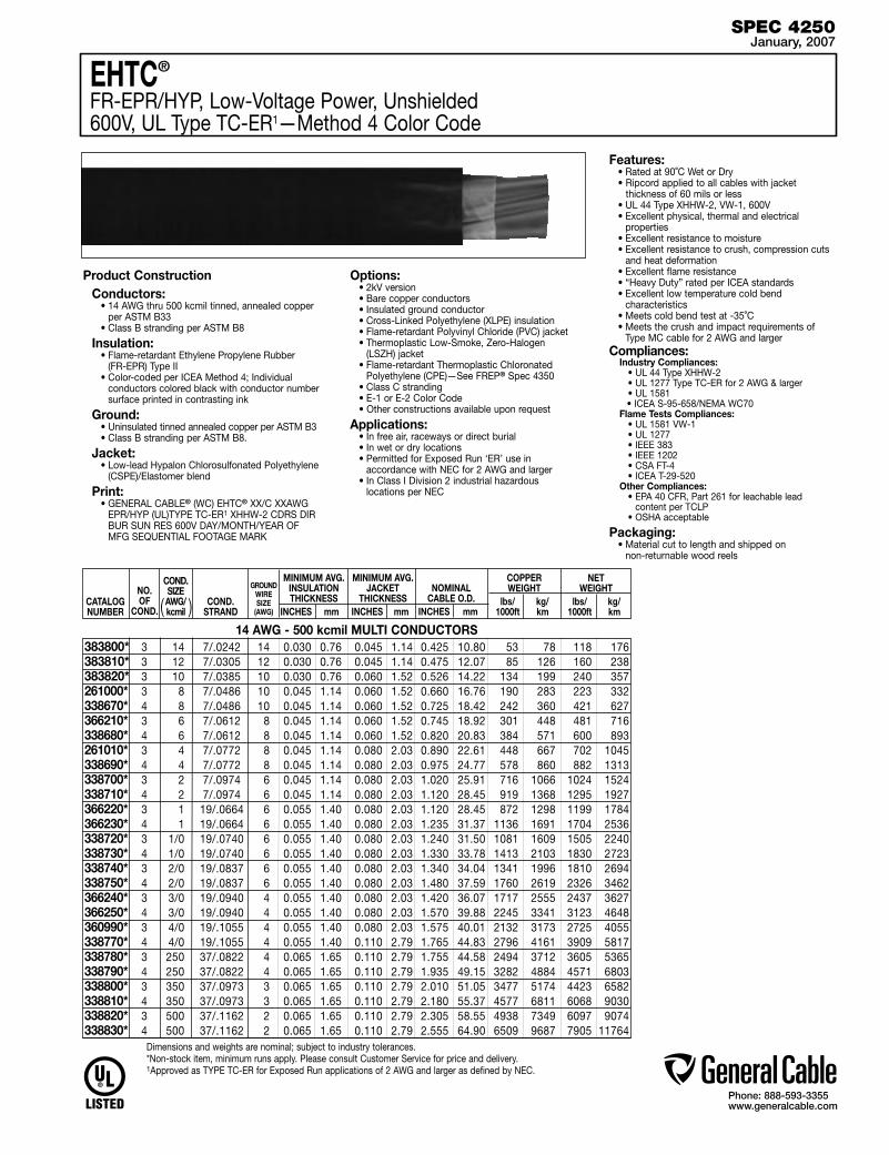
Phone: 888-593-3355www.generalcable.com
SPEC 4250January, 2007
EHTC®
FR-EPR/HYP, Low-Voltage Power, Unshielded600V, UL Type TC-ER1—Method 4 Color Code
Product ConstructionConductors:
• 14 AWG thru 500 kcmil tinned, annealed copper per ASTM B33
• Class B stranding per ASTM B8
Insulation:• Flame-retardant Ethylene Propylene Rubber
(FR-EPR) Type II • Color-coded per ICEA Method 4; Individual
conductors colored black with conductor number surface printed in contrasting ink
Ground:• Uninsulated tinned annealed copper per ASTM B3• Class B stranding per ASTM B8.
Jacket:• Low-lead Hypalon Chlorosulfonated Polyethylene
(CSPE)/Elastomer blend
Print:• GENERAL CABLE® (WC) EHTC® XX/C XXAWG
EPR/HYP (UL)TYPE TC-ER1 XHHW-2 CDRS DIR BUR SUN RES 600V DAY/MONTH/YEAR OF MFG SEQUENTIAL FOOTAGE MARK
Options:• 2kV version• Bare copper conductors• Insulated ground conductor• Cross-Linked Polyethylene (XLPE) insulation• Flame-retardant Polyvinyl Chloride (PVC) jacket• Thermoplastic Low-Smoke, Zero-Halogen
(LSZH) jacket• Flame-retardant Thermoplastic Chloronated
Polyethylene (CPE)—See FREP® Spec 4350• Class C stranding• E-1 or E-2 Color Code• Other constructions available upon request
Applications: • In free air, raceways or direct burial • In wet or dry locations• Permitted for Exposed Run ‘ER’ use in
accordance with NEC for 2 AWG and larger• In Class I Division 2 industrial hazardous
locations per NEC
Features:• Rated at 90˚C Wet or Dry• Ripcord applied to all cables with jacket
thickness of 60 mils or less• UL 44 Type XHHW-2, VW-1, 600V• Excellent physical, thermal and electrical
properties• Excellent resistance to moisture• Excellent resistance to crush, compression cuts
and heat deformation• Excellent flame resistance • “Heavy Duty” rated per ICEA standards• Excellent low temperature cold bend
characteristics • Meets cold bend test at -35˚C• Meets the crush and impact requirements of
Type MC cable for 2 AWG and largerCompliances:
Industry Compliances: • UL 44 Type XHHW-2 • UL 1277 Type TC-ER for 2 AWG & larger • UL 1581 • ICEA S-95-658/NEMA WC70Flame Tests Compliances: • UL 1581 VW-1 • UL 1277 • IEEE 383 • IEEE 1202 • CSA FT-4 • ICEA T-29-520Other Compliances: • EPA 40 CFR, Part 261 for leachable lead content per TCLP • OSHA acceptable
Packaging:• Material cut to length and shipped on
non-returnable wood reels
CATALOG NUMBER
NO.OF
COND.
MINIMUM AVG. INSULATION THICKNESS
INCHES mm
MINIMUM AVG. JACKET
THICKNESS INCHES mm
NOMINAL CABLE O.D.
INCHES mm
COND.STRAND
GROUNDWIRESIZE
(AWG)
COPPER WEIGHT
lbs/ kg/ 1000ft km
NET WEIGHT
lbs/ kg/ 1000ft km
COND.SIZE AWG/kcmil
3 14 7/.0242 14 0.030 0.76 0.045 1.14 0.425 10.80 53 78 118 176 3 12 7/.0305 12 0.030 0.76 0.045 1.14 0.475 12.07 85 126 160 238 3 10 7/.0385 10 0.030 0.76 0.060 1.52 0.526 14.22 134 199 240 357 3 8 7/.0486 10 0.045 1.14 0.060 1.52 0.660 16.76 190 283 223 332 4 8 7/.0486 10 0.045 1.14 0.060 1.52 0.725 18.42 242 360 421 627 3 6 7/.0612 8 0.045 1.14 0.060 1.52 0.745 18.92 301 448 481 716 4 6 7/.0612 8 0.045 1.14 0.060 1.52 0.820 20.83 384 571 600 893 3 4 7/.0772 8 0.045 1.14 0.080 2.03 0.890 22.61 448 667 702 1045 4 4 7/.0772 8 0.045 1.14 0.080 2.03 0.975 24.77 578 860 882 1313 3 2 7/.0974 6 0.045 1.14 0.080 2.03 1.020 25.91 716 1066 1024 1524 4 2 7/.0974 6 0.045 1.14 0.080 2.03 1.120 28.45 919 1368 1295 1927 3 1 19/.0664 6 0.055 1.40 0.080 2.03 1.120 28.45 872 1298 1199 1784 4 1 19/.0664 6 0.055 1.40 0.080 2.03 1.235 31.37 1136 1691 1704 2536 3 1/0 19/.0740 6 0.055 1.40 0.080 2.03 1.240 31.50 1081 1609 1505 2240 4 1/0 19/.0740 6 0.055 1.40 0.080 2.03 1.330 33.78 1413 2103 1830 2723 3 2/0 19/.0837 6 0.055 1.40 0.080 2.03 1.340 34.04 1341 1996 1810 2694 4 2/0 19/.0837 6 0.055 1.40 0.080 2.03 1.480 37.59 1760 2619 2326 3462 3 3/0 19/.0940 4 0.055 1.40 0.080 2.03 1.420 36.07 1717 2555 2437 3627 4 3/0 19/.0940 4 0.055 1.40 0.080 2.03 1.570 39.88 2245 3341 3123 4648 3 4/0 19/.1055 4 0.055 1.40 0.080 2.03 1.575 40.01 2132 3173 2725 4055 4 4/0 19/.1055 4 0.055 1.40 0.110 2.79 1.765 44.83 2796 4161 3909 5817 3 250 37/.0822 4 0.065 1.65 0.110 2.79 1.755 44.58 2494 3712 3605 5365 4 250 37/.0822 4 0.065 1.65 0.110 2.79 1.935 49.15 3282 4884 4571 6803 3 350 37/.0973 3 0.065 1.65 0.110 2.79 2.010 51.05 3477 5174 4423 6582 4 350 37/.0973 3 0.065 1.65 0.110 2.79 2.180 55.37 4577 6811 6068 9030 3 500 37/.1162 2 0.065 1.65 0.110 2.79 2.305 58.55 4938 7349 6097 9074 4 500 37/.1162 2 0.065 1.65 0.110 2.79 2.555 64.90 6509 9687 7905 11764
Dimensions and weights are nominal; subject to industry tolerances.*Non-stock item, minimum runs apply. Please consult Customer Service for price and delivery.1Approved as TYPE TC-ER for Exposed Run applications of 2 AWG and larger as defined by NEC.
14 AWG - 500 kcmil MULTI CONDUCTORS383800*383810*383820*261000* 338670* 366210* 338680* 261010* 338690* 338700*338710* 366220*366230*338720* 338730* 338740* 338750*366240*366250* 360990* 338770*338780* 338790* 338800* 338810* 338820* 338830*
( )
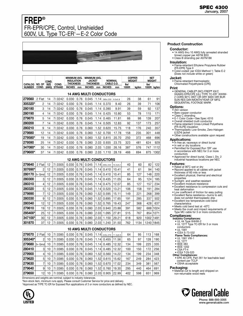
Phone: 888-593-3355www.generalcable.com
SPEC 4300January, 2007
2 Flat 12 7/.0305 0.030 0.76 0.045 1.14 40 60 82 122
2 12 7/.0305 0.030 0.76 0.045 1.14 0.410 10.41 41 61 94 140
3+ Grnd 12 7/.0305 0.030 0.76 0.045 1.14 0.410 10.41 85 127 148 220
3 12 7/.0305 0.030 0.76 0.045 1.14 0.435 11.05 64 95 124 185
4 12 7/.0305 0.030 0.76 0.045 1.14 0.475 12.07 85 127 157 234
5 12 7/.0305 0.030 0.76 0.045 1.14 0.520 13.21 106 158 191 284
7 12 7/.0305 0.030 0.76 0.060 1.52 0.595 15.11 149 221 268 399
9 12 7/.0305 0.030 0.76 0.060 1.52 0.695 17.65 191 285 337 502
12 12 7/.0305 0.030 0.76 0.060 1.52 0.765 19.43 247 368 428 637
19 12 7/.0305 0.030 0.76 0.080 2.03 0.940 23.88 391 582 688 1024
25 12 7/.0305 0.030 0.76 0.080 2.03 1.095 27.81 515 767 854 1271
30 12 7/.0305 0.030 0.76 0.080 2.03 1.150 29.21 618 920 1002 1491
37 12 7/.0305 0.030 0.76 0.080 2.03 1.240 31.50 762 1134 1240 1845
2 Flat 10 7/.0385 0.030 0.76 0.045 1.14 64 95 113 168
2 10 7/.0385 0.030 0.76 0.045 1.14 0.455 11.56 65 97 128 190
3+ Grnd 10 7/.0385 0.030 0.76 0.045 1.14 0.485 12.32 134 199 225 335
3 10 7/.0385 0.030 0.76 0.045 1.14 0.485 12.32 100 150 172 256
4 10 7/.0385 0.030 0.76 0.060 1.52 0.560 14.22 134 199 234 348
5 10 7/.0385 0.030 0.76 0.060 1.52 0.615 15.62 167 249 284 423
7 10 7/.0385 0.030 0.76 0.060 1.52 0.670 17.02 234 349 381 567
9 10 7/.0385 0.030 0.76 0.060 1.52 0.760 19.30 295 440 464 691
12 10 7/.0385 0.030 0.76 0.080 2.03 0.905 22.99 402 598 651 969
FREP®
FR-EPR/CPE, Control, Unshielded600V, UL Type TC-ER1—E-2 Color Code
10 AWG MULTI CONDUCTORS
2 Flat 14 7/.0242 0.030 0.76 0.045 1.14 26 38 61 91
2 14 7/.0242 0.030 0.76 0.045 1.14 0.370 9.40 26 39 71 106
3 14 7/.0242 0.030 0.76 0.045 1.14 0.390 9.91 39 59 92 137
4 14 7/.0242 0.030 0.76 0.045 1.14 0.425 10.80 53 78 115 171
5 14 7/.0242 0.030 0.76 0.045 1.14 0.465 11.81 66 98 139 207
7 14 7/.0242 0.030 0.76 0.045 1.14 0.505 12.83 92 137 173 257
9 14 7/.0242 0.030 0.76 0.060 1.52 0.620 15.75 118 176 240 357
12 14 7/.0242 0.030 0.76 0.060 1.52 0.700 17.78 158 235 301 448
19 14 7/.0242 0.030 0.76 0.060 1.52 0.815 20.70 250 372 468 696
25 14 7/.0242 0.030 0.76 0.080 2.03 0.935 23.75 323 481 624 929
30 14 7/.0242 0.030 0.76 0.080 2.03 1.030 26.16 387 576 747 1112
37 14 7/.0242 0.030 0.76 0.080 2.03 1.110 28.19 466 694 875 1302
279560 305320* 280180 280190 279870 280200 280210 279880 279580*279590 347080*279600*
Product ConstructionConductor:
• 14 AWG thru 10 AWG fully annealed stranded tinned copper per ASTM B33
• Class B stranding per ASTM B8
Insulation:• Flame-retardant Ethylene Propylene Rubber
(FR-EPR) Type II• Color-coded: per ICEA Method 1; Table E-2
(Does not include white or green)
Jacket:• Flame-retardant thermoplastic
Chlorinated Polyethylene (CPE)
Print• GENERAL CABLE® (WC) FREP® XX/C
XXAWG EPR/CPE (UL) TYPE TC-ER1 XHHW-2 CDRS 90°C WET OR DRY 600V DIR BUR SUN RES DAY/MONTH/YEAR OF MFG SEQUENTIAL FOOTAGE MARK
Options:• 2kV version• Bare copper conductor• Class C stranding• E-1 Color Code—See Spec 4310• Overall shielded multi conductor• Flame-retardant Cross-Linked Polyethene
(FR-XLPE) insulation• Thermoplastic Low-Smoke, Zero-Halogen
(LSZH) jacket• Other constructions available upon request
Applications:• In free air, raceways or direct burial• In wet or dry locations• Permitted for Exposed Run ‘ER’ use
in accordance with NEC for 3 or more conductors
• Approved for direct burial, Class I, Div. 2 industrial hazardous locations per NEC
Features:• Rated at 90˚C wet or dry• Ripcord applied to all cables with jacket
thickness of 60 mils or less• Excellent physical, thermal and electrical
properties• Sunlight- and weather-resistant• Excellent moisture resistance• Excellent resistance to compression cuts and
heat deformation• Low coefficient of friction for easy pulling• Excellent flame resistance—burns to ash;
does not exhibit thermoplastic drip• Excellent low temperature cold bend
characteristics• Meets cold bend test at -40˚C• Meets the crush and impact requirements of
Type MC cable for 3 or more conductorsCompliances:
Industry Compliances: • UL 44 Type XHHW-2 • UL 1277 Type TC-ER for 3 or more conductors • UL 1581 • ICEA S-73-532 Flame Tests Compliances: • UL 1581 VW-1 • UL 1277 • IEEE 383 • IEEE 1202 • CSA FT-4 • ICEA T-29-520Other Compliances: • EPA 40 CFR, Part 261 for leachable lead
content per TCLP • OSHA acceptable
Packaging:• Material cut to length and shipped on
non-returnable wood reels
12 AWG MULTI CONDUCTORS
14 AWG MULTI CONDUCTORS
279840 307690* 280170 280300 280310 280320 279890 280330 280340 279610295400*347100*301870
279570 305340* 279680 280410 279900 279620 279630 279640 279650
CATALOG NUMBER
NO. OF COND.
MINIMUM AVG. INSULATION THICKNESS
INCHES mm
MINIMUM AVG. JACKET
THICKNESS INCHES mm
NOMINAL CABLE O.D.
INCHES mm
COND.STRAND
COPPER WEIGHT
lbs/ 1000ft kg/km
NET WEIGHT
lbs/ 1000ft kg/km
COND.SIZE
(AWG)
Dimensions and weights are nominal; subject to industry tolerances.*Non-stock item, minimum runs apply. Please consult Customer Service for price and delivery.1Approved as TYPE TC-ER for Exposed Run applications of 3 or more conductors as defined by NEC.
.365x.230 9.3x5.8
.400x.245 10.2x6.2
.445x.270 11.3x6.9

Phone: 888-593-3355www.generalcable.com
SPEC 4310January, 2007
Product ConstructionConductor:
• 14 AWG thru 10 AWG fully annealed stranded tinned copper per ASTM B33
• Class B stranding per ASTM B8
Insulation:• Flame-retardant Ethylene Propylene Rubber
(FR-EPR) Type II• Color-coded per ICEA Method 1; Table E-1
(Does not include white or green)
Jacket:• Flame-retardant thermoplastic
Chlorinated Polyethylene (CPE)
Print• GENERAL CABLE® (WC) FREP® XX/C
XXAWG EPR/CPE (UL) TYPE TC-ER1 XHHW-2 CDRS 90°C WET OR DRY 600V DIR BUR SUN RES DAY/MONTH/YEAR OF MFG SEQUENTIAL FOOTAGE MARK
Options:• 2kV version• Bare copper conductor• Class C stranding• E-2 Color Code—See Spec 4300• Overall shielded multi conductor• Flame-retardant Cross-Linked Polyethene
(FR-XLPE) insulation• Thermoplastic Low-Smoke, Zero-Halogen
(LSZH) jacket• Other constructions available upon request
Applications:• In free air, raceways or direct burial• In wet or dry locations• Permitted for Exposed Run ‘ER’ use
in accordance with NEC for 3 or more conductors
• Approved for direct burial, Class I, Div. 2 industrial hazardous locations per NEC
Features:• Rated at 90˚C wet or dry• Ripcord applied to all cables with jacket
thickness of 60 mils or less• Excellent physical, thermal and electrical
properties• Sunlight- and weather-resistant• Excellent moisture resistance• Excellent resistance to compression cuts and
heat deformation• Low coefficient of friction for easy pulling• Excellent flame resistance—burns to ash;
does not exhibit thermoplastic drip• Excellent low temperature cold bend
characteristics• Meets cold bend test at -357 ptC• Meets the crush and impact requirements of
Type MC cable for 3 or more conductorsCompliances:
Industry Compliances: • UL 44 Type XHHW-2 • UL 1277 Type TC-ER for 3 or more conductors • UL 1581 • ICEA S-73-532 • ICEA S-95-658/NEMA WC70Flame Tests Compliances: • UL 1581 VW-1 • UL 1277 • IEEE 383 • IEEE 1202 • CSA FT-4 • ICEA T-29-520Other Compliances: • EPA 40 CFR, Part 261 for leachable lead
content per TCLP • OSHA acceptable
Packaging:• Material cut to length and shipped on
non-returnable wood reels
2 Flat 14 7/.0242 0.030 0.76 0.045 1.14 26 38 61 91
3 14 7/.0242 0.030 0.76 0.045 1.14 0.390 9.91 39 59 92 137
4 14 7/.0242 0.030 0.76 0.045 1.14 0.425 10.80 53 78 115 171
5 14 7/.0242 0.030 0.76 0.045 1.14 0.465 11.81 66 98 139 207
7 14 7/.0242 0.030 0.76 0.045 1.14 0.505 12.83 92 137 173 257
9 14 7/.0242 0.030 0.76 0.060 1.52 0.620 15.75 118 176 240 357
12 14 7/.0242 0.030 0.76 0.060 1.52 0.700 17.78 158 235 301 448
19 14 7/.0242 0.030 0.76 0.060 1.52 0.815 20.70 250 372 468 696
25 14 7/.0242 0.030 0.76 0.080 2.03 0.935 23.75 323 481 624 929
30 14 7/.0242 0.030 0.76 0.080 2.03 1.030 26.16 387 576 747 1112
37 14 7/.0242 0.030 0.76 0.080 2.03 1.110 28.19 466 694 875 1302
2 Flat 12 7/.0305 0.030 0.76 0.045 1.14 40 60 82 122
2 12 7/.0305 0.030 0.76 0.045 1.14 0.410 10.41 41 61 94 140
3 12 7/.0305 0.030 0.76 0.045 1.14 0.435 11.05 64 95 124 185
4 12 7/.0305 0.030 0.76 0.045 1.14 0.475 12.07 85 127 157 234
5 12 7/.0305 0.030 0.76 0.045 1.14 0.520 13.21 106 158 191 284
7 12 7/.0305 0.030 0.76 0.060 1.52 0.595 15.11 149 221 268 399
9 12 7/.0305 0.030 0.76 0.060 1.52 0.695 17.65 191 285 337 502
12 12 7/.0305 0.030 0.76 0.060 1.52 0.765 19.43 247 368 428 637
19 12 7/.0305 0.030 0.76 0.080 2.03 0.940 23.88 391 582 688 1024
25 12 7/.0305 0.030 0.76 0.080 2.03 1.095 27.81 515 767 854 1271
30 12 7/.0305 0.030 0.76 0.080 2.03 1.150 29.21 618 920 1002 1491
37 12 7/.0305 0.030 0.76 0.080 2.03 1.240 31.50 762 1134 1240 1845
2 Flat 10 7/.0385 0.030 0.76 0.045 1.14 64 95 113 168
2 10 7/.0385 0.030 0.76 0.045 1.14 0.455 11.56 65 97 128 190
3 10 7/.0385 0.030 0.76 0.045 1.14 0.485 12.32 100 150 172 256
4 10 7/.0385 0.030 0.76 0.060 1.52 0.560 14.22 134 199 234 348
5 10 7/.0385 0.030 0.76 0.060 1.52 0.615 15.62 167 249 284 423
7 10 7/.0385 0.030 0.76 0.060 1.52 0.670 17.02 234 349 381 567
9 10 7/.0385 0.030 0.76 0.060 1.52 0.760 19.30 295 440 464 691
12 10 7/.0385 0.030 0.76 0.080 2.03 0.905 22.99 402 598 651 969
10 AWG MULTI CONDUCTORS
280590 280230 280240 280250 280260 280270 280280 280290*385350*385360*385370*
12 AWG MULTI CONDUCTORS
14 AWG MULTI CONDUCTORS
279850 280350 280360 279910 280370 280380 280390* 280400 383930*383940*383950*330800*
280600* 280420* 279920 279930 330990* 280430* 382880* 383970*
CATALOG NUMBER
NO. OF COND.
MINIMUM AVG. INSULATION THICKNESS
INCHES mm
MINIMUM AVG. JACKET
THICKNESS INCHES mm
NOMINAL CABLE O.D.
INCHES mm
COND.STRAND
COPPER WEIGHT
lbs/ 1000ft kg/km
NET WEIGHT
lbs/ 1000ft kg/km
COND.SIZE
(AWG)
.365x.230 9.3x5.8
.400x.245 10.2x6.2
.445x.270 11.3x6.9
FREP®
FR-EPR/CPE, Control, Unshielded600V, UL Type TC-ER1—E-1 Color Code
Dimensions and weights are nominal; subject to industry tolerances.*Non-stock item, minimum runs apply. Please consult Customer Service for price and delivery.1Approved as TYPE TC-ER for Exposed Run applications of 3 or more conductors as defined by NEC.
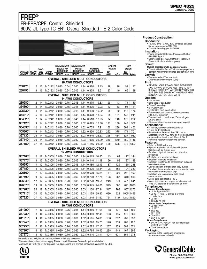
Phone: 888-593-3355www.generalcable.com
SPEC 4325January, 2007
FREP®
FR-EPR/CPE, Control, Shielded600V, UL Type TC-ER1, Overall Shielded—E-2 Color Code
Product ConstructionConductor:
• 16 AWG thru 10 AWG fully annealed stranded tinned copper per ASTM B33
• Class B stranding per ASTM B8Insulation:
• Flame-retardant Ethylene Propylene Rubber (FR-EPR) Type II
• Color-coded per ICEA Method 1; Table E-2 (Does not include white or green)
Shield:Overall shielded multi-conductor cable• Overall shield is Flexfoil® aluminum/polyester in
contact with stranded tinned copper drain wireJacket:
• Flame-retardant Thermoplastic Chlorinated Polyethylene (CPE)
Print• GENERAL CABLE® (WC) SHIELDED FREP®
XX/C XXAWG EPR/CPE (UL) TYPE TC-ER1 XHHW-2 CDRS 90˚C WET OR DRY 600V DIR BUR SUN RES DAY/MONTH/YEAR OF MFG SEQUENTIAL FOOTAGE MARK
Options:• 2kV version• Bare copper conductor• Class C stranding• E-1 Color Code• Unshielded multi conductors• Flame-retardant Cross-Linked Polyethene
(FR-XLPE) insulation• Thermoplastic Low-Smoke, Zero-Halogen
(LSZH) jacket• Other constructions available upon request
Applications:• In free air, raceway and direct burial• In wet or dry locations• Permitted for Exposed Run ‘ER’ use in
accordance with NEC for 3 or more conductors• Approved for direct burial, Class I, Div. 2
industrial hazardous locations per NEC Features:
• Rated at 90˚C wet or dry• Ripcord applied to all cables with jacket
thickness of 60 mils or less• Excellent physical, thermal and electrical
properties• Sunlight- and weather-resistant• Excellent moisture resistance• Excellent resistance to compression cuts and
heat deformation• Low coefficient of friction for easy pulling• Excellent flame resistance—burns to ash; does
not exhibit thermoplastic drip• Excellent low temperature cold bend
characteristics• Meets cold bend test at -40˚C• Meets the crush and impact requirements of
Type MC cable for 3 conductors or moreCompliances:
Industry Compliances: • UL 44 Type XHHW-2 • UL 1277 Type TC-ER for 3 or more conductors • UL 1581 • ICEA S-73-532 Flame Tests Compliances: • UL 1581 VW-1 • UL 1277 • IEEE 383 • IEEE 1202 • CSA FT-4 • ICEA T-29-520Other Compliances: • EPA 40 CFR, Part 261 for leachable lead
content per TCLP • OSHA acceptable
Packaging:• Material cut to length and shipped on
non-returnable wood reels
CATALOG NUMBER
NO. OF COND.
MINIMUM AVG. INSULATION THICKNESS
INCHES mm
MINIMUM AVG. JACKET
THICKNESS INCHES mm
NOMINAL CABLE O.D.
INCHES mm
COND.STRAND
COPPER WEIGHT
lbs/ 1000ft kg/km
NET WEIGHT
lbs/ 1000ft kg/km
COND.SIZE
(AWG)
2 16 7/.0192 0.025 0.64 0.045 1.14 0.320 8.13 19 28 52 77
3 16 7/.0192 0.025 0.64 0.045 1.14 0.335 8.51 27 40 66 98
280470280490
OVERALL SHIELDED MULTI CONDUCTORS16 AWG CONDUCTORS
2 14 7/.0242 0.030 0.76 0.045 1.14 0.375 9.53 29 43 74 110
3 14 7/.0242 0.030 0.76 0.045 1.14 0.395 10.03 42 63 95 141
4 14 7/.0242 0.030 0.76 0.045 1.14 0.430 10.92 55 82 118 176
5 14 7/.0242 0.030 0.76 0.045 1.14 0.470 11.94 68 101 142 211
7 14 7/.0242 0.030 0.76 0.045 1.14 0.510 12.95 94 140 176 262
9 14 7/.0242 0.030 0.76 0.060 1.52 0.625 15.88 121 180 243 362
12 14 7/.0242 0.030 0.76 0.060 1.52 0.705 17.91 160 238 304 452
19 14 7/.0242 0.030 0.76 0.060 1.52 0.820 20.83 252 375 471 701
25 14 7/.0242 0.030 0.76 0.080 2.03 0.940 25.53 325 484 627 933
30 14 7/.0242 0.030 0.76 0.080 2.03 1.035 26.29 389 579 750 1116
37 14 7/.0242 0.030 0.76 0.080 2.03 1.115 28.32 468 696 878 1307
280980*354800*305330*354810*354820*367120*354830*305360*367130*367140*367150*
OVERALL SHIELDED MULTI CONDUCTORS14 AWG CONDUCTORS
OVERALL SHIELDED MULTI CONDUCTORS12 AWG CONDUCTORS
2 12 7/.0305 0.030 0.76 0.045 1.14 0.415 10.45 43 64 97 144
3 12 7/.0305 0.030 0.76 0.045 1.14 0.440 11.18 66 98 127 189
4 12 7/.0305 0.030 0.76 0.045 1.14 0.480 12.19 87 129 160 238
5 12 7/.0305 0.030 0.76 0.045 1.14 0.525 13.34 108 162 194 289
7 12 7/.0305 0.030 0.76 0.060 1.52 0.600 15.24 151 225 271 403
9 12 7/.0305 0.030 0.76 0.060 1.52 0.700 17.78 193 287 340 506
12 12 7/.0305 0.030 0.76 0.060 1.52 0.770 19.56 249 371 431 641
19 12 7/.0305 0.030 0.76 0.080 2.03 0.945 24.00 393 585 691 1028
25 12 7/.0305 0.030 0.76 0.080 2.03 1.100 27.94 517 769 857 1275
30 12 7/.0305 0.030 0.76 0.080 2.03 1.155 29.80 620 923 1005 1496
37 12 7/.0305 0.030 0.76 0.080 2.03 1.245 31.62 764 1137 1243 1850
367160*367170*326650*367180*326660*367190*326640*326670*367200*367210*367220*
OVERALL SHIELDED MULTI CONDUCTORS10 AWG CONDUCTORS
2 10 7/.0385 0.030 0.76 0.045 1.14 0.460 11.68 68 101 131 195
3 10 7/.0385 0.030 0.76 0.045 1.14 0.490 12.45 103 155 175 260
4 10 7/.0385 0.030 0.76 0.060 1.52 0.565 14.35 136 202 237 353
5 10 7/.0385 0.030 0.76 0.060 1.52 0.620 15.75 170 253 287 427
7 10 7/.0385 0.030 0.76 0.060 1.52 0.675 17.15 237 353 384 571
9 10 7/.0385 0.030 0.76 0.060 1.52 0.765 19.43 298 443 467 695
12 10 7/.0385 0.030 0.76 0.080 2.03 0.910 23.11 404 601 654 973
311900*367230*311910*367240*367250*367260*367270*
Dimensions and weights are nominal; subject to industry tolerances.*Non-stock item, minimum runs apply. Please consult Customer Service for price and delivery.1Approved as TYPE TC-ER for Exposed Run applications of 3 or more conductors as defined by NEC.
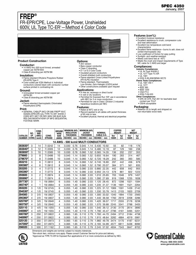
Phone: 888-593-3355www.generalcable.com
SPEC 4350January, 2007
Dimensions and weights are nominal; subject to industry tolerances.*Non-stock item, minimum runs apply. Please consult Customer Service for price and delivery.1Approved as TYPE TC-ER for Exposed Run applications of 3 or more conductors as defined by NEC.
FREP®
FR-EPR/CPE, Low-Voltage Power, Unshielded600V, UL Type TC-ER1—Method 4 Color Code
Product ConstructionConductor:
• 14 AWG thru 500 kcmil tinned, annealed copper per ASTM B33
• Class B stranding per ASTM B8
Insulation:• Flame-retardant Ethylene Propylene Rubber
(FR-EPR) Type II• Color-coded per ICEA Method 4; Individual
conductors colored black with conductor number surface printed in contrasting ink
Ground:• Uninsulated tinned annealed copper per
ASTM B3• Class B stranding per ASTM B8
Jacket:• Flame-retardant thermoplastic Chlorinated
Polyethylene (CPE)
Print:• GENERAL CABLE® (WC) OR (MI) FREP® XX/C
XXAWG EPR/CPE (UL) TYPE TC-ER1 XHHW-2 CDRS 90˚C WET OR DRY 600V DIR BUR SUN RES DAY/MONTH/YEAR OF MFG SEQUENTIAL FOOTAGE MARK
Options:• 2kV version• Bare copper conductor• Class C stranding• E-1 or E-2 Color Code• Insulated ground conductors• Overall shielded multi conductors• Flame-retardant Cross-Linked Polyethylene
(FR-XLPE) insulation• Flame-retardant, Thermoplastic
Low-Smoke, Zero-Halogen (LSZH) jacket• Other constructions available upon request
Applications:• In free air, raceways or direct burial • In wet or dry locations• Permitted for Exposed Run ‘ER’ use in accordance
with NEC for 3 or more conductors• Permitted for use in Class I Division 2 industrial
hazardous locations per NEC
Features:• Rated at 90˚C wet or dry• Ripcord applied to all cables with jacket thickness
of 60 mils or less• Excellent physical, thermal and electrical properties
Features (con’t.):• Excellent moisture resistance• Excellent resistance to crush, compression cuts
and heat deformation• Excellent low temperature cold bend
characteristics• Excellent flame resistance—burns to ash; does not
exhibit thermoplastic drip• Low coefficient of friction for easy pulling• Sunlight- and weather-resistant• Meets cold bend test at -40˚C• Meets the crush and impact requirements of Type
MC cable for 2 AWG and larger
Compliances:Industry Compliances: • UL 44 Type XHHW-2 • UL 1277 Type TC-ER • UL 1581 • ICEA S-95-658/NEMA WC70Flame Tests Compliances: • UL 1581 VW-1 • UL 1277 • IEEE 383 • IEEE 1202 • CSA FT-4 • ICEA T-29-520Other Compliances: • EPA 40 CFR, Part 261 for leachable lead content per TCLP • OSHA acceptable
Packaging:• Material cut to length and shipped on
non-returnable wood reels
CATALOG NUMBER
NO.OF
COND.
MINIMUM AVG. INSULATION THICKNESS
INCHES mm
MINIMUM AVG. JACKET
THICKNESS INCHES mm
NOMINAL CABLE O.D.
INCHES mm
COND.STRAND
GROUNDWIRESIZE
(AWG)
COPPER WEIGHT
lbs/ kg/ 1000ft km
NET WEIGHT
lbs/ kg/ 1000ft km
COND.SIZE AWG/kcmil
3 14 7/.0242 14 0.030 0.76 0.045 1.14 0.430 10.92 55 82 118 176 3 12 7/.0305 12 0.030 0.76 0.045 1.14 0.480 12.19 87 129 160 238 3 10 7/.0385 10 0.030 0.76 0.060 1.52 0.565 14.35 136 202 237 353 3 8 7/.0486 10 0.045 1.14 0.060 1.52 0.655 16.64 190 283 314 467 4 8 7/.0486 10 0.045 1.14 0.060 1.52 0.720 18.29 242 360 393 585 3 6 7/.0612 8 0.045 1.14 0.060 1.52 0.740 18.80 297 442 456 679 4 6 7/.0612 8 0.045 1.14 0.060 1.52 0.790 20.07 384 571 561 835 3 4 7/.0772 8 0.045 1.14 0.080 2.03 0.880 22.35 442 658 642 955 4 4 7/.0772 8 0.045 1.14 0.080 2.03 0.950 24.13 578 861 822 1223 3 2 7/.0974 6 0.045 1.14 0.080 2.03 1.010 25.65 703 1046 979 1457 4 2 7/.0974 6 0.045 1.14 0.080 2.03 1.090 27.69 919 1368 1235 1838 3 1 19/.0664 6 0.055 1.40 0.080 2.03 1.120 28.45 872 1298 1021 1594 4 1 19/.0664 6 0.055 1.40 0.080 2.03 1.235 31.37 1136 1691 1521 2264 3 1/0 19/.0745 6 0.055 1.40 0.080 2.03 1.225 31.12 1069 1591 1439 2142 4 1/0 19/.0745 6 0.055 1.40 0.080 2.03 1.330 33.78 1413 2103 1820 2709 3 2/0 19/.0837 6 0.055 1.40 0.080 2.03 1.300 33.02 1340 1994 1720 2560 4 2/0 19/.0837 6 0.055 1.40 0.080 2.03 1.440 36.58 1760 2619 2208 3286 3 3/0 19/.0940 4 0.055 1.40 0.080 2.03 1.420 36.07 1717 2555 2176 3238 4 3/0 19/.0940 4 0.055 1.40 0.080 2.03 1.570 39.88 2245 3341 2788 3405 3 4/0 19/.1055 4 0.055 1.40 0.080 2.03 1.540 39.12 2130 3170 2614 3890 4 4/0 19/.1055 4 0.055 1.40 0.110 2.79 1.790 45.47 2796 4161 3495 5201 3 250 37/.0822 4 0.065 1.65 0.110 2.79 1.760 44.70 2494 3712 3184 4738 4 250 37/.0822 4 0.065 1.65 0.110 2.79 1.915 48.64 3282 4884 4019 5981 3 350 37/.0973 3 0.065 1.65 0.110 2.79 1.960 49.78 3474 5170 4187 6231 4 350 37/.0973 3 0.065 1.65 0.110 2.79 2.165 54.99 4577 6811 5436 8090 3 500 37/.1162 2 0.065 1.65 0.110 2.79 2.245 57.02 4934 7343 5847 8702
383830*383840*383850*279660 279670* 283210 300380* 283200 295390* 293600285890* 297730*365740*283220 294530* 284560 295360*325700*365750* 325110 346980*300780* 346990* 325120 347000* 298020
14 AWG - 500 kcmil MULTI CONDUCTORS
( )

Phone: 888-593-3355www.generalcable.com
Product ConstructionConductor:
• 14 AWG thru 10 AWG tinned, annealed copper per ASTM B3
• Class B stranding per ASTM B8
Insulation:• Flame-retardant Cross-Linked Polyethylene
(XLPE) Color-coded per CSA Standard C22.2 No. 38 as follows:
Number of color coding of circuit conductorsNo. of Cond. Color Code 2 blk, wht 3 blk, red, blu 4 blk, red, blu, wht ≥5 all blackAll conductors for all constructions are alpha-numeric printed
Jacket:• Flame-retardant and sunlight-resistant Arctic-
grade Polyvinyl Chloride (PVC)
Print:• GENERAL CABLE® (WC) (UL) TYPE TC-ER1
ARCTIC-FLEX® XX/C XXAWG FR-XLP/PVC XHHW-2 CDRS 90C WET OR DRY SUN RES DIR BUR 600V - (CSA) TYPE RW90 XLPE -40C TC FT-4 600V PLUS DAY/MONTH/YEAR OF MFG SEQUENTIAL FOOTAGE MARK
Options:• Bare copper, class C stranding• Uninsulated ground (bonding) conductor• Optional color code as specified per CSA
standard C22.2 No. 38 for two to four conductor cable
• Non-UL 1000 volt CSA Type RW90 XLPE, CSA Type TC
• Other constructions available upon request
Applications:• Industrial lighting, control and signaling
circuits • Approved for direct burial, Class I, Div. 2
industrial hazardous locations per NEC for UL Type TC cables. In Canada, protection may be required by inspection authority per Canadian electrical code
• Permitted for Exposed Run ‘ER’ use in accordance with NEC for 3 or more conductors
• Approved for cable in tray, industrial hazardous locations, Class I, Zone 2, and Class II, Division 2 per CEC rules 18-156 and 18-252 when used with certified HL glands
Features:• Rated 90˚C wet or dry• Ripcord applied to all cables with jacket
thickness of 60 mils or less• Meets CSA cold impact test at -40˚C• Meets ICEA and CSA cold bend test at -65˚C• Meets the crush and impact requirements of
Type MC cableCompliances:
Industry Compliances: • ICEA S-73-532 • ICEA S-95-658/NEMA WC70 • UL 44 Type XHHW-2 • UL 1277 Type TC-ER for 3 or more conductors • UL 1581 • CSA C22.2 No. 38 XLPE RW90 • CSA C22.2 No. 230 Type TCFlame Tests Compliances: • UL 1581 VW-1 • UL 1277 • IEEE 383 • CSA FT-4Other Compliances: • EPA 40 CFR, Part 261 for leachable lead
content per TCLP • OSHA acceptable
Packaging:• Material cut to lengths and shipped on non-
returnable wood reels
SPEC 4400January, 2007
ARCTIC-FLEX®
XLPE/ARCTIC-PVC, Control, Unshielded600V, UL Type TC-ER1, CSA Type RW90 XLPE, CSA TYPE TC
12 AWG MULTI CONDUCTORS
14 AWG MULTI CONDUCTORS
2 12 7/.0305 0.030 0.76 0.045 1.14 0.410 10.41 41 61 96 143
3 12 7/.0305 0.030 0.76 0.045 1.14 0.435 11.05 65 96 125 186
4 12 7/.0305 0.030 0.76 0.045 1.14 0.475 12.07 86 128 157 234
5 12 7/.0305 0.030 0.76 0.045 1.14 0.520 13.21 108 160 191 284
7 12 7/.0305 0.030 0.76 0.060 1.52 0.595 15.11 150 224 260 387
9 12 7/.0305 0.030 0.76 0.060 1.52 0.695 17.65 193 288 340 506
12 12 7/.0305 0.030 0.76 0.060 1.52 0.780 19.81 258 385 429 638
19 12 7/.0305 0.030 0.76 0.080 2.03 0.930 23.62 403 600 681 1013
25 12 7/.0305 0.030 0.76 0.080 2.03 1.095 27.81 515 767 885 1317
30 12 7/.0305 0.030 0.76 0.080 2.03 1.150 29.21 618 920 1005 1496
37 12 7/.0305 0.030 0.76 0.080 2.03 1.240 31.50 741 1103 1185 1764
10 AWG MULTI CONDUCTORS 2 10 7/.0385 0.030 0.76 0.045 1.14 0.455 11.56 67 100 130 193
3 10 7/.0385 0.030 0.76 0.045 1.14 0.485 12.32 101 150 168 250
4 10 7/.0385 0.030 0.76 0.060 1.52 0.515 13.08 135 200 229 341
5 10 7/.0385 0.030 0.76 0.060 1.52 0.615 15.62 167 249 281 418
7 10 7/.0385 0.030 0.76 0.060 1.52 0.670 17.02 234 349 377 561
9 10 7/.0385 0.030 0.76 0.060 1.52 0.785 19.94 295 440 479 713
12 10 7/.0385 0.030 0.76 0.080 2.03 0.895 22.73 402 598 644 958
CATALOG NUMBER
NO. OF COND.
MINIMUM AVG. INSULATION THICKNESS
INCHES mm
MINIMUM AVG. JACKET
THICKNESS INCHES mm
NOMINAL CABLE O.D.
INCHES mm
COND.STRAND
COPPER WEIGHT
lbs/ 1000ft kg/km
NET WEIGHT
lbs/ 1000ft kg/km
COND.SIZE
(AWG)
2 14 7/.0242 0.030 0.76 0.045 1.14 0.405 10.29 25 37 71 106
3 14 7/.0242 0.030 0.76 0.045 1.14 0.390 9.91 40 59 90 134
4 14 7/.0242 0.030 0.76 0.045 1.14 0.425 10.80 53 79 113 168
5 14 7/.0242 0.030 0.76 0.045 1.14 0.465 11.81 66 99 140 208
7 14 7/.0242 0.030 0.76 0.045 1.14 0.590 14.99 93 138 176 262
9 14 7/.0242 0.030 0.76 0.060 1.52 0.620 15.75 119 177 245 365
12 14 7/.0242 0.030 0.76 0.060 1.52 0.680 17.27 159 237 302 449
19 14 7/.0242 0.030 0.76 0.060 1.52 0.800 20.32 252 375 460 685
25 14 7/.0242 0.030 0.76 0.060 1.52 0.985 25.02 323 481 641 954
30 14 7/.0242 0.030 0.76 0.080 2.03 1.050 26.67 387 576 740 1101
37 14 7/.0242 0.030 0.76 0.080 2.03 1.130 28.70 490 729 888 1322
Dimensions and weights are nominal; subject to industry tolerances.*Non-stock item, minimum runs apply. Please consult Customer Service for price and delivery.1Approved as TYPE TC-ER for Exposed Run applications of 3 or more conductors as defined by NEC.
347340*347350*347360*347370*347380*347390*347400*347410*347420*347430*347440*
347450*347460*347470*347480*347490*347500*347510*347520*347530*347540*347550*
347560*347570*347580*347590*347600*347610*347620*

Phone: 888-593-3355www.generalcable.com
SPEC 4450January, 2007
ARCTIC-FLEX®
XLPE/ARCTIC-PVC, Low-Voltage Power, Unshielded600V, UL Type TC-ER1, CSA Type RW90 XLPE, CSA TYPE TC
Product Construction
Conductor:• 8 AWG thru 500 kcmil bare, annealed copper per
ASTM B3• Class B stranding per ASTM B8
Insulation:• Flame-retardant Cross-Linked Polyethylene
(XLPE) Color-coded per CSA Standard C22.2 No. 38 as follows:
Number of color coding of circuit conductorsNo. of Cond. Color Code
2 blk, wht 3 blk, red, blu 4 blk, red, blu, wht ≥5 all black
All conductors for all constructions are alphanumeric printed
Ground (Bonding) Conductor:• Uninsulated bare annealed copper
per ASTM B3• Class B stranding per ASTM B8
Jacket:• Flame-retardant and sunlight-resistant
Arctic-grade Polyvinyl Chloride (PVC)
Print:• GENERAL CABLE® (WC) (UL) TYPE TC-ER1
ARCTIC-FLEX® XX/C XXAWG FR-XLP/PVC XHHW-2 CDRS 90C WET OR DRY SUN RES DIR BUR 600V (CSA) TYPE RW90 XLPE -40C TC FT-4 600V PLUS DAY/MONTH/YEAR OF MFG SEQUENTIAL FOOTAGE MARK
Options:• Tinned copper• Class C stranding• Overall shielded multi conductors• Optional Color Code as specified per CSA
standard C22.2 No. 38 for two to four conductor cable
• Non-UL 1000 volt CSA Type RW90 XLPE, CSA Type TC
• Other constructions are available upon request
Applications:• Industrial power and control circuits • Permitted for Exposed Run ‘ER’ use in
accordance with NEC for 3 or more conductors• Approved for direct burial, Class I, Div. 2
industrial hazardous locations per NEC for UL Type TC cables. In Canada protection may be required by inspection authority per Canadian electrical code
Applications (con’t):• Approved for cable in tray, industrial hazardous
locations, Class I, Zone 2, and Class II, Division 2 per CEC rules 18-156 and 18-252 when used with certified HL cable glands
Features:• Rated 90˚C wet or dry• Ripcord applied to all cables with jacket
thickness of 60 mils or less• Meets CSA cold impact test at -40˚C• Meets ICEA and CSA cold bend test at -65˚C• Meets the crush and impact requirements of
Type MC cable
Compliances:Industry Compliances: • UL 44 Type XHHW-2 • UL 1277 Type TC-ER for 3 or more conductors • UL 1581
• ICEA S-95-658/NEMA WC70 • CSA C22.2 No. 38 RW90 XLPE • CSA C22.2 No. 230 Type TCFlame Tests Compliances: • UL 1581 VW-1 • UL 1277 • IEEE 383 • IEEE 1202 • CSA FT-4Other Compliances: • EPA 40 CFR, Part 261 for leachable lead
content per TCLP • OSHA acceptable
Packaging:• Material cut to lengths and shipped on
non-returnable wood reels
CATALOG NUMBER
NO.OF
COND
COND. SIZE AWG/kcmil
MINIMUM AVG. INSULATION THICKNESS
INCHES mm
MINIMUM AVG. JACKET
THICKNESS INCHES mm
NOMINAL CABLE
O.D.INCHES mm
COPPER WEIGHT
lbs/ kg/ 1000ft km
NET WEIGHT
lbs/ kg/ 1000ft km
COND.STRAND
GROUNDWIRESIZE
(AWG)
3 8 7/.0486 10 0.045 1.14 0.060 1.52 0.640 16.26 190 283 314 467 4 8 7/.0486 10 0.045 1.14 0.060 1.52 0.705 17.91 242 360 385 573 3 6 7/.0612 8 0.045 1.14 0.060 1.52 0.720 18.29 301 448 445 662 4 6 7/.0612 8 0.045 1.14 0.060 1.52 0.790 20.07 384 571 558 830 3 4 7/.0772 8 0.045 1.14 0.080 2.03 0.875 22.23 448 667 653 972 4 4 7/.0772 8 0.045 1.14 0.080 2.03 0.950 24.13 578 862 820 1220 3 2 7/.0974 6 0.045 1.14 0.080 2.03 1.000 25.40 716 1066 964 1435 4 2 7/.0974 6 0.045 1.14 0.080 2.03 1.095 27.81 919 1368 1214 1807 3 1 19/.0664 6 0.055 1.40 0.080 2.03 1.120 28.45 872 1298 1199 1784 4 1 19/.0664 6 0.055 1.40 0.080 2.03 1.235 31.37 1136 1691 1704 2536 3 1/0 19/.0745 6 0.055 1.40 0.080 2.03 1.215 30.86 1081 1609 1414 2104 4 1/0 19/.0745 6 0.055 1.40 0.080 2.03 1.340 34.04 1413 2103 1825 2716 3 2/0 19/.0837 6 0.055 1.40 0.080 2.03 1.310 33.27 1341 1996 1706 2539 4 2/0 19/.0837 6 0.055 1.40 0.080 2.03 1.450 36.83 1760 2619 2223 3308 3 3/0 19/.0940 4 0.055 1.40 0.080 2.03 1.420 36.07 1717 2555 2437 3627 4 3/0 19/.0940 4 0.055 1.40 0.080 2.03 1.570 39.88 2245 3341 3123 4648 3 4/0 19/.1055 4 0.055 1.40 0.080 2.03 1.540 39.12 2132 3173 2600 3869 4 4/0 19/.1055 4 0.055 1.40 0.110 2.79 1.765 44.83 2796 4161 3444 5125 3 250 37/.0822 4 0.065 1.65 0.110 2.79 1.750 44.45 2494 3712 3142 4676 4 250 37/.0822 4 0.065 1.65 0.110 2.79 1.930 49.02 3282 4884 4048 6024 3 350 37/.0973 3 0.065 1.65 0.110 2.79 1.970 50.04 3474 5170 4230 6295 4 350 37/.0973 3 0.065 1.65 0.110 2.79 2.180 55.37 4577 6811 5470 8140 3 500 37/.1162 2 0.065 1.65 0.110 2.79 2.250 57.15 4938 7349 5829 8675
8 AWG - 500 kcmil MULTI CONDUCTORS347150*347160*347170*347180*347190*347200*347210*347220*371280*371290*347230*347240*347250*347260*371300*371310*347270*347280*347290*347300*347310*347320*347330*
Dimensions and weights are nominal; subject to industry tolerances.*Non-stock item, minimum runs apply. Please consult Customer Service for price and delivery.1Approved as TYPE TC-ER for Exposed Run applications of 3 or more conductors as defined by NEC.
( )
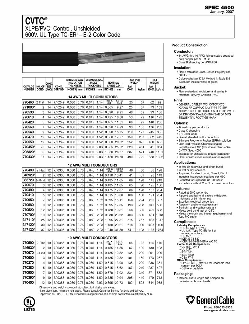
Phone: 888-593-3355www.generalcable.com
Product Construction
Conductor:• 14 AWG thru 10 AWG fully annealed stranded
bare copper per ASTM B3• Class B stranding per ASTM B8
Insulation:• Flame-retardant Cross-Linked Polyethylene
(XLPE)• Color-coded per ICEA Method 1; Table E-2
(Does not include white or green)
Jacket:• Flame-retardant, moisture- and sunlight-
resistant Polyvinyl Chloride (PVC)
Print• GENERAL CABLE® (WC) CVTC® XX/C
XXAWG FR-XLP/PVC (UL) TYPE TC-ER1 XHHW-2 CDRS DIR BUR SUN RES 90˚C WET OR DRY 600V DAY/MONTH/YEAR OF MFG SEQUENTIAL FOOTAGE MARK
Options:• Tinned copper conductor• Class C stranding• E-1 Color Code• Overall shielded multi conductors• Ethylene Propylene Rubber (EPR) insulation• Low-lead Hypalon Chlorosulfonated
Polyethylene (CSPE)/Elastomer blend—See CHTC® Spec 4050
• Insulated or uninsulated ground conductor• Other constructions available upon request
Applications:• In free air, raceways and direct burial• In wet or dry locations• Approved for direct burial, Class I, Div. 2
industrial hazardous locations per NEC • Permitted for Exposed Run ‘ER’ use in
accordance with NEC for 3 or more conductors
Features:• Rated at 90˚C wet or dry• Ripcord applied to all cables with jacket
thickness of 60 mils or less• Excellent electrical properties• Abrasion- and chemical-resistant• Sunlight- and weather-resistant• Meets cold bend test at -25˚C• Meets the crush and impact requirements of
Type MC cable
Compliances:Industry Compliances: • UL 44 Type XHHW-2 • UL 1277 Type TC-ER for 3 or more conductors • UL 1581
• ICEA S-73-532 • ICEA S-95-658/NEMA WC 70Flame Tests Compliances: • UL 1581 VW-1 • UL 1277 • IEEE 383 • IEEE 1202 • CSA FT-4Other Compliances: • EPA 40 CFR, Part 261 for leachable lead
content per TCLP • OSHA acceptable
Packaging:• Material cut to length and shipped on
non-returnable wood reels
SPEC 4500January, 2007
2 Flat 12 7/.0305 0.030 0.76 0.045 1.14 40 60 86 128
2 12 7/.0305 0.030 0.76 0.045 1.14 0.410 10.41 41 61 96 143
3+ Grnd 12 7/.0305 0.030 0.76 0.045 1.14 0.435 11.05 86 128 143 213
3 12 7/.0305 0.030 0.76 0.045 1.14 0.435 11.05 65 96 125 186
4 12 7/.0305 0.030 0.76 0.045 1.14 0.475 12.07 86 128 157 234
5 12 7/.0305 0.030 0.76 0.045 1.14 0.515 13.08 108 160 191 284
7 12 7/.0305 0.030 0.76 0.060 1.52 0.595 15.11 150 224 260 387
9 12 7/.0305 0.030 0.76 0.060 1.52 0.695 17.65 193 288 340 506
12 12 7/.0305 0.030 0.76 0.060 1.52 0.780 19.81 258 385 429 638
19 12 7/.0305 0.030 0.76 0.080 2.03 0.930 23.62 403 600 681 1013
25 12 7/.0305 0.030 0.76 0.080 2.03 1.095 27.81 515 767 885 1317
30 12 7/.0305 0.030 0.76 0.080 2.03 1.150 29.21 618 920 1005 1496
37 12 7/.0305 0.030 0.76 0.080 2.03 1.240 31.50 741 1103 1185 1764
2 Flat 10 7/.0385 0.030 0.76 0.045 1.14 66 98 114 170
2 10 7/.0385 0.030 0.76 0.045 1.14 0.455 11.56 67 100 130 193
3+ Grnd 10 7/.0385 0.030 0.76 0.045 1.14 0.485 12.32 135 200 201 299
3 10 7/.0385 0.030 0.76 0.045 1.14 0.485 12.32 101 150 173 257
4 10 7/.0385 0.030 0.76 0.060 1.52 0.515 13.08 135 200 236 351
5 10 7/.0385 0.030 0.76 0.060 1.52 0.615 15.62 167 249 287 427
7 10 7/.0385 0.030 0.76 0.060 1.52 0.670 17.02 234 349 371 552
9 10 7/.0385 0.030 0.76 0.060 1.52 0.785 19.94 295 440 479 713
12 10 7/.0385 0.030 0.76 0.080 2.03 0.895 22.73 402 598 644 958
CVTC®
XLPE/PVC, Control, Unshielded600V, UL Type TC-ER1—E-2 Color Code
CATALOG NUMBER
NO. OF COND.
MINIMUM AVG. INSULATION THICKNESS
INCHES mm
MINIMUM AVG. JACKET
THICKNESS INCHES mm
NOMINAL CABLE O.D.
INCHES mm
COND.STRAND
COPPER WEIGHT
lbs/ 1000ft kg/km
NET WEIGHT
lbs/ 1000ft kg/km
COND.SIZE
(AWG)
14 AWG MULTI CONDUCTORS 2 Flat 14 7/.0242 0.030 0.76 0.045 1.14 25 37 62 92
2 14 7/.0242 0.030 0.76 0.045 1.14 0.365 9.27 25 37 73 109
3 14 7/.0242 0.030 0.76 0.045 1.14 0.390 9.91 40 59 93 138
4 14 7/.0242 0.030 0.76 0.045 1.14 0.425 10.80 53 79 116 173
5 14 7/.0242 0.030 0.76 0.045 1.14 0.465 11.81 66 99 140 208
7 14 7/.0242 0.030 0.76 0.045 1.14 0.590 14.99 93 138 176 262
9 14 7/.0242 0.030 0.76 0.060 1.52 0.620 15.75 119 177 245 365
12 14 7/.0242 0.030 0.76 0.060 1.52 0.680 17.27 159 237 302 449
19 14 7/.0242 0.030 0.76 0.060 1.52 0.800 20.32 252 375 460 685
25 14 7/.0242 0.030 0.76 0.080 2.03 0.985 25.02 323 481 641 954
30 14 7/.0242 0.030 0.76 0.080 2.03 1.050 26.67 387 571 740 1101
37 14 7/.0242 0.030 0.76 0.080 2.03 1.130 28.70 490 729 888 1322
.235 X .370
5.97 X 9.40
12 AWG MULTI CONDUCTORS770480346920* 365720 770570 770490 770410 770950 770580 770520770700*347110*347120*347130*
.245 X .400
6.22 X 10.16
10 AWG MULTI CONDUCTORS770590346930*770670 770600 770370770380770900770390*770400
Dimensions and weights are nominal; subject to industry tolerances.*Non-stock item, minimum runs apply. Please consult Customer Service for price and delivery.1Approved as TYPE TC-ER for Exposed Run applications of 3 or more conductors as defined by NEC.
.290 X .480
7.37 X 12.19
770460771080* 770530770610 770420 770560 770540 770470 770550 770450*295320*770430*

Phone: 888-593-3355www.generalcable.com
SPEC 4550January, 2007
Dimensions and weights are nominal; subject to industry tolerances.*Non-stock item, minimum runs apply. Please consult Customer Service for price and delivery.1Approved as TYPE TC-ER for Exposed Run applications of as defined by NEC.
14 AWG - 750 kcmil MULTI CONDUCTORS
( )
CVTC®
XLPE/PVC, Low-Voltage Power, Unshielded600V, UL Type TC-ER1—Method 4 Color Code
Product Construction
Conductor:• 14 AWG thru 750 kcmil bare, annealed copper
per ASTM B3• Class B stranding per ASTM B8
Insulation:• Flame-retardant Cross-Linked Polyethylene
(XLPE)• Color-coded per ICEA Method 4; Individual
conductors colored black with conductor number surface printed in contrasting ink
Ground:• Uninsulated bare annealed copper
per ASTM B3• Class B stranding per ASTM B8
Jacket:• Flame-retardant, moisture- and sunlight-resistant
Polyvinyl Chloride (PVC)
Print:• GENERAL CABLE® (PLANT OF MFG) CVTC®
XX/C XXAWG FR-XLP/PVC UL TYPE TC-ER1 XHHW-2 CDRS 90˚C WET OR DRY 600V DAY/MONTH/YEAR SEQUENTIAL FOOTAGE MARK
Options:• Tinned copper conductor• Class C stranding• E-1 or E-2 Color Code• Insulated ground conductors• Overall shielded multi conductors• Flame-retardant Ethylene Propylene Rubber (EPR)
insulation• Low-lead Hypalon Chlorosulfonated Polyethylene
(CSPE)/Elastomer blend—See CHTC® Spec 4100• ICEA 1000V rated cable• Other constructions available upon request
Applications: • In free air, raceways or direct burial • In wet or dry locations• Permitted for use in Class I Division 2 industrial
hazardous locations per NEC
Applications (con’t): • Permitted for Exposed Run ‘ER’ use in
accordance with NEC
Features:• Rated at 90˚C wet or dry• Ripcord applied to all cables with jacket
thickness of 60 mils or less• Abrasion- and chemical-resistant• Excellent electrical properties• Sunlight- and weather-resistant• Meets cold bend test at -25˚C• Meets the crush and impact requirements of
Type MC cable
Compliances:Industry Compliances: • UL 44 Type XHHW-2 • UL 1277 Type TC-ER • UL 1581 • ICEA S-95-658/NEMA WC70Flame Tests Compliances: • UL 1581 VW-1 • UL 1277 • IEEE 383 • IEEE 1202 • CSA FT-4Other Compliances: • EPA 40 CFR, Part 261 for leachable lead
content per TCLP • OSHA acceptable
Packaging:• Material cut to length and shipped on
non-returnable wood reels
CATALOG NUMBER
NO.OF
COND.
MINIMUM AVG. INSULATION THICKNESS
INCHES mm
MINIMUM AVG. JACKET
THICKNESS INCHES mm
NOMINAL CABLE O.D.
INCHES mm
COND.STRAND
GROUNDWIRESIZE
(AWG)
COPPER WEIGHT
lbs/ kg/ 1000ft km
NET WEIGHT
lbs/ kg/ 1000ft km
COND.SIZE AWG/kcmil
3 14 7/.0242 14 0.030 0.76 0.045 1.14 0.425 10.80 53 79 116 173 3 12 7/.0305 12 0.030 0.76 0.045 1.14 0.475 12.07 86 128 157 234 3 10 7/.0385 10 0.030 0.76 0.060 1.52 0.515 13.08 135 200 236 351 3 8 7/.0486 10 0.045 1.14 0.060 1.52 0.640 16.26 190 283 314 467 4 8 7/.0486 10 0.045 1.14 0.060 1.52 0.705 17.91 242 360 385 573 3 6 7/.0612 8 0.045 1.14 0.060 1.52 0.720 18.29 301 448 445 662 4 6 7/.0612 8 0.045 1.14 0.060 1.52 0.790 20.07 384 571 558 830 3 4 7/.0772 8 0.045 1.14 0.080 2.03 0.875 22.23 448 667 653 972 4 4 7/.0772 8 0.045 1.14 0.080 2.03 0.950 24.13 578 862 820 1220 3 2 7/.0974 6 0.045 1.14 0.080 2.03 1.000 25.40 716 1066 964 1435 4 2 7/.0974 6 0.045 1.14 0.080 2.03 1.095 27.81 919 1368 1214 1807 3 1 19/.0664 6 0.055 1.40 0.080 2.03 1.120 28.45 872 1298 1199 1784 4 1 19/.0664 6 0.055 1.40 0.080 2.03 1.235 31.37 1136 1691 1704 2536 3 1/0 19/.0745 6 0.055 1.40 0.080 2.03 1.215 30.86 1081 1609 1414 2104 4 1/0 19/.0745 6 0.055 1.40 0.080 2.03 1.340 34.04 1413 2103 1825 2716 3 2/0 19/.0837 6 0.055 1.40 0.080 2.03 1.310 33.27 1341 1996 1706 2539 4 2/0 19/.0837 6 0.055 1.40 0.080 2.03 1.450 36.83 1760 2619 2223 3308 3 3/0 19/.0940 4 0.055 1.40 0.080 2.03 1.420 36.07 1717 2555 2437 3627 4 3/0 19/.0940 4 0.055 1.40 0.080 2.03 1.570 39.88 2245 3341 3123 4648 3 4/0 19/.1055 4 0.055 1.40 0.080 2.03 1.540 39.12 2132 3173 2600 3869 4 4/0 19/.1055 4 0.055 1.40 0.110 2.79 1.765 44.83 2796 4161 3444 5125 3 250 37/.0822 4 0.065 1.65 0.110 2.79 1.750 44.45 2494 3712 3142 4676 4 250 37/.0822 4 0.065 1.65 0.110 2.79 1.930 49.02 3282 4884 4048 6024 3 350 37/.0973 3 0.065 1.65 0.110 2.79 1.970 50.04 3474 5170 4230 6295 4 350 37/.0973 3 0.065 1.65 0.110 2.79 2.180 55.37 4577 6811 5470 8140 3 500 37/.1162 2 0.065 1.65 0.110 2.79 2.250 57.15 4938 7349 5829 8675 4 500 37/.1162 2 0.065 1.65 0.110 2.79 2.475 62.87 6509 9687 7579 11279 3 750 61/.1109 1 0.080 2.03 0.140 3.56 2.810 71.37 7278 10831 9101 13544 4 750 61/.1109 1 0.080 2.03 0.140 3.56 3.115 79.12 9712 14453 11746 17480
383860* 383870* 383880* 783160 783190* 339470 339480* 325660 339500* 325610* 329520* 352150* 371250* 339530 339540* 339550* 339560* 371260* 371270* 383230 339570* 328540 339590* 222570 339600* 222710*06790.086500*06790.077000* 06790.047000*

Phone: 888-593-3355www.generalcable.com
SPEC 4575January, 2007
CVTC® VFDXLPE/PVC, Low-Voltage Power, Shielded2000V, UL Type TC-ER1—Method 4 Color Code
Product Construction
Conductor:• 14 AWG thru 500 kcmil fully annealed tinned
stranded copper• Class B stranding per ASTM B8
Insulation:• Flame-retardant Cross-Linked Polyethylene
(XLPE)—90°C, VW-1• Color-coded per ICEA Method 4; Individual
conductors colored black with conductor number surface printed in contrasting ink
Ground:• 3 symmetrically placed annealed tinned copper
conductors in direct contact with shield• Class B stranding per ASTM B8
Dual Shield:• Overall tinned copper braided shield in
conjunction with an aluminum/polymer tape shield
Jacket:• Flame-retardant, moisture- and sunlight-resistant
Polyvinyl Chloride (PVC)—Black
Print:• GENERAL CABLE® (WC) CVTC® VFD XX/C
XXAWG FR-XLP/PVC (UL) TYPE TC-ER RHH or RHW-2 CDRS 90˚C WET OR DRY 2000V DIR BUR SUN RES DAY/MONTH/YEAR SEQUENTIAL FOOTAGE
Applications: • For use with AC motors controlled by Pulse
Width Modulated Inverters, in VFD applications rated up to 2000 Volts. These motor drive systems require cables that are designed to prevent radio frequency interference (RFI) which can lead to malfunction
• In raceways, cable trays or direct burial• In wet or dry locations • Permitted for use in Class 1, Division 2 industrial
hazardous locations per NEC• Permitted for Exposed Run ‘ER’ use in
accordance with NEC
Features:• Rated at 90˚C wet or dry• Dual shield provides maximum shield coverage
required for Variable Frequency Drive (VFD) applications
• Meets crush and impact requirements to Type MC cable
• Abrasion- and chemical-resistant• Excellent electrical properties• Sunlight- and weather-resistant
Compliances:Industry Compliances: • UL 1277 Type TC-ER • UL Type RHH or RHW-2 conductors per UL 44Flame Test Compliances: • IEEE 383 • IEEE 1202Other Compliances: • EPA 40 CFR, Part 261 for leachable lead
content per TCLP • OSHA acceptable
Packaging:• Material cut to length and shipped on
non-returnable wood reels
CATALOG NUMBER
NO.OF
COND
COND. SIZE AWG/kcmil
MINIMUM AVG. INSULATION THICKNESS
INCHES mm
MINIMUM AVG. JACKET
THICKNESS INCHES mm
NOMINAL CABLE
O.D. INCHES mm
COPPER WEIGHT
lbs/ 1000ft kg/km
NET WEIGHT
lbs/ 1000ft kg/km
COND.STRAND
GROUNDWIRESIZE
(AWG)
Dimensions and weights are nominal; subject to industry tolerances.*Non-stock item, minimum runs apply. Please consult Customer Service for price and delivery.1Approved as TYPE TC-ER for Exposed Run applications of 3 or more conductors as defined by NEC.
14 AWG - 500 kcmil MULTI CONDUCTORS
( )
3 14 7/.0242 3 x 18 0.060 1.52 0.060 1.52 0.565 14.35 79 118 190 283
3 12 7/.0305 3 x 16 0.060 1.52 0.060 1.52 0.605 15.37 114 170 236 351
3 10 7/.0385 3 x 14 0.060 1.52 0.060 1.52 0.665 16.89 172 256 313 466
3 8 7/.0486 3 x 14 0.070 1.78 0.060 1.52 0.785 19.94 234 348 420 625
3 6 7/.0612 3 x 12 0.070 1.78 0.080 2.03 0.910 23.11 354 527 605 900
3 4 7/.0772 3 x 12 0.070 1.78 0.080 2.03 1.010 25.65 507 755 800 1191
3 2 7/.0974 3 x 10 0.070 1.78 0.080 2.03 1.135 28.83 783 1165 1126 1676
3 1/0 19/.0745 3 x 10 0.090 2.29 0.080 2.03 1.390 35.31 1096 1631 1677 2496
3 2/0 19/.0837 3 x 10 0.090 2.29 0.080 2.03 1.490 37.85 1356 2018 1979 2945
3 3/0 19/.0940 3 x 8 0.090 2.29 0.080 2.03 1.595 40.51 1741 2591 2397 3567
3 4/0 19/.1055 3 x 8 0.090 2.29 0.110 2.79 1.775 45.09 2116 3149 3015 4487
3 250 37/.0822 3 x 8 0.105 2.67 0.110 2.79 1.940 49.28 2480 3691 3487 5189
3 350 37/.0973 3 x 6 0.105 2.67 0.110 2.79 2.160 54.86 3504 5215 4661 6937
3 500 37/.1162 3 x 6 0.105 2.67 0.110 2.79 2.440 61.98 4966 7390 6268 9328
384730*384740*384750*384760*384770*384780*384790*384800*384810*384820*384830*384840*384850*384860*

Phone: 888-593-3355www.generalcable.com
Product Construction
Conductor:• 18 AWG and 16 AWG fully annealed stranded
bare copper to ASTM B3• Class B stranding per ASTM B8
Insulation:• Flame-retardant Polyvinyl Chloride (PVC) with
clear Polyamide (nylon)• Color-coded per ICEA Method 1; Table E-2
plus alpha-numeric printed numbers (Does not include white or green)
Jacket:• Flame-retardant, moisture- and sunlight-
resistant Polyvinyl Chloride (PVC)
Print• GENERAL CABLE® (WC) VNTC® XX/C
XXAWG (UL) TYPE TC-ER1 TFN SUN RES DIR BUR 600V DAY/MONTH/YEAR OF MFG SEQUENTIAL FOOTAGE MARK
Options:• Tinned copper conductor• Class C stranding• E-1 Color Code• Overall shielded multi conductors• Other constructions available upon request
Applications:• In free air, raceways or direct burial• In wet or dry locations• Approved for direct burial, Class I, Div. 2
industrial hazardous locations per NEC • Permitted for Exposed Run ‘ER’ use
in accordance with NEC for 3 or more conductors
Features:• Rated at 90˚C dry, 75˚C wet• Ripcord applied to all cables with jacket
thickness of 60 mils or less• Provides outstanding sunlight, cold bend and
cold impact resistance• Offers the smallest cable O.D. available for
suitable applications• Provides long service life• Provides good oil and chemical resistance• Meets cold bend test at -25˚C• Meets the crush and impact requirements of
Type MC cable
Compliances:Industry Compliances: • NEC Type TFN conductors • UL 1277 Type TC-ER for 3 or more conductors • UL 1581 • ICEA S-95-658Flame Tests Compliances: • UL 1277 • IEEE 383 • IEEE 1202 • CSA FT-4Other Compliances: • EPA 40 CFR, Part 261 for leachable lead
content per TCLP • OSHA acceptable
Packaging:• Material cut to length and shipped on
non-returnable wood reels
SPEC 4600January, 2007
VNTC®
PVC/NYLON/PVC, Control, Unshielded600V, UL Type TC-ER1 (18 AWG/16 AWG)—E-2 Color Code
2 Flat 18 7/.0152 0.020 0.51 0.045 1.14 10 15 36 54
2 18 7/.0152 0.020 0.51 0.045 1.14 0.270 6.86 11 19 38 57
3 18 7/.0152 0.020 0.51 0.045 1.14 0.285 7.24 15 23 46 68
4 18 7/.0152 0.020 0.51 0.045 1.14 0.310 7.87 20 30 56 83
5 18 7/.0152 0.020 0.51 0.045 1.14 0.335 8.51 26 38 65 97
7 18 7/.0152 0.020 0.51 0.045 1.14 0.360 9.14 36 53 82 122
9 18 7/.0152 0.020 0.51 0.045 1.14 0.420 10.67 46 69 105 156
10 18 7/.0152 0.020 0.51 0.045 1.14 0.425 10.80 51 76 114 170
12 18 7/.0152 0.020 0.51 0.045 1.14 0.445 11.30 61 91 131 195
15 18 7/.0152 0.020 0.51 0.045 1.14 0.485 12.32 77 114 162 241
19 18 7/.0152 0.020 0.51 0.060 1.52 0.570 14.48 97 144 209 311
25 18 7/.0152 0.020 0.51 0.060 1.52 0.655 16.64 128 190 266 396
30 18 7/.0152 0.020 0.51 0.060 1.52 0.695 17.65 154 229 310 461
37 18 7/.0152 0.020 0.51 0.060 1.52 0.745 18.92 189 281 371 552
236090318050* 245920 236100 244680 244660 264570*233270* 236120 244720* 236130 236140* 347140*236150
16 AWG MULTI CONDUCTORS
18 AWG MULTI CONDUCTORS
2 Flat 16 7/.0192 0.020 0.51 0.045 1.14 16 24 42 71
2 16 7/.0192 0.020 0.51 0.045 1.14 0.300 7.62 20 29 50 74
3 16 7/.0192 0.020 0.51 0.045 1.14 0.315 8.00 24 36 60 89
4 16 7/.0192 0.020 0.51 0.045 1.14 0.340 8.64 32 48 74 110
5 16 7/.0192 0.020 0.51 0.045 1.14 0.370 9.40 40 60 97 144
7 16 7/.0192 0.020 0.51 0.045 1.14 0.400 10.16 56 84 111 165
9 16 7/.0192 0.020 0.51 0.045 1.14 0.460 11.68 72 108 141 210
10 16 7/.0192 0.020 0.51 0.045 1.14 0.495 12.57 80 119 154 229
12 16 7/.0192 0.020 0.51 0.045 1.14 0.505 12.83 97 144 178 265
15 16 7/.0192 0.020 0.51 0.060 1.52 0.605 15.37 121 180 239 356
19 16 7/.0192 0.020 0.51 0.060 1.52 0.635 16.13 153 228 284 423
25 16 7/.0192 0.020 0.51 0.060 1.52 0.705 17.91 201 299 364 542
30 16 7/.0192 0.020 0.51 0.060 1.52 0.760 19.30 242 360 426 634
37 16 7/.0192 0.020 0.51 0.080 2.03 0.880 22.35 306 455 552 821
CATALOG NUMBER
NO. OF COND.
COND.SIZE
(AWG)
MINIMUM AVG. INSULATION THICKNESS
INCHES mm
MINIMUM AVG. JACKET
THICKNESS INCHES mm
NOMINAL CABLE O.D.
INCHES mm
COND.STRAND
COPPER WEIGHT
lbs/ 1000ft kg/km
NET WEIGHT
lbs/ 1000ft kg/km
Dimensions and weights are nominal; subject to industry tolerances.*Non-stock item, minimum runs apply. Please consult Customer Service for price and delivery.1Approved as TYPE TC-ER for Exposed Run applications of 3 or more conductors as defined by NEC.
236160245580* 236170 236180 236190 236210 243640 236230* 236240 244650* 236260 236280 244670* 236290
.190x.285 4.8x7.2
.200x.310 5.08x7.87

Phone: 888-593-3355www.generalcable.com
Product Construction
Conductor: • 14 AWG thru 10 AWG fully annealed
stranded bare copper per ASTM B3 • Class B stranding per ASTM B8
Insulation: • Flame-retardant Polyvinyl Chloride (PVC)
with clear Polyamide (nylon) • Color-coded per ICEA Method 1; Table E-2
plus alpha-numeric printed numbers (Does not include white or green)
Jacket: • Flame-retardant, moisture and sunlight-
resistant Polyvinyl Chloride (PVC)
Print • GENERAL CABLE® (WC) VNTC® XX/C
XXAWG (UL) TYPE TC-ER1 THHN/THWN SUN RES DIR BUR 600V DAY/MONTH/ YEAR OF MFG SEQUENTIAL FOOTAGE MARK
Options: • Tinned copper conductor • Class C stranding • E-1 Color Code • Overall shielded multi conductors • Other constructions available upon request
Applications: • In free air, raceways and direct burial • In wet or dry locations • Approved for direct burial, Class I, Div. 2
industrial hazardous locations per NEC • Permitted for Exposed Run ‘ER’ use in
accordance with NEC for 3 or more conductors
Features: • Rated at 90˚C dry, 75˚C wet
• Ripcord applied to all cables with jacket thickness of 60 mils or less
• Provides outstanding sunlight, cold bend and cold impact resistance
• Offers the smallest cable O.D. available for suitable applications
• Provides long service life • Provides good oil and chemical resistance • Meets cold bend test at -25˚C • Meets the crush and impact requirements of
Type MC cable
Compliances:Industry Compliances: • NEC Type THHN/THWN conductors • UL 1277 Type TC-ER for 3 or more conductors • UL 1581 • ICEA S-95-658Flame Tests Compliances: • UL 1277 • IEEE 383 • IEEE 1202 • CSA FT-4Other Compliances: • EPA 40 CFR, Part 261 for leachable lead
content per TCLP • OSHA acceptable
Packaging:• Material cut to length and shipped on
non-returnable wood reels
SPEC 4650February, 2007
VNTC®
PVC/NYLON/PVC, Control, Unshielded600V, UL Type TC-ER1 (14 AWG—10 AWG)—E-2 Color Code
CATALOG NUMBER
NO. OF COND.
MINIMUM AVG. INSULATION THICKNESS
INCHES mm
MINIMUM AVG. JACKET
THICKNESS INCHES mm
NOMINAL CABLE O.D.
INCHES mm
COND.STRAND
COPPER WEIGHT
lbs/ 1000ft kg/km
NET WEIGHT
lbs/ 1000ft kg/km
COND.SIZE
(AWG)
14 AWG MULTI CONDUCTORS
12 AWG MULTI CONDUCTORS 2 Flat 12 7/.0305 0.020 0.51 0.045 1.14 40 60 74 110
2 12 7/.0305 0.020 0.51 0.045 1.14 0.355 9.02 41 61 85 127
3 12 7/.0305 0.020 0.51 0.045 1.14 0.385 9.78 65 96 110 164
3+Grnd 12 7/.0305 0.020 0.51 0.045 1.14 0.385 9.78 86 128 131 195
4 12 7/.0305 0.020 0.51 0.045 1.14 0.420 10.67 86 128 138 205
5 12 7/.0305 0.020 0.51 0.045 1.14 0.445 11.30 108 160 165 246
7 12 7/.0305 0.020 0.51 0.045 1.14 0.490 12.45 144 214 217 323
9 12 7/.0305 0.020 0.51 0.060 1.52 0.605 15.37 185 275 297 442
12 12 7/.0305 0.020 0.51 0.060 1.52 0.675 17.15 247 368 377 561
19 12 7/.0305 0.020 0.51 0.060 1.52 0.785 19.94 391 582 568 845
25 12 7/.0305 0.020 0.51 0.080 2.03 0.940 23.88 515 767 775 1153
30 12 7/.0305 0.020 0.51 0.080 2.03 1.030 26.16 618 920 919 1368
37 12 7/.0305 0.020 0.51 0.080 2.03 1.105 28.07 762 1134 1100 1637
10 AWG MULTI CONDUCTORS
2 Flat 14 7/.0242 0.020 0.51 0.045 1.14 25 37 54 80
2 14 7/.0242 0.020 0.51 0.045 1.14 0.320 8.13 26 39 64 95
3 14 7/.0242 0.020 0.51 0.045 1.14 0.345 8.76 39 58 80 119
4 14 7/.0242 0.020 0.51 0.045 1.14 0.365 9.27 52 77 100 149
5 14 7/.0242 0.020 0.51 0.045 1.14 0.410 10.41 65 97 118 176
7 14 7/.0242 0.020 0.51 0.045 1.14 0.445 11.30 90 134 153 228
9 14 7/.0242 0.020 0.51 0.060 1.52 0.505 12.83 116 173 213 317
12 14 7/.0242 0.020 0.51 0.060 1.52 0.595 15.11 155 231 267 397
19 14 7/.0242 0.020 0.51 0.060 1.52 0.695 17.65 245 365 396 589
25 14 7/.0242 0.020 0.51 0.060 1.52 0.785 19.94 323 481 507 755
30 14 7/.0242 0.020 0.51 0.080 2.03 0.895 22.73 387 576 637 948
37 14 7/.0242 0.020 0.51 0.080 2.03 0.970 24.64 478 711 766 1140
234580260150* 234590 255090 234600 226420 234620 226500 234640243600243610*321720*234680*
2 Flat 10 7/.0385 0.026 0.66 0.045 1.14 64 95 108 161
2 10 7/.0385 0.026 0.66 0.045 1.14 0.420 10.67 65 97 115 171
3 10 7/.0385 0.026 0.66 0.045 1.14 0.450 11.43 101 150 157 234
3+Grnd 10 7/.0385 0.026 0.66 0.045 1.14 0.450 11.43 131 195 191 284
4 10 7/.0385 0.026 0.66 0.045 1.14 0.505 12.83 135 200 209 311
5 10 7/.0385 0.026 0.66 0.060 1.52 0.570 14.48 169 252 268 399
7 10 7/.0385 0.026 0.66 0.060 1.52 0.620 15.75 236 351 350 521
9 10 7/.0385 0.026 0.66 0.060 1.52 0.725 18.42 295 440 440 655
12 10 7/.0385 0.026 0.66 0.060 1.52 0.815 20.70 404 602 584 869
235040245590*235050 235060 235070 235080 235090 235110 235130 235150 235160* 235170
236300243630* 236310 255080 236320 236330 236340243620*236350
.225x.360 5.72x9.14
.210x.320 5.33x8.13
.260x.425 6.60x10.80
Dimensions and weights are nominal; subject to industry tolerances.*Non-stock item, minimum runs apply. Please consult Customer Service for price and delivery.1Approved as TYPE TC-ER for Exposed Run applications of 3 or more conductors as defined by NEC.

Phone: 888-593-3355www.generalcable.com
Product ConstructionConductor:
• 18 AWG thru 10 AWG fully annealed stranded bare copper per ASTM B3
• Class B stranding per ASTM B8
Insulation:• Flame-retardant Polyvinyl Chloride (PVC) with
clear Polyamide (nylon)• Color-coded per ICEA Method 1; Table E-2
plus alpha-numeric printed numbers (Does not include white or green)
Shield:Overall shielded multi conductor• Overall shield is Flexfoil® aluminum/polyester,
in contact with stranded tinned copper drain wire
Jacket:• Flame-retardant, moisture- and sunlight-
resistant Polyvinyl Chloride (PVC)
Print• GENERAL CABLE® (WC) SHIELDED VNTC®
XX/C XX AWG (UL) TYPE TC-ER1 TFN OR THHN/THWN SUN RES DIR BUR 600V DAY/MONTH/YEAR OF MFG SEQUENTIAL FOOTAGE MARK
Options:• Tinned copper conductor• Class C stranding• E-1 Color Code• Unshielded multi conductors• Other constructions available upon request
Applications:• In free air, raceways and direct burial• In wet or dry locations• Approved for direct burial, Class I, Div. 2
industrial hazardous locations per NEC • Permitted for Exposed Run ‘ER’ use
in accordance with NEC for 3 or more conductors
Features:• Rated at 90˚C dry, 75˚C wet• Ripcord applied to all cables with jacket
thickness of 60 mils or less• Provides outstanding sunlight, cold bend and
cold impact resistance• Offers the smallest cable O.D. available for
suitable applications• Provides long service life• Provides good oil and chemical resistance• Meets cold bend test at -25˚C• Meets the crush and impact requirements of
Type MC cable
Compliances:Industry Compliances: • UL 1277 Type TC-ER for 3 or
more conductors • UL 1581 • NEC Type TFN conductors (16 & 18 AWG)
• NEC Type THHN/THWN conductors (14 through 10 AWG)
• ICEA S-95-658Flame Tests Compliances: • UL 1277 • IEEE 383 • IEEE 1202 • CSA FT-4Other Compliances: • EPA 40 CFR, Part 261 for leachable lead
content per TCLP • OSHA acceptable
Packaging:• Material cut to length and shipped on
non-returnable wood reels
SPEC 4700January, 2007
VNTC®
PVC/NYLON/PVC, Control, Shielded600V, UL Type TC-ER1, Overall Shielded—E-2 Color Code
2 18 7/.0152 0.020 0.51 0.045 1.14 0.280 7.11 12 19 40 60
3 18 7/.0152 0.020 0.51 0.045 1.14 0.290 7.37 18 26 49 73
4 18 7/.0152 0.020 0.51 0.045 1.14 0.310 7.87 23 34 58 86
5 18 7/.0152 0.020 0.51 0.045 1.14 0.340 8.64 28 41 70 104
7 18 7/.0152 0.020 0.51 0.045 1.14 0.370 9.40 39 58 89 132
261130 261140 261150 260000* 259980*
OVERALL SHIELDED MULTI CONDUCTORS16 AWG CONDUCTORS
OVERALL SHIELDED MULTI CONDUCTORS18 AWG CONDUCTORS
2 16 7/.0192 0.020 0.51 0.045 1.14 0.300 7.62 20 29 52 77
3 16 7/.0192 0.020 0.51 0.045 1.14 0.320 8.13 28 41 63 94
4 16 7/.0192 0.020 0.51 0.045 1.14 0.350 8.89 36 53 77 115
5 16 7/.0192 0.020 0.51 0.045 1.14 0.370 9.40 44 65 91 135
7 16 7/.0192 0.020 0.51 0.045 1.14 0.410 10.41 60 89 119 177
9 16 7/.0192 0.020 0.51 0.045 1.14 0.470 11.97 76 113 150 223
12 16 7/.0192 0.020 0.51 0.045 1.14 0.510 12.95 100 149 185 275
2 14 7/.0242 0.020 0.51 0.045 1.14 0.330 8.38 31 46 67 100
3 14 7/.0242 0.020 0.51 0.045 1.14 0.350 8.89 44 65 84 125
4 14 7/.0242 0.020 0.51 0.045 1.14 0.380 9.65 57 85 104 155
5 14 7/.0242 0.020 0.51 0.045 1.14 0.400 10.16 70 104 123 183
7 14 7/.0242 0.020 0.51 0.045 1.14 0.440 11.18 96 142 161 240
243660 243720 243650 243570* 243580
OVERALL SHIELDED MULTI CONDUCTORS14 AWG CONDUCTORS
2 12 7/.0305 0.020 0.51 0.045 1.14 0.370 9.40 43 64 83 124
3 12 7/.0305 0.020 0.51 0.045 1.14 0.390 9.91 64 95 111 165
4 12 7/.0305 0.020 0.51 0.045 1.14 0.420 10.67 85 126 139 207
243670 243810* 243840
OVERALL SHIELDED MULTI CONDUCTORS12 AWG CONDUCTORS
2 10 7/.0385 0.026 0.66 0.045 1.14 0.430 10.92 68 101 119 177
3 10 7/.0385 0.026 0.66 0.045 1.14 0.460 11.68 101 150 162 241
4 10 7/.0385 0.026 0.66 0.045 1.14 0.500 12.70 133 198 205 305
243770* 243820* 243690*
OVERALL SHIELDED MULTI CONDUCTORS10 AWG CONDUCTORS
247620 261160 243710 266580* 243740* 243560* 229600*
CATALOG NUMBER
NO. OF COND.
MINIMUM AVG. INSULATION THICKNESS
INCHES mm
MINIMUM AVG. JACKET
THICKNESS INCHES mm
NOMINAL CABLE O.D.
INCHES mm
COND.STRAND
COPPER WEIGHT
lbs/ 1000ft kg/km
NET WEIGHT
lbs/ 1000ft kg/km
COND.SIZE
(AWG)
Dimensions and weights are nominal; subject to industry tolerances.*Non-stock item, minimum runs apply. Please consult Customer Service for price and delivery.1Approved as TYPE TC-ER for Exposed Run applications of 3 or more conductors as defined by NEC.

Phone: 888-593-3355www.generalcable.com
SPEC 4750January, 2007
VNTC®
PVC/NYLON/PVC, Low-Voltage Power, Unshielded600V, UL Type TC-ER1—Method 4 Color Code
Print:• GENERAL CABLE® (WC) VNTC® XX/C XXAWG
WITH GRND (UL) TYPE TC-ER1 THHN/THWN CDRS DIR BUR SUN RES 600V DAY/MONTH/YEAR OF MFG SEQUENTIAL FOOTAGE MARK
Options:• Tinned copper conductor• Class C stranding• Insulated ground conductors• 5 mil bare copper tape shield with 25% overlap• Other constructions available upon request
Applications: • In free air, raceways or direct burial • In wet or dry locations• Permitted for use in Class I Division 2 industrial
hazardous locations per NEC • Permitted for Exposed Run ‘ER’ use in
accordance with NEC
Features:• Rated at 90˚C dry, 75˚C wet• Ripcord applied to all cables with jacket
thickness of 60 mils or less• Provide outstanding sunlight, cold bend and cold
impact resistance• Offer the smallest cable O.D. available for
suitable applications• Provide good oil and chemical resistance• Provides a long service life• Meets cold bend test at -25˚C• Meets the crush and impact requirements of
Type MC cable
Compliances:Industry Compliances: • NEC Type THHN/THWN conductors • UL 1277 Type TC-ER • UL 1581
Flame Tests Compliances: • UL 1277 • IEEE 383 • IEEE 1202 • CSA FT-4Other Compliances: • EPA 40 CFR, Part 261 for leachable lead
content per TCLP • OSHA acceptable
Packaging:• Material cut to length and shipped on
non-returnable wood reels
Product Construction
Conductor:• 14 AWG thru 500 kcmil bare, annealed
copper per ASTM B3• Class B stranding per ASTM B8
Insulation:• Flame-retardant Polyvinyl Chloride (PVC) with
clear Polymide (nylon)• Color-coded per ICEA Method 4; Individual
conductors colored black with conductor number surface printed in contrasting ink
Ground:• Uninsulated bare annealed copper per ASTM B3• Class B stranding per ASTM B8
Jacket:• Flame-retardant, moisture- and sunlight-resistant
Polyvinyl Chloride (PVC)
CATALOG NUMBER
NO.OF
COND
COND. SIZE AWG/kcmil
MINIMUM AVG. INSULATION THICKNESS
INCHES mm
MINIMUM AVG. JACKET
THICKNESS INCHES mm
NOMINAL CABLE
O.D. INCHES mm
COPPER WEIGHT
lbs/ kg/ 1000ft km
NET WEIGHT
lbs/ kg/ 1000ft km
COND.STRAND
GROUNDWIRESIZE
(AWG)
3 14 7/.0242 14 0.020 0.51 0.045 1.14 0.365 9.27 52 77 100 149
3 12 7/.0305 12 0.020 0.51 0.045 1.14 0.420 10.67 86 128 138 205
3 10 7/.0385 10 0.020 0.51 0.045 1.14 0.505 12.83 135 200 209 311
3 8 7/.0486 10 0.036 0.91 0.060 1.52 0.600 15.24 189 281 308 458
4 8 7/.0486 10 0.036 0.91 0.060 1.52 0.655 16.64 241 359 373 555
3 6 7/.0612 8 0.036 0.91 0.060 1.52 0.690 17.53 300 446 434 646
4 6 7/.0612 8 0.036 0.91 0.060 1.52 0.760 19.30 383 570 533 793
3 4 7/.0772 8 0.048 1.22 0.080 2.03 0.875 22.28 446 664 650 967
4 4 7/.0772 8 0.048 1.22 0.080 2.03 0.970 24.64 578 860 824 1226
3 2 7/.0974 6 0.048 1.22 0.080 2.03 1.000 25.40 710 1057 964 1435
4 2 7/.0974 6 0.048 1.22 0.080 2.03 1.100 27.94 919 1368 1227 1826
3 1/0 19/.0745 6 0.059 1.50 0.080 2.03 1.225 31.12 1080 1607 1447 2153
4 1/0 19/.0745 6 0.059 1.50 0.080 2.03 1.360 34.54 1413 2103 1830 2723
3 2/0 19/.0837 6 0.059 1.50 0.080 2.03 1.320 33.53 1340 1994 1754 2610
4 2/0 19/.0837 6 0.059 1.50 0.080 2.03 1.455 36.96 1760 2619 2252 3351
3 4/0 19/.1055 4 0.059 1.50 0.080 2.03 1.545 39.24 2130 3170 2630 3914
4 4/0 19/.1055 4 0.059 1.50 0.110 2.79 1.770 44.96 2796 4161 3502 5212
3 250 37/.0822 4 0.070 1.78 0.110 2.79 1.740 44.20 2494 3696 3177 4728
4 250 37/.0822 4 0.070 1.78 0.110 2.79 1.945 49.40 3281 4883 4107 6112
3 350 37/.0973 3 0.070 1.78 0.110 2.79 1.990 50.55 3474 5170 4263 6344
4 350 37/.0973 3 0.070 1.78 0.110 2.79 2.190 55.63 4586 6825 5585 8312
3 500 37/.1162 2 0.070 1.78 0.110 2.79 2.270 57.66 4934 7343 5890 8765
4 500 37/.1162 2 0.070 1.78 0.110 2.79 2.505 63.63 6509 9687 7694 11450
383890*234250234260236370 236380* 226410 231980* 236400 236410* 236420 236430* 236440 219580* 243760 219610* 221560 329240* 222490 297050* 226430 297060* 219630 222510*
Dimensions and weights are nominal; subject to industry tolerances.*Non-stock item, minimum runs apply. Please consult Customer Service for price and delivery.1Approved as TYPE TC-ER for Exposed Run applications as defined by NEC.
14 AWG - 500 kcmil MULTI CONDUCTORS
( )
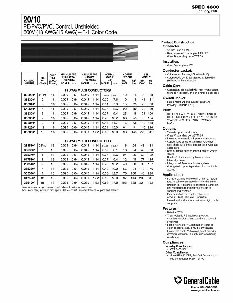
Phone: 888-593-3355www.generalcable.com
Product ConstructionConductor:
• 18 AWG and 16 AWG• Bare, annealed copper per ASTM B3• Class B stranding per ASTM B8
Insulation:• Clear Polyethylene (PE)
Conductor Jacket:• Color-coded Polyvinyl Chloride (PVC)• Color-coded per ICEA Method 1; Table E-1
(includes white and green)
Cable Core:• Conductors are cabled with non-hygroscopic
fillers as necessary, and an overall binder tape
Overall Jacket:• Flame-retardant and sunlight-resistant
Polyvinyl Chloride (PVC)
Print:• GENERAL CABLE® SUBSTATION CONTROL
CABLE X/C XXAWG CU/PE/PVC 75˚C 600V YEAR OF MFG SEQUENTIAL FOOTAGE MARK
Options:• Tinned copper conductors• Class C stranding per ASTM B8• Insulated or uninsulated ground conductors• Copper tape shield or aluminum/polymer
tape shield with tinned copper drain wire over cable core
• Bare or tinned copper braided basket weave shield
• Duralox® aluminum or galvanized steel interlocked armor
• Intergrabon® Moisture Barrier system• Corrugated copper tape shield longitudinally
applied
Applications:• For applications where environmental factors
require cable characteristics including flame-retardance, resistance to chemicals, abrasion and resistance to the harmful effects of sunlight and weather
• May be installed in ducts, cable trays, conduit, Class I Division 2 industrial hazardous locations or continuous rigid cable supports
Features:• Rated at 75˚C• Thermoplastic PE insulation provides
chemical resistance and excellent electrical properties
• Flame-retardant PVC conductor jacket is color-coded for easy circuit identification
• Flame-retardant PVC overall jacket provides abrasion, chemical, sunlight and weathering resistance
Compliances:Industry Compliances: • ICEA S-73-532Other Compliances: • Meets EPA 10 CFR, Part 261 for leachable
lead content per TCLP method
SPEC 4800January, 2007
2 Flat 18 0.025 0.64 0.045 1.14 10 15 39 58
2 18 0.025 0.64 0.045 1.14 0.30 7.6 10 15 41 61
3 18 0.025 0.64 0.045 1.14 0.31 7.9 15 23 49 73
4 18 0.025 0.64 0.045 1.14 0.34 8.6 20 30 60 89
5 18 0.025 0.64 0.045 1.14 0.37 9.4 25 38 71 106
7 18 0.025 0.64 0.045 1.14 0.40 10.2 36 53 90 134
9 18 0.025 0.64 0.045 1.14 0.46 11.7 46 68 113 168
12 18 0.025 0.64 0.045 1.14 0.51 13.0 61 91 145 216
19 18 0.025 0.64 0.060 1.52 0.63 16.0 96 143 229 341
2 Flat 16 0.025 0.64 0.045 1.14 16 24 43 84
2 16 0.025 0.64 0.045 1.14 0.32 8.1 16 24 49 73
3 16 0.025 0.64 0.045 1.14 0.34 8.6 24 36 62 92
4 16 0.025 0.64 0.045 1.14 0.37 9.4 32 48 77 115
5 16 0.025 0.64 0.045 1.14 0.40 10.2 40 60 92 137
7 16 0.025 0.64 0.045 1.14 0.43 10.9 56 84 118 176
9 16 0.025 0.64 0.045 1.14 0.50 12.7 73 108 148 220
12 16 0.025 0.64 0.060 1.52 0.59 15.0 97 144 209 311
19 16 0.025 0.64 0.060 1.52 0.69 17.5 153 228 304 452
283530*
365360*
365370*
647530*
283540*
365380*
365390*
647550*
365400*
365290*
365300*
363310*
543640*
365320*
365330*
365340*
547230*
365350*
20/10PE/PVC/PVC, Control, Unshielded600V (18 AWG/16 AWG)—E-1 Color Code
Dimensions and weights are nominal; subject to industry tolerances.*Non-stock item, minimum runs apply. Please consult Customer Service for price and delivery.
CATALOG NUMBER
NO.OF
COND
COND. SIZE AWG/kcmil
MINIMUM AVG. INSULATION THICKNESS
INCHES mm
MINIMUM AVG. JACKET
THICKNESS INCHES mm
NOMINAL CABLE
O.D.INCHES mm
COPPER WEIGHT
lbs/ kg/ 1000ft km
NET WEIGHT
lbs/ kg/ 1000ft km
18 AWG MULTI CONDUCTORS
16 AWG MULTI CONDUCTORS
( )
.21x.32 5.3x8.1
.20x.30 5.1x7.5
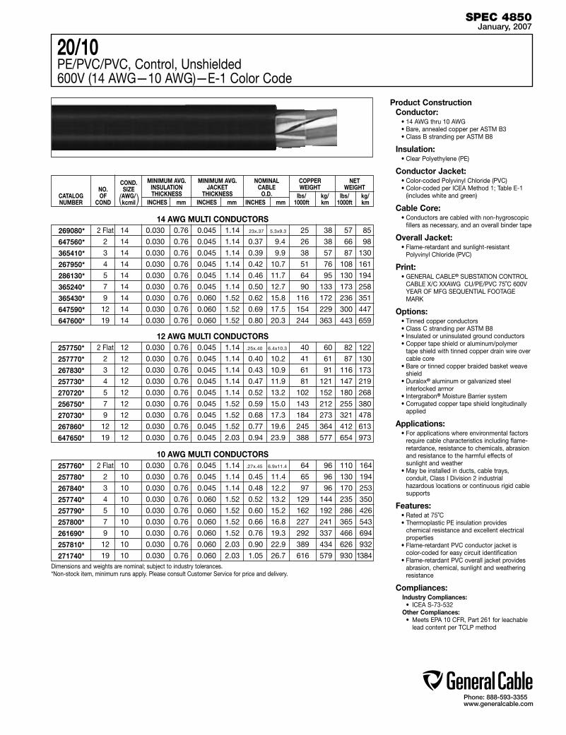
Phone: 888-593-3355www.generalcable.com
Product ConstructionConductor:
• 14 AWG thru 10 AWG• Bare, annealed copper per ASTM B3• Class B stranding per ASTM B8
Insulation:• Clear Polyethylene (PE)
Conductor Jacket:• Color-coded Polyvinyl Chloride (PVC)• Color-coded per ICEA Method 1; Table E-1
(includes white and green)
Cable Core:• Conductors are cabled with non-hygroscopic
fillers as necessary, and an overall binder tape
Overall Jacket:• Flame-retardant and sunlight-resistant
Polyvinyl Chloride (PVC)
Print:• GENERAL CABLE® SUBSTATION CONTROL
CABLE X/C XXAWG CU/PE/PVC 75˚C 600V YEAR OF MFG SEQUENTIAL FOOTAGE MARK
Options:• Tinned copper conductors• Class C stranding per ASTM B8• Insulated or uninsulated ground conductors• Copper tape shield or aluminum/polymer
tape shield with tinned copper drain wire over cable core
• Bare or tinned copper braided basket weave shield
• Duralox® aluminum or galvanized steel interlocked armor
• Intergrabon® Moisture Barrier system• Corrugated copper tape shield longitudinally
applied
Applications:• For applications where environmental factors
require cable characteristics including flame-retardance, resistance to chemicals, abrasion and resistance to the harmful effects of sunlight and weather
• May be installed in ducts, cable trays, conduit, Class I Division 2 industrial hazardous locations or continuous rigid cable supports
Features:• Rated at 75˚C• Thermoplastic PE insulation provides
chemical resistance and excellent electrical properties
• Flame-retardant PVC conductor jacket is color-coded for easy circuit identification
• Flame-retardant PVC overall jacket provides abrasion, chemical, sunlight and weathering resistance
Compliances:Industry Compliances: • ICEA S-73-532Other Compliances: • Meets EPA 10 CFR, Part 261 for leachable lead content per TCLP method
SPEC 4850January, 2007
2 Flat 10 0.030 0.76 0.045 1.14 64 96 110 164
2 10 0.030 0.76 0.045 1.14 0.45 11.4 65 96 130 194
3 10 0.030 0.76 0.045 1.14 0.48 12.2 97 96 170 253
4 10 0.030 0.76 0.060 1.52 0.52 13.2 129 144 235 350
5 10 0.030 0.76 0.060 1.52 0.60 15.2 162 192 286 426
7 10 0.030 0.76 0.060 1.52 0.66 16.8 227 241 365 543
9 10 0.030 0.76 0.060 1.52 0.76 19.3 292 337 466 694
12 10 0.030 0.76 0.060 2.03 0.90 22.9 389 434 626 932
19 10 0.030 0.76 0.060 2.03 1.05 26.7 616 579 930 1384
2 Flat 12 0.030 0.76 0.045 1.14 40 60 82 122
2 12 0.030 0.76 0.045 1.14 0.40 10.2 41 61 87 130
3 12 0.030 0.76 0.045 1.14 0.43 10.9 61 91 116 173
4 12 0.030 0.76 0.045 1.14 0.47 11.9 81 121 147 219
5 12 0.030 0.76 0.045 1.14 0.52 13.2 102 152 180 268
7 12 0.030 0.76 0.045 1.52 0.59 15.0 143 212 255 380
9 12 0.030 0.76 0.045 1.52 0.68 17.3 184 273 321 478
12 12 0.030 0.76 0.045 1.52 0.77 19.6 245 364 412 613
19 12 0.030 0.76 0.045 2.03 0.94 23.9 388 577 654 973
2 Flat 14 0.030 0.76 0.045 1.14 25 38 57 85
2 14 0.030 0.76 0.045 1.14 0.37 9.4 26 38 66 98
3 14 0.030 0.76 0.045 1.14 0.39 9.9 38 57 87 130
4 14 0.030 0.76 0.045 1.14 0.42 10.7 51 76 108 161
5 14 0.030 0.76 0.045 1.14 0.46 11.7 64 95 130 194
7 14 0.030 0.76 0.045 1.14 0.50 12.7 90 133 173 258
9 14 0.030 0.76 0.060 1.52 0.62 15.8 116 172 236 351
12 14 0.030 0.76 0.060 1.52 0.69 17.5 154 229 300 447
19 14 0.030 0.76 0.060 1.52 0.80 20.3 244 363 443 659
20/10PE/PVC/PVC, Control, Unshielded600V (14 AWG—10 AWG)—E-1 Color Code
CATALOG NUMBER
NO.OF
COND
COND. SIZE AWG/kcmil
MINIMUM AVG. INSULATION THICKNESS
INCHES mm
MINIMUM AVG. JACKET
THICKNESS INCHES mm
NOMINAL CABLE
O.D.INCHES mm
COPPER WEIGHT
lbs/ kg/ 1000ft km
NET WEIGHT
lbs/ kg/ 1000ft km
14 AWG MULTI CONDUCTORS
257750*
257770*
267830*
257730*
270720*
256750*
270730*
267860*
647650*
257760*
257780*
267840*
257740*
257790*
257800*
261690*
257810*
271740*
12 AWG MULTI CONDUCTORS
10 AWG MULTI CONDUCTORS
269080*
647560*
365410*
267950*
286130*
365240*
365430*
647590*
647600*
Dimensions and weights are nominal; subject to industry tolerances.*Non-stock item, minimum runs apply. Please consult Customer Service for price and delivery.
( )
.25x.40 6.4x10.3
.27x.45 6.9x11.4
23x.37 5.3x9.3
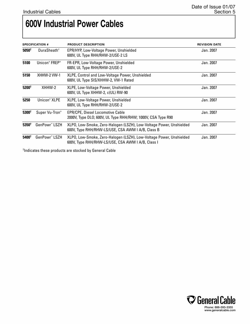
Phone: 888-593-3355www.generalcable.com
Date of Issue 01/07Industrial Cables Section 5
SPECIFICATION # PRODUCT DESCRIPTION REVISION DATE
5050† DuraSheath® EPR/HYP, Low-Voltage Power, Unshielded Jan. 2007 600V, UL Type RHH/RHW-2/USE-2 LS
5100 Unicon® FREP® FR-EPR, Low-Voltage Power, Unshielded Jan. 2007 600V, UL Type RHH/RHW-2/USE-2
5150 XHHW-2 VW-1 XLPE, Control and Low-Voltage Power, Unshielded Jan. 2007 600V, UL Type SIS/XHHW-2, VW-1 Rated
5200† XHHW-2 XLPE, Low-Voltage Power, Unshielded Jan. 2007 600V, UL Type XHHW-2, c(UL) RW-90
5250 Unicon® XLPE XLPE, Low-Voltage Power, Unshielded Jan. 2007 600V, UL Type RHH/RHW-2/USE-2
5300† Super Vu-Tron® EPR/CPE, Diesel Locomotive Cable Jan. 2007 2000V, Type DLO; 600V, UL Type RHH/RHW; 1000V, CSA Type R90
5350† GenPowr™ LSZH XLPO, Low-Smoke, Zero-Halogen (LSZH), Low-Voltage Power, Unshielded Jan. 2007 600V, Type RHH/RHW-LS/USE, CSA AWM I A/B, Class B
5400† GenPowr™ LSZH XLPO, Low-Smoke, Zero-Halogen (LSZH), Low-Voltage Power, Unshielded Jan. 2007 600V, Type RHH/RHW-LS/USE, CSA AWM I A/B, Class I
†Indicates these products are stocked by General Cable
600V Industrial Power Cables
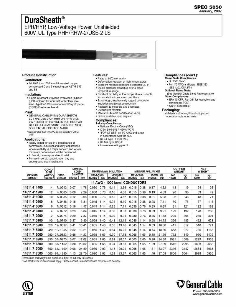
Phone: 888-593-3355www.generalcable.com
14 7/.0242 0.07 1.78 0.030 0.76 0.14 3.56 0.015 0.38 0.17 4.32 13 19 24 36
12 7/.0305 0.09 2.29 0.030 0.76 0.16 4.06 0.015 0.38 0.19 4.83 20 30 33 49
10 7/.0385 0.12 3.05 0.030 0.76 0.18 4.57 0.015 0.38 0.21 5.33 32 48 48 71
8 7/.0486 0.15 3.81 0.045 1.14 0.24 6.10 0.015 0.38 0.28 7.11 50 75 77 115
6 7/.0612 0.18 4.57 0.045 1.14 0.28 7.11 0.030 0.76 0.35 8.89 81 121 122 182
4 7/.0772 0.23 5.84 0.045 1.14 0.33 8.38 0.030 0.76 0.39 9.91 129 192 178 265
2 7/.0974 0.29 7.37 0.045 1.14 0.39 9.91 0.030 0.76 0.46 11.68 205 305 265 394
1/0 19/.0740 0.37 9.40 0.055 1.40 0.48 12.19 0.045 1.14 0.58 14.73 326 485 422 628
2/0 19/.0837 0.41 10.41 0.055 1.40 0.53 13.46 0.045 1.14 0.63 16.00 411 612 518 771
4/0 19/.1055 0.52 13.21 0.055 1.40 0.64 16.26 0.045 1.14 0.74 18.80 653 972 785 1168
250 37/.0822 0.56 14.22 0.065 1.65 0.70 17.78 0.065 1.65 0.85 21.59 772 1149 960 1429
350 37/.0973 0.67 17.02 0.065 1.65 0.81 20.57 0.065 1.65 0.96 24.38 1081 1609 1299 1933
500 37/.1162 0.80 20.32 0.065 1.65 0.94 23.88 0.065 1.65 1.09 27.69 1542 2295 1803 2683
750 61/.1109 0.98 24.89 0.080 2.03 1.15 29.21 0.065 1.65 1.31 33.27 2316 3447 2664 3965
1000 61/.1280 1.13 28.70 0.080 2.03 1.31 33.27 0.065 1.65 1.46 37.08 3806 5664 3989 5936
DuraSheath®
EPR/HYP, Low-Voltage Power, Unshielded600V, UL Type RHH/RHW-2/USE-2 LS
Product ConstructionConductor:
• 14 AWG thru 1000 kcmil tin-coated copper compressed Class B stranding per ASTM B33 and B8
Insulation:• Flame-retardant Ethylene Propylene Rubber
(EPR) colored for contrast with black low-lead Hypalon® Chlorosulfonated Polyethylene (CSPE)/Elastomer blend
Print:• GENERAL CABLE® (MI) DURASHEATH
LL TYPE USE-2 OR RHH OR RHW-2 LS VW-1 (SIZE) EP 600 VOLTS SUN RES FOR CT USE (UL) DAY/MONTH/YEAR OF MFG SEQUENTIAL FOOTAGE MARK
* Sizes smaller than 1/0 AWG do not include “FOR CT USE”
Applications:• Ideally suited for use in a broad range of
commercial, industrial and utility applications where reliability is a major concern and where maximum performance will be demanded
• In free air, raceways or direct burial• For use in aerial, conduit, open tray and
underground duct/installations
Features:• Rated at 90˚C wet or dry• Deformation-resistant at high temperatures• Excellent moisture resistance, exceeds UL 44• Stable electrical properties over a broad
temperature range• Excellent flexibility at low temperatures; suitable
for installation in sub-zero conditions• Extra-tough, mechanically rugged composite
insulation and jacket construction• Resistant to most oils and chemicals• UV/sunlight-resistant• Meets UL-44 cold bend test at -40˚C• Colors available upon request
Compliances:Industry Compliances: • National Electric Code (NEC) • ICEA S-95-658 / NEMA WC70 • “FOR CT USE” on 1/0 AWG and larger in accordance with the NEC • UL 44 Type RHH/RHW-2 • UL 854 Type USE-2 • Low-smoke rating per UL
Compliances (con’t.):Flame Tests Compliances: • UL 1581 VW-1 • For 1/0 AWG and larger: IEEE 383,
IEEE 1202/CSA FT-4Optional Flame Tests: (See General Cable Sales Representative) Other Compliances: • EPA 40 CFR, Part 261 for leachable lead
content per TCLP • OSHA acceptable
Packaging:• Material cut to length and shipped on
non-returnable wood reels
14 AWG - 1000 kcmil CONDUCTORS
CATALOG NUMBER
COND. SIZE AWG/kcmil
14511.41140014511.41120014511.41100014511.41080014511.41060014511.41040014511.71020014511.71510014511.71520014511.71540014511.71600014511.71620014511.71650014511.71700014511.717500
NOMINAL COND.
DIAMETER INCHES mm
THICKNESS INCHES mm
THICKNESS INCHES mm
DIAMETER INCHES mm
DIAMETER INCHES mm
COND.STRAND
MINIMUM AVG. INSULATION MINIMUM AVG. JACKETCOPPER WEIGHT
lbs/ kg/ 1000ft km
NET WEIGHT
lbs/ kg/ 1000ft km
Dimensions and weights are nominal; subject to industry tolerances.*Non-stock item, minimum runs apply. Please consult Customer Service for price and delivery.
( )
SPEC 5050January, 2007
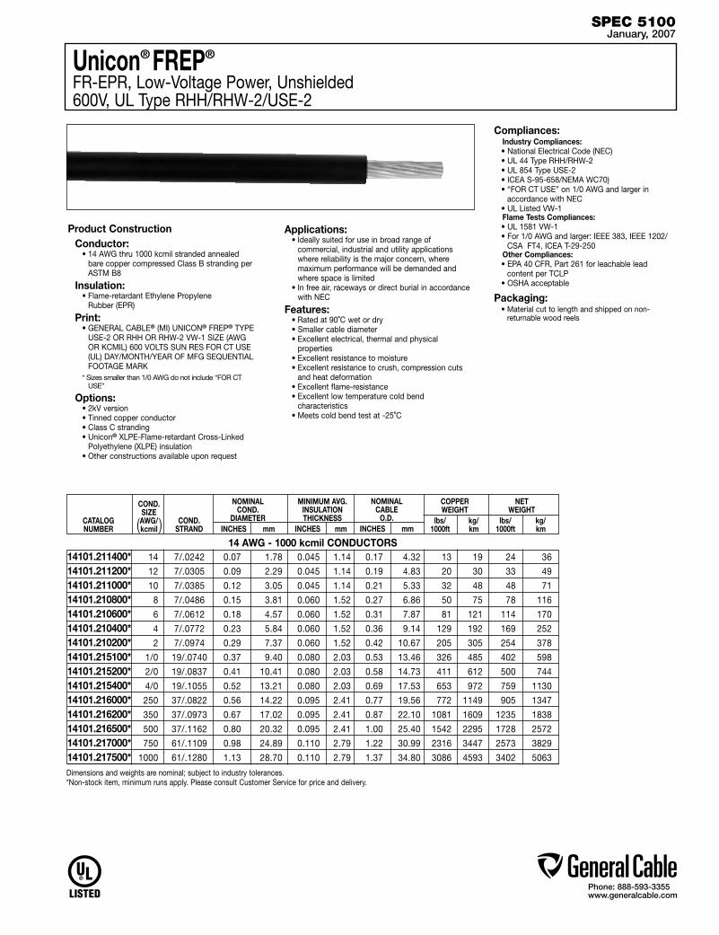
Phone: 888-593-3355www.generalcable.com
Unicon® FREP®
FR-EPR, Low-Voltage Power, Unshielded600V, UL Type RHH/RHW-2/USE-2
Product ConstructionConductor:
• 14 AWG thru 1000 kcmil stranded annealed bare copper compressed Class B stranding per
ASTM B8
Insulation:• Flame-retardant Ethylene Propylene
Rubber (EPR)
Print:• GENERAL CABLE® (MI) UNICON® FREP® TYPE
USE-2 OR RHH OR RHW-2 VW-1 SIZE (AWG OR KCMIL) 600 VOLTS SUN RES FOR CT USE (UL) DAY/MONTH/YEAR OF MFG SEQUENTIAL FOOTAGE MARK
* Sizes smaller than 1/0 AWG do not include “FOR CT USE”
Options:• 2kV version• Tinned copper conductor• Class C stranding• Unicon® XLPE-Flame-retardant Cross-Linked
Polyethylene (XLPE) insulation• Other constructions available upon request
CATALOG NUMBER
COND. SIZE AWG/kcmil
MINIMUM AVG. INSULATION THICKNESS
INCHES mm
NOMINAL COND.
DIAMETERINCHES mm
NOMINAL CABLE
O.D.INCHES mm
COPPER WEIGHT
lbs/ kg/ 1000ft km
NET WEIGHT
lbs/ kg/ 1000ft km
COND.STRAND
Applications:• Ideally suited for use in broad range of
commercial, industrial and utility applications where reliability is the major concern, where maximum performance will be demanded and where space is limited
• In free air, raceways or direct burial in accordance with NEC
Features:• Rated at 90˚C wet or dry• Smaller cable diameter• Excellent electrical, thermal and physical
properties• Excellent resistance to moisture• Excellent resistance to crush, compression cuts
and heat deformation• Excellent flame-resistance• Excellent low temperature cold bend
characteristics• Meets cold bend test at -25˚C
Compliances:Industry Compliances:• National Electrical Code (NEC)• UL 44 Type RHH/RHW-2• UL 854 Type USE-2• ICEA S-95-658/NEMA WC70)• “FOR CT USE” on 1/0 AWG and larger in
accordance with NEC• UL Listed VW-1Flame Tests Compliances: • UL 1581 VW-1• For 1/0 AWG and larger: IEEE 383, IEEE 1202/
CSA FT4, ICEA T-29-250Other Compliances: • EPA 40 CFR, Part 261 for leachable lead
content per TCLP• OSHA acceptable
Packaging:• Material cut to length and shipped on non-
returnable wood reels
( )
SPEC 5100January, 2007
14 AWG - 1000 kcmil CONDUCTORS 14 7/.0242 0.07 1.78 0.045 1.14 0.17 4.32 13 19 24 36
12 7/.0305 0.09 2.29 0.045 1.14 0.19 4.83 20 30 33 49
10 7/.0385 0.12 3.05 0.045 1.14 0.21 5.33 32 48 48 71
8 7/.0486 0.15 3.81 0.060 1.52 0.27 6.86 50 75 78 116
6 7/.0612 0.18 4.57 0.060 1.52 0.31 7.87 81 121 114 170
4 7/.0772 0.23 5.84 0.060 1.52 0.36 9.14 129 192 169 252
2 7/.0974 0.29 7.37 0.060 1.52 0.42 10.67 205 305 254 378
1/0 19/.0740 0.37 9.40 0.080 2.03 0.53 13.46 326 485 402 598
2/0 19/.0837 0.41 10.41 0.080 2.03 0.58 14.73 411 612 500 744
4/0 19/.1055 0.52 13.21 0.080 2.03 0.69 17.53 653 972 759 1130
250 37/.0822 0.56 14.22 0.095 2.41 0.77 19.56 772 1149 905 1347
350 37/.0973 0.67 17.02 0.095 2.41 0.87 22.10 1081 1609 1235 1838
500 37/.1162 0.80 20.32 0.095 2.41 1.00 25.40 1542 2295 1728 2572
750 61/.1109 0.98 24.89 0.110 2.79 1.22 30.99 2316 3447 2573 3829
1000 61/.1280 1.13 28.70 0.110 2.79 1.37 34.80 3086 4593 3402 5063
14101.211400*14101.211200*14101.211000*14101.210800*14101.210600*14101.210400*14101.210200*14101.215100*14101.215200*14101.215400*14101.216000*14101.216200*14101.216500*14101.217000*14101.217500*Dimensions and weights are nominal; subject to industry tolerances.*Non-stock item, minimum runs apply. Please consult Customer Service for price and delivery.

Phone: 888-593-3355www.generalcable.com
18 7/.0152 0.05 1.27 0.030 0.76 0.11 2.74 5.02 7.5 9.40 14
16 7/.0192 0.06 1.47 0.030 0.76 0.12 3.05 7.97 11.9 13.10 19.5
14 7/.0242 0.07 1.80 0.030 0.76 0.13 3.38 12.7 18.9 18.64 27.7
12 7/.0305 0.09 2.29 0.030 0.76 0.15 3.86 20.2 30.1 27.42 40.8
10 7/.0385 0.11 2.87 0.030 0.76 0.18 4.45 32.1 47.8 40.90 60.9
8 7/.0486 0.14 3.56 0.045 1.14 0.24 6.05 51.0 75.9 68.50 101.9
6 7/.0612 0.18 4.57 0.045 1.14 0.28 6.99 81.1 120.7 103 152.5
4 7/.0772 0.23 5.84 0.045 1.14 0.32 8.18 129 192 156 231.6
2 7/.0974 0.29 7.37 0.045 1.14 0.38 9.68 205 305.1 239 355.2
1/0 19/.0745 0.36 9.14 0.055 1.40 0.48 12.14 326 485.2 373 555.7
2/0 19/.0837 0.41 10.41 0.055 1.40 0.52 13.28 411 611.7 464 690.8
3/0 19/.0940 0.46 11.68 0.055 1.40 0.57 14.55 518 770.9 579 862.1
4/0 19/.1055 0.51 12.95 0.055 1.40 0.63 15.98 653 971.8 722 1074.5
250 37/.0822 0.56 14.22 0.065 1.65 0.70 17.75 772 1148.9 860 1279.9
350 37/.0973 0.66 16.76 0.065 1.65 0.80 20.37 1081 1608.7 1185 1763.5
500 37/.1162 0.79 20.07 0.065 1.65 0.93 23.65 1544 2297.8 1669 2483.8
Applications: • For use in power and control circuits in
switchboards, control panels and raceways in applications not exceeding 600 volts
• Acceptable for use in OSHA regulated installations
Features:• Rated at 90˚C wet or dry• UL Listed as SIS/XHHW-2¥ and XHHW-2¥¥ for
general power or control wiring in accordance with the National Electrical Code
• Sizes 1/0 and larger for CT USE• Excellent flame resistance• Sunlight-resistant• Excellent physical, thermal and electrical
properties
Compliances:Industry Compliances: • UL Type SIS/XHHW-2¥—600V • UL type XHHW-2¥¥—600V • ICEA S-95-658/NEMA WC70
• 1/0 and larger are listed “SUN RES FOR CT USE” in accordance with NECFlame Tests Compliances: • UL 44 VW-1Other Compliances: • Meets EPA 40 CFR, Part 261 for leachable lead content per TCLP method • OSHA acceptable
Packaging:• Material to be shipped on spools or non-
returnable wood reels
¥ UL Type SIS/XHHW-2 for sizes 14 AWG thru 4/0 AWG
¥¥ UL Type XHHW-2 for sizes 250 kcmil thru 500 kcmil
Product ConstructionConductor:
• 18 AWG thru 500 kcmil tinned, annealed copper per ASTM B33
• Class B stranding per ASTM B8
Insulation:• Flame-retardant Cross-Linked Polyethylene
(XLPE)• Color code: Gray
Print:For 18 AWG and 16 AWG:• GENERAL CABLE® (WC) 1C XXAWG COPPER
XLPE SIS TYPE 600V 90C YEAR OF MFGFor 14 AWG thru 4 AWG:• GENERAL CABLE® (WC) 1C XXAWG COPPER
XLPE TYPE SIS/XHHW-2 VW-1 (UL) 600V 90C YEAR OF MFG
For 2 AWG and larger:• GENERAL CABLE® (WC) 1C XXAWG COPPER
XLPE TYPE XHHW-2 VW-1 SUN RES FOR CT USE (UL) YEAR OF MFG SEQUENTIAL FOOTAGE MARK
* Sizes smaller than 1/0 AWG do not include “FOR CT USE”
XHHW-2 VW-1XLPE, Control and Low-Voltage Power, Unshielded600V, UL Type SIS1/XHHW-2, VW-1 Rated
SPEC 5150January, 2007
381500*381510*381520*381530*381540*381550*381560*381570*
06591.210200*06591.215100*06591.215200*06591.215300*06591.215400*06591.216000*06591.216200*06591.216500*
CATALOG NUMBER
COND. SIZE AWG/kcmil
NOMINAL COND.
DIAMETER INCHES mm
MINIMUM AVG. INSULATION THICKNESS
INCHES mm
NOMINAL CABLE
O.D. INCHES mm
COPPER WEIGHT
lbs/ kg/ 1000ft km
NET WEIGHT
lbs/ kg/ 1000ft km
COND.STRAND
Dimensions and weights are nominal; subject to industry tolerances.*Non-stock item, minimum runs apply. Please consult Customer Service for price and delivery.1SIS on sizes 4 AWG and smaller
( )18 AWG - 500 kcmil CONDUCTORS
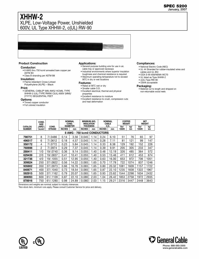
Phone: 888-593-3355www.generalcable.com
XHHW-2XLPE, Low-Voltage Power, Unshielded600V, UL Type XHHW-2, c(UL) RW-90
CATALOG NUMBER
COND. SIZE AWG/kcmil
MINIMUM AVG. INSULATION THICKNESS
INCHES mm
NOMINAL COND.
DIAMETERINCHES mm
NOMINAL CABLE
O.D.INCHES mm
COPPER WEIGHT
lbs/ kg/ 1000ft km
NET WEIGHT
lbs/ kg/ 1000ft km
COND.STRAND( )
Product ConstructionConductor:
• 8 AWG thru 750 kcmil annealed bare copper per ASTM B3
• Class B stranding per ASTM B8
Insulation:• Flame-retardant Cross-Linked
Polyethylene (XLPE) – Black
Print:• GENERAL CABLE® (MI) AWG/ KCMIL TYPE
XHHW-2 (UL) TYPE RW90 C(UL) 600V {MM}/{YYYY} SEQUENTIAL FEET
Options:• Tinned copper conductor• Full colored insulation
Applications:• General purpose building wire for use in air,
cable tray or approved raceways• Industrial environments where superior insulation
toughness and chemical resistance is required• Maximum operating temperature not to exceed
90˚C in dry or wet locations
Features:• Rated at 90˚C wet or dry• Smaller cable O.D.• Excellent electrical, thermal and physical
properties• Excellent resistance to moisture• Excellent resistance to crush, compression cuts
and heat deformation
Compliances:• National Electric Code (NEC)• UL 44 Stranded for rubber-insulated wires and
cables and UL 854• ICEA S-95-658/NEMA WC70 • UL listed as Type XHHW-2• c(UL) Type RW-90• OSHA acceptable
Packaging:• Material cut to length and shipped on
non-returnable wood reels
SPEC 5200January, 2007
8 7/.0486 0.14 3.56 0.045 1.14 0.24 6.10 51 76 65 97 6 7/.0612 0.18 4.57 0.045 1.14 0.28 7.11 81 121 99 147 4 7/.0772 0.23 5.84 0.045 1.14 0.33 8.38 129 192 152 226 2 7/.0974 0.29 7.37 0.045 1.14 0.39 9.91 205 305 233 347 1/0 19/.0740 0.36 9.14 0.055 1.40 0.48 12.19 326 485 364 572 2/0 19/.0837 0.41 10.41 0.055 1.40 0.53 13.46 411 612 453 674 4/0 19/.1055 0.51 12.95 0.055 1.40 0.63 16.00 653 972 706 1051 250 37/.0822 0.56 14.22 0.065 1.65 0.70 17.78 722 1074 837 1246 350 37/.0973 0.66 16.76 0.065 1.65 0.80 20.32 1081 1609 1157 1722 400 37/.1040 0.73 18.54 0.065 1.65 0.87 22.10 1235 1838 1322 1967 500 37/.1162 0.79 20.07 0.065 1.65 0.93 23.62 1544 2298 1634 2432 600 61/.1109 0.87 22.10 0.080 2.03 1.04 26.42 1853 2758 1972 2935 750 61/.1280 0.98 24.89 0.080 2.03 1.15 29.21 2316 3447 2448 3643
798751496517358172760698288411629439321736309824935802840671592915369093878916
Dimensions and weights are nominal; subject to industry tolerances.*Non-stock item, minimum runs apply. Please consult Customer Service for price and delivery.
8 AWG - 750 kcmil CONDUCTORS

Phone: 888-593-3355www.generalcable.com
Unicon® XLPEXLPE, Low-Voltage Power, Unshielded600V, UL Type RHH/RHW-2/USE-2
14 AWG - 1000 kcmil CONDUCTORS
CATALOG NUMBER
COND. SIZE AWG/kcmil
MINIMUM AVG. INSULATION THICKNESS
INCHES mm
NOMINAL COND.
DIAMETER INCHES mm
NOMINAL CABLE
O.D. INCHES mm
COPPER WEIGHT
lbs/ kg/ 1000ft km
NET WEIGHT
lbs/ kg/ 1000ft km
COND.STRAND( )
Dimensions and weights are nominal; subject to industry tolerances.*Non-stock item, minimum runs apply. Please consult Customer Service for price and delivery.
Product ConstructionConductor:
• 14 AWG thru 1000 kcmil stranded annealed bare copper compressed class B stranding per ASTM B8
Insulation:• Flame-retardant Cross-Linked
Polyethylene (XLPE) – Black
Print:For 14 AWG – 4 AWG:• GENERAL CABLE® (PLANT OF MFG)
UNICON®-XLP TYPE USE-2 OR RHH OR RHW-2 VW-1 SIZE (AWG OR KCMIL) 600 VOLTS SUN RES FOR CT USE (UL) DAY/MONTH/YEAR OF MFG SEQUENTIAL FOOTAGE MARK
For 2 AWG and larger:• GENERAL CABLE® (PLANT OF MFG)
UNICON®-XLP TYPE USE-2 OR RHH OR RHW-2 VW-1 (SIZE) 600 VOLTS SUN RES FOR CT USE (UL) DAY/MONTH/YEAR OF MFG SEQUENTIAL FOOTAGE MARK
* Sizes smaller than 1/0 AWG do not include “FOR CT USE”
Options:• 2 kV version• Tinned copper conductor• Class C stranding• Various colors available• Unicon® FREP®—Flame-retardant Ethylene
Propylene Rubber (EPR) insulation• Other constructions available upon request
Applications:• Ideally suited for use in a broad range of
commercial, industrial and utility applications where reliability is a major concern, where maximum performance will be demanded and where space is limited
• In free air, raceways or direct burial in accorandce with NEC
Features:• Rated at 90˚C wet or dry• Smaller cable O.D.• Excellent electrical, thermal and physical
properties
Features (con’t.):• Excellent resistance to moisture• Excellent resistance to crush, compression cuts
and heat deformation• Excellent flame resistance• Excellent low temperture cold bend
characteristics• Meets cold bend test at -25˚C
Compliances:Industry Compliances: • National Electrical Code (NEC) • ICEA S-95-658 / NEMA WC70 • “FOR CT USE” on 1/0 AWG and larger in accordance with NEC • UL 44 Type RHH/RHW-2 • UL 854 Type USE-2Flame Tests Compliances: • UL 1581 VW-1 • For 1/0 AWG and larger: IEEE 383,
IEEE 1202/CSA FT-4, ICEA T-29-520Optional Flame Tests: (See General Cable Sales Representative) Other Compliances: • EPA 40 CFR, Part 261 for leachable lead
content per TCLP • OSHA acceptable
Packaging:• Material cut to length and shipped on
non-returnable wood reels
SPEC 5250January, 2007
14 7/.0242 0.07 1.78 0.045 1.14 0.17 4.32 13 19 24 36 12 7/.0305 0.09 2.29 0.045 1.14 0.19 4.83 20 30 33 49 10 7/.0385 0.12 3.05 0.045 1.14 0.21 5.33 32 48 48 71 8 7/.0486 0.15 3.81 0.060 1.52 0.27 6.86 50 75 78 116 6 7/.0612 0.18 4.57 0.060 1.52 0.31 7.87 81 121 114 170 4 7/.0772 0.23 5.84 0.060 1.52 0.36 9.14 129 192 169 252 2 7/.0974 0.29 7.37 0.060 1.52 0.42 10.67 205 305 254 378 1/0 19/.0740 0.37 9.40 0.080 2.03 0.53 13.46 326 485 403 600 2/0 19/.0837 0.41 10.41 0.080 2.03 0.58 14.73 411 612 501 746 4/0 19/.1055 0.52 13.21 0.080 2.03 0.69 17.53 653 972 760 1131 250 37/.0822 0.56 14.22 0.095 2.41 0.77 19.56 772 1149 906 1349 350 37/.0973 0.67 17.02 0.095 2.41 0.87 22.10 1081 1609 1237 1841 500 37/.1162 0.80 20.32 0.095 2.41 1.00 25.40 1542 2295 1730 2575 750 37/.1109 0.98 24.89 0.110 2.79 1.22 30.99 2316 3447 2576 3834 1000 61/.1280 1.13 28.70 0.110 2.79 1.37 34.80 3086 4593 3405 5068
364830*364840*364850*364860*362950*364870*
16602.210200*16602.215100*16602.215200*16602.215400*16602.216000*16602.216200*16602.216500*16602.217000*16602.217500*

Phone: 888-593-3355www.generalcable.com
®
8191081908819068190481902819018191181920819308194081926819318193781944819538196481977
Super Vu-Tron®
EPR/CPE, Diesel Locomotive Cable2000V, Type DLO; 600V, UL Type RHH/RHW; 1000V, CSA Type R90
Dimensions and weights are nominal; subject to industry tolerances.*Non-stock item, minimum runs apply. Please consult Customer Service for price and delivery.(1) Ampacities based on 90˚C Conductor and 30˚C Ambient temperature based on the National Electrical Code® for not morethan three current-carrying conductors in raceway, cable or earth.(2) Ampacities based on single-conductor in free air. 90˚C conductor temperature and an ambient air temperature of 30˚C in accordance with National Electrical Code® (NEC).(S) Actual shipping weight may vary.
Product Construction: Conductor: • 10 AWG through 777.7 kcmil stranded tinned
annealed copper per AAR 589
Insulation: • Premium-grade 90˚C EP
Jacket: • Chlorinated Polyethylene (CPE), Black
Jacket Marking: • SIZES 10 THROUGH 1 AWG - CAROL SUPER
VU-TRON® (SIZE) (STRANDING) 90C DLO 2000 VOLTS P-7K-123040 MSHA CSA R90 1000V (UL) RHH OR RHW 600 VOLTS
• SIZES 1/0 THROUGH 646.4 - CAROL SUPER VU-TRON® (SIZE) 90C DLO 2000 VOLTS P-7K-123040 MSHA CSA R90 1000V (-40C) FT-1 – (UL) RHH OR RHW 600 VOLTS SUNLIGHT RESISTANT FOR CT USE NOTE: (535.3 AND 646.4 MCM PRINTED (UL) RHH OR RHW 2000 VOLTS)
• SIZE 777.7 MCM ONLY - CAROL SUPER VU-TRON® C(UL) TYPE RHW-2 2KV VW-1 FOR CT USE TYPE DLO 2000V 90C P-102 MSHA
Applications: • Diesel electric locomotives • Telecom power supply • Oil and gas drilling rigs • Mining and earth-moving equipment • Shipyards • Motor leads • Where flexible power leads must be installed in
conduit or raceways
Features: • 90˚C temperature rating • Excellent impact and abrasion resistance • Resists oils, acids, alkalies, heat, flame • Flexible tinned copper stranding • FT4 upon request
Industry Approvals: • UL Listed • Accepted for listing as flame-resistant
by MSHA • CSA R90 • RoHS Compliant
Packaging: • Lengths cut to order
CATALOGNUMBER
AWGOR MCM
COND.STRAND
NOM. INS.THICKNESS
INCHES mm INCHES mm
NOMINAL. O.D. APPROX. NET WEIGHTLBS/MFT(S)(1) (2)
CURRENTAMPS
SPEC 5300February, 2007
10
8
6
4
2
1
1/0
2/0
3/0
4/0
262.6
313.3
373.7
444.4
535.3
646.4
777.7
27/24
37/24
61/24
105/24
154/24
224/24
280/24
329/24
456/24
551/24
650/24
777/24
925/24
1110/24
1332/24
1609/24
1924/24
0.045
0.060
0.060
0.060
0.060
0.080
0.080
0.080
0.080
0.080
0.095
0.095
0.095
0.095
0.120
0.120
0.120
1.14
1.52
1.52
1.52
1.52
2.03
2.03
2.03
2.03
2.03
2.41
2.41
2.41
2.41
3.05
3.05
3.05
0.26
0.34
0.40
0.46
0.52
0.65
0.69
0.73
0.81
0.87
1.00
1.06
1.10
1.23
1.34
1.45
1.50
6.60
8.64
10.16
11.68
13.21
16.51
17.53
18.54
20.57
22.10
25.40
26.92
27.94
31.24
34.04
36.83
38.10
60
95
145
205
295
440
515
580
770
930
1130
1295
1545
1820
2195
2560
3050
40
55
75
95
130
150
170
195
225
260
296
326
362
400
445
493
546
55
80
105
140
190
220
260
300
350
405
467
522
591
652
728
815
904
10 AWG - 777.7 kcmil DLO – 2000 VOLTS

Phone: 888-593-3355www.generalcable.com
14 7/0.0242 0.07 1.78 0.045 1.14 0.17 4.32 13 19 18 27 12 7/0.0305 0.09 2.29 0.045 1.14 0.19 4.83 20 30 25 37 10 7/0.0385 0.12 3.05 0.045 1.14 0.22 5.59 32 48 38 57 8 7/0.0486 0.15 3.81 0.060 1.52 0.28 7.11 50 75 58 86 6 7/.0612 0.18 4.57 0.060 1.52 0.31 7.87 81 121 116 173 4 7/.0772 0.23 5.84 0.060 1.52 0.36 9.14 129 192 171 254 2 7/.0974 0.28 7.11 0.060 1.52 0.42 10.67 205 305 257 382 1 19/.0664 0.32 8.13 0.080 2.03 0.49 12.45 258 385 331 493 1/0 19/0.745 0.36 9.14 0.080 2.03 0.53 13.46 326 485 406 604 2/0 19/0.837 0.41 10.41 0.080 2.03 0.58 14.73 411 612 495 737 3/0 19/.0940 0.46 11.68 0.080 2.03 0.63 16.00 518 771 612 911 4/0 19/.1055 0.51 12.95 0.080 2.03 0.68 17.27 653 972 757 1126 250 37/.0822 0.56 14.22 0.095 2.41 0.76 19.30 772 1149 905 1347 350 37/.0973 0.66 16.76 0.095 2.41 0.87 22.10 1081 1609 1237 1841 500 37/.1162 0.79 20.07 0.095 2.41 1.00 25.40 1544 2298 1728 2571 750 61/.1109 0.97 24.64 0.110 2.79 1.21 30.73 2316 3447 2572 3827
COND.SIZE AWG/kcmil
MINIMUM AVG. INSULATION THICKNESS
INCHES mm
NOMINAL COND.
DIAMETERINCHES mm
NOMINAL CABLE
O.D.INCHES mm
COPPER WEIGHT
lbs/ kg/ 1000ft km
NET WEIGHT
lbs/ kg/ 1000ft km
COND.
STRAND(CLASS B)
Dimensions and weights are nominal; subject to industry tolerances.*Non-stock item, minimum runs apply. Please consult Customer Service for price and delivery.
( )
Product ConstructionConductor:
• 14 AWG thru 750 kcmil tinned coated compressed copper per ASTM B3 and B33. Class B stranding per ASTM B8.
Composite Insulation/Jacket:• Flame-retardant, oil-resistant, limited smoke,
Cross-Linked Polyolefin (XLPO)
Print:• GENERAL CABLE® (PLANT OF MFG) (UL)
TYPE USE OR RHH OR RHW-LS VW-1 (SIZE) 600V OIL RES. I SUN RES. FOR CT USE*/CSA AWM I A/B 105˚C 600V FT4 MONTH/YEAR OF MFG SEQUENTIAL FOOTAGE MARK
* Sizes smaller than 1/0 AWG do not include “FOR CT USE”
Options:• Available in Black, Blue, Green, Red and Gray
Applications:• General-purpose 600V Power Cable Applications• For use in conduit, open tray, underground duct
and aerial installations when properly supported and installed
• RHH/RHW ratings for installation in conduit or raceway
Applications (con’t.):• USE rating for Direct Burial Applications• CT-rated for installation in Cable Tray – 1/0 AWG
and larger• For use in all closed environments or populated
spaces such as auditoriums, arenas and health facilities where more stringent specifications for smoke and toxicity emission levels are desired
• Ideally suited for use in a broad range of Commercial and Industrial applications where reliability is the major concern, where maximum performance is demanded and where space is limited
Features:• UL Type RHH/RHW/USE Rated at 90˚C dry,
75˚C wet• CSA AWM I A/B Rated at 105˚C• UL AWM styles 3237 and 3578• Smooth surface for reduced coefficient of friction
for ease of installation• Excellent moisture resistance• Excellent resistance to salt water• Available in colors for ease of phase
identification• Minimum acid gas emissions under combustion• Meets cold bend test at -40˚C• Meets UL Oil Res. I and II
Compliances:• UL 44 Standard for Rubber Insulated Wire• UL 758 Standard for Appliance Wiring Material• UL 854 Standard for Service Entrance Cable• UL 1685 Standard for Vertical Tray Fire
Propagation and Smoke Release Test for Electrical and Optical Fiber Cables
• Telcordia GR347 Core• UL Listed VW-1• ICEA S-95-658/NEMA WC 70• IEEE 1202 (70,000 BTU/hr)• IEEE 383 (70,000 BTU/hr)• Sizes 1/0 AWG and larger are listed
“FOR CT USE”• CSA FT4• CSA Standard C22.2 No. 0.3• CSA Standard C22.2 No. 210.2• Meets EPA 40 CFR, Part 261 for leachable lead
content per TCLP method• OSHA acceptable
Packaging:• Material cut to length and shipped on non-
returnable wood reels
GenPower™ LSZHXLPO, Low-Smoke, Zero-Halogen (LSZH), Low-Voltage Power, Unshielded600V, Type RHH/RHW-LS/USE, CSA AWM I A/B, Class B
SPEC 5350January, 2007
14 AWG - 750 kcmil CONDUCTORS, CLASS B
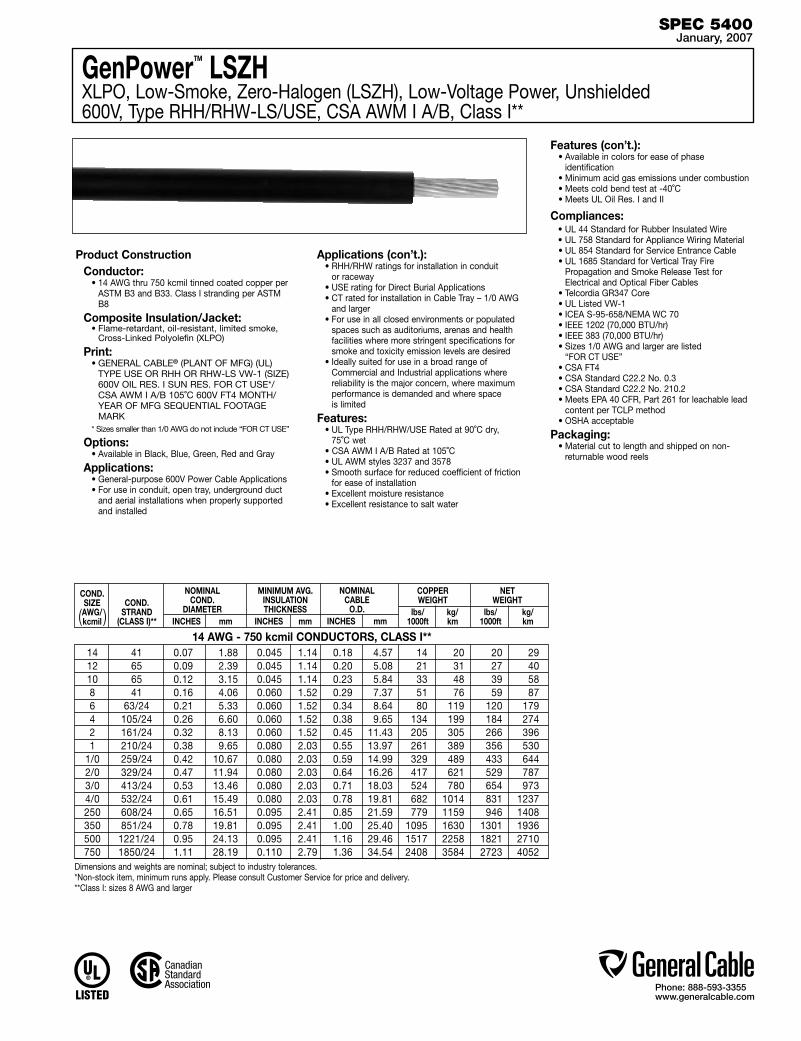
Phone: 888-593-3355www.generalcable.com
14 AWG - 750 kcmil CONDUCTORS, CLASS I**
COND.SIZE AWG/kcmil
MINIMUM AVG. INSULATION THICKNESS
INCHES mm
NOMINAL COND.
DIAMETERINCHES mm
NOMINAL CABLE
O.D.INCHES mm
COPPER WEIGHT
lbs/ kg/ 1000ft km
NET WEIGHT
lbs/ kg/ 1000ft km
COND.
STRAND(CLASS I)**
Dimensions and weights are nominal; subject to industry tolerances.*Non-stock item, minimum runs apply. Please consult Customer Service for price and delivery.**Class I: sizes 8 AWG and larger
( )
GenPower™ LSZHXLPO, Low-Smoke, Zero-Halogen (LSZH), Low-Voltage Power, Unshielded600V, Type RHH/RHW-LS/USE, CSA AWM I A/B, Class I**
Product ConstructionConductor:
• 14 AWG thru 750 kcmil tinned coated copper per ASTM B3 and B33. Class I stranding per ASTM B8
Composite Insulation/Jacket:• Flame-retardant, oil-resistant, limited smoke,
Cross-Linked Polyolefin (XLPO)
Print:• GENERAL CABLE® (PLANT OF MFG) (UL)
TYPE USE OR RHH OR RHW-LS VW-1 (SIZE) 600V OIL RES. I SUN RES. FOR CT USE*/CSA AWM I A/B 105˚C 600V FT4 MONTH/YEAR OF MFG SEQUENTIAL FOOTAGE MARK
* Sizes smaller than 1/0 AWG do not include “FOR CT USE”
Options:• Available in Black, Blue, Green, Red and Gray
Applications:• General-purpose 600V Power Cable Applications• For use in conduit, open tray, underground duct
and aerial installations when properly supported and installed
Applications (con’t.):• RHH/RHW ratings for installation in conduit or raceway• USE rating for Direct Burial Applications• CT rated for installation in Cable Tray – 1/0 AWG
and larger• For use in all closed environments or populated
spaces such as auditoriums, arenas and health facilities where more stringent specifications for smoke and toxicity emission levels are desired
• Ideally suited for use in a broad range of Commercial and Industrial applications where reliability is the major concern, where maximum performance is demanded and where space is limited
Features:• UL Type RHH/RHW/USE Rated at 90˚C dry,
75˚C wet• CSA AWM I A/B Rated at 105˚C• UL AWM styles 3237 and 3578• Smooth surface for reduced coefficient of friction
for ease of installation• Excellent moisture resistance• Excellent resistance to salt water
Features (con’t.):• Available in colors for ease of phase
identification• Minimum acid gas emissions under combustion• Meets cold bend test at -40˚C• Meets UL Oil Res. I and II
Compliances:• UL 44 Standard for Rubber Insulated Wire• UL 758 Standard for Appliance Wiring Material• UL 854 Standard for Service Entrance Cable• UL 1685 Standard for Vertical Tray Fire
Propagation and Smoke Release Test for Electrical and Optical Fiber Cables
• Telcordia GR347 Core• UL Listed VW-1• ICEA S-95-658/NEMA WC 70• IEEE 1202 (70,000 BTU/hr)• IEEE 383 (70,000 BTU/hr)• Sizes 1/0 AWG and larger are listed
“FOR CT USE”• CSA FT4• CSA Standard C22.2 No. 0.3• CSA Standard C22.2 No. 210.2• Meets EPA 40 CFR, Part 261 for leachable lead
content per TCLP method• OSHA acceptable
Packaging:• Material cut to length and shipped on non-
returnable wood reels
SPEC 5400January, 2007
14 41 0.07 1.88 0.045 1.14 0.18 4.57 14 20 20 29 12 65 0.09 2.39 0.045 1.14 0.20 5.08 21 31 27 40 10 65 0.12 3.15 0.045 1.14 0.23 5.84 33 48 39 58 8 41 0.16 4.06 0.060 1.52 0.29 7.37 51 76 59 87 6 63/24 0.21 5.33 0.060 1.52 0.34 8.64 80 119 120 179 4 105/24 0.26 6.60 0.060 1.52 0.38 9.65 134 199 184 274 2 161/24 0.32 8.13 0.060 1.52 0.45 11.43 205 305 266 396 1 210/24 0.38 9.65 0.080 2.03 0.55 13.97 261 389 356 530 1/0 259/24 0.42 10.67 0.080 2.03 0.59 14.99 329 489 433 644 2/0 329/24 0.47 11.94 0.080 2.03 0.64 16.26 417 621 529 787 3/0 413/24 0.53 13.46 0.080 2.03 0.71 18.03 524 780 654 973 4/0 532/24 0.61 15.49 0.080 2.03 0.78 19.81 682 1014 831 1237 250 608/24 0.65 16.51 0.095 2.41 0.85 21.59 779 1159 946 1408 350 851/24 0.78 19.81 0.095 2.41 1.00 25.40 1095 1630 1301 1936 500 1221/24 0.95 24.13 0.095 2.41 1.16 29.46 1517 2258 1821 2710 750 1850/24 1.11 28.19 0.110 2.79 1.36 34.54 2408 3584 2723 4052

Phone: 888-593-3355www.generalcable.com
Date of Issue 01/07Industrial Cables Section 6
2.4kV — 35kV Industrial Medium-Voltage Cables
SPECIFICATION # PRODUCT DESCRIPTION REVISION DATE
6050† DuraSheath® EPR/HYP, Medium-Voltage Power, Non-Shielded Jan. 2007 2400V, UL Type MV-90
6100† UniShield® EPR/Copper Wire Shield/CPE, Medium-Voltage Power, Shielded Jan. 2007 5kV and 8kV, UL Type MV-105, 133% / 100% Ins. Levels, 115 Mils
6150† Uniblend® EPR/Copper Tape Shield/PVC, Medium-Voltage Power, Shielded Jan. 2007 5kV and 8kV, UL Type MV-105, 133% / 100% Ins. Levels, 115 Mils
6200 Copper Wire Shield TRXLPE/Copper Wire Shield/PVC, Medium-Voltage Power Jan. 2007 5kV, UL Type MV-105, 100% Ins. Level, 90 Mils
6250 Uniblend® EPR/Copper Tape Shield with Overall PVC Jacket Jan. 2007 Medium-Voltage Power, Shielded, 5kV and 8kV, UL Type MV-105 133% / 100% Ins. Levels, 115 Mils, Three Conductor
6300† UniShield® EPR/Copper Wire Shield/CPE, Medium-Voltage Power, Shielded Jan. 2007 15kV, UL Type MV-105, 133% Ins. Level, 220 Mils
6350† Uniblend® EPR/Copper Tape Shield/PVC, Medium-Voltage Power, Shielded Jan. 2007 15kV, UL Type MV-105, 133% Ins. Level, 220 Mils
6400 Copper Wire Shield TRXLPE/Copper Wire Shield/PVC, Medium-Voltage Power Jan. 2007 15kV, UL Type MV-105, 133% Ins. Level, 220 Mils
6450 Uniblend® EPR/Copper Tape Shield with Overall PVC Jacket Jan. 2007 Medium-Voltage Power, Shielded, 15kV, UL Type MV-105 133% Ins. Level, 220 Mils, Three Conductor
6500 UniShield® EPR/Copper Wire Shield/CPE, Medium-Voltage Power, Shielded Jan. 2007 25kV and 35kV, UL Type MV-105, 133% / 100% Ins. Levels, 345 Mils
6550† Uniblend® EPR/Copper Tape Shield/PVC, Medium-Voltage Power, Shielded Jan. 2007 25kV and 35kV, UL Type MV-105, 133% / 100% Ins. Levels, 345 Mils
6600 Uniblend® EPR/Copper Tape Shield with Overall PVC Jacket Jan. 2007 Medium-Voltage Power, Shielded, 25kV and 35kV, UL Type MV-105 133% / 100% Ins. Levels, 345 Mils, Three Conductor
†Indicates these products are stocked by General Cable

Phone: 888-593-3355www.generalcable.com
Product Construction
Conductor:• 8 AWG thru 1000 kcmil annealed bare copper
compact Class B strand
Extruded Strand Shield (ESS):• Extruded thermoset semi-conducting stress-
control layer over conductor
Insulation:• Ethylene Propylene Rubber (EPR) insulation,
colored to contrast with the black jacket material
Jacket:• Low-Lead Chlorosulfonated Polyethylene
(CSPE)/Elastomer blend
Print:• GENERAL CABLE® (MI) SIZE (AWG or
KCMIL) COMPACT CU DURASHEATH® LL 2400V NONSHIELDED EP TYPE MV-90 WET OR DRY SUN RES FOR CT USE OIL RES II (UL) MONTH/YEAR OF MFG SEQUENTIAL FOOTAGE MARK
* Sizes smaller than 1/0 AWG do not include “FOR CT USE”
Options:• Multi conductor constructions• Other constructions available upon request
Applications:• Proven record of reliable performance through
extensive use in these applications: pulp and paper mills, petrochemical plants, sewage treatment facilities, water treatment plants, steel mills, textile mills, utility power generating stations, scrubbers and other environmental protections systems, railroad and mining facilities
• For use in industrial and utility applications, where ease of installation is a major concern because of limited space and exposure to personnel is minimal
• For use in wet or dry locations when installed in accordance with NEC
• For use in aerial, conduit, open tray and underground duct installations
Features:• Rated at 90˚C• Excellent heat and moisture resistance• Flexibility for easy handling• High dielectric strength• Low moisture absorption• Electrical stability under stress• Low dielectric loss• Chemical- and sunlight-resistant• Simplification of splicing and terminating by
elimination of need to handle cable shield• Extra-tough, mechanically rugged composite
insulation and jacket construction• Meets cold bend test at -35˚C
Compliances:• National Electric Code (NEC)• ICEA S-96-659/NEMA WC71• UL 1072 • FAA L824 specification for cable for
Underground Airport Lighting Circuits• UL listed as Type MV-90 for use in accordance
with NEC• Sizes 1/0 AWG and larger are listed and
marked “Sunlight-Resistant FOR CT USE” in accordance with NEC and also meet IEEE 383 (70,000 BTU/hr)
• Listed “oil-resistant II”• Meets EPA 40 CFR, Part 261 for leachable lead
content per TCLP method• OSHA acceptable
Packaging:• Material cut to length and shipped on
non-returnable wood reels
DuraSheath®
EPR/HYP, Medium-Voltage Power, Non-Shielded2400V, UL Type MV-90
SPEC 6050January, 2007
8 0.14 3.56 0.15 3.81 0.125 3.18 0.41 10.41 0.58 14.73 51 76 196 292
6 0.17 4.32 0.19 4.83 0.125 3.18 0.44 11.18 0.62 15.75 81 121 241 359
4 0.22 5.59 0.23 5.84 0.125 3.18 0.49 12.45 0.66 16.76 129 192 308 458
2 0.27 6.86 0.29 7.37 0.125 3.18 0.55 13.97 0.72 18.29 205 305 408 607
1 0.31 7.87 0.33 8.38 0.125 3.18 0.58 14.73 0.76 19.30 259 385 476 708
1/0 0.34 8.64 0.36 9.14 0.125 3.18 0.62 15.75 0.79 20.07 326 485 562 836
2/0 0.38 9.65 0.41 10.41 0.125 3.18 0.66 16.76 0.84 21.34 411 612 666 991
3/0 0.43 10.92 0.45 11.43 0.125 3.18 0.71 18.03 0.92 23.37 518 771 823 1225
4/0 0.48 12.19 0.50 12.70 0.125 3.18 0.76 19.30 0.97 24.64 653 972 983 1463
250 0.53 13.46 0.55 13.97 0.140 3.56 0.84 21.34 1.08 27.43 772 1149 1183 1761
350 0.62 15.75 0.64 16.26 0.140 3.56 0.93 23.62 1.17 29.72 1080 1607 1545 2299
500 0.74 18.80 0.77 19.56 0.140 3.56 1.06 26.92 1.30 33.02 1544 2298 2077 3091
750 0.91 23.11 0.94 23.88 0.155 3.94 1.26 32.00 1.54 39.12 2316 3447 3040 4524
1000 1.06 26.92 1.09 27.69 0.155 3.94 1.42 36.07 1.70 43.18 3086 4593 3913 5823
14901.410800* 14901.410600 14901.410400 14901.41020014901.410100*14901.415100 14901.415200 14901.415300* 14901.41540014901.416000 14901.416200 14901.416500 14901.41700014901.417500*
CATALOG NUMBER
COND.SIZE AWG/kcmil
NOMINAL CONDUCTOR
DIAMETER INCHES mm
NOMINAL EXTRUDED STRAND SHIELD
DIAMETER INCHES mm
COPPER WEIGHT
lbs/ kg/ 1000ft km
NET WEIGHT
lbs/ kg/ 1000ft km
NOMINALINSULATIONDIAMETER
INCHES mm
NOMINALINSULATIONTHICKNESS
INCHES mm
NOMINALCABLE
O.D. INCHES mm
Dimensions and weights are nominal; subject to industry tolerances.*Non-stock item, minimum runs apply. Please consult Customer Service for price and delivery.
( )2400V, UL TYPE MV-90

Phone: 888-593-3355www.generalcable.com
Product Construction
Conductor:• 2 AWG thru 1000 kcmil annealed bare copper
compact Class B strand
Extruded Strand Shield (ESS):• Extruded thermoset semi-conducting stress-
control layer over conductor
Insulation:• Ethylene Propylene Rubber (EPR) insulation
colored to contrast with black conducting shield layers
Composite Insulation Shield and Jacket:
• Six corrugated copper drain wires embedded in composite layers of semi-conducting thermoset copolymer and semi-conducting black flame-retardant Chlorinated Polyethylene (CPE)
Print:• GENERAL CABLE® (DI) (MO/YR OF
MANUFACTURE) LIGHTNING BOLT SYMBOL 1/C SIZE (AWG OR KCMIL) COMPACT CU UNISHIELD® (INSULATION THICKNESS) EPR DRTP SEMI-CON CPE JKT TYPE MV- 105 (VOLTAGE) KV% INSULATION LEVEL SUN RES FOR CT USE (UL) SEQUENTIAL FOOTAGE MARK
* Sizes smaller than 1/0 AWG do not include “FOR CT USE”
Applications:• Installed in a broad range of commercial,
industrial and utility projects such as pulp and paper mills, petrochemical plants, steel mills, textile mills, water and sewage treatment facilities, environmental protection systems, railroads, mines and fossil fuel utility generating stations
• Suitable for use in wet or dry locations when installed in accordance with NEC
• For use in aerial, conduit, open tray and underground duct installations
Features:• Rated at 105˚C• Reduced conductor size and shield system
provides the smallest premium medium-voltage shielded power cable with full insulation
• Smaller outside dimensions reduce the size of duct needed or increase the ampacity per duct
• All features contribute to faster and easier installation
• Superior cold bend and cold impact performance
• Stable and constant shield short circuit performance
• Excellent heat and moisture resistance• Outstanding corona resistance• Flexibility for easy handling
Features (con’t):• High dielectric strength• Low dielectric loss• Low moisture absorption• Electrical stability under stress• Chemical-resistant• Sunlight-resistant• Meets cold bend test at -55˚C
Compliances:• National Electrical Code (NEC)• UL 1072• ICEA S-93-639/NEMA WC74 • ICEA S-97-682• AEIC CS8• UL listed as Type MV-105 for use in
accordance with NEC• Sizes 1/0 AWG and larger are listed and
marked “Sunlight-Resistant FOR CT USE” in accordance with NEC
• IEEE 1202 (70,000 BTU/hr) /CSA FT4• Meets EPA 40 CFR, Part 2671 for leachable
lead content per TCLP method• OSHA acceptableOptional Flame Tests:• ICEA T-29-520 (210,000 BTU/hr)
Packaging:• Material cut to length and shipped on non-
returnable wood reels. Lengths in excess of 10,000 lbs. are provided on returnable steel reels that require a deposit
• Extra charges apply for cuts less than 1000 ft., lagging, pulling eyes, paralleling and triplexing
UniShield®
EPR/Copper Wire Shield/CPE, Medium-Voltage Power, Shielded 5kV and 8kV, UL Type MV-105, 133% / 100% Ins. Levels, 115 Mils
SPEC 6100January, 2007
5kV AND 8kV, UL TYPE MV-105, 133% / 100% INS. LEVELS, 115 MILS
CATALOG NUMBER
CONDUIT SIZING (3)(INCHES)
COND. SIZE AWG/kcmil
NOMINAL CONDUCTOR
DIAMETERINCHES
INSULATION DIAMETER
INCHES MIN. MAX.
COPPER WEIGHT
lbs/1000ft kg/km
NOMINAL CABLE DIAMETER WEIGHT INCHES mm lbs/1000ft kg/km
AMPACITY
Conduit Underground In Air (1) Duct (2)
DRAIN WIRESIZEAWG ( )
2 0.27 0.510 0.590 20 0.71 18.03 404 601 225 335 165 165 2.5
1/0 0.34 0.580 0.655 20 0.78 19.81 555 825 346 515 215 215 2.5
2/0 0.38 0.620 0.695 19 0.83 21.08 666 990 436 649 255 245 3
3/0 0.43 0.665 0.745 19 0.88 22.35 791 1177 562 808 290 275 3
4/0 0.48 0.720 0.795 19 0.93 23.62 951 1415 678 1010 330 315 3
250 0.53 0.770 0.850 18 1.01 25.65 1112 1655 804 1196 365 345 3.5
350 0.62 0.870 0.945 18 1.11 28.19 1463 2176 1113 1656 440 415 3.5
500 0.74 0.990 1.065 17 1.24 31.50 2003 2980 1585 2358 535 500 4
750 0.91 1.170 1.250 17 1.44 36.57 2875 4278 2357 3507 655 610 5
1000 1.06 1.320 1.400 16 1.61 40.89 3746 5574 3138 4669 755 690 5
19101.65020019101.65510019101.66520019101.665300*19101.66540019101.67600019101.67620019101.68650019101.68700019101.667500*
*Non-stock item, minimum runs apply. Please consult Customer Service for price and delivery.(1) Ampacities are in accordance with Table 310-73 of the NEC for triplexed or three single conductor copper cable in isolated conduit in air, based on a conductor temperature of 105˚C (221˚F) and an ambient air temperature of 40˚C (104˚F).(2) Ampacities are in accordance with Table 310-77 of the NEC for triplexed or three single conductor copper cable in underground ducts (three conductors per duct) based on a conductor temperature of 105˚C (221˚F) and an ambient earth temperature of 20˚C (68˚F), electrical duct arrangement per Figure 310.60 Detail 1, 100% load factor, and earth thermal resistance (rho) of 90.(3) Based on nominal cable diameters, three single cables in the duct with no ground wire and a maximum of 40% fill. Jam ratio should be checked for individual installations.Dimensions and weights are nominal subject to industry tolerance.Note: a) Sizes smaller than 1/0 AWG do not include “FOR CT USE” b) The NESC Lightning bolt symbol is on all UniShield® constructions
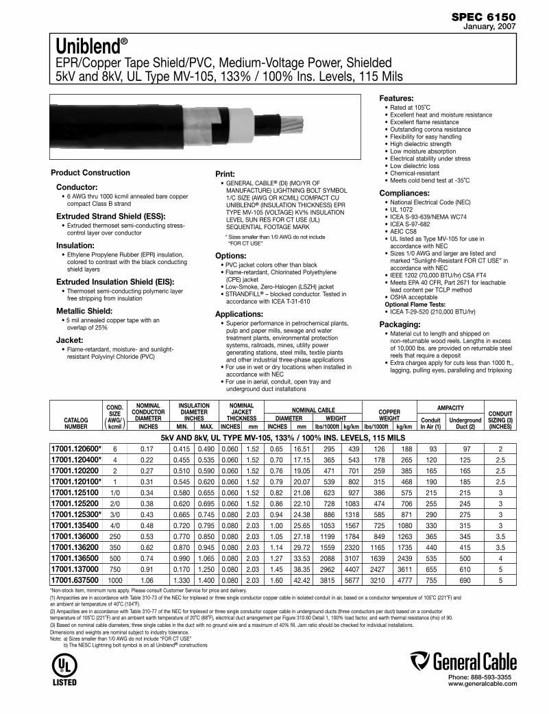
Phone: 888-593-3355www.generalcable.com
*Non-stock item, minimum runs apply. Please consult Customer Service for price and delivery.(1) Ampacities are in accordance with Table 310-73 of the NEC for triplexed or three single conductor copper cable in isolated conduit in air, based on a conductor temperature of 105˚C (221˚F) and an ambient air temperature of 40˚C (104˚F).(2) Ampacities are in accordance with Table 310-77 of the NEC for triplexed or three single conductor copper cable in underground ducts (three conductors per duct) based on a conductor temperature of 105˚C (221˚F) and an ambient earth temperature of 20˚C (68˚F), electrical duct arrangement per Figure 310.60 Detail 1, 100% load factor, and earth thermal resistance (rho) of 90.(3) Based on nominal cable diameters, three single cables in the duct with no ground wire and a maximum of 40% fill. Jam ratio should be checked for individual installations. Dimensions and weights are nominal subject to industry tolerance.Note: a) Sizes smaller than 1/0 AWG do not include “FOR CT USE” b) The NESC Lightning bolt symbol is on all Uniblend® constructions
Uniblend®
EPR/Copper Tape Shield/PVC, Medium-Voltage Power, Shielded5kV and 8kV, UL Type MV-105, 133% / 100% Ins. Levels, 115 Mils
Product Construction
Conductor:• 6 AWG thru 1000 kcmil annealed bare copper
compact Class B strand
Extruded Strand Shield (ESS):• Extruded thermoset semi-conducting stress-
control layer over conductor
Insulation: • Ethylene Propylene Rubber (EPR) insulation,
colored to contrast with the black conducting shield layers
Extruded Insulation Shield (EIS):• Thermoset semi-conducting polymeric layer
free stripping from insulation
Metallic Shield:• 5 mil annealed copper tape with an
overlap of 25%
Jacket:• Flame-retardant, moisture- and sunlight-
resistant Polyvinyl Chloride (PVC)
Print:• GENERAL CABLE® (DI) (MO/YR OF
MANUFACTURE) LIGHTNING BOLT SYMBOL 1/C SIZE (AWG OR KCMIL) COMPACT CU UNIBLEND® (INSULATION THICKNESS) EPR TYPE MV-105 (VOLTAGE) KV% INSULATION LEVEL SUN RES FOR CT USE (UL) SEQUENTIAL FOOTAGE MARK
* Sizes smaller than 1/0 AWG do not include “FOR CT USE”
Options:• PVC jacket colors other than black • Flame-retardant, Chlorinated Polyethylene
(CPE) jacket• Low-Smoke, Zero-Halogen (LSZH) jacket• STRANDFILL® – blocked conductor. Tested in
accordance with ICEA T-31-610
Applications:• Superior performance in petrochemical plants,
pulp and paper mills, sewage and water treatment plants, environmental protection systems, railroads, mines, utility power generating stations, steel mills, textile plants and other industrial three-phase applications
• For use in wet or dry locations when installed in accordance with NEC
• For use in aerial, conduit, open tray and underground duct installations
Features:• Rated at 105˚C• Excellent heat and moisture resistance• Excellent flame resistance• Outstanding corona resistance• Flexibility for easy handling• High dielectric strength• Low moisture absorption• Electrical stability under stress• Low dielectric loss• Chemical-resistant• Meets cold bend test at -35˚C
Compliances:• National Electrical Code (NEC)• UL 1072• ICEA S-93-639/NEMA WC74• ICEA S-97-682• AEIC CS8 • UL listed as Type MV-105 for use in
accordance with NEC• Sizes 1/0 AWG and larger are listed and
marked “Sunlight-Resistant FOR CT USE” in accordance with NEC
• IEEE 1202 (70,000 BTU/hr) CSA FT4 • Meets EPA 40 CFR, Part 2671 for leachable
lead content per TCLP method• OSHA acceptableOptional Flame Tests:• ICEA T-29-520 (210,000 BTU/hr)
Packaging:• Material cut to length and shipped on
non-returnable wood reels. Lengths in excess of 10,000 lbs. are provided on returnable steel reels that require a deposit
• Extra charges apply for cuts less than 1000 ft., lagging, pulling eyes, paralleling and triplexing
SPEC 6150January, 2007
5kV AND 8kV, UL TYPE MV-105, 133% / 100% INS. LEVELS, 115 MILS
CATALOG NUMBER
CONDUIT SIZING (3)(INCHES)
COND. SIZE AWG/kcmil
NOMINAL CONDUCTOR
DIAMETERINCHES
INSULATION DIAMETER
INCHES MIN. MAX.
COPPER WEIGHT
lbs/1000ft kg/km
NOMINAL CABLE DIAMETER WEIGHT INCHES mm lbs/1000ft kg/km
AMPACITY
Conduit Underground In Air (1) Duct (2)
NOMINALJACKET
THICKNESSINCHES mm( )
6 0.17 0.415 0.490 0.060 1.52 0.65 16.51 295 439 126 188 93 97 2
4 0.22 0.455 0.535 0.060 1.52 0.70 17.15 365 543 178 265 120 125 2.5
2 0.27 0.510 0.590 0.060 1.52 0.76 19.05 471 701 259 385 165 165 2.5
1 0.31 0.545 0.620 0.060 1.52 0.79 20.07 539 802 315 468 190 185 2.5
1/0 0.34 0.580 0.655 0.060 1.52 0.82 21.08 623 927 386 575 215 215 3
2/0 0.38 0.620 0.695 0.060 1.52 0.86 22.10 728 1083 474 706 255 245 3
3/0 0.43 0.665 0.745 0.080 2.03 0.94 24.38 886 1318 585 871 290 275 3
4/0 0.48 0.720 0.795 0.080 2.03 1.00 25.65 1053 1567 725 1080 330 315 3
250 0.53 0.770 0.850 0.080 2.03 1.05 27.18 1199 1784 849 1263 365 345 3.5
350 0.62 0.870 0.945 0.080 2.03 1.14 29.72 1559 2320 1165 1735 440 415 3.5
500 0.74 0.990 1.065 0.080 2.03 1.27 33.53 2088 3107 1639 2439 535 500 4
750 0.91 0.170 1.250 0.080 2.03 1.45 38.35 2962 4407 2427 3611 655 610 5
1000 1.06 1.330 1.400 0.080 2.03 1.60 42.42 3815 5677 3210 4777 755 690 5
17001.120600* 17001.120400* 17001.120200 17001.120100*17001.125100 17001.125200 17001.125300* 17001.13540017001.136000 17001.136200 17001.136500 17001.13700017001.637500

Phone: 888-593-3355www.generalcable.com
Copper Wire ShieldTRXLPE/Copper Wire Shield/PVC, Medium-Voltage Power 5kV, UL Type MV-105, 100% Ins. Level, 90 Mils
Product Construction
Conductor:• 6 AWG thru 1000 kcmil annealed bare copper
Class B compressed strand in accordance with ASTM B3 and B8
Extruded Strand Shield (ESS):• Extruded thermoset semi-conducting stress
control layer over conductor
Insulation:• Tree Retardant Cross-Linked Polyethylene
(TRXLPE)
Extruded Insulation Shield (EIS):• Thermoset semi-conducting polymeric layer
free stripping from insulation
Metallic Shield:• A concentric serve of 24 AWG annealed solid
bare copper wires over which shall be applied a lapped non-metallic tape
Jacket:• Flame-retardant, moisture- and
sunlight-resistant Polyvinyl Chloride (PVC)
Print:• GENERAL CABLE® (DI) (MO/YR OF
MANUFACTURE) LIGHTNING BOLT SYMBOL 1/C SIZE (AWG OR KCMIL) CU (INSULATION THICKNESS) TRXLPE TYPE MV-105 (VOLTAGE) KV% INSULATION LEVEL SUN RES (UL) SEQUENTIAL FOOTAGE MARK
Options:• Sizes 1/0 AWG and larger are listed and
marked “Sunlight-Resistant FOR CT USE” in accordance with NEC and in accordance with UL 1685 (70,000 BTU/hr)
• STRANDFILL® – blocked conductor. Tested in accordance with ICEA T-31-610
Applications:• For use in wet or dry locations when installed in
accordance with NEC• For use in aerial, conduit, open tray and
underground duct installations where cost effectiveness is a factor
Features:• Rated at 105˚C• Triple tandem extrusion of the strand shield,
insulation and insulation shield provides a virtually perfect cable core
• Excellent resistance to electro-chemical treeing, heat, moisture and a wide variety of industrial chemicals
• PVC jacket provides mechanical protection of the shielding system during installation, as well as protection from many industrial chemicals
• Sunlight-resistant• Meets cold bend test at -35˚C
Compliances:• National Electrical Code (NEC)• ICEA S-93-639/NEMA WC74• ICEA S-97-682• AEIC CS8• UL 1072• UL listed as Type MV-105 for use in
accordance with NEC • Meets EPA 40 CFR, Part 261 for leachable lead
content per TCLP method• OSHA acceptable
Packaging:• Material cut to length and shipped on
non-returnable wood reels. Lengths in excess of 10,000 lbs. are provided on returnable steel reels that require a deposit
• Extra charges apply for cuts less than 1000 ft., lagging, pulling eyes, paralleling and plexing
SPEC 6200January, 2007
5kV, UL TYPE MV-105, 100% INS. LEVEL, 90 MILS
CATALOG NUMBER
CONDUIT SIZING (3)(INCHES)
COND. SIZE AWG/kcmil
NOMINAL CONDUCTOR
DIAMETERINCHES
INSULATION DIAMETER
INCHES MIN. MAX.
COPPER WEIGHT
lbs/1000ft kg/km
NOMINAL CABLE DIAMETER WEIGHT INCHES mm lbs/1000ft kg/km
AMPACITY
Conduit Underground In Air (1) Duct (2)
NOMINALJACKET
THICKNESSINCHES mm( )
6 0.18 0.370 0.445 0.060 1.52 0.67 17.02 250 372 93 138 84 92 2.5
4 0.23 0.420 0.495 0.060 1.52 0.72 18.29 317 472 141 210 110 120 2.5
2 0.29 0.475 0.555 0.060 1.52 0.77 19.55 420 625 217 323 145 155 2.5
1/0 0.37 0.555 0.630 0.060 1.52 0.85 21.59 580 863 338 503 200 210 3
2/0 0.41 0.600 0.675 0.060 1.52 0.89 22.61 670 997 427 635 225 235 3
4/0 0.52 0.705 0.780 0.080 2.03 1.04 26.42 1000 1488 669 996 305 310 3.5
250 0.56 0.760 0.835 0.080 2.03 1.10 28.19 1155 1719 788 1173 355 345 3.5
350 0.67 0.865 0.940 0.080 2.03 1.20 30.48 1505 2240 1097 1632 430 415 4
500 0.80 0.990 1.070 0.080 2.03 1.36 34.54 2060 3066 1563 2325 530 505 5
750 0.97 1.180 1.255 0.080 2.03 1.53 38.86 2868 4268 2340 3482 665 630 5
1000 1.12 1.325 1.405 0.080 2.03 1.66 42.16 3684 5482 3113 4632 770 720 6
17241.010600*17241.010400*17241.010200*17241.015100*17241.015200*17241.015400*17241.016000*17241.016200*17241.016500*17241.017000*17241.017500**Non-stock item, minimum runs apply. Please consult Customer Service for price and delivery.
(1) Ampacities are in accordance with Table 310-73 of the NEC for triplexed or three single conductor copper cable in isolated conduit in air, based on a conductor temperature of 105˚C (221˚F) and an ambient air temperature of 40˚C (104˚F).
(2) Ampacities are in accordance with Table 310-77 of the NEC for triplexed or three single conductor copper cable in underground ducts (three conductors per duct) based on a conductor temperature of 105˚C (221˚F) and an ambient earth temperature of 20˚C (68˚F), electrical duct arrangement per Figure 310.60 Detail 1, 100% load factor, and earth thermal resistance (rho) of 90.
(3) Based on nominal cable diameters, three single cables in the duct with no ground wire and a maximum of 40% fill. Jam ratio should be checked for individual installations.
Dimensions and weights are nominal; subject to industry tolerances.Note: The NESC Lightning bolt symbol is on all Uniblend® constructions

Phone: 888-593-3355www.generalcable.com
Uniblend®
EPR/Copper Tape Shield with Overall PVC Jacket, Medium-Voltage Power, Shielded5kV and 8kV, UL Type MV-105, 133% / 100% Ins. Levels, 115 Mils, Three Conductor
Product Construction
Conductor:• 6 AWG thru 1000 kcmil annealed bare copper
compact Class B strand
Extruded Strand Shield (ESS):• Extruded thermoset semi-conducting stress-
control layer over conductor
Insulation:• Ethylene Propylene Rubber (EPR) insulation,
colored to contrast with the black conducting shield layers
Extruded Insulation Shield (EIS):• Thermoset semi-conducting polymeric layer
free stripping from insulation
Metallic Shield:• 5mil annealed copper tape with an
overlap of 25%
Grounding Conductor:• 1 bare grounding conductor may be in
contact with metallic shielding tape
Overall Jacket:• Flame-retardant, moisture- and sunlight-
resistant Polyvinyl Chloride (PVC)
Print: • GENERAL CABLE® (DI) (MO/YR OF
MANUFACTURE) LIGHTNING BOLT SYMBOL 3/C SIZE (AWG OR KCMIL) COMPACT CU UNIBLEND® (INSULATION THICKNESS) EPR TYPE MV-105 (VOLTAGE) KV% INSULATION LEVEL SUN RES FOR CT USE (UL) SEQUENTIAL FOOTAGE MARK
Options:• PVC jacket colors other than black• Flame-retardant, Chlorinated Polyethylene
(CPE) jacket• Low-Smoke, Zero-Halogen (LSZH) jacket• Jacketed singles• UniShield® singles• STRANDFILL® – blocked conductor. Tested in
accordance with ICEA T-31-610• 3 bare copper ground wires• Covered ground wires
Applications:• Suited for use in a broad range of
commercial, industrial and utility applications, where reliability is the major concern, space is limited and ease of installation is critical
• In wet or dry locations when installed in accordance with NEC
• In aerial, conduit, open tray and underground duct installations
Features:• Rated at 105˚C• Excellent heat and moisture resistance• Outstanding corona resistance• Flexibility for easy handling• High dielectric strength• Low moisture absorption• Electrical stability under stress• Low dielectric loss• Chemical-resistant• Meets cold bend test at -35˚C
Compliances:• National Electrical Code (NEC)• UL 1072• ICEA S-93-639/NEMA WC74 • ICEA S-97-682• AEIC CS8 • UL listed as Type MV-105 for use in
accordance with NEC• UL 1685 (70,000 BTU/hr)• Meets EPA 40 CFR, Part 261 for leachable
lead content per TCLP method• OSHA acceptableOptional Flame Tests:
• IEEE 1202 (70,000 BTU/hr)/CSA FT4• ICEA T-29-520 (210,000 BTU/hr)
Packaging:• Material cut to length and shipped on
non-returnable wood reels. Lengths in excess of 10,000 lbs. are provided on returnable steel reels that require a deposit
• Extra charges apply for cuts less than 1000 ft., lagging, pulling eyes, paralleling and plexing
SPEC 6250January, 2007
5kV AND 8kV, UL TYPE MV-105, 133% / 100% INS. LEVELS, 115 MILS, THREE CONDUCTOR
CATALOG NUMBER
NOMINAL OVERALL JKT THICKNESS
INCHES mm
COND. SIZE AWG/kcmil
NOMINAL CONDUCTOR
DIAMETERINCHES
INSULATION DIAMETER
INCHES MIN. MAX.
COPPER WEIGHT
lbs/1000ft kg/km
NOMINAL CABLE DIAMETER WEIGHT INCHES mm lbs/1000ft kg/km
AMPACITY
Conduit Underground In Air (1) Duct (2)
GROUND
WIREAWG( )
6 0.17 0.415 0.490 6 0.080 2.03 1.29 32.77 939 1397 460 685 92 95
4 0.22 0.455 0.535 6 0.080 2.03 1.39 35.31 1158 1723 616 917 120 125
2 0.27 0.510 0.590 6 0.080 2.03 1.51 38.35 1511 2249 860 1279 165 160
1/0 0.34 0.580 0.655 4 0.080 2.03 1.67 42.42 2030 3021 1290 1919 215 210
2/0 0.38 0.620 0.695 4 0.080 2.03 1.82 46.23 2449 3645 1556 2315 245 235
4/0 0.48 0.720 0.795 3 0.110 2.79 2.07 52.58 3438 5116 2344 3488 320 305
250 0.53 0.770 0.850 2 0.110 2.79 2.15 54.61 3968 5904 2759 4105 350 335
350 0.62 0.870 0.945 2 0.110 2.79 2.36 59.94 5009 7454 3713 5525 430 400
500 0.74 0.990 1.065 1 0.110 2.79 2.64 67.06 6793 10065 5191 7724 525 485
750 0.91 1.170 1.250 1/0 0.140 3.56 3.14 79.76 9833 14633 7629 11352 635 585
1000 1.06 1.330 1.400 2/0 0.140 3.56 3.48 88.39 12601 18753 10070 14985 725 660
15493.400600*15493.400400*15493.400200*15493.405100*15493.405200*15493.405400*15493.406000*15493.406200*15493.406500*15493.407000*15493.407500**Non-stock item, minimum runs apply. Please consult Customer Service for price and delivery.
(1) Ampacities are in accordance with Table 310-75 of the NEC for three conductor copper cable in isolated conduit in air, based on a conductor temperature of 105˚C (221˚F) and an ambient air temperature of 40˚C (104˚F).
(2) Ampacities are in accordance with Table 310-79 of the NEC for three conductor copper cable in underground ducts (three conductors per duct) based on a conductor temperature of 105˚C (221˚F) and an ambient earth temperature of 20˚C (68˚F), electrical duct arrangement per Figure 310.60 Detail 1, 100% load factor, and earth thermal resistance (rho) of 90.
Dimensions and weights are nominal subject to industry tolerance.Note: a) Sizes smaller than 1/0 AWG do not include “FOR CT USE” b) The NESC Lightning bolt symbol is on all Uniblend® constructions
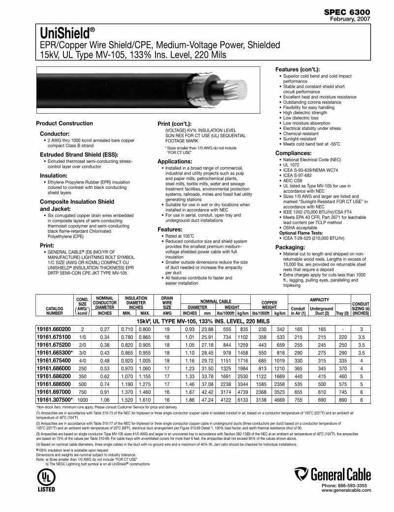
Phone: 888-593-3355www.generalcable.com
Product Construction
Conductor:• 2 AWG thru 1000 kcmil annealed bare copper
compact Class B strand
Extruded Strand Shield (ESS):• Extruded thermoset semi-conducting stress-
control layer over conductor
Insulation:• Ethylene Propylene Rubber (EPR) insulation
colored to contrast with black conducting shield layers
Composite Insulation Shield and Jacket:
• Six corrugated copper drain wires embedded in composite layers of semi-conducting thermoset copolymer and semi-conducting black flame-retardant Chlorinated Polyethylene (CPE)
Print:• GENERAL CABLE® (DI) (MO/YR OF
MANUFACTURE) LIGHTNING BOLT SYMBOL 1/C SIZE (AWG OR KCMIL) COMPACT CU UNISHIELD® (INSULATION THICKNESS) EPR DRTP SEMI-CON CPE JKT TYPE MV-105
Print (con’t.): (VOLTAGE) KV% INSULATION LEVEL
SUN RES FOR CT USE (UL) SEQUENTIAL FOOTAGE MARK
* Sizes smaller than 1/0 AWG do not include “FOR CT USE”
Applications:• Installed in a broad range of commercial,
industrial and utility projects such as pulp and paper mills, petrochemical plants, steel mills, textile mills, water and sewage treatment facilities, environmental protection systems, railroads, mines and fossil fuel utility generating stations
• Suitable for use in wet or dry locations when installed in accordance with NEC
• For use in aerial, conduit, open tray and underground duct installations
Features:• Rated at 105˚C• Reduced conductor size and shield system
provides the smallest premium medium-voltage shielded power cable with full insulation
• Smaller outside dimensions reduce the size of duct needed or increase the ampacity per duct
• All features contribute to faster and easier installation
Features (con’t.):• Superior cold bend and cold impact
performance• Stable and constant shield short
circuit performance• Excellent heat and moisture resistance• Outstanding corona resistance• Flexibility for easy handling• High dielectric strength• Low dielectric loss• Low moisture absorption• Electrical stability under stress• Chemical-resistant• Sunlight-resistant• Meets cold bend test at -55˚C
Compliances:• National Electrical Code (NEC)• UL 1072• ICEA S-93-639/NEMA WC74 • ICEA S-97-682• AEIC CS8• UL listed as Type MV-105 for use in
accordance with NEC• Sizes 1/0 AWG and larger are listed and
marked “Sunlight-Resistant FOR CT USE” in accordance with NEC
• IEEE 1202 (70,000 BTU/hr)/CSA FT4• Meets EPA 40 CFR, Part 2671 for leachable
lead content per TCLP method• OSHA acceptableOptional Flame Tests:• ICEA T-29-520 (210,000 BTU/hr)
Packaging:• Material cut to length and shipped on non-
returnable wood reels. Lengths in excess of 10,000 lbs. are provided on returnable steel reels that require a deposit
• Extra charges apply for cuts less than 1000 ft., lagging, pulling eyes, paralleling and triplexing
UniShield®
EPR/Copper Wire Shield/CPE, Medium-Voltage Power, Shielded 15kV, UL Type MV-105, 133% Ins. Level, 220 Mils
SPEC 6300February, 2007
15kV¥, UL TYPE MV-105, 133% INS. LEVEL, 220 MILS
CATALOG NUMBER
CONDUIT SIZING (4)(INCHES)
COND. SIZE AWG/kcmil
NOMINAL CONDUCTOR
DIAMETERINCHES
INSULATION DIAMETER
INCHES MIN. MAX.
COPPER WEIGHT
lbs/1000ft kg/km
NOMINAL CABLE DIAMETER WEIGHT INCHES mm lbs/1000ft kg/km
AMPACITY
Conduit Underground In Air (1) Duct (2) Tray (3)
DRAIN WIRESIZEAWG( )
2 0.27 0.710 0.800 19 0.93 23.88 555 835 230 342 165 165 - 3
1/0 0.34 0.780 0.865 18 1.01 25.91 734 1102 358 533 215 215 220 3.5
2/0 0.38 0.820 0.905 18 1.05 27.18 844 1259 443 659 255 245 250 3.5
3/0 0.43 0.865 0.955 18 1.10 28.45 978 1458 550 818 290 275 290 3.5
4/0 0.48 0.920 1.005 18 1.16 29.72 1151 1716 685 1019 330 315 335 4
250 0.53 0.970 1.060 17 1.23 31.50 1325 1984 813 1210 365 345 370 4
350 0.62 1.070 1.155 17 1.33 33.78 1691 2530 1122 1669 440 415 460 5
500 0.74 1.190 1.275 17 1.46 37.08 2238 3344 1585 2358 535 500 575 5
750 0.91 1.370 1.460 16 1.67 42.42 3174 4739 2368 3523 655 610 745 6
1000 1.06 1.520 1.610 16 1.86 47.24 4122 6133 3138 4669 755 690 890 6
19161.66020019161.67510019161.67520019161.665300*19161.67540019161.68600019161.68620019161.68650019161.69700019161.307500**Non-stock item, minimum runs apply. Please consult Customer Service for price and delivery.
(1) Ampacities are in accordance with Table 310-73 of the NEC for triplexed or three single conductor copper cable in isolated conduit in air, based on a conductor temperature of 105˚C (221˚F) and an ambient air temperature of 40˚C (104˚F).
(2) Ampacities are in accordance with Table 310-77 of the NEC for triplexed or three single conductor copper cable in underground ducts (three conductors per duct) based on a conductor temperature of 105˚C (221˚F) and an ambient earth temperature of 20˚C (68˚F), electrical duct arrangement per Figure 310.60 Detail 1, 100% load factor, and earth thermal resistance (rho) of 90.
(3) Ampactites are based on single conductor Type MV-105 sizes #1/0 AWG and larger in an uncovered tray in accordance with Section 392-13(B) of the NEC at an ambient air temperature of 40˚C (104˚F), the ampacities are based on 75% of the values per Table 310-69. For cable trays with unventilated covers for more than 6 feet, the ampacities shall not exceed 95% of the values shown above.
(4) Based on nominal cable diameters, three single cables in the duct with no ground wire and a maximum of 40% fill. Jam ratio should be checked for individual installations.¥100% insulation level is avaliable upon request Dimensions and weights are nominal subject to industry tolerance. Note: a) Sizes smaller than 1/0 AWG do not include “FOR CT USE” b) The NESC Lightning bolt symbol is on all UniShield® constructions

Phone: 888-593-3355www.generalcable.com
Uniblend®
EPR/Copper Tape Shield/PVC, Medium-Voltage Power, Shielded15kV, UL Type MV-105, 133% Ins. Level, 220 Mils
Product Construction
Conductor:• 2 AWG thru 1000 kcmil annealed bare copper
compact Class B strand
Extruded Strand Shield (ESS):• Extruded thermoset semi-conducting stress-
control layer over conductor
Insulation: • Ethylene Propylene Rubber (EPR) insulation,
colored to contrast with the black conducting shield layers
Extruded Insulation Shield (EIS):• Thermoset semi-conducting polymeric layer
free stripping from insulation
Metallic Shield:• 5 mil annealed copper tape with an
overlap of 25%
Jacket:• Flame-retardant, moisture- and sunlight-
resistant Polyvinyl Chloride (PVC)
Print:• GENERAL CABLE® (DI) (MO/YR OF
MANUFACTURE) LIGHTNING BOLT SYMBOL 1/C SIZE (AWG OR KCMIL) COMPACT CU UNIBLEND® (INSULATION THICKNESS) EPR TYPE MV-105 (VOLTAGE) KV% INSULATION LEVEL SUN RES FOR CT USE (UL) SEQUENTIAL FOOTAGE MARK
* Sizes smaller than 1/0 AWG do not include “FOR CT USE”
Options:• PVC jacket colors other than black • Flame-retardant, Chlorinated Polyethylene
(CPE) jacket• Low-Smoke, Zero-Halogen (LSZH) jacket• STRANDFILL® – blocked conductor. Tested in
accordance with ICEA T-31-610• 100% insulation level
Applications:• Superior performance in petrochemical plants,
pulp and paper mills, sewage and water treatment plants, environmental protection systems, railroads, mines, utility power generating stations, steel mills, textile plants and other industrial three-phase applications
• For use in wet or dry locations when installed in accordance with NEC
• For use in aerial, conduit, open tray and underground duct installations
Features:• Rated at 105˚C• Excellent heat and moisture resistance• Excellent flame resistance• Outstanding corona resistance• Flexibility for easy handling• High dielectric strength• Low moisture absorption• Electrical stability under stress• Low dielectric loss• Chemical-resistant• Meets cold bend test at -35˚C
Compliances:• National Electrical Code (NEC)• UL 1072• ICEA S-93-639/NEMA WC74• ICEA S-97-682• AEIC CS8 • UL listed as Type MV-105 for use in
accordance with NEC• Sizes 1/0 AWG and larger are listed and
marked “Sunlight-Resistant FOR CT USE” in accordance with NEC
• IEEE 1202 (70,000 BTU/hr) CSA FT4 • Meets EPA 40 CFR, Part 2671 for leachable
lead content per TCLP method• OSHA acceptableOptional Flame Tests:• ICEA T-29-520 (210,000 BTU/hr)
Packaging:• Material cut to length and shipped on
non-returnable wood reels. Lengths in excess of 10,000 lbs. are provided on returnable steel reels that require a deposit
• Extra charges apply for cuts less than 1000 ft., lagging, pulling eyes, paralleling and triplexing
SPEC 6350January, 2007
15kV¥, UL TYPE MV-105, 133% INS. LEVEL, 220 MILS
CATALOG NUMBER
CONDUIT SIZING (4)(INCHES)
COND. SIZE AWG/kcmil
NOMINAL CONDUCTOR
DIAMETERINCHES
INSULATION DIAMETER
INCHES MIN. MAX.
COPPER WEIGHT
lbs/1000ft kg/km
NOMINAL CABLE DIAMETER WEIGHT INCHES mm lbs/1000ft kg/km
AMPACITY
Conduit Underground In Air (1) Duct (2) Tray (3)
NOMINALJACKET
THICKNESSINCHES mm( )
2 0.27 0.710 0.800 0.080 2.03 0.99 25.14 658 979 276 411 165 165 - 3
1 0.31 0.745 0.830 0.080 2.03 1.02 25.91 733 1090 332 494 190 185 - 3.5
1/0 0.34 0.780 0.865 0.080 2.03 1.06 26.92 825 1228 403 600 215 215 220 3.5
2/0 0.38 0.820 0.905 0.080 2.03 1.10 27.94 938 1396 492 732 255 245 250 3.5
3/0 0.43 0.865 0.955 0.080 2.03 1.14 28.95 1078 1604 603 897 290 275 290 3.5
4/0 0.48 0.920 1.005 0.080 2.03 1.21 30.73 1261 1876 743 1105 330 315 335 3.5
250 0.53 0.970 1.060 0.080 2.03 1.25 31.75 1407 2093 866 1289 365 345 370 4
350 0.62 1.070 1.155 0.080 2.03 1.35 34.29 1783 2653 1184 1761 440 415 460 5
500 0.74 1.190 1.275 0.080 2.03 1.47 37.34 2331 3468 1657 2466 535 500 575 5
750 0.91 1.370 1.460 0.080 2.03 1.65 41.91 3234 4812 2445 3638 655 610 745 6
1000 1.06 1.520 1.610 0.110 2.79 1.86 47.24 4219 6278 3228 4803 755 690 890 6
17031.13020017031.130100*17031.13510017031.13520017031.135300*17031.13540017031.13600017031.13620017031.13650017031.13700017031.137500*Non-stock item, minimum runs apply. Please consult Customer Service for price and delivery.(1) Ampacities are in accordance with Table 310-73 of the NEC for triplexed or three single conductor copper cable in isolated conduit in air, based on a conductor temperature of 105˚C (221˚F) and an ambient air temperature of 40˚C (104˚F).(2) Ampacities are in accordance with Table 310-77 of the NEC for triplexed or three single conductor copper cable in underground ducts (three conductors per duct) based on a conductor temperature of 105˚C (221˚F) and an ambient earth temperature of 20˚C (68˚F), electrical duct arrangement per Figure 310.60 Detail 1, 100% load factor, and earth thermal resistance (rho) of 90.(3) Ampactites are based on single conductor Type MV-105 sizes #1/0 AWG and larger in an uncovered tray in accordance with Section 392-13(B) of the NEC at an ambient air temperature of 40˚C (104˚F), the ampacities are based on 75% of the values per Table 310-69. For cable trays with unventilated covers for more than 6 feet, the ampacities shall not exceed 95% of the values shown above.(4) Based on nominal cable diameters, three single cables in the duct with no ground wire and a maximum of 40% fill. Jam ratio should be checked for individual installations.¥100% insulation level is avaliable upon request Dimensions and weights are nominal subject to industry tolerance. Note: a) Sizes smaller than 1/0 AWG do not include “FOR CT USE” b) The NESC Lightning bolt symbol is on all Uniblend® constructions

Phone: 888-593-3355www.generalcable.com
Product Construction
Conductor:• 2 AWG thru 1000 kcmil annealed bare copper,
Class B compressed strand in accordance with ASTM B3 and B8
Extruded Strand Shield (ESS):• Extruded thermoset semi-conducting stress-
control layer over conductor
Insulation:• Tree Retardant Cross-Linked Polyethylene
(TRXLPE)
Extruded Insulation Shield (EIS):• Thermoset semi-conducting polymeric layer
free stripping from insulation
Metallic Shield:• A concentric serve of 24 AWG annealed solid
bare copper wires over which shall be applied a lapped non-metallic tape
Jacket:• Flame-retardant, moisture- and
sunlight-resistant Polyvinyl Chloride (PVC)
Print:• GENERAL CABLE® (DI) (MO/YR OF
MANUFACTURE) LIGHTNING BOLT SYMBOL 1/C SIZE (AWG OR KCMIL) CU (INSULATION THICKNESS) TRXLPE TYPE MV-105 (VOLTAGE) KV% INSULATION LEVEL SUN RES (UL) SEQUENTIAL FOOTAGE MARK
Options:• Sizes 1/0 AWG and larger are listed and
marked “Sunlight-Resistant FOR CT USE” in accordance with NEC and in accordance with UL 1685 (70,000 BTU/hr)
• STRANDFILL® – blocked conductor. Tested in accordance with ICEA T-31-610
Applications:• For use in wet or dry locations when installed
in accordance with NEC• For use in aerial, conduit, open tray and
underground duct installations where cost effectiveness is a factor
Features:• Rated at 105˚C• Triple tandem extrusion of the strand shield,
insulation and insulation shield provides a virtually perfect cable core
Features (con’t):• Excellent resistance to electro-chemical
treeing, heat, moisture and a wide variety of industrial chemicals
• PVC jacket provides mechanical protection of the shielding system during installation as well as protection from many industrial chemicals
• Sunlight-resistant• Meets cold bend test at -35˚C
Compliances:• National Electrical Code (NEC)• ICEA S-93-639/NEMA WC74 • ICEA S-97-682• AEIC CS8• UL 1072• UL listed as Type MV-105 for use in
accordance with NEC• Meets EPA 40 CFR, Part 261 for leachable
lead content per TCLP method• OSHA acceptable
Packaging:• Material cut to length and shipped on non-
returnable wood reels. Lengths in excess of 10,000 lbs. are provided on returnable steel reels that require a deposit
• Extra charges apply for cuts less than 1000 ft., lagging, pulling eyes, paralleling and triplexing
Copper Wire ShieldTRXLPE/Copper Wire Shield/PVC, Medium-Voltage Power 15kV, UL Type MV-105, 133% Ins. Level, 220 Mils
SPEC 6400January, 2007
15kV¥, UL TYPE MV-105, 133% INS. LEVEL, 220 MILS
CATALOG NUMBER
CONDUIT SIZING (4)(INCHES)
COND. SIZE AWG/kcmil
NOMINAL CONDUCTOR
DIAMETERINCHES
INSULATION DIAMETER
INCHESMIN. MAX.
COPPER WEIGHT
lbs/1000ft kg/km
NOMINAL CABLE DIAMETER WEIGHT INCHES mm lbs/1000ft kg/km
AMPACITY
Conduit Underground In Air (1) Duct (2) Tray (3)
NOMINALJACKET
THICKNESS INCHES mm( )
2 0.29 0.725 0.815 0.080 2.03 1.05 26.67 600 893 221 329 165 165 - 3.5
1 0.33 0.765 0.855 0.080 2.03 1.09 27.68 671 998 274 408 190 185 – 3.5
1/0 0.37 0.805 0.895 0.080 2.03 1.13 28.27 761 1132 342 509 215 215 220 3.5
2/0 0.41 0.850 0.935 0.080 2.03 1.18 29.97 871 1296 427 635 255 245 250 4
4/0 0.52 0.955 1.045 0.080 2.03 1.29 32.76 1179 1754 672 1000 330 315 335 4
250 0.56 1.010 1.100 0.080 2.03 1.34 34.03 1327 1974 791 1177 365 345 370 5
350 0.67 1.115 1.200 0.080 2.03 1.45 36.83 1700 2529 1105 1644 440 415 460 5
500 0.80 1.240 1.330 0.080 2.03 1.57 39.87 2236 3327 1568 2333 535 500 575 5
750 0.97 1.430 1.520 0.110 2.79 1.82 46.23 3225 4798 2344 3488 655 610 745 6
1000 1.12 1.575 1.670 0.110 2.79 1.97 50.04 4090 6086 3114 4634 755 690 890 6
17245.010200*17245.010100*17245.015100*17245.015200*17245.015400*17245.016000*17245.016200*17245.016500*17245.017000*17245.017500**Non-stock item, minimum runs apply. Please consult Customer Service for price and delivery.
(1) Ampacities are in accordance with Table 310-73 of the NEC for triplexed or three single conductor copper cable in isolated conduit in air based on a conductor temperature of 105˚C (221˚F) and an ambient air temperature of 40˚C (104˚F).
(2) Ampacities are in accordance with Table 310-77 of the NEC for triplexed or three single conductor copper cable in underground ducts (three conductors per duct) based on a conductor temperature of 105˚C (221˚F) and an ambient earth temperature of 20˚C (68˚F), electrical duct arrangement per Figure 310.60 Detail 1, 100% load factor, and earth thermal resistance (rho) of 90.
(3) Ampactites are based on single conductor Type MV-105 sizes #1/0 AWG and larger in an uncovered tray in accordance with Section 392-13 of the NEC at an ambient air temperature of 40˚C (104˚F), the ampacities are based on 75% of the values per Table 310-69. For cable trays with unventilated covers for more than 6 feet, the ampacities shall not exceed 95% of the values shown above.
(4) Based on nominal cable diameters, three single cables in the duct with no ground wire and a maximum of 40% fill. Jam ratio should be checked for individual installations.¥100% insulation level is avaliable upon request Dimensions and weights are nominal subject to industry tolerance. Note: The NESC Lightning bolt symbol is on all Uniblend® constructions
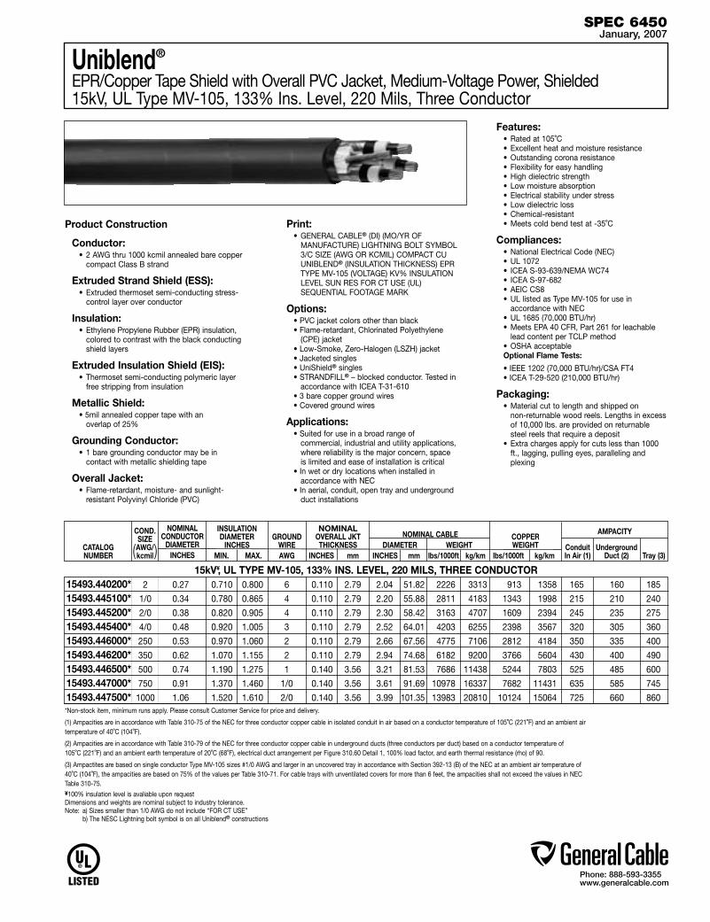
Phone: 888-593-3355www.generalcable.com
NOMINAL CONDUCTOR
DIAMETERINCHES
Uniblend®
EPR/Copper Tape Shield with Overall PVC Jacket, Medium-Voltage Power, Shielded15kV, UL Type MV-105, 133% Ins. Level, 220 Mils, Three Conductor
Product Construction
Conductor:• 2 AWG thru 1000 kcmil annealed bare copper
compact Class B strand
Extruded Strand Shield (ESS):• Extruded thermoset semi-conducting stress-
control layer over conductor
Insulation:• Ethylene Propylene Rubber (EPR) insulation,
colored to contrast with the black conducting shield layers
Extruded Insulation Shield (EIS):• Thermoset semi-conducting polymeric layer
free stripping from insulation
Metallic Shield:• 5mil annealed copper tape with an
overlap of 25%
Grounding Conductor:• 1 bare grounding conductor may be in
contact with metallic shielding tape
Overall Jacket:• Flame-retardant, moisture- and sunlight-
resistant Polyvinyl Chloride (PVC)
Print: • GENERAL CABLE® (DI) (MO/YR OF
MANUFACTURE) LIGHTNING BOLT SYMBOL 3/C SIZE (AWG OR KCMIL) COMPACT CU UNIBLEND® (INSULATION THICKNESS) EPR TYPE MV-105 (VOLTAGE) KV% INSULATION LEVEL SUN RES FOR CT USE (UL) SEQUENTIAL FOOTAGE MARK
Options:• PVC jacket colors other than black• Flame-retardant, Chlorinated Polyethylene
(CPE) jacket• Low-Smoke, Zero-Halogen (LSZH) jacket• Jacketed singles• UniShield® singles• STRANDFILL® – blocked conductor. Tested in
accordance with ICEA T-31-610• 3 bare copper ground wires• Covered ground wires
Applications:• Suited for use in a broad range of
commercial, industrial and utility applications, where reliability is the major concern, space is limited and ease of installation is critical
• In wet or dry locations when installed in accordance with NEC
• In aerial, conduit, open tray and underground duct installations
Features:• Rated at 105˚C• Excellent heat and moisture resistance• Outstanding corona resistance• Flexibility for easy handling• High dielectric strength• Low moisture absorption• Electrical stability under stress• Low dielectric loss• Chemical-resistant• Meets cold bend test at -35˚C
Compliances:• National Electrical Code (NEC)• UL 1072• ICEA S-93-639/NEMA WC74 • ICEA S-97-682• AEIC CS8 • UL listed as Type MV-105 for use in
accordance with NEC• UL 1685 (70,000 BTU/hr)• Meets EPA 40 CFR, Part 261 for leachable
lead content per TCLP method• OSHA acceptableOptional Flame Tests:
• IEEE 1202 (70,000 BTU/hr)/CSA FT4• ICEA T-29-520 (210,000 BTU/hr)
Packaging:• Material cut to length and shipped on
non-returnable wood reels. Lengths in excess of 10,000 lbs. are provided on returnable steel reels that require a deposit
• Extra charges apply for cuts less than 1000 ft., lagging, pulling eyes, paralleling and plexing
SPEC 6450January, 2007
15kV¥, UL TYPE MV-105, 133% INS. LEVEL, 220 MILS, THREE CONDUCTOR
CATALOG NUMBER
NOMINAL OVERALL JKT THICKNESS
INCHES mm
COND. SIZE AWG/kcmil
INSULATION DIAMETER
INCHES MIN. MAX.
COPPER WEIGHT
lbs/1000ft kg/km
NOMINAL CABLE DIAMETER WEIGHT INCHES mm lbs/1000ft kg/km
AMPACITY
Conduit Underground In Air (1) Duct (2) Tray (3)
GROUND
WIREAWG( )
2 0.27 0.710 0.800 6 0.110 2.79 2.04 51.82 2226 3313 913 1358 165 160 185
1/0 0.34 0.780 0.865 4 0.110 2.79 2.20 55.88 2811 4183 1343 1998 215 210 240
2/0 0.38 0.820 0.905 4 0.110 2.79 2.30 58.42 3163 4707 1609 2394 245 235 275
4/0 0.48 0.920 1.005 3 0.110 2.79 2.52 64.01 4203 6255 2398 3567 320 305 360
250 0.53 0.970 1.060 2 0.110 2.79 2.66 67.56 4775 7106 2812 4184 350 335 400
350 0.62 1.070 1.155 2 0.110 2.79 2.94 74.68 6182 9200 3766 5604 430 400 490
500 0.74 1.190 1.275 1 0.140 3.56 3.21 81.53 7686 11438 5244 7803 525 485 600
750 0.91 1.370 1.460 1/0 0.140 3.56 3.61 91.69 10978 16337 7682 11431 635 585 745
1000 1.06 1.520 1.610 2/0 0.140 3.56 3.99 101.35 13983 20810 10124 15064 725 660 860
15493.440200*15493.445100*15493.445200*15493.445400*15493.446000*15493.446200*15493.446500*15493.447000*15493.447500**Non-stock item, minimum runs apply. Please consult Customer Service for price and delivery.
(1) Ampacities are in accordance with Table 310-75 of the NEC for three conductor copper cable in isolated conduit in air based on a conductor temperature of 105˚C (221˚F) and an ambient air temperature of 40˚C (104˚F).
(2) Ampacities are in accordance with Table 310-79 of the NEC for three conductor copper cable in underground ducts (three conductors per duct) based on a conductor temperature of 105˚C (221˚F) and an ambient earth temperature of 20˚C (68˚F), electrical duct arrangement per Figure 310.60 Detail 1, 100% load factor, and earth thermal resistance (rho) of 90.
(3) Ampactites are based on single conductor Type MV-105 sizes #1/0 AWG and larger in an uncovered tray in accordance with Section 392-13 (B) of the NEC at an ambient air temperature of 40˚C (104˚F), the ampacities are based on 75% of the values per Table 310-71. For cable trays with unventilated covers for more than 6 feet, the ampacities shall not exceed the values in NEC Table 310-75.¥100% insulation level is avaliable upon request Dimensions and weights are nominal subject to industry tolerance. Note: a) Sizes smaller than 1/0 AWG do not include “FOR CT USE” b) The NESC Lightning bolt symbol is on all Uniblend® constructions
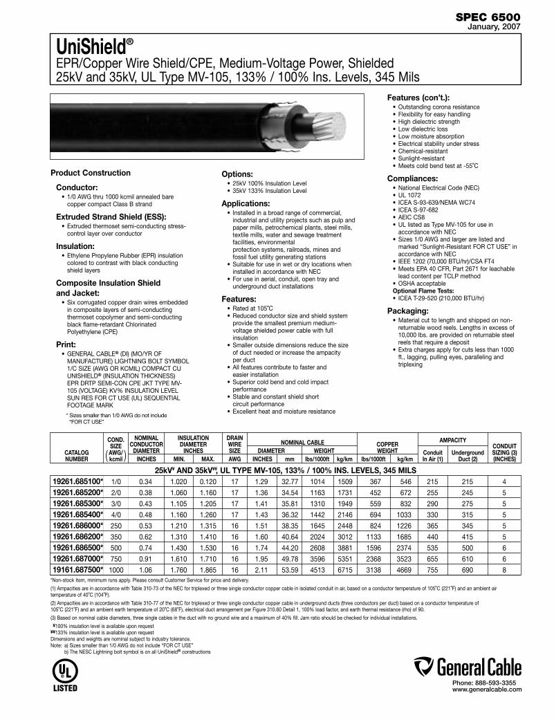
Phone: 888-593-3355www.generalcable.com
Product Construction
Conductor:• 1/0 AWG thru 1000 kcmil annealed bare
copper compact Class B strand
Extruded Strand Shield (ESS):• Extruded thermoset semi-conducting stress-
control layer over conductor
Insulation:• Ethylene Propylene Rubber (EPR) insulation
colored to contrast with black conducting shield layers
Composite Insulation Shield and Jacket:
• Six corrugated copper drain wires embedded in composite layers of semi-conducting thermoset copolymer and semi-conducting black flame-retardant Chlorinated Polyethylene (CPE)
Print:• GENERAL CABLE® (DI) (MO/YR OF
MANUFACTURE) LIGHTNING BOLT SYMBOL 1/C SIZE (AWG OR KCMIL) COMPACT CU UNISHIELD® (INSULATION THICKNESS) EPR DRTP SEMI-CON CPE JKT TYPE MV-105 (VOLTAGE) KV% INSULATION LEVEL SUN RES FOR CT USE (UL) SEQUENTIAL FOOTAGE MARK
* Sizes smaller than 1/0 AWG do not include “FOR CT USE”
Options:• 25kV 100% Insulation Level• 35kV 133% Insulation Level
Applications:• Installed in a broad range of commercial,
industrial and utility projects such as pulp and paper mills, petrochemical plants, steel mills, textile mills, water and sewage treatment facilities, environmental protection systems, railroads, mines and fossil fuel utility generating stations
• Suitable for use in wet or dry locations when installed in accordance with NEC
• For use in aerial, conduit, open tray and underground duct installations
Features:• Rated at 105˚C• Reduced conductor size and shield system
provide the smallest premium medium-voltage shielded power cable with full insulation
• Smaller outside dimensions reduce the size of duct needed or increase the ampacity per duct
• All features contribute to faster and easier installation
• Superior cold bend and cold impact performance
• Stable and constant shield short circuit performance
• Excellent heat and moisture resistance
Features (con’t.):• Outstanding corona resistance• Flexibility for easy handling• High dielectric strength• Low dielectric loss• Low moisture absorption• Electrical stability under stress• Chemical-resistant• Sunlight-resistant• Meets cold bend test at -55˚C
Compliances:• National Electrical Code (NEC)• UL 1072• ICEA S-93-639/NEMA WC74 • ICEA S-97-682• AEIC CS8• UL listed as Type MV-105 for use in
accordance with NEC• Sizes 1/0 AWG and larger are listed and
marked “Sunlight-Resistant FOR CT USE” in accordance with NEC
• IEEE 1202 (70,000 BTU/hr)/CSA FT4• Meets EPA 40 CFR, Part 2671 for leachable
lead content per TCLP method• OSHA acceptableOptional Flame Tests:• ICEA T-29-520 (210,000 BTU/hr)
Packaging:• Material cut to length and shipped on non-
returnable wood reels. Lengths in excess of 10,000 lbs. are provided on returnable steel reels that require a deposit
• Extra charges apply for cuts less than 1000 ft., lagging, pulling eyes, paralleling and triplexing
UniShield®
EPR/Copper Wire Shield/CPE, Medium-Voltage Power, Shielded 25kV and 35kV, UL Type MV-105, 133% / 100% Ins. Levels, 345 Mils
SPEC 6500January, 2007
25kV¥ AND 35kV¥¥, UL TYPE MV-105, 133% / 100% INS. LEVELS, 345 MILS
CATALOG NUMBER
CONDUIT SIZING (3)(INCHES)
COND. SIZE AWG/kcmil
NOMINAL CONDUCTOR
DIAMETERINCHES
INSULATION DIAMETER
INCHES MIN. MAX.
COPPER WEIGHT
lbs/1000ft kg/km
NOMINAL CABLE DIAMETER WEIGHT INCHES mm lbs/1000ft kg/km
AMPACITY
Conduit Underground In Air (1) Duct (2)
DRAIN WIRESIZEAWG ( )
1/0 0.34 1.020 0.120 17 1.29 32.77 1014 1509 367 546 215 215 4
2/0 0.38 1.060 1.160 17 1.36 34.54 1163 1731 452 672 255 245 5
3/0 0.43 1.105 1.205 17 1.41 35.81 1310 1949 559 832 290 275 5
4/0 0.48 1.160 1.260 17 1.43 36.32 1442 2146 694 1033 330 315 5
250 0.53 1.210 1.315 16 1.51 38.35 1645 2448 824 1226 365 345 5
350 0.62 1.310 1.410 16 1.60 40.64 2024 3012 1133 1685 440 415 5
500 0.74 1.430 1.530 16 1.74 44.20 2608 3881 1596 2374 535 500 6
750 0.91 1.610 1.710 16 1.95 49.78 3596 5351 2368 3523 655 610 6
1000 1.06 1.760 1.865 16 2.11 53.59 4513 6715 3138 4669 755 690 8
19261.685100*19261.685200*19261.685300*19261.685400*19261.686000*19261.686200*19261.686500*19261.687000*19161.687500*
*Non-stock item, minimum runs apply. Please consult Customer Service for price and delivery.
(1) Ampacities are in accordance with Table 310-73 of the NEC for triplexed or three single conductor copper cable in isolated conduit in air, based on a conductor temperature of 105˚C (221˚F) and an ambient air temperature of 40˚C (104˚F).
(2) Ampacities are in accordance with Table 310-77 of the NEC for triplexed or three single conductor copper cable in underground ducts (three conductors per duct) based on a conductor temperature of 105˚C (221˚F) and an ambient earth temperature of 20˚C (68˚F), electrical duct arrangement per Figure 310.60 Detail 1, 100% load factor, and earth thermal resistance (rho) of 90.
(3) Based on nominal cable diameters, three single cables in the duct with no ground wire and a maximum of 40% fill. Jam ratio should be checked for individual installations. ¥100% insulation level is avaliable upon request ¥¥133% insulation level is avaliable upon request Dimensions and weights are nominal subject to industry tolerance. Note: a) Sizes smaller than 1/0 AWG do not include “FOR CT USE” b) The NESC Lightning bolt symbol is on all UniShield® constructions
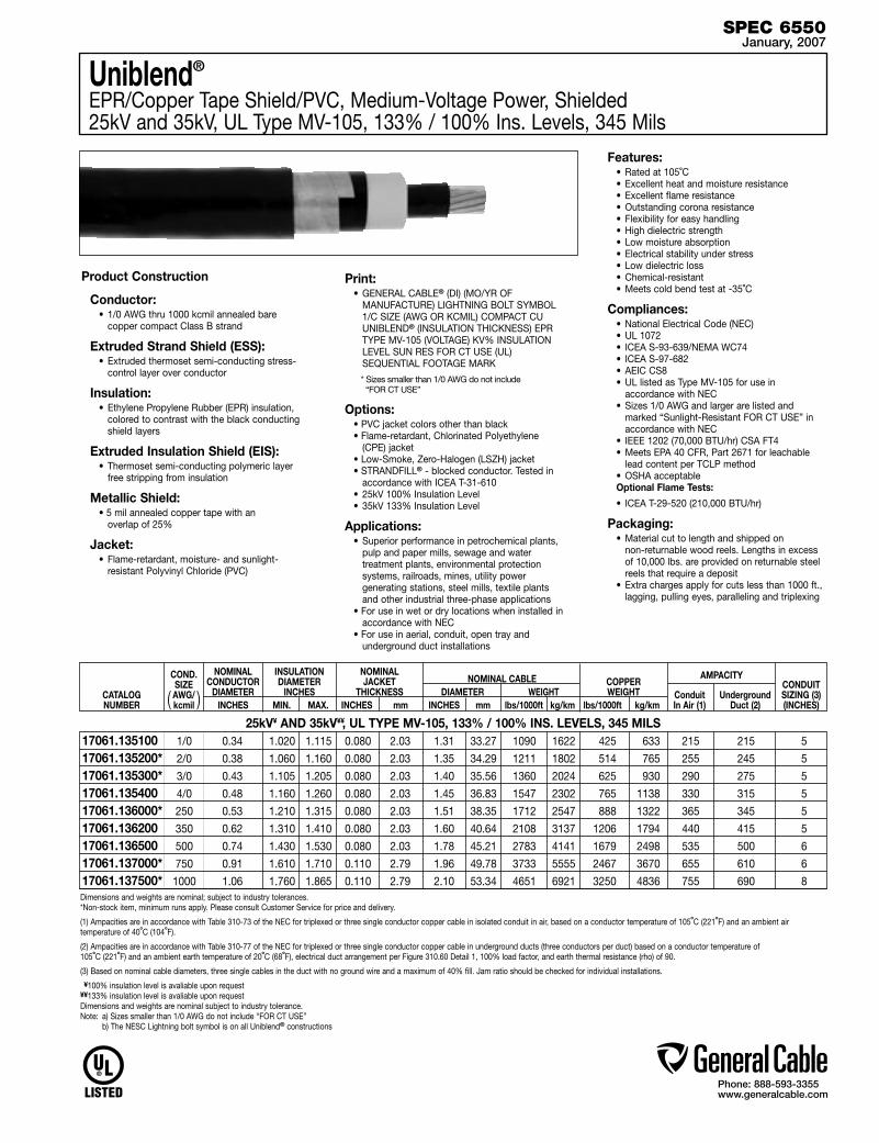
Phone: 888-593-3355www.generalcable.com
Uniblend®
EPR/Copper Tape Shield/PVC, Medium-Voltage Power, Shielded25kV and 35kV, UL Type MV-105, 133% / 100% Ins. Levels, 345 Mils
Product Construction
Conductor:• 1/0 AWG thru 1000 kcmil annealed bare
copper compact Class B strand
Extruded Strand Shield (ESS):• Extruded thermoset semi-conducting stress-
control layer over conductor
Insulation: • Ethylene Propylene Rubber (EPR) insulation,
colored to contrast with the black conducting shield layers
Extruded Insulation Shield (EIS):• Thermoset semi-conducting polymeric layer
free stripping from insulation
Metallic Shield:• 5 mil annealed copper tape with an
overlap of 25%
Jacket:• Flame-retardant, moisture- and sunlight-
resistant Polyvinyl Chloride (PVC)
Print:• GENERAL CABLE® (DI) (MO/YR OF
MANUFACTURE) LIGHTNING BOLT SYMBOL 1/C SIZE (AWG OR KCMIL) COMPACT CU UNIBLEND® (INSULATION THICKNESS) EPR TYPE MV-105 (VOLTAGE) KV% INSULATION LEVEL SUN RES FOR CT USE (UL) SEQUENTIAL FOOTAGE MARK
* Sizes smaller than 1/0 AWG do not include “FOR CT USE”
Options:• PVC jacket colors other than black • Flame-retardant, Chlorinated Polyethylene
(CPE) jacket• Low-Smoke, Zero-Halogen (LSZH) jacket• STRANDFILL® - blocked conductor. Tested in
accordance with ICEA T-31-610• 25kV 100% Insulation Level• 35kV 133% Insulation Level
Applications:• Superior performance in petrochemical plants,
pulp and paper mills, sewage and water treatment plants, environmental protection systems, railroads, mines, utility power generating stations, steel mills, textile plants and other industrial three-phase applications
• For use in wet or dry locations when installed in accordance with NEC
• For use in aerial, conduit, open tray and underground duct installations
Features:• Rated at 105˚C• Excellent heat and moisture resistance• Excellent flame resistance• Outstanding corona resistance• Flexibility for easy handling• High dielectric strength• Low moisture absorption• Electrical stability under stress• Low dielectric loss• Chemical-resistant• Meets cold bend test at -35˚C
Compliances:• National Electrical Code (NEC)• UL 1072• ICEA S-93-639/NEMA WC74• ICEA S-97-682• AEIC CS8 • UL listed as Type MV-105 for use in
accordance with NEC• Sizes 1/0 AWG and larger are listed and
marked “Sunlight-Resistant FOR CT USE” in accordance with NEC
• IEEE 1202 (70,000 BTU/hr) CSA FT4 • Meets EPA 40 CFR, Part 2671 for leachable
lead content per TCLP method• OSHA acceptableOptional Flame Tests:
• ICEA T-29-520 (210,000 BTU/hr)
Packaging:• Material cut to length and shipped on
non-returnable wood reels. Lengths in excess of 10,000 lbs. are provided on returnable steel reels that require a deposit
• Extra charges apply for cuts less than 1000 ft., lagging, pulling eyes, paralleling and triplexing
SPEC 6550January, 2007
25kV¥ AND 35kV¥¥, UL TYPE MV-105, 133% / 100% INS. LEVELS, 345 MILS
CATALOG NUMBER
CONDUIT SIZING (3)(INCHES)
COND. SIZE AWG/kcmil
NOMINAL CONDUCTOR
DIAMETERINCHES
INSULATION DIAMETER
INCHES MIN. MAX.
COPPER WEIGHT
lbs/1000ft kg/km
NOMINAL CABLE DIAMETER WEIGHT INCHES mm lbs/1000ft kg/km
AMPACITY
Conduit Underground In Air (1) Duct (2)
NOMINALJACKET
THICKNESS INCHES mm( )
1/0 0.34 1.020 1.115 0.080 2.03 1.31 33.27 1090 1622 425 633 215 215 5
2/0 0.38 1.060 1.160 0.080 2.03 1.35 34.29 1211 1802 514 765 255 245 5
3/0 0.43 1.105 1.205 0.080 2.03 1.40 35.56 1360 2024 625 930 290 275 5
4/0 0.48 1.160 1.260 0.080 2.03 1.45 36.83 1547 2302 765 1138 330 315 5
250 0.53 1.210 1.315 0.080 2.03 1.51 38.35 1712 2547 888 1322 365 345 5
350 0.62 1.310 1.410 0.080 2.03 1.60 40.64 2108 3137 1206 1794 440 415 5
500 0.74 1.430 1.530 0.080 2.03 1.78 45.21 2783 4141 1679 2498 535 500 6
750 0.91 1.610 1.710 0.110 2.79 1.96 49.78 3733 5555 2467 3670 655 610 6
1000 1.06 1.760 1.865 0.110 2.79 2.10 53.34 4651 6921 3250 4836 755 690 8
17061.135100 17061.135200* 17061.135300* 17061.13540017061.136000* 17061.136200 17061.136500 17061.137000*17061.137500*Dimensions and weights are nominal; subject to industry tolerances.*Non-stock item, minimum runs apply. Please consult Customer Service for price and delivery.
(1) Ampacities are in accordance with Table 310-73 of the NEC for triplexed or three single conductor copper cable in isolated conduit in air, based on a conductor temperature of 105˚C (221˚F) and an ambient air temperature of 40˚C (104˚F).
(2) Ampacities are in accordance with Table 310-77 of the NEC for triplexed or three single conductor copper cable in underground ducts (three conductors per duct) based on a conductor temperature of 105˚C (221˚F) and an ambient earth temperature of 20˚C (68˚F), electrical duct arrangement per Figure 310.60 Detail 1, 100% load factor, and earth thermal resistance (rho) of 90.
(3) Based on nominal cable diameters, three single cables in the duct with no ground wire and a maximum of 40% fill. Jam ratio should be checked for individual installations.
¥100% insulation level is avaliable upon request ¥¥133% insulation level is avaliable upon request Dimensions and weights are nominal subject to industry tolerance. Note: a) Sizes smaller than 1/0 AWG do not include “FOR CT USE” b) The NESC Lightning bolt symbol is on all Uniblend® constructions
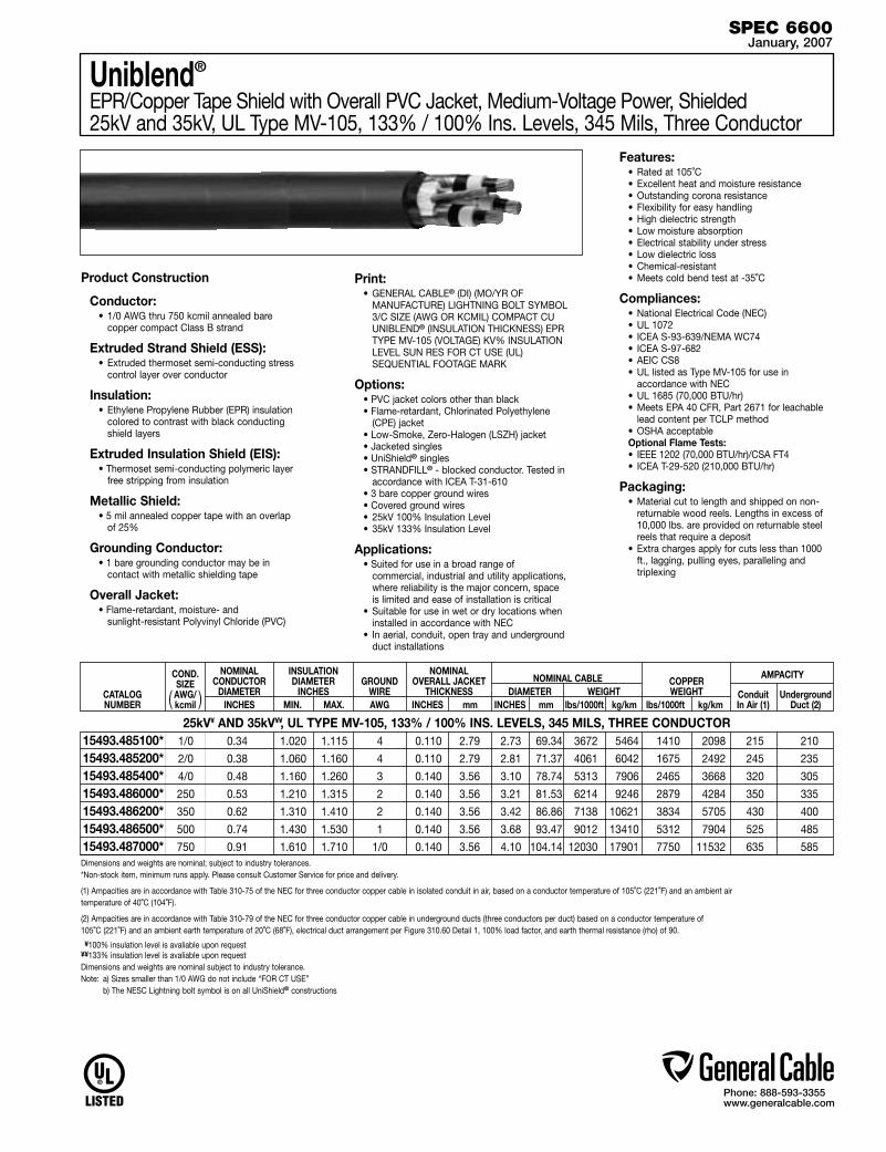
Phone: 888-593-3355www.generalcable.com
Product Construction
Conductor:• 1/0 AWG thru 750 kcmil annealed bare
copper compact Class B strand
Extruded Strand Shield (ESS):• Extruded thermoset semi-conducting stress
control layer over conductor
Insulation:• Ethylene Propylene Rubber (EPR) insulation
colored to contrast with black conducting shield layers
Extruded Insulation Shield (EIS):• Thermoset semi-conducting polymeric layer
free stripping from insulation
Metallic Shield:• 5 mil annealed copper tape with an overlap
of 25%
Grounding Conductor:• 1 bare grounding conductor may be in
contact with metallic shielding tape
Overall Jacket:• Flame-retardant, moisture- and
sunlight-resistant Polyvinyl Chloride (PVC)
Print:• GENERAL CABLE® (DI) (MO/YR OF
MANUFACTURE) LIGHTNING BOLT SYMBOL 3/C SIZE (AWG OR KCMIL) COMPACT CU UNIBLEND® (INSULATION THICKNESS) EPR TYPE MV-105 (VOLTAGE) KV% INSULATION LEVEL SUN RES FOR CT USE (UL) SEQUENTIAL FOOTAGE MARK
Options:• PVC jacket colors other than black • Flame-retardant, Chlorinated Polyethylene
(CPE) jacket• Low-Smoke, Zero-Halogen (LSZH) jacket• Jacketed singles• UniShield® singles• STRANDFILL® - blocked conductor. Tested in
accordance with ICEA T-31-610• 3 bare copper ground wires• Covered ground wires• 25kV 100% Insulation Level • 35kV 133% Insulation Level
Applications:• Suited for use in a broad range of
commercial, industrial and utility applications, where reliability is the major concern, space is limited and ease of installation is critical
• Suitable for use in wet or dry locations when installed in accordance with NEC
• In aerial, conduit, open tray and underground duct installations
Features:• Rated at 105˚C• Excellent heat and moisture resistance• Outstanding corona resistance• Flexibility for easy handling• High dielectric strength• Low moisture absorption• Electrical stability under stress• Low dielectric loss• Chemical-resistant• Meets cold bend test at -35˚C
Compliances:• National Electrical Code (NEC)• UL 1072• ICEA S-93-639/NEMA WC74 • ICEA S-97-682• AEIC CS8• UL listed as Type MV-105 for use in
accordance with NEC• UL 1685 (70,000 BTU/hr)• Meets EPA 40 CFR, Part 2671 for leachable
lead content per TCLP method• OSHA acceptableOptional Flame Tests:• IEEE 1202 (70,000 BTU/hr)/CSA FT4• ICEA T-29-520 (210,000 BTU/hr)
Packaging:• Material cut to length and shipped on non-
returnable wood reels. Lengths in excess of 10,000 lbs. are provided on returnable steel reels that require a deposit
• Extra charges apply for cuts less than 1000 ft., lagging, pulling eyes, paralleling and triplexing
Uniblend®
EPR/Copper Tape Shield with Overall PVC Jacket, Medium-Voltage Power, Shielded25kV and 35kV, UL Type MV-105, 133% / 100% Ins. Levels, 345 Mils, Three Conductor
SPEC 6600January, 2007
25kV¥ AND 35kV¥¥, UL TYPE MV-105, 133% / 100% INS. LEVELS, 345 MILS, THREE CONDUCTOR
CATALOG NUMBER
NOMINAL OVERALL JACKET
THICKNESS INCHES mm
COND. SIZE AWG/kcmil
NOMINAL CONDUCTOR
DIAMETERINCHES
INSULATION DIAMETER
INCHES MIN. MAX.
COPPER WEIGHT
lbs/1000ft kg/km
NOMINAL CABLE DIAMETER WEIGHTINCHES mm lbs/1000ft kg/km
AMPACITY
Conduit Underground In Air (1) Duct (2)
GROUND
WIREAWG( )
1/0 0.34 1.020 1.115 4 0.110 2.79 2.73 69.34 3672 5464 1410 2098 215 210
2/0 0.38 1.060 1.160 4 0.110 2.79 2.81 71.37 4061 6042 1675 2492 245 235
4/0 0.48 1.160 1.260 3 0.140 3.56 3.10 78.74 5313 7906 2465 3668 320 305
250 0.53 1.210 1.315 2 0.140 3.56 3.21 81.53 6214 9246 2879 4284 350 335
350 0.62 1.310 1.410 2 0.140 3.56 3.42 86.86 7138 10621 3834 5705 430 400
500 0.74 1.430 1.530 1 0.140 3.56 3.68 93.47 9012 13410 5312 7904 525 485
750 0.91 1.610 1.710 1/0 0.140 3.56 4.10 104.14 12030 17901 7750 11532 635 585
15493.485100*15493.485200*15493.485400*15493.486000*15493.486200*15493.486500*15493.487000*Dimensions and weights are nominal; subject to industry tolerances.*Non-stock item, minimum runs apply. Please consult Customer Service for price and delivery.
(1) Ampacities are in accordance with Table 310-75 of the NEC for three conductor copper cable in isolated conduit in air, based on a conductor temperature of 105˚C (221˚F) and an ambient air temperature of 40˚C (104˚F).
(2) Ampacities are in accordance with Table 310-79 of the NEC for three conductor copper cable in underground ducts (three conductors per duct) based on a conductor temperature of 105˚C (221˚F) and an ambient earth temperature of 20˚C (68˚F), electrical duct arrangement per Figure 310.60 Detail 1, 100% load factor, and earth thermal resistance (rho) of 90.
¥100% insulation level is avaliable upon request¥¥133% insulation level is avaliable upon request Dimensions and weights are nominal subject to industry tolerance. Note: a) Sizes smaller than 1/0 AWG do not include “FOR CT USE” b) The NESC Lightning bolt symbol is on all UniShield® constructions

Phone: 888-593-3355www.generalcable.com
Date of Issue 01/07Industrial Cables Section 7
600V – 35kV Industrial Armored Cables
SPECIFICATION # PRODUCT DESCRIPTION REVISION DATE
7050† Duralox® XLPE/AIA/PVC, Control, Armored Jan. 2007 600V, UL Type MC, Multi Conductor
7100† Duralox® XLPE/AIA/PVC, Power, Armored Jan. 2007 600V, UL Type MC, Three and Four Conductor (8 AWG—4/0 AWG)
7150† Duralox® XLPE/AIA/PVC, Power, Armored Jan. 2007 600V, UL Type MC, Three and Four Conductor (250 kcmil—1000 kcmil)
7160† Duralox® XLPE/AIA/PVC, Power, Armored, with Enhanced Ground Wires (50%) Jan. 2007 600V, UL Type MC, Three Conductor (1/0 AWG—1000 kcmil)
7200† Duralox® EPR/AIA/PVC, Power, Non-Shielded, Armored Jan. 2007 2400V, UL Type MV-90 or MC, Three Conductor
7250† Duralox® Uniblend® EPR/AIA/PVC, Power, Shielded, Armored Jan. 2007 5kV/8kV, UL Type MV-105 or MC, 133% / 100% Ins. Levels, 115 Mils, Three Conductor
7300† Duralox® Uniblend® EPR/AIA/PVC, Power, Shielded, Armored Jan. 2007 15kV, UL Type MV-105 or MC, 133% Ins. Level, 220 Mils, Three Conductor
7310 Duralox® Uniblend® EPR/AIA/PVC, Power, Shielded, Armored, with Enhanced Ground Wires (50%) Jan. 2007 15kV, UL Type MV-105 or MC, 133% Ins. Level, 220 Mils, Three Conductor
7350 Duralox® Uniblend® EPR/AIA/PVC, Power, Shielded, Armored Jan. 2007 25kV, UL Type MV-105 or MC, 100% Ins. Level, 260 Mils, Three Conductor
7400 Duralox® Uniblend® EPR/AIA/PVC, Power, Shielded, Armored Jan. 2007 35kV, UL Type MV-105 or MC, 100% Ins. Level, 345 Mils, Three Conductor
†Indicates these products are stocked by General Cable

Phone: 888-593-3355www.generalcable.com
Features:• Rated at 90˚C wet or dry• Sunlight-resistant• Provides excellent oil and chemical resistance• Excellent crush resistance • Provides a long service life• Flame-retardant and resistant to moisture• Cost-effective alternative to installations
in conduit• Meets cold bend test at - 25˚C
Compliances:• UL 1569• UL 44• ICEA S-95-658/NEMA WC 70• UL Type MC- 600 volts• NEC Type XHHW-2 conductors• IEEE 383 (70,000 BTU/hr)• UL 1581 (70,000 BTU/hr)• IEEE 1202 (70,000 BTU/hr)/CSA FT4• ICEA T-29-520 (210,000 BTU/hr)• Meets EPA 40 CFR part 261 for leachable lead
content per TCLP method• OSHA acceptable
Packaging:• Material cut to length and shipped on
non-returnable wood reels, while lengths in excess of 10,000 lbs. are provided on returnable steel reels that require a deposit. Extra charges apply for cuts less than 1000 ft., lagging, pulling eyes, paralleling and plexing
COPPER WEIGHT
lbs/1000ft kg/km
NET
WEIGHTlbs/1000ft kg/km
Duralox®
XLPE/AIA/PVC, Control, Armored 600V, UL Type MC, Multi Conductor
SPEC 7050January, 2007
CATALOG NUMBER
NO. OF
COND.
MIN. AVG. INSULATION
THICKNESS INCHES mm
NOM. DIA. (OVER) ARMOR
INCHES mm
GRND. WIRE SIZEAWG
2 14 0.030 0.76 14 0.49 12.5 0.050 1.27 0.60 15.3 39 58 175 261
3 14 0.030 0.76 14 0.52 13.2 0.050 1.27 0.63 16.0 52 78 183 273
4 14 0.030 0.76 14 0.55 14.0 0.050 1.27 0.66 16.8 65 97 233 347
5 14 0.030 0.76 14 0.59 15.0 0.050 1.27 0.69 17.6 79 118 246 367
7 14 0.030 0.76 14 0.64 16.3 0.050 1.27 0.74 18.8 104 155 297 443
9 14 0.030 0.76 14 0.72 18.3 0.050 1.27 0.83 21.1 130 193 379 564
12 14 0.030 0.76 14 0.80 20.3 0.050 1.27 0.90 22.9 168 250 460 685
19 14 0.030 0.76 14 0.99 25.2 0.050 1.27 1.02 25.9 259 385 621 924
25 14 0.030 0.76 14 1.07 27.2 0.050 1.27 1.17 29.7 337 502 776 1155
37 14 0.030 0.76 14 1.19 30.3 0.050 1.27 1.29 32.8 492 732 1043 1533
346410* 346420 346430* 346440 346450 346460* 346470* 346480* 346490* 346500*
14 AWG - MULTI CONDUCTOR - 600V
COND. SIZE
(AWG)
NOMINAL JACKET
THICKNESS INCHES mm
NOMINAL CABLE
O.D. INCHES mm
2 12 0.030 0.76 12 0.53 13.5 0.050 1.27 0.64 16.3 64 96 218 324
3 12 0.030 0.76 12 0.56 14.3 0.050 1.27 0.66 16.8 83 124 227 338
4 12 0.030 0.76 12 0.60 15.3 0.050 1.27 0.71 18.1 103 154 272 405
5 12 0.030 0.76 12 0.64 16.3 0.050 1.27 0.75 19.1 129 192 336 500
7 12 0.030 0.76 12 0.70 17.8 0.050 1.27 0.81 20.6 165 246 380 566
9 12 0.030 0.76 12 0.78 19.8 0.050 1.27 0.89 22.6 214 319 479 713
12 12 0.030 0.76 12 0.86 21.9 0.050 1.27 0.97 24.7 279 416 596 887
19 12 0.030 0.76 12 0.99 25.2 0.050 1.27 1.10 28.0 428 637 830 1235
25 12 0.030 0.76 12 1.18 30.0 0.050 1.27 1.28 32.5 557 829 1058 1575
37 12 0.030 0.76 12 1.31 33.3 0.050 1.27 1.41 35.8 793 1180 1403 2088
346510* 346520 346530 346540 346550 346560* 346570* 346580* 346590* 346600*
12 AWG - MULTI CONDUCTOR - 600V
3 10 0.030 0.76 10 0.61 15.5 0.050 1.27 0.72 18.3 131 195 301 448
4 10 0.030 0.76 10 0.66 16.8 0.050 1.27 0.77 19.6 164 244 355 529
346610 346620
10 AWG - MULTI CONDUCTOR - 600V
Product Construction
Conductors:• 14 AWG thru 10 AWG tinned, compressed
copper• Class B stranding per ASTM B3 and B8
Insulation:• Flame-retardant Cross-Linked Polyethylene
(XLPE)• Color-coded: per ICEA Method 1; Table E-2 (does not include white or green)
Ground:• Annealed bare copper Class B stranding per
ASTM B8
Armor:• Aluminum Interlocked Armor (AIA)
Jacket:• Flame-retardant, moisture- and sunlight-resistant
Polyvinyl Chloride (PVC)—Black
Print:• GENERAL CABLE® XX/C XX AWG (UL) TYPE
MC XHHW-2 CDRS DIR BUR SUN RES FOR CT USE 600V MONTH-YEAR SEQUENTIAL PRINT
Options:• Tinned copper conductors • E-1 color code• Copper tape shield or aluminum/polymer tape
shield with tinned copper drain wire over cable core
• Inner jacket only, outer jacket only, or both • Galvanized Steel Interlocked Armor (GSIA)• Other constructions available upon request
Applications:• In all raceways or direct burial• In wet or dry locations• Permitted for use in Class I Division 2, Class
II Division 2, and Class III Division 1 and 2 per NEC Article 334
Dimensions and weights are nominal; subject to industry tolerances.*Non-stock item, minimum runs apply. Please consult Customer Service for price and delivery.
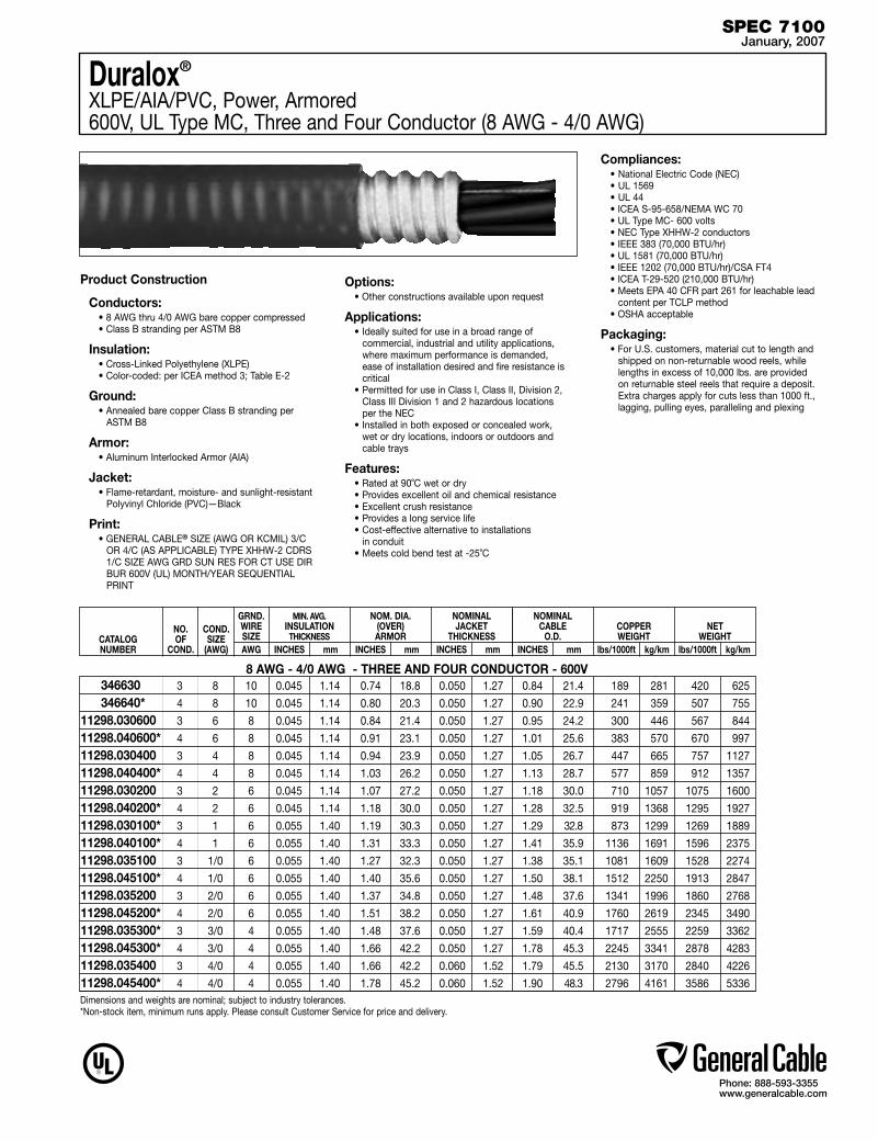
Phone: 888-593-3355www.generalcable.com
Duralox®
XLPE/AIA/PVC, Power, Armored 600V, UL Type MC, Three and Four Conductor (8 AWG - 4/0 AWG)
Product Construction
Conductors:• 8 AWG thru 4/0 AWG bare copper compressed • Class B stranding per ASTM B8
Insulation:• Cross-Linked Polyethylene (XLPE)• Color-coded: per ICEA method 3; Table E-2
Ground:• Annealed bare copper Class B stranding per
ASTM B8
Armor:• Aluminum Interlocked Armor (AIA)
Jacket:• Flame-retardant, moisture- and sunlight-resistant
Polyvinyl Chloride (PVC)—Black
Print:• GENERAL CABLE® SIZE (AWG OR KCMIL) 3/C
OR 4/C (AS APPLICABLE) TYPE XHHW-2 CDRS 1/C SIZE AWG GRD SUN RES FOR CT USE DIR BUR 600V (UL) MONTH/YEAR SEQUENTIAL PRINT
Options:• Other constructions available upon request
Applications:• Ideally suited for use in a broad range of
commercial, industrial and utility applications, where maximum performance is demanded, ease of installation desired and fire resistance is critical
• Permitted for use in Class I, Class II, Division 2, Class III Division 1 and 2 hazardous locations per the NEC
• Installed in both exposed or concealed work, wet or dry locations, indoors or outdoors and cable trays
Features:• Rated at 90˚C wet or dry• Provides excellent oil and chemical resistance• Excellent crush resistance• Provides a long service life• Cost-effective alternative to installations
in conduit• Meets cold bend test at -25˚C
Compliances:• National Electric Code (NEC)• UL 1569• UL 44 • ICEA S-95-658/NEMA WC 70• UL Type MC- 600 volts• NEC Type XHHW-2 conductors• IEEE 383 (70,000 BTU/hr)• UL 1581 (70,000 BTU/hr)• IEEE 1202 (70,000 BTU/hr)/CSA FT4• ICEA T-29-520 (210,000 BTU/hr)• Meets EPA 40 CFR part 261 for leachable lead
content per TCLP method• OSHA acceptable
Packaging:• For U.S. customers, material cut to length and
shipped on non-returnable wood reels, while lengths in excess of 10,000 lbs. are provided on returnable steel reels that require a deposit. Extra charges apply for cuts less than 1000 ft., lagging, pulling eyes, paralleling and plexing
SPEC 7100January, 2007
CATALOG NUMBER
NO. OF
COND.
MIN. AVG. INSULATION
THICKNESS INCHES mm
NOM. DIA. (OVER) ARMOR
INCHES mm
GRND. WIRE SIZEAWG
3 8 10 0.045 1.14 0.74 18.8 0.050 1.27 0.84 21.4 189 281 420 625
4 8 10 0.045 1.14 0.80 20.3 0.050 1.27 0.90 22.9 241 359 507 755
3 6 8 0.045 1.14 0.84 21.4 0.050 1.27 0.95 24.2 300 446 567 844
4 6 8 0.045 1.14 0.91 23.1 0.050 1.27 1.01 25.6 383 570 670 997
3 4 8 0.045 1.14 0.94 23.9 0.050 1.27 1.05 26.7 447 665 757 1127
4 4 8 0.045 1.14 1.03 26.2 0.050 1.27 1.13 28.7 577 859 912 1357
3 2 6 0.045 1.14 1.07 27.2 0.050 1.27 1.18 30.0 710 1057 1075 1600
4 2 6 0.045 1.14 1.18 30.0 0.050 1.27 1.28 32.5 919 1368 1295 1927
3 1 6 0.055 1.40 1.19 30.3 0.050 1.27 1.29 32.8 873 1299 1269 1889
4 1 6 0.055 1.40 1.31 33.3 0.050 1.27 1.41 35.9 1136 1691 1596 2375
3 1/0 6 0.055 1.40 1.27 32.3 0.050 1.27 1.38 35.1 1081 1609 1528 2274
4 1/0 6 0.055 1.40 1.40 35.6 0.050 1.27 1.50 38.1 1512 2250 1913 2847
3 2/0 6 0.055 1.40 1.37 34.8 0.050 1.27 1.48 37.6 1341 1996 1860 2768
4 2/0 6 0.055 1.40 1.51 38.2 0.050 1.27 1.61 40.9 1760 2619 2345 3490
3 3/0 4 0.055 1.40 1.48 37.6 0.050 1.27 1.59 40.4 1717 2555 2259 3362
4 3/0 4 0.055 1.40 1.66 42.2 0.050 1.27 1.78 45.3 2245 3341 2878 4283
3 4/0 4 0.055 1.40 1.66 42.2 0.060 1.52 1.79 45.5 2130 3170 2840 4226
4 4/0 4 0.055 1.40 1.78 45.2 0.060 1.52 1.90 48.3 2796 4161 3586 5336
346630 346640*11298.03060011298.040600*11298.03040011298.040400*11298.03020011298.040200*11298.030100*11298.040100*11298.03510011298.045100*11298.03520011298.045200*11298.035300*11298.045300*11298.03540011298.045400*
8 AWG - 4/0 AWG - THREE AND FOUR CONDUCTOR - 600V
COND. SIZE
(AWG)
NOMINAL JACKET
THICKNESS INCHES mm
NOMINAL CABLE
O.D. INCHES mm
COPPER WEIGHT
lbs/1000ft kg/km
NET
WEIGHT lbs/1000ft kg/km
Dimensions and weights are nominal; subject to industry tolerances.*Non-stock item, minimum runs apply. Please consult Customer Service for price and delivery.
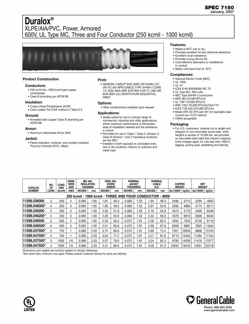
Phone: 888-593-3355www.generalcable.com
Duralox®
XLPE/AIA/PVC, Power, Armored 600V, UL Type MC, Three and Four Conductor (250 kcmil - 1000 kcmil)
Product Construction
Conductors:• 250 kcmil thru 1000 kcmil bare copper
compressed • Class B stranding per ASTM B8
Insulation:• Cross-Linked Polyethylene (XLPE)• Color-coded: Per ICEA method 3; Table E-2
Ground:• Annealed bare copper Class B stranding per
ASTM B8
Armor:• Aluminum Interlocked Armor (AIA)
Jacket:• Flame-retardant, moisture- and sunlight-resistant
Polyvinyl Chloride (PVC)—Black
Print:• GENERAL CABLE® SIZE (AWG OR KCMIL) 3/C
OR 4/C (AS APPLICABLE) TYPE XHHW-2 CDRS 1/C SIZE AWG GRD SUN RES FOR CT USE DIR BUR 600V (UL) MONTH/YEAR SEQUENTIAL PRINT
Options:• Other constructions available upon request
Applications:• Ideally suited for use in a broad range of
commercial, industrial and utility applications, where maximum performance is demanded, ease of installation desired and fire resistance is critical
• Permitted for use in Class I, Class II, Division 2, Class III Division 1 and 2 hazardous locations per the NEC
• Installed in both exposed or concealed work, wet or dry locations, indoors or outdoors and cable trays
Features:• Rated at 90˚C wet or dry• Provides excellent oil and chemical resistance• Excellent crush resistance• Provides a long service life• Cost-effective alternative to installations
in conduit• Meets cold bend test at -25˚C
Compliances:• National Electric Code (NEC)• UL 1569• UL 44 • ICEA S-95-658/NEMA WC 70• UL Type MC- 600 volts• NEC Type XHHW-2 conductors• IEEE 383 (70,000 BTU/hr)• UL 1581 (70,000 BTU/hr)• IEEE 1202 (70,000 BTU/hr)/CSA FT4• ICEA T-29-520 (210,000 BTU/hr)• Meets EPA 40 CFR part 261 for leachable lead
content per TCLP method• OSHA acceptable
Packaging:• For U.S. customers, material cut to length and
shipped on non-returnable wood reels, while lengths in excess of 10,000 lbs. are provided on returnable steel reels that require a deposit. Extra charges apply for cuts less than 1000 ft., lagging, pulling eyes, paralleling and plexing
SPEC 7150January, 2007
CATALOG NUMBER
NO. OF
COND.
MIN. AVG. INSULATION
THICKNESS INCHES mm
NOM. DIA. (OVER) ARMOR
INCHES mm
GRND. WIRE SIZEAWG
3 250 4 0.065 1.65 1.81 46.0 0.060 1.52 1.94 49.3 2495 3713 3295 4903
4 250 4 0.065 1.65 1.95 49.5 0.060 1.52 2.07 52.6 3282 4884 4174 6211
3 350 3 0.065 1.65 2.03 51.6 0.060 1.52 2.16 54.9 3474 5170 4400 6548
4 350 3 0.065 1.65 2.20 55.9 0.060 1.52 2.32 59.0 4576 6810 5608 8345
3 500 2 0.065 1.65 2.30 58.5 0.075 1.91 2.46 62.5 4934 7343 6126 9116
4 500 2 0.065 1.65 2.51 63.8 0.075 1.91 2.66 67.6 6509 9687 7825 11644
3 750 1 0.080 2.03 2.74 69.6 0.075 1.91 2.89 73.4 7351 10940 8806 13104
4 750 1 0.080 2.03 3.04 77.2 0.075 1.91 3.21 81.6 9713 14455 11494 17104
3 1000 1/0 0.080 2.03 3.07 78.0 0.075 1.91 3.24 82.3 9783 14559 11476 17077
4 1000 1/0 0.080 2.03 3.41 86.6 0.075 1.91 3.58 91.0 12932 19245 14931 22218
11298.036000 11298.046000* 11298.036200 11298.046200* 11298.036500 11298.046500*11298.037000* 11298.047000* 11298.037500* 11298.047500*
250 kcmil - 1000 kcmil - THREE AND FOUR CONDUCTOR - 600V
COND. SIZE
(kcmil)
NOMINAL JACKET
THICKNESS INCHES mm
NOMINAL CABLE
O.D. INCHES mm
COPPER WEIGHT
lbs/1000ft kg/km
NET
WEIGHT lbs/1000ft kg/km
Dimensions and weights are nominal; subject to industry tolerances.*Non-stock item, minimum runs apply. Please consult Customer Service for price and delivery.

Phone: 888-593-3355www.generalcable.com
Duralox®
XLPE/AIA/PVC, Power, Armored, with Enhanced Ground Wires (50%) 600V, UL Type MC, Three Conductor (1/0 AWG—1000 kcmil)
Product Construction
Conductors:• 1/0 AWG thru 1000 kcmil bare copper
compressed • Class B stranding per ASTM B8
Insulation:• Cross-Linked Polyethylene (XLPE)• Color-coded: Per ICEA method 3; Table E-2
Ground:• Annealed bare copper Class B stranding per
ASTM B8
Armor:• Aluminum Interlocked Armor (AIA)
Jacket:• Flame-retardant, moisture- and sunlight-resistant
Polyvinyl Chloride (PVC)—Black
Print:• GENERAL CABLE® SIZE (AWG OR KCMIL) 3/C
TYPE XHHW-2 CDRS 1/C SIZE AWG GRD SUN RES FOR CT USE DIR BUR 600V (UL) MONTH/YEAR SEQUENTIAL PRINT
Options:• Other constructions available upon request
Applications:• Ideally suited for use in a broad range of
commercial, industrial and utility applications, where maximum performance is demanded, ease of installation desired and fire resistance is critical
• Permitted for use in Class I, Class II, Division 2, Class III Division 1 and 2 hazardous locations per the NEC
• Installed in both exposed or concealed work, wet or dry locations, indoors or outdoors and cable trays
Features:• Rated at 90˚C wet or dry• Provides excellent oil and chemical resistance• Excellent crush resistance• Provides a long service life• Cost-effective alternative to installations
in conduit• Meets cold bend test at -25˚C
Compliances:• National Electric Code (NEC)• UL 1569• UL 44 • ICEA S-95-658/NEMA WC 70• UL Type MC- 600 volts• NEC Type XHHW-2 conductors• IEEE 383 (70,000 BTU/hr)• UL 1581 (70,000 BTU/hr)• IEEE 1202 (70,000 BTU/hr)/CSA FT4• ICEA T-29-520 (210,000 BTU/hr)• Meets EPA 40 CFR part 261 for leachable lead
content per TCLP method• OSHA acceptable
Packaging:• For U.S. customers, material cut to length and
shipped on non-returnable wood reels, while lengths in excess of 10,000 lbs. are provided on returnable steel reels that require a deposit. Extra charges apply for cuts less than 1000 ft., lagging, pulling eyes, paralleling and plexing
SPEC 7160January, 2007
CATALOG NUMBER
NO. OF
COND.
MIN. AVG. INSULATION
THICKNESS INCHES mm
NOM. DIA. (OVER) ARMOR
INCHES mm
GRND. WIRE SIZEAWG
3 1/0 3x6 0.055 1.40 1.27 32.3 0.050 1.27 1.38 35.1 1247 1858 1694 2524
3 2/0 3x6 0.055 1.40 1.37 34.8 0.050 1.27 1.48 37.6 1507 2245 2026 3019
3 3/0 3x5 0.055 1.40 1.48 37.6 0.050 1.27 1.59 40.4 1939 2889 2481 3697
3 4/0 3x4 0.055 1.40 1.66 42.2 0.060 1.52 1.79 45.5 2395 3569 3105 4626
3 250 3x4 0.065 1.65 1.81 46.0 0.060 1.52 1.94 49.3 2760 4112 3560 5304
3 350 3x2 0.065 1.65 2.03 51.6 0.060 1.52 2.16 54.9 3944 5877 4870 7256
3 500 3x1 0.065 1.65 2.30 58.5 0.075 1.91 2.46 62.5 5473 8155 6665 9931
3 750 3x2/0 0.080 2.03 2.74 69.6 0.075 1.91 2.89 73.4 8022 11953 9477 14121
3 1000 3x3/0 0.080 2.03 3.07 78.0 0.075 1.91 3.24 82.3 10629 15837 12322 18360
11298.515100* 11298.515200* 11298.515300* 11298.515400* 11298.516000*11298.516200*11298.516500 11298.517000* 11298.517500*
1/0 AWG - 1000 kcmil - THREE CONDUCTOR - 600V
COND. SIZE AWG/ kcmil
NOMINAL JACKET
THICKNESS INCHES mm
NOMINAL CABLE
O.D. INCHES mm
COPPER WEIGHT
lbs/1000ft kg/km
NET
WEIGHT lbs/1000ft kg/km( )
Dimensions and weights are nominal; subject to industry tolerances.*Non-stock item, minimum runs apply. Please consult Customer Service for price and delivery.
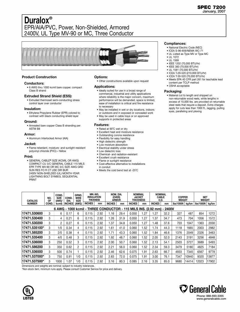
Phone: 888-593-3355www.generalcable.com
Duralox®
EPR/AIA/PVC, Power, Non-Shielded, Armored 2400V, UL Type MV-90 or MC, Three Conductor
Product Construction
Conductors:• 6 AWG thru 1000 kcmil bare copper, compact
Class B strand
Extruded Strand Shield (ESS):• Extruded thermoset semi-conducting stress
control layer over conductor
Insulation:• Ethylene Propylene Rubber (EPR) colored to
contrast with black conducting shield layer
Ground:• Annealed bare copper Class B stranding per
ASTM B8
Armor:• Aluminum Interlocked Armor (AIA)
Jacket:• Flame-retardant, moisture- and sunlight-resistant
polyvinyl chloride (PVC)—Yellow
Print:• GENERAL CABLE® SIZE (KCMIL OR AWG)
COMPACT CU 3/C GENERAL CABLE 115 MILS EPR TYPE MV-90 OR MC 3/C SIZE AWG GRD SUN RES FO R CT USE DIR BUR 2400V NON-SHIELDED (UL) MONTH-YEAR LIGHTNING BOLT SYMBOL SEQUENTIAL PRINT
Options:• Other constructions available upon request
Applications:• Ideally suited for use in a broad range of
commercial, industrial and utility applications where reliability is the major concern, maximum performance will be demanded, space is limited, ease of installation is critical and fire resistance is necessary
• May be installed in wet or dry locations, indoors or outdoors and in exposed or concealed work
• May be used in cable trays or on approved supports in protected areas
Features:• Rated at 90˚C wet or dry• Excellent heat and moisture resistance• Outstanding corona resistance• Flexibility for easy handling• High dielectric strength• Low moisture absorption• Electrical stability under stress• Low dielectric loss• Chemical- and radiation-resistant• Excellent crush resistance• Flame or sunlight resistance• Cost-effective alternative to installations
in conduit• Meets the cold bend test at -25˚C
Compliances:• National Electric Code (NEC)• ICEA S-96-659/NEMA WC-71 • UL Listed as Type MV or Type MC• UL 1072• UL 1569• IEEE 1202 (70,000 BTU/hr)• IEEE 383 (70,000 BTU/hr)• UL 1581 (70,000 BTU/hr)• ICEA T-29-520 (210,000 BTU/hr)• ICEA T-30-520 (70,000 BTU/hr)• Meets EPA 40 CFR part 261 for leachable lead
content per TCLP method• OSHA acceptable
Packaging:• Material cut to length and shipped on
non-returnable wood reels, while lengths in excess of 10,000 lbs. are provided on returnable steel reels that require a deposit. Extra charges apply for cuts less than 1000 ft., lagging, pulling eyes, paralleling and plexing
SPEC 7200January, 2007
CATALOG NUMBER
NO. OF
COND.
MIN. AVG. INSULATION
THICKNESS INCHES mm
NOM. DIA. (OVER) ARMOR
INCHES mm
GRND. WIRE SIZE
(AWG)
3 6 0.17 6 0.115 2.92 1.16 29.4 0.050 1.27 1.27 32.2 327 487 854 1272
3 4 0.21 6 0.115 2.92 1.26 31.9 0.050 1.27 1.37 34.7 473 704 1056 1572
3 2 0.27 6 0.115 2.92 1.37 34.8 0.050 1.27 1.48 37.6 703 1047 1363 2030
3 1/0 0.34 4 0.115 2.92 1.61 41.0 0.060 1.52 1.74 44.3 1118 1665 2003 2982
3 2/0 0.38 4 0.115 2.92 1.71 43.3 0.060 1.52 1.84 46.6 1376 2049 2326 3463
3 4/0 0.48 3 0.115 2.92 1.92 48.7 0.060 1.52 2.05 52.0 2143 3191 3256 4848
3 250 0.52 3 0.115 2.92 2.00 50.7 0.060 1.52 2.13 54.1 2503 3727 3689 5493
3 350 0.62 2 0.115 2.92 2.21 56.0 0.060 1.52 2.34 59.3 3479 5180 4825 7184
3 500 0.74 1 0.115 2.92 2.46 62.6 0.075 1.91 2.63 66.7 4933 7345 6567 9778
3 750 0.91 1/0 0.115 2.92 2.83 72.0 0.075 1.91 3.00 76.1 7347 10940 9320 13877
3 1000 1.07 1/0 0.115 2.92 3.16 80.3 0.085 2.16 3.35 85.0 9680 14414 12023 17902
17471.53060017471.53040017471.53020017471.535100*17471.58520017471.53540017471.53600017471.58620017471.53650017471.537000*17471.537500*
6 AWG - 1000 kcmil - THREE CONDUCTOR - 115 MILS INS. (2.92 mm) - 2400V
COND.SIZE
(AWG/kcmil)
NOMINAL JACKET
THICKNESS INCHES mm
NOMINAL CABLE
O.D. INCHES mm
COPPER WEIGHT
lbs/1000ft kg/km
NET
WEIGHT lbs/1000ft kg/km
COND. DIA.
INCHES
Dimensions and weights are nominal; subject to industry tolerances.*Non-stock item, minimum runs apply. Please consult Customer Service for price and delivery.
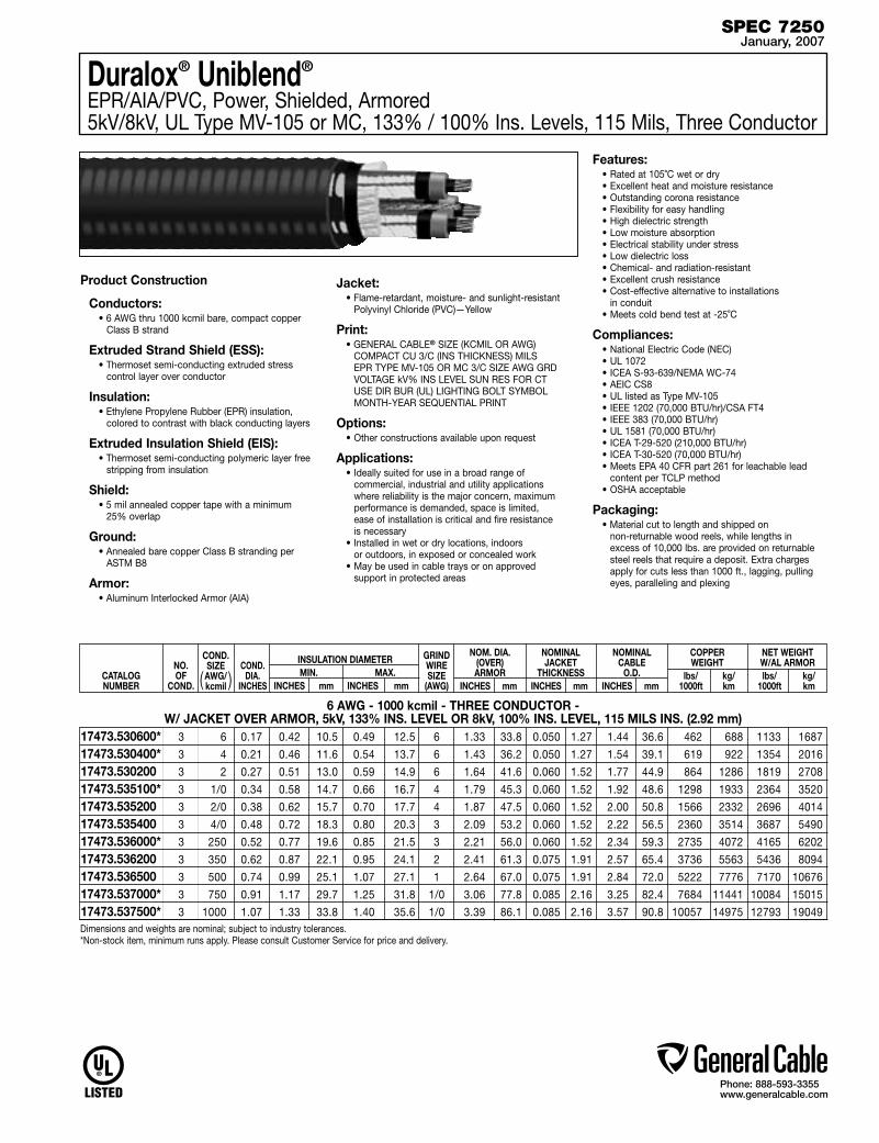
Phone: 888-593-3355www.generalcable.com
CATALOG NUMBER
NO. OF
COND.
3 6 0.17 0.42 10.5 0.49 12.5 6 1.33 33.8 0.050 1.27 1.44 36.6 462 688 1133 1687
3 4 0.21 0.46 11.6 0.54 13.7 6 1.43 36.2 0.050 1.27 1.54 39.1 619 922 1354 2016
3 2 0.27 0.51 13.0 0.59 14.9 6 1.64 41.6 0.060 1.52 1.77 44.9 864 1286 1819 2708
3 1/0 0.34 0.58 14.7 0.66 16.7 4 1.79 45.3 0.060 1.52 1.92 48.6 1298 1933 2364 3520
3 2/0 0.38 0.62 15.7 0.70 17.7 4 1.87 47.5 0.060 1.52 2.00 50.8 1566 2332 2696 4014
3 4/0 0.48 0.72 18.3 0.80 20.3 3 2.09 53.2 0.060 1.52 2.22 56.5 2360 3514 3687 5490
3 250 0.52 0.77 19.6 0.85 21.5 3 2.21 56.0 0.060 1.52 2.34 59.3 2735 4072 4165 6202
3 350 0.62 0.87 22.1 0.95 24.1 2 2.41 61.3 0.075 1.91 2.57 65.4 3736 5563 5436 8094
3 500 0.74 0.99 25.1 1.07 27.1 1 2.64 67.0 0.075 1.91 2.84 72.0 5222 7776 7170 10676
3 750 0.91 1.17 29.7 1.25 31.8 1/0 3.06 77.8 0.085 2.16 3.25 82.4 7684 11441 10084 15015
3 1000 1.07 1.33 33.8 1.40 35.6 1/0 3.39 86.1 0.085 2.16 3.57 90.8 10057 14975 12793 19049
17473.530600* 17473.530400* 17473.530200 17473.535100* 17473.535200 17473.535400 17473.536000* 17473.536200 17473.536500 17473.537000* 17473.537500*
6 AWG - 1000 kcmil - THREE CONDUCTOR - W/ JACKET OVER ARMOR, 5kV, 133% INS. LEVEL OR 8kV, 100% INS. LEVEL, 115 MILS INS. (2.92 mm)
COND. SIZE AWG/ kcmil
NOMINAL CABLE
O.D. INCHES mm
NET WEIGHT W/AL ARMOR
lbs/ kg/ 1000ft km
COND.
DIA. INCHES
INSULATION DIAMETER MIN. MAX. INCHES mm INCHES mm
COPPER WEIGHT
lbs/ kg/ 1000ft km
NOMINAL JACKET
THICKNESS INCHES mm
NOM. DIA. (OVER) ARMOR
INCHES mm
GRIND WIRE SIZE
(AWG)( )
Duralox® Uniblend®
EPR/AIA/PVC, Power, Shielded, Armored 5kV/8kV, UL Type MV-105 or MC, 133% / 100% Ins. Levels, 115 Mils, Three Conductor
Product Construction
Conductors:• 6 AWG thru 1000 kcmil bare, compact copper
Class B strand
Extruded Strand Shield (ESS):• Thermoset semi-conducting extruded stress
control layer over conductor
Insulation:• Ethylene Propylene Rubber (EPR) insulation,
colored to contrast with black conducting layers
Extruded Insulation Shield (EIS):• Thermoset semi-conducting polymeric layer free
stripping from insulation
Shield:• 5 mil annealed copper tape with a minimum
25% overlap
Ground:• Annealed bare copper Class B stranding per
ASTM B8
Armor:• Aluminum Interlocked Armor (AIA)
Jacket:• Flame-retardant, moisture- and sunlight-resistant
Polyvinyl Chloride (PVC)—Yellow
Print: • GENERAL CABLE® SIZE (KCMIL OR AWG)
COMPACT CU 3/C (INS THICKNESS) MILS EPR TYPE MV-105 OR MC 3/C SIZE AWG GRD VOLTAGE kV% INS LEVEL SUN RES FOR CT USE DIR BUR (UL) LIGHTING BOLT SYMBOL MONTH-YEAR SEQUENTIAL PRINT
Options:• Other constructions available upon request
Applications:• Ideally suited for use in a broad range of
commercial, industrial and utility applications where reliability is the major concern, maximum performance is demanded, space is limited, ease of installation is critical and fire resistance is necessary
• Installed in wet or dry locations, indoors or outdoors, in exposed or concealed work
• May be used in cable trays or on approved support in protected areas
Features:• Rated at 105˚C wet or dry• Excellent heat and moisture resistance• Outstanding corona resistance• Flexibility for easy handling• High dielectric strength• Low moisture absorption• Electrical stability under stress• Low dielectric loss• Chemical- and radiation-resistant• Excellent crush resistance• Cost-effective alternative to installations
in conduit• Meets cold bend test at -25˚C
Compliances:• National Electric Code (NEC)• UL 1072• ICEA S-93-639/NEMA WC-74• AEIC CS8• UL listed as Type MV-105• IEEE 1202 (70,000 BTU/hr)/CSA FT4• IEEE 383 (70,000 BTU/hr)• UL 1581 (70,000 BTU/hr)• ICEA T-29-520 (210,000 BTU/hr)• ICEA T-30-520 (70,000 BTU/hr)• Meets EPA 40 CFR part 261 for leachable lead
content per TCLP method• OSHA acceptable
Packaging:• Material cut to length and shipped on
non-returnable wood reels, while lengths in excess of 10,000 lbs. are provided on returnable steel reels that require a deposit. Extra charges apply for cuts less than 1000 ft., lagging, pulling eyes, paralleling and plexing
SPEC 7250January, 2007
Dimensions and weights are nominal; subject to industry tolerances.*Non-stock item, minimum runs apply. Please consult Customer Service for price and delivery.

Phone: 888-593-3355www.generalcable.com
Duralox® Uniblend®
EPR/AIA/PVC, Power, Shielded, Armored 15kV, UL Type MV-105 or MC, 133% Ins. Level, 220 Mils, Three Conductor
Product Construction
Conductors:• 2 AWG thru 1000 kcmil bare, compact copper
Class B strand
Extruded Strand Shield (ESS):• Thermoset semi-conducting extruded stress
control layer over conductor
Insulation:• Ethylene Propylene Rubber (EPR) insulation,
colored to contrast with black conducting layers
Extruded Insulation Shield (EIS):• Thermoset semi-conducting polymeric layer free
stripping from insulation
Shield:• 5 mil annealed copper tape with a minimum
25% overlap
Ground:• Annealed bare copper Class B stranding per
ASTM B8
Armor:• Aluminum Interlocked Armor (AIA)
Jacket:• Flame-retardant, moisture- and sunlight-resistant
Polyvinyl Chloride (PVC)—Red
Print: • GENERAL CABLE® SIZE (KCMIL OR AWG)
COMPACT CU 3/C (INS THICKNESS) MILS EPR TYPE MV-105 OR MC 3/C SIZE AWG GRD VOLTAGE kV% INS LEVEL SUN RES FOR CT USE DIR BUR (UL) LIGHTING BOLT SYMBOL MONTH-YEAR SEQUENTIAL PRINT
Options:• Other constructions available upon request
Applications:• Ideally suited for use in a broad range of
commercial, industrial and utility applications where reliability is the major concern, maximum performance is demanded, space is limited, ease of installation is critical and fire resistance is necessary
• Installed in wet or dry locations, indoors or outdoors, in exposed or concealed work
• May be used in cable trays or on approved support in protected areas
Features:• Rated at 105˚C wet or dry• Excellent heat and moisture resistance• Outstanding corona resistance• Flexibility for easy handling• High dielectric strength• Low moisture absorption
Features (con’t):• Electrical stability under stress• Low dielectric loss• Chemical- and radiation-resistant• Excellent crush resistance• Cost-effective alternative to installations
in conduit• Meets cold bend test at -25˚C
Compliances:• National Electric Code (NEC)• UL 1072• ICEA S-93-639/NEMA WC-74• AEIC CS8• UL listed as Type MV-105• IEEE 1202 (70,000 BTU/hr)/CSA FT4• IEEE 383 (70,000 BTU/hr)• UL 1581 (70,000 BTU/hr)• ICEA T-29-520 (210,000 BTU/hr)• ICEA T-30-520 (70,000 BTU/hr)• Meets EPA 40 CFR part 261 for leachable lead
content per TCLP method• OSHA acceptable
Packaging:• Material cut to length and shipped on
non-returnable wood reels, while lengths in excess of 10,000 lbs. are provided on returnable steel reels that require a deposit. Extra charges apply for cuts less than 1000 ft., lagging, pulling eyes, paralleling and plexing
SPEC 7300January, 2007
CATALOG NUMBER
NO. OF
COND.
COND. SIZE AWG/ kcmil
NOMINAL CABLE
O.D. INCHES mm
NET WEIGHT W/AL ARMOR
lbs/ kg/ 1000ft km
COND.
DIA. INCHES
INSULATION DIAMETER MIN. MAX. INCHES mm INCHES mm
COPPER WEIGHT
lbs/ kg/ 1000ft km
NOMINAL JACKET
THICKNESS INCHES mm
NOM. DIA. (OVER) ARMOR
INCHES mm
GRIND WIRE SIZE
(AWG)( )
3 2 0.27 0.71 18.0 0.80 20.3 6 2.08 52.8 0.060 1.52 2.21 56.1 919 1368 2416 3597
3 1/0 0.34 0.78 19.8 0.87 22.0 4 2.22 56.5 0.060 1.52 2.35 59.8 1352 2013 2997 4463
3 2/0 0.38 0.82 20.8 0.91 24.3 4 2.31 58.7 0.060 1.52 2.44 62.0 1620 2412 3371 5019
3 4/0 0.48 0.92 23.4 1.01 25.6 3 2.53 64.3 0.075 1.91 2.70 68.5 2414 3594 4502 6703
3 250 0.53 0.97 24.6 1.06 26.9 3 2.65 67.2 0.075 1.91 2.81 71.3 2789 4153 5005 7452
3 350 0.62 1.07 27.2 1.16 29.4 2 2.85 72.4 0.075 1.91 3.01 76.6 3790 5643 6252 9309
3 500 0.74 1.19 30.2 1.28 32.4 1 3.11 79.0 0.085 2.16 3.30 83.7 5276 7856 8091 12047
3 750 0.91 1.37 34.8 1.46 37.1 1/0 3.50 89.0 0.085 2.16 3.69 93.6 7738 11522 11086 16507
3 1000 1.06 1.52 38.6 1.61 40.9 1/0 3.83 97.3 0.085 2.16 4.01 101.9 10111 15055 13870 20652
17476.530200 17476.535100* 17476.535200 17476.535400 17476.536000* 17476.536200 17476.536500 17476.537000* 17476.537500*
2 AWG - 1000 kcmil - THREE CONDUCTOR - W/ JACKET OVER ARMOR, 15kV, 133% INS. LEVEL, 220 MILS INS. (5.59 mm)
Dimensions and weights are nominal; subject to industry tolerances.*Non-stock item, minimum runs apply. Please consult Customer Service for price and delivery.

Phone: 888-593-3355www.generalcable.com
Duralox® Uniblend®
EPR/AIA/PVC, Power, Shielded, Armored, with Enhanced Ground Wires (50%) 15kV, UL Type MV-105 or MC, 133% Ins. Level, 220 Mils, Three Conductor
Product Construction
Conductors:• 1/0 AWG thru 1000 kcmil bare, compact copper
Class B strand
Extruded Strand Shield (ESS):• Thermoset semi-conducting extruded stress
control layer over conductor
Insulation:• Ethylene Propylene Rubber (EPR) insulation,
colored to contrast with black conducting layers
Extruded Insulation Shield (EIS):• Thermoset semi-conducting polymeric layer free
stripping from insulation
Shield:• 5 mil annealed copper tape with a minimum
25% overlap
Ground:• Annealed bare copper Class B stranding per
ASTM B8
Armor:• Aluminum Interlocked Armor (AIA)
Jacket:• Flame-retardant, moisture- and sunlight-resistant
Polyvinyl Chloride (PVC)—Red
Print: • GENERAL CABLE® SIZE (KCMIL OR AWG)
COMPACT CU 3/C (INS THICKNESS) MILS EPR TYPE MV-105 OR MC 3/C SIZE AWG GRD VOLTAGE kV% INS LEVEL SUN RES FOR CT USE DIR BUR (UL) LIGHTING BOLT SYMBOL MONTH-YEAR SEQUENTIAL PRINT
Options:• Other constructions available upon request
Applications:• Ideally suited for use in a broad range of
commercial, industrial and utility applications where reliability is the major concern, maximum performance is demanded, space is limited, ease of installation is critical and fire resistance is necessary
• Installed in wet or dry locations, indoors or outdoors, in exposed or concealed work
• May be used in cable trays or on approved support in protected areas
Features:• Rated at 105˚C wet or dry• Excellent heat and moisture resistance• Outstanding corona resistance• Flexibility for easy handling• High dielectric strength• Low moisture absorption
Features (con’t):• Electrical stability under stress• Low dielectric loss• Chemical- and radiation-resistant• Excellent crush resistance• Cost-effective alternative to installations
in conduit• Meets cold bend test at -25˚C
Compliances:• National Electric Code (NEC)• UL 1072• ICEA S-93-639/NEMA WC-74• AEIC CS8• UL listed as Type MV-105• IEEE 1202 (70,000 BTU/hr)/CSA FT4• IEEE 383 (70,000 BTU/hr)• UL 1581 (70,000 BTU/hr)• ICEA T-29-520 (210,000 BTU/hr)• ICEA T-30-520 (70,000 BTU/hr)• Meets EPA 40 CFR part 261 for leachable lead
content per TCLP method• OSHA acceptable
Packaging:• Material cut to length and shipped on
non-returnable wood reels, while lengths in excess of 10,000 lbs. are provided on returnable steel reels that require a deposit. Extra charges apply for cuts less than 1000 ft., lagging, pulling eyes, paralleling and plexing
SPEC 7310January, 2007
CATALOG NUMBER
NO. OF
COND.
COND. SIZE AWG/ kcmil
NOMINAL CABLE
O.D. INCHES mm
NET WEIGHT W/AL ARMOR
lbs/ kg/ 1000ft km
COND.
DIA. INCHES
INSULATION DIAMETER MIN. MAX. INCHES mm INCHES mm
COPPER WEIGHT
lbs/ kg/ 1000ft km
NOMINAL JACKET
THICKNESS INCHES mm
NOM. DIA. (OVER) ARMOR
INCHES mm
GRIND WIRE SIZE
(AWG)( )
3 1/0 0.34 0.78 19.8 0.87 22.0 3x6 2.22 56.5 0.060 1.52 2.35 59.8 1469 2187 3119 4644
3 2/0 0.38 0.82 20.8 0.91 24.3 3x6 2.31 58.7 0.060 1.52 2.44 62.0 1748 2603 3499 5210
3 4/0 0.48 0.92 23.4 1.01 25.6 3x4 2.53 64.3 0.075 1.91 2.70 68.5 2661 3962 4752 7076
3 250 0.53 0.97 24.6 1.06 26.9 3x4 2.65 67.2 0.075 1.91 2.81 71.3 3145 4683 5265 7840
3 350 0.62 1.07 27.2 1.16 29.4 3x2 2.85 72.4 0.075 1.91 3.01 76.6 4212 6272 6674 9938
3 500 0.74 1.19 30.2 1.28 32.4 3x1 3.11 79.0 0.085 2.16 3.30 83.7 5807 8647 8550 12731
3 750 0.91 1.37 34.8 1.46 37.1 3x2/0 3.50 89.0 0.085 2.16 3.69 93.6 8574 12767 11932 17767
3 1000 1.06 1.52 38.6 1.61 40.9 3x3/0 3.83 97.3 0.085 2.16 4.01 101.9 11198 16674 14957 22271
17476.515100* 17476.515200* 17476.515400* 17476.516000* 17476.516200* 17476.516500* 17476.517000* 17476.517500*
1/0 AWG - 1000 kcmil - THREE CONDUCTOR - W/ JACKET OVER ARMOR, 15kV, 133% INS. LEVEL, 220 MILS INS. (5.59 mm)
Dimensions and weights are nominal; subject to industry tolerances.*Non-stock item, minimum runs apply. Please consult Customer Service for price and delivery.

Phone: 888-593-3355www.generalcable.com
Duralox® Uniblend®
EPR/AIA/PVC, Power, Shielded, Armored 25kV, UL Type MV-105 or MC, 100% Ins. Level, 260 Mils, Three Conductor
Product Construction
Conductors:• 1/0 AWG thru 1000 kcmil bare, compact copper
Class B strand
Extruded Strand Shield (ESS):• Thermoset semi-conducting extruded stress
control layer over conductor
Insulation:• Ethylene Propylene Rubber (EPR) insulation,
colored to contrast with black conducting layers
Extruded Insulation Shield (EIS):• Thermoset semi-conducting polymeric layer free
stripping from insulation
Shield:• 5 mil annealed copper tape with a minimum
25% overlap
Ground:• Annealed bare copper Class B stranding per
ASTM B8
Armor:• Aluminum Interlocked Armor (AIA)
Jacket:• Flame-retardant, moisture- and sunlight-resistant
Polyvinyl Chloride (PVC)—Red
Print: • GENERAL CABLE® SIZE (KCMIL OR AWG)
COMPACT CU 3/C (INS THICKNESS) MILS EPR TYPE MV-105 OR MC 3/C SIZE AWG GRD VOLTAGE kV% INS LEVEL SUN RES FOR CT USE DIR BUR (UL) LIGHTING BOLT SYMBOL MONTH-YEAR SEQUENTIAL PRINT
Options:• Other constructions available upon request
Applications:• Ideally suited for use in a broad range of
commercial, industrial and utility applications where reliability is the major concern, where maximum performance is demanded, space is limited, ease of installation is critical and fire resistance is necessary
• Installed in wet or dry locations, indoors or outdoors, in exposed or concealed work
• May be used in cable trays or on approved support in protected areas
Features:• Rated at 105˚C wet or dry• Excellent heat and moisture resistance• Outstanding corona resistance• Flexibility for easy handling• High dielectric strength• Low moisture absorption• Electrical stability under stress• Low dielectric loss• Chemical- and radiation-resistant• Excellent crush resistance• Cost-effective alternative to installations
in conduit• Meets cold bend test at -25˚C
Compliances:• National Electric Code (NEC)• UL 1072• ICEA S-93-639/NEMA WC-74• AEIC CS8• UL listed as Type MV-105• IEEE 1202 (70,000 BTU/hr)/CSA FT4• IEEE 383 (70,000 BTU/hr)• UL 1581 (70,000 BTU/hr)• ICEA T-29-520 (210,000 BTU/hr)• ICEA T-30-520 (70,000 BTU/hr)• Meets EPA 40 CFR part 261 for leachable lead
content per TCLP method• OSHA acceptable
Packaging:• Material cut to length and shipped on
non-returnable wood reels, while lengths in excess of 10,000 lbs. are provided on returnable steel reels that require a deposit. Extra charges apply for cuts less than 1000 ft., lagging, pulling eyes, paralleling and plexing
SPEC 7350January, 2007
CATALOG NUMBER
NO. OF
COND.
COND. SIZE AWG/ kcmil
NOMINAL CABLE
O.D. INCHES mm
NET WEIGHT W/AL ARMOR
lbs/ kg/ 1000ft km
COND.
DIA. INCHES
INSULATION DIAMETER MIN. MAX. INCHES mm INCHES mm
COPPER WEIGHT
lbs/ kg/ 1000ft km
NOMINAL JACKET
THICKNESS INCHES mm
NOM. DIA. (OVER) ARMOR
INCHES mm
GRIND WIRE SIZE
(AWG)( )
3 1/0 0.34 0.85 21.6 0.94 23.9 4 2.39 60.8 0.075 1.91 2.56 64.9 1372 2043 3358 5000
3 2/0 0.38 0.89 22.6 0.98 24.9 4 2.48 63.0 0.075 1.91 2.64 67.1 1641 2443 3743 5573
3 4/0 0.48 0.99 25.1 1.08 27.4 3 2.70 68.6 0.075 1.91 2.86 72.7 2435 3626 4807 7158
3 250 0.53 1.04 26.4 1.14 28.8 3 2.81 71.5 0.075 1.91 2.98 75.6 2810 4184 5307 7902
3 350 0.62 1.14 29.0 1.23 31.2 2 3.02 76.7 0.075 1.91 3.18 80.8 3811 5675 6595 9820
3 500 0.74 1.26 32.0 1.35 34.3 1 3.28 83.3 0.085 2.16 3.46 88.0 5297 7887 8485 12634
3 750 0.91 1.44 36.6 1.54 39.0 1/0 3.67 93.2 0.085 2.16 3.85 97.9 7758 11552 11491 17110
3 1000 1.06 1.59 40.4 1.69 42.8 1/0 4.00 101.5 0.085 2.16 4.18 106.2 10132 15087 14303 21297
17477.535100*17477.535200*17477.535400*17477.536000*17477.536200*17477.536500*17477.537000*17477.537500*
1/0 AWG - 1000 kcmil - THREE CONDUCTOR - W/ JACKET OVER ARMOR, 25kV, 100% INS. LEVEL, 260 MILS INS. (6.60 mm)
Dimensions and weights are nominal; subject to industry tolerances.*Non-stock item, minimum runs apply. Please consult Customer Service for price and delivery.

Phone: 888-593-3355www.generalcable.com
Duralox® Uniblend®
EPR/AIA/PVC, Power, Shielded, Armored 35kV, UL Type MV-105 or MC, 100% Ins. Level, 345 Mils, Three Conductor
Product Construction
Conductors:• 1/0 AWG thru 750 kcmil bare, compact copper
Class B strand
Extruded Strand Shield (ESS):• Thermoset semi-conducting extruded stress
control layer over conductor
Insulation:• Ethylene Propylene Rubber (EPR) insulation,
colored to contrast with black conducting layers
Extruded Insulation Shield (EIS):• Thermoset semi-conducting polymeric layer free
stripping from insulation
Shield:• 5 mil annealed copper tape with a minimum
25% overlap
Ground:• Annealed bare copper Class B stranding per
ASTM B8
Armor:• Aluminum Interlocked Armor (AIA)
Jacket:• Flame-retardant, moisture- and sunlight-resistant
Polyvinyl Chloride (PVC)—Red
Print: • GENERAL CABLE® SIZE (KCMIL OR AWG)
COMPACT CU 3/C (INS THICKNESS) MILS EPR TYPE MV-105 OR MC 3/C SIZE AWG GRD VOLTAGE kV% INS LEVEL SUN RES FOR CT USE DIR BUR (UL) LIGHTING BOLT SYMBOL MONTH-YEAR SEQUENTIAL PRINT
Options:• Other constructions available upon request
Applications:• Ideally suited for use in a broad range of
commercial, industrial and utility applications where reliability is the major concern, maximum performance is demanded, space is limited, ease of installation is critical and fire resistance is necessary
• Installed in wet or dry locations, indoors or outdoors, in exposed or concealed work
• May be used in cable trays or on approved support in protected areas
Features:• Rated at 105˚C wet or dry• Excellent heat and moisture resistance• Outstanding corona resistance• Flexibility for easy handling• High dielectric strength• Low moisture absorption• Electrical stability under stress
Features (con’t):• Low dielectric loss• Chemical- and radiation-resistant• Excellent crush resistance• Cost-effective alternative to installations
in conduit• Meets cold bend test at -25˚C
Compliances:• National Electric Code (NEC)• UL 1072• ICEA S-93-639/NEMA WC-74• AEIC CS8• UL listed as Type MV-105• IEEE 1202 (70,000 BTU/hr)/CSA FT4• IEEE 383 (70,000 BTU/hr)• UL 1581 (70,000 BTU/hr)• ICEA T-29-520 (210,000 BTU/hr)• ICEA T-30-520 (70,000 BTU/hr)• Meets EPA 40 CFR part 261 for leachable lead
content per TCLP method• OSHA acceptable
Packaging:• Material cut to length and shipped on
non-returnable wood reels, while lengths in excess of 10,000 lbs. are provided on returnable steel reels that require a deposit. Extra charges apply for cuts less than 1000 ft., lagging, pulling eyes, paralleling and plexing
SPEC 7400January, 2007
CATALOG NUMBER
NO. OF
COND.
COND. SIZE AWG/ kcmil
NOMINAL CABLE
O.D. INCHES mm
NET WEIGHT W/AL ARMOR
lbs/ kg/ 1000ft km
COND.
DIA. INCHES
INSULATION DIAMETER MIN. MAX. INCHES mm INCHES mm
COPPER WEIGHT
lbs/ kg/ 1000ft km
NOMINAL JACKET
THICKNESS INCHES mm
NOM. DIA. (OVER) ARMOR
INCHES mm
GRIND WIRE SIZE
(AWG)( )
3 1/0 0.34 1.02 25.9 1.12 28.4 4 2.77 70.4 0.075 1.91 2.93 74.5 1419 2113 4063 6050
3 2/0 0.38 1.06 26.9 1.16 29.5 4 2.86 72.6 0.075 1.91 3.02 76.7 1687 2512 4441 6613
3 4/0 0.48 1.16 29.5 1.26 32.0 3 3.08 78.2 0.075 1.91 3.24 82.3 2482 3696 5572 8297
3 250 0.53 1.21 30.7 1.32 33.4 3 3.19 81.1 0.085 2.16 3.38 85.7 2856 4253 6165 9180
3 350 0.62 1.31 33.3 1.41 35.8 2 3.40 86.3 0.085 2.16 3.58 91.0 3858 5745 7499 11166
3 500 0.74 1.43 36.3 1.53 38.9 1 3.66 93.0 0.085 2.16 3.83 97.3 5344 7957 9400 13997
3 750 0.91 1.61 40.9 1.71 43.4 1/0 4.05 102.9 0.085 2.16 4.23 107.5 7805 11622 12843 19123
17480.535100* 17480.535200* 17480.535400* 17480.536000* 17480.536200* 17480.536500* 17480.537000*
1/0 AWG - 750 kcmil - THREE CONDUCTOR - W/ JACKET OVER ARMOR, 35kV, 100% INS. LEVEL, 345 MILS INS. (8.76 mm)
Dimensions and weights are nominal; subject to industry tolerances.*Non-stock item, minimum runs apply. Please consult Customer Service for price and delivery.
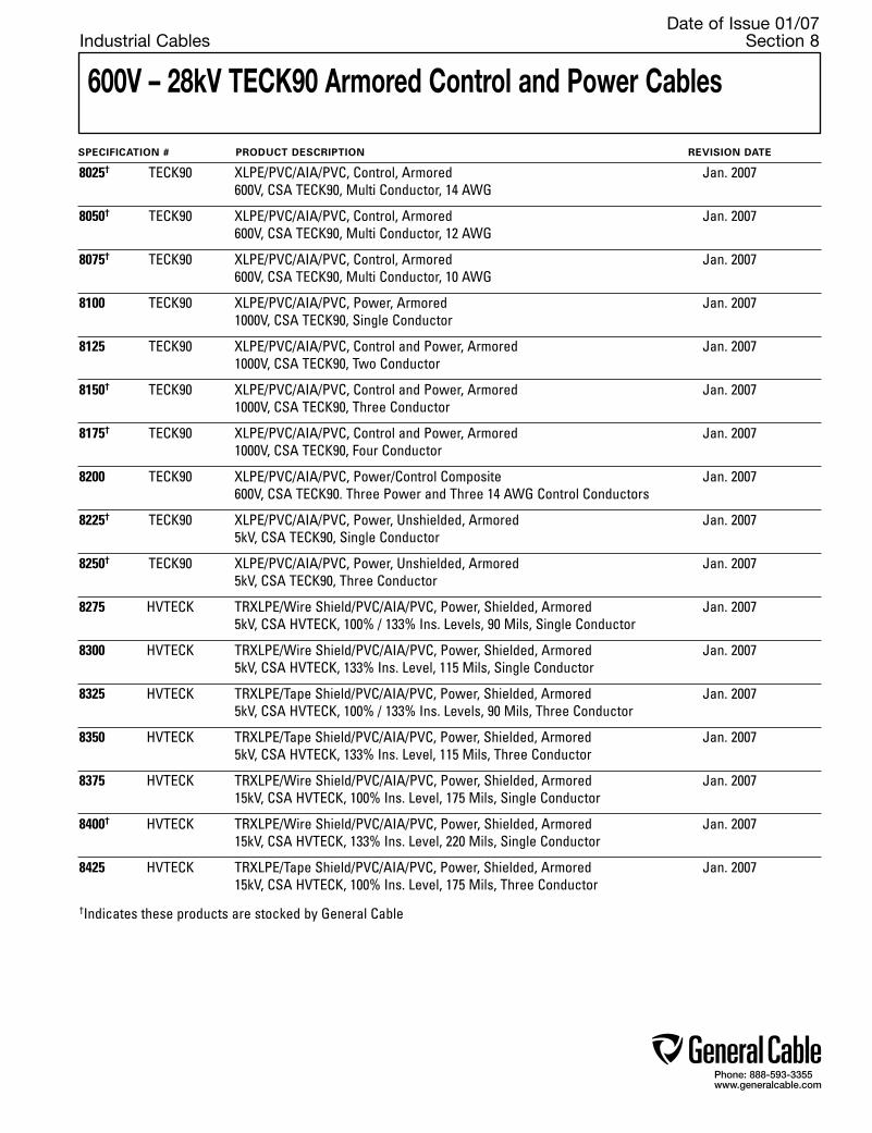
Phone: 888-593-3355www.generalcable.com
Date of Issue 01/07Industrial Cables Section 8
600V – 28kV TECK90 Armored Control and Power Cables
SPECIFICATION # PRODUCT DESCRIPTION REVISION DATE
8025† TECK90 XLPE/PVC/AIA/PVC, Control, Armored Jan. 2007 600V, CSA TECK90, Multi Conductor, 14 AWG
8050† TECK90 XLPE/PVC/AIA/PVC, Control, Armored Jan. 2007 600V, CSA TECK90, Multi Conductor, 12 AWG
8075† TECK90 XLPE/PVC/AIA/PVC, Control, Armored Jan. 2007 600V, CSA TECK90, Multi Conductor, 10 AWG
8100 TECK90 XLPE/PVC/AIA/PVC, Power, Armored Jan. 2007 1000V, CSA TECK90, Single Conductor
8125 TECK90 XLPE/PVC/AIA/PVC, Control and Power, Armored Jan. 2007 1000V, CSA TECK90, Two Conductor
8150† TECK90 XLPE/PVC/AIA/PVC, Control and Power, Armored Jan. 2007 1000V, CSA TECK90, Three Conductor
8175† TECK90 XLPE/PVC/AIA/PVC, Control and Power, Armored Jan. 2007 1000V, CSA TECK90, Four Conductor
8200 TECK90 XLPE/PVC/AIA/PVC, Power/Control Composite Jan. 2007 600V, CSA TECK90. Three Power and Three 14 AWG Control Conductors
8225† TECK90 XLPE/PVC/AIA/PVC, Power, Unshielded, Armored Jan. 2007 5kV, CSA TECK90, Single Conductor
8250† TECK90 XLPE/PVC/AIA/PVC, Power, Unshielded, Armored Jan. 2007 5kV, CSA TECK90, Three Conductor
8275 HVTECK TRXLPE/Wire Shield/PVC/AIA/PVC, Power, Shielded, Armored Jan. 2007 5kV, CSA HVTECK, 100% / 133% Ins. Levels, 90 Mils, Single Conductor
8300 HVTECK TRXLPE/Wire Shield/PVC/AIA/PVC, Power, Shielded, Armored Jan. 2007 5kV, CSA HVTECK, 133% Ins. Level, 115 Mils, Single Conductor
8325 HVTECK TRXLPE/Tape Shield/PVC/AIA/PVC, Power, Shielded, Armored Jan. 2007 5kV, CSA HVTECK, 100% / 133% Ins. Levels, 90 Mils, Three Conductor
8350 HVTECK TRXLPE/Tape Shield/PVC/AIA/PVC, Power, Shielded, Armored Jan. 2007 5kV, CSA HVTECK, 133% Ins. Level, 115 Mils, Three Conductor
8375 HVTECK TRXLPE/Wire Shield/PVC/AIA/PVC, Power, Shielded, Armored Jan. 2007 15kV, CSA HVTECK, 100% Ins. Level, 175 Mils, Single Conductor
8400† HVTECK TRXLPE/Wire Shield/PVC/AIA/PVC, Power, Shielded, Armored Jan. 2007 15kV, CSA HVTECK, 133% Ins. Level, 220 Mils, Single Conductor
8425 HVTECK TRXLPE/Tape Shield/PVC/AIA/PVC, Power, Shielded, Armored Jan. 2007 15kV, CSA HVTECK, 100% Ins. Level, 175 Mils, Three Conductor
†Indicates these products are stocked by General Cable

Phone: 888-593-3355www.generalcable.com
Date of Issue 01/07Industrial Cables Section 8
600V – 28kV TECK90 Armored Control and Power Cables
SPECIFICATION # PRODUCT DESCRIPTION REVISION DATE
8450† HVTECK TRXLPE/Tape Shield/PVC/AIA/PVC, Power, Shielded, Armored Jan. 2007 15kV, CSA HVTECK, 133% Ins. Level, 220 Mils, Three Conductor
8475 HVTECK TRXLPE/Tape Shield/PVC/AIA/PVC, Power, Shielded, Armored Jan. 2007 25kV, CSA HVTECK, 100% Ins. Level, 260 Mils, Three Conductor
8500 HVTECK TRXLPE/Tape Shield/PVC/AIA/PVC, Power, Shielded, Armored Jan. 2007 25kV, CSA HVTECK, 133% Ins. Level, 320 Mils, Three Conductor
8525 HVTECK TRXLPE/Tape Shield/PVC/AIA/PVC, Power, Shielded, Armored Jan. 2007 28kV, CSA HVTECK, 133% Ins. Level, 345 Mils, Three Conductor
8550 VERTITECK® TECK90 XLPE/PVC/GSIA/PVC, Power, Unshielded, Armored Jan. 2007 1kV, CSA TECK90, Three Conductor
8575 VERTITECK® HVTECK XLPE/PVC/GSIA/PVC, Power, Unshielded, Armored Jan. 2007 5kV, CSA HVTECK, 90 Mils, Three Conductor
8600 VERTITECK® HVTECK TRXLPE/Tape Shield/PVC/GSIA/PVC, Power, Shielded, Armored Jan. 2007 15kV, CSA HVTECK, 133% Ins. Level, 220 Mils, Three Conductor
†Indicates these products are stocked by General Cable

Phone: 888-593-3355www.generalcable.com
Product Construction
Conductor:• 14 AWG bare copper Class B
compressed concentric round to ASTM B8
Insulation:• Cross-linked Polyethylene (XLPE) Type RW90• Color-coded: per ICEA Method 4; Individual
conductors colored Black with conductor number surface printed in contrasting ink
Ground (Bonding) Conductor:• The conductor consists of one uninsulated
stranded bare copper conductor
Inner Jacket:• Flame-retardant, moisture- and sunlight-resistant
Polyvinyl Chloride (PVC)—Black
Armor:• Aluminum Interlocked Armor (AIA)
Overall Jacket:• ACID-FLAME-CHECK✓✓® flame-retardant,
moisture- and sunlight-resistant Polyvinyl Chloride (PVC)—Black
Print:• General Cable® ACID-FLAME-CHECK ✓✓®
AG14 FT1 FT4 HL TECK90 XLPE (-40˚C)#/C SIZE (14 AWG) 600V DIR BUR SUN RES CSA MONTH-YEAR SEQUENTIAL PRINT
Options:• Galvanized Steel Interlocked Armor (GSIA)• Other constructions available upon request
Applications:• For exposed and concealed wiring in dry, damp
or wet locations• For use in ventilated, non-ventilated and ladder-
type cable trays in dry, damp or wet locations• For direct earth burial (with protection as
required by inspection authority)• For wiring in all hazardous locations when used
with certified HL cable glands
Features:• Rated at 90˚C• Excellent crush, oil and chemical resistance• Provides long service life• Meets cold bend and impact tests at -40˚C
Compliances:• CSA Standard C22.2 No. 131 and No. 174• CSA Approval number: LR1781• CSA FT1 and FT4• IEEE 383 (70,000 BTU/hr)• UL 1581 (70,000 BTU/hr)• IEEE 1202 (70,000 BTU/hr) CSA FT4• ICEA T-30-520 (70,000 BTU/hr)• Hazardous Location Rating: HL• Meets EPA 40 CFR, part 261 for leachable lead
content per TCLP method• OSHA acceptable
Packaging:• For Canadian customers, lengths are provided
on returnable wood or steel reels that require a deposit. Extra charges apply for lagging, pulling eyes, paralleling and plexing
• For U.S. customers, material cut to length and shipped on non-returnable wood reels, while lengths in excess of 10,000 lbs. are provided on returnable steel reels that require a deposit. Extra charges apply for cuts less than 1000 ft., lagging, pulling eyes, paralleling and plexing
TECK90XLPE/PVC/AIA/PVC, Control, Armored600V, CSA TECK90, Multi Conductor, 14 AWG
CATALOGNUMBER
NO.OF
COND.
COND.SIZE
(AWG)
GROUNDWIRE SIZE
(AWG)
NOMINAL DIAMETER (OVER) INSULATION ARMOR CABLE AMPACITY**
(30˚C AMBIENT)
COPPERWEIGHT
lbs/ kg/ 1000ft km
NET WEIGHTW/ AL (STEEL) ARMOR
lbs/ kg/ 1000ft km INCHES mm INCHES mm INCHES mm
14 AWG—MULTI CONDUCTOR—30 MILS INS. (.76 mm), 600V
Dimensions and weights are nominal; subject to industry tolerances.*Non-stock item, minimum runs apply. Please consult Customer Service for price and delivery.**AMPACITY is based on CE Code Part 1: Table 2 for 3 conductors in raceway (conduit). Ampacity of 4 conductor cable is based on 3 current carrying conductors and 1 neutral. Ampacity at 5 or more conductors is modified by table 5C.
SPEC 8025January, 2007
2 14 14 0.13 3.4 0.58 14.8 0.67 16.9 39 58 195 (310) 290 (462) 15 3 14 14 0.13 3.4 0.60 15.4 0.69 17.4 52 78 226 (346) 336 (515) 15 4 14 14 0.13 3.4 0.64 16.2 0.72 18.3 68 101 256 (385) 381 (573) 15 5 14 14 0.13 3.4 0.68 17.3 0.76 19.3 81 121 290 (430) 432 (640) 12 6 14 14 0.13 3.4 0.72 18.3 0.80 20.3 95 142 316 (464) 471 (691) 12 7 14 14 0.13 3.4 0.74 18.8 0.82 20.8 104 155 338 (490) 503 (730) 10.5 8 14 14 0.13 3.4 0.79 20.1 0.87 22.2 117 174 373 (537) 555 (799) 10.5 10 14 14 0.13 3.4 0.88 22.3 0.96 24.3 149 222 451 (637) 671 (948) 10.5 12 14 14 0.13 3.4 0.90 23.0 0.99 25.0 176 262 511 (702) 761 (1045) 10.5 15 14 14 0.13 3.4 0.96 24.3 1.04 26.3 217 323 586 (791) 872 (1177) 10.5 20 14 14 0.13 3.4 1.13 28.7 1.21 30.8 285 424 789 (1117) 1174 (1662) 10.5 25 14 14 0.13 3.4 1.22 30.9 1.30 33.0 337 502 958 (1315) 1426 (1957) 9 30 14 14 0.13 3.4 1.28 32.5 1.36 34.6 402 599 1015 (1390) 1511 (2069) 9 40 14 14 0.13 3.4 1.40 35.6 1.48 37.7 531 791 1234 (1649) 1837 (2454) 9 50 14 14 0.13 3.4 1.52 38.5 1.60 40.6 661 984 1463 (1916) 2178 (2851) 7.5
780220780250780280794540792940780310330090792960792980793000780290
308190* 333750
330280* 299980*

Phone: 888-593-3355www.generalcable.com
TECK90XLPE/PVC/AIA/PVC, Control, Armored600V, CSA TECK90, Multi Conductor, 12 AWG
Product Construction
Conductor:• 12 AWG bare copper Class B
compressed concentric round to ASTM B8
Insulation:• Cross-linked Polyethylene (XLPE) Type RW90• Color-coded: per ICEA Method 4; Individual
conductors colored Black with conductor number surface printed in contrasting ink
Ground (Bonding) Conductor:• The conductor consists of one uninsulated
stranded bare copper conductor
Inner Jacket:• Flame-retardant, moisture- and sunlight-resistant
Polyvinyl Chloride (PVC)—Black
Armor:• Aluminum Interlocked Armor (AIA)
Overall Jacket:• ACID-FLAME-CHECK✓✓® flame-retardant,
moisture- and sunlight-resistant Polyvinyl Chloride (PVC)—Black
Print:• General Cable® ACID-FLAME-CHECK ✓✓®
AG14 FT1 FT4 HL TECK90 XLPE (-40˚C)#/C SIZE (12 AWG) 600V DIR BUR SUN RES CSA MONTH-YEAR SEQUENTIAL PRINT
Options:• Galvanized Steel Interlocked Armor (GSIA)• Other constructions available upon request
Applications:• For exposed and concealed wiring in dry, damp
or wet locations• For use in ventilated, non-ventilated and ladder-
type cable trays in dry, damp or wet locations• For direct earth burial (with protection as
required by inspection authority)• For wiring in all hazardous locations when used
with certified HL cable glands
Features:• Rated at 90˚C• Excellent crush, oil and chemical resistance• Provides long service life• Meets cold bend and impact tests at -40˚C
Compliances:• CSA Standard C22.2 No. 131 and No. 174• CSA Approval number: LR1781• CSA FT1 and FT4• IEEE 383 (70,000 BTU/hr)• UL 1581 (70,000 BTU/hr)• IEEE 1202 (70,000 BTU/hr) CSA FT4• ICEA T-30-520 (70,000 BTU/hr)• Hazardous Location Rating: HL• Meets EPA 40 CFR, part 261 for leachable lead
content per TCLP method• OSHA acceptable
Packaging:• For Canadian customers, lengths are provided
on returnable wood or steel reels that require a deposit. Extra charges apply for lagging, pulling eyes, paralleling and plexing
• For U.S. customers, material cut to length and shipped on non-returnable wood reels, while lengths in excess of 10,000 lbs. are provided on returnable steel reels that require a deposit. Extra charges apply for cuts less than 1000 ft., lagging, pulling eyes, paralleling and plexing
CATALOGNUMBER
NO.OF
COND.
COND.SIZE
(AWG)
GROUNDWIRE SIZE
(AWG)
NOMINAL DIAMETER (OVER) INSULATION ARMOR CABLE AMPACITY**
(30˚C AMBIENT)
COPPERWEIGHT
lbs/ kg/ 1000ft km
NET WEIGHTW/ AL (STEEL) ARMOR
lbs/ kg/ 1000ft km INCHES mm INCHES mm INCHES mm
12 AWG—MULTI CONDUCTOR—30 MILS INS. (.76 mm), 600V
Dimensions and weights are nominal; subject to industry tolerances.*Non-stock item, minimum runs apply. Please consult Customer Service for price and delivery.**AMPACITY is based on CE Code Part 1: Table 2 for 3 conductors in raceway (conduit). Ampacity of 4 conductor cable is based on 3 current carrying conductors and 1 neutral. Ampacity at 5 or more conductors is modified by table 5C.
SPEC 8050January, 2007
2 12 14 0.15 3.9 0.62 15.8 0.70 17.9 55 82 228 (352) 340 (524) 20 3 12 14 0.15 3.9 0.65 16.4 0.73 18.5 75 112 254 (386) 378 (575) 20 4 12 14 0.15 3.9 0.69 17.4 0.77 19.5 96 143 293 (434) 436 (646) 20 5 12 14 0.15 3.9 0.73 18.5 0.81 20.6 116 173 350 (501) 521 (746) 16 6 12 14 0.15 3.9 0.81 20.5 0.89 22.5 137 204 416 (585) 619 (871) 16 7 12 14 0.15 3.9 0.83 21.0 0.91 23.1 157 234 443 (616) 660 (917) 14 8 12 14 0.15 3.9 0.86 21.7 0.94 23.8 177 264 492 (673) 732 (1002) 14 10 12 14 0.15 3.9 0.95 24.2 1.04 26.2 219 326 555 (757) 826 (1127) 14 12 12 14 0.15 3.9 1.01 25.7 1.10 27.8 261 389 653 (942) 972 (1402) 14 15 12 14 0.15 3.9 1.07 27.2 1.16 29.3 322 480 757 (1065) 1127 (1585) 14 20 12 14 0.15 3.9 1.23 31.3 1.32 33.4 424 631 986 (1346) 1468 (2003) 14 25 12 14 0.15 3.9 1.33 33.8 1.42 35.9 527 785 1210 (1602) 1801 (2384) 12 30 12 14 0.15 3.9 1.40 35.6 1.49 37.7 630 938 1320 (1735) 1965 (2582) 12 40 12 14 0.15 3.9 1.54 39.1 1.64 41.6 837 1246 1725 (2185) 2567 (3252) 12 50 12 14 0.15 3.9 1.67 42.4 1.77 44.9 1044 1553 2055 (2556) 3058 (3804) 10
780210780240780320312910
331190* 315020* 311560* 304030* 331130* 312990* 299950* 307470* 318730* 346880* 346890*

Phone: 888-593-3355www.generalcable.com
Product Construction
Conductor:• 10 AWG bare copper Class B
compressed concentric round to ASTM B8
Insulation:• Cross-linked Polyethylene (XLPE) Type RW90• Color-coded: per ICEA Method 4; Individual
conductors colored Black with conductor number surface printed in contrasting ink
Ground (Bonding) Conductor:• The conductor consists of one uninsulated
stranded bare copper conductor• Color-coded: per ICEA Method 4; Individual
conductors colored Black with conductor number surface printed in contrasting ink
Inner Jacket:• Flame-retardant, moisture- and sunlight-resistant
Polyvinyl Chloride (PVC)—Black
Armor:• Aluminum Interlocked Armor (AIA)
Overall Jacket:• ACID-FLAME-CHECK✓✓® flame-retardant,
moisture- and sunlight-resistant Polyvinyl Chloride (PVC)—Black
Print:• General Cable® ACID-FLAME-CHECK ✓✓®
AG14 FT1 FT4 HL TECK90 XLPE (-40˚C)#/C SIZE (10 AWG) 600V DIR BUR SUN RES CSA MONTH-YEAR SEQUENTIAL PRINT
Options:• Galvanized Steel Interlocked Armor (GSIA)• Other constructions available upon request
Applications:• For exposed and concealed wiring in dry, damp
or wet locations• For use in ventilated, non-ventilated and ladder-
type cable trays in dry, damp or wet locations• For direct earth burial (with protection as
required by inspection authority)• For wiring in all hazardous locations when used
with certified HL cable glands
Features:• Rated at 90˚C• Excellent crush, oil and chemical resistance• Provides long service life• Meets cold bend and impact tests at -40˚C
Compliances:• CSA Standard C22.2 No. 131 and No. 174• CSA Approval number: LR1781• CSA FT1 and FT4• IEEE 383 (70,000 BTU/hr)• UL 1581 (70,000 BTU/hr)• IEEE 1202 (70,000 BTU/hr) CSA FT4• ICEA T-30-520 (70,000 BTU/hr)• Hazardous Location Rating: HL• Meets EPA 40 CFR, part 261 for leachable lead
content per TCLP method• OSHA acceptable
Packaging:• For Canadian customers, lengths are provided
on returnable wood or steel reels that require a deposit. Extra charges apply for lagging, pulling eyes, paralleling and plexing
• For U.S. customers, material cut to length and shipped on non-returnable wood reels, while lengths in excess of 10,000 lbs. are provided on returnable steel reels that require a deposit. Extra charges apply for cuts less than 1000 ft., lagging, pulling eyes, paralleling and plexing
TECK90XLPE/PVC/AIA/PVC, Control, Armored600V, CSA TECK90, Multi Conductor, 10 AWG
CATALOGNUMBER
NO.OF
COND.
COND.SIZE
(AWG)
GROUNDWIRE SIZE
(AWG)
NOMINAL DIAMETER (OVER) INSULATION ARMOR CABLE AMPACITY**
(30˚C AMBIENT)
COPPERWEIGHT
lbs/ kg/ 1000ft km
NET WEIGHTW/ AL (STEEL) ARMOR
lbs/ kg/ 1000ft km INCHES mm INCHES mm INCHES mm
10 AWG—MULTI CONDUCTOR—30 MILS INS. (.76 mm), 600V
Dimensions and weights are nominal; subject to industry tolerances.*Non-stock item, minimum runs apply. Please consult Customer Service for price and delivery.**AMPACITY is based on CE Code Part 1: Table 2 for 3 conductors in raceway (conduit). Ampacity of 4 conductor cable is based on 3 current carrying conductors and 1 neutral. Ampacity at 5 or more conductors is modified by table 5C.
SPEC 8075January, 2007
2 10 12 0.18 4.5 0.67 17.0 0.75 19.0 87 130 275 (411) 410 (612) 30 3 10 12 0.18 4.5 0.70 17.7 0.78 19.7 119 177 327 (470) 487 (700) 30 4 10 12 0.18 4.5 0.74 18.8 0.83 20.9 150 223 413 (565) 615 (841) 30 5 10 12 0.18 4.5 0.82 20.9 0.91 22.9 184 274 473 (644) 704 (959) 24 6 10 12 0.18 4.5 0.88 22.2 0.96 24.3 217 323 532 (718) 792 (1069) 24 7 10 12 0.18 4.5 0.90 22.9 0.99 25.0 248 369 623 (813) 928 (1210) 21 8 10 12 0.18 4.5 0.93 23.6 1.02 25.7 282 420 791 (989) 1177 (1472) 21 10 10 12 0.18 4.5 1.08 27.3 1.16 29.4 348 518 911 (1223) 1356 (1820) 21 12 10 12 0.18 4.5 1.15 29.2 1.23 31.3 414 617 1063 (1397) 1582 (2079) 21 15 10 12 0.18 4.5 1.22 30.9 1.30 33.0 512 762 1328 (1685) 1977 (2508) 21 20 10 12 0.18 4.5 1.36 34.4 1.44 36.5 675 1005 1327 (1729) 1975 (2573) 21 25 10 12 0.18 4.5 1.47 37.3 1.55 39.4 835 1243 1565 (2002) 2329 (2979) 18 30 10 12 0.18 4.5 1.55 39.4 1.65 41.8 998 1493 1799 (2262) 2677 (3366) 18 40 10 12 0.18 4.5 1.71 43.4 1.81 45.9 1321 1966 2293 (2807) 3412 (4177) 18 50 10 12 0.18 4.5 1.87 47.5 1.97 49.9 1648 2453 2784 (3348) 4143 (4982) 15
780200780230780270
319480* 333160* 346870* 318740* 311570* 317890* 318750* 308180* 307450* 293570* 307460* 346900*

Phone: 888-593-3355www.generalcable.com
TECK90XLPE/PVC/AIA/PVC, Power, Armored1000V, CSA TECK90, Single Conductor
Dimensions and weights are nominal; subject to industry tolerances.*Non-stock item, minimum runs apply. Please consult Customer Service for price and delivery.**AMPACITY is based on CE Code Part 1: Table 1 (single conductor in free air) and Rule 4-004.
Product Construction
Conductor:• 6 AWG thru 1000 kcmil bare copper compact
Class B strand
Insulation:• Cross-linked Polyethylene (XLPE) Type RW90• Color-coded: Black
Ground (Bonding) Conductor:• The conductor is a concentric serving of solid
bare copper wires applied over the insulation
Inner Jacket:• Flame-retardant, moisture- and sunlight-resistant
Polyvinyl Chloride (PVC)—Black
Armor:• Aluminum Interlocked Armor (AIA)
Overall Jacket:• ACID-FLAME-CHECK✓✓® flame-retardant,
moisture- and sunlight-resistant Polyvinyl Chloride (PVC)—Black
Print:• GENERAL CABLE® ACID-FLAME-CHECK ✓✓®
AG14 FT1 FT4 HL TECK90 XLPE (-40˚C)1/C SIZE (AWG OR KCMIL) 1000V DIR BUR SUN RES CSA MONTH-YEAR SEQUENTIAL PRINT
Options:• Other constructions available upon request
Applications:• For exposed and concealed wiring in dry, damp
or wet locations• For use in ventilated, non-ventilated and ladder-
type cable trays in dry, damp or wet locations• For direct earth burial (with protection as
required by inspection authority)• For wiring in all hazardous locations when used
with certified HL cable glands
Features:• Rated at 90˚C• Excellent crush, oil and chemical resistance• Provides long service life• Cost effective alternative to installations in
conduit• Meets cold bend and impact tests at -40˚C
Compliances:• CSA Standard C22.2 No. 131 and No. 174• CSA Approval number: LR1781• CSA FT1 and FT4• IEEE 383 (70,000 BTU/hr)• UL 1581 (70,000 BTU/hr)• IEEE 1202 (70,000 BTU/hr) CSA FT4 • ICEA T-30-520 (70,000 BTU/hr)• Hazardous Location Rating: HL• Meets EPA 40 CFR, part 261 for leachable lead
content per TCLP method• OSHA acceptable
Packaging:• For Canadian customers, lengths are provided
on returnable wood or steel reels that require a deposit. Extra charges apply for lagging, pulling eyes, paralleling and plexing
• For U.S. customers, material cut to length and shipped on non-returnable wood reels, while lengths in excess of 10,000 lbs. are provided on returnable steel reels that require a deposit. Extra charges apply for cuts less than 1000 ft., lagging, pulling eyes, paralleling and plexing
CATALOGNUMBER
NO.OF
COND.
COND.SIZE AWG/kcmil
GROUNDWIRESIZE
(AWG)
MIN. AVG INS.THICKNESS
INCHES mm
NOMINAL DIAMETER (OVER) INSULATION ARMOR CABLE AMPACITY**
(30˚C AMBIENT)
COPPERWEIGHT
lbs/ kg/ 1000ft km
NET WEIGHT lbs/1000ft kg/km INCHES mm INCHES mm INCHES mm
6 AWG THRU 1000 kcmil—SINGLE CONDUCTOR—1000V
( )
SPEC 8100January, 2007
1 6 8 .060 1.52 0.31 7.8 0.68 17.3 0.77 19.6 137 204 320 470 100
1 4 6 .060 1.52 0.35 8.8 0.73 18.6 0.81 20.6 211 314 410 610 135
1 3 6 .060 1.52 0.38 9.8 0.76 19.3 0.84 21.4 244 363 450 680 155
1 2 6 .060 1.52 0.42 10.5 0.78 19.8 0.87 22.1 286 426 510 760 180
1 1 4 .080 2.03 0.49 12.5 0.88 22.4 0.96 24.4 390 581 680 1010 210
1 1/0 4 .080 2.03 0.53 13.5 0.91 23.2 1.00 25.4 458 682 760 1130 245
1 2/0 4 .080 2.03 0.58 14.7 0.95 24.1 1.04 26.4 544 810 860 1280 285
1 3/0 3 .080 2.03 0.63 15.9 1.03 26.2 1.12 28.5 685 1020 1080 1610 330
1 4/0 3 .080 2.03 0.69 17.5 1.08 27.5 1.17 29.7 820 1220 1270 1890 385
1 250 2 .090 2.29 0.75 19.2 1.21 30.8 1.29 32.8 980 1459 1490 2210 425
1 350 1 .090 2.29 0.86 21.7 1.30 33.0 1.39 35.3 1340 1994 1910 2840 530
1 500 1/0 .090 2.29 0.99 25.0 1.42 36.1 1.51 38.4 1750 2604 2510 3740 660
1 750 2/0 .090 2.29 1.16 29.4 1.59 40.4 1.69 43.0 2570 3825 3510 5230 845
1 1000 2/0 .090 2.29 1.31 33.2 1.81 46.0 1.90 48.3 3340 4970 4430 6590 1000
11288.040600*11288.050400*11288.030300*11288.050200*11288.050100*11288.035100*11288.035200*11288.035300*11288.02540011288.02600011288.03620011288.02650011288.02700011288.027500
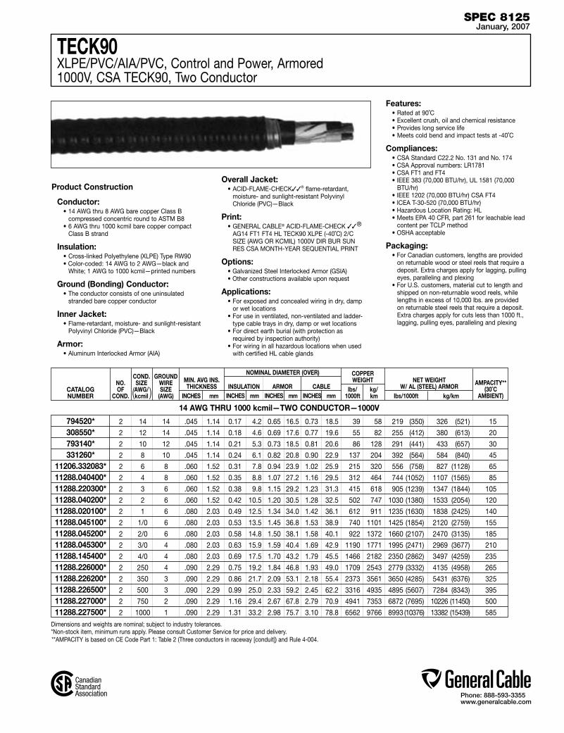
Phone: 888-593-3355www.generalcable.com
TECK90XLPE/PVC/AIA/PVC, Control and Power, Armored1000V, CSA TECK90, Two Conductor
Dimensions and weights are nominal; subject to industry tolerances.*Non-stock item, minimum runs apply. Please consult Customer Service for price and delivery.
Product Construction
Conductor:• 14 AWG thru 8 AWG bare copper Class B
compressed concentric round to ASTM B8• 6 AWG thru 1000 kcmil bare copper compact
Class B strand
Insulation:• Cross-linked Polyethylene (XLPE) Type RW90• Color-coded: 14 AWG to 2 AWG—black and
White; 1 AWG to 1000 kcmil—printed numbers
Ground (Bonding) Conductor:• The conductor consists of one uninsulated
stranded bare copper conductor
Inner Jacket:• Flame-retardant, moisture- and sunlight-resistant
Polyvinyl Chloride (PVC)—Black
Armor:• Aluminum Interlocked Armor (AIA)
Overall Jacket:• ACID-FLAME-CHECK✓✓® flame-retardant,
moisture- and sunlight-resistant Polyvinyl Chloride (PVC)—Black
Print:• GENERAL CABLE® ACID-FLAME-CHECK ✓✓®
AG14 FT1 FT4 HL TECK90 XLPE (-40˚C) 2/C SIZE (AWG OR KCMIL) 1000V DIR BUR SUN RES CSA MONTH-YEAR SEQUENTIAL PRINT
Options:• Galvanized Steel Interlocked Armor (GSIA)• Other constructions available upon request
Applications:• For exposed and concealed wiring in dry, damp
or wet locations• For use in ventilated, non-ventilated and ladder-
type cable trays in dry, damp or wet locations• For direct earth burial (with protection as
required by inspection authority)• For wiring in all hazardous locations when used
with certified HL cable glands
Features:• Rated at 90˚C• Excellent crush, oil and chemical resistance• Provides long service life• Meets cold bend and impact tests at -40˚C
Compliances:• CSA Standard C22.2 No. 131 and No. 174• CSA Approval numbers: LR1781• CSA FT1 and FT4• IEEE 383 (70,000 BTU/hr), UL 1581 (70,000
BTU/hr)• IEEE 1202 (70,000 BTU/hr) CSA FT4• ICEA T-30-520 (70,000 BTU/hr)• Hazardous Location Rating: HL• Meets EPA 40 CFR, part 261 for leachable lead
content per TCLP method• OSHA acceptable
Packaging:• For Canadian customers, lengths are provided
on returnable wood or steel reels that require a deposit. Extra charges apply for lagging, pulling eyes, paralleling and plexing
• For U.S. customers, material cut to length and shipped on non-returnable wood reels, while lengths in excess of 10,000 lbs. are provided on returnable steel reels that require a deposit. Extra charges apply for cuts less than 1000 ft., lagging, pulling eyes, paralleling and plexing
**AMPACITY is based on CE Code Part 1: Table 2 (Three conductors in raceway [conduit]) and Rule 4-004.
CATALOGNUMBER
NO.OF
COND.
COND.SIZE AWG/kcmil
GROUNDWIRESIZE
(AWG)
MIN. AVG INS.THICKNESS
INCHES mm
NOMINAL DIAMETER (OVER) INSULATION ARMOR CABLE AMPACITY**
(30˚C AMBIENT)
COPPERWEIGHT
lbs/ kg/ 1000ft km
NET WEIGHTW/ AL (STEEL) ARMOR
lbs/1000ft kg/km INCHES mm INCHES mm INCHES mm
14 AWG THRU 1000 kcmil—TWO CONDUCTOR—1000V
( )
SPEC 8125January, 2007
2 14 14 .045 1.14 0.17 4.2 0.65 16.5 0.73 18.5 39 58 219 (350) 326 (521) 15
2 12 14 .045 1.14 0.18 4.6 0.69 17.6 0.77 19.6 55 82 255 (412) 380 (613) 20
2 10 12 .045 1.14 0.21 5.3 0.73 18.5 0.81 20.6 86 128 291 (441) 433 (657) 30
2 8 10 .045 1.14 0.24 6.1 0.82 20.8 0.90 22.9 137 204 392 (564) 584 (840) 45
2 6 8 .060 1.52 0.31 7.8 0.94 23.9 1.02 25.9 215 320 556 (758) 827 (1128) 65
2 4 8 .060 1.52 0.35 8.8 1.07 27.2 1.16 29.5 312 464 744 (1052) 1107 (1565) 85
2 3 6 .060 1.52 0.38 9.8 1.15 29.2 1.23 31.3 415 618 905 (1239) 1347 (1844) 105
2 2 6 .060 1.52 0.42 10.5 1.20 30.5 1.28 32.5 502 747 1030 (1380) 1533 (2054) 120
2 1 6 .080 2.03 0.49 12.5 1.34 34.0 1.42 36.1 612 911 1235 (1630) 1838 (2425) 140
2 1/0 6 .080 2.03 0.53 13.5 1.45 36.8 1.53 38.9 740 1101 1425 (1854) 2120 (2759) 155
2 2/0 6 .080 2.03 0.58 14.8 1.50 38.1 1.58 40.1 922 1372 1660 (2107) 2470 (3135) 185
2 3/0 4 .080 2.03 0.63 15.9 1.59 40.4 1.69 42.9 1190 1771 1995 (2471) 2969 (3677) 210
2 4/0 4 .080 2.03 0.69 17.5 1.70 43.2 1.79 45.5 1466 2182 2350 (2862) 3497 (4259) 235
2 250 4 .090 2.29 0.75 19.2 1.84 46.8 1.93 49.0 1709 2543 2779 (3332) 4135 (4958) 265
2 350 3 .090 2.29 0.86 21.7 2.09 53.1 2.18 55.4 2373 3561 3650 (4285) 5431 (6376) 325
2 500 3 .090 2.29 0.99 25.0 2.33 59.2 2.45 62.2 3316 4935 4895 (5607) 7284 (8343) 395
2 750 2 .090 2.29 1.16 29.4 2.67 67.8 2.79 70.9 4941 7353 6872 (7695) 10226 (11450) 500
2 1000 1 .090 2.29 1.31 33.2 2.98 75.7 3.10 78.8 6562 9766 8993 (10376) 13382 (15439) 585
794520*308550* 793140* 331260*
11206.332083*11288.040400*11288.220300*11288.040200*11288.020100*11288.045100*11288.045200*11288.045300*11288.145400*11288.226000*11288.226200*11288.226500*11288.227000*11288.227500*
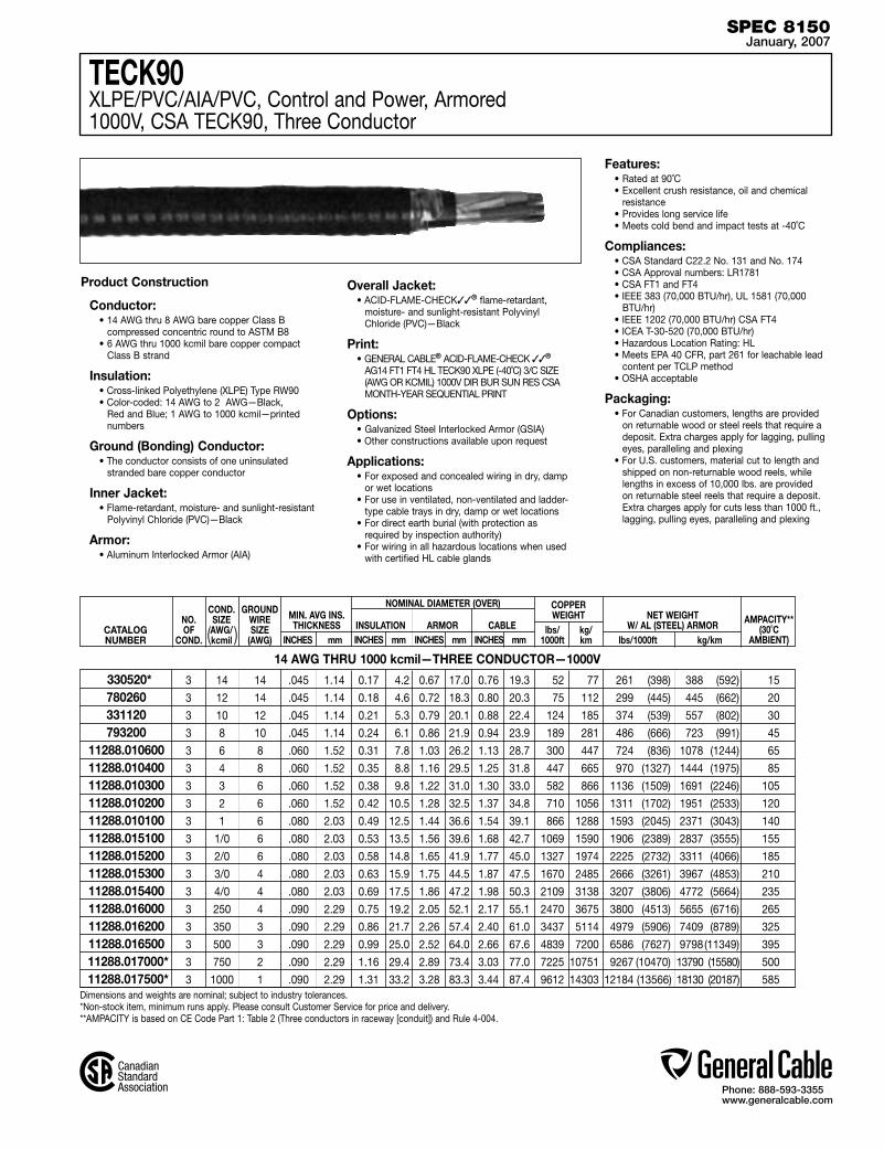
Phone: 888-593-3355www.generalcable.com
Dimensions and weights are nominal; subject to industry tolerances.*Non-stock item, minimum runs apply. Please consult Customer Service for price and delivery.**AMPACITY is based on CE Code Part 1: Table 2 (Three conductors in raceway [conduit]) and Rule 4-004.
CATALOGNUMBER
NO.OF
COND.
COND.SIZE AWG/kcmil
GROUNDWIRESIZE
(AWG)
MIN. AVG INS.THICKNESS
INCHES mm
NOMINAL DIAMETER (OVER) INSULATION ARMOR CABLE AMPACITY**
(30˚C AMBIENT)
COPPERWEIGHT
lbs/ kg/ 1000ft km
NET WEIGHTW/ AL (STEEL) ARMOR
lbs/1000ft kg/km INCHES mm INCHES mm INCHES mm
14 AWG THRU 1000 kcmil—THREE CONDUCTOR—1000V
Product Construction
Conductor:• 14 AWG thru 8 AWG bare copper Class B
compressed concentric round to ASTM B8• 6 AWG thru 1000 kcmil bare copper compact
Class B strand
Insulation:• Cross-linked Polyethylene (XLPE) Type RW90• Color-coded: 14 AWG to 2 AWG—Black,
Red and Blue; 1 AWG to 1000 kcmil—printed numbers
Ground (Bonding) Conductor:• The conductor consists of one uninsulated
stranded bare copper conductor
Inner Jacket:• Flame-retardant, moisture- and sunlight-resistant
Polyvinyl Chloride (PVC)—Black
Armor:• Aluminum Interlocked Armor (AIA)
Overall Jacket:• ACID-FLAME-CHECK✓✓® flame-retardant,
moisture- and sunlight-resistant Polyvinyl Chloride (PVC)—Black
Print:• GENERAL CABLE® ACID-FLAME-CHECK ✓✓®
AG14 FT1 FT4 HL TECK90 XLPE (-40˚C) 3/C SIZE (AWG OR KCMIL) 1000V DIR BUR SUN RES CSA MONTH-YEAR SEQUENTIAL PRINT
Options:• Galvanized Steel Interlocked Armor (GSIA)• Other constructions available upon request
Applications:• For exposed and concealed wiring in dry, damp
or wet locations• For use in ventilated, non-ventilated and ladder-
type cable trays in dry, damp or wet locations• For direct earth burial (with protection as
required by inspection authority)• For wiring in all hazardous locations when used
with certified HL cable glands
Features:• Rated at 90˚C• Excellent crush resistance, oil and chemical
resistance• Provides long service life• Meets cold bend and impact tests at -40˚C
Compliances:• CSA Standard C22.2 No. 131 and No. 174• CSA Approval numbers: LR1781• CSA FT1 and FT4• IEEE 383 (70,000 BTU/hr), UL 1581 (70,000
BTU/hr)• IEEE 1202 (70,000 BTU/hr) CSA FT4 • ICEA T-30-520 (70,000 BTU/hr)• Hazardous Location Rating: HL• Meets EPA 40 CFR, part 261 for leachable lead
content per TCLP method• OSHA acceptable
Packaging:• For Canadian customers, lengths are provided
on returnable wood or steel reels that require a deposit. Extra charges apply for lagging, pulling eyes, paralleling and plexing
• For U.S. customers, material cut to length and shipped on non-returnable wood reels, while lengths in excess of 10,000 lbs. are provided on returnable steel reels that require a deposit. Extra charges apply for cuts less than 1000 ft., lagging, pulling eyes, paralleling and plexing
( )
TECK90XLPE/PVC/AIA/PVC, Control and Power, Armored1000V, CSA TECK90, Three Conductor
SPEC 8150January, 2007
3 14 14 .045 1.14 0.17 4.2 0.67 17.0 0.76 19.3 52 77 261 (398) 388 (592) 15
3 12 14 .045 1.14 0.18 4.6 0.72 18.3 0.80 20.3 75 112 299 (445) 445 (662) 20
3 10 12 .045 1.14 0.21 5.3 0.79 20.1 0.88 22.4 124 185 374 (539) 557 (802) 30
3 8 10 .045 1.14 0.24 6.1 0.86 21.9 0.94 23.9 189 281 486 (666) 723 (991) 45
3 6 8 .060 1.52 0.31 7.8 1.03 26.2 1.13 28.7 300 447 724 (836) 1078 (1244) 65
3 4 8 .060 1.52 0.35 8.8 1.16 29.5 1.25 31.8 447 665 970 (1327) 1444 (1975) 85
3 3 6 .060 1.52 0.38 9.8 1.22 31.0 1.30 33.0 582 866 1136 (1509) 1691 (2246) 105
3 2 6 .060 1.52 0.42 10.5 1.28 32.5 1.37 34.8 710 1056 1311 (1702) 1951 (2533) 120
3 1 6 .080 2.03 0.49 12.5 1.44 36.6 1.54 39.1 866 1288 1593 (2045) 2371 (3043) 140
3 1/0 6 .080 2.03 0.53 13.5 1.56 39.6 1.68 42.7 1069 1590 1906 (2389) 2837 (3555) 155
3 2/0 6 .080 2.03 0.58 14.8 1.65 41.9 1.77 45.0 1327 1974 2225 (2732) 3311 (4066) 185
3 3/0 4 .080 2.03 0.63 15.9 1.75 44.5 1.87 47.5 1670 2485 2666 (3261) 3967 (4853) 210
3 4/0 4 .080 2.03 0.69 17.5 1.86 47.2 1.98 50.3 2109 3138 3207 (3806) 4772 (5664) 235
3 250 4 .090 2.29 0.75 19.2 2.05 52.1 2.17 55.1 2470 3675 3800 (4513) 5655 (6716) 265
3 350 3 .090 2.29 0.86 21.7 2.26 57.4 2.40 61.0 3437 5114 4979 (5906) 7409 (8789) 325
3 500 3 .090 2.29 0.99 25.0 2.52 64.0 2.66 67.6 4839 7200 6586 (7627) 9798 (11349) 395
3 750 2 .090 2.29 1.16 29.4 2.89 73.4 3.03 77.0 7225 10751 9267 (10470) 13790 (15580) 500
3 1000 1 .090 2.29 1.31 33.2 3.28 83.3 3.44 87.4 9612 14303 12184 (13566) 18130 (20187) 585
330520*780260331120793200
11288.01060011288.01040011288.01030011288.01020011288.01010011288.01510011288.01520011288.01530011288.01540011288.01600011288.01620011288.016500
11288.017000* 11288.017500*
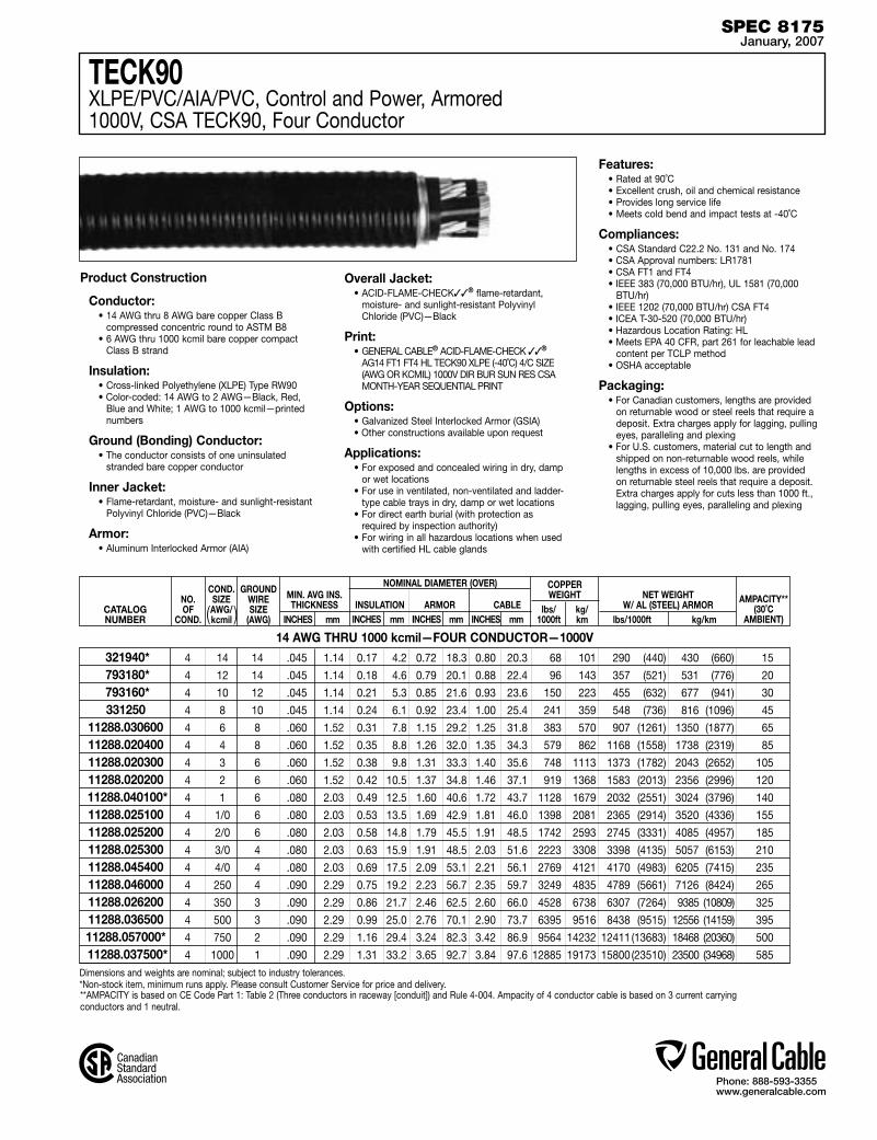
Phone: 888-593-3355www.generalcable.com
Dimensions and weights are nominal; subject to industry tolerances.*Non-stock item, minimum runs apply. Please consult Customer Service for price and delivery.
TECK90XLPE/PVC/AIA/PVC, Control and Power, Armored1000V, CSA TECK90, Four Conductor
**AMPACITY is based on CE Code Part 1: Table 2 (Three conductors in raceway [conduit]) and Rule 4-004. Ampacity of 4 conductor cable is based on 3 current carrying conductors and 1 neutral.
CATALOGNUMBER
NO.OF
COND.
COND.SIZE AWG/kcmil
GROUNDWIRESIZE
(AWG)
MIN. AVG INS.THICKNESS
INCHES mm
NOMINAL DIAMETER (OVER) INSULATION ARMOR CABLE AMPACITY**
(30˚C AMBIENT)
COPPERWEIGHT
lbs/ kg/ 1000ft km
NET WEIGHTW/ AL (STEEL) ARMOR
lbs/1000ft kg/km INCHES mm INCHES mm INCHES mm
14 AWG THRU 1000 kcmil—FOUR CONDUCTOR—1000V
Product Construction
Conductor:• 14 AWG thru 8 AWG bare copper Class B
compressed concentric round to ASTM B8• 6 AWG thru 1000 kcmil bare copper compact
Class B strand
Insulation:• Cross-linked Polyethylene (XLPE) Type RW90• Color-coded: 14 AWG to 2 AWG—Black, Red,
Blue and White; 1 AWG to 1000 kcmil—printed numbers
Ground (Bonding) Conductor:• The conductor consists of one uninsulated
stranded bare copper conductor
Inner Jacket:• Flame-retardant, moisture- and sunlight-resistant
Polyvinyl Chloride (PVC)—Black
Armor:• Aluminum Interlocked Armor (AIA)
Overall Jacket:• ACID-FLAME-CHECK✓✓® flame-retardant,
moisture- and sunlight-resistant Polyvinyl Chloride (PVC)—Black
Print:• GENERAL CABLE® ACID-FLAME-CHECK ✓✓®
AG14 FT1 FT4 HL TECK90 XLPE (-40˚C) 4/C SIZE (AWG OR KCMIL) 1000V DIR BUR SUN RES CSA MONTH-YEAR SEQUENTIAL PRINT
Options:• Galvanized Steel Interlocked Armor (GSIA)• Other constructions available upon request
Applications:• For exposed and concealed wiring in dry, damp
or wet locations• For use in ventilated, non-ventilated and ladder-
type cable trays in dry, damp or wet locations• For direct earth burial (with protection as
required by inspection authority)• For wiring in all hazardous locations when used
with certified HL cable glands
Features:• Rated at 90˚C• Excellent crush, oil and chemical resistance• Provides long service life• Meets cold bend and impact tests at -40˚C
Compliances:• CSA Standard C22.2 No. 131 and No. 174• CSA Approval numbers: LR1781• CSA FT1 and FT4• IEEE 383 (70,000 BTU/hr), UL 1581 (70,000
BTU/hr)• IEEE 1202 (70,000 BTU/hr) CSA FT4• ICEA T-30-520 (70,000 BTU/hr)• Hazardous Location Rating: HL• Meets EPA 40 CFR, part 261 for leachable lead
content per TCLP method• OSHA acceptable
Packaging:• For Canadian customers, lengths are provided
on returnable wood or steel reels that require a deposit. Extra charges apply for lagging, pulling eyes, paralleling and plexing
• For U.S. customers, material cut to length and shipped on non-returnable wood reels, while lengths in excess of 10,000 lbs. are provided on returnable steel reels that require a deposit. Extra charges apply for cuts less than 1000 ft., lagging, pulling eyes, paralleling and plexing
( )
SPEC 8175January, 2007
4 14 14 .045 1.14 0.17 4.2 0.72 18.3 0.80 20.3 68 101 290 (440) 430 (660) 15
4 12 14 .045 1.14 0.18 4.6 0.79 20.1 0.88 22.4 96 143 357 (521) 531 (776) 20
4 10 12 .045 1.14 0.21 5.3 0.85 21.6 0.93 23.6 150 223 455 (632) 677 (941) 30
4 8 10 .045 1.14 0.24 6.1 0.92 23.4 1.00 25.4 241 359 548 (736) 816 (1096) 45
4 6 8 .060 1.52 0.31 7.8 1.15 29.2 1.25 31.8 383 570 907 (1261) 1350 (1877) 65
4 4 8 .060 1.52 0.35 8.8 1.26 32.0 1.35 34.3 579 862 1168 (1558) 1738 (2319) 85
4 3 6 .060 1.52 0.38 9.8 1.31 33.3 1.40 35.6 748 1113 1373 (1782) 2043 (2652) 105
4 2 6 .060 1.52 0.42 10.5 1.37 34.8 1.46 37.1 919 1368 1583 (2013) 2356 (2996) 120
4 1 6 .080 2.03 0.49 12.5 1.60 40.6 1.72 43.7 1128 1679 2032 (2551) 3024 (3796) 140
4 1/0 6 .080 2.03 0.53 13.5 1.69 42.9 1.81 46.0 1398 2081 2365 (2914) 3520 (4336) 155
4 2/0 6 .080 2.03 0.58 14.8 1.79 45.5 1.91 48.5 1742 2593 2745 (3331) 4085 (4957) 185
4 3/0 4 .080 2.03 0.63 15.9 1.91 48.5 2.03 51.6 2223 3308 3398 (4135) 5057 (6153) 210
4 4/0 4 .080 2.03 0.69 17.5 2.09 53.1 2.21 56.1 2769 4121 4170 (4983) 6205 (7415) 235
4 250 4 .090 2.29 0.75 19.2 2.23 56.7 2.35 59.7 3249 4835 4789 (5661) 7126 (8424) 265
4 350 3 .090 2.29 0.86 21.7 2.46 62.5 2.60 66.0 4528 6738 6307 (7264) 9385 (10809) 325
4 500 3 .090 2.29 0.99 25.0 2.76 70.1 2.90 73.7 6395 9516 8438 (9515) 12556 (14159) 395
4 750 2 .090 2.29 1.16 29.4 3.24 82.3 3.42 86.9 9564 14232 12411 (13683) 18468 (20360) 500
4 1000 1 .090 2.29 1.31 33.2 3.65 92.7 3.84 97.6 12885 19173 15800 (23510) 23500 (34968) 585
321940* 793180* 793160*331250
11288.03060011288.02040011288.02030011288.020200
11288.040100*11288.02510011288.02520011288.02530011288.04540011288.04600011288.02620011288.03650011288.057000* 11288.037500*
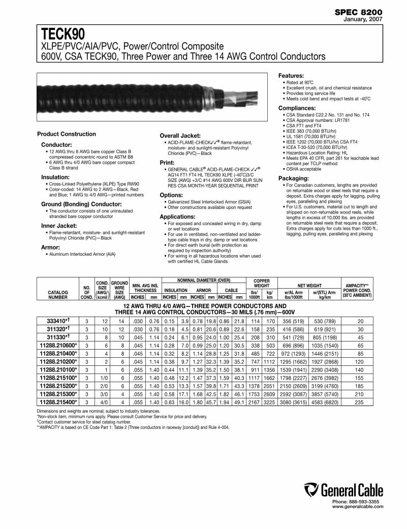
Phone: 888-593-3355www.generalcable.com
TECK90XLPE/PVC/AIA/PVC, Power/Control Composite 600V, CSA TECK90, Three Power and Three 14 AWG Control Conductors
Dimensions and weights are nominal; subject to industry tolerances.*Non-stock item, minimum runs apply. Please consult Customer Service for price and delivery.†Contact customer service for steel catalog number.**AMPACITY is based on CE Code Part 1: Table 2 (Three conductors in raceway [conduit]) and Rule 4-004.
Product Construction
Conductor:• 12 AWG thru 8 AWG bare copper Class B
compressed concentric round to ASTM B8• 6 AWG thru 4/0 AWG bare copper compact
Class B strand
Insulation:• Cross-Linked Polyethylene (XLPE) Type RW90• Color-coded: 14 AWG to 2 AWG—Black, Red
and Blue; 1 AWG to 4/0 AWG—printed numbers
Ground (Bonding) Conductor:• The conductor consists of one uninsulated
stranded bare copper conductor
Inner Jacket:• Flame-retardant, moisture- and sunlight-resistant
Polyvinyl Chloride (PVC)—Black
Armor:• Aluminum Interlocked Armor (AIA)
Overall Jacket:• ACID-FLAME-CHECK✓✓® flame-retardant,
moisture- and sunlight-resistant Polyvinyl Chloride (PVC)—Black
Print:• GENERAL CABLE® ACID-FLAME-CHECK ✓✓®
AG14 FT1 FT4 HL TECK90 XLPE (-40˚C)3/C SIZE (AWG) +3/C #14 AWG 600V DIR BUR SUN RES CSA MONTH-YEAR SEQUENTIAL PRINT
Options:• Galvanized Steel Interlocked Armor (GSIA)• Other constructions available upon request
Applications:• For exposed and concealed wiring in dry, damp
or wet locations• For use in ventilated, non-ventilated and ladder-
type cable trays in dry, damp or wet locations• For direct earth burial (with protection as
required by inspection authority)• For wiring in all hazardous locations when used
with certified HL Cable Glands
Features:• Rated at 90˚C• Excellent crush, oil and chemical resistance• Provides long service life• Meets cold bend and impact tests at -40˚C
Compliances:• CSA Standard C22.2 No. 131 and No. 174• CSA Approval numbers: LR1781• CSA FT1 and FT4• IEEE 383 (70,000 BTU/hr)• UL 1581 (70,000 BTU/hr)• IEEE 1202 (70,000 BTU/hr) CSA FT4 • ICEA T-30-520 (70,000 BTU/hr)• Hazardous Location Rating: HL• Meets EPA 40 CFR, part 261 for leachable lead
content per TCLP method• OSHA acceptable
Packaging:• For Canadian customers, lengths are provided
on returnable wood or steel reels that require a deposit. Extra charges apply for lagging, pulling eyes, paralleling and plexing
• For U.S. customers, material cut to length and shipped on non-returnable wood reels, while lengths in excess of 10,000 lbs. are provided on returnable steel reels that require a deposit. Extra charges apply for cuts less than 1000 ft., lagging, pulling eyes, paralleling and plexing
CATALOGNUMBER
NO.OF
COND.
COND.SIZE AWG/kcmil
GROUNDWIRESIZE
(AWG)
MIN. AVG INS.THICKNESS
INCHES mm
NOMINAL DIAMETER (OVER) INSULATION ARMOR CABLE
COPPERWEIGHT
lbs/ kg/ 1000ft km
NET WEIGHT w/AL Arm w/(STL) Arm lbs/1000ft kg/km
AMPACITY** POWER COND.(30˚C AMBIENT) INCHES mm INCHES mm INCHES mm
12 AWG THRU 4/0 AWG—THREE POWER CONDUCTORS ANDTHREE 14 AWG CONTROL CONDUCTORS—30 MILS (.76 mm)—600V
( )
SPEC 8200January, 2007
3 12 14 .030 0.76 0.15 3.9 0.78 19.8 0.86 21.8 114 170 356 (519) 530 (789) 20
3 10 12 .030 0.76 0.18 4.5 0.81 20.6 0.89 22.6 158 235 416 (586) 619 (921) 30
3 8 10 .045 1.14 0.24 6.1 0.95 24.0 1.00 25.4 208 310 541 (729) 805 (1198) 45
3 6 8 .045 1.14 0.28 7.0 0.99 25.0 1.20 30.5 338 503 696 (896) 1035 (1540) 65
3 4 8 .045 1.14 0.32 8.2 1.14 28.8 1.25 31.8 485 722 972 (1293) 1446 (2151) 85
3 2 6 .045 1.14 0.38 9.7 1.27 32.3 1.39 35.2 747 1112 1295 (1662) 1927 (2868) 120
3 1 6 .055 1.40 0.44 11.1 1.39 35.2 1.50 38.1 911 1356 1539 (1941) 2290 (3408) 140
3 1/0 6 .055 1.40 0.48 12.2 1.47 37.3 1.59 40.3 1117 1662 1798 (2227) 2676 (3982) 155
3 2/0 6 .055 1.40 0.53 13.3 1.57 39.8 1.71 43.3 1378 2051 2150 (2609) 3199 (4760) 185
3 3/0 4 .055 1.40 0.58 17.1 1.68 42.5 1.82 46.1 1753 2609 2592 (3087) 3857 (5740) 210
3 4/0 4 .055 1.40 0.63 16.0 1.80 45.7 1.94 49.1 2167 3225 3080 (3615) 4583 (6820) 235
333410*†
311320*†
311330*†
11288.210600*11288.210400*11288.210200*11288.210100*11288.215100*11288.215200*11288.215300*11288.215400*

Phone: 888-593-3355www.generalcable.com
Dimensions and weights are nominal; subject to industry tolerances.*Non-stock item, minimum runs apply. Please consult Customer Service for price and delivery.**Ampacity is based on CE Code Part 1: Table 1 (single conductor in free air) and Rule 4-004.
CATALOGNUMBER
NO.OF
COND.
NOMINAL DIAMETER (OVER) INSULATION ARMOR CABLE AMPACITY**
(30˚C AMBIENT)
COPPERWEIGHT
lbs/ kg/ 1000ft km
NET WEIGHTW/ AL ARMOR
lbs/1000ft kg/km INCHES mm INCHES mm INCHES mm
6 AWG THRU 1000 kcmil SINGLE CONDUCTOR—UNSHIELDED—90 MILS INS. (2.29 mm)—5kV
TECK90XLPE/PVC/AIA/PVC, Power, Unshielded, Armored 5kV, CSA TECK90, Single Conductor
Product Construction
Conductor:• 6 AWG thru 1000 kcmil bare copper compact
Class B strand
Strand shield:• A thermoset semi-conducting shield is extruded
over the conductor
Insulation:• Cross-Linked Polyethylene (XLPE) Type RW90• Color-coded: Black
Ground (Bonding) Conductor:• The conductor is a concentric serving of solid
bare copper wires applied over the insulation
Inner Jacket:• Flame-retardant, moisture- and sunlight-resistant
Polyvinyl Chloride (PVC)—Black
Armor:• Aluminum Interlocked Armor (AIA)
Overall Jacket:• ACID-FLAME-CHECK✓✓® flame-retardant,
moisture- and sunlight-resistant Polyvinyl Chloride (PVC)—Orange
Print:• GENERAL CABLE® ACID-FLAME-CHECK ✓✓®
AG14 FT1 FT4 HL TECK90 XLPE (-40˚C)1/C SIZE (AWG OR KCMIL) 5KV DIR BUR SUN RES CSA MONTH-YEAR SEQUENTIAL PRINT
Options:• Other constructions available upon request
Applications:• For exposed and concealed wiring in dry, damp
or wet locations• For use in ventilated, non-ventilated and ladder-
type cable trays in dry, damp or wet locations• For direct earth burial (with protection as
required by inspection authority)• For wiring in all hazardous locations when used
with certified HL Cable Glands
Features:• Rated at 90˚C• Excellent crush, oil and chemical resistance• Provides long service life• Meets cold bend and impact tests at -40˚C
Compliances:• CSA Standard C22.2 No. 131 and No. 174• CSA Approval numbers: LR1781• CSA FT1 and FT4• IEEE 383 (70,000 BTU/hr)• UL 1581 (70,000 BTU/hr)• IEEE 1202 (70,000 BTU/hr) CSA FT4, • ICEA T-30-520 (70,000 BTU/hr)• Hazardous Location Rating: HL• Meets EPA 40 CFR, part 261 for leachable lead
content per TCLP method• OSHA acceptable
Packaging:• For Canadian customers, lengths are provided
on returnable wood or steel reels that require a deposit. Extra charges apply for lagging, pulling eyes, paralleling and plexing
• For U.S. customers, material cut to length and shipped on non-returnable wood reels, while lengths in excess of 10,000 lbs. are provided on returnable steel reels that require a deposit. Extra charges apply for cuts less than 1000 ft., lagging, pulling eyes, paralleling and plexing
COND.SIZE AWG/kcmil
GROUNDWIRESIZE
(AWG)( )
SPEC 8225January, 2007
1 6 8 0.39 10.0 0.76 19.3 0.85 21.6 143 213 370 550 100
1 4 6 0.44 11.1 0.84 21.4 0.93 23.7 223 332 490 730 135
1 3 6 0.47 11.9 0.86 21.9 0.95 24.2 229 341 540 800 155
1 2 6 0.49 12.5 0.89 22.6 0.98 24.9 301 448 590 890 180
1 1 4 0.52 13.3 0.93 23.6 1.02 25.9 405 603 720 1060 210
1 1/0 4 0.56 14.2 0.96 24.4 1.06 26.9 474 705 800 1190 245
1 2/0 4 0.60 15.2 1.03 26.2 1.13 28.7 561 835 900 1350 285
1 3/0 3 0.65 16.4 1.08 27.5 1.18 30.0 708 1054 1130 1680 330
1 4/0 3 0.70 17.8 1.16 29.5 1.26 32.0 847 1261 1330 1970 385
1 250 2 0.75 19.1 1.24 31.5 1.34 34.1 1012 1506 1530 2280 425
1 350 1 0.85 21.5 1.34 34.0 1.44 36.6 1388 2066 1960 2910 530
1 500 1/0 0.98 24.8 1.49 37.9 1.59 40.4 1548 2304 2570 3830 660
1 750 2/0 1.15 29.2 1.68 42.7 1.78 45.2 2243 3338 3900 5800 845
1 1000 2/0 1.30 33.0 1.86 47.3 1.96 49.8 2819 4195 4930 7340 1000
17496.100600* 17496.100400* 17496.100300* 17496.100200*17496.100100* 17496.105100* 17496.105200* 17496.105300*17496.105400* 17496.106000* 17496.106200*17496.106500 17496.10700017496.107500*

Phone: 888-593-3355www.generalcable.com
TECK90XLPE/PVC/AIA/PVC, Power, Unshielded, Armored 5kV, CSA TECK90, Three Conductor
CATALOGNUMBER
(For steel armor replace 17496 with 17497)
NO.OF
COND.
NOMINAL DIAMETER (OVER) INSULATION ARMOR CABLE AMPACITY**
(30˚C AMBIENT)
COPPERWEIGHT NET WEIGHT
W/ AL (STEEL) ARMOR lbs/1000ft kg/km INCHES mm INCHES mm INCHES mm
6 AWG THRU 1000 kcmil—THREE CONDUCTOR—UNSHIELDED—90 MILS INS. (2.29 mm)—5kV
Dimensions and weights are nominal; subject to industry tolerances.*Non-stock item, minimum runs apply. Please consult Customer Service for price and delivery.**Ampacity is based on CE Code Part 1: Table 2 (Three conductors in raceway [conduit]) and Rule 4-004.
Product Construction
Conductor:• 6 AWG thru 1000 kcmil bare copper compact
Class B strand
Strand shield:• A thermoset semi-conducting shield is extruded
over the conductor
Insulation:• Cross-Linked Polyethylene (XLPE) Type RW90• Color-coded: Printed numbers
Ground (Bonding) Conductor:• The conductor consists of one uninsulated
stranded bare copper conductor
Inner Jacket:• Flame-retardant, moisture- and sunlight-resistant
Polyvinyl Chloride (PVC)—Black
Armor:• Aluminum Interlocked Armor (AIA)
Overall Jacket:• ACID-FLAME-CHECK✓✓® flame-retardant,
moisture- and sunlight-resistant Polyvinyl Chloride (PVC)—Orange
Print:• GENERAL CABLE® ACID-FLAME-CHECK ✓✓®
AG14 FT1 FT4 HL TECK90 XLPE (-40˚C)3/C SIZE (AWG OR KCMIL) 5KV DIR BUR SUN RES CSA MONTH-YEAR SEQUENTIAL PRINT
Options:• Galvanized Steel Interlocked Armor (GSIA)• Other constructions available upon request
Applications:• For exposed and concealed wiring in dry, damp
or wet locations• For use in ventilated, non-ventilated and ladder-
type cable trays in dry, damp or wet locations• For direct earth burial (with protection as
required by inspection authority)• For wiring in all hazardous locations when used
with certified HL Cable Glands
Features:• Rated at 90˚C• Excellent crush, oil and chemical resistance• Provides long service life• Meets cold bend and impact tests at -40˚C
Compliances:• CSA Standard C22.2 No. 131 and No. 174• CSA Approval numbers: LR1781• CSA FT1 and FT4• IEEE 383 (70,000 BTU/hr)• UL 1581 (70,000 BTU/hr)• IEEE 1202 (70,000 BTU/hr) CSA FT4 • ICEA T-30-520 (70,000 BTU/hr)• Hazardous Location Rating: HL• Meets EPA 40 CFR, part 261 for leachable lead
content per TCLP method• OSHA acceptable
Packaging:• For Canadian customers, lengths are provided
on returnable wood or steel reels that require a deposit. Extra charges apply for lagging, pulling eyes, paralleling and plexing
• For U.S. customers, material cut to length and shipped on non-returnable wood reels, while lengths in excess of 10,000 lbs. are provided on returnable steel reels that require a deposit. Extra charges apply for cuts less than 1000 ft., lagging, pulling eyes, paralleling and plexing
lbs/ kg/ 1000ft km
COND.SIZE AWG/kcmil
GROUNDWIRESIZE
(AWG)( )
SPEC 8250January, 2007
3 6 8 0.39 10.0 1.27 32.3 1.37 34.8 301 448 927 (1340) 1380 (2000) 65
3 4 8 0.44 11.1 1.37 34.8 1.47 37.4 442 658 1138 (1590) 1694 (2370) 85
3 3 6 0.47 11.9 1.42 36.1 1.52 38.6 583 868 1310 (1780) 1950 (2640) 105
3 2 6 0.49 12.5 1.49 37.9 1.59 40.4 703 1046 1476 (1980) 2197 (2940) 120
3 1 6 0.52 13.3 1.59 40.4 1.69 43.0 970 1444 1752 (2230) 2607 (3350) 140
3 1/0 6 0.56 14.2 1.67 42.4 1.77 45.0 1082 1610 2012 (2540) 2994 (3780) 155
3 2/0 6 0.60 15.2 1.76 44.7 1.86 47.3 1343 1999 2334 (2880) 3473 (4290) 185
3 3/0 4 0.65 16.4 1.87 47.5 1.97 50.1 1720 2560 2835 (3370) 4219 (5010) 210
3 4/0 4 0.70 17.8 1.98 50.3 2.08 52.9 2315 3445 3328 (4090) 4952 (6090) 235
3 250 4 0.75 19.1 2.15 54.6 2.25 57.2 2469 3674 3910 (4780) 5819 (7110) 265
3 350 3 0.85 21.5 2.36 60.0 2.49 63.3 3476 5173 5102 (6100) 7592 (9070) 325
3 500 3 0.98 24.8 2.62 66.6 2.75 69.9 4837 7198 6721 (7880) 10001 (11720) 395
3 750 2 1.15 29.2 3.01 76.5 3.14 79.8 7224 10750 9469 (11750) 14090 (17480) 500
3 1000 1 1.30 33.0 3.39 86.1 3.54 89.9 9715 14458 13790 (15220) 20520 (22650) 585
17496.020600 17496.020400 17496.010300* 17496.020200 17496.020100* 17496.025100* 17496.025200 17496.035300* 17496.025400 17496.056000* 17496.026200 17496.046500* 17496.077000* 17496.017500*

Phone: 888-593-3355www.generalcable.com
Dimensions and weights are nominal; subject to industry tolerances.*Non-stock item, minimum runs apply. Please consult Customer Service for price and delivery.**AMPACITY is based on ICEA Publication P 46-426 for 8kV Cables. Open circuit (shield/armor) is assumed. Ampacities at other voltage levels do not vary significantly. Special approval by local electrical inspection authorities may be required (Ref. CE Code Part 1, Appendix B, Rule 4-004).
CATALOGNUMBER
NO.OF
COND.
NOMINAL DIAMETER (OVER) INSULATION INNER INSULATION SHIELD JACKET ARMOR CABLE AMPACITY**
(40˚C AMBIENT)
COPPERWEIGHT
lbs/ kg/ 1000ft km
NET WEIGHTW/ AL ARMOR lbs/ kg/ 1000ft km INCHES mm INCHES mm INCHES mm INCHES mm INCHES mm
6 AWG THRU 1000 kcmil—SINGLE CONDUCTOR—SHIELDED, 100% AND 133% INS. LEVELS, 90 MILS INS. (2.29 mm)—5kV
Product Construction
Conductor:• 6 AWG thru 1000 kcmil bare copper compact
Class B strand
Strand Shield:• A thermoset semi-conducting strand shield is
extruded over the conductor
Insulation:• Tree-Retardant Cross-Linked Polyethylene
(TR-XLPE)
Insulation Shield:• A semi-conducting thermosetting layer, applied
in a triple extrusive process, plus a concentric serving of solid copper wires acting as both a drain wire shield and as a grounding (bonding) conductor
• Color-Coded: Black insulation shield
Ground (Bonding) Conductor:• The conductor is a concentric serving of solid
copper wires applied over the thermosetting insulation shield
Inner Jacket:• Flame-retardant, moisture- and sunlight-resistant
Polyvinyl Chloride (PVC)—Black
Armor:• Aluminum Interlocked Armor (AIA)
Overall Jacket:• ACID-FLAME-CHECK✓✓® flame-retardant,
moisture- and sunlight-resistant Polyvinyl Chloride (PVC)—Orange
Print:• GENERAL CABLE® 1/C SIZE (AWG OR KCMIL)
COPPER CPT XLPE 5KV (100% OR 133% INS LEVEL) ACID-FLAME-CHECK ✓✓® CSA HL HVTECK (-40˚C) FT4 DIR BUR SUN RES MONTH/YEAR (LIGHTNING BOLT SYMBOL) - SEQUENTIAL PRINT
Options:• Other constructions available upon request
Applications:• For wiring in all hazardous locations when used
with certified HL cable glands• For exposed and concealed wiring in dry, damp
or wet locations• For use in ventilated, non-ventilated and ladder-
type cable trays in dry, damp or wet locations• For direct earth burial (with protection as
required by inspection authority)
Features:• Rated at 90˚C wet or dry• Excellent crush, oil and chemical resistance• Provides long service life• Cost-effective alternative to installations
in conduit• Meets cold bend and impact tests at -40˚C
Compliances:• CSA FT1 and FT4• IEEE 383 (70,000 BTU/hr), UL 1581(70,000 BTU/
hr)• IEEE 1202 (70,000 BTU/hr) CSA FT4• ICEA T-30-520 (70,000 BTU/hr)• ICEA T-29-520 (210,000 BTU/hr)• Hazardous location rating: HL• CSA Standard C68.3 CSA Standard C22.2 No. 174• CSA Approval (file) numbers: LR27161• Meets EPA 40 CFR, part 261 for leachable lead
content per TCLP method• OSHA acceptable
Packaging:• For Canadian customers, lengths are provided
on returnable wood or steel reels that require a deposit. Extra charges apply for lagging, pulling eyes, paralleling and plexing
• For U.S. customers, material cut to length and shipped on non-returnable wood reels, while lengths in excess of 10,000 lbs. are provided on returnable steel reels that require a deposit. Extra charges apply for cuts less than 1000 ft., lagging, pulling eyes, paralleling and plexing
HVTECKTRXLPE/Wire Shield/PVC/AIA/PVC, Power, Shielded, Armored 5kV, CSA HVTECK, 100% / 133% Ins. Levels, 90 Mils, Single Conductor
COND.SIZE AWG/kcmil
GROUNDWIRESIZE
(AWG)( )
SPEC 8275January, 2007
1 6 8 0.40 10.2 0.47 11.9 0.68 17.3 0.90 22.9 0.99 25.2 144 214 510 770 112
1 4 6 0.44 11.2 0.51 13.0 0.72 18.3 0.94 23.9 1.03 26.2 224 333 590 880 148
1 2 6 0.50 12.7 0.57 14.5 0.78 19.8 1.03 26.2 1.12 28.5 302 449 750 1120 195
1 1 4 0.53 13.5 0.60 15.3 0.81 20.6 1.06 27.0 1.15 29.2 406 604 870 1300 225
1 1/0 4 0.56 14.1 0.63 16.0 0.88 22.4 1.13 28.7 1.22 31.0 475 707 1010 1500 260
1 2/0 4 0.60 15.2 0.67 17.0 0.92 23.4 1.17 29.7 1.26 32.0 562 836 1120 1670 299
1 3/0 3 0.65 16.4 0.71 18.1 0.97 24.7 1.22 31.0 1.31 33.3 709 1055 1300 1930 345
1 4/0 3 0.70 17.7 0.76 19.3 1.02 25.9 1.27 32.3 1.36 34.6 843 1255 1470 2180 400
1 250 2 0.75 19.2 0.82 20.8 1.10 28.0 1.38 35.1 1.48 37.6 1013 1508 1680 2500 444
1 350 1 0.90 22.9 0.96 24.4 1.24 31.5 1.52 38.6 1.62 41.2 1389 2067 2120 3150 549
1 500 1/0 0.97 24.7 1.04 26.4 1.34 34.0 1.62 41.2 1.72 43.7 1928 2869 2770 4130 688
1 750 2/0 1.15 29.3 1.24 31.5 1.54 39.1 1.83 46.5 1.93 49.0 2820 4197 3780 5760 889
1 1000 2/0 1.31 33.3 1.39 35.3 1.76 44.7 2.05 52.1 2.15 54.6 3607 5368 5010 7460 1061
17496.700600* 17496.700400* 17496.700200* 17496.700100*17496.705100* 17496.705200* 17496.705300* 17496.705400*17496.706000* 17496.706200* 17496.706500* 17496.707000* 17496.707500*
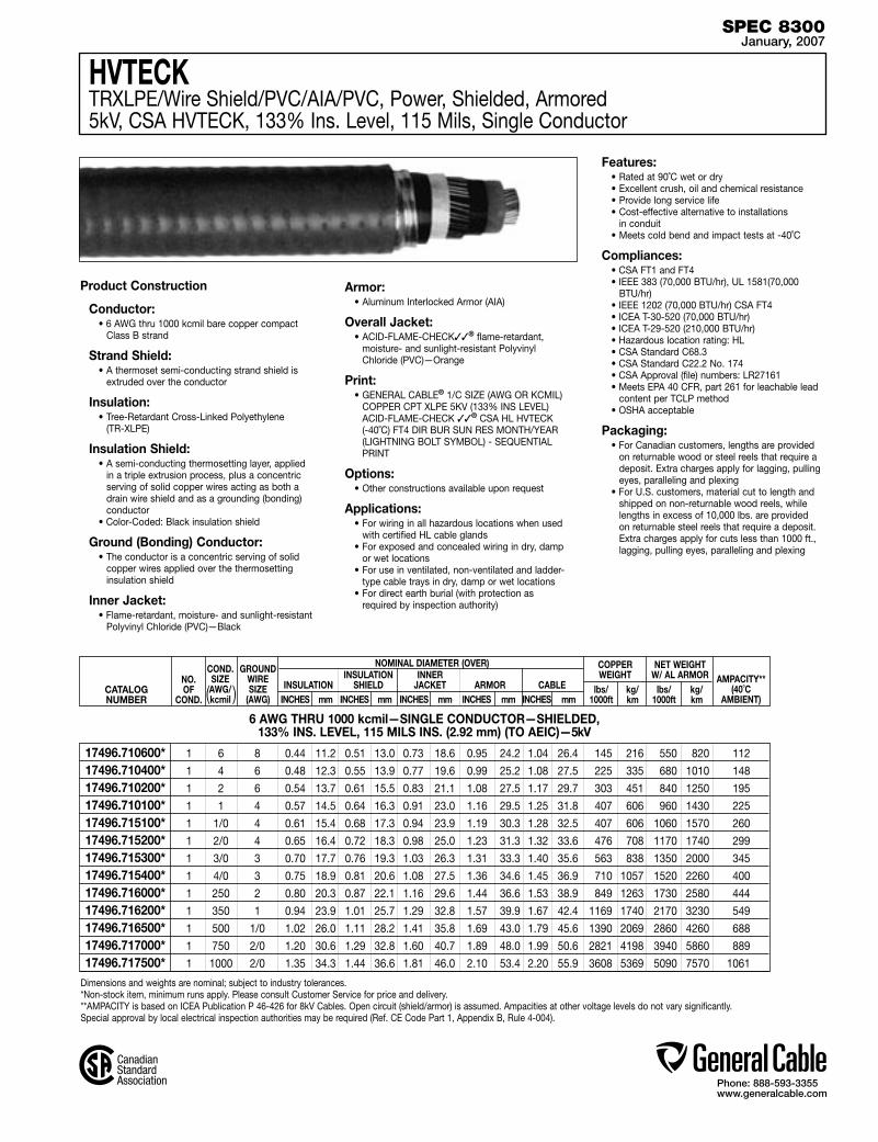
Phone: 888-593-3355www.generalcable.com
Dimensions and weights are nominal; subject to industry tolerances.*Non-stock item, minimum runs apply. Please consult Customer Service for price and delivery.**AMPACITY is based on ICEA Publication P 46-426 for 8kV Cables. Open circuit (shield/armor) is assumed. Ampacities at other voltage levels do not vary significantly. Special approval by local electrical inspection authorities may be required (Ref. CE Code Part 1, Appendix B, Rule 4-004).
CATALOGNUMBER
NO.OF
COND.
NOMINAL DIAMETER (OVER) INSULATION INNER INSULATION SHIELD JACKET ARMOR CABLE AMPACITY**
(40˚C AMBIENT)
COPPERWEIGHT
lbs/ kg/ 1000ft km
NET WEIGHTW/ AL ARMOR lbs/ kg/ 1000ft km INCHES mm INCHES mm INCHES mm INCHES mm INCHES mm
6 AWG THRU 1000 kcmil—SINGLE CONDUCTOR—SHIELDED, 133% INS. LEVEL, 115 MILS INS. (2.92 mm) (TO AEIC)—5kV
Product Construction
Conductor:• 6 AWG thru 1000 kcmil bare copper compact
Class B strand
Strand Shield:• A thermoset semi-conducting strand shield is
extruded over the conductor
Insulation:• Tree-Retardant Cross-Linked Polyethylene
(TR-XLPE)
Insulation Shield:• A semi-conducting thermosetting layer, applied
in a triple extrusion process, plus a concentric serving of solid copper wires acting as both a drain wire shield and as a grounding (bonding) conductor
• Color-Coded: Black insulation shield
Ground (Bonding) Conductor:• The conductor is a concentric serving of solid
copper wires applied over the thermosetting insulation shield
Inner Jacket:• Flame-retardant, moisture- and sunlight-resistant
Polyvinyl Chloride (PVC)—Black
Armor:• Aluminum Interlocked Armor (AIA)
Overall Jacket:• ACID-FLAME-CHECK✓✓® flame-retardant,
moisture- and sunlight-resistant Polyvinyl Chloride (PVC)—Orange
Print:• GENERAL CABLE® 1/C SIZE (AWG OR KCMIL)
COPPER CPT XLPE 5KV (133% INS LEVEL) ACID-FLAME-CHECK ✓✓® CSA HL HVTECK (-40˚C) FT4 DIR BUR SUN RES MONTH/YEAR (LIGHTNING BOLT SYMBOL) - SEQUENTIAL PRINT
Options:• Other constructions available upon request
Applications:• For wiring in all hazardous locations when used
with certified HL cable glands• For exposed and concealed wiring in dry, damp
or wet locations• For use in ventilated, non-ventilated and ladder-
type cable trays in dry, damp or wet locations• For direct earth burial (with protection as
required by inspection authority)
Features:• Rated at 90˚C wet or dry• Excellent crush, oil and chemical resistance• Provide long service life• Cost-effective alternative to installations
in conduit• Meets cold bend and impact tests at -40˚C
Compliances:• CSA FT1 and FT4• IEEE 383 (70,000 BTU/hr), UL 1581(70,000
BTU/hr)• IEEE 1202 (70,000 BTU/hr) CSA FT4• ICEA T-30-520 (70,000 BTU/hr)• ICEA T-29-520 (210,000 BTU/hr)• Hazardous location rating: HL• CSA Standard C68.3• CSA Standard C22.2 No. 174• CSA Approval (file) numbers: LR27161• Meets EPA 40 CFR, part 261 for leachable lead
content per TCLP method• OSHA acceptable
Packaging:• For Canadian customers, lengths are provided
on returnable wood or steel reels that require a deposit. Extra charges apply for lagging, pulling eyes, paralleling and plexing
• For U.S. customers, material cut to length and shipped on non-returnable wood reels, while lengths in excess of 10,000 lbs. are provided on returnable steel reels that require a deposit. Extra charges apply for cuts less than 1000 ft., lagging, pulling eyes, paralleling and plexing
COND.SIZE AWG/kcmil
GROUNDWIRESIZE
(AWG)( )
HVTECKTRXLPE/Wire Shield/PVC/AIA/PVC, Power, Shielded, Armored 5kV, CSA HVTECK, 133% Ins. Level, 115 Mils, Single Conductor
SPEC 8300January, 2007
1 6 8 0.44 11.2 0.51 13.0 0.73 18.6 0.95 24.2 1.04 26.4 145 216 550 820 112
1 4 6 0.48 12.3 0.55 13.9 0.77 19.6 0.99 25.2 1.08 27.5 225 335 680 1010 148
1 2 6 0.54 13.7 0.61 15.5 0.83 21.1 1.08 27.5 1.17 29.7 303 451 840 1250 195
1 1 4 0.57 14.5 0.64 16.3 0.91 23.0 1.16 29.5 1.25 31.8 407 606 960 1430 225
1 1/0 4 0.61 15.4 0.68 17.3 0.94 23.9 1.19 30.3 1.28 32.5 407 606 1060 1570 260
1 2/0 4 0.65 16.4 0.72 18.3 0.98 25.0 1.23 31.3 1.32 33.6 476 708 1170 1740 299
1 3/0 3 0.70 17.7 0.76 19.3 1.03 26.3 1.31 33.3 1.40 35.6 563 838 1350 2000 345
1 4/0 3 0.75 18.9 0.81 20.6 1.08 27.5 1.36 34.6 1.45 36.9 710 1057 1520 2260 400
1 250 2 0.80 20.3 0.87 22.1 1.16 29.6 1.44 36.6 1.53 38.9 849 1263 1730 2580 444
1 350 1 0.94 23.9 1.01 25.7 1.29 32.8 1.57 39.9 1.67 42.4 1169 1740 2170 3230 549
1 500 1/0 1.02 26.0 1.11 28.2 1.41 35.8 1.69 43.0 1.79 45.6 1390 2069 2860 4260 688
1 750 2/0 1.20 30.6 1.29 32.8 1.60 40.7 1.89 48.0 1.99 50.6 2821 4198 3940 5860 889
1 1000 2/0 1.35 34.3 1.44 36.6 1.81 46.0 2.10 53.4 2.20 55.9 3608 5369 5090 7570 1061
17496.710600* 17496.710400* 17496.710200* 17496.710100*17496.715100* 17496.715200* 17496.715300* 17496.715400*17496.716000* 17496.716200*17496.716500* 17496.717000* 17496.717500*
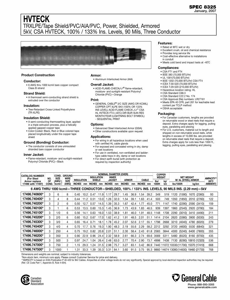
Phone: 888-593-3355www.generalcable.com
Dimensions and weights are nominal; subject to industry tolerances.*Non-stock item, minimum runs apply. Please consult Customer Service for price and delivery.**AMPACITY is based on ICEA Publication P 46-426 for 8kV Cables. Ampacities at other voltage levels do not vary significantly. Special approval by local electrical inspection authorities may be required (Ref. CE Code Part 1, Appendix B, Rule 4-004).
CATALOG NUMBER(For Steel
Armor replace17496 with 17497)
NO.OF
COND.
NOMINAL DIAMETER (OVER) INSULATION INNER INSULATION SHIELD JACKET ARMOR CABLE AMPACITY**
(40˚C AMBIENT)
COPPERWEIGHT
lbs/ kg/ 1000ft km
NET WEIGHTW/ AL (STEEL) ARMOR
lbs/1000ft kg/km INCHES mm INCHES mm INCHES mm INCHES mm INCHES mm
6 AWG THRU 1000 kcmil—THREE CONDUCTOR—SHIELDED, 100% / 133% INS. LEVELS, 90 MILS INS. (2.29 mm)—5kV
Product Construction
Conductor:• 6 AWG thru 1000 kcmil bare copper compact
Class B strand
Strand Shield:• A thermoset semi-conducting strand shield is
extruded over the conductor
Insulation:• Tree-Retardant Cross-Linked Polyethylene
(TR-XLPE)
Insulation Shield:• A semi-conducting thermosetting layer, applied
in a triple extrusion process, plus a helically applied gapped copper tape
• Color-Coded: Black, Red or Blue colored tape placed longitudinally under the copper tape shield
Ground (Bonding) Conductor:• The conductor consists of one uninsulated
stranded bare copper conductor
Inner Jacket:• Flame-retardant, moisture- and sunlight-resistant
Polyvinyl Chloride (PVC)—Black
Armor:• Aluminum Interlocked Armor (AIA)
Overall Jacket:• ACID-FLAME-CHECK✓✓® flame-retardant,
moisture- and sunlight-resistant Polyvinyl Chloride (PVC)—Orange
Print:• GENERAL CABLE® 3/C SIZE (AWG OR KCMIL)
COPPER CPT XLPE 5KV (100% OR 133% INS LEVEL) ACID-FLAME-CHECK ✓✓® CSA HL HVTECK FT4 (-40˚C) DIR BUR SUN RES MONTH/YEAR (LIGHTNING BOLT SYMBOL) - SEQUENTIAL PRINT
Options:• Galvanized Steel Interlocked Armor (GSIA)• Other constructions available upon request
Applications:• For wiring in all hazardous locations when used
with certified HL cable glands• For exposed and concealed wiring in dry, damp
or wet locations• For use in ventilated, non-ventilated and ladder-
type cable trays in dry, damp or wet locations• For direct earth burial (with protection as
required by inspection authority)
Features:• Rated at 90˚C wet or dry• Excellent crush, oil and chemical resistance• Provides long service life• Cost-effective alternative to installations
in conduit• Meets cold bend and impact tests at -40˚C
Compliances:• CSA FT1 and FT4• IEEE 383 (70,000 BTU/hr)• UL 1581(70,000 BTU/hr)• IEEE 1202 (70,000 BTU/hr) CSA FT4• ICEA T-30-520 (70,000 BTU/hr)• ICEA T-29-520 (210,000 BTU/hr)• Hazardous location rating: HL• CSA Standard C68.3• CSA Standard C22.2 No. 174• CSA Approval (file) numbers: LR27161• Meets EPA 40 CFR, part 261 for leachable lead
content per TCLP method• OSHA acceptable
Packaging:• For Canadian customers, lengths are provided
on returnable wood or steel reels that require a deposit. Extra charges apply for lagging, pulling eyes, paralleling and plexing
• For U.S. customers, material cut to length and shipped on non-returnable wood reels, while lengths in excess of 10,000 lbs. are provided on returnable steel reels that require a deposit. Extra charges apply for cuts less than 1000 ft., lagging, pulling eyes, paralleling and plexing
HVTECKTRXLPE/Tape Shield/PVC/AIA/PVC, Power, Shielded, Armored 5kV, CSA HVTECK, 100% / 133% Ins. Levels, 90 Mils, Three Conductor
COND.SIZE AWG/kcmil
GROUNDWIRESIZE
(AWG)( )
SPEC 8325January, 2007
3 6 8 0.40 10.2 0.47 11.9 1.17 29.7 1.45 36.9 1.54 39.2 349 519 1120 (1590) 1670 (2360) 93
3 4 8 0.44 11.2 0.51 13.0 1.26 32.0 1.54 39.1 1.63 41.4 503 749 1350 (1850) 2010 (2760) 122
3 2 6 0.50 12.7 0.57 14.5 1.39 35.3 1.67 42.4 1.77 45.0 771 1147 1740 (2290) 2590 (3410) 159
3 1 6 0.53 13.5 0.60 15.3 1.45 36.9 1.73 43.9 1.83 46.5 939 1397 1960 (2540) 2920 (3780) 184
3 1/0 6 0.56 14.1 0.63 16.0 1.53 38.9 1.81 46.0 1.91 48.5 1148 1708 2290 (3010) 3410 (4490) 211
3 2/0 6 0.60 15.2 0.67 17.0 1.62 41.2 1.91 48.5 2.01 51.1 1414 2104 2620 (3380) 3900 (5030) 243
3 3/0 4 0.65 16.4 0.71 18.1 1.78 45.2 2.07 52.6 2.17 55.1 1798 2668 3210 (4040) 4780 (6020) 279
3 4/0 4 0.70 17.7 0.76 19.3 1.90 48.3 2.19 55.6 2.29 58.2 2212 3292 3720 (4600) 5530 (6840) 321
3 250 4 0.75 19.2 0.82 20.8 2.01 51.1 2.30 58.4 2.43 61.8 2583 3844 4300 (5240) 6400 (7800) 355
3 350 3 0.90 22.9 0.96 24.4 2.32 58.9 2.61 66.3 2.74 69.6 3569 5311 5480 (6520) 8160 (9700) 435
3 500 3 0.97 24.7 1.04 26.4 2.48 63.0 2.77 70.4 2.90 73.7 4998 7438 7130 (8280) 10610 (12320) 536
3 750 2 1.15 29.3 1.24 31.5 2.98 75.7 3.27 83.1 3.42 86.9 7440 11072 10330 (11700) 15370 (17410) 668
3 1000 1 1.31 33.3 1.39 35.3 3.31 84.1 3.60 91.5 3.75 95.3 9860 14674 13080 (14600) 19460 (21730) 768
17496.740600* 17496.740400* 17496.740200* 17496.740100*17496.745100* 17496.745200* 17496.745300* 17496.745400*17496.746000* 17496.746200* 17496.746500* 17496.747000* 17496.747500*
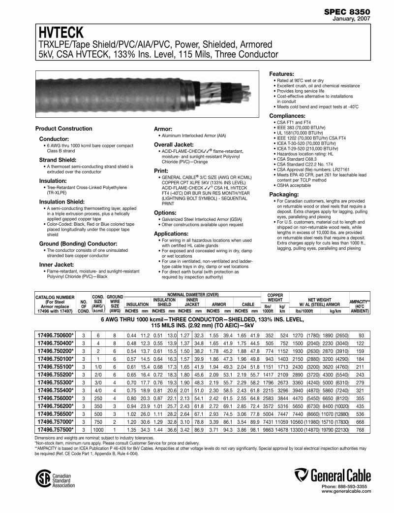
Phone: 888-593-3355www.generalcable.com
HVTECKTRXLPE/Tape Shield/PVC/AIA/PVC, Power, Shielded, Armored 5kV, CSA HVTECK, 133% Ins. Level, 115 Mils, Three Conductor
Dimensions and weights are nominal; subject to industry tolerances.*Non-stock item, minimum runs apply. Please consult Customer Service for price and delivery.**AMPACITY is based on ICEA Publication P 46-426 for 8kV Cables. Ampacities at other voltage levels do not vary significantly. Special approval by local electrical inspection authorities may be required (Ref. CE Code Part 1, Appendix B, Rule 4-004).
CATALOG NUMBER(For Steel
Armor replace17496 with 17497)
NO.OF
COND.
NOMINAL DIAMETER (OVER) INSULATION INNER INSULATION SHIELD JACKET ARMOR CABLE AMPACITY**
(40˚C AMBIENT)
COPPERWEIGHT
lbs/ kg/ 1000ft km
NET WEIGHTW/ AL (STEEL) ARMOR
lbs/1000ft kg/km INCHES mm INCHES mm INCHES mm INCHES mm INCHES mm
6 AWG THRU 1000 kcmil—THREE CONDUCTOR—SHIELDED, 133% INS. LEVEL, 115 MILS INS. (2.92 mm) (TO AEIC)—5kV
Product Construction
Conductor:• 6 AWG thru 1000 kcmil bare copper compact
Class B strand
Strand Shield:• A thermoset semi-conducting strand shield is
extruded over the conductor
Insulation:• Tree-Retardant Cross-Linked Polyethylene
(TR-XLPE)
Insulation Shield:• A semi-conducting thermosetting layer, applied
in a triple extrusion process, plus a helically applied gapped copper tape
• Color-Coded: Black, Red or Blue colored tape placed longitudinally under the copper tape shield
Ground (Bonding) Conductor:• The conductor consists of one uninsulated
stranded bare copper conductor
Inner Jacket:• Flame-retardant, moisture- and sunlight-resistant
Polyvinyl Chloride (PVC)—Black
Armor:• Aluminum Interlocked Armor (AIA)
Overall Jacket:• ACID-FLAME-CHECK✓✓® flame-retardant,
moisture- and sunlight-resistant Polyvinyl Chloride (PVC)—Orange
Print:• GENERAL CABLE® 3/C SIZE (AWG OR KCMIL)
COPPER CPT XLPE 5KV (133% INS LEVEL) ACID-FLAME-CHECK ✓✓® CSA HL HVTECK FT4 (-40˚C) DIR BUR SUN RES MONTH/YEAR (LIGHTNING BOLT SYMBOL) - SEQUENTIAL PRINT
Options:• Galvanized Steel Interlocked Armor (GSIA)• Other constructions available upon request
Applications:• For wiring in all hazardous locations when used
with certified HL cable glands• For exposed and concealed wiring in dry, damp
or wet locations• For use in ventilated, non-ventilated and ladder-
type cable trays in dry, damp or wet locations• For direct earth burial (with protection as
required by inspection authority)
Features:• Rated at 90˚C wet or dry• Excellent crush, oil and chemical resistance• Provides long service life• Cost-effective alternative to installations
in conduit• Meets cold bend and impact tests at -40˚C
Compliances:• CSA FT1 and FT4• IEEE 383 (70,000 BTU/hr)• UL 1581(70,000 BTU/hr)• IEEE 1202 (70,000 BTU/hr) CSA FT4• ICEA T-30-520 (70,000 BTU/hr)• ICEA T-29-520 (210,000 BTU/hr)• Hazardous location rating: HL• CSA Standard C68.3• CSA Standard C22.2 No. 174• CSA Approval (file) numbers: LR27161• Meets EPA 40 CFR, part 261 for leachable lead
content per TCLP method• OSHA acceptable
Packaging:• For Canadian customers, lengths are provided
on returnable wood or steel reels that require a deposit. Extra charges apply for lagging, pulling eyes, paralleling and plexing
• For U.S. customers, material cut to length and shipped on non-returnable wood reels, while lengths in excess of 10,000 lbs. are provided on returnable steel reels that require a deposit. Extra charges apply for cuts less than 1000 ft., lagging, pulling eyes, paralleling and plexing
COND.SIZE AWG/kcmil
GROUNDWIRESIZE
(AWG)( )
SPEC 8350January, 2007
3 6 8 0.44 11.2 0.51 13.0 1.27 32.3 1.55 39.4 1.65 41.9 352 524 1270 (1780) 1890 (2650) 93
3 4 8 0.48 12.3 0.55 13.9 1.37 34.8 1.65 41.9 1.75 44.5 505 752 1500 (2040) 2230 (3040) 122
3 2 6 0.54 13.7 0.61 15.5 1.50 38.2 1.78 45.2 1.88 47.8 774 1152 1930 (2630) 2870 (3910) 159
3 1 6 0.57 14.5 0.64 16.3 1.57 39.9 1.86 47.3 1.96 49.8 943 1403 2150 (2880) 3200 (4290) 184
3 1/0 6 0.61 15.4 0.68 17.3 1.65 41.9 1.94 49.3 2.04 51.8 1151 1713 2430 (3200) 3620 (4760) 211
3 2/0 6 0.65 16.4 0.72 18.3 1.80 45.6 2.09 53.1 2.19 55.7 1417 2109 2890 (3720) 4300 (5540) 243
3 3/0 4 0.70 17.7 0.76 19.3 1.90 48.3 2.19 55.7 2.29 58.2 1796 2673 3360 (4240) 5000 (6310) 279
3 4/0 4 0.75 18.9 0.81 20.6 2.01 51.0 2.30 58.5 2.43 61.8 2215 3296 3940 (4870) 5860 (7240) 321
3 250 4 0.80 20.3 0.87 22.1 2.13 54.1 2.42 61.5 2.55 64.8 2583 3844 4470 (5450) 6650 (8120) 355
3 350 3 0.94 23.9 1.01 25.7 2.43 61.8 2.72 69.1 2.85 72.4 3572 5316 5650 (6730) 8400 (10020) 435
3 500 3 1.02 26.0 1.11 28.2 2.64 67.1 2.93 74.5 3.06 77.8 5004 7447 7440 (8660) 11070 (12880) 536
3 750 2 1.20 30.6 1.29 32.8 3.10 78.8 3.39 86.1 3.54 89.9 7431 11059 10560 (11980) 15710 (17830) 668
3 1000 1 1.35 34.3 1.44 36.6 3.42 86.9 3.71 94.3 3.86 98.1 9863 14678 13300 (14870) 19790 (22130) 768
17496.750600* 17496.750400* 17496.750200* 17496.750100*17496.755100* 17496.755200* 17496.755300* 17496.755400*17496.756000* 17496.756200* 17496.756500* 17496.757000* 17496.757500*

Phone: 888-593-3355www.generalcable.com
Dimensions and weights are nominal; subject to industry tolerances.*Non-stock item, minimum runs apply. Please consult Customer Service for price and delivery.**AMPACITY is based on ICEA Publication P 46-426 for 15kV Cables. Open circuit (shield/armor) is assumed. Ampacities at other voltage levels do not vary significantly. Special approval by local electrical inspection authorities may be required (Ref. CE Code Part 1, Appendix B, Rule 4-004).
CATALOGNUMBER
NO.OF
COND.
NOMINAL DIAMETER (OVER) INSULATION INNER INSULATION SHIELD JACKET ARMOR CABLE AMPACITY**
(40˚C AMBIENT)
COPPERWEIGHT
lbs/ kg/ 1000ft km
NET WEIGHTW/ AL ARMOR lbs/ kg/ 1000ft km INCHES mm INCHES mm INCHES mm INCHES mm INCHES mm
2 AWG THRU 1000 kcmil—SINGLE CONDUCTOR—100% INS. LEVEL, 175 MILS INS. (4.45 mm)—15kV
Product Construction
Conductor:• 2 AWG thru 1000 kcmil bare copper compact
Class B strand
Strand Shield:• A thermoset semi-conducting strand shield is
extruded over the conductor
Insulation:• Tree-Retardant Cross-Linked Polyethylene
(TR-XLPE)
Insulation Shield:• A semi-conducting thermosetting layer, applied
in a triple extrusion process, plus a concentric serving of solid copper wires acting as both a drain wire shield and as a grounding (bonding) conductor
• Color-Coded: Black insulation shield
Ground (Bonding) Conductor:• The conductor is a concentric serving of solid
copper wires applied over the thermosetting insulation shield
Inner Jacket:• Flame-retardant, moisture- and sunlight-resistant
Polyvinyl Chloride (PVC)—Black
Armor:• Aluminum Interlocked Armor (AIA)
Overall Jacket:• ACID-FLAME-CHECK✓✓® Flame-retardant,
moisture- and sunlight-resistant Polyvinyl Chloride (PVC)—Red
Print:• GENERAL CABLE® 1/C SIZE (AWG OR KCMIL)
COPPER CPT XLPE 15KV (100% INS LEVEL) ACID-FLAME-CHECK ✓✓® CSA HL HVTECK FT4 (-40˚C) DIR BUR SUN RES MONTH/YEAR (LIGHTNING BOLT SYMBOL)—SEQUENTIAL PRINT
Options:• Other constructions available upon request
Applications:• For wiring in all hazardous locations when used
with certified HL cable glands• For exposed and concealed wiring in dry, damp
or wet locations• For use in ventilated, non-ventilated and ladder-
type cable trays in dry, damp or wet locations• For direct earth burial (with protection as
required by inspection authority)
Features:• Rated at 90˚C wet or dry• Excellent crush, oil and chemical resistance• Provides long service life• Cost-effective alternative to installations
in conduit• Meets cold bend and impact tests at -40˚C
Compliances:• CSA FT1 and FT4• IEEE 383 (70,000 BTU/hr)• UL 1581(70,000 BTU/hr)• IEEE 1202 (70,000 BTU/hr) CSA FT4• ICEA T-30-520 (70,000 BTU/hr)• ICEA T-29-520 (210,000 BTU/hr)• Hazardous location rating: HL• CSA Standard C68.3• CSA Standard C22.2 No. 174• CSA Approval (file) numbers: LR27161• Meets EPA 40 CFR, part 261 for leachable lead
content per TCLP method• OSHA acceptable
Packaging:• For Canadian customers, lengths are provided
on returnable wood or steel reels that require a deposit. Extra charges apply for lagging, pulling eyes, paralleling and plexing
• For U.S. customers, material cut to length and shipped on non-returnable wood reels, while lengths in excess of 10,000 lbs. are provided on returnable steel reels that require a deposit. Extra charges apply for cuts less than 1000 ft., lagging, pulling eyes, paralleling and plexing
HVTECKTRXLPE/Wire Shield/PVC/AIA/PVC, Power, Shielded, Armored 15kV, CSA HVTECK, 100% Ins. Level, 175 Mils, Single Conductor
COND.SIZE AWG/kcmil
GROUNDWIRESIZE
(AWG)( )
SPEC 8375January, 2007
1 2 6 0.66 16.7 0.73 18.6 0.99 25.3 1.24 31.5 1.33 33.8 304 482 950 1420 195
1 1 4 0.69 17.5 0.76 19.3 1.03 26.1 1.28 32.5 1.37 34.8 408 607 1080 1600 225
1 1/0 4 0.73 18.5 0.80 20.3 1.06 27.0 1.31 33.3 1.40 35.6 477 710 1170 1750 259
1 2/0 4 0.77 19.5 0.84 21.3 1.10 27.9 1.35 34.3 1.44 36.6 564 839 1290 1920 298
1 3/0 3 0.82 20.8 0.88 22.4 1.15 29.2 1.40 35.6 1.49 37.9 711 1058 1470 2190 343
1 4/0 3 0.87 22.0 0.94 23.9 1.21 30.6 1.46 37.1 1.55 39.4 850 1265 1640 2450 397
1 250 2 0.93 23.5 0.99 25.2 1.28 32.5 1.53 38.9 1.63 41.4 1015 1511 1900 2830 440
1 350 1 1.07 27.2 1.15 29.2 1.43 36.3 1.71 43.5 1.81 46.0 1391 2070 2370 3530 543
1 500 1/0 1.14 29.0 1.23 31.2 1.54 39.1 1.83 46.5 1.93 49.1 1930 2872 3080 4590 678
1 750 2/0 1.32 33.6 1.41 35.9 1.78 45.2 2.07 52.6 2.17 55.2 2822 4200 4240 6320 872
1 1000 2/0 1.48 37.6 1.57 39.9 1.93 49.0 2.22 56.4 2.32 59.0 3609 5371 5280 7860 1040
17496.810200* 17496.810100* 17496.815100* 17496.815200*17496.815300* 17496.815400* 17496.816000*17496.816200* 17496.816500*17496.817000* 17496.817500*

Phone: 888-593-3355www.generalcable.com
HVTECKTRXLPE/Wire Shield/PVC/AIA/PVC, Power, Shielded, Armored 15kV, CSA HVTECK, 133% Ins. Level, 220 Mils, Single Conductor
Dimensions and weights are nominal; subject to industry tolerances.*Non-stock item, minimum runs apply. Please consult Customer Service for price and delivery.**AMPACITY is based on ICEA Publication P 46-426 for 15kV Cables. Open circuit (shield/armor) is assumed. Ampacities at other voltage levels do not vary significantly. Special approval by local electrical inspection authorities may be required (Ref. CE Code Part 1, Appendix B, Rule 4-004).
CATALOGNUMBER
NO.OF
COND.
NOMINAL DIAMETER (OVER) INSULATION INNER INSULATION SHIELD JACKET ARMOR CABLE AMPACITY**
(40˚C AMBIENT)
COPPERWEIGHT
lbs/ kg/ 1000ft km
NET WEIGHTW/ AL ARMOR lbs/ kg/ 1000ft km INCHES mm INCHES mm INCHES mm INCHES mm INCHES mm
2 AWG THRU 1000 kcmil—SINGLE CONDUCTOR—133% INS. LEVEL, 220 MILS INS. (5.59 mm)—15kV
Product Construction
Conductor:• 2 AWG thru 1000 kcmil bare copper compact
Class B strand
Strand Shield:• A thermoset semi-conducting strand shield is
extruded over the conductor
Insulation:• Tree-Retardant Cross-Linked Polyethylene
(TR-XLPE)
Insulation Shield:• A semi-conducting thermosetting layer, applied
in a triple extrusion process, plus a concentric serving of solid copper wires acting as both a drain wire shield and as a grounding (bonding) conductor
• Color-Coded: Black insulation shield
Ground (Bonding) Conductor:• The conductor is a concentric serving of solid
copper wires applied over the thermosetting insulation shield
Inner Jacket:• Flame-retardant, moisture- and sunlight-resistant
Polyvinyl Chloride (PVC)—Black
Armor:• Aluminum Interlocked Armor (AIA)
Overall Jacket:• ACID-FLAME-CHECK✓✓® flame-retardant,
moisture- and sunlight-resistant Polyvinyl Chloride (PVC)—Red
Print:• GENERAL CABLE® 1/C SIZE (AWG OR KCMIL)
COPPER CPT XLPE 15KV (133% INS LEVEL) ACID-FLAME-CHECK ✓✓® CSA HL HVTECK FT4 (-40˚C) DIR BUR SUN RES MONTH/YEAR (LIGHTNING BOLT SYMBOL) - SEQUENTIAL PRINT
Options:• Other constructions available upon request
Applications:• For wiring in all hazardous locations when used
with certified HL cable glands• For exposed and concealed wiring in dry, damp
or wet locations• For use in ventilated, non-ventilated and ladder-
type cable trays in dry, damp or wet locations• For direct earth burial (with protection as
required by inspection authority)
Features:• Rated at 90˚C wet or dry• Excellent crush, oil and chemical resistance• Provides long service life• Cost-effective alternative to installations
in conduit• Meets cold bend and impact tests at -40˚C
Compliances:• CSA FT1 and FT4• IEEE 383 (70,000 BTU/hr)• UL 1581(70,000 BTU/hr)• IEEE 1202 (70,000 BTU/hr) CSA FT4• ICEA T-30-520 (70,000 BTU/hr)• ICEA T-29-520 (210,000 BTU/hr)• Hazardous location rating: HL• CSA Standard C68.3• CSA Standard C22.2 No. 174• CSA Approval (file) numbers: LR27161• Meets EPA 40 CFR, part 261 for leachable lead
content per TCLP method• OSHA acceptable
Packaging:• For Canadian customers, lengths are provided
on returnable wood or steel reels that require a deposit. Extra charges apply for lagging, pulling eyes, paralleling and plexing
• For U.S. customers, material cut to length and shipped on non-returnable wood reels, while lengths in excess of 10,000 lbs. are provided on returnable steel reels that require a deposit. Extra charges apply for cuts less than 1000 ft., lagging, pulling eyes, paralleling and plexing
COND.SIZE AWG/kcmil
GROUNDWIRESIZE
(AWG)( )
SPEC 8400January, 2007
1 2 6 0.76 19.3 0.83 21.1 1.09 27.7 1.34 34.1 1.43 36.4 305 454 1028 1530 19
1 1 4 0.79 20.1 0.86 21.9 1.12 28.4 1.37 34.8 1.46 37.1 410 610 1170 1740 225
1 1/0 4 0.83 21.1 0.89 22.6 1.16 29.4 1.41 35.8 1.50 38.1 479 713 1270 1890 259
1 2/0 4 0.86 21.8 0.93 23.6 1.20 30.4 1.45 36.9 1.54 39.2 566 842 1390 2060 298
1 3/0 3 0.91 23.0 0.98 24.9 1.25 31.7 1.50 38.1 1.59 40.4 714 1063 1570 2340 343
1 4/0 3 0.96 24.3 1.03 26.2 1.30 33.0 1.58 40.2 1.68 42.7 854 1271 1780 2650 397
1 250 2 1.02 25.8 1.08 27.5 1.38 35.0 1.66 42.2 1.76 44.7 1020 1518 2010 2990 440
1 350 1 1.12 28.3 1.20 30.5 1.50 38.0 1.78 45.2 1.88 47.8 1396 2078 2490 3700 543
1 500 1/0 1.24 31.5 1.32 33.6 1.65 41.8 1.94 49.3 2.04 51.9 2828 4209 3220 4790 678
1 750 2/0 1.42 36.0 1.51 38.3 1.89 48.0 2.18 55.4 2.28 57.9 3616 5381 4390 6530 872
1 1000 2/0 1.57 39.9 1.68 42.6 2.05 52.1 2.34 59.5 2.48 63.0 8260 5550 5550 8260 1040
17496.216500* 17496.820100* 17496.825100* 17496.825200* 17496.825300*17496.825400* 17496.826000* 17496.826200*17496.826500 17496.82700017496.827500*

Phone: 888-593-3355www.generalcable.com
HVTECKTRXLPE/Tape Shield/PVC/AIA/PVC, Power, Shielded, Armored 15kV, CSA HVTECK, 100% Ins. Level, 175 Mils, Three Conductor
Dimensions and weights are nominal; subject to industry tolerances.*Non-stock item, minimum runs apply. Please consult Customer Service for price and delivery.**AMPACITY is based on ICEA Publication P 46-426 for 15kV Cables. Ampacities at other voltage levels do not vary significantly. Special approval by local electrical inspection authorities may be required (Ref. CE Code Part 1, Appendix B, Rule 4-004).
CATALOGNUMBER
(For steel armor replace 17496 with 17497)
NO.OF
COND.
NOMINAL DIAMETER (OVER) INSULATION INNER INSULATION SHIELD JACKET ARMOR CABLE AMPACITY**
(40˚C AMBIENT)
COPPERWEIGHT
lbs/ kg/ 1000ft km
NET WEIGHTW/ AL (STEEL) ARMOR
lbs/1000ft kg/km INCHES mm INCHES mm INCHES mm INCHES mm INCHES mm
2 AWG THRU 1000 kcmil—THREE CONDUCTOR—100% INS. LEVEL, 175 MILS INS. (4.45 mm)—15kV
Product Construction
Conductor:• 2 AWG thru 1000 kcmil bare copper compact
Class B strand
Strand Shield:• A thermoset semi-conducting strand shield is
extruded over the conductor
Insulation:• Tree-Retardant Cross-Linked Polyethylene
(TR-XLPE)
Insulation Shield:• This consists of a semi-conducting
thermosetting layer, applied in a triple extrusion process, plus a helically applied gapped copper tape
• Color-Coded: Black, Red or Blue colored tape placed longitudinally under the copper tape shield
Ground (Bonding) Conductor:• The conductor consists of one uninsulated
stranded bare copper conductor
Inner Jacket:• Flame-retardant, moisture- and sunlight-resistant
Polyvinyl Chloride (PVC)—Black
Armor:• Aluminum Interlocked Armor (AIA)
Overall Jacket:• ACID-FLAME-CHECK✓✓® flame-retardant,
moisture- and sunlight-resistant Polyvinyl Chloride (PVC)—Red
Print:• GENERAL CABLE® 3/C SIZE (AWG OR KCMIL)
COPPER CPT XLPE 15KV (100% INS LEVEL) ACID-FLAME-CHECK ✓✓® CSA HL HVTECK FT4 (-40˚C) DIR BUR SUN RES MONTH/YEAR (LIGHTNING BOLT SYMBOL) - SEQUENTIAL PRINT
Options:• Galvanized Steel Interlocked Armor (GSIA)• Other constructions available upon request
Applications:• For wiring in all hazardous locations when used
with certified HL cable glands• For exposed and concealed wiring in dry, damp
or wet locations• For use in ventilated, non-ventilated and ladder-
type cable trays in dry, damp or wet locations• For direct earth burial (with protection as
required by inspection authority)
Features:• Rated at 90˚C wet or dry• Excellent crush, oil and chemical resistance• Provides long service life• Cost-effective alternative to installations
in conduit• Meets cold bend and impact tests at -40˚C
Compliances:• CSA FT1 and FT4• IEEE 383 (70,000 BTU/hr)• UL 1581(70,000 BTU/hr)• IEEE 1202 (70,000 BTU/hr) CSA FT4• ICEA T-30-520 (70,000 BTU/hr)• ICEA T-29-520 (210,000 BTU/hr)• Hazardous location rating: HL• CSA Standard C68.3• CSA Standard C22.2 No. 174• CSA Approval (file) numbers: LR27161• Meets EPA 40 CFR, part 261 for leachable lead
content per TCLP method• OSHA acceptable
Packaging:• For Canadian customers, lengths are provided
on returnable wood or steel reels that require a deposit. Extra charges apply for lagging, pulling eyes, paralleling and plexing
• For U.S. customers, material cut to length and shipped on non-returnable wood reels, while lengths in excess of 10,000 lbs. are provided on returnable steel reels that require a deposit. Extra charges apply for cuts less than 1000 ft., lagging, pulling eyes, paralleling and plexing
COND.SIZE AWG/kcmil
GROUNDWIRESIZE
(AWG)( )
SPEC 8425January, 2007
3 2 6 0.66 16.7 0.73 18.6 1.82 46.3 2.11 53.6 2.21 56.2 787 1171 2370 (3220) 3530 (4790) 164
3 1 6 0.69 17.5 0.76 19.3 1.89 48.0 2.18 55.4 2.27 57.7 955 1421 2620 (3490) 3890 (5190) 187
3 1/0 6 0.73 18.5 0.79 20.1 1.97 50.0 2.26 57.4 2.35 59.7 1163 1731 2900 (3810) 4320 (5670) 215
3 2/0 6 0.77 19.5 0.84 21.3 2.06 52.3 2.34 59.5 2.46 62.5 1429 2127 3330 (4280) 4960 (6370) 246
3 3/0 4 0.82 20.8 0.88 22.4 2.16 54.9 2.44 62.0 2.57 65.3 1812 2697 3840 (4840) 5720 (7200) 283
3 4/0 4 0.87 22.0 0.93 23.7 2.27 57.7 2.56 65.1 2.68 68.1 2228 3316 4360 (5410) 6490 (8050) 325
3 250 4 0.93 23.5 0.99 25.2 2.38 60.5 2.68 68.1 2.79 70.9 2598 3866 4880 (5990) 7260 (8910) 359
3 350 3 1.06 26.9 1.15 29.2 2.73 69.4 3.02 76.7 3.14 79.8 3587 5338 6210 (7430) 9240 (11060) 438
3 500 3 1.14 29.0 1.23 31.2 2.97 75.5 3.26 82.8 3.40 86.4 5013 7460 8549 (9550) 12721 (14200) 536
3 750 2 1.32 33.6 1.41 35.9 3.35 85.1 3.64 92.5 3.77 95.8 7446 1108 11100 (12640) 16520 (18810) 669
3 1000 1 1.47 37.4 1.56 39.6 3.72 94.5 3.97 100.8 4.17 105.9 9376 13953 13890 (15580) 20670 (23180) 770
17496.030200* 17496.830100* 17496.835100* 17496.835200*17496.835300* 17496.835400* 17496.836000* 17496.836200*17496.536500* 17496.837000*17496.837500*

Phone: 888-593-3355www.generalcable.com
HVTECKTRXLPE/Tape Shield/PVC/AIA/PVC, Power, Shielded, Armored 15kV, CSA HVTECK, 133% Ins. Level, 220 Mils, Three Conductor
Dimensions and weights are nominal; subject to industry tolerances.*Non-stock item, minimum runs apply. Please consult Customer Service for price and delivery.**AMPACITY is based on ICEA Publication P 46-426 for 15kV Cables. Ampacities at other voltage levels do not vary significantly. Special approval by local electrical inspection authorities may be required (Ref. CE Code Part 1, Appendix B, Rule 4-004).
CATALOG NUMBER(For Steel
Armor replace17496 with 17497)
NO.OF
COND.
NOMINAL DIAMETER (OVER) INSULATION INNER INSULATION SHIELD JACKET ARMOR CABLE AMPACITY**
(40˚C AMBIENT)
COPPERWEIGHT
lbs/ kg/ 1000ft km
NET WEIGHTW/ AL (STEEL) ARMOR
lbs/1000ft kg/km INCHES mm INCHES mm INCHES mm INCHES mm INCHES mm
2 AWG THRU 750 kcmil—THREE CONDUCTOR—133% INS. LEVEL, 220 MILS INS. (5.59 mm)—15kV
Product Construction
Conductor:• 2 AWG thru 750 kcmil bare copper compact
Class B strand
Strand Shield:• A thermoset semi-conducting strand shield is
extruded over the conductor
Insulation:• Tree-Retardant Cross-Linked Polyethylene
(TR-XLPE)
Insulation Shield:• This consists of a semi-conducting
thermosetting layer, applied in a triple extrusion process, plus a helically applied gapped copper tape
• Color-Coded: Black, Red or Blue colored tape placed longitudinally under the copper tape shield
Ground (Bonding) Conductor:• The conductor consists of one uninsulated
stranded bare copper conductor
Inner Jacket:• Flame-retardant, moisture- and sunlight-resistant
Polyvinyl Chloride (PVC)—Black
Armor:• Aluminum Interlocked Armor (AIA)
Overall Jacket:• ACID-FLAME-CHECK✓✓® flame-retardant,
moisture- and sunlight-resistant Polyvinyl Chloride (PVC)—Red
Print:• GENERAL CABLE® 3/C SIZE (AWG OR KCMIL)
COPPER CPT XLPE 15KV (133% INS LEVEL) ACID-FLAME-CHECK ✓✓® CSA HL HVTECK FT4 (-40˚C) DIR BUR SUN RES MONTH/YEAR (LIGHTNING BOLT SYMBOL) - SEQUENTIAL PRINT
Options:• Galvanized Steel Interlocked Armor (GSIA)• Other options available upon request
Applications:• For wiring in all hazardous locations when used
with certified HL cable glands• For exposed and concealed wiring in dry, damp
or wet locations• For use in ventilated, non-ventilated and ladder-
type cable trays in dry, damp or wet locations• For direct earth burial (with protection as
required by inspection authority)
Features:• Rated at 90˚C wet or dry• Excellent crush, oil and chemical resistance• Provides long service life• Cost-effective alternative to installations
in conduit• Meets cold bend and impact tests at -40˚C
Compliances:• CSA FT1 and FT4• IEEE 383 (70,000 BTU/hr)• UL 1581(70,000 BTU/hr)• IEEE 1202 (70,000 BTU/hr) CSA FT4• ICEA T-30-520 (70,000 BTU/hr)• ICEA T-29-520 (210,000 BTU/hr)• Hazardous location rating: HL• CSA Standard C68.3• CSA Standard C22.2 No. 174• CSA Approval (file) numbers: LR27161• Meets EPA 40 CFR, part 261 for leachable lead
content per TCLP method• OSHA acceptable
Packaging:• For Canadian customers, lengths are provided
on returnable wood or steel reels that require a deposit. Extra charges apply for lagging, pulling eyes, paralleling and plexing
• For U.S. customers, material cut to length and shipped on non-returnable wood reels, while lengths in excess of 10,000 lbs. are provided on returnable steel reels that require a deposit. Extra charges apply for cuts less than 1000 ft., lagging, pulling eyes, paralleling and plexing
COND.SIZE AWG/kcmil
GROUNDWIRESIZE
(AWG)( )
SPEC 8450January, 2007
3 2 6 0.76 19.3 0.83 21.1 2.02 51.3 2.31 58.7 2.43 61.7 793 1180 2665 (3518) 3966 (5235) 164
3 1 6 0.79 20.1 0.86 21.9 2.10 53.3 2.37 60.2 2.49 63.3 964 1435 3089 (3930) 4597 (5850) 187
3 1/0 6 0.83 21.1 0.89 22.6 2.17 55.1 2.46 62.5 2.58 65.6 1175 1749 3300 (4300) 4900 (6390) 215
3 2/0 6 0.86 21.8 0.93 23.6 2.26 57.3 2.55 64.8 2.67 67.8 1438 2140 3650 (4690) 5430 (6980) 246
3 3/0 4 0.91 23.0 0.98 24.9 2.36 60.0 2.65 67.3 2.77 70.4 1821 2710 4140 (5230) 6160 (7780) 283
3 4/0 4 0.96 24.3 1.03 26.2 2.47 62.8 2.76 70.1 2.88 73.2 2248 3345 4680 (5810) 6960 (8650) 325
3 250 4 1.02 25.8 1.08 27.5 2.59 65.8 2.88 73.2 3.00 76.2 2607 3880 5275 (6440) 7850 (9580) 359
3 350 3 1.12 28.3 1.20 30.5 2.90 73.7 3.19 81.0 3.33 84.6 3597 5353 6842 (8170) 10181 (12160) 438
3 500 3 1.24 31.5 1.32 33.6 3.16 80.3 3.45 87.6 3.59 91.2 5022 7474 8513 (10050) 12668 (14950) 536
3 750 2 1.42 36.0 1.51 38.3 3.57 90.7 3.85 97.8 4.00 101.6 7452 11090 11507 (13160) 17122 (19580) 669
17496.230200* 17496.010100* 17496.845100* 17496.015200* 17496.025300*17496.035400* 17496.026000* 17496.04620017496.056500 17496.037000

Phone: 888-593-3355www.generalcable.com
HVTECKTRXLPE/Tape Shield/PVC/AIA/PVC, Power, Shielded, Armored 25kV, CSA HVTECK, 100% Ins. Level, 260 Mils, Three Conductor
Dimensions and weights are nominal; subject to industry tolerances.*Non-stock item, minimum runs apply. Please consult Customer Service for price and delivery.**AMPACITY is based on ICEA Publication P 46-426 for 15kV Cables. Ampacities at other voltage levels do not vary significantly. Special approval by local electrical inspection authorities may be required (Ref. CE Code Part 1, Appendix B, Rule 4-004).
CATALOG NUMBER(For Steel
Armor replace17496 with 17497)
NO.OF
COND.
NOMINAL DIAMETER (OVER) INSULATION INNER INSULATION SHIELD JACKET ARMOR CABLE AMPACITY**
(40˚C AMBIENT)
COPPERWEIGHT
lbs/ kg/ 1000ft km
NET WEIGHTW/ AL (STEEL) ARMOR
lbs/1000ft kg/km INCHES mm INCHES mm INCHES mm INCHES mm INCHES mm
1 AWG THRU 500 kcmil—THREE CONDUCTOR—100% INS. LEVEL, 260 MILS INS. (6.60 mm)—25kV
Product Construction
Conductor:• 1 AWG thru 500 kcmil bare copper compact
Class B strand
Strand Shield:• A thermoset semi-conducting strand shield is
extruded over the conductor
Insulation:• Tree-Retardant Cross-Linked Polyethylene
(TR-XLPE)
Insulation Shield:• This consists of a semi-conducting
thermosetting layer, applied in a triple extrusion process, plus a helically applied gapped copper tape
• Color-Coded: Black, Red or Blue colored tape placed longitudinally under the copper tape shield
Ground (Bonding) Conductor:• The conductor consists of one uninsulated
stranded bare copper conductor
Inner Jacket:• Flame-retardant, moisture- and sunlight-resistant
Polyvinyl Chloride (PVC)—Black
Armor:• Aluminum Interlocked Armor (AIA)
Overall Jacket:• ACID-FLAME-CHECK✓✓® flame-retardant,
moisture- and sunlight-resistant Polyvinyl Chloride (PVC)—Black or as requested
Print:• GENERAL CABLE® 3/C SIZE (AWG OR KCMIL)
COPPER CPT XLPE 25KV (100% INS LEVEL) ACID-FLAME-CHECK ✓✓® CSA HL HVTECK FT4 (-40˚C) DIR BUR SUN RES MONTH/YEAR (LIGHTNING BOLT SYMBOL) - SEQUENTIAL PRINT
Options:• Galvanized Steel Interlocked Armor (GSIA)• Other constructions available upon request
Applications:• For wiring in all hazardous locations when used
with certified HL cable glands• For exposed and concealed wiring in dry, damp
or wet locations• For use in ventilated, non-ventilated and ladder-
type cable trays in dry, damp or wet locations• For direct earth burial (with protection as
required by inspection authority)
Features:• Rated at 90˚C wet or dry• Excellent crush, oil and chemical resistance• Provides long service life• Cost-effective alternative to installations
in conduit• Meets cold bend and impact tests at -40˚C
Compliances:• CSA FT1 and FT4• IEEE 383 (70,000 BTU/hr)• UL 1581(70,000 BTU/hr)• IEEE 1202 (70,000 BTU/hr) CSA FT4• ICEA T-30-520 (70,000 BTU/hr)• ICEA T-29-520 (210,000 BTU/hr)• Hazardous location rating: HL• CSA Standard C68.3• CSA Standard C22.2 No. 174• CSA Approval (file) numbers: LR27161• Meets EPA 40 CFR, part 261 for leachable lead
content per TCLP method• OSHA acceptable
Packaging:• For Canadian customers, lengths are provided
on returnable wood or steel reels that require a deposit. Extra charges apply for lagging, pulling eyes, paralleling and plexing
• For U.S. customers, material cut to length and shipped on non-returnable wood reels, while lengths in excess of 10,000 lbs. are provided on returnable steel reels that require a deposit. Extra charges apply for cuts less than 1000 ft., lagging, pulling eyes, paralleling and plexing
COND.SIZE AWG/kcmil
GROUNDWIRESIZE
(AWG)( )
SPEC 8475January, 2007
3 1 6 0.87 22.1 0.94 23.9 2.26 57.5 2.55 64.8 2.67 67.8 973 1448 3250 (4300) 4840 (6390) 187
3 1/0 6 0.91 23.1 0.97 24.6 2.34 59.5 2.63 66.8 2.74 69.6 1181 1758 3550 (4630) 5290 (6890) 215
3 2/0 6 0.95 24.1 1.01 25.7 2.43 61.7 2.72 69.1 2.84 72.2 1446 2152 3930 (5040) 5850 (7500) 246
3 3/0 4 0.99 25.1 1.06 26.9 2.54 64.5 2.82 71.6 2.94 74.7 1827 2719 4440 (5600) 6610 (8340) 283
3 4/0 4 1.04 26.4 1.13 28.7 2.70 68.5 2.98 75.7 3.10 78.8 2249 3347 5090 (6320) 7580 (9410) 325
3 250 4 1.10 27.9 1.18 30.1 2.87 72.9 3.16 80.3 3.29 83.6 2619 3898 5900 (7220) 8790 (10750) 359
3 350 3 1.24 31.5 1.33 33.8 3.17 80.5 3.46 87.9 3.60 91.5 3606 5366 7180 (8590) 10680 (12780) 438
3 500 3 1.32 33.5 1.41 35.8 3.34 84.9 3.63 92.2 3.76 95.5 5032 7489 8950 (10480) 13320 (15590) 536
17496.850100* 17496.855100* 17496.855200* 17496.855300*17496.855400* 17496.856000* 17496.856200*17496.856500*

Phone: 888-593-3355www.generalcable.com
HVTECKTRXLPE/Tape Shield/PVC/AIA/PVC, Power, Shielded, Armored 25kV, CSA HVTECK, 133% Ins. Level, 320 Mils, Three Conductor
Dimensions and weights are nominal; subject to industry tolerances.*Non-stock item, minimum runs apply. Please consult Customer Service for price and delivery.**AMPACITY is based on ICEA Publication P 46-426 for 15kV Cables. Ampacities at other voltage levels do not vary significantly. Special approval by local electrical inspection authorities may be required (Ref. CE Code Part 1, Appendix B, Rule 4-004).
CATALOG NUMBER(For Steel
Armor replace17496 with 17497)
NO.OF
COND.
NOMINAL DIAMETER (OVER) INSULATION INNER INSULATION SHIELD JACKET ARMOR CABLE AMPACITY**
(40˚C AMBIENT)
COPPERWEIGHT
lbs/ kg/ 1000ft km
NET WEIGHTW/ AL (STEEL) ARMOR
lbs/1000ft kg/km INCHES mm INCHES mm INCHES mm INCHES mm INCHES mm
1 AWG THRU 350 kcmil—THREE CONDUCTOR—133% INS. LEVEL, 320 MILS INS. (8.13 mm)—25kV
Product Construction
Conductor:• 1 AWG thru 350 kcmil bare copper compact
Class B strand
Strand Shield:• A thermoset semi-conducting strand shield is
extruded over the conductor
Insulation:• Tree-Retardant Cross-Linked Polyethylene
(TR-XLPE)
Insulation Shield:• This consists of a semi-conducting
thermosetting layer, applied in a triple extrusion process, plus a helically applied gapped copper tape
• Color-Coded: Black, Red or Blue colored tape placed longitudinally under the copper tape shield
Ground (Bonding) Conductor:• The conductor consists of one uninsulated
stranded bare copper conductor
Inner Jacket:• Flame-retardant, moisture- and sunlight-resistant
Polyvinyl Chloride (PVC)—Black
Armor:• Aluminum Interlocked Armor (AIA)
Overall Jacket:• ACID-FLAME-CHECK✓✓® flame-retardant,
moisture- and sunlight-resistant Polyvinyl Chloride (PVC)—Black or as requested
Print:• GENERAL CABLE® 3/C SIZE (AWG OR KCMIL)
COPPER CPT XLPE 25KV (133% INS LEVEL) ACID-FLAME-CHECK ✓✓® CSA HL HVTECK FT4 (-40˚C) DIR BUR SUN RES MONTH/YEAR (LIGHTNING BOLT SYMBOL) - SEQUENTIAL PRINT
Options:• Galvanized Steel Interlocked Armor (GSIA)• Other constructions available upon request
Applications:• For wiring in all hazardous locations when used
with certified HL cable glands• For exposed and concealed wiring in dry, damp
or wet locations• For use in ventilated, non-ventilated and ladder-
type cable trays in dry, damp or wet locations• For direct earth burial (with protection as
required by inspection authority)
Features:• Rated at 90˚C wet or dry• Excellent crush, oil and chemical resistance• Provides long service life• Cost-effective alternative to installations
in conduit• Meets cold bend and impact tests at -40˚C
Compliances:• CSA FT1 and FT4• IEEE 383 (70,000 BTU/hr)• UL 1581(70,000 BTU/hr)• IEEE 1202 (70,000 BTU/hr) CSA FT4• ICEA T-30-520 (70,000 BTU/hr)• ICEA T-29-520 (210,000 BTU/hr)• Hazardous location rating: HL• CSA Standard C68.3• CSA Standard C22.2 No. 174• CSA Approval (file) numbers: LR27161• Meets EPA 40 CFR, part 261 for leachable lead
content per TCLP method• OSHA acceptable
Packaging:• For Canadian customers, lengths are provided
on returnable wood or steel reels that require a deposit. Extra charges apply for lagging, pulling eyes, paralleling and plexing
• For U.S. customers, material cut to length and shipped on non-returnable wood reels, while lengths in excess of 10,000 lbs. are provided on returnable steel reels that require a deposit. Extra charges apply for cuts less than 1000 ft., lagging, pulling eyes, paralleling and plexing
COND.SIZE AWG/kcmil
GROUNDWIRESIZE
(AWG)( )
SPEC 8500January, 2007
3 1 6 0.99 25.2 1.06 26.9 2.53 64.2 2.82 71.6 2.94 74.7 985 1466 3690 (4850) 5490 (7210) 187
3 1/0 6 1.03 26.2 1.12 28.5 2.65 67.3 2.94 74.7 3.06 77.7 1193 1775 4110 (5330) 6120 (7930) 215
3 2/0 6 1.07 27.2 1.16 29.5 2.74 69.6 3.03 77.0 3.15 80.0 1460 2173 4490 (5740) 6680 (8540) 246
3 3/0 4 1.12 28.5 1.21 30.8 2.91 73.9 3.19 81.1 3.33 84.6 1842 2741 5270 (6600) 7840 (9820) 283
3 4/0 4 1.17 29.8 1.26 32.0 3.02 76.7 3.31 84.1 3.44 87.4 261 3365 5840 (7220) 8700 (10740) 325
3 250 4 1.22 30.9 1.31 33.2 3.15 80.0 3.43 87.1 3.58 90.9 2629 3912 6440 (7880) 9590 (11720) 359
3 350 3 1.37 34.8 1.45 36.9 3.44 87.4 3.73 94.8 3.88 98.6 3615 5380 7720 (9250) 11490 (13770) 438
17496.860100* 17496.865100* 17496.865200* 17496.865300*17496.865400* 17496.866000* 17496.866200*
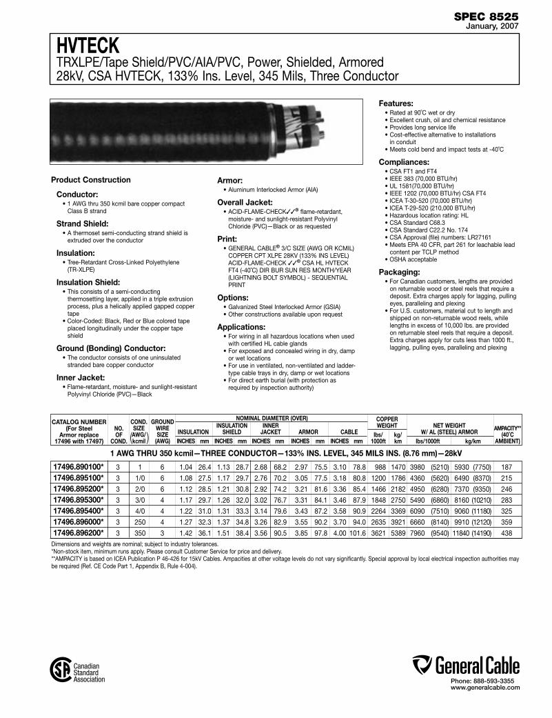
Phone: 888-593-3355www.generalcable.com
HVTECKTRXLPE/Tape Shield/PVC/AIA/PVC, Power, Shielded, Armored 28kV, CSA HVTECK, 133% Ins. Level, 345 Mils, Three Conductor
Dimensions and weights are nominal; subject to industry tolerances.*Non-stock item, minimum runs apply. Please consult Customer Service for price and delivery.**AMPACITY is based on ICEA Publication P 46-426 for 15kV Cables. Ampacities at other voltage levels do not vary significantly. Special approval by local electrical inspection authorities may be required (Ref. CE Code Part 1, Appendix B, Rule 4-004).
CATALOG NUMBER(For Steel
Armor replace17496 with 17497)
NO.OF
COND.
NOMINAL DIAMETER (OVER) INSULATION INNER INSULATION SHIELD JACKET ARMOR CABLE AMPACITY**
(40˚C AMBIENT)
COPPERWEIGHT
lbs/ kg/ 1000ft km
NET WEIGHTW/ AL (STEEL) ARMOR
lbs/1000ft kg/km INCHES mm INCHES mm INCHES mm INCHES mm INCHES mm
1 AWG THRU 350 kcmil—THREE CONDUCTOR—133% INS. LEVEL, 345 MILS INS. (8.76 mm)—28kV
Product Construction
Conductor:• 1 AWG thru 350 kcmil bare copper compact
Class B strand
Strand Shield:• A thermoset semi-conducting strand shield is
extruded over the conductor
Insulation:• Tree-Retardant Cross-Linked Polyethylene
(TR-XLPE)
Insulation Shield:• This consists of a semi-conducting
thermosetting layer, applied in a triple extrusion process, plus a helically applied gapped copper tape
• Color-Coded: Black, Red or Blue colored tape placed longitudinally under the copper tape shield
Ground (Bonding) Conductor:• The conductor consists of one uninsulated
stranded bare copper conductor
Inner Jacket:• Flame-retardant, moisture- and sunlight-resistant
Polyvinyl Chloride (PVC)—Black
Armor:• Aluminum Interlocked Armor (AIA)
Overall Jacket:• ACID-FLAME-CHECK✓✓® flame-retardant,
moisture- and sunlight-resistant Polyvinyl Chloride (PVC)—Black or as requested
Print:• GENERAL CABLE® 3/C SIZE (AWG OR KCMIL)
COPPER CPT XLPE 28KV (133% INS LEVEL) ACID-FLAME-CHECK ✓✓® CSA HL HVTECK FT4 (-40˚C) DIR BUR SUN RES MONTH/YEAR (LIGHTNING BOLT SYMBOL) - SEQUENTIAL PRINT
Options:• Galvanized Steel Interlocked Armor (GSIA)• Other constructions available upon request
Applications:• For wiring in all hazardous locations when used
with certified HL cable glands• For exposed and concealed wiring in dry, damp
or wet locations• For use in ventilated, non-ventilated and ladder-
type cable trays in dry, damp or wet locations• For direct earth burial (with protection as
required by inspection authority)
Features:• Rated at 90˚C wet or dry• Excellent crush, oil and chemical resistance• Provides long service life• Cost-effective alternative to installations
in conduit• Meets cold bend and impact tests at -40˚C
Compliances:• CSA FT1 and FT4• IEEE 383 (70,000 BTU/hr)• UL 1581(70,000 BTU/hr)• IEEE 1202 (70,000 BTU/hr) CSA FT4• ICEA T-30-520 (70,000 BTU/hr)• ICEA T-29-520 (210,000 BTU/hr)• Hazardous location rating: HL• CSA Standard C68.3• CSA Standard C22.2 No. 174• CSA Approval (file) numbers: LR27161• Meets EPA 40 CFR, part 261 for leachable lead
content per TCLP method• OSHA acceptable
Packaging:• For Canadian customers, lengths are provided
on returnable wood or steel reels that require a deposit. Extra charges apply for lagging, pulling eyes, paralleling and plexing
• For U.S. customers, material cut to length and shipped on non-returnable wood reels, while lengths in excess of 10,000 lbs. are provided on returnable steel reels that require a deposit. Extra charges apply for cuts less than 1000 ft., lagging, pulling eyes, paralleling and plexing
COND.SIZE AWG/kcmil
GROUNDWIRESIZE
(AWG)( )
SPEC 8525January, 2007
3 1 6 1.04 26.4 1.13 28.7 2.68 68.2 2.97 75.5 3.10 78.8 988 1470 3980 (5210) 5930 (7750) 187
3 1/0 6 1.08 27.5 1.17 29.7 2.76 70.2 3.05 77.5 3.18 80.8 1200 1786 4360 (5620) 6490 (8370) 215
3 2/0 6 1.12 28.5 1.21 30.8 2.92 74.2 3.21 81.6 3.36 85.4 1466 2182 4950 (6280) 7370 (9350) 246
3 3/0 4 1.17 29.7 1.26 32.0 3.02 76.7 3.31 84.1 3.46 87.9 1848 2750 5490 (6860) 8160 (10210) 283
3 4/0 4 1.22 31.0 1.31 33.3 3.14 79.6 3.43 87.2 3.58 90.9 2264 3369 6090 (7510) 9060 (11180) 325
3 250 4 1.27 32.3 1.37 34.8 3.26 82.9 3.55 90.2 3.70 94.0 2635 3921 6660 (8140) 9910 (12120) 359
3 350 3 1.42 36.1 1.51 38.4 3.56 90.5 3.85 97.8 4.00 101.6 3621 5389 7960 (9540) 11840 (14190) 438
17496.890100* 17496.895100* 17496.895200* 17496.895300*17496.895400* 17496.896000* 17496.896200*
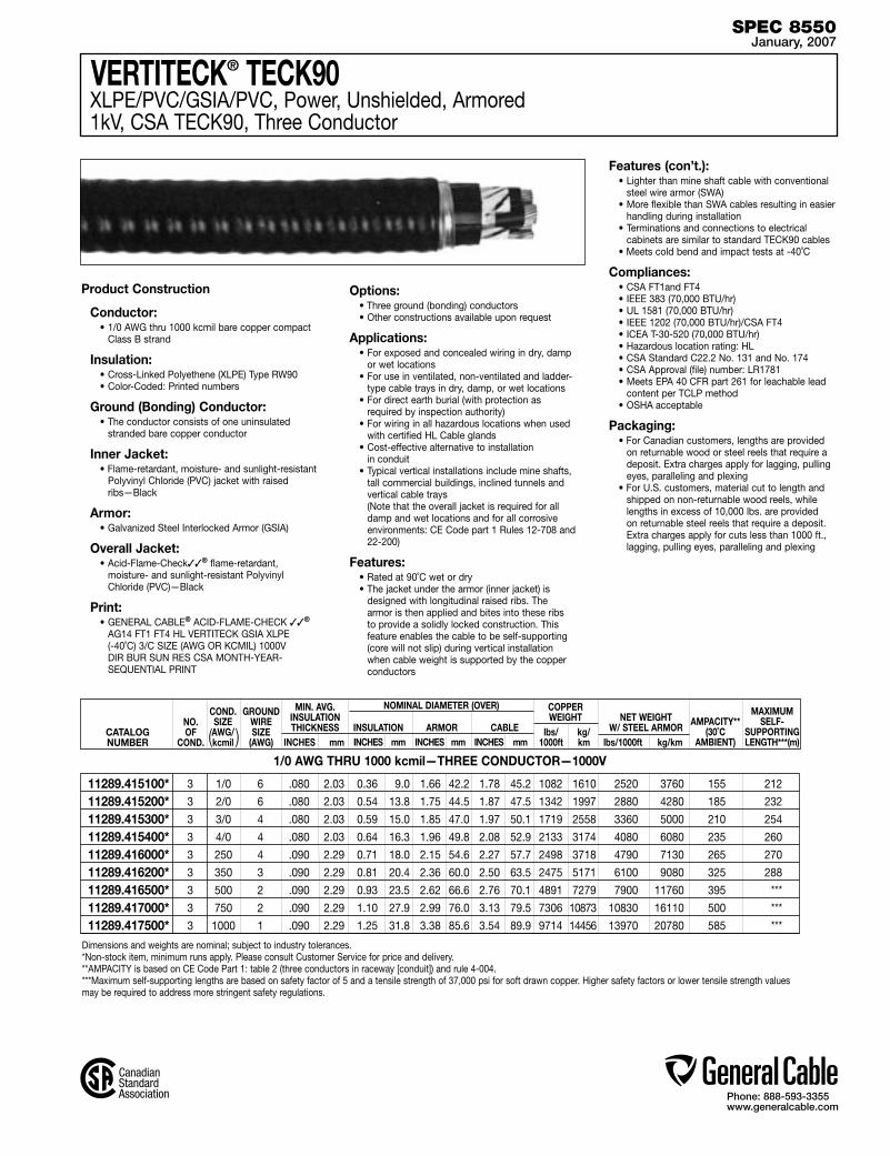
Phone: 888-593-3355www.generalcable.com
VERTITECK® TECK90XLPE/PVC/GSIA/PVC, Power, Unshielded, Armored 1kV, CSA TECK90, Three Conductor
Product Construction
Conductor:• 1/0 AWG thru 1000 kcmil bare copper compact
Class B strand
Insulation:• Cross-Linked Polyethene (XLPE) Type RW90 • Color-Coded: Printed numbers
Ground (Bonding) Conductor:• The conductor consists of one uninsulated
stranded bare copper conductor
Inner Jacket: • Flame-retardant, moisture- and sunlight-resistant
Polyvinyl Chloride (PVC) jacket with raised ribs—Black
Armor:• Galvanized Steel Interlocked Armor (GSIA)
Overall Jacket:• Acid-Flame-Check✓✓® flame-retardant,
moisture- and sunlight-resistant Polyvinyl Chloride (PVC)—Black
Print:• GENERAL CABLE® ACID-FLAME-CHECK ✓✓®
AG14 FT1 FT4 HL VERTITECK GSIA XLPE (-40˚C) 3/C SIZE (AWG OR KCMIL) 1000V DIR BUR SUN RES CSA MONTH-YEAR- SEQUENTIAL PRINT
Options:• Three ground (bonding) conductors• Other constructions available upon request
Applications:• For exposed and concealed wiring in dry, damp
or wet locations• For use in ventilated, non-ventilated and ladder-
type cable trays in dry, damp, or wet locations• For direct earth burial (with protection as
required by inspection authority)• For wiring in all hazardous locations when used
with certified HL Cable glands• Cost-effective alternative to installation
in conduit• Typical vertical installations include mine shafts,
tall commercial buildings, inclined tunnels and vertical cable trays
(Note that the overall jacket is required for all damp and wet locations and for all corrosive environments: CE Code part 1 Rules 12-708 and 22-200)
Features:• Rated at 90˚C wet or dry• The jacket under the armor (inner jacket) is
designed with longitudinal raised ribs. The armor is then applied and bites into these ribs to provide a solidly locked construction. This feature enables the cable to be self-supporting (core will not slip) during vertical installation when cable weight is supported by the copper conductors
Features (con’t.):• Lighter than mine shaft cable with conventional
steel wire armor (SWA)• More flexible than SWA cables resulting in easier
handling during installation • Terminations and connections to electrical
cabinets are similar to standard TECK90 cables• Meets cold bend and impact tests at -40˚C
Compliances:• CSA FT1and FT4• IEEE 383 (70,000 BTU/hr)• UL 1581 (70,000 BTU/hr)• IEEE 1202 (70,000 BTU/hr)/CSA FT4• ICEA T-30-520 (70,000 BTU/hr) • Hazardous location rating: HL• CSA Standard C22.2 No. 131 and No. 174• CSA Approval (file) number: LR1781• Meets EPA 40 CFR part 261 for leachable lead
content per TCLP method• OSHA acceptable
Packaging:• For Canadian customers, lengths are provided
on returnable wood or steel reels that require a deposit. Extra charges apply for lagging, pulling eyes, paralleling and plexing
• For U.S. customers, material cut to length and shipped on non-returnable wood reels, while lengths in excess of 10,000 lbs. are provided on returnable steel reels that require a deposit. Extra charges apply for cuts less than 1000 ft., lagging, pulling eyes, paralleling and plexing
CATALOGNUMBER
NO.OF
COND.
NOMINAL DIAMETER (OVER) INSULATION ARMOR CABLE AMPACITY**
(30˚C AMBIENT)
COPPERWEIGHT
lbs/ kg/ 1000ft km
MIN. AVG.INSULATIONTHICKNESS
INCHES mm
NET WEIGHTW/ STEEL ARMOR
lbs/1000ft kg/km
MAXIMUMSELF-
SUPPORTINGLENGTH***(m) INCHES mm INCHES mm INCHES mm
1/0 AWG THRU 1000 kcmil—THREE CONDUCTOR—1000V
Dimensions and weights are nominal; subject to industry tolerances.*Non-stock item, minimum runs apply. Please consult Customer Service for price and delivery.**AMPACITY is based on CE Code Part 1: table 2 (three conductors in raceway [conduit]) and rule 4-004. ***Maximum self-supporting lengths are based on safety factor of 5 and a tensile strength of 37,000 psi for soft drawn copper. Higher safety factors or lower tensile strength values may be required to address more stringent safety regulations.
COND.SIZE AWG/kcmil
GROUNDWIRESIZE
(AWG)( )
SPEC 8550January, 2007
3 1/0 6 .080 2.03 0.36 9.0 1.66 42.2 1.78 45.2 1082 1610 2520 3760 155 212
3 2/0 6 .080 2.03 0.54 13.8 1.75 44.5 1.87 47.5 1342 1997 2880 4280 185 232
3 3/0 4 .080 2.03 0.59 15.0 1.85 47.0 1.97 50.1 1719 2558 3360 5000 210 254
3 4/0 4 .080 2.03 0.64 16.3 1.96 49.8 2.08 52.9 2133 3174 4080 6080 235 260
3 250 4 .090 2.29 0.71 18.0 2.15 54.6 2.27 57.7 2498 3718 4790 7130 265 270
3 350 3 .090 2.29 0.81 20.4 2.36 60.0 2.50 63.5 2475 5171 6100 9080 325 288
3 500 2 .090 2.29 0.93 23.5 2.62 66.6 2.76 70.1 4891 7279 7900 11760 395 ***
3 750 2 .090 2.29 1.10 27.9 2.99 76.0 3.13 79.5 7306 10873 10830 16110 500 ***
3 1000 1 .090 2.29 1.25 31.8 3.38 85.6 3.54 89.9 9714 14456 13970 20780 585 ***
11289.415100* 11289.415200* 11289.415300* 11289.415400*11289.416000* 11289.416200* 11289.416500* 11289.417000* 11289.417500*
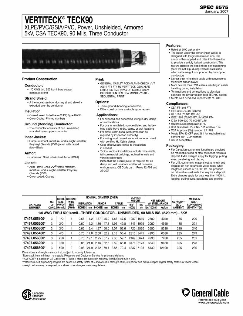
Phone: 888-593-3355www.generalcable.com
VERTITECK® TECK90XLPE/PVC/GSIA/PVC, Power, Unshielded, Armored 5kV, CSA TECK90, 90 Mils, Three Conductor
CATALOGNUMBER
NO.OF
COND.
NOMINAL DIAMETER (OVER) INSULATION ARMOR CABLE AMPACITY**
(30˚C AMBIENT)
COPPERWEIGHT
lbs/ kg/ 1000ft km
NET WEIGHTW/ STEEL ARMOR
lbs/1000ft kg/km
MAXIMUMSELF-
SUPPORTINGLENGTH***(M) INCHES mm INCHES mm INCHES mm
1/0 AWG THRU 500 kcmil—THREE CONDUCTOR—UNSHIELDED, 90 MILS INS. (2.29 mm)—5KV
Product Construction
Conductor:• 1/0 AWG thru 500 kcmil bare copper
compact strand
Strand Shield:• A thermoset semi-conducting strand shield is
extruded over the conductor
Insulation:• Cross-Linked Polyethene (XLPE) Type RW90 • Color-Coded: Printed numbers
Ground (Bonding) Conductor:• The conductor consists of one uninsulated
stranded bare copper conductor
Inner Jacket: • Flame-retardant, moisture- and sunlight-resistant
Polyvinyl Chloride (PVC) jacket with raised ribs—Black
Armor:• Galvanized Steel Interlocked Armor (GSIA)
Jacket:• Acid-Flame-Check✓✓® flame-retardant,
moisture- and sunlight-resistant Polyvinyl Chloride (PVC)
• Color coded: Orange
Print:• GENERAL CABLE® ACID-FLAME-CHECK ✓✓®
AG14 FT1 FT4 HL VERTITECK GSIA XLPE (-40˚C) 3/C SIZE (AWG OR KCMIL) 5000V DIR BUR SUN RES CSA MONTH-YEAR - SEQUENTIAL PRINT
Options:• Three ground (bonding) conductors• Other constructions available upon request
Applications:• For exposed and concealed wiring in dry, damp
or wet locations• For use in ventilated, non-ventilated and ladder-
type cable trays in dry, damp, or wet locations• For direct earth burial (with protection as
required by inspection authority)• For wiring in all hazardous locations when used
with certified HL Cable glands• Cost-effective alternative to installation
in conduit• Typical vertical installations include mine shafts,
tall commercial buildings, inclined tunnels and vertical cable trays
(Note that the overall jacket is required for all damp and wet locations and for all corrosive environments: CE Code part 1 Rules 12-708 and 22-200)
Features:• Rated at 90˚C wet or dry• The jacket under the armor (inner jacket) is
designed with longitudinal raised ribs. The armor is then applied and bites into these ribs to provide a solidly locked construction. This feature enables the cable to be self-supporting (core will not slip) during vertical installation when cable weight is supported by the copper conductors
• Lighter than mine shaft cable with conventional steel wire armor (SWA)
• More flexible than SWA cables resulting in easier handling during installation
• Terminations and connections to electrical cabinets are similar to standard TECK90 cables
• Meets cold bend and impact tests at -40˚C
Compliances:• CSA FT1and FT4• IEEE 383 (70,000 BTU/hr)• UL 1581 (70,000 BTU/hr)• IEEE 1202 (70,000 BTU/hr)/CSA FT4• ICEA T-30-520 (70,000 BTU/hr) • Hazardous location rating: HL• CSA Standard C22.2 No. 131 and No. 174• CSA Approval (file) number: LR1781• Meets EPA 40 CFR part 261 for leachable lead
content per TCLP method• OSHA acceptable
Packaging:• For Canadian customers, lengths are provided
on returnable wood or steel reels that require a deposit. Extra charges apply for lagging, pulling eyes, paralleling and plexing
• For U.S. customers, material cut to length and shipped on non-returnable wood reels, while lengths in excess of 10,000 lbs. are provided on returnable steel reels that require a deposit. Extra charges apply for cuts less than 1000 ft., lagging, pulling eyes, paralleling and plexing
Dimensions and weights are nominal; subject to industry tolerances.*Non-stock item, minimum runs apply. Please consult Customer Service for price and delivery.**AMPACITY is based on CE Code Part 1: Table 2 (three conductors in raceway [conduit]) and rule 4-004. ***Maximum self-supporting lengths are based on safety factor of 5 and a tensile strength of 37,000 psi for soft drawn copper. Higher safety factors or lower tensile strength values may be required to address more stringent safety regulations.
COND.SIZE AWG/kcmil
GROUNDWIRESIZE
(AWG)( )
SPEC 8575January, 2007
3 1/0 6 0.56 14.2 1.77 45.0 1.87 47.5 1082 1610 2700 4020 155 200
3 2/0 6 0.60 15.2 1.86 47.3 1.96 49.8 1343 1999 3060 4550 185 221
3 3/0 4 0.65 16.4 1.97 50.0 2.07 52.6 1720 2560 3550 5280 210 240
3 4/0 4 0.70 17.8 2.08 52.9 2.18 55.4 2315 3445 4290 6380 235 249
3 250 4 0.75 19.1 2.25 57.2 2.35 59.7 2469 3674 4990 7430 265 251
3 350 3 0.85 21.8 2.46 62.5 2.59 65.8 3476 5173 6340 9430 325 278
3 500 2 0.98 24.9 2.72 69.1 2.85 72.4 4837 7198 8130 12100 395 230
17497.055100* 17497.055200* 17497.055300* 17497.055400* 17497.056000* 17497.056200* 17497.056500*

Phone: 888-593-3355www.generalcable.com
VERTITECK® HVTECKTRXLPE/Tape Shield/PVC/GSIA/PVC, Power, Shielded, Armored 15kV, CSA HVTECK, 133% Ins. Level, 220 Mils, Three Conductor
Dimensions and weights are nominal; subject to industry tolerances.*Non-stock item, minimum runs apply. Please consult Customer Service for price and delivery.**AMPACITY is based on ICEA Publication P 46-426 for 15kV Cables. Ampacities at other voltage levels do not vary significantly. Special approval by local electrical inspection authorities may be required (Ref. CE Code Part 1, Appendix B, Rule 4-004).
2 AWG THRU 750 kcmil—THREE CONDUCTOR—133% INS. LEVEL, 220 MILS INS. (5.59 mm)—15kV
Product Construction
Conductor:• 2 AWG thru 750 kcmil bare copper compact
Class B strand
Strand Shield:• A thermoset semi-conducting strand shield is
extruded over the conductor
Insulation:• Tree-Retardant Cross-Linked Polyethylene
(TR-XLPE)
Insulation Shield:• This consists of a semi-conducting
thermosetting layer, applied in a triple extrusion process, plus a helically applied gapped copper tape
• Color Code: black, red, or blue colored tape placed longitudinally under the copper tape shield
Ground (Bonding) Conductor:• The conductor consists of one uninsulated
stranded bare copper conductor
Inner Jacket:• Flame-retardant, moisture- and sunlight-resistant
Polyvinyl Chloride (PVC)—Black
Armor:• Galvanized Steel Interlocked Armor (GSIA)
Overall Jacket:• ACID-FLAME-CHECK✓✓® flame-retardant,
moisture- and sunlight-resistant Polyvinyl Chloride (PVC)—Red
Print:• GENERAL CABLE® ACID-FLAME-CHECK ✓✓®
AG14 FT1 FT4 HL VERTITECK® GSIA XLPE (-40˚C) 3/C SIZE (AWG OR KCMIL) 15,000V DIR BUR SUN RES CSA MONTH-YEAR - SEQUENTIAL PRINT
Options:• Three ground (bonding) conductors
Applications:• For exposed and concealed wiring in dry, damp
or wet locations• For use in ventilated, non-ventilated and ladder-
type cable trays in dry, damp or wet locations• For direct earth burial (with protection as
required by inspection authority)• For wiring in all hazardous locations when used
with certified HL Cable glands• Cost-effective alternative to installation
in conduit• Typical vertical installations include mine shafts,
tall commercial buildings, inclined tunnels and vertical cable trays
(Note that the overall jacket is required for all damp and wet locations and for all corrosive environments: CE Code part 1 Rules 12-708 and 22-200
Features:• Rated at 90˚C wet or dry• The jacket under the armor (inner jacket) is
designed with longitudinal raised ribs. The armor is then applied and bites into these ribs to provide a solidly locked construction. This feature enables the cable to be self-supporting (core will not slip) during vertical installation when cable weight is supported by the copper conductors
• Lighter than mine shaft cable with conventional steel wire armor (SWA)
• More flexible than SWA cables resulting in easier handling during installation
• Terminations and connections to electrical cabinets are similar to standard TECK90 cables
• Meets cold bend and impact tests at -40˚C
Compliances:• CSA FT1 and FT4• IEEE 383 (70,000 BTU/hr)• UL 1581(70,000 BTU/hr)• IEEE 1202 (70,000 BTU/hr) CSA FT4• ICEA T-30-520 (70,000 BTU/hr)• ICEA T-29-520 (210,000 BTU/hr)• Hazardous location rating: HL• CSA Standard C68.3• CSA Standard C22.2 No. 174• CSA Approval (file) numbers: LR27161• Meets EPA 40 CFR, part 261 for leachable lead
content per TCLP method• OSHA acceptable
Packaging:• For Canadian customers, lengths are provided
on returnable wood or steel reels that require a deposit. Extra charges apply for lagging, pulling eyes, paralleling and plexing
• For U.S. customers, material cut to length and shipped on non-returnable wood reels, while lengths in excess of 10,000 lbs. are provided on returnable steel reels that require a deposit. Extra charges apply for cuts less than 1000 ft., lagging, pulling eyes, paralleling and plexing
SPEC 8600January, 2007
CATALOG NUMBER(For Steel
Armor replace17496 with 17497)
NO.OF
COND.
NOMINAL DIAMETER (OVER) INSULATION INNER INSULATION SHIELD JACKET ARMOR CABLE
COPPERWEIGHT
lbs/ kg/ 1000ft km
NET WEIGHT lbs/1000ft kg/km INCHES mm INCHES mm INCHES mm INCHES mm INCHES mm
COND.SIZE AWG/kcmil
GROUNDWIRESIZE
(AWG)( )
3 2 6 0.76 19.3 0.83 21.1 2.12 53.9 2.41 61.2 2.55 64.8 793 1180 3970 5908
3 1 6 0.79 20.1 0.86 21.9 2.20 55.9 2.49 63.3 2.63 66.8 964 1435 4273 6359
3 1/0 6 0.83 21.1 0.89 22.6 2.27 57.7 2.56 65.0 2.58 65.5 1175 1749 4430 6592
3 2/0 6 0.86 21.8 0.93 23.6 2.36 59.9 2.65 67.3 2.67 67.8 1438 2140 5001 7442
3 3/0 4 0.91 23.0 0.98 24.9 2.46 62.5 2.75 69.9 2.77 70.4 1821 2710 5406 8045
3 4/0 4 0.96 24.3 1.03 26.2 2.57 65.3 2.86 72.6 2.88 73.2 2248 3345 6164 9173
3 250 4 1.02 25.8 1.08 27.5 2.69 68.3 2.98 75.7 3.00 76.2 2607 3880 6824 10155
3 350 3 1.12 28.3 1.20 30.5 3.00 76.2 3.29 83.6 3.33 84.6 3597 5353 8171 12159
3 500 3 1.24 31.5 1.32 33.6 3.26 82.8 3.55 90.2 3.59 91.2 5022 7474 10277 15293
3 750 2 1.42 36.0 1.51 38.3 3.67 93.2 3.96 100.6 4.00 101.6 7452 11090 13357 19877
17497.540200 17497.540100 17497.545100 17497.545200 17497.54530017497.545400 17497.546000 17497.54620017497.546500 17497.547000

Phone: 888-593-3355www.generalcable.com
Industrial Cables Date of Issue 01/07
Technical Information
Section A General Technical InformationSPECIFICATION # DESCRIPTION REVISION DATE
A005 Glossary Jan. 2007
A025 Reference Standards Jan. 2007
A050 Checklist for Specifications Jan. 2007
A075 NEC and CSA Designations Jan. 2007
A100 Common Color Sequence Jan. 2007
A150 Metric Conversion Factors Jan. 2007
A200 Reel Capacity Chart Jan. 2007
Section B Conductor DataSPECIFICATION # DESCRIPTION REVISION DATE
B005 Conductor Reference Jan. 2007
B025 Class B Conductors for General Wiring Jan. 2007
B030 Class C Conductors for General Wiring Jan. 2007
B035 Class H Conductors for General Wiring Jan. 2007
B040 Class I Conductors for General Wiring Jan. 2007
B045 Class K Conductors for General Wiring Jan. 2007
Section C Material PropertiesSPECIFICATION # DESCRIPTION REVISION DATE
C005 Thermoplastic Jacket and Insulation Material Properties Jan. 2007
C010 Thermoset Jacket and Insulation Material Properties Jan. 2007
Section D Handling and Storage RecommendationsSPECIFICATION # DESCRIPTION REVISION DATE
D005 Recommended Reel Handling Practices Jan. 2007
D025 Recommended Cable Handling Practices Jan. 2007
D050 Recommended Cable Storage Practices Jan. 2007
Phone: 888-593-3355www.generalcable.com
Industrial Cables Date of Issue 02/07
Technical Information
Section E Cable Installation GuidelinesSPECIFICATION # DESCRIPTION REVISION DATE
E005 Pre-Installation Instructions Jan. 2007
E025 Installation — Overview and Checklist Jan. 2007
E050 Installation — Feed-In Setups Jan. 2007
E075 Installation — Conductor Maximum Pulling Tensions Jan. 2007
E100 Installation — Training and Bending Limitations Jan. 2007
E125 Installation — Maximum Sidewall Pressure Jan. 2007
Section F Cable TestingSPECIFICATION # DESCRIPTION REVISION DATE
F005 DC “Hi Pot” Pre-Test Guidelines for MV Cables Jan. 2007
F025 DC “Hi Pot” Testing Guidelines for MV Cables Jan. 2007
F075 Field Electrical “Hi Pot” Testing Guidelines Jan. 2007
F100 Emergency Overload Current Guidelines Jan. 2007
F125 Short Circuit Current Calculation Overview Jan. 2007
F150 Short Circuit Current for Copper Shields Jan. 2007

Phone: 888-593-3355www.generalcable.com
Glossary
Abrasion Resistance: Ability of a wire, cable or material to resist surface wear.
Accelerated Aging: A test in which voltage, temperature, etc. are increased above normal operating values to obtain observable deterioration in a relatively short period of time. The plotted results give expected service life under normal conditions.
ACM: Aluminum conductor material.
Accelerator: A chemical additive that hastens a chemical reaction under specific conditions.
Admittance: The measure of the ease with which an alternating current flows in a circuit. The reciprocal of impedance.
AEIC: Association of Edison Illuminating Companies
Aerial Cable: A cable suspended in the air on poles or another overhead structure.
Aging: The change in properties of a material with time under specific conditions.
AIA: Aluminum Interlocked Armor.
Alloy: A metal formed by combining two or more different metals to obtain desirable properties.
Alternating Current: Electric current that continually reverses its direction. It is expressed in cycles per second (hertz or Hz).
Ambient Temperature: The temperature of the medium surrounding an object. Generally a lower temperature than the temperature at which the cable is operating.
American Wire Gauge (AWG): A standard North American system for designating wire diameter.
Ampacity: See Current Carrying Capacity.
Ampere: The unit of current. One ampere is the current flowing through one ohm of resistance at one volt potential.
Analog: A data format using continuous physical variables such as voltage amplitude or frequency variations.
Anneal (Soften): Relief of mechanical stress through heat and gradual cooling. Annealing copper renders it less brittle.
Armor: A protective metal covering commonly in the form of flexible interlocking aluminum or steel tape, steel wires or aluminum sheath.
ASTM: American Society for Testing and Materials.
Attenuation: The general term used to denote the decrease of power from one point to another. In fiber optics, the optical power loss per unit length is expressed logarithmically in decibels per kilometer (dB/km) at a specific wavelength.
Audio Frequency: The range of frequencies audible to the human ear. Usually 20-20,000 Hz.
AWM: Designation for appliance wiring material.
Balanced Circuit: One utilizing cables having two or more identical conductors with the same electromagnetic characteristics in relation to each other and to ground.
Band Marking: A continuous circumferential band applied to a conductor at regular intervals for identification.
Bandwidth: (1) The difference between the upper and lower limits of a given band of frequencies. Expressed in Hertz. (2) A measure of the maximum frequency range over which light intensity exiting a waveguide one kilometer in length can be varied before the attenuation varies 3dB from the mean. The greater the bandwidth, the greater the information-carrying capacity. Bandwidth is expressed in Megahertz (MHz)–Kilometer (km).
Bending Radius: Radius of curvature that a cable can be safely bent without any adverse effects.
Binder: A spirally served tape used for holding assembled cable components in place awaiting subsequent manufacturing operations.
Bonding Conductor: An insulated or uninsulated conductor forming part of the cable assembly which is used for the purpose of connecting non-current carrying parts of electrical equipment to a system grounding conductor.
Braid: A fibrous or metallic group of filaments interwoven in cylindrical shape to form a covering over one or more wires.
Braid Angle: The smaller of the two angles formed by the shielding strand and the axis of the cable being shielded.
Braid Carrier: A spool or bobbin on a braider that holds one group of strands or filaments consisting of a specific number of ends. The carrier revolves during braiding operations.
Braid Ends: The number of strands used to make up one carrier. The strands are wound side-by-side on the carrier bobbin and lie parallel in the finished braid.
Breakdown Voltage: The voltage at which the insulation between two conductors breaks down.
B & S Gauge: The same as American Wire Gauge (AWG).
Buffer: A protective coating over an optical fiber.
Building Wire: A general term used for light and power wiring products, 1000 volts or less.
Bunch Stranding: A group of wires of the same diameter twisted together without a predetermined pattern. Used in flexible cords and cables.
Buried Cable: A cable installed directly in the earth without use of underground conduit. Also called “direct burial cable.”
Butyl Rubber: A synthetic rubber with good insulating properties (i.e. low voltage cords).
SPEC A005January, 2007
Phone: 888-593-3355www.generalcable.com
Glossary
Cable: An insulated conductor, or group of individually insulated conductors in one assembly.
Cabling: The twisting together of two or more insulated conductors to form a cable.
Capacitance: The ratio of the electrostatic charge on a conductor to the potential difference between the conductors required to maintain that charge. Units expressed in Farads.
Capacitive Coupling: Electrical interaction between two conductors caused by the capacitance between them.
Capacitive Reactance (Xc): The opposition to alternating current due to the capacitance of the cable or circuit. Measured in ohms.
CE Code, CEC: Canadian Electrical Code
Certified Test Report (CTR): A report providing actual test data on a cable. Tests are normally conducted by the Quality Control Department to confirm that the product being shipped conforms to specifications.
Characteristic Impedance: The impedance that, when connected to the output terminals of a transmission line of any length, makes the line appear infinitely long. The ratio of voltage to current at every point along a transmission line on which there are no standing waves.
Circular Mil (cmil): The area of a circle one mil (.001") in diameter (7.854 x 10⁻⁷ sq in). Used in expressing wire cross-sectional area.
Circuit Sizes: A popular term for building wire sizes 14 through 10 AWG.
Cladding: (1) A method of applying a layer of metal over another metal whereby the junction of the two metals is continuously welded. (2) A low refractive index material that surrounds the core of an optical fiber causing the transmitted light to travel down the core and protects against surface contaminant scattering.
Coaxial Cable: A cable consisting of two cylindrical conductors with a common axis, separated by a dielectric.
Cold Flow: Permanent deformation of the insulation or jacket due to mechanical force or pressure (not due to heat softening).
Color Code: A system for circuit identification through use of solid colors and contrasting tracers.
Composite Cable: One containing more than one type or gauge size of conductors (e.g. power and control conductors in one assembly).
Compound: An insulating or jacketing material made by mixing two or more polymeric ingredients.
Concentric Stranded Conductors: Manufactured to ASTM, ICEA and CSA standards. The most common fixed installation type conductors are: 1) Round—no diameter reduction; 2) Compressed—approximately 3% diameter reduction; 3) Compact—approximately 10% diameter reduction.
Concentric Stranding: A central wire surrounded by one or more layers of helically wound strands in a fixed round geometric arrangement.
Concentricity: The measurement of the location of the center of the conductor with respect to the geometric center of the surrounding insulation.
Conductivity: The capacity of a material to carry electrical current—usually expressed as a percentage of copper conductivity (copper being 100%).
Conductor: An uninsulated wire suitable for carrying electrical current.
Conductor Shield: An extrusion of black semi-conducting thermoses material over the conductor to provide a smooth interface with the insulation for even distribution of electrical stress.
Conduit (Electrical Raceway): A tube or pipe in which insulated wires and cables are run.
Connector: A device used to physically and electrically connect two or more conductors. Also used to physically connect cable to equipment.
Continuity Check: A test to determine whether electrical current flows continuously throughout the length of a single wire or individual wires in a cable.
Continuous Vulcanization: Simultaneous extrusion and vulcanization of rubber-like (thermoset) coating materials. Often referred to as CV.
Control Cable: A multi-conductor cable made for operation in control of signal circuits.
Copolymer: A compound resulting from the polymerization of two different monomers.
Copperweld®: The trade name of Flexo Wire Division (Copperweld Steel Corp.) for its copper-clad steel conductors.
Cord: A small, flexible, insulated wire or cable.
Core: In cables, a component or assembly of components over which additional components (shield, sheath, etc.) are applied.
Corona: A discharge due to ionization of air around a conductor due to a potential gradient exceeding a certain critical value.
Coverage: The percent of completeness with which a metal serving covers the underlying surface.
CPE: Chlorinated polyethylene can be used as either a thermoplastic or thermoset. It is a tough chemical- and oil-resistant material and makes an excellent jacket for industrial control cable. As a thermoset, it can be used as an oil-resistant cord jacket. Typical temperature ratings range from -35˚C to 90˚C. Other outstanding properties include low water absorption and super crush resistance, which are important attributes in industrial control applications.
Creep: The dimensional change with time of a material under a mechanical load.
SPEC A005January, 2007
Phone: 888-593-3355www.generalcable.com
Glossary
Cross-linked: Inter-molecular bonds between long-chain thermoplastic polymers by chemical or electron bombardment means. The properties of the resulting thermosetting material are usually improved (e.g. XLPE).
Crosstalk: Signal interference between nearby conductors caused by pickup of stray energy.
CSA: Canadian Standards Association
Current Carrying Capacity (Ampacity): The maximum current an insulated conductor can safely carry without exceeding its insulation and jacket temperature limitations.
Cut-Through Resistance: The ability of a material to withstand cutting from a sharp edge or small radius under pressure.
Decibel (dB): A unit to express differences of power level. Used to express power gain in amplifiers or power loss in passive circuits or cables. The units in which the ratio of two power levels, P1 and P2, are expressed. The ratio in dB is given as - 10 log10 (P1/P2).
P2 → → P1
Delay Line: A cable made to provide very low velocity of propagation with long electrical delay for transmitted signals.
Derating Factor: A factor used to reduce the current carrying capacity of a wire when used in environments other than that for which the value was established.
Dielectric: Any insulating material between two conductors that permits electrostatic attraction and repulsion to take place across it.
Dielectric Constant (K): The ratio of the capacitance of a condenser with dielectric between the electrodes to the capacitance when air is between the electrodes. Also called Permittivity and Specific Inductive Capacity (SIC).
Dielectric Strength: The voltage which an insulation can withstand before breakdown occurs. Usually expressed as a voltage gradient (such as volts per mil).
Dielectric Test: A test in which a voltage higher than the rated voltage is applied for a specified time to determine the adequacy of the insulation under normal conditions. Sometimes called a “Hi-Pot” test (high potential).
Digital: A data format that uses discrete or separate physical levels to contain information.
Direct Burial Cable: A cable installed directly in the earth.
Direct Current: An electric current that flows in only one direction.
Direction of Lay: The lateral direction in which the strands of a conductor run over the top of the cable conductor as they recede from an observer looking along the axis of the conductor or cable. Also applies to twisted cable.
Dissipation Factor: The tangent of the loss angle of the insulating material. (Also referred to as loss tangent, tan d and approximate power factor.)
Drain Wire: The uninsulated wire in contact with an electrostatic shield throughout its length, in an instrumentation or control cable, used to discharge unwanted signals. Also provides a means of terminating laminated shields. Sometimes used to describe the metallic shielding wires of a power cable insulation shield.
Drawing: In wire manufacturing, pulling the metal through a die or series of dies to reduce diameter to a specified size.
Earth: British terminology for zero-reference “ground.”
Eccentricity: Like concentricity, a measure of the center of a conductor’s location with respect to the circular cross section of the insulation. Expressed as a percentage of displacement of one circle within the other.
EEMAC: Electrical and Electronic Manufacturers Association of Canada (U.S. counterpart is NEMA).
Elastomer: A rubber-like substance. Any material that will return to its original dimensions after being stretched or distorted.
Electrostatic Shield: A copper or laminated aluminum/Mylar® tape wrap around a signal or instrumentation circuit (pair, triad, etc.) to protect from the electric field radiated by a voltage source. The grounded shield intercepts static interference and carries it off to ground.
Elongation: The fractional increase in length of material stressed in tension.
EMI: Abbreviation for electromagnetic interference.
EMRC: Energy Mines and Resources Canada
EPDM: Ethylene-propylene-diene monomer rubber. A material with good electrical insulating properties.
EPR: Ethylene-propylene copolymer rubber. A material with good electrical insulating properties.
Equal Load Sharing: An even distribution of current between the parallel cables in a power circuit.
Equilay: See Unilay: More than one layer of helically laid wires with the length of the lay the same for each layer.
Farad: A unit of electrical capacity.
Fatigue Resistance: Resistance to metal crystallization which leads to conductors or wires breaking from flexing.
Ferrous: Composed of and/or containing iron. A ferrous metal exhibits magnetic characteristics (e.g. steel armor).
FEP: Fluorinated ethylene propylene insulated wire (see Teflon®).
Fiber: A single, separate optical transmission element characterized by core and cladding.
Fiber Optics: Light transmission through optical fibers for communication and signaling.
SPEC A005January, 2007
Phone: 888-593-3355www.generalcable.com
Glossary
Filled Cable: Cable construction in which the cable core is filled with a material that will prevent moisture or gasses from entering or passing through the cable.
Filler: 1) A material used in multi- conductor cables to occupy large interstices formed by the assembled conductors; 2) An inert substance added to a compound to improve properties.
Flat Cable: A cable with two essentially flat surfaces (e.g. NMD90).
Flat Conductor: A wire having a rectangular cross section as opposed to round or square conductors.
Flame Resistance: The ability of a material not to propagate flame once the heat source is removed (see FT1).
Flammability: The measure of the material’s ability to support combustion.
Flex Life: The measurement of the ability of a conductor or cable to withstand repeated bending before breaking.
Flexibility: The ease with which a cable may be bent without sustaining damage.
FT1: One of several CSA flame test designations for wires and cables which pass the C22.2 No. 0.3 test requirements. (Other designations include FT2, FT4, etc.).
Fusion Splice: A splice accomplished by the application of localized heat sufficient to fuse or melt the ends of two lengths of optical fiber, forming a continuous single fiber.
Gauge: A term used to denote the physical size of a wire.
GND: Abbreviation for ground.
Graded-Index: A type of optical fiber in which the refractive index of the core is in the form of a parabolic curve, decreasing toward the cladding. This type of fiber provides high bandwidth capabilities.
Ground (GND): 1) A conducting connection between an electrical circuit and the earth, or other large conducting body, to serve as an earth thus making a complete electrical circuit; 2) Term used for non-current carrying conductor in a cable (see Bonding Conductor).
Halogen: A term used to identify any of the four elements chlorine, fluorine, bromine and iodine, grouped together because their chemical properties are similar.
Hard Drawn Copper Wire: Copper wire that has not been annealed after drawing.
Heat Shock: A test to determine stability of a material by sudden exposure to a high temperature for a short period of time.
Henry: The unit of inductance.
Hertz (Hz): A term replacing cycles-per-second as an indication of frequency.
Hi-Pot (High Potential): A test designated to determine the highest voltage that can be applied to a conductor without breaking down the insulation (see Dielectric Test).
High Voltage (HV): Generally, a wire or cable with an operating voltage of over 600 volts.
Hook-Up Wire: A wire used for low current, low voltage (under 1000 volts) applications within enclosed electronic equipment.
Hygroscopic: A material capable of absorbing moisture from the air.
Hypalon®: DuPont’s trade name for their chlorosulfonated polyethylene, an ozone-resistant synthetic rubber.
ICEA (formerly IPCEA): Insulated Cable Engineers Association.
IEEE: Institute of Electrical and Electronics Engineers.
Impact Strength: A test for determining the mechanical punishment a cable can withstand without physical or electrical breakdown by impacting with a given weight, dropped a given distance, in a controlled environment.
Impedance: The total opposition that a circuit offers to the flow of alternating current or any other varying current at a particular frequency. It is a combination of resistance R and reactance X, measured in ohms.
Inductance: The property of a circuit or circuit element that opposes a change in current flow, thus causing current changes to lag behind voltage changes. It is measured in henrys.
Insulation: A material having good dielectric properties permitting close assembly of conductors in cable and equipment.
Insulation Level: A designation used to identify the insulation thickness required to protect a high voltage cable under ground fault conditions. Expressed as a percentage (e.g. 100% level, 133% level).
Insulation Shield (HV Cable): A two-part shield consisting of a non-metallic component and a metallic component. The first component is an extrusion of black semi-conducting thermoset material over the insulation, which provides uniform radial stress distribution across the insulation. The second component is a metallic shield which is typically copper tape or wire that functions as a bonding (grounding) conductor and/or a neutral conductor. The metallic shield also serves to conduct ground fault current in the event of insulation failure. See also Drain Wire.
Insulation Stress: High voltage stress which causes molecular separation in the insulation at sharp projections in the conductor. Controlled by conductor and insulation shielding, called a stress relief shield. Measured in volts per mil.
Interaxial Spacing: Center-to-center conductor spacing.
Interstices: Voids or valleys between individual strands in a conductor or between insulated conductors in a multi-conductor cable (intersticial spaces).
SPEC A005January, 2007
Phone: 888-593-3355www.generalcable.com
Glossary
Irradiation: In insulations, the exposure of the material to high energy emissions for the purpose of favorably altering the molecular structure by crosslinking.
Jacket: An outer covering, usually non-metallic, mainly used for protection against the environment.
kcmil: One thousand circular mils (MCM).
kilo: A prefix denoting 1000 (103).
kV: Kilovolt (1000 volts).
Laminated Tape: A tape consisting of two or more layers of different materials bonded together (e.g. aluminum/Mylar®).
Lay: The length measured along the axis of a wire or cable required for a single strand (in stranded wire) or conductor (in cable) to make one complete turn about the axis of the conductor or cable.
Lay Direction: The twist in the cable as indicated by the top strands while looking along the axis of the cable away from the observer. Described as “right hand” or “left hand.”
Leakage Current: The undesirable flow of current through or over the surface of an insulation.
Line Drop (Voltage Drop): A voltage loss occurring between any two points in a power circuit. Such loss, or drop, is due to the resistance, reactance or leakage of the circuit, type of cable and configuration.
Line Voltage: The value of the potential existing on a supply or power line. Rated voltage of cables.
LOCA: Abbreviation for loss of coolant accident, a system malfunction associated with nuclear generating stations.
Longitudinal Shield: A tape shield, flat or corrugated, applied longitudinally with the axis of the core being shielded.
Loss Factor: The product of the dissipation and dielectric constant of an insulating material.
µA. Microampere: One-millionth of an ampere (10-6).
mA. Milliampere: One-thousandth of an ampere (10-3).
Magnetic Noise: Caused by current frequency. An AC powerline creates a magnetic field around that cable, this magnetic field causes the magnetic noise in neighboring control or instrumentation circuits.
MCM: One thousand circular mils (kcmil).
meg or mega: A prefix denoting 1,000,000 (106).
Megarad: A unit for measuring radiation dosage.
Messenger: The linear supporting member, usually a high-strength steel wire, used as the supporting element of a suspended aerial cable. The messenger may be an integral part of the cable, or exterior to it.
Mho: The unit of conductivity. The reciprocal of an ohm.
micro: A prefix denoting one-millionth (10-6).
micron: (m) Millionth of a meter = 10-6 meter.
Mil: A unit of length equal to one-thousandth of an inch (.001"). Common unit for insulation thickness.
Milli: A prefix denoting one-thousandth (10-6).
Modulus of Elasticity: The ratio of stress to strain in an elastic material.
Moisture Absorption: The amount of moisture, in percentage, that a material will absorb under specified conditions.
Moisture Resistance: The ability of a material to resist absorbing moisture from the air or when immersed in water.
Multi-Conductor Cable: A cable consisting of two or more conductors, either cabled or laid in a flat parallel construction, with or without a common overall covering.
Multi-Plexed Conductors: Three or more completed cables together without fillers or common overall jacket. (Triplexed, 3-1|C; Quadruplet, 4-1|C)
Mutual Capacitance: Capacitance between two conductors when all other conductors, including ground, are connected together.
Mylar®: DuPont trade name for a polyester material.
Nano: A numerical prefix denoting one-billionth (10-9).
National Electrical Code (NEC): A U.S. consensus standard published by the National Fire Protection Association (NFPA) and incorporated in OSHA regulations. (Canadian Counterpart is the CE Code).
NEMA: National Electrical Manufacturers Association. (Canadian counterpart is EEMAC).
Neoprene: A synthetic rubber with good resistance to oil, chemicals and flame. Also called polychloroprene.
Nomex®: DuPont trademark for a temperature-resistant, flame-retardant nylon.
Non Hygroscopic: A material incapable of taking up or absorbing moisture from the air.
Nylon®: An abrasion-resistant thermoplastic with good chemical resistance. A DuPont registered trademark.
OHM: The electrical unit of resistance.
OSHA: Abbreviation for the U.S. Occupational Safety and Health Act.
Overlap: The amount the trailing edge laps over the leading edge of a spiral tape wrap.
Oxygen Index: Percentage of oxygen necessary to support combustion in a gas mixture. Flame-retardant materials have a higher oxygen index.
Pair: Two insulated wires of a single circuit twisted together or laid parallel.
Parallel Cable: Two or more cables used to share the current in heavily loaded power circuits which permits the use of smaller conductors.
SPEC A005January, 2007
Phone: 888-593-3355www.generalcable.com
Glossary
Percentage Conductivity: Conductivity of a material expressed as a percentage of that of copper. Also used to indicate ratio of conductance between the phase conductor and the neutral in power cables.
Pick: Distance between two adjacent crossover points of braid filaments. The measurement in picks per inch indicates the degree of coverage.
pico: A prefix denoting one-millionth of one-millionth (10-12).
Pitch: In flat cable, the nominal distance between the index edges of two adjacent conductors.
Pitch Diameter: Diameter of a circle passing through the center of the conductors in any layer of a multi-conductor cable.
Plastic Deformation: Change in dimensions under load that is not recovered when the load is removed.
Plasticizer: A chemical agent added to plastics to make them softer and more pliable.
Plenum Cable: Cable approved for installation in plenums, (e.g. suspended ceiling) without the need for conduit.
Polyester: Polyethylene terephthalate which is used extensively in the production of a high-strength, moisture-resistant film used as a cable core wrap (see Mylar®).
Polyethylene (PE): A thermoplastic material having excellent electrical and physical properties.
Polymer: A material of high molecular weight formed by the chemical union of monomers.
Polyolefin: A family of thermoplastics based upon the unsaturated hydrocarbons know as olefins. When combined with butylene or styrene polymers, they form compounds such as polyethylene and polypropylene.
Polypropylene (PPE): A thermoplastic similar to polyethylene but stiffer and having a higher softening point (temperature).
Polyurethane/PUR: This thermoplastic material is used primarily as a cable jacket material. It has excellent oxidation, oil and ozone resistance. Some formulations also have good flame resistance. It is a hard material with excellent abrasion resistance. It has outstanding “memory” properties, making it an ideal jacket material for retractile cords.
Polyvinyl Chloride (PVC): A general- purpose thermoplastic used for low voltage wire and cable insulation, and for jackets.
Power Factor: The ratio of resistance to impedance. The ratio of the actual power of an alternating current to apparent power. Mathematically, the cosine of the angle between the voltage applied and the current resulting.
Primary Insulation: The first layer of non-conductive material applied over a conductor, whose prime function is to act as electrical insulation.
Pulling Eye: A device fastened to a cable to which a hook may be attached in order to pull the cable.
Quad: Four insulated wires of a single circuit.
REA: Rural Electrification Administration. A branch of the U.S. Department of Agriculture.
Reactance: The opposition offered to the flow of alternating current by inductance or capacitance of a component or circuit.
Reel Drum Diameter: Diameter of the drum (or hub) of the reel.
Reel Flange Diameter (Reel Height): Diameter of the reel flanges.
Reel Traverse: Width of space between reel flanges.
Reel Width: Overall width of reel.
Ridge Marker: One or more ridges running laterally along the outer surface of a insulated wire or cable for purposes of identification.
Root Mean Square (RMS): The effective value of an alternating current or voltage.
Rope Lay Conductor: A conductor composed of a central core surrounded by one or more layers of helically laid groups of wires used in portable cables.
Rubber: A general term used to describe wire insulation and jackets made of thermosetting elastomers, such as natural or synthetic rubbers, EPR, neoprene, Hypalon, butyl rubber and others.
SBR: A copolymer of styrene and butadiene. Also GR-S or Buna-S. Most commonly used type of synthetic rubber.
Self-Extinguishing: The characteristic of a material whose flame is extinguished after the igniting flame is removed.
Semi-Conductor: In wire industry terminology, a material possessing electrical conductivity that falls somewhere between that of conductors and insulators. Usually made by adding carbon particles to an insulator (e.g. conductor shield and insulation shield). Not the same as semi-conductor materials such as silicon, germanium, etc. used for making transistors and diodes.
Separator: Pertaining to wire and cable, a layer of insulating material such as textile paper, Mylar®, etc. which is placed between a conductor and its dielectric, between a cable jacket and the components it covers or between various components of a multi- conductor cable. It can be utilized to improve stripping qualities, flexibility or can offer additional mechanical or electrical protection to the components it separates.
Served Wire Armor (SWA): Spiral wrap of galvanized steel wires applied around a cable to afford mechanical protection and increase the cable pulling tension characteristics (mineshaft, submarine cable, etc.). Also used to denote steel wire armor.
Sheath: The outer covering or jacket of a multi-conductor cable. Usually non-metallic.
SPEC A005January, 2007

Phone: 888-593-3355www.generalcable.com
Glossary
Shield (Electrostatic): In cables, a metallic layer placed around a conductor or group of conductors to prevent electrostatic interference between the enclosed wires and external fields. Also see Insulation Shield.
Shrink Tubing: Tubing which has been extruded, crosslinked and mechanically expanded which, when reheated, will return to its original diameter.
SIA: Steel Interlocked Armor.
Side Wall Bearing Pressure (SWBP): A term used in reference to the pressure on a cable which is being pulled around a curved surface under tension. If excessive, SWBP can damage cable components and reduce the life of the cable.
Signal Cable: A cable designed to carry current of usually less than one ampere per conductor to operate signal circuit devices.
Silicone: A material made from silicone and oxygen. Can be in thermosetting elastomer or liquid form. The thermosetting elastomer form is noted for high heat resistance.
Skin Effect: The tendency of alternating current to concentrate and to travel only on the surface of a conductor. Tendency increases with increase in frequency.
Sleeving: An extruded tube.
Spark Test: A test designed to locate imperfections (usually pin-holes) in the insulation of a wire or cable by application of voltage for a very short period of time while the wire is being drawn through the electrode field.
Specific Gravity: The ratio of the density (mass per unit volume) of a material to that of water.
Specific Inductive Capacity (SIC): Same as dielectric constant. See Dielectric Constant.
Tank Test: A voltage insulation test in which the insulated wire or cable is submerged in water and voltage is applied between the conductor and water serving as ground. Shielded cables are generally not tank tested due to the possibility of introducing contaminants on the outer surface of the insulation.
Teflon®: DuPont Company trademark for fluorocarbon resins. See FEP and TFE.
Temperature Rating: The maximum temperature at which an insulating material may be used in continuous operation without loss of its basic properties (i.e. operating, overload, short circuit). The minimum temperature for safe handling.
Tensile Strength: The pull stress required to break a given specimen. Measured in pounds per square inch. Also referred to as Ultimate Tensile Strength.
TFE: Tetrafluoroethylene. A thermoplastic material with good electrical insulating properties and chemical and heat resistance.
Thermoplastic: A material that can be softened repeatedly by heating and hardened by cooling through a temperature range characteristic of the plastic, and that in the softened state can be shaped by molding or extrusion.
Thermoset: A material that has been vulcanized by heat or other means and is substantially infusible and insoluble.
Three-Conductor Cable: Three insulated conductors assembled with other necessary cable components (shield, filler, etc.) to form a core, protected by an overall jacket.
Tinned Copper: Tin coating added to copper to aid in soldering and inhibit corrosion.
Tray: A cable tray system is a unit or assembly of units or sections, and associated fittings, made of non-combustible materials forming a rigid structural system used to support cables. Cable tray systems (previously termed Continuous Rigid Cable Supports) include ladders, troughs, channels, solid bottom trays and similar structures.
Tray Cable: A factory-assembled multi-conductor or multi- pair control, signal or power cable specifically approved under the Canadian Electrical Code for installation in trays.
Triad: Three insulated wires of a single circuit forming a unit. (Two or more units are cabled to form a multi-triad cable.)
Triplexed Cable: Three individual cables twisted together without fillers or a common overall jacket.
UL: Underwriters Laboratories. A non-profit independent organization, which operates a listing service for electrical and electronic materials and equipment. (Canadian counterpart is CSA).
UHF: Abbreviation for ultra high frequency, 300 to 3,000 MHz.
Unilay: A conductor with more than one layer of helically laid wires with the direction of lay and length of lay the same for all layers.
Velocity of Propagation: The speed of an electrical signal down a length of cable compared to speed in free space expressed as a percent. It is the reciprocal of the square root of the dielectric constant of the cable insulation.
VHF: Abbreviation for very high frequency, 30 to 300 MHz.
Voltage: The term most often used in place of electromotive force, potential, potential difference or voltage drop to designate the electric pressure that exists between two points and is capable of producing a current when a closed circuit is connected between two points.
SPEC A005January, 2007

Phone: 888-593-3355www.generalcable.com
Glossary
Voltage Rating: 1) The highest voltage that can be continuously applied to a wire in conformance with the standard or specification; 2) The “system” voltage printed on the wire or cable.
Volume Resistivity: The electrical resistance between opposite faces of a one cm. cube of insulating material, commonly expressed in ohms-meter.
Vulcanization: An irreversible process during which a compound, through a change in its chemical structure (e.g. cross-linking), becomes less plastic and more resistant to swelling by organic liquids and elastic properties are conferred, improved or extended over a greater range of temperatures.
VW-1: A flammability rating established by Underwriters Laboratories for wires and cables that pass a specially designed vertical flame test, formerly designated FR-1. Similar to CSA designation FT1.
Watt: A unit of electric power.
Wicking: The longitudinal flow of a liquid in a wire or cable due to capillary action.
Wire: A conductor; bare or insulated.
Yield Strength: The minimum stress at which a material will start to physically deform without further increase in load.
SPEC A005January, 2007
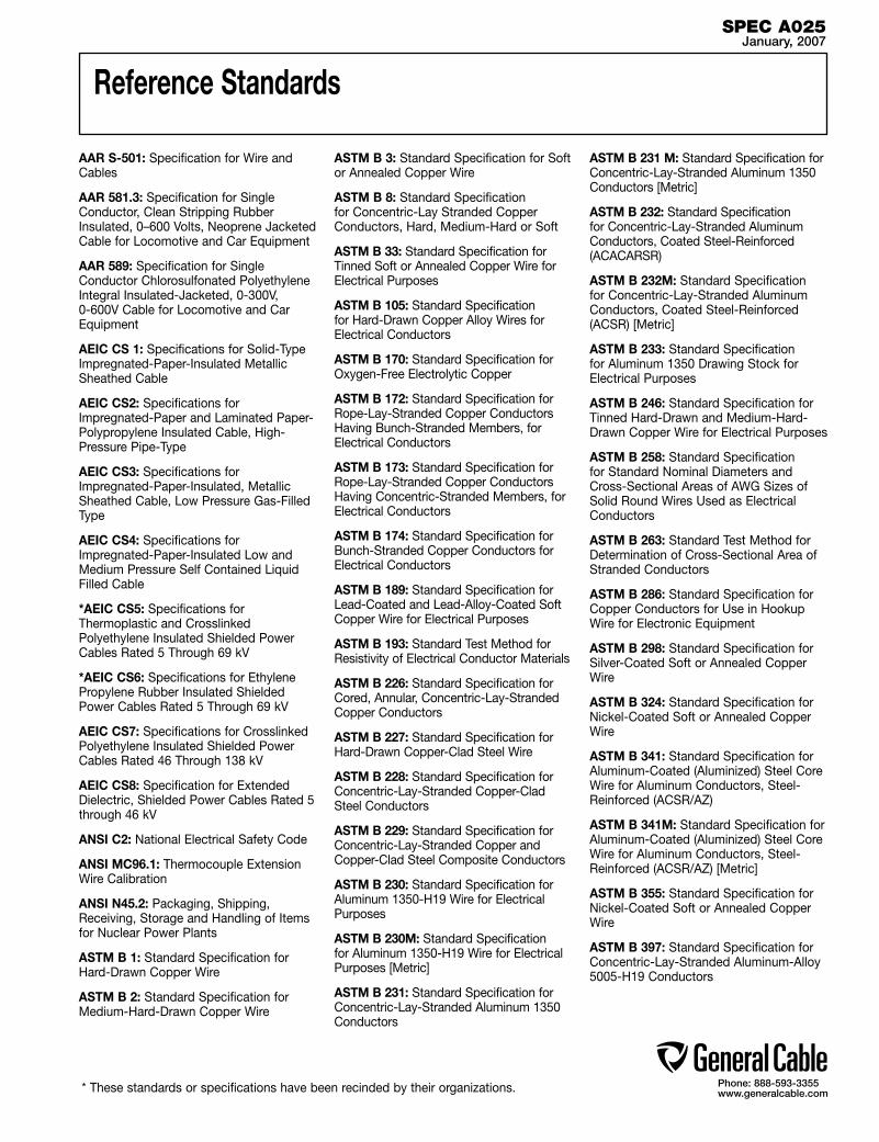
Phone: 888-593-3355www.generalcable.com
Reference Standards
AAR S-501: Specification for Wire and Cables
AAR 581.3: Specification for Single Conductor, Clean Stripping Rubber Insulated, 0–600 Volts, Neoprene Jacketed Cable for Locomotive and Car Equipment
AAR 589: Specification for Single Conductor Chlorosulfonated Polyethylene Integral Insulated-Jacketed, 0-300V, 0-600V Cable for Locomotive and Car Equipment
AEIC CS 1: Specifications for Solid-Type Impregnated-Paper-Insulated Metallic Sheathed Cable
AEIC CS2: Specifications for Impregnated-Paper and Laminated Paper-Polypropylene Insulated Cable, High-Pressure Pipe-Type
AEIC CS3: Specifications for Impregnated-Paper-Insulated, Metallic Sheathed Cable, Low Pressure Gas-Filled Type
AEIC CS4: Specifications for Impregnated-Paper-Insulated Low and Medium Pressure Self Contained Liquid Filled Cable
*AEIC CS5: Specifications for Thermoplastic and Crosslinked Polyethylene Insulated Shielded Power Cables Rated 5 Through 69 kV
*AEIC CS6: Specifications for Ethylene Propylene Rubber Insulated Shielded Power Cables Rated 5 Through 69 kV
AEIC CS7: Specifications for Crosslinked Polyethylene Insulated Shielded Power Cables Rated 46 Through 138 kV
AEIC CS8: Specification for Extended Dielectric, Shielded Power Cables Rated 5 through 46 kV
ANSI C2: National Electrical Safety Code
ANSI MC96.1: Thermocouple Extension Wire Calibration
ANSI N45.2: Packaging, Shipping, Receiving, Storage and Handling of Items for Nuclear Power Plants
ASTM B 1: Standard Specification for Hard-Drawn Copper Wire
ASTM B 2: Standard Specification for Medium-Hard-Drawn Copper Wire
ASTM B 3: Standard Specification for Soft or Annealed Copper Wire
ASTM B 8: Standard Specification for Concentric-Lay Stranded Copper Conductors, Hard, Medium-Hard or Soft
ASTM B 33: Standard Specification for Tinned Soft or Annealed Copper Wire for Electrical Purposes
ASTM B 105: Standard Specification for Hard-Drawn Copper Alloy Wires for Electrical Conductors
ASTM B 170: Standard Specification for Oxygen-Free Electrolytic Copper
ASTM B 172: Standard Specification for Rope-Lay-Stranded Copper Conductors Having Bunch-Stranded Members, for Electrical Conductors
ASTM B 173: Standard Specification for Rope-Lay-Stranded Copper Conductors Having Concentric-Stranded Members, for Electrical Conductors
ASTM B 174: Standard Specification for Bunch-Stranded Copper Conductors for Electrical Conductors
ASTM B 189: Standard Specification for Lead-Coated and Lead-Alloy-Coated Soft Copper Wire for Electrical Purposes
ASTM B 193: Standard Test Method for Resistivity of Electrical Conductor Materials
ASTM B 226: Standard Specification for Cored, Annular, Concentric-Lay-Stranded Copper Conductors
ASTM B 227: Standard Specification for Hard-Drawn Copper-Clad Steel Wire
ASTM B 228: Standard Specification for Concentric-Lay-Stranded Copper-Clad Steel Conductors
ASTM B 229: Standard Specification for Concentric-Lay-Stranded Copper and Copper-Clad Steel Composite Conductors
ASTM B 230: Standard Specification for Aluminum 1350-H19 Wire for Electrical Purposes
ASTM B 230M: Standard Specification for Aluminum 1350-H19 Wire for Electrical Purposes [Metric]
ASTM B 231: Standard Specification for Concentric-Lay-Stranded Aluminum 1350 Conductors
ASTM B 231 M: Standard Specification for Concentric-Lay-Stranded Aluminum 1350 Conductors [Metric]
ASTM B 232: Standard Specification for Concentric-Lay-Stranded Aluminum Conductors, Coated Steel-Reinforced (ACACARSR)
ASTM B 232M: Standard Specification for Concentric-Lay-Stranded Aluminum Conductors, Coated Steel-Reinforced (ACSR) [Metric]
ASTM B 233: Standard Specification for Aluminum 1350 Drawing Stock for Electrical Purposes
ASTM B 246: Standard Specification for Tinned Hard-Drawn and Medium-Hard-Drawn Copper Wire for Electrical Purposes
ASTM B 258: Standard Specification for Standard Nominal Diameters and Cross-Sectional Areas of AWG Sizes of Solid Round Wires Used as Electrical Conductors
ASTM B 263: Standard Test Method for Determination of Cross-Sectional Area of Stranded Conductors
ASTM B 286: Standard Specification for Copper Conductors for Use in Hookup Wire for Electronic Equipment
ASTM B 298: Standard Specification for Silver-Coated Soft or Annealed Copper Wire
ASTM B 324: Standard Specification for Nickel-Coated Soft or Annealed Copper Wire
ASTM B 341: Standard Specification for Aluminum-Coated (Aluminized) Steel Core Wire for Aluminum Conductors, Steel-Reinforced (ACSR/AZ)
ASTM B 341M: Standard Specification for Aluminum-Coated (Aluminized) Steel Core Wire for Aluminum Conductors, Steel-Reinforced (ACSR/AZ) [Metric]
ASTM B 355: Standard Specification for Nickel-Coated Soft or Annealed Copper Wire
ASTM B 397: Standard Specification for Concentric-Lay-Stranded Aluminum-Alloy 5005-H19 Conductors
SPEC A025January, 2007
* These standards or specifications have been recinded by their organizations.
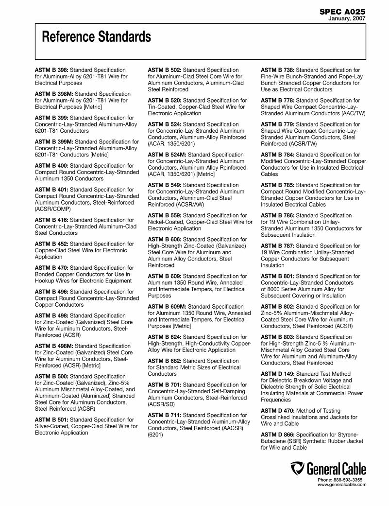
Phone: 888-593-3355www.generalcable.com
Reference Standards
ASTM B 398: Standard Specification for Aluminum-Alloy 6201-T81 Wire for Electrical Purposes
ASTM B 398M: Standard Specification for Aluminum-Alloy 6201-T81 Wire for Electrical Purposes [Metric]
ASTM B 399: Standard Specification for Concentric-Lay-Stranded Aluminum-Alloy 6201-T81 Conductors
ASTM B 399M: Standard Specification for Concentric-Lay-Stranded Aluminum-Alloy 6201-T81 Conductors [Metric]
ASTM B 400: Standard Specification for Compact Round Concentric-Lay-Stranded Aluminum 1350 Conductors
ASTM B 401: Standard Specification for Compact Round Concentric-Lay-Stranded Aluminum Conductors, Steel-Reinforced (ACSR/COMP)
ASTM B 416: Standard Specification for Concentric-Lay-Stranded Aluminum-Clad Steel Conductors
ASTM B 452: Standard Specification for Copper-Clad Steel Wire for Electronic Application
ASTM B 470: Standard Specification for Bonded Copper Conductors for Use in Hookup Wires for Electronic Equipment
ASTM B 496: Standard Specification for Compact Round Concentric-Lay-Stranded Copper Conductors
ASTM B 498: Standard Specification for Zinc-Coated (Galvanized) Steel Core Wire for Aluminum Conductors, Steel-Reinforced (ACSR)
ASTM B 498M: Standard Specification for Zinc-Coated (Galvanized) Steel Core Wire for Aluminum Conductors, Steel-Reinforced (ACSR) [Metric]
ASTM B 500: Standard Specification for Zinc-Coated (Galvanized), Zinc-5% Aluminum Mischmetal Alloy-Coated, and Aluminum-Coated (Aluminized) Stranded Steel Core for Aluminum Conductors, Steel-Reinforced (ACSR)
ASTM B 501: Standard Specification for Silver-Coated, Copper-Clad Steel Wire for Electronic Application
ASTM B 502: Standard Specification for Aluminum-Clad Steel Core Wire for Aluminum Conductors, Aluminum-Clad Steel Reinforced
ASTM B 520: Standard Specification for Tin-Coated, Copper-Clad Steel Wire for Electronic Application
ASTM B 524: Standard Specification for Concentric-Lay-Stranded Aluminum Conductors, Aluminum-Alloy Reinforced (ACAR, 1350/6201)
ASTM B 524M: Standard Specification for Concentric-Lay-Stranded Aluminum Conductors, Aluminum-Alloy Reinforced (ACAR, 1350/6201) [Metric]
ASTM B 549: Standard Specification for Concentric-Lay-Stranded Aluminum Conductors, Aluminum-Clad Steel Reinforced (ACSR/AW)
ASTM B 559: Standard Specification for Nickel-Coated, Copper-Clad Steel Wire for Electronic Application
ASTM B 606: Standard Specification for High-Strength Zinc-Coated (Galvanized) Steel Core Wire for Aluminum and Aluminum Alloy Conductors, Steel Reinforced
ASTM B 609: Standard Specification for Aluminum 1350 Round Wire, Annealed and Intermediate Tempers, for Electrical Purposes
ASTM B 609M: Standard Specification for Aluminum 1350 Round Wire, Annealed and Intermediate Tempers, for Electrical Purposes [Metric]
ASTM B 624: Standard Specification for High-Strength, High-Conductivity Copper-Alloy Wire for Electronic Application
ASTM B 682: Standard Specification for Standard Metric Sizes of Electrical Conductors
ASTM B 701: Standard Specification for Concentric-Lay-Stranded Self-Damping Aluminum Conductors, Steel-Reinforced (ACSR/SD)
ASTM B 711: Standard Specification for Concentric-Lay-Stranded Aluminum-Alloy Conductors, Steel Reinforced (AACSR) (6201)
ASTM B 738: Standard Specification for Fine-Wire Bunch-Stranded and Rope-Lay Bunch Stranded Copper Conductors for Use as Electrical Conductors
ASTM B 778: Standard Specification for Shaped Wire Compact Concentric-Lay-Stranded Aluminum Conductors (AAC/TW)
ASTM B 779: Standard Specification for Shaped Wire Compact Concentric-Lay-Stranded Aluminum Conductors, Steel Reinforced (ACSR/TW)
ASTM B 784: Standard Specification for Modified Concentric-Lay-Stranded Copper Conductors for Use in Insulated Electrical Cables
ASTM B 785: Standard Specification for Compact Round Modified Concentric-Lay-Stranded Copper Conductors for Use in Insulated Electrical Cables
ASTM B 786: Standard Specification for 19 Wire Combination Unilay-Stranded Aluminum 1350 Conductors for Subsequent Insulation
ASTM B 787: Standard Specification for 19 Wire Combination Unilay-Stranded Copper Conductors for Subsequent Insulation
ASTM B 801: Standard Specification for Concentric-Lay-Stranded Conductors of 8000 Series Aluminum Alloy for Subsequent Covering or Insulation
ASTM B 802: Standard Specification for Zinc-5% Aluminum-Mischmetal Alloy-Coated Steel Core Wire for Aluminum Conductors, Steel Reinforced (ACSR)
ASTM B 803: Standard Specification for High-Strength Zinc-5 % Aluminum-Mischmetal Alloy Coated Steel Core Wire for Aluminum and Aluminum-Alloy Conductors, Steel Reinforced
ASTM D 149: Standard Test Method for Dielectric Breakdown Voltage and Dielectric Strength of Solid Electrical Insulating Materials at Commercial Power Frequencies
ASTM D 470: Method of Testing Crosslinked Insulations and Jackets for Wire and Cable
ASTM D 866: Specification for Styrene-Butadiene (SBR) Synthetic Rubber Jacket for Wire and Cable
SPEC A025January, 2007

Phone: 888-593-3355www.generalcable.com
Reference Standards
ASTM D 1047: Specification for Polyvinyl Chloride (PVC) Jacket for Wire and Cable
ASTM D 1351: Specification for Polyethylene Insulation for Wire and Cable
ASTM D 1352: Specification for Ozone-Resisting Butyl Rubber Insulation for Wire and Cable
ASTM D 1523: Method for Synthetic Rubber Insulation for Wire and Cable, 90° Operation
ASTM D 1679: Specification for Synthetic Rubber Heat and Moisture-Resisting Insulation for Wire and Cable, 75°C Operation
ASTM D 2219: Specification for Polyvinyl Chloride (PVC) Insulation for Wire and Cable, 60° Operation
ASTM D 2220: Specification for Polyvinyl Chloride (PVC) Insulation for Wire and Cable, 75° Operation
ASTM D 2308: Specification for Polyethylene Jacket for Electrical Insulated Wire and Cable
ASTM D 2526: Specification for Ozone-Resisting Silicone Rubber Insulation for Wire and Cable
ASTM D 2655: Specification for Crosslinked Polyethylene Insulation for Wire and Cable Rated 0 to 2000V
ASTM D 2656: Specification for Crosslinked Polyethylene Insulation for Wire and Cable Rated 2001 to 35000V
ASTM D 2768: Specification for General-Purpose Ethylene-Propylene Rubber Jacket for Wire and Cable
ASTM D 2770: Specification for Ozone-Resisting Ethylene-Propylene Rubber Integral Insulation and Jacket for Wire and Cable
ASTM D 2802: Specification for Ozone-Resistant Ethylene-Propylene Rubber Insulation for Wire and Cable
ASTM D 3004: Specification for Extruded Thermosetting and Thermoplastic Semi-Conducting Conductor and Insulation Shields
ASTM D 3485: Specification for Smooth-Wall Coilable Polyethylene (PE) Conduit (Duct) for Preassembled Wire and Cable
ASTM D 3554: Specification for Track-Resistant Black Thermoplastic High Density Polyethylene Insulation for Wire and Cable
ASTM D 3555: Specification for Track-Resistant Black Crosslinked Thermosetting Polyethylene Insulation for Wire and Cable
ASTM D 4244: Specification for General-Purpose, Heavy-Duty and Extra-Heavy Duty Acrylonitrile-Butadiene/ Polyvinyl Chloride (NBR/PVC) Jackets for Wire and Cable
ASTM D 4245: Specification for Ozone-Resistant Thermoplastic Elastomer Insulation for Wire and Cable, 90°C Dry - 75°C Wet Operation
ASTM D 4246: Specification for Ozone-Resistant Thermoplastic Elastomer Insulation for Wire and Cable, 90°C Operation
ASTM D 4247: Specification for General-Purpose Black Heavy-Duty and Black Extra-Heavy Duty Polychloroprene Jackets for Wire and Cable
ASTM D 4313: Specification for General Purpose Heavy-Duty and Extra-Heavy-Duty Crosslinked Chlorinated Polyethylene Jackets for Wire and Cable
ASTM D 4314: Specification for General Purpose Heavy-Duty and Extra-Heavy-Duty Crosslinked Chlorosulfonated Poly-ethylene Jackets for Wire and Cable
ASTM D 4363: Specification for Thermoplastic Chlorinated Polyethylene Jacket for Wire and Cable
ASTM D 4496: Test Method of DC Resistance or Conductance of Moderately Conductive Materials
ASTM D 4568: Test Methods for Evaluating Compatibility Between Cable Filling and Flooding Compounds and Polyolefin Cable Materials
ASTM D 4967: Guide for Selecting Materials to Be Used for Insulation, Jacketing, and Strength Components in Fiber Optic Cables
CAN3-Z299.0: Guide for Selecting and Implementing the CAN3-Z299 Quality Assurance Program Standards
CAN3-Z299.1: Standard for Quality Assurance Program - Category 1
CAN3-Z299.2: Standard for Quality Assurance Program - Category 2
CAN3-Z299.3: Standard for Quality Assurance Program - Category 3
CAN3-Z299.4: Standard for Quality Assurance Program - Category 4
CAN/CSA C22.2 No. 211: Standard for Cord Sets and Power-Supply Cords
CAN/CSA C22.2 No. 48: Standard for Nonmetallic Sheathed Cable
CAN/CSA C22.2 No. 49: Standard for Flexible Cords and Cables
CAN/CSA C22.2 No. 51: Standard for Armored Cable
CAN/CSA C22.2 No. 96: Standard for Portable Power Cables
CAN/CSA C22.2 No. 130.1: Standard for Heat-Tracing Cable Systems for Use in Industrial Locations
CAN/CSA C22.2 No. 131: Standard for Type TECK 90 Cable
CAN/CSA C22.2 No. 203: Standard for Modular Wiring Systems for Office Furniture
CAN/CSA C22.2 No. 210.2: Standard for Appliance Wiring Material Products
CAN/CSA C22.2 No. 214: Standard for Communications Cables
CAN/CSA C22.2 No. 233: Standard for Cords and Cord Sets for Communication Systems
CAN/CSA C22.2 No. 239: Standard for Control and Instrumentation Cables
CAN/CSA C22.2 No. 241: IEEE Standard for Cable Joints for Use with Extruded Dielectric Cable Rated 5,000V Through 46,000V, and Cable Joints for Use with Laminated Dielectric Cable Rated 2,500V Through 500,000V (Adopted IEEE 404-1986)
CAN/CSA C22.3 No. 1: Standard for Overhead Systems
CAN/CSA C22.3 No. 8: Standard for Railway Electrification Guidelines
CAN/CSA C49.1: Standard for Round Wire, Concentric Lay, Overhead Electrical Conductors
SPEC A025January, 2007

Phone: 888-593-3355www.generalcable.com
Reference Standards
CAN/CSA C68.3: Standard for Shielded and Concentric Neutral Power Cables Rated 5-46 kV
CAN/CSA T529: Standard Design Guide for Telecommunications Wiring Systems in Commercial Buildings
CSA C22.1: Canadian Electrical Code, Part 1, Safety Standard for Electrical Installations
CSA C22.2 No. 0.3: Standard for Test Methods for Electrical Wires and Cables
CSA C22.2 No. 16: Standard for Insulated Conductors for Power-Operated Electronic Devices
CSA C22.2 No. 35: Standard for Extra-Low-Voltage Control Circuit Cables, Low-Energy Control Cable, and Extra-Low-Voltage Control Cable
CSA C22.2 No. 38: Standard for Thermoset Insulated Wires and Cables
CSA C22.2 No. 52: Standard for Service-Entrance Cables
CSA C22.2 No. 75: Standard for Thermoplastic-Insulated Wires and Cables
CSA C22.2 No. 116: Standard for Coil-Lead Wires
CSA C22.2 No. 123: Standard for Aluminum Sheathed Cables
CSA C22.2 No. 124: Standard for Mineral-Insulated Cable
CSA C22.2 No. 127: Standard for Equipment Wires
CSA C22.2 No. 129: Standard for Neutral Supported Cable
CSA C22.2 No. 130: Standard for Heating Cables and Heating Cable Sets
CSA C22.2 No. 138: Standard for Heat Tracing Cable and Cable Sets for Use in Hazardous Locations
CSA C22.2 No. 174: Standard for Cables and Cable Glands for Use in Hazardous Locations
CSA C22.2 No. 179: Standard for Airport Series Lighting Cables
CSA C22.2 No.188: Standard for Splicing Wire and Cable Connectors
CSA C22.2 No. 198.2: Standard for Underground Cable Splicing Kits
CSA C22.2 No. 208: Standard for Fire Alarm and Signal Cable
CSA C22.2 No. 222: Standard for Type FCC Under-Carpet Wiring System
CSA C22.2 No. 230: Standard for Tray Cable
CSA C22.2 No. 232: Standard for Optical Fiber Cables
CSA/CAN3 C22.3 No. 7: Standard for Underground Systems
CSA C49.2: Standard for Compact Aluminum Conductors Steel Reinforced (ACSR)
CSA C49.3: Standard for Aluminum Alloy 1350 Round Wire, All Tempers, for Electrical Purposes
CSA C49.4: Standard for Concentric-Lay Aluminum Stranded Conductors (ASC)
CSA C49.5: Standard for Compact Round Concentric-Lay Aluminum Stranded Conductors (Compact ASC)
CSA CAN3-C49.6: Standard for Zinc-Coated Steel Wires for Use in Overhead Electrical Conductors
CSA CAN3-C49.7: Standard for Aluminum Round Wires for Use in Overhead Electrical Conductors
CSA C68.1: Standard Specifications for Impregnated Paper-Insulated, Metallic-Sheathed Cable, Solid-Type
CSA C170.2: Standard for Polyethylene Protective Covering on Paper-Insulated Metallic Sheathed Power Cable
CSA C170.3: Standard for Polyvinyl-Chloride (PVC) Protective Covering on Paper-Insulated Metallic-Sheathed Power Cable
CSA M421: Standard for Use of Electricity in Mines
EIA/TIA-568: Commercial Building Telecommunications Wiring Standard
EIA/TIA-569: Commercial Building Standard for Telecommunications Pathways and Spaces
EIA/TIA-606: Administration Standard for the Telecommunications Infrastructure of Commercial Buildings
EIA/TIA TSB-36: Additional Cable Specifications for Unshielded Twisted Pair Cables (Technical Systems Bulletin 36)
EIA/TIA TSB-40: Additional Transmission Specifications for Unshielded Twisted Pair Connecting Hardware (Technical Systems Bulletin 40)
FP-4: TM-4 CSA CBC and UL CMR (Riser) Cable
FP-16: TD-16 Plastic Insulated, Two Parallel Conductor, Telephone Drop Wire
FP-28: Air Core, Solid PIC, ALPETH-DCAS Cable and PAP-DCAS Cable
FP-67: PHD Plastic Insulated and Jacketed, Four Conductor, Telephone Drop Wire
FP-68: TM-68 CSA PCC FT4, Shielded Inside Wiring Cable
FP-71: TM-28 CSA PCC FT4, Inside Wiring Cable
FP-75: PHILPLAST CSA PCC FT4, PVC Insulated and Jacketed, Switchboard Cable
FP-81: TM-81 CSA ZSW FT1, Telephone Station Wire
FP-90: CONCEL Cellular Polyethylene Insulated, Air Core, ALPETH-DCAS Sheathed, Telephone Cable
FP-93: TM-91, TM-92, TM-93 and TM-97, Filled, Buried Wire
FP-95: Quasi-Solid Polyethylene Insulated, Filled, Regular and Twin Core, ALPETH-DCAS Sheathed Cable
FP-98: CELSEAL Cellular Polyethylene Insulated, Filled, ALPETH-DCAS Sheathed Cable
FP-99: DUCTCEL Cellular Polyethylene Insulated, Air Core, ALPETH-DCAS Sheathed Telephone Cable
FP-8859: PHILSYM UL 444 CMR and CSA PCC FT4 Switchboard Cable
HP: See NEMA listing
ICEA P-32-382: ICEA Standards Publication for Short Circuit Characteristics of Insulated Cable
SPEC A025January, 2007

Phone: 888-593-3355www.generalcable.com
Reference Standards
ICEA P-45-482: ICEA Standards Publication for Short-Circuit Performance of Metallic Shields and Sheaths of Insulated Cable
ICEA P-53-426: ICEA/NEMA Standards Publication for Ampacities, Including Effect of Shield Losses for Single-Conductor Solid-Dielectric Power Cable 15 kV through 69 kV (NEMA WC 50)
ICEA P-54-440: ICEA/NEMA Standards Publication for Ampacities of Cables in Open-Top Cable Trays (NEMA WC 51)
ICEA P-79-561: ICEA Guide for Selecting Aerial Cable Messengers and Lashing Wires
ICEA S-56-434: ICEA/ANSI Standards Publication for Polyolefin Insulated Communications Cables for Outdoor Use
ICEA S-67-401: ICEA/NEMA Standards Publication for Steel Armor and Associated Coverings for Impregnated-Paper-Insulated Cables (NEMA WC 2)
ANSI/ICEA S-70-547: ICEA/ANSI Standards Publication for Weather-Resistant Polyolefin-Covered Wire and Cable
ICEA S-73-532: ICEA/NEMA/ANSI Standards Publication for Control Cables (NEMA WC 57)
ICEA S-75-381: ICEA/NEMA/ANSI Standards Publication for Portable and Power Feeder Cables for Use in Mines and Similar Applications (NEMA WC 58)
ANSI/ICEA S-76-474: ICEA/ANSI Standards Publication for Neutral-Supported Power Cable Assemblies with Weather-Resistant Extruded Insulation, 600 Volts
ICEA S-77-528: ICEA/ANSI Standards Publication for Outside Plant Communications Cables, Specifying Metric Wire Sizes
ICEA S-80-576: ICEA/ANSI Standards Publication for Communications Wire and Cable for Wiring of Premises
ANSI/ICEA S-81-570: Standard for 600 volt rated cables of Ruggedized Design For Direct Burial installations of single conductors or assemblies of single conductors.
ICEA S-82-552: ICEA/NEMA Standards Publication for Instrumentation Cables and Thermocouple Wire (NEMA WC 55)
ICEA S-83-596: ICEA/ANSI Standards Publication for Fiber Optic Premises Distribution Cable
ICEA S-84-608: ICEA/ANSI Standards Publication for Telecommunications Cable, Filled Polyolefin Insulated, Copper Conductor
ICEA S-85-625: ICEA/ANSI Standards Publication for Aircore, Polyolefin Insulated, Copper Conductor Telecommunications Cable
ICEA S-86-634: ICEA/ANSI Standards Publication for Buried Distribution and Service Wire, Filled Polyolefin Insulated, Copper Conductor
ICEA S-87-640: ICEA/ANSI Standards Publication for Fiber Optic Outside Plant Communication Cable
ICEA-S-93-639: ICEA/NEMA Standard for Shielded Power Cables Rated 5-46 KV for the Distribution of Electrical Energy (NEMA WC 74)
ANSI/ICEA-S-94-649: Standard for Concentric Neutral Cables Rated 5-46 KV
ICEA S-95-658: ICEA/NEMA Standard for Non-shielded Power Cables Rated 2000 Volts or Less for the Distribution of Electrical Energy (NEMA WC 70)
ICEA S-96-659: ICEA/NEMA Standard for Non-shielded Cables Rated 2001-5000 Volts for use in the Distribution of Electrical Energy (NEMA WC 71)
ANSI/ICEA S-97-682: Standard for Utility Shielded Power Cable Rated 5-46 KV
ANSI/ICEA S-105-692: Standard for 600 Volt Single Layer Thermoset Insulated Utility Underground Distribution Cable
ICEA T-22-294: ICEA Standard Test Procedures for Extended Time-Testing of Wire and Cable Insulations for Service in Wet Locations
ICEA T-25-425: ICEA Guide for Establishing Stability of Volume Resistivity for Conducting Polymeric Components of Power Cables
ICEA T-26-465: ICEA/NEMA Guide for Frequency of Sampling Extruded Dielectric Power, Control, Instrumentation and Port-able Cables for Test (NEMA WC 54)
ICEA T-27-581: ICEA/NEMA Standard Test Methods for Extruded Dielectric Power, Control, Instrumentation and Portable Cables (NEMA WC 53)
ANSI/ICEA T-28-562: ICEA Standard Test Method for Measurement of Hot Creep of Polymeric Insulations
ICEA T-29-520: ICEA Standard for Vertical Tray Flame Tests at 210,000 Btu
ICEA T-30-520: ICEA Standard for Vertical Tray Flame Tests at 70,000 Btu
ICEA T-31-610: ICEA Standard for Water Penetration Resistance Test, Sealed Conductor
ICEA T-32-645: ICEA Standards Publication for Compatibility of Sealed Conductor Filer Compounds
IEC 92-3: International Electrotechnical Commission Electrical Installation in Ships - Part 3 Cables (Constructions, Testing and Installations)
IEEE 45: IEEE Recommended Practice for Electric Installations on Shipboard
IEEE 48: IEEE Standard Test Procedures and Requirements for High-Voltage Alter-nating Current Cable Terminations
IEEE 100: IEEE Standard Dictionary of Electrical and Electronics Terms
IEEE 141: IEEE Recommended Practice for Electric Power Distribution for Industrial Plants (“IEEE Red Book”)
IEEE 142: IEEE Recommended Practice for Grounding of Industrial and Commercial Power Systems (“IEEE Green Book”)
IEEE 241: IEEE Recommended Practice for Electric Power Systems in Commercial Buildings (“IEEE Gray Book”)
IEEE 242: IEEE Recommended Practice for Protection and Coordination of Industrial and Commercial Power Systems (“IEEE Buff Book”)
IEEE 323: IEEE Standard for Qualifying Class 1E Equipment for Nuclear Power Generating Stations
IEEE 383: IEEE Standard for Type Test of Class 1E Electric Cables, Field Splices and Connections for Nuclear Power Generating Stations
SPEC A025January, 2007
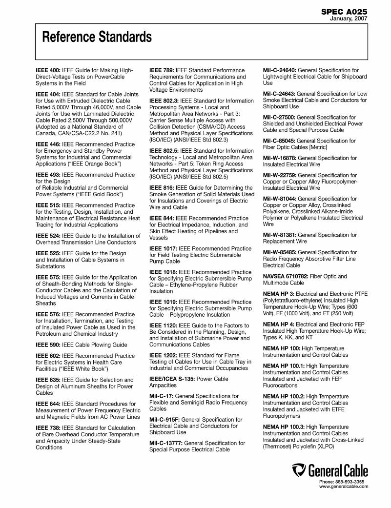
Phone: 888-593-3355www.generalcable.com
Reference Standards
IEEE 400: IEEE Guide for Making High-Direct-Voltage Tests on PowerCable Systems in the Field
IEEE 404: IEEE Standard for Cable Joints for Use with Extruded Dielectric Cable Rated 5,000V Through 46,000V, and Cable Joints for Use with Laminated Dielectric Cable Rated 2,500V Through 500,000V (Adopted as a National Standard of Canada, CAN/CSA-C22.2 No. 241)
IEEE 446: IEEE Recommended Practice for Emergency and Standby Power Systems for Industrial and Commercial Applications (“IEEE Orange Book”)
IEEE 493: IEEE Recommended Practice for the Design of Reliable Industrial and Commercial Power Systems (“IEEE Gold Book”)
IEEE 515: IEEE Recommended Practice for the Testing, Design, Installation, and Maintenance of Electrical Resistance Heat Tracing for Industrial Applications
IEEE 524: IEEE Guide to the Installation of Overhead Transmission Line Conductors
IEEE 525: IEEE Guide for the Design and Installation of Cable Systems in Substations
IEEE 575: IEEE Guide for the Application of Sheath-Bonding Methods for Single-Conductor Cables and the Calculation of Induced Voltages and Currents in Cable Sheaths
IEEE 576: IEEE Recommended Practice for Installation, Termination, and Testing of Insulated Power Cable as Used in the Petroleum and Chemical Industry
IEEE 590: IEEE Cable Plowing Guide
IEEE 602: IEEE Recommended Practice for Electric Systems in Health Care Facilities (“IEEE White Book”)
IEEE 635: IEEE Guide for Selection and Design of Aluminum Sheaths for Power Cables
IEEE 644: IEEE Standard Procedures for Measurement of Power Frequency Electric and Magnetic Fields from AC Power Lines
IEEE 738: IEEE Standard for Calculation of Bare Overhead Conductor Temperature and Ampacity Under Steady-State Conditions
IEEE 789: IEEE Standard Performance Requirements for Communications and Control Cables for Application in High Voltage Environments
IEEE 802.3: IEEE Standard for Information Processing Systems - Local and Metropolitan Area Networks - Part 3: Carrier Sense Multiple Access with Collision Detection (CSMA/CD) Access Method and Physical Layer Specifications (ISO/IEC) (ANSI/IEEE Std 802.3)
IEEE 802.5: IEEE Standard for Information Technology - Local and Metropolitan Area Networks - Part 5: Token Ring Access Method and Physical Layer Specifications (ISO/IEC) (ANSI/IEEE Std 802.5)
IEEE 816: IEEE Guide for Determining the Smoke Generation of Solid Materials Used for Insulations and Coverings of Electric Wire and Cable
IEEE 844: IEEE Recommended Practice for Electrical Impedance, Induction, and Skin Effect Heating of Pipelines and Vessels
IEEE 1017: IEEE Recommended Practice for Field Testing Electric Submersible Pump Cable
IEEE 1018: IEEE Recommended Practice for Specifying Electric Submersible Pump Cable – Ethylene-Propylene Rubber Insulation
IEEE 1019: IEEE Recommended Practice for Specifying Electric Submersible Pump Cable – Polypropylene Insulation
IEEE 1120: IEEE Guide to the Factors to Be Considered in the Planning, Design, and Installation of Submarine Power and Communications Cables
IEEE 1202: IEEE Standard for Flame Testing of Cables for Use in Cable Tray in Industrial and Commercial Occupancies
IEEE/ICEA S-135: Power Cable Ampacities
Mil-C-17: General Specifications for Flexible and Semirigid Radio Frequency Cables
Mil-C-915F: General Specification for Electrical Cable and Conductors for Shipboard Use
Mil-C-13777: General Specification for Special Purpose Electrical Cable
Mil-C-24640: General Specification for Lightweight Electrical Cable for Shipboard Use
Mil-C-24643: General Specification for Low Smoke Electrical Cable and Conductors for Shipboard Use
Mil-C-27500: General Specification for Shielded and Unshielded Electrical Power Cable and Special Purpose Cable
Mil-C-85045: General Specification for Fiber Optic Cables [Metric]
Mil-W-16878: General Specification for Insulated Electrical Wire
Mil-W-22759: General Specification for Copper or Copper Alloy Fluoropolymer-Insulated Electrical Wire
Mil-W-81044: General Specification for Copper or Copper Alloy, Crosslinked Polyalkene, Crosslinked Alkane-Imide Polymer or Polyalkene Insulated Electrical Wire
Mil-W-81381: General Specification for Replacement Wire
Mil-W-85485: General Specification for Radio Frequency Absorptive Filter Line Electrical Cable
NAVSEA 6710782: Fiber Optic and Multimode Cable
NEMA HP 3: Electrical and Electronic PTFE (Polytetrafluoro-ethylene) Insulated High Temperature Hook-Up Wire; Types (600 Volt), EE (1000 Volt), and ET (250 Volt)
NEMA HP 4: Electrical and Electronic FEP Insulated High Temperature Hook-Up Wire; Types K, KK, and KT
NEMA HP 100: High Temperature Instrumentation and Control Cables
NEMA HP 100.1: High Temperature Instrumentation and Control Cables Insulated and Jacketed with FEP Fluorocarbons
NEMA HP 100.2: High Temperature Instrumentation and Control Cables Insulated and Jacketed with ETFE Fluoropolymers
NEMA HP 100.3: High Temperature Instrumentation and Control Cables Insulated and Jacketed with Cross-Linked (Thermoset) Polyolefin (XLPO)
SPEC A025January, 2007

Phone: 888-593-3355www.generalcable.com
Reference Standards
NEMA HP 100.4: High Temperature Instrumentation and Control Cables Insulated and Jacketed with ECTFE Fluoropolymers
NEMA WC 2: Steel Armor and Associated Coverings for Impregnated-Paper-Insulated Cables (ICEA S-67-401)
NEMA WC 3: Rubber-Insulated Wire and Cable for the Transmission and Distribution of Electrical Energy (ICEA S-19-81)
NEMA WC 5: Thermoplastic-Insulated Wire and Cable for the Transmission and Distribution of Electrical Energy (ICEA S-61-402)
NEMA WC 7: Cross-Linked-Thermosetting-Polyethylene-Insulated Wire and Cable for the Transmission and Distribution of Electrical Energy (ICEA S-66-524)
NEMA WC 8: Ethylene-Propylene-Rubber-Insulated Wire and Cable for the Transmission and Distribution of Electrical Energy (ICEA S-68-516)
NEMA WC 26: Wire and Cable Packaging
NEMA WC 50: Ampacities, Including Effect of Shield Losses for Single-Conductor Solid Dielectric Power Cable 15 kV through 69 kV (ICEA P-53-426)
NEMA WC 51: Ampacities of Cables in Open-Top Cable Trays (ICEA P-54-440)
NEMA WC 52: High Temperature and Electronic Insulated Wire-Impulse Dielectric Testing
NEMA WC 53: Standard Test Methods for Extruded Dielectric Power, Control, Instru-mentation, and Portable Cables (ICEA T-27-581)
NEMA WC 54: Guide for Frequency of Sampling Extruded Dielectric Power, Control, Instrumentation, and Portable Cables for Test (ICEA T26-465)
NEMA WC 55: Instrumentation Cables and Thermocouple Wire (ICEA S-82-552)
NEMA WC 56: 3.0 kHz Insulation Continuity Proof Testing of Hook-Up Wire
NEMA WC 57: Standard for Control Cables (ICEA S-73-532)
NEMA WC 58: Standard for Portable and Power Feeder Cables for Use in Mines and Similar Applications (ICEA-S-75-381)
NEMA WC 61: Transfer Impedance Testing
NEMA WC 62: Repeated Spark/Impulse Dielectric Testing
NEMA WC 70: Standard for Non-shielded Power Cables Rated 2000 Volts or Less for the Distribution of Electrical Energy (ICEA S-95-658)
NEMA WC 71: Standard for Non-shielded Cables Rated 2001-5000 Volts for Use in the Distribution of Electrical Energy (ICEA S-96-659)
NEMA WC 74: Standard for Shielded Power Cables Rated 5-46 KV for the Distribution of Electrical Energy (ICEA S-93-639)
NFPA 70: National Electrical Code
NFPA 70HB: National Electrical Code Handbook
NFPA 262: Test for Fire and Smoke Characteristics of Wires and Cables
ONT M-302-84: Cable, Secondary, for Direct Burial
ONT M-355-82: Cable, Primary Submarine
ONT M-538-84: Cable, For Use in Generating Stations (5 kV and Above)
ONT M-570-84: Cable, For Use in Generating Stations (600V)
ONT M-695-88: Cable, Primary and Subtransmission Submarine, Concentric Neutral
SAE 1560: Low Tension, Thin Wall Primary Cable
SAE J1127: Battery Cable
SAE J1128: Low Tension Primary Cable
TIA: See EIA/TIA
UL 4: Standard for Armored Cable
UL 13: Standard for Power-Limited Circuit Cables
UL 44: Standard for Rubber-Insulated Wires and Cables
UL 62: Standard for Flexible Cord and Fixture Wire
UL 83: Standard for Thermoplastic-Insulated Wires and Cables
UL 183: Standard for Manufactured Wiring Systems
UL 444: Standard for Communications Cables
UL 486A: Standard for Wire Connectors and Soldering Lugs for Use With Copper Conductors
UL 486B: Standard for Wire Connectors and Soldering Lugs for Use With Aluminum Conductors
UL 486C: Standard for Splicing Wire Connectors
UL 486D: Standard for Insulated Wire Connectors for Use With Underground Conductors
UL 486E: Standard for Equipment Wiring Terminals for Use With Aluminum and/or Copper Conductors
UL 493: Standard for Thermoplastic-Insulated Underground Feeder and Branch-Circuit Cables
UL 498: Standard for Attachment Plugs and Receptacles
UL 514B: Standard for Fittings for Conduit and Outlet Boxes
UL 719: Standard for Nonmetallic-Sheathed Cables
UL 758: Standard for Appliance Wiring Material - Component
UL 814: Standard for Gas-Tube-Sign and Ignition Cable
UL 817: Standard for Cord Sets and Power-Supply Cords
UL 854: Standard for Service-Entrance Cables
UL 910: Standard for Test for Flame-Propagation and Smoke-Density Values for Electrical and Optical-Fiber Cables Used in Spaces Transporting Environmental Air
UL 1023: Standard for Household Burglar-Alarm System Units
UL 1063: Standard for Machine-Tool Wires and Cables
UL 1072: Standard for Medium-Voltage Power Cables
UL 1084: Standard for Hoistway Cables
UL 1263: Standard for Irrigation Cables
SPEC A025January, 2007

Phone: 888-593-3355www.generalcable.com
Reference Standards
UL 1277: Standard for Electrical Power and Control Tray Cables With Optional Optical Fiber Members
UL 1309: Standard for Marine Shipboard Cable
UL 1424: Standard for Cables for Power-Limited Fire-Protective-Signaling Circuits
UL 1426: Standard for Cables for Boats
UL 1446: Standard for Systems of Insulating Materials—General
UL 1462: Standard for Mobile Home Pipe Heating Cable
UL 1569: Standard for Metal-Clad Cables
UL 1581: Reference Standard for Electrical Wires, Cables and Flexible Cords
UL 1588: Standard for Roof and Gutter De-Icing Cable Units
UL 1666: Standard Test for Flame Propagation Height of Electrical and Optical-Fiber Cables Installed Vertically in Shafts
UL 1673: Standard for Electric Space Heating Cables
UL 1685: Standard for Vertical-Tray Fire-Propagation and Smoke-Release Test for Electrical and Optical-Fiber Cables
UL 1690: Standard for Data Processing (DP) Cables
UL 1712: Standard Tests for Ampacity of Insulated Electrical Conductors Installed in the Fire Protective System
UL 1807: Standard for Fire Resistant Cable Coating Materials
UL 2023: Standard Test Method for Flame and Smoke Characteristics of Nonmetallic Wiring Systems (Raceway and Conductors) for Environmental Air-Handling Spaces
UL 2029: Standard for Gas/Vapor-Blocked Cable Classified for Use in Class 1
Hazardous (Classified) Locations
UL 2049: Standard for Residential Pipe Heating Cable
WC: See NEMA listing
SPEC A025January, 2007
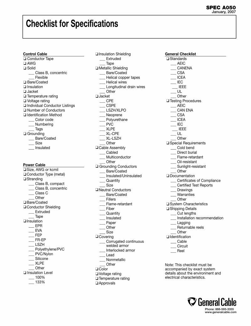
Phone: 888-593-3355www.generalcable.com
Control Cable Conductor Tape AWG Solid ___ Class B, concentric ___ Flexible Bare/Coated Insulation Jacket Temperature rating Voltage rating Individual Conductor Listings Number of Conductors Identification Method ___ Color code ___ Numbering ___ Tags Grounding ___ Bare/Coated ___ Size ___ Insulated Power Cable Size, AWG or kcmil Conductor Type (metal) Stranding ___ Class B, compact ___ Class B, concentric ___ Class C ___ Other Bare/Coated Conductor Shielding ___ Extruded ___ Tape Insulation ___ EPR ___ EVA ___ FEP ___ FR-EP ___ LSZH ___ Polyethylene/PVC ___ PVC/Nylon ___ Silicone ___ XLPE ___ Other Insulation Level ___ 100% ___ 133%
Insulation Shielding ___ Extruded ___ Tape Metallic Shielding ___ Bare/Coated ___ Helical copper tapes ___ Helical wires ___ Longitudinal drain wires ___ Other Jacket ___ CPE ___ CSPE ___ LSZH/XLPO ___ Neoprene ___ Polyurethane ___ PVC ___ XLPE ___ XL-CPE ___ XL-LSZH ___ Other Cable Assembly ___ Cabled ___ Multiconductor ___ Other Grounding Conductors ___ Bare/Coated ___ Insulated/Uninsulated ___ Quantity ___ Size Neutral Conductors ___ Bare/Coated ___ Fillers ___ Flame-retardant ___ Fiber ___ Quantity ___ Insulated ___ Paper ___ Other ___ Size Covering ___ Corrugated continuous
welded armor ___ Interlocked armor ___ Lead ___ Nonmetallic ___ Other Color Voltage rating Temperature rating Approvals
General Checklist Standards ___ AEIC ___ CANENA ___ CSA ___ ICEA ___ IEC ___ IEEE ___ UL ___ Other Testing Procedures ___ AEIC ___ CAN ENA ___ CSA ___ ICEA ___ IEC ___ IEEE ___ UL ___ Other Special Requirements ___ Cold bend ___ Direct burial ___ Flame-retardant ___ Oil-resistant ___ Sunlight-resistant ___ Other Documentation ___ Certificates of Compliance ___ Certified Test Reports ___ Drawings ___ Warranties ___ Other System Characteristics Shipping Details ___ Cut lengths ___ Installation recommendation ___ Lagging ___ Returnable reels ___ Other Identification ___ Cable ___ Circuit ___ Reel
Note: This checklist must be accompanied by exact system details about the environment and electrical characteristics.
Checklist for Specifications
SPEC A050January, 2007

Phone: 888-593-3355www.generalcable.com
AWMMV-HLITCMV-LSMCMTWMV-90MV-105PLTCRHHRHW-2SF-2SFF-2SISTCTFFNTFNTHHNTHWNUSE-2XHHW-2
NEC and CSA Designations
Appliance Wiring Material, Thermoplastic Insulation (PVC), With or Without Nylon, 105˚C, Dry Locations
Suffix “-HL” Indicates Acceptable for Hazardous Locations
Instrumentation Tray Cable, Several Combinations for Insulations and Jacket Compounds
Suffix “-LS” Indicates Acceptable for Limited Smoke Applications
Metal Clad Cable, THHN or XHHW Individual Conductors, Aluminum or Steel Interlocked Armor
Machine Tool Wire, Thermoplastic Insulation (PVC), With or Without Nylon, 90˚C, Dry Locations
Medium Voltage Cable Rated at 90˚C
Medium Voltage Cable Rated at 105˚C
Power-Limited Tray Cable, Several Combinations of Insulations and Jacket Compounds
Rubber Equivalent Insulation (XLPE), High Heat Resistant 90˚C Rating, Dry or Damp Locations
Rubber Equivalent Insulation (XLPE), Heat Resistant 90˚C Rating, Wet Locations
Silicone Insulated Fixture Wire, Solid or 2-Strand
Silicone Insulated Fixture Wire, Flexible Strand
Flame-Retardant Thermoset Switchboard Wire
Tray Cable, Several Combinations of Insulation and Jacket Compounds, Cable Tray Use
Thermoplastic Insulation (PVC), Flexible Fixture Wire, 90˚C, Dry Locations, Nylon Jacket
Thermoplastic Insulation (PVC), Fixture Wire, 90˚C, Dry Locations, Nylon Jacket
Thermoplastic Insulation (PVC), High Heat Resistant, 90˚C Rating, Dry or Damp Locations, Nylon Jacket
Thermoplastic Insulation (PVC), Heat Resistant 75˚C Rating, Wet Locations, Nylon Jacket
Underground Service Entrance, Cross-Linked Polyethylene Insulation (XLPE), Direct Burial, 90˚C Rating
Cross-Linked Polyethylene Insulation (XLPE), High Heat Resistant 90˚C Rating, Wet and Dry Locations
NEC WIRETYPE DESCRIPTION
AC90 ACIC
ACWU90 (-40˚C) HL (Hazardous Locations)
NMD90 NMWU RA90 (-40˚C)
RW90 XLPE (-40˚C)
RWU90 XLPE (-40˚C)
SEW-2 SEWF-2 TECK90 (-40˚C) TC TW75 TWU (-40˚C)
600 Volt XLPE Insulation Aluminum or Steel Interlocked Armored Cable300 or 600 Volt Armored Instrument and Control Cable. A CSA-type designation used to describe Armored Instrumentation and Control Cable. Available in either 300 Volt or 600 Volt with thermoset or thermoplastic insulation, this cable can be supplied with an overall shield, shielded pairs, shielded triads or unshielded in multi-conductor constructions from 2 to 72 conductors. The overall interlocked armor and PVC jacket provide a (-40˚C), HL, FT4 product (CSA reference standard C22.2 No. 239)600 Volt XLPE Insulation Aluminum or Steel Interlocked Armored Cable with PVC jacket
Designation for Hazardous Locations (CSA STD C22.2 NO174)
300 Volt Non-Metallic Sheath Cable with XLPE or PVC/Nylon Insulation
300 Volt Non-Metallic Sheath Cable with PVC Insulation600 and 5000 Volt Single and Multiple Conductor with Seamless Corrugated Aluminum Armor. A CSA-type designation for single- conductor or multi-conductor constructions similar to AC90 and ACWU90 except no bonding (grounding) conductor is required in the cable assembly. Also the armor is a corrugated aluminum sheath which serves as a bonding (grounding) conductor. The overall PVC covering on RA90 is required for wet or direct burial applications (CSA reference standard C22.2 No. 123) 600 and 5000 Volt Thermoset Insulation 90˚C Wet or Dry Locations
600 and 1000 Volt Thermoset Insulation 90˚C Direct Burial
600 Volt Silicone Rubber Insulated Equipment Wire Solid or 7-Strand
600 Volt Silicone Rubber Insulated Equipment Wire with Flexible Strand
600 and 5000 Volt Single and Multiple Conductor Cable with Inner Jacket, Aluminum or Steel Interlocked Armor with PVC Jacket
Tray Cable Certified for Use in Class 1 Division 2 Areas
600 Volt Thermoplastic (PVC) Insulated Cable Suitable for Wet Locations
600 Volt Thermoplastic (PVC) Insulated Cable Suitable for Direct Burial
CSA WIRETYPE
DESCRIPTION
SPEC A075January, 2007
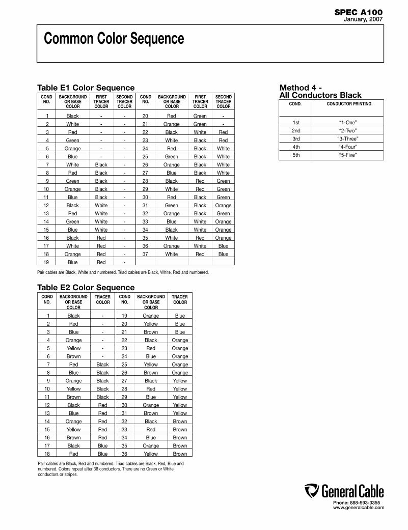
Phone: 888-593-3355www.generalcable.com
Common Color Sequence
1 Black - -
2 White - -
3 Red - -
4 Green - -
5 Orange - -
6 Blue - -
7 White Black -
8 Red Black -
9 Green Black -
10 Orange Black -
11 Blue Black -
12 Black White -
13 Red White -
14 Green White -
15 Blue White -
16 Black Red -
17 White Red -
18 Orange Red -
19 Blue Red -
20 Red Green -
21 Orange Green -
22 Black White Red
23 White Black Red
24 Red Black White
25 Green Black White
26 Orange Black White
27 Blue Black White
28 Black Red Green
29 White Red Green
30 Red Black Green
31 Green Black Orange
32 Orange Black Green
33 Blue White Orange
34 Black White Orange
35 White Red Orange
36 Orange White Blue
37 White Red Blue
COND. CONDUCTOR PRINTING
1st “1-One”
2nd “2-Two”
3rd “3-Three”
4th “4-Four”
5th “5-Five”
Table E1 Color Sequence Method 4 - All Conductors Black
Pair cables are Black, White and numbered. Triad cables are Black, White, Red and numbered.
1 Black -
2 Red -
3 Blue -
4 Orange -
5 Yellow -
6 Brown -
7 Red Black
8 Blue Black
9 Orange Black
10 Yellow Black
11 Brown Black
12 Black Red
13 Blue Red
14 Orange Red
15 Yellow Red
16 Brown Red
17 Black Blue
18 Red Blue
19 Orange Blue
20 Yellow Blue
21 Brown Blue
22 Black Orange
23 Red Orange
24 Blue Orange
25 Yellow Orange
26 Brown Orange
27 Black Yellow
28 Red Yellow
29 Blue Yellow
30 Orange Yellow
31 Brown Yellow
32 Black Brown
33 Red Brown
34 Blue Brown
35 Orange Brown
36 Yellow Brown
Table E2 Color Sequence
Pair cables are Black, Red and numbered. Triad cables are Black, Red, Blue and numbered. Colors repeat after 36 conductors. There are no Green or White conductors or stripes.
COND NO.
BACKGROUNDOR BASECOLOR
FIRSTTRACERCOLOR
SECONDTRACERCOLOR
COND NO.
BACKGROUNDOR BASECOLOR
SECONDTRACERCOLOR
COND NO.
BACKGROUNDOR BASECOLOR
TRACER COLOR
COND NO.
BACKGROUNDOR BASECOLOR
TRACER COLOR
SPEC A100January, 2007
FIRSTTRACERCOLOR
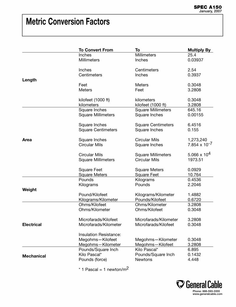
Phone: 888-593-3355www.generalcable.com
Metric Conversion Factors
To Convert From To Multiply By Inches Millimeters 25.4 Millimeters Inches 0.03937
Inches Centimeters 2.54 Centimeters Inches 0.3937Length Feet Meters 0.3048 Meters Feet 3.2808
kilofeet (1000 ft) kilometers 0.3048 kilometers kilofeet (1000 ft) 3.2808 Square Inches Square Millimeters 645.16 Square Millimeters Square Inches 0.00155
Square Inches Square Centimeters 6.4516 Square Centimeters Square Inches 0.155
Area Square Inches Circular Mils 1,273,240 Circular Mils Square Inches 7.854 x 10⁻⁷
Circular Mils Square Millimeters 5.066 x 10⁴
Square Millimeters Circular Mils 1973.51
Square Feet Square Meters 0.0929 Square Meters Square Feet 10.764 Pounds Kilograms 0.4536 Kilograms Pounds 2.2046Weight Pound/Kilofeet Kilograms/Kilometer 1.4882 Kilograms/Kilometer Pounds/Kilofeet 0.6720 Ohms/Kilofeet Ohms/Kilometer 3.2808 Ohms/Kilometer Ohms/Kilofeet 0.3048
Microfarads/Kilofeet Microfarads/Kilometer 3.2808Electrical Microfarads/Kilometer Microfarads/Kilofeet 0.3048
Insulation Resistance: Megohms—Kilofeet Megohms—Kilometer 0.3048 Megohms—Kilometer Megohms—Kilofeet 3.2808 Pounds/Square Inch Kilo Pascal* 6.895
Mechanical Kilo Pascal* Pounds/Square Inch 0.1432 Pounds (force) Newtons 4.448 * 1 Pascal = 1 newton/m2
SPEC A150January, 2007

Reel Capacity Chart
SPEC A200January, 2007
WOOD REELS36x24x1761-1659
3.06162
1155.4150091
10790101109610903084908100762073006880660062306000566054505250497047004630439040403650331030802810263024002260207019501840169016101530145013401280122011701075990910810750700650580550520490410370330
Reel (FxTxB)RM Code
Arbor HoleDrive Hole
Drive Hole RadiusClearance
Factor Max WeightNet WeightCable OD.241 - .250.251 - .260.261 - .270.271 - .280.281 - .290.291 - .300.301 - .310.311 - .320 .321 - .330.331 - .340.341 - .350.351 - .360.361 - .370.371 - .380.381 - .390.391 - .400.401 - .410.411 - .420.421 - .430.431 - .440.441 - .450.451 - .460.461 - .470.471 - .480.481 - .490.491 - .500.501 - .525.526 - .550.551 - .575.576 - .600.601 - .625.626 - .650.651 - .675.676 - .700.701 - .725.726 - .750.751 - .775.776 - .800.801 - .825.826 - .850.851 - .875.876 - .900.901 - .925.926 - .950.951 - .975.976 - 1.000
1.001 - 1.0501.051 - 1.1001.101 - 1.1501.151 - 1.2001.201 - 1.2501.251 - 1.3001.301 - 1.3501.351 - 1.4001.401 - 1.4501.451 - 1.5001.501 - 1.6001.601 - 1.7001.701 - 1.8001.801 - 1.9001.091 - 2.0002.001 - 2.1002.101 - 2.2002.201 - 2.3002.301 - 2.4002.401 - 2.5002.501 - 2.6002.601 - 2.7002.701 - 2.8002.801 - 2.9002.901 - 3.0003.001 - 3.1003.101 - 3.2003.201 - 3.3003.301 - 3.4003.401 - 3.500
30x18x1261-1215
2.751
4.51.5
509.375047
11040102009460880082007660718067406330597056306320504047804530431041003910373035603410326031202990287027602500228020901920177016301510141013101230115010801010950900850810760730690630570520480440410380350330310270240
40x24x1761-1808
3.06162
1582.82000110
10520994095409030855082207790751071206880653063106110553050304580418039103580328030902840269024802350223020601970188017351660159015251360126011201040980870820770690650590500450420
50x32x2461-2253
3.061.5102
3227.74800208
15010142901379013150127001154010510961088008050743069706430594056105190492046704340413038503670351032703130288025902400216020201820171016101460137012301060960880760700650600520490460430
58x32x2861-2764
3.061.5102
4468.66500271
1042096308900826078007250687064006090568054205060484046304340399036003250303027402570241021902070195016901520132512101060970900790740690640600530500470440420400380
72x36x3661-3655
3.061.5102
7847.48000513
1153010860102509690917087008250785071206490593054505020464043204000373034903070272024202170196017401620148013601260116010801000930870820770720680640
84x36x4861-4265
3.51.5102
9658.49000744
112901070010160966087607980730067106180572053004930459042903770334029802680241021902000183016801550143013201230115010701010940890840790
90x36x4861-4366
3.51.5103
11205.210,000
821
1121010160926084707780717066306150572053304980438038803460310028002540232021201950179016601540143013301250117010901030970910
Phone: 888-593-3355www.generalcable.com
45x28x2161-2056
3.061.58.52
2274.23000142
12580119401133010910103701000095109180888080507330668061105590524048204530418039503650346032003040290026902570246022802190201018001670150014001310118011101040990840760650600540500
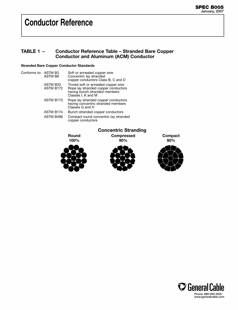
Phone: 888-593-3355www.generalcable.com
Conductor Reference
Concentric Stranding
TABLE 1 – Conductor Reference Table – Stranded Bare Copper Conductor and Aluminum (ACM) Conductor
Stranded Bare Copper Conductor Standards
Conforms to: ASTM B3 Soft or annealed copper wire ASTM B8 Concentric lay stranded copper conductors Class B, C and D ASTM B33 Tinned soft or annealed copper wire ASTM B172 Rope lay stranded copper conductors having bunch stranded members Classes I, K and M ASTM B173 Rope lay stranded copper conductors having concentric stranded members Classes G and H ASTM B174 Bunch stranded copper conductors ASTM B496 Compact round concentric lay stranded copper conductors
SPEC B005January, 2007
Round100%
Compressed90%
Compact90%
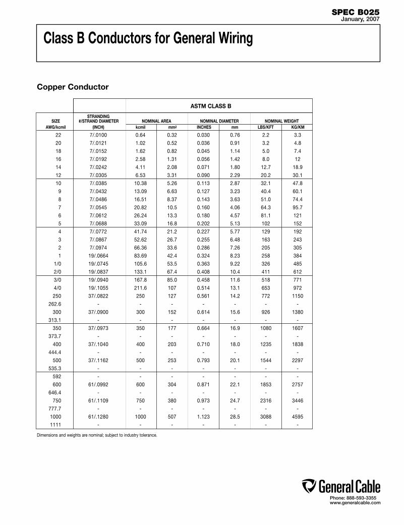
Phone: 888-593-3355www.generalcable.com
Class B Conductors for General Wiring
STRANDING SIZE #/STRAND DIAMETER NOMINAL AREA NOMINAL DIAMETER NOMINAL WEIGHT AWG/kcmil (INCH) kcmil mm2 INCHES mm LBS/KFT KG/KM
22 7/.0100 0.64 0.32 0.030 0.76 2.2 3.3
20 7/.0121 1.02 0.52 0.036 0.91 3.2 4.8
18 7/.0152 1.62 0.82 0.045 1.14 5.0 7.4
16 7/.0192 2.58 1.31 0.056 1.42 8.0 12
14 7/.0242 4.11 2.08 0.071 1.80 12.7 18.9
12 7/.0305 6.53 3.31 0.090 2.29 20.2 30.1
10 7/.0385 10.38 5.26 0.113 2.87 32.1 47.8
9 7/.0432 13.09 6.63 0.127 3.23 40.4 60.1
8 7/.0486 16.51 8.37 0.143 3.63 51.0 74.4
7 7/.0545 20.82 10.5 0.160 4.06 64.3 95.7
6 7/.0612 26.24 13.3 0.180 4.57 81.1 121
5 7/.0688 33.09 16.8 0.202 5.13 102 152
4 7/.0772 41.74 21.2 0.227 5.77 129 192
3 7/.0867 52.62 26.7 0.255 6.48 163 243
2 7/.0974 66.36 33.6 0.286 7.26 205 305
1 19/.0664 83.69 42.4 0.324 8.23 258 384
1/0 19/.0745 105.6 53.5 0.363 9.22 326 485
2/0 19/.0837 133.1 67.4 0.408 10.4 411 612
3/0 19/.0940 167.8 85.0 0.458 11.6 518 771
4/0 19/.1055 211.6 107 0.514 13.1 653 972
250 37/.0822 250 127 0.561 14.2 772 1150
262.6 - - - - - - -
300 37/.0900 300 152 0.614 15.6 926 1380
313.1 - - - - - - -
350 37/.0973 350 177 0.664 16.9 1080 1607
373.7 - - - - - - -
400 37/.1040 400 203 0.710 18.0 1235 1838
444.4 - - - - - - -
500 37/.1162 500 253 0.793 20.1 1544 2297
535.3 - - - - - - -
592 - - - - - - -
600 61/.0992 600 304 0.871 22.1 1853 2757
646.4 - - - - - - -
750 61/.1109 750 380 0.973 24.7 2316 3446
777.7 - - - - - - -
1000 61/.1280 1000 507 1.123 28.5 3088 4595
1111 - - - - - - -
ASTM CLASS B
Copper Conductor
Dimensions and weights are nominal; subject to industry tolerance.
SPEC B025January, 2007

Phone: 888-593-3355www.generalcable.com
Class C Conductors for General Wiring
Copper Conductor
Dimensions and weights are nominal; subject to industry tolerance.
SPEC B030January, 2007
ASTM CLASS C
STRANDING SIZE #/STRAND DIAMETER NOMINAL AREA NOMINAL DIAMETER NOMINAL WEIGHT AWG/kcmil (INCH) kcmil mm2 INCHES mm LBS/KFT KG/KM
22 19/.0063 0.64 0.32 0.031 0.79 2.3 3.4
20 19/.0080 1.02 0.52 0.038 0.97 3.8 5.7
18 19/.0092 1.62 0.82 0.044 1.12 5.0 7.4
16 19/.0117 2.58 1.31 0.056 1.42 8.0 12
14 19/.0147 4.11 2.08 0.071 1.80 12.7 18.9
12 19/.0185 6.53 3.31 0.089 2.26 20.2 30.1
10 19/.0234 10.38 5.26 0.112 2.85 32.1 47.8
9 19/.0262 13.09 6.63 0.123 3.12 40.4 60.1
8 19/.0295 16.51 8.37 0.139 3.53 51.0 74.4
7 19/.0331 20.82 10.5 0.156 3.96 64.3 95.7
6 19/.0372 26.24 13.3 0.175 4.45 81.0 121
5 19/.0417 33.09 16.8 0.203 5.16 102 152
4 19/.0469 41.74 21.2 0.229 5.82 129 192
3 19/.0526 52.62 26.7 0.256 6.50 163 243
2 19/.0591 66.36 33.6 0.288 7.32 205 305
1 37/.0476 83.69 42.4 0.325 8.26 258 384
1/0 37/.0534 105.6 53.5 0.364 9.25 326 485
2/0 37/.0600 133.1 67.4 0.410 10.4 411 612
3/0 37/.0673 167.8 85.0 0.459 11.7 518 771
4/0 37/.0756 211.6 107 0.516 13.1 653 972
250 61/.0640 250 127 0.562 14.3 774 1150
262.6 - - - - - - -
300 61/.0701 300 152 0.615 15.6 927 1380
313.1 - - - - - - -
350 61/.0757 350 177 0.664 16.9 1082 1610
373.7 - - - - - - -
400 61/.0810 400 203 0.711 18.1 1235 1838
444.4 - - - - - - -
500 61/.0905 500 253 0.794 20.2 1545 2299
535.3 - - - - - - -
592 - - - - - - -
600 91/.0812 600 304 0.893 22.7 1853 2757
646.4 - - - - - - -
750 91/.0908 750 380 0.999 25.4 2316 3446
777.7 - - - - - - -
1000 91/.1048 1000 507 1.153 29.3 3088 4595
1111 - - - - - - -
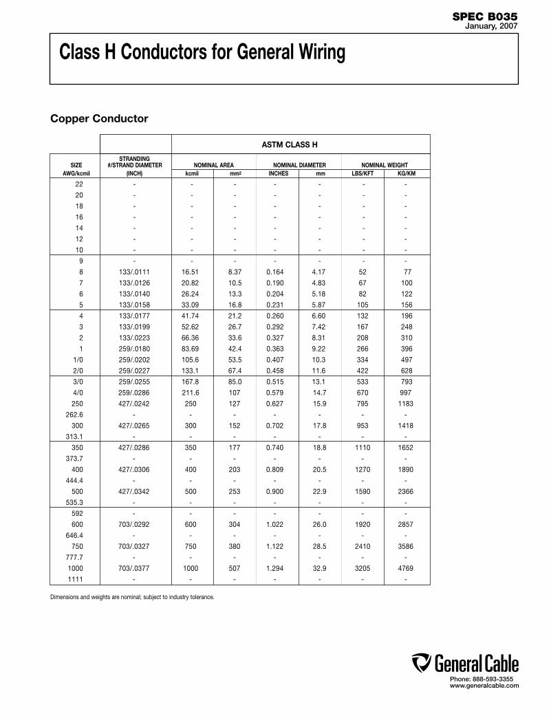
Phone: 888-593-3355www.generalcable.com
STRANDING SIZE #/STRAND DIAMETER NOMINAL AREA NOMINAL DIAMETER NOMINAL WEIGHT AWG/kcmil (INCH) kcmil mm2 INCHES mm LBS/KFT KG/KM
22 - - - - - - -
20 - - - - - - -
18 - - - - - - -
16 - - - - - - -
14 - - - - - - -
12 - - - - - - -
10 - - - - - - -
9 - - - - - - -
8 133/.0111 16.51 8.37 0.164 4.17 52 77
7 133/.0126 20.82 10.5 0.190 4.83 67 100
6 133/.0140 26.24 13.3 0.204 5.18 82 122
5 133/.0158 33.09 16.8 0.231 5.87 105 156
4 133/.0177 41.74 21.2 0.260 6.60 132 196
3 133/.0199 52.62 26.7 0.292 7.42 167 248
2 133/.0223 66.36 33.6 0.327 8.31 208 310
1 259/.0180 83.69 42.4 0.363 9.22 266 396
1/0 259/.0202 105.6 53.5 0.407 10.3 334 497
2/0 259/.0227 133.1 67.4 0.458 11.6 422 628
3/0 259/.0255 167.8 85.0 0.515 13.1 533 793
4/0 259/.0286 211.6 107 0.579 14.7 670 997
250 427/.0242 250 127 0.627 15.9 795 1183
262.6 - - - - - - -
300 427/.0265 300 152 0.702 17.8 953 1418
313.1 - - - - - - -
350 427/.0286 350 177 0.740 18.8 1110 1652
373.7 - - - - - - -
400 427/.0306 400 203 0.809 20.5 1270 1890
444.4 - - - - - - -
500 427/.0342 500 253 0.900 22.9 1590 2366
535.3 - - - - - - -
592 - - - - - - -
600 703/.0292 600 304 1.022 26.0 1920 2857
646.4 - - - - - - -
750 703/.0327 750 380 1.122 28.5 2410 3586
777.7 - - - - - - -
1000 703/.0377 1000 507 1.294 32.9 3205 4769
1111 - - - - - - -
Class H Conductors for General Wiring
Copper Conductor
Dimensions and weights are nominal; subject to industry tolerance.
SPEC B035January, 2007
ASTM CLASS H

Phone: 888-593-3355www.generalcable.com
Class I Conductors for General Wiring
ASTM CLASS I
Copper Conductor
Dimensions and weights are nominal; subject to industry tolerance.
SPEC B040January, 2007
STRANDING SIZE #/STRAND DIAMETER NOMINAL AREA NOMINAL DIAMETER NOMINAL WEIGHT AWG/kcmil (INCH) kcmil mm2 INCHES mm LBS/KFT KG/KM
22 - - - - - - -
20 - - - - - - -
18 - - - - - - -
16 - - - - - - -
14 - - - - - - -
12 - - - - - - -
10 27/24 10.91 5.53 0.123 3.12 33.7 50
9 - - - - - - -
8 37/24 14.95 7.57 0.138 3.50 46.0 68
7 - - - - - - -
6 61/24 24.64 12.5 0.190 4.83 77 114
5 91/24 36.76 19 0.240 6.10 113 168
4 105/24 42.42 21 0.260 6.60 132 196
3 125/24 50.5 25 0.285 7.24 155 231
2 150/24 60.6 31 0.320 8.13 189 281
1 225/24 90.9 46 0.385 9.78 280 417
1/0 275/24 111.1 56 0.435 11.0 346 515
2/0 325/24 131.3 66 0.470 11.9 403 600
3/0 450/24 181.8 92 0.545 13.8 567 844
4/0 550/24 222.2 112 0.580 14.7 684 1018
250 - - - - - - -
262.6 650/24 262.6 133 0.652 16 820 1220
300 - - - - - - -
313.1 775/24 313.1 159 0.700 18 960 1428
350 - - - - - - -
373.7 925/24 373.7 189 0.760 19 1105 1644
400 - - - - - - -
444.4 1100/24 444.4 225 0.850 21 1370 2038
500 - - - - - - -
535.3 1325/24 535.3 271 0.940 24 1700 2530
592 1480/24 597.9 303 0.970 25 1835 2730
600 - - - - - - -
646.4 1600/24 646.4 327 1.040 26 1992 2964
750 - - - - - - -
777.7 1925/24 777.7 394 1.120 28 2390 3556
1000 - - - - - - - 1111 2750/24 1111 563 1.340 34 3400 5059
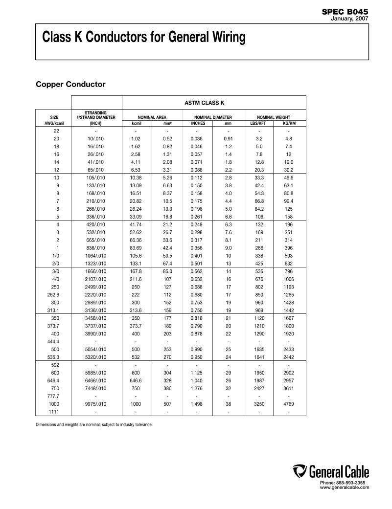
Phone: 888-593-3355www.generalcable.com
Class K Conductors for General Wiring
Copper Conductor
Dimensions and weights are nominal; subject to industry tolerance.
SPEC B045January, 2007
STRANDING SIZE #/STRAND DIAMETER NOMINAL AREA NOMINAL DIAMETER NOMINAL WEIGHT AWG/kcmil (INCH) kcmil mm2 INCHES mm LBS/KFT KG/KM
22 - - - - - - -
20 10/.010 1.02 0.52 0.036 0.91 3.2 4.8
18 16/.010 1.62 0.82 0.046 1.2 5.0 7.4
16 26/.010 2.58 1.31 0.057 1.4 7.8 12
14 41/.010 4.11 2.08 0.071 1.8 12.8 19.0
12 65/.010 6.53 3.31 0.088 2.2 20.3 30.2
10 105/.010 10.38 5.26 0.112 2.8 33.3 49.6
9 133/.010 13.09 6.63 0.150 3.8 42.4 63.1
8 168/.010 16.51 8.37 0.158 4.0 54.3 80.8
7 210/.010 20.82 10.5 0.175 4.4 66.8 99.4
6 266/.010 26.24 13.3 0.198 5.0 84.2 125
5 336/.010 33.09 16.8 0.261 6.6 106 158
4 420/.010 41.74 21.2 0.249 6.3 132 196
3 532/.010 52.62 26.7 0.298 7.6 169 251
2 665/.010 66.36 33.6 0.317 8.1 211 314
1 836/.010 83.69 42.4 0.356 9.0 266 396
1/0 1064/.010 105.6 53.5 0.401 10 338 503
2/0 1323/.010 133.1 67.4 0.501 13 425 632
3/0 1666/.010 167.8 85.0 0.562 14 535 796
4/0 2107/.010 211.6 107 0.632 16 676 1006
250 2499/.010 250 127 0.688 17 802 1193
262.6 2220/.010 222 112 0.680 17 850 1265
300 2989/.010 300 152 0.753 19 960 1428
313.1 3136/.010 313.6 159 0.750 19 969 1442
350 3458/.010 350 177 0.818 21 1120 1667
373.7 3737/.010 373.7 189 0.790 20 1210 1800
400 3990/.010 400 203 0.878 22 1290 1920
444.4 - - - - - - -
500 5054/.010 500 253 0.990 25 1635 2433
535.3 5320/.010 532 270 0.950 24 1641 2442
592 - - - - - - -
600 5985/.010 600 304 1.125 29 1950 2902
646.4 6466/.010 646.6 328 1.040 26 1987 2957
750 7448/.010 750 380 1.276 32 2427 3611
777.7 - - - - - - -
1000 9975/.010 1000 507 1.498 38 3250 4769
1111 - - - - - - -
ASTM CLASS K
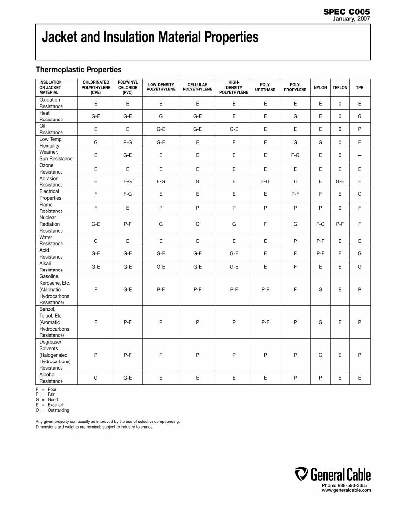
Phone: 888-593-3355www.generalcable.com
Jacket and Insulation Material Properties
Thermoplastic Properties INSULATION CHLORINATED POLYVINYL HIGH- OR JACKET POLYETHYLENE CHLORIDE
LOW-DENSITY CELLULAR DENSITY
POLY- POLY- NYLON TEFLON TPE
MATERIAL (CPE) (PVC) POLYETHYLENE POLYETHYLENE
POLYETHYLENE URETHANE PROPYLENE
Oxidation Resistance E E E E E E E E 0 E Heat Resistance
G-E G-E G G-E E E G E 0 G
Oil Resistance
E E G-E G-E G-E E E E 0 P
Low Temp. Flexibility
G P-G G-E E E E G G 0 E
Weather, Sun Resistance
E G-E E E E E F-G E 0
—
Ozone Resistance E E E E E E E E E E
Abrasion Resistance
E F-G F-G G E F-G 0 E G-E F
Electrical Properties
F F-G E E E E P-F F E G
Flame Resistance
F E P P P P P P 0 F
Nuclear Radiation G-E P-F G G G F G F-G P-F F Resistance Water Resistance G E E E E E P P-F E E
Acid Resistance
G-E G-E G-E G-E G-E E F P-F E G
Alkali Resistance
G-E G-E G-E G-E G-E E F E E G
Gasoline, Kerosene, Etc. (Alaphatic F G-E P-F P-F P-F P-F F G E P Hydrocarbons Resistance) Benzol, Toluol, Etc. (Aromatic F P-F P P P P-F P G E P Hydrocarbons Resistance) Degreaser Solvents (Halogenated P P-F P P P P P G E P Hydrocarbons) Resistance Alcohol Resistance
G G-E E E E E P P E E
P = Poor F = Fair G = Good E = Excellent O = Outstanding
Any given property can usually be improved by the use of selective compounding. Dimensions and weights are nominal; subject to industry tolerance.
SPEC C005January, 2007

Phone: 888-593-3355www.generalcable.com
Jacket and Insulation Material Properties
Thermoset Properties HYPALON® NITRILE INSULATION STYRENE NATURAL SYNTHETIC POLY- NEOPRENE CHLORO- OR RUBBER NITRILE/ ETHYLENE CROSS-LINKED CHLORINATED SILICONE OR JACKET BUTADIENE RUBBER RUBBER BUTADIENE SULFONATED BUTADINE POLY- PROPYLENE POLYETHYLENE POLYETHYLENE RUBBER MATERIAL RUBBER POLYETHYLENE NITRILE CHLORIDE RUBBER (XLPE) (CPE) (SBR) (CSPE) (NBR) (NBR/PVC) (EPR) F F G G G E F E G E E E F-G F F F G E G G E G E G P P P P G G G-E G F G G-E F-G F-G G E E F-G F F F G-E 0 F 0 F F F F G E F-G G E G E 0 P P P P G E P G E E G-E 0 G-E E E E G-E G G-E E G F-G G-E F E E E E F G P F E E F-G 0 P P P P G G P G P F-G G F-G
F-G F-G F-G P F-G G F-G P G E G E G-E G-E E E G G-E G-E E G-E G-E G-E G-E F-G F-G F-G F-G G E G G G-E G-E E F-G F-G F-G F-G F-G G E F-G G G-E G-E E F-G
P P P P G F E G-E P F F P-F P P P P P-F F G G F F F P P P P P P P-F P G P F P P-G F G G F-G F G E G P E G-E G
P = Poor F = Fair G = Good E = Excellent O = Outstanding
Any given property can usually be improved by the use of selective compounding. Dimensions and weights are nominal; subject to industry tolerance.
OxidationResistance Heat Resistance Oil Resistance Low Temp. Flexibility Weather, Sun Resistance Ozone Resistance Abrasion Resistance Electrical Properties Flame Resistance Nuclear Radiation Resistance Water Resistance Acid Resistance Alkali Resistance Gasoline, Kerosene, Etc. (Alaphatic Hydrocarbons Resistance) Benzol, Toluol, Etc. (Aromatic Hydrocarbons Resistance) Degreaser Solvents (Halogenated Hydrocarbons) Resistance Alcohol Resistance
SPEC C010January, 2007

Phone: 888-593-3355www.generalcable.com
Recommended Reel Handling Practices
How to Handle Cable Reels
YES NO
Cradle both reel flanges between forks. Upended heavy reels will often arrive damaged. Refuse or receive subject to inspection for hidden damage.
Reels can be hoisted with a shaft extending through both flanges.
Do not lift by top flange. Cable or reel will be damaged.
Lower reels from truck using hydraulic gate, hoist or fork lift. LOWER CAREFULLY.
Never allow forks to touch cable surface or reel wrap.
Always load with flanges on edge and chock and block securely.
Never drop reels.
SPEC D005January, 2007
Phone: 888-593-3355www.generalcable.com
Recommended Cable Handling Practices
Unloading and Moving of Reels:Cable reels are never shipped upended (flat side down). Cable reels that arrive in this manner should be rejected or received only after a thorough inspection for damage.
See “Recommended Reel Handling Practices” on the following pages.
Upon receipt, a cable’s protective covering and/or lagging should be inspected for evidence of damage during shipment. If evidence of damage is found, a report should immediately be made to the carrier.
Under no circumstances should reels be dropped from the delivering vehicle to the ground.
Unloading and reel handling should be accomplished so that the equipment used does not contact the cable surface, and in the case of protective wrap, that the equipment does not contact the protective wrap.
If unloading and reel handling is accomplished by crane, either a cradle supporting the reel flanges or a shaft through the arbor hole should be used. If a fork lift is utilized, the forks must lift the reel at 90˚ to the flanges and the forks must be long enough to make complete lifting contact with both flanges. Under no circumstances should the forks come into contact with the cable surface or the protective wraps.
When a reel of cable is rolled from one point to another, care must be taken to see that there are no objects on the surface area which could contact or damage the cable surface or protective wrap.
If an inclined ramp is used for unloading, the ramp must be wide enough to contact both flanges completely. The stopping of the reels at the bottom shall be accomplished by using the reel flanges and not the surface of the cable.
SPEC D025January, 2007
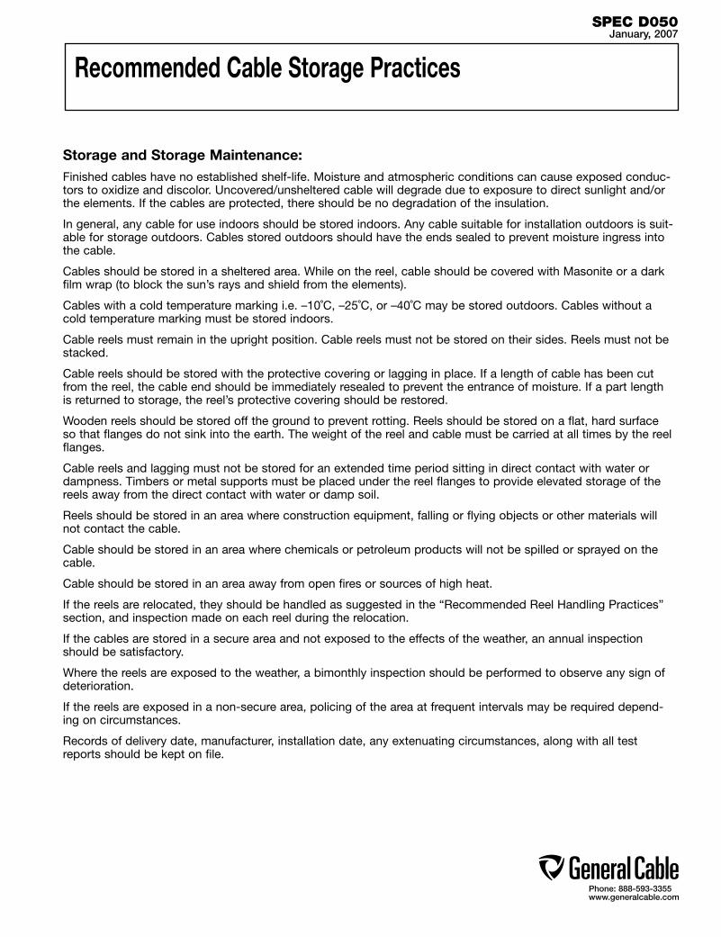
Phone: 888-593-3355www.generalcable.com
Recommended Cable Storage Practices
Storage and Storage Maintenance:Finished cables have no established shelf-life. Moisture and atmospheric conditions can cause exposed conduc-tors to oxidize and discolor. Uncovered/unsheltered cable will degrade due to exposure to direct sunlight and/or the elements. If the cables are protected, there should be no degradation of the insulation.
In general, any cable for use indoors should be stored indoors. Any cable suitable for installation outdoors is suit-able for storage outdoors. Cables stored outdoors should have the ends sealed to prevent moisture ingress into the cable.
Cables should be stored in a sheltered area. While on the reel, cable should be covered with Masonite or a dark film wrap (to block the sun’s rays and shield from the elements).
Cables with a cold temperature marking i.e. –10˚C, –25˚C, or –40˚C may be stored outdoors. Cables without a cold temperature marking must be stored indoors.
Cable reels must remain in the upright position. Cable reels must not be stored on their sides. Reels must not be stacked.
Cable reels should be stored with the protective covering or lagging in place. If a length of cable has been cut from the reel, the cable end should be immediately resealed to prevent the entrance of moisture. If a part length is returned to storage, the reel’s protective covering should be restored.
Wooden reels should be stored off the ground to prevent rotting. Reels should be stored on a flat, hard surface so that flanges do not sink into the earth. The weight of the reel and cable must be carried at all times by the reel flanges.
Cable reels and lagging must not be stored for an extended time period sitting in direct contact with water or dampness. Timbers or metal supports must be placed under the reel flanges to provide elevated storage of the reels away from the direct contact with water or damp soil.
Reels should be stored in an area where construction equipment, falling or flying objects or other materials will not contact the cable.
Cable should be stored in an area where chemicals or petroleum products will not be spilled or sprayed on the cable.
Cable should be stored in an area away from open fires or sources of high heat.
If the reels are relocated, they should be handled as suggested in the “Recommended Reel Handling Practices” section, and inspection made on each reel during the relocation.
If the cables are stored in a secure area and not exposed to the effects of the weather, an annual inspection should be satisfactory.
Where the reels are exposed to the weather, a bimonthly inspection should be performed to observe any sign of deterioration.
If the reels are exposed in a non-secure area, policing of the area at frequent intervals may be required depend-ing on circumstances.
Records of delivery date, manufacturer, installation date, any extenuating circumstances, along with all test reports should be kept on file.
SPEC D050January, 2007
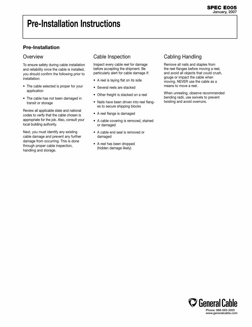
Phone: 888-593-3355www.generalcable.com
Pre-Installation Instructions
OverviewTo ensure safety during cable installation and reliability once the cable is installed, you should confirm the following prior to installation:
• The cable selected is proper for your application
• The cable has not been damaged in transit or storage
Review all applicable state and national codes to verify that the cable chosen is appropriate for the job. Also, consult your local building authority.
Next, you must identify any existing cable damage and prevent any further damage from occurring. This is done through proper cable inspection, handling and storage.
Cable InspectionInspect every cable reel for damage before accepting the shipment. Be particularly alert for cable damage if:
• A reel is laying flat on its side
• Several reels are stacked
• Other freight is stacked on a reel
• Nails have been driven into reel flang-es to secure shipping blocks
• A reel flange is damaged
• A cable covering is removed, stained or damaged
• A cable end seal is removed or damaged
• A reel has been dropped (hidden damage likely)
Cabling HandlingRemove all nails and staples from the reel flanges before moving a reel, and avoid all objects that could crush, gouge or impact the cable when moving. NEVER use the cable as a means to move a reel.
When unreeling, observe recommended bending radii, use swivels to prevent twisting and avoid overruns.
Pre-Installation
SPEC E005January, 2007
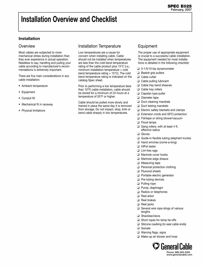
Phone: 888-593-3355www.generalcable.com
OverviewMost cables are subjected to more mechanical stress during installation than they ever experience in actual operation. Needless to say, handling and pulling your cable according to manufacturer’s recom-mendations is extremely important.
There are five main considerations in any cable installation:
• Ambient temperature
• Equipment
• Conduit fill
• Mechanical fit in raceway
• Physical limitations
Installation TemperatureLow temperatures are a cause for concern when installing cable. Cable should not be installed when temperatures are less than the cold bend temperature rating of the cable product plus 15°C (i.e., minimum installation temperature = cold bend temperature rating + 15°C). The cold bend temperature rating is indicated on the catalog Spec sheet.
Prior to performing a low temperature (less than 10°F) cable installation, cable should be stored for a minimum of 24 hours at a temperature of 55°F or higher.
Cable should be pulled more slowly and trained in place the same day it is removed from storage. Do not impact, drop, kink or bend cable sharply in low temperatures.
EquipmentThe proper use of appropriate equipment is crucial to a successful cable installation. The equipment needed for most installa-tions is detailed in the following checklist:
0-1/5/10 kip dynamometer Basket grip pullers Cable cutter Cable pulling lubricant Cable tray bend sheaves Cable tray rollers Capstan type puller Diameter tape Duct cleaning mandrels Duct testing mandrels Electric safety blankets and clamps Extension cords and GFCI protection Fishtape or string blower/vacuum Flood lamps Gang rollers; with at least 4 ft.
effective radius Gloves Guide-in flexible tubing (elephant trunks) Hand winches (come-a-long) HiPot tester Lint-free rags Manhole cover hooks Manhole edge sheave Measuring tape Personal protection clothing Plywood sheets Portable electric generator Pre-lubing devices Pulling rope Pump, diaphragm Radios or telephones Reel arbor Reel brakes Reel jacks Several wire rope slings of various
lengths Shackles/clevis Short ropes for temp tie-offs Silicone caulking (to seal cable ends) Swivels Warning flags, signs Make-up air blower and hose
Installation
Installation Overview and Checklist
SPEC E025February, 2007
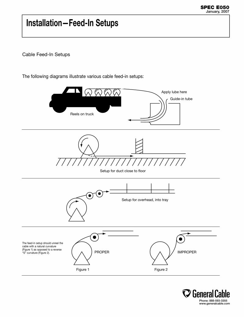
Phone: 888-593-3355www.generalcable.com
Installation—Feed-In Setups
The following diagrams illustrate various cable feed-in setups:
Cable Feed-In Setups
Reels on truck
Apply lube here
Guide-in tube
Setup for duct close to floor
Setup for overhead, into tray
Figure 1 Figure 2
IMPROPERPROPER
The feed-in setup should unreel the cable with a natural curvature (Figure 1) as opposed to a reverse “S” curvature (Figure 2).
SPEC E050January, 2007
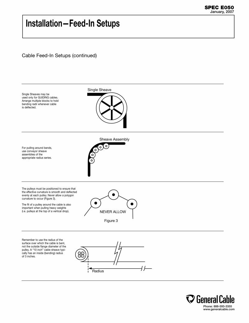
Phone: 888-593-3355www.generalcable.com
Installation—Feed-In Setups
Single Sheave
Sheave Assembly
Figure 3
NEVER ALLOW
Radius
Remember to use the radius of the surface over which the cable is bent, not the outside flange diameter of the pulley. A “10 inch” cable sheave typi-cally has an inside (bending) radius of 3 inches.
Single Sheaves may be used only for GUIDING cables. Arrange multiple blocks to hold bending radii whenever cable is deflected.
For pulling around bends, use conveyor sheave assemblies of the appropriate radius series.
The pulleys must be positioned to ensure that the effective curvature is smooth and deflected evenly at each pulley. Never allow a polygon curvature to occur (Figure 3).
The fit of a pulley around the cable is also important when pulling heavy weights (i.e. pulleys at the top of a vertical drop).
Cable Feed-In Setups (continued)
SPEC E050January, 2007
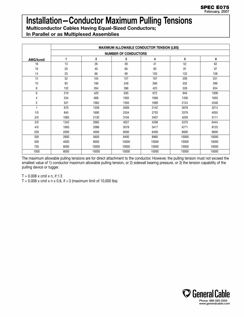
Phone: 888-593-3355www.generalcable.com
Installation—Conductor Maximum Pulling TensionsMulticonductor Cables Having Equal-Sized Conductors; In Parallel or as Multiplexed Assemblies
SPEC E075February, 2007
MAXIMUM ALLOWABLE CONDUCTOR TENSION (LBS)
NUMBER OF CONDUCTORS
AWG/kcmil 1 2 3 4 5 6
18 13 26 39 41 52 62
16 20 40 60 65 81 97
14 33 66 99 105 132 158
12 52 104 157 167 209 251
10 83 166 249 266 332 399
8 132 264 396 423 528 634
6 210 420 630 672 840 1008
4 334 668 1002 1069 1336 1603
2 531 1062 1593 1699 2124 2548
1 670 1339 2009 2142 2678 3214
1/0 845 1690 2534 2703 3379 4055
2/0 1065 2130 3194 3407 4259 5111
3/0 1342 2685 4027 4296 5370 6444
4/0 1693 3386 5078 5417 6771 8125
250 2000 4000 6000 6400 8000 9600
350 2800 5600 8400 8960 10000 10000
500 4000 8000 10000 10000 10000 10000
750 6000 10000 10000 10000 10000 10000
1000 8000 10000 10000 10000 10000 10000
The maximum allowable pulling tensions are for direct attachment to the conductor. However, the pulling tension must not exceed the smallest value of 1) conductor maximum allowable pulling tension, or 2) sidewall bearing pressure, or 3) the tension capability of the pulling device or tugger. T = 0.008 x cmil x n, if < 3 T = 0.008 x cmil x n x 0.8, if > 3 (maximum limit of 10,000 lbs)
—
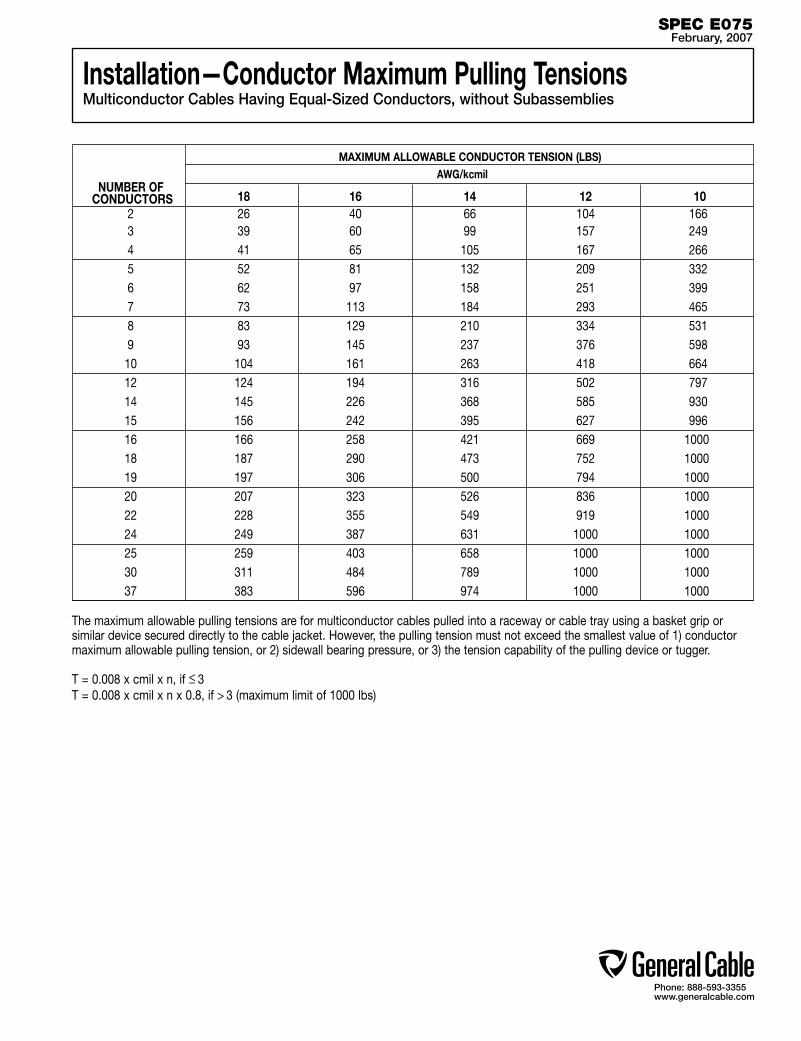
Phone: 888-593-3355www.generalcable.com
Installation—Conductor Maximum Pulling TensionsMulticonductor Cables Having Equal-Sized Conductors, without Subassemblies
SPEC E075February, 2007
MAXIMUM ALLOWABLE CONDUCTOR TENSION (LBS)
NUMBER OF AWG/kcmil
CONDUCTORS 18 16 14 12 10 2 26 40 66 104 166 3 39 60 99 157 249 4 41 65 105 167 266 5 52 81 132 209 332 6 62 97 158 251 399 7 73 113 184 293 465 8 83 129 210 334 531 9 93 145 237 376 598 10 104 161 263 418 664 12 124 194 316 502 797 14 145 226 368 585 930 15 156 242 395 627 996 16 166 258 421 669 1000 18 187 290 473 752 1000 19 197 306 500 794 1000 20 207 323 526 836 1000 22 228 355 549 919 1000 24 249 387 631 1000 1000 25 259 403 658 1000 1000 30 311 484 789 1000 1000 37 383 596 974 1000 1000
The maximum allowable pulling tensions are for multiconductor cables pulled into a raceway or cable tray using a basket grip or similar device secured directly to the cable jacket. However, the pulling tension must not exceed the smallest value of 1) conductor maximum allowable pulling tension, or 2) sidewall bearing pressure, or 3) the tension capability of the pulling device or tugger. T = 0.008 x cmil x n, if < 3 T = 0.008 x cmil x n x 0.8, if > 3 (maximum limit of 1000 lbs)
—
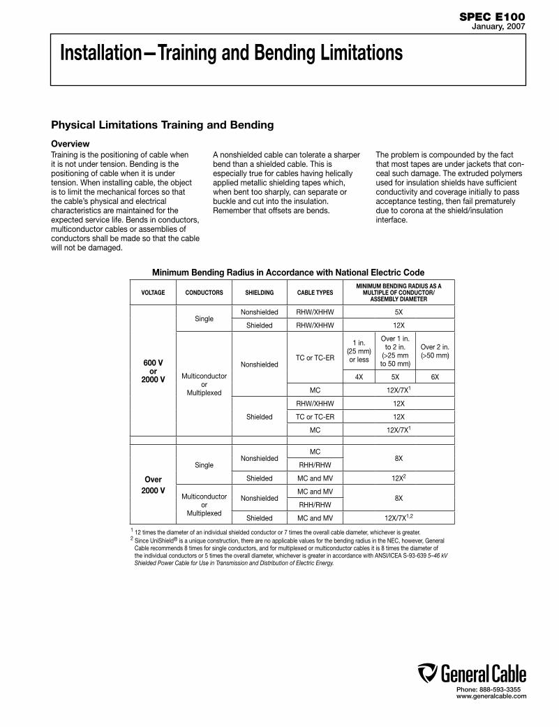
Phone: 888-593-3355www.generalcable.com
Installation—Training and Bending Limitations
OverviewTraining is the positioning of cable when it is not under tension. Bending is the positioning of cable when it is under tension. When installing cable, the object is to limit the mechanical forces so that the cable’s physical and electrical characteristics are maintained for the expected service life. Bends in conductors, multiconductor cables or assemblies of conductors shall be made so that the cable will not be damaged.
Physical Limitations Training and Bending
1 12 times the diameter of an individual shielded conductor or 7 times the overall cable diameter, whichever is greater.2 Since UniShield® is a unique construction, there are no applicable values for the bending radius in the NEC, however, General Cable recommends 8 times for single conductors, and for multiplexed or multiconductor cables it is 8 times the diameter of the individual conductors or 5 times the overall diameter, whichever is greater in accordance with ANSI/ICEA S-93-639 5–46 kV Shielded Power Cable for Use in Transmission and Distribution of Electric Energy.
SPEC E100January, 2007
Minimum Bending Radius in Accordance with National Electric Code
VOLTAGE CONDUCTORS SHIELDING CABLE TYPESMINIMUM BENDING RADIUS AS A
MULTIPLE OF CONDUCTOR/ ASSEMBLY DIAMETER
600 V or
2000 V
SingleNonshielded RHW/XHHW 5X
Shielded RHW/XHHW 12X
Multiconductor or
Multiplexed
NonshieldedTC or TC-ER
1 in. (25 mm) or less
Over 1 in. to 2 in.
(>25 mm to 50 mm)
Over 2 in. (>50 mm)
4X 5X 6X
MC 12X/7X1
Shielded
RHW/XHHW 12X
TC or TC-ER 12X
MC 12X/7X1
Over 2000 V
SingleNonshielded
MC8X
RHH/RHW
Shielded MC and MV 12X2
Multiconductor or
Multiplexed
NonshieldedMC and MV
8XRHH/RHW
Shielded MC and MV 12X/7X1,2
A nonshielded cable can tolerate a sharper bend than a shielded cable. This is especially true for cables having helically applied metallic shielding tapes which, when bent too sharply, can separate or buckle and cut into the insulation. Remember that offsets are bends.
The problem is compounded by the fact that most tapes are under jackets that con-ceal such damage. The extruded polymers used for insulation shields have sufficient conductivity and coverage initially to pass acceptance testing, then fail prematurely due to corona at the shield/insulation interface.

Phone: 888-593-3355www.generalcable.com
Installation—Maximum Sidewall Pressure
Overview Sidewall bearing pressure (SWBP), or sidewall
loading, is the radial force exerted on a cable being pulled around a conduit bend or sheave. Excessive SWBP can crush a cable and is, therefore, one of the most restrictive factors in installations having bends and requiring high pulling tensions.
SWBP is reduced by increasing the radius of bends. To illustrate, a 15kV 350 kcmil cable installation dropping six feet vertically under-ground, traveling horizontally, and then rising to a motor should have bends of at least six feet in radius to maximize the horizontal distance and still be within the SWBP of 500 lbs/ft.
The maximum tension that can safely be applied to the cable during installation can be calculated using the maximum SWBP for the cable and the radius of the bend it is traversing.
For example, a cable having a maximum SWBP of 300 lb/ft that is being pulled around a bend having a radius of 2 feet should have no more than 300 lbs/ft x 2 ft or 600 lbs tension applied to it as the cable exits the bend.
Cable type SWBP (lbs/ft)
300V Nonshielded, 300V and 600V Shielded Control & Instrumentation 500
600V Nonshielded Control & Instrumentation 500
600V and 2400V Nonshielded Power 1000
5kV and 35kV Power 1000
Interlocked Armor Cable (all voltages) 500
Sidewall Load
Tension
*Yellow 77 not recommended for use with UniShield® cables.
For LSZH jacketed cable, consult with pulling compound manufacturers.Other wire pulling compounds may be suitable for use with General Cable constructions. Contact the wire pulling compound manufacturer regarding the suitability of their products with specific General Cable products.
General Cable’s Approval List of Cable Pulling LubricantsThe following manufacturers, who are listed in the 2006 UL Electrical Construction Equipment Directory, provide wire pulling compounds intended for use as lubricants in installing electrical conductors in raceways. These manufacturers have had some of their products investigated by Underwriters Laboratories (UL) to determine their compatibility with conductor insulation and coverings.
Since it is not feasible to test every possible combination of cable material with every wire pulling compound, the installer should check with the pulling compound manufacturer or the cable manufacturer to determine compatibility between specific cable materials and the pulling compound.
The Listing Mark for these products includes the UL symbol, together with the word “LISTED,” a control number and the product name “Wire Pulling Compound.” Refer to the latest edition of the UL Electrical Construction Equipment Directory for the current listing of manufacturers of wire pulling compounds and their control numbers.
SPEC E125February, 2007
J. C. Whitlam Mfg. Co.
Klein Tools Inc.
Madison Electric Products Inc.
Rainbow Technology Corp.
Rectorseal
Robinette Inc., DBA Electro Compounds Co.
Thomas & Betts Corp.
3 M Company
American Bentonite International Inc.
American Polywater Corp.
Arnco Corp.
Dura-Line Corp.
Formulated Solutions LLC
Compound Co.
Greenlee Textron
Ideal Industries Inc.*

Phone: 888-593-3355www.generalcable.com
DC “Hi-Pot” Pre-Test Guidelines for MV Cable
SPEC F005January, 2007
The test voltage should be increased in steps of 10kV, or minimum of 5 steps. The duration at each step should be long enough for the current to reach a steady value (1 minute suggested). The test current will momentarily increase for each voltage increment due to charging of the capacitance and the dielectric absorption characteris-tics of the insulation. Stabilized current should be recorded at each step.
The maximum test voltage should be maintained for 15 minutes (new cable, shielded) / 5 minutes (non-shielded). Leakage current should be recorded each minute after the maximum test voltage has been reached.
Increase of leakage current at any step point may be an indication of a cable insulation problem. Failure of the cable or cable accessories may result unless the voltage is rapidly reduced.
Otherwise, the leakage current should stabilize after about 5 minutes. Leakage current is essentially a function of the construction and length of cable but it can be influenced by the test conditions (wind and humidity) as well as the test apparatus (leads).
Typical leakage currents in the order of 100 – 150 microamperes or higher are not unusual. A defective installation is identified by increasing leakage current with time, at a fixed dc voltage.
All testing should be performed by qualified personnel taking all appropriate safety precautions
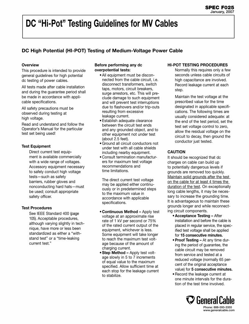
Phone: 888-593-3355www.generalcable.com
DC “Hi-Pot” Testing Guidelines for MV Cables
DC High Potential (HI-POT) Testing of Medium-Voltage Power Cable
OverviewThis procedure is intended to provide general guidelines for high potential dc testing of power cables.
All tests made after cable installation and during the guarantee period shall be made in accordance with appli-cable specifications.
All safety precautions must be observed during testing at high voltage.
Read and understand and follow the Operator’s Manual for the particular test set being used!
Test Equipment Direct current test equip-
ment is available commercially with a wide range of voltages. Accessory equipment necessary to safely conduct high voltage tests—such as safety barriers, rubber gloves and nonconducting hard hats—must be used; consult appropriate safety officer.
Test Procedures See IEEE Standard 400 (page
105). Acceptable procedures, although varying slightly in tech-nique, have more or less been standardized as either a “with-stand test” or a “time-leaking current test.”
Before performing any dc overpotential tests:
• All equipment must be discon-nected from the cable circuit, i.e. disconnect transformers, switch taps, motors, circuit breakers, surge arrestors, etc. This will pre-clude damage to such equipment and will prevent test interruptions due to flashovers and/or trip-outs resulting from excessive leakage current.
• Establish adequate clearance between the circuit test ends and any grounded object, and to other equipment not under test (about 2.5 feet).
• Ground all circuit conductors not under test with all cable shields including nearby equipment.
• Consult termination manufactur-ers for maximum test voltage recommendations and time limitations.
The direct current test voltage may be applied either continu-ously or in predetermined steps to the maximum value in accordance with applicable specifications.
• Continuous Method – Apply test voltage at an approximate rise rate of 1 kV per second or 75% of the rated current output of the equipment, whichever is less. Some equipment will take longer to reach the maximum test volt-age because of the amount of charging current.
• Step Method – Apply test volt-age slowly in 5 to 7 increments of equal value to the maximum specified. Allow sufficient time at each stop for the leakage current to stabilize.
HI-POT TESTING PROCEDURES Normally this requires only a few
seconds unless cable circuits of high capacitance are involved.
Record leakage current at each step.
Maintain the test voltage at the prescribed value for the time designated in applicable specifi-cations. The following times are usually considered adequate: at the end of the test period, set the test set voltage control to zero, allow the residual voltage on the circuit to decay, then ground the conductor just tested.
CAUTIONIt should be recognized that dc charges on cable can build up to potentially dangerous levels if grounds are removed too quickly. Maintain solid grounds after the test on the cable for at least 4 times the duration of the test. On exceptionally long cable lengths, it may be neces-sary to increase the grounding time. It is advantageous to maintain these grounds longer and while reconnect-ing circuit components.
• Acceptance Testing – After installation and before the cable is placed in regular service, the spec-ified test voltage shall be applied for 15 consecutive minutes.
• Proof Testing – At any time dur-ing the period of guarantee, the cable circuit may be removed from service and tested at a reduced voltage (normally 65 per-cent of the original acceptance value) for 5 consecutive minutes.
• Record the leakage current at one minute intervals for the dura-tion of the test time involved.
SPEC F025January, 2007
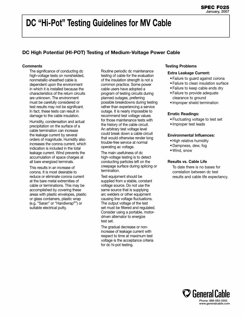
Phone: 888-593-3355www.generalcable.com
DC “Hi-Pot” Testing Guidelines for MV Cable
DC High Potential (HI-POT) Testing of Medium-Voltage Power Cable
SPEC F025January, 2007
Comments The significance of conducting dc
high-voltage tests on nonshielded, nonmetallic-sheathed cable is dependent upon the environment in which it is installed because the characteristics of the return circuits are unknown. The environment must be carefully considered or test results may not be significant. In fact, these tests can result in damage to the cable insulation.
Humidity, condensation and actual precipitation on the surface of a cable termination can increase the leakage current by several orders of magnitude. Humidity also increases the corona current, which indication is included in the total leakage current. Wind prevents the accumulation of space charges at all bare energized terminals.
This results in an increase of corona. It is most desirable to reduce or eliminate corona current at the bare metal extremities of cable or terminations. This may be accomplished by covering these areas with plastic envelopes, plastic or glass containers, plastic wrap (e.g. “Saran” or “Handiwrap®”) or suitable electrical putty.
Routine periodic dc maintenance testing of cable for the evaluation of the insulation strength is not a common practice. Some power cable users have adopted a program of testing circuits during planned outages, preferring possible breakdowns during testing rather than experiencing a service outage. It is nearly impossible to recommend test voltage values for those maintenance tests with the history of the cable circuit. An arbitrary test voltage level could break down a cable circuit that would otherwise render long trouble-free service at normal operating ac voltage.
The main usefulness of dc high-voltage testing is to detect conducting particles left on the creepage surface during splicing or termination.
Test equipment should be supplied from a stable, constant voltage source. Do not use the same source that is supplying arc welders or other equipment causing line voltage fluctuations. The output voltage of the test set must be filtered and regulated. Consider using a portable, motor-driven alternator to energize test set.
The gradual decrease or non-increase of leakage current with respect to time at maximum test voltage is the acceptance criteria for dc hi-pot testing.
Testing Problems
Extra Leakage Current:• Failure to guard against corona• Failure to clean insulation surface• Failure to keep cable ends dry• Failure to provide adequate
clearance to ground• Improper shield termination
Erratic Readings:• Fluctuating voltage to test set• Improper test leads
Environmental Influences:• High relative humidity• Dampness, dew, fog• Wind, snow
Results vs. Cable Life To date there is no bases for
correlation between dc test results and cable life expectancy.
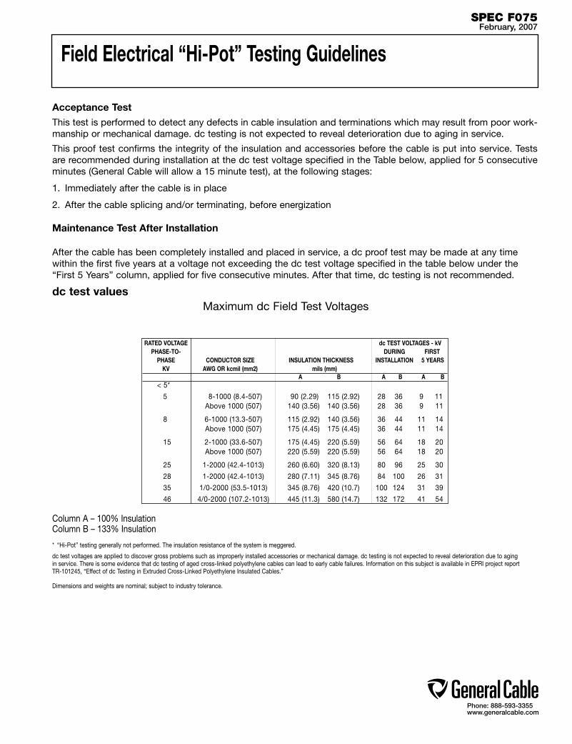
Phone: 888-593-3355www.generalcable.com
Field Electrical “Hi-Pot” Testing Guidelines
Acceptance TestThis test is performed to detect any defects in cable insulation and terminations which may result from poor work-manship or mechanical damage. dc testing is not expected to reveal deterioration due to aging in service.
This proof test confirms the integrity of the insulation and accessories before the cable is put into service. Tests are recommended during installation at the dc test voltage specified in the Table below, applied for 5 consecutive minutes (General Cable will allow a 15 minute test), at the following stages:
1. Immediately after the cable is in place
2. After the cable splicing and/or terminating, before energization
Maintenance Test After Installation
After the cable has been completely installed and placed in service, a dc proof test may be made at any time within the first five years at a voltage not exceeding the dc test voltage specified in the table below under the “First 5 Years” column, applied for five consecutive minutes. After that time, dc testing is not recommended.
dc test values Maximum dc Field Test Voltages
Column A – 100% InsulationColumn B – 133% Insulation
* “Hi-Pot” testing generally not performed. The insulation resistance of the system is meggered.
dc test voltages are applied to discover gross problems such as improperly installed accessories or mechanical damage. dc testing is not expected to reveal deterioration due to aging in service. There is some evidence that dc testing of aged cross-linked polyethylene cables can lead to early cable failures. Information on this subject is available in EPRI project report TR-101245, “Effect of dc Testing in Extruded Cross-Linked Polyethylene Insulated Cables.”
RATED VOLTAGE dc TEST VOLTAGES - kV PHASE-TO- DURING FIRST PHASE CONDUCTOR SIZE INSULATION THICKNESS INSTALLATION 5 YEARS KV AWG OR kcmil (mm2) mils (mm) A B A B A B < 5*
5 8-1000 (8.4-507) 90 (2.29) 115 (2.92) 28 36 9 11 Above 1000 (507) 140 (3.56) 140 (3.56) 28 36 9 11
8 6-1000 (13.3-507) 115 (2.92) 140 (3.56) 36 44 11 14 Above 1000 (507) 175 (4.45) 175 (4.45) 36 44 11 14
15 2-1000 (33.6-507) 175 (4.45) 220 (5.59) 56 64 18 20 Above 1000 (507) 220 (5.59) 220 (5.59) 56 64 18 20
25 1-2000 (42.4-1013) 260 (6.60) 320 (8.13) 80 96 25 30
28 1-2000 (42.4-1013) 280 (7.11) 345 (8.76) 84 100 26 31
35 1/0-2000 (53.5-1013) 345 (8.76) 420 (10.7) 100 124 31 39
46 4/0-2000 (107.2-1013) 445 (11.3) 580 (14.7) 132 172 41 54
Dimensions and weights are nominal; subject to industry tolerance.
SPEC F075February, 2007

Phone: 888-593-3355www.generalcable.com
Emergency Overload Current Guidelines
The increase or decrease of the load current is not associated with an instantaneous change of the cable tempera-ture. Hence, during emergency conditions, the cable may be overloaded for short periods of time at the maximum overload temperature of 130°C/140°C for cable rated at 90°C/105˚C continuous.
Operations at the emergency overload temperature shall not exceed 1500 cumulative hours during the lifetime of the cable. Lower temperature for emergency overload conditions may be required due to the type of material used in the cable splices and terminations or environmental conditions.
SPEC F100January, 2007
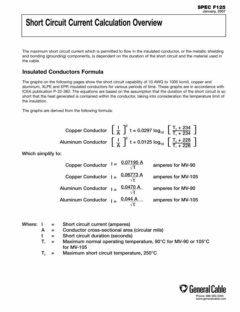
Phone: 888-593-3355www.generalcable.com
Copper Conductor t = 0.0297 log10
Aluminum Conductor t = 0.0125 log10
Which simplify to:
Copper Conductor amperes for MV-90
Copper Conductor amperes for MV-105
Aluminum Conductor amperes for MV-90
Aluminum Conductor amperes for MV-105
Short Circuit Current Calculation Overview
The maximum short circuit current which is permitted to flow in the insulated conductor, or the metallic shielding and bonding (grounding) components, is dependent on the duration of the short circuit and the material used in the cable.
Insulated Conductors Formula
The graphs on the following pages show the short circuit capability of 10 AWG to 1000 kcmil, copper and aluminum, XLPE and EPR insulated conductors for various periods of time. These graphs are in accordance with ICEA publication P-32-382. The equations are based on the assumption that the duration of the short circuit is so short that the heat generated is contained within the conductor, taking into consideration the temperature limit of the insulation.
The graphs are derived from the following formula:
Where: I = Short circuit current (amperes) A = Conductor cross-sectional area (circular mils) t = Short circuit duration (seconds) T1 = Maximum normal operating temperature, 90°C for MV-90 or 105°C for MV-105 T2 = Maximum short circuit temperature, 250°C
[ ]2I—A [ ]T2 + 234——————T1 + 234
[ ]T2 + 228——————T1 + 228
0.07195 AI = t
0.06773 AI = t 0.0470 A I = t
[ ]2I—A
SPEC F125January, 2007
0.044 A I = t

0.058 AI = ————— t
A=Shield area (circular mils*)t=Short circuit duration (seconds)I=Current (amperes)Temperature exclusion range of 100°C–200°C
1000000
100000
10000
1000
100
10 8 6 4 2 1 1/0 2/0 3/0 4/0 250 350 500 750 1000
1 Cycles16 Cycles
2 Cycles30 Cycles
4 Cycles60 Cycles
8 Cycles100 Cycles
Phone: 888-593-3355www.generalcable.com
Short Circuit CurrentsAllowable Short Circuit Currents For Thermoset Insulated Copper Conductors Rated For 90°C Maximum Continuous Operation
SPEC F125January, 2007
Sho
rt C
ircui
t C
urre
nt—
Am
per
es
Conductor Size (AWG/kcmil)
Reprinted with permission from ICEA P-32-382 Short Circuit characteristics of Insulated Conductors, Copyright 2006, Insulated Cable Engineers Association, Carrollton, GA 30112. This reprint is not the referenced subject, which is represented only by the standard in its entirety.
I = Short Circuit Current–AmperesA = Conductor Area–Circular Milst = Time of Short Circuit–SecondsT1 = Maximum Operating Temperature–90°CT2 = Maximum Short Circuit Temperature–250°C
Curves Based on the Formula
t = 0.0297 log10[ ]IA [ ]T2 + 234
T1 + 234
2
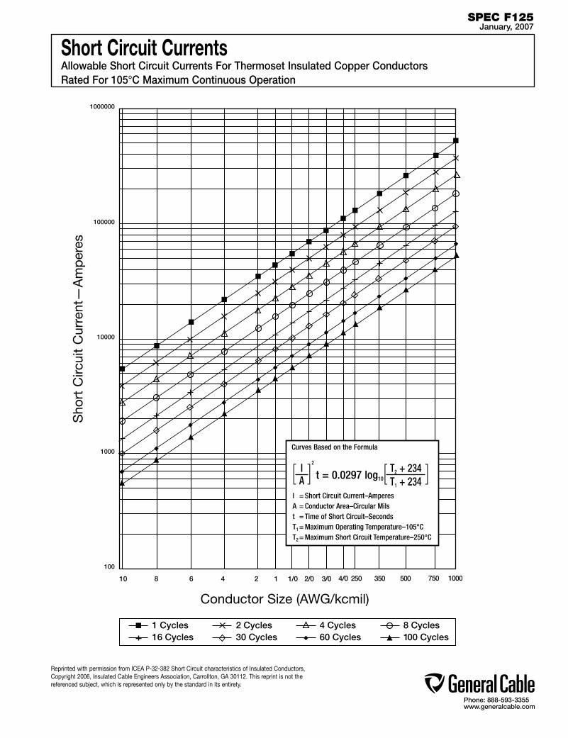
0.058 AI = ————— t
A=Shield area (circular mils*)t=Short circuit duration (seconds)I=Current (amperes)Temperature exclusion range of 100°C–200°C
1000000
100000
10000
1000
100
10 8 6 4 2 1 1/0 2/0 3/0 4/0 250 350 500 750 1000
1 Cycles16 Cycles
2 Cycles30 Cycles
4 Cycles60 Cycles
8 Cycles100 Cycles
Phone: 888-593-3355www.generalcable.com
Short Circuit CurrentsAllowable Short Circuit Currents For Thermoset Insulated Copper Conductors Rated For 105°C Maximum Continuous Operation
SPEC F125January, 2007
Sho
rt C
ircui
t C
urre
nt—
Am
per
es
Conductor Size (AWG/kcmil)
Reprinted with permission from ICEA P-32-382 Short Circuit characteristics of Insulated Conductors, Copyright 2006, Insulated Cable Engineers Association, Carrollton, GA 30112. This reprint is not the referenced subject, which is represented only by the standard in its entirety.
I = Short Circuit Current–AmperesA = Conductor Area–Circular Milst = Time of Short Circuit–SecondsT1 = Maximum Operating Temperature–105°CT2 = Maximum Short Circuit Temperature–250°C
Curves Based on the Formula
t = 0.0297 log10[ ]IA [ ]T2 + 234
T1 + 234
2

1000000
100000
10000
1000
100
10 8 6 4 2 1 1/0 2/0 3/0 4/0 250 350 500 750 1000
1 Cycles16 Cycles
2 Cycles30 Cycles
4 Cycles60 Cycles
8 Cycles100 Cycles
Phone: 888-593-3355www.generalcable.com
Short Circuit CurrentsAllowable Short Circuit Currents For Thermoset Insulated Aluminum Conductors Rated For 90°C Maximum Continuous Operation
SPEC F125January, 2007
Sho
rt C
ircui
t C
urre
nt—
Am
per
es
Conductor Size (AWG/kcmil)
Reprinted with permission from ICEA P-32-382 Short Circuit characteristics of Insulated Conductors, Copyright 2006, Insulated Cable Engineers Association, Carrollton, GA 30112. This reprint is not the referenced subject, which is represented only by the standard in its entirety.
I = Short Circuit Current–AmperesA = Conductor Area–Circular Milst = Time of Short Circuit–SecondsT1 = Maximum Operating Temperature–90°CT2 = Maximum Short Circuit Temperature–250°C
Curves Based on the Formula
t = 0.0125 log10[ ]IA [ ]T2 + 228
T1 + 228
2

1000000
100000
10000
1000
100
10 8 6 4 2 1 1/0 2/0 3/0 4/0 250 350 500 750 1000
1 Cycles16 Cycles
2 Cycles30 Cycles
4 Cycles60 Cycles
8 Cycles100 Cycles
Phone: 888-593-3355www.generalcable.com
Short Circuit CurrentsAllowable Short Circuit Currents For Thermoset Insulated Aluminum Conductors Rated For 105°C Maximum Continuous Operation
SPEC F125January, 2007
Sho
rt C
ircui
t C
urre
nt—
Am
per
es
Conductor Size (AWG/kcmil)
Reprinted with permission from ICEA P-32-382 Short Circuit characteristics of Insulated Conductors, Copyright 2006, Insulated Cable Engineers Association, Carrollton, GA 30112. This reprint is not the referenced subject, which is represented only by the standard in its entirety.
I = Short Circuit Current–AmperesA = Conductor Area–Circular Milst = Time of Short Circuit–SecondsT1 = Maximum Operating Temperature–105°CT2 = Maximum Short Circuit Temperature–250°C
Curves Based on the Formula
t = 0.0125 log10[ ]IA [ ]T2 + 228
T1 + 228
2
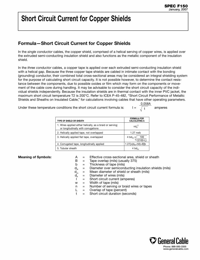
Phone: 888-593-3355www.generalcable.com
Meaning of Symbols: A = Effective cross-sectional area, shield or sheath B = Tape overlap (mils) (usually 375) b = Thickness of tape (mils) dis = Diameter over semiconducting insulation shields (mils) dm = Mean diameter of shield or sheath (mils) ds = Diameter of wires (mils) I = Short circuit current (amperes) w = Width of tape (mils) n = Number of serving or braid wires or tapes L = Overlap of tape (percent) t = Short circuit duration (seconds)
Formula—Short Circuit Current for Copper Shields
In the single conductor cables, the copper shield, comprised of a helical serving of copper wires, is applied over the extruded semi-conducting insulation shield and also functions as the metallic component of the insulation shield.
In the three conductor cables, a copper tape is applied over each extruded semi-conducting insulation shield with a helical gap. Because the three copper tape shields are cabled in intimate contact with the bonding (grounding) conductor, their combined total cross-sectional areas may be considered an integral shielding system for the purpose of calculating short circuit capacity. It is not possible however, to determine the contact resis-tance between the components, due to possible oxides or film which may form on the components or move-ment of the cable core during handling. It may be advisable to consider the short circuit capacity of the indi-vidual shields independently. Because the insulation shields are in thermal contact with the inner PVC jacket, the maximum short circuit temperature T2 is 200°C. Refer to ICEA P-45-482, “Short Circuit Performance of Metallic Shields and Sheaths on Insulated Cable,” for calculations involving cables that have other operating parameters.
Under these temperature conditions the short circuit current formula is: I = amperes0.058A _________
t
Short Circuit Current for Copper Shields
FORMULA FORTYPE OF SHIELD OR SHEATH CALCULATING A
1. Wires applied either helically, as a braid or serving; or longitudinally with corrugations
nds
2. Helically applied tape, not overlapped 1.27 nwb
3. Helically applied flat tape, overlapped 4 bdm x 100 2(100-L)4. Corrugated tape, longitudinally applied 1.27[π(dis+50)+B]b
5. Tubular sheath 4 bdm
SPEC F150January, 2007
2

1
.9
.8
.7
.6
.5
.4
.3
.2
.1
1009080
70
60
50
40
30
20
1098
7
6
5
4
3
2
10 20 30 40 50 60 70 80 90 100
200
300
400
500
600
700
800
900
1000
1 CYCLE = 0.01667 SECONDS
2 CYCLES = 0.0333 SECONDS
4 CYCLES = 0.0667 SECONDS
8 CYCLES = 0.1333 SECONDS
16 CYCLES = 0.2667 SECONDS
30 CYCLES = 0.5000 SECONDS
60 CYCLES = 1.0000 SECONDS
100 CYCLES = 1.6667 SECONDS
Circular Mils in kcmil
Sho
rt C
ircui
t C
urre
nt—
Kilo
Am
per
es
Phone: 888-593-3355www.generalcable.com
Formula—Short Circuit Currents for Copper Shields
Allowable Copper Shield Short Circuit Currents for 5–15 kV
SPEC F150January, 2007
0.058AI = _______ t
A=Shield area (circular mils)t=Short circuit duration (seconds)I=Current (amperes)Temperature excursion range of 100°C–200°C

1
.9
.8
.7
.6
.5
.4
.3
.2
.1
1009080
70
60
50
40
30
20
1098
7
6
5
4
3
2
10 20 30 40 50 60 70 80 90 100
200
300
400
500
600
700
800
900
1000
1 CYCLE = 0.0167 SECONDS
2 CYCLES = 0.0333 SECONDS
4 CYCLES = 0.0667 SECONDS
8 CYCLES = 0.1333 SECONDS
16 CYCLES = 0.2667 SECONDS
30 CYCLES = 0.5000 SECONDS
60 CYCLES = 1.0000 SECONDS
100 CYCLES = 1.6667 SECONDS
Circular Mils in kcmil
Sho
rt C
ircui
t C
urre
nt—
Kilo
Am
per
es
Phone: 888-593-3355www.generalcable.com
Formula—Short Circuit Currents for Copper Shields
Allowable Copper Shield Short Circuit Currents for 25–46 kV
SPEC F150January, 2007
Circular Mils in kcmil
0.060AI = _______ tA= Shield area (circular mils)t= Short circuit duration (seconds)I= Current (amperes)Temperature excursion 95°C–200°C
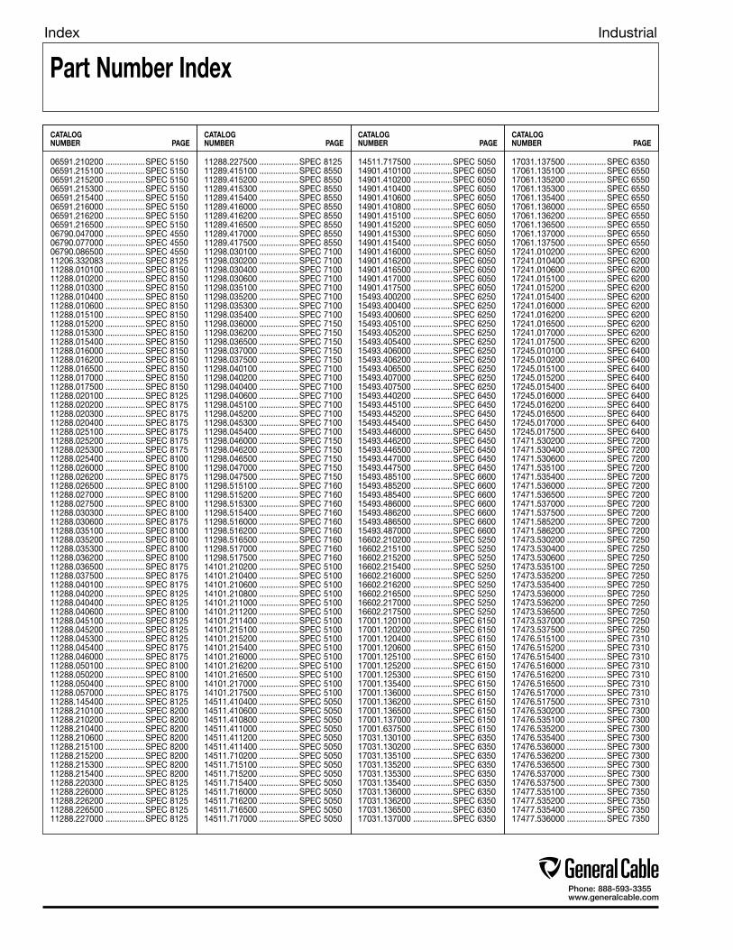
Index Industrial
Part Number Index
CATALOGNUMBER PAGE
CATALOGNUMBER PAGE
CATALOGNUMBER PAGE
CATALOGNUMBER PAGE
06591.210200 .................SPEC 515006591.215100 .................SPEC 515006591.215200 .................SPEC 515006591.215300 .................SPEC 515006591.215400 .................SPEC 515006591.216000 .................SPEC 515006591.216200 .................SPEC 515006591.216500 .................SPEC 515006790.047000 .................SPEC 455006790.077000 .................SPEC 455006790.086500 .................SPEC 455011206.332083 .................SPEC 812511288.010100 .................SPEC 815011288.010200 .................SPEC 815011288.010300 .................SPEC 815011288.010400 .................SPEC 815011288.010600 .................SPEC 815011288.015100 .................SPEC 815011288.015200 .................SPEC 815011288.015300 .................SPEC 815011288.015400 .................SPEC 815011288.016000 .................SPEC 815011288.016200 .................SPEC 815011288.016500 .................SPEC 815011288.017000 .................SPEC 815011288.017500 .................SPEC 815011288.020100 .................SPEC 812511288.020200 .................SPEC 817511288.020300 .................SPEC 817511288.020400 .................SPEC 817511288.025100 .................SPEC 817511288.025200 .................SPEC 817511288.025300 .................SPEC 817511288.025400 .................SPEC 810011288.026000 .................SPEC 810011288.026200 .................SPEC 817511288.026500 .................SPEC 810011288.027000 .................SPEC 810011288.027500 .................SPEC 810011288.030300 .................SPEC 810011288.030600 .................SPEC 817511288.035100 .................SPEC 810011288.035200 .................SPEC 810011288.035300 .................SPEC 810011288.036200 .................SPEC 810011288.036500 .................SPEC 817511288.037500 .................SPEC 817511288.040100 .................SPEC 817511288.040200 .................SPEC 812511288.040400 .................SPEC 812511288.040600 .................SPEC 810011288.045100 .................SPEC 812511288.045200 .................SPEC 812511288.045300 .................SPEC 812511288.045400 .................SPEC 817511288.046000 .................SPEC 817511288.050100 .................SPEC 810011288.050200 .................SPEC 810011288.050400 .................SPEC 810011288.057000 .................SPEC 817511288.145400 .................SPEC 812511288.210100 .................SPEC 820011288.210200 .................SPEC 820011288.210400 .................SPEC 820011288.210600 .................SPEC 820011288.215100 .................SPEC 820011288.215200 .................SPEC 820011288.215300 .................SPEC 820011288.215400 .................SPEC 820011288.220300 .................SPEC 812511288.226000 .................SPEC 812511288.226200 .................SPEC 812511288.226500 .................SPEC 812511288.227000 .................SPEC 8125
11288.227500 .................SPEC 812511289.415100 .................SPEC 855011289.415200 .................SPEC 855011289.415300 .................SPEC 855011289.415400 .................SPEC 855011289.416000 .................SPEC 855011289.416200 .................SPEC 855011289.416500 .................SPEC 855011289.417000 .................SPEC 855011289.417500 .................SPEC 855011298.030100 .................SPEC 710011298.030200 .................SPEC 710011298.030400 .................SPEC 710011298.030600 .................SPEC 710011298.035100 .................SPEC 710011298.035200 .................SPEC 710011298.035300 .................SPEC 710011298.035400 .................SPEC 710011298.036000 .................SPEC 715011298.036200 .................SPEC 715011298.036500 .................SPEC 715011298.037000 .................SPEC 715011298.037500 .................SPEC 715011298.040100 .................SPEC 710011298.040200 .................SPEC 710011298.040400 .................SPEC 710011298.040600 .................SPEC 710011298.045100 .................SPEC 710011298.045200 .................SPEC 710011298.045300 .................SPEC 710011298.045400 .................SPEC 710011298.046000 .................SPEC 715011298.046200 .................SPEC 715011298.046500 .................SPEC 715011298.047000 .................SPEC 715011298.047500 .................SPEC 715011298.515100 .................SPEC 716011298.515200 .................SPEC 716011298.515300 .................SPEC 716011298.515400 .................SPEC 716011298.516000 .................SPEC 716011298.516200 .................SPEC 716011298.516500 .................SPEC 716011298.517000 .................SPEC 716011298.517500 .................SPEC 716014101.210200 .................SPEC 510014101.210400 .................SPEC 510014101.210600 .................SPEC 510014101.210800 .................SPEC 510014101.211000 .................SPEC 510014101.211200 .................SPEC 510014101.211400 .................SPEC 510014101.215100 .................SPEC 510014101.215200 .................SPEC 510014101.215400 .................SPEC 510014101.216000 .................SPEC 510014101.216200 .................SPEC 510014101.216500 .................SPEC 510014101.217000 .................SPEC 510014101.217500 .................SPEC 510014511.410400 .................SPEC 505014511.410600 .................SPEC 505014511.410800 .................SPEC 505014511.411000 .................SPEC 505014511.411200 .................SPEC 505014511.411400 .................SPEC 505014511.710200 .................SPEC 505014511.715100 .................SPEC 505014511.715200 .................SPEC 505014511.715400 .................SPEC 505014511.716000 .................SPEC 505014511.716200 .................SPEC 505014511.716500 .................SPEC 505014511.717000 .................SPEC 5050
14511.717500 .................SPEC 505014901.410100 .................SPEC 605014901.410200 .................SPEC 605014901.410400 .................SPEC 605014901.410600 .................SPEC 605014901.410800 .................SPEC 605014901.415100 .................SPEC 605014901.415200 .................SPEC 605014901.415300 .................SPEC 605014901.415400 .................SPEC 605014901.416000 .................SPEC 605014901.416200 .................SPEC 605014901.416500 .................SPEC 605014901.417000 .................SPEC 605014901.417500 .................SPEC 605015493.400200 .................SPEC 625015493.400400 .................SPEC 625015493.400600 .................SPEC 625015493.405100 .................SPEC 625015493.405200 .................SPEC 625015493.405400 .................SPEC 625015493.406000 .................SPEC 625015493.406200 .................SPEC 625015493.406500 .................SPEC 625015493.407000 .................SPEC 625015493.407500 .................SPEC 625015493.440200 .................SPEC 645015493.445100 .................SPEC 645015493.445200 .................SPEC 645015493.445400 .................SPEC 645015493.446000 .................SPEC 645015493.446200 .................SPEC 645015493.446500 .................SPEC 645015493.447000 .................SPEC 645015493.447500 .................SPEC 645015493.485100 .................SPEC 660015493.485200 .................SPEC 660015493.485400 .................SPEC 660015493.486000 .................SPEC 660015493.486200 .................SPEC 660015493.486500 .................SPEC 660015493.487000 .................SPEC 660016602.210200 .................SPEC 525016602.215100 .................SPEC 525016602.215200 .................SPEC 525016602.215400 .................SPEC 525016602.216000 .................SPEC 525016602.216200 .................SPEC 525016602.216500 .................SPEC 525016602.217000 .................SPEC 525016602.217500 .................SPEC 525017001.120100 .................SPEC 615017001.120200 .................SPEC 615017001.120400 .................SPEC 615017001.120600 .................SPEC 615017001.125100 .................SPEC 615017001.125200 .................SPEC 615017001.125300 .................SPEC 615017001.135400 .................SPEC 615017001.136000 .................SPEC 615017001.136200 .................SPEC 615017001.136500 .................SPEC 615017001.137000 .................SPEC 615017001.637500 .................SPEC 615017031.130100 .................SPEC 635017031.130200 .................SPEC 635017031.135100 .................SPEC 635017031.135200 .................SPEC 635017031.135300 .................SPEC 635017031.135400 .................SPEC 635017031.136000 .................SPEC 635017031.136200 .................SPEC 635017031.136500 .................SPEC 635017031.137000 .................SPEC 6350
17031.137500 .................SPEC 635017061.135100 .................SPEC 655017061.135200 .................SPEC 655017061.135300 .................SPEC 655017061.135400 .................SPEC 655017061.136000 .................SPEC 655017061.136200 .................SPEC 655017061.136500 .................SPEC 655017061.137000 .................SPEC 655017061.137500 .................SPEC 655017241.010200 .................SPEC 620017241.010400 .................SPEC 620017241.010600 .................SPEC 620017241.015100 .................SPEC 620017241.015200 .................SPEC 620017241.015400 .................SPEC 620017241.016000 .................SPEC 620017241.016200 .................SPEC 620017241.016500 .................SPEC 620017241.017000 .................SPEC 620017241.017500 .................SPEC 620017245.010100 .................SPEC 640017245.010200 .................SPEC 640017245.015100 .................SPEC 640017245.015200 .................SPEC 640017245.015400 .................SPEC 640017245.016000 .................SPEC 640017245.016200 .................SPEC 640017245.016500 .................SPEC 640017245.017000 .................SPEC 640017245.017500 .................SPEC 640017471.530200 .................SPEC 720017471.530400 .................SPEC 720017471.530600 .................SPEC 720017471.535100 .................SPEC 720017471.535400 .................SPEC 720017471.536000 .................SPEC 720017471.536500 .................SPEC 720017471.537000 .................SPEC 720017471.537500 .................SPEC 720017471.585200 .................SPEC 720017471.586200 .................SPEC 720017473.530200 .................SPEC 725017473.530400 .................SPEC 725017473.530600 .................SPEC 725017473.535100 .................SPEC 725017473.535200 .................SPEC 725017473.535400 .................SPEC 725017473.536000 .................SPEC 725017473.536200 .................SPEC 725017473.536500 .................SPEC 725017473.537000 .................SPEC 725017473.537500 .................SPEC 725017476.515100 .................SPEC 731017476.515200 .................SPEC 731017476.515400 .................SPEC 731017476.516000 .................SPEC 731017476.516200 .................SPEC 731017476.516500 .................SPEC 731017476.517000 .................SPEC 731017476.517500 .................SPEC 731017476.530200 .................SPEC 730017476.535100 .................SPEC 730017476.535200 .................SPEC 730017476.535400 .................SPEC 730017476.536000 .................SPEC 730017476.536200 .................SPEC 730017476.536500 .................SPEC 730017476.537000 .................SPEC 730017476.537500 .................SPEC 730017477.535100 .................SPEC 735017477.535200 .................SPEC 735017477.535400 .................SPEC 735017477.536000 .................SPEC 7350
Phone: 888-593-3355www.generalcable.com

Index Industrial
Part Number Index
CATALOGNUMBER PAGE
CATALOGNUMBER PAGE
CATALOGNUMBER PAGE
CATALOGNUMBER PAGE
17477.536200 .................SPEC 735017477.536500 .................SPEC 735017477.537000 .................SPEC 735017477.537500 .................SPEC 735017480.535100 .................SPEC 740017480.535200 .................SPEC 740017480.535400 .................SPEC 740017480.536000 .................SPEC 740017480.536200 .................SPEC 740017480.536500 .................SPEC 740017480.537000 .................SPEC 740017496.010100 .................SPEC 845017496.010300 .................SPEC 825017496.015200 .................SPEC 845017496.017500 .................SPEC 825017496.020100 .................SPEC 825017496.020200 .................SPEC 825017496.020400 .................SPEC 825017496.020600 .................SPEC 825017496.025100 .................SPEC 825017496.025200 .................SPEC 825017496.025300 ................SPEC 845017496.025400 .................SPEC 825017496.026000 ................SPEC 845017496.026200 .................SPEC 825017496.030200 .................SPEC 842517496.035300 .................SPEC 825017496.035400 ................SPEC 845017496.037000 ................SPEC 845017496.046200 ................SPEC 845017496.046500 .................SPEC 825017496.056000 .................SPEC 825017496.056500 ................SPEC 845017496.077000 .................SPEC 825017496.100100 .................SPEC 822517496.100200 .................SPEC 822517496.100300 .................SPEC 822517496.100400 .................SPEC 822517496.100600 .................SPEC 822517496.105100 .................SPEC 822517496.105200 .................SPEC 822517496.105300 .................SPEC 822517496.105400 .................SPEC 822517496.106000 .................SPEC 822517496.106200 .................SPEC 822517496.106500 .................SPEC 822517496.107000 .................SPEC 822517496.107500 .................SPEC 822517496.216500 .................SPEC 840017496.230200 ................SPEC 845017496.536500 .................SPEC 842517496.700100 .................SPEC 827517496.700200 .................SPEC 827517496.700400 .................SPEC 827517496.700600 .................SPEC 827517496.705100 .................SPEC 827517496.705200 .................SPEC 827517496.705300 .................SPEC 827517496.705400 .................SPEC 827517496.706000 .................SPEC 827517496.706200 .................SPEC 827517496.706500 .................SPEC 827517496.707000 .................SPEC 827517496.707500 .................SPEC 827517496.710100 .................SPEC 830017496.710200 .................SPEC 830017496.710400 .................SPEC 830017496.710600 .................SPEC 830017496.715100 .................SPEC 830017496.715200 .................SPEC 830017496.715300 .................SPEC 830017496.715400 .................SPEC 830017496.716000 .................SPEC 830017496.716200 .................SPEC 8300
17496.716500 .................SPEC 830017496.717000 .................SPEC 830017496.717500 .................SPEC 830017496.740100 .................SPEC 832517496.740200 .................SPEC 832517496.740400 .................SPEC 832517496.740600 .................SPEC 832517496.745100 .................SPEC 832517496.745200 .................SPEC 832517496.745300 .................SPEC 832517496.745400 .................SPEC 832517496.746000 .................SPEC 832517496.746200 .................SPEC 832517496.746500 .................SPEC 832517496.747000 .................SPEC 832517496.747500 .................SPEC 832517496.750100 .................SPEC 835017496.750200 .................SPEC 835017496.750400 .................SPEC 835017496.750600 .................SPEC 835017496.755100 .................SPEC 835017496.755200 .................SPEC 835017496.755300 .................SPEC 835017496.755400 .................SPEC 835017496.756000 .................SPEC 835017496.756200 .................SPEC 835017496.756500 .................SPEC 835017496.757000 .................SPEC 835017496.757500 .................SPEC 835017496.810100 .................SPEC 837517496.810200 .................SPEC 837517496.815100 .................SPEC 837517496.815200 .................SPEC 837517496.815300 .................SPEC 837517496.815400 .................SPEC 837517496.816000 .................SPEC 837517496.816200 .................SPEC 837517496.816500 .................SPEC 837517496.817000 .................SPEC 837517496.817500 .................SPEC 837517496.820100 .................SPEC 840017496.825100 .................SPEC 840017496.825200 .................SPEC 840017496.825300 .................SPEC 840017496.825400 .................SPEC 840017496.826000 .................SPEC 840017496.826200 .................SPEC 840017496.826500 .................SPEC 840017496.827000 .................SPEC 840017496.827500 .................SPEC 840017496.830100 .................SPEC 842517496.835100 .................SPEC 842517496.835200 .................SPEC 842517496.835300 .................SPEC 842517496.835400 .................SPEC 842517496.836000 .................SPEC 842517496.836200 .................SPEC 842517496.837000 .................SPEC 842517496.837500 .................SPEC 842517496.845100 ................SPEC 845017496.850100 .................SPEC 847517496.855100 ................SPEC 847517496.855200 ................SPEC 847517496.855300 ................SPEC 847517496.855400 ................SPEC 847517496.856000 ................SPEC 847517496.856200 ................SPEC 847517496.856500 ................SPEC 847517496.860100 .................SPEC 850017496.865100 .................SPEC 850017496.865200 .................SPEC 850017496.865300 .................SPEC 850017496.865400 .................SPEC 850017496.866000 .................SPEC 8500
17496.866200 .................SPEC 850017496.890100 .................SPEC 852517496.895100 .................SPEC 852517496.895200 .................SPEC 852517496.895300 .................SPEC 852517496.895400 .................SPEC 852517496.896000 .................SPEC 852517496.896200 .................SPEC 852517497.055100 .................SPEC 857517497.055200 .................SPEC 857517497.055300 .................SPEC 857517497.055400 .................SPEC 857517497.056000 .................SPEC 857517497.056200 .................SPEC 857517497.056500 .................SPEC 857517497.540100 .................SPEC 860017497.540200 .................SPEC 860017497.545100 .................SPEC 860017497.545200 .................SPEC 860017497.545300 .................SPEC 860017497.545400 .................SPEC 860017497.546000 .................SPEC 860017497.546200 .................SPEC 860017497.546500 .................SPEC 860017497.547000 .................SPEC 860019101.650200 .................SPEC 610019101.655100 .................SPEC 610019101.665200 .................SPEC 610019101.665300 .................SPEC 610019101.665400 .................SPEC 610019101.667500 .................SPEC 610019101.676000 .................SPEC 610019101.676200 .................SPEC 610019101.686500 .................SPEC 610019101.687000 .................SPEC 610019161.307500 .................SPEC 630019161.660200 .................SPEC 630019161.665300 .................SPEC 630019161.675100 .................SPEC 630019161.675200 .................SPEC 630019161.675400 .................SPEC 630019161.686000 .................SPEC 630019161.686200 .................SPEC 630019161.686500 .................SPEC 630019161.687500 .................SPEC 650019161.697000 .................SPEC 630019261.685100 .................SPEC 650019261.685200 .................SPEC 650019261.685300 .................SPEC 650019261.685400 .................SPEC 650019261.686000 .................SPEC 650019261.686200 .................SPEC 650019261.686500 .................SPEC 650019261.687000 .................SPEC 6500218970 ............................SPEC 3050218990 ............................SPEC 3050219390 ............................SPEC 3050219580 ............................SPEC 4750219610 ............................SPEC 4750219630 ............................SPEC 4750221560 ............................SPEC 4750222490 ............................SPEC 4750222510 ............................SPEC 4750222570 ............................SPEC 4550222710 ............................SPEC 4550223640 ............................SPEC 4050223650 ............................SPEC 4050223670 ............................SPEC 4050223750 ............................SPEC 4050223760 ............................SPEC 4050223770 ............................SPEC 4050223780 ............................SPEC 4050223790 ............................SPEC 4050223910 ............................SPEC 4050
223920 ............................SPEC 4050223930 ............................SPEC 4050224070 ............................SPEC 4050224080 ............................SPEC 4050224090 ............................SPEC 4050224100 ............................SPEC 4050224110 ............................SPEC 4050224120 ............................SPEC 4050224130 ............................SPEC 4050226130 ............................SPEC 3050226410 ............................SPEC 4750226420 ............................SPEC 4650226430 ............................SPEC 4750226500 ............................SPEC 4650229600 ............................SPEC 4700230750 ............................SPEC 2450230760 ............................SPEC 2450230780 ............................SPEC 2450230790 ............................SPEC 2450230800 ............................SPEC 2450230810 ............................SPEC 2450230820 ............................SPEC 2450230830 ............................SPEC 2450230840 ............................SPEC 2450231980 ............................SPEC 4750232560 ............................SPEC 2050232850 ............................SPEC 4050233270 ............................SPEC 4600233310 ............................SPEC 4075233320 ............................SPEC 4075233330 ............................SPEC 4075234250 ............................SPEC 4750234260 ............................SPEC 4750234580 ............................SPEC 4650234590 ............................SPEC 4650234600 ............................SPEC 4650234620 ............................SPEC 4650234640 ............................SPEC 4650234680 ............................SPEC 4650235020 ............................SPEC 2450235040 ............................SPEC 4650235050 ............................SPEC 4650235060 ............................SPEC 4650235070 ............................SPEC 4650235080 ............................SPEC 4650235090 ............................SPEC 4650235110 ............................SPEC 4650235130 ............................SPEC 4650235150 ............................SPEC 4650235160 ............................SPEC 4650235170 ............................SPEC 4650235680 ............................SPEC 4075235900 ............................SPEC 2500235910 ............................SPEC 2450235970 ............................SPEC 2500235980 ............................SPEC 2450235990 ............................SPEC 2500236090 ............................SPEC 4600236100 ............................SPEC 4600236120 ............................SPEC 4600236130 ............................SPEC 4600236140 ............................SPEC 4600236150 ............................SPEC 4600236160 ............................SPEC 4600236170 ............................SPEC 4600236180 ............................SPEC 4600236190 ............................SPEC 4600236210 ............................SPEC 4600236230 ............................SPEC 4600236240 ............................SPEC 4600236260 ............................SPEC 4600236280 ............................SPEC 4600236290 ............................SPEC 4600236300 ............................SPEC 4650
Phone: 888-593-3355www.generalcable.com

Index Industrial
Part Number Index
CATALOGNUMBER PAGE
CATALOGNUMBER PAGE
CATALOGNUMBER PAGE
CATALOGNUMBER PAGE
236310 ............................SPEC 4650236320 ............................SPEC 4650236330 ............................SPEC 4650236340 ............................SPEC 4650236350 ............................SPEC 4650236370 ............................SPEC 4750236380 ............................SPEC 4750236400 ............................SPEC 4750236410 ............................SPEC 4750236420 ............................SPEC 4750236430 ............................SPEC 4750236440 ............................SPEC 4750237130 ............................SPEC 2500237160 ............................SPEC 2500237180 ............................SPEC 2500237490 ............................SPEC 2450237500 ............................SPEC 4075238410 ............................SPEC 2450238800 ............................SPEC 3300239200 ............................SPEC 2450239210 ............................SPEC 2450239620 ............................SPEC 4075239630 ............................SPEC 4075239640 ............................SPEC 4075239650 ............................SPEC 4075239660 ............................SPEC 4075239670 ............................SPEC 4075239680 ............................SPEC 4075239700 ............................SPEC 4075240990 ............................SPEC 2050241000 ............................SPEC 2050241010 ............................SPEC 2050241020 ............................SPEC 2500241030 ............................SPEC 2500241420 ............................SPEC 4050241430 ............................SPEC 4050241440 ............................SPEC 4050241510 ............................SPEC 2050242860 ............................SPEC 2500242870 ............................SPEC 2500243530 ............................SPEC 4075243540 ............................SPEC 4075243560 ............................SPEC 4700243570 ............................SPEC 4700243580 ............................SPEC 4700243600 ............................SPEC 4650243610 ............................SPEC 4650243620 ............................SPEC 4650243630 ............................SPEC 4650243640 ............................SPEC 4600243650 ............................SPEC 4700243660 ............................SPEC 4700243670 ............................SPEC 4700243690 ............................SPEC 4700243710 ............................SPEC 4700243720 ............................SPEC 4700243740 ............................SPEC 4700243760 ............................SPEC 4750243770 ............................SPEC 4700243810 ............................SPEC 4700243820 ............................SPEC 4700243840 ............................SPEC 4700243880 ............................SPEC 2500243890 ............................SPEC 2500244160 ............................SPEC 4075244590 ............................SPEC 2450244600 ............................SPEC 2500244610 ............................SPEC 2450244650 ............................SPEC 4600244660 ............................SPEC 4600244670 ............................SPEC 4600244680 ............................SPEC 4600244720 ............................SPEC 4600245310 ............................SPEC 3300
245320 ............................SPEC 3300245330 ............................SPEC 3300245340 ............................SPEC 3300245350 ............................SPEC 3300245360 ............................SPEC 3300245370 ............................SPEC 3300245380 ............................SPEC 3300245390 ............................SPEC 3300245400 ............................SPEC 3300245410 ............................SPEC 3300245420 ............................SPEC 3300245440 ............................SPEC 3300245450 ............................SPEC 3300245580 ............................SPEC 4600245590 ............................SPEC 4650245920 ............................SPEC 4600247620 ............................SPEC 4700248240 ............................SPEC 4200248290 ............................SPEC 4200252230 ............................SPEC 4075252360 ............................SPEC 4075252370 ............................SPEC 2050252400 ............................SPEC 4075252410 ............................SPEC 4075256260 ............................SPEC 4075256300 ............................SPEC 2500256750 ............................SPEC 4850257730 ............................SPEC 4850257740 ............................SPEC 4850257750 ............................SPEC 4850257760 ............................SPEC 4850257770 ............................SPEC 4850257780 ............................SPEC 4850257790 ............................SPEC 4850257800 ............................SPEC 4850257810 ............................SPEC 4850259980 ............................SPEC 4700260000 ............................SPEC 4700260150 ............................SPEC 4650260730 ............................SPEC 4050261000 ............................SPEC 4250261010 ............................SPEC 4250261130 ............................SPEC 4700261140 ............................SPEC 4700261150 ............................SPEC 4700261160 ............................SPEC 4700261690 ............................SPEC 4850262130 ............................SPEC 4200262140 ............................SPEC 4200262150 ............................SPEC 4200262160 ............................SPEC 4200262190 ............................SPEC 4200262200 ............................SPEC 4200262680 ............................SPEC 4075264570 ............................SPEC 4600264980 ............................SPEC 3050264990 ............................SPEC 4200265940 ............................SPEC 4050266580 ............................SPEC 4700267830 ............................SPEC 4850267840 ............................SPEC 4850267860 ............................SPEC 4850267950 ............................SPEC 4850269080 ............................SPEC 4850270230 ............................SPEC 3050270720 ............................SPEC 4850270730 ............................SPEC 4850270970 ............................SPEC 2450271740 ............................SPEC 4850272260 ............................SPEC 4050272270 ............................SPEC 4050277820 ............................SPEC 2500279560 ............................SPEC 4300279570 ............................SPEC 4300
279580 ............................SPEC 4300279590 ............................SPEC 4300279600 ............................SPEC 4300279610 ............................SPEC 4300279620 ............................SPEC 4300279630 ............................SPEC 4300279640 ............................SPEC 4300279650 ............................SPEC 4300279660 ............................SPEC 4350279670 ............................SPEC 4350279680 ............................SPEC 4300279690 ............................SPEC 2100279700 ............................SPEC 2150279710 ............................SPEC 2150279720 ............................SPEC 2150279730 ............................SPEC 2150279740 ............................SPEC 2150279750 ............................SPEC 2150279760 ............................SPEC 2150279770 ............................SPEC 2150279840 ............................SPEC 4300279850 ............................SPEC 4310279870 ............................SPEC 4300279880 ............................SPEC 4300279890 ............................SPEC 4300279900 ............................SPEC 4300279910 ............................SPEC 4310279920 ............................SPEC 4310279930 ............................SPEC 4310280170 ............................SPEC 4300280180 ............................SPEC 4300280190 ............................SPEC 4300280200 ............................SPEC 4300280210 ............................SPEC 4300280230 ............................SPEC 4310280240 ............................SPEC 4310280250 ............................SPEC 4310280260 ............................SPEC 4310280270 ............................SPEC 4310280280 ............................SPEC 4310280290 ............................SPEC 4310280300 ............................SPEC 4300280310 ............................SPEC 4300280320 ............................SPEC 4300280330 ............................SPEC 4300280340 ............................SPEC 4300280350 ............................SPEC 4310280360 ............................SPEC 4310280370 ............................SPEC 4310280380 ............................SPEC 4310280390 ............................SPEC 4310280400 ............................SPEC 4310280410 ............................SPEC 4300280420 ............................SPEC 4310280430 ............................SPEC 4310280470 ............................SPEC 4325280490 ............................SPEC 4325280500 ............................SPEC 2150280520 ............................SPEC 2150280530 ............................SPEC 2150280540 ............................SPEC 2150280590 ............................SPEC 4310280600 ............................SPEC 4310280950 ............................SPEC 2200280960 ............................SPEC 2200280970 ............................SPEC 2200280980 ............................SPEC 4325280990 ............................SPEC 2150282570 ............................SPEC 4100282580 ............................SPEC 4100282590 ............................SPEC 4100282600 ............................SPEC 4100282610 ............................SPEC 4100282620 ............................SPEC 4100
282630 ............................SPEC 4100282640 ............................SPEC 4100282650 ............................SPEC 4100282660 ............................SPEC 4100282670 ............................SPEC 4100282680 ............................SPEC 4100282690 ............................SPEC 4100282710 ............................SPEC 4100283170 ............................SPEC 2100283180 ............................SPEC 2100283190 ............................SPEC 2100283200 ............................SPEC 4350283210 ............................SPEC 4350283220 ............................SPEC 4350283530 ............................SPEC 4800283540 ............................SPEC 4800284560 ............................SPEC 4350285150 ............................SPEC 2050285890 ............................SPEC 4350286130 ............................SPEC 4850287410 ............................SPEC 2200287650 ............................SPEC 2100288010 ............................SPEC 3200288020 ............................SPEC 3200288250 ............................SPEC 2150288260 ............................SPEC 2150288411 ............................SPEC 5200292150 ............................SPEC 3200292160 ............................SPEC 3200292410 ............................SPEC 4100293570 ............................SPEC 8075293600 ............................SPEC 4350293950 ............................SPEC 3200293960 ............................SPEC 3200293970 ............................SPEC 3200293980 ............................SPEC 3200294530 ............................SPEC 4350294540 ............................SPEC 2200294580 ............................SPEC 2100295320 ............................SPEC 4500295360 ............................SPEC 4350295390 ............................SPEC 4350295400 ............................SPEC 4300297050 ............................SPEC 4750297060 ............................SPEC 4750297730 ............................SPEC 4350298020 ............................SPEC 4350298830 ............................SPEC 1250298880 ............................SPEC 1300298890 ............................SPEC 1300299950 ............................SPEC 8050299980 ............................SPEC 8025300380 ............................SPEC 4350300780 ............................SPEC 4350301870 ............................SPEC 4300304030 ............................SPEC 8050305320 ............................SPEC 4300305330 ............................SPEC 4325305340 ............................SPEC 4300305360 ............................SPEC 4325306420 ............................SPEC 3200307370 ............................SPEC 3200307450 ............................SPEC 8075307460 ............................SPEC 8075307470 ............................SPEC 8050307650 ............................SPEC 3200307660 ............................SPEC 3200307690 ............................SPEC 4300308180 ............................SPEC 8075308190 ............................SPEC 8025308550 ............................SPEC 8125309340 ............................SPEC 4100309520 ............................SPEC 1050309540 ............................SPEC 1100
Phone: 888-593-3355www.generalcable.com

Index Industrial
Part Number Index
CATALOGNUMBER PAGE
CATALOGNUMBER PAGE
CATALOGNUMBER PAGE
CATALOGNUMBER PAGE
309550 ............................SPEC 1100309560 ............................SPEC 1100309570 ............................SPEC 1100309580 ............................SPEC 1100309660 ............................SPEC 1050309670 ............................SPEC 1050309680 ............................SPEC 1050309690 ............................SPEC 1050309700 ............................SPEC 1050309824 ............................SPEC 5200311320 ............................SPEC 8200311330 ............................SPEC 8200311560 ............................SPEC 8050311570 ............................SPEC 8075311640 ............................SPEC 1050311880 ............................SPEC 3200311900 ............................SPEC 4325311910 ............................SPEC 4325312500 ............................SPEC 4050312510 ............................SPEC 4050312520 ............................SPEC 4050312910 ............................SPEC 8050312990 ............................SPEC 8050314960 ............................SPEC 2100315020 ............................SPEC 8050317890 ............................SPEC 8075318050 ............................SPEC 4600318730 ............................SPEC 8050318740 ............................SPEC 8075318750 ............................SPEC 8075319250 ............................SPEC 2200319260 ............................SPEC 2200319270 ............................SPEC 2150319480 ............................SPEC 8075319740 ............................SPEC 2450319810 ............................SPEC 2350319820 ............................SPEC 2400319840 ............................SPEC 2400319850 ............................SPEC 2400319870 ............................SPEC 2350321720 ............................SPEC 4650321736 ............................SPEC 5200321940 ............................SPEC 8175325110 ............................SPEC 4350325120 ............................SPEC 4350325250 ............................SPEC 2100325610 ............................SPEC 4550325660 ............................SPEC 4550325700 ............................SPEC 4350325770 ............................SPEC 1250325780 ............................SPEC 1250325790 ............................SPEC 1250325800 ............................SPEC 1300325810 ............................SPEC 1250325820 ............................SPEC 1300325830 ............................SPEC 1250325840 ............................SPEC 1250325850 ............................SPEC 1250325860 ............................SPEC 1300325870 ............................SPEC 1350325880 ............................SPEC 1250325890 ............................SPEC 1300325900 ............................SPEC 1250325910 ............................SPEC 1250325920 ............................SPEC 1250325930 ............................SPEC 1300325940 ............................SPEC 1250325950 ............................SPEC 1300326640 ............................SPEC 4325326650 ............................SPEC 4325326660 ............................SPEC 4325326670 ............................SPEC 4325328260 ............................SPEC 2350328540 ............................SPEC 4550
329240 ............................SPEC 4750329520 ............................SPEC 4550330090 ............................SPEC 8025330280 ............................SPEC 8025330520 ............................SPEC 8150330580 ............................SPEC 4075330800 ............................SPEC 4310330990 ............................SPEC 4310331120 ............................SPEC 8150331130 ............................SPEC 8050331150 ............................SPEC 4100331190 ............................SPEC 8050331250 ............................SPEC 8175331260 ............................SPEC 8125332010 ............................SPEC 3300333160 ............................SPEC 8075333410 ............................SPEC 8200333750 ............................SPEC 8025334630 ............................SPEC 1250336830 ............................SPEC 2450336840 ............................SPEC 2450336850 ............................SPEC 2450336860 ............................SPEC 2450336870 ............................SPEC 2450336880 ............................SPEC 2450336890 ............................SPEC 2450336900 ............................SPEC 2500336910 ............................SPEC 2500336920 ............................SPEC 2500336930 ............................SPEC 2500336940 ............................SPEC 2500336950 ............................SPEC 2500336960 ............................SPEC 2500337010 ............................SPEC 2100337020 ............................SPEC 2100337030 ............................SPEC 2100337040 ............................SPEC 2100337050 ............................SPEC 2100337060 ............................SPEC 2100337070 ............................SPEC 2100337080 ............................SPEC 2100337090 ............................SPEC 2100337100 ............................SPEC 2100337110 ............................SPEC 2100337120 ............................SPEC 2100337130 ............................SPEC 2100337140 ............................SPEC 2100337150 ............................SPEC 2200337160 ............................SPEC 2200337170 ............................SPEC 2200337180 ............................SPEC 2200337190 ............................SPEC 2200337200 ............................SPEC 2200337210 ............................SPEC 2200337220 ............................SPEC 2200337230 ............................SPEC 2200337240 ............................SPEC 2150337250 ............................SPEC 2150337260 ............................SPEC 2150337270 ............................SPEC 2350337280 ............................SPEC 2350337290 ............................SPEC 2350337300 ............................SPEC 2350337310 ............................SPEC 2350337320 ............................SPEC 2350337330 ............................SPEC 2350337340 ............................SPEC 2350337350 ............................SPEC 2350337360 ............................SPEC 2350337370 ............................SPEC 2350337390 ............................SPEC 2350337400 ............................SPEC 2350337410 ............................SPEC 2350337420 ............................SPEC 2350
337430 ............................SPEC 2350337440 ............................SPEC 2350337450 ............................SPEC 2350337460 ............................SPEC 2400337470 ............................SPEC 2400337480 ............................SPEC 2400337490 ............................SPEC 2400337500 ............................SPEC 2400337510 ............................SPEC 2400337520 ............................SPEC 2400337530 ............................SPEC 2400337540 ............................SPEC 2400337550 ............................SPEC 2400337560 ............................SPEC 2400337570 ............................SPEC 2400337580 ............................SPEC 2400337590 ............................SPEC 2400337600 ............................SPEC 2400337620 ............................SPEC 2050337630 ............................SPEC 2050337640 ............................SPEC 2050337650 ............................SPEC 2050337660 ............................SPEC 2050337670 ............................SPEC 2050337680 ............................SPEC 2050337690 ............................SPEC 2050337700 ............................SPEC 2050337710 ............................SPEC 2050337720 ............................SPEC 2050337730 ............................SPEC 2050337740 ............................SPEC 2050337750 ............................SPEC 2050337760 ............................SPEC 2050337770 ............................SPEC 1050337780 ............................SPEC 1050337790 ............................SPEC 1050337800 ............................SPEC 1050337810 ............................SPEC 1050337820 ............................SPEC 1050337830 ............................SPEC 1050337840 ............................SPEC 1050337850 ............................SPEC 1050337860 ............................SPEC 1050337870 ............................SPEC 1050337880 ............................SPEC 1050337890 ............................SPEC 1050337900 ............................SPEC 1050337910 ............................SPEC 1050337920 ............................SPEC 1050337930 ............................SPEC 1050337940 ............................SPEC 1050337950 ............................SPEC 1050337960 ............................SPEC 1050337970 ............................SPEC 1050337980 ............................SPEC 1050337990 ............................SPEC 1050338000 ............................SPEC 1050338010 ............................SPEC 1050338020 ............................SPEC 1050338030 ............................SPEC 1100338040 ............................SPEC 1100338050 ............................SPEC 1100338060 ............................SPEC 1100338070 ............................SPEC 1100338080 ............................SPEC 1100338090 ............................SPEC 1100338100 ............................SPEC 1100338110 ............................SPEC 1100338120 ............................SPEC 1100338130 ............................SPEC 1100338140 ............................SPEC 1100338150 ............................SPEC 1100338160 ............................SPEC 1100338170 ............................SPEC 1100
338180 ............................SPEC 1100338190 ............................SPEC 1100338200 ............................SPEC 1100338210 ............................SPEC 1100338220 ............................SPEC 1100338230 ............................SPEC 1100338240 ............................SPEC 1100338440 ............................SPEC 3200338450 ............................SPEC 3200338460 ............................SPEC 3200338470 ............................SPEC 3100338480 ............................SPEC 3100338490 ............................SPEC 3100338500 ............................SPEC 3100338510 ............................SPEC 3100338520 ............................SPEC 3100338530 ............................SPEC 3100338540 ............................SPEC 3100338550 ............................SPEC 3100338560 ............................SPEC 3100338570 ............................SPEC 3100338580 ............................SPEC 3100338590 ............................SPEC 3100338600 ............................SPEC 3100338610 ............................SPEC 3100338620 ............................SPEC 3100338630 ............................SPEC 3100338640 ............................SPEC 3100338650 ............................SPEC 3100338660 ............................SPEC 3100338670 ............................SPEC 4250338680 ............................SPEC 4250338690 ............................SPEC 4250338700 ............................SPEC 4250338710 ............................SPEC 4250338720 ............................SPEC 4250338730 ............................SPEC 4250338740 ............................SPEC 4250338750 ............................SPEC 4250338770 ............................SPEC 4250338780 ............................SPEC 4250338790 ............................SPEC 4250338800 ............................SPEC 4250338810 ............................SPEC 4250338820 ............................SPEC 4250338830 ............................SPEC 4250338860 ............................SPEC 4100338880 ............................SPEC 4100338890 ............................SPEC 4100338900 ............................SPEC 4100338910 ............................SPEC 4100338950 ............................SPEC 3050338960 ............................SPEC 3050338970 ............................SPEC 3050338980 ............................SPEC 3050338990 ............................SPEC 3050339000 ............................SPEC 3050339010 ............................SPEC 3050339020 ............................SPEC 3050339030 ............................SPEC 3050339040 ............................SPEC 3050339050 ............................SPEC 3050339060 ............................SPEC 3050339070 ............................SPEC 3050339080 ............................SPEC 3050339090 ............................SPEC 3050339100 ............................SPEC 3050339110 ............................SPEC 3050339120 ............................SPEC 3050339130 ............................SPEC 3050339140 ............................SPEC 3050339150 ............................SPEC 3050339160 ............................SPEC 3050339170 ............................SPEC 3250
Phone: 888-593-3355www.generalcable.com

Index Industrial
Part Number Index
CATALOGNUMBER PAGE
CATALOGNUMBER PAGE
CATALOGNUMBER PAGE
CATALOGNUMBER PAGE
339180 ............................SPEC 3250339190 ............................SPEC 3250339200 ............................SPEC 3250339210 ............................SPEC 3250339220 ............................SPEC 3250339230 ............................SPEC 3250339240 ............................SPEC 3250339250 ............................SPEC 3250339260 ............................SPEC 3250339270 ............................SPEC 3250339280 ............................SPEC 3250339290 ............................SPEC 3250339300 ............................SPEC 3250339310 ............................SPEC 3250339320 ............................SPEC 3250339330 ............................SPEC 3250339340 ............................SPEC 3250339350 ............................SPEC 3250339360 ............................SPEC 3250339370 ............................SPEC 3250339380 ............................SPEC 3250339390 ............................SPEC 3250339400 ............................SPEC 3250339410 ............................SPEC 3250339420 ............................SPEC 3250339430 ............................SPEC 3250339440 ............................SPEC 3250339450 ............................SPEC 3250339460 ............................SPEC 3250339470 ............................SPEC 4550339480 ............................SPEC 4550339500 ............................SPEC 4550339530 ............................SPEC 4550339540 ............................SPEC 4550339550 ............................SPEC 4550339560 ............................SPEC 4550339570 ............................SPEC 4550339590 ............................SPEC 4550339600 ............................SPEC 4550339620 ............................SPEC 1250339650 ............................SPEC 1250339660 ............................SPEC 1250339670 ............................SPEC 1250339680 ............................SPEC 1250339690 ............................SPEC 1250339700 ............................SPEC 1250339710 ............................SPEC 1250339720 ............................SPEC 1250339730 ............................SPEC 1250339740 ............................SPEC 1250339750 ............................SPEC 1300339760 ............................SPEC 1300339770 ............................SPEC 1300339780 ............................SPEC 1300339800 ............................SPEC 1300339810 ............................SPEC 1300339820 ............................SPEC 1300339830 ............................SPEC 1300339840 ............................SPEC 1300339850 ............................SPEC 1300339860 ............................SPEC 1300339870 ............................SPEC 1350339880 ............................SPEC 1350339890 ............................SPEC 1350339900 ............................SPEC 1350339910 ............................SPEC 1350339920 ............................SPEC 1350339930 ............................SPEC 1350339940 ............................SPEC 1350339960 ............................SPEC 1350339980 ............................SPEC 1350339990 ............................SPEC 1350340000 ............................SPEC 1350340010 ............................SPEC 1350
340020 ............................SPEC 1350340030 ............................SPEC 1350340040 ............................SPEC 1350340050 ............................SPEC 1350340060 ............................SPEC 1350340070 ............................SPEC 1350340080 ............................SPEC 1350340090 ............................SPEC 1350341790 ............................SPEC 1300342930 ............................SPEC 1150342940 ............................SPEC 1150342950 ............................SPEC 1150342960 ............................SPEC 1150342970 ............................SPEC 1150342980 ............................SPEC 1150342990 ............................SPEC 1150343000 ............................SPEC 1150343010 ............................SPEC 1150343020 ............................SPEC 1150343030 ............................SPEC 1150343040 ............................SPEC 1150343050 ............................SPEC 1150343060 ............................SPEC 1150343070 ............................SPEC 1150343080 ............................SPEC 1150343090 ............................SPEC 1150343100 ............................SPEC 1150343110 ............................SPEC 1150343120 ............................SPEC 1150343140 ............................SPEC 1200343150 ............................SPEC 1200343160 ............................SPEC 1200343170 ............................SPEC 1200343180 ............................SPEC 1200343190 ............................SPEC 1200343200 ............................SPEC 1200343210 ............................SPEC 1200343220 ............................SPEC 1200343240 ............................SPEC 1200343250 ............................SPEC 1200343260 ............................SPEC 1200343270 ............................SPEC 1200343280 ............................SPEC 1200343290 ............................SPEC 1200343300 ............................SPEC 1200343310 ............................SPEC 1200343320 ............................SPEC 1200343330 ............................SPEC 4150343340 ............................SPEC 4150343350 ............................SPEC 4150343360 ............................SPEC 4150343370 ............................SPEC 4150343380 ............................SPEC 4150343390 ............................SPEC 4150343400 ............................SPEC 4150343410 ............................SPEC 4150343420 ............................SPEC 4150343430 ............................SPEC 4150343440 ............................SPEC 4150343450 ............................SPEC 4150343460 ............................SPEC 4150343470 ............................SPEC 4150343480 ............................SPEC 4150343490 ............................SPEC 4150343500 ............................SPEC 4150343510 ............................SPEC 4150343520 ............................SPEC 4150343530 ............................SPEC 4150343540 ............................SPEC 4150343550 ............................SPEC 4150343560 ............................SPEC 4150343570 ............................SPEC 4150343580 ............................SPEC 4150343590 ............................SPEC 4200
343600 ............................SPEC 4200343630 ............................SPEC 4200343640 ............................SPEC 4200343650 ............................SPEC 4200343660 ............................SPEC 4200343670 ............................SPEC 4200343680 ............................SPEC 4200343690 ............................SPEC 4200343700 ............................SPEC 4200343710 ............................SPEC 4200343730 ............................SPEC 4200343750 ............................SPEC 4200343760 ............................SPEC 4200343770 ............................SPEC 4200343780 ............................SPEC 4200343790 ............................SPEC 4200343800 ............................SPEC 4200343810 ............................SPEC 4200343820 ............................SPEC 4200343830 ............................SPEC 4200343840 ............................SPEC 4200343860 ............................SPEC 4200346410 ............................SPEC 7050346420 ............................SPEC 7050346430 ............................SPEC 7050346440 ............................SPEC 7050346450 ............................SPEC 7050346460 ............................SPEC 7050346470 ............................SPEC 7050346480 ............................SPEC 7050346490 ............................SPEC 7050346500 ............................SPEC 7050346510 ............................SPEC 7050346520 ............................SPEC 7050346530 ............................SPEC 7050346540 ............................SPEC 7050346550 ............................SPEC 7050346560 ............................SPEC 7050346570 ............................SPEC 7050346580 ............................SPEC 7050346590 ............................SPEC 7050346600 ............................SPEC 7050346610 ............................SPEC 7050346620 ............................SPEC 7050346630 ............................SPEC 7100346640 ............................SPEC 7100346870 ............................SPEC 8075346880 ............................SPEC 8050346890 ............................SPEC 8050346900 ............................SPEC 8075346920 ............................SPEC 4500346930 ............................SPEC 4500346980 ............................SPEC 4350346990 ............................SPEC 4350347000 ............................SPEC 4350347050 ............................SPEC 4050347060 ............................SPEC 4050347070 ............................SPEC 4050347080 ............................SPEC 4300347100 ............................SPEC 4300347110 ............................SPEC 4500347120 ............................SPEC 4500347130 ............................SPEC 4500347140 ............................SPEC 4600347150 ............................SPEC 4450347160 ............................SPEC 4450347170 ............................SPEC 4450347180 ............................SPEC 4450347190 ............................SPEC 4450347200 ............................SPEC 4450347210 ............................SPEC 4450347220 ............................SPEC 4450347230 ............................SPEC 4450347240 ............................SPEC 4450
347250 ............................SPEC 4450347260 ............................SPEC 4450347270 ............................SPEC 4450347280 ............................SPEC 4450347290 ............................SPEC 4450347300 ............................SPEC 4450347310 ............................SPEC 4450347320 ............................SPEC 4450347330 ............................SPEC 4450347340 ............................SPEC 4400347350 ............................SPEC 4400347360 ............................SPEC 4400347370 ............................SPEC 4400347380 ............................SPEC 4400347390 ............................SPEC 4400347400 ............................SPEC 4400347410 ............................SPEC 4400347420 ............................SPEC 4400347430 ............................SPEC 4400347440 ............................SPEC 4400347450 ............................SPEC 4400347460 ............................SPEC 4400347470 ............................SPEC 4400347480 ............................SPEC 4400347490 ............................SPEC 4400347500 ............................SPEC 4400347510 ............................SPEC 4400347520 ............................SPEC 4400347530 ............................SPEC 4400347540 ............................SPEC 4400347550 ............................SPEC 4400347560 ............................SPEC 4400347570 ............................SPEC 4400347580 ............................SPEC 4400347590 ............................SPEC 4400347600 ............................SPEC 4400347610 ............................SPEC 4400347620 ............................SPEC 4400347630 ............................SPEC 2250347640 ............................SPEC 2250347650 ............................SPEC 2250347660 ............................SPEC 2250347670 ............................SPEC 2250347680 ............................SPEC 2250347690 ............................SPEC 2250347700 ............................SPEC 2250347710 ............................SPEC 2250347720 ............................SPEC 2250347730 ............................SPEC 2250347740 ............................SPEC 2250347750 ............................SPEC 2250347760 ............................SPEC 2250347770 ............................SPEC 2250347780 ............................SPEC 2250347790 ............................SPEC 2250347800 ............................SPEC 2250347810 ............................SPEC 2250347820 ............................SPEC 2250347830 ............................SPEC 2300347840 ............................SPEC 2300347850 ............................SPEC 2300347860 ............................SPEC 2300347870 ............................SPEC 2300347880 ............................SPEC 2300347890 ............................SPEC 2300347900 ............................SPEC 2300347910 ............................SPEC 2300347920 ............................SPEC 2300347930 ............................SPEC 2300347940 ............................SPEC 2300347950 ............................SPEC 2300347960 ............................SPEC 2300347970 ............................SPEC 2300347980 ............................SPEC 2300
Phone: 888-593-3355www.generalcable.com

Index Industrial
Part Number Index
CATALOGNUMBER PAGE
CATALOGNUMBER PAGE
CATALOGNUMBER PAGE
CATALOGNUMBER PAGE
347990 ............................SPEC 2300348000 ............................SPEC 2300348010 ............................SPEC 1350348020 ............................SPEC 1250348030 ............................SPEC 1250348040 ............................SPEC 1250348060 ............................SPEC 1300348070 ............................SPEC 1300348090 ............................SPEC 1250348100 ............................SPEC 1250348110 ............................SPEC 1300348120 ............................SPEC 1300352150 ............................SPEC 4550354800 ............................SPEC 4325354810 ............................SPEC 4325354820 ............................SPEC 4325354830 ............................SPEC 4325355210 ............................SPEC 4050358172 ............................SPEC 5200360990 ............................SPEC 4250361350 ............................SPEC 4050362950 ............................SPEC 5250363310 ............................SPEC 4800364830 ............................SPEC 5250364840 ............................SPEC 5250364850 ............................SPEC 5250364860 ............................SPEC 5250364870 ............................SPEC 5250365240 ............................SPEC 4850365290 ............................SPEC 4800365300 ............................SPEC 4800365320 ............................SPEC 4800365330 ............................SPEC 4800365340 ............................SPEC 4800365350 ............................SPEC 4800365360 ............................SPEC 4800365370 ............................SPEC 4800365380 ............................SPEC 4800365390 ............................SPEC 4800365400 ............................SPEC 4800365410 ............................SPEC 4850365430 ............................SPEC 4850365680 ............................SPEC 3300365720 ............................SPEC 4500365740 ............................SPEC 4350365750 ............................SPEC 4350366070 ............................SPEC 4100366080 ............................SPEC 4100366090 ............................SPEC 4100366100 ............................SPEC 4100366140 ............................SPEC 1150366150 ............................SPEC 1150366160 ............................SPEC 2350366170 ............................SPEC 2250366180 ............................SPEC 2250366190 ............................SPEC 4150366200 ............................SPEC 4150366210 ............................SPEC 4250366220 ............................SPEC 4250366230 ............................SPEC 4250366240 ............................SPEC 4250366250 ............................SPEC 4250367120 ............................SPEC 4325367130 ............................SPEC 4325367140 ............................SPEC 4325367150 ............................SPEC 4325367160 ............................SPEC 4325367170 ............................SPEC 4325367180 ............................SPEC 4325367190 ............................SPEC 4325367200 ............................SPEC 4325367210 ............................SPEC 4325367220 ............................SPEC 4325367230 ............................SPEC 4325
367240 ............................SPEC 4325367250 ............................SPEC 4325367260 ............................SPEC 4325367270 ............................SPEC 4325369093 ............................SPEC 5200371250 ............................SPEC 4550371260 ............................SPEC 4550371270 ............................SPEC 4550371280 ............................SPEC 4450371290 ............................SPEC 4450371300 ............................SPEC 4450371310 ............................SPEC 4450375010 ............................SPEC 4075375470 ............................SPEC 4075381500 ............................SPEC 5150381510 ............................SPEC 5150381520 ............................SPEC 5150381530 ............................SPEC 5150381540 ............................SPEC 5150381550 ............................SPEC 5150381560 ............................SPEC 5150381570 ............................SPEC 5150382880 ............................SPEC 4310383230 ............................SPEC 4550383790 ............................SPEC 4100383800 ............................SPEC 4250383810 ............................SPEC 4250383820 ............................SPEC 4250383830 ............................SPEC 4350383840 ............................SPEC 4350383850 ............................SPEC 4350383860 ............................SPEC 4550383870 ............................SPEC 4550383880 ............................SPEC 4550383890 ............................SPEC 4750383930 ............................SPEC 4310383940 ............................SPEC 4310383950 ............................SPEC 4310383970 ............................SPEC 4310383980 ............................SPEC 4075383990 ............................SPEC 4075384000 ............................SPEC 4075384010 ............................SPEC 4075384020 ............................SPEC 4075384030 ............................SPEC 4075384040 ............................SPEC 4075384730 ............................SPEC 4575384740 ............................SPEC 4575384750 ............................SPEC 4575384760 ............................SPEC 4575384770 ............................SPEC 4575384780 ............................SPEC 4575384790 ............................SPEC 4575384800 ............................SPEC 4575384810 ............................SPEC 4575384820 ............................SPEC 4575384830 ............................SPEC 4575384840 ............................SPEC 4575384850 ............................SPEC 4575384860 ............................SPEC 4575385350 ............................SPEC 4310385360 ............................SPEC 4310385370 ............................SPEC 4310403990 ............................SPEC 3300404000 ............................SPEC 3300404010 ............................SPEC 3300404020 ............................SPEC 3300404030 ............................SPEC 3300404040 ............................SPEC 3300404050 ............................SPEC 3300404060 ............................SPEC 3300404070 ............................SPEC 3300404080 ............................SPEC 3300404090 ............................SPEC 3300
404330 ............................SPEC 3300406320 ............................SPEC 3300419630 ............................SPEC 3300434680 ............................SPEC 3300496517 ............................SPEC 5200524310 ............................SPEC 3050543640 ............................SPEC 4800547230 ............................SPEC 4800554420 ............................SPEC 3150592915 ............................SPEC 5200624010 ............................SPEC 3150624740 ............................SPEC 3150624750 ............................SPEC 3150624760 ............................SPEC 3150624780 ............................SPEC 3150624790 ............................SPEC 3150624820 ............................SPEC 3150624850 ............................SPEC 3150624860 ............................SPEC 3150624870 ............................SPEC 3150624890 ............................SPEC 3150624900 ............................SPEC 3150624910 ............................SPEC 3150624920 ............................SPEC 3150624950 ............................SPEC 3150624980 ............................SPEC 3150624990 ............................SPEC 3150625000 ............................SPEC 3150625020 ............................SPEC 3150625030 ............................SPEC 3150625040 ............................SPEC 3150625050 ............................SPEC 3150625160 ............................SPEC 3150625200 ............................SPEC 3150625220 ............................SPEC 3150625230 ............................SPEC 3150625250 ............................SPEC 3150625270 ............................SPEC 3150625280 ............................SPEC 3150625290 ............................SPEC 3150629439 ............................SPEC 5200647530 ............................SPEC 4800647550 ............................SPEC 4800647560 ............................SPEC 4850647590 ............................SPEC 4850647600 ............................SPEC 4850647650 ............................SPEC 4850686890 ............................SPEC 3150710580 ............................SPEC 3050759610 ............................SPEC 1250759770 ............................SPEC 1300759780 ............................SPEC 1300760300 ............................SPEC 1350760420 ............................SPEC 1300760530 ............................SPEC 1250760698 ............................SPEC 5200770370 ............................SPEC 4500770380 ............................SPEC 4500770390 ............................SPEC 4500770400 ............................SPEC 4500770410 ............................SPEC 4500770420 ............................SPEC 4500770430 ............................SPEC 4500770450 ............................SPEC 4500770460 ............................SPEC 4500770470 ............................SPEC 4500770480 ............................SPEC 4500770490 ............................SPEC 4500770520 ............................SPEC 4500770530 ............................SPEC 4500770540 ............................SPEC 4500770550 ............................SPEC 4500770560 ............................SPEC 4500770570 ............................SPEC 4500
770580 ............................SPEC 4500770590 ............................SPEC 4500770600 ............................SPEC 4500770610 ............................SPEC 4500770670 ............................SPEC 4500770700 ............................SPEC 4500770900 ............................SPEC 4500770950 ............................SPEC 4500771080 ............................SPEC 4500780200 ............................SPEC 8075780210 ............................SPEC 8050780220 ............................SPEC 8025780230 ............................SPEC 8075780240 ............................SPEC 8050780250 ............................SPEC 8025780260 ............................SPEC 8150780270 ............................SPEC 8075780280 ............................SPEC 8025780290 ............................SPEC 8025780310 ............................SPEC 8025780320 ............................SPEC 8050783160 ............................SPEC 4550783190 ............................SPEC 4550791720 ............................SPEC 1250792940 ............................SPEC 8025792960 ............................SPEC 8025792980 ............................SPEC 8025793000 ............................SPEC 8025793140 ............................SPEC 8125793160 ............................SPEC 8175793180 ............................SPEC 8175793200 ............................SPEC 8150794520 ............................SPEC 8125794540 ............................SPEC 8025798751 ............................SPEC 520081901 ..............................SPEC 530081902 ..............................SPEC 530081904 ..............................SPEC 530081906 ..............................SPEC 530081908 ..............................SPEC 530081910 ..............................SPEC 530081911 ..............................SPEC 530081920 ..............................SPEC 530081926 ..............................SPEC 530081930 ..............................SPEC 530081931 ..............................SPEC 530081937 ..............................SPEC 530081940 ..............................SPEC 530081944 ..............................SPEC 530081953 ..............................SPEC 530081964 ..............................SPEC 530081977 ..............................SPEC 5300840671 ............................SPEC 5200878916 ............................SPEC 5200935802 ............................SPEC 5200
Phone: 888-593-3355www.generalcable.com