
Product Owners Manuals & Specification Sheets
23
SilverStar EXTERIOR LIFT www.silverstarmobility.com www.pridemobility.com ™
Transcript of Product Owners Manuals & Specification Sheets

SilverStarEXTERIOR LIFT
www.silverstarmobility.com www.pridemobility.com
™

S A F E T Y G U I D E L I N E S
Copyright © 2008Pride Mobility Products Corp.INFMANU3279/Rev F/July 2008
The symbols below are used throughout this owner's manual and on the product to identify warnings and importantinformation. It is very important for you to read them and understand them completely.
WARNING! Indicates a potentially hazardous condition/situation. Failure to followdesignated procedures can cause either personal injury, component damage, ormalfunction. On the product, this icon is represented as a black symbol on a yellow trianglewith a black border.
MANDATORY! These actions should be performed as specified. Failure to performmandatory actions can cause personal injury and/or equipment damage. On the product,this icon is represented as a white symbol on a blue dot with a white border.
PROHIBITED! These actions are prohibited. These actions should not be performed at anytime or in any circumstances. Performing a prohibited action can cause personal injuryand/or equipment damage. On the product, this icon is represented as a black symbol witha red circle and red slash.
Please fill out the following information for quick reference:
Pride Provider:_____________________________________________________________________
Address:__________________________________________________________________________
Phone Number: ___________________
Purchase Date:____________________ Serial Number:_________________________________
NOTE: This owner’s manual is compiled from the latest specifications and product information avail-able at the time of publication. We reserve the right to make changes as they become necessary. Anychanges to our products may cause slight variations between the illustrations and explanations in thismanual and the product you have purchased. The latest/current version of this manual is available onour website.
WARNING! An authorized Pride Provider or qualified technician must perform the initialsetup of this lift and must perform all of the instructions in this manual.
088 609 661
Exterior Lift System www.silverstarmobility.com 3
C O N T E N T S
I. INTRODUCTION ......................................................................................................................... 4
II. SAFETY ......................................................................................................................................... 5
III. INSTALLATION .......................................................................................................................... 9
IV. OPERATION ............................................................................................................................... 13
V. BATTERY CHARGING ............................................................................................................ 16
VI. CARE AND MAINTENANCE ................................................................................................ 18
VII. TROUBLESHOOTING ............................................................................................................ 20
VIII.WARRANTY ................................................................................................................................ 21
APPENDIX I - SPECIFICATIONS ............................................................................................... 22

4 www.silverstarmobility.com Exterior Lift System
WELCOME to Pride Mobility Products Corporation (Pride). Congratulations on the purchase of your new Exte-rior Lift System. The Exterior Lift System design combines the most advanced state-of-the-art components withmodern, attractive styling. We are certain that the design features and trouble-free operation of your new lift systemwill add convenience to your daily living and ensure complete satisfaction.
At Pride, your safety is important to us. Please read and follow all instructions in this manual before operat-ing your lift system for the first time. These instructions were produced for your benefit. Your understanding ofthese instructions is essential for the safe operation of your new lift system.
Pride is not liable for damage to property or personal injury arising out of the unsafe use of an Exterior LiftSystem. Pride is also not liable for any property damage or personal injury arising out of the failure of any personand/or user to follow the instructions and recommendations set forth in this manual or any other instructions orrecommendations contained in other lift system related literature issued by Pride or contained on the ExteriorLift System itself.
INTERNET AND PRIVATE PURCHASESIf you purchased your product over the Internet or from a previous owner and you have any questions about thesafe use and/or maintenance of the product, please visit Silver Star’s web site at www.silverstarmobility.com orcontact your authorized Pride Provider.
PURCHASER’S AGREEMENTBy accepting delivery of this product, you promise that you will not change, alter, or modify this product orremove or render inoperable or unsafe any guards, shields, or other safety features of this product; fail,refuse, or neglect to install any retrofit kits from time to time provided by Pride to enhance or preserve the safe useof this product.
INFORMATION EXCHANGEWe want to hear your questions, comments, and suggestions about this manual. We would also like to hearabout the safety and reliability of your new lift system, and about the service you received from yourauthorized Pride Provider.
Please notify us of any change of address, so we can keep you apprised of important information aboutsafety, new products, and new options that can increase your ability to use and enjoy your new lift system.Please feel free to contact us at the address below:
NOTE: If you ever lose or misplace your product registration card or your copy of this manual, contactus and we will be glad to send you a new one immediately.
I . I N T R O D U C T I O N
Pride Mobility Products CorporationAttn.: Customer Care Department
182 Susquehanna Ave.Exeter, PA 18643-2694
Exterior Lift System www.silverstarmobility.com 5
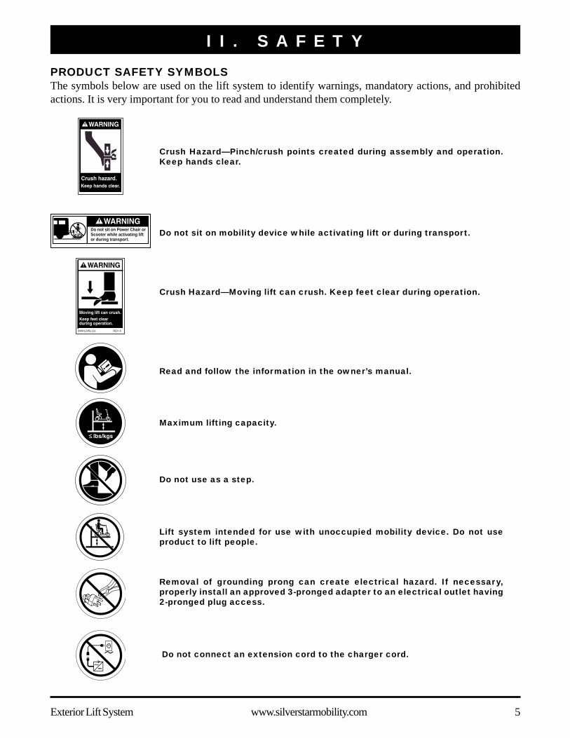
I I . S A F E T YPRODUCT SAFETY SYMBOLSThe symbols below are used on the lift system to identify warnings, mandatory actions, and prohibitedactions. It is very important for you to read and understand them completely.
Removal of grounding prong can create electrical hazard. If necessary,properly install an approved 3-pronged adapter to an electrical outlet having2-pronged plug access.
Do not connect an extension cord to the charger cord.
Read and follow the information in the owner’s manual.
Maximum lifting capacity.
Do not sit on mobility device while activating lift or during transport.
Lift system intended for use with unoccupied mobility device. Do not useproduct to lift people.
Do not use as a step.
Crush Hazard—Pinch/crush points created during assembly and operation.Keep hands clear.
Do not sit on Power Chair orScooter while activating lift or during transport.
Crush Hazard—Moving lift can crush. Keep feet clear during operation.
DWR1235L111 REV A

6 www.silverstarmobility.com Exterior Lift System
Explosive conditions exist!
Do not allow unsupervised children to play near the lift system while the batteries arecharging.
Avoid exposure to rain, snow, ice, salt, or standing water whenever possible. Maintainand store in a clean and dry condition.
Contains Lead.
Wear safety goggles.
I I . S A F E T Y
Disposal and recycling - Contact your authorized Pride Provider for information onproper disposal of your Pride product and its packaging.
Corrosive chemicals contained in battery.
Keep tools and other metal objects away from battery terminals. Contact with toolscan cause electrical shock.

Exterior Lift System www.silverstarmobility.com 7
LIFTING CAPABILITIESThe Exterior Lift System is an electromechanical device designed to lift various types of mobility devices for thepurpose of vehicle transport. The Exterior Lift System is designed for a maximum Class II hitch allowance of190 lbs. (86 kg) and a maximum Class III hitch allowance of 350 lbs. (158 kg). Under no circumstances shouldthe Exterior Lift System be made to exceed this weight limit. Subjecting the lift system to the strain of hoistingmore than it is designed to lift may cause it to fail, resulting in damage to the mobility device and/or injury to thelift operator. Refer to the mobility device owner’s manual for information on the overall weight of the mobilitydevice before lifting.
WARNING! Adding accessories, oversize batteries, or a different seat will increase theweight of your mobility device. Verify with your authorized Pride Provider that the totalweight of your mobility device, including additions, does not exceed the maximum hitchallowance.
INSTALLATIONThe Exterior Lift System is designed to be mounted to a vehicle hitch system. Before lift installation, ensure that thehitch shows no signs of rust or wear and that the front and rear vehicle suspension is acceptable. If any vehiclealterations are necessary, make sure that you fully understand the instructions for drilling or cutting before makingany alterations.
WARNING! Before drilling or cutting into the vehicle, make absolutely certain throughvisual inspection that there are no obstructions in the path of the drill bit, such as the fueltank, exhaust pipes, or electrical wires.
LIFTING NON-PRIDE PRODUCTSThe Exterior Lift System is an extremely versatile device, which users may employ to lift items other than Prideproducts. Pride has no control over such use, nor can Pride anticipate every possible use to which a lift system maybe put. Lifting non-Pride products with the Exterior Lift System is done at the operator’s own risk, and Prideaccepts no liability for damage or injury resulting from such use.
PRELIFT INSPECTIONBefore operating the Exterior Lift System, inspect your surroundings to ensure that the lift system has a clear pathof operation. Remove any possible obstructions before operating the lift and do not allow children to operate orplay near the lift.
OPERATOR POSITIONINGThe operator of the lift should stand a safe distance from the unit being lifted/lowered to ensure that his/her feet arenever positioned under the raised lift platform. The operator should also keep his/her hands clear of the lift systemto avoid the potential for injury.
TRANSPORT VEHICLE POSITIONINGBe sure your vehicle is parked on flat, level ground before attempting to load, lift, or remove a mobility device withthe Exterior Lift System. Make sure the vehicle emergency park brake is engaged before loading or unloading amobility device.
I I . S A F E T Y

8 www.silverstarmobility.com Exterior Lift System
I I . S A F E T Y
WARNING! Adding accessories,oversize batteries, or a differentseat will increase the weight ofyour mobility device. Verify with yourauthorized Pride Provider that thetotal weight of your mobility device,including additions, does notexceed the maximum weightallowance.
WARNING! Never exceed themaximum lifting capacity of a liftregardless of the class of hitch beingused. Doing so may cause lift and/orvehicle damage.
Hitch Classes! A Class I hitch has a maximum tongue weight of
200 lbs. (90 kg).! A Class II hitch has a maximum tongue weight of
350 lbs. (158 kg).! A Class III hitch has a maximum tongue weight
of 500 lbs. (226 kg).! A Class IV hitch has a maximum tongue weight of
1200 lbs. (544 kg).
WARNING! Before installing the(exterior) lift and applicable hitchsystem, check your vehicle owner’smanual for its hitch maximumtongue weight capacity. Do notexceed the maximum tongue weightcapacity of your vehicle.
HITCH CLASS INFORMATIONHitches come in a variety of sizes and are designated by class. The classes range from Class I to Class IV. Aheavier load requires a larger class, which has a higher tongue weight. Tongue weight is the amount of weight(downward force) that the load puts on the hitch. See figure 1.
The combined weight of your lift and mobility device gives you the minimum tongue weight for your application.Exceeding the tongue weight of a hitch creates an unsafe driving situation and can damage the hitch and/or thevehicle. See figures 2 and 3.
Figure 1. Tongue Weight Pressure Point
Figure 2. Unsafe Driving Situation
Figure 3. Vehicle Damage

Exterior Lift System www.silverstarmobility.com 9
EXTERIOR LIFT SYSTEM INSTALLATIONThe Exterior Lift System is designed to be easily installed into any vehicle equipped with a Class II or Class III hitch receiver.The hitch receiver should be installed no higher than 21 in. (53 cm) from the bottom of the hitch tube to the ground.
NOTE: Once installed, the lift system may obstruct the view of the vehicle license plate. Research thelocal laws for license plate obstruction in your area and install the license plate kit. Contact your autho-rized Pride Provider for more information.
WARNING! The Exterior Lift should be installed by an authorized Pride Provider or servicetechnician only.
Follow these steps to install the lock-down arm:1. Lay the lift system flat on the floor.
NOTE: If your lift system is equipped with a permanent threaded stud, removal of the pivot tube andpivot bolt is not necessary for lock-down arm installation. See figure 4.
2. Apply power to the lift until there is enough clearance to remove the pivot bolt. See figure 4.
NOTE: If the pivot bolt does not remove easily, apply power to the lift and make a slight adjustment tothe angle of the pivot tube. Repeat as necessary.
3. Remove the pivot bolt. Keep hardware for reassembly.4. Remove the pivot tube. See figure 4.5. Insert the lift arm securement screw through the countersunk hole of the u-bracket (from the inside out).6. Position the lock-down arm onto the screw and insert the pivot bolt through the u-bracket and lock-down
arm. The pivot bolt is used for alignment purposes at this time.7. Secure the nut to the securement screw and install the cap. Remove the pivot bolt.8. Position the pivot tube onto the u-bracket and reinsert the pivot bolt through the u-bracket, pivot tube, and
lock-down arm.9. Install the nut back onto the pivot bolt and install the cap. Do not overtighten the nut. Ensure the pivot tube
pivots freely without binding.
I I I . I N S T A L L A T I O N
Figure 4. Lock-Down Arm Installation
PIVOT TUBE
LIFT ARM SECUREMENT SCREWPIVOT BOLT
NUT
CAPNUT CAP
LOCK-DOWN ARM
U-BRACKET
THREADEDSTUD

10 www.silverstarmobility.com Exterior Lift System
I I I . I N S T A L L A T I O NFollow these steps to install the Exterior Lift System:1. Remove the preassembled mounting hardware from the
hitch tube.2. Mount the hitch tube to the lift frame using the previously
removed mounting hardware. See figure 5.3. Slide the hitch tube into the vehicle hitch receiver, aligning
the mounting hole closest to the lift with the mounting holein the hitch receiver. See figure 6.
WARNING! Lift system components areheavy. Ask for assistance if necessarywhen attaching the lift frame to the hitchreceiver. Use proper lifting techniques andavoid lifting beyond your capacity.
WARNING! Avoid pinch points! Do not holdthe lift frame by the pivot points whenmounting the lift frame to the hitchreceiver.
4. Secure the hitch tube with the supplied bolt and nut,inserting the bolt from the passenger’s side through tothe driver’s side of the hitch. See figure 6.
WARNING! Threading the bolt from thewrong side or allowing the bolt to turnwhile tightening the nut will dislodge thethreaded insert in the hitch tube.
WARNING! Do not attach a Class II hitchtube to a Class III hitch receiver.
NOTE: Make sure the hitch bolt is tightened firmlybefore securing the nut to the hitch assembly to mini-mize the chance that the lift will tilt during trans-port.
NOTE: Make sure the hitch tube and lift platform areparallel to the ground before operating the lift system.An angled hitch tube may cause unreliable lift opera-tion and/or damage to the lift system.
Figure 5. Hitch Tube Assembly
Figure 6. Lift Frame Vehicle Mounting
HITCH TUBE
LIFT FRAME
HITCH RECEIVER
MOUNTING HARDWARE
5. Route the lift system wiring harness through the vehicle. Refer to “Wiring Harness Installation.”
WARNING! Route the wiring harness through the vehicle rather than under the vehicle toavoid coming in contact with sharp edges, extreme temperatures, moving parts, androadway debris including road salt and other highly corrosive materials. Power shorts mayoccur if wires come in contact with hot exhaust parts or sharp edges.
WARNING! Never attach the wiring harness to a secondary power source. Do not attemptto use trailer wiring to power the lift system. The wiring harness must be connected directlyto the vehicle battery.
Exterior Lift System www.silverstarmobility.com 11
I I I . I N S T A L L A T I O N
NOTE: If your lift is equipped with an onboard battery, refer to “Onboard Battery Installation.”
6. Install the lift platform kit. Refer to the instructions supplied with the kit.7. Install the wheel chocks to the lift platform. Refer to “Wheel Chock Installation.”
Wiring Harness InstallationThe wiring harness is approximately 25 ft. (7.62 meters) long and will accommodate most vehicles.
NOTE: You may wish to perform a practice run before installing the wiring harness. Route a piece oflight rope (equivalent to the gauge of the wiring harness) along the anticipated path observing contactpoints, potential rubbing/chafing points, and any sharp edges. Remove sharp edges with a fine gradefile, then treat the steel with a rust inhibitor or metal sealant.
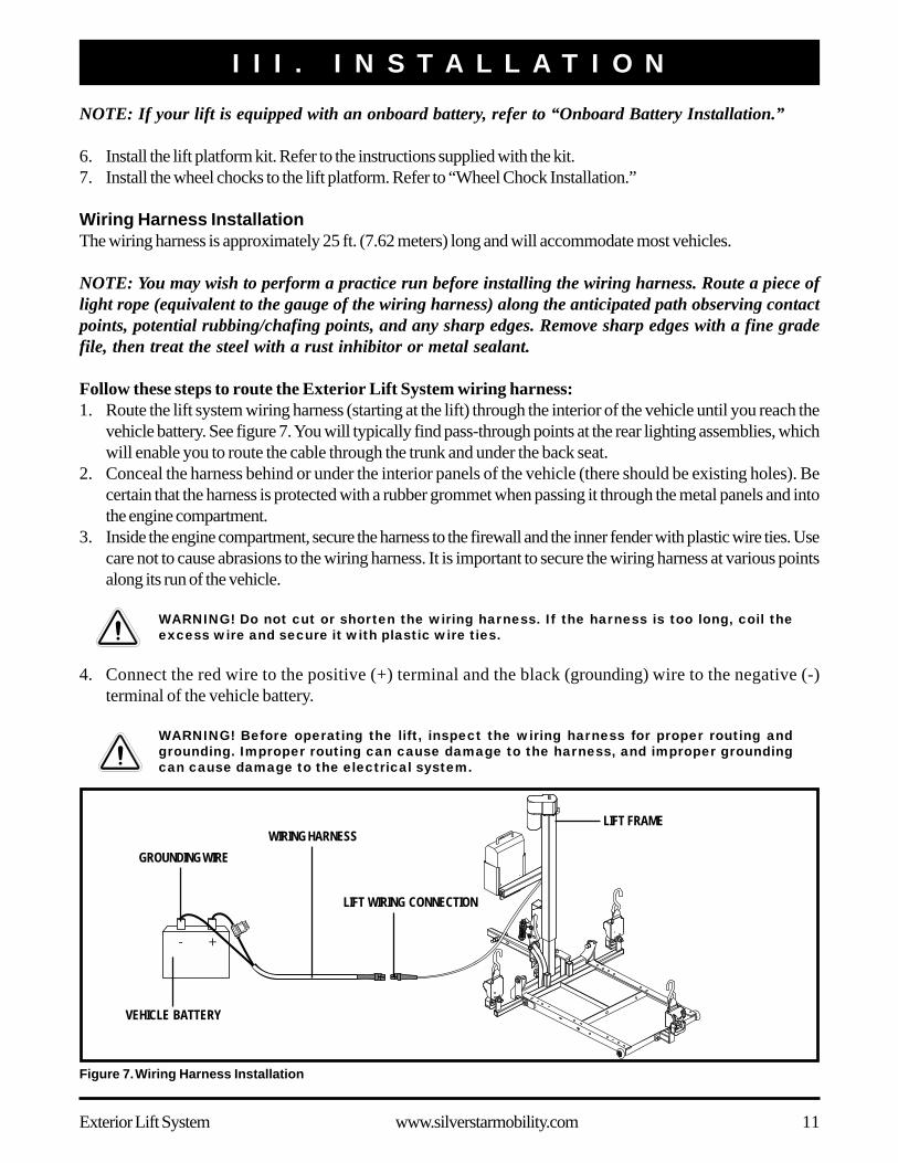
Follow these steps to route the Exterior Lift System wiring harness:1. Route the lift system wiring harness (starting at the lift) through the interior of the vehicle until you reach the
vehicle battery. See figure 7. You will typically find pass-through points at the rear lighting assemblies, whichwill enable you to route the cable through the trunk and under the back seat.
2. Conceal the harness behind or under the interior panels of the vehicle (there should be existing holes). Becertain that the harness is protected with a rubber grommet when passing it through the metal panels and intothe engine compartment.
3. Inside the engine compartment, secure the harness to the firewall and the inner fender with plastic wire ties. Usecare not to cause abrasions to the wiring harness. It is important to secure the wiring harness at various pointsalong its run of the vehicle.
WARNING! Do not cut or shorten the wiring harness. If the harness is too long, coil theexcess wire and secure it with plastic wire ties.
4. Connect the red wire to the positive (+) terminal and the black (grounding) wire to the negative (-)terminal of the vehicle battery.
WARNING! Before operating the lift, inspect the wiring harness for proper routing andgrounding. Improper routing can cause damage to the harness, and improper groundingcan cause damage to the electrical system.
Figure 7. Wiring Harness Installation
VEHICLE BATTERY
WIRING HARNESSLIFT FRAME
LIFT WIRING CONNECTION
GROUNDING WIRE

12 www.silverstarmobility.com Exterior Lift System
I I I . I N S T A L L A T I O N
Onboard Battery InstallationThe optional onboard battery is designed for easy installationas it does not require any wires to be routed through or un-der the vehicle.
Follow these steps to install the onboard battery:1. Align the mounting holes in the battery case bracket with
those in the accessory bracket located under the keyswitch tube. See figure 8.
2. Secure the battery case to the accessory bracket withthe supplied hardware. See figure 8.
3. Insert the onboard battery into the battery case, makingsure that the connector on the bottom of the battery alignsand fully connects with the mating connector inside thebattery case.
4. Plug the battery cord on the bottom of the battery caseinto the mating connector running from the motor. Seefigure 8.
Wheel Chock InstallationYour lift is supplied with four adjustable wheel chocks, thatwhen installed, aid in centering your mobility device duringloading.
Follow these steps to install the wheel chocks:1. Drive your mobility device onto the lift platform, posi-
tioning it as near to the center as possible.2. Position the wheel chocks on the platform.
Figure 8. Onboard Battery Installation
BATTERY CASEBRACKET
ACCESSORY BRACKET
BATTERY CASE
Figure 9. Wheel Chock Installation
WHEEL CHOCKTOP
WHEEL CHOCKBOTTOM
SCREWS
Scooters: Place a wheel chock in front of the frontwheel(s) and behind the rear wheels.Power chairs: Place a wheel chock in front of the drivewheels and behind the rear casters.
3. Take note of the adjustment holes the wheel chocks alignwith on the platform and remove the chocks.
4. Remove the mobility device from the lift platform.5. Raise the platform high enough to be able to install hard-
ware from beneath it.6. Position the wheel chock bottom on the underside of the
platform, aligning it with the wheel chock top. See figure 9.7. Secure the wheel chock sections to the platform using
the supplied hardware. See figure 9.8. Repeat these steps to install the remaining wheel chocks
to the lift platform.

Exterior Lift System www.silverstarmobility.com 13
I V . O P E R A T I O NEXTERIOR LIFT SYSTEM OPERATION
WARNING! The Exterior Lift System is intended for the transport of mobility devices only.The mobility device must be unoccupied before operating the lift.
WARNING! Do not exceed the load limits of your vehicle or hitch system as specified bythe vehicle manufacturer.
WARNING! Use extreme caution when driving with the lift installed on your vehicle. Beaware that the lift extends away from the back of the vehicle and extra clearance isneeded when backing up, turning, parking, or driving through driveway entrances/exits.Drive slowly when negotiating pot holes, road bumps, and railroad tracks.
Figure 10. Key Switch Operation
Follow these steps to operate the Exterior Lift System:1. Insert the key into the key switch.2. Turn and hold the key clockwise to lower the lift plat-
form. See figure 10. Release the key as soon as the liftplatform touches the ground.
3. Set the speed control of the mobility device to the slow-est setting and carefully drive your mobility device ontothe lift platform, being sure to center the mobility deviceon the platform to the best of your ability.
NOTE: You may wish to load the mobility device whilestanding next to it using the manual freewheel feature.Refer to the mobility device owner’s manual for moreinformation on manual freewheel mode.
WARNING! If the lift is equipped with anautomatic lock-down arm, load themobility device (scooter) onto the liftplatform from the driver’s side of thevehicle to ensure proper contact of theautomatic lock-down arm with the scooterfloorboard. Loading the scooter from thepassenger side will cause the automaticlock-down arm to interfere with thescooter seat when the platform is raised.
WARNING! If the lift is equipped with thepower dock option, the mobility devicemust be loaded and unloaded from thedriver’s side of the vehicle. Loading themobility device from the passenger sidewill not allow for proper securement ofthe device to the power dock adapter.
4. Shut down the power to the mobility device, remove thekey if applicable, and make sure the unit is in drive mode(drive motors engaged). Refer to the mobility deviceowner’s manual for more information on drive mode.
Figure 11. Retractable Tie-down Strap
HOOK
RELEASE LEVER
ADJUSTMENTLEVER
14 www.silverstarmobility.com Exterior Lift System
I V . O P E R A T I O N
WARNING! For lift systems equipped withthe automatic lock-down arm, do notattempt to adjust the pressure of thearm. This feature has been configuredby your authorized Pride Provider to meetyour needs and requires no furtheradjustment.
WARNING! If your scooter is equippedwith pneumatic drive tires, make surethe tires are inflated to the recommendedpressure labeled on the tire sidewall. Thiswill ensure that the scooter is at thecorrect deck height for proper lock-downarm positioning.
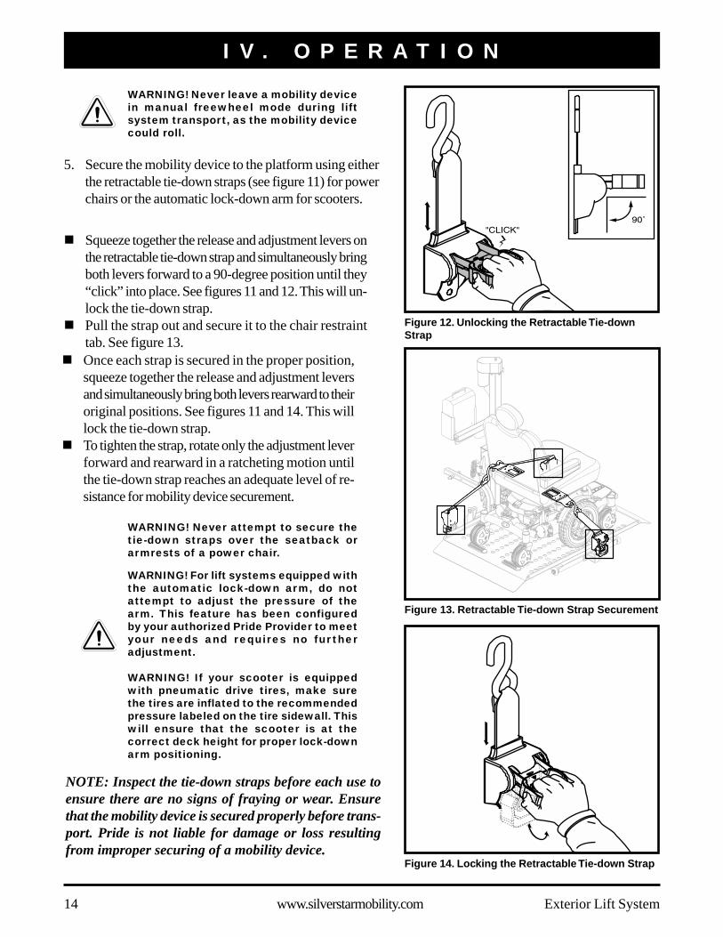
Figure 12. Unlocking the Retractable Tie-downStrap
WARNING! Never attempt to secure thetie-down straps over the seatback orarmrests of a power chair.
! Once each strap is secured in the proper position,squeeze together the release and adjustment leversand simultaneously bring both levers rearward to theiroriginal positions. See figures 11 and 14. This willlock the tie-down strap.
! To tighten the strap, rotate only the adjustment leverforward and rearward in a ratcheting motion untilthe tie-down strap reaches an adequate level of re-sistance for mobility device securement.
Figure 14. Locking the Retractable Tie-down Strap
Figure 13. Retractable Tie-down Strap Securement
WARNING! Never leave a mobility devicein manual freewheel mode during liftsystem transport, as the mobility devicecould roll.
5. Secure the mobility device to the platform using eitherthe retractable tie-down straps (see figure 11) for powerchairs or the automatic lock-down arm for scooters.
! Squeeze together the release and adjustment levers onthe retractable tie-down strap and simultaneously bringboth levers forward to a 90-degree position until they“click” into place. See figures 11 and 12. This will un-lock the tie-down strap.
! Pull the strap out and secure it to the chair restrainttab. See figure 13.
NOTE: Inspect the tie-down straps before each use toensure there are no signs of fraying or wear. Ensurethat the mobility device is secured properly before trans-port. Pride is not liable for damage or loss resultingfrom improper securing of a mobility device.

Exterior Lift System www.silverstarmobility.com 15
I V . O P E R A T I O N
MANUAL CRANK
MOTOR HOUSING
Figure 15. Manual Crank Operation
NOTE: Pay attention to the path of the lift platform during operation. Make sure the lift does not rubagainst or interfere with the vehicle in any way. If you notice any contact between the lift platform andthe vehicle, stop lift operation immediately and contact your authorized Pride Provider for assistance.
NOTE: The motor will stop automatically at the top of its stroke and will emit a clicking sound. Release thekey immediately upon hearing this sound, then turn the key counterclockwise one more time for no morethan 2 seconds to ensure the platform is in the fully raised position.
MANUAL EXTERIOR LIFT OPERATIONThe lift system is equipped with a manual crank that serves asbackup in the event of a power failure. Using the suppliedtool, rotate the manual crank (located on top of the motorhousing) clockwise or counterclockwise to move the plat-form up or down. See figure 15.
WARNING! Do not attempt to manually pull the lift platform down from the stowed position.Doing so will result in product damage and will void the product warranty.
Follow these steps to remove a mobility device from the Exterior Lift System:1. Lower the lift platform to the ground.2. Unfasten the tie-down straps or allow the lock-down arm to automatically return to the vertical position.
3. Unload the mobility device from the lift platform.4. Raise the lift platform for storage, noting that it will automatically fold into a stowed position.5. Remove the key from the lift system when it is not in use.
! Unlock and loosen the tie-down straps.! Rotate the adjustment lever only on each strap forward and rearward in a ratcheting motion until each strap
reaches its original furled position.
6. Turn and hold the key counterclockwise to raise the lift. See figure 10. Continue to raise the lift until the motorstops, then release the key.
NOTE: As the lift platform rises, the automatic lock-down arm activates to secure the scooter to the liftplatform. You may need to adjust the scooter’s tiller position to prevent interference with the smoothoperation of the automatic lock-down arm.

16 www.silverstarmobility.com Exterior Lift System
PROHIBITED! Removal of the grounding prong can create an electrical hazard. If necessary,properly install an approved 3-pronged adapter to an electrical outlet having 2-prongedplug access.
PROHIBITED! Do not allow unsupervised children to play near the lift system or batterycharger while the battery is charging.
PROHIBITED! Do not expose the battery charger to rain or other sources of moistureunless it has been tested for outdoor use. Refer to the manual supplied with the batterycharger for more information.
WARNING! Explosive gases may be generated while charging the battery. Keep the batteryand the battery charger away from sources of ignition such as flames or sparks and provideadequate ventilation when charging the battery.
WARNING! Do not attempt to charge the battery and operate the lift system at the sametime.
WARNING! Do not attempt to wire the lift system directly to the vehicle battery if the liftsystem is equipped with an onboard battery.
WARNING! You must recharge the lift system battery with the supplied battery charger. Donot use an automotive-type battery charger.
WARNING! If the battery is exposed to adverse or extreme weather conditions, then itmust be allowed to adjust to the difference in environmental conditions before beingcharged.
WARNING! Inspect the battery charger, wiring, and connectors for damage before eachuse. Contact your authorized Pride Provider if damage is found.
WARNING! Do not attempt to open the battery charger case. If the battery charger doesnot appear to be working correctly, contact your authorized Pride Provider.
BATTERY CHARGINGFollow these steps to charge the onboard battery:1. Remove the onboard battery from the battery case and
place it near a standard electrical outlet.2. Plug the charger cord into the mating socket located on
the bottom of the battery case, then connect the chargercord to a standard electrical outlet. See figure 16.
NOTE: It is recommended that you replace the batteryevery 3–5 years. Store the battery in a moisture-freeenvironment when not in use.
MANDATORY! Read the battery charginginstructions in this manual and in themanual supplied with the battery chargerbefore charging the battery.
V . B A T T E R Y C H A R G I N G
Figure 16. Battery Charging
PROHIBITED! Never use an extension cord to plug in your charger cord. Plug the chargercord directly into a properly wired standard electrical outlet.

Exterior Lift System www.silverstarmobility.com 17
NOTE: If you encounter a damaged or cracked battery, immediately enclose it in a plastic bag andcontact your local waste disposal agency or your authorized Pride Provider for instructions on disposaland battery recycling, which is our recommended course of action.
Follow these steps to replace the onboard battery(figure 17):1. Unfasten the battery securement strap located at
the bottom of the battery box.2. Remove the hardware from the battery securement
bracket and remove the bracket.3. Remove the hardware from the battery connector.4. Slide the battery out of the battery box to expose
the battery harness.5. Disconnect the battery harnesses from the battery
terminals.6. Connect the battery harnesses to the new battery.7. Slide the new battery into the battery box.8. Reinstall the hardware to secure the battery con-
nector and tighten.9. Reinstall the battery securement bracket and tighten
the hardware.10. Refasten the battery securement strap.
BATTERY SECUREMENT STRAP
BATTERY BOX
BATTERY SECUREMENT BRACKET
BATTERY CONNECTOR
V . B A T T E R Y C H A R G I N G
Figure 17. Battery Replacement
BATTERY REPLACEMENT
WARNING! Battery posts, terminals, and related accessories contain lead andlead compounds. Wear goggles and wash hands after handling.
MANDATORY! Use only AGM or Gel-Cell batteries to reduce the risk of leakageor explosive conditions.
WARNING! Corrosive chemicals contained in battery.
WARNING! Contact with tools can cause electrical shock.
WARNING! Connect the battery harnesses in the proper manner. RED (+) cablesmust be connected to positive (+) battery terminals/posts. BLACK (-) cablesmust be connected to negative (-) battery terminals/posts. REPLACE cablesimmediately if damaged. Protective caps must be installed over all batteryterminals.
18 www.silverstarmobility.com Exterior Lift System
V I . C A R E A N D M A I N T E N A N C E
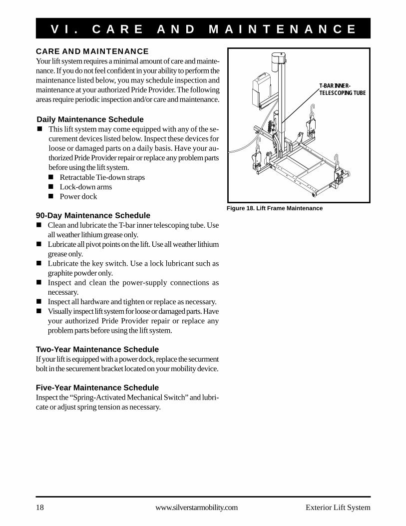
CARE AND MAINTENANCEYour lift system requires a minimal amount of care and mainte-nance. If you do not feel confident in your ability to perform themaintenance listed below, you may schedule inspection andmaintenance at your authorized Pride Provider. The followingareas require periodic inspection and/or care and maintenance.
T-BAR INNER-TELESCOPING TUBE
Figure 18. Lift Frame Maintenance
Daily Maintenance Schedule! This lift system may come equipped with any of the se-
curement devices listed below. Inspect these devices forloose or damaged parts on a daily basis. Have your au-thorized Pride Provider repair or replace any problem partsbefore using the lift system.! Retractable Tie-down straps! Lock-down arms! Power dock
90-Day Maintenance Schedule! Clean and lubricate the T-bar inner telescoping tube. Use
all weather lithium grease only.! Lubricate all pivot points on the lift. Use all weather lithium
grease only.! Lubricate the key switch. Use a lock lubricant such as
graphite powder only.! Inspect and clean the power-supply connections as
necessary.! Inspect all hardware and tighten or replace as necessary.! Visually inspect lift system for loose or damaged parts. Have
your authorized Pride Provider repair or replace anyproblem parts before using the lift system.
Two-Year Maintenance ScheduleIf your lift is equipped with a power dock, replace the securmentbolt in the securement bracket located on your mobility device.
Five-Year Maintenance ScheduleInspect the “Spring-Activated Mechanical Switch” and lubri-cate or adjust spring tension as necessary.
Exterior Lift System www.silverstarmobility.com 19
V I . C A R E A N D M A I N T E N A N C E
General Cleaning GuidelinesThe lift system can be hand washed along with the vehicle with soap and water. However, automatic drive-throughcar washes should be avoided as they may interfere with and cause damage to the lift.
Wiring HarnessThe wiring harness should be checked periodically for corrosion and/or decay. Contact your authorized PrideProvider if the wiring harness needs to be replaced.
Lift Platform/Metal Components! Check the lift platform for wear or damage. Contact your authorized Pride Provider for repair or replacement.! The lift platform surface may become slippery if exposed to moisture (ice, snow, rain, mist/spray conditions,
etc.). Use caution when loading/unloading a mobility device in these conditions and wipe off any excessmoisture from the lift platform.
! Regularly inspect the metal lift components for scratches. Treat any problem areas with a rust inhibitor or metalsealant.
If your lift system is exhibiting wear that you feel is questionable in any way, contact your authorized Pride Providerimmediately. Do not attempt to repair, adjust, or modify the manufacturer settings and materials.
Lift Removal! Raise platform to stowed position.! Disconnect power source.! Lubricate hitch mount bolt with WD-40 prior to removal.
20 www.silverstarmobility.com Exterior Lift System
V I I . T R O U B L E S H O O T I N G
TROUBLESHOOTINGAny electromechanical device occasionally requires some troubleshooting. However, most of the problems thatmay arise can usually be solved with a bit of thought and common sense. Many of these problems occur becausethe battery is not fully charged or because the battery is worn down and can no longer hold a charge.
What if the motor on my lift system will not operate?! Make sure the onboard battery or vehicle battery is fully charged.! Make sure all connections to the motor and battery are secure.! Check the wiring harness for signs of wear or decay. Replace the harness if necessary.
What if the lift system operates slowly up or down?! Make sure the onboard battery or vehicle battery is fully charged.! Make sure all connections to the motor and battery are secure.! Check the wiring harness for signs of wear or decay. Replace the harness if necessary.
What if the lift platform does not fold into the stowed position?Check to make sure there are no obstructions in the T-bar pivot points.
What if the lift platform does not lower completely to the ground?! Verify that the hitch receiver is at the proper height. The distance from the bottom of the hitch to the ground
should not exceed 21 in. (53 cm).! Check to make sure that the area under the lift platform is free from obstructions.
What if the lift bottoms out when driving over bumps or driveway entrances?Verify that the hitch receiver is at the proper height. The distance from the bottom of the hitch to the ground shouldbe 21 in. (53 cm).

Exterior Lift System www.silverstarmobility.com 21
V I I I . W A R R A N T Y
THREE-YEAR TRANSFERABLE LIMITED WARRANTYFor three (3) years from the date of purchase, Pride Mobility Products will repair or replace at our option, free ofcharge, any mechanical or electrical component found upon examination by an authorized representative of Prideto be defective in material and/or workmanship.
This warranty does not extend to those items that may require replacement due to normal wear and tear.
! Labor, service calls, shipping, and other charges incurred for repair of the product, unless specifically autho-rized by Pride Mobility Products Corporation IN ADVANCE, are excluded.
Exclusions also include components with damage caused by:! Contamination! Abuse, misuse, accident, or negligence! Battery fluid spillage or leakage! Commercial use, or use other than normal! Improper operation, maintenance, or storage! Repairs and/or modifications made to any part without specific consent from Pride Mobility Products Corpo-
ration.! Circumstances beyond the control of Pride
ONE-YEAR WARRANTYThe battery is covered by a separate one (1) year warranty provided by the battery manufacturer. The batteriesare not warranted by Pride Mobility Products Corporation.
SERVICE CHECKS AND WARRANTY SERVICEAn authorized Pride Mobility Products Provider must perform warranty service. Do not return faulty parts to PrideMobility Products without prior written authorization. All transportation costs and shipping damage incurred whilesubmitting parts for repair or replacement is the responsibility of the purchaser.
Failure to follow the instructions, warnings, and notes in the owner’s manual and those located on your Pride liftproduct can result in personal injury or product damage and will void Pride’s product warranty.
There is no other express warranty.
IMPLIED WARRANTIESImplied warranties, including those of merchantability and fitness for a particular purpose, are limited to one (1)year from the date of purchase and to the extent permitted by law. Any and all implied warranties are excluded.This is the exclusive remedy. Liabilities for consequential damages under any and all warranties are excluded.
Some states do not allow limitations on how long an implied warranty lasts or do not allow the exclusion oflimitation incidental or consequential damages. The above limitation or exclusion may not apply to you.
This warranty gives you specific rights, and you may also have other rights, which vary from state to state.
Please fill out and return the product registration card to Pride Mobility Products. This will aid Pride in providingthe best possible technical and customer service.

22 www.silverstarmobility.com Exterior Lift System
A P P E N D I X I - S P E C I F I C A T I O N S
SPECIFICATIONSLift System Dimensions: Overall Height: 58 in. (147 cm)
Overall Width: 41–44 in. (104–112 cm) from hitch with platform down
20 in. (51 cm) from hitch with platform folded
Platform Width:28 in. (71 cm)
Maximum Lift Capacity: 190 lbs. (86 kg) with Class II hitch
350 lbs. (158 kg) with Class III or higher hitch
Maximum Mobility 27 in. (68.58 cm)
Device Width:
Maximum Hitch-to- 21 in. (53 cm)
Ground Clearance:
Motor: Fully sealed, 12-volt DC
Onboard Battery: 12-volt, 18 Ah
Charger: 110-volt, off-board

*INFMANU3279*