Product name: Module 68 Product-ID: 1040579...5.1 Lubrication of guide carriage ... 7.4 Module 68...
38
Original version EN | Translation of the original instructions IEF-Werner GmbH | Wendelhofstraße 6 | DE-78120 Furtwangen | www.ief-werner.de Operating instructions Product name: Module 68 Product-ID: 1040579
Transcript of Product name: Module 68 Product-ID: 1040579...5.1 Lubrication of guide carriage ... 7.4 Module 68...
Original version EN | Translation of the original instructions
IEF-Werner GmbH | Wendelhofstraße 6 | DE-78120 Furtwangen | www.ief-werner.de
Operating instructions
Product name: Module 68 Product-ID: 1040579


Module 68 Operating instructions 3 - 38
IEF-Werner GmbH | Wendelhofstraße 6 | DE-78120 Furtwangen | www.ief-werner.de
Erst
ellt
von:
Fra
nk R
eich
elt
| M
AN
_EN
_104
0579
_Mod
ule
68_R
2f.d
oc
Use
■ The operating instructions must be available near by the component at all times.
■ The operating instructions are an integral part of the component / device.
■ Always use the complete original (or the original translation) of these operating instructions.
Supplier & Manufacturer
IEF-Werner GmbH
Wendelhofstraße 6
DE-78120 Furtwangen
Phone: +49 7723-925-0
Fax: +49 7723-925-100
www.ief-werner.de
Service
Find your IEF service station on our website:
■ http://www.ief-werner.de
Legal information
All rights, including translation, reserved. No part of the work must be reproduced in any manner (print, copy, microfilm or other method) without the written consent of IEF-Werner GmbH or processed, reproduced or distributed using electronic systems.
All rights reserved for the case of patent, utility sample or design patent entry reserved.
Changes reserved.
© May 2019, IEF-Werner GmbH, printed in Germany
Module 68 4 - 38 Operating instructions
IEF-Werner GmbH | Wendelhofstraße 6 | DE-78120 Furtwangen | www.ief-werner.de
Erst
ellt
von:
Fra
nk R
eich
elt
| M
AN
_EN
_104
0579
_Mod
ule
68_R
2f.d
oc
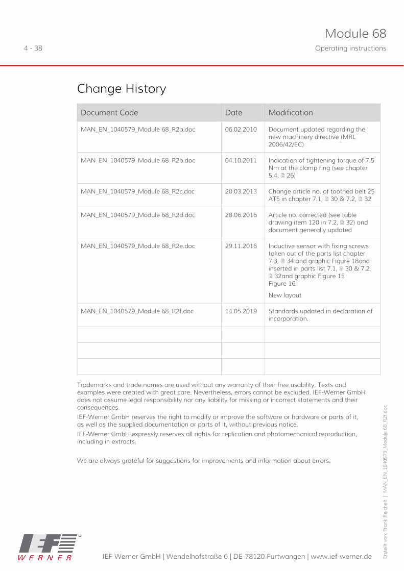
Change History
Document Code Date Modification
MAN_EN_1040579_Module 68_R2a.doc 06.02.2010 Document updated regarding the new machinery directive (MRL 2006/42/EC)
MAN_EN_1040579_Module 68_R2b.doc 04.10.2011 Indication of tightening torque of 7.5 Nm at the clamp ring (see chapter 5.4, 26)
MAN_EN_1040579_Module 68_R2c.doc 20.03.2013 Change article no. of toothed belt 25 AT5 in chapter 7.1, 30 & 7.2, 32
MAN_EN_1040579_Module 68_R2d.doc 28.06.2016 Article no. corrected (see table drawing item 120 in 7.2, 32) and document generally updated
MAN_EN_1040579_Module 68_R2e.doc 29.11.2016 Inductive sensor with fixing screws taken out of the parts list chapter 7.3, 34 and graphic Figure 18and inserted in parts list 7.1, 30 & 7.2, 32and graphic Figure 15 Figure 16
New layout
MAN_EN_1040579_Module 68_R2f.doc 14.05.2019 Standards updated in declaration of incorporation.
Trademarks and trade names are used without any warranty of their free usability. Texts and examples were created with great care. Nevertheless, errors cannot be excluded. IEF-Werner GmbH does not assume legal responsibility nor any liability for missing or incorrect statements and their consequences.
IEF-Werner GmbH reserves the right to modify or improve the software or hardware or parts of it, as well as the supplied documentation or parts of it, without previous notice.
IEF-Werner GmbH expressly reserves all rights for replication and photomechanical reproduction, including in extracts.
We are always grateful for suggestions for improvements and information about errors.

Module 68 Operating instructions 5 - 38
IEF-Werner GmbH | Wendelhofstraße 6 | DE-78120 Furtwangen | www.ief-werner.de
Erst
ellt
von:
Fra
nk R
eich
elt
| M
AN
_EN
_104
0579
_Mod
ule
68_R
2f.d
oc
Table of Contents
1 Declaration of incorporation .................................................................................... 7
2 Safety ........................................................................................................................... 9 2.1 Definition of Warning Notes ................................................................................................. 9 2.2 General Warning Notes ....................................................................................................... 10 2.2.1 Special Hazard Warnings .............................................................................................. 11
3 Intended Use ............................................................................................................ 13 3.1 Reasonably foreseeable misuse ........................................................................................ 13
4 Assembly Instructions ............................................................................................. 15 4.1 Installation Position .............................................................................................................. 15 4.2 Overview of motor installation variants ........................................................................... 15 4.3 Attachment ............................................................................................................................ 16 4.4 Installation of actuators ...................................................................................................... 17 4.5 Wiring ..................................................................................................................................... 18 4.5.1 Motors ............................................................................................................................... 18 4.5.2 Initiators ............................................................................................................................ 18 4.5.3 Technical Data of Initiators ........................................................................................... 19 4.5.4 Limit Switch ...................................................................................................................... 20 4.5.5 Technical Data ................................................................................................................. 21 4.5.6 Tightening Torques for Screw Connections ................................................................ 21 4.5.7 Technical Data of the Linear Module 68 ..................................................................... 21 4.5.8 Cable routing ................................................................................................................... 22 4.5.9 Type plate ......................................................................................................................... 23 4.5.10 Technical Data when using a Planetary Gear ............................................................ 24
5 Maintenance and Repair ........................................................................................ 25 5.1 Lubrication of guide carriage ............................................................................................. 25 5.2 Tooth belt tension ................................................................................................................ 25 5.3 Belt tension gear toothed belt ........................................................................................... 25 5.4 Drive unit ................................................................................................................................ 26
6 Troubleshooting ....................................................................................................... 27
7 Parts lists and drawings ......................................................................................... 30 7.1 Module 68, TG1000018, Installation variant 1 ................................................................ 30 7.2 Module 68, TG1000018, installation variants 2 and 3 ................................................... 32 7.3 Carriage Module 68, Part no. 526820 ............................................................................... 34

Module 68 6 - 38 Operating instructions
IEF-Werner GmbH | Wendelhofstraße 6 | DE-78120 Furtwangen | www.ief-werner.de
Erst
ellt
von:
Fra
nk R
eich
elt
| M
AN
_EN
_104
0579
_Mod
ule
68_R
2f.d
oc
7.4 Module 68 gearbox, TG 1000032 ...................................................................................... 36 7.5 Clamping block complete, Part No. 525796 .................................................................... 38 7.6 Clamping block complete, Part No. 525181 .................................................................... 38

Module 68 Operating instructions 7 - 38
IEF-Werner GmbH | Wendelhofstraße 6 | DE-78120 Furtwangen | www.ief-werner.de
Erst
ellt
von:
Fra
nk R
eich
elt
| M
AN
_EN
_104
0579
_Mod
ule
68_R
2f.d
oc
1 Declaration of incorporation EC declaration of incorporation in the sense of the EC directive 2006/42/EC (machinery), Annex II B
The manufacturer:
IEF-Werner GmbH
Wendelhofstraße 6
78120 Furtwangen – Germany
hereby declares that the following products (the incomplete machine/component):
Designation IEF-Werner parts group number
Module 68 TG1000018
where possible based on the scope of delivery, correspond to the following basic requirements of the directive on Machinery (2006/42/EC):
Annex I, item: 1.1.2; 1.1.3; 1.1.5; 1.3.2; 1.3.4; 1.5.1; 1.7.3; 1.7.4;
The incomplete machine also corresponds to the following further directives:
■ Directive 2014/30/EU of the council, dated 15 December 2004, for harmonisation of the legal provisions of the member states on electromagnetic compatibility.
■ Directive 2014/35/EU of the council, dated 12 December 2006, for harmonisation of the legislation of the member states regarding electrical equipment for use within specified voltage thresholds.
The technical documents were generated according to Annex VII part B and may be electronically submitted to the national authorities upon justified request.
List of some applied harmonised standards:
■ EN ISO 12100-1,-2 / EN ISO 13857 / EN ISO 13850 / EN 60201-1
Commissioning of the incomplete machine (component/device) delivered by us is not permitted until it has been determined that the overall system into which the component is installed meets the basic safety and health protection requirements according to Annex I of the above EC directive 2006/42/EC.
Name and address of the documentation officer: IEF-Werner GmbH
Furtwangen, May 2019 Stefan Deck (Manager)


Module 68 Operating instructions 9 - 38
IEF-Werner GmbH | Wendelhofstraße 6 | DE-78120 Furtwangen | www.ief-werner.de
Erst
ellt
von:
Fra
nk R
eich
elt
| M
AN
_EN
_104
0579
_Mod
ule
68_R
2f.d
oc
2 Safety
2.1 Definition of Warning Notes
DANGER
Indicates danger.
Non-observance of the safety provisions causes death.
WARNING
Indicates potential danger.
Non-observance of the safety provisions may cause death or severe injury.
CAUTION
Indicates potential danger.
Non-observance of the safety provisions may cause injury.
NOTICE
Indicates potential danger.
Non-observance of the safety provisions may cause property damage.

Module 68 10 - 38 Operating instructions
IEF-Werner GmbH | Wendelhofstraße 6 | DE-78120 Furtwangen | www.ief-werner.de
Erst
ellt
von:
Fra
nk R
eich
elt
| M
AN
_EN
_104
0579
_Mod
ule
68_R
2f.d
oc
2.2 General Warning Notes
The Module 68 must only be commissioned by specialists who have received safety-technical instructions and are able to assess potential dangers.
Furthermore, all chapters of these operating instructions must have been read and understood completely.
DANGER
Warning of dangerous electrical voltage.
The system must be powered down for all assembly, disassembly or repair work. Non-observance of the safety provisions may cause death.
WARNING
Linear modules must only be operated with their protective device/s.
Linear modules always have to be operated in connection with suitable safety devices (e.g., safety cell, protective room, protective housing, light curtain).
CAUTION
Warning of hot surface.
During operation, the heated drive, in particular of stepper motors may cause skin burns when touched. Install a protective device, if possible! Do not touch the marked areas or wait for an adequate cooling time.
CAUTION
Do not remove plugs or clamps when live.
Motor connectors or clamps must not be inserted or disconnected when live. Risk of burning of the contacts and risk of flying sparks.

Module 68 Operating instructions 11 - 38
IEF-Werner GmbH | Wendelhofstraße 6 | DE-78120 Furtwangen | www.ief-werner.de
Erst
ellt
von:
Fra
nk R
eich
elt
| M
AN
_EN
_104
0579
_Mod
ule
68_R
2f.d
oc
2.2.1 Special Hazard Warnings
In addition, this Original User’s Manual also contains the following special hazard warning:
WARNING
Danger from crushing of limbs.
These points of the components pose the danger of crushing limbs in operation.
Figure 1 Dangers on Module 68


Module 68 Operating instructions 13 - 38
IEF-Werner GmbH | Wendelhofstraße 6 | DE-78120 Furtwangen | www.ief-werner.de
Erst
ellt
von:
Fra
nk R
eich
elt
| M
AN
_EN
_104
0579
_Mod
ule
68_R
2f.d
oc
3 Intended Use The linear unit Module 68 and Module 68 D (rotating unit) are precise, linear adjustment units with toothed belt drive that are used in the commercial area as an attachment part in connection with other components.
In combination with many standardised installation elements and other linear modules of IEF-Werner GmbH (e.g. easyLINE, module 105, module 105 S and module 142, module 142 S), complex multi-axis handling systems can be developed as well.
The areas of application of module 68 or module 68 D are accordingly diverse.
They range from:
■ Stop adjustment in the wood industry
■ Automated assembly lines
■ Joining and press in processes in precision engineering
■ Loading and unloading station of machine tools up to
■ Manipulators for the packaging industry
Figure 2 Linear unit Module 68
3.1 Reasonably foreseeable misuse
The linear module 68 is not to be used for certain applications such as the transport of persons and animals or as a pressing/bending device for cold working of metal.
Use of the linear module without additional measures is also not possible in special fields of application, such as the chemical or food industry or in explosive atmospheres.
In case of doubt, consult the manufacturer.

Module 68 Operating instructions 15 - 38
IEF-Werner GmbH | Wendelhofstraße 6 | DE-78120 Furtwangen | www.ief-werner.de
Erst
ellt
von:
Fra
nk R
eich
elt
| M
AN
_EN
_104
0579
_Mod
ule
68_R
2f.d
oc
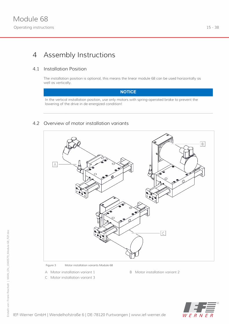
4 Assembly Instructions
4.1 Installation Position
The installation position is optional, this means the linear module 68 can be used horizontally as well as vertically.
NOTICE
In the vertical installation position, use only motors with spring-operated brake to prevent the lowering of the drive in de-energized condition!
4.2 Overview of motor installation variants
Figure 3 Motor installation variants Module 68
A Motor installation variant 1 B Motor installation variant 2
C Motor installation variant 3

Module 68 16 - 38 Operating instructions
IEF-Werner GmbH | Wendelhofstraße 6 | DE-78120 Furtwangen | www.ief-werner.de
Erst
ellt
von:
Fra
nk R
eich
elt
| M
AN
_EN
_104
0579
_Mod
ule
68_R
2f.d
oc
4.3 Attachment
Module 68 and module 68 D are generally attached to the carriage.
The basic body moves freely. Special connections screws (see Figure 5, below) are provided for attachment.
Figure 4 Assembly drilling template Module 68
Figure 5 Connection screw
A Connection screw M6 for Module 68

Module 68 Operating instructions 17 - 38
IEF-Werner GmbH | Wendelhofstraße 6 | DE-78120 Furtwangen | www.ief-werner.de
Erst
ellt
von:
Fra
nk R
eich
elt
| M
AN
_EN
_104
0579
_Mod
ule
68_R
2f.d
oc
4.4 Installation of actuators
Actuators (pick-up modules, cylinders, etc.) to be installed on the Module 68 are usually attached to the linear unit using the drill template (see Figure 6, below) on the end plates.
For module 68 D a shaft stub is available (see Figure 7, below).
Figure 6 Drilling template of the end plate Module 68
Figure 7 Shaft stub, Module 68 D
A Mounting hole = Ø 4 mm

Module 68 18 - 38 Operating instructions
IEF-Werner GmbH | Wendelhofstraße 6 | DE-78120 Furtwangen | www.ief-werner.de
Erst
ellt
von:
Fra
nk R
eich
elt
| M
AN
_EN
_104
0579
_Mod
ule
68_R
2f.d
oc
4.5 Wiring
4.5.1 Motors
NOTICE
The electrical connection of the motors is performed according to the motor data sheet.
For customer-specific motors, the data sheet must be requested from the respective manufacturer and the motor connected accordingly.
4.5.2 Initiators
Inductive proximity switches (PNP normally closed) are used as standard stroke limitation switches.
NOTICE
The stroke limitation switches are not safety limitation switches according EN60204-1.
The initiators and their supply lines are protected in the carriage or, for the rotating unit (Module 68 D), in the motor flange cover of the rotating unit drive.
The respective connections are centrally connected to one plug. If an additional reference point switch is required, it must be installed externally in a suitable position.
Figure 8 Dimension drawing of initiator
Figure 9 Connection designation PNP normally closed contact
Module 68 Operating instructions 19 - 38
IEF-Werner GmbH | Wendelhofstraße 6 | DE-78120 Furtwangen | www.ief-werner.de
Erst
ellt
von:
Fra
nk R
eich
elt
| M
AN
_EN
_104
0579
_Mod
ule
68_R
2f.d
oc
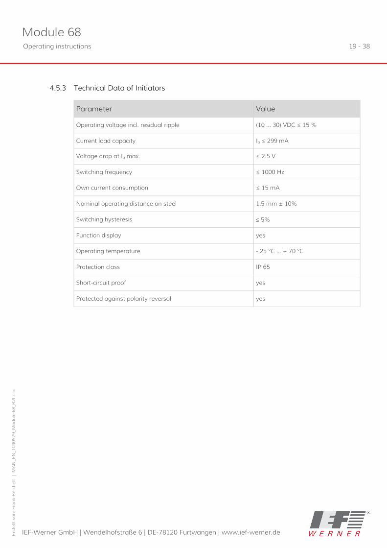
4.5.3 Technical Data of Initiators
Parameter Value
Operating voltage incl. residual ripple (10 … 30) VDC ≤ 15 %
Current load capacity Ia ≤ 299 mA
Voltage drop at Ia max. ≤ 2.5 V
Switching frequency ≤ 1000 Hz
Own current consumption ≤ 15 mA
Nominal operating distance on steel 1.5 mm ± 10%
Switching hysteresis ≤ 5%
Function display yes
Operating temperature - 25 °C … + 70 °C
Protection class IP 65
Short-circuit proof yes
Protected against polarity reversal yes

Module 68 20 - 38 Operating instructions
IEF-Werner GmbH | Wendelhofstraße 6 | DE-78120 Furtwangen | www.ief-werner.de
Erst
ellt
von:
Fra
nk R
eich
elt
| M
AN
_EN
_104
0579
_Mod
ule
68_R
2f.d
oc
4.5.4 Limit Switch
The limit position switch is assigned as follows:
Pin-No. Assignment IEF-Werner cables
1 + 24 V brown
2 Limit switch negative direction green
3 0 V white
4 Limit switch positive direction yellow
5 Reference switch grey
Figure 10 Pin assignment of limit switch
Module 68 Operating instructions 21 - 38
IEF-Werner GmbH | Wendelhofstraße 6 | DE-78120 Furtwangen | www.ief-werner.de
Erst
ellt
von:
Fra
nk R
eich
elt
| M
AN
_EN
_104
0579
_Mod
ule
68_R
2f.d
oc
4.5.5 Technical Data
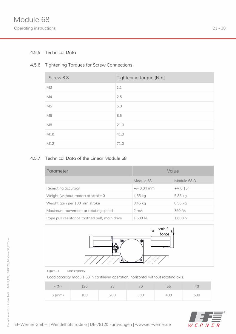
4.5.6 Tightening Torques for Screw Connections
Screw 8.8 Tightening torque [Nm]
M3 1.1
M4 2.5
M5 5.0
M6 8.5
M8 21.0
M10 41.0
M12 71.0
4.5.7 Technical Data of the Linear Module 68
Parameter Value
Module 68 Module 68 D
Repeating accuracy +/- 0.04 mm
+/- 0.15°
Weight (without motor) at stroke 0 4.55 kg 5.85 kg
Weight gain per 100 mm stroke 0.45 kg 0.55 kg
Maximum movement or rotating speed 2 m/s 360 °/s
Rope pull resistance toothed belt, main drive 1,680 N 1,680 N
Figure 11 Load capacity
Load capacity module 68 in cantilever operation, horizontal without rotating axis.
F (N) 120 85 70 55 40
S (mm) 100 200 300 400 500
Module 68 22 - 38 Operating instructions
IEF-Werner GmbH | Wendelhofstraße 6 | DE-78120 Furtwangen | www.ief-werner.de
Erst
ellt
von:
Fra
nk R
eich
elt
| M
AN
_EN
_104
0579
_Mod
ule
68_R
2f.d
oc
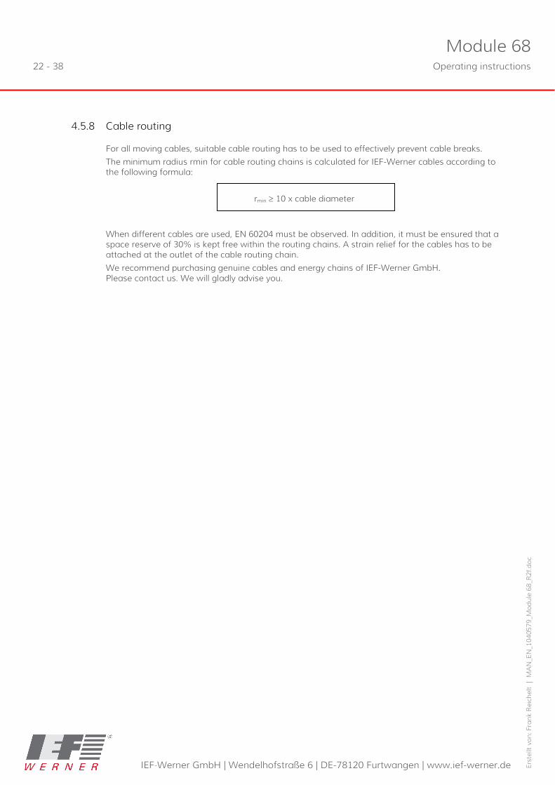
4.5.8 Cable routing
For all moving cables, suitable cable routing has to be used to effectively prevent cable breaks.
The minimum radius rmin for cable routing chains is calculated for IEF-Werner cables according to the following formula:
rmin ≥ 10 x cable diameter
When different cables are used, EN 60204 must be observed. In addition, it must be ensured that a space reserve of 30% is kept free within the routing chains. A strain relief for the cables has to be attached at the outlet of the cable routing chain.
We recommend purchasing genuine cables and energy chains of IEF-Werner GmbH. Please contact us. We will gladly advise you.

Module 68 Operating instructions 23 - 38
IEF-Werner GmbH | Wendelhofstraße 6 | DE-78120 Furtwangen | www.ief-werner.de
Erst
ellt
von:
Fra
nk R
eich
elt
| M
AN
_EN
_104
0579
_Mod
ule
68_R
2f.d
oc
4.5.9 Type plate
The type label of the Module 68 is attached on following position:
Figure 12 Position of type plate
A Type plate Module 68
Figure 13 Type plate
A Part number B Serial number
C Type designation D Feed/motor revolution

Module 68 24 - 38 Operating instructions
IEF-Werner GmbH | Wendelhofstraße 6 | DE-78120 Furtwangen | www.ief-werner.de
Erst
ellt
von:
Fra
nk R
eich
elt
| M
AN
_EN
_104
0579
_Mod
ule
68_R
2f.d
oc
4.5.10 Technical Data when using a Planetary Gear
Before commissioning, observe the possible input speeds of the gear manufacturers.
Too-high input speeds can lead to increased wear at the gear and/or thermal problems.
The precision of the linear unit is influenced by the reverse play of the gears.
Example:
The gear reverse play (S) is 9 angle minutes.
How high is the reverse play at the carriage of the linear unit?
Infeed constant of the linear unit (Vk): 140 mm
Reverse play at the carriage = (Vk • S) / (360x60)
= (140 mm • 9) / (360x60)
= 0.058 mm
Consider the information of the respective gear manufacturer in any case.
e.g. http://www.neugart.de/index.php/gb/products/Standard-gearboxes/PSN
http://alpha.wittenstein.de/
Module 68 Operating instructions 25 - 38
IEF-Werner GmbH | Wendelhofstraße 6 | DE-78120 Furtwangen | www.ief-werner.de
Erst
ellt
von:
Fra
nk R
eich
elt
| M
AN
_EN
_104
0579
_Mod
ule
68_R
2f.d
oc
5 Maintenance and Repair
DANGER
Warning of dangerous electrical voltage.
The system must be powered down for all assembly, disassembly or repair work. Non-observance of the safety provisions may cause death.
CAUTION
Repairs by specialist personnel only.
Any repairs must only be performed by specialist personnel who have read and understood these original operating instructions.
Only use genuine spare parts, since IEF-Werner GmbH will not assume any warranty otherwise.
5.1 Lubrication of guide carriage
During the design of the linear units Module 68 and Module 68 D, great importance was placed on the use of low-maintenance components.
All roller elements were provided with lifetime lubrication in the factory.
To avoid danger of over-lubrication of the linear bearings, no external lubrication nipples were attached to the carriage part.
However, to achieve a high service life of the dirt wipers, we recommend lubricating the guide shafts with special grease at regular intervals. The lubricant may be procured from IEF in tubes of 50 gr (part no.729148) each.
The recommended maintenance intervals add up to approx. 200 operating hours under regular ambience conditions. The maintenance intervals should be reduced under difficult ambient conditions.
5.2 Tooth belt tension
The toothed belt tension for module 68 is set with spacer ring.
■ See chapter Module 68, TG1000018, Installation variant 1, 30 and
■ Module 68, TG1000018, installation variants 2 and 3, 32
5.3 Belt tension gear toothed belt
The belt tension of the gear toothed belt should be 150 N.
■ See chapter Module 68 gearbox, TG 1000032, 36, drawing item 20.

Module 68 26 - 38 Operating instructions
IEF-Werner GmbH | Wendelhofstraße 6 | DE-78120 Furtwangen | www.ief-werner.de
Erst
ellt
von:
Fra
nk R
eich
elt
| M
AN
_EN
_104
0579
_Mod
ule
68_R
2f.d
oc
5.4 Drive unit
Always observe the installation size for the drive unit. See Figure 14, below and Figure 15, 31, drawing item 100.
Figure 14 Drive unit, installation variant 1
A Drive unit B Clamping ring Tightening torque: 7.5 Nm

Module 68 Operating instructions 27 - 38
IEF-Werner GmbH | Wendelhofstraße 6 | DE-78120 Furtwangen | www.ief-werner.de
Erst
ellt
von:
Fra
nk R
eich
elt
| M
AN
_EN
_104
0579
_Mod
ule
68_R
2f.d
oc
6 Troubleshooting
Interference Reason Correction
Increased running noise
Nominal service life of guide linear bearing exceeded
Replace all linear bearings
Linear bearing worn due to overload (too-high torque, etc.)
Replace all linear bearings, reduce load
Linear bearing worn from strong contamination
Replace all linear bearings, clean guide elements, guide shafts more often if required
Guide shafts corroded Replace guide shafts, replace linear bearing if required, lubricate guide shafts more often
Guide shafts worn Replace guide shafts, replace all linear bearings, check load, protect linear module from strong contamination
Drive unit worn Replace drive unit
Toothed belt runs dry Slightly lubricate toothed belt on the toothed inner side
Toothed belt tension too high Install reconciled spacer sleeves as shaft stop
Toothed belt strongly contaminated on the toothed inner side
Replace toothed belt, protect linear module from strong contamination
Toothed belt defective Replace toothed belt
Motor (motor bearing) defective Replace motor
For motor with brake: Brake does not open
Apply current to the brake, if the brake still does not open, replace motor

Module 68 28 - 38 Operating instructions
IEF-Werner GmbH | Wendelhofstraße 6 | DE-78120 Furtwangen | www.ief-werner.de
Erst
ellt
von:
Fra
nk R
eich
elt
| M
AN
_EN
_104
0579
_Mod
ule
68_R
2f.d
oc
Interference Reason Correction
Linear drive unit does not move
Limit switch cable not connected Connect the cable
Limit switch defective Replace limit switch
Limit switch cable defective Check limit switch cable, replace cable, if required
Solder connection on socket has come loose
Solder on wires
Motor connected incorrectly Check and change connector assignment, if required
Motor defective Replace motor
Error in power electronics or control unit
Check the power electronics or the control unit
Motor cable defective Check motor cable, replace cable, if required
Play on reversal Drive toothed belt not tensioned Pull deflection unit to stop on spacer sleeves
Linear drive unit moves mechanically against the stop during the reference run
Incorrect direction of rotation Change motor direction of rotation
Broken motor cable Replace cable


Module 68 30 - 38 Operating instructions
IEF-Werner GmbH | Wendelhofstraße 6 | DE-78120 Furtwangen | www.ief-werner.de
Erst
ellt
von:
Fra
nk R
eich
elt
| M
AN
_EN
_104
0579
_Mod
ule
68_R
2f.d
oc
7 Parts lists and drawings
7.1 Module 68, TG1000018, Installation variant 1
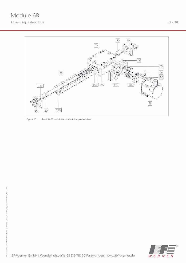
Drawing item Part-No. Designation
10 27008 End plate
20 1080057 Belt tensioner
30 TG1000023 Basic body
40 526820 Carriage complete
50 + Flange plate (depending on motor)
60 25626 Retaining plate
70 725163 Installation plug round, type: SFV 50/6
80 725164 Angled coupling, type: WKV 50/6
90 TG1000041 Motor and motor flange (depending on design)
100 + Drive unit (depending on motor)
110 732284 Plastic cover, Ø 25/20.5, type: GPN 910/766
120 1114530 Toothed belt, type: 25AT5 E-wire 0.3
130 730385 Spacer Ring, type: EVO 3 (for limitation of the belt tension)
140 726122 Inductive sensor, type: BES 516-300-S180-02
150 626705 Cylinder screw, type: ISO 4762-M x 8 – 8.8
+ use depending on design
Module 68 Operating instructions 31 - 38
IEF-Werner GmbH | Wendelhofstraße 6 | DE-78120 Furtwangen | www.ief-werner.de
Erst
ellt
von:
Fra
nk R
eich
elt
| M
AN
_EN
_104
0579
_Mod
ule
68_R
2f.d
oc
Figure 15 Module 68 installation variant 1, exploded view

Module 68 32 - 38 Operating instructions
IEF-Werner GmbH | Wendelhofstraße 6 | DE-78120 Furtwangen | www.ief-werner.de
Erst
ellt
von:
Fra
nk R
eich
elt
| M
AN
_EN
_104
0579
_Mod
ule
68_R
2f.d
oc
7.2 Module 68, TG1000018, installation variants 2 and 3
Figure 16 Module 68, installation variants 2 and 3
A Motor installation variant 2 B Motor installation variant 3
Module 68 installation variant 3
Drawing item Part-No. Designation
10 27008 End plate
20 1080057 Belt tensioner
30 TG1000023 Basic body
40 526820 Carriage complete
60 25626 Retaining plate
70 725163 Installation plug round, type: SFV 50/6
80 725164 Angled coupling, type: WKV 50/6
90 + TG1000041 Motor and motor flange (depending on design)
100 526649 Drive unit module 68V complete
120 1114530 Toothed belt, type: 25AT5 E-wire 0.3
130 730385 Spacer Ring, type: EVO 3 (for limitation of the belt tension)
140 726122 Inductive sensor, type: BES 516-300-S180-02
150 626705 Cylinder screw, type: ISO 4762-M x 8 – 8.8
160 + TG1000032 Gearbox (see Module 68 gearbox, TG 1000032, 36)
+ use depending on design

Module 68 Operating instructions 33 - 38
IEF-Werner GmbH | Wendelhofstraße 6 | DE-78120 Furtwangen | www.ief-werner.de
Erst
ellt
von:
Fra
nk R
eich
elt
| M
AN
_EN
_104
0579
_Mod
ule
68_R
2f.d
oc
Figure 17 Module 68, installation variant 3, exploded view

Module 68 34 - 38 Operating instructions
IEF-Werner GmbH | Wendelhofstraße 6 | DE-78120 Furtwangen | www.ief-werner.de
Erst
ellt
von:
Fra
nk R
eich
elt
| M
AN
_EN
_104
0579
_Mod
ule
68_R
2f.d
oc
7.3 Carriage Module 68, Part no. 526820
Drawing item Part-No. Designation
10 25639 Carriage plate
20 25631 Shaft
30 525181 Clamping block complete, type: module 105
..10 30332 Clamping block
See Figure 21, 38
..20 1000466 Linear bearing
..30 26481 Damper
..40 100492 Fixing screw
40 525796 Clamping block complete, type: module 68
..10 27664 Clamping block with milling cut out See Figure 20, 38
..20 1000466 Linear bearing
..30 26481 Damper
..40 100492 Fixing screw
50 25625 Guide roller
60 625144 Needle roller bearings
80 1010367 Sealing plug Ø 13.7 mm nature, type: GPN300 V 10

Module 68 Operating instructions 35 - 38
IEF-Werner GmbH | Wendelhofstraße 6 | DE-78120 Furtwangen | www.ief-werner.de
Erst
ellt
von:
Fra
nk R
eich
elt
| M
AN
_EN
_104
0579
_Mod
ule
68_R
2f.d
oc
Figure 18 Carriage module 68, exploded view

Module 68 36 - 38 Operating instructions
IEF-Werner GmbH | Wendelhofstraße 6 | DE-78120 Furtwangen | www.ief-werner.de
Erst
ellt
von:
Fra
nk R
eich
elt
| M
AN
_EN
_104
0579
_Mod
ule
68_R
2f.d
oc
7.4 Module 68 gearbox, TG 1000032
Drawing item Part-No. Designation
10 526645 Motor flange assembly
20 + Gear toothed belt
30 + Driven toothed disc
40 527263 Clamping set, type: 15/28
50 + Motor toothed disc
+ use depending on design
Additionally, please observe the wear parts lists included with the delivery according to the order.

Module 68 Operating instructions 37 - 38
IEF-Werner GmbH | Wendelhofstraße 6 | DE-78120 Furtwangen | www.ief-werner.de
Erst
ellt
von:
Fra
nk R
eich
elt
| M
AN
_EN
_104
0579
_Mod
ule
68_R
2f.d
oc
Figure 19 Belt drive module 68, exploded view

Module 68 38 - 38 Operating instructions
IEF-Werner GmbH | Wendelhofstraße 6 | DE-78120 Furtwangen | www.ief-werner.de
Erst
ellt
von:
Fra
nk R
eich
elt
| M
AN
_EN
_104
0579
_Mod
ule
68_R
2f.d
oc
7.5 Clamping block complete, Part No. 525796
Figure 20 Clamping block module 68, exploded view (see Carriage Module 68, Part no. 526820, 34, drawing item. 40)
7.6 Clamping block complete, Part No. 525181
Figure 21 Clamping block module 105, exploded view (see Carriage Module 68, Part no. 526820, 34, Drawing item 30)