Product manual ABB i-bus KNX · Product manual ABB i-bus® KNX DALI-Gateway DG/S 8.1 Intelligent...
75
Product manual ABB i-bus ® KNX DALI-Gateway DG/S 8.1 Intelligent Installation Systems
-
Upload
truongkhanh -
Category
Documents
-
view
255 -
download
4
Transcript of Product manual ABB i-bus KNX · Product manual ABB i-bus® KNX DALI-Gateway DG/S 8.1 Intelligent...

Product manual ABB i-bus® KNX
DALI-Gateway
DG/S 8.1
Intelligent Installation Systems

This manual describes the function of the DALI-Gateway DG/S 8.1 with the application program “Dim Slave Lightscenes Dynamic 8f/1.1”.
Subject to changes and errors excepted.
Limitation of liability:
Despite checking that the contents of this document match the hardware and software, deviations cannot be completely excluded. We therefore cannot accept any liability for this. Any necessary corrections will be inserted in new versions of the manual.Please inform us of any suggested improvements.E-mail: [email protected]
Contents
1
Page
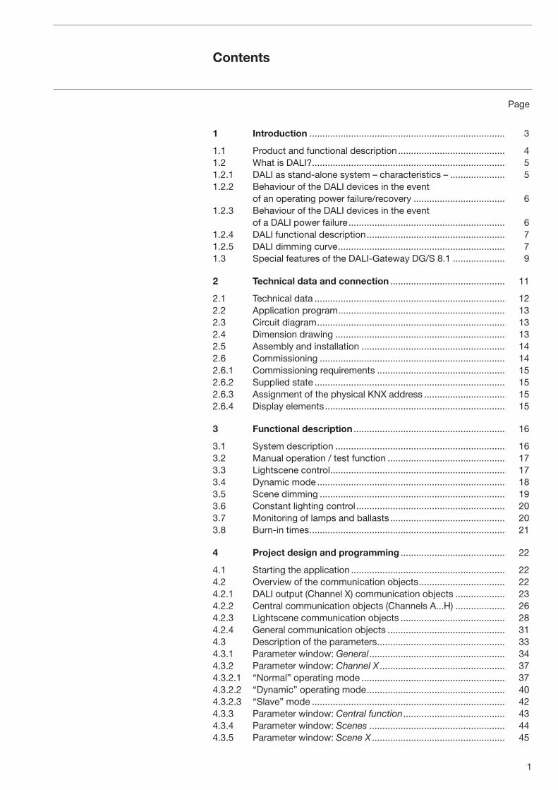
1 Introduction ........................................................................... 3
1.1 Product and functional description ......................................... 41.2 What is DALI? .......................................................................... 51.2.1 DALI as stand-alone system – characteristics – ..................... 51.2.2 Behaviour of the DALI devices in the event
of an operating power failure/recovery ................................... 61.2.3 Behaviour of the DALI devices in the event
of a DALI power failure ............................................................ 61.2.4 DALI functional description ..................................................... 71.2.5 DALI dimming curve ................................................................ 71.3 Special features of the DALI-Gateway DG/S 8.1 .................... 9
2 Technical data and connection ............................................ 11
2.1 Technical data ......................................................................... 122.2 Application program ................................................................ 132.3 Circuit diagram ........................................................................ 132.4 Dimension drawing ................................................................. 132.5 Assembly and installation ....................................................... 142.6 Commissioning ....................................................................... 142.6.1 Commissioning requirements ................................................. 152.6.2 Supplied state ......................................................................... 152.6.3 Assignment of the physical KNX address ............................... 152.6.4 Display elements ..................................................................... 15
3 Functional description .......................................................... 16
3.1 System description ................................................................. 163.2 Manual operation / test function ............................................. 173.3 Lightscene control ................................................................... 173.4 Dynamic mode ........................................................................ 183.5 Scene dimming ....................................................................... 193.6 Constant lighting control ......................................................... 203.7 Monitoring of lamps and ballasts ............................................ 203.8 Burn-in times ........................................................................... 21
4 Project design and programming ........................................ 22
4.1 Starting the application ........................................................... 224.2 Overview of the communication objects ................................. 224.2.1 DALI output (Channel X) communication objects ................... 234.2.2 Central communication objects (Channels A...H) ................... 264.2.3 Lightscene communication objects ........................................ 284.2.4 General communication objects ............................................. 314.3 Description of the parameters ................................................. 334.3.1 Parameter window: General .................................................... 344.3.2 Parameter window: Channel X ................................................ 374.3.2.1 “Normal” operating mode ....................................................... 374.3.2.2 “Dynamic” operating mode ..................................................... 404.3.2.3 “Slave” mode .......................................................................... 424.3.3 Parameter window: Central function ....................................... 434.3.4 Parameter window: Scenes .................................................... 444.3.5 Parameter window: Scene X ................................................... 45

2
Contents
Page
4.3.6 Parameter window: Status ...................................................... 474.4 Behaviour in the event of malfunctions ................................... 504.4.1 Behaviour on voltage failure .................................................... 514.4.2 Behaviour on voltage recovery ................................................ 53
5 Application and planning ...................................................... 55
5.1 8-bit-scene .............................................................................. 555.2 Coloured light with LED technology and DALI ........................ 565.3 Staircase lighting function ....................................................... 575.4 Facility Management ............................................................... 585.5 Assignment of the switch sensor ............................................ 59
6 Maintenance .......................................................................... 61
6.1 DALI-Gateway DG/S 8.1 ......................................................... 616.2 DALI devices ........................................................................... 61
Appendix ................................................................................ 62
A.1 Overview DALI devices ........................................................... 62A.2 Key table for 8-bit scene telegram .......................................... 63A.3 Conversion of older application program ................................ 64A.4 Definition of terms ................................................................... 65A.5 List of diagrams ....................................................................... 68A.6 List of tables ............................................................................ 68A.7 Further information about DALI ............................................... 69A.8 Specification text .................................................................... 70A.9 Ordering information ............................................................... 71A.9.1 Scope of supply ...................................................................... 71
Seite überarbeitet,
bitte überprüfen, danke!

3
ABB i-bus® KNX Introduction
1 Introduction The ABB i-bus® DALI-Gateway DG/S 8.1 is the link between DALI equipment and the KNX. 8 DALI outputs (channels) can be connected to the DALI-Gateway DG/S 8.1 with a maximum of 16 per channel. Up to 128 devices with a DALI interface can be connected to the DALI Gateway. No further DALI system devices are required such as a DALI power source, controller, function module or switch. In addition, no addressing or commissioning of the DALI devices needs to be carried out.
The functions of switching, dimming, setting brightness values, lamp and ballast error signals are available for each output. A lamp burn-in time and 16 lightscenes can be set. A slave operation – in order to integrate the individual channels in a constant light control – rounds off the functions.
The manual gives detailed information about the installation, programming and parameterisation of the device and explains the use of the DG/S 8.1 by way of examples.
When reading the manual, you obtain the necessary knowledge to integrate the DALI-Gateway DG/S 8.1 into an KNX building system. An attempt has also been made to make the manual as understandable and complete for those who have not previously had much experience with DALI.
To be familiar with the Engineering Tool Software ETS is a prerequisite.
ABB STOTZ KONTAKT GmbH retains the legal right to the copyright of this manual.
Fig. 1: DALI-Gateway DG/S 8.1
2CD
C 0
71 0
52 F
0005

4
ABB i-bus® KNX
1.1 Product and
functional description
Introduction
The ABB i-bus® DALI-Gateway DG/S 8.1 is a DIN rail mounted device with a width of 6 modules in the proM design for insertion in the distribution board. The connection to the ABB i-bus® is established via a bus connection terminal at the front of the device. The DALI Gateway requires an AC or DC auxiliary supply. The assignment of the physical address, as well as the pa-rameter settings is carried out via the Engineering Tool Software ETS (from version ETS2 V1.3 onwards) with a VD2 file. For programming the device with ETS3, the relevant VD3 file must be applied.
The following functions can be controlled via the KNX with the DALI-Gate-way DG/S 8.1 in conjunction with devices that have a DALI interface:
Brightness values, can be switched on, switched off or set per channel.
Individual lighting control, with adjustable dimming speeds and transition times is possible.
16 lightscenes, are assembled together with the 8 DALI outputs (channels). The scene brightness values can be set, stored and retrieved via the ETS or the communication object. It is possible to recall or store a scene over 1Bit or 1Byte Object.
In dynamic mode, a staircase lighting function or a timed brightness progression can be assigned to each channel. It is possible to set starting values, hold values and switch OFF values as well as the corresponding changeover points individually per channel.
In slave mode, each channel can be priority controlled via a 1-byte input signal. In connection with corresponding KNX devices, constant lighting control or repeated lighting processes can be controlled.
Lamp and ballast faults are detected and reported. The status of a lighting system can thus be continually monitored and the appropriate information can be routed. Since the device can also function in DC mode, there is no obstacle to emergency power applications.
The DALI Gateway continually issues the current status of its own operability as well as the connected DALI devices via status signals.
Two LEDs on the gateway provide direct information about the status of the device. They report whether the gateway is functioning correctly and display errors in the DALI outputs (channels).
To enable the DALI Gateway to function correctly, it must be ensured that the connected DALI equipment is in accordance with DIN EN 60929 and IEC 62386 respectively and thus conforms to the DALI standard.

5
ABB i-bus® KNX Introduction
1.2 What is DALI?
1.2.1 DALI as stand-alone
system – characteristics –
The requirements for modern lighting technology are extremely varied. While previously lighting was only required for visual tasks, nowadays factors such as comfort, ambience, functionality and energy saving are in the foreground. Furthermore, a modern lighting system is increasingly being incorporated in the Facility Management (maintenance and preparation management) of the building installation. Often, a complex lighting manage-ment system is needed which meets the uses of the premises. All these requirements are either not adequately met by the traditional analogue electrical installation or only with considerable effort and cost. The DALI standard has emerged from this background.
The manufacturers from the lighting industry, primarily the leading manufacturers of electronic ballasts, joined together to define a new standard for the digital communication of a lighting system. This resulted in the DALI protocol (Digital Addressable Lighting Interface).
The DALI standard enables addressing of up to
• 64 devices with a DALI interface
and compiling these devices into
• 16 lightscenes (incl. dimming values and transitional periods) and
• 16 lighting groups (multiple assignments of the devices are possible).
Fig. 2: DALI block diagram
A two-core control cable which does not need to be shielded is used for the exchange of information and transmission of the digital commands. It is not necessary to take the polarity into account. The control cable must not have any SELV characteristics (safety extra-low voltage). The two unrequired cores of the five-core NYM 5x1.5 mm2 mains cable can thus be used for example as a DALI cable.
64
63
or
1 3
2 4
Ballast
BallastBallastRelay
DimmerBallastControllerScene module
Control device
Power source

6
ABB i-bus® KNX Introduction
A DALI power source (16 V DC) supplies the individual DALI devices, the DALI processor, controller, control devices or modules which are responsible for managing the scenes and groups in the DALI line.
A separate relay or a calculation of the switching capacity is not required as the switching relay is integrated in the DALI ballast.
There are DALI devices (e.g. LED DALI converter, DALI switch actuators) which consist internally of several DALI devices and can only be addressed via a common DALI control cable. The internal DALI devices have different individual DALI addresses and can be addressed individually via DALI.
These devices can be connected to the DALI-Gateway DG/S 8.1. The internal DALI devices are detected and monitored. They cannot however be triggered individually. The control is carried out globally.
The following behaviour is defined in the supplied state of the DALI devices: when the operating voltage of the DALI devices is interrupted, the connec-ted luminaire fails. On mains voltage recovery, the luminaire is switched on again with 100% brightness. The electrical installer can thus switch the DALI lighting on and off e.g. with an automatic circuit-breaker, even if the individual DALI devices have not yet been addressed.
This behaviour of the connected DALI equipment on failure and recovery of the operating voltage can be parameterised with the DALI Gateway. See chapter “Voltage failure” or “Voltage recovery”.
If the operating voltage of a DALI device (e.g. electronic ballast) fails, the device is no longer able to work. The light goes out since the luminary is no longer supplied with operating voltage.
In the delivery status, the operating units with a DALI interface usually set the luminaries to maximal brightness (100%) when the operating voltage is applied for the first time or when it is restored. This “Power UP Level” is pre-defined by the manufacturer of the electronic ballast. As a result, the electri-cian can switch the DALI illumination on or off, e.g. with an automatic circuit breaker, even if the individual DALI devices have not been addressed yet.
The 8-fold KNX DALI gateway, DG/S 8.1, interprets a failure of the operat-ing voltage of the DALI devices as a fault of the electronic ballast, since the DALI device does not reply anymore. Once the operating voltage is restored, the electronic ballast is switched on with maximal brightness (100%) as it is requested by the manufacturer. After 1 or 2 seconds, the “recovered” elec-tronic ballast(s) will be set to the brightness that is currently set for the corre-sponding channel. They are controlled cyclically by the 8-fold DALI gateway. An explicit parameterisation in the DALI gateway is not provided.
In the delivery status, the operating units with a DALI interface usually switch over to the emergency mode and activate the connected luminaries with maximal brightness in the event of a DALI power failure (e.g. due to a rupture, a short-circuit of the control line or a defective DALI power source). This value can be parameterised by the DALI gateway DG/S 8.1.
1.2.2 Behaviour of the DALI
devices in the event
of an operating power
failure/recovery
1.2.3 Behaviour of the DALI
devices in the event
of a DALI power failure

7
ABB i-bus® KNX
The DALI interface norm is standardised in DIN IEC 60929. With DALI, a standard has been created which meets the requirements of modern lighting technology due to its digital possibilities. The essential functions are:
• Individual dimming speeds for each device
• Lightscenes with fade times
• Scene devices reach their final brightness value simultaneously
• DALI ballasts have a dimming range of 1 to 100%
• DALI uses a logarithmic dimming curve
• Current brightness values and ON/OFF states can be queried
• Ballast and lamp faults are detected
• Behaviour in the event of a system fault can be defined
• Global control of all DALI devices (broadcast mode)
DALI has established itself since 1999 as a company-neutral interface standard. It is possible to control fluorescent lamps, incandescent lamps, LEDs etc. via DALI, combine them into light scenes and to integrate them with the ABB i-bus® DALI-Gateway DG/S 8.1 in the KNX building installation.
The DALI standard can be seen as a subsystem of modern building system technology which links the components of lighting technology and is not dependent on one manufacturer.
The DALI dimming curve is matching the sensitivity of the human eye. Therefore results a logarithmic dimming curve, which is a linear brightness response for the human.
The dimming value is shown in the following diagram. The curve is specified in the DALI standard (EN 60929 or IEC 62386).
As not all DALI control gear start at 0.1 % luminous flux, the minimal physi-cal dimming level is to attend. E.g. 126 (corresponding to 3 %) is the lowest value for DALI ECGs with a minimal dimming level of 3 %. All values (except
Introduction
1.2.4 DALI functional description
1.2.5 DALI dimming curve

8
for 0 = off) below 126 (50% brightness, 3% luminous flux) are interpreted as the minimal lighting level.
Together with the DALI Gateway following effect is to attend: For example on the ECG is a dimming zone from 3…100% printed, you have an ECG which can not drop under the minimal luminous flux of 3%. This could re-sponse of a certain switching on of the fluorescent lamp. This minimal lumi-nous flux of 3% corresponds with a DALI dimming value of 126 Digits. This value is 50% of the percentage brightness. This means that a lower bright-ness level (under 50%) is not possible. Lower brightness values will copy on the 50% value. If a brightness value lower than 50% will set over the KNX this will copy to the same DALI brightness. But the lamp only can switch on the brightness value of 50%. This real lamp brightness will send back to the KNX and visualised.
The same behaviour will happen with a dimming command. If the minimal dimming level is reached and a dimming down command will received again, only the minimal dimming level, in our case 50%, will send back to the KNX.
To avoid such a limitation, suitable ballast with a dimming range of 1%...100% or 0.1%...100% have to be used.
ABB i-bus® KNX Introduction

9
ABB i-bus® KNX Introduction
With the DALI-Gateway DG/S 8.1, it is possible to utilise the benefits of the DALI standard in the KNX building system technology. There is no time-consuming addressing of the individual DALI devices necessary. Up to 128 DALI devices can be connected to the DALI Gateway.
A maximum of 16 DALI devices can be connected to the DALI-Gateway DG/S 8.1 per DALI output (channel), with a total of 128 DALI devices on the entire gateway. As no individual addressing of the DALI devices is carried out, the 16 devices per channel can only be controlled and monitored together as a group. A ballast and lamp fault can be detected per channel and reported. It is not apparent which channel device has caused the error message.
These factors predetermine the DALI Gateway for the control of lighting strips in offices, factories or warehouses or several lamps in one room.
The omission of a time-consuming addressing process is particularly noticeable in offices which lead off corridors, hotel rooms or patient rooms in hospitals or old people’s homes in which the individual luminaires are not visible. Addressing, which requires visual contact with the luminaire, would only be possible in this case with considerable effort.
For the DALI-Gateway DG/S 8.1, the installation and grouping of the DALI devices is carried out via the wiring in the same way as the 1...10 V tech-nology. The electrical installer does not need to change his installation practices and can still utilise the benefits of DALI digital lighting control.The combination of the DALI devices in groups of luminaires via software is carried out directly with KNX group assignment.
Individual control and monitoring is possible for 8 devices with a DALI-Gate-way DG/S 8.1 if only one device is connected per channel. A very detailed lighting control system can therefore be used, for example in a lecture room or exhibition area.
The DALI-Gateway DG/S 8.1 does not require a DALI power supply, DALI controller or other DALI function module. The DALI Gateway takes over these tasks together with the KNX grouping in ETS.
As DALI is a master/slave system, the DALI Gateway (master) cannot work together with other DALI masters. In this case, function and telegram collisions may occur.
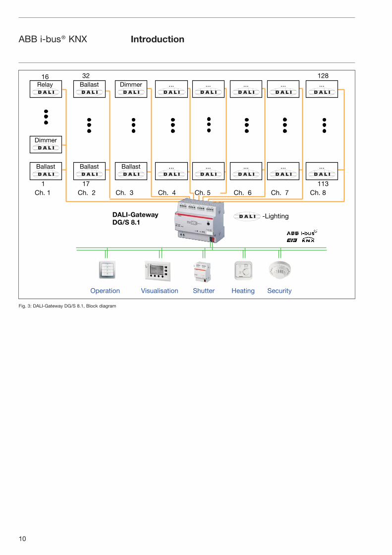
The following diagram explains the channel-related functioning of the DALI-Gateway DG/S 8.1.
1.3 Special features of the
DALI-Gateway DG/S 8.1
10
ABB i-bus® KNX
Fig. 3: DALI-Gateway DG/S 8.1, Block diagram
Introduction
Shutter Heating Security
-Lighting
1
16 32 128
11317
Relay Ballast
Ballast
Dimmer
Ballast Ballast
Dimmer
... ... ... ... ...
... ... ... ... ...
Ch. 1 Ch. 2 Ch. 3 Ch. 4 Ch. 5 Ch. 6 Ch. 7 Ch. 8
DALI-Gateway
DG/S 8.1
Operation Visualisation

11
ABB i-bus® KNX
2 Technical data and connection
Technical data and connection
The device-specific functions are explained more detail in the following sections.
The DALI Gateway is a DIN rail mounted device for insertion in the distribu-tion board. It is used for controlling DALI equipment e.g. ballasts, transfor-mers, relays etc. via the KNX.
Up to 128 DALI devices (max. 16 per output) can be connected to 8 inde-pendent DALI outputs (channels).
The DALI Gateway has a test button which enables the DALI outputs to be manually switched in sequence in a test mode without bus voltage connec-ted.
The DALI-Gateway DG/S 8.1 has an AC or DC mains supply. The connection to the ABB i-bus® in the device is established via the bus connection terminal.
The DALI Gateway is parameterised with the application program Dim Slave Lightscenes Dynamic 8f/1.1 and the ETS software.
12
ABB i-bus® KNX Technical data and connection
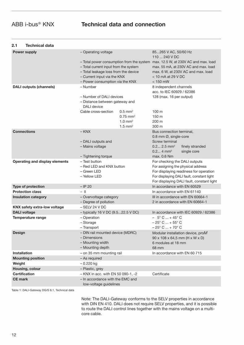
2.1 Technical data
Table 1: DALI-Gateway DG/S 8.1, Technical data
Note: The DALI-Gateway conforms to the SELV properties in accordance with DIN EN 410. DALI does not require SELV properties, and it is possible to route the DALI control lines together with the mains voltage on a multi-core cable.
Power supply – Operating voltage
– Total power consumption from the system– Total current input from the system– Total leakage loss from the device– Current input via the KNX– Power consumption via the KNX
85...265 V AC, 50/60 Hz110 ... 240 V DCmax. 12.5 W, at 230V AC and max. loadmax. 55 mA, at 230V AC and max. loadmax. 6 W, at 230V AC and max. load< 10 mA at 29 V DC< 150 mW
DALI outputs (channels) – Number
– Number of DALI devices– Distance between gateway and
DALI deviceCable cross-section 0.5 mm2
0.75 mm2
1.0 mm2
1.5 mm2
8 independent channels acc. to IEC 60929 / 62386128 (max. 16 per output)
100 m150 m200 m300 m
Connections – KNX
– DALI outputs and– Mains voltage
– Tightening torque
Bus connection terminal,0.8 mm Ø, single-coreScrew terminal 0.2... 2.5 mm2 finely stranded0.2... 4 mm2 single coremax. 0.6 Nm
Operating and display elements – Test button– Red LED and KNX button– Green LED– Yellow LED
For checking the DALI outputsFor assigning the physical addressFor displaying readiness for operationFor displaying DALI fault, constant lightFor displaying DALI fault, constant light
Type of protection – IP 20 In accordance with EN 60529Protection class – II In accordance with EN 61140Insulation category – Overvoltage category
– Degree of pollutionIII in accordance with EN 60664-12 in accordance with EN 60664-1
KNX safety extra-low voltage – SELV 24 V DCDALI voltage – typically 16 V DC (9.5...22.5 V DC) In accordance with IEC 60929 / 62386Temperature range – Operation
– Storage– Transport
– 5° C ... + 45° C– 25° C ... + 55° C– 25° C ... + 70° C
Design – DIN rail mounted device (MDRC)– Dimensions– Mounting width– Mounting depth
Modular installation device, proM90 x 108 x 64,5 mm (H x W x D)6 modules at 18 mm68 mm
Installation – on 35 mm mounting rail In accordance with EN 60 715Mounting position – As requiredWeight – 0.220 kgHousing, colour – Plastic, greyCertification – KNX in acc. with EN 50 090-1, -2 CertificateCE mark – In accordance with the EMC and
low-voltage guidelines
13
ABB i-bus® KNX
Note: ETS2 V1.3 or higher is required for programming. When using ETS3, a file of type “VD3” must be imported. The application program is stored in ETS2/ETS3 under ABB/Illumination/DALI/Dim Slave Lightscenes Dynamic 8f/1.1.
2.2 Application program
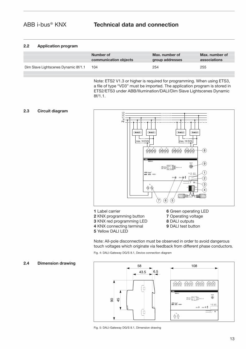
2.3 Circuit diagram
2.4 Dimension drawing
Technical data and connection
Number of Max. number of Max. number of
communication objects group addresses associations
Dim Slave Lightscenes Dynamic 8f/1.1 104 254 255
1 Label carrier 6 Green operating LED2 KNX programming button 7 Operating voltage3 KNX red programming LED 8 DALI outputs4 KNX connecting terminal 9 DALI test button5 Yellow DALI LED
Note: All-pole disconnection must be observed in order to avoid dangerous touch voltages which originate via feedback from different phase conductors.
Fig. 4: DALI-Gateway DG/S 8.1, Device connection diagram
Fig. 5: DALI-Gateway DG/S 8.1, Dimension drawing
���������
�
���
��
�
���������
�
����
���
������
����
�������������
�������
��������
�� �
��
��� ��� ��� ���
�� � �
��
��� ��� ��� ���
�� �� ��
!
��� ��� ��� ���
��� �� ��
"�
��� ��� ��� ���
#$#
����������������
����%�&'�
���(�)�*
�� ������� �
!
�
�
�
�
�� �
�
��
��
� �� ���
!�
���
�
����
���
������
����
�������������
�������
���������
� � ���
��� ��� ��� ���
� � � ���
��� ��� ��� ���
�� �� �� !
��� ��� ��� ���
��� �� ��"�
��� ��� ��� ���
#$#
����%�&'�
���(�)�*
������������������ ������� �

14
ABB i-bus® KNX Technical data and connection
2.5 Assembly and installation
2.6 Commissioning
The DALI-Gateway DG/S 8.1 is suitable for insertion in distribution boards or miniature housing for snapping onto 35 mm mounting rails, in accordance with EN 60 715.
The accessibility of the device for operation, testing, inspection, maintenance and repair must be ensured.
The electrical connection is carried out via screw terminals. Connection to the KNX is established with a bus connection terminal. The terminal designations are located on the housing.
Up to 16 devices with DALI interface can be connected per DALI output (channel). To do so, it is necessary to use a control cable with a maximum length (see Table 2) which is dependent on the cable cross-section.
Cable length [mm2] 2 x 0.5 2 x 0.75 2 x 1.0 2 x 1.5
Max. cable length [m] from the gateway to the DALI device
100 150 200 300
Table 2: Maximum cable length per DALI output (channel)
The figures in the table are rounded figures. The exact figures are calculated with the following form: L = A / (I x 0.018) L = Cable length in m A = Cable cross-section in mm2
I = Maximum supply current in A (0,25A)
It is possible to assemble the DALI control cable with conventional installation material for mains cables. The two cores of the five-core NYM 5x1.5 mm2 which are not required can be used without consideration of the polarity. It is not necessary to lay a separate control cable.
The assignment of the physical address as well as the parameter settings are carried out with the Engineering Tool Software ETS (from version ETS2 V1.3 onwards).
The DALI-Gateway DG/S 8.1 is ready for operation once the operating voltage has been applied. The green operating LED on the front of the de-vice lights up.
No commissioning or addressing is required for the DALI equipment. The power supply of the DALI control cable is carried out via the gateway. A separate DALI power supply is not required.
Once the operating voltage is applied, the DALI Gateway automatically detects the connected DALI equipment and is ready for operation.
No knowledge of DALI is required for commissioning the DALI Gateway. The DALI devices are connected to the gateway in the same way as 1...10 Vlighting technology. No DALI addressing or commissioning needs to be carried out. The DALI devices can be integrated directly in the KNX building technology with the appropriate communication objects once they have been installed correctly and connected to the gateway.

15
ABB i-bus® KNX Technical data and connection
The parameterisation of the gateway and the DALI equipment is carried out with the application software “Dim Slave Lightscenes Dynamic 8f/1.1” and the ETS software (from version ETS2V1.3 onwards). When using ETS3, a file of type “.VD3” must be imported. The following tasks must be carried out:
– Assignment of the physical KNX device addresses of the DALI Gateway
– Parameterisation of the lighting behaviour of the DALI devices (e.g. dimming speed, starting value, transitional period etc.)
– Definition and setting of lightscenes
– Parameterisation of the KNX control (e.g. setting flags and defining telegram transmission times)
– Parameterisation of the status functions and behaviour in the event of a fault
– Assignment of the communication objects to KNX groups
The installation and commissioning may only be carried out by specialist electricians. When planning and installing electrical installations, the appropriate norms, guidelines, regulations and specifications must be reserved.
To be able to commission the DALI-Gateway DG/S 8.1, it must be connected to an AC or DC 230 V power supply. You require a PC or laptop with ETS (from ETS2 V1.3 onwards) and an interface to the ABB i-bus® e.g. via RS232 or USB interface.
The DALI-Gateway DG/S 8.1 is supplied with the physical address 15.15.255. The connecting terminals are open and the bus connection terminal is premounted.
The assignment of the physical KNX address of the DALI-Gateway DG/S 8.1 is carried out via the ETS and the programming button on the device.
The DALI-Gateway DG/S 8.1 has a programming button for assigning the KNX physical address which is located on the shoulder of the device. Once the button has been pressed, the red programming LED lights up. It is extin-guished as soon as the ETS program has assigned the physical address or the programming button has been pressed again.
Green-LED lights up,
When power is available and the device is ready for operation
Yellow-LED lights
Up: in normal operation,Blinks: if DALI fault in Test Operation, if Gateway in Test Operation
Red LED lights up,
If the device is in the programming mode (after the programming key has been pressed).
2.6.1 Commissioning
requirements
2.6.2 Supplied state
2.6.3 Assignment of the physical
KNX address
2.6.4 Display elements
16
ABB i-bus® KNX Functional description
The essential functions and operation of the DALI-Gateway DG/S 8.1 are explained in this section.
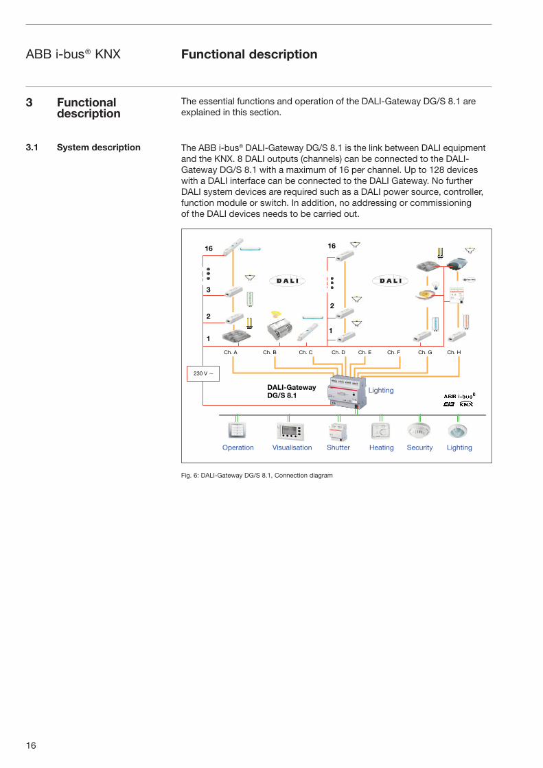
The ABB i-bus® DALI-Gateway DG/S 8.1 is the link between DALI equipment and the KNX. 8 DALI outputs (channels) can be connected to the DALI-Gateway DG/S 8.1 with a maximum of 16 per channel. Up to 128 devices with a DALI interface can be connected to the DALI Gateway. No further DALI system devices are required such as a DALI power source, controller, function module or switch. In addition, no addressing or commissioning of the DALI devices needs to be carried out.
Fig. 6: DALI-Gateway DG/S 8.1, Connection diagram
3 Functional description
3.1 System description
Lighting
230 V �
Shutter Heating Security Lighting
1
2
3
16
1
2
16
DALI-Gateway
DG/S 8.1
Ch. A Ch. B Ch. C Ch. D Ch. E Ch. F Ch. G Ch. H
Operation Visualisation

17
ABB i-bus® KNX Functional description
The DALI Gateway is fitted with a test button. If the device is connected to the mains voltage, each DALI output can be switched on manually in sequence and then off again.
Once the DALI devices are connected, they can be checked through a manual test together with the wiring without bus voltage connected.
By pressing the test button (> 2 sec.), the green operating LED is extin-guished and the test mode starts once the test button has been released. Channel A is switched on first - all the other channels are switched off. By pressing the button again (< 2 sec.), the next channel is switched on and so on. The active channel is indicated by the yellow DALI LED (1 Hz) which flashes. If you press the test button > 2 sec., the green operating LED starts to light up and the test mode ends when the test button is released.
The device automatically exits the test mode after 5 minutes if no push button action is carried out. Once test mode has ended, the channels automatically revert to the state that existed prior to testing.
Any active scene control, automatic dimming processes as well as timed processes in dynamic mode continue to run in the background but are not switched through to the channels during test mode. The channels are enabled again after exiting the test mode.
Up to 16 lightscenes can be set, stored and retrieved with the DALI-Gate-way DG/S 8.1. The lightscenes can be set and stored via the ETS or manually via push button. To prevent the manually adjusted lightscene being overwritten, each lightscene can be disabled from being overwritten in the event of an application download.
The lightscenes are composed of the 8 DALI outputs (channels). An indivi-dual brightness value can be assigned to each channel in a lightscene or be excluded from the lightscene by the parameter selection “unchanged”.
Through setting a scene transitional period, the time can be set individually per lightscene, after which all the devices in the scene have reached their lightscene brightness value.
If a scene is dimmed up or down by the central command*), the relative brightness variations of the individual channels are also stored once the maximum or minimum brightness values are stored. That means that the relative brightness values of the lightscene are stored when dimming up or down.
* Caution: The central command influences all the DALI channels of the DALI Gateway, not just the channels which are compiled in a lightscene.
3.2 Manual operation /
test function
3.3 Lightscene control
18
ABB i-bus® KNX Functional description
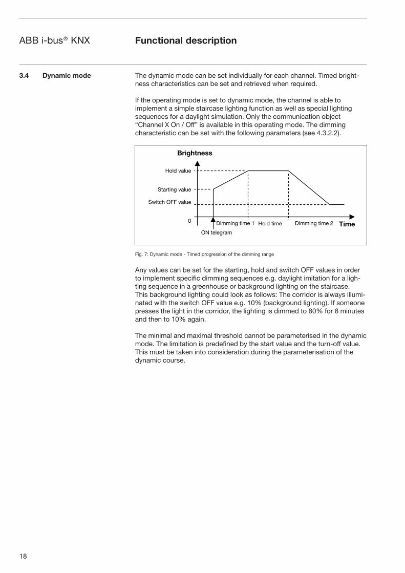
The dynamic mode can be set individually for each channel. Timed bright-ness characteristics can be set and retrieved when required.
If the operating mode is set to dynamic mode, the channel is able to implement a simple staircase lighting function as well as special lighting sequences for a daylight simulation. Only the communication object “Channel X On / Off” is available in this operating mode. The dimming characteristic can be set with the following parameters (see 4.3.2.2).
Fig. 7: Dynamic mode - Timed progression of the dimming range
Any values can be set for the starting, hold and switch OFF values in order to implement specific dimming sequences e.g. daylight imitation for a ligh-ting sequence in a greenhouse or background lighting on the staircase. This background lighting could look as follows: The corridor is always illumi-nated with the switch OFF value e.g. 10% (background lighting). If someone presses the light in the corridor, the lighting is dimmed to 80% for 8 minutes and then to 10% again.
The minimal and maximal threshold cannot be parameterised in the dynamic mode. The limitation is predefined by the start value and the turn-off value. This must be taken into consideration during the parameterisation of the dynamic course.
3.4 Dynamic mode
Brightness
Time
Hold value
Starting value
Switch OFF value
0 Dimming time 1 Dimming time 2Hold time
ON telegram

19
ABB i-bus® KNX Functional description
Scene dimming is possible with the DALI-Gateway DG/S 8.1 and the central command “Relative dimming” are described as follows:
The set brightness values and the relative brightness differences of the indi-vidual channels are maintained during the central dimming process (object relative dimming, channels A…H). This information is also maintained when the maximal or minimal brightness value is reached and when all of the luminaries have reached the maximal or minimal dimming value. When the minimal or maximal brightness values are dimmed up or down, the original brightness conditions are restored.
The following illustrations explain the principles of scenic dimming. To make it easier to understand, the minimal and maximal dimming values of the channels were set to 0% and 100% respectively.
Fig. 8: Scene dimming with central command
In detail, scenic dimming via the central dimming object (relative dimming, channels A…H) differs slightly from relative dimming in a channel. This is necessary, since all channels are regarded as a group of luminaries. At the beginning of scenic dimming, the current brightness values of each individu-al channel are determined as the starting point for dimming. Every dimming value can be dimmed up by + 50 % or down by – 50 %. This is mapped onto the actual brightness range. This means that a brightness value of 20 % can be dimmed by + 50% (which corresponds to a range of 20 – 100 %) or by -50 % (which corresponds to a range of 0 – 20%). Depending on the dimming intervals defined in the KNX, the ranges are split up and dimmed.
With an initial brightness of 50 %, this leads exactly to the dimming behav-iour used for relative dimming in the individual channels.
If at the beginning of scenic dimming all channels (A to H) are OFF (0 % brightness) or ON (100 % brightness), the possible dimming range will be set only unilaterally. This leads to a full utilisation of the dimming range without allowing dimming into the OFF or ON direction.
3.5 Scene dimming
Dimming up
A B C D E F G HChannel
Starting point
100
80
50
10
A B C D E F G HChannel
100
80
50
10
Dimming up
A B C D E F G HChannel
100
80
50
10
Dimming downStarting point
A B C D E F G H
100
80
50
10
Dimming down
A B C D E F G H
100
80
50
10
Dimming upStarting point
A B C D E F G H
100
80
50
10
Brig
htne
ssB
right
ness
Brig
htne
ssB
right
ness
Brig
htne
ssB
right
ness
ChannelChannel Channel
20
ABB i-bus® KNX Functional description
Each DALI output (channel) of the DALI-Gateway DG/S 8.1 can be priority controlled in slave mode via a 1-byte brightness value (communication object: “Channel X - Set Brightness Value”). The “slave mode” is activated and deactivated via the 1-bit communication object “Channel X - Slave Operation On / Off”. Constant lighting control is possible with an appropriate KNX device (e.g. LR/S 2.2.1), which as master supplies a 1-byte brightness value as a control value.
The application data of the master device and the KNX bus load must be taken into account.
With DALI, it is possible to monitor the DALI devices of a channel together (in broadcast). With the DALI Gateway, it is possible to distinguish between a lamp and a ballast fault. A fault is detected directly and displayed on the gateway by the yellow LED. The information is simultaneously made availa-ble via the KNX through a channel-related communication object and can be sent to a control unit or visualisation program for display purposes. From there, the necessary repair measures or corresponding maintenance cycles can be initiated. The current status of the lighting installation in the building is always available or can be retrieved on request. It is thus possible to inte-grate the lighting in a higher-order Facility Management system.
Equipment with a DALI interface can send a DALI telegram which displays a lamp fault. This information is queried by the DALI Gateway. The correspon-ding data sheets of the device manufacturer state whether the DALI equip-ment in use reports a lamp fault.
With the DALI-Gateway DG/S 8.1, it is possible to detect lamp faults per channel. It is not possible to detect how many or which of the max. 16 devices in the channel have a lamp fault.
Note: You can assume that in general all DALI ballasts support the reporting of a lamp fault. DALI dimmers and DALI switch actuators often do not have this characteristic.
To guarantee correct operation, the gateway must know how many ballasts must be monitored. This is carried out by activating the object “Detect Ballasts”. With this function, the DALI Gateway establishes automatical-ly how many ballasts are connected and uses this number as a reference value. If the installation should be extended or reduced, the option “Detect Ballasts” must be activated again. This process is only necessary if the number of ballasts per channel has changed and not when replacing a ballast in the same channel.
The duration of the ballast detection is dependent on the number of connec-ted DALI devices and can take approx. 1 minute with the maximum number of devices.
3.6 Constant lighting control
3.7 Monitoring of lamps
and ballasts

21
ABB i-bus® KNX Functional description
In the case of lamps filled with gas, a burn-in time is recommended as solid or fluid additives in them must be evaporated before optimum operation can be achieved and an optimum internal pressure in the lamp is enabled. This burn-in process is only necessary once before the start of the commissioning process.
Only after this burn-in time do fluorescent lamps have a stable operating value which ensures the best possible dimming behaviour and an optimum service life. An optimum pressure level is created in the fluorescent tube.
For installations with dimmable ballasts, many lamp manufacturers give the recommendation that a burn-in time of 20 – 100 hours must be observed. The recommended values are 20 hours for T8 lamps and 100 hours for T5 lamps. During the burn-in time, the lamps are only switched on at maximum capacity. Dimming is not possible.
The information about burn-in times can often not be found in the catalogue of the lamp manufacturer but in the descriptions of the electronic ballasts.
The reason for this is that the burn-in time is only relevant for dimmable installations. Stable operating values and reproducible brightness values are a prerequisite in these installations. Moreover, only poor evaporation of the solid or fluid additives is possible for dimmed lamps due to the reduced capacity so that in certain circumstances the maximum light yield is only achieved at a later date or not at all.
This can lead to the complete replacement of the lamps.
According to statements of lighting planners, if fluorescent lamps (particu-larly T5 lamps) are not burned in, they can even be damaged which causes them to fail earlier.
3.8 Burn-in times

22
ABB i-bus® KNX Project design and programming
The project design and programming of the DALI-Gateway DG/S 8.1 are described in this section.
Once the application “Dim Slave Lightscenes Dynamic 8f/1.1” has been imported in ETS, the communication objects described in this section are available, depending on the parameter setting. The channel-related objects are available immediately for each DALI output with its connected DALI devices. No addressing or commissioning of the DALI devices is required. The parameters can be modified directly and the objects can be assigned to any KNX groups.
Many communication objects are dynamic and are only visible if the corres-ponding parameters are activated in the application software. These communication objects are not visible when starting the project design of the DALI Gateway.
Fig. 9: Device view of ETS after importing the application (Channel A only)
The application program “Dim Slave Lightscenes Dynamic 8f/1.1” controls all the functions of the DALI Gateway. The programming and parameteri-sation is carried out via the Engineering Tool Software ETS2 V1.3 or higher. When using ETS3, a file of type “.VD3” must be imported.
Table 3: Number of communication objects
4 Project design and programming
4.1 Starting the application
4.2 Overview of the
communication objects
Number of Max. number of Max. number of
communication objects group addresses associations
Dim Slave Lightscenes Dynamic 8f/1.1 104 254 255

23
ABB i-bus® KNX Project design and programming
4.2.1 DALI output (Channel X)
communication objects
The general communication objects which are available for each DALI out-put are described in the following section. Many communication objects are dynamic and are only visible if the corresponding parameters are activated in the application software. These communication objects are not visible when starting the project design of the DALI Gateway. In the following description, Channel X represents a DALI output (channel) between A and H. The same communication objects are available for all other channels.
Fig. 10: Communication objects “Channel X”
No. Function Object name Data type Flags
0 On / Off Channel A 1 bit (EIS 1) DPT 1.001
C, W
Channel X On / Off [EIS 1; 1-bit switching]: The DALI devices of the channel are switched on or off via this object according to the predefined brightness values (parameter window Channel X).
Telegram value “1”: On “0”: Off
On receipt of an ON telegram, the parameter settings determine whether a predefined brightness value is set or the value that was selected before the channel was switched off. If the channel is switched on with any brightness value and receives an ON telegram “1”, the parameterised brightness value is set as the starting value.Starting values which lie above or below the maximum or minimum value are not set. The parameterised minimum or maximum value is set instead. It can be set via parameters whether to dim or jump to the brightness value.
1 Relative Dimming Channel A 4 bit (EIS 2) DPT 3.007
C, W
Channel X Relative Dimming [EIS 2; 4-bit dimming]: The relative dimming telegram for the corresponding channel is received via this object. On receipt of a starting command, the brightness is modified in the given direction and at the parameterised speed. If a stop command should be received before the end of the dimming process, the dimming process is interrupted and the achieved brightness value is retained.
Dimming values which lie above or below the predefined maximum or minimum value are not set. The parameterised maximum or minimum value is retained for further dimming.
Table 4: Communication objects “Channel X”

24
ABB i-bus® KNX
2 Set Brightness Value Channel A 8 bit (EIS 6) DPT 5.001
C, W
Channel X Set Brightness Value [EIS 6; 1-byte value]: The defined brightness value for the corresponding channel is received via this object. It can be set whether the channel jumps or dims to this value. A telegram with the value “0” switches the channel off. Brightness values which lie above or below the predefined maximum or minimum value are not set. The respec-tive maximum or minimum value is set instead. It can further be set whether a ballast which is switched off immediately adopts a received brightness value and then switches on or only after an ON command.
Telegram value “0”: Off “1”: Background brightness “255” = 100%
3 Slave Operation On / Off Channel A 1 bit (EIS 1) DPT 1.010
C, R, W, U
Channel X Slave Operation On / Off [EIS 1; 1-bit switching]: The slave mode enables a channel to work together with a central lighting controller using the “Set Brightness Value” object. This function can be switched on or off via the bus using the communication object “Slave Operation On / Off”.
Telegram value “1”: Switch on slave operation “0”: Switch off slave operation
If the slave mode is active, the telegrams on the objects (channel X) “switching” and “dimming” will be ignored. Telegrams on the object “set brightness value” are always execut-ed regardless of whether the slave mode is active or not. See section 4.3.2.3 “Slave mode” for a description of the slave operating mode.
4 Burn in Lamps Channel A 1 bit (EIS 1) DPT 1.010
C, R, W, U
Channel X Burn in Lamps [EIS 1; 1-bit switching]: The function “Burn in lamps” (see General parameter window) for protecting the ballasts and the lamp during the initial operati-on is activated or deactivated via this object. After receipt of a telegram (value “1”), the lamps of the channel can only be operated at 0% (Off) or 100% brightness for the parameterised period. Afterwards, the channel can be dimmed as usual and the programmed lightscenes can be retrieved. If another telegram (value “1”) should be received during the burn-in time, the period restarts from the beginning. A telegram with the value “0” deactivates the function and enables normal operation. The communication object is only visible of the parameter “Burn in lamps” has been activated in the General parameter window. The burn-in time is only counted if a DALI device is connected to the channel and is supplied with voltage.
Telegram value “1”: Activate the function “0”: Deactivate the function
5 Telegr. Status On / Off Channel A 1 bit (EIS 1) DPT 1.001
C, R, T
Channel X Telegr. Status On / Off [EIS 1; 1-bit switching]: The current switching state of the channel is sent or queried via this object (e.g. for visualisation purposes), depending on the parameter setting (Status parameter window). The communication object is only visible if the parameter option “Send telegram ‘Status On/Off’” has been activated in the Status parameter window.
Telegram value “1”: On “0”: Off
6 Telegr. Status Brightness Value
Channel A 8 bit (EIS 6) DPT 5.001
C, R, T
Channel X Telegr. Status Brightness Value [EIS 6; 1-byte value]: The current brightness state of the channel is sent or read out via this object (e.g. for visualisation purposes), depen-ding on the parameter setting (Status parameter window). The communication object is only visible if the parameter option “Send telegram ‘Status Brightness Value” has been activated in the Status parameter window.
Note: The DALI brightness value 255 means that there is no brightness change of the DALI unit. For this reason, the KNX command 255 (100 %) will be transformed into the maxi-mum DALI value 254. Vice versa, the maximum DALI brightness value 254 will be transformed to 255 (100%) at the KNX end.
Continuation Table 4: Communication objects “Channel X”
Project design and programming

25
ABB i-bus® KNX
7 Telegr. Fault Ballast Channel A 1 bit (EIS 1) DPT 1.005
C, R, T
Channel X Telegr. Fault Ballast [EIS 1; 1-bit switching]: A fault signal which originates from one or more ballasts of the channel can be sent or read out via this object (e.g. for main-tenance purposes), depending on the parameter setting (Status parameter window). The communication object is only visible if the parameter option “Send telegram ‘Fault Ballast’” has been activated in the Status parameter window.
Telegram value “1”: Fault of one or more ballasts of the channel “0”: No fault
To guarantee correct operation, the gateway must know how many ballasts need to be monitored. This is carried out by activating the object “Detect Ballasts”. With this function, the DALI Gateway establishes automatically how many ballasts are connected and uses this number as a reference value. If the installation should be extended or reduced, the option “Detect Ballasts” must be activated again. This process is necessary if the number of ballasts per channel has changed and not when replacing a ballast in the same channel.
8 Telegr. Fault Lamp Channel A 1 bit (EIS 1) DPT 1.005
C, R, T
Channel X Telegr. Fault Lamp [EIS 1; 1-bit switching]: A lamp fault (e.g. failure) which has been caused by one or more ballasts of the channel can be sent or read out via this object (e.g. for maintenance purposes), depending on the parameter setting (Status parameter window). The communication object is only visible if the parameter option “Send telegram ‘Fault Lamp’” has been activated in the Status parameter window.
Telegram value “1”: Fault with one or more lamps of the channel “0”: No fault
9 Telegr. Fault DALI Channel A 1 bit (EIS 1) DPT 1.005
C, R, T
Channel X Telegr. Fault DALI [EIS 1; 1-bit switching]: A fault in the DALI communication of the channel (i.e. short circuit) can be sent or read out (e.g. for maintenance purposes) via this object, depending on the parameter setting (Status parameter window). The communica-tion object is only visible if the parameter option “Send telegram ‘Fault DALI’” is activated in the Status parameter window.
Telegram value “1”: Fault in the DALI communication of the channel “0”: No fault
Continuation Table 4: Communication objects “Channel X”
The corresponding communication objects 10 to 79 apply for the DALI outputs (channels) B to H.
Project design and programming
26
ABB i-bus® KNX
4.2.2 Central communication
objects (Channels A...H)
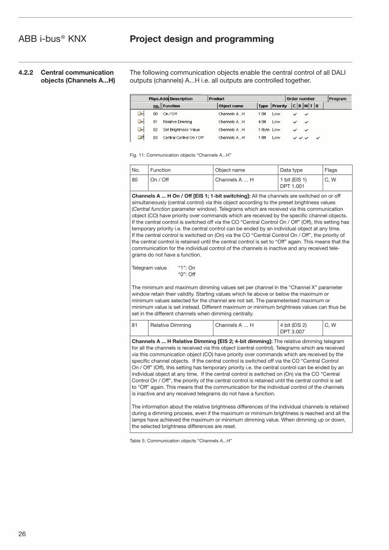
The following communication objects enable the central control of all DALI outputs (channels) A...H i.e. all outputs are controlled together.
Fig. 11: Communication objects “Channels A...H”
No. Function Object name Data type Flags
80 On / Off Channels A … H 1 bit (EIS 1) DPT 1.001
C, W
Channels A ... H On / Off [EIS 1; 1-bit switching]: All the channels are switched on or off simultaneously (central control) via this object according to the preset brightness values (Central function parameter window). Telegrams which are received via this communication object (CO) have priority over commands which are received by the specific channel objects. If the central control is switched off via the CO “Central Control On / Off” (Off), this setting has temporary priority i.e. the central control can be ended by an individual object at any time. If the central control is switched on (On) via the CO “Central Control On / Off”, the priority of the central control is retained until the central control is set to “Off” again. This means that the communication for the individual control of the channels is inactive and any received tele-grams do not have a function.
Telegram value “1”: On “0”: Off
The minimum and maximum dimming values set per channel in the “Channel X” parameter window retain their validity. Starting values which lie above or below the maximum or minimum values selected for the channel are not set. The parameterised maximum or minimum value is set instead. Different maximum or minimum brightness values can thus be set in the different channels when dimming centrally.
81 Relative Dimming Channels A … H 4 bit (EIS 2) DPT 3.007
C, W
Channels A ... H Relative Dimming [EIS 2; 4-bit dimming]: The relative dimming telegram for all the channels is received via this object (central control). Telegrams which are received via this communication object (CO) have priority over commands which are received by the specific channel objects. If the central control is switched off via the CO “Central Control On / Off” (Off), this setting has temporary priority i.e. the central control can be ended by an individual object at any time. If the central control is switched on (On) via the CO “Central Control On / Off”, the priority of the central control is retained until the central control is set to “Off” again. This means that the communication for the individual control of the channels is inactive and any received telegrams do not have a function.
The information about the relative brightness differences of the individual channels is retained during a dimming process, even if the maximum or minimum brightness is reached and all the lamps have achieved the maximum or minimum dimming value. When dimming up or down, the selected brightness differences are reset.
Table 5: Communication objects “Channels A...H”
Project design and programming
27
ABB i-bus® KNX Project design and programming
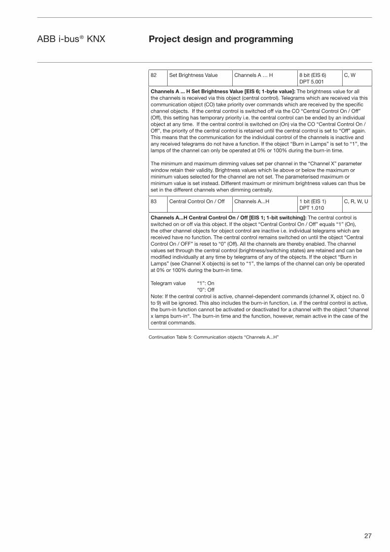
82 Set Brightness Value Channels A … H 8 bit (EIS 6) DPT 5.001
C, W
Channels A ... H Set Brightness Value [EIS 6; 1-byte value]: The brightness value for all the channels is received via this object (central control). Telegrams which are received via this communication object (CO) take priority over commands which are received by the specific channel objects. If the central control is switched off via the CO “Central Control On / Off” (Off), this setting has temporary priority i.e. the central control can be ended by an individual object at any time. If the central control is switched on (On) via the CO “Central Control On / Off”, the priority of the central control is retained until the central control is set to “Off” again. This means that the communication for the individual control of the channels is inactive and any received telegrams do not have a function. If the object “Burn in Lamps” is set to “1”, the lamps of the channel can only be operated at 0% or 100% during the burn-in time.
The minimum and maximum dimming values set per channel in the “Channel X” parameter window retain their validity. Brightness values which lie above or below the maximum or minimum values selected for the channel are not set. The parameterised maximum or minimum value is set instead. Different maximum or minimum brightness values can thus be set in the different channels when dimming centrally.
83 Central Control On / Off Channels A...H 1 bit (EIS 1) DPT 1.010
C, R, W, U
Channels A...H Central Control On / Off [EIS 1; 1-bit switching]: The central control is switched on or off via this object. If the object “Central Control On / Off” equals “1” (On), the other channel objects for object control are inactive i.e. individual telegrams which are received have no function. The central control remains switched on until the object “Central Control On / OFF” is reset to “0” (Off). All the channels are thereby enabled. The channel values set through the central control (brightness/switching states) are retained and can be modified individually at any time by telegrams of any of the objects. If the object “Burn in Lamps” (see Channel X objects) is set to “1”, the lamps of the channel can only be operated at 0% or 100% during the burn-in time.
Telegram value “1”: On “0”: OffNote: If the central control is active, channel-dependent commands (channel X, object no. 0 to 9) will be ignored. This also includes the burn-in function, i.e. if the central control is active, the burn-in function cannot be activated or deactivated for a channel with the object “channel x lamps burn-in“. The burn-in time and the function, however, remain active in the case of the central commands.
Continuation Table 5: Communication objects “Channels A...H”

28
ABB i-bus® KNX Project design and programming
16 lightscenes can be activated via the parameter setting. The scenes can be defined by the ETS entries or set individually by the user according to personal requirements via the individual object. It is possible for each scene to disable the overwriting of the brightness values during an ETS download. The individually set brightness values of the lightscene are hereby retained during an ETS download.
There are separate communication objects for recall or store the 16 lightscenes. There is a further 8-bit communication object available, with which each one of the 16 lightscenes can be stored or retrieved via an 8-bit code.
Fig. 12 : Communication objects “Recall Lightscene x/y”
No. Function Object name Data type Flags
84 Recall Scene Lightscene 1/2 1 bit (EIS 1) DPT 1.006
C, W
85 Recall Scene Lightscene 3/4 1 bit (EIS 1) DPT 1.006
C, W
86 Recall Scene Lightscene 5/6 1 bit (EIS 1) DPT 1.006
C, W
87 Recall Scene Lightscene 7/8 1 bit (EIS 1) DPT 1.006
C, W
88 Recall Scene Lightscene 9/10 1 bit (EIS 1) DPT 1.006
C, W
89 Recall Scene Lightscene 11/12 1 bit (EIS 1) DPT 1.006
C, W
90 Recall Scene Lightscene 13/14 1 bit (EIS 1) DPT 1.006
C, W
91 Recall Scene Lightscene 15/16 1 bit (EIS 1) DPT 1.006
C, W
Lightscene X/Y Recall Scene [EIS 1; 1-bit switching]: The scenes are retrieved via this object. On receipt of a telegram, channels which are assigned to the scene are set to the stored or parameterised brightness values. The communication objects are only visible if the scenes have been activated in the Scenes parameter window.
Telegram value “0”: Recall scene X “1”: Recall scene Y
Table 6: Communication objects “Recall Lightscene x/y”
4.2.3 Lightscene
communication objects

29
ABB i-bus® KNX Project design and programming
With these communication objects, lightscenes can be stored individually e.g. with a push button or another operating device.
Fig. 13: Communication objects “Store Lightscene x/y”
No. Function Object name Data type Flags
92 Store Scene Lightscene 1/2 1 bit (EIS 1) DPT 1.006
C, W
93 Store Scene Lightscene 3/4 1 bit (EIS 1) DPT 1.006
C, W
94 Store Scene Lightscene 5/6 1 bit (EIS 1) DPT 1.006
C, W
95 Store Scene Lightscene 7/8 1 bit (EIS 1) DPT 1.006
C, W
96 Store Scene Lightscene 9/10 1 bit (EIS 1) DPT 1.006
C, W
97 Store Scene Lightscene 11/12 1 bit (EIS 1) DPT 1.006
C, W
98 Store Scene Lightscene 13/14 1 bit (EIS 1) DPT 1.006
C, W
99 Store Scene Lightscene 15/16 1 bit (EIS 1) DPT 1.006
C, W
Lightscene X/Y Store Scene [EIS 1; 1-bit switching]: The scenes are stored via this object. On receipt of a telegram, the current brightness values of all the channels which are assig-ned to the scene are stored. The next time the scene is recalled, all the channels which are assigned to the scene are set to these stored brightness values. The communication objects are only visible if the scenes have been activated in the Scenes parameter window and the parameter option “Permit storing of lightscenes” has been set to “yes”.
Telegram value “0”: Store scene X “1”: Store scene Y
Table 7: Communication objects “Store Lightscene x/y”
30
ABB i-bus® KNX Project design and programming
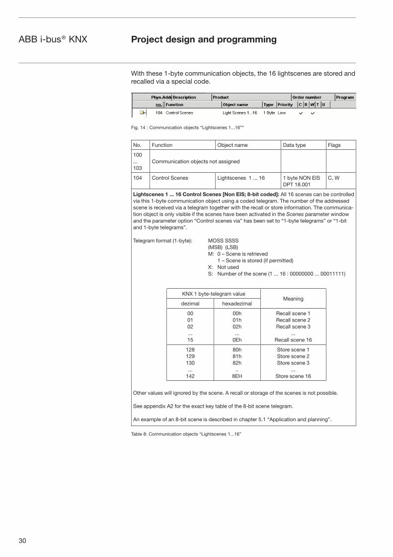
With these 1-byte communication objects, the 16 lightscenes are stored and recalled via a special code.
Fig. 14 : Communication objects “Lightscenes 1...16”“
No. Function Object name Data type Flags
100 ... 103
Communication objects not assigned
104 Control Scenes Lightscenes 1 ... 16 1 byte NON EISDPT 18.001
C, W
Lightscenes 1 ... 16 Control Scenes [Non EIS; 8-bit coded]: All 16 scenes can be controlled via this 1-byte communication object using a coded telegram. The number of the addressed scene is received via a telegram together with the recall or store information. The communica-tion object is only visible if the scenes have been activated in the Scenes parameter window and the parameter option “Control scenes via” has been set to “1-byte telegrams” or “1-bit and 1-byte telegrams”.
Telegram format (1-byte): MOSS SSSS (MSB) (LSB) M: 0 – Scene is retrieved 1 – Scene is stored (if permitted) X: Not used S: Number of the scene (1 ... 16 : 00000000 ... 00011111)
Other values will ignored by the scene. A recall or storage of the scenes is not possible.
See appendix A2 for the exact key table of the 8-bit scene telegram.
An example of an 8-bit scene is described in chapter 5.1 “Application and planning”.
Table 8: Communication objects “Lightscenes 1...16”
KNX 1 byte-telegram valueMeaning
dezimal hexadezimal
000102...15
00h01h02h...
0Eh
Recall scene 1Recall scene 2Recall scene 3
...Recall scene 16
128129130...
142
80h81h82h..
8EH
Store scene 1Store scene 2Store scene 3
...Store scene 16

31
ABB i-bus® KNX Project design and programming
The following communication objects are only activated and visible if the corresponding parameter setting has been carried out. The KNX can be monitored with these communication objects. The number of DALI devices can be fixed for continious monitoring.
Fig. 15: “General” communication objects
No. Function Object tname Data type Flags
105 Communication object not assigned
106 Telegr. Fault 230 VAC General 1 bit (EIS 1) DPT 1.006
C, R, T
General Fault 230 VAC [EIS 1; 1-bit switching]: If the 230 VAC supply voltage of the DALI Gateway should fail for more than 5 seconds, a fault telegram is sent immediately. The communication object is only visible if the parameter “Send telegram ‘Fault 230 VAC’” is set to “yes” in the Status parameter window.
Telegram value “1”: Fault “0”: No fault
107 Fault Acknowledgement General 1 bit (EIS 1) DPT 1.003
C, W
General Fault Acknowledgement [EIS 1; 1-bit switching]: The 1-bit input communication object enables both the reset of the 230 V AC fault signal and the ballast, lamp and DALI fault signals of the individual channels. The communication object is only visible if the parameter “Acknowledge faults” is activated in the Status parameter window. The fault(s) is (are) only reset after an acknowledgement if the corresponding fault(s) has (have) been rectified.
Telegram value “1”: Reset fault(s) “0”: No function
108 Telegr. Communication send
General 1 bit (EIS 1) DPT 1.002
C, R, T
General Telegr. Communication send [EIS 1; 1-bit switching]: To regularly check the presence of the DALI Gateway on the KNX, a monitoring telegram can be sent cyclically on the bus. The communication object is only visible if the parameter “Send/receive communication telegram cyclically” has been set to “send telegram” or “send/receive telegram” in the Status parameter window.
Telegram value “1” : Status
Table 9: Communication objects “General”
4.2.4 General communication
objects

32
ABB i-bus® KNX Project design and programming
109 Telegr. Communication receive
General 1 bit (EIS 1) DPT 1.002
C, W
General Telegr. Communication receive [EIS 1; 1-bit switching]: The DALI Gateway can receive a “1” telegram via this communication object which another KNX device (e.g. diagnostics module) sends cyclically. On receipt of the telegram, the communication capability of the bus can be monitored. If the DALI Gateway does not receive a “1” telegram at the communication object “Telegr. Communication receive” within a specific time interval, a fault in the KNX communication path is assumed and the response defined in the General parameter window is carried out. The DALI Gateway goes into a safety state and does not process any telegrams. Incoming telegrams are only processed again when a “1” is received again at the communication object “Telegr. Communication receive”.
The time span of the receiving interval can be set in the Status parameter window under “Transmission / receive period”.
110 Detect Ballasts General 1 bit (EIS 1) DPT 1.010
C, W
General Detect Ballasts [EIS 1; 1-bit switching]: To be able to correctly detect a fault in a ballast, the DALI Gateway must identify all the connected DALI devices and thereby know the number of DALI devices per channel that need to be monitored. This identification process runs independently and fully automatically in the background if it has been initiated by this communication object. An automatic detection e.g. after a bus or mains voltage recovery does not take place. After approx. 60 seconds, all the DALI devices are detected and the failure of a ballast can be correctly established.
The activation should be carried out directly after commissioning or when extending or redu-cing the DALI devices. The DALI devices are continually monitored, independence the lamp is activated or deactivated. The DALI devices must be installed properly and supplied with operating voltage if necessary.
Telegram value “1”: Start ballast detection process “0”: No function
Continuation Table 9: Communication objects “General”

33
ABB i-bus® KNX
The parameters and parameter windows for the operation and programming of the application “Dim Slave Lightscenes Dynamic 8f” are described in more detail in the following section.
The number of parameter windows can vary depending on the parameter setting.
When the application software “Dim Slave Lightscenes Dynamic 8f” is configured for the first time, the parameter options are preprogrammed with a specific basic setting (default settings). The default settings are highlighted in the following diagrams.
The first parameter window that is shown when the “Edit Parameter” dialog is retrieved appears as follows:
Fig. 16: First parameter window when “Edit Parameters” dialog is retrieved (default setting)
4.3 Description
of the parameters
Project design and programming
34
ABB i-bus® KNX Project design and programming
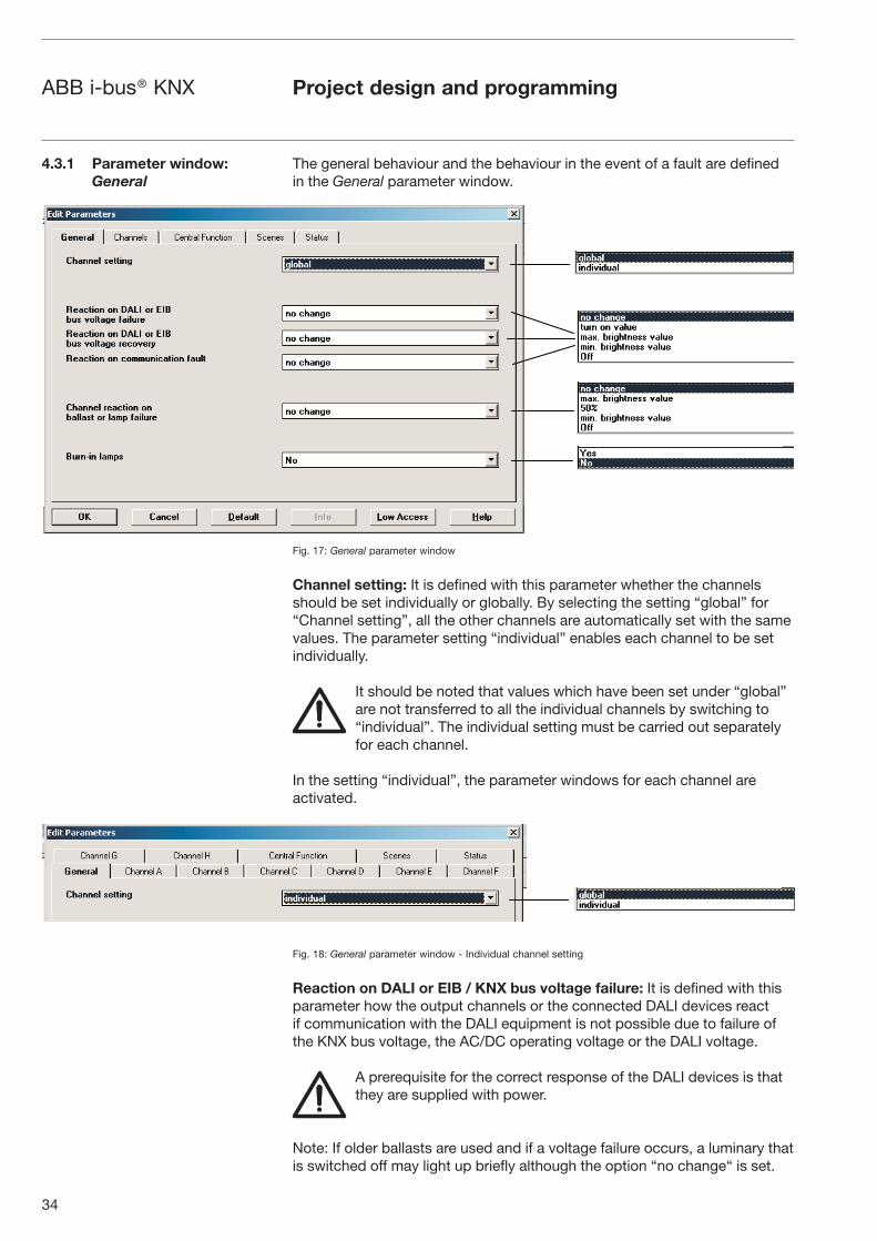
The general behaviour and the behaviour in the event of a fault are defined in the General parameter window.
Fig. 17: General parameter window
Channel setting: It is defined with this parameter whether the channels should be set individually or globally. By selecting the setting “global” for “Channel setting”, all the other channels are automatically set with the same values. The parameter setting “individual” enables each channel to be set individually.
It should be noted that values which have been set under “global” are not transferred to all the individual channels by switching to “individual”. The individual setting must be carried out separately for each channel.
In the setting “individual”, the parameter windows for each channel are activated.
Fig. 18: General parameter window - Individual channel setting
Reaction on DALI or EIB / KNX bus voltage failure: It is defined with this parameter how the output channels or the connected DALI devices react if communication with the DALI equipment is not possible due to failure of the KNX bus voltage, the AC/DC operating voltage or the DALI voltage.
A prerequisite for the correct response of the DALI devices is that they are supplied with power.
Note: If older ballasts are used and if a voltage failure occurs, a luminary that is switched off may light up briefly although the option “no change“ is set.
4.3.1 Parameter window:
General

35
ABB i-bus® KNX Project design and programming
Reaction on DALI or EIB / KNX bus voltage recovery: It is defined with this parameter how the output channels or DALI devices react if the KNX supply voltage, the operating voltage and the DALI control voltage are restored. (The DALI equipment must be supplied with voltage).
If the supply voltage of the DALI devices should only be available at a later time, the current brightness of the associated channel is set within 1 second following recovery of the supply voltage.
The reset of the ballast fault is carried out after a maximum of 45 seconds. This time is dependent on the number of DALI devices that are connected to the channel.
Reaction on communication fault: It is defined with this parameter how the DALI output channels or DALI devices are set if voltage is present but no monitoring communication telegram with the value “1” has been received via the communication object “Telegr. Communication receive” within the defined receiving interval. The time span of the receiving interval can be set in the Status parameter window under “Transmission / receive period”. If no “1” telegram is received during this period, the DALI Gateway adopts a safety state. The connected DALI devices can be parameterised in the following way:
• “no change” (channels retain their brightness value, any started timer operations are continued)
• “turn on value” (all channels are set to the starting value)
• “max. brightness value” (all channels are set to the maximum dimming value)
• “min. dimming value” (all channels are set to the minimum dimming value)
• “Off” (all channels are switched off)
The DALI Gateway does not process any telegrams until a “1” telegram is received again via the communication object “Telegr. Communication receive”.
Channel reaction on ballast or lamp failure: To enable the maintenance personnel to find the channel with the faulty lamp or ballast easily, the reaction of the output channel or electronic ballast in the event of a fault can be defined.
Note: The fault can also be an interruption in the supply voltage to the ballast.
Burn in lamps: Continuous dimming of lamps which are not burned in can lead to the maximum indicated brightness of the lamp not being reached and thus the required brightness level in the room cannot be set.
To guarantee the optimum life expectancy of the lamps and the correct function of the electronic ballasts and lamps in the dimming state, many lamps (filled with gas) when they are first used must be operated for a specific number of hours at 100% brightness before they can be dimmed continuously.

36
ABB i-bus® KNX Project design and programming
If the function “Burn in lamps” is activated and a “Burn in Lamps” telegram has been received, the lamps of the channel can only be operated at 0% (Off) or 100% brightness for the parameterised burn-in time. This applies regardless of the other dimming, ON/OFF and lightscene brightness values which have been set. The burn-in time take priority over all other settings. Once the burn-in time has elapsed or the function has been deactivated (communication object “Channel X Burn in Lamps” equals “0”), the channel can be dimmed as usual and the programmed lightscenes can be retrieved.
The burn-in time is only counted if a DALI device is connected to the chan-nel and is ready for operation (supplied with power).
On KNX bus voltage failure, the burn-in time function remains activated and counts the operating time of the DALI device.
On failure of the 230 V AC/DC operating voltage, the information about the previously elapsed burn-in time is lost. After recovery of the operating voltage, the burn-in time function is deactivated again.
Lamp burn-in period in hours (1 – 255): The burn-in time can be set in hours with this parameter. The recommended burn-in time of the lamp must be taken from the technical data of the appropriate lamp manufacturer.
Fig. 19: General parameter window - Burn-in time of lamps
...

37
ABB i-bus® KNX Project design and programming
In the parameter window Channel X or Channels (for global channel configuration), the settings for the individual channels or for all the channels together are carried out.
The parameter windows Channel B to H are only visible if the setting “individual” has been selected for “Channel setting” in the General parameter window.
Fig. 20: Channel X – Normal operating mode
In normal mode, the channel functions as a standard DALI dimming output.
Brightness value when turned on: This parameter indicates the brightness value with which the DALI device switches on after receipt of an ON telegram “1”. If a value should be set which lies outside the minimum or maximum dimming values, the brightness is restricted during operation to the minimum or maximum dimming limit values. If the channel is already switched on at any brightness value and then receives an ON telegram “1”, the parameterised starting value is set.
4.3.2 Parameter window:
Channel X
4.3.2.1 “Normal” operating mode
...
...
...
...
...
...

38
ABB i-bus® KNX Project design and programming
Minimal brightness value: The minimum brightness value which the DALI device should adopt when dimming darker or setting brightness values is defined via this parameter. The absolute minimal brightness value (back-ground brightness) which the ballast/lamp combination can adopt is ma-nufacturer-specific and typically lies between 1% and 5% of luminous flux. This luminous flux corresponds with a digital DALI dimming value between 85 and 126 digits. On the other hand this corresponds with a Percentage brightness value between 33% and 50%. More information about the DALI dimming curve you can find in chapter 1.2.5.
This means that a DALI ballast with a luminous flux between 3…100% (see printing on ballast) will limited the brightness le-vel to a minimal dimming level of 50% brightness, independent of the parameterization of the DALI-Gateway. To avoid such a limitation, suitable ballast with a dimming range of 1%...100% or 0.1%...100% have to be used.
If a minimum dimming value is set which lies above the maximum dimming value, the following is set: minimum dimming value = maximum dimming value. If the function “Burn in lamps” is activated, the lamp is only operated at 0% (Off) or 100% brightness, regardless of this setting.
If a brightness value should be received via the communication object “Set Brightness Value” which lies below the preset minimum dimming value, the minimum dimming value is set.
The minimum dimming value set per channel continues to be valid for central commands.
Maximal brightness value: The maximum brightness value which the DALI device should adopt when dimming darker or setting brightness values is defined via this parameter. If a maximum dimming value is set which lies below the minimum dimming value, the following is set: maximum dimming value = minimum dimming value. If the function “Burn in lamps” is activa-ted, the lamp is only operated at 0% (Off) or 100% brightness, regardless of this setting. If a brightness value should be received via the communication object “Set Brightness Value” which lies above the preset maximum dimming value, the maximum dimming value is set.The maximum dimming value set per channel continues to be valid for central commands.
Permit channel to be turned on via dimming telegram: The channel can be switched on via dimming if “yes” is selected.
Permit channel to be turned off via dimming telegram: The channel can be switched off via dimming if “yes” is selected.
Dimming period to reach turn on brightness resp. off state (Object:
On/Off): This parameter determines the period which a dimming process requires from switching on at 0% brightness to the starting value. The same speed applies for switching off from the set brightness value to the OFF value. This dimming period only affects dimming commands which are received via ON/OFF telegrams. A soft start or soft stop can be set with this parameter. In the setting “constant dimming speed”, the same speed is used (adjustable under “Dimming speed, time for 0-100%”), regardless of the set brightness value.

39
ABB i-bus® KNX
This means that the ON/OFF value is not achieved at the same time but there is no unnecessarily long delay until a lamp switches from e.g. 30% brightness to the OFF state.
Setting brightness value turns channel on: If it should be possible to switch on from the OFF state via a dimming command “Set Brightness Value”, this must be enabled with the setting “yes”.
Dimming period to reach set brightness value (Object: Set Brightness
Value): This parameter indicates the period in which a dimming process is carried out from 0% to the starting value. This dimming period only affects dimming commands which are received via the communication object “Set Brightness Value”.
Dimming speed, time for 0...100% (Object: Relative Dimming): This para-meter indicates the time for carrying out a dimming process from 0...100%. This dimming time only affects dimming commands which are received via the communication object “Relative Dimming”.
When selecting all the dimming periods, the following should be noted: depending on the lamp, stepwise dimming can occur when the dimming speeds are too fast or the dimming times are too short. The reason for this is that the dimming steps are defined in the norm in order to achieve a logarithmic dimming curve which appears as linear to the human eye.
Project design and programming
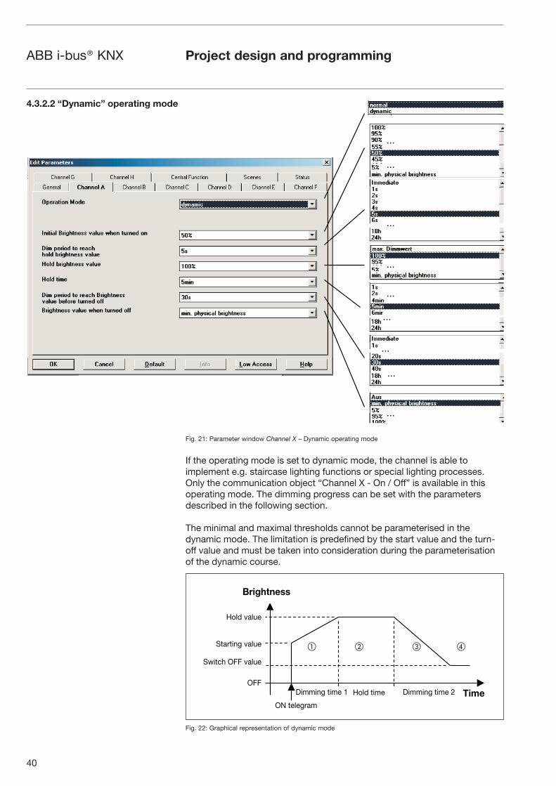
40
ABB i-bus® KNX Project design and programming
Fig. 21: Parameter window Channel X – Dynamic operating mode
If the operating mode is set to dynamic mode, the channel is able to implement e.g. staircase lighting functions or special lighting processes. Only the communication object “Channel X - On / Off” is available in this operating mode. The dimming progress can be set with the parameters described in the following section.
The minimal and maximal thresholds cannot be parameterised in the dynamic mode. The limitation is predefined by the start value and the turn-off value and must be taken into consideration during the parameterisation of the dynamic course.
Fig. 22: Graphical representation of dynamic mode
...
...
...
...
...
...
...
...
...
4.3.2.2 “Dynamic” operating mode
Brightness
Time
Hold value
Starting value
Switch OFF value
OFFDimming time 1 Dimming time 2Hold time
ON telegram
� � � �
41
ABB i-bus® KNX Project design and programming
Any values can be set for the starting, hold and switch OFF values. It is therefore possible to implement very specific or special dimming processes e.g. daylight simulation.
Initial brightness value when turned on: This parameter indicates the starting brightness value with which the DALI devices should switch on after receipt of an ON telegram.
Brightness value when turned off: This parameter indicates the final brightness value which the DALI devices should have when they are switched off i.e. at the end of the dimming progression.
Hold brightness value: This parameter indicates the brightness value which the DALI devices should adopt during the hold period.
Dimming period to reach hold brightness value: This parameter indicates the period during which the DALI devices should have modified their brightness from the starting value to the hold dimming value.
Hold time: This parameter indicates the period during which the DALI devices should retain a constant brightness level (= hold dimming value).
Dimming period to reach brightness value before turned off: This parameter indicates the period during which the DALI devices should have modified their brightness from the hold dimming value to the switch OFF value.
Behaviour on retriggering:
If a new trigger (telegram “Channel X - On / Off”) is carried out during phase �, the dynamic function proceeds unchanged. In the event of an ON telegram in phase �, the hold time � is restarted. An ON telegram “1” in phase � or � causes phases � and � to restart.
In the event of an OFF telegram (“Channel X - On / Off” = “0”) in phase � or �, phase � is started immediately. If an OFF telegram is received in phase � or �, the dynamic mode continues unchanged until the switch OFF value is reached or it is retained.
An example of staircase lighting control is described in chapter 5.3 “Application and planning”.
Minimal brightness value: The minimal brightness value which the DALI device should adopt when dimming darker or setting brightness values is defined via this parameter. The minimal brightness value is not considered during the dynamic mode (e.g. staircase function). However the minimal brightness value is almost active during the scene function. The technical features defined in the “normal” mode are further more admissible.
Maximal brightness value: The maximal brightness value which the DALI device should adopt when dimming higher or setting brightness values is defined via this parameter. The maximal brightness value is not considered during the dynamic mode (e.g. staircase function). However the maximal brightness value is almost active during the scene function. The technical features defined in the “normal” mode are further more admissible.

42
ABB i-bus® KNX Project design and programming
The DALI Gateway can also be operated as a slave. In slave mode, the channel is priority controlled via an 8-bit communication object. This opera-ting mode is activated and deactivated per channel (DALI output) as required via a communication object “Channel X - Slave Operation On / Off”. In slave mode, it is possible to implement central lighting control in addition to the standard dimming functionality. A master control unit (e.g. the lighting controller LR/S 2.2.1 or presence detector PM/A 2.1) sends brightness va-lues in an 8-bit format which controls the DALI output via the DALI Gateway. The 1-byte control value is transferred to the DALI Gateway via the commu-nication object “Channel X - Set Brightness Value”.
After switching on slave mode (value “1” at the communication object “Channel X - Slave Operation On / Off”), the last brightness value received by the communication object “Channel X - Set Brightness Value” is set. If slave mode is switched on, the brightness can only be controlled via the object “Channel X - Set Brightness Value”. The communication objects “Channel X - On / Off” and “Channel X - Relative Dimming” are disabled i.e. telegrams received at this object are not executed.
After switching off slave mode (value “0” at the communication object “Channel X - Slave Operation On / Off”), the current brightness value is retained. The control of the channel via the objects “Channel X - On / Off” and “Channel X - Relative Dimming” is enabled again.
Central control has a higher priority than slave mode. After switching off the central control function, operation reverts to slave mode again.
4.3.2.3 „Slave“ mode

43
ABB i-bus® KNX Project design and programming
4.3.3 Parameter window:
Central function
The settings for the simultaneous control of all the channels (central control) are carried out in the parameter window Central function.
Fig. 23: Central function parameter window – Channels A....H
The functionality of the individual parameters in the central control function corresponds to the parameters in the Channel X parameter window in nor-mal mode. The description of the parameters should be taken from section 4.3.2.1.One exception is the parameter “Brightness value when turned on”. In the central function, one of 16 scenes can be retrieved in addition to the values explained in the parameter window Channel X.On receipt of an ON/OFF, dimming or brightness value setting telegram, all the channels react in the same way and execute the command, regardless of the previous state of the channel. This option enables the simple implementa-tion of central control functions e.g. for security or maintenance applications. This means that during the dimming process, the brightness differences between the channels will remain even if the maximal or minimal brightness status is used as the starting point for dimming. A detailed description of the scenic dimming process can be found in chapter 3.5.In the central function, the “minimum dimming value” and “maximum dim-ming value” defined in the parameter window Channels or Channel X exist as limit values for the channels. If the minimum dimming value should be smaller than a physically possible dimming value of a DALI device, this channel is automatically set to the minimum physically possible dimming value (back-ground brightness).Channels which have an active “Burn in lamps” function, continue to be operated only at 0% (Off) or 100%, regardless of the central dimming value commands. These settings and telegrams which are received via the corresponding communication objects have priority over settings and commands which are assigned to the specific channels.The minimum and maximum brightness values parameterised per channel in the “Channel X” parameter window are retained in the central function and can differ in the individual channel.
...
...
...
...
...
...

44
ABB i-bus® KNX Project design and programming
4.3.4 Parameter window:
Scenes
The general settings for the lightscenes (maximum 16) are carried out in the Scenes parameter window.
Fig. 24: Scenes parameter window - General scene parameters
Activate lightscenes: The lightscenes (max. 16) are activated with this parameter. The number of visible communication objects and parameter windows changes accordingly.
Control scenes via: Lightscenes can be retrieved and saved via 1-bit and/or 1-byte telegrams. The number and type of the visible communication objects changes according to the selected setting.
With 1-bit control, the telegram value has the following function:Telegram value “0” = Recall scene 1 Telegram value “1” = Recall scene 2
With the 1-byte telegram value, the following applies:
KNX 1 byte telegram valueMeaning
dezimal hexadezimal
0001...15
00h01h...
0EH
Recall scene 1 Recall scene 2
...Recall scene 16
128129...
142
80h81h...
8EH
Store scene 1 Store scene 2
...Store scene 16
Note: The lightscene settings are also stored in the DALI Gateway after a bus voltage or supply voltage failure. If a ballast should be replaced, the lightscenes are immediately available again without further commissioning.

45
ABB i-bus® KNX Project design and programming
The settings for the individual scenes are carried out in the parameter window Scene X (X = 1 to 16). The parameter window is only visible if the parameter “Activate lightscenes” has been activated (yes) in the Scenes parameter window.
Fig. 25: Scene X parameter window – Setting scenes
Overwrite scene at download:
With the setting “no”, the current scene brightness values which are stored in the gateway and the DALI devices are not overwritten during an ETS download. The stored scene brightness values are retained.
Note: This can mean that the brightness values which are displayed in the Scene X parameter window do not match the scene brightness values that are actually stored in the gateway and in the DALI devices after an ETS download.
The setting “yes” mean that the scene brightness values which are stored in the DALI devices are overwritten during an ETS download by the brightness values set in ETS.
Transition time for lightscene: This parameter sets the period for the dim-ming process to be concluded for all the lamps when the scene is retrieved. This means e.g. Channel A which should dim from 10% to 100% and Channel B which should dim from 90% to 100% reach their final dimming values at the same time. This transition time is not dependent on the dimming speeds set for the channels.
4.3.5 Parameter window:
Scene X
...
...

46
ABB i-bus® KNX Project design and programming
Channel X: Lightscene value: This parameter indicates the brightness value as a percentage which is adopted by the DALI output and the connected DALI devices when the scene is retrieved. The lightscene value has the default setting of 50% brightness. In the setting “no change”, the current brightness value of this channel is not influenced when the scene is retrieved i.e. the channel is not part of the scene. Even when a manual change is made to the channel brightness and the lightscenes are saved again, the channel remains unchanged.
If the set scene brightness value lies above or below the set minimum or maximum value of the corresponding channel (see parameter window Channel X), this value is stored in the scene but automatically set to the minimum or maximum brightness value of the corresponding channel when the scene is retrieved.

47
ABB i-bus® KNX Project design and programming
4.3.6 Parameter window:
Status
The behaviour of the status and fault communication objects is defined in the Status parameter window. The detection of a fault can take up to 30 seconds depending on the number of electronic ballasts.
Fig. 26: Status parameter window – Status settings and fault signals
Send telegram “Status On/Off”: In the setting “no”, the function and the communication objects are not available. In the parameter setting “only on read request”, the object value “Channel X - Telegr. Status On / Off” can only be read out after a read request. In the parameter setting “on change of status”, the current switching state is sent on a change.
Send telegram “Status Brightness Value”: In the setting “no”, the function and the communication objects are not available. In the parameter setting “only on read request”, the object value “Channel X - Telegr. Status Bright-ness Value” can only be read out after a read request. In the parameter setting “on change of status”, the current value status is sent on a change. The first status value is reported back immediately after a change and not when the final value is reached. This applies to dimming processes as well as brightness transitions via the object “set brightness value”. As a result, long brightness transitions can be visualized particularly well.
Transmission delay time: Telegram “Status Brightness Value”: With this parameter, the sending of the brightness value telegram is delayed by the set period after a change, in order to avoid an unnecessary bus load. In applications in which brightness control or lighting control is implemented or several channels are operated, it is advisable to set a longer transmission delay time so that the control speed is not influenced by an increased bus load. The period is dependent on the control speed. Once the final dimming value has been reached, there is a delay for the set period until the bright-ness value is sent.

48
ABB i-bus® KNX Project design and programming
Send telegram “Fault Ballast”: In the setting “no”, the function and the communication objects are not available. In the parameter setting “only on read request”, the object value “Channel X - Telegr. Fault Ballast” can only be read out after a read request. In the setting “on change of status”, the current fault status is sent automatically via the communication object following a change.
Send telegram “Fault Lamp”: In the setting “no”, the function and the communication objects are not available. In the parameter setting “only on read request”, the object value “Channel X - Telegr. Fault Lamp” can only be read out after a read request. In the parameter setting “on change of status”, the current fault status is sent after a change.
Send telegram “Fault DALI”: In the setting “no”, the function and the communication objects are not available. In the parameter setting “only on read request”, the object value “Channel X - Telegr. Fault DALI” can only be read out after a read request. In the parameter setting “on change of status”, the current fault status is sent after a change.
Send telegram “Fault 230 VAC”: In the setting “no”, the function and the communication objects are not available. In the parameter setting “only on read request”, the object value “Channel X - Telegr. Fault 230 VAC” can only be read out after a read request. In the parameter setting “on change of status”, the current fault status is sent automatically after a change.
Note: This fault affects the operating voltage of the DALI Gateway and can also be DC operating voltage.
Acknowledge faults: In the setting “no”, a telegram is sent via the KNX via the corresponding communication object when a fault occurs (ballast, lamps, DALI, 230 VAC). As soon as the fault is rectified, a telegram is sent automatically with the value “0”. The change in the error state can last 45 seconds and is dependent on the number of DALI devices connected.
In the setting “yes”, a telegram is also sent when a fault occurs. This fault signal remains set however until the fault is rectified and the fault signal is reset via the communication object “Fault Acknowledgement”. Only then a telegram with the value “0” is sent via the corresponding communication object. This can be very helpful for the detection of sporadic faults or events which take place during unmanned monitoring periods.
Send / receive communication telegram cyclically: In the setting “no”, the functions and the communication objects are not available. The DALI Gateway does not send a monitoring telegram and thus does not check the KNX bus in order to monitor the communication path.In the setting “send telegram”, a telegram is sent cyclically via the KNX to signal the presence of the DALI Gateway.In the setting “receive telegram”, the DALI Gateway expects a cyclically transmitted telegram which indicates the communication capability of the KNX. If the DALI Gateway does not receive a telegram within a specific time interval, a fault in the KNX communication path is assumed and a response defined in the General parameter window (section 4.3.1) is carried out. The time span of the receiving interval can be set in the Status parameter window under “Transmission / receive period”.In the setting “send/receive telegram”, the DALI Gateway sends and receives a monitoring telegram cyclically with which the communication via the KNX is monitored.

49
ABB i-bus® KNX Project design and programming
Transmission / receive period: The parameter is only visible if “Send / receive communication telegram cyclically” is not set to “no”. The set period applies both to the time span between two telegrams which are sent by the DALI Gateway and to the time span in which a telegram should be received for bus monitoring.
It should be ensured that the transmission period of the KNX device which sends the KNX telegram is shorter than the selected receiving time in the DALI Gateway.The time span selected for the transmission/receive period should be as long as possible, depending on the application, in order to keep the bus load as low as possible.
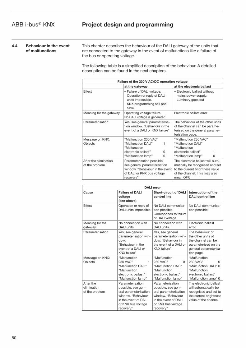
50
ABB i-bus® KNX Project design and programming
4.4 Behaviour in the event
of malfunctions
This chapter describes the behaviour of the DALI gateway of the units that are connected to the gateway in the event of malfunctions like a failure of the bus or operating voltage.
The following table is a simplified description of the behaviour. A detailed description can be found in the next chapters.
Failure of the 230 V AC/DC operating voltage
at the gateway at the electronic ballast
Effect – Failure of DALI voltage:Operation or reply of DALI units impossible.
– KNX programming still pos-sible.
– Electronic ballast without mains power supply:Luminary goes out
Meaning for the gateway Operating voltage failure. No DALI voltage is generated.
Electronic ballast error
Parameterisation Yes, see general parameterisa-tion window. “Behaviour in the event of a DALI or KNX failure”
The behaviour of the other units of the channel can be parame-terised on the general parame-terisation page.
Message on KNX: Objects
“Malfunction 230 VAC”“Malfunction DALI” 1“Malfunction electronic ballast” 0“Malfunction lamp” 0
“Malfunction 230 VAC”“Malfunction DALI”“Malfunction electronic ballast” 1“Malfunction lamp” 0
After the elimination of the problem
Parameterisation possible, see general parameterisation window. “Behaviour in the event of DALI or KNX bus voltage recovery”
The electronic ballast will auto-matically be recognised and set to the current brightness value of the channel. This may also mean OFF.
DALI error
Cause Failure of DALI
voltage
(see above)
Short-circuit of DALI
control line
Interruption of the
DALI control line
Effect Operation or reply of DALI units impossible.
No DALI communica-tion possible.Corresponds to failure of DALI voltage.
No DALI communica-tion possible.
Meaning for the gateway
No connection with DALI units.
No connection with DALI units.
Electronic ballast error
Parameterisation Yes, see general parameterisation win-dow: “Behaviour in the event of a DALI or KNX failure”
Yes, see general parameterisation win-dow: “Behaviour in the event of a DALI or KNX failure”
The behaviour of the other units of the channel can be parameterised on the general parameterisa-tion page.
Message on KNX: Objects
“Malfunction 230 VAC” 1“Malfunction DALI”“Malfunction electronic ballast”“Malfunction lamp”
“Malfunction 230 VAC” 0“Malfunction DALI”“Malfunction electronic ballast”“Malfunction lamp”
“Malfunction 230 VAC” 0“Malfunction DALI” 0“Malfunction electronic ballast”“Malfunction lamp” 0
After the elimination of the problem
Parameterisation possible, see gen-eral parameterisation window. “Behaviour in the event of DALI or KNX bus voltage recovery”
Parameterisation possible, see gen-eral parameterisation window. “Behaviour in the event of DALI or KNX bus voltage recovery”
The electronic ballast will automatically be recognised and set to the current brightness value of the channel.

51
ABB i-bus® KNX Project design and programming
4.4.1 Behaviour
on voltage failure
Failure of the operating voltage
The failure of the operating voltage on the DALI Gateway is indicated by the green operating LED on the front of the device being extinguished. The yellow DALI fault LED also remains switched off as no operating voltage is available for triggering the LED.
The DALI Gateway can also be programmed and parameterised without operating voltage via the KNX connection. Communication with the con-nected DALI devices is not possible.
The communication object “Telegr. Fault 230 VAC” can be activated in the parameter window. Depending on the parameterisation, the fault in the operating voltage is routed automatically via this object or only via a read request.
The 230 VAC fault refers to the operating voltage of the DALI Gateway in general and thus also applies to a DC operating voltage.
By means of the general communication object “Fault Acknowledgement”, the acknowledgement of the fault signals can be parameterised i.e. both the reset of the 230 VAC fault signal and the ballast, lamp and DALI fault signals of the channels is possible.
The failure of the operating voltage means that the DALI power supply in the DALI Gateway is no longer functioning. The communication to the con-nected DALI device is interrupted. In the event of a failure in the operating voltage in test mode, the mode is interrupted and must be restarted after recovery of the operating voltage.
The behaviour of the DALI device cannot be parameterised directly when the operating voltage fails. As a failure in the operating voltage however simultaneously leads to a failure of the DALI bus voltage, the response of the device can be set on the General parameter window via the parameter “Reaction on DALI or EIB / KNX bus voltage failure”. The following options are available for the DALI outputs: no change, turn on value, maximum and minimum dimming value or Off.
Scene sequences or the dynamic operating mode are retained with their current brightness value and are not continued after recovery of the operating voltage. The connected DALI devices adopt the state which was parameterised after bus voltage recovery.
The function of the burn-in time is lost on bus voltage failure and is deacti-vated after voltage recovery. The previously elapsed time is lost.
KNX bus voltage failure
If the DALI Gateway is supplied with AC or DC operating voltage, communi-cation with the connected DALI devices is possible after an KNX bus voltage failure. The manual test function of the DALI outputs (channels) is possible.
The behaviour of the DALI devices can also be defined in the parameters. The parameter “Reaction on DALI or EIB / KNX bus voltage failure” is availa-ble for this purpose in the General parameter window. The following options are available for the DALI outputs: no change, turn on value, maximum and minimum dimming value or Off.

52
ABB i-bus® KNX Project design and programming
Any scene sequences that have been started and the dynamic operating mode (e.g. staircase lighting function) continue to run if “no change” has been selected on the General parameter in the event of bus voltage failure. The DALI faults, ballast and lamp faults are also detected without KNX bus voltage. The corresponding fault telegram cannot be sent if the KNX bus voltage is not present. This means that a DALI fault in the KNX environment is not detected during an KNX bus voltage failure and the fault information is lost. If a faulty lamp is replaced during an KNX bus voltage failure, the telegram “Fault Lamp” with the value “0” (no fault) can likewise not be sent and is lost.
DALI voltage failure
A failure in the DALI voltage (e.g. short circuit) of a channel is indicated by the yellow DALI fault LED which lights up if the operating voltage is applied. Communication with the connected DALI devices of the channel is not possible without DALI voltage.
The behaviour of the DALI Gateway and the connected DALI devices must be parameterised on failure of the DALI voltage.
The parameter “Reaction on DALI or EIB / KNX bus voltage failure” is availa-ble in the General parameter window. The following options are available for the DALI outputs: no change, turn on value, maximum and minimum dim-ming value or Off.
The communication object “Channel X - Telegr. Fault DALI” can be activated in the Status parameter window. Depending on the parameterisation, the disruption in the DALI voltage of the channel is automatically routed via this object or via a read request.
If required, an acknowledgement of the fault signal can be parameterised. The general communication object “Fault Acknowledgement” is available which enables both the reset of the 230 VAC fault signal and the ballast, lamp and DALI fault signals of the individual channels.
The burn-in time function remains active and is continued after voltage recovery for the remaining period.
Operating voltage failure at the DALI operating unit
If the operating voltage of a DALI device (e.g. electronic ballast) fails, the device is no longer able to work. The light goes out.
In the delivery status, the operating units with a DALI interface usually set the luminaries to maximal brightness (100%) when the operating voltage is applied for the first time or when it is restored. This “Power UP Level” is pre-defined by the manufacturer of the electronic ballast. As a result, the electri-cian can switch the DALI illumination on or off, e.g. with an automatic circuit breaker, even if the individual DALI devices have not been addressed yet.

53
ABB i-bus® KNX
4.4.2 Behaviour
on voltage recovery
The 8-fold KNX DALI gateway, DG/S 8.1, interprets a failure of the operat-ing voltage of the DALI devices as a fault of the electronic ballast, since the DALI device does not reply anymore. Once the operating voltage is restored, the electronic ballast is switched on with maximal brightness (100%) as it is requested by the manufacturer. After 1 or 2 seconds, the “recovered” electronic ballast(s) will be set to the brightness that the user has set for the corresponding channel. An explicit parameterisation in the DALI gateway is not provided.
Recovery of the operating voltage
On recovery of the operating voltage on the DALI Gateway, the green operating LED lights up again.
The behaviour of the DALI Gateway and the connected DALI device on recovery of the operating voltage (supply voltage) of the DALI Gateway cannot be parameterised directly.
As a recovery of the operating voltage simultaneously leads to a recovery of the DALI voltage, the behaviour of the DALI devices can be defined in the parameters. The parameter “Reaction on DALI or EIB / KNX bus voltage recovery” in the General parameter window is available for this purpose. The following options are available for the DALI outputs: no change, turn on value, maximum and minimum dimming value or Off.
The communication object “Telegr. Fault 230 VAC” can be activated in the Status parameter window. Depending on the parameterisation, the fault in the operating voltage of the channel is automatically routed via this object or via a read request.
If the fault acknowledgement is activated, the fault signal remains set until the fault is rectified and the fault signal is reset via the communication object “Fault Acknowledgement”. Only then a telegram with the value “0” is sent via the corresponding communication object. This can be very helpful when detecting sporadic errors or events which take place during unmanned monitoring periods.
The function of the burn-in time is lost on bus voltage failure and is deactivated after voltage recovery. The previously elapsed time is lost.
Project design and programming
54
ABB i-bus® KNX Project design and programming
KNX bus voltage recovery
The behaviour of the DALI devices on recovery of the KNX bus voltage can be defined via the parameters. The parameter “Reaction on DALI or EIB / KNX bus voltage recovery” is available for this purpose in the General parameter window. The following options are available for the DALI outputs:
� no change, turn on value
� maximum dimming value
� minimum dimming value
� Off
The information about DALI faults, ballast and lamp faults which have occurred during the KNX voltage failure is routed after KNX bus voltage recovery.
Scenic courses of the dynamic operation stop with their current brightness value and will not be resumed after the recovery of the operating voltage. The connected DALI devices assume the status that was parameterised after the recovery of the bus voltage.
DALI voltage recovery
On DALI voltage recovery, the yellow DALI fault LED is extinguished.
The behaviour of the DALI Gateway and the connected DALI devices on recovery of the DALI voltage can be parameterised.
The parameter “Reaction on DALI or EIB / KNX bus voltage recovery” is available in the General parameter window. The following options are availa-ble for the DALI outputs: no change, turn on value, maximum and minimum dimming value or Off.
The communication object “Telegr. Fault DALI” can be activated in the Status parameter window. Depending on the parameterisation, the recovery of the DALI voltage of the channel is automatically routed via this object or via a read request.
If the fault acknowledgement is activated, the fault signal remains set until the fault is rectified and the fault signal is reset via the communication ob-ject “Fault Acknowledgement”. After the acknowledgement a telegram with the value “0” is sent via the corresponding communication object. This can be very helpful when detecting sporadic errors or events which take place during unmanned monitoring periods.
The function of the burn-in time is lost on bus voltage failure and is deacti-vated after voltage recovery. The previously elapsed time is lost.
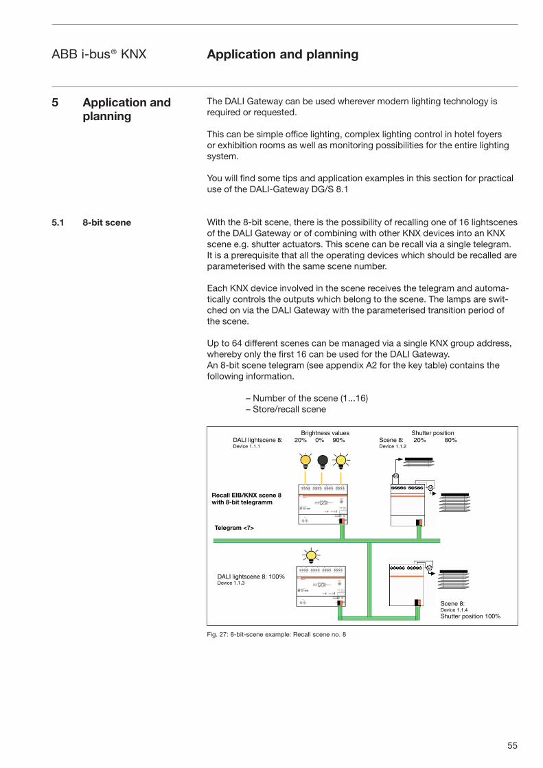
55
ABB i-bus® KNX Application and planning
5 Application and
planning
5.1 8-bit scene
The DALI Gateway can be used wherever modern lighting technology is required or requested.
This can be simple office lighting, complex lighting control in hotel foyers or exhibition rooms as well as monitoring possibilities for the entire lighting system.
You will find some tips and application examples in this section for practical use of the DALI-Gateway DG/S 8.1
With the 8-bit scene, there is the possibility of recalling one of 16 light scenes of the DALI Gateway or of combining with other KNX devices into an KNX scene e.g. shutter actuators. This scene can be recall via a single telegram. It is a prerequisite that all the operating devices which should be recalled are parameterised with the same scene number.
Each KNX device involved in the scene receives the telegram and automa-tically controls the outputs which belong to the scene. The lamps are swit-ched on via the DALI Gateway with the parameterised transition period of the scene.
Up to 64 different scenes can be managed via a single KNX group address, whereby only the first 16 can be used for the DALI Gateway. An 8-bit scene telegram (see appendix A2 for the key table) contains the following information.
– Number of the scene (1...16)– Store/recall scene
Fig. 27: 8-bit-scene example: Recall scene no. 8
Scene 8:Device 1.1.4Shutter position 100%
Brightness valuesDALI lightscene 8: 20% 0% 90%Device 1.1.1
Shutter positionScene 8: 20% 80%Device 1.1.2
Recall EIB/KNX scene 8
with 8-bit telegramm
Telegram <7>
DALI lightscene 8: 100%Device 1.1.3

56
ABB i-bus® KNX Application and planning
Example:
An KNX scene (no. 8) consisting of 4 lamps and 3 shutters which are con-nected to two DALI Gateways and 2 shutter actuators can be recalled via a single KNX telegram. The prerequisite is that all the participants of scene 8 are parameterised accordingly in their devices. After the receipt of the tele-gram, the two DALI Gateways switch on their scene with the number 8. This is carried out with the transition periods which have been set in the gateway. The two shutter actuators move the 3 shutters into the corre sponding positi-on at the same time.
Benefit: The 8-bit scene offers several advantages compared to conven-tional scene programming. On the one hand, only one telegram is sent via the bus when a scene is recalled which is received and converted by all the participants in the scene. On the other hand, the target position of the shutter or the brightness of the DALI devices is stored in the actuator or DALI Gateway and does not need to be transferred via the KNX after each recall.
The scene numbering 1 to 16 is recalled via the KNX with a telegram value of 0 to 15. Refer to the key table in the appendix A.2 for the corresponding scene codes.
Coloured light can be generated with LED technology from the colours red, green and blue. LED strips with the corresponding DALI converters are available which can be connected to the DALI Gateway.
A rail mounted LED strip is connected to three LED converters. Each colour can be addressed individually with KNX push buttons via corre-sponding KNX objects. Each colour can be controlled separately, whereby each colour can be set.
Fig. 28: Example of colour LED system
Repetitive lighting effects can be controlled with the help of slave mode and corresponding KNX devices (e.g. timer). By retrieving a scene or using dynamic mode, different colours can be set and retrieved directly or with specific colour transitions.
+ -
� � DA DA
+ - + -
� � DA DA � � DA DA
RGB+
230 VACEIB / KNX
5.2 Coloured light with
LED technology and DALI
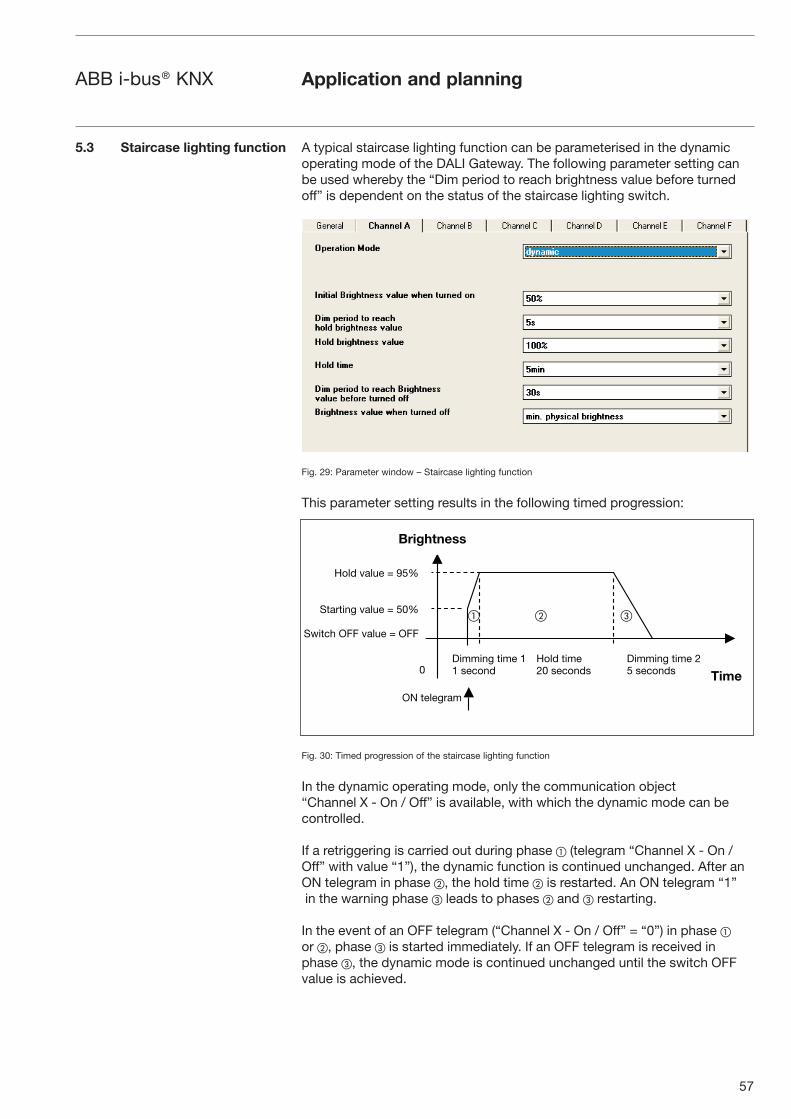
57
ABB i-bus® KNX Application and planning
5.3 Staircase lighting function A typical staircase lighting function can be parameterised in the dynamic operating mode of the DALI Gateway. The following parameter setting can be used whereby the “Dim period to reach brightness value before turned off” is dependent on the status of the staircase lighting switch.
Fig. 29: Parameter window – Staircase lighting function
This parameter setting results in the following timed progression:
Fig. 30: Timed progression of the staircase lighting function
In the dynamic operating mode, only the communication object “Channel X - On / Off” is available, with which the dynamic mode can be controlled.
If a retriggering is carried out during phase � (telegram “Channel X - On / Off” with value “1”), the dynamic function is continued unchanged. After an ON telegram in phase �, the hold time � is restarted. An ON telegram “1” in the warning phase � leads to phases � and � restarting.
In the event of an OFF telegram (“Channel X - On / Off” = “0”) in phase � or �, phase � is started immediately. If an OFF telegram is received in phase �, the dynamic mode is continued unchanged until the switch OFF value is achieved.
Brightness
Time
Hold value = 95%
Starting value = 50%
Switch OFF value = OFF
0Dimming time 11 second
Dimming time 25 seconds
Hold time20 seconds
ON telegram
� � �

58
ABB i-bus® KNX Application and planning
5.4 Facility Management One of the benefits of the DALI standard is the detection and reporting of ballast and lamp faults. This information can be displayed directly or routed to a control unit in order to arrange the appropriate maintenance or service procedures.
The current status of the lighting system is monitored continually or can be queried if required at any point.
Lamp and ballast faults can be detected per channel with the DALI-Gateway DG/S 8.1. It must be taken into account that the exact lamp in the channel cannot be monitored (see lamp fault 2 in the diagram). If each lamp should be monitored individually, only one DALI device is connected per channel (see lamp fault 1). This however, is normally not necessary. In most cases, it is sufficient if the group or strip of luminaires in room or corridor is known, in order to send the maintenance personnel to the correct place with the appropriate information. The faulty lamp is then detected directly on site and can be replaced without a commissioning process.
A fault acknowledgement can be set. This means that the fault signal is only reset once the fault has been acknowledged manually. Otherwise, the DALI Gateway automatically resets the error signal once the fault has been rectified (replacement of the lamp or ballast).
Fig. 31: System representation of a fault signal
Acoustic/visualdisplay
Visual fault displayon a control unit
Fault ack.
Lamp fault 1
Lamp fault 2

59
ABB i-bus® KNX Application and planning
5.5 Assignment of the switch
sensor
The DALI Gateway from ABB opens up a variety of possibilities to the user for operating and adjusting the lighting in a convenient, individual and targeted way. At the same time, a range of safety functions can be taken into account.
Due to this variety of possibilities, the operation should be made easily understandable for the user when planning the switch sensors and other operating elements. Two examples of a possible assignment for a 4-fold switch sensor in an office with two lighting strips and an additional lamp are shown in the following section.
Fig. 32: Office example
Example 1 “Individual solution”
Channel A with lighting strip 1 is controlled via the first push button. A short push button action switches the lighting strip ON/OFF. Lighting strip 1 is dimmed up or down with a long push button action.
The second push button controls lighting strip 2 which is connected to channel B. The function is the same as the first push button.
The additional lamp can be switched with the third push button. If this is a dimmable lamp, the same function can be set as for push button 1.
The shutters are moved UP/DOWN (long push button) via the fourth push button and the louvres are adjusted with a short push button action.
Fig. 33: Push button assignment for “Individual solution”
Lighting strip 1
Lighting strip 2
Lamp
ShutterShutterS
hutte
r
I Lighting strip 0 2
I Lighting strip 0 1
I Table 0 lamp
Shutter< >
Short: Lighting strip 1 ON / OFFLong: Lighting strip 1 Dimming UP / DOWN
Short: Lighting strip 2 ON / OFFLong: Lighting strip 2 Dimming UP / DOWN
Short: Table lamp ON / OFFLong: Table lamp Dimming UP / DOWN
Short: Shutter Louvre adjustment / STOPLong: Shutter UP / DOWN

60
ABB i-bus® KNX Application and planning
Example 2 “Scene solution”
The first push button controls channel A with lighting strip 1 and channel B with lighting strip 2. A short push button action switches the lighting strips on with the brightness value with which they were previously switched off (parameterised). The lighting strips are dimmed up or down with a long push button action.
Scene 1 “Working” is retrieved with push button 2 (short operation ON). Lighting strip 1 and lighting strip 2 are set to 85% brightness. The lighting over the meeting table is switched off.
Scene 2 “Meeting” is retrieved with push button 2 (short operation OFF). Lighting strip 1 is set to 30% brightness while lighting strip 2 is set to 50% brightness. The lighting over the meeting table is switched on with 100% brightness. If the meeting has finished, the scene “Working” is switched on again by pressing ON.
All 3 lamps are switched on and off with a short operation of push button 3. All 2 lamps are dimmed up and down with a long push button action.
The fourth push button is reserved for the shutters.
Fig. 34: Push button assignment for “Scene solution”
A further office and the corridor for example can be controlled with the remaining 5 DALI outputs of the DALI Gateway.
1 Scene 2
I Lighting strip 0 1
I All lamps 0
Shutter< >
Short: Lighting strip 1 ON / OFFLong: Lighting strip 1 Dimming UP / DOWN
ON: Scene 1 “Working”OFF: Scene 2 “Meeting”
Short: All lamps ON / OFFLong: All lamps Dimming UP / DOWN
Short: Shutter Louvre adjustment / STOPLong: Shutter UP / DOWN

61
ABB i-bus® KNX
6 Maintenance
6.1 DALI-Gateway DG/S 8.1
6.2 DALI devices
The maintenance instructions for the DALI-Gateway DG/S 8.1 are described in the following chapter.
The DALI-Gateway DG/S 8.1 is maintenance-free.
In the event of damage (e.g. caused during transportation, storage), no repairs may be carried out.
When the device is opened, the right to claim under guarantee expires.
Cleaning: Dirty devices can be cleaned with a dry cloth. If this is not sufficient, a cloth that has been dampened slightly with a soap solution can be used. Caustic agents or solvents may not be used under any circumstances.
The DALI devices are likewise normally maintenance-free. Possible conditions for maintenance or burning in the lamps must be taken from the corresponding documentation of the individual DALI devices.
Maintenance

62
Appendix
A.1 Overview DALI devices ABB offers a large collection of DALI devices.
There are ECG (electrical ballasts) for T5, T6 and compact fluorescent lamps (e.g. ECG DALI-T5 or TC-L), electronic transformers for low voltage halogen lamps (e.g. ETR one4all), dimmers (e.g. DALI-DU/E300), DALI switch actua-tors (e.g. DSA/S 2.16.1), DALI-LED-Converter (e.g. LED0025) and more in the ABB portfolio.
All DALI components and their technical properties are listed in the low-voltage main catalogue Chapter 14 Lighting equipment.
More information can be found via the following address:
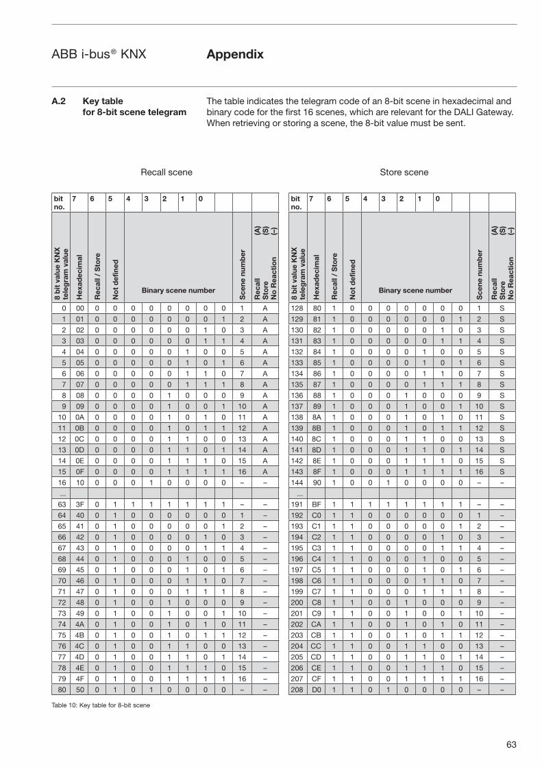
63
ABB i-bus® KNX Appendix
A.2 Key table
for 8-bit scene telegram
The table indicates the telegram code of an 8-bit scene in hexadecimal and binary code for the first 16 scenes, which are relevant for the DALI Gateway.When retrieving or storing a scene, the 8-bit value must be sent.
bit
no.
7 6 5 4 3 2 1 0
8 b
it v
alu
e K
NX
tele
gra
m v
alu
e
He
xa
de
cim
al
Re
ca
ll /
Sto
re
No
t d
efi
ne
d
Binary scene number
Sc
en
e n
um
be
r
Re
ca
ll
(A)
Sto
re
(S)
No
Re
ac
tio
n
(–)
0 00 0 0 0 0 0 0 0 0 1 A
1 01 0 0 0 0 0 0 0 1 2 A
2 02 0 0 0 0 0 0 1 0 3 A
3 03 0 0 0 0 0 0 1 1 4 A
4 04 0 0 0 0 0 1 0 0 5 A
5 05 0 0 0 0 0 1 0 1 6 A
6 06 0 0 0 0 0 1 1 0 7 A
7 07 0 0 0 0 0 1 1 1 8 A
8 08 0 0 0 0 1 0 0 0 9 A
9 09 0 0 0 0 1 0 0 1 10 A
10 0A 0 0 0 0 1 0 1 0 11 A
11 0B 0 0 0 0 1 0 1 1 12 A
12 0C 0 0 0 0 1 1 0 0 13 A
13 0D 0 0 0 0 1 1 0 1 14 A
14 0E 0 0 0 0 1 1 1 0 15 A
15 0F 0 0 0 0 1 1 1 1 16 A
16 10 0 0 0 1 0 0 0 0 – –
...
63 3F 0 1 1 1 1 1 1 1 – –
64 40 0 1 0 0 0 0 0 0 1 –
65 41 0 1 0 0 0 0 0 1 2 –
66 42 0 1 0 0 0 0 1 0 3 –
67 43 0 1 0 0 0 0 1 1 4 –
68 44 0 1 0 0 0 1 0 0 5 –
69 45 0 1 0 0 0 1 0 1 6 –
70 46 0 1 0 0 0 1 1 0 7 –
71 47 0 1 0 0 0 1 1 1 8 –
72 48 0 1 0 0 1 0 0 0 9 –
73 49 0 1 0 0 1 0 0 1 10 –
74 4A 0 1 0 0 1 0 1 0 11 –
75 4B 0 1 0 0 1 0 1 1 12 –
76 4C 0 1 0 0 1 1 0 0 13 –
77 4D 0 1 0 0 1 1 0 1 14 –
78 4E 0 1 0 0 1 1 1 0 15 –
79 4F 0 1 0 0 1 1 1 1 16 –
80 50 0 1 0 1 0 0 0 0 – –
bit
no.
7 6 5 4 3 2 1 0
8 b
it v
alu
e K
NX
tele
gra
m v
alu
e
He
xa
de
cim
al
Re
ca
ll /
Sto
re
No
t d
efi
ne
d
Binary scene number
Sc
en
e n
um
be
r
Re
ca
ll
(A)
Sto
re
(S)
No
Re
ac
tio
n
(–)
128 80 1 0 0 0 0 0 0 0 1 S
129 81 1 0 0 0 0 0 0 1 2 S
130 82 1 0 0 0 0 0 1 0 3 S
131 83 1 0 0 0 0 0 1 1 4 S
132 84 1 0 0 0 0 1 0 0 5 S
133 85 1 0 0 0 0 1 0 1 6 S
134 86 1 0 0 0 0 1 1 0 7 S
135 87 1 0 0 0 0 1 1 1 8 S
136 88 1 0 0 0 1 0 0 0 9 S
137 89 1 0 0 0 1 0 0 1 10 S
138 8A 1 0 0 0 1 0 1 0 11 S
139 8B 1 0 0 0 1 0 1 1 12 S
140 8C 1 0 0 0 1 1 0 0 13 S
141 8D 1 0 0 0 1 1 0 1 14 S
142 8E 1 0 0 0 1 1 1 0 15 S
143 8F 1 0 0 0 1 1 1 1 16 S
144 90 1 0 0 1 0 0 0 0 – –
...
191 BF 1 1 1 1 1 1 1 1 – –
192 C0 1 1 0 0 0 0 0 0 1 –
193 C1 1 1 0 0 0 0 0 1 2 –
194 C2 1 1 0 0 0 0 1 0 3 –
195 C3 1 1 0 0 0 0 1 1 4 –
196 C4 1 1 0 0 0 1 0 0 5 –
197 C5 1 1 0 0 0 1 0 1 6 –
198 C6 1 1 0 0 0 1 1 0 7 –
199 C7 1 1 0 0 0 1 1 1 8 –
200 C8 1 1 0 0 1 0 0 0 9 –
201 C9 1 1 0 0 1 0 0 1 10 –
202 CA 1 1 0 0 1 0 1 0 11 –
203 CB 1 1 0 0 1 0 1 1 12 –
204 CC 1 1 0 0 1 1 0 0 13 –
205 CD 1 1 0 0 1 1 0 1 14 –
206 CE 1 1 0 0 1 1 1 0 15 –
207 CF 1 1 0 0 1 1 1 1 16 –
208 D0 1 1 0 1 0 0 0 0 – –
Recall scene Store scene
Table 10: Key table for 8-bit scene

64
ABB i-bus® KNX Appendix
A.3 Conversion of
older application program
A Conversion of application program V1.0 to V1.1 is possible. With the aid of the conversion it is possible from ETS3 to accept the param-eters and group addresses from previous application programs.
Procedure:
1. Import the current VD3 file into the ETS3 and append a product with the current application program into the project.
2. Click with the right mouse button on the product and select “Convert”.
3. Then follow the instructions
The following application programs can be converted:
Application program Conversion is possible
completely
Dim Slave Light Scenes Dynamic 8f/1a
Dim Slave Light Scenes Dynamic 8f/1.1
Note: Please note that the standard values can be set after conversion of newly added parameters.
4. Then change the existing physical address and delete the old device.

65
ABB i-bus® KNX Appendix
1...10 V technology
Analogue interface for controlling electrical equipment. The brightness is controlled in lighting technology via a polarised voltage at the control input. This voltage is made available by the ballast.Individual addressing and direct addressing of the individual devices is not possible. It is only possible to switch off the devices by disconnecting the mains voltage via a separate switch contact (e.g. relay). The standard for ballasts is DIN EN 60929.
Arbeitsgemeinschaft DALI - AG DALI (Activity Group DALI)
The AG DALI is an amalgamation of manufacturers of controllers, ballasts and DALI devices which is established under the umbrella of the ZVEI. The activity group has set itself the task of developing the DALI standard and carrying out shared marketing activities. The DALI manual for example was issued by the AG DALI. This manual and further information can be found on the home page of the AG DALI under www.dali-ag.org.
Broadcast
Broadcast or broadcast mode is a command which controls all the connec-ted DALI devices together. The DALI devices do not need to be addressed in this operating mode.
DALI (Digital Addressable Lighting Interface)
Digital, manufacturer-neutral standard in lighting technology for bi-directional communication between controllers and electronic equipment with a DALI interface. The norm is standardised in DIN IEC 60929 (appendix E4).64 devices can be addressed. 16 scenes and 16 groups are possible.The digital DALI standard has a typical high level of 16 V DC (max. 20.5 to 11.5 V DC) and a low level of 0 V (max. 4.5 to –4.5 V DC). The usable data transmission rate is 1200 bit/s.The maximum cable length is 300 m. The control cable is not polarity dependent and must have basic insulation (no SELV). Two cables in a 5-core NYM mains cable can be used as a DALI control cable.DALI ballasts have a dimming range of 0.1 to 100%.
DSI (Digital Serial Interface)Older manufacturer-specific digital standard in lighting technology for communication between controllers and electronic equipment with a corresponding DSI interface.The standard was developed by the company TRIDONIC ATCO and is the precursor of the DALI standard without indirect status feedback.
KNX (in the past, European Installation Bus)
KNX is the installation bus for cost-effective and flexible solutions in intelli-gent building technology for commercial and industrial buildings. The KNX standard is a company-neutral standard which has been fixed in the norm EN 50090. KNX devices are checked, registered and certified by the Konnex Association in compliance with the standard.
A.4 Definition of terms
66
ABB i-bus® KNX
The KNX controls, switches and monitors numerous functions in the buil-dings. These include lighting control, maximum-demand monitoring, tempe-rature control, emergency and standby operation, fan control, shutter/roller blind control, timed/remote control, display/logging as well as monitoring and reporting. Weather data can be recorded and integrated in building au-tomation. Using various gateways, it is possible to establish an interface to the Internet, telephone network or subsystems such as DALI, DSI or 1...10 V control technology.A conventional, two-core KNX control cable PYCYM (2x2x0.8 mm) is used as the bus cable. Over 10,000 devices can be connected in 15 areas which contain up to 15 lines.The programming of the system is carried out with the parameterisation software ETS (Engineering Tool Software).
Electrical equipment
All items which are used for the purposes of generating, converting, transferring, distributing and applying electrical energy e.g. machines, transformers, switchgear, measuring equipment, protective devices, cables and devices.Electrical equipment in this manual refers to dimmers, transformers, ballasts, relays etc. which are used to operate electrical lamps.
ETS (Engineering Tool Software)
The programming of the KNX is carried out with ETS. The ETS program makes an effective project design, commissioning and diagnostics tool for the KNX available to the electrical installer.Further information can be procured about EIBA or the Konnex Association.
Ballast
A device for operating gas discharge luminaires e.g. fluorescent lamps. The ballast converts the mains voltage into the optimum operating voltage for the gas discharge lamp. Maximum energy saving, optimum light output and a long service life is achieved with this voltage.
Facility Management
Facility Management in the actual sense is the management of a building. Conceptually, it means the operation, management and maintenance of buildings. This includes the supply of power, water and lighting as well as the servicing and maintenance of the complete building installation.
Fade Time
The fade time designates the transition time between two scenes.
Gateway
A gateway is a device which links two different systems.
Background brightness
The background brightness of DALI equipment is the brightness level which the luminaire can set as the minimum dimming value conditioned by its physical properties. Typical values for the background brightness of ballasts is 1...10%.
Appendix

67
ABB i-bus® KNX Appendix
Group
A group in lighting technology is the number of electrical devices which can be controlled and/or switched together.Groups can be formed via hardware with the corresponding wiring or via software with the corresponding addressing.
Constant lighting control
In constant lighting control, the brightness in the room is measured conti-nually and adapted to the incidental daylight. Daylight-dependent lighting variations are balanced out in the room with this type of control. Through the adaptation to the light incidence, only the amount of energy that is actually required is used to set the required brightness level in the room.
SELV (Safety Extra Low Voltage)SELV means protection through safety extra-low voltage.If someone touches an SELV circuit, any danger is ruled out. Refer to the norm DIN VDE 0100 part 410.
Scene
In lighting technology, a scene or lightscene denotes a special lighting situation. Different luminaires with various brightness values can be compiled together in a scene so that the room can be illuminated according to requirements. If necessary, scenes for e.g. presentations, meetings or exhibitions can be retrieved by a single command or push button action.

68
ABB i-bus® KNX Appendix
A.5 List of diagrams
A.6 List of tables
Fig. 1 DALI-Gateway DG/S 8.1 . . . . . . . . . . . . . . . . . . . . . . . . . . . . . . . . . . . . . . . . . . 3Fig. 2 DALI block diagram . . . . . . . . . . . . . . . . . . . . . . . . . . . . . . . . . . . . . . . . . . . . . . 5Fig. 3 DALI-Gateway DG/S 8.1, Block diagram . . . . . . . . . . . . . . . . . . . . . . . . . . . . . . 10Fig. 4 DALI-Gateway DG/S 8.1, Device connection diagram . . . . . . . . . . . . . . . . . . . 13Fig. 5 DALI-Gateway DG/S 8.1, Dimension drawing . . . . . . . . . . . . . . . . . . . . . . . . . . 13Fig. 6 DALI-Gateway DG/S 8.1, Connection diagram . . . . . . . . . . . . . . . . . . . . . . . . . 16Fig. 7 Dynamic mode – Timed progression of the dimming range . . . . . . . . . . . . . . . 18Fig. 8 Scene dimming with central command . . . . . . . . . . . . . . . . . . . . . . . . . . . . . . . 19Fig. 9 Device view of ETS after importing the application (Channel A only) . . . . . . . . 22Fig. 10 Communication objects “Channel X” . . . . . . . . . . . . . . . . . . . . . . . . . . . . . . . . 23Fig. 11 Communication objects “Channels A...H” . . . . . . . . . . . . . . . . . . . . . . . . . . . . . 26Fig. 12 Communication objects “Recall Lightscene x/y” . . . . . . . . . . . . . . . . . . . . . . . 28Fig. 13 Communication objects “Store Lightscene x/y” . . . . . . . . . . . . . . . . . . . . . . . . 29Fig. 14 Communication objects “Lightscenes 1...16” . . . . . . . . . . . . . . . . . . . . . . . . . . 30Fig. 15 Communication objects “General” . . . . . . . . . . . . . . . . . . . . . . . . . . . . . . . . . . 31Fig. 16 First parameter window when “Edit Parameters” dialog is retrieved (default setting) . . . . . . . . . . . . . . . . . . . . . . . . . . . . . . . . . . . . . . . . . . . . . . . . . 33Fig. 17 General parameter window . . . . . . . . . . . . . . . . . . . . . . . . . . . . . . . . . . . . . . . . 34Fig. 18 General parameter window – Individual channel setting . . . . . . . . . . . . . . . . . . 34Fig. 19 General parameter window – Burn-in time of lamps . . . . . . . . . . . . . . . . . . . . . 36Fig. 20 General parameter window – Normal operating mode . . . . . . . . . . . . . . . . . . . 37Fig. 21 General parameter window – Dynamic operating mode . . . . . . . . . . . . . . . . . . 40Fig. 22 Graphical representation of dynamic mode . . . . . . . . . . . . . . . . . . . . . . . . . . . . 40Fig. 23 Central function parameter window - Channels A...H . . . . . . . . . . . . . . . . . . . . 43Fig. 24 Scenes parameter window – General scene parameters . . . . . . . . . . . . . . . . . 44Fig. 25 Scene X parameter window – Setting scenes . . . . . . . . . . . . . . . . . . . . . . . . . . 45Fig. 26 Status parameter window – Status settings and fault signals . . . . . . . . . . . . . . 47Fig. 27 8-bit scene example: Recall scene no. 8 . . . . . . . . . . . . . . . . . . . . . . . . . . . . . . 55Fig. 28 Example of colour LED system . . . . . . . . . . . . . . . . . . . . . . . . . . . . . . . . . . . . . 56Fig. 29 Parameter window – Staircase lighting function . . . . . . . . . . . . . . . . . . . . . . . . 57Fig. 30 Timed progression of the staircase lighting function . . . . . . . . . . . . . . . . . . . . . 57Fig. 31 System representation of a fault signal . . . . . . . . . . . . . . . . . . . . . . . . . . . . . . . 58Fig. 32 Office example . . . . . . . . . . . . . . . . . . . . . . . . . . . . . . . . . . . . . . . . . . . . . . . . . . 59Fig. 33 Push button assignment for “Individual solution” . . . . . . . . . . . . . . . . . . . . . . . 59Fig. 34 Push button assignment for “Scene solution” . . . . . . . . . . . . . . . . . . . . . . . . . . 60
Table 1 DALI-Gateway DG/S 8.1, Technical data . . . . . . . . . . . . . . . . . . . . . . . . . . . . . . 12Table 2 Maximum cable lengths per DALI output (channel) . . . . . . . . . . . . . . . . . . . . . . 14Table 3 Number of communication objects . . . . . . . . . . . . . . . . . . . . . . . . . . . . . . . . . . 22Table 4 Communication objects “Channel X” . . . . . . . . . . . . . . . . . . . . . . . . . . . . . . . . 23Table 5 Communication objects “Channels A...H” . . . . . . . . . . . . . . . . . . . . . . . . . . . . . 26Table 6 Communication objects “Recall Lightscene x/y” . . . . . . . . . . . . . . . . . . . . . . . 28Table 7 Communication objects “Store Lightscene x/y” . . . . . . . . . . . . . . . . . . . . . . . . 29Table 8 Communication objects “Lightscenes 1...16” . . . . . . . . . . . . . . . . . . . . . . . . . . 30Table 9 Communication objects “General” . . . . . . . . . . . . . . . . . . . . . . . . . . . . . . . . . . 31Table 10 Key table for 8-bit scene . . . . . . . . . . . . . . . . . . . . . . . . . . . . . . . . . . . . . . . . . . 63Table 11 Ordering information for the DALI-Gateway, 8-fold, MDRC . . . . . . . . . . . . . . . 71
Seite überarbeitet,
bitte überprüfen, danke!

69
ABB i-bus® KNX Appendix
A.7 Further information
about DALI
Further information about DALI and its possibilities in lighting technology:
ABB DALI manual
DALI manual of the AG DALI, which is part of the ZVEI
This manual and further information about DALI can be found on the AG DALI Internet page under “http://www.dali-ag.org“

70
ABB i-bus® KNX Appendix
Item Qty Description of products and services Price per Amount
unit
DALI-Gateway, 8-fold, MDRC Carry:
The 8-fold DALI Gateway is used to control DALI devices (electronic ballasts, transformers, etc.). A maximum of 128 DALI devices can be connected to 8 independent channels. The operating devices can be controlled per channel or all channels together. The parameterisation of the DG/S 8.1 is carried out via the Engineering Tool Software (ETS). The setting of up to 16 lightscenes is possible via the ETS or through an KNX communication object e.g. via an KNX push button. Manual addressing of the individual DALI devices is not necessary. A separate DALI commissioning process is therefore not required.
Functions according to the application program: – Switching – Dimming – Fixed value – Feedback of fault signals – Burn in function for lamps – 16 lightscenes
Outputs 8 independent DALI channels, DIN EN 60929
Number of DALI devices max. 16 per channel
Operating voltage 85...265 V AC, 45...65 Hz 110...265 V DC
Connection Screw terminal
Bus connection Bus connection terminal
Type of protection IP 20, DIN EN 60 529
Installation on 35 mm mounting rail, DIN EN 60 715
Width 6 modules at 18 mm
Manufacturer ABB STOTZ-KONTAKT
Type DG/S 8.1
Material: .......... Labour: ..........
DGS_81_AT_DE_V2-2 2CDC 507 049 D0101 Carry:
A. 8 Specification text

71
ABB i-bus® KNX Appendix
A.9 Ordering information
A.9.1 Scope of supply
Short code Designation bbn
40 16779
EAN
Pricegroup
Unitweightkg
Packunitpce.Order no.
DG/S 8.1 DALI-Gateway, 8-fold, MDRC 2CDG 110 025 R0011 58582 8 26 0.190 1
Table 11: Ordering information for the DALI-Gateway, 8-fold, MDRC
The DALI Gateway is supplied with the following components. Please check the scope of supply according to the following list.
– 1 x DG/S 8.1, DALI-Gateway, 8-fold, MDRC
– 1 x installation and operating instructions
– 1 x bus connection terminal (red/black)
72
ABB i-bus® KNX Notes

The information in this leaflet is subject to change without further notice. Pub
. No.
2C
DC
507
054
D02
02
rep
lace
2C
DC
507
054
D02
01
Your KNX-Partner