Product Information - · PDF fileLF-2-CD Product Information Damper actuators with spring...
14
Actuators for heating, ventilation, air conditioning 2. LF-2 -CD Product Information Damper actuators with spring return LF B C i0067712
Transcript of Product Information - · PDF fileLF-2-CD Product Information Damper actuators with spring...

Actuators for heating,ventilation, air conditioning
2. LF-2-CD
Product InformationDamper actuators with spring return LLFF
BC
i006
7712

EN
G-9
3001
-932
27-0
1.00
• Z
SD
• S
ubje
ct t
o te
chni
cal c
hang
es
Selection table
Spring return actuators, Open/Close
LF24 4
LF24-S 4
LF230 5
LF230-S 5
Adjusting the auxiliary switch 6
Spring return actuator, 3-point
LF24-3 7
Examples of control modes LF24-3 8
Spring return actuator, modulating
LF24-SR 9
Control/monitoring functions LF24-SR 10
Mechanical accessories
Mounting accessories LF... 11
General mounting accessories 12
Mounting instructions
Direct mounting 13
Mounting with linkage 14
Mounting for tight-sealing dampers 15
LF24-3LF230-S
LF24-SR
LF230LF24-S
LF24
Continuous position feedback •Damper rotation with universal spindle clamp • • • • • •
Actuators conforming to US standards on request.
Direction of rotation reversible (right/left) • • • • • •Auxiliary switch potential-free (adjustable) • •Mechanical angle of rotation limiting • • • • • •
Torque 4 Nm
Note
Using BELIMO damper actuatorsThe actuators listed in this catalogue are intend-ed for the operation of air dampers in HVACsystems.
Torque requirementsWhen calculating the torque required to oper-ate dampers, it is essential to take into accountall the data supplied by the damper manufac-turer concerning cross sectional area, design,mounting and air flow conditions.
Running time motor 40...75 s • • • •motor 150 s • •spring return ≈ 20 s • • • • • •
Control Open/Close • • • •3-point •modulating DC 0...10 V •
Nominal voltage AC 24 V • • • •DC 24 V • • • •AC 230 V • •
3
ContentsBC

EN
G-9
3001
-932
27-0
1.00
• Z
SD
• S
ubje
ct t
o te
chni
cal c
hang
es
Auxiliary switch (LF24-S) 1 x SPDT 6 (1.5) A, AC 250 V– Switching point adjustable 0...100%
Nominal voltage range AC 19.2...28.8 V, DC 21.6...28.8 V Nominal voltage AC 24 V 50/60 Hz, DC 24 V
Power consumption– motoring 5 W– holding 2.5 WConnecting cable – motor 1 m long, 2 x 0.75 mm2
– auxiliary switch (LF24-S) 1 m long, 3 x 0.75 mm2
Technical data LF24, LF24-S
1 2
LF24-S
S1 S2 S3
M
LF24M Parallel connection of several actuators ispossible. Power consumption must be observed.
~
- +
T
AC 24 VDC 24 V
Connect via safetyisolating transformer!
> x< x
x = 0...100%
ApplicationFor the operation of air dampers thatperform safety functions (e.g. frost andsmoke protection, hygiene, etc.).
Mode of operationThe LF... actuator moves the damper to itsnormal working position while tensioningthe return spring at the same time. If thepower supply is interrupted, the energystored in the spring moves the damperback to its safe position.
Product features
Simple direct mounting on the damperspindle by universal spindle clamp. An anti-rotation device is supplied to prevent un-wanted rotation of the whole unit.
Mechanical angle of rotation limitingadjustable with built-in stop.
High functional reliability The actuator is overload proof, needs nolimit switches and halts automatically atthe end stop.
Flexible signalling 0...100% , with ad-justable auxiliary switch (LF24-S only).
Adjusting the auxiliary switch LF24-S,page 6
Mounting accessories, page 11
Mounting instructions, pages 13...15
Important: Read the notes about the useand torque requirements of the damperactuators on page 3.
Dampers up to approx. 0.8 m2
Open/Close actuator(AC/DC 24 V)
Control by single-pole contact
Dimensions
Wiring diagram
Position indication mechanicalProtection class (safety extra-low voltage)
Maintenance maintenance-freeWeight 1400 g
Degree of protection IP 54
EMC CE according to 89/336/EEC, 92/31/EEC, 93/68/EECLow Voltage Directive CE according to 73/23/EEC
Ambient temp. range –30...+50 °CNon-operating temp. –40...+80 °CHumidity test to EN 60335-1
Torque – motor min. 4 Nm (at rated voltage)– spring return min. 4 Nm
Angle of rotation max. 95° (adjustable 37...100% with built-in mechanical stop)
Running time – motor 40...75 s (0...4 Nm)– spring return ≈ 20 s @ –20...50 °C / max. 60 s @ –30 °C
Sound power level motor max. 50 dB (A), spring ≈ 62 dB (A)
Service life min. 60 000 operations
For wire sizing 7 VA (Imax 5.8 A @ 5 ms)
Direction of rotation selected by mounting L/R
4
LF24, LF24-S Spring return actuators 4 Nm
p00
5071
2w
0108
712
d00
0170
7
0.2
.4
.6.8
1
155
9318
98
82 5718
.56.
580 49
6.512.625
125
8...16
181
d00
3271
2
BC
III

EN
G-9
3001
-932
27-0
1.00
• Z
SD
• S
ubje
ct t
o te
chni
cal c
hang
es
1 2
LF230-S
S1 S2 S3
M
LF230M Parallel connection of several actuators ispossible. Power consumption must be observed.
AC 230 VN L1 To isolate from the main power supply, thesystem must incorporate a device whichdisconnects the phase conductors(with at least a 3 mm contact gap).
> x< x
x = 0...100%
Wiring diagram
ApplicationFor the operation of air dampers thatperform safety functions (e.g. frost andsmoke protection, hygiene, etc.).
Mode of operationThe LF... actuator moves the damper to itsnormal working position while tensioningthe return spring at the same time. If thepower supply is interrupted, the energystored in the spring moves the damperback to its safe position.
Product features
Simple direct mounting on the damperspindle by universal spindle clamp. An anti-rotation device is supplied to prevent un-wanted rotation of the whole unit.
Mechanical angle of rotation limitingadjustable with built-in stop.
High functional reliability The actuator is overload proof, needs nolimit switches and halts automatically atthe end stop.
Flexible signalling 0...100% , with ad-justable auxiliary switch (LF230-S only).
Adjusting the auxiliary switch LF230-S,page 6
Mounting accessories, page 11
Mounting instructions, pages 13...15
Important: Read the notes about the useand torque requirements of the damperactuators on page 3.
Dampers up to approx. 0.8 m2
Open/Close actuator(AC 230 V)
Control by single-pole contact
Dimensions
5
LF230, LF230-S Spring return actuators 4 Nm
Auxiliary switch (LF230-S) 1 x SPDT 6 (1.5) A, AC 250 V– Switching point adjustable 0...100%
Nominal voltage range AC 198...264 V Nominal voltage AC 230 V 50/60 Hz
Power consumption– motoring 5 W– holding 3 WConnecting cable – motor 1 m long, 2 x 0.75 mm2
– auxiliary switch (LF230-S) 1 m long, 3 x 0.75 mm2
Technical data LF230, LF230-S
Position indication mechanicalProtection class II (all insulated)
Maintenance maintenance-freeWeight 1550 g
Degree of protection IP 54
EMC CE according to 89/336/EEC, 92/31/EEC, 93/68/EECLow Voltage Directive CE according to 73/23/EEC
Ambient temp. range –30...+50 °CNon-operating temp. –40...+80 °CHumidity test to EN 60335-1
Torque – motor min. 4 Nm (at rated voltage)– spring return min. 4 Nm
Torque max. 95° (adjustable 37...100% with built-in mechanical stop)
Running time – motor 40...75 s (0...4 Nm)– spring return ≈ 20 s @ –20...50 °C / max. 60 s @ –30 °C
Sound power level motor max. 50 dB (A), spring ≈ 62 dB (A)
Service life min. 60 000 operations
For wire sizing 7 VA (Imax 150 mA @ 10 ms)
Direction of rotation selected by mounting L/R
p00
5171
2w
0110
712
0.2
.4
.6.8
1
155
9318
98
82 5718
.56.
580 49
6.512.625
125
8...16
181
d00
3271
2
BC
1
0.2
.4
.6.8
S1S2
S3
S1S2
S30.2
.4
.6
.8
1
R
1
S1 S1S2
S3
S2
S3
0.2
.4
.6.8
0.2
.4
.6
.8
1
L
EN
G-9
3001
-932
27-0
1.00
• Z
SD
• S
ubje
ct t
o te
chni
cal c
hang
es
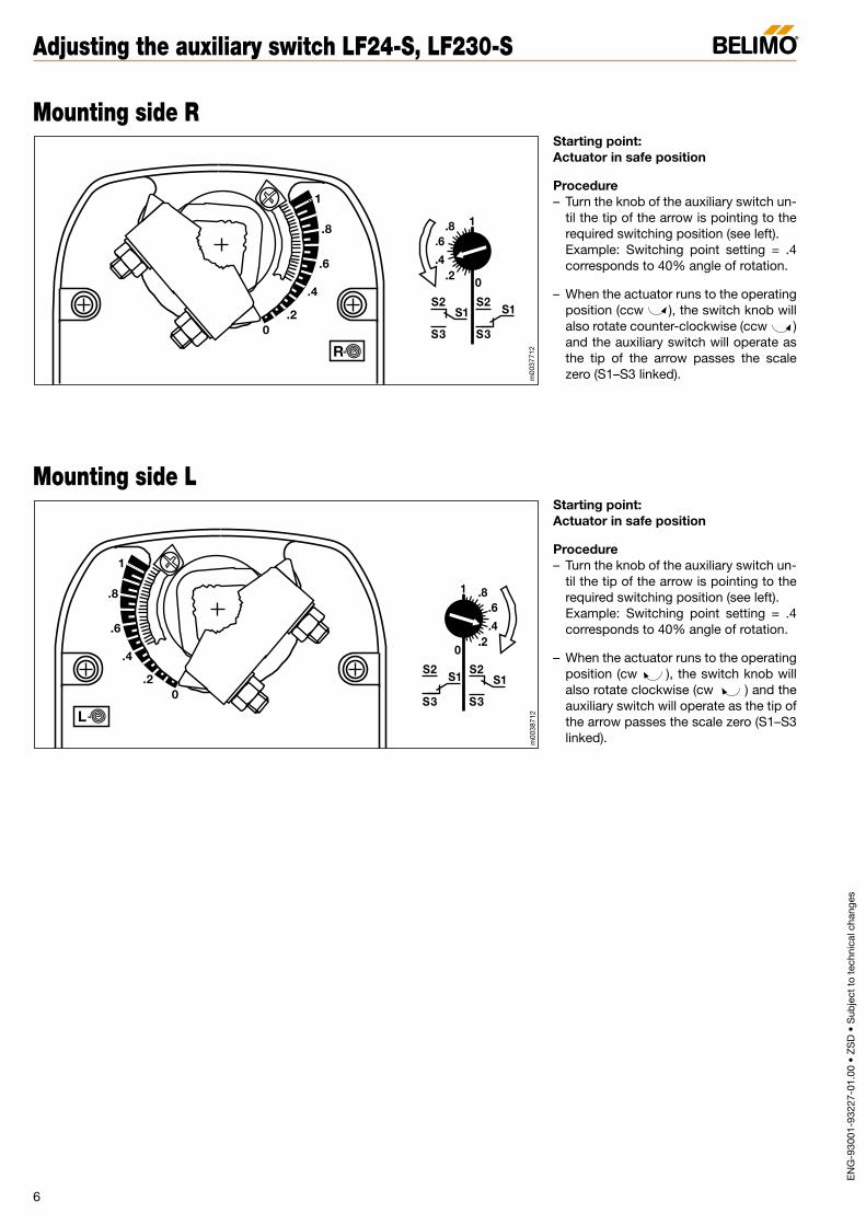
Starting point: Actuator in safe position
Procedure– Turn the knob of the auxiliary switch un-
til the tip of the arrow is pointing to therequired switching position (see left).Example: Switching point setting = .4corresponds to 40% angle of rotation.
– When the actuator runs to the operatingposition (ccw ), the switch knob willalso rotate counter-clockwise (ccw )and the auxiliary switch will operate asthe tip of the arrow passes the scale zero (S1–S3 linked).
Starting point: Actuator in safe position
Procedure– Turn the knob of the auxiliary switch un-
til the tip of the arrow is pointing to therequired switching position (see left).Example: Switching point setting = .4corresponds to 40% angle of rotation.
– When the actuator runs to the operatingposition (cw ), the switch knob willalso rotate clockwise (cw ) and theauxiliary switch will operate as the tip ofthe arrow passes the scale zero (S1–S3linked).
6
Adjusting the auxiliary switch LF24-S, LF230-S
Mounting side R
Mounting side L
m00
3771
2m
0038
712
BC

EN
G-9
3001
-932
27-0
1.00
• Z
SD
• S
ubje
ct t
o te
chni
cal c
hang
es
Nominal voltage range AC 19.2...28.8 V, DC 21.6...28.8 VNominal voltage AC 24 V 50/60 Hz, DC 24 V
Power consumption– motoring 2.5 W– holding 1 WConnecting cable 1 m long, 4 x 0.75 mm2
Technical data LF24-3
LF24-3
g g
Parallel connection of several actuators ispossible. Power consumption must be observed.
Connect via safetyisolating transformer!
T ~
AC 24 V- + DC 24 V
Y
1 2 3 4
1 Y2T ~
- +
a b
L0
.2
.4
.6
.8
1
R0
.2
.4
.6
.8
1
stop stop stop stop
a b(Y1) (Y2) R L R L
Reversing switch
Mounting side
Position indication mechanicalProtection class (safety extra-low voltage)
Maintenance maintenance-freeWeight 1400 g
Degree of protection IP 54
EMC CE according to 89/336/EEC, 92/31/EEC, 93/68/EEC
Ambient temp. range –30...+50 °CNon-operating temp. –40...+80 °CHumidity test to EN 60335-1
Torque – motor min. 4 Nm (at rated voltage)– spring return min. 4 Nm
Direction of rotation – motor selected with switch L/R– spring return selected by L/R mounting
Input resistanceControl inputs Y1, Y2 1000 Ω (0.6 W)
Angle of rotation max. 95° (adjustable 37...100% with built-in mechanical stop)
Running time – motor 150 s – spring return ≈ 20 s @ –20...50 °C / max. 60 s @ –30 °C
Sound power level motor max. 30 dB (A), spring ≈ 62 dB (A)
Service life min. 60 000 operations
For wire sizing 5 VA (Imax 5.8 A @ 5 ms)
ApplicationFor the operation of air dampers thatperform safety functions (e.g. frost andsmoke protection, hygiene, etc.).
Mode of operationThe LF24-3 is controlled by a 3-point sig-nal. The actuator runs to the position spe-cified by the control signal while tensioningthe return spring at the same time. If thepower supply is interrupted, the energystored in the spring moves the damperback to its safe position.
Product features
Simple direct mounting on the damperspindle by universal spindle clamp. An anti-rotation device is supplied to prevent un-wanted rotation of the whole unit.
Mechanical angle of rotation limiting ad-justable with built-in stop.
High functional reliability The actuator is overload proof, needs nolimit switches and halts automatically atthe end stop.
Examples of control modes, page 8
Mounting accessories, page 11
Mounting instructions, pages 13...15
Important: Read the notes about the useand torque requirements of the damperactuators on page 3.
Dampers up to approx. 0.8 m2
Modulating actuator (AC/DC 24 V)
3-point control
Dimensions
7
LF24-3 Spring return actuator 4 Nm
Wiring diagram
w01
1271
2p
0052
712
0.2
.4
.6.8
1
155
9318
98
82 5718
.56.
580
6.512.625
125
8...16
181
d00
3371
2
BC
III
EN
G-9
3001
-932
27-0
1.00
• Z
SD
• S
ubje
ct t
o te
chni
cal c
hang
es
L0
.2
.4
.6
.8
1
R0
.2
.4
.6
.8
1
LF24-3
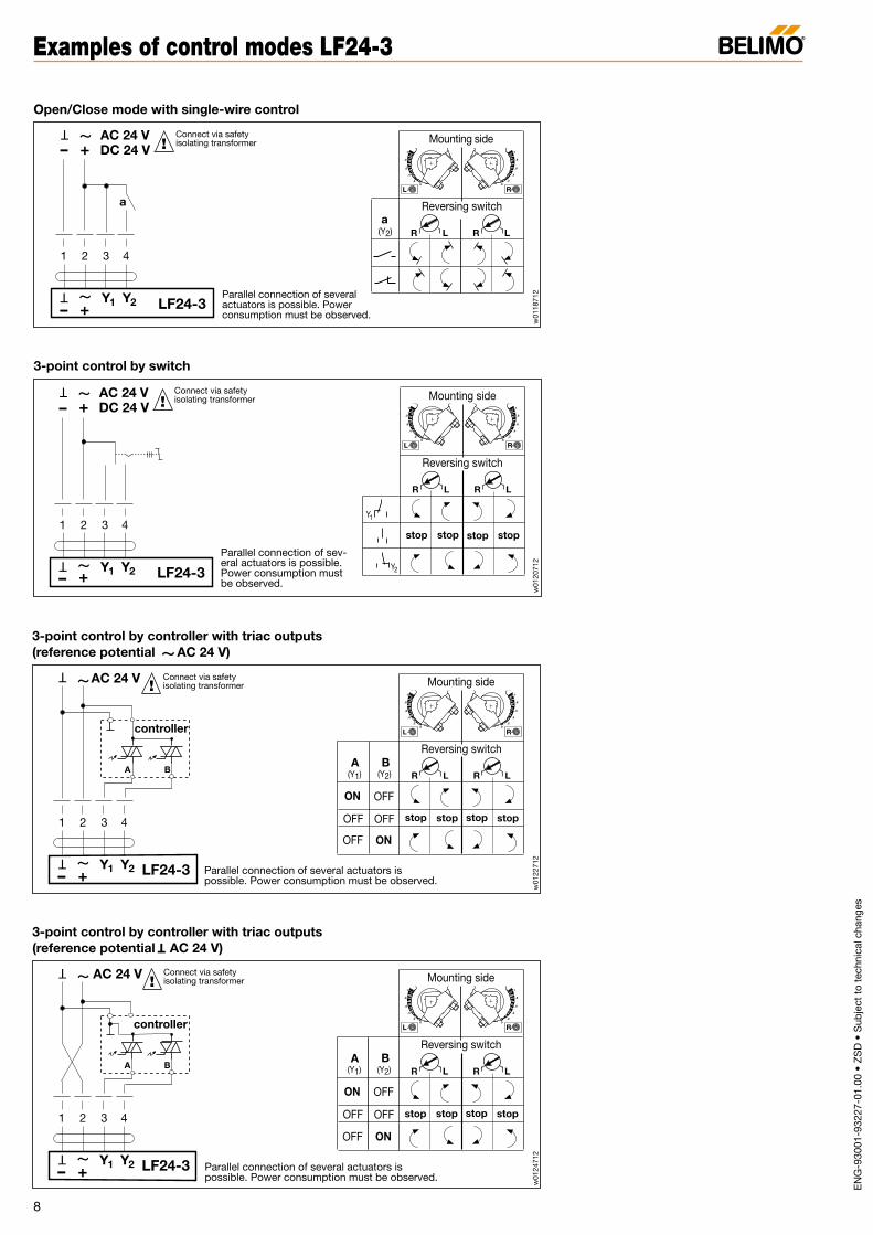
Open/Close mode with single-wire control
Parallel connection of severalactuators is possible. Powerconsumption must be observed.
!
T ~
AC 24 V- + DC 24 V
Y
1 2 3 4
1 Y2
T ~
- +
a
a(Y2)
Connect via safetyisolating transformer
R L R L
Reversing switch
Mounting side
L0
.2
.4
.6
.8
1
R0
.2
.4
.6
.8
1
LF24-3
3-point control by switch
Parallel connection of sev-eral actuators is possible.Power consumption mustbe observed.
Connect via safetyisolating transformer!
T ~
AC 24 V- + DC 24 V
Y
1 2 3 4
1 Y2
T ~
- +
stop stop stop stop
Y2
R L R L
Reversing switch
Y1
Mounting side
Parallel connection of several actuators ispossible. Power consumption must be observed.
!
T ~AC 24 V
- LF24-3Y
1 2 3 4
1 Y2
T ~
+
A B
3-point control by controller with triac outputs(reference potential AC 24 V)
controller
Connect via safetyisolating transformer
~
L0
.2
.4
.6
.8
1
R0
.2
.4
.6
.8
1
A B(Y1) (Y2)
ON
OFF
OFF
OFF
OFF ON
stop stop stop stop
R L R L
Reversing switch
Mounting side
3-point control by controller with triac outputs(reference potential AC 24 V)
T
Parallel connection of several actuators ispossible. Power consumption must be observed.
!
T ~AC 24 V
- LF24-3Y
1 2 3 4
1 Y2
T ~
+
A
controller
B
Connect via safetyisolating transformer
L0
.2
.4
.6
.8
1
R0
.2
.4
.6
.8
1
A B(Y1) (Y2)
ON
OFF
OFF
OFF
OFF ON
stop stop stop stop
R L R L
Reversing switch
Mounting side
8
Examples of control modes LF24-3
w01
2071
2w
0118
712
w01
2271
2w
0124
712
BC

0.2
.4
.6.8
1
155
9318
98
82 5718
.56.
580
6.512.625
125
8...16
181
EN
G-9
3001
-932
27-0
1.00
• Z
SD
• S
ubje
ct t
o te
chni
cal c
hang
es
Nominal voltage range AC 19.2...28.8 V, DC 21.6...28.8 V
Nominal voltage AC 24 V 50/60 Hz, DC 24 V
Power consumption 2.5 W motoring, 1 W at restConnecting cable 1 m long, 4 x 0.75 mm2
Technical data LF24-SR
L0
.2
.4
.6
.8
1
R0
.2
.4
.6
.8
1
Y DC 0...10 V
U DC 2...10 V Measuring voltage U for position indicating oras master-slave control signal
Y
1 2 3
LF24-SR
Parallel connection of several actuatorsis possible. Power consumption mustbe observed.
5
U
T ~
AC 24 V- + DC 24 V
T ~- +
Connect viasafety isolatingtransformer!
Controllers by: ABB, AEG, Bälz, Centra, Controlli,C.S.I., Danfoss, DIGI'Control, Elesta, GA, H.C.System,Honeywell, Inel, IWK, Johnson, Kieback & Peter,Landis&Staefa, Messner, Priva, RAM, R+S, Samson,Satchwell, Sauter, SE-Electronic, Siemens, TA, Trend.
withY = 0
withY = 0
withY = 0
withY = 0
R L
Reversing switch
R L
Mounting side
Position indication mechanicalProtection class (safety extra-low voltage)
Maintenance maintenance-freeWeight 1400 g
Degree of protection IP 54
EMC CE according to 89/336/EEC, 92/31/EEC, 93/68/EEC
Ambient temp. range –30...+50 °CNon-operating temp. –40...+80 °CHumidity test to EN 60335-1
Torque – motor min. 4 Nm (at rated voltage)– spring return min. 4 Nm
Direction of rotation – motor selected with switch L/R– spring return selected by L/R mounting
Control signal Y DC 0...10 V @ 100 kΩ input resistanceOperating range DC 2...10 V for 0...100%
Measuring voltage U DC 2...10 V (max. 0.7 mA) for 0....100%
Angle of rotation max. 95° (adjustable 37...100% with built-in mechanical stop)
Running time – motor 150 s – spring return ≈ 20 s @ –20...50 °C / max. 60 s @ –30 °C
Sound power level motor max. 30 dB (A), spring ≈ 62 dB (A)
Service life min. 60 000 operations
For wire sizing 5 VA (Imax 5.8 A @ 5 ms)
ApplicationFor the operation of air dampers thatperform safety functions (e.g. frost andsmoke protection, hygiene, etc.).
Mode of operationThe LF24-SR is controlled by a standardDC 0...10 V signal. The actuator runs to theposition specified by the control signalwhile tensioning the return spring at thesame time. If the power supply is interrupt-ed, the energy stored in the spring movesthe damper back to its safe position.
Product featuresSimple direct mounting on the damperspindle by universal spindle clamp. An anti-rotation device is supplied to prevent un-wanted rotation of the whole unit.
Mechanical angle of rotation limiting ad-justable with built-in stop.
High functional reliability The actuator is overload proof, needs nolimit switches and halts automatically atthe end stop.
Electrical accessories (see Doc. 2. Z-1)SG..24 PositionersZAD24 Digital position indicator
Control/monitoring functions, page 10
Mounting accessories, page 11
Mounting instructions, pages 13...15
Important: Read the notes about the useand torque requirements of the damperactuators on page 3.
Dampers up to approx. 0.8 m2
Modulating actuator (AC/DC 24 V)
Control DC 0...10 V and positionfeedback DC 2...10 V
Dimensions
9
LF24-SR Spring return actuator 4 Nm
Wiring diagram
w01
1471
2p
0053
712
d00
3371
2
BC
III

EN
G-9
3001
-932
27-0
1.00
• Z
SD
• S
ubje
ct t
o te
chni
cal c
hang
es
L0
.2
.4
.6
.8
1
R0
.2
.4
.6
.8
1T ~
Function monitoring
AC 24 V
1 2 3
T ~
Remote control 0...100%
1 2 3SGA24, SGF24SGE24
Positioner4
Y
T ~
Z
LF24-SR
Parallel connection of furtheractuators is possible (up to 10).
T ~
1 2 3SGA24, SGF24SGE24
Positioner4
Y
T ~
Z
Parallel connection of furtheractuators is possible (up to 10).
Minimum position
Y DC 0...10 V (from controller)
100%Angle of rotation
0%
Y [ V ]
10 V
min.
0 V
AC 24 VAC 24 V Connect via safetyisolating transformer!
Connect via safetyisolating transformer!
Connect via safetyisolating transformer!
Y U
T ~
- +
5 1 2 3 5
LF24-SRY U
T ~
- +
Control by 4...20 mA via external resistor
Procedure• AC 24 V at terminals 1 and 2• Disconnect terminal 3: – For direction of rotation "L": actuator runs – For direction of rotation "R": actuator runs• link terminals 2 and 3: actuator runs in the opposite direction
LF24-SRY U
T ~
- +
1 2 3 5
T ~
Position indication and / or master-slave control (depending on position)
AC 24 V Position indication
LF24-SR
to next actuator
Slave actuator
Connect viasafety isolatingtransformer
!
Y U
T ~
- +
1 2 3 5
Note ± 5%synchronism tolerancebetween actuators
Master-slave control
LF24-SRMaster actuatorY U
T ~
- +
1 2 3 5
Override control
LF24-SR
Parallel connection of several actuators ispossible. Power consumption must be observed.
ab 4...20 mA
U DC 2...10 V
Y
1 2 3
LF24-SR
5
U
T
AC 24 V- + DC 24 V
T ~
- +
Connect viasafety isolatingtransformer
~
(-)(+)500 Ω
*
*The 500 Ω resistor converts the4...20 mA current signal to avoltage signal of DC 2...10 V.
!
T
AC 24 V- + DC 24 V
~
Connect viasafety isolatingtransformer!
Y UT ~
- +
1 2 3 5
L0
.2
.4
.6
.8
1
R0
.2
.4
.6
.8
1
a b
Control mode
R L R L
Reversing switch
Mounting side
Y DC 0...10 V
Y DC 0...10 V
10
Control and monitoring functions LF24-SR
w01
1671
2
BC

ZG-LF3Damper linkage kit for side mounting(with 2 ball joints KG8)
EN
G-9
3001
-932
27-0
1.00
• Z
SD
• S
ubje
ct t
o te
chni
cal c
hang
es
11
Mounting accessories LF...
K6-1Spindle clampSuitable for damper spindles 16...20 mmdiameter.
The spindle clamp is secured to the ac-tuator by means of a circlip.
K6-1
16...20
KH-LFCrank arm with slot width 8.2 mmSuitable for damper spindles 8...16 mmdiameter.
The crank arm is secured to the actuatorby means of a circlip.
KH-LF (Application example see page 14)
8...16
KH-LF1Crank arm with slot width 8.2 mmSuitable for damper spindles 16...20 mmdiameter.
The crank arm is secured to the actuatorby means of a circlip.
16...20
ZG-LF3 (Application example see page 14, fig. 2)
ZDB-LFAngle of rotation limiting and pointer
The pointer is secured to the actuator bymeans of a circlip.
ZDB-LF (Application example see page 13)
ZG-LF1Damper linkage kit for flat mounting(with 2 ball joints KG8)
ZG-LF1 (Application example see page 14, fig. 1)
ZG-LF2Damper linkage kit for flat mounting(without ball joints KG8)
m00
3971
2m
0040
712
m00
4171
2m
0042
712
m00
4371
2BC

m00
6380
3
AV10-18
240
KG8
KG10
KH8
EN
G-9
3001
-932
27-0
1.00
• Z
SD
• S
ubje
ct t
o te
chni
cal c
hang
es
12
General mounting accessories
KH8Universal crank armZinc-plated steel; suitable for damperspindles Ø 10...18 mm or
10...14 mm, slot width 8.2 mm.
KG8Ball jointZinc-plated steel; suitable for use with KH8universal crank arms and round steel rodØ 8 mm.
KG10Ball jointZinc-plated steel; suitable for use with KH8universal crank arm and round steel rod Ø 10 mm.
AV10-18Universal spindle extensionSuitable for damper spindles 10...18 mmdiameter.
If an AV10-18 is to be used in conjunctionwith an LF..., the actuator must be fittedwith a K6-1 spindle clamp.
10...18
m00
1671
2m
0018
707
m00
4571
2
m00
2070
7
1840
max
. ø 1
8
10096
≈90≈30
8.2
8
39
40
8
10
60
8m
0064
803
m00
1780
5m
0044
806
BC

Made i
n Swit
zerlan
dL
1
.6
.8
.4
.20
L
Made i
n Swit
zerlan
dL
1
.6
.8
.4
.20
L
ZDB-LF
Made i
n Swit
zerlan
d
1
.8
.6
.4
.2
0
R
R
ZDB-LF
Made i
n Swit
zerlan
dL
1
.6
.8
.4
.20
37...100%
Made i
n Swit
zerlan
dL
1
.6
.8
.4
.20
37...100%
ZDB-LF
min. 20
8...16
Made i
n Swit
zerlan
d
1
.8
.6
.4
.2
0
R
R
min. 84
8...16
EN
G-9
3001
-932
27-0
1.00
• Z
SD
• S
ubje
ct t
o te
chni
cal c
hang
es
13
Instructions for direct mounting
m00
4671
2
BC

Made in
L
1
.6
.8
.4
.20
1
1
4
3
5
5
6
Made in
L
1
.6
.8
.4
.20
Made in
L
1
.6
.8
.4.2
0
Made in
L
1
.6
.8
.4
.20
2
4
5
32
2
EN
G-9
3001
-932
27-0
1.00
• Z
SD
• S
ubje
ct t
o te
chni
cal c
hang
es
14
Instructions for mounting with linkage (ZG-LF… kit)
Flat mounting (fig. 1)
Kit specification ZG-LF11 mounting bracket LF1 crank arm 1⁄2”1 circlip LF2 ball joints KG8
3 screws M6 x 673 nuts M63 self-tapping screws 4.2 x 13
Universal crank arm:order separately, not included with theZG-LF... mounting accessory.
➀➂➃➄
➅
Side mounting (fig. 2)
Kit specification ZG-LF32 mounting brackets LF1 crank arm 1⁄2”1 circlip LF2 ball joints KG8
2 screws M6 x 672 nuts M64 self-tapping screws 4.2 x 13
➁➂➃➄
m00
4771
2m
0048
712
BC

Made in SwitzlandR
0
.2
.4
.6
.8
1
Made in Switzland
R
0
.2
.4
.6
.8
1
a
c
d
b
e
EN
G-9
3001
-932
27-0
1.00
• Z
SD
• S
ubje
ct t
o te
chni
cal c
hang
es
15
Mounting instruction for tight-sealing dampers
1. Move damper blades to the fail-safeposition (a) and determine the orienta-tion of the universal clamp.
2. Engage the actuator on the shaft asclose as possible to the determined ori-entation. Fix the screws lightly on theV-bracket by hand. In the example thespring return has to go clockwise (cw).Therefore the actuator has to be visiblewith the mounting side R.
3. Mount the universal mounting bracketin the right position (do not tighten thescrews).
4. Remove the screw at one end of themounting bracket and pivot it awayfrom the actuator (b).
5. Loosen the universal clamp and, mak-ing sure not to move the damper shaft,rotate the actuator approximatively 5°in the direction which would open thedamper (c).
6. Tighten the universal clamp to the shaft(10 mm wrench).
7. Rotate the actuator “damper closed”to apply pressure to the damper seals(d).
8. Rotate the mounting bracket in thedefinitive position (e) and tighten all fas-teners.
Installation steps as example
m00
4971
2
BC