Product Guideline Filter Drier Application and Service ... · Filter Drier Application and Service...
12
abc REFRIGERATION AND AIR CONDITIONING Filter Drier Application and Service Guideline Product Guideline Refrigeration & Air Conditioning Controls
Transcript of Product Guideline Filter Drier Application and Service ... · Filter Drier Application and Service...

abc
R E F R I G E R A T I O N A N D A I R C O N D I T I O N I N G
Filter Drier Application and Service Guideline
Product Guideline
Refrigeration & Air Conditioning Controls
abc
2 U1.R7.0G.12 © Danfoss Limited (GBSCL) 03.2003
Filter Drier Application and Service Guideline
Filter driers are one of the most important components in a refrigeration or air conditioning system for several reasons. In this article we shall examine the factors behind their construction and application, and relate them to the range available from Danfoss, past & present. Firstly we will look at the current range of DCL & DML filter driers available from Danfoss, and compare them to the now obsolete DN & DU range.
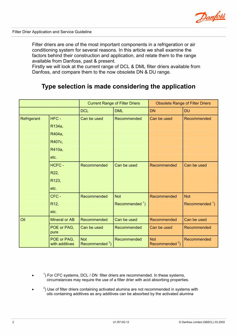
Type selection is made considering the application
Current Range of Filter Driers Obsolete Range of Filter Driers
DCL DML DN DU
Refrigerant HFC - Can be used Recommended Can be used Recommended
R134a,
R404a,
R407c,
R410a,
etc.
HCFC - Recommended Can be used Recommended Can be used
R22,
R123,
etc.
CFC - Recommended Not Recommended Not
R12, Recommended 1) Recommended 1)
etc.
Oil Mineral or AB Recommended Can be used Recommended Can be used
POE or PAG, pure
Can be used Recommended Can be used Recommended
POE or PAG, with additives
Not Recommended 2)
Recommended Not Recommended 2)
Recommended
• 1) For CFC systems, DCL / DN filter driers are recommended. In these systems, circumstances may require the use of a filter drier with acid absorbing properties.
• 2) Use of filter driers containing activated alumina are not recommended in systems with oils containing additives as any additives can be absorbed by the activated alumina

abc
3 © Danfoss Limited (GBSCL) 03.2003
Filter Drier Application and Service guideline
Features
Current Range of Filter Driers
DCL DML The Filter Drier Shell
80% 3Å molecular sieves with 20% activated alumina.
100% 3Å molecular sieves core. UL approved for MWP up to 42 Bar.
Available with solder & flare connections.
Perfect core blend for systems that operate at high condensing temperatures and require high drying capacity.
High drying capacity minimising the risk of acid formation (hydrolysis).
Corrosion resistant powder-painted finish suitable for all environments, including marine.
Optimised for CFC & HFC refrigerants (R22, R502, etc.) with mineral or alkyl benzene oils. Compatible with HFC’s & refrigerant blends.
Optimised for HFC refrigerants (R134a, R404a, R410A, etc.) with POE or PAG oils. Compatible with R22.
Allows installation in any orientation, providing the arrow is in the direction of flow. Available in sizes from 3 to 75 cubic inches.
Will not deplete oil additives.
U1.R7.0G.12

abc
4 © Danfoss Limited (GBSCL) 03.2003
Filter Drier Application and Service Guideline
Features
Obsolete Range of Filter Driers
DN DU The Filter Drier Shell
80% 3Å molecular sieves with 20% activated alumina.
100% 3Å molecular sieves core. MWP up to 35 Bar.
Was available with solder & flare connections.
Perfect core blend for systems that operate at high condensing temperatures and require high drying capacity.
High drying capacity minimising the risk of acid formation (hydrolysis).
Corrosion resistant powder-painted finish suitable for all environments, including marine.
Optimised for CFC & HFC refrigerants (R22, R502, etc.) with mineral or alkyl benzene oils. Compatible with HFC’s & refrigerant blends.
Optimised for HFC refrigerants (R134a, R404a, R410A, etc.) with POE or PAG oils. Compatible with R22.
Allows installation in any orientation, providing the arrow is in the direction of flow.
Will not deplete oil additives.
U1.R7.0G.12
abc
5 © Danfoss Limited (GBSCL) 03.2003
Filter Drier Application and Service Guideline
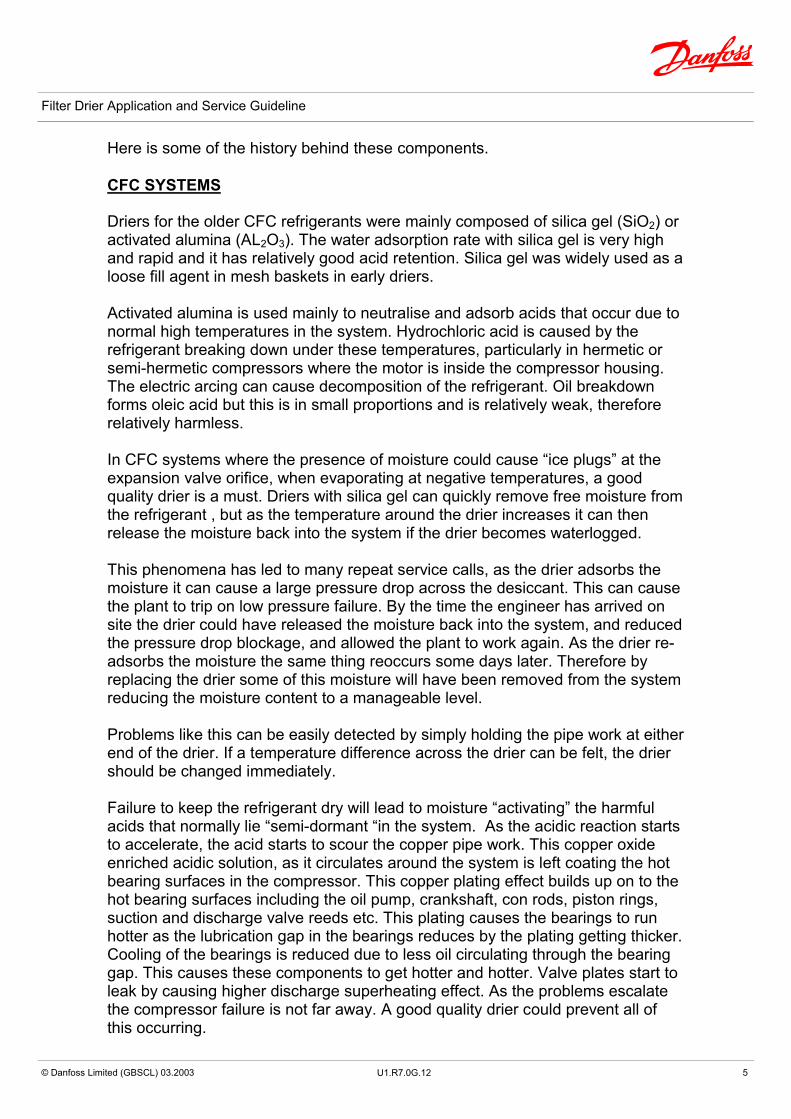
Here is some of the history behind these components. CFC SYSTEMS Driers for the older CFC refrigerants were mainly composed of silica gel (SiO2) or activated alumina (AL2O3). The water adsorption rate with silica gel is very high and rapid and it has relatively good acid retention. Silica gel was widely used as a loose fill agent in mesh baskets in early driers. Activated alumina is used mainly to neutralise and adsorb acids that occur due to normal high temperatures in the system. Hydrochloric acid is caused by the refrigerant breaking down under these temperatures, particularly in hermetic or semi-hermetic compressors where the motor is inside the compressor housing. The electric arcing can cause decomposition of the refrigerant. Oil breakdown forms oleic acid but this is in small proportions and is relatively weak, therefore relatively harmless. In CFC systems where the presence of moisture could cause “ice plugs” at the expansion valve orifice, when evaporating at negative temperatures, a good quality drier is a must. Driers with silica gel can quickly remove free moisture from the refrigerant , but as the temperature around the drier increases it can then release the moisture back into the system if the drier becomes waterlogged. This phenomena has led to many repeat service calls, as the drier adsorbs the moisture it can cause a large pressure drop across the desiccant. This can cause the plant to trip on low pressure failure. By the time the engineer has arrived on site the drier could have released the moisture back into the system, and reduced the pressure drop blockage, and allowed the plant to work again. As the drier re-adsorbs the moisture the same thing reoccurs some days later. Therefore by replacing the drier some of this moisture will have been removed from the system reducing the moisture content to a manageable level. Problems like this can be easily detected by simply holding the pipe work at either end of the drier. If a temperature difference across the drier can be felt, the drier should be changed immediately. Failure to keep the refrigerant dry will lead to moisture “activating” the harmful acids that normally lie “semi-dormant “in the system. As the acidic reaction starts to accelerate, the acid starts to scour the copper pipe work. This copper oxide enriched acidic solution, as it circulates around the system is left coating the hot bearing surfaces in the compressor. This copper plating effect builds up on to the hot bearing surfaces including the oil pump, crankshaft, con rods, piston rings, suction and discharge valve reeds etc. This plating causes the bearings to run hotter as the lubrication gap in the bearings reduces by the plating getting thicker. Cooling of the bearings is reduced due to less oil circulating through the bearing gap. This causes these components to get hotter and hotter. Valve plates start to leak by causing higher discharge superheating effect. As the problems escalate the compressor failure is not far away. A good quality drier could prevent all of this occurring.
U1.R7.0G.12

abc
6 © Danfoss Limited (GBSCL) 03.2003
Filter Drier Application and Service Guideline
Some types of driers, if allowed to become too heavily contaminated, and are left to operate over long periods in that condition, have been known to start to de-compose and eventually break down. From Danfoss the DN drier provided the ideal solution for HCFC‘s and for the “Drop In’s” as its core is made up from both molecular sieve and activated alumina. This gives several advantages in that it has a high moisture adsorption capacity with a high moisture retention ability, plus a good acid adsorption capacity plus extremely high levels of debris filtration to give a good overall degree of safety to the plant. Note it is now illegal to carry out work on CFC system’s. FILTRATION Filter Driers not only dry the refrigerant they also act as an extremely good particle filter down to as low as 20 micron. HFC SYSTEMS In HFC systems the primary reason for a drier is to remove moisture from the system. During system build up the polyolester oils (POE) or the polyalcylene glycol (PAG) lubricants which are highly hydroscopic, can carry substantial amounts of free water. If this free moisture content in the system is not brought down to the required level, the corrosive and decomposing properties of the water will be activated. Acid that is generated by high friction temperatures and by the lubricant / refrigerant mixture will become aggressive. This acid then can start to attack the metal parts which start to corrode, and also starts to break down the motor insulation material, where this can lead to arcing, spot burns and then a complete motor burnout. Therefore the choice of drier for new HFC/POE systems should be a drier which has the following properties.
Fast reaction rate Good filtration properties Compatibility with HFC refrigerants & POE oils that contain special additives to enhance their lubrication qualities Some of the lubricant additives used are :- Antioxidants Viscosity enhancers Viscosity /pressure Viscosity / temperature corrosion inhibitors Wearing property enhancers Anti foaming agents
When selecting a drier for these combinations it is necessary to select driers that neither absorb nor chemically react with these additives.
U1.R7.0G.12
abc
7 © Danfoss Limited (GBSCL) 03.2003
Filter Drier Application and Service Guideline
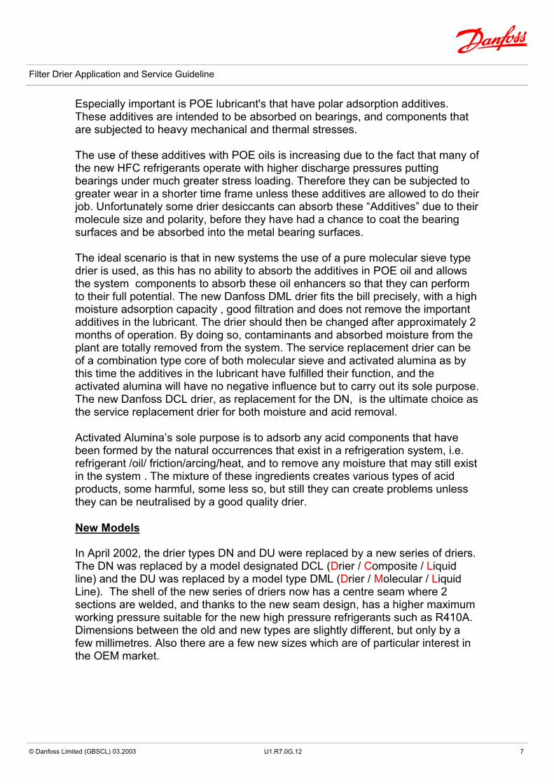
Especially important is POE lubricant's that have polar adsorption additives. These additives are intended to be absorbed on bearings, and components that are subjected to heavy mechanical and thermal stresses. The use of these additives with POE oils is increasing due to the fact that many of the new HFC refrigerants operate with higher discharge pressures putting bearings under much greater stress loading. Therefore they can be subjected to greater wear in a shorter time frame unless these additives are allowed to do their job. Unfortunately some drier desiccants can absorb these “Additives” due to their molecule size and polarity, before they have had a chance to coat the bearing surfaces and be absorbed into the metal bearing surfaces. The ideal scenario is that in new systems the use of a pure molecular sieve type drier is used, as this has no ability to absorb the additives in POE oil and allows the system components to absorb these oil enhancers so that they can perform to their full potential. The new Danfoss DML drier fits the bill precisely, with a high moisture adsorption capacity , good filtration and does not remove the important additives in the lubricant. The drier should then be changed after approximately 2 months of operation. By doing so, contaminants and absorbed moisture from the plant are totally removed from the system. The service replacement drier can be of a combination type core of both molecular sieve and activated alumina as by this time the additives in the lubricant have fulfilled their function, and the activated alumina will have no negative influence but to carry out its sole purpose. The new Danfoss DCL drier, as replacement for the DN, is the ultimate choice as the service replacement drier for both moisture and acid removal. Activated Alumina’s sole purpose is to adsorb any acid components that have been formed by the natural occurrences that exist in a refrigeration system, i.e. refrigerant /oil/ friction/arcing/heat, and to remove any moisture that may still exist in the system . The mixture of these ingredients creates various types of acid products, some harmful, some less so, but still they can create problems unless they can be neutralised by a good quality drier. New Models In April 2002, the drier types DN and DU were replaced by a new series of driers. The DN was replaced by a model designated DCL (Drier / Composite / Liquid line) and the DU was replaced by a model type DML (Drier / Molecular / Liquid Line). The shell of the new series of driers now has a centre seam where 2 sections are welded, and thanks to the new seam design, has a higher maximum working pressure suitable for the new high pressure refrigerants such as R410A. Dimensions between the old and new types are slightly different, but only by a few millimetres. Also there are a few new sizes which are of particular interest in the OEM market.
U1.R7.0G.12

abc
8 xxxxxxxx © Danfoss Limited (GBSCL) 03.2003
Filter Drier Application and Service Guideline
Retrofitting When retrofitting from CFC’s to HFC’s, care should be taken to protect the compressor from old system debris that could be brought back to the compressor from the evaporator. POE oils with HFC refrigerants have a cleansing action that can break down congealed oil that have laid dormant in the evaporator, and scour pipe work scale brazing debris and the like. In these situations both liquid line and suction line filter driers must be used. Failure to do this can lead to the oil in the compressor sump being contaminated with a greasy slime, that can block oil filters and cause bearing failure or oil pressure failures. It may be necessary to change driers and oil charges several times before the system can function correctly. New Plant Installations It is very important during installation of any new HFC systems that during pipe work brazing an inert gas such as “White Spot” Nitrogen is used to purge oxygen from the pipe work. Copper oxides, brazing debris, dust dirt etc that are left over, will be cleaned from the internal pipe work by the refrigerant /oil mixture which has a great scouring ability. Failure to carry out this operation will lead to these contaminants being scoured from the pipe work wall, and then carried back to the compressor. This debris then mixes with the oil and turns into a fine grinding paste substance which degrades the lubricant and can lead to excessive wear to the compressor motion wear in a very short time. This wear can reduce the compressors swept volume drastically. NH3 Systems The new Danfoss DM drier core can be used with the DCR shell in Ammonia systems where its filtration properties can remove fine ferrous particles and welding debris that cause many valve failures in these systems. It can also remove moisture if the Ammonia becomes too moisture rich, which can lead to scouring of the pipe work and subsequent plant failure although this is an extremely slow process. It can be used to advantage in the pump discharge of low temperature flooded systems, where the low side may operate under a vacuum and the risk of moisture and corrosion to evaporators and control valves may be a problem. Special gaskets are available for use with NH3. Burn Outs The Danfoss - DAS burn out drier is designed to remove or neutralise acids that are present after a burn out. These acids if not prevented from entering the new replacement compressor will attack the insulation of the new compressor’s motor and can quickly cause a further burn out. By fitting a DML drier in the liquid line and a DAS drier in the suction line the system will be quickly cleaned up. The DML drier will quickly adsorb any moisture and the DAS will remove any acid products. The DML drier by adsorbing the moisture content will help neutralise any acid in the system. Water acts as the catalyst for acid to become aggressive, so no water ,and no problem. The DAS core is made up of 70% Activated alumina and 30 % Molecular sieve.

abc
9 © Danfoss Limited (GBSCL) 03.2003
Filter Drier Application and Service Guideline
Bi Flow Driers The Danfoss range of Bi Flow driers designated DB/DBU’s have been replaced with types DMB, and type DCB. Both driers incorporate check valves so that particles that are collected in the desiccant are not released back into the system when the flow is reversed, and both have a higher maximum working pressure of 42Bar. The DCB drier has a composite core of activated alumina and molecular sieve, ideal for HCFC and Drop In refrigerants and the DMB has a 100% molecular sieve using 3Å desiccant used predominantly for HFC systems. These driers are used in reverse cycle heat pumps systems. Large Removable Core Driers In the range of driers comes the DCR removable core type. The shells come in sizes 1,2,3,or 4 core depending on the capacity requirements. Solder and weld connections from 5/8” up to 2-1/8 " sizes are available. A new range of cores for the DCR include the 48 -DA, -DM, -DC and 48-F. The DA core is 70% activated Alumina with 30% Molecular sieve, for the removal of acids after a compressor burn out. The DCR shell with the DA cores are mounted in the suction line just before the compressor to remove any acid trying to get back into the new machine . The DM is a pure molecular sieve core ideal for HFC / Polyolester lubricant systems. This core has a large moisture adsorbing capacity. Particularly suited to new plants where there will be no acids present. This DCR plus DM core combination is also used in NH3 systems for removing dirt, sludge moisture, etc. This combination as been tried and tested on several ammonia systems which have been contaminated with a moisture saturated sludgy oil compound with excellent results. The DC core is the composite version core of 30% activated alumina & 70% molecular sieve .This core is the ideal solution for HCFC systems and for the drop in refrigerants. This core is also the main service replacement core for all systems as it is moisture and acid adsorbent, and covers all service requirements. The 48-F filter element is also ideal as a suction or liquid line filter for HCFC /HFC systems to clean up new or old dirty systems as it filters down to as low as 15 microns. This is ideal especially when steel pipe work is used where scale and welding slag can devastate a compressors motion work. Many engineers treat driers as a consumable component, but choosing the correct type for the system may be the difference between a good trouble free installation, and an expensive plant failure.
U1.R7.0G.12

abc
10 xxxxxxxx © Danfoss Limited (GBSCL) 03.2003
Filter Drier Application and Service Guideline
Sizing Driers Factory built systems are easier to select for, as normally the system charge quantity is calculated during design and the drier selected against refrigerant weight. Factory built units also normally have the advantage of having a cleaner build up, and undergoing a full evacuation process to dry out the system to a greater extent than a site built system, where it is far more difficult to control the cleanliness and dryness of the plant components. Therefore it is normally possible to use a smaller drier on a factory built unit providing the drier is changed after approximately six weeks of operation as the first drier will have adsorbed the moisture content of the refrigerant charge to almost the design point . The replacement drier will finish the job that the first one started. Site built plants do not have this advantage as typically the moisture content and the dirt content will be higher from day one and the drier has a lot more work to do. Drier selection is based on the ARI standard 710. Several expressions are used in the selection process such as the EPD (Equilibrium Point Dryness) This defines the lowest possible water content in a refrigerant in its liquid phase, after it has been through a drier. The drying capacity is the quantity of water the filter drier is able to adsorb at 24ºC and 52ºC liquid temperature. The selection is given in Kg of refrigerant being dried out. The start and finish figures in PPM vary with the refrigerant type. Selection can also be done against liquid capacity , condensing at 30ºC, evaporating at -15ºC with 0.07Bar ∆P. Driers come in solder, weld, and in the smaller sizes flare connections. Small factory systems tend to use solder driers as a total sealed system with a superior leak proof quality is desirable. Plants where regular service is carried out, normally employ either a flare connection or a removable core version, as un-brazing and re-brazing is an expensive option. Where possible flare driers using solder / flare adapters should be used as the flare adapter will give a stronger leak proof seal over the conventional pipe only flare. Pipe flares are banned in some countries as being weak and being the point of most gas leaks. Drier orientation is not too important but a downward flow is ideal as debris that is trapped in the drier will stay trapped. Driers fitted with a vertically upward flow cannot keep debris trapped, and when changing the drier loose debris can fall back into the system. The initial drier fitted to a new system should be deemed as the system commissioning / system clean up item. After some 6 to 8 weeks of operation this drier should be removed from the system and a replacement fitted. By carrying out this simple inexpensive operation, any entrained system debris and moisture

abc
11 © Danfoss Limited (GBSCL) 03.2003
Filter Drier Application and Service Guideline
will be permanently removed from the system, thereby removing the potential for problems later on. The replacement drier will now be at full capacity and able to give the plant a safety boost over its long working life. As it now has dry clean refrigerant flowing through it, it can dry and clean the system to an even greater degree thereby enhancing the operation of the plant. Whenever a system is opened up for service to be carried out a new drier should always be fitted. Loose fill driers should be rejected as the driers can end up with the desiccant flowing through the system blocking valves and orifices. Always fit a good quality solid core drier as it will do the best job. If a drier rattles ,throw it away and get a new one as you could be filling the plant with a gritty dusty substance which will slowly accumulate inside the compressor and cause excessive wear to all motion work.
So, get it right first time. It’s far cheaper in the long run.
U1.R7.0G.12
abc
abc
Danfoss can accept no responsibility for possible errors in catalogues, brochures and other printed material. Danfoss reserves the right to alter its products without notice. This also applies to products already on order provided that such alterations can be made without subsequent changes being necessary in specifications already agreed. All trademarks in this material are property of the respective companies. Danfoss and the Danfoss logotype are trademarks of Danfoss A/S. All rights reserved.
© Danfoss Limited (GBSCL) 03.2003
Filter Drier Application and Service Guideline
Website - www.danfoss.co.uk
Danfoss Limited Capswood Oxford Road Denham Bucks UB9 4LH Tel: 0870 241 7041 Fax: 0870 241 7045
U1.R7.0G.12