Amplitude Transmitter AMiribu.ac.ir/sitepics/gallery/229942228ch06.pdf · ∝: Modulation Index 0

S I G N A L S T H E B E S T
Product Guide
display
temperature
universal
i.s. interface
isolation
C O M M U N I C AT I O N F O U N D AT I O N
INMETRO
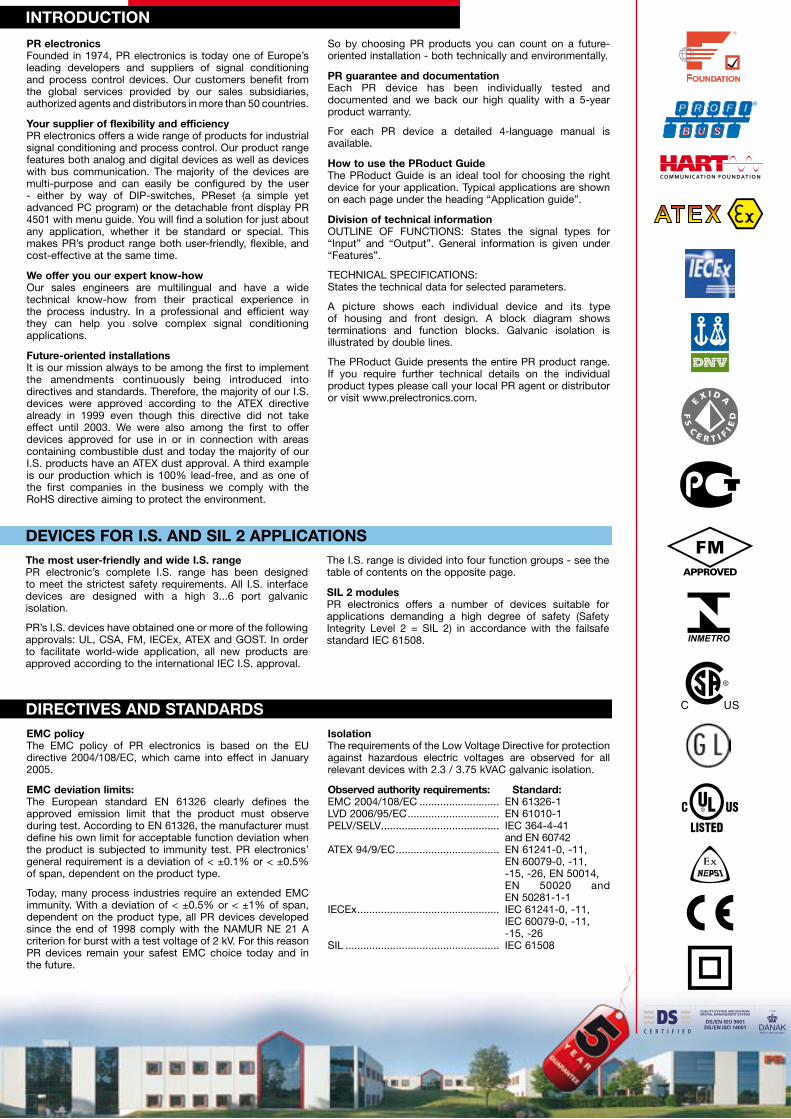
INTroduCTIoN
dIrECTIvES ANd STANdArdS
Pr electronics Founded in 1974, PR electronics is today one of Europe’s leading developers and suppliers of signal conditioning and process control devices. Our customers benefit from the global services provided by our sales subsidiaries, authorized agents and distributors in more than 50 countries.
Your supplier of flexibility and efficiencyPR electronics offers a wide range of products for industrial signal conditioning and process control. Our product range features both analog and digital devices as well as devices with bus communication. The majority of the devices are multi-purpose and can easily be configured by the user - either by way of DIP-switches, PReset (a simple yet advanced PC program) or the detachable front display PR 4501 with menu guide. You will find a solution for just about any application, whether it be standard or special. This makes PR’s product range both user-friendly, flexible, and cost-effective at the same time.
We offer you our expert know-howOur sales engineers are multilingual and have a wide technical know-how from their practical experience in the process industry. In a professional and efficient way they can help you solve complex signal conditioning applications.
Future-oriented installationsIt is our mission always to be among the first to implement the amendments continuously being introduced into directives and standards. Therefore, the majority of our I.S. devices were approved according to the ATEX directive already in 1999 even though this directive did not take effect until 2003. We were also among the first to offer devices approved for use in or in connection with areas containing combustible dust and today the majority of our I.S. products have an ATEX dust approval. A third example is our production which is 100% lead-free, and as one of the first companies in the business we comply with the RoHS directive aiming to protect the environment.
So by choosing PR products you can count on a future-oriented installation - both technically and environmentally.
Pr guarantee and documentationEach PR device has been individually tested and documented and we back our high quality with a 5-year product warranty.
For each PR device a detailed 4-language manual is available.
How to use the Product GuideThe PRoduct Guide is an ideal tool for choosing the right device for your application. Typical applications are shown on each page under the heading “Application guide”.
division of technical informationOUTLINE OF FUNCTIONS: States the signal types for “Input” and “Output”. General information is given under “Features”.
TECHNICAL SPECIFICATIONS: States the technical data for selected parameters.
A picture shows each individual device and its type of housing and front design. A block diagram shows terminations and function blocks. Galvanic isolation is illustrated by double lines.
The PRoduct Guide presents the entire PR product range. If you require further technical details on the individual product types please call your local PR agent or distributor or visit www.prelectronics.com.
EMC policyThe EMC policy of PR electronics is based on the EU directive 2004/108/EC, which came into effect in January 2005.
EMC deviation limits:The European standard EN 61326 clearly defines the approved emission limit that the product must observe during test. According to EN 61326, the manufacturer must define his own limit for acceptable function deviation when the product is subjected to immunity test. PR electronics’ general requirement is a deviation of < ±0.1% or < ±0.5% of span, dependent on the product type.
Today, many process industries require an extended EMC immunity. With a deviation of < ±0.5% or < ±1% of span, dependent on the product type, all PR devices developed since the end of 1998 comply with the NAMUR NE 21 A criterion for burst with a test voltage of 2 kV. For this reason PR devices remain your safest EMC choice today and in the future.
IsolationThe requirements of the Low Voltage Directive for protection against hazardous electric voltages are observed for all relevant devices with 2.3 / 3.75 kVAC galvanic isolation.
observed authority requirements: Standard:EMC 2004/108/EC ........................... EN 61326-1LVD 2006/95/EC ............................... EN 61010-1PELV/SELV ........................................ IEC 364-4-41 and EN 60742ATEX 94/9/EC ................................... EN 61241-0, -11, EN 60079-0, -11, -15, -26, EN 50014, EN 50020 and EN 50281-1-1IECEx ................................................ IEC 61241-0, -11, IEC 60079-0, -11, -15, -26SIL .................................................... IEC 61508
The most user-friendly and wide I.S. rangePR electronic’s complete I.S. range has been designed to meet the strictest safety requirements. All I.S. interface devices are designed with a high 3...6 port galvanic isolation.
PR’s I.S. devices have obtained one or more of the following approvals: UL, CSA, FM, IECEx, ATEX and GOST. In order to facilitate world-wide application, all new products are approved according to the international IEC I.S. approval.
The I.S. range is divided into four function groups - see the table of contents on the opposite page.
SIL 2 modulesPR electronics offers a number of devices suitable for applications demanding a high degree of safety (Safety Integrity Level 2 = SIL 2) in accordance with the failsafe standard IEC 61508.
dEvICES For I.S. ANd SIL 2 APPLICATIoNS

CoNTENTS
TEMPErATurE TrANSMITTErS 5331A - 5333A - 5334A - 5335A - 5350A. . . . . . . . .
I.S. TEMPErATurE TrANSMITTErS 5331D - 5333D - 5334B - 5335D - 5350B . . . . . . . . . . . . . . . . . . . . . . . . . . . . . . . . . . . . .
SPECIAL FuNCTIoNS 5343. . . . . . . . . . . . . . . . . . . . . . . . . . . . . . . . . . . . . . . . . . . . . . .
uNIvErSAL TrANSMITTErS 4114 - 4116 - 4131 - 5114A - 5115A - 5116A. . . . . . . . .FrEQuENCY / PuLSE 4222 - 5223A - 5225 . . . . . . . . . . . . . . . . . . . . . . . . . . . . . . . . . .ISoLATorS 3103 - 3104 - 3105 - 3108 - 3109 - 3114 - 3185 - 3186 . . . . . . . . . . . . . . .5104A - 5106A - 6185 . . . . . . . . . . . . . . . . . . . . . . . . . . . . . . . . . . . . . . . . . . . . . . . . . . . .TEMPErATurE TrANSMITTErS 5102 - 5131A . . . . . . . . . . . . . . . . . . . . . . . . . . . . . .6331A - 6333A - 6334A - 6335A - 6350A . . . . . . . . . . . . . . . . . . . . . . . . . . . . . . . . . . . . . PoWEr SuPPLIES 3405 - 9410 - 9420 . . . . . . . . . . . . . . . . . . . . . . . . . . . . . . . . . . . . . .
I.S. TEMPErATurE TrANSMITTErS 6331B - 6333B - 6334B - 6335D - 6350B . . . . . . . . . . . . . . . . . . . . . . . . . . . . . . . . . . . . .I.S. INTErFACES 5104B - 5105B - 5106B - 5107B - 5114B - 5115B . . . . . . . . . . . . . . .5116B - 5131B - 5202B - 5203B - 5223B - 5420B . . . . . . . . . . . . . . . . . . . . . . . . . . . . . .9106 - 9107 - 9113 9116 - 9202 - 9203. . . . . . . . . . . . . . . . . . . . . . . . . . . . . . . . . . . . . . .
dISPLAYS 5531A - 5714 - 5715 - 5725 . . . . . . . . . . . . . . . . . . . . . . . . . . . . . . . . . . . . . .
I.S. dISPLAYS 5531B - 5531B1 - 5531B2 . . . . . . . . . . . . . . . . . . . . . . . . . . . . . . . . . . . .
TEMPErATurE TrANSMITTErS 2202 - 2271 - 2273 - 2914 . . . . . . . . . . . . . . . . . . . .ISoLATorS 2204 - 2279 - 2284 . . . . . . . . . . . . . . . . . . . . . . . . . . . . . . . . . . . . . . . . . . . .FrEQuENCY / PuLSE 2255. . . . . . . . . . . . . . . . . . . . . . . . . . . . . . . . . . . . . . . . . . . . . . .TrIP AMPLIFIErS 2231 - 2237 - 2238. . . . . . . . . . . . . . . . . . . . . . . . . . . . . . . . . . . . . . .SPECIAL FuNCTIoNS 2224 - 2261 - 2281 - 2286 - 2289 . . . . . . . . . . . . . . . . . . . . . . . .PoWEr SuPPLIES 2220 - 2222 - 2223 - 2229 - 2240. . . . . . . . . . . . . . . . . . . . . . . . . . .
SIGNAL TYPES . . . . . . . . . . . . . . . . . . . . . . . . . . . . . . . . . . . . . . . . . . . . . . . . . . . . . . . . .ProGrAMMING uNITS 4501 - 4590 - 5909 . . . . . . . . . . . . . . . . . . . . . . . . . . . . . . . . . .ACCESSorIES . . . . . . . . . . . . . . . . . . . . . . . . . . . . . . . . . . . . . . . . . . . . . . . . . . . . . . . . .BACkPLANE 7300 Backplane . . . . . . . . . . . . . . . . . . . . . . . . . . . . . . . . . . . . . . . . . . . . .PoWEr rAIL 9400 Power rail - 3000 Power rail . . . . . . . . . . . . . . . . . . . . . . . . . . . . . . .ENCLoSurE SPECIFICATIoNS . . . . . . . . . . . . . . . . . . . . . . . . . . . . . . . . . . . . . . . . . . .
ProduCT MATrIX. . . . . . . . . . . . . . . . . . . . . . . . . . . . . . . . . . . . . . . . . . . . . . . . . . . . . .
Paged
IN r
AIL
SE
NS
or
HE
Ad
PA
NE
L1
1-P
oL
E S
oC
kE
TA
CC
ES
So
rIE
SP
ro
du
CT
MA
Tr
IX
16
17
18
45689
10 11
12131415
19
20
212223242526
272828
29292929
30 ... 31

12
33
31
11
24
23
22
21
mA
mA
v12
33
31
11mAmA
v
Contents
PCP = PC-programmable FkP = Front key-programmable SWP = Switch-programmable = FMEDA report PCF = Process calibration feature of span = Of the presently selected range
TYPE
INPuT: rTd, TC, linear resistance, mv, mA, v, potentiometer
ouTPuT: mA, v, relays
ouTLINE oF FuNCTIoNS:
Number of hardware versions
INPuT:
mA, measurement range / min. span
v, measurement range / min. span
Pt100, measurement range / min. span
Lin. r., measurement range / min. span
TC types
Max. offset
Cold junction compensation
ouTPuT:
mA, signal range / min. span
mA, max. load
v, signal range / min. span
relays
2-wire output
APProvALS:
uL
FM
det Norske veritas, Ships & offshore
FEATurES:
Supply
reference voltage / 2-wire supply
Isolation
Channels
TECHNICAL SPECIFICATIoNS:
Programmable
Ambient temperature
Supply voltage, universal AC / dC
Consumption
Isolation voltage, test / operation
Programming unit
response time
Signal dynamics, input
Basic accuracy, mA
Basic accuracy, v
Temperature coefficient
EMC, complies with NAMur NE 21
Mounting
APPLICATIoN GuIdE:
universal input
2-wire transmitter interface
Potentiometer via reference voltage
Isolation
Alarm / control
Scaling / conversion
Inverted output
Custom linearization
Installation in PELv / SELv circuits
4131universal
trip amplifier
1
0...20 mA / 16 mA
0...12 VDC / 0.8 V
-200...+850°C / -
10 W...10000 WBEJKLNRSTUW3W5Lr
Internal / external
2 x SPST, AC: 500 VA
UL 508
AIS / I / 2 / ABCD / IIC
Stand. f. Certification 2.4
Universal AC / DC
- / 16 VDC
Input / output / supply
1
FKP / PCF
-20...+60°C
21.6...253 V / 19.2...300 V
2.0 W
2.3 kVAC / 250 VAC
4501 Display front
< 400 ms
24 bit
< ±4 µA
< ±20 µV
< ±0.01% of span / °C
A criterion, burst
DIN rail
5114AProgrammable
transmitter
2
0...100 mA / 4 mA
0...250 VDC / 5 mV
-200...+850°C / 25°C
0...5000 W / 30 WBEJKLNRSTUW3W5Lr
50% of selec. max. value
External
0...20 mA / 10 mA
20 m A / 600 W0...10 VDC / 0.5 VDC
4...20 mA
Stand. f. Certification 2.4
Universal AC / DC
2.5 VDC / > 17.1 VDC
Input / output / supply
1 or 2
PCP / SWP / PCF
-20...+60°C
21.6...253 V / 19.2...300 V
< 3 W / 2 channels
3.75 kVAC / 250 VAC
Loop Link
250 ms...60 s
22 bit
< ±4 µA
< ±10 µV
< ±0.01% of span / °C
A criterion, burst
DIN rail
5115ASignal calculator
1
0...100 mA / 4 mA
0...250 VDC / 5 mV
-200...+850°C / 25°C
0...5000 W / 30 WBEJKLNRSTUW3W5Lr
50% of selec. max. value
External
0...20 mA / 10 mA
20 mA / 600 W0...10 VDC / 0.5 VDC
4...20 mA
Stand. f. Certification 2.4
Universal AC / DC
2.5 VDC / > 17.1 VDC
Input / output / supply
2
PCP / SWP / PCF
-20...+60°C
21.6...253 V / 19.2...300 V
< 3 W
3.75 kVAC / 250 VAC
Loop Link
250 ms...60 s
22 bit
< ±4 µA
< ±10 µV
< ±0.01% of span / °C
A criterion, burst
DIN rail
4116universal
transmitter
1
0...20 mA / 16 mA
0...12 V / 0.8 V
-200...+850°C / -
0...10000 W / -
BEJKLNRSTUW3W5Lr
Internal / external
0...20 mA / 16 mA
20 mA / 800 W0...10 VDC / 0.8 VDC
2 x SPST, AC: 500 VA
UL 508
AIS / I / 2 / ABCD / IIC
Stand. f. Certification 2.4
Universal AC / DC
- / 16 VDC
Input / output / supply
1
FKP / PCF
-20...+60°C
21.6...253 V / 19.2...300 V
2.5 W
2.3 kVAC / 250 VAC
4501 Display front
< 400 ms
24 bit
< ±4 µA
< ±20 µV
< ±0.01% of span / °C
A criterion, burst
DIN rail
4114universal
transmitter
1
0...20 mA / 16 mA
0...12 V / 0.8 V
-200...+850°C / -
0...10000 W / -
BEJKLNRSTUW3W5Lr
Internal / external
0...20 mA / 16 mA
20 mA / 800 W0...10 VDC / 0.8 VDC
UL 508
AIS / I / 2 / ABCD / IIC
Stand. f. Certification 2.4
Universal AC / DC
- / 16 VDC
Input / output / supply
1
FKP / PCF
-20...+60°C
21.6...253 V / 19.2...300 V
2.0 W
2.3 kVAC / 250 VAC
4501 Display front
< 400 ms
24 bit
< ±4 µA
< ±20 µV
< ±0.01% of span / °C
A criterion, burst
DIN rail
uNIvErSAL TrANSMITTErS
5116AProgrammable
transmitter w. limit
switch
1
0...100 mA / 4 mA
0...250 VDC / 5 mV
-200...+850°C / 25°C
0...5000 W / 30 WBEJKLNRSTUW3W5Lr
50% of selec. max. value
External
0...20 mA / 10 mA
20 mA / 600 W0...10 VDC / 0.5 VDC
2 x SPST, AC: 500 VA
4...20 mA
UL 508
Stand. f. Certification 2.4
Universal AC / DC
2.5 VDC / > 16.5 VDC
Input / output / supply
1
PCP / PCF
-20...+60°C
21.6...253 V / 19.2...300 V
< 3 W
3.75 kVAC / 250 VAC
Loop Link
250 ms...60 s
22 bit
< ±4 µA
< ±10 µV
< ±0.01% of span / °C
A criterion, burst
DIN rail
4
Contents
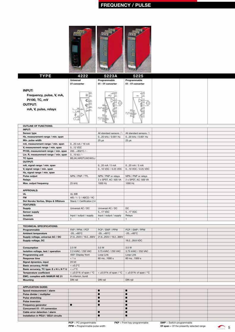
FrEQuENCY / PuLSE
5223AProgrammable
f/I - f/f converter
All standard sensors
0...20 kHz / 0.001 Hz
25 µs
0...20 mA / 5 mA
0...10 VDC / 0.25 VDC
NPN / PNP or relays
2 x SPST, AC: 500 VA
1000 Hz
Universal AC / DC
5...17 VDC
Input / output / supply
1
PCP / SWP / PPW
-20...+60°C
21.6...253 V / 19.2...300 V
3.5 W
3.75 kVAC / 250 VAC
Loop Link
60 ms...1000 s
< ±0.01% of span / °C
DIN rail
PCP = PC-programmable FkP = Front key-programmable SWP = Switch-programmablePPW = Programmable pulse width of span = Of the presently selected range
TYPE INPuT:
Frequency, pulse, v, mA, Pt100, TC, mv
ouTPuT: mA, v, pulse, relays
ouTLINE oF FuNCTIoNS:
INPuT:
Sensor type
Hz, measurement range / min. span
Min. pulse width
mA, measurement range / min. span
v, measurement range / min. span
Pt100, measurement range / min. span
Lin. r, measurement range / min. span
TC types
ouTPuT:
mA, signal range / min. span
v, signal range / min. span
Hz, signal range / min. span
Pulse output
relays
Max. output frequency
APProvALS:
uL
FM
det Norske veritas, Ships & offshore
FEATurES:
Supply
Sensor supply
Isolation
Channels
TECHNICAL SPECIFICATIoNS:
Programmable
Ambient temperature
Supply voltage, universal AC / dC
Supply voltage, dC
Consumption
Isolation voltage, test / operation
Programming unit
response time
Signal dynamics, input
Basic accuracy, Pt100
Basic accuracy, TC type: E J k L N T u
Temperature coefficient
EMC, complies with NAMur NE 21
Mounting
APPLICATIoN GuIdE:
Speed measurement / alarm
Pulse divider / multiplier
Pulse stretching
Pulse inversion
Frequency generator
Concurrent f/I - f/f conversion
Cable error detection / alarm
Installation in PELv / SELv circuits
4222universal
I/f converter
0...20 mA / 16 mA
0...12 VDC
200...+850°C / -
0...10 kW / -
BEJKLNRSTUW3W5Lr
NPN / PNP / TTL
25 kHz
UL 508
AIS / I / 2 / ABCD / IIC
Stand. f. Certification 2.4
Universal AC / DC
Input / output / supply
1
FKP / PPW / PCF
-20...+60°C
21.6...253 V / 19.2...300 V
2.5 W
2.3 kVAC / 250 VAC
4501 Display front
< 1 s
24 bit
< ±0.2°C
< ±1°C
< ±0.01% of span / °C
A criterion, burst
DIN rail
5225Programmable
f/I - f/f converter
All standard sensors
0...20 kHz / 0.001 Hz
25 µs
0...20 mA / 5 mA
0...10 VDC / 0.25 VDC
NPN / PNP or relays
2 x SPST, AC: 500 VA
1000 Hz
DC
5...17 VDC
Relays
1
PCP / SWP / PPW
-20...+60°C
19.2...28.8 VDC
3.5 W
3.75 kVAC / 250 VAC
Loop Link
60 ms...1000 s
< ±0.01% of span / °C
DIN rail
5

Contents
ISoLATorS
FkP = Front key-programmable SWP = Switch-programmable of span = Of the presently selected range
TYPE
INPuT: mA, v, potentiometer
ouTPuT: mA, v
ouTLINE oF FuNCTIoNS:
Number of hardware versions
INPuT:
mA, measurement range / min. span
v, measurement range / min. span
Pt100, measurement range / min. span
Lin. r., measurement range / min. span
TC types
Sensor connection, wires
ouTPuT:
mA, signal range / min. span
v, signal range / min. span
Load impedance
APProvALS:
uL
dNv & GL
IECEx
ATEX zone 2
FM
FEATurES:
Supply
reference voltage / 2-wire supply
Isolation
Channels
TECHNICAL SPECIFICATIoNS:
Programmable
Ambient temperature
Supply voltage, dC
Consumption, typical/max.
Isolation voltage, test / operation
Programming unit
response time
Accuracy
Basic accuracy, mA
Max. operating frequency
Temperature coefficient
EMC, complies with NAMur NE 21
Protection degree
dimensions (H x W x d)
Mounting
APPLICATIoN GuIdE:
Scaling / conversion
Splitter
repeater
Inverted output
Isolation
2-wire transmitter interface
Potentiometer via reference voltage
3103Isolated repeater
1
0...20 mA / 1:1
0...20 mA / 1:1
600 W
UL 61010
Certification 2.4/V1-7-2
Ex nA IIC T4 Gc
II 3 G Ex nA IIC T4
Cl. I Div. 2, Gr. A-D T4
DC
Input / output / supply
1
No
-25...+70°C
16.8...31.2 VDC
0.45 / 0.8 W
2.5 kVAC / 250 VAC
< 7 ms
< ±0.05% of span
< ±8 µA
> 100 Hz
< ±0.01% of span / °C
A criterion, burst
IP20
113 x 6.1 x 115 mm
DIN rail / Power rail
3104Isolated converter
1
0/4...20 mA / 16 mA
0/2...10 VDC / 4 VDC
0/4...20 mA / 16 mA
0/2...10 VDC / 4 VDC
600 W - 10 kW (Vout.)
UL 61010
Certification 2.4/V1-7-2
Ex nA IIC T4 Gc
II 3 G Ex nA IIC T4
Cl. I Div. 2, Gr. A-D T4
DC
- / > 17 V
Input / output / supply
1
SWP
-25...+70°C
16.8...31.2 VDC
0.45 / 1.2 W
2.5 kVAC / 250 VAC
< 7 ms
< ±0.05% of span
< ±8 µA
> 100 Hz
< ±0.01% of span / °C
A criterion, burst
IP 20
113 x 6.1 x 115 mm
DIN rail / Power rail
3108Isolated repeater /
splitter
1
0...20 mA
0...20 mA
2 x 300 W
UL 61010
Certification 2.4/V1-7-2
Ex nA IIC T4 Gc
II 3 G Ex nA IIC T4
Cl. I Div. 2, Gr. A-D T4
DC
Input / output / supply
1
No
-25...+70°C
16.8...31.2 VDC
0.45 / 0.8 W
2.5 kVAC / 250 VAC
< 7 ms
< ±0.05% of span
< ±8 µA
> 100 Hz
< ±0.01% of span / °C
A criterion, burst
IP 20
113 x 6.1 x 115 mm
DIN rail / Power rail
3105Isolated converter
1
0/4...20 mA / 16 mA
0/2...10 VDC / 4 VDC
0/4...20 mA / 16 mA
0/2...10 VDC / 4 VDC
600 W - 10 kW (Vout.)
UL 61010
Certification 2.4/V1-7-2
DC
Input / output / supply
1
SWP
0...+70°C
16.8...31.2 VDC
0.45 / 1.2 W
2.5 kVAC / 250 VAC
< 7 ms
< ±0.2% of span
< ±32 µA
> 100 Hz
< ±0.015% of span / °C
A criterion, burst
IP 20
113 x 6.1 x 115 mm
DIN rail / Power rail
3109Isolated converter /
splitter
1
0/4...20 mA / 16 mA
0/2...10 VDC / 4 VDC
0/4...20 mA / 16 mA
0/2...10 VDC / 4 VDC
2 x 300 W - 10 kW (Vout.)
UL 61010
Certification 2.4/V1-7-2
Ex nA IIC T4 Gc
II 3 G Ex nA IIC T4
Cl. I Div. 2, Gr. A-D T4
DC
- / > 17 V
Input / output / supply
1
SWP
-25...+70°C
16.8...31.2 VDC
0.45 / 1.2 W
2.5 kVAC / 250 VAC
< 7 ms
< ±0.05% of span
< ±8 µA
> 100 Hz
< ±0.01% of span / °C
A criterion, burst
IP 20
113 x 6.1 x 115 mm
DIN rail / Power rail
3114Isolated universal
converter
1
0/4...20 mA / 16 mA
0...10 VDC / 8 VDC
-200...+850°C / 25°C
0...10000 W/ -
BEJKLNRSTUW3W5Lr
2 - 3 - 4
0...20 mA / 16 mA
600 W (mA) - 10 kW (Vout.)
UL 61010
Certification 2.4/V1-7-2
Ex nA IIC T4 Gc
II 3 G Ex nA IIC T4
Cl. I Div. 2, Gr. A-D T4
DC
- / > 15 V
Input / output / supply
1
FKP
-25...+70°C
16.8...31.2 VDC
1.2 W
2.5 kVAC / 250 VAC
4501 / 4590
0.4 / 1.0 s
< ±0.1% of span
< ±8 µA
< ±0.01% of span / °C
A criterion, burst
IP 20
113 x 6.1 x 115 mm
DIN rail / Power rail
6

Contents
ISoLATorS
3185Loop-powered
isolator
2
0/4...20 mA / 1:1
0/4...20 mA / 1:1
UL 61010
Certification 2.4/V1-7-2
Ex nA IIC T4 Gc
II 3 G Ex nA IIC T4
Cl. I Div. 2, Gr. A-D T4
Loop-powered
Input / output
1 or 2
No
-25...+70°C
≤ 1.2 V (drop)
20 mA / channel
2.5 kVAC / 250 VAC
< 5 ms
< ±0.1% of span
< ±8 µA
> 100 Hz
< ±0.01% of span / °C
A criterion, burst
IP20
113 x 6.1 x 115 mm
DIN rail / Power rail
31862-wire transmitter
isolator
2
0/4...20 mA / 1:1
0/4...20 mA / 1:1
UL 61010
Certification 2.4/V1-7-2
Ex nA IIC T4 Gc
II 3 G Ex nA IIC T4
Cl. I Div. 2, Gr. A-D T4
Loop-powered
- / Loop - drop
Input / output
1 or 2
No
-25...+70°C
≤ 2.5 V (drop)
20 mA / channel
2.5 kVAC / 250 VAC
< 5 ms
< ±0.1% of span
< ±8 µA
> 100 Hz
< ±0.01% of span / °C
A criterion, burst
IP20
113 x 6.1 x 115 mm
DIN rail / Power rail
TYPE
INPuT: mA
ouTPuT: mA
ouTLINE oF FuNCTIoNS:
Number of hardware versions
INPuT:
mA, measurement range / min. span
v, measurement range / min. span
ouTPuT:
mA, signal range / min. span
v, signal range / min. span
Load impedance
APProvALS:
uL
dNv & GL
IECEx
ATEX zone 2
FM
FEATurES:
Supply
reference voltage / 2-wire supply
Isolation
Channels
TECHNICAL SPECIFICATIoNS:
Programmable
Ambient temperature
Supply voltage, dC
Consumption, typical/max.
Isolation voltage, test / operation
Programming unit
response time
Accuracy
Basic accuracy, mA
Max. operating frequency
Temperature coefficient
EMC, complies with NAMur NE 21
Protection degree
dimensions (H x W x d)
Mounting
APPLICATIoN GuIdE:
Scaling / conversion
Splitter
repeater
Inverted output
Isolation
2-wire transmitter interface
Potentiometer via reference voltage
of span = Of the presently selected range
7

C O M M U N I C AT I O N F O U N D AT I O N
Contents
5104Arepeater /
power supply
2
0...20 mA / 16 mA
0...10 VDC / 8 VDC
20% of selec. max. value
0...20 mA / 16 mA
0...10 VDC / 0.8 VDC
20% of selec. max. value
4...20 mA
UL 508
Stand. f. Certification 2.4
Universal AC / DC
- / > 17.1 VDC
Input / output / supply
1 or 2
SWP
-20...+60°C
21.6...253 V / 19.2...300 V
< 3 W / 2 channels
3.75 kVAC / 250 VAC
< 25 ms
< ±16 µA
< ±8 mV
< ±0.01% of span / °C
A criterion, burst
DIN rail
5106AHArT® transparent
repeater
2
4...20 mA / 16 mA
HART® communication
4...20 mA / 16 mA
4...20 mA
HART® communication
UL 508
Universal AC / DC
- / > 17 VDC
Input / output / supply
1 or 2
No
-20...+60°C
21.6...253 V / 19.2...300 V
< 3 W / 2 channels
3.75 kVAC / 250 VAC
< 25 ms
< ±16 µA
< ±0.01% of span / °C
A criterion, burst
DIN rail
6185Loop-powered
isolator
3
0...20 mA / 1:1
0...20 mA / 1:1
Loop-powered
Input / output
1, 2 or 4
No
-20...+60°C
20 mA / channel
1.9 VDC + I x Rload
2 kVAC/50 VAC;75 VDC
< 4 ms
< ±16 µA
< ±0.01% of span / °C
DIN rail
SWP = Switch-programmable of span = Of the presently selected range
TYPE
INPuT, dC: mA, mv, v, A, v, HArT® communi cation
ouTPuT: mA, v, HArT® communi cation
ouTLINE oF FuNCTIoNS:
Number of hardware versions
INPuT:
mA, measurement range / min. span
v, measurement range / min. span
Max. offset
digital signal communication
ouTPuT:
mA, signal range / min. span
v, signal range / min. span
Max. offset
2-wire output
digital signal communication
APProvALS:
uL
det Norske veritas, Ships & offshore
FEATurES:
Supply
reference voltage / 2-wire supply
Isolation
Channels
TECHNICAL SPECIFICATIoNS:
Programmable
Ambient temperature
Supply voltage, universal AC / dC
Supply voltage, dC
Consumption
voltage drop
Isolation voltage, test / operation
Programming unit
response time
Signal dynamics, input
Basic accuracy, mA
Basic accuracy, v
Temperature coefficient
EMC, complies with NAMur NE 21
Mounting
APPLICATIoN GuIdE:
Scaling / conversion
Inverted output
Isolation
2-wire transmitter interface
HArT® transparent
Installation in PELv / SELv circuits
ISoLATorS
8
Contents
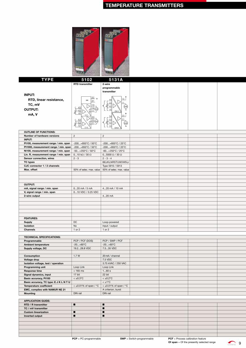
5102rTd transmitter
2
-200...+850°C / 50°C
-200...+850°C / 50°C
-50...+250°C / 50°C
0...10 kW / 30 W2 - 3
50% of selec. max. value
0...20 mA / 5 mA
0...10 VDC / 0.25 VDC
DC
No
1 or 2
PCP / PCF (DOS)
-20...+60°C
19.2...28.8 VDC
1.7 W
Loop Link
< 165 ms
17 bit
< ±0.3°C
< ±0.01% of span / °C
DIN rail
5131A2-wire
programmable
transmitter
2
-200...+850°C / 25°C
-200...+850°C / 25°C
-60...+250°C / 25°C
0...5000 W / 30 W
2 - 3 - 4
BEJKLNRSTUW3W5Lr
Type 5910 / 5913
50% of selec. max. value
4...20 mA / 10 mA
4...20 mA
Loop-powered
Input / output
1 or 2
PCP / SWP / PCF
-20...+60°C
7.5...35 VDC
20 mA / channel
7.5 VDC
3.75 kVAC / 250 VAC
Loop Link
1...60 s
22 bit
< ±0.2°C
< ±1°C
< ±0.01% of span / °C
A criterion, burst
DIN rail
TEMPErATurE TrANSMITTErS
TYPE INPuT:
rTd, linear resistance, TC, mv
ouTPuT: mA, v
ouTLINE oF FuNCTIoNS:
Number of hardware versions
INPuT:
Pt100, measurement range / min. span
Pt1000, measurement range / min. span
Ni100, measurement range / min. span
Lin. r, measurement range / min. span
Sensor connection, wires
TC types
CJC connector 1 / 2 channels
Max. offset
ouTPuT:
mA, signal range / min. span
v, signal range / min. span
2-wire output
FEATurES:
Supply
Isolation
Channels
TECHNICAL SPECIFICATIoNS:
Programmable
Ambient temperature
Supply voltage, dC
Consumption
voltage drop
Isolation voltage, test / operation
Programming unit
response time
Signal dynamics, input
Basic accuracy, Pt100
Basic accuracy, TC type: E J k L N T u
Temperature coefficient
EMC, complies with NAMur NE 21
Mounting
APPLICATIoN GuIdE:
rTd / r transmitter
TC / mv transmitter
Custom linearization
Inverted output
PCP = PC-programmable SWP = Switch-programmable PCF = Process calibration feature of span = Of the presently selected range 9

C O M M U N I C AT I O N F O U N D AT I O N
Contents
6350AProfibus® PA /
FoundationTM Fieldbus
transmitter
2
-100...+100 mA
-200...+850°C / -
-200...+850°C / -
-60...+250°C / -
0...10 kW / -2 - 3 - 4
BEJKLNRSTUW3W5
Internal / external
Type 5910 / 5913
Profibus® PA/FoundationTM F.
KEMA 03ATEX1013 X
II 3 G
Ex nA [nL] IIC T4...T6
Bus-powered
Input / output
1 or 2
Profibus® PA/FoundationTM F.
-40...+60°C
9...32 VDC
< 11 mA / channel
1500 VAC / 50 V
Profibus® PA/FoundationTM F.
1...60 s
24 bit
< ±0.1°C
< ±0.5°C
< ±0.002% of MV / °C
A criterion, burst
DIN rail
6335A2-wire HArT®
transmitter
2
-200...+850°C / 10°C
-200...+850°C / 10°C
-60...+250°C / 10°C
0...7000 W / 25 W
2 - 3 - 4
BEJKLNRSTUW3W5
Internal / external
Type 5910 / 5913
50% of selec. max. value
4...20 mA / 16 mA
4...20 mA
HART® communication
KEMA 10ATEX0006 X
II 3 G
Ex nA [nL] IIC T4...T6
Loop-powered
Input / output
1 or 2
PCP / PCF / HART®
-40...+60°C
8...35 VDC
20 mA / channel
8 VDC
1500 VAC / 50 V
Loop Link / HART®
1...60 s
22 bit
< ±0.1°C
< ±0.5°C
< ±0.005% of span / °C
A criterion, burst
DIN rail
6334A2-wire
programmable
transmitter
2
BEJKLNRSTUW3W5Lr
Internal
50% of selec. max. value
4...20 mA / 16 mA
4...20 mA
KEMA 10ATEX0005 X
II 3 G
Ex nA [nL] IIC T4...T6
Loop-powered
Input / output
1 or 2
PCP / PCF
-40...+60°C
7.2...35 VDC
20 mA / channel
7.2 VDC
1500 VAC / 50 V
Loop Link
1...60 s
18 bit
< ±1°C
< ±0.01% of span / °C
A criterion, burst
DIN rail
6333A2-wire
programmable
transmitter
2
-200...+850°C / 25°C
-200...+850°C / 25°C
-60...+250°C / 25°C
0...10 kW / 30 W
2 - 3
50% of selec. max. value
4...20 mA / 16 mA
4...20 mA
KEMA 10ATEX0007 X
II 3 G
Ex nA [nL] IIC T4...T6
Loop-powered
No
1 or 2
PCP / PCF
-40...+60°C
8...35 VDC
20 mA / channel
8 VDC
Loop Link
0.33...60 s
19 bit
< ±0.3°C
< ±0.01% of span / °C
DIN rail
6331A2-wire
programmable
transmitter
2
-200...+850°C / 25°C
-200...+850°C / 25°C
-60...+250°C / 25°C
0...5000 W / 30 W
2 - 3 - 4
BEJKLNRSTUW3W5Lr
Internal / external
Type 5910 / 5913
50% of selec. max. value
4...20 mA / 16 mA
4...20 mA
KEMA 10ATEX0005 X
II 3 G
Ex nA [nL] IIC T4...T6
Loop-powered
Input / output
1 or 2
PCP / PCF
-40...+60°C
7.2...35 VDC
20 mA / channel
7.2 VDC
1500 VAC / 50 V
Loop Link
1...60 s
20 bit
< ±0.2°C
< ±1°C
< ±0.01% of span / °C
A criterion, burst
DIN rail
TEMPErATurE TrANSMITTErS
PCP = PC-programmable PCF = Process calibration feature of span = Of the presently selected range = FMEDA report of Mv = Of the present measurement value
TYPE INPuT:
rTd, linear resistance, TC, mv, mA, potientometer
ouTPuT: mA, HArT® communication,Profibus® PA,FoundationTM Fieldbus
ouTLINE oF FuNCTIoNS:
Number of hardware versions
INPuT:
mA, measurement range
Pt100, measurement range / min. span
Pt1000, measurement range / min. span
Ni100, measurement range / min. span
Lin. r, measurement range / min. span
Sensor connection, wires
TC types
Cold junction compensation
CJC connector 1 / 2 channels
Max. offset
ouTPuT:
mA, signal range / min. span
2-wire output
digital signal communication
APProvALS:
Ex approval CENELEC
ATEX
FEATurES:
Supply
Isolation
Channels
TECHNICAL SPECIFICATIoNS:
Programmable
Ambient temperature
Supply voltage, dC
Consumption
voltage drop
Isolation voltage, test / operation
Programming unit
response time
Signal dynamics, input
Basic accuracy, Pt100
Basic accuracy, TC type: E J k L N T u
Temperature coefficient
EMC, complies with NAMur NE 21
Mounting
APPLICATIoN GuIdE:
rTd / r transmitter
TC / mv transmitter
Alarm / Control
Custom linearization
differential temperature measurement
Inverted output
HArT® communication
Bus communication
Installation in zone 2
10
Contents
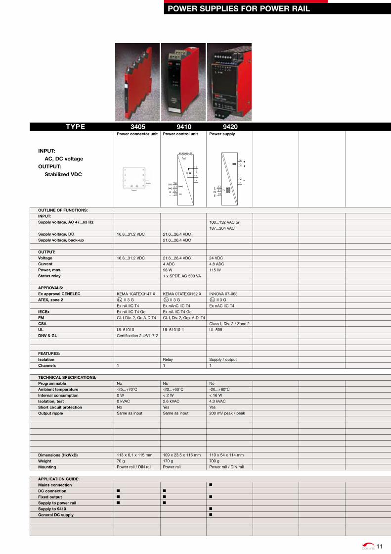
3405Power connector unit
16,8...31,2 VDC
16.8...31.2 VDC
KEMA 10ATEX0147 X
II 3 G
Ex nA IIC T4
Ex nA IIC T4 Gc
Cl. I Div. 2, Gr. A-D T4
UL 61010
Certification 2.4/V1-7-2
1
No
-25...+70°C
0 W
0 kVAC
No
Same as input
113 x 6,1 x 115 mm
70 g
Power rail / DIN rail
9410Power control unit
21.6...26.4 VDC
21.6...26.4 VDC
21.6...26.4 VDC
4 ADC
96 W
1 x SPDT, AC 500 VA
KEMA 07ATEX0152 X
II 3 G
Ex nAnC IIC T4
Ex nA IIC T4 Gc
Cl. I, Div. 2, Grp. A-D, T4
UL 61010-1
Relay
1
No
-20...+60°C
< 2 W
2.6 kVAC
Yes
Same as input
109 x 23.5 x 116 mm
170 g
Power rail
PoWEr SuPPLIES For PoWEr rAIL
TYPE INPuT:
AC, dC voltageouTPuT:
Stabilized vdC
ouTLINE oF FuNCTIoNS:
INPuT:
Supply voltage, AC 47...63 Hz
Supply voltage, dC
Supply voltage, back-up
ouTPuT:
voltage
Current
Power, max.
Status relay
APProvALS:
Ex approval CENELEC
ATEX, zone 2
IECEx
FM
CSA
uL
dNv & GL
FEATurES:
Isolation
Channels
TECHNICAL SPECIFICATIoNS:
Programmable
Ambient temperature
Internal consumption
Isolation, test
Short circuit protection
output ripple
dimensions (HxWxd)
Weight
Mounting
APPLICATIoN GuIdE:
Mains connection
dC connection
Fixed output
Supply to power rail
Supply to 9410
General dC supply
9420Power supply
100...132 VAC or
187...264 VAC
24 VDC
4.8 ADC
115 W
INNOVA 07-063
II 3 G
Ex nAC IIC T4
Class I, Div. 2 / Zone 2
UL 508
Supply / output
1
No
-20...+60°C
< 16 W
4,3 kVAC
Yes
200 mV peak / peak
110 x 54 x 114 mm
700 g
Power rail / DIN rail
11

C O M M U N I C AT I O N F O U N D AT I O N
Contents
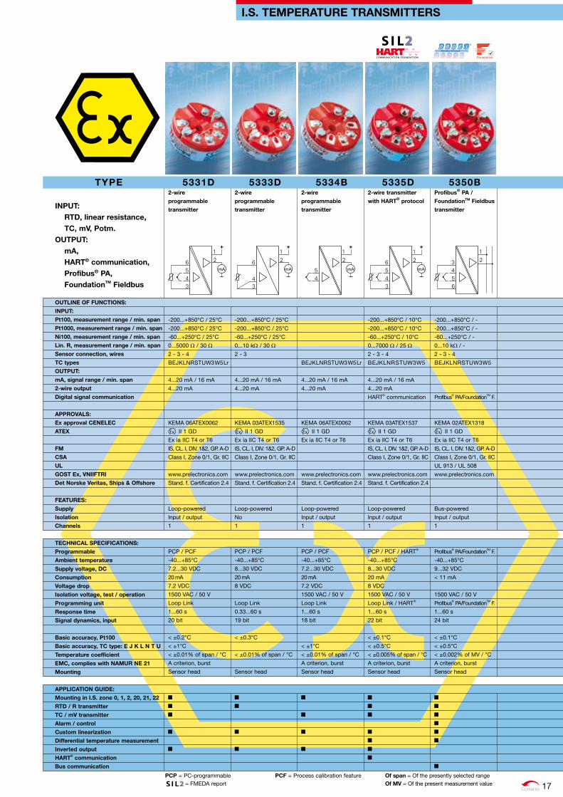
I.S. TEMPErATurE TrANSMITTErS
TYPE
INPuT: rTd, linear resistance, TC, mv, mA, potientometer
ouTPuT: mA, HArT® communication,Profibus® PA,FoundationTM Fieldbus
ouTLINE oF FuNCTIoNS:
INPuT:
mA, measurement range
Pt100, measurement range / min. span
Pt1000, measurement range / min. span
Ni100, measurement range / min. span
Lin. r, measurement range / min. span
Sensor connection, wires
TC types
ouTPuT:
mA, signal range / min. span
2-wire output
digital signal communication
APProvALS:
Ex approval CENELEC
ATEX
FM
CSA
GoST Ex, vNIIFTrI
FEATurES:
Supply
Isolation
Channels
TECHNICAL SPECIFICATIoNS:
Programmable
Ambient temperature
Supply voltage, dC
Consumption
voltage drop
Isolation voltage, test / operation
Programming unit
response time
Signal dynamics, input
Basic accuracy, Pt100
Basic accuracy, TC type: E J k L N T u
Temperature coefficient
EMC, complies with NAMur NE 21
Mounting
APPLICATIoN GuIdE:
Monting in I.S. zone 0, 1 and 2
rTd / r transmitter
TC / mv transmitter
Alarm / control
Custom linearization
differential temperature measurement
Inverted output
HArT® communication
Bus communication
6331B2-wire
programmable
transmitter
-200...+850°C / 25°C
-200...+850°C / 25°C
-60...+250°C / 25°C
0...5000 W / 30 W
2 - 3 - 4
BEJKLNRSTUW3W5Lr
4...20 mA / 16 mA
4...20 mA
KEMA 06ATEX0115
II 1 G
Ex ia IIC T6...T5
www.prelectronics.com
Loop-powered
Input / output
1 or 2
PCP / PCF
-40...+60°C
7.2...30 VDC
20 mA / channel
7.2 VDC
1500 VAC / 50 V
Loop Link
1...60 s
20 bit
< ±0.2°C
< ±1°C
< ±0.01% of span / °C
A criterion, burst
DIN rail
6333B2-wire
programmable
transmitter
-200...+850°C / 25°C
-200...+850°C / 25°C
-60...+250°C / 25°C
0...10 kW / 30 W
2 - 3
4...20 mA / 16 mA
4...20 mA
KEMA 09ATEX0147
II 1 G
Ex ia IIC T6...T5
www.prelectronics.com
Loop-powered
No
1 or 2
PCP / PCF
-40...+60°C
8...28 VDC
20 mA / channel
8 VDC
Loop Link
0.33...60 s
19 bit
< ±0.3°C
< ±0.01% of span / °C
DIN rail
6334B2-wire
programmable
transmitter
BEJKLNRSTUW3W5Lr
4...20 mA / 16 mA
4...20 mA
KEMA 06ATEX0115
II 1 G
Ex ia IIC T6...T5
www.prelectronics.com
Loop-powered
Input / output
1 or 2
PCP / PCF
-40...+60°C
7.2...30 VDC
20 mA / channel
7.2 VDC
1500 VAC / 50 V
Loop Link
1...60 s
18 bit
< ±1°C
< ±0.01% of span / °C
A criterion, burst
DIN rail
6335d2-wire HArT®
transmitter
-200...+850°C / 10°C
-200...+850°C / 10°C
-60...+250°C / 10°C
0...7000 W / 25 W
2 - 3 - 4
BEJKLNRSTUW3W5
4...20 mA / 16 mA
4...20 mA
HART® communication
KEMA 09ATEX0148
II 1 G
Ex ia IIC T6...T5
IS, CL. I, DIV. 1&2, GP. A-D
Class I, Zone 0/1, Gr. IIC
www.prelectronics.com
Loop-powered
Input / output
1 or 2
PCP / PCF / HART®
-40...+60°C
8...28 VDC
20 mA / channel
8 VDC
1500 VAC / 50 V
Loop Link / HART®
1...60 s
22 bit
< ±0.1°C
< ±0.5°C
< ±0.005% of span / °C
A criterion, burst
DIN rail
6350BProfibus® PA /
FoundationTM Fieldbus
transmitter
-100...+100 mA
-200...+850°C / -
-200...+850°C / -
-60...+250°C / -
0...10 kW / -
2 - 3 - 4
BEJKLNRSTUW3W5
Profibus® PA/FoundationTM F.
KEMA 03ATEX1012
II 1 GD
Ex ia IIC T4...T6
IS, CL. I, DIV. 1&2, GP. A-D
Class I, Zone 0/1, Gr. IIC
www.prelectronics.com
Bus-powered
Input / output
1 or 2
Profibus® PA/FoundationTM F.
-40...+60°C
9...32 VDC
< 11 mA / channel
1500 VAC / 50 V
Profibus® PA/FoundationTM F.
1...60 s
24 bit
< ±0.1°C
< ±0.5°C
< ±0.002% of MV / °C
A criterion, burst
DIN rail
PCP = PC-programmable PCF = Process calibration feature of span = Of the presently selected range = FMEDA report of Mv = Of the present measurement value12
C O M M U N I C AT I O N F O U N D AT I O N C O M M U N I C AT I O N F O U N D AT I O N
Contents
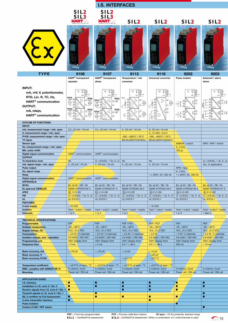
I. S. INTErFACES
PCP = PC-programmable SWP = Switch-programmable PCF = Process calibration feature of span = Of the presently selected range
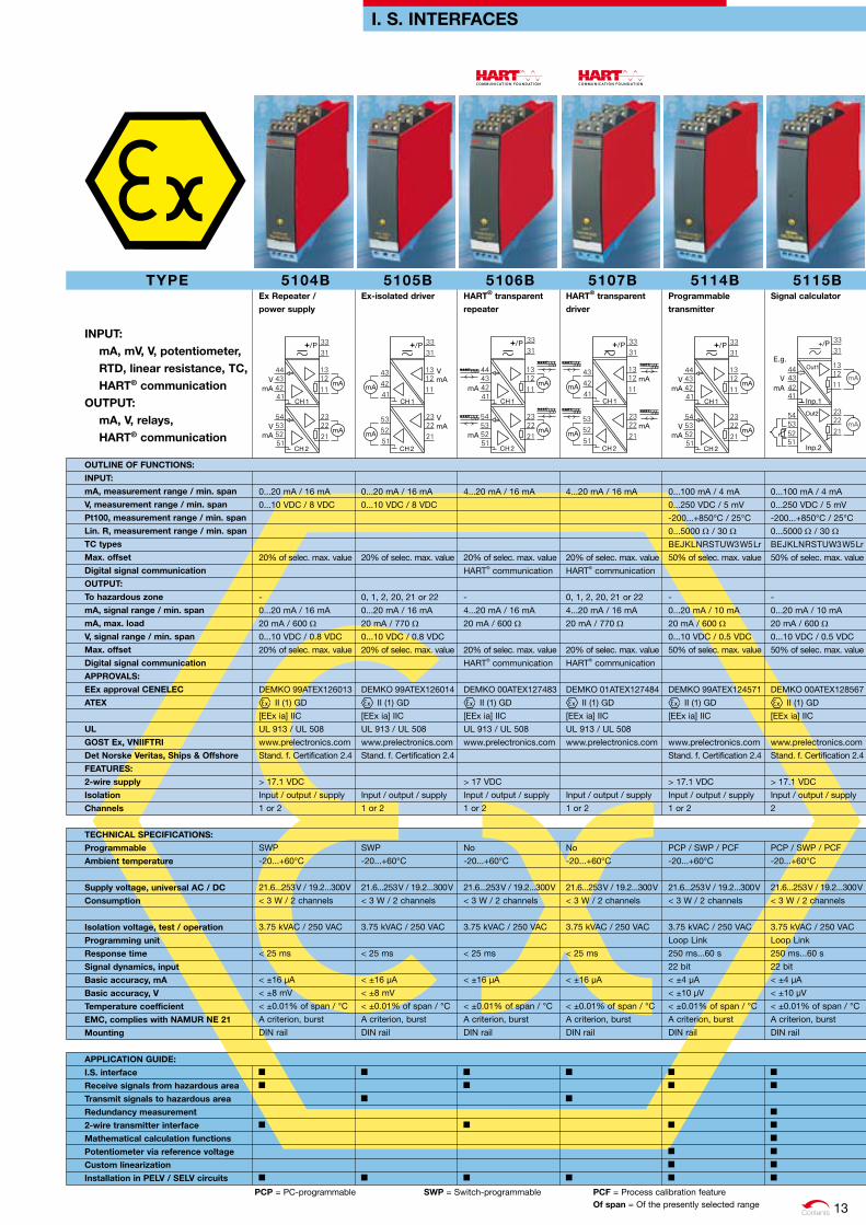
5104BEx repeater /
power supply
0...20 mA / 16 mA
0...10 VDC / 8 VDC
20% of selec. max. value
-
0...20 mA / 16 mA
20 mA / 600 W
0...10 VDC / 0.8 VDC
20% of selec. max. value
DEMKO 99ATEX126013
II (1) GD
[EEx ia] IIC
UL 913 / UL 508
www.prelectronics.com
Stand. f. Certification 2.4
> 17.1 VDC
Input / output / supply
1 or 2
SWP
-20...+60°C
21.6...253 V / 19.2...300 V
< 3 W / 2 channels
3.75 kVAC / 250 VAC
< 25 ms
< ±16 µA
< ±8 mV
< ±0.01% of span / °C
A criterion, burst
DIN rail
5105BEx-isolated driver
0...20 mA / 16 mA
0...10 VDC / 8 VDC
20% of selec. max. value
0, 1, 2, 20, 21 or 22
0...20 mA / 16 mA
20 mA / 770 W
0...10 VDC / 0.8 VDC
20% of selec. max. value
DEMKO 99ATEX126014
II (1) GD
[EEx ia] IIC
UL 913 / UL 508
www.prelectronics.com
Stand. f. Certification 2.4
Input / output / supply
1 or 2
SWP
-20...+60°C
21.6...253 V / 19.2...300 V
< 3 W / 2 channels
3.75 kVAC / 250 VAC
< 25 ms
< ±16 µA
< ±8 mV
< ±0.01% of span / °C
A criterion, burst
DIN rail
5106BHArT® transparent
repeater
4...20 mA / 16 mA
20% of selec. max. value
HART® communication
-
4...20 mA / 16 mA
20 mA / 600 W
20% of selec. max. value
HART® communication
DEMKO 00ATEX127483
II (1) GD
[EEx ia] IIC
UL 913 / UL 508
www.prelectronics.com
> 17 VDC
Input / output / supply
1 or 2
No
-20...+60°C
21.6...253 V / 19.2...300 V
< 3 W / 2 channels
3.75 kVAC / 250 VAC
< 25 ms
< ±16 µA
< ±0.01% of span / °C
A criterion, burst
DIN rail
5107BHArT® transparent
driver
4...20 mA / 16 mA
20% of selec. max. value
HART® communication
0, 1, 2, 20, 21 or 22
4...20 mA / 16 mA
20 mA / 770 W
20% of selec. max. value
HART® communication
DEMKO 01ATEX127484
II (1) GD
[EEx ia] IIC
UL 913 / UL 508
www.prelectronics.com
Input / output / supply
1 or 2
No
-20...+60°C
21.6...253 V / 19.2...300 V
< 3 W / 2 channels
3.75 kVAC / 250 VAC
< 25 ms
< ±16 µA
< ±0.01% of span / °C
A criterion, burst
DIN rail
TYPE
INPuT: mA, mv, v, potentiometer, rTd, linear resistance, TC, HArT® communication
ouTPuT: mA, v, relays, HArT® communication
ouTLINE oF FuNCTIoNS:
INPuT:
mA, measurement range / min. span
v, measurement range / min. span
Pt100, measurement range / min. span
Lin. r, measurement range / min. span
TC types
Max. offset
digital signal communication
ouTPuT:
To hazardous zone
mA, signal range / min. span
mA, max. load
v, signal range / min. span
Max. offset
digital signal communication
APProvALS:
EEx approval CENELEC
ATEX
uL
GoST Ex, vNIIFTrI
det Norske veritas, Ships & offshore
FEATurES:
2-wire supply
Isolation
Channels
TECHNICAL SPECIFICATIoNS:
Programmable
Ambient temperature
Supply voltage, universal AC / dC
Consumption
Isolation voltage, test / operation
Programming unit
response time
Signal dynamics, input
Basic accuracy, mA
Basic accuracy, v
Temperature coefficient
EMC, complies with NAMur NE 21
Mounting
APPLICATIoN GuIdE:
I.S. interface
receive signals from hazardous area
Transmit signals to hazardous area
redundancy measurement
2-wire transmitter interface
Mathematical calculation functions
Potentiometer via reference voltage
Custom linearization
Installation in PELv / SELv circuits
5114BProgrammable
transmitter
0...100 mA / 4 mA
0...250 VDC / 5 mV
-200...+850°C / 25°C
0...5000 W / 30 W
BEJKLNRSTUW3W5Lr
50% of selec. max. value
-
0...20 mA / 10 mA
20 mA / 600 W
0...10 VDC / 0.5 VDC
50% of selec. max. value
DEMKO 99ATEX124571
II (1) GD
[EEx ia] IIC
www.prelectronics.com
Stand. f. Certification 2.4
> 17.1 VDC
Input / output / supply
1 or 2
PCP / SWP / PCF
-20...+60°C
21.6...253 V / 19.2...300 V
< 3 W / 2 channels
3.75 kVAC / 250 VAC
Loop Link
250 ms...60 s
22 bit
< ±4 µA
< ±10 µV
< ±0.01% of span / °C
A criterion, burst
DIN rail
5115BSignal calculator
0...100 mA / 4 mA
0...250 VDC / 5 mV
-200...+850°C / 25°C
0...5000 W / 30 W
BEJKLNRSTUW3W5Lr
50% of selec. max. value
-
0...20 mA / 10 mA
20 mA / 600 W
0...10 VDC / 0.5 VDC
50% of selec. max. value
DEMKO 00ATEX128567
II (1) GD
[EEx ia] IIC
www.prelectronics.com
Stand. f. Certification 2.4
> 17.1 VDC
Input / output / supply
2
PCP / SWP / PCF
-20...+60°C
21.6...253 V / 19.2...300 V
< 3 W / 2 channels
3.75 kVAC / 250 VAC
Loop Link
250 ms...60 s
22 bit
< ±4 µA
< ±10 µV
< ±0.01% of span / °C
A criterion, burst
DIN rail
13
Contents
PCP = PC-programmable SWP = Switch-programmable PCF = Process calibration feature / = FMEDA report PPW = Programmable pulse width of span = Of the presently selected range
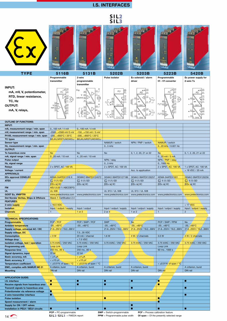
5131B2-wire
programmable
transmitter
0...100 mA / 4 mA
-150...+150 mV / 5 mV
-200...+850°C / 25°C
BEJKLNRSTUW3W5Lr
No
4...20 mA / 10 mA
DEMKO 99ATEX124572
II (1) GD
[EEx ia] IIC
www.prelectronics.com
Input / output
1 or 2
PCP / SWP / PCF
-20...+60°C
7.5...35 VDC
20 mA / channel
< 7.5 VDC
3.75 kVAC / 250 VAC
Loop Link
250 ms...60 s
22 bit
< ±4 µA
< ±10 µV
< ±0.01% of span / °C
A criterion, burst
DIN rail
TYPE
INPuT: mA, mv, v, potentiometer, rTd, linear resistance, TC, Hz
ouTPuT: mA, v, relays,
ouTLINE oF FuNCTIoNS:
INPuT:
mA, measurement range / min. span
mv, measurement range / min. span
Pt100, measurement range / min. span
TC types
Sensor type
Hz, measurement range / min. span
ouTPuT:
To hazardous zone
mA, signal range / min. span
Pulse output
Hz, signal range
relays
voltage / current
APProvALS:
EEx approval CENELEC
ATEX
FM
uL
GoST Ex, vNIIFTrI
det Norske veritas, Ships & offshore
FEATurES:
2-wire supply
Isolation
Channels
TECHNICAL SPECIFICATIoNS:
Programmable
Ambient temperature
Supply voltage, universal AC / dC
Supply voltage, dC
Consumption
voltage drop
Isolation voltage, test / operation
Programming unit
response time
Signal dynamics, input
Basic accuracy, mA
Basic accuracy, v
Temperature coefficient
EMC, complies with NAMur NE 21
Mounting
APPLICATIoN GuIdE:
I.S. interface
receive signals from hazardous area
Transmit signals to hazardous area
Potentiometer via reference voltage
2-wire transmitter interface
Pulse isolation
Speed measurement / alarm
Supply for oN / oFF valves
Installation in PELv / SELv circuits
5116BProgrammable
transmitter
0...100 mA / 4 mA
-2500...+2500 mV / 5 mV
-200...+850°C / 25°C
BEJKLNRSTUW3W5Lr
No
0...20 mA / 10 mA
2 x SPST, AC: 100 VA
KEMA 04ATEX1316 X
II (1) GD
[EEx ia] IIC
AIS / I,II,III / 1 / ABCDEFG
UL 508
www.prelectronics.com
Stand. f. Certification 2.4
> 16.5 VDC
Input / output / supply
1
PCP / PCF
-20...+60°C
21.6...253 V / 19.2...300 V
< 3 W
3.75 kVAC / 250 VAC
Loop Link
250 ms...60 s
22 bit
< ±4 µA
< ±10 µV
< ±0.01% of span / °C
A criterion, burst
DIN rail
5223BProgrammable
f/I - f/f converter
NAMUR / switch
0...20 kHz / 0.001 Hz
No
0...20 mA / 5 mA
NPN / PNP / relay
0...1000 Hz
2 x SPST, AC: 100 VA
KEMA 04ATEX1001
II (1) GD
[EEx ia] IIC
www.prelectronics.com
Input / output / supply
1
PCP / SWP / PPW
-20...+60°C
21.6...253 V / 19.2...300 V
3.5 W
3.75 kVAC / 250 VAC
Loop Link
60 ms...1000 s
< ±0.01% of span / °C
DIN rail
5203BEx solenoid / alarm
driver
NPN / PNP / switch
0, 1, 2, 20, 21 or 22
Acc. to application
DEMKO 99ATEX126257
II (1) GD
[EEx ia] IIC
UL 913 / UL 508
www.prelectronics.com
Input / output / supply
1 or 2
No
-20...+60°C
21.6...253 V / 19.2...300 V
4 W / 2 channels
3.75 kVAC / 250 VAC
A criterion, burst
DIN rail
5420BEx power supply for
2-wire Tx
0, 1, 2, 20, 21 or 22
1 x SPDT, AC: 100 VA
> 18 VDC / 20 mA
DEMKO 99ATEX126256
II (1) GD
[EEx ia] IIC
www.prelectronics.com
> 17 VDC
Input / output / supply
2
No
-20...+60°C
21.6...253 V / 19.2...300 V
4 W / 2 channels
3.75 kVAC / 250 VAC
A criterion, burst
DIN rail
5202BPulse isolator
NAMUR / switch
0...5 kHz
No
NPN / relay
0...5 kHz
2 x SPDT, AC: 100 VA
DEMKO 99ATEX127186
II (1) GD
[EEx ia] IIC
UL 913 / UL 508
www.prelectronics.com
Input / output / supply
2 or 4
SWP
-20...+60°C
21.6...253 V / 19.2...300 V
1.6 W
3.75 kVAC / 250 VAC
A criterion, burst
DIN rail
I.S. INTErFACES
14
C O M M U N I C AT I O N F O U N D AT I O N C O M M U N I C AT I O N F O U N D AT I O N
Contents
FkP = Front key-programmable PCF = Process calibration feature of span = Of the presently selected range = Certified/Full assessment = Certified/Full assessment. When a combination of 2 units/channels is used
TYPE INPuT:
mA, mv, v, potentiometer, rTd, Lin. r, TC, Hz, HArT® communi cation
ouTPuT: mA, relays, HArT® communi cation
ouTLINE oF FuNCTIoNS:
INPuT:
mA, measurement range / min. span
v, measurement range / min. span
Pt100, measurement range / min. span
TC types
Sensor type
Hz, measurement range / min. span
Min. pulse width
digital signal communication
ouTPuT:
To hazardous zone
mA, signal range / min. span
Pulse output
Hz, signal range
relay
digital signal communication
APProvALS:
IECEx
Ex approval CENELEC
ATEX
FM
uL
FEATurES:
2-wire supply
Isolation
Channels
TECHNICAL SPECIFICATIoNS:
Programmable
Ambient temperature
Supply voltage, dC
Consumption
Isolation voltage, test / operation
Programming unit
response time
Basic accuracy, mA
Basic accuracy, v
Basic accuracy, Pt100
Temperature coefficient
EMC, complies with NAMur NE 21
Mounting
APPLICATIoN GuIdE:
I.S. interface
Installation in I.S. zone 2 / div. 2
receive signals from I.S. zone 0 / div. 1
Transmit signals to I.S. zone 0 / div. 1
SIL 2-certified via Full Assessment
2-wire transmitter interface
Pulse isolation
Control of oN / oFF valves
I.S. INTErFACES
9203Solenoid / alarm
driver
NPN / PNP / switch
Cl. I,II,III;Div. 1 Gr. A...G
Acc. to application
[Ex ia] IIC / IIB / IIA
KEMA 07ATEX0147 X
II (1) GD
Cl. I,II,III;Div. 1 Gr. A...G
UL 61010-1
Input / output / supply
1 eller 2
FKP
-20...+60°C
19.2...31.2 VDC
< 3,5 W / 2 channels
2.6 kVAC / 250 VAC
4501 Display front
< 10 ms
A criterion, burst
Power rail / DIN rail
9106HArT® transparent
repeater
3.5...23 mA / 16 mA
HART® communication
No
4...20 mA / 16 mA
HART® communication
[Ex ia] IIC / IIB / IIA
KEMA 07ATEX0150 X
II (1) GD
Cl. I,II,III;Div. 1 Gr. A...G
UL 61010-1
> 16 VDC
Input / output / supply
1 or 2
FKP
-20...+60°C
19.2...31.2 VDC
< 3,5 W / 2 channels
2.6 kVAC / 250 VAC
4501 Display front
< 5 ms
< ±16 µA
< ±0.01% of span / °C
A criterion, burst
Power rail / DIN rail
9107HArT® transparent
driver
3.5...23 mA / 16 mA
HART® communication
Cl. I,II,III;Div. 1 Gr. A...G
4...20 mA / 16 mA
HART® communication
[Ex ia] IIC / IIB / IIA
KEMA 07ATEX0151 X
II (1) GD
Cl. I,II,III;Div. 1 Gr. A...G
UL 61010-1
Input / output / supply
1 or 2
FKP
-20...+60°C
19.2...31.2 VDC
< 3,5 W / 2 channels
2.6 kVAC / 250 VAC
4501 Display front
< 5 ms
< ±16 µA
< ±0.01% of span / °C
A criterion, burst
Power rail / DIN rail
9116universal converter
0...20 mA / 16 mA
0...12 VDC / 0.8 V
-200...+850°C / 25°C
BEJKLNRSTUW3W5Lr
No
0...20 mA / 16 mA
1 x SPST, AC: 500 VA
[Ex ia] IIC / IIB / IIA
KEMA 07ATEX0149 X
II (1) GD
Cl. I,II,III;Div. 1 Gr. A...G
UL 61010-1
> 16 VDC
Input / output / supply
1
FKP / PCF
-20...+60°C
19.2...31.2 VDC
< 3,5 W
2.6 kVAC / 250 VAC
4501 Display front
0.4 / 1...60 s
< ±4 µA
< ±20 µV
< ±0.2 °C
< ±0.01% of span / °C
A criterion, burst
Power rail / DIN rail
9113Temperature / mA
converter
0...20 mA / 16 mA
-200...+850°C / 25°C
BEJKLNRSTUW3W5Lr
No
0...20 mA / 16 mA
[Ex ia] IIC / IIB / IIA
KEMA 07ATEX0148 X
II (1) GD
Cl. I,II,III;Div. 1 Gr. A...G
UL 61010-1
Input / output / supply
1 or 2
FKP / PCF
-20...+60°C
19.2...31.2 VDC
< 3,5 W / 2 channels
2.6 kVAC / 250 VAC
4501 Display front
0.4 / 1...60 s
< ±4 µA
< ±0.2 °C
< ±0.01% of span / °C
A criterion, burst
Power rail / DIN rail
9202Pulse isolator
NAMUR / switch
0...5 kHz
100 µs
NPN / relay
0...5 kHz
1 x SPST, AC: 500 VA
[Ex ia] IIC / IIB / IIA
KEMA 07ATEX0146 X
II (1) GD
Cl. I,II,III;Div. 1 Gr. A...G
UL 61010-1
Input / output / supply
1 or 2
FKP
-20...+60°C
19.2...31.2 VDC
< 3 W / 2 channels
2.6 kVAC / 250 VAC
4501 Display front
200 ms
A criterion, burst
Power rail / DIN rail
15

C O M M U N I C AT I O N F O U N D AT I O N
Contents
TEMPErATurE TrANSMITTErS
TYPE
INPuT: rTd, linear resistance, TC, mv, Potm.
ouTPuT: mA, HArT® communication,Profibus® PA,FoundationTM Fieldbus
ouTLINE oF FuNCTIoNS:
Number of hardware versions
INPuT:
Pt100, measurement range / min. span
Pt1000, measurement range / min. span
Ni100, measurement range / min. span
Lin. r, measurement range / min. span
Sensor connection, wires
TC types
CJC connector 1 / 2 channels
Max. offset
ouTPuT:
mA, signal range / min. span
2-wire output
digital signal communication
APProvALS:
Ex approval CENELEC
ATEX
uL
det Norske veritas, Ships & offshore
FEATurES:
Supply
Isolation
Channels
TECHNICAL SPECIFICATIoNS:
Programmable
Ambient temperature
Supply voltage, universal AC / dC
Supply voltage, dC
Consumption
voltage drop
Isolation voltage, test / operation
Programming unit
response time
Signal dynamics, input
Basic accuracy, Pt100
Basic accuracy, TC type: E J k L N T u
Temperature coefficient
EMC, complies with NAMur NE 21
Mounting
APPLICATIoN GuIdE:
rTd / r transmitter
TC / mv transmitter
Alarm / Control
Custom linearization
differential temperature measurement
Inverted output
HArT® communication
Bus communication
5335A2-wire transmitter
with HArT® protocol
1
-200...+850°C / 10°C
-200...+850°C / 10°C
-60...+250°C / 10°C
0...7000 W / 25 W
2 - 3 - 4
BEJKLNRSTUW3W5
50% of selec. max. value
4...20 mA / 16 mA
4...20 mA
HART® communication
KEMA 03ATEX1508 X
II 3 GD
Ex nA [nL] IIC T4...T6
Stand. f. Certification 2.4
Loop-powered
Input / output
1
PCP / PCF / HART®
-40...+85°C
8...35 VDC
20 mA
8 VDC
1500 VAC / 50 V
Loop Link / HART®
1...60 s
22 bit
< ±0.1°C
< ±0.5°C
< ±0.005% of span / °C
A criterion, burst
Sensor head
5334A2-wire
programmable
transmitter
1
BEJKLNRSTUW3W5Lr
50% of selec. max. value
4...20 mA / 16 mA
4...20 mA
KEMA 10ATEX0002 X
II 3 GD
Ex nA [nL] IIC T4...T6
Stand. f. Certification 2.4
Loop-powered
Input / output
1
PCP / PCF
-40...+85°C
7.2...35 VDC
20 mA
7.2 VDC
1500 VAC / 50 V
Loop Link
1...60 s
18 bit
< ±1°C
< ±0.01% of span / °C
A criterion, burst
Sensor head
5333A2-wire
programmable
transmitter
1
-200...+850°C / 25°C
-200...+850°C / 25°C
-60...+250°C / 25°C
0...10 kW / 30 W
2 - 3
50% of selec. max. value
4...20 mA / 16 mA
4...20 mA
KEMA 10ATEX0003 X
II 3 GD
Ex nA [nL] IIC T4...T6
Stand. f. Certification 2.4
Loop-powered
No
1
PCP / PCF
-40...+85°C
8...35 VDC
20 mA
8 VDC
Loop Link
0.33...60 s
19 bit
< ±0.3°C
< ±0.01% of span / °C
Sensor head
5331A2-wire
programmable
transmitter
1
-200...+850°C / 25°C
-200...+850°C / 25°C
-60...+250°C / 25°C
0...5000 W / 30 W
2 - 3 - 4
BEJKLNRSTUW3W5Lr
50% of selec. max. value
4...20 mA / 16 mA
4...20 mA
KEMA 10ATEX0002 X
II 3 GD
Ex nA [nL] IIC T4...T6
Stand. f. Certification 2.4
Loop-powered
Input / output
1
PCP / PCF
-40...+85°C
7.2...35 VDC
20 mA
7.2 VDC
1500 VAC / 50 V
Loop Link
1...60 s
20 bit
< ±0.2°C
< ±1°C
< ±0.01% of span / °C
A criterion, burst
Sensor head
5350AProfibus® PA /
FoundationTM Fieldbus
transmitter
1
-200...+850°C / -
-200...+850°C / -
-60...+250°C / -
0...10 kW / -2 - 3 - 4
BEJKLNRSTUW3W5
Profibus® PA/FoundationTM F.
KEMA 03ATEX1011 X
II 3 GD
Ex nA [nL] IIC T4...T6
UL 1604, UL 508
Bus-powered
Input / output
1
Profibus® PA/FoundationTM F.
-40...+85°C
9...32 VDC
< 11 mA
1500 VAC / 50 V
Profibus® PA/FoundationTM F.
1...60 s
24 bit
< ±0.1°C
< ±0.5°C
< ±0.002% of MV / °C
A criterion, burst
Sensor head
PCP = PC-programmable PCF = Process calibration feature of span = Of the presently selected range = FMEDA report of Mv = Of the present measurement value16
C O M M U N I C AT I O N F O U N D AT I O N
Contents
I.S. TEMPErATurE TrANSMITTErS
TYPE
INPuT: rTd, linear resistance, TC, mv, Potm.
ouTPuT: mA, HArT® communication,Profibus® PA,FoundationTM Fieldbus
ouTLINE oF FuNCTIoNS:
INPuT:
Pt100, measurement range / min. span
Pt1000, measurement range / min. span
Ni100, measurement range / min. span
Lin. r, measurement range / min. span
Sensor connection, wires
TC types
ouTPuT:
mA, signal range / min. span
2-wire output
digital signal communication
APProvALS:
Ex approval CENELEC
ATEX
FM
CSA
uL
GoST Ex, vNIIFTrI
det Norske veritas, Ships & offshore
FEATurES:
Supply
Isolation
Channels
TECHNICAL SPECIFICATIoNS:
Programmable
Ambient temperature
Supply voltage, dC
Consumption
voltage drop
Isolation voltage, test / operation
Programming unit
response time
Signal dynamics, input
Basic accuracy, Pt100
Basic accuracy, TC type: E J k L N T u
Temperature coefficient
EMC, complies with NAMur NE 21
Mounting
APPLICATIoN GuIdE:
Mounting in I.S. zone 0, 1, 2, 20, 21, 22
rTd / r transmitter
TC / mv transmitter
Alarm / control
Custom linearization
differential temperature measurement
Inverted output
HArT® communication
Bus communication
5331d2-wire
programmable
transmitter
-200...+850°C / 25°C
-200...+850°C / 25°C
-60...+250°C / 25°C
0...5000 W / 30 W
2 - 3 - 4
BEJKLNRSTUW3W5Lr
4...20 mA / 16 mA
4...20 mA
KEMA 06ATEX0062
II 1 GD
Ex ia IIC T4 or T6
IS, CL. I, DIV. 1&2, GP. A-D
Class I, Zone 0/1, Gr. IIC
www.prelectronics.com
Stand. f. Certification 2.4
Loop-powered
Input / output
1
PCP / PCF
-40...+85°C
7.2...30 VDC
20 mA
7.2 VDC
1500 VAC / 50 V
Loop Link
1...60 s
20 bit
< ±0.2°C
< ±1°C
< ±0.01% of span / °C
A criterion, burst
Sensor head
5350BProfibus® PA /
FoundationTM Fieldbus
transmitter
-200...+850°C / -
-200...+850°C / -
-60...+250°C / -
0...10 kW / -2 - 3 - 4
BEJKLNRSTUW3W5
Profibus® PA/FoundationTM F.
KEMA 02ATEX1318
II 1 GD
Ex ia IIC T4 or T6
IS, CL. I, DIV. 1&2, GP. A-D
Class I, Zone 0/1, Gr. IIC
UL 913 / UL 508
www.prelectronics.com
Bus-powered
Input / output
1
Profibus® PA/FoundationTM F.
-40...+85°C
9...32 VDC
< 11 mA
1500 VAC / 50 V
Profibus® PA/FoundationTM F.
1...60 s
24 bit
< ±0.1°C
< ±0.5°C
< ±0.002% of MV / °C
A criterion, burst
Sensor head
5335d2-wire transmitter
with HArT® protocol
-200...+850°C / 10°C
-200...+850°C / 10°C
-60...+250°C / 10°C
0...7000 W / 25 W
2 - 3 - 4
BEJKLNRSTUW3W5
4...20 mA / 16 mA
4...20 mA
HART® communication
KEMA 03ATEX1537
II 1 GD
Ex ia IIC T4 or T6
IS, CL. I, DIV. 1&2, GP. A-D
Class I, Zone 0/1, Gr. IIC
www.prelectronics.com
Stand. f. Certification 2.4
Loop-powered
Input / output
1
PCP / PCF / HART®
-40...+85°C
8...30 VDC
20 mA
8 VDC
1500 VAC / 50 V
Loop Link / HART®
1...60 s
22 bit
< ±0.1°C
< ±0.5°C
< ±0.005% of span / °C
A criterion, burst
Sensor head
5333d2-wire
programmable
transmitter
-200...+850°C / 25°C
-200...+850°C / 25°C
-60...+250°C / 25°C
0...10 kW / 30 W
2 - 3
4...20 mA / 16 mA
4...20 mA
KEMA 03ATEX1535
II 1 GD
Ex ia IIC T4 or T6
IS, CL. I, DIV. 1&2, GP. A-D
Class I, Zone 0/1, Gr. IIC
www.prelectronics.com
Stand. f. Certification 2.4
Loop-powered
No
1
PCP / PCF
-40...+85°C
8...30 VDC
20 mA
8 VDC
Loop Link
0.33...60 s
19 bit
< ±0.3°C
< ±0.01% of span / °C
Sensor head
5334B2-wire
programmable
transmitter
BEJKLNRSTUW3W5Lr
4...20 mA / 16 mA
4...20 mA
KEMA 06ATEX0062
II 1 GD
Ex ia IIC T4 or T6
www.prelectronics.com
Stand. f. Certification 2.4
Loop-powered
Input / output
1
PCP / PCF
-40...+85°C
7.2...30 VDC
20 mA
7.2 VDC
1500 VAC / 50 V
Loop Link
1...60 s
18 bit
< ±1°C
< ±0.01% of span / °C
A criterion, burst
Sensor head
PCP = PC-programmable PCF = Process calibration feature of span = Of the presently selected range = FMEDA report of Mv = Of the present measurement value 17
Contents
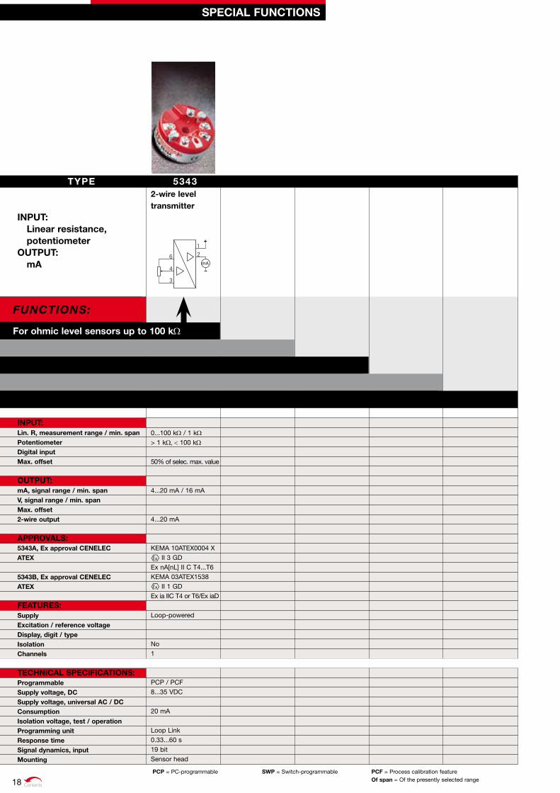
For ohmic level sensors up to 100 kW
Functions:
53432-wire level transmitter
0...100 kW / 1 kW > 1 kW, < 100 kW 50% of selec. max. value 4...20 mA / 16 mA 4...20 mA KEMA 10ATEX0004 X II 3 GD Ex nA[nL] II C T4...T6 KEMA 03ATEX1538 II 1 GD Ex ia IIC T4 or T6/Ex iaD Loop-powered No 1 PCP / PCF 8...35 VDC 20 mA Loop Link 0.33...60 s 19 bit Sensor head
SPECIAL FuNCTIoNS
PCP = PC-programmable SWP = Switch-programmable PCF = Process calibration feature of span = Of the presently selected range
TYPE
INPuT: Linear resistance, potentiometer
ouTPuT: mA
INPuT:Lin. r, measurement range / min. span Potentiometer digital input Max. offset
ouTPuT: mA, signal range / min. span v, signal range / min. span Max. offset 2-wire output
APProvALS:5343A, Ex approval CENELEC ATEX 5343B, Ex approval CENELEC ATEX
FEATurES:Supply Excitation / reference voltage display, digit / type Isolation Channels
TECHNICAL SPECIFICATIoNS:Programmable Supply voltage, dC Supply voltage, universal AC / dC Consumption Isolation voltage, test / operation Programming unit response time Signal dynamics, input Mounting
18
1211
232221
3231
262524
mA
43
4241
Contents
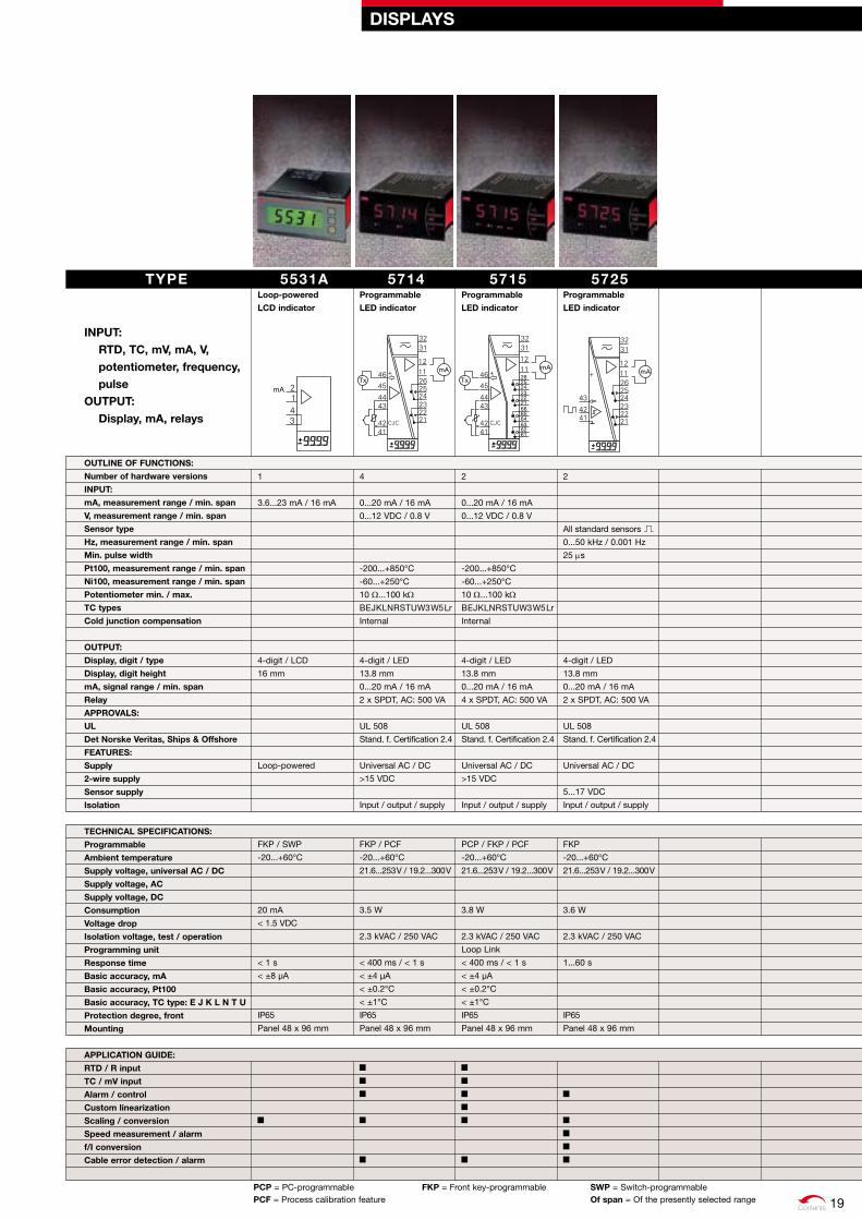
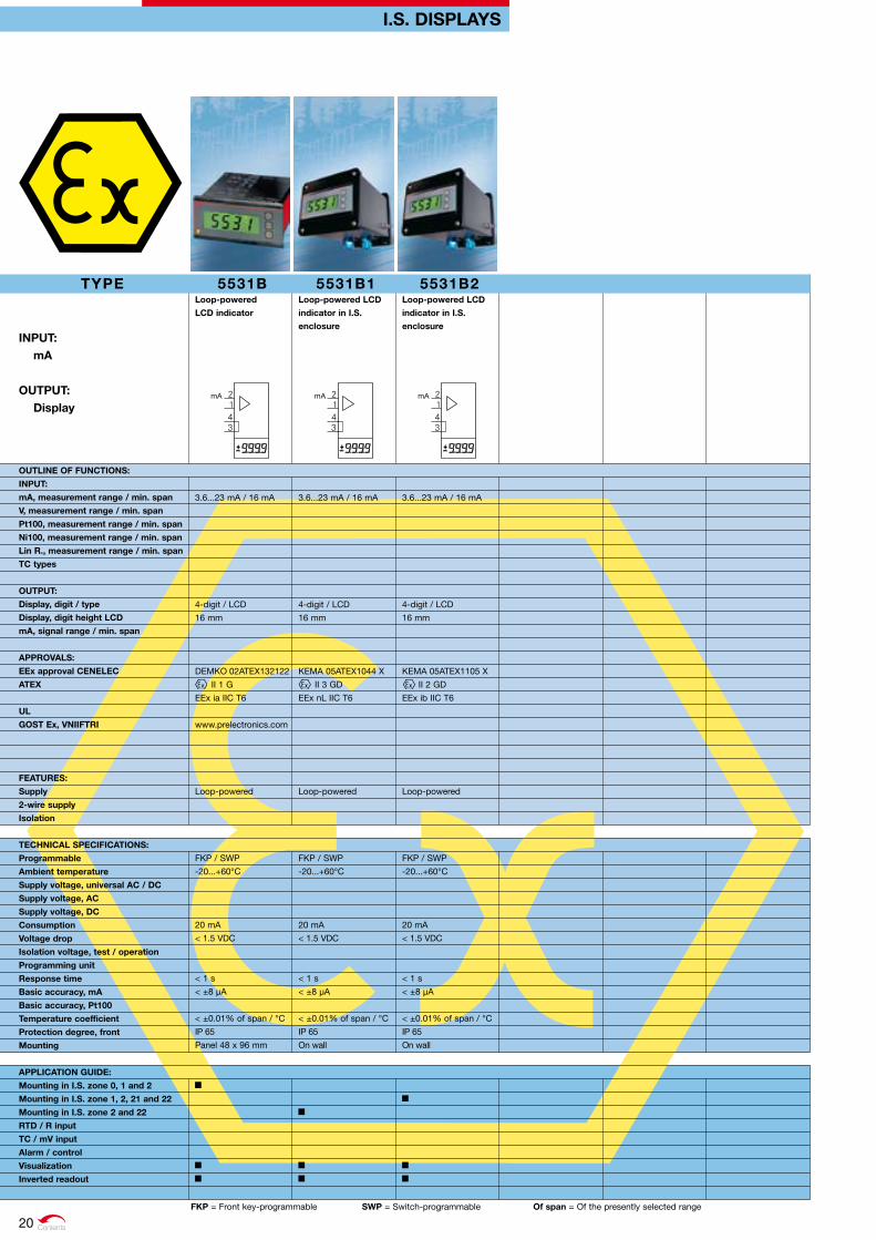
5531ALoop-powered
LCd indicator
1
3.6...23 mA / 16 mA
4-digit / LCD
16 mm
Loop-powered
FKP / SWP
-20...+60°C
20 mA
< 1.5 VDC
< 1 s
< ±8 µA
IP65
Panel 48 x 96 mm
5714Programmable
LEd indicator
4
0...20 mA / 16 mA
0...12 VDC / 0.8 V
-200...+850°C
-60...+250°C
10 W...100 kWBEJKLNRSTUW3W5Lr
Internal
4-digit / LED
13.8 mm
0...20 mA / 16 mA
2 x SPDT, AC: 500 VA
UL 508
Stand. f. Certification 2.4
Universal AC / DC
>15 VDC
Input / output / supply
FKP / PCF
-20...+60°C
21.6...253 V / 19.2...300 V
3.5 W
2.3 kVAC / 250 VAC
< 400 ms / < 1 s
< ±4 µA
< ±0.2°C
< ±1°C
IP65
Panel 48 x 96 mm
5715Programmable
LEd indicator
2
0...20 mA / 16 mA
0...12 VDC / 0.8 V
-200...+850°C
-60...+250°C
10 W...100 kWBEJKLNRSTUW3W5Lr
Internal
4-digit / LED
13.8 mm
0...20 mA / 16 mA
4 x SPDT, AC: 500 VA
UL 508
Stand. f. Certification 2.4
Universal AC / DC
>15 VDC
Input / output / supply
PCP / FKP / PCF
-20...+60°C
21.6...253 V / 19.2...300 V
3.8 W
2.3 kVAC / 250 VAC
Loop Link
< 400 ms / < 1 s
< ±4 µA
< ±0.2°C
< ±1°C
IP65
Panel 48 x 96 mm
dISPLAYS
PCP = PC-programmable FkP = Front key-programmable SWP = Switch-programmablePCF = Process calibration feature of span = Of the presently selected range
TYPE
INPuT: rTd, TC, mv, mA, v, potentiometer, frequency, pulse
ouTPuT:
display, mA, relays
ouTLINE oF FuNCTIoNS:
Number of hardware versions
INPuT:
mA, measurement range / min. span
v, measurement range / min. span
Sensor type
Hz, measurement range / min. span
Min. pulse width
Pt100, measurement range / min. span
Ni100, measurement range / min. span
Potentiometer min. / max.
TC types
Cold junction compensation
ouTPuT:
display, digit / type
display, digit height
mA, signal range / min. span
relay
APProvALS:
uL
det Norske veritas, Ships & offshore
FEATurES:
Supply
2-wire supply
Sensor supply
Isolation
TECHNICAL SPECIFICATIoNS:
Programmable
Ambient temperature
Supply voltage, universal AC / dC
Supply voltage, AC
Supply voltage, dC
Consumption
voltage drop
Isolation voltage, test / operation
Programming unit
response time
Basic accuracy, mA
Basic accuracy, Pt100
Basic accuracy, TC type: E J k L N T u
Protection degree, front
Mounting
APPLICATIoN GuIdE:
rTd / r input
TC / mv input
Alarm / control
Custom linearization
Scaling / conversion
Speed measurement / alarm
f/I conversion
Cable error detection / alarm
5725Programmable
LEd indicator
2
All standard sensors
0...50 kHz / 0.001 Hz
25 µs
4-digit / LED
13.8 mm
0...20 mA / 16 mA
2 x SPDT, AC: 500 VA
UL 508
Stand. f. Certification 2.4
Universal AC / DC
5...17 VDC
Input / output / supply
FKP
-20...+60°C
21.6...253 V / 19.2...300 V
3.6 W
2.3 kVAC / 250 VAC
1...60 s
IP65
Panel 48 x 96 mm
19
Contents
I.S. dISPLAYS
TYPE
INPuT: mA
ouTPuT: display
ouTLINE oF FuNCTIoNS:
INPuT:
mA, measurement range / min. span
v, measurement range / min. span
Pt100, measurement range / min. span
Ni100, measurement range / min. span
Lin r., measurement range / min. span
TC types
ouTPuT:
display, digit / type
display, digit height LCd
mA, signal range / min. span
APProvALS:
EEx approval CENELEC
ATEX
uL
GoST Ex, vNIIFTrI
FEATurES:
Supply
2-wire supply
Isolation
TECHNICAL SPECIFICATIoNS:
Programmable
Ambient temperature
Supply voltage, universal AC / dC
Supply voltage, AC
Supply voltage, dC
Consumption
voltage drop
Isolation voltage, test / operation
Programming unit
response time
Basic accuracy, mA
Basic accuracy, Pt100
Temperature coefficient
Protection degree, front
Mounting
APPLICATIoN GuIdE:
Mounting in I.S. zone 0, 1 and 2
Mounting in I.S. zone 1, 2, 21 and 22
Mounting in I.S. zone 2 and 22
rTd / r input
TC / mv input
Alarm / control
visualization
Inverted readout
5531B1Loop-powered LCd
indicator in I.S.
enclosure
3.6...23 mA / 16 mA
4-digit / LCD
16 mm
KEMA 05ATEX1044 X
II 3 GD
EEx nL IIC T6
Loop-powered
FKP / SWP
-20...+60°C
20 mA
< 1.5 VDC
< 1 s
< ±8 µA
< ±0.01% of span / °C
IP 65
On wall
5531BLoop-powered
LCd indicator
3.6...23 mA / 16 mA
4-digit / LCD
16 mm
DEMKO 02ATEX132122
II 1 G
EEx ia IIC T6
www.prelectronics.com
Loop-powered
FKP / SWP
-20...+60°C
20 mA
< 1.5 VDC
< 1 s
< ±8 µA
< ±0.01% of span / °C
IP 65
Panel 48 x 96 mm
FkP = Front key-programmable SWP = Switch-programmable of span = Of the presently selected range
5531B2Loop-powered LCd
indicator in I.S.
enclosure
3.6...23 mA / 16 mA
4-digit / LCD
16 mm
KEMA 05ATEX1105 X
II 2 GD
EEx ib IIC T6
Loop-powered
FKP / SWP
-20...+60°C
20 mA
< 1.5 VDC
< 1 s
< ±8 µA
< ±0.01% of span / °C
IP 65
On wall
20
Contents
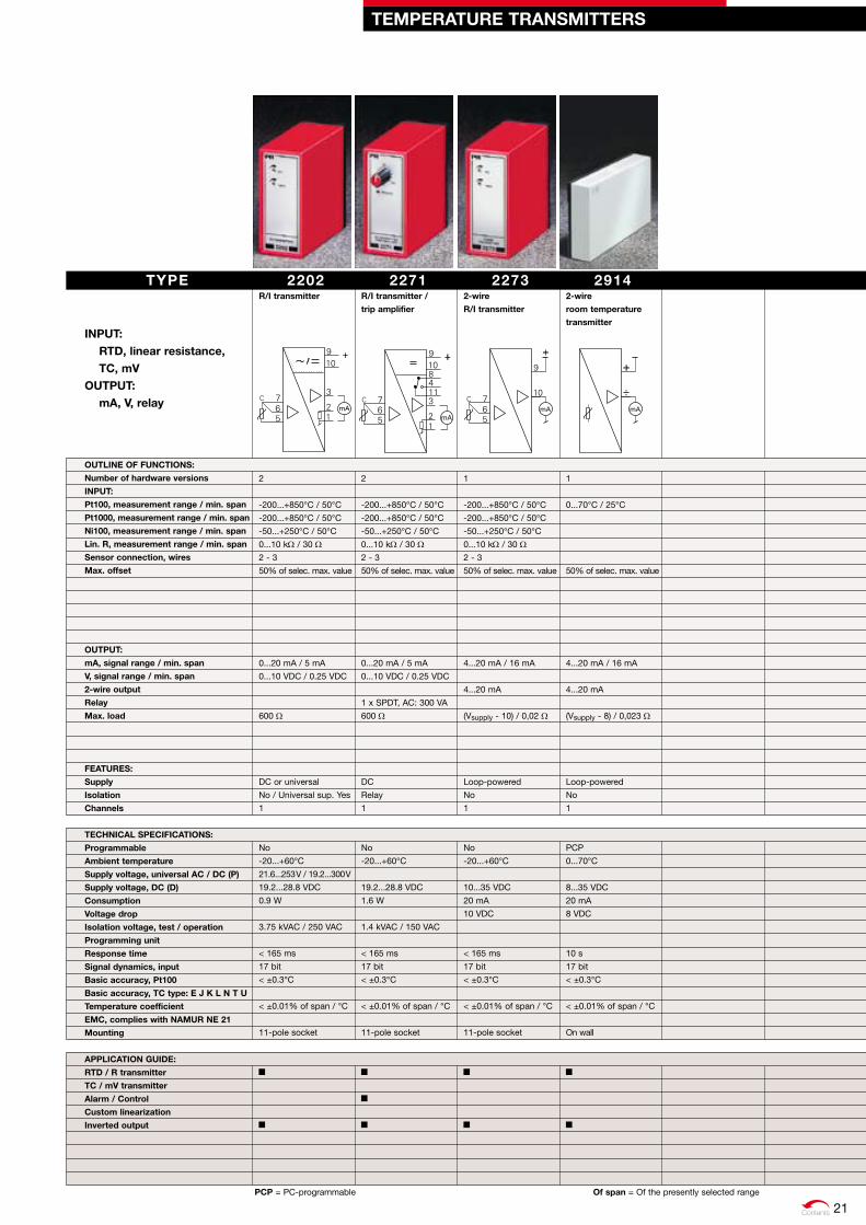
2202r/I transmitter
2
-200...+850°C / 50°C
-200...+850°C / 50°C
-50...+250°C / 50°C
0...10 kW / 30 W2 - 3
50% of selec. max. value
0...20 mA / 5 mA
0...10 VDC / 0.25 VDC
600 W
DC or universal
No / Universal sup. Yes
1
No
-20...+60°C
21.6...253 V / 19.2...300 V
19.2...28.8 VDC
0.9 W
3.75 kVAC / 250 VAC
< 165 ms
17 bit
< ±0.3°C
< ±0.01% of span / °C
11-pole socket
2271r/I transmitter /
trip amplifier
2
-200...+850°C / 50°C
-200...+850°C / 50°C
-50...+250°C / 50°C
0...10 kW / 30 W2 - 3
50% of selec. max. value
0...20 mA / 5 mA
0...10 VDC / 0.25 VDC
1 x SPDT, AC: 300 VA
600 W
DC
Relay
1
No
-20...+60°C
19.2...28.8 VDC
1.6 W
1.4 kVAC / 150 VAC
< 165 ms
17 bit
< ±0.3°C
< ±0.01% of span / °C
11-pole socket
29142-wire
room temperature
transmitter
1
0...70°C / 25°C
50% of selec. max. value
4...20 mA / 16 mA
4...20 mA
(Vsupply - 8) / 0,023 W
Loop-powered
No
1
PCP
0...70°C
8...35 VDC
20 mA
8 VDC
10 s
17 bit
< ±0.3°C
< ±0.01% of span / °C
On wall
22732-wire
r/I transmitter
1
-200...+850°C / 50°C
-200...+850°C / 50°C
-50...+250°C / 50°C
0...10 kW / 30 W2 - 3
50% of selec. max. value
4...20 mA / 16 mA
4...20 mA
(Vsupply - 10) / 0,02 W
Loop-powered
No
1
No
-20...+60°C
10...35 VDC
20 mA
10 VDC
< 165 ms
17 bit
< ±0.3°C
< ±0.01% of span / °C
11-pole socket
TEMPErATurE TrANSMITTErS
TYPE INPuT:
rTd, linear resistance, TC, mv
ouTPuT: mA, v, relay
ouTLINE oF FuNCTIoNS:
Number of hardware versions
INPuT:
Pt100, measurement range / min. span
Pt1000, measurement range / min. span
Ni100, measurement range / min. span
Lin. r, measurement range / min. span
Sensor connection, wires
Max. offset
ouTPuT:
mA, signal range / min. span
v, signal range / min. span
2-wire output
relay
Max. load
FEATurES:
Supply
Isolation
Channels
TECHNICAL SPECIFICATIoNS:
Programmable
Ambient temperature
Supply voltage, universal AC / dC (P)
Supply voltage, dC (d)
Consumption
voltage drop
Isolation voltage, test / operation
Programming unit
response time
Signal dynamics, input
Basic accuracy, Pt100
Basic accuracy, TC type: E J k L N T u
Temperature coefficient
EMC, complies with NAMur NE 21
Mounting
APPLICATIoN GuIdE:
rTd / r transmitter
TC / mv transmitter
Alarm / Control
Custom linearization
Inverted output
PCP = PC-programmable of span = Of the presently selected range
21

Contents
2204Isolation amplifier
2
0...50 mA / 4 mA
0...10 VDC / 200 mV
20% of selec. max. value
0...20 mA / 4 mA
0...10 VDC / 0.2 VDC
20% of selec. max. value
600 W
DC or universal
Input/output/UNI supply
1
SWP
-20...+60°C
21.6...253 V / 19.2...300 V
19.2...28.8 VDC
1.3 W / 1.8 W, UNI
3.75 kVAC / 250 VAC
< 25 ms
< ±4 µA
< ±0.2 mV
< ±0.01% of span / °C
11-pole socket
2279AC / dC transmitter
2
0...1 ARMS / 0.5 ARMS
0...250 VRMS / 0.5 VRMS
50% of selec. max. value
0...20 mA / 4 mA
0...10 VDC / 0.2 VDC
20% of selec. max. value
600 W
DC or universal
Input/output/UNI supply
1
SWP
-20...+60°C
21.6...253 V / 19.2...300 V
19.2...28.8 VDC
1.3 W / 2.2 W, UNI
3.75 kVAC / 250 VAC
< 1.5 s
< ±4 mA
< ±4 mV
< ±0.01% of span / °C
11-pole socket
2284Isolation amplifier
4
-50...+50 mA / 0.53 mA
-250...+250 VDC / 27 mV
50% of selec. max. value
0...20 mA / 4 mA
0...10 VDC / 0.2 VDC
20% of selec. max. value
0...20 VDC
1000 W
DC or universal
2.5 VDC / > 19 VDC
Input / output / supply
1
SWP
-20...+60°C
21.6...253 V / 19.2...300 V
19.2...28.8 VDC
2.4 W / 2.5 W, UNI
3.75 kVAC / 250 VAC
< 25 ms
< ±0.5 µA
< ±25 µV
< ±0.01% of span / °C
11-pole socket
SWP = Switch-programmable of span = Of the presently selected range
TYPE
INPuT, dC: mA, mv, v, potentiometer
INPuT, AC: A, v
ouTPuT: mA, v
ouTLINE oF FuNCTIoNS:
Number of hardware versions
INPuT:
mA, dC measurement range / min. span
v, dC measurement range / min. span
A, AC measurement range / min. span
v, AC measurement range / min. span
Max. offset
ouTPuT:
mA, signal range / min. span
v, signal range / min. span
Max. offset
Buffered voltage
Max. load
FEATurES:
Supply
reference voltage / 2-wire supply
Isolation
Channels
TECHNICAL SPECIFICATIoNS:
Programmable
Ambient temperature
Supply voltage, universal AC / dC (P)
Supply voltage, dC (d)
Consumption
voltage drop
Isolation voltage, test / operation
Programming unit
response time
Signal dynamics, input
Basic accuracy, mA
Basic accuracy, v
Temperature coefficient
EMC, complies with NAMur NE 21
Mounting
APPLICATIoN GuIdE:
Scaling / conversion
Inverted output
Isolation
2-wire transmitter interface
Potentiometer via reference voltage
Installation in PELv / SELv circuits
ISoLATorS
22
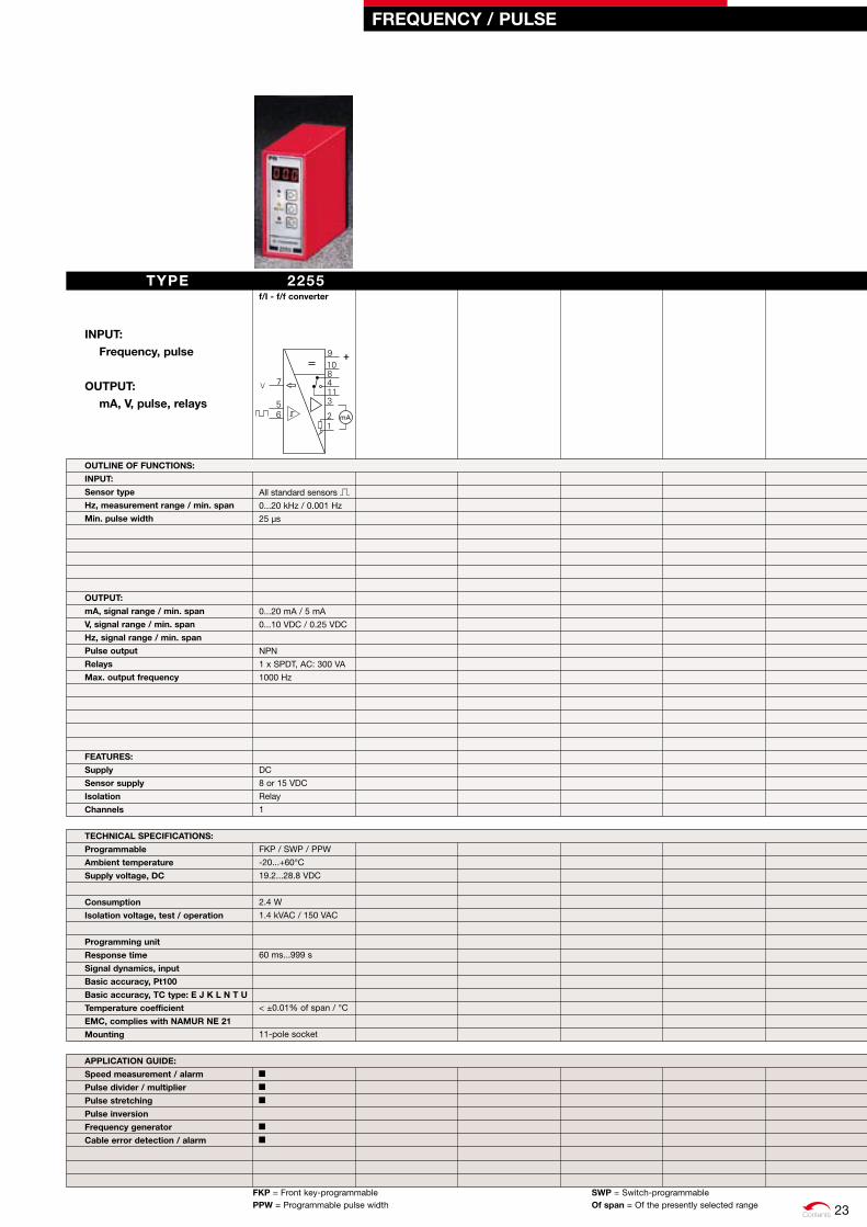
Contents
FrEQuENCY / PuLSE
FkP = Front key-programmable SWP = Switch-programmablePPW = Programmable pulse width of span = Of the presently selected range
TYPE INPuT:
Frequency, pulse
ouTPuT: mA, v, pulse, relays
ouTLINE oF FuNCTIoNS:
INPuT:
Sensor type
Hz, measurement range / min. span
Min. pulse width
ouTPuT:
mA, signal range / min. span
v, signal range / min. span
Hz, signal range / min. span
Pulse output
relays
Max. output frequency
FEATurES:
Supply
Sensor supply
Isolation
Channels
TECHNICAL SPECIFICATIoNS:
Programmable
Ambient temperature
Supply voltage, dC
Consumption
Isolation voltage, test / operation
Programming unit
response time
Signal dynamics, input
Basic accuracy, Pt100
Basic accuracy, TC type: E J k L N T u
Temperature coefficient
EMC, complies with NAMur NE 21
Mounting
APPLICATIoN GuIdE:
Speed measurement / alarm
Pulse divider / multiplier
Pulse stretching
Pulse inversion
Frequency generator
Cable error detection / alarm
2255f/I - f/f converter
All standard sensors
0...20 kHz / 0.001 Hz
25 µs
0...20 mA / 5 mA
0...10 VDC / 0.25 VDC
NPN
1 x SPDT, AC: 300 VA
1000 Hz
DC
8 or 15 VDC
Relay
1
FKP / SWP / PPW
-20...+60°C
19.2...28.8 VDC
2.4 W
1.4 kVAC / 150 VAC
60 ms...999 s
< ±0.01% of span / °C
11-pole socket
23
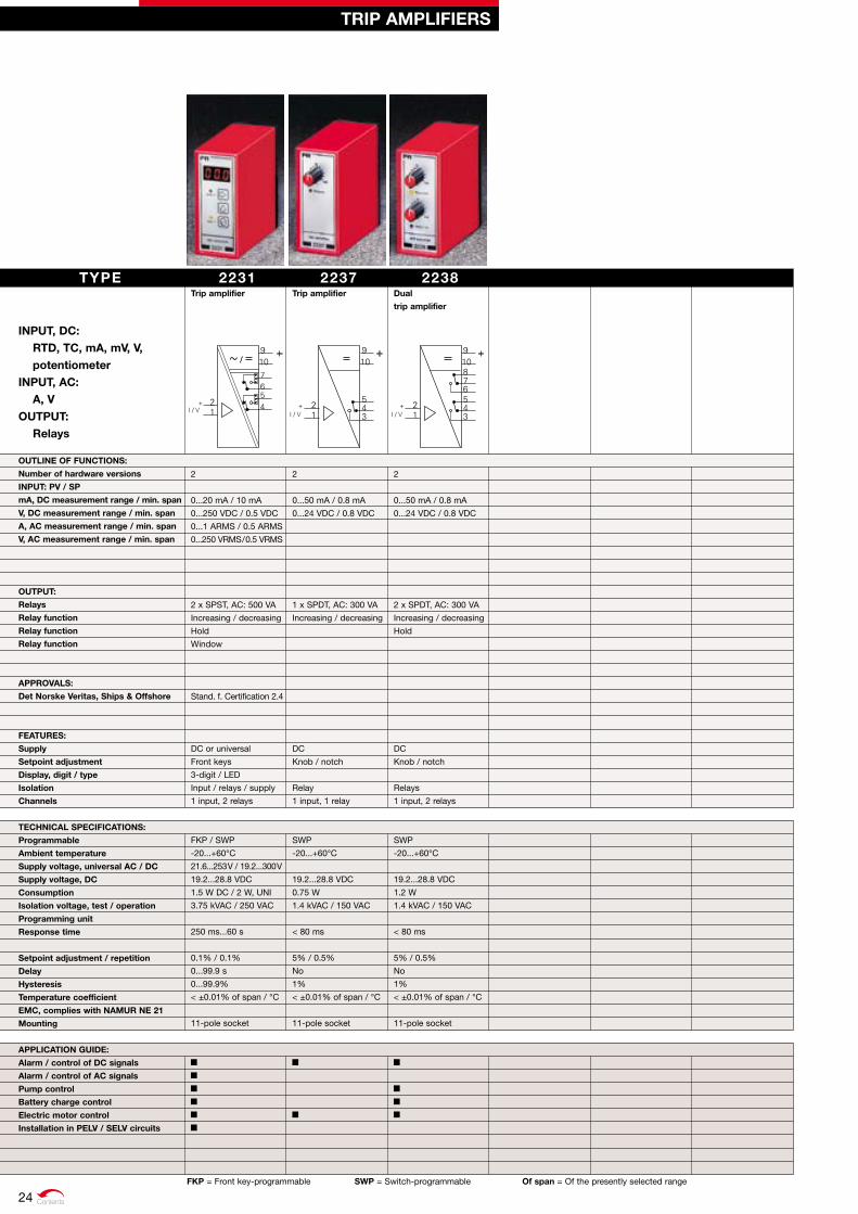
Contents
TrIP AMPLIFIErS
FkP = Front key-programmable SWP = Switch-programmable of span = Of the presently selected range
2231Trip amplifier
2
0...20 mA / 10 mA
0...250 VDC / 0.5 VDC
0...1 ARMS / 0.5 ARMS
0...250 VRMS / 0.5 VRMS
2 x SPST, AC: 500 VA
Increasing / decreasing
Hold
Window
Stand. f. Certification 2.4
DC or universal
Front keys
3-digit / LED
Input / relays / supply
1 input, 2 relays
FKP / SWP
-20...+60°C
21.6...253 V / 19.2...300 V
19.2...28.8 VDC
1.5 W DC / 2 W, UNI
3.75 kVAC / 250 VAC
250 ms...60 s
0.1% / 0.1%
0...99.9 s
0...99.9%
< ±0.01% of span / °C
11-pole socket
2237Trip amplifier
2
0...50 mA / 0.8 mA
0...24 VDC / 0.8 VDC
1 x SPDT, AC: 300 VA
Increasing / decreasing
DC
Knob / notch
Relay
1 input, 1 relay
SWP
-20...+60°C
19.2...28.8 VDC
0.75 W
1.4 kVAC / 150 VAC
< 80 ms
5% / 0.5%
No
1%
< ±0.01% of span / °C
11-pole socket
2238dual
trip amplifier
2
0...50 mA / 0.8 mA
0...24 VDC / 0.8 VDC
2 x SPDT, AC: 300 VA
Increasing / decreasing
Hold
DC
Knob / notch
Relays
1 input, 2 relays
SWP
-20...+60°C
19.2...28.8 VDC
1.2 W
1.4 kVAC / 150 VAC
< 80 ms
5% / 0.5%
No
1%
< ±0.01% of span / °C
11-pole socket
TYPE
INPuT, dC: rTd, TC, mA, mv, v, potentiometer
INPuT, AC: A, v
ouTPuT: relays
ouTLINE oF FuNCTIoNS:
Number of hardware versions
INPuT: Pv / SP
mA, dC measurement range / min. span
v, dC measurement range / min. span
A, AC measurement range / min. span
v, AC measurement range / min. span
ouTPuT:
relays
relay function
relay function
relay function
APProvALS:
det Norske veritas, Ships & offshore
FEATurES:
Supply
Setpoint adjustment
display, digit / type
Isolation
Channels
TECHNICAL SPECIFICATIoNS:
Programmable
Ambient temperature
Supply voltage, universal AC / dC
Supply voltage, dC
Consumption
Isolation voltage, test / operation
Programming unit
response time
Setpoint adjustment / repetition
delay
Hysteresis
Temperature coefficient
EMC, complies with NAMur NE 21
Mounting
APPLICATIoN GuIdE:
Alarm / control of dC signals
Alarm / control of AC signals
Pump control
Battery charge control
Electric motor control
Installation in PELv / SELv circuits
24
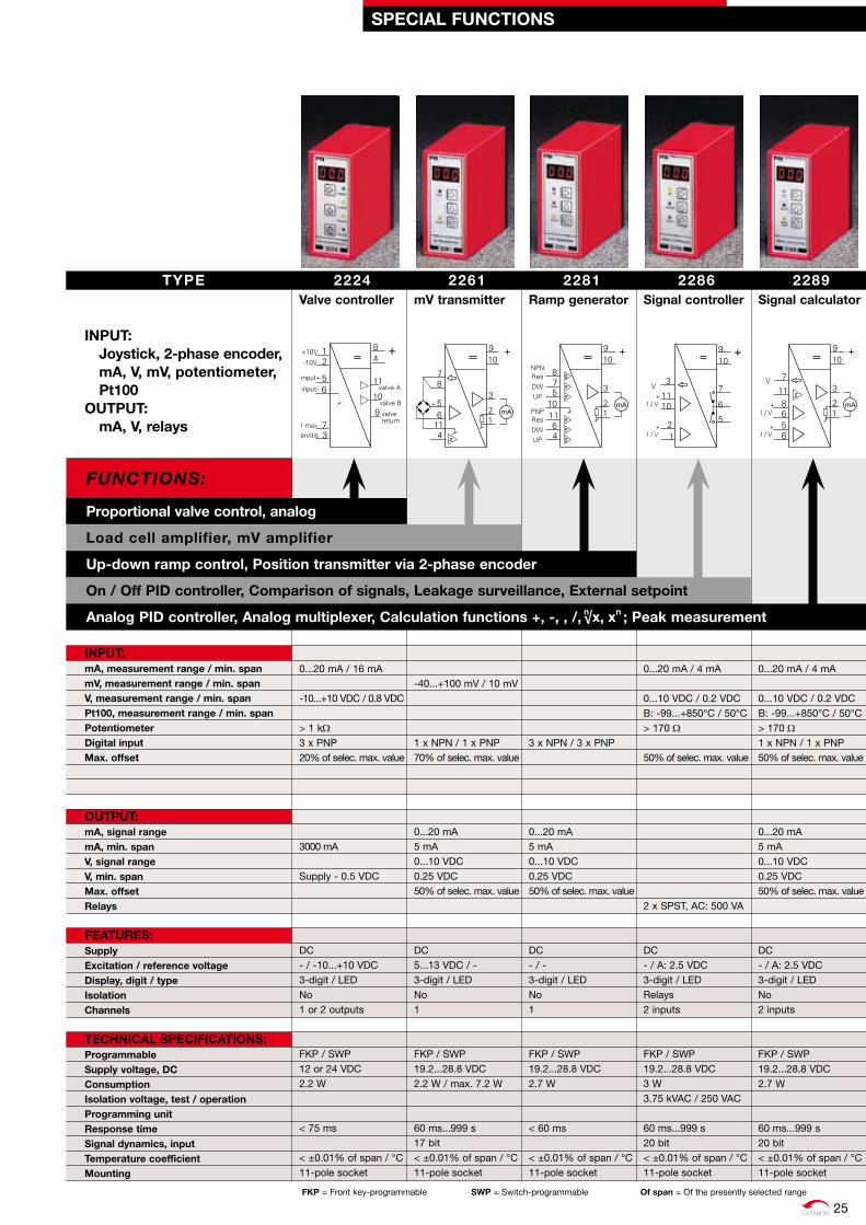
Contents
Proportional valve control, analog
Load cell amplifier, mv amplifier
up-down ramp control, Position transmitter via 2-phase encoder
on / off PId controller, Comparison of signals, Leakage surveillance, External setpoint
Functions:
Analog PId controller, Analog multiplexer, Calculation functions +, -, , /, ; Peak measurement
FkP = Front key-programmable SWP = Switch-programmable of span = Of the presently selected range
2224valve controller
0...20 mA / 16 mA -10...+10 VDC / 0.8 VDC > 1 kW3 x PNP 20% of selec. max. value 3000 mA Supply - 0.5 VDC DC - / -10...+10 VDC 3-digit / LED No 1 or 2 outputs FKP / SWP 12 or 24 VDC 2.2 W < 75 ms < ±0.01% of span / °C 11-pole socket
2261mv transmitter
-40...+100 mV / 10 mV 1 x NPN / 1 x PNP 70% of selec. max. value 0...20 mA 5 mA 0...10 VDC 0.25 VDC 50% of selec. max. value DC 5...13 VDC / - 3-digit / LED No 1 FKP / SWP 19.2...28.8 VDC 2.2 W / max. 7.2 W 60 ms...999 s 17 bit < ±0.01% of span / °C 11-pole socket
2281ramp generator
3 x NPN / 3 x PNP 0...20 mA 5 mA 0...10 VDC 0.25 VDC 50% of selec. max. value DC - / - 3-digit / LED No 1 FKP / SWP 19.2...28.8 VDC 2.7 W < 60 ms < ±0.01% of span / °C 11-pole socket
2286Signal controller
0...20 mA / 4 mA 0...10 VDC / 0.2 VDC B: -99...+850°C / 50°C > 170 W 50% of selec. max. value 2 x SPST, AC: 500 VA DC - / A: 2.5 VDC 3-digit / LED Relays 2 inputs FKP / SWP 19.2...28.8 VDC 3 W 3.75 kVAC / 250 VAC 60 ms...999 s 20 bit < ±0.01% of span / °C 11-pole socket
2289Signal calculator
0...20 mA / 4 mA 0...10 VDC / 0.2 VDC B: -99...+850°C / 50°C > 170 W1 x NPN / 1 x PNP 50% of selec. max. value 0...20 mA 5 mA 0...10 VDC 0.25 VDC 50% of selec. max. value DC - / A: 2.5 VDC 3-digit / LED No 2 inputs FKP / SWP 19.2...28.8 VDC 2.7 W 60 ms...999 s 20 bit < ±0.01% of span / °C 11-pole socket
TYPE
INPuT: Joystick, 2-phase encoder, mA, v, mv, potentiometer, Pt100
ouTPuT: mA, v, relays
INPuT:mA, measurement range / min. span mv, measurement range / min. span v, measurement range / min. span Pt100, measurement range / min. span Potentiometer digital input Max. offset
ouTPuT: mA, signal range mA, min. span v, signal range v, min. span Max. offset relays
FEATurES:Supply Excitation / reference voltage display, digit / type Isolation Channels TECHNICAL SPECIFICATIoNS:Programmable Supply voltage, dC Consumption Isolation voltage, test / operation Programming unit response time Signal dynamics, input Temperature coefficient Mounting
SPECIAL FuNCTIoNS
√x, xnn
25

Contents
PoWEr SuPPLIES
2220Switchmode
power supply
4
24 VAC ±10%
110 VAC ±10%
120 VAC ±10%
230 VAC ±10%
5...24 VDC ±5%
1 A / 5 VDC
0.55 A / 12 VDC
0.45 A / 15 VDC
0.30 A / 24 VDC
7 W
No
Supply / output
1
IPo
-20...+60°C
4 W
3.75 kVAC / 250 VAC
No
2.2 A
100°C
< 20 mVRMS
< ±30 mVDC
< 1.5% / A
0.05% / °C
80.5 x 35.5 x 84.5 mm
425 g
11-pole socket
2222Switchmode
power supply
4
115 VAC +15%, -11%
230 VAC ±10%
24 VDC ±5%
15 VDC ±5%
2 A / 15 VDC
2 A / 24 VDC
48 W
No
Supply / output
1
No
-20...+60°C
12 W
3.75 kVAC / 250 VAC
0.48 W / °C > 40°C
2.5 A
100°C
< 40 mVRMS
< 1%
< 1.5% / A
0.05% / °C
80.5 x 35.5 x 84.5 mm
210 g
11-pole socket
2240Transformer
4
115 VAC ±15%
230 VAC ±10%
24 VAC
12 VAC
2.5 A / 12 VAC
1.25 A / 24 VAC
30 VA
No
Supply / output
1
No
-20...+60°C
3.75 kVAC / 250 VAC
0.4 VA / °C > 25°C
No
100°C
80.5 x 35.5 x 84.5 mm
600 g
11-pole socket
2229Switchmode
voltage regulator
1
28 VAC max.
Min. AC: (Vout. + 5)/1.2
40 VDC max.
Min. DC: (Vout. + 5)
5...24 VDC ±10%
2.5 A / 5 VDC
2.5 A / 12 VDC
2.5 A / 15 VDC
1.7 A / 24 VDC
40 W
Via potentiometer
No
1
IPo / EPo
-20...+60°C
10 W
No
No
5.8 A
< 20 mVRMS
< ±30 mVDC
< 1.5% / A
0.05% / °C
80.5 x 35.5 x 84.5 mm
170 g
11-pole socket
2223dual switchmode
power supply
3
24 VAC ±10%
115 VAC ±10%
230 VAC ±10%
2 x 5...24 VDC ±10%
0.5 A / 5 VDC
0.37 A / 12 VDC
0.30 A / 15 VDC
0.18 A / 24 VDC
7.5 W
No
Supply / output
2
IPo
-20...+60°C
4 W
3.75 kVAC / 250 VAC
No
1.5 A
100°C
< 20 mVRMS
< ±30 mVDC
< 1.5% / A
0.05% / °C
80.5 x 35.5 x 84.5 mm
400 g
11-pole socket
IPo = Internal potentiometer EPo = External potentiometer
TYPE INPuT:
AC, dC voltageouTPuT:
Stabilized vdC Transformer AC
ouTLINE oF FuNCTIoNS:
Number of hardware versions
INPuT:
Supply voltage, AC 50...60 Hz
ouTPuT:
voltage
Current
Power, max.
FEATurES:
External voltage adjustment
Isolation
Channels
TECHNICAL SPECIFICATIoNS:
Programmable
Ambient temperature
Internal consumption
Isolation, test / operation
Power reduction
Short circuit protection
Thermal fuse
output ripple
Stability error: supply ±10%
Stability error: load 0...100%
Temperature coefficient
dimensions (HxWxd)
Weight
Mounting
APPLICATIoN GuIdE:
Mains connection
dC connection
Fixed output
Adjustable output
External adjustable output
AC / AC transformer
General dC supply
Installation in PELv / SELv circuits
26
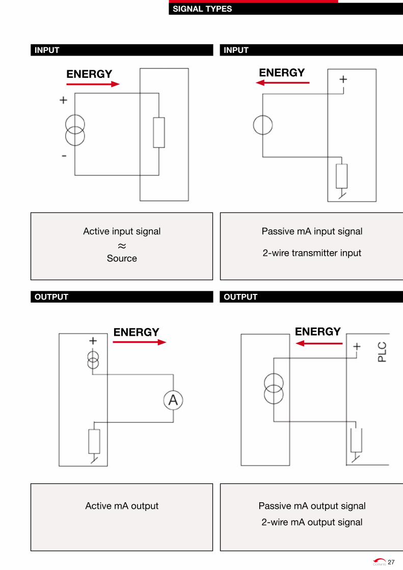
Contents
SIGNAL TYPES
INPuT INPuT
ouTPuT ouTPuT
Active input signal
≈Source
Passive mA input signal
2-wire transmitter input
Active mA output Passive mA output signal
2-wire mA output signal
ENErGYENErGY
ENErGY ENErGY
27
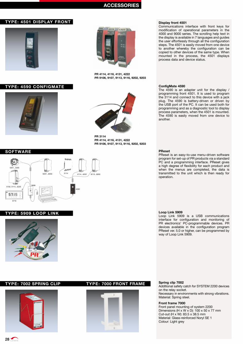
File Product Input Output Communication Language Option 08:30:00
PRetop 5331
Date: 1994-8-10
943201594
PRelectronics
Analog inputAnalog output
Serial no:
Input type:Output type: 4 - 20mA
UpscaleSensor error:
Pt100 DIN/IEC
0.00 - 50.00 C
3-w ire
1.00 sec------
Input range:
Connection:
Cold junction comp:
Response time:
Tag no:
5715
5331...5335
5102, 5114...5225
6331...6335 4114...42223114 9113...9203
4590
5909
11 131211 131211 1312
CH 2
CH 1
23 23
41 4342 4454
41 4342 4454
41 4342 4454
41 4342 4451
11 131221
23
COM
Loop Link
1 2 3 4
OK
Pr 4114, 4116, 4131, 4222 Pr 9106, 9107, 9113, 9116, 9202, 9203
Pr 3114 Pr 4114, 4116, 4131, 4222 Pr 9106, 9107, 9113, 9116, 9202, 9203
Contents
ACCESSorIES
TYPE: 4501 dISPLAY FroNT
TYPE: 4590 CoNFIGMATE
display front 4501Communications interface with front keys for modification of operational parameters in the 4000 and 9000 series. The scrolling help text in the display is available in 7 languages and guides the user effortlessly through all the configuration steps. The 4501 is easily moved from one device to another whereby the configuration can be copied to other devices of the same type. When mounted in the process, the 4501 displays process data and device status.
ConfigMate 4590The 4590 is an adapter unit for the display / programming front 4501. It is used to program the 3114 and connect to this device with a jack plug. The 4590 is battery-driven or driven by the USB port of the PC. It can be used both for programming and as a diagnostic tool to display process parameters, when the 4501 is mounted. The 4590 is easily moved from one device to another.
PresetPReset is an easy-to-use menu-driven software program for set-up of PR products via a standard PC and a programming interface. PReset gives a high degree of flexibility for each product and when the menus are completed, the data is transmitted to the unit which is then ready for operation.
Loop Link 5909Loop Link 5909 is a USB communications interface for configuration and monitoring of PR electronics’ PC-programmable devices. PR devices available in the configuration program PReset ver. 5.0 or higher, can be programmed by way of Loop Link 5909.
Spring clip 7002Additional safety catch for SYSTEM 2200 devices on the relay socket.Necessary in environments with strong vibrations. Material: Spring steel.
Front frame 7000Front panel mounting of system 2200Dimensions (H x W x D): 100 x 50 x 77 mmCut-out (H x W): 83.5 x 38.5 mmMaterial: Glass-reinforced Noryl SE 1Colour: Light grey
TYPE: 7002 SPrING CLIP TYPE: 7000 FroNT FrAME
TYPE: 5909 LooP LINk
SoFTWArE
2828
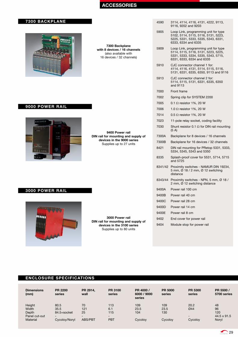
Contents
ACCESSorIES
4590 3114, 4114, 4116, 4131, 4222, 9113, 9116, 9202 and 9203
5905 Loop Link, programming unit for type 5102, 5114, 5115, 5116, 5131, 5223, 5225, 5331, 5333, 5335, 5343, 6331, 6333, 6334 and 6335
5909 Loop Link, programming unit for type 5114, 5115, 5116, 5131, 5223, 5225, 5331, 5333, 5334, 5335, 5343, 5715, 6331, 6333, 6334 and 6335
5910 CJC connector channel 1 for: 4114, 4116, 4131, 5114, 5115, 5116, 5131, 6331, 6335, 6350, 9113 and 9116
5913 CJC connector channel 2 for: 5114, 5115, 5131, 6331, 6335, 6350 and 9113
7000 Front frame
7002 Spring clip for SYSTEM 2200
7005 0.1 W resistor 1%, 20 W
7006 1.0 W resistor 1%, 20 W
7014 0.5 W resistor 1%, 20 W
7023 11-pole relay socket, coding facility
7030 Shunt resistor 0.1 W for DIN rail mounting (5 A)
7300A Backplane for 8 devices / 16 channels
7300B Backplane for 16 devices / 32 channels
8421 DIN rail mounting for PRetop 5331, 5333, 5334, 5345, 5343 and 5350
8335 Splash-proof cover for 5531, 5714, 5715 and 5725
8341/42 Proximity switches - NAMUR DIN 19234, 5 mm, Ø 18 / 2 mm, Ø 12 switching distance
8343/44 Proximity switches - NPN, 5 mm, Ø 18 / 2 mm, Ø 12 switching distance
9400A Power rail 100 cm
9400B Power rail 40 cm
9400C Power rail 28 cm
9400D Power rail 14 cm
9400E Power rail 8 cm
9402 End cover for power rail
9404 Module stop for power rail
9400 Power rail dIN rail for mounting and supply of
devices in the 9000 seriesSupplies up to 27 units
ENCLoSurE SPECIFICATIoNS
7300 BACkPLANE
7300 Backplane with 8 devices / 16 channels
(also available with 16 devices / 32 channels)
3000 PoWEr rAIL
3000 Power rail dIN rail for mounting and supply of
devices in the 3100 seriesSupplies up to 80 units
9000 PoWEr rAIL
dimensions (mm)
Height Width Depth Panel cut-out Material
Pr 2200 series
80.5 35.5 84.5+socket - Cycoloy/Noryl
Pr 2914, wall
70 121 25 - ABS/PBT
Pr 3100 series
113 6.1 115 - PBT
Pr 4000 / 6000 / 9000 series
109 23.5 104 Cycoloy
Pr 5000 series
109 23.5 130 Cycoloy
Pr 5300 series
20.2 Ø44 - Cycoloy
Pr 5500 / 5700 series
48 96 120 44.5 x 91.5 Noryl
29
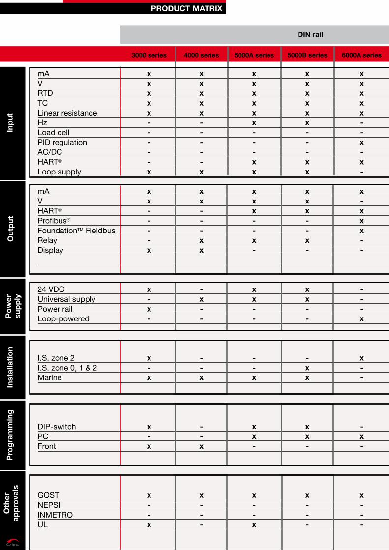
Contents
mAVRTDTCLinear resistanceHzLoad cellPID regulationAC/DCHART
Loop supply
mAVHART
Profibus
Foundation FieldbusRelayDisplay
24 VDCUniversal supplyPower railLoop-powered
I.S. zone 2I.S. zone 0, 1 & 2Marine
DIP-switchPCFront
GOSTNEPSIINMETROUL
Inp
uto
utp
utP
ow
er
sup
ply
Inst
alla
tio
no
ther
ap
pro
vals
Pro
gra
mm
ing
ProduCT MATrIX
3000 series 4000 series 5000A series 5000B series 6000A series
dIN rail
xxxxx-----x
xx----x
x-x-
x-x
x-x
x--x
xxxxx-----x
xx---xx
-x--
--x
--x
x---
xxxxxx---xx
xxx--x-
xx--
--x
xx-
x--x
xxxxxx---xx
xxx--x-
xx--
-xx
xx-
x---
xxxxx--x-x-
x-xxx--
---x
x--
-x-
x---
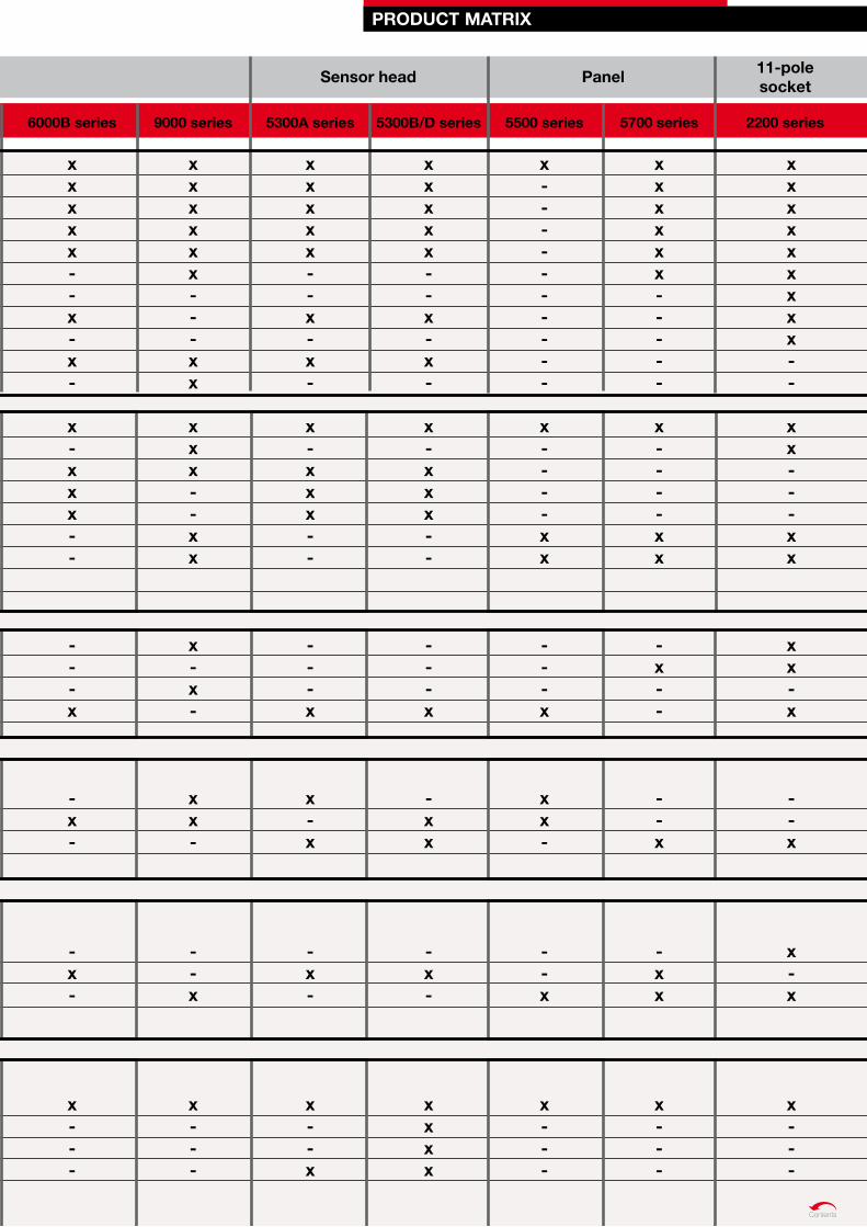
Contents
6000B series 9000 series 5300A series 5300B/d series 5500 series 5700 series
ProduCT MATrIX
dIN rail Sensor head Panel 11-pole socket
2200 series
xxxxx--x-x-
x-xxx--
---x
-x-
-x-
x---
xxxxxx---xx
xxx--xx
x-x-
xx-
--x
x---
xxxxx--x-x-
x-xxx--
---x
x-x
-x-
x--x
xxxxx--x-x-
x-xxx--
---x
-xx
-x-
xxxx
x----------
x----xx
---x
xx-
--x
x---
xxxxxx-----
x----xx
-x--
--x
-xx
x---
xxxxxxxxx--
xx---xx
xx-x
--x
x-x
x---

Signals the Best
Around the world, PR electronics helps
create increased efficiency and safety via
industrial signal conditioning. The means
to achieve this is reliable, flexible and
user-friendly devices, thorough technical
documentation, fast delivery and competent
technical support – in short, all aspects
which are of importance to our customers.
This is why PR electronics always...
»Signals the Best«
1015W11U
S(1131)
Head officeDenmark PR electronics A/S Lerbakken 10 DK-8410 Rønde
[email protected]. +45 86 37 26 77fax +45 86 37 30 85
uSAPR electronics Inc11225 West Bernardo CourtSuite A San Diego, California 92127
www.prelectronics.com [email protected] tel. +1 858 521 0167Fax +1 858 521 0945