Product guide - Intelligent Infrastructure - Topic Areas -...
12
Product guide ACCESS power analysis metering Answers for industry. 9340/9360 meters P P Pr r ro o o o o od d d d d du u u u u uc c c c c ct t t t t t g g g g g gu u u u u ui i i i i id d d d d de e e e e e ACCESS power analysis metering
Transcript of Product guide - Intelligent Infrastructure - Topic Areas -...

Product guide
ACCESS power analysis metering
Answers for industry.
9340/9360 meters
PPPrrroooooodddddduuuuuucccccctttttt gggggguuuuuuiiiiiiddddddeeeeee
ACCESS power analysis metering
Compact power, energy and power quality metersThe Siemens ACCESS 9340/9360 series power meters combineaccurate, 3-phase energy and power measurement with data logging, power quality analysis, alarm and I/O capabilities nottypically available in a compact meter. The meters are ideallysuited to local and remote monitoring of low or high voltageelectrical installations in industrial facilities, commercial buildings, utility networks or critical power environments. Facility and operations personnel will benefit in energy-related costs while avoiding power quality conditions that can reduce equipment life and productivity.
ACCESS 9340/9360 series meters are easy to install and use, offering integrated or remote high-visibility displays. A choice of two models and a range of expansion modules help match features to the application and support field-upgrading of metersas required. Serial and Ethernet communication options enablethe meters to be used within a WinPM.Net power managementsystem or with third-party automation systems.
Typical applicationsIndustrial, commercial, and critical powern Energy savings - Measure efficiency, reveal opportunities and verify savings - Sub-bill tenants for energy costs - Allocate energy costs to departments or processes - Reduce peak demand surcharges - Reduce power factor penalties - Leverage existing infrastructure capacity and avoid over-building - Support proactive maintenance to prolong asset lifen Energy availability and reliability - Validate that power quality complies with the energy contract - Verify the reliable operation of equipment - Improve response to power quality-related problems
For electrical infrastructuren Energy availability and reliability - Improve transmission and distribution network reliability - Enhance substation metering to reduce field service time - Maximize the use of existing infrastructuren Power quality - Verify compliance with new power quality standards - Analyze and isolate the source of power quality problems
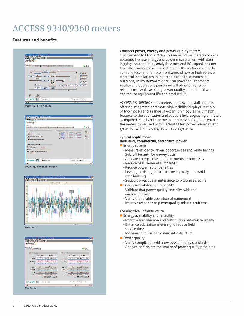
Main real time values
Power quality main screen
Waveforms
Min /max
ACCESS 9340/9360 metersFeatures and benefits
9340/9360 Product Guide2

Cost-effective, modular designStandard features include a range of 3-phase power and energymeasurements, total harmonic distortion (THD) metering, one RS-485 Modbus communication port, one digital input, one KY-type digital output, and alarming on critical conditions. A choice of two models offers incremental levels of custom logging and power quality analysis capabilities, while expansion modulesoffer additional logging, I/O and ethernet connectivity.
Easy installationMounts into panel cutouts using two clips with no tools required.Direct connect to circuits up to 600 VAC, eliminating the need forvoltage (potential) transformers.
High-visibility displayIntegrated or remote LCD offers multi-phase measurements, summary screens, bar charts, intuitive navigation and selectable languages.
High accuracy measurementsIEC 62053-22 class 0.5S and ANSI C12.20 0.5S energy accuracy for sub-billing and cost allocation.
Power quality analysisA choice of THD metering, individual current and voltage harmonics readings, waveform capture, EN50160 power quality
compliance evaluation, and voltage and current disturbance(sag/swell) detection.
Extensive data logging, trending and forecastingNon-volatile on-board logging of min/max values, energy and demand, maintenance data, alarms, and any measured parameters.Trending and short-term forecasting of energy and demand.
Custom alarming with time stampingTrigger alarms on over 50 definable power or I/O conditions. Use boolean logic to combine up to four alarms.
Expandable I/OA wide choice of standard or optional digital and analog inputs and outputs for pulse counting, demand metering for other utilities(pulse inputs from water, air, gas electricity or steam meters),equipment status/position monitoring, demand synchronization,triggering conditional energy metering, equipment control or interfacing.
Multi-port serial and ethernet communicationsUp to three si multaneous Modbus communication ports. Use theRS-485 port on the base meter unit or the optional Ethernet portthat offers e-mail on alarm, web server and an Ethernet-to-serialRS485 gateway. The remote display adaptor option offers an additional RS-485/RS-232 port.
Power generation transmission and distribution
Service entrances and onsite generation
Power mitigation andmain power distributionequipment
PDUs and data servers Tenants, departments or subcontractors
Processes, lines, machines or equipment
Supports operations management planningand procedures
Financial management including accounting and billing
Facility and energy management
Typical applications of 9340/9360 meters within an ACCESS power and energy management system
DIN-rail mounted meter with remote display option, including adaptor, cable and displayPanel-mount meter with integrated display
ACCESS 9340/9360 metersFeatures
9340/9360 Product Guide 3

Installation – Mounting optionsA meter with integrated display, or a remote display module, can be panel mounted through a square cutout or retrofit through an existing round meter hole using two clips with no tools required. A small panel footprint and shallow depth make the meters suitablefor low voltage switchboards, shallow cable compartments or on standalone machines. The meter unit (without display) is DIN rail compatible.
Meters with the optional integrated display can be door panelmounted when voltage connections are within the local regulationlimits. When voltage exceeds regulation limits, the meter unit can be mounted inside the electrical cabinet with an optional remote display connecting via a display adaptor and cable. The display adaptor includes a configurable 2- or 4-wire RS-485/RS-232 port.A single remote display can be transferred between any meter units equipped with display adaptors.
Circuit and control power connectionsCompatible with low and high voltage 4-wire wye and 3-wire deltasystems. Direct connect inputs up to 600 V AC line-to-line or use voltage (potential) transformers for higher voltage systems. All models offer a universal AC or DC power supply.
Front panel display The unique, anti-glare backlit white LCD can be easily read in extreme lighting conditions or viewing angles. An intuitive navigation with self-guided menus make the meter easy to use. Multilingual operation can be user-configured for English, French,Spanish, German or Portuguese.
The large 6-line display offers summary screens that simultaneouslypresents up to 4 concurrent values, including power and energy values, I/O conditions or alarm status. For example, all three voltage or current phases plus neutral can be quickly reviewed at one time. Bar chart displays graphically represent system loading and I/O conditions. Historical and active alarms are displayed withtime stamping.
A.Meter with integrated display panel mounted into square cutout.B. Meter with integrated display retrofit into existing 4” round meter cutout.C. Meter unit side view showing mounting depth with and without option modules.
D.DIN rail mounted meter unit with optional remote display package, including display adaptor module, display cable and display module. Three cable length options are available.
Front panel display showing function selection buttons and 3-phase voltage, current and power summary display
(92 mm +0.8 –0.0)
3.62 in.
(92 mm +0.8 –0.0) 3.62 in.
(96 mm)3.78 in.
2.73 in. (69.4 mm)
(90.5 mm) 3.56 in.
(20 mm) 0.78 in.
(17.8 mm) 0.70 in.
3.64 m / 9.14 m 12 ft. / 30 ft.)
(A)
(B)
(C)
(D)
(96 mm)3.78 in.
Input(s) Specifications
Voltage inputs Nominal full scale (Un) 347 direct V AC line-to-neutral, 600 V AC direct line-to-line, up to 3.2 MV with external VT/PT Metering over-range 1.5 Un (50%) Input impedance 5 M Ω Frequency range 45 to 67 Hz, 350 to 450 Hz Current inputsNominal current 1 A or 5 A aCMetering range 5 mA to 10 A aCWithstand 15 A continuous, 50 A for 10 s per hour, 500 A for 1 s per hourLoad/burden < 0.15 VAImpedance < 0.1Ω Control powerOperating range 115 to 415 V AC ±10% at 45 to 67 Hz or 350 to 450 Hz 125 to 250 V DC ±20%Load/burden 15 VA (AC) or 10 W (DC) with all optionsRide through 45 ms at 120 V AC or 125 V DC
ACCESS 9340/9360 metersInstallation
4 9340/9360 Product Guide

1) Selectable block, sliding, or thermal demand calculation mode with internal or external (via digital input) demand synchronization.2) Configurable accumulation mode, triggerable from digital input.3) Full scale = 10 A. Add 0.006% to upper limit error for operating temperatures under 25°C.4) Full scale = 600 V. Add 0.001% to upper limit error for operating temperatures over 50°C.5) Full scale = 120 V x 10 A. Add 0.006% to upper limit error for operating temperatures under 25°C.
Power and energy measurementsMetering is performed by zero-blind sampling all inputs at 128 samples/cycle with a data update rate of 1 second. The meter offers a range of high-accuracy instantaneous RMS, power, demand and energy measurements suitable for real-time monitoring, energy management and sub-billing purposes.
Power quality analysisA choice of models offers an incremental range of measurement and event capture features for troubleshooting and preventing power quality related problems.
nBasic THD (both models): on voltage and current, per phase, min/max, custom alarming (see Alarm section).
n Individual harmonic magnitudes and angles: on voltage and current, up to the 31st harmonic for the 9340, up to the 63rd for 9360.
nWaveform capture (9360): triggered manually or by alarm, 3-cycle, 128 samples/cycle on 6 user configurable channels, manual or alarm-triggered initiation.
nConfigurable waveform capture (9360): flexible resolution permits you to adapt the waveform captures according to the type of event/ disturbance on selected channels, from 185 cycles on 1 channel at 16 samples per cycle up to 3 cycles on 6 channels at 128 samples per cycle.
nEN50160 standard compliance evaluation (9360): pass/fail indication on power frequency, supply voltage magnitude, supply voltage dips, short and long interruptions, temporary overvoltages, voltage unbalance and harmonic voltage.
nDisturbance detection (9360): sag/swell on any current and voltage channel, alarm on disturbances.
Use WinPM.Net 3.2, SP1 or greater software to upload and graphicallyplot waveforms to help analyze conditions and isolate problems.
Measurement Accuracy
Current: per phase, ± (0.075% reading + 0.025% full scale) 3)
neutral, min/max Current demand: present, peak, predicted 1)
Voltage ± (0.075% reading scale) 4)
(line-line, line-neutral): per phase, min/max, unbalance
Power: real (kW), ± (0.15% reading + 0.025% full scale 5)
reactive (kVAr), apparent (kVA), per-phase, total
Power demand: present, peak, predicted1)
Energy: real (kWh), IEC 62053-22 0.5S (real), reactive (kVArh), IEC 62053-23 Class 2 (reactive), apparent (kVAh), in/out 2) ANSI C12.20 0.5S
Power factor: true ± 0.002 to 0.500 leading andand displacement, ± 0.002 to 0.500 laggingper phase, total, min/max
Frequency: present, ±0.01 Hz at 45 to 67 Hz,min/max ±0.01 Hz at 350 to 450 Hz
3-phase and neutral current Energy in, out, and total display
Current total harmonic distortion display
Alarm display showing active alarm
Peak power demand date/time display Digital inputs display
ACCESS 9340/9360 metersMeasurements
59340/9360 Product Guide

1) Endurance: 15 million operations, 25000 communications at 2A / 250 V AC.2) When using two 9340-60-I/O2222 modules, the temperature should not exceed 25ºC / 77º F.
Attachment of logging, I/O, or Ethernet expansion modules to meter unit
Data and event loggingData is stored in on-board nonvolatile memory, increasing the reliability of critical information used for billing and troubleshooting by eliminating data gaps that can occur due to network outages or computer server downtime.
nMinimum/maximum log: for all instantaneous readings, logs worst phase since last reset, including date and time stamp.nMaintenance log (both models): records date and time of energy, I/O and demand resets, firmware updates, power failures and option module changes.n Alarm log (both models): records all user-defined alarm conditions with date/time stamping to 1 second resolution.n Billing log and energy per interval: logs kWh in and total, kVARh in and total, kVAh total, PF total, kW and kVar demand. Logging interval is user-configurable from five-- minutes to one day. Energy per-interval log tracks usage and cost for up to three user-definable shifts per day.n Customizable data logs: One on 9340, three on 9360. Each log can record up to 96 user-definable parameters.n Trend logging and forecasting (9360): trending for energy and demand average, minimum and maximum values by four trend curves. Min/max and average data available for each quantity at intervals of minutes, hours, days and months. Forecasting feature “looks into the future” by automatically forecasting average, minimum and maximum for the next four hours and next four days. Statistical summaries available for hours and weeks.
Logging capacity is 80 kB for 9340, and 800kB for 9360. All models provide a battery-backed internal clock. Default logging is set at the factory, logging starts as soon as meter is powered up.
Digital and analog inputs and outputsAll models provide a single digital status/counter input and digital (KY type) output. A wide range of optional field-installable expansion modules will add more digital and analog I/O as required. Up to two expansion modules can be installed per meter (including logging or communication modules).
Digital output relays can act in response to internal alarms, external digital input status changes, or commands over communications. Digital inputs can be used to triggeralarms, trigger logging, synchronize to a demand pulse or control conditional energy accumulation. Both models offer five channels for metering of water, air, gas, electricityor steam utilities through the digital input pulse counting and consumption/ demand calculation capabilities of the meter. Pulses from multiple inputs can be summed through a single channel.
Bottom view of 9340-60-ETHER communications module and main meter unit, showingEthernet and RS-485 communication port connectors and configuration switches
Type Input/ Output SpecificationsStandard 1 digital KY 6 to 220 V AC ±10 % or 3 to 250 V DC ±10 %,(Meter 100 mA maximum at 25 °C, 1350 V rms isolationUnit) 1 digital 20 to 150 V AC/DC ±10 %, input <5 mA maximum burden9340-60- 2 digital 6 to 240 V ac or 6 to 30 V DC, 2 A rms,I/026 relay 5 A maximum for 10 seconds/hour outputs 1)
6 digital 20 to 150 V AC/DC, 2 mA max., inputs 24 V internal supply: 20 to 34 V DC, 10 mA maximum (feeds 6 inputs)9340-60- 2 digital 6 to 240 V AC or 6 to 30 V DC, 2 A rms,I/O22222) relay 5 A maximum for 10 seconds/hour outputs1)
2 digital 20 to 150 V AC/DC, 2 mA maximum inputs 2 analog 4 to 20 mA DC into 600 Ωmaximum outputs 2 analog Adjustable from 0 to 5 V DC or 4-20 mA DC inputs
ACCESS 9340/9360 metersData and events logging
6 9340/9360 Product Guide

Alarm and control functionsOver 50 definable alarm conditions with 1 second response time canbe used to log critical events or to perform control functions. Triggeron over or under conditions on any measured parameters, phaseunbalance, digital input changes and more.
Multiple alarms can be defined, with each alarm individuallyconfigured with pickup setpoint, dropout setpoint and delay. Each alarm can be assigned one of four priority classes. Assign multiple alarms to a single quantity to create alarm levels. Assign different actions based on the severity level of the alarm. Use alarms to trigger waveform recording, data logging or to control digital outputs.
Boolean alarm logic with the ACCESS 9360 meter increases flexibility by allowing the combination of up to four other alarmsusing NAND, AND, OR, NOR and XOR functions.
CommunicationsMultiple simultaneously operating communication ports allow the meters to be used as part of a power and energy management system and interface with other automation systems. Captured waveforms, alarms, billing data, and more can be uploaded toWinPM.Net 3.2 for viewing and analysis. Option modules offer achoice of communications standards.
n Standard RS-485 port (on meter unit): 2-wire connection, up to 38.4 kbaud, Modbus (ASCII and RTU) or JBUS protocol.
n 9340-60-DISPADA display adaptor module: offers a second RS-485/232 port, 2- or 4-wire, Modbus (ASCII and RTU). Port is disabled if a 9340-60-ETHER module is installed.
n 9340-60-ETHER Ethernet module: 10/100 Base-T UTP port supporting ModbusTCP/IP communications. Full-function embedded web server provides standard web browser access to meter data, and the ability to email on an alarm from the host meter. RS-485/232 port, 2- or 4-wire, Modbus (ASCII and RTU) master port providing Ethernet-to-serial line gateway functionality.
Software integrationIntegration with the WinPM.Net system software allows for automatic retrieval of the meters real-time and on-board data logs.Modbus compatibility and register-based logged data supports integration and data access by building automation, SCADA andother third-party systems.
Example screen from WinPM.Net software showing electrical system diagram with multiple real-time metering points.
Special featuresHour counter: load running time in days, hours and minutes.
Upgradeable Firmware – Your meters can be upgraded with the latest firmware. Contact your local Siemens representative for details.
Description Specification
Weight No options, no display: 0.5 kg (1.1 lb.) With integrated display 0.6 kg (1.3 lb.)Safety Europe: C E as per IEC 61010-1 protected throughout by double insulation. US and Canada: UL508, cUL508Operating temp. Meter: -25 °C to +70 °C. Display: -10 °C to +50 °C. Derating may apply with remote display or multiple option modules, see installation manual.Storage temp. -40 °C to +85 °CRelative humidity 5 to 95% at 40 °C (non-condensing)Altitude 3000 m maximumPollution degree 2Installation category III, for distribution systems up to 347 V ac line-to-neutral / 600 V AC line-to-lineDielectric withstand As per EN 61010, UL508IP degree of protection As per IEC 60529: IP52 front display, IP30 meter bodyImmunity ESD: IEC 61000-4-2 Level 3, Radiated: IEC 61000-4-3 Level 3, Fast transients: IEC 61000-4-4 Level 3, Impulse waves: IEC 61000-4-5 Level 3. Conducted: IEC 61000-4-6 Level 3, Magnetic field: IEC 61000-4-8 Level 3, Voltage dips: IEC 61000-4-11Emissions Conducted and radiated: e industrial environment / FCC part 15 class A EN 55011, Harmonics: IEC 61000-3-2, Flicker: IEC 61000-3-3
ACCESS 9340/9360 metersFunctions
7 9340/9360 Product Guide

Description 9340 9360
General selection criteria Power quality measurement Total harmonic distortion Phases n n Neutral n n Voltage per phase (L-L, L-N) n n Frequency n n Total power Active n n Reactive n n Apparent n n Power per phase Active n n Reactive n n Apparent n n Power factor Total n n Per phase n n Energy values Real energy n n Apparent energy n n User-set accumulation mode n n Demand values Current Present and max. values n n Total active power Present and max. values n n Total reactive power Present and max. values n n Total apparent power Present and max. values n n Total predicted demand kW, kVAR, kVA n n Synchronization of calculation window n n User-set calculation mode n n Power quality measurements Total harmonic distortion Voltage n n Current n n Individual harmonic magnitude and angles 31 63 Waveform capture — up to 185 cycles Detection of voltage sags and swells — n Programmable (logic and mathematical functions) — n EN50160 compliance checking — n True ms measurement Max. harmonic number 63 63 Sampling rate Points per cycle 128 128 Logging
Min/max of instantaneous values n n Data logging n n Event logging n n Trend curves — n Alarms n n Storage capacity 80 kB 800 kB Display, sensors, input/outputs Front panel display n n Pulse output n n Digital or analog inputs (max. number) 13 13 Digital or analog outputs (max. number, including pulse outputs) 9 9 Direct voltage connections without eternal V 600V 600V Input metering capability: number of channels 5 5
ACCESS 9340/9360 metersProducts selection guide
8 9340/9360 Product Guide

Specifications (based on 50/60 Hz nominal systems)
1) Full scale=10A. Add 0.006% (Temperature [ºC] -25 to the upper limit error for temperatures below 25ºC.2) Full scale=600V. Add 0.001% (Temperature [ºC] -25 to the upper limit error for temperatures below 25ºC.3) Full scale=620V x 10A. Add 0.006% (Temperature [ºC] -25 to the upper limit error for temperatures below 25ºC.4) Requires 5ºC derating when using display and control power above 305V.5) Derate load current 0.56 mA/ºC above 25ºC.
Technical specifications Current inputs (each channel)
Nominal current 5 A ac Metering range 0-10 A ac
Withstand 15 A continuous
50 A 10 sec per hour
500 A 1 sec per hour
Burden Less than 0.15 VA
Input impedance Less than 0.1 Ohm
Voltage inputs (each channel)
Nominal full scale 347 Vac L-N 600 Vac L-L
Metering over-range 50%
Input impedance 5 Mohm
Metering frequency range 45–67 Hz, 350–450 Hz
Metering category III
Accuracy
IEC 62053-22 0. .5S (real energy)
ANSI C12 .20 0. .5S
Current
± [0. .075% reading + 0. .025% full scale]1)
Voltage
± [0. .075% reading + 0. .025% full scale] 2)
Power
± [0. .15% reading + 0. .025% full scale] 3)
True power dactor ±0. .002 to 0. .500 leading and ±0. .002 to 0.
.500 lagging
Frequency
±0. .01 Hz at 45-67 Hz
±0. .01 Hz at 350-450 Hz
Sampling
Zero blind
128 samples/cycle
Harmonic resolution
Metered values 63rd harmonic
Waveform capture and disturbance detection (9360 only)
Manual or alarm initiation 3 Cycles @128 samples/cycle Configurable waveform Sag/swell disturbances
I/O
Standard KY output: 3 V AC/DC to 240 V AC or 300 V DC - 1350 Vrms isolation - 100 mA maximum @ 25°C 5)
Standard digital input - Turn on voltage 20-138 V AC/DC - 5mA burden
I/O Option modules - 2 digital out, 2 digital in, 2 analog out, 2 analog in - 2 digital out, 6 digital in
Control power
Universal AC or DC AC control power operating range 115-415
Burden 15 VA max.
Frequency 45–67 Hz, 350–450 Hz
Ride through 45 ms at 120 V AC
DC control power
Operating range 125-250 +/- 20%
Burden I0W max.
Ride through 45 ms at 125 V DC
Operating temperature
Meter -25°C to +70°C 4 )
Display -10°C to +°C
Operating environment
Relative humidity 5–95% (non-condensing)
Maximum elevation 3,000 m
Pollution degree 2
Physical specifications
Weight (w/o options) 1 .1 lb. (0. .5 kg)
Dimensions LxWxH 96x96x88mm
Regulatory/standards compliance
Emissions Radiated FCC part 15 Class A, EN55011 Conducted FCC part 15 Class A, EN55011 Harmonics IEC 1000-3-2 Flicker IEC 1000-3-3 Immunity ESD IEC 1000-4-2 Level 3 Radiated IEC 1000-4-3 Level 3 EFT IEC 1000-4-4 Level 3 Surges IEC 1000-4-5 Level 3 Conducted IEC 1000-4-6 Level 3 Magnetic field IEC 1000-4-8 Level 3 Voltage dips IEC1000-4-11 Accuracy IEC 62053-22 0. .5S (real energy) ANSI C12. .20 0. .5S
Regulatory compliance
USA UL 508
Canada cUL 508
Europe CE per EN 61010
Communications
RS-485 (Standard) Modbus® or JBUS protocol 2-wire connection Up to 38. .4K baud 2nd RS-485/232 port with remote display adapter (optional)
Mounting options
Panel mount (96x96mm cutout or 4” round hole) Din rail without display, or with remote display
ACCESS 9340/9360 metersTechnical specifications
99340/9360 Product Guide

Description Part number
Meter with integrated display
ACCES S 9340 meter with display, THD, alarming, 80 kb logging 9340DC
ACCESS 9360 meter with display, THD, alarming, 800 kb logging, configurable waveform 9360DC sag, swell Detection
Meter with remote display ACCESS 9340 meter with remote display, basic instrumentation, THD, alarming, 80 kb logging 9340RC
ACCESS 9360 meter with display, THD, alarming, 800 kb logging, configurable waveform 9360RC sag swell detection
Meter without display
ACCESS 9340 meter without display, THD, alarming, 80 kb logging 9340TC
ACCESS 9360 meter without display, THD, alarming, 800 kb logging, configurable waveform 9360TC sag swell detection
Remote display, adapter and accessories
ACCESS 9340 display adapter kit 9340-DISPKIT
ACCESS 9360 display adapter kit 9360-DISPKIT
ACCESS 9340 and 9360 display adapter 9340-60-DISPADA
ACCESS 9340/60 gasket analog meter round 9340-60-GASKET
ACCESS 9340/60 I/O module, 2 relay output, 6 digital input 9340-60-I/O26
ACCESS 9340/60 I/O module, 2 relay output, 2 digital input, 2 analog input, 2 analog output 9340-60-I/O2222
ACCESS 9340/60 ethernet communication card 9340-60-ETHER
ACCESS 9340/60 RJ11 extender kit 9340-60-RJ11EXT
(96 mm) 3.78 in.
2.73 in.(69.4 mm)
(17.8 mm) 0.70 in.
(96 mm) 3.78 in.
Please contact your local sales representative for ordering information.
Visit www.usa.siemens.com/power for more information on other ACCESS products, applications and system solutions.
ACCESS 9340/9360 metersOrdering information
10 9340/9360 Product Guide

ACCESS 9340/9360 metersNotes
119340/9360 Product Guide

Subject to change without prior notice. Order No: PMBR-09340-1210All rights reserved. Printed in USA.© 2010 Siemens Industry, Inc.
Siemens Industry, Inc.Building Technologies Division5400 Triangle ParkwayNorcross, GA 300921-800 -241-4453
The information provided in this brochure contains merelygeneral descriptions or characteristics of performancewhich in case of actual use do not always apply as describedor which may change as a result of further developmentof the products. An obligation to provide the respectivecharacteristics shall only exist if expressly agreed in theterms of contract.
All product designations may be trademarks or productnames of Siemens AG or supplier companies whose use bythird parties for their own purposes could violate the rightsof the owners.
www.usa.siemens.com/access