Product guide for design
27
Product guide for design and installation Types Profile Selection Installation Specific Details Finishing Installers Version 2.2 Dec 07, 2020
Transcript of Product guide for design

Product guide for design and installation
Types
Profi le Selection
Installation
Specifi c Details
Finishing
Installers
Version 2.2 Dec 07, 2020

Product guide for design and installation
2WWW.INSULFOUND.CO.NZ
QuicFab Ltd
WWW.INSULFOUND.CO.NZ
By QuicFab Ltd
0800 insulfound
Mobile 0272676922
81B Buchanans Rd
HeiHei
Christchurch 8024

Product guide for design and installation
3WWW.INSULFOUND.CO.NZ
CONTENTS
1.0 INTRODUCTION 51.1 General 51.2 InsulFound Benefits 51.3 Limitations 5
2.0 TYPES 6 2.1 InsulFound PREMIUM 62.2 InsulFound 72.3 InsulFound+ 7
3.0 PROFILE SELECTION 83.1 INSULFOUND PREMIUM 103.2 Internal Profile 113.3 External Profile 123.4 Brick Rebate 133.5 Insulfound Retro-fit 14
4.0 INSTALLATION 164.1 Procedure 16
5.0 SPECIFIC DETAILS 185.1 External - Garage Door Rebate 185.2 Internal - Garage Door Rebate 185.3 Internal - Wanz Bar Face Fixed 185.4 Internal - Wanz Bar Top Fixed 195.5 External - Wanz Bar Top Fixed 195.5 External - Wanz Bar Top Fixed 19
6.0 FINISHING 206.1 Requirements 206.2 Preparation 206.3 Waterproofing 206.4 Paint 20
7.0 ENGINEERING 217.1 Hold Down Bolts 21

Product guide for design and installation
4WWW.INSULFOUND.CO.NZ

Product guide for design and installation
5WWW.INSULFOUND.CO.NZ
1.0 INTRODUCTION
1.1 GENERAL
InsulFound is permanent insulating formwork for concrete slab on ground floor systems. It can be used for waffle floor systems, concrete slab-on-ground floors complying with NZS3604:2011 Section 7.5, and SED floor systems.
1.2 INSULFOUND BENEFITS
1.2.1 – Energy efficiency and healthIndependent research shows that 80% of heat losses from a floor slab occur at the perimeter.InsulFound™ significantly reduces these heat losses. It has particular benefits for in-floor heating systems by reducing the required heating capacity, saving heating costs and creating a healthier home.For unheated floors InsulFound™ will significantly reduce condensation at the external bottom plate and reduce the likelihood of timber rotting and mould forming on floor coverings
1.2.2 – Cost savingIn many cases the cost of InsulFound™ will be more than offset by savings in the cost of the heating system and running costs, which could be reduced by 30 – 40%.InsulFound™ does not require expensive, messy and time-consuming plastering as some systems do. Because Insulfound™ is built in during construction, the formwork stripping is considerably reduced.
1.2.3 – DurabilityThe external face of InsulFound™ is a hard, durable, water-resistant panel with additional water-proofing treatment applied during manufacture. Refer to section 6 – Finishing.
1.2.4 - VersatilityInsulFound™ can be either used as its own boxing installed in a conventional manner, or it can be slipped inside conventional boxing. An advantage is that stripping is considerably reduced.InsulFound™ is provided in any depth to accommodate the footing depth. This can be specified at time of order or very simply cut on site using standard construction tools.
1.3 LIMITATIONS
InsulFound is not a structural building component and is not designed for load bearing situations. There will likely be a solution for all situations and it is important to select the correct profile to ensure that the load path from walls and columns to floors is not compromised.
Hold down bolt positioning for some external bottom plates can limit the profile selection. As in any slab, a bolt too close to the slab edge can spall the concrete edge. Consideration needs to be made for - closeness to edge, - angle of bolt, - type of fixing and - reinforcing position. Refer to section on HOLD DOWN BOLTS for our engineered recommended solutions.

Product guide for design and installation
6WWW.INSULFOUND.CO.NZ
INSULFOUND PREMIUMInsulFound™Premium is a complete foundation insulating system comprising edge and under-footing insulation.
Under-slab and ground beam insulation using foam or plastic pods can also be included.
It comprises a combination of 6mm QuicFab water resistant board and expanded or extruded polystyrene (EPS or XPS). The QuicFab board provides a durable exterior surface while the foam core provides the thermal insulation.
2.0 TYPES

Product guide for design and installation
7WWW.INSULFOUND.CO.NZ
INSULFOUNDInsulFound™ is a slab edge insulating system and comes in a variety of profi les.
Profi les are composed of 6mm QuicFab magnesium oxide board and a core of expanded polystyrene (EPS). The QuicFab board provides a durable exterior surface while the S or H-grade EPS core provides the thermal Insulation.
INSULFOUND+InsulFound™Plus is the same slab edge insulation system as InsulFound™ but uses an expanded polystyrene (XPS) core
It is available in the same profi les as InsulFound but uses an extruded polystyrene (XPS) core which provides a 10 - 20% thermal performance increase over EPS.This often means required R-values can still be achieved if there are design limitations on profi le selection.
Product guide for design and installation
8WWW.INSULFOUND.CO.NZ
3.0 PROFILE SELECTION
InsulFound InsulFound +
Core
Length
Width
Height
Weight
R-Value
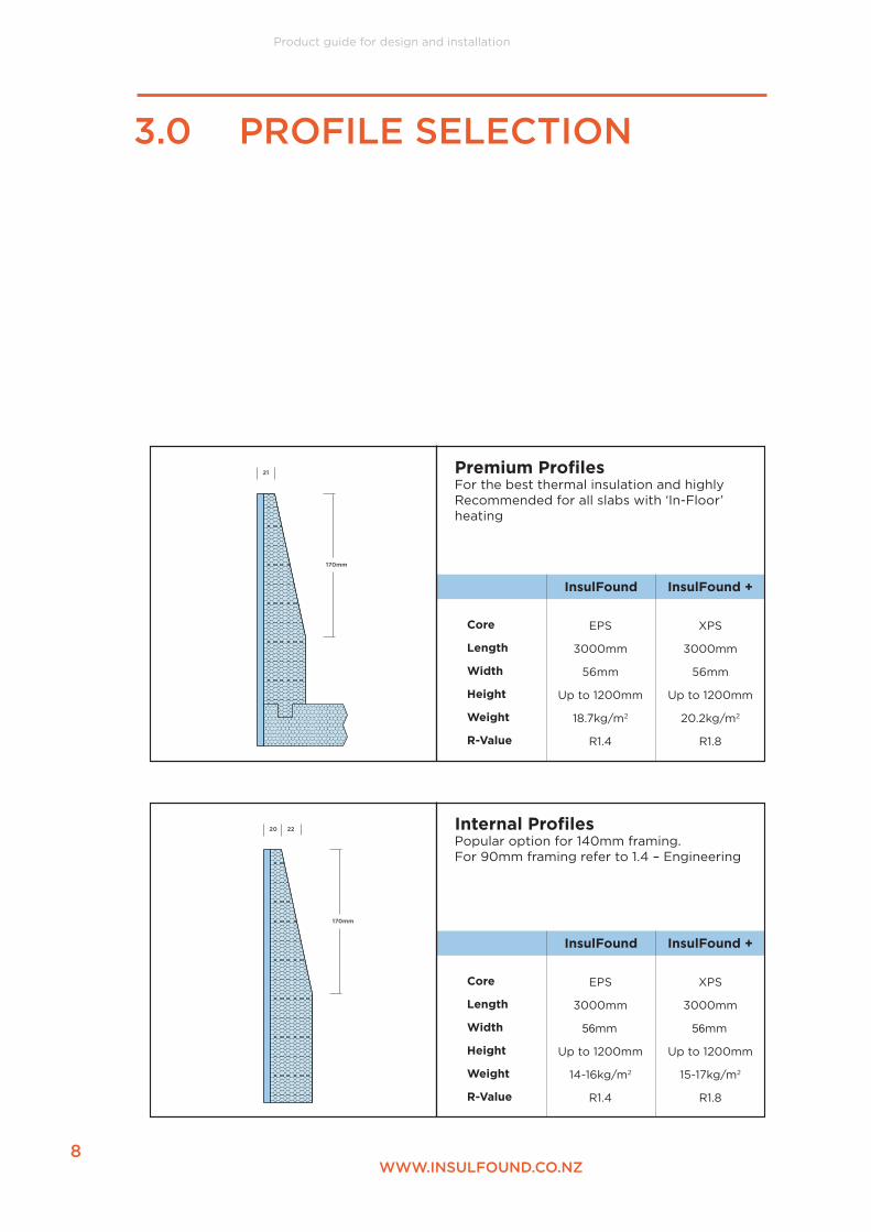
Premium Profiles For the best thermal insulation and highlyRecommended for all slabs with ‘In-Floor’ heating
EPS
3000mm
56mm
Up to 1200mm
18.7kg/m2
R1.4
XPS
3000mm
56mm
Up to 1200mm
20.2kg/m2
R1.8
21
170mm
InsulFound InsulFound +
Core
Length
Width
Height
Weight
R-Value
Internal Profiles Popular option for 140mm framing.For 90mm framing refer to 1.4 – Engineering
EPS
3000mm
56mm
Up to 1200mm
14-16kg/m2
R1.4
XPS
3000mm
56mm
Up to 1200mm
15-17kg/m2
R1.8
20 22
170mm

Product guide for design and installation
9WWW.INSULFOUND.CO.NZ
InsulFound InsulFound +
Core
Length
Width
Height
Weight
R-Value
External Profile For timber framing where hold down bolt position is a limiting factor.
EPS
3000mm
62mm
Up to 1200mm
14-16/m2
R1.4
XPS
3000mm
62mm
Up to 1200mm
15-17/m2
R1.8
55mm
32mm
InsulFound InsulFound +
Core
Length
Width
Height
Weight
R-Value
Brick Profile For cladding systems complying with NZBC E2/AS1 9.2. Masonry Veneer that require a rebated foundation, refer to E2/AS1 figure 73D(i).
EPS
3000mm
31mm
Up to 1200mm
9.3kg/m2
R0.7
XPS
3000mm
31mm
Up to 1200mm
10.1kg/m2
R1.0
15
InsulFound InsulFound +
Core
Length
Width
Height
Weight
R-Value
Retrofit Profiles Used with existing concrete slabs.
EPS
3050mm
56/31mm
Up to 1200mm
9.7/9.3 kg/m2
R1.4/R0.7
XPS
3050mm
56/31mm
Up to 1200mm
11.2/10.1 kg/m2
R1.8/R1.0
18mm36mm

Product guide for design and installation
10WWW.INSULFOUND.CO.NZ
3.1 INSULFOUND PREMIUM
For FULL edge and under footing insulation, where 90% of slab heat loss occurs. Reputable ‘in-floor’ heating contractors recommend this as a minimum for heated floors. Premium is supplied as a ‘clip together’ flat pack, which saves on freight volume and cost.
Premium sits inside the slab edge and includes 50mm tapered slab edge and under footing foam. Both are to the height & width dimensions required (add tie beam base and under-slabsystem as required).
Hold Down Bolt
140x45mm Bottom Plate
Figure 5 External Profile Installation
Product guide for design and installation
11WWW.INSULFOUND.CO.NZ
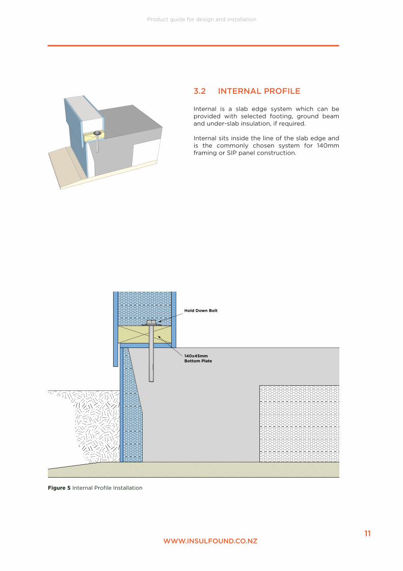
3.2 INTERNAL PROFILE
Internal is a slab edge system which can be provided with selected footing, ground beam and under-slab insulation, if required.
Internal sits inside the line of the slab edge and is the commonly chosen system for 140mm framing or SIP panel construction.
Hold Down Bolt
140x45mm Bottom Plate
Figure 5 Internal Profile Installation

Product guide for design and installation
12WWW.INSULFOUND.CO.NZ
3.3 EXTERNAL PROFILE
External is a slab edge system which can be provided with selected footing, ground beam and under- slab insulation, if required.
External sits outside the line of the slab edge and is a good solution for 90mm framing or where hold down bolt positioning is an issue.It gives an aesthetic result for cavity cladding system, where it brings the finished foundation line out to, or near, the cladding face. Refer to the particular cladding manufacturer for minimum clearances to the underside of the cladding system.
Hold Down Bolt
90x45mm Bottom Plate
Figure 6 External Profile Installation

Product guide for design and installation
13WWW.INSULFOUND.CO.NZ
Hold Down Bolt
90x45mm Bottom Plate
3.4 BRICK REBATE
Brick rebate is a slab edge system which can be provided with selected footing, ground beam and under-slab insulation, if required. For cladding systems complying with NZBC E2/AS1 9.2. Masonry Veneer that require a rebated foundation, refer to E2/AS1 figure 73D(i).
Brick rebate is a single skinned 31mm thick panel that sits inside the slab edge. Because of its flexibility it must be used in conjunction with traditional boxing. It creates the thermal break that all Insulfound products do but not to the same R value. This is because the deadload of the brick cladding is taken directly by the adjoining concrete. NZBC E2/AS1 section 9.2 Masonry Veneer allows a max 20mm cantilever past the edge of the load bearing slab. Consideration needs to be given by the designer to the thermal transfer between the floor/foundation and the veneer. A suggestion is to use a mortar containing a vermiculite aggregate to the base course to reduce thermal conductivity.
Figure 7 Brick Profile Installation

Product guide for design and installation
14WWW.INSULFOUND.CO.NZ
3.5 INSULFOUND RETRO-FIT
Retro-fit is a slab edge system which is designed for insulating existing slab edges.
Retro-fit is glued to a clean dry concrete surface.A PU (polystyrene safe) low expansion adhesive must be used to void any solvents affecting the polystyrene insulation.
Minimize the mechanical fixings to avoidun-necessary making good. Seal the top edge of Retro-fit to the concrete foundation to avoid water ingress at the junction. Supplied ready for painting, although pre-finishing in a custom colour can be ordered.
Hold Down Bolt
90x45mm Bottom Plate
Figure 8 Retrofit Profile Installation

Product guide for design and installation
15WWW.INSULFOUND.CO.NZ

Product guide for design and installation
16WWW.INSULFOUND.CO.NZ
2. Cut straight lengths of Insulfound to fi t between corners.
1. On a prepared level base set out string lines. As with conventional set out, it is important to ensure string lines are level and square.
InsulFound™ is supplied in 2.7m or 3.0m lengths. It is treated on the exterior face and exposed edges with a proprietary water-resistant treatment. Panels should be butt jointed and fi nished with a fl exible sealant before fi nal painting.
If panels are used inside a conventional boxing system they can be secured with a minimum number of screws from the outside. (Remember to remove them when stripping.)
Any cut edges must be re-sealed with a cementitious primer/sealer.
Any screw holes, chips or minor damage must be repaired using exterior grade fi ller and re-sealed, as above.
NB: Face, and edges of panels are water-resistant treated at manufacture. Any moisture diff usion from concrete slab will migrate, over time, through the vapour permeable coating.
InsulFound™ may replace conventional boxing and become the formwork for the foundation and fl oor slab edge. It should be supported and braced the same as conventional formwork, in accordance with best trade practice by competent tradesperson.
Care should be taken while fi xing bracing to minimise the amount of fi nishing required on removal. InsulFound saves time on stripping and will result in a high standard of fi nish for fi nal painting.
Bracing requirments should be determined by a competent technician. QuicFab NZ Ltd accepts no liability for incorrect setout or bracing.
4.1 PROCEDURE
4.0 INSTALLATION

Product guide for design and installation
17WWW.INSULFOUND.CO.NZ
3. All corners should be mitred. QuicFab reccommends the use of generic steel brackets (Multigrips or equiv.) fi tted to the corners.
5. When fi nished joining panel lengths, there will be a continuous length of InsulFound setting out the perimeter of the slab.
6. QuicFab recommend braces to be placed 300mm max. from the corners and at 600mm max. centres. Braces should overlap any joints of InsulFound lengths.
4. Ensure the top edge of the adjacent panels are even. Use a poly safe adhesive to fi x lengths together.
Timber BracesSteel Braces
Adhesive

Product guide for design and installation
18WWW.INSULFOUND.CO.NZ
5.0 SPECIFIC DETAILS
20mm30mm
Lay concrete to the inside of the InsulFound formwork. Create rebate in concrete, cut and remove InsulFound upstand after concrete has set.
Cut down Internal InsulFound profile and box externallly to support slab edge
30mm
50mm
20mm
5.1 EXTERNAL - GARAGE DOOR REBATE
5.2 INTERNAL - GARAGE DOOR REBATE
130mm
30mm
WANZ bar at height to suit, fixed via 8G x 65 SS Screw and Rawl plug @ 150mm from the corners and 450mm thereafter
Remove EPS in a 100mm wide strip behind each bolt fixing position before pouring slab
5.3 INTERNAL - WANZ BAR FACE FIXED

Product guide for design and installation
19WWW.INSULFOUND.CO.NZ
130mm
30mm
WANZ bar at height to suit, fixed via 8G x 65 SS Screw and Rawl plug @ 150mm from the corners and 450mm thereafter
Remove EPS in a 100mm wide strip behind each bolt fixing position before pouring slab
30mm
WANZ bar at height to suit, fixed via 8G x 65 SS Screw and Rawl plug @ 150mm from the corners and 450mm thereafter
Fit rebate formerin place before pouring slab. Remove former once concrete set and cut down upstand to suit rebate
30mm
WANZ bar at height to suit, fixed via 8G x 65 SS Screw and Rawl plug @ 150mm from the corners and 450mm thereafter
Fit rebate formerin place before pouring slab. Remove former once concrete set and cut down upstand to suit rebate
5.4 INTERNAL - WANZ BAR TOP FIXED
5.5 EXTERNAL - WANZ BAR TOP FIXED
5.5 EXTERNAL - WANZ BAR TOP FIXED

Product guide for design and installation
20WWW.INSULFOUND.CO.NZ
6.1 REQUIREMENTS
All InsulFound™ product is pre-sealed with a specially modified proprietary coating treatment specifically developed for Insulfound™. It is recommended that a minimum acrylic finish coat be applied after installation.
On request, InsulFound™ can be pre-finished with a chosen colour and/or texture.
6.2 PREPARATION
1. Vertical joints between panels (that have been sealed if cut before fixing) should be filled with a flexible external PU sealant. (Due to the varying properties of adjacent materials, QuicFab board, concrete, surrounding ground and foam insulation, it is likely that there will be minor movement over time. It is therefore advised not to try and plaster flush vertical joints)
2. Fill screw holes, chips and minor damage in panels with a suitable external filler and sand smooth.
3. Touch up repairs with a cementitious water-proof sealer.
6.3 WATERPROOFING
The panel, as described in 4.0 above, has been water-resistant treated.
Only if the surrounding soil is non-draining, or likely to be moist for prolonged periods, need tanking be applied below ground.
6.4 PAINT
As a minimum, finish with a chosen acrylic top coat.
Apply desired paint system in accordance with the paint manufacturer’s specification.
Resene paints are not recommended. If chosen for use, Resene signoff is required.
A textured paint system gives a plaster appearance.
NB. Expensive plaster systems, as used by other insulating suppliers, are not recommended.
6.0 FINISHING

Product guide for design and installation
21WWW.INSULFOUND.CO.NZ
This Technical Manual covers the non-structural slab insulation and not the concrete, reinforcing or engineering.
Design and calculations can be provided by our Registered Engineer. This may include site inspection and signoff. (PS1 – design, PS2 – design review, PS4 – construction review)
The following are our recommendations for hold-down bolting where concrete cover and edge distances do not comply with NZSS 3604: 7.5.12.
It should be noted that concrete covers can be quite low (20 – 25mm) where InsulFound™ contributes to keeping moisture and oxygen away from the reinforcing.
It is a much more positive detail if the drilled hold down bolts are inside the edge of the slab trimmer bar.
7.1 HOLD DOWN BOLTS
7.1.1 - TIMBER FRAMINGMinimum bolt cover must be maintained at 50mm
Bolts may be off centre by 30mm maximum. This becomes critical when using 90mm framing with InsulFound™ Premium and Internal profiles. In these situations, it is recommended to use:
1. Cranked cast-in bolts, or
2. For drilled bolts, start bolts central in plate, but run down at a 15degree angle away from slab edge, or
3. Specific Engineer Design fixing.
For other Insulfound™ profiles with 90mm framing and 140mm framing generally, this critical requirement is not as important because the bolt offset and the concrete cover are more easily achieved.
7.1.2 - STRUCTURAL INSULATED PANEL CONSTRUCTIONThe above recommendations apply equally to SIP construction.Except, where bracing panels are required the hold down bolts MUST be central on the plate.
7.2 R-VALUE CALCULATIONS
7.2.1 Cupolex floor slab systemIndependent analysis has been done by Enercon using InsulFound™ as edge insulation.
The results show if InsulFound™ slab edge insulation, insulation depth and insulating covers for domes are installed, the R-values range between 3.84 and 4.33 m2-K/W.
Refer Appendix 1 – Cupolex
7.0 ENGINEERING

Christchurch: 210 Hazeldean Rd, Addington – Wellington: Level 10 Grand Annexe, 84 Boulcott St, CBD – Takaka: 72 Matenga Rd, Ligar Bay
Phone: 03 384 7905 – Email: [email protected] – Web: www.enercon.co.nz
Cupolex
R Value Calculations
Prepared for: Mike Teddy
Cupolex Solutions
11 September 2019

Page 2 of 6
Introduction
Cupolas Solutions engaged Enercon to conduct an R-Value calculation for three typical Cupolex
floor-slab insulation designs, for purposes of an independent analysis of insulation value. This
report summarises the calculations.
Three designs are referred to:
• 14 Memorial Drive (Memorial)
• 285 Church Road (Church)
• 209 Willowbank Avenue (Willowbank)
1. Calculation Results
The R-Value (calculated as per example as presently drawn) ranges between 2.13 and 2.50
m2-K/W. If slab edge insulation, insulation depth and insulating covers for domes are installed,
the R-values range between 3.84 and 4.33 m2-K/W.
The components that make up the R-value of the overall construction (i.e. combined the R-value
of each element x the proportion of floor area that each element covers) are shown in Table 1.
Note that contribution to R-value is listed as per analysis section of this report. Sections are:
2.1 Area to perimeter (A/P) ratio
2.2 Cupolex domes and ribs (and adjacent areas)
2.3 Other contributors to base R value
2.4 Slab edge insulation (optional)
2.6 Insulating covers for domes (optional)
2.5 Slab edge insulation multiplier factor (additional R-value to initiatives from all previous
sections combined)
Table 1 – Calculation of overall R Value per example
Site 2.1 2.2 2.3 2.4 2.5 2.6 Maximum Unit
Memorial 1.71 0.175 0.24 0.52 0.84 0.35 3.84 m2-K/W
Church 2.05 0.175 0.34 0.52 0.85 0.39 4.33 m2-K/W
Willowbank 1.98 0.175 0.34 0.52 0.83 0.22 4.07 m2-K/W
Page 3 of 6
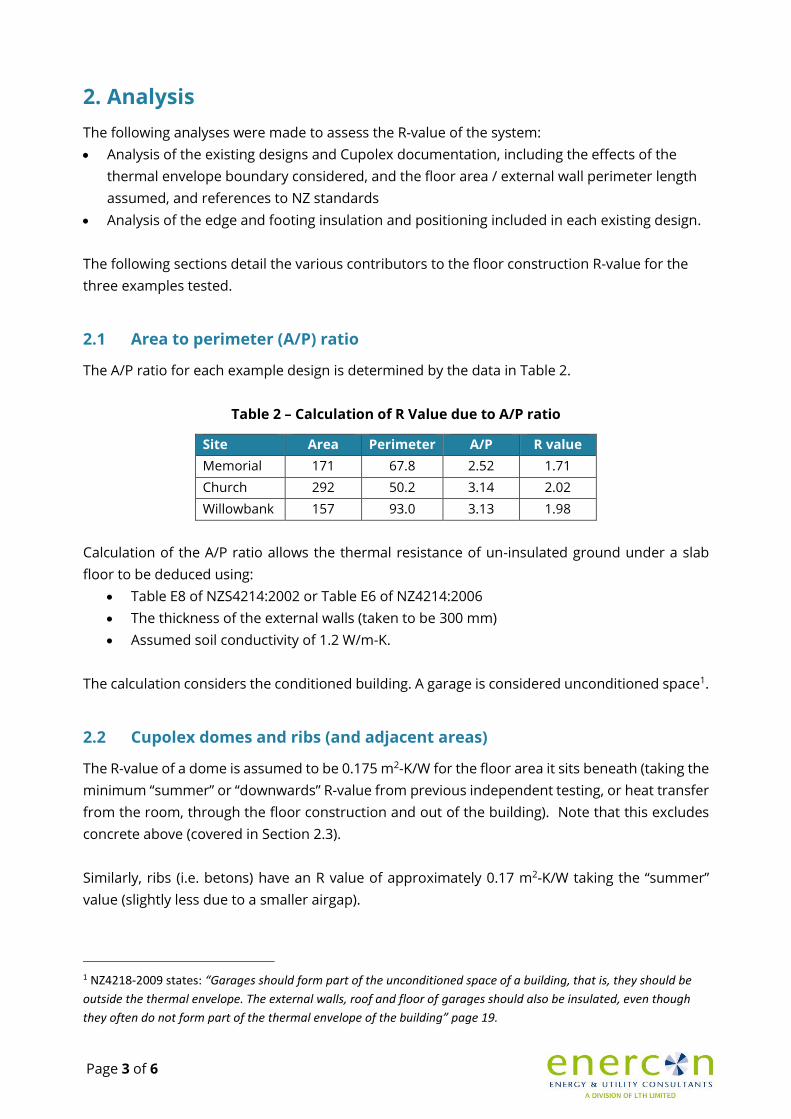
2. Analysis
The following analyses were made to assess the R-value of the system:
• Analysis of the existing designs and Cupolex documentation, including the effects of the
thermal envelope boundary considered, and the floor area / external wall perimeter length
assumed, and references to NZ standards
• Analysis of the edge and footing insulation and positioning included in each existing design.
The following sections detail the various contributors to the floor construction R-value for the
three examples tested.
2.1 Area to perimeter (A/P) ratio
The A/P ratio for each example design is determined by the data in Table 2.
Table 2 – Calculation of R Value due to A/P ratio
Site Area Perimeter A/P R value
Memorial 171 67.8 2.52 1.71
Church 292 50.2 3.14 2.02
Willowbank 157 93.0 3.13 1.98
Calculation of the A/P ratio allows the thermal resistance of un-insulated ground under a slab
floor to be deduced using:
• Table E8 of NZS4214:2002 or Table E6 of NZ4214:2006
• The thickness of the external walls (taken to be 300 mm)
• Assumed soil conductivity of 1.2 W/m-K.
The calculation considers the conditioned building. A garage is considered unconditioned space1.
2.2 Cupolex domes and ribs (and adjacent areas)
The R-value of a dome is assumed to be 0.175 m2-K/W for the floor area it sits beneath (taking the
minimum “summer” or “downwards” R-value from previous independent testing, or heat transfer
from the room, through the floor construction and out of the building). Note that this excludes
concrete above (covered in Section 2.3).
Similarly, ribs (i.e. betons) have an R value of approximately 0.17 m2-K/W taking the “summer”
value (slightly less due to a smaller airgap).
1 NZ4218-2009 states: “Garages should form part of the unconditioned space of a building, that is, they should be
outside the thermal envelope. The external walls, roof and floor of garages should also be insulated, even though
they often do not form part of the thermal envelope of the building” page 19.
Page 4 of 6
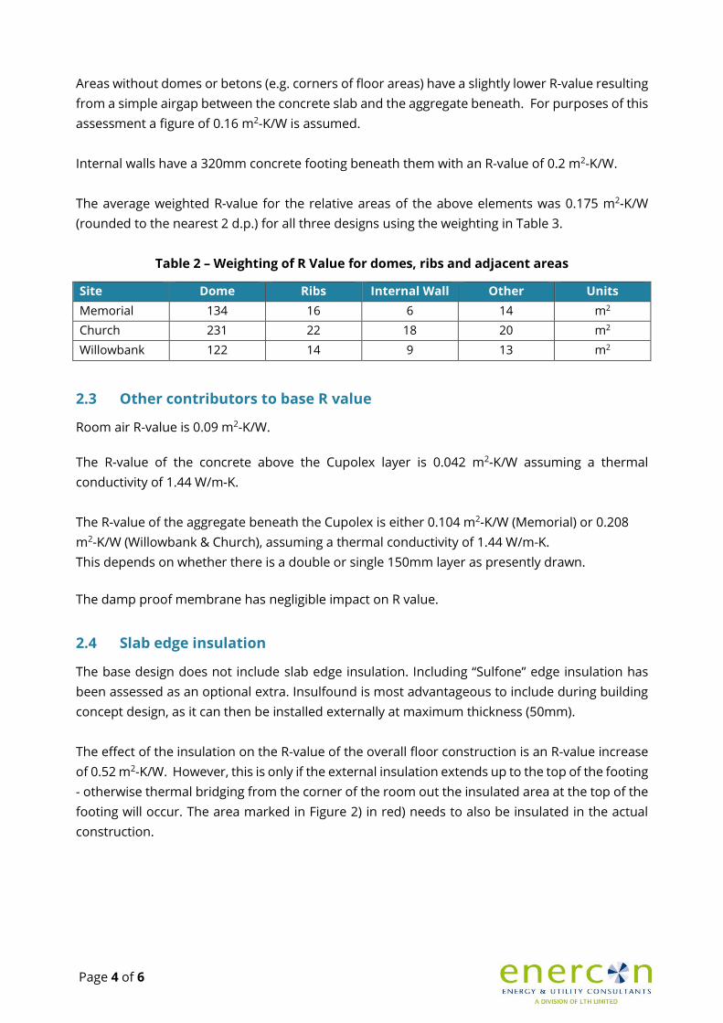
Areas without domes or betons (e.g. corners of floor areas) have a slightly lower R-value resulting
from a simple airgap between the concrete slab and the aggregate beneath. For purposes of this
assessment a figure of 0.16 m2-K/W is assumed.
Internal walls have a 320mm concrete footing beneath them with an R-value of 0.2 m2-K/W.
The average weighted R-value for the relative areas of the above elements was 0.175 m2-K/W
(rounded to the nearest 2 d.p.) for all three designs using the weighting in Table 3.
Table 2 – Weighting of R Value for domes, ribs and adjacent areas
Site Dome Ribs Internal Wall Other Units
Memorial 134 16 6 14 m2
Church 231 22 18 20 m2
Willowbank 122 14 9 13 m2
2.3 Other contributors to base R value
Room air R-value is 0.09 m2-K/W.
The R-value of the concrete above the Cupolex layer is 0.042 m2-K/W assuming a thermal
conductivity of 1.44 W/m-K.
The R-value of the aggregate beneath the Cupolex is either 0.104 m2-K/W (Memorial) or 0.208
m2-K/W (Willowbank & Church), assuming a thermal conductivity of 1.44 W/m-K.
This depends on whether there is a double or single 150mm layer as presently drawn.
The damp proof membrane has negligible impact on R value.
2.4 Slab edge insulation
The base design does not include slab edge insulation. Including “Sulfone” edge insulation has
been assessed as an optional extra. Insulfound is most advantageous to include during building
concept design, as it can then be installed externally at maximum thickness (50mm).
The effect of the insulation on the R-value of the overall floor construction is an R-value increase
of 0.52 m2-K/W. However, this is only if the external insulation extends up to the top of the footing
- otherwise thermal bridging from the corner of the room out the insulated area at the top of the
footing will occur. The area marked in Figure 2) in red) needs to also be insulated in the actual
construction.

Page 5 of 6
2.5 Insulating covers for domes
Domes are able to be fitted with an optional insulating cover. This provides a minimum “summer”
R-value of 1.3 m2-K/W for the dome itself. The domes are only a proportion of the overall floor
area in each example. This results in an R-value increase from insulating covers of around 0.83
and 0.85 m2-K/W across the overall floor area for each example (assuming the same weighting of
dome area described in Table 2).
2.6 Slab edge insulation multiplier factor
NZS 4214, Table E9 lists a “multiplier factor” for edge insulated slab-on-ground floors.
This refers to the expected multiplication to the R-value provided by edge insulation if the edge
insulation extends some depth beneath the ground while remaining alongside the floor
construction.
In other words, the slab is level with the ground and the top of the insulation, and the insulation
extends the length of the slab thickness.
The design depth for the base R-value is assumed to be 0mm (all of the insulation is exposed), as
this is how the details are presently drawn. However, if the insulation is deeper than ground level
the multipliers can apply as significantly as is documented in Table 3.
Note that maximum R-value in Table is the maximum achievable R-value incorporating all of the
items in Sections 2.1 – 2.5 of this report.
Table 3 – Calculation of slab edge multiplier and impact on R-value
Site Insulation
thickness
Max. edge
insulation
depth
Average
half-width
of slab
floor
Units Multiplier Max. R-
value
Max. R-
value
increase
Memorial 50 320 3,500 mm 1.10 3.47 0.35
Church 50 320 3,500 mm 1.10 3.88 0.39
Willowbank 50 320 5,950 mm 1.06 3.82 0.22
Page 6 of 6
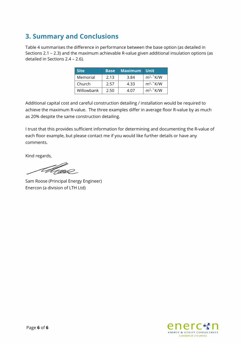
3. Summary and Conclusions
Table 4 summarises the difference in performance between the base option (as detailed in
Sections 2.1 – 2.3) and the maximum achievable R-value given additional insulation options (as
detailed in Sections 2.4 – 2.6).
Site Base Maximum Unit
Memorial 2.13 3.84 m2-˚K/W
Church 2.57 4.33 m2-˚K/W
Willowbank 2.50 4.07 m2-˚K/W
Additional capital cost and careful construction detailing / installation would be required to
achieve the maximum R-value. The three examples differ in average floor R-value by as much
as 20% despite the same construction detailing.
I trust that this provides sufficient information for determining and documenting the R-value of
each floor example, but please contact me if you would like further details or have any
comments.
Kind regards,
Sam Roose (Principal Energy Engineer)
Enercon (a division of LTH Ltd)