PRODUCT GUIDE 2017 - cms.esi.info · PDF file• To raise the profile of concrete product...
19
www.andertonconcrete.co.uk PRODUCT GUIDE 2017
Transcript of PRODUCT GUIDE 2017 - cms.esi.info · PDF file• To raise the profile of concrete product...

www.andertonconcrete.co.uk
EDITION 2
PRODUCT GUIDE 2017

Anderton Concrete Products Ltd Mission Statement
• Demanding that everything we do leads to a cleaner, healthier, safer environment.
• To liaise with the Health & Safety Executive and other bodies, including suppliers.
• To promote good safe working practices within our industry.
• Exceeding customer expectations by always being first to market with the best products.
• Partnering with our customers to make sure they succeed.
• To raise the profile of concrete product manufacturing as a skilled industry.
• Committed to ensuring customer satisfaction by continually improving performance in the development of products, quality, technique and service.
• To satisfy this commitment all employees must understand the importance and responsibilities of quality in their work, and utilise only those approved working practices which will assure the required quality standards are achieved.• Keystone (EN 771-3:2011)
• Slopeloc (EN 771-3:2011)
• Stepoc (EN 15435:2008)
www.anderton-ce.co.uk
Certified by BSI – FM 559191
MISSION STATEMENT
2 www.andertonconcrete.co.uk Telephone 01606 535300 3
HEALTH & SAFETY POLICY
ANDERTON CONCRETE PRODUCTS LTD seeks to achieve industry best practice standards of health and safety. We recognise that this is a critical issue for all of our stakeholders, particularly for our employees and contractors.
Our health and safety policy, applied throughout the company, is to:
• Comply, at a minimum, with all applicable legislation and continually improve our health and safety stewardship towards industry best practice
• Ensure that our employees and contractors respect the Company’s health and safety imperatives
• Ensure that our company provides a healthy and safe workplace for our employees and contractors, and take due care of all customers and visitors at our locations
• Require all our company employees and contractors to work in a safe manner as mandated by law and industry best practice
Health and Safety ManagementHealth and Safety Management is a daily priority of line management. Safety results for the company are closely monitored by senior management and are reported to the Anderton Concrete Products Ltd Board on a monthly basis.
Line management is responsible for ensuring that company health and safety policies are fully adhered to, and that site managers and employees, supported by company safety officers, are trained in health and safety risk analysis and prevention.
Where accidents occur they are thoroughly investigated and corrective action is taken to avoid a recurrence. Lessons learned are actively shared via Safety Best Practice groups.
Safety PerformanceWe have found that the most common causes of accidents are slips, trips and falls, injury by falling and moving objects and improper manual handling: with additional care and attention by all, many of these accidents are preventable. Our goal is zero accidents. Due to the nature and size of our business, these are extremely challenging goals. We will continue to devote substantial management and employee time and all the appropriate resources to this area to progress company performance towards those targets.
Product SafetyThe products delivered by Anderton Concrete Products Ltd, when properly used, present negligible health risks. Material Safety Data Sheets advising on optimal application procedures are available on request.

STEPOC PAGES 6 - 13 Manufactured to harmonised standard EN 15435:2008
THE REAL ALTERNATIVE TO SHUTTERED CONCRETE A system of concrete shuttering blocks that are highly-engineered and dimensionally co-ordinated. Stepoc is designed to readily accept vertical and horizontal reinforcement for use where structural performance is the prime consideration and offering cost savings on both time and labour.
KEYSTONE PAGES 20 - 29 Manufactured to harmonised standard EN 771-3:2011
REPLACES GABION, CRIB AND CAST-IN-SITU WALLS The number one retaining wall system on the market today; available in a range of finishes and colours providing practical solutions for low-level gravity walls through to tall structural walls in both the domestic and commercial markets.
SLOPELOC PAGES 14 - 19 Manufactured to harmonised standard EN 771-3:2011
A STYLISH MODULAR HARD FACING TO SOIL SLOPES Slopeloc provides either a simple solution for low level gravity walls in the domestic DIY sector or an engineered solution for taller walls where an alternative to vertical walls is preferred.
CONCRETE BLOCK ANCILLARIES PAGE 30 - 31
DELIVERY VEHICLE DETAILS PAGE 32 - 33
HEALTH & SAFETY POLICY PAGE 34
CONTACT PAGE 35
There are more occasions in the construction
market today where there is limited
ground for development, and a retaining
wall may be specified to extend
the area of level ground available for building.
Alternatively, walls may be simply required
to create terraces and attractive
landscaping, particularly on
the more prestigious developments.
Anderton Concrete offers a whole
range of retaining wall and soil
reinforcement solutions to cater
for these requirements.
INTRODUCTION
4 www.andertonconcrete.co.uk Telephone 01606 535300 5
• All product dimensions are in mm unless otherwise stated.• All stated weights are correct at time of going to press. E&OE

STEPOCTHE REAL ALTERNATIVE TO SHUTTERED CONCRETE.
Stepoc’s unique design enables reinforcement to be positioned in order to maximise the engineer’s design.
Stepoc is filled with concrete, which is pumped down through the inter-connected cavities in the blocks. The blocks unique design creates a cascade or waterfall effect which ensures a smooth filling of the pumped concrete, forcing out air and eliminating segregation, to create walls which have immense compressive and lateral strength. Stepoc walls have achieved the highest rating for a Security Barrier System under the SEAP (Security Equipment Assessment Panel) testing regime.
Stepoc enables the fast construction of single skin retaining walls up to 4.0 metres high, subject to a design carried out by a structural engineer. Stepoc can be filled in a single pour from 1.8 - 2.25m depending on block thickness. Stepoc is available in three widths, 200, 256 & 325mm and at less than 20kg per unit.
Stepoc is proven in use on applications the length and breadth of the UK with a huge growth in sales over recent years proving its suitability and popularity. Anderton has a team of experienced personnel with a wealth of knowledge in the construction industry on hand to assist the customer. Stepoc combines the ease of blockwork construction with the versatility of in-situ concrete, and yet is faster to apply than both, making it an ideal component for :
• Retaining walls
• Basement walls
• Flood Alleviation Schemes
• Swimming pools
• Laterally-loaded panels
• Blast panels • Lift shafts • Platform edges
• Multi Storey Structures
Brick Clad Stepoc
Stepoc Retaining Walls
Wine Cellar using 256mm Stepoc
STEPOC
6 www.andertonconcrete.co.uk Telephone 01606 535300 7

TYPE 256 TYPE 325
V2 - Full Length Standard V3 - Full Length Plain EndV5 - Third Length Standard V6 - Third Length Plain End
Z2 - Full Length Standard Z3 - Full Length Plain EndZ4 - Half Length Standard
V2
V3
V5
V6
Z2
Z3
Z4
• Fire Resistant To Euroclass A1.
TYPE 200
L2 - Full Length Standard L3 - Full Length Plain EndL4 - Half Length Plain End
Note: All products are supplied on pallets and shrink wrapped to aid in transportion and handling.
L2
L3
L4
STEPOC BLOCK DIMENSIONS
UNIT Length (mm) Width Height Weight (kg) Pack Size m2 per pk Product Code
TYPE 200
L2 400 200 225 18.5 40 3.60 STEP200L2FLI
L3 400 200 225 18.5 40 3.60 STEP200L3FLE
L4 200 200 225 9 80 3.60 STEP200L4HLI
TYPE 256
V2 400 256 225 19.8 32 2.88 STEP256V2FLI
V3 400 256 225 20 32 2.88 STEP256V3FLE
V5 133 256 225 8 96 2.88 STEP256V5TLI
V6 133 256 225 8.5 96 2.88 STEP256V6TLE
TYPE 325
Z2 325 325 225 19.8 24 1.75 STEP325Z2FLI
Z3 325 325 225 20 24 1.75 STEP325Z3FLE
Z4 162.5 325 225 10.5 48 1.75 STEP325Z4HLI
STEPOC
8 www.andertonconcrete.co.uk Telephone 01606 535300 9

Stepoc for swimming pool applications
Pour HeightsThere is a maximum height for each pour so that stability is not lost in the dry laid blocks as they are filled. Lower heights for each pour can also be used. We would also recommend the use of temporary propping at free ends and corners during the filling process. The maximum heights are:
STEPOC Build Heights
Stepoc Max Courses Build Height
200 Stepoc 8 1.80m
256 Stepoc 10 2.25m
325 Stepoc 10 2.25m
If multiple concrete pours are required, the concrete of the previous pour should finish 50-75mm from the top of the course of Stepoc, with the vertical bars projecting the equivalent of a splice length taken from the engineer’s schedule. This is to ensure a proper key between consecutive pours.
Pouring concrete
Stepoc for Landscaping
Concrete MixThe concrete should possess the characteristic strength specified by the structural engineer who has carried out the design of the wall, but not less than C28/35 as per BS EN 206:2013+A1:2016
STEPOC Concrete Mix
Stepoc Concrete Infill
200 Stepoc 0.12m3 per m2
256 Stepoc 0.15m3 per m2
325 Stepoc 0.19m3 per m2
The concrete should be designed to be suitable for the specific means of delivery, and a consistence class of S4. The maximum aggregate size should not exceed 10mm and the mix should contain no less than 300kg of cement per cubic metre of fresh concrete.
Filling is best accomplished by a concrete pump or skip with a 75mm nozzle, and the design of the concrete should take this into account. Mechanical vibration must not be used. The use of water reducing agents is acceptable to lower cement content in the mix design.
Stepoc creating curved walls
DesignThe design of Stepoc walls should be carried out by a qualified structural engineer using the appropriate method for the particular situation. Stepoc walls can either be designed as a reinforced masonry wall to EN 1996-1-1: 2005 +A1:2012 or a reinforced concrete section to BS EN 1992-1-1 (2004 +A1:2014)
BasementsWhere stepoc is being used in a basement situation waterproofing should be designed by a qualified engineer.
STEPOC
10 www.andertonconcrete.co.uk Telephone 01606 535300 11

FinishingStepoc can be faced with a number of different finishes including brick, stone and render. Wall ties can be incorporated during construction of the walls to allow the facing material to be tied in as appropriate.
DID YOU KNOW?Anderton Concrete provide typical design examples and additional guidance to assist the engineer with the design process.
All products can also be downloaded as CAD files. Anderton Concrete also provide standard setting out drawings for corners, ends and rebar positions. Stepoc facilitates added service penetrations
Stepoc wall finished with render
Stepoc retaining walls for newbuild
STEPOC Vertical Bar Centres*
Stepoc Centres
200 Stepoc 200mm
256 Stepoc 133mm
325 Stepoc 162.5mm
STEPOC ƒk strength
Stepoc ƒk value
200 Stepoc 14N/mm2
256 Stepoc 18N/mm2
325 Stepoc 18N/mm2
Stepoc for swimming pool applications* chart for standard wall run, for setting out of corners and ends please see details supplied with quote
STEPOC
12 www.andertonconcrete.co.uk Telephone 01606 535300 13
ULS Bending Moment for Stepoc 200, 256, 325
200mm STEPOC 256mm STEPOC
325mm STEPOC

A Straightforward Dry Lay Block System For Facing Retaining Slopes.
Slopeloc can be used domestically in garden retaining wall projects or on a larger scale in commercial applications for embankment repairs and situations where an aesthetic slope is required.
Available in three standard colours: • Flint • Yorkstone • Sandstone
Slopeloc is a dry laid concrete block system with a unique ribbed face appearance that can be built as a gravity wall, and therefore be easily erected by the DIY enthusiast or alternatively as a structural wall by more experienced installers. When the blocks are used in conjunction with a geogrid (i.e. Tensar RE500 series) and the patented blue comb connector, exceptionally strong reinforced earth walls can be constructed up to a height of approximately 5m which are suitable for both domestic and commercial applications. Slopeloc can also be used as a facing material to stabilised slopes therefore providing a more attractive finish that may suit the project requirements.
KEY BENEFITS:
• Unique economical alternative to vertical retaining walls
• Professional indemnity backed design
• All units less than 20kgs
• Proven block/grid connection
• Choice of colours - bespoke colours available to special order
• Fast, efficient delivery
SLOPELOCINNOVATIVE & ATTRACTIVE RETAINING SYSTEM FOR SOIL FACED SLOPES.
Feature Slopeloc wall
SLOPELOC
14 www.andertonconcrete.co.uk Telephone 01606 535300 15
Reinforced earth Slopeloc
Slopeloc landscaping options

Typical Cross Section: Notes:
1. Wall shall be founded upon Competent Foundation Soils.
2. Slopeloc walls have been designed on a 5kPa Surcharge
3. Well graded stone fill assumed with the following geo-technical properties PHi’ pk=36°
SLOPELOC
Dimensions (mm) Exposed Face area Weight kg
300L x 245W x 125H 0.0375m2 16.5
Pack Size: 72 - Coverage 2.70m2
The reproduction of colour is as close as is possible within the photographic and printed processes. Where precise colour tolerances are vital, you are advised to view actual product samples.Whenever practical, blocks should be mixed from more than one pack.
Wall with upper slope no steeper than 1:3
Wall with no upper slope
Cross section of a 2.3m wall project
YorkstoneFlint Sandstone
Standard Colours
Slopeloc boundary to a perimeter fence
DESIGN SERVICEWe have many years of experience developing our Slopeloc products and are able to offer exceptional levels of design and service support. We have an experienced technical support team and a very comprehensive design support programme to assist you with your individual requirements.
SLOPELOC
16 www.andertonconcrete.co.uk Telephone 01606 535300 17

WHERE APPLICABLE CONSTRUCTION OF THE WALL SHALL BE IN ACCORDANCE WITH THE UK HIGHWAYS AGENCY SPECIFICATION FOR HIGHWAY WORKS SERIES 600.
The following is an outline construction sequence to assist the contractor in the construction of a Slopeloc Wall System.
1 - PREPARATION
Excavate for the formation and levelling strip to the details shown on the elevations and typical cross sections. Care should be taken with any temporary works cut slopes to ensure they are cut to a safe inclination. Construction into existing ground should be benched to provide a positive key. Cut slope to be cut no steeper than 1:1.
Formation shall be tested to verify an acceptable bearing stratum exists for the support of the retaining wall. Minimum allowable bearing capacity requirement of 230kPa. All unsuitable soils shall be excavated and replaced with compacted granular fill.
Install ST2 mass concrete levelling strip 600mm wide x 150 deep minimum 450mm below finished ground level for reinforced earth walls.
2 - INSTALLING THE BASE COURSE OF BLOCKS
The first course is critical for accurate and acceptable construction.
The wall will build at a natural slope of 68º. Setting out for the base course should allow for the wall inclination.
Bed the first course of Slopeloc units side by side on the levelling strip allowing for a 2mm gap between the block. The blocks should be bedded on a mortar bed of cement: sand (1:3 ratio) ensuring that the top of the block is uppermost (recess on top of block).
Ensure that the units are level front to back, side to side and to the correct alignment. Align the blocks with a string line placed on the back of the block, or for radius walls to the appropriate radius, but using the back of the block as the datum.
Allow the mortar bed to cure before laying additional courses.
3 - INSTALLATION OF DRAINAGE MATERIAL AND BACKFILL TO REINFORCED EARTH WALLS
When required a min 300mm basal drainage layer comprising the 4/20mm crushed coarse aggregate shall be installed as detailed on the drawings. The drainage layer shall extend up cut slopes to intersect any water seepage.
Structural granular fill is placed and compacted in 125mm layers to correspond with the height of the blocks. The fill shall be placed by mechanical plant with an opening bucket, such that it causes the fill to cover the geogrid in a uniform manner. Fill material to be HA Class 6I in accordance with HA Specification for Highway Works.
When placing and compacting fill care should be taken to avoid contact with the facing units by any of the compaction plant and the following restrictions should apply:
All construction plant, including compaction equipment with a mass exceeding 1000kg should be kept at least 2m from the face of the wall. Compaction plant within 2m of the wall should be restricted to vibrating rollers having a mass per metre width not exceeding 1300kg or plate compactors with a mass less than 1000kg
Compaction should always occur parallel to the face and commence nearest the facing units, working away towards the free end of the grid. Compaction shall be in accordance with the Highways Agency Specification for Highway Works Series 600 Table 6/4. The contractor should use this table to select his plant, compaction layer thickness, and number of passes of compaction plant.
If there is any doubt regarding the degree of compaction obtained then site trials should be undertaken.
5 - INSTALLATION OF TENSAR GEOGRID AND ADDITIONAL BLOCK COURSES TO REINFORCED EARTH WALLS
Ensure that the compacted fill is generally level to receive the geogrid. Sweep the blocks clean to remove all debris.
Layers of Tensar geogrid are to be incorporated at the specific levels as detailed on the elevation and cross section. This is generally on top of the base course of blocks and then at 375mm vertical centres. The length of the geogrid required for stability is shown on the elevations and cross sections.
The required length of Tensar geogrid is cut from the roll. Trim the ribs so that they project 50mm in front of the transverse bar that runs across the 1.3m width of geogrid.
Place the prepared end of the grid over the recess in the top of the Slopeloc block and locate the blue moulded connectors around the transverse bar such that the blue moulded connector is trapped between the transverse bar of the geogrid and the back face of the recess in the block. Ensure that each aperture of the geogrid is covered by a connector. The connectors may be split where necessary.
Position the geogrid and connector assembly neatly into the recess and push down firmly. The next course of
blocks is placed on top taking care not to disturb the geogrid and connector in the block below. Repeat this procedure for the whole course ensuring that adjacent lengths of geogrid are abutted at the wall face. When positioning the geogrid around curved wall sections it may be necessary to cut the geogrid along its length to create narrow strips to maintain the full connection between the geogrid and the recess in the top of the Slopeloc block.
The placing of the blocks may act to loosen the connection of the geogrid and blue connector. The geogrid should therefore be lightly tensioned so that the blue connectors are trapped tight between the transverse bar of the geogrid and the back face of the recess in the block. To maintain the tension in the geogrid temporary pegs should hammered into the underlying fill at the rear of the geogrid.
Repeat steps 3, 4 and 5 to construct the wall to the required height. Check for line and level front to back and side to side every 2 to 3 courses of blocks and adjust as necessary by use of shims or thin bed mortar. Alignment should be checked using the rear of the blocks as the datum.
The 300mm drainage stone to the rear of the blocks should be stopped 500mm from the top of the wall. Step the Slopeloc blocks along the top of the wall to the required gradient of the ramp. The top Slopeloc block should be bonded to the underlying block using four spots of construction adhesive provided by the
block supplier. A min 300mm deep layer of impermeable general fill shall be used to cover the structural fill and the surface drainage above the wall should be designed such that water is directed away from the wall face.
6 - INSTALLATION OF ADDITIONAL BLOCK COURSES
Sweep the blocks clean to remove all debris.
The next course of blocks is placed on top of the previous course in a stretcher bond pattern.
The block being placed should be centred over underlying blocks and pulled towards the front of the structure. Make minor adjustments to the alignments as necessary.
7 - TOP OF WALL DETAIL
The final course will generally be completed using a capping unit which should be glued to the top course with the supplied construction adhesive.
SLOPELOC
18 www.andertonconcrete.co.uk Telephone 01606 535300 19

Keystone’s ability to connect positively with proprietary geogrid systems has enabled it to be built to heights of over 15 metres worldwide – making it ideal for roadside and bridge locations and its simple, dry build construction enables it to handle the most challenging site design.
KEYSTONE’S VERSATILITY IS IDEAL FOR:
• Retaining Walls
• Embankments
• Culverts
• Bridge Abutments
• Tunnel Entrances
• Access Ramps
• River Diversions / Flood Alleviation Schemes
AESTHETIC IMPACTKeystone provides design flexibility to meet the unique challenges of modern commercial development projects; whether you are building tall retaining walls, short walls, using curves or corners, considering rapid changes in elevation detail or using Keystone with other specialist materials. This proven system enhances the architectural importance of any structure whether new-build or refurbishment.
A Keystone retaining wall offers a positive solution to the most challenging and demanding design and construction requirements.
This inner strength is complemented by the aesthetic impact of a system capable of combining classic lines, graceful curves, shadows and textures.
Keystone during construction
Keystone walls at Southend-on-Sea
Keystone landscaping project - retaining wall in “flint” finish
KEYSTONETHE NUMBERONE RETAINING WALL SYSTEM ON THE MARKET TODAY.
KEYSTONE
20 www.andertonconcrete.co.uk Telephone 01606 535300 21

DESIGN NOTES:
1. The Contractor shall be solely responsible for the design and construction of all the temporary works propping and shoring.
2. All work is to comply with all relevant health and safety legislation and regulations.
3. Retaining Walls to be founded on cement stabilised ground.
4. Formation soils to be tested to confirm adequate strength, to support retaining walls. Minimum Allowable Bearing Capacity 350kPa. Weaker soils to be excavated and replaced with compacted granular fill.
5. Foundation Soils are liable to deterioration following excavation and should be protected from water at all times. Formation to be blinded/covered as soon as practical.
6. Movement joints between differing types of wall construction to comprise 25mm closed cell polyethlyne with outer 20mm recessed and filled with polysulphide sealant.
7. Fill material to reinforced earth wall shall comply with DoT Class 611 as per Specification for Highway Works (SHW)
Keystone is a system of modular retaining wall units that are manufactured from high strength, durable concrete which are laid dry and can be used in conjunction with a geogrid to provide tall walls or to accommodate high surcharges.
Alternatively, it can be used with or without a concrete backing to create a gravity wall.
Keystone uses a unique high strength fixing system which securely locks the component parts in place. At the centre of the system is the patented blue comb connector that provides exceptionally high connection strengths. A combination of Keystone modular units, positive pin connections and soil reinforcing geogrids delivers ‘rock solid’ stability and performance its enhanced connection between grid and block is critical to ensure economic designs.
Keystone block showing grid connection Simple installation of temporary safety railings
Keystone Compac with grid system retaining wall
Keystone Compac vertical wall with concrete backing & 100mm Capping
Split Face
Smooth Face
KEYSTONE
22 www.andertonconcrete.co.uk Telephone 01606 535300 23

CONSTRUCTION OF THE WALL SHALL BE IN ACCORDANCE WITH THE UK HIGHWAYS AGENCY SPECIFICATION FOR HIGHWAY WORKS SERIES 800.
The following is an outline construction sequence to assist the contractor in the construction of a Keystone Wall System.
1 - PREPARATION
Excavate for the formation and levelling strip to the details shown on the elevations and typical cross sections. Care should be taken with any temporary works cut slopes to ensure they are cut to a safe inclination. Construction into existing ground should be benched to provide a positive key. Cut slope to be cut no steeper then 1:1.
The retaining wall shall be founded upon the cement stabilised foundation soils. The levelling strip shall be cut into the Stabilised Foundation
Formation shall be tested to verify an acceptable bearing strata exists for the support of the retaining wall. Minimum Allowable Bearing Capacity requirement of 350kPa. All unsuitable soils shall be excavated and replaced with compacted granular fill.
Install ST2 mass concrete levelling strip 600mm wide x 200mm deep minimum
2 - INSTALLING THE BASE COURSE OF BLOCKS
The first course is critical for accurate and acceptable construction.
The wall will build at a nominal face inclination of 128:1 (1.56mm per Block course). Setting out for the base course should allow for the wall inclination.
Bed the first course of Keystone Compac units side by side on the levelling strip setting the pinholes in adjoining blocks 305mm centre to centre. The blocks should be bedded on a cement:sand mortar (1:3 ratio) ensuring that the top of the block is uppermost (recess on top of block).
A lifting tool should be provided by the block supplier to assist in the placing and handling of the block units.
Ensure that the units are level front to back, side to
When placing and compacting flll care should be taken to avoid contact with the facing units by any of the compaction plant and the followlng restrictions should apply: All construction plant, Including compaction equipment with a mass exceeding 1000kg should be kept at least 2m from the face of the wall. Compaction plant within 2m of the wall should be restricted to vibrating rollers having a mass per metre width, not exceeding 1300kg or plate compactors with a mass less than 1000kg
Compaction should always occur parallel to the face and commence nearest the facing units, working away towards the free end of the grid. Compaction shall be in accordance with the Highways Agency Specification for Highway Works Series 600 Table 6/4. The contractor should use this table to select his plant, compaction layer thickness, and number of passes of compaction plant. If there is any doubt regarding the degree of compaction obtained then site trials should be undertaken.
5 - INSTALLATION OF TENSAR GEOGRID AND ADDITIONAL BLOCK COURSES TO REINFORCED EARTH WALLS
Ensure that the compacted fill is generally level to receive the geogrid. Sweep the blocks clean to remove all debris.
Layers of Tensar geogrid are to be incorporated generally on top of the base course of blocks and then at 200mm, 400mm or 600mm vertical centres. The length of the geogrid required for stability is shown as an example elevations and cross sections in the detailed design drawings.
The required length of Tensar geogrid is cut from the roll. Trim the ribs so that they project 50mm in front of the transverse bar that runs across the 1.3m width of geogrid.
Place the prepared end of the grid over the recess in the top of the Keystone block and locate the blue moulded connectors around the transverse bar such that the blue moulded connector is trapped between the transverse bar of the geogrid and the back face of the recess in the block. Ensure that each aperture of the geogrid is covered by a connector. The connectors may be split where necessary.
Position the geogrid and connector assembly neatly into the recess and push down firmly. The next course of blocks is placed over the fibreglass pins, locating the kidney-shaped holes over the pins and taking care not to disturb the geogrid and connector in the block below. Repeat this procedure for the whole course ensuring
that adjacent lengths of geogrid are abutted at the wall face. When positioning the geogrid around curved wall sections it may be neccessary to cut the geogrid along its length to create narrow strips to main tail the full connection between the geogrid and the recess in the top of the Keystone Compac block.
The block being placed should be centred over underlying blocks and pushed towards the front of the structure until it makes full contact with both pins. Make minor adjustments to the alignments using shims or grinding as necessary. It is important to check level front to back and side to side on every course. Proper shimming materials can be any non-degradable material i.e scraps of geogrid.
The placing of the blocks may act to loosen the connection of the geogrid and blue connector. The geogrid should therefore be lightly tensioned using the tensioning beam supplied so that the blue connectors are trapped tight between the transverse bar of the geogrid and the back face of the recess in the block. To maintain the tension in the geogrid temporary pegs should hammered into the underlying fill at the rear of the geogrid.
Repeat steps :3, 4 and 5 to construct the wall to the required height. Check for line and level front to back and side to side every 2 to 3 courses of blocks and adjust as necessary by use of shims or thin bed mortar. Alignment should be checked using the rear of the blocks as the datum.
The 300mm drainage stone to the rear of the blocks should be stopped 500mm from the top of the wall although the drainage stone should used to fill the voids in the blocks up to the full height of the wall. Step the Keystone Compac blocks along the top of the wall to the required gradient of the ramp. The top two Keystone Compac blocks shall be bonded to the underlying block using six spots of construction adhesive provided by the block supplier. A min 300mm deep layer of impermeable general fill shall be used to cover the structural fill and the surface drainage above the wall should be designed such that water is directed away from the wall face.
The top two blocks shall be glued to the one below using the construction adhesive provided.
6 - TOP OF WALL DETAIL
The retaining wall ls subject to a 100mm Keystone Capping unit which is to be glued using the construction adhesive supplied.
18 www.andertonconcrete.co.uk Telephone 01606 535300 19
side and to the correct alignment. Align the blocks with a string line placed on the back of the block, or for radiused walls to the appropriate radius, but using the back of the block as the datum. Allow the mortar bed to cure before laying additional courses.
3 - INSERTING THE INTERLOCKING PINS
Place a pair of fibreglass pins into the pinholes to correctly locate the next course of blocks. The blocks will build at a nominal face inclination of 128:1.
4 - INSTALLATION OF DRAINAGE MATERIAL AND BACKFILL TO REINFORCED EARTH WALLS
Fill all voids in, between and immediately behind the Keystone blocks with an angular drainage medium hand tamped to avoid settlement. Thia granular flll material to all voids must be a crushed coarse aggregate 4/20mm In accordance with BS EN 12620 : 2002. Pea gravel or other rounded aggregates must not be used. The drainage zone should extend a minimum of 300mm behind the Keystone block units.
Structural granular fill is placed and compacted in 100/200mm layers to correspond with the height of the blocks. The fill shall be placed by mechanical plant with an opening bucket, such that it causes the fill to cover the geogrid in a uniform manner. Fill material to be SHW Class 6l in accordance with HA Specification for Highway Works.
Keystone with Tensar geogrid reinforcement
KEYSTONE - INSTALLATION NOTES
24 www.andertonconcrete.co.uk Telephone 01606 535300 25

DESIGNKeystone is available on a design and supply basis. Our engineers have a wealth of knowledge and expertise in the field of Geotechnology. Wherever possible we aim to work with clients from the outset, in order to offer them the most cost-effective design solutions possible.
CERTIFICATION
This system has the British Board of Agrément approval. This Certificate contains all respective design and construction information.
Page 1 of 13
TECHNICAL APPROVALS FOR CONSTRUCTION
APPROVAL
INSPECTION
TESTING
CERTIFICATION
H A P A STensar International Limited2-4 Cunnigham CourtShadsworth Business ParkBlackburn BB1 2QXTel: 01254 262431 Fax: 01254 266868e-mail: [email protected]: www.tensar-international.com
HAPAS Certificate13/H202
Product Sheet 1
British Board of Agrément tel: 01923 665300Bucknalls Lane fax: 01923 665301Watford e-mail: [email protected] WD25 9BA website: www.bbacerts.co.uk©2013
The BBA is a UKAS accredited certification body — Number 113. The schedule of the current scope of accreditation for product certification is available in pdf format via the UKAS link on the BBA website at www.bbacerts.co.uk
Readers are advised to check the validity and latest issue number of this Agrément Certificate by either referring to the BBA website or contacting the BBA direct.
TENSAR GEOGRIDS
TENSAR RE AND RE500 GEOGRIDS FOR REINFORCED SOIL EMBANKMENTS
This Certificate relates to Tensar RE and RE500 Geogrids(2), a range of uniaxial geogrids manufactured from polyethylene sheet for use as reinforcement in embankments with slope angles up to 70°.(1) ‘Tensar’ is a registered trade mark.
CERTIFICATION INCLUDES:• factors relating to compliance with HAPAS requirements• factors relating to compliance with Regulations where
applicable• independently verified technical specification• assessment criteria and technical investigations• design considerations• installation guidance• regular surveillance of production• formal three-yearly review.
KEY FACTORS ASSESSEDSoil/geogrid interaction — interaction between the soil and geogrids has been considered and coefficients relating to direct sliding and pull-out resistance proposed (see section 6).
Mechanical properties — short- and long-term tensile strength and elongation properties of the geogrids and loss of strength due to installation damage have been assessed and reduction factors established for use in design (see section 7).
Durability — the resistance of the geogrids to the effects of oxidation, chemical and biological degradation, UV light exposure and temperature conditions normally encountered in civil engineering practice have been assessed and reduction factors established for use in design (see sections 8, 9 and 10).
This HAPAS Certificate Product Sheet(1) is issued by the British Board of Agrément (BBA), supported by the Highways Agency (HA) (acting on behalf of the Overseeing Organisations of the Department for Transport; Transport Scotland; the Welsh Assembly Government and the Department for Regional Development, Northern Ireland), the Association of Directors of Environment, Economy, Planning and Transport (ADEPT), the Local Government Technical Advisers Group and industry bodies. HAPAS Certificates are normally each subject to a review every three years.(1) Hereinafter referred to as ‘Certificate’.
The BBA has awarded this Certificate to the company named above for the product/system described herein. This product/system has been assessed by the BBA as being fit for its intended use provided it is installed, used and maintained as set out in this Certificate.
On behalf of the British Board of Agrément
Date of First issue: Simon Wroe Greg CooperOriginally certificated on Head of Approvals — Materials Chief Executive
The BBA has awarded this Certificate to the company named above for the products described herein. These products have been assessed by the BBA as being fit for their intended use provided they are installed, used and maintained as set out in this Certificate.
On behalf of the British Board of Agrément
Date of First issue: 3 July 2013 Brian Chamberlain Claire Curtis-Thomas
Head of Approvals — Engineering Chief Executive
HAPAS 14/H217
Bridge abutment diagram
GEOGRIDTensar RE500 Geogrids is a uniaxial geogrid manufactured from sheet polyethylene, punched and stretched under temperature-controlled conditions. The RE500 grades are manufactured to give enhanced long-term tensile strength performance, where this is required.
Plan on Compac Block Face
TENSAR GRID
Product Roll Dim (m) Roll Area (m2)
RE510 75 x 1.3 97.5
RE520 75 x 1.3 97.5
RE540 50 x 1.3 65
RE560 50 x 1.3 65
RE570 50 x 1.3 65
RE580 50 x 1.3 65
Connectors 250 per box
NOTES: All structural Keystone walls are designed using the TENSAR RE 500 series of geogrid
KEYSTONE - TENSAR GEOGRID EXAMPLE
26 www.andertonconcrete.co.uk Telephone 01606 535300 27
Smooth
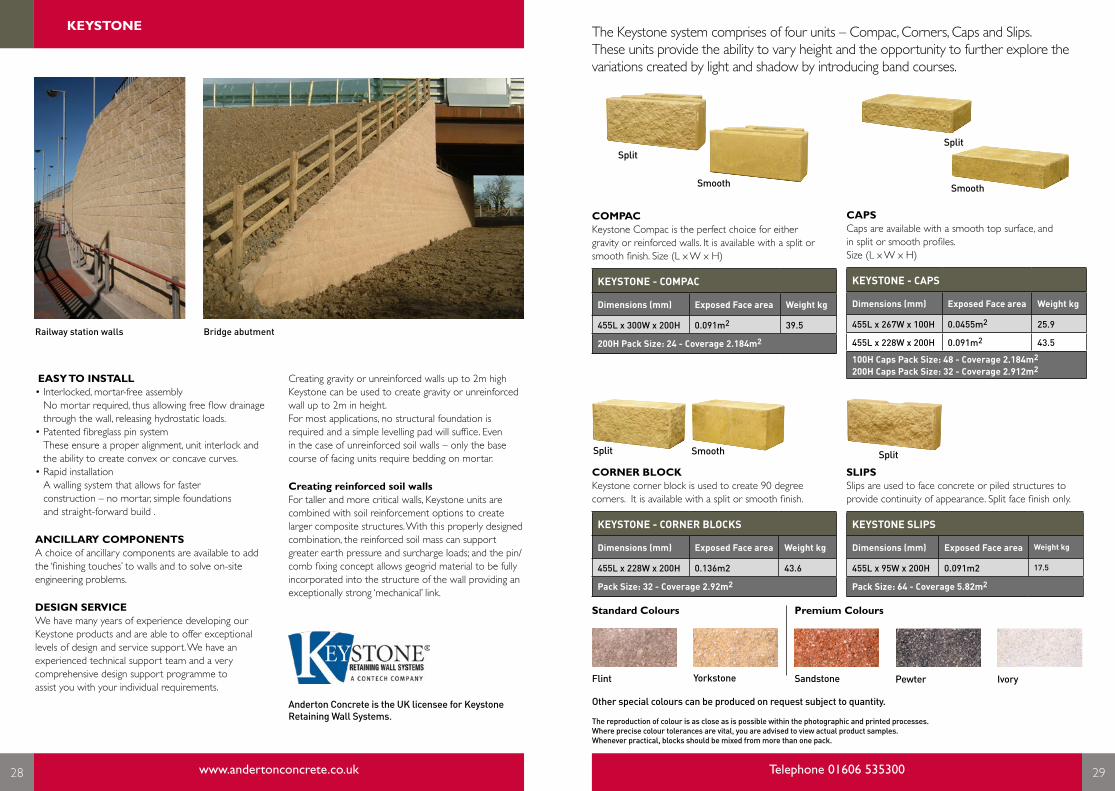
SLIPSSlips are used to face concrete or piled structures to provide continuity of appearance. Split face finish only.
KEYSTONE SLIPS
Dimensions (mm) Exposed Face area Weight kg
455L x 95W x 200H 0.091m2 17.5
Pack Size: 64 - Coverage 5.82m2
CORNER BLOCKKeystone corner block is used to create 90 degree corners. It is available with a split or smooth finish.
KEYSTONE - CORNER BLOCKS
Dimensions (mm) Exposed Face area Weight kg
455L x 228W x 200H 0.136m2 43.6
Pack Size: 32 - Coverage 2.92m2
The Keystone system comprises of four units – Compac, Corners, Caps and Slips. These units provide the ability to vary height and the opportunity to further explore the variations created by light and shadow by introducing band courses.
SplitSplit
Standard Colours Premium Colours
The reproduction of colour is as close as is possible within the photographic and printed processes. Where precise colour tolerances are vital, you are advised to view actual product samples.Whenever practical, blocks should be mixed from more than one pack.
Other special colours can be produced on request subject to quantity.
IvoryPewterYorkstone SandstoneFlint
Split Smooth
Smooth
Split
EASY TO INSTALL• Interlocked, mortar-free assembly
No mortar required, thus allowing free flow drainage through the wall, releasing hydrostatic loads.
• Patented fibreglass pin system These ensure a proper alignment, unit interlock and the ability to create convex or concave curves.
• Rapid installation A walling system that allows for faster construction – no mortar, simple foundations and straight-forward build .
ANCILLARY COMPONENTSA choice of ancillary components are available to add the ‘finishing touches’ to walls and to solve on-site engineering problems.
DESIGN SERVICEWe have many years of experience developing our Keystone products and are able to offer exceptional levels of design and service support. We have an experienced technical support team and a very comprehensive design support programme to assist you with your individual requirements.
Railway station walls Bridge abutment
CAPSCaps are available with a smooth top surface, and in split or smooth profiles.Size (L x W x H)
KEYSTONE - CAPS
Dimensions (mm) Exposed Face area Weight kg
455L x 267W x 100H 0.0455m2 25.9
455L x 228W x 200H 0.091m2 43.5
100H Caps Pack Size: 48 - Coverage 2.184m2
200H Caps Pack Size: 32 - Coverage 2.912m2Creating gravity or unreinforced walls up to 2m highKeystone can be used to create gravity or unreinforced wall up to 2m in height. For most applications, no structural foundation is required and a simple levelling pad will suffice. Even in the case of unreinforced soil walls – only the base course of facing units require bedding on mortar.
Creating reinforced soil wallsFor taller and more critical walls, Keystone units are combined with soil reinforcement options to create larger composite structures. With this properly designed combination, the reinforced soil mass can support greater earth pressure and surcharge loads; and the pin/comb fixing concept allows geogrid material to be fully incorporated into the structure of the wall providing an exceptionally strong ‘mechanical’ link.
COMPACKeystone Compac is the perfect choice for either gravity or reinforced walls. It is available with a split or smooth finish. Size (L x W x H)
KEYSTONE - COMPAC
Dimensions (mm) Exposed Face area Weight kg
455L x 300W x 200H 0.091m2 39.5
200H Pack Size: 24 - Coverage 2.184m2
Anderton Concrete is the UK licensee for Keystone Retaining Wall Systems.
KEYSTONE
28 www.andertonconcrete.co.uk Telephone 01606 535300 29
LINTELS

18 www.andertonconcrete.co.uk Telephone 01606 535300 19
CONCRETE BLOCK ANCILLARIES
30 www.andertonconcrete.co.uk Telephone 01606 535300 31
Beam and block flooring is the traditional and cost-effective suspended flooring system for ground and upper floors and Anderton Concrete now offers pre-cast ancillary products to complement this system.
Anderton Concrete coursing slips save a split brick course at side bearing or between end bearing.
CLOSURE BLOCK
COURSING SLIP
COURSING SLIPS
Product Code Length (mm) Width (mm) Height (mm) Weight kg Pack Size
COS03510N 385 100 35 2.3 228
COS04510N 385 100 45 2.9 204
COURSING BLOCKS
Product Code Length (mm) Width (mm) Height (mm) Weight kg Pack Size
COS06510N 440 100 65 6.5 234
COS09010N 440 100 90 8.1 160
CLOSURE BLOCKS
Product Length (mm) Width (mm) Height (mm) Weight kg Pack Size
TCL10010N 528 100 138 13.6 56
TCL14010N 528 140 138 19.4 56
TBL20510N 203 100 138 4.3 96
* Closure Blocks are available in 10N/mm2 strength as standard. For other strengths please contact Sales Office.
Anderton Concrete closure blocks are designed to fit between floor beams on the bearing ends. This saves cutting bricks or blocks when building the wall through the ends of the beams using standard centres.

18 www.andertonconcrete.co.uk Telephone 01606 535300 19
DELIVERY VEHICLE DETAILS
32 www.andertonconcrete.co.uk Telephone 01606 535300 33
Anderton Concrete works closely with a number of delivery partners to offer an efficient and on time service ensuring that our customers receive their products when they have requested.
TYPE A - Articulated Curtainsider• Available with and without Moffett forklift
• Readily available
• Delivery within 5 days
• Cannot be offloaded by crane
• Can carry 28 Tonnes of products if no offload required, 24 Tonnes if Moffett needed
• Approx. dimensions: Length 13.2m, Height 4.6m, Width 2.6m
TYPE B - Rigid Curtainsider• Available with and without Moffett forklift
• Readily available without offload
• Delivery within 5 days
• Can carry 14 Tonnes of products if no offload required, 10 Tonnes if Moffett needed
• Approx. dimensions: Length 10m, Height 4.6m, Width 2.6m
IMPORTANT NOTES
• Consideration must be given to anything that may restrict delivery to a site, from the size of the road, to height clearance (bridges and overhanging trees) and space for the vehicle to manoeuvre.
• In some cases sites can be so restrictive, an option to consider may be that of ordering through a merchant into their yard, and delivering on their vehicles.
• We want to deliver products to the best location for your project ON TIME, the FIRST TIME. If you are unsure of the requirements, contact your Area Sales Manager to arrange a site visit.
ALTERNATIVES
• We do have a number of stockists, and we are happy to provide details of the most convenient for you.
• We are happy for you to collect from our manufacturing plant, or indeed arrange your own transport to collect and deliver to your site if this is more convenient for you. Collection times are 7am to 3pm, Monday to Thursday, and until 2.30pm on Fridays.
• Our manufacturing plant’s address is: Bridle Way, Bootle, Merseyside, L30 4UA
TYPE C - Articulated Flat-Bed• Site must have offload – no offload available
with vehicle
• Delivery within 5 days
• Can be offloaded by crane
• Best for large projects with machinery on site
• Can carry 28 Tonnes of products
• Approx. dimensions: Length 16.5m, Height 4m, Width 2.4m
Moffett Forklift• Available with most vehicles
• Manoeuvrable and efficient offload facility
• Adds approx. 1.5m to overall vehicle length
For more information or a quotation for any of our products please contact us using the details below and one of our team will be happy to help.
HEAD OFFICEAnderton Concrete Products Limited (Cheshire) Units 1 & 2, Cosgrove Business Park Soot Hill, Anderton Northwich, Cheshire CW9 6AA
T: 01606 535300 (Structural) F: 01606 75905E: [email protected]
T: 01606 79436 (Fencing, Building & Rail Products) F: 01606 75899E: [email protected]
Specifier Mini Guides available on request...
MERSEYSIDEAnderton Concrete Products Limited (Merseyside)Bridle WayBootleMerseyside L30 4UA
PRODUCT GUIDE 2017
www.andertonconcrete.co.uk
FENCING BUILDING
PRODUCT GUIDE 2017
www.andertonconcrete.co.uk
Fencing & Building Rail
THE ENVIRONMENT
34 www.andertonconcrete.co.uk Telephone 01606 535300 35
CONTACT
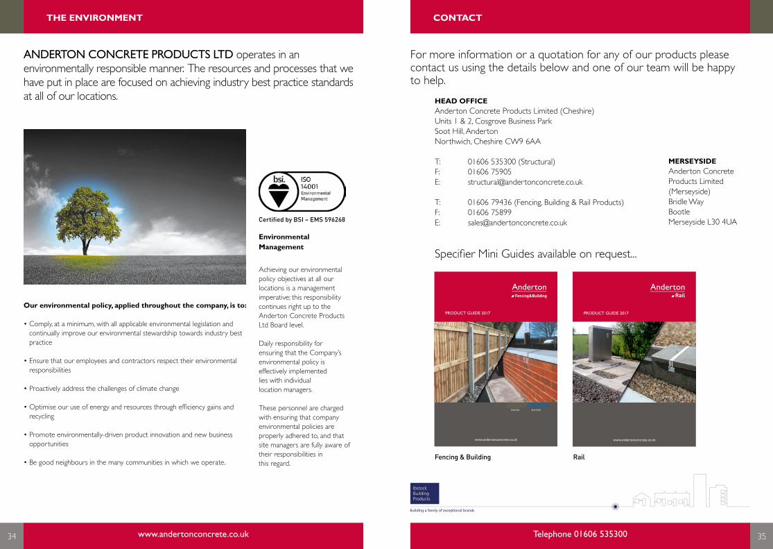
ANDERTON CONCRETE PRODUCTS LTD operates in an environmentally responsible manner. The resources and processes that we have put in place are focused on achieving industry best practice standards at all of our locations.
Our environmental policy, applied throughout the company, is to:
• Comply, at a minimum, with all applicable environmental legislation and continually improve our environmental stewardship towards industry best practice
• Ensure that our employees and contractors respect their environmental responsibilities
• Proactively address the challenges of climate change
• Optimise our use of energy and resources through efficiency gains and recycling
• Promote environmentally-driven product innovation and new business opportunities
• Be good neighbours in the many communities in which we operate.
Environmental Management
Achieving our environmental policy objectives at all our locations is a management imperative; this responsibility continues right up to the Anderton Concrete Products Ltd Board level.
Daily responsibility for ensuring that the Company’s environmental policy is effectively implemented lies with individual location managers.
These personnel are charged with ensuring that company environmental policies are properly adhered to, and that site managers are fully aware of their responsibilities in this regard.
Certified by BSI – EMS 596268

A: Anderton Wharf Units 1 & 2 Cosgrove Business Park Soot Hill Anderton Northwich Cheshire CW9 6AA
T: 01606 79436F: 01606 75899T: 01606 535300 StructuralF: 01606 75905 Structural
E: [email protected]: [email protected]: www.andertonconcrete.co.uk