
Leading Change Gemini Skills Workshop Gemini Consulting January 1999.

Copyright 2009 Carrier Corporation Form 38AKS-2PD
These dependable split systems match Carrier’s indoor-air handlers with outdoor condensing units for a wide selection of commercial cooling solutions. Units offer:• Pre-painted galvanized steel
cabinet• Optional E-coated air coil• Compressor unloading capability• UL and UL, Canada approvals
Features/BenefitsThe 38AKS units offer high unit EERs (Energy Efficiency Ratios), providing greater efficiency than similar units in the marketplace. This translates into year-round operating savings.Constructed for long lifeThe 38AKS units are designed and built to last. Cabinets are constructed of pre-painted galvanized steel, deliver-ing unparalleled protection against the environment. Inside and outside surfac-es are protected to ensure long life, good looks and reliable performance. The copper tube-aluminum fin outdoor coil construction provides long term re-liability and improved heat transfer. Where conditions require them, cop-per fin coils are available. For corrosive or coastal environments an epoxy bar-rier is available to provide superior coil durability.
GEMINI™38AKS028-044
Commercial Air-CooledSplit Systems
50/60 Hz
25 to 40 Nominal Tons(82.8 to 127.0 kW)
ProductData

2
ReliabilityThe 38AKS condensing units offer the building owner components and oper-ating controls designed for perfor-mance dependability. These condens-ing units feature the time proven highly reliable 06D and 06E compressors. Unloading capability for superior part load performance is a standard feature of these compressors.The compressor mounting system has vibration isolation to provide quiet op-eration and reduce component stress.
Each compressor is equipped with a crankcase heater to eliminate the oc-currence of liquid slugging at start-up.
The compressors also include an oil level sight glass for maintenance ease.The following safety features are included in each unit:• Anti short cycling control• Low oil pressure safety• Low refrigerant pressure safety• High refrigerant pressure safety• Calibrated circuit breakers
Constant volume and variable air volumeThe 38AKS condensing units feature one compressor and one refrigeration circuit. These units can be matched with a single air handler. Standard units are designed for con-stant volume control (CV). A standard
CV unit can be field converted to a variable air volume (VAV) unit by changing from pressure to electric un-loading and adding an accumulator. The VAV units feature electrically con-trolled compressor unloading to pre-cisely match unit capacity to building loads. The VAV equipped unit has a simple control interface for connection to a VAV discharge air control system.
Ease of installation and serviceThese units are equipped with hinged control box access panels, control in-terface terminal boards, liquid line shut off valves and compressor service valves.
Table of contentsPage
Features/Benefits . . . . . . . . . . . . . . . . . . . . . . . . . . . . . . . . . . . . . . . . . . .1,2Model Number Nomenclature . . . . . . . . . . . . . . . . . . . . . . . . . . . . . . . . . . . 3Capacity Ratings . . . . . . . . . . . . . . . . . . . . . . . . . . . . . . . . . . . . . . . . . . . . 4Physical Data . . . . . . . . . . . . . . . . . . . . . . . . . . . . . . . . . . . . . . . . . . . . . .5-7Options and Accessories . . . . . . . . . . . . . . . . . . . . . . . . . . . . . . . . . . . . . . . 8Dimensions . . . . . . . . . . . . . . . . . . . . . . . . . . . . . . . . . . . . . . . . . . . . . .9,10Selection Procedure . . . . . . . . . . . . . . . . . . . . . . . . . . . . . . . . . . . . . . . . . 11Performance Data . . . . . . . . . . . . . . . . . . . . . . . . . . . . . . . . . . . . . . . .12-25Typical Piping and Wiring . . . . . . . . . . . . . . . . . . . . . . . . . . . . . . . . . . .26,27Electrical Data . . . . . . . . . . . . . . . . . . . . . . . . . . . . . . . . . . . . . . . . . . . . . 28Controls . . . . . . . . . . . . . . . . . . . . . . . . . . . . . . . . . . . . . . . . . . . . . . . . . 29Typical Control Wiring Schematics. . . . . . . . . . . . . . . . . . . . . . . . . . . . .30-32Application Data . . . . . . . . . . . . . . . . . . . . . . . . . . . . . . . . . . . . . . . . .33,34Guide Specifications . . . . . . . . . . . . . . . . . . . . . . . . . . . . . . . . . . . . . . .35-37
Features/Benefits (cont)

3
Model number nomenclature
LEGEND
*Gross capacity based on 95 F air temperature entering condenser and45 F saturated suction temperature.
†Gross capacity based on 36 C air temperature entering condenser and8 C saturated suction temperature.
Al — AluminumCu — Copper
Quality Assurance
Certified to ISO 9001:2000
a38-7078
Unit Size - Nominal Tons* (kW†)
028 – 25 (88.0)034 – 30 (105.5)044 – 40 (140.7)
Packaging1 – Domestic with Bumper3 – Domestic with Top Crate
and Plastic Cover
38AKS 028 – – – 5 0 1 – –
38AKS – Commercial Air-CooledCondensing Units (Semi-Hermetic)
Not Used
Condenser Coil Fin Material – – Aluminum (Standard)C – Copper
K – Pre-Coated Aluminum Fins
E – E-Coated Al Fin/Cu TubeF – E-Coated Cu Fin/Cu Tube
Not Used
Revision Number0 – Original
Voltage Designation1 – 575-3-602 – 380-3-60 (Export Only)5 – 208/230-3-606 – 460-3-608 – 230-3-509 – 380/415-3-50
60 Hz 50 Hz
028 – 23.4 (82.8)034 – 26.5 (94.5)044 – 35.8 (127.0)
4
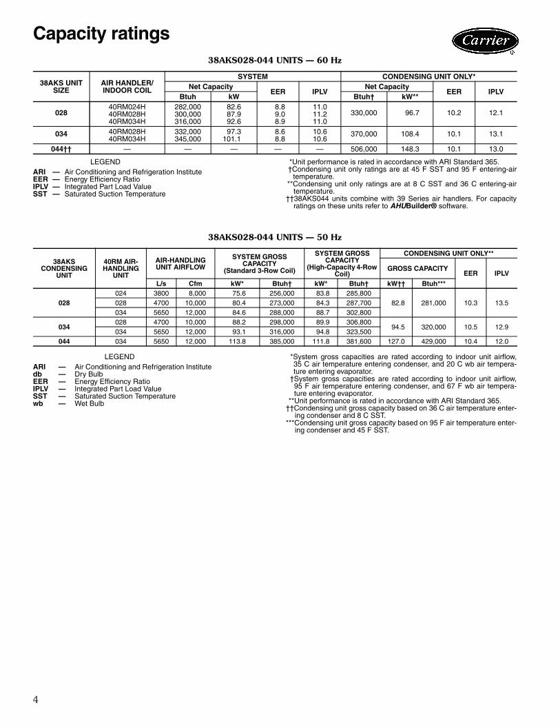
38AKS028-044 UNITS — 60 Hz
LEGEND *Unit performance is rated in accordance with ARI Standard 365.†Condensing unit only ratings are at 45 F SST and 95 F entering-air
temperature.**Condensing unit only ratings are at 8 C SST and 36 C entering-air
temperature.††38AKS044 units combine with 39 Series air handlers. For capacity
ratings on these units refer to AHUBuilder® software.
38AKS028-044 UNITS — 50 Hz
LEGEND *System gross capacities are rated according to indoor unit airflow,35 C air temperature entering condenser, and 20 C wb air tempera-ture entering evaporator.
†System gross capacities are rated according to indoor unit airflow,95 F air temperature entering condenser, and 67 F wb air tempera-ture entering evaporator.
**Unit performance is rated in accordance with ARI Standard 365.††Condensing unit gross capacity based on 36 C air temperature enter-
ing condenser and 8 C SST.***Condensing unit gross capacity based on 95 F air temperature enter-
ing condenser and 45 F SST.
38AKS UNIT SIZE
AIR HANDLER/INDOOR COIL
SYSTEM CONDENSING UNIT ONLY*Net Capacity
EER IPLVNet Capacity
EER IPLVBtuh kW Btuh† kW**
02840RM024H 282,000 82.6 8.8 11.0
330,000 96.7 10.2 12.140RM028H 300,000 87.9 9.0 11.240RM034H 316,000 92.6 8.9 11.0
034 40RM028H 332,000 97.3 8.6 10.6 370,000 108.4 10.1 13.140RM034H 345,000 101.1 8.8 10.6
044†† — — — — — 506,000 148.3 10.1 13.0
ARI — Air Conditioning and Refrigeration InstituteEER — Energy Efficiency RatioIPLV — Integrated Part Load ValueSST — Saturated Suction Temperature
38AKS CONDENSING
UNIT
40RM AIR-HANDLING
UNIT
AIR-HANDLING UNIT AIRFLOW
SYSTEM GROSS CAPACITY
(Standard 3-Row Coil)
SYSTEM GROSS CAPACITY
(High-Capacity 4-Row Coil)
CONDENSING UNIT ONLY**
GROSS CAPACITYEER IPLV
L/s Cfm kW* Btuh† kW* Btuh† kW†† Btuh***
028024 3800 8,000 75.6 256,000 83.8 285,800
82.8 281,000 10.3 13.5028 4700 10,000 80.4 273,000 84.3 287,700034 5650 12,000 84.6 288,000 88.7 302,800
034028 4700 10,000 88.2 298,000 89.9 306,800
94.5 320,000 10.5 12.9034 5650 12,000 93.1 316,000 94.8 323,500
044 034 5650 12,000 113.8 385,000 111.8 381,600 127.0 429,000 10.4 12.0
ARI — Air Conditioning and Refrigeration Institutedb — Dry BulbEER — Energy Efficiency RatioIPLV — Integrated Part Load ValueSST — Saturated Suction Temperaturewb — Wet Bulb
Capacity ratings

5
38AKS028-044 UNITS — 60 Hz, ENGLISH
LEGEND
*Unit is factory-supplied with nitrogen holding charge only.†Typical operating charge with 25 ft of interconnected piping. Operating charge is approximate for maximum system capacity.
**Storage capacity is 80% full at liquid saturated temperature of 125 F.
UNIT 38AKS 028 034 044NOMINAL CAPACITY (tons) 25 30 40OPERATING WEIGHTS (lb)
With Aluminum-Fin Coils (standard) 1650 1803 2437With Copper-Fin Coils (optional) 1804 2009 2745
REFRIGERANT* R-22Operating Charge, Typical (lb)† 30.5 43.5 65.0
COMPRESSOR Reciprocating, Semi-HermeticQty...Model 1...06E9265 1...06E9275 1...06E9299Oil Charge (pt) 20 20 19No. Cylinders 6 6 6Speed (rpm) 1750Capacity Steps (%) 100, 66, 33Unloader Setting (psig)
No. 1 Load 76Unload 58
No. 2 Load 78Unload 60
Crankcase Heater Watts 180CONDENSER FANS Propeller Type — Direct Drive
Qty...Rpm 2...1140 3...1140Diameter (in.) 30Nominal Hp 1.0Nominal Airflow (cfm total) 15,700 15,700 23,700Watts (total) 1490 1750 1520
CONDENSER COIL Enhanced Copper Tubes, Lanced Aluminum FinsRows...Fins/in. 2...19 3...17 3...17Face Area (sq ft) 39.2 39.2 58.4Storage Capacity (lb)** 37.7 56.6 84.4
CONTROLSPressurestat (psig)High-Pressure
Open 426 ± 7Close 320 ± 20
Low-PressureOpen 27 ± 3Close 44 ± 5
Oil Pressure (psi)Open 6.2Close 9.0
FAN CYCLING CONTROLSOperating Pressure (psig)No. 2 Fan, Close 255 ± 10
Open 160 ± 10PRESSURE RELIEF Fusible Plug
Location Liquid and Suction LineTemperature (F) 210
PIPING CONNECTIONS (in. ODM)Suction 15/8 21/8 21/8Liquid 7/8Hot Gas Stub 5/8
ODM — Outside Diameter, Male
Physical data

6
38AKS028-044 UNITS — 50 Hz, ENGLISH
LEGEND
*Based on operation at 45 F saturated suction temperature and 95 Foutdoor ambient.
†Unit is factory-supplied with nitrogen holding charge only.**Typical operating charge with 25 ft of interconnecting piping.
††Storage capacity of condenser coil with coil 80% full of liquid R-22 at125 F.
UNIT 38AKS 028 034 044NOMINAL CAPACITY (tons)* 23.4 26.5 35.8OPERATING WEIGHTS (lb)
With Aluminum-Fin Coils (Standard) 1650 1803 2437With Copper-Fin Coils (Optional) 1804 2009 2745
REFRIGERANT† R-22Operating Charge, Typical (lb)** 30.5 43.5 65.0
COMPRESSOR Reciprocating, Semi-HermeticQty...Model 1...06E9265 1...06E9275 1...06E9299No. Cylinders (ea) 6 6 6Speed (rpm) 1450Oil Charge (pt) 20.0 20.0 19.0Capacity Steps 100%, 66%, 33%Unloader Setting (psig)
No. 1 Load 76Unload 58
No. 2 Load 78Unload 60
Crankcase Heater Watts 180CONDENSER FANS Propeller Type — Direct Drive
Qty...Speed (Rpm) 2...950 3...950Diameter (in.) 30Nominal Hp 1.0Nominal Airflow (cfm total) 15,700 15,700 23,700Watts (Total) 1490 1750 1520
CONDENSER COIL Enhanced Copper Tubes, Lanced Aluminum FinsRows...Fins/in. 2...19 3...17 3...17Face Area (sq ft) 39.2 39.2 58.4Storage Capacity (lb)†† 37.7 56.6 84.4
CONTROLSPressurestat (psig)High-Pressure Switch
Open 426 ± 7Close 320 ± 20
Low-Pressure SwitchOpen 27 ± 3Close 44 ± 5
Oil Pressure SwitchOpen 6.2Close 9.0
FAN CYCLING CONTROLSOperating Pressure (psig)
No. 2 Fan, Close 255 ± 10Open 160 ± 10
PRESSURE RELIEF Fusible PlugLocation Liquid and Suction LineTemperature (F) 210
PIPING CONNECTIONS (in. ODM)Suction 15/8 21/8 21/8Liquid 7/8Hot Gas Stub 5/8
ODM — Outside Diameter, Male
Physical data (cont)
7
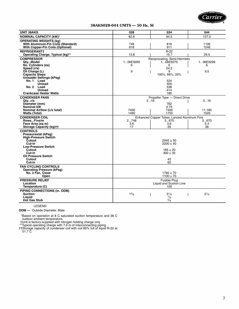
38AKS028-044 UNITS — 50 Hz, SI
LEGEND
*Based on operation at 8 C saturated suction temperature and 36 Coutdoor ambient temperature.
†Unit is factory-supplied with nitrogen holding charge only.**Typical operating charge with 7.6 m of interconnecting piping.
††Storage capacity of condenser coil with coil 80% full of liquid R-22 at51.7 C.
UNIT 38AKS 028 034 044NOMINAL CAPACITY (kW)* 82.8 94.5 127.0OPERATING WEIGHTS (kg)
With Aluminum-Fin Coils (Standard) 748 818 1106With Copper-Fin Coils (Optional) 818 911 1246
REFRIGERANT† R-22Operating Charge, Typical (kg)** 13.8 19.7 29.5
COMPRESSOR Reciprocating, Semi-HermeticQty...Model 1...06E9265 1...06E9275 1...06E9299No. Cylinders (ea) 6 6 6Speed (r/s) 24.2Oil Charge (L) 9 9 9.5Capacity Steps 100%, 66%, 33%Unloader Settings (kPag)
No. 1 Load 524Unload 400
No. 2 Load 538Unload 414
Crankcase Heater Watts 180CONDENSER FANS Propeller Type — Direct Drive
Qty...r/s 2...16 3...16Diameter (mm) 762Nominal kW 0.75Nominal Airflow (L/s total) 7400 7400 11,180Watts (Total) 1490 1750 1520
CONDENSER COIL Enhanced Copper Tubes, Lanced Aluminum FinsRows...Fins/m 2...748 3...670 3...670Face Area (sq m) 3.6 3.6 5.4Storage Capacity (kg)†† 17 26 38
CONTROLSPressurestat (kPag)High-Pressure Switch
Cutout 2940 ± 50Cut-in 2200 ± 40
Low-Pressure SwitchCutout 185 ± 20Cut-in 300 ± 35
Oil Pressure SwitchCutout 43Cut-in 62
FAN CYCLING CONTROLSOperating Pressure (kPag)
No. 2 Fan, Close 1760 ± 70Open 1100 ± 70
PRESSURE RELIEF Fusible PlugLocation Liquid and Suction LineTemperature (C) 100
PIPING CONNECTIONS (in. ODM)Suction 15/8 21/8 21/8Liquid 7/8Hot Gas Stub 5/8
ODM — Outside Diameter, Male

8
Factory-installed optionsEnviro-Shield™ condenser options are available tomatch coil protection to site conditions for optimum dura-bility. See table below and refer to the Application Data forselection guidance. Consult your Carrier representative forfurther information.
Field-installed accessoriesElectric unloader package includes hardware and sole-noid valve to convert a pressure-operated unloader to elec-tric unloading.Motormaster® –20 F (–29 C) low-ambient controlscontrols outdoor-fan motor operation to maintain the cor-rect head pressure at low outdoor ambient temperatures.Only one low ambient temperature kit is required per unit.Gage panel package provides a suction and a dischargepressure gage for the refrigerant circuit.
ModuPanel™ VAV controller allows systems to operateas VAV (variable air volume) systems. The controller in-cludes a microprocessor, satellite sequencer, 4 status lights,5-hour bypass timer, and locked enclosure.Hot-gas bypass kit prevents the indoor coil from freez-ing up during low airflow or low return-air temperature ap-plications by maintaining minimum suction pressure.Suction line accumulator can be provided for VAV,VVT® (variable volume and temperature), or long line CVapplications.PremierLink controller is a field-retrofit split systemcontrol compatible with the Carrier Comfort Network®
(CCN) system.Part-winding-start timing relay reduces inrush currentand locked rotor amps on start-up. This accessory may re-quire a special-order unit. See table below.
PART-WINDING-START TABLE
NOTES:1. Can be field modified to part winding start by adding a time delay
relay (part no. HN67ZA001). 2. Requires special order to change circuit breakers and contactors.3. Requires special order to change circuit breakers and contactors,
and cannot use triple-voltage compressor.
CONDENSER COIL OPTIONS
LEGEND *See “Selection Guide: Environmental Corrosion Protection” CatalogNo. 04-581006-01 for more information.
ITEMFACTORY-
INSTALLED OPTION
FIELD-INSTALLED
ACCESSORYEnviro-Shield™ Condenser Options X–20 F (-29 C) Low-Ambient Controls XGage Panel Package XPremierLink™ Controller XElectric Unloader Package XModuPanel™ Control XHot-Gas Bypass Kit XSuction Line Accumulator XPart-Winding-Start Timing Relay X
UNIT SIZE38AKS
VOLTAGE (60 Hz)208/230 380 460 575
028Note 1 Note 2 Note 3 Note 2034
044
COPPER-TUBE COILSWITH ENVIRO-SHIELD
OPTION*
ENVIRONMENT
Standard MildCoastal
ModerateCoastal
SevereCoastal Industrial Combined
Industrial/CoastalAl Fins (Standard Coils) XCu Fins XAl Fins, E-Coating XCu Fins, E-Coating X XAl Fins, Pre-coated X
Al — AluminumCu — CopperEnviro-Shield — Family of Coil Protection OptionsE-Coated — Epoxy coating Applied to Entire Coil AssemblyPre-Coated — Epoxy coating Applied to Fin Stock Material
Options and accessories

9
Dimensions38A
KS028,0
34 U
NIT
S
2'-4
"C
EN
TER
OF
GR
AVIT
Y
CE
NTE
R O
F G
RAV
ITY
CLE
AR
AN
CE
TO
WA
LL O
R N
EX
T U
NIT
ACC
ES
S P
AN
EL
5'-8
"
CLE
AR
AN
CE
TO
WA
LL O
R N
EX
T U
NIT
2 1/
8"
WO
RK
ING
CLE
AR
AN
CE
PE
R N
EC
110-
16
4'-0
"
ACC
ESS
PAN
ELAC
CE
SS
PA
NE
L
ACC
ES
S P
AN
EL
ACC
ESS
DO
OR
HIN
GE
D
LIQ
UID
LIN
E C
ON
NE
CTI
ON
7/8"
O.D
.
SU
CTI
ON
LIN
E C
ON
NE
CTI
ON
1 5/
8" O
.D. (
028)
2 1/
8" O
.D. (
034)
MTG
. HO
LES
HIN
GE
D A
CC
ES
S D
OO
R
[63.
5]2
1/2"
DIA
.LI
FTIN
G
3/4"
DIA
.
[22.
2]
[63.
5-92
.1]
FIE
LD P
OW
ER
FIE
LD C
ON
TRO
L
2 1/
2"-3
5/8
" DIA
.
EN
TRY
& L
IFTI
NG
7/8"
DIA
. (2)
PO
WE
R E
NTR
Y
(TY
P 4
PLA
CE
S)
MO
UN
TIN
G H
OLE
S
[19.
1]
AIR
FLO
W T
HR
UC
ON
DE
NS
ER
[22.
2] 7
/8" D
IA.
[63.
5-92
.1] 2
1/2
"-3
5/8"
DIA
.
FIE
LD C
ON
TRO
L C
IRC
UIT
WIR
ING
FIE
LD M
AIN
PO
WE
R S
UP
PLY
CO
NTR
OL
BO
X
FOR
K T
RU
CK
LIFT
PO
CK
ETS
FOR
K T
RU
CK
LIFT
PO
CK
ETS
[22.
2]7/
8" D
IA.
V.A.
VP
OW
ER
EN
TRY
ACC
ES
S D
OO
R
BO
TH S
IDE
S
[711
]
[109
2] 3
'-7"
[121
9] 4
'-0"
[172
6]
[121
9] 4
'-0"
[54]
[121
9]
1413
[4'-7
5/8
"]
[81]
3 3/
16"
[113
8]3'
-8 1
3/16
"
[80]
3 1/
8"
[142
]
[324
7]10
'-7 1
3/16
"
[766
]2'
-6 5
/32"
[100
9]3'
-3 3
/4"
[208
]
[766
]2'
-6 1
/8"
[180
]7
1/16
"
[806
]
[241
][3
44]
[188
0]6'
-2"
[346
]1'
-1 5
/8"
[61]
2 7/
16"
[161
9]5'
-3 3
/4"
[235
]9
1/4"
[174
2]5'
-8 9
/16"
[131
5]4'
-3 3
/4"
[100
]3
15/1
6"
[40]
1 9/
16"
[205
7]6'
-9"
EN
D V
IEW
SID
E V
IEW
TO
P V
IEW
CO
MP
R S
EC
TIO
N
FA
N N
o. 1
FA
N N
o. 2
5 19
/32"
8 3/
16"
2'-7
3/4
"
9 1/
2"1'
-1 9
/16"
LEG
EN
D
NO
TE
S:
1.T
here
mus
t be
a m
inim
um o
f 8
ft [2
440
mm
] of
cle
ar a
irsp
ace
abov
e un
it.2.
The
app
roxi
mat
e op
erat
ing
wei
ght o
f the
uni
t is:
NO
TE
: A
“C
” in
mod
el n
umbe
r in
dica
tes
unit
has
optio
nal
fact
ory-
inst
alle
d co
pper
-fin
coi
l.3.
Dim
ensi
ons
in [
] are
mill
imet
ers.
NE
C—
Nat
iona
l Ele
ctri
cal C
ode
VAV
—V
aria
ble
Air
Vol
ume
UN
IT38
AK
SW
EIG
HT,
lb [
kg]
028
1650
[748
]02
8C18
04 [8
18]
034
1803
[818
]03
4C20
09 [9
11]
a38-7048

10
Dimensions (cont)38A
KS044 U
NIT
a38-7049
2'-6
1/2
"C
EN
TER
OF
GR
AVIT
Y
CE
NTE
R O
F G
RAV
ITY
CLE
AR
AN
CE
TO
WA
LL O
R N
EX
T U
NIT
ACC
ES
S P
AN
EL
CLE
AR
AN
CE
TO
WA
LL O
R N
EX
T U
NIT
5'-8
"
2 1/
8"
WO
RK
ING
CLE
AR
AN
CE
PE
R N
EC
110-
16
4'-0
"
ACC
ES
S P
AN
EL
ACC
ES
S P
AN
EL
ACC
ESS
PAN
ELH
ING
ED
AC
CE
SS
DO
OR
ACC
ESS
DO
OR
HIN
GED
LIQ
UID
LIN
EC
ON
NE
CTI
ON
7/8"
O.D
.
SU
CTI
ON
LIN
EC
ON
NE
CTI
ON
2 1/
8" O
.D.CO
NTR
OL
BO
X
[63.
5]2
1/2"
DIA
.LI
FTIN
G
3/4"
DIA
.
[22.
2][6
3.5-
92.1
]
FIE
LD P
OW
ER
FIE
LD C
ON
TRO
L
2 1/
2"-3
5/8
" DIA
.
EN
TRY
& L
IFTI
NG
7/8"
DIA
. (2)
PO
WE
R E
NTR
Y
(TY
P 4
PLA
CE
S)
MO
UN
TIN
G H
OLE
S
[19.
1]
AIR
FLO
W T
HR
UC
ON
DE
NS
ER
[22.
2] 7
/8" D
IA.
[63.
5-92
.1] 2
1/2
"-3
5/8"
DIA
.
FIE
LD C
ON
TRO
L C
IRC
UIT
WIR
ING
FIE
LD M
AIN
PO
WE
R S
UP
PLY
MTG
. HO
LES
FOR
K T
RU
CK
LIFT
PO
CK
ETS
FOR
K T
RU
CK
LIFT
PO
CK
ETS
ACC
ES
S D
OO
R
BO
TH S
IDE
S
[775
]
[124
5] 4
'-1"
[121
9] 4
'-0"
[121
9] 4
'-0"
[172
6]
[54]
[121
9]
1413
[4'-7
5/8
"]
[442
4]
14'-6
1/8
"
[80]
3 1/
8"
[142
]
[766
]2'
-6 5
/32"
[81]
3 3/
16"
[113
8]3'
-8 1
3/16
"
[100
9]3'
-3 3
/4"
[208
]
[766
]
2'-6
1/8
"[1
80]
7 1/
16"
[131
5]4'
-3 3
/4"
[806
]2'
-7 3
/4"
[241
]9
1/2"
1'-1
9/1
6"[4
52]
[346
]1'
-1 5
/8"
[266
7]8'
-9"
[322
5]10
'-7"
[61]
2 7/
16"
[161
9]5'
-3 3
/4"
[235
]9
1/4"
[174
2]
5'-8
9/1
6"
[100
]3
15/1
6"
[40]
1 9/
16"
EN
D V
IEW
SID
E V
IEW
TO
P V
IEW
CO
MP
R S
EC
TIO
N
FA
N N
o. 1
FA
N N
o. 2
FA
N N
o. 3
5 19
/32"
8 3/
16"
NO
TE
S:
1.T
here
mus
t be
a m
inim
um o
f 8 ft
[244
0 m
m] o
f cle
ar a
irsp
ace
abov
e un
it.2.
The
app
roxi
mat
e op
erat
ing
wei
ght o
f the
uni
t is:
NO
TE
: A
“C
” in
m
odel
nu
mbe
r in
dica
tes
unit
has
optio
nal f
acto
ry-in
stal
led
copp
er-f
in c
oil.
UN
IT38
AK
SW
EIG
HT,
lb [
kg]
044
2437
[110
6]04
4C27
45 [1
246]
11
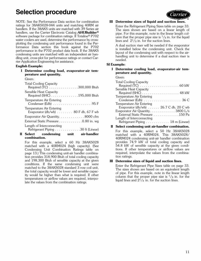
NOTE: See the Performance Data section for combinationratings for 38AKS028-044 units and matching 40RM airhandlers. If the 38AKS units are matched with 39 Series airhandlers, use the Carrier Electronic Catalog AHUBuilder®
software package for combination ratings. If Totaline® P702water coolers are used, determine the performance by cross-plotting the condensing unit performance found in the Per-formance Data section this book against the P702performance in the P702 product data book. If the 38AKScondensing units are matched with an independent air han-dling unit, cross-plot for performance ratings or contact Car-rier Application Engineering for assistance.English Example:
I Determine cooling load, evaporator-air tem-perature and quantity.Given:Total Cooling Capacity
Required (TC) . . . . . . . . . . . . . . .300,000 BtuhSensible Heat Capacity
Required (SHC) . . . . . . . . . . . . . .195,000 BtuhTemperature Air Entering
Condenser (Edb) . . . . . . . . . . . . . . . . . . . .95 FTemperature Air Entering
Evaporator (db/wb) . . . . . . . . 80 F db, 67 F wbEvaporator Air Quantity. . . . . . . . . . . . . 8000 cfmExternal Static Pressure . . . . . . . . . . . .0.80 in. wgLength of Interconnecting
Refrigerant Piping . . . . . . . . . . . . .30 ft (Linear)II Select condensing unit air-handler
combination.For this example, select a 60 Hz 38AKS028matched with a 40RM024 (high capacity). (SeeCondensing Unit Combination Ratings table onpage 13.) This condensing unit-air handler combina-tion provides 318,900 Btuh of total cooling capacityand 198,300 Btuh of sensible capacity at the givenconditions. If the same condensing unit werematched to the 38AKS028 standard 3 row coil unit,the total capacity would be lower and sensible capac-ity would be higher than what is required. If othertemperatures or airflow values are required, interpo-late the values from the combination ratings.
III Determine sizes of liquid and suction lines.Enter the Refrigerant Piping Sizes table on page 33.The sizes shown are based on a linear length ofpipe. For this example, note in the linear length col-umn that the proper pipe size is 7/8 in. for the liquidlines and 21/8 in. for the suction lines.A dual suction riser will be needed if the evaporatoris installed below the condensing unit. Check thelayout of the condensing unit with respect to the air-handling unit to determine if a dual suction riser isneeded.
SI Example:I Determine cooling load, evaporator-air tem-
perature and quantity.Given:Total Cooling Capacity
Required (TC) . . . . . . . . . . . . . . . . . . . . 60 kWSensible Heat Capacity
Required (SHC) . . . . . . . . . . . . . . . . . . . 48 kWTemperature Air Entering
Condenser (Edb) . . . . . . . . . . . . . . . . . . . 36 CTemperature Air Entering
Evaporator (db/wb) . . . . . . 26.7 C db, 20 C wbEvaporator Air Quantity. . . . . . . . . . . . . 3800 L/s
External Static Pressure . . . . . . . . . . . . .150 PaLength of Interconnecting
Refrigerant Piping . . . . . . . . . . . . 18 m (Linear)II Select condensing unit air-handler combination.
For this example, select a 50 Hz 38AKS028matched with a 40RM024. This 38AKS028/40RM024 condensing unit-air handler combinationprovides 74.9 kW of total cooling capacity and54.8 kW of sensible capacity at the given condi-tions. If other temperatures or airflow values arerequired, interpolate the values from the combina-tion ratings.
III Determine sizes of liquid and suction lines.Enter the Refrigerant Pipe Sizes table on page 33.The sizes shown are based on an equivalent lengthof pipe. For this example, note in the linear lengthcolumn that the proper pipe size is 7/8 in. for theliquid lines and 21/8 in. for the suction lines.
Selection procedure
12
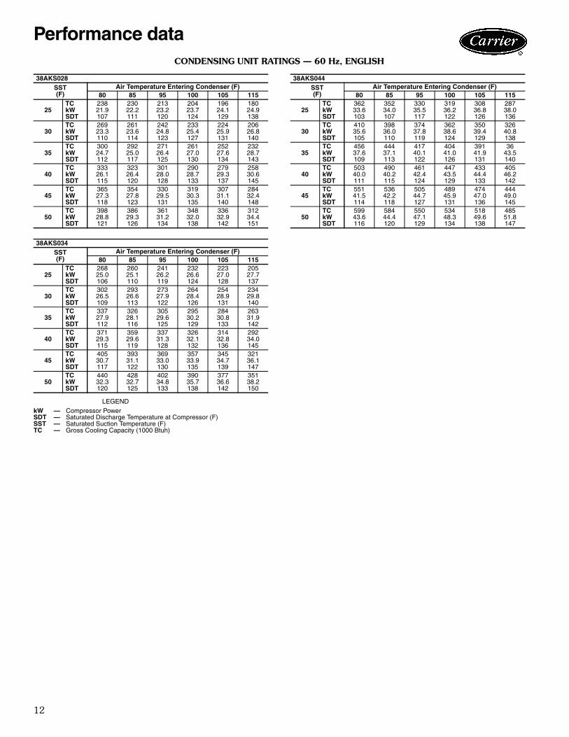
CONDENSING UNIT RATINGS — 60 Hz, ENGLISH
LEGEND
38AKS028SST(F)
Air Temperature Entering Condenser (F)80 85 95 100 105 115
25TC 238 230 213 204 196 180kW 21.9 22.2 23.2 23.7 24.1 24.9SDT 107 111 120 124 129 138
30TC 269 261 242 233 224 206kW 23.3 23.6 24.8 25.4 25.9 26.8SDT 110 114 123 127 131 140
35TC 300 292 271 261 252 232kW 24.7 25.0 26.4 27.0 27.6 28.7SDT 112 117 125 130 134 143
40TC 333 323 301 290 279 258kW 26.1 26.4 28.0 28.7 29.3 30.6SDT 115 120 128 133 137 145
45TC 365 354 330 319 307 284kW 27.3 27.8 29.5 30.3 31.1 32.4SDT 118 123 131 135 140 148
50TC 398 386 361 348 336 312kW 28.8 29.3 31.2 32.0 32.9 34.4SDT 121 126 134 138 142 151
38AKS034SST(F)
Air Temperature Entering Condenser (F)80 85 95 100 105 115
25TC 268 260 241 232 223 205kW 25.0 25.1 26.2 26.6 27.0 27.7SDT 106 110 119 124 128 137
30TC 302 293 273 264 254 234kW 26.5 26.6 27.9 28.4 28.9 29.8SDT 109 113 122 126 131 140
35TC 337 326 305 295 284 263kW 27.9 28.1 29.6 30.2 30.8 31.9SDT 112 116 125 129 133 142
40TC 371 359 337 326 314 292kW 29.3 29.6 31.3 32.1 32.8 34.0SDT 115 119 128 132 136 145
45TC 405 393 369 357 345 321kW 30.7 31.1 33.0 33.9 34.7 36.1SDT 117 122 130 135 139 147
50TC 440 428 402 390 377 351kW 32.3 32.7 34.8 35.7 36.6 38.2SDT 120 125 133 138 142 150
kW — Compressor PowerSDT — Saturated Discharge Temperature at Compressor (F)SST — Saturated Suction Temperature (F)TC — Gross Cooling Capacity (1000 Btuh)
38AKS044SST(F)
Air Temperature Entering Condenser (F)80 85 95 100 105 115
25TC 362 352 330 319 308 287kW 33.6 34.0 35.5 36.2 36.8 38.0SDT 103 107 117 122 126 136
30TC 410 398 374 362 350 326kW 35.6 36.0 37.8 38.6 39.4 40.8SDT 105 110 119 124 129 138
35TC 456 444 417 404 391 36 kW 37.6 37.1 40.1 41.0 41.9 43.5SDT 109 113 122 126 131 140
40TC 503 490 461 447 433 405kW 40.0 40.2 42.4 43.5 44.4 46.2SDT 111 115 124 129 133 142
45TC 551 536 505 489 474 444kW 41.5 42.2 44.7 45.9 47.0 49.0SDT 114 118 127 131 136 145
50TC 599 584 550 534 518 485kW 43.6 44.4 47.1 48.3 49.6 51.8SDT 116 120 129 134 138 147
Performance data

13
CONDENSING UNIT COMBINATION RATINGS — 60 Hz, ENGLISH
38AKS028 UNIT
LEGEND NOTES:1. Direct interpolation is permissible. Do not extrapolate. 2. Evaporator fan heat not deducted from ratings.3. Ratings based on approximately 12 F superheat leaving coil.4. Formulas:
Where hewb = enthalpy of air entering coil.5. SHC is based on 80 F db temperature of air-entering evaporator coil.
38AKS028/40RM024 WITH STANDARD 3-ROW COIL
Temp (F)Air EnteringCondenser
(Edb)
Evaporator Air — Cfm6000 8000 10,000
Evaporator Air — Ewb (F)72 67 62 72 67 62 72 67 62
85TC 305.1 279.8 — 320.3 295.8 — 330.3 305.7 279.5SHC 150.5 184.8 — 167.6 213.3 — 183.0 239.4 279.5kW 25.59 24.45 — 26.28 25.17 — 26.73 25.62 24.44
95TC 292.8 268.8 — 306.8 283.5 257.9 315.7 292.9 269.6SHC 145.8 180.3 — 162.7 208.1 257.9 177.8 233.6 269.6kW 27.58 26.34 — 28.30 27.09 25.77 28.76 27.58 26.38
100TC 286.3 262.5 237.6 300.0 276.8 252.2 308.6 286.1 263.9SHC 143.3 177.7 227.0 160.3 205.3 252.2 175.3 230.5 263.9kW 28.50 27.18 25.81 29.25 27.97 26.61 29.72 28.49 27.26
105TC 279.8 256.7 232.8 292.9 270.3 247.1 300.9 279.4 258.6SHC 140.8 175.3 222.8 157.7 202.5 247.1 172.6 227.4 258.6kW 29.35 27.86 26.33 30.19 28.74 27.25 30.71 29.32 27.99
115TC 266.8 245.0 223.2 278.7 257.4 236.9 285.7 265.9 248.0SHC 135.9 170.5 214.4 152.6 197.1 236.9 167.3 221.3 248.0kW 31.21 29.70 28.19 32.03 30.56 29.14 32.52 31.15 29.91
38AKS028/40RM028 WITH STANDARD 3-ROW COIL
Temp (F)Air EnteringCondenser
(Edb)
Evaporator Air — Cfm7500 10,000 12,500
Evaporator Air — Ewb (F)72 67 62 72 67 62 72 67 62
85TC 330.8 305.4 277.1 344.8 318.8 293.3 353.4 329.1 307.4SHC 168.9 212.4 270.1 189.8 245.6 293.3 209.5 275.9 307.3kW 26.75 25.61 24.33 27.39 26.21 25.06 27.77 26.67 25.69
95TC 316.6 292.0 266.5 329.6 304.5 282.3 337.3 314.4 295.9SHC 163.7 207.0 260.4 184.4 239.8 282.3 204.1 269.5 295.9kW 28.81 27.54 26.22 29.48 28.18 27.03 29.88 28.69 27.73
100TC 309.7 285.0 260.4 322.5 297.3 276.3 329.8 307.2 289.9SHC 161.2 204.2 254.8 181.9 236.8 276.3 201.6 266.4 289.9kW 29.79 28.42 27.07 30.49 29.10 27.94 30.90 29.65 28.69
105TC 302.3 277.9 254.8 314.5 289.8 270.4 321.4 299.5 283.8SHC 158.4 201.3 249.7 179.1 233.7 270.4 198.8 263.0 283.7kW 30.80 29.23 27.75 31.58 29.99 28.75 32.03 30.62 29.61
115TC 287.5 264.0 243.6 298.6 274.9 258.7 304.6 284.3 271.5SHC 153.0 195.7 239.4 173.5 227.6 258.7 193.2 256.4 271.5kW 32.64 31.01 29.60 33.41 31.77 30.65 33.83 32.42 31.53
38AKS028/40RM034 WITH STANDARD 3-ROW COIL
Temp (F)Air EnteringCondenser
(Edb)
Evaporator Air — Cfm9000 12,000 15,000
Evaporator Air — Ewb (F)72 67 62 72 67 62 72 67 62
85TC 353.9 325.8 300.2 367.2 339.2 318.4 374.7 350.2 378.8SHC 186.0 238.4 293.9 212.4 276.3 318.4 234.9 311.5 272.3kW 27.80 26.53 25.37 28.40 27.13 26.19 28.74 27.63 28.92
95TC 337.9 310.6 288.0 350.0 323.1 305.6 356.7 333.7 327.6SHC 179.9 232.4 282.8 206.6 269.8 305.6 228.9 304.2 309.3kW 29.91 28.50 27.33 30.53 29.14 28.24 30.88 29.69 29.37
100TC 330.6 303.1 281.4 342.4 315.4 299.1 348.8 326.0 305.6SHC 177.2 229.4 276.8 204.0 266.7 299.1 226.3 300.9 325.3kW 30.94 29.42 28.23 31.59 30.10 29.20 31.94 30.69 29.56
105TC 322.2 295.2 274.9 333.4 307.1 292.3 339.4 317.4 283.3SHC 174.0 226.2 270.9 210.0 263.4 292.3 223.1 297.1 341.4kW 32.08 30.34 29.04 32.80 31.10 30.15 33.19 31.77 29.57
115TC 305.6 279.5 262.0 315.7 290.5 278.7 — 300.4 244.7SHC 167.7 220.0 259.2 195.0 256.7 278.7 — 289.6 369.4kW 33.90 32.09 30.88 34.59 32.85 32.04 — 33.54 29.68
— — Out of RangeEdb — Entering Dry BulbEwb — Entering Wet BulbkW — Compressor Motor Power InputSHC — Sensible Heat Capacity (1000 Btuh) GrossTC — Total Capacity (1000 Btuh) Gross
38AKS028/40RM024 WITH HIGH-CAPACITY 4-ROW COIL
Temp (F)Air EnteringCondenser
(Edb)
Evaporator Air — Cfm6000 8000 10,000
Evaporator Air — Ewb (F)72 67 62 72 67 62 72 67 62
85TC 341.7 312.2 284.6 364.1 333.8 304.9 377.8 347.4 318.6SHC 133.1 175.5 216.7 149.5 203.1 255.5 164.0 228.6 290.8kW 28.00 26.64 25.34 29.05 27.67 26.34 29.67 28.31 26.97
95TC 327.7 299.3 272.7 347.9 318.9 291.2 360.7 331.7 303.8SHC 128.9 170.8 211.9 144.6 198.3 250.0 159.7 223.9 284.9kW 29.94 28.46 27.02 31.03 29.51 28.04 31.68 30.19 28.73
100TC 320.6 292.8 266.6 339.7 311.4 284.4 352.3 323.8 296.9SHC 126.7 168.7 209.4 142.6 196.0 247.7 157.7 221.7 282.1kW 30.92 29.38 27.88 32.01 30.43 28.91 32.71 31.14 29.64
105TC 313.3 286.0 260.4 331.5 303.9 277.5 343.6 315.8 289.8SHC 124.6 166.3 207.0 140.4 193.6 245.1 155.5 219.3 278.9kW 31.91 30.29 28.72 33.00 31.37 29.78 33.73 32.09 30.54
115TC 298.4 272.2 247.5 315.0 288.7 267.1 326.2 299.3 274.4SHC 120.2 161.6 202.0 136.1 189.0 240.9 151.4 214.7 274.4kW 33.79 32.01 30.30 34.90 331.6 31.22 35.66 33.87 32.16
38AKS028/40RM028 WITH HIGH-CAPACITY 4-ROW COIL
Temp (F)Air EnteringCondenser
(Edb)
Evaporator Air — Cfm7500 10,000 12,500
Evaporator Air — Ewb (F)72 67 62 72 67 62 72 67 62
85TC 348.1 319.4 292.1 365.9 336.7 309.1 377.1 347.9 320.4SHC 175.1 191.4 240.3 159.4 222.4 283.2 176.6 251.7 320.4kW 28.21 26.89 25.61 29.06 27.71 26.42 29.55 28.22 26.94
95TC 333.1 305.7 282.5 349.1 321.3 294.5 359.6 331.8 307.1SHC 137.2 187.0 236.4 155.2 217.9 277.2 172.5 247.2 307.1kW 30.13 28.70 27.14 30.98 29.52 28.10 31.52 30.08 28.78
100TC 325.6 298.6 272.9 340.7 313.8 287.7 350.8 323.7 301.0SHC 135.2 184.7 233.1 153.1 215.6 274.5 170.5 245.0 301.0kW 31.11 29.61 28.12 31.95 30.47 28.97 32.52 31.01 29.75
105TC 318.0 291.4 266.0 332.3 305.8 281.0 342.1 315.5 294.3SHC 133.2 182.4 230.4 151.1 213.4 271.3 168.5 242.8 294.3kW 32.10 30.50 28.94 32.94 31.37 29.86 33.53 31.97 30.66
115TC 301.6 276.8 252.8 315.2 290.1 266.4 324.3 298.7 281.4SHC 128.6 177.8 225.3 147.0 209.0 266.4 164.5 238.0 281.4kW 33.93 32.22 30.56 34.83 33.14 31.51 35.45 33.73 32.52
38AKS028/40RM034 WITH HIGH-CAPACITY 4-ROW COIL
Temp (F)Air EnteringCondenser
(Edb)
Evaporator Air — Cfm9000 12,000 15,000
Evaporator Air — Ewb (F)72 67 62 72 67 62 72 67 62
85TC 371.5 341.2 312.3 387.9 357.4 328.9 398.8 368.1 345.4SHC 156.7 216.0 273.5 178.5 253.1 320.9 199.3 288.0 345.4kW 29.39 28.01 26.68 30.14 28.78 27.45 30.66 29.27 28.19
95TC 354.9 325.8 298.2 370.2 341.0 314.4 380.1 350.5 331.7SHC 152.3 211.2 268.2 174.3 248.5 314.4 195.2 283.0 331.7kW 31.39 29.87 28.42 32.18 30.69 29.27 32.69 31.18 30.17
100TC 346.6 318.1 291.3 361.3 332.5 306.7 370.6 341.7 324.8SHC 150.2 208.9 265.5 172.3 246.2 306.7 193.1 280.5 324.8kW 32.39 30.82 29.31 33.23 31.64 30.17 33.72 32.15 31.18
105TC 338.1 310.4 283.7 352.2 324.0 300.6 361.0 332.7 318.0SHC 148.1 206.7 262.0 170.2 243.8 300.6 190.8 277.8 318.0kW 33.40 31.76 30.17 34.24 32.58 31.16 34.75 33.09 32.21
115TC 321.1 294.7 269.6 333.7 306.8 287.6 341.8 314.9 303.4SHC 143.7 201.8 256.8 165.9 238.8 287.6 186.7 272.7 303.4kW 35.31 33.57 31.85 36.14 34.37 33.07 36.69 34.91 34.12
Leaving db = entering db –sensible heat capacity (Btuh)
1.1 x cfm
Leaving wb = wet-bulb temperature corresponding to enthalpy of airleaving coil (hlwb).
hlwb = hewb –total capacity (Btuh)
4.5 x cfm
14
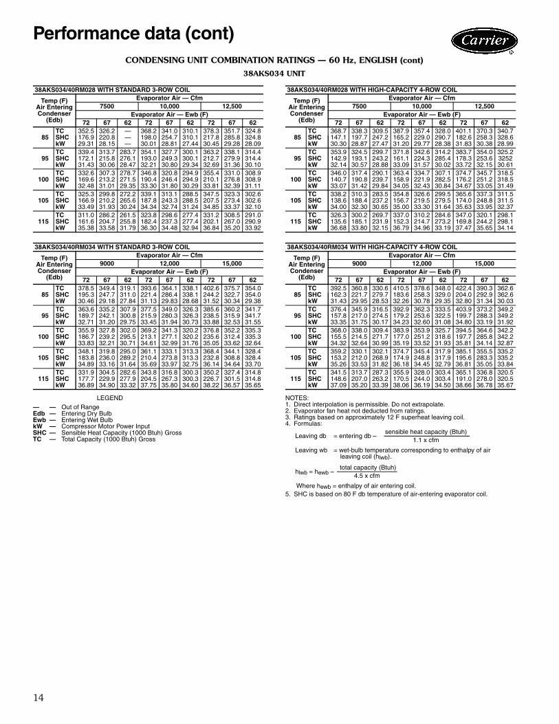
CONDENSING UNIT COMBINATION RATINGS — 60 Hz, ENGLISH (cont)
38AKS034 UNIT
LEGEND NOTES:1. Direct interpolation is permissible. Do not extrapolate. 2. Evaporator fan heat not deducted from ratings.3. Ratings based on approximately 12 F superheat leaving coil.4. Formulas:
Where hewb = enthalpy of air entering coil.5. SHC is based on 80 F db temperature of air-entering evaporator coil.
38AKS034/40RM028 WITH STANDARD 3-ROW COIL
Temp (F)Air EnteringCondenser
(Edb)
Evaporator Air — Cfm7500 10,000 12,500
Evaporator Air — Ewb (F)72 67 62 72 67 62 72 67 62
85TC 352.5 326.2 — 368.2 341.0 310.1 378.3 351.7 324.8SHC 176.9 220.8 — 198.0 254.7 310.1 217.8 285.8 324.8kW 29.31 28.15 — 30.01 28.81 27.44 30.45 29.28 28.09
95TC 339.4 313.7 283.7 354.1 327.7 300.1 363.2 338.1 314.4SHC 172.1 215.8 276.1 193.0 249.3 300.1 212.7 279.9 314.4kW 31.43 30.06 28.47 32.21 30.80 29.34 32.69 31.36 30.10
100TC 332.6 307.3 278.7 346.8 320.8 294.9 355.4 331.0 308.9SHC 169.6 213.2 271.5 190.4 246.4 294.9 210.1 276.8 308.9kW 32.48 31.01 29.35 33.30 31.80 30.29 33.81 32.39 31.11
105TC 325.3 299.8 272.2 339.1 313.1 288.5 347.5 323.3 302.6SHC 166.9 210.2 265.6 187.8 243.3 288.5 207.5 273.4 302.6kW 33.49 31.93 30.24 34.34 32.74 31.24 34.85 33.37 32.10
115TC 311.0 286.2 261.5 323.8 298.6 277.4 331.2 308.5 291.0SHC 161.6 204.7 255.8 182.4 237.3 277.4 202.1 267.0 290.9kW 35.38 33.58 31.79 36.30 34.48 32.94 36.84 35.20 33.92
38AKS034/40RM034 WITH STANDARD 3-ROW COIL
Temp (F)Air EnteringCondenser
(Edb)
Evaporator Air — Cfm9000 12,000 15,000
Evaporator Air — Ewb (F)72 67 62 72 67 62 72 67 62
85TC 378.5 349.4 319.1 393.6 364.1 338.1 402.6 375.7 354.0SHC 195.3 247.7 311.0 221.4 286.4 338.1 244.2 322.7 354.0kW 30.46 29.18 27.84 31.13 29.83 28.68 31.52 30.34 29.38
95TC 363.6 335.2 307.9 377.5 349.0 326.3 385.6 360.2 341.7SHC 189.7 242.1 300.8 215.9 280.3 326.3 238.5 315.9 341.7kW 32.71 31.20 29.75 33.45 31.94 30.73 33.88 32.53 31.55
100TC 355.9 327.8 302.0 369.2 341.3 320.2 376.8 352.2 335.3SHC 186.7 239.2 295.5 213.1 277.1 320.2 235.6 312.4 335.3kW 33.83 32.21 30.71 34.61 32.99 31.76 35.05 33.62 32.64
105TC 348.1 319.8 295.0 361.1 333.1 313.3 368.4 344.1 328.4SHC 183.8 236.0 289.2 210.4 273.8 313.3 232.8 308.8 328.4kW 34.89 33.16 31.64 35.69 33.97 32.75 36.14 34.64 33.70
115TC 331.9 304.5 282.6 343.8 316.8 300.3 350.2 327.4 314.8SHC 177.7 229.9 277.9 204.5 267.3 300.3 226.7 301.5 314.8kW 36.89 34.90 33.32 37.75 35.80 34.60 38.22 36.57 35.65
— — Out of RangeEdb — Entering Dry BulbEwb — Entering Wet BulbkW — Compressor Motor Power InputSHC — Sensible Heat Capacity (1000 Btuh) GrossTC — Total Capacity (1000 Btuh) Gross
38AKS034/40RM028 WITH HIGH-CAPACITY 4-ROW COIL
Temp (F)Air EnteringCondenser
(Edb)
Evaporator Air — Cfm7500 10,000 12,500
Evaporator Air — Ewb (F)72 67 62 72 67 62 72 67 62
85TC 368.7 338.3 309.5 387.9 357.4 328.0 401.1 370.3 340.7SHC 147.1 197.7 247.2 165.2 229.0 290.7 182.6 258.3 328.6kW 30.30 28.87 27.47 31.20 29.77 28.38 31.83 30.38 28.99
95TC 353.9 324.5 299.7 371.8 342.6 314.2 383.7 354.0 325.2SHC 142.9 193.1 243.2 161.1 224.3 285.4 178.3 253.6 3252kW 32.14 30.57 28.88 33.09 31.57 30.02 33.72 32.15 30.61
100TC 346.0 317.4 290.1 363.4 334.7 307.1 374.7 345.7 318.5SHC 140.7 190.8 239.7 158.9 221.9 282.5 176.2 251.2 318.5kW 33.07 31.42 29.84 34.05 32.43 30.84 34.67 33.05 31.49
105TC 338.2 310.3 283.5 354.8 326.6 299.5 365.6 337.3 311.5SHC 138.6 188.4 237.2 156.7 219.5 279.5 174.0 248.8 311.5kW 34.00 32.30 30.65 35.00 33.30 31.64 35.63 33.95 32.37
115TC 326.3 300.2 269.7 337.0 310.2 284.6 347.0 320.1 298.1SHC 135.6 185.1 231.9 152.3 214.7 273.2 169.8 244.2 298.1kW 36.68 33.80 32.15 36.79 34.96 33.19 37.47 35.65 34.14
38AKS034/40RM034 WITH HIGH-CAPACITY 4-ROW COIL
Temp (F)Air EnteringCondenser
(Edb)
Evaporator Air — Cfm9000 12,000 15,000
Evaporator Air — Ewb (F)72 67 62 72 67 62 72 67 62
85TC 392.5 360.8 330.6 410.5 378.6 348.0 422.4 390.3 362.6SHC 162.3 221.7 279.7 183.6 258.3 329.0 204.0 292.9 362.6kW 31.43 29.95 28.53 32.26 30.78 29.35 32.80 31.34 30.03
95TC 376.4 345.9 316.5 392.9 362.3 333.5 403.9 373.2 349.2SHC 157.8 217.0 274.5 179.2 253.6 322.5 199.7 288.3 349.2kW 33.35 31.75 30.17 34.23 32.60 31.08 34.80 33.19 31.92
100TC 368.0 338.0 309.4 383.9 353.9 325.7 394.5 364.6 342.2SHC 155.5 214.5 271.7 177.0 251.2 318.6 197.7 285.8 342.2kW 34.32 32.64 30.99 35.19 33.52 31.93 35.81 34.14 32.87
105TC 359.2 330.1 302.1 374.7 345.4 317.9 385.1 355.5 335.2SHC 153.2 212.0 268.9 174.9 248.8 317.9 195.6 283.3 335.2kW 35.26 33.53 31.82 36.18 34.45 32.79 36.81 35.05 33.84
115TC 341.5 313.7 287.3 355.9 328.0 303.4 365.1 336.8 320.5SHC 148.6 207.0 263.2 170.5 244.0 303.4 191.0 278.0 320.5kW 37.09 35.20 33.39 38.06 36.19 34.50 38.66 36.78 35.67
Leaving db = entering db –sensible heat capacity (Btuh)
1.1 x cfm
Leaving wb = wet-bulb temperature corresponding to enthalpy of airleaving coil (hlwb).
hlwb = hewb –total capacity (Btuh)
4.5 x cfm
Performance data (cont)

15
38AKS CONDENSING UNIT RATINGS — 50 Hz, ENGLISH
LEGEND
38AKS028
SST(F)
Air Temperature Entering Condenser (F)85 95 100 105 115 120 125
20TC 181.0 167.0 161.0 154.0 141.0 134.0 128.0kW 17.4 18.3 18.6 19.0 19.6 19.8 20.0SDT 108.0 117.0 122.0 126.0 136.0 141.0 145.0
25TC 202.0 187.0 180.0 173.0 159.0 152.0 145.0kW 18.5 19.4 19.8 20.2 20.9 21.2 21.5SDT 110.0 119.0 124.0 128.0 137.0 142.0 146.0
30TC 225.0 209.0 201.0 193.0 178.0 171.0 163.0kW 19.5 20.6 21.0 21.5 22.3 22.7 23.0SDT 112.0 121.0 126.0 130.0 139.0 143.0 148.0
35TC 249.0 231.0 223.0 215.0 198.0 190.0 182.0kW 20.6 21.7 22.3 22.8 23.7 24.2 24.6SDT 115.0 123.0 128.0 132.0 141.0 145.0 150.0
40TC 274.0 256.0 246.0 237.0 220.0 211.0 202.0kW 21.6 23.0 23.6 24.1 25.2 25.7 26.2SDT 117.0 126.0 130.0 135.0 143.0 148.0 152.0
45TC 301.0 281.0 271.0 261.0 242.0 233.0 224.0kW 22.8 24.2 24.9 25.5 26.7 27.3 27.8SDT 120.0 129.0 133.0 137.0 146.0 150.0 154.0
50TC 329.0 307.0 297.0 287.0 266.0 256.0 246.0kW 23.9 25.5 26.2 26.9 28.3 28.9 29.5SDT 123.0 131.0 136.0 140.0 148.0 152.0 157.0
38AKS034
SST(F)
Air Temperature Entering Condenser (F)85 95 100 105 115 120 125
20TC 203.0 187.0 178.0 170.0 153.0 145.0 136.0kW 20.0 20.8 21.1 21.4 21.8 21.8 21.8SDT 110.0 120.0 125.0 130.0 140.0 145.0 150.0
25TC 230.0 212.0 204.0 195.0 176.0 167.0 158.0kW 21.0 22.0 22.4 22.8 23.4 23.6 23.7SDT 110.0 120.0 125.0 130.0 140.0 145.0 150.0
30TC 256.0 239.0 230.0 221.0 202.0 192.0 182.0kW 22.0 23.2 23.7 24.1 24.9 25.3 25.5SDT 112.0 121.0 126.0 130.0 140.0 145.0 150.0
35TC 283.0 265.0 256.0 247.0 228.0 218.0 208.0kW 23.1 24.4 25.0 25.5 26.5 26.9 27.2SDT 114.0 123.0 127.0 132.0 141.0 146.0 150.0
40TC 311.0 292.0 282.0 273.0 253.0 243.0 233.0kW 24.3 25.7 26.4 27.0 28.1 28.6 29.0SDT 117.0 125.0 130.0 134.0 143.0 147.0 152.0
45TC 340.0 320.0 310.0 300.0 279.0 269.0 259.0kW 25.4 27.0 27.8 28.5 29.7 30.3 30.8SDT 119.0 128.0 132.0 136.0 145.0 149.0 154.0
50TC 371.0 350.0 339.0 328.0 307.0 296.0 285.0kW 26.6 28.4 29.2 30.0 31.4 32.1 32.7SDT 122.0 130.0 135.0 139.0 148.0 152.0 156.0
— — Out of RangekW — Compressor PowerSDT — Saturated Discharge Temperature at Compressor (F)SST — Saturated Suction Temperature (F)TC — Gross Cooling Capacity (1000 Btuh)
38AKS044
SST(F)
Air Temperature Entering Condenser (F)85 95 100 105 115 120 125
20TC 271.0 252.0 243.0 234.0 216.0 208.0 199.0kW 27.3 28.5 29.0 29.5 30.3 30.7 31.0SDT 109.0 119.0 124.0 129.0 139.0 144.0 149.0
25TC 305.0 284.0 274.0 264.0 245.0 235.0 225.0kW 28.6 30.0 30.7 31.3 32.3 32.8 33.2SDT 109.0 119.0 124.0 129.0 139.0 144.0 149.0
30TC 341.0 319.0 308.0 297.0 275.0 265.0 254.0kW 29.9 31.5 32.3 33.0 34.2 34.8 35.3SDT 109.0 119.0 124.0 129.0 139.0 144.0 149.0
35TC 377.0 355.0 343.0 332.0 309.0 297.0 286.0kW 31.3 33.1 33.9 34.7 36.1 36.8 37.4SDT 111.0 120.0 125.0 129.0 139.0 144.0 149.0
40TC 415.0 391.0 379.0 367.0 343.0 331.0 319.0kW 32.9 34.8 35.7 36.6 38.2 38.9 39.6SDT 113.0 122.0 126.0 131.0 140.0 145.0 150.0
45TC 455.0 429.0 416.0 403.0 377.0 365.0 352.0kW 34.5 36.6 37.6 38.6 40.3 41.1 41.9SDT 115.0 124.0 128.0 133.0 142.0 147.0 151.0
50TC 497.0 468.0 455.0 441.0 413.0 400.0 386.0kW 36.1 38.4 39.5 40.6 42.5 43.5 44.3SDT 117.0 126.0 131.0 135.0 144.0 149.0 153.0
16
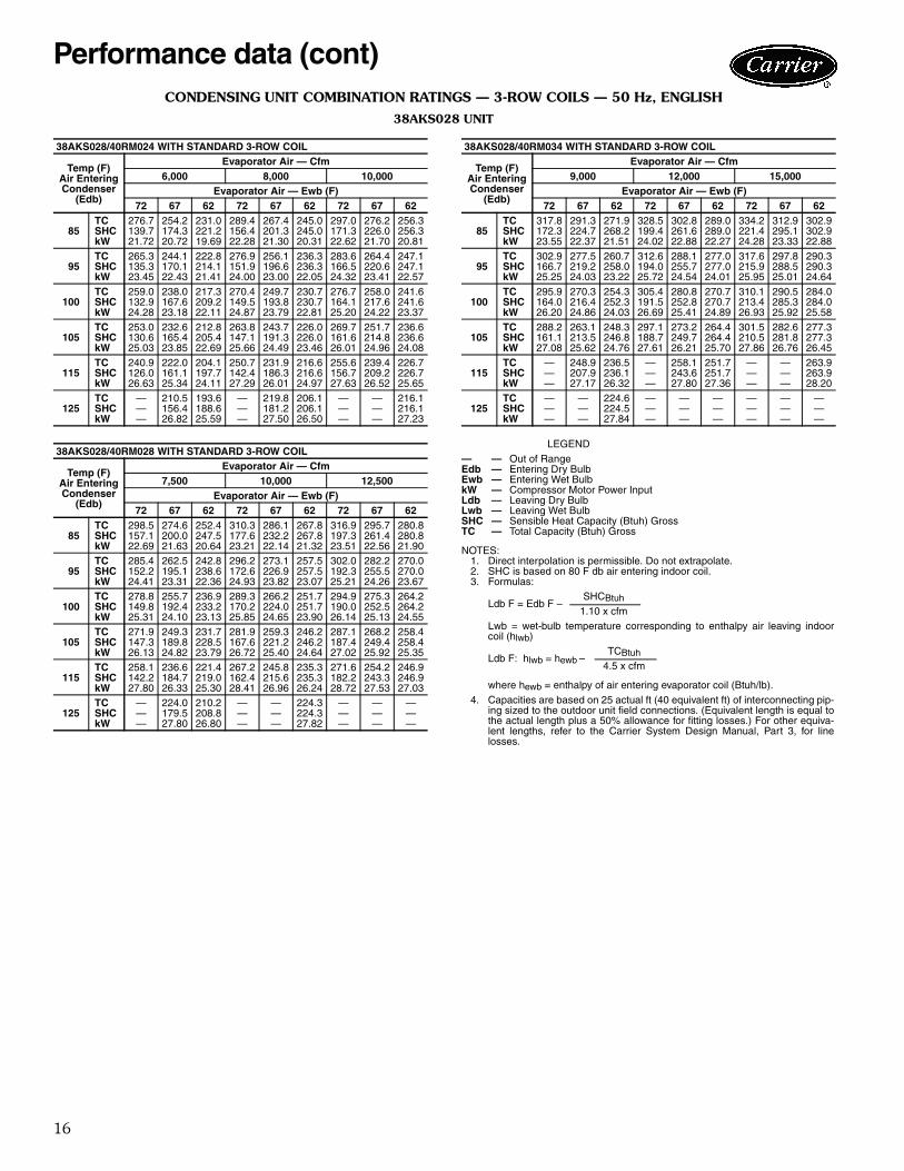
CONDENSING UNIT COMBINATION RATINGS — 3-ROW COILS — 50 Hz, ENGLISH
38AKS028 UNIT
LEGEND
NOTES:1. Direct interpolation is permissible. Do not extrapolate.2. SHC is based on 80 F db air entering indoor coil.3. Formulas:
Lwb = wet-bulb temperature corresponding to enthalpy air leaving indoorcoil (hlwb)
where hewb = enthalpy of air entering evaporator coil (Btuh/lb).4. Capacities are based on 25 actual ft (40 equivalent ft) of interconnecting pip-
ing sized to the outdoor unit field connections. (Equivalent length is equal tothe actual length plus a 50% allowance for fitting losses.) For other equiva-lent lengths, refer to the Carrier System Design Manual, Part 3, for linelosses.
38AKS028/40RM024 WITH STANDARD 3-ROW COIL
Temp (F)Air EnteringCondenser
(Edb)
Evaporator Air — Cfm6,000 8,000 10,000
Evaporator Air — Ewb (F)72 67 62 72 67 62 72 67 62
85TC 276.7 254.2 231.0 289.4 267.4 245.0 297.0 276.2 256.3SHC 139.7 174.3 221.2 156.4 201.3 245.0 171.3 226.0 256.3kW 21.72 20.72 19.69 22.28 21.30 20.31 22.62 21.70 20.81
95TC 265.3 244.1 222.8 276.9 256.1 236.3 283.6 264.4 247.1SHC 135.3 170.1 214.1 151.9 196.6 236.3 166.5 220.6 247.1kW 23.45 22.43 21.41 24.00 23.00 22.05 24.32 23.41 22.57
100TC 259.0 238.0 217.3 270.4 249.7 230.7 276.7 258.0 241.6SHC 132.9 167.6 209.2 149.5 193.8 230.7 164.1 217.6 241.6kW 24.28 23.18 22.11 24.87 23.79 22.81 25.20 24.22 23.37
105TC 253.0 232.6 212.8 263.8 243.7 226.0 269.7 251.7 236.6SHC 130.6 165.4 205.4 147.1 191.3 226.0 161.6 214.8 236.6kW 25.03 23.85 22.69 25.66 24.49 23.46 26.01 24.96 24.08
115TC 240.9 222.0 204.1 250.7 231.9 216.6 255.6 239.4 226.7SHC 126.0 161.1 197.7 142.4 186.3 216.6 156.7 209.2 226.7kW 26.63 25.34 24.11 27.29 26.01 24.97 27.63 26.52 25.65
125TC — 210.5 193.6 — 219.8 206.1 — — 216.1SHC — 156.4 188.6 — 181.2 206.1 — — 216.1kW — 26.82 25.59 — 27.50 26.50 — — 27.23
38AKS028/40RM028 WITH STANDARD 3-ROW COIL
Temp (F)Air EnteringCondenser
(Edb)
Evaporator Air — Cfm7,500 10,000 12,500
Evaporator Air — Ewb (F)72 67 62 72 67 62 72 67 62
85TC 298.5 274.6 252.4 310.3 286.1 267.8 316.9 295.7 280.8SHC 157.1 200.0 247.5 177.6 232.2 267.8 197.3 261.4 280.8kW 22.69 21.63 20.64 23.21 22.14 21.32 23.51 22.56 21.90
95TC 285.4 262.5 242.8 296.2 273.1 257.5 302.0 282.2 270.0SHC 152.2 195.1 238.6 172.6 226.9 257.5 192.3 255.5 270.0kW 24.41 23.31 22.36 24.93 23.82 23.07 25.21 24.26 23.67
100TC 278.8 255.7 236.9 289.3 266.2 251.7 294.9 275.3 264.2SHC 149.8 192.4 233.2 170.2 224.0 251.7 190.0 252.5 264.2kW 25.31 24.10 23.13 25.85 24.65 23.90 26.14 25.13 24.55
105TC 271.9 249.3 231.7 281.9 259.3 246.2 287.1 268.2 258.4SHC 147.3 189.8 228.5 167.6 221.2 246.2 187.4 249.4 258.4kW 26.13 24.82 23.79 26.72 25.40 24.64 27.02 25.92 25.35
115TC 258.1 236.6 221.4 267.2 245.8 235.3 271.6 254.2 246.9SHC 142.2 184.7 219.0 162.4 215.6 235.3 182.2 243.3 246.9kW 27.80 26.33 25.30 28.41 26.96 26.24 28.72 27.53 27.03
125TC — 224.0 210.2 — — 224.3 — — —SHC — 179.5 208.8 — — 224.3 — — —kW — 27.80 26.80 — — 27.82 — — —
38AKS028/40RM034 WITH STANDARD 3-ROW COIL
Temp (F)Air EnteringCondenser
(Edb)
Evaporator Air — Cfm9,000 12,000 15,000
Evaporator Air — Ewb (F)72 67 62 72 67 62 72 67 62
85TC 317.8 291.3 271.9 328.5 302.8 289.0 334.2 312.9 302.9SHC 172.3 224.7 268.2 199.4 261.6 289.0 221.4 295.1 302.9kW 23.55 22.37 21.51 24.02 22.88 22.27 24.28 23.33 22.88
95TC 302.9 277.5 260.7 312.6 288.1 277.0 317.6 297.8 290.3SHC 166.7 219.2 258.0 194.0 255.7 277.0 215.9 288.5 290.3kW 25.25 24.03 23.22 25.72 24.54 24.01 25.95 25.01 24.64
100TC 295.9 270.3 254.3 305.4 280.8 270.7 310.1 290.5 284.0SHC 164.0 216.4 252.3 191.5 252.8 270.7 213.4 285.3 284.0kW 26.20 24.86 24.03 26.69 25.41 24.89 26.93 25.92 25.58
105TC 288.2 263.1 248.3 297.1 273.2 264.4 301.5 282.6 277.3SHC 161.1 213.5 246.8 188.7 249.7 264.4 210.5 281.8 277.3kW 27.08 25.62 24.76 27.61 26.21 25.70 27.86 26.76 26.45
115TC — 248.9 236.5 — 258.1 251.7 — — 263.9SHC — 207.9 236.1 — 243.6 251.7 — — 263.9kW — 27.17 26.32 — 27.80 27.36 — — 28.20
125TC — — 224.6 — — — — — —SHC — — 224.5 — — — — — —kW — — 27.84 — — — — — —
— — Out of RangeEdb — Entering Dry BulbEwb — Entering Wet BulbkW — Compressor Motor Power InputLdb — Leaving Dry BulbLwb — Leaving Wet BulbSHC — Sensible Heat Capacity (Btuh) GrossTC — Total Capacity (Btuh) Gross
Ldb F = Edb F –SHCBtuh
1.10 x cfm
Ldb F: hlwb = hewb –TCBtuh
4.5 x cfm
Performance data (cont)
17
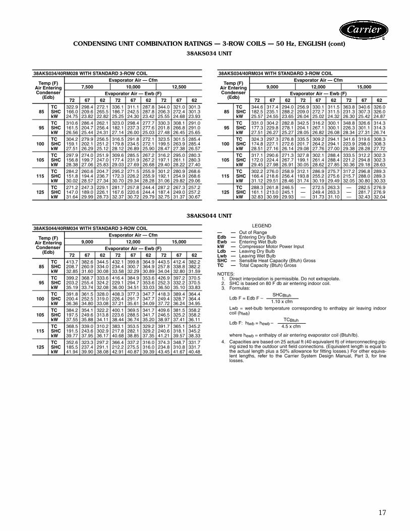
CONDENSING UNIT COMBINATION RATINGS — 3-ROW COILS — 50 Hz, ENGLISH (cont)
38AKS034 UNIT
38AKS044 UNIT
LEGEND
NOTES:1. Direct interpolation is permissible. Do not extrapolate.2. SHC is based on 80 F db air entering indoor coil.3. Formulas:
Lwb = wet-bulb temperature corresponding to enthalpy air leaving indoorcoil (hlwb)
where hewb = enthalpy of air entering evaporator coil (Btuh/lb).4. Capacities are based on 25 actual ft (40 equivalent ft) of interconnecting pip-
ing sized to the outdoor unit field connections. (Equivalent length is equal tothe actual length plus a 50% allowance for fitting losses.) For other equiva-lent lengths, refer to the Carrier System Design Manual, Part 3, for linelosses.
38AKS034/40RM028 WITH STANDARD 3-ROW COIL
Temp (F)Air EnteringCondenser
(Edb)
Evaporator Air — Cfm7,500 10,000 12,500
Evaporator Air — Ewb (F)72 67 62 72 67 62 72 67 62
85TC 322.9 298.4 272.1 336.1 311.1 287.8 344.0 321.0 301.3SHC 166.0 209.6 265.5 186.7 242.5 287.8 206.3 272.4 301.3kW 24.75 23.82 22.82 25.25 24.30 23.42 25.55 24.68 23.93
95TC 310.6 286.4 262.1 323.0 298.4 277.7 330.3 308.1 291.0SHC 161.5 204.7 256.4 182.1 237.3 277.6 201.8 266.8 291.0kW 26.56 25.44 24.31 27.14 26.00 25.03 27.48 26.45 25.65
100TC 304.2 279.9 256.5 316.5 291.8 272.1 323.5 301.5 285.4SHC 159.1 202.1 251.2 179.8 234.5 272.1 199.5 263.9 285.4kW 27.51 26.29 25.12 28.12 26.89 25.90 28.47 27.38 26.57
105TC 297.9 274.0 251.9 309.6 285.5 267.2 316.2 295.0 280.3SHC 156.8 199.7 247.0 177.4 231.9 267.2 197.1 261.1 280.3kW 28.38 27.06 25.83 29.03 27.69 26.68 29.40 28.22 27.40
115TC 284.2 260.6 204.7 295.2 271.5 255.9 301.2 280.9 268.6SHC 151.8 194.4 236.7 172.3 226.2 255.9 192.1 254.9 268.6kW 30.02 28.57 27.34 30.70 29.34 28.28 31.06 29.82 29.06
125TC 271.2 247.3 229.1 281.7 257.8 244.4 287.2 267.3 257.2SHC 147.0 189.0 226.1 167.6 220.6 244.4 187.4 249.0 257.2kW 31.64 29.99 28.73 32.37 30.72 29.79 32.75 31.37 30.67
38AKS034/40RM034 WITH STANDARD 3-ROW COIL
Temp (F)Air EnteringCondenser
(Edb)
Evaporator Air — Cfm9,000 12,000 15,000
Evaporator Air — Ewb (F)72 67 62 72 67 62 72 67 62
85TC 344.6 317.4 294.0 256.9 330.1 311.5 363.8 340.6 326.0SHC 182.5 235.1 288.2 209.0 272.7 311.5 231.3 307.3 326.0kW 25.57 24.55 23.65 26.04 25.02 24.32 26.30 25.42 24.87
95TC 331.0 304.2 282.8 342.5 316.2 300.1 348.8 326.6 314.3SHC 177.3 229.8 278.1 204.1 267.1 300.1 226.3 301.1 314.3kW 27.51 26.27 25.27 28.05 26.82 26.08 28.34 27.31 26.74
100TC 324.3 297.3 276.8 335.5 309.2 294.1 341.6 319.6 308.3SHC 174.8 227.1 272.6 201.7 264.2 294.1 223.9 298.0 308.3kW 28.51 27.16 26.14 29.08 27.76 27.00 29.38 28.28 27.72
105TC 317.1 290.6 271.3 327.8 302.1 288.4 333.5 312.2 302.3SHC 172.0 224.4 267.7 199.1 261.4 288.4 221.2 294.8 302.3kW 29.45 27.98 26.91 30.05 28.62 27.85 30.36 29.18 28.63
115TC 302.2 276.0 258.9 312.1 286.9 275.7 317.2 296.8 289.3SHC 166.4 218.6 256.4 193.8 255.2 275.6 215.7 288.0 289.3kW 31.12 29.51 28.46 31.74 30.19 29.49 32.05 30.80 30.33
125TC 288.3 261.8 246.5 — 272.5 263.3 — 282.5 276.9SHC 161.1 213.0 245.1 — 249.4 263.3 — 281.7 276.9kW 32.83 30.99 29.93 — 31.73 31.10 — 32.43 32.04
38AKS044/40RM034 WITH STANDARD 3-ROW COIL
Temp (F)Air EnteringCondenser
(Edb)
Evaporator Air — Cfm9,000 12,000 15,000
Evaporator Air — Ewb (F)72 67 62 72 67 62 72 67 62
85TC 413.7 382.6 344.5 432.1 399.8 364.9 443.5 412.4 382.2SHC 208.7 260.9 334.0 234.4 300.7 364.9 257.8 338.8 382.2kW 32.85 31.60 30.08 33.58 32.29 30.89 34.04 32.80 31.59
95TC 399.2 368.7 333.6 416.4 384.9 353.6 426.9 397.2 370.5SHC 203.2 255.4 324.2 229.1 294.7 353.6 252.3 332.2 370.5kW 35.19 33.74 32.08 36.00 34.51 33.03 36.50 35.10 33.83
100TC 391.8 361.5 328.0 408.3 377.3 347.7 418.3 389.4 364.4SHC 200.4 252.5 319.0 226.4 291.7 347.7 249.4 328.7 364.4kW 36.36 34.80 33.08 37.21 35.61 34.09 37.72 36.24 34.95
105TC 384.2 354.1 322.2 400.1 369.5 341.7 409.6 381.5 358.2SHC 197.5 249.6 313.8 223.6 288.5 341.7 246.5 325.2 358.2kW 37.55 35.88 34.11 38.44 36.74 35.20 38.97 37.41 36.11
115TC 368.5 339.0 310.2 383.1 353.5 329.2 391.7 365.1 345.2SHC 191.5 243.6 302.9 217.8 282.1 329.2 240.6 318.1 345.2kW 39.77 37.95 36.17 40.68 38.85 37.35 41.21 39.57 38.33
125TC 352.6 323.3 297.2 366.4 337.2 316.0 374.3 348.7 331.7SHC 185.5 237.4 291.1 212.2 275.5 316.0 234.8 310.8 331.7kW 41.94 39.90 38.08 42.91 40.87 39.39 43.45 41.67 40.48
— — Out of RangeEdb — Entering Dry BulbEwb — Entering Wet BulbkW — Compressor Motor Power InputLdb — Leaving Dry BulbLwb — Leaving Wet BulbSHC — Sensible Heat Capacity (Btuh) GrossTC — Total Capacity (Btuh) Gross
Ldb F = Edb F –SHCBtuh
1.10 x cfm
Ldb F: hlwb = hewb –TCBtuh
4.5 x cfm

18
CONDENSING UNIT COMBINATION RATINGS — 4-ROW HIGH-CAPACITY COILS — 50 Hz, ENGLISH
38AKS028 UNIT — HIGH CAPACITY
LEGEND
1. Direct interpolation is permissible. Do not extrapolate.2. SHC is based on 80 F db air entering indoor coil.3. Formulas:
Lwb = wet-bulb temperature corresponding to enthalpy air leaving indoorcoil (hlwb)
where hewb = enthalpy of air entering evaporator coil (Btuh/lb).4. Capacities are based on 25 actual ft (40 equivalent ft) of interconnecting pip-
ing sized to the outdoor unit field connections. (Equivalent length is equal tothe actual length plus a 50% allowance for fitting losses.) For other equiva-lent lengths, refer to the Carrier System Design Manual, Part 3, for linelosses.
38AKS028/40RM024 WITH 4-ROW HIGH-CAPACITY COILS
Temp (F)Air EnteringCondenser
(Edb)
Evaporator Air — Cfm6,000 8,000 10,000
Evaporator Air — Ewb (F)62 67 72 62 67 72 62 67 72
85TC 257.4 282.2 308.4 274.1 299.2 325.8 284.9 310.4 337.3SHC 205.5 164.8 123.1 243.4 191.9 138.8 275.4 217.4 153.8kW 21.83 22.91 24.02 22.58 23.64 24.76 23.05 24.14 25.26
95TC 245.9 269.7 295.2 261.5 285.8 311.3 272.0 295.7 321.5SHC 201.1 160.7 119.4 238.5 188.0 135.0 272.0 213.4 150.2kW 23.31 24.51 25.75 24.13 25.32 26.55 24.63 25.80 27.05
100TC 240.1 263.5 288.4 254.7 278.9 303.9 265.3 288.3 313.7SHC 198.8 158.6 117.4 235.6 185.9 133.2 265.3 211.4 148.3kW 24.04 25.28 26.58 24.85 26.12 27.40 25.39 26.60 27.92
105TC 234.4 257.2 281.4 248.5 271.8 296.3 260.1 280.8 305.5SHC 196.7 156.6 115.5 233.7 183.9 131.2 260.1 209.2 146.4kW 24.80 26.11 27.46 25.62 26.96 28.31 26.27 27.46 28.81
115TC 222.7 244.6 267.5 235.9 257.4 280.9 248.8 265.9 289.4SHC 192.3 152.5 111.5 228.2 179.7 127.5 248.8 204.9 142.6kW 26.26 27.68 29.15 27.11 28.52 29.99 27.95 29.06 30.52
38AKS028/40RM028 WITH 4-ROW HIGH-CAPACITY COILS
Temp (F)Air EnteringCondenser
(Edb)
Evaporator Air — Cfm7,500 10,000 12,500
Evaporator Air — Ewb (F)62 67 72 62 67 72 62 67 72
85TC 263.5 287.8 313.2 277.6 301.7 327.2 290.9 310.7 336.6SHC 229.3 181.2 131.6 269.1 212.1 149.7 290.9 241.2 167.2kW 22.01 23.07 24.15 22.65 23.67 24.75 23.20 24.06 25.15
95TC 251.6 274.7 299.0 264.8 287.7 312.1 279.3 295.6 320.4SHC 224.7 177.1 127.8 264.8 208.0 146.1 279.3 236.9 163.5kW 23.52 24.68 25.87 24.18 25.34 26.51 24.90 25.71 26.92
100TC 245.7 268.3 292.0 258.5 280.4 304.7 273.5 288.1 312.3SHC 222.5 175.1 126.0 258.5 206.1 144.4 273.5 234.7 161.7kW 24.25 25.47 26.71 24.94 26.12 27.39 25.75 26.52 27.77
105TC 239.6 261.6 284.7 253.0 273.0 296.6 267.5 280.4 304.1SHC 220.0 173.1 124.1 253.0 204.1 142.6 267.5 232.5 159.7kW 25.01 26.27 27.57 25.76 26.93 28.24 26.61 27.34 28.65
115TC 227.1 248.2 270.3 241.9 258.4 280.7 255.1 265.3 287.7SHC 215.1 169.0 120.5 241.9 199.8 138.9 255.1 228.1 156.2kW 26.45 27.84 29.26 27.41 28.49 29.92 28.27 28.94 30.35
38AKS028/40RM034 WITH 4-ROW HIGH-CAPACITY COILS
Temp (F)Air EnteringCondenser
(Edb)
Evaporator Air — Cfm9,000 12,000 15,000
Evaporator Air — Ewb (F)62 67 72 62 67 72 62 67 72
85TC 279.7 305.5 332.1 296.4 318.0 345.0 312.8 326.3 353.3SHC 259.7 204.9 146.4 296.4 241.8 168.3 312.8 275.6 189.0kW 22.84 23.92 25.03 23.51 24.46 25.57 24.21 24.82 25.92
95TC 267.2 291.2 317.0 284.9 302.8 328.6 299.8 310.6 336.3SHC 255.4 200.8 142.6 284.9 237.5 164.4 299.8 271.3 185.4kW 24.40 25.59 26.84 25.26 26.15 27.39 25.98 26.54 27.76
100TC 260.4 284.0 309.4 278.9 295.1 320.4 293.4 302.8 327.9SHC 252.0 198.9 140.9 278.9 235.3 162.6 293.4 268.8 183.6kW 25.14 26.38 27.70 26.10 26.97 28.27 26.84 27.38 28.66
105TC 253.7 276.7 301.3 272.8 287.5 312.1 286.8 294.6 319.3SHC 248.4 196.7 139.0 272.8 233.2 160.9 286.8 266.0 181.8kW 25.92 27.22 28.58 26.99 27.83 29.18 27.77 28.24 29.59
115TC 241.1 262.0 285.5 260.3 272.1 295.5 273.6 278.4 301.9SHC 241.1 192.4 135.2 260.3 228.8 157.2 273.6 260.8 177.9kW 27.44 28.82 30.28 28.68 29.46 30.91 29.54 29.85 31.32
— — Out of RangeEdb — Entering Dry BulbEwb — Entering Wet BulbkW — Compressor Motor Power InputLdb — Leaving Dry BulbLwb — Leaving Wet BulbSHC — Sensible Heat Capacity (Btuh) GrossTC — Total Capacity (Btuh) Gross
Ldb F = Edb F –SHCBtuh
1.10 x cfm
Ldb F: hlwb = hewb –TCBtuh
4.5 x cfm
Performance data (cont)
19
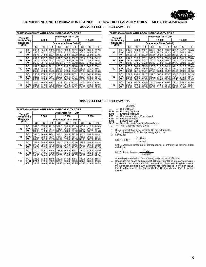
CONDENSING UNIT COMBINATION RATINGS — 4-ROW HIGH-CAPACITY COILS — 50 Hz, ENGLISH (cont)
38AKS034 UNIT — HIGH CAPACITY
38AKS044 UNIT — HIGH CAPACITY
LEGEND
1. Direct interpolation is permissible. Do not extrapolate.2. SHC is based on 80 F db air entering indoor coil.3. Formulas:
Lwb = wet-bulb temperature corresponding to enthalpy air leaving indoorcoil (hlwb)
where hewb = enthalpy of air entering evaporator coil (Btuh/lb).4. Capacities are based on 25 actual ft (40 equivalent ft) of interconnecting pip-
ing sized to the outdoor unit field connections. (Equivalent length is equal tothe actual length plus a 50% allowance for fitting losses.) For other equiva-lent lengths, refer to the Carrier System Design Manual, Part 3, for linelosses.
38AKS034/40RM028 WITH 4-ROW HIGH-CAPACITY COILS
Temp (F)Air EnteringCondenser
(Edb)
Evaporator Air — Cfm7,500 10,000 12,500
Evaporator Air — Ewb (F)62 67 72 62 67 72 62 67 72
85TC 280.1 305.6 332.5 294.8 320.8 347.7 307.1 331.0 357.9SHC 235.6 187.1 137.0 276.9 217.7 154.8 307.1 246.9 172.1kW 23.75 24.89 26.04 24.40 25.54 26.70 24.96 25.98 27.15
95TC 267.9 292.7 318.7 282.5 306.8 332.7 295.4 316.4 342.2SHC 230.9 182.8 133.3 271.9 213.6 151.0 295.4 242.9 168.4kW 25.19 26.45 27.75 25.93 27.17 28.43 26.59 27.65 28.90
100TC 261.8 286.0 311.1 276.0 299.7 325.0 289.5 308.7 334.2SHC 228.6 180.6 131.1 268.8 211.6 149.2 289.5 240.7 166.7kW 25.88 27.20 28.55 26.67 27.94 29.27 27.39 28.43 29.76
105TC 255.7 279.2 303.7 268.8 292.5 317.1 283.4 300.9 325.8SHC 226.3 178.5 129.1 268.8 209.5 147.4 283.4 238.5 164.8kW 26.61 27.98 29.38 27.39 28.74 30.13 28.22 29.23 30.63
115TC 243.0 265.3 288.7 256.2 277.4 301.1 271.0 285.0 308.7SHC 221.5 174.2 125.2 256.2 205.3 143.6 271.0 234.0 160.8kW 27.99 29.48 31.00 28.88 30.27 31.81 29.86 30.76 32.29
38AKS034/40RM034 WITH 4-ROW HIGH-CAPACITY COILS
Temp (F)Air EnteringCondenser
(Edb)
Evaporator Air — Cfm9,000 12,000 15,000
Evaporator Air — Ewb (F)62 67 72 62 67 72 62 67 72
85TC 297.9 324.3 352.1 312.9 338.8 366.7 330.1 347.7 375.8SHC 267.9 210.7 151.5 312.9 247.8 173.3 330.1 282.1 194.1kW 24.55 25.70 26.90 25.21 26.34 27.53 25.95 26.72 27.91
95TC 284.9 310.5 337.1 300.9 323.5 350.5 317.7 331.8 358.8SHC 262.5 206.5 147.7 300.9 243.5 169.7 317.7 277.4 190.2kW 26.07 27.35 28.66 26.87 27.99 29.32 27.72 28.39 29.73
100TC 278.3 303.5 329.5 295.0 315.7 342.2 311.0 323.8 350.3SHC 260.2 204.5 145.9 295.0 241.3 167.8 311.0 275.1 188.5kW 26.81 28.15 29.51 27.69 28.80 30.17 28.56 29.21 30.58
105TC 271.7 296.2 321.7 289.0 307.8 333.7 304.3 315.7 341.5SHC 257.6 202.4 143.9 289.0 239.1 165.8 304.3 272.9 186.6kW 27.57 28.97 30.40 28.55 29.63 31.06 29.42 30.06 31.49
115TC 257.9 280.9 305.5 276.5 291.8 316.4 290.6 299.1 323.6SHC 251.0 198.0 139.9 276.5 234.5 161.9 290.6 267.7 182.7kW 28.99 30.49 32.08 30.21 31.18 32.75 31.11 31.66 33.21
38AKS044/40RM034 WITH 4-ROW HIGH-CAPACITY COILS
Temp (F)Air EnteringCondenser
(Edb)
Evaporator Air — Cfm9,000 12,000 15,000
Evaporator Air — Ewb (F)62 67 72 62 67 72 62 67 72
85TC 347.6 378.8 411.3 367.0 398.3 431.0 380.2 410.6 443.5SHC 287.1 228.1 167.7 338.3 265.2 189.3 380.2 300.0 209.8kW 33.03 34.90 36.81 34.20 36.06 38.02 34.97 36.77 38.73
95TC 334.0 363.8 395.1 351.4 381.6 412.9 365.8 393.1 424.4SHC 282.2 223.4 163.4 331.7 260.3 184.7 365.8 295.2 205.3kW 34.80 36.76 38.83 35.94 37.95 40.03 36.90 38.70 40.79
100TC 327.2 356.3 386.8 344.0 373.1 403.6 359.2 384.3 414.8SHC 279.4 221.0 161.2 328.7 257.8 182.5 359.2 292.8 203.2kW 35.71 37.74 39.87 36.87 38.91 41.05 37.96 39.69 41.83
105TC 319.9 348.7 378.4 336.6 364.6 394.3 352.0 375.4 405.0SHC 276.5 218.5 159.0 325.2 255.4 180.2 352.0 290.3 201.0kW 36.56 38.69 40.89 37.78 39.85 42.05 38.93 40.65 42.84
115TC 305.3 332.4 360.5 320.5 347.2 375.3 337.6 357.2 385.3SHC 271.1 213.5 153.9 320.5 250.4 175.6 337.6 285.1 196.5kW 38.19 40.43 42.74 39.46 41.63 43.95 40.85 42.46 44.79
— — Out of RangeEdb — Entering Dry BulbEwb — Entering Wet BulbkW — Compressor Motor Power InputLdb — Leaving Dry BulbLwb — Leaving Wet BulbSHC — Sensible Heat Capacity (Btuh) GrossTC — Total Capacity (Btuh) Gross
Ldb F = Edb F –SHCBtuh
1.10 x cfm
Ldb F: hlwb = hewb –TCBtuh
4.5 x cfm

20
38AKS CONDENSING UNIT RATINGS — 50 Hz, SI
LEGEND
38AKS028
SST(C)
Air Temperature Entering Condenser (C)28 32 36 40 44 48 52
–6TC 55.3 52.4 49.5 46.6 43.8 41.0 38.3kW 17.4 18.0 18.6 19.1 19.6 20.0 20.4SDT 41.2 44.8 48.5 52.1 55.8 59.6 63.3
–4TC 60.4 57.3 54.2 51.1 48.1 45.2 42.3kW 18.2 18.9 19.5 20.1 20.6 21.1 21.5SDT 42.1 45.7 49.3 52.9 56.5 60.2 63.8
–2TC 64.4 61.1 57.8 54.7 51.5 48.5 45.4kW 18.8 19.5 20.3 20.9 21.5 22.0 22.4SDT 42.9 46.4 50.0 53.6 57.1 60.7 64.4
0TC 69.9 66.4 62.9 59.6 56.3 53.0 49.7kW 19.6 20.4 21.2 21.9 22.6 23.1 23.7SDT 43.9 47.4 50.9 54.5 58.0 61.6 65.1
2TC 75.6 71.9 68.3 64.7 61.2 57.7 54.3kW 20.5 21.3 22.2 23.0 23.7 24.3 24.9SDT 45.0 48.5 52.0 55.4 59.0 62.5 66.0
4TC 80.2 76.3 72.5 68.7 65.0 61.4 57.8kW 21.1 22.0 22.9 23.8 24.5 25.2 25.9SDT 45.9 49.3 52.8 56.2 59.7 63.2 66.7
6TC 86.4 82.3 78.3 74.3 70.3 66.5 62.7kW 22.0 23.0 23.9 24.8 25.7 26.5 27.2SDT 47.1 50.5 53.9 57.3 60.8 64.2 67.7
8TC 91.2 87.0 82.8 78.6 74.5 70.5 66.5kW 22.6 23.7 24.7 25.7 26.6 27.4 28.2SDT 48.0 51.4 54.8 58.2 61.6 65.0 68.4
10TC 97.9 93.5 89.0 84.6 80.3 76.0 71.7kW 23.5 24.6 25.7 26.8 27.8 28.7 29.5SDT 49.3 52.7 56.0 59.4 62.8 66.1 69.5
38AKS034
SST(C)
Air Temperature Entering Condenser (C)28 32 36 40 44 48 52
–6TC 62.4 58.9 55.3 51.7 48.1 44.5 40.8kW 20.0 20.6 21.2 21.6 21.9 22.2 22.2SDT 42.1 46.0 50.0 54.1 58.0 62.0 66.1
–4TC 68.7 65.0 61.3 57.6 53.7 49.9 46.1kW 20.7 21.4 22.2 22.7 23.2 23.5 23.7SDT 42.2 46.1 50.1 54.1 58.1 62.1 66.1
–2TC 73.3 69.7 66.0 62.1 58.2 54.3 50.3kW 21.3 22.1 22.9 23.5 24.1 24.5 24.8SDT 42.7 46.4 50.2 54.1 58.1 62.0 66.1
0TC 79.5 75.8 72.1 68.3 64.3 60.3 56.1kW 22.1 23.0 23.9 24.6 25.2 25.8 26.2SDT 43.6 47.2 50.8 54.5 58.3 62.1 66.1
2TC 85.9 82.1 78.2 74.3 70.3 66.3 62.1kW 23.0 24.0 24.9 25.7 26.4 27.1 27.6SDT 44.6 48.1 51.7 55.2 58.9 62.5 66.2
4TC 90.9 87.0 83.0 79.0 74.9 70.8 66.6kW 23.7 24.7 25.7 26.6 27.4 28.1 28.7SDT 45.4 48.9 52.5 56.0 59.5 63.1 66.6
6TC 97.8 93.6 89.5 85.3 81.0 76.8 72.4kW 24.6 25.7 26.8 27.8 28.6 29.4 30.1SDT 46.6 50.1 53.5 57.0 60.5 64.0 67.5
8TC 103.0 98.8 94.5 90.2 85.8 81.4 76.9kW 25.2 26.4 27.6 28.6 29.6 30.5 31.2SDT 47.5 50.9 54.4 57.8 61.3 64.7 68.2
10TC 110.0 106.0 101.0 96.9 92.3 87.7 83.0kW 26.2 27.4 28.7 29.8 30.9 31.9 32.7SDT 48.8 52.2 55.6 59.0 62.4 65.8 69.2
— — Out of RangekW — Compressor PowerSDT — Saturated Discharge Temperature at Compressor (C)SST — Saturated Suction Temperature (C)TC — Gross Cooling Capacity (kW)
38AKS044
SST(C)
Air Temperature Entering Condenser (C)28 32 36 40 44 48 52
–6TC 82.8 78.8 74.8 70.9 67.1 63.3 59.5kW 27.3 28.1 29.0 29.7 30.4 31.0 31.5SDT 41.4 45.3 49.3 53.3 57.3 61.3 65.3
–4TC 90.9 86.5 82.3 78.0 73.9 69.8 65.7kW 28.3 29.3 30.3 31.1 31.9 32.6 33.2SDT 41.3 45.3 49.3 53.3 57.3 61.3 65.3
–2TC 97.3 92.7 88.2 83.7 79.4 75.0 70.7kW 29.0 30.1 31.2 32.2 33.0 33.8 34.5SDT 41.4 45.3 49.3 53.3 57.3 61.3 65.3
0TC 106.0 101.0 96.5 91.7 87.1 82.4 77.8kW 30.0 31.2 32.4 33.5 34.5 35.4 36.2SDT 41.8 45.6 49.4 53.4 57.3 61.3 65.3
2TC 115.0 110.0 105.0 99.9 95.1 90.2 85.3kW 31.2 32.5 33.7 34.9 36.0 37.0 37.9SDT 42.5 46.2 50.0 53.7 57.5 61.4 65.4
4TC 121.0 116.0 111.0 106.0 101.0 96.1 91.1kW 32.1 33.5 34.8 36.0 37.2 38.2 39.2SDT 43.2 46.9 50.5 54.2 58.0 61.7 65.5
6TC 130.0 125.0 120.0 114.0 109.0 104.0 98.8kW 33.3 34.8 36.2 37.6 38.8 40.0 41.1SDT 44.2 47.8 51.5 55.1 58.7 62.4 66.1
8TC 138.0 132.0 127.0 121.0 116.0 110.0 105.0kW 34.2 35.8 37.3 38.8 40.1 41.3 42.5SDT 45.0 48.6 52.2 55.8 59.4 63.0 66.7
10TC 148.0 142.0 136.0 130.0 124.0 118.0 113.0kW 35.5 37.2 38.8 40.4 41.8 43.2 44.4SDT 46.1 49.7 53.2 56.8 60.4 64.0 67.6
Performance data (cont)

21
CONDENSING UNIT COMBINATION RATINGS — 3-ROW COILS — 50 Hz, SI
38AKS028 UNIT
LEGEND
NOTES:1. Direct interpolation is permissible. Do not extrapolate.2. SHC is based on 26.7 C db air entering indoor coil.3. Formulas:
Lwb = wet-bulb temperature corresponding to enthalpy air leaving indoorcoil (hlwb)
where hewb = enthalpy of air entering evaporator coil (kj/kg).4. Capacities are based on 7.6 actual m (12.2 equivalent m) of interconnecting
piping sized to the outdoor unit field connections. (Equivalent length is equalto the actual length plus a 50% allowance for fitting losses.) For other equiv-alent lengths, refer to the Carrier System Design Manual, Part 3, for linelosses.
38AKS028/40RM024 WITH STANDARD 3-ROW COIL
Temp (C)Air EnteringCondenser
(Edb)
Evaporator Air — L/s2900 3800 4700
Evaporator Air — Ewb (C)22 20 16 22 20 16 22 20 16
20TC 86.6 81.7 73.9 90.6 84.8 77.6 93.1 87.7 80.5SHC 44.0 51.5 73.9 48.9 59.2 77.6 53.4 65.8 80.5kW 19.70 19.31 18.70 20.01 19.55 18.99 20.20 19.78 19.22
28TC 81.9 77.1 70.0 85.6 80.0 73.6 87.8 82.7 76.4SHC 42.2 49.6 70.0 47.1 57.1 73.6 51.6 63.5 76.4kW 21.44 20.84 19.95 21.90 21.20 20.39 22.18 21.54 20.75
32TC 79.4 74.6 67.8 82.9 77.5 71.3 85.0 80.0 74.1SHC 41.2 48.6 67.8 46.1 55.9 71.3 50.6 62.2 74.1kW 22.57 21.85 20.84 23.09 22.28 21.36 23.41 22.66 21.78
36TC 77.0 72.2 65.8 80.2 74.9 69.2 82.2 77.4 71.9SHC 40.2 47.6 65.8 45.2 54.8 69.2 49.6 61.0 71.9kW 23.66 22.81 21.67 24.23 23.30 22.28 24.59 23.74 22.76
40TC 74.4 69.7 63.7 77.4 72.4 67.0 79.3 74.7 69.6SHC 39.2 46.6 63.7 44.2 53.6 67.0 48.6 59.8 69.6kW 24.82 23.84 22.58 25.45 24.39 23.27 25.84 24.87 23.82
44TC 71.8 67.1 61.4 74.6 69.7 64.6 76.4 71.9 67.2SHC 38.2 45.5 61.4 43.2 52.4 64.6 47.6 58.5 67.2kW 26.02 25.01 23.79 26.63 25.57 24.49 27.01 26.04 25.04
48TC 69.7 64.3 58.1 72.8 67.2 61.8 74.8 69.6 64.7SHC 37.3 44.4 58.1 42.5 51.3 61.8 47.0 21.9 64.7kW 27.31 25.93 24.73 28.10 26.68 25.30 28.61 27.30 26.04
52TC — 61.9 56.1 — 64.8 59.7 — — 62.5SHC — 43.4 56.1 — 50.2 59.7 — — 62.5kW — 26.99 25.46 — 27.74 26.40 — — 27.15
38AKS028/40RM028 WITH STANDARD 3-ROW COIL
Temp (C)Air EnteringCondenser
(Edb)
Evaporator Air — L/s3500 4700 5900
Evaporator Air — Ewb (C)22 20 16 22 20 16 22 20 16
20TC 93.2 89.7 80.1 96.9 90.7 83.9 99.0 93.5 87.1SHC 49.1 57.0 80.1 55.3 67.5 83.9 61.2 75.4 87.1kW 20.21 19.94 19.18 20.50 20.02 19.48 20.67 20.24 19.74
28TC 88.2 83.8 75.7 91.4 85.4 79.4 93.2 88.0 82.6SHC 47.3 55.3 75.7 53.4 65.2 79.4 59.2 72.9 82.6kW 22.22 21.68 20.65 22.62 21.87 21.13 22.85 22.20 21.52
32TC 85.5 80.7 73.3 88.5 82.5 77.0 90.2 85.1 80.1SHC 46.3 54.4 73.3 52.4 64.0 77.0 58.2 71.6 80.1kW 23.48 22.76 21.66 23.92 23.03 22.21 24.18 23.42 22.68
36TC 82.8 77.6 71.0 85.5 79.7 74.6 87.1 82.2 77.7SHC 45.3 53.6 71.0 51.3 62.8 74.6 57.1 70.3 77.7kW 24.70 23.77 22.60 25.18 24.14 23.25 25.46 24.59 23.79
40TC 80.0 74.5 68.6 82.4 76.7 72.2 83.9 79.2 75.2SHC 44.2 52.7 68.6 50.2 61.5 72.2 56.1 69.0 75.2kW 26.00 24.83 23.61 26.50 25.31 24.36 26.81 25.82 24.98
44TC 77.3 71.3 66.1 79.4 73.8 69.7 80.8 76.2 72.6SHC 43.2 51.8 66.1 49.2 60.3 69.7 55.0 67.7 72.6kW 27.19 25.91 24.80 27.66 26.45 25.56 27.95 26.96 26.20
48TC — 68.5 63.3 — 71.7 67.3 — — 70.7SHC — 51.0 63.3 — 59.4 67.3 — — 70.7kW — 27.02 25.68 — 27.83 26.71 — — 27.56
52TC — 65.6 61.0 — — 65.0 — — —SHC — 50.2 61.0 — — 65.0 — — —kW — 27.96 26.75 — — 27.81 — — —
38AKS028/40RM034 WITH STANDARD 3-ROW COIL
Temp (C)Air EnteringCondenser
(Edb)
Evaporator Air — L/s4250 5650 7050
Evaporator Air — Ewb (C)22 20 16 22 20 16 22 20 16
24TC 99.5 92.5 85.7 102.5 95.8 90.0 104.3 98.7 93.5SHC 54.0 65.4 85.7 61.7 75.3 90.0 68.7 84.4 93.5kW 20.71 20.16 19.62 20.94 20.42 19.96 21.09 20.54 20.24
28TC 93.9 86.8 80.8 96.4 90.0 85.0 98.0 92.7 88.4SHC 51.9 63.0 80.8 59.6 72.7 85.0 66.6 81.7 88.4kW 22.94 22.05 21.30 23.25 22.45 21.82 23.45 22.78 22.25
32TC 91.0 83.8 78.2 93.3 86.9 82.3 94.8 89.5 85.7SHC 50.8 61.8 78.2 58.5 71.4 82.3 65.5 80.3 85.7kW 24.29 23.22 22.38 24.64 23.68 23.00 24.86 24.08 23.51
36TC 87.9 80.8 75.6 90.0 83.8 79.6 91.4 86.3 83.0SHC 49.6 60.5 75.6 57.3 70.0 79.6 64.4 78.9 83.0kW 25.61 24.34 23.42 25.98 24.87 24.14 26.22 25.32 24.73
40TC 84.8 77.7 73.0 86.6 80.6 76.9 87.9 83.0 80.1SHC 48.4 59.2 73.0 56.1 68.6 76.9 63.2 77.4 80.1kW 27.00 25.50 24.52 27.38 26.11 25.34 27.64 26.62 26.02
44TC 81.8 74.6 70.2 — 77.4 74.1 — 79.8 77.3SHC 47.3 57.9 70.2 — 67.2 74.1 — 76.0 77.3kW 28.17 26.62 25.68 — 27.23 26.52 — 27.74 27.20
48TC — 72.5 67.8 — — 72.2 — — —SHC — 57.1 67.8 — — 72.2 — — —kW — 28.03 26.82 — — 27.96 — — —
52TC — — 65.3 — — — — — —SHC — — 65.3 — — — — — —kW — — 27.88 — — — — — —
— — Out of RangeEdb — Entering Dry BulbEwb — Entering Wet BulbkW — Compressor Motor Power InputLdb — Leaving Dry BulbLwb — Leaving Wet BulbSHC — Sensible Heat Capacity (kW) GrossTC — Total Capacity (kW) Gross
Ldb C = Edb C –SHCkW x 1000
1.23 x L/s
Ldb C: hlwb = hewb –TCkW x 1000
1.20 x L/s

22
CONDENSING UNIT COMBINATION RATINGS — 3-ROW COILS — 50 Hz, SI (cont)
38AKS034 UNIT
38AKS044 UNIT
LEGEND
NOTES:1. Direct interpolation is permissible. Do not extrapolate.2. SHC is based on 26.7 C db air entering indoor coil.3. Formulas:
Lwb = wet-bulb temperature corresponding to enthalpy air leaving indoorcoil (hlwb)
where hewb = enthalpy of air entering evaporator coil (kj/kg).4. Capacities are based on 7.6 actual m (12.2 equivalent m) of interconnecting
piping sized to the outdoor unit field connections. (Equivalent length is equalto the actual length plus a 50% allowance for fitting losses.) For other equiv-alent lengths, refer to the Carrier System Design Manual, Part 3, for linelosses.
38AKS034/40RM028 WITH STANDARD 3-ROW COIL
Temp (C)Air EnteringCondenser
(Edb)
Evaporator Air — L/s3500 4700 5900
Evaporator Air — Ewb (C)22 20 16 22 20 16 22 20 16
24TC 100.5 98.5 86.7 104.9 98.6 90.5 107.4 101.6 93.8SHC 51.9 59.4 86.7 58.1 71.0 90.5 64.0 78.9 93.8kW 22.37 22.22 21.34 22.69 22.23 21.63 22.88 22.45 21.87
28TC 95.4 92.3 82.0 99.2 93.0 85.8 101.5 95.9 89.1SHC 49.9 57.7 82.0 56.1 68.6 85.8 62.0 76.4 89.1kW 24.32 23.96 22.78 24.77 24.05 23.22 25.02 24.38 23.59
32TC 92.8 89.1 79.5 96.4 90.2 83.4 98.6 93.0 86.6SHC 49.0 55.8 79.5 55.2 67.3 83.4 61.0 75.1 86.6kW 25.59 25.09 23.80 26.08 25.24 24.32 26.37 25.62 24.76
36TC 90.2 86.1 77.3 93.6 87.5 81.1 95.6 90.2 84.3SHC 48.0 56.0 77.3 54.2 66.1 81.1 60.0 73.9 84.3kW 26.91 25.25 24.85 27.45 26.57 25.46 27.77 26.91 25.97
40TC 87.5 82.9 74.9 90.7 84.6 78.7 92.5 87.3 81.9SHC 47.0 55.1 74.9 53.1 64.9 78.7 59.0 72.6 81.9kW 28.16 27.41 26.10 26.68 27.68 26.72 28.98 28.12 27.24
44TC 84.7 79.6 72.4 87.7 81.6 76.1 89.4 84.2 79.3SHC 46.0 54.2 72.4 52.1 63.6 76.1 57.9 71.2 79.3kW 29.38 28.32 26.80 29.99 28.72 27.59 30.35 29.28 28.25
48TC 82.8 76.3 68.8 86.0 79.0 73.1 88.0 82.0 76.8SHC 45.3 53.2 68.8 51.5 62.5 73.1 57.5 70.3 76.8kW 30.70 29.30 27.66 31.40 29.87 28.60 31.83 30.53 29.39
52TC 80.1 73.1 66.4 83.0 76.0 70.7 84.9 79.0 74.3SHC 44.3 52.3 66.4 50.5 61.2 70.7 56.4 68.9 74.3kW 31.95 30.27 28.65 32.65 30.98 29.69 33.11 31.70 30.56
38AKS034/40RM034 WITH STANDARD 3-ROW COIL
Temp (C)Air EnteringCondenser
(Edb)
Evaporator Air — L/s4250 5650 7050
Evaporator Air — Ewb (C)22 20 16 22 20 16 22 20 16
24TC 107.5 100.9 92.9 111.2 104.4 97.3 113.4 107.4 100.9SHC 57.1 68.9 92.9 64.7 79.0 97.3 71.7 88.3 100.9kW 22.89 22.40 21.81 23.16 22.66 22.13 23.33 22.88 22.40
28TC 101.9 95.0 87.8 105.1 98.4 92.1 107.0 101.3 95.7SHC 55.0 66.4 87.8 62.6 76.4 92.1 69.6 85.5 95.7kW 25.07 24.27 23.44 25.44 24.66 23.94 25.66 25.00 24.36
32TC 99.1 92.0 85.1 102.1 95.3 89.5 104.0 98.2 93.0SHC 53.9 65.2 85.1 61.5 75.1 89.5 68.6 84.2 93.0kW 26.44 25.48 24.56 26.85 25.94 25.14 27.10 26.32 25.62
36TC 96.2 89.0 82.7 98.9 92.3 86.9 100.7 95.1 90.4SHC 52.8 64.0 82.7 60.4 73.8 86.9 67.5 82.8 90.4kW 27.87 26.73 25.71 28.31 27.25 26.39 28.59 27.70 26.95
40TC 93.3 86.0 80.0 95.8 89.2 84.2 97.4 92.0 87.7SHC 51.7 62.7 80.0 59.3 72.4 84.2 66.4 81.4 87.7kW 29.10 27.91 26.94 29.51 28.44 27.63 29.78 28.89 28.19
44TC 90.2 82.8 77.3 92.5 86.0 81.5 94.0 88.7 84.9SHC 50.5 61.4 77.3 58.2 71.0 81.5 65.3 79.9 84.9kW 30.52 28.98 27.82 31.00 29.64 28.70 31.31 30.20 29.41
48TC 89.0 80.3 74.1 91.6 84.0 79.0 93.4 87.1 83.0SHC 50.0 60.3 74.1 57.9 70.1 79.0 65.0 79.2 83.0kW 32.05 30.15 28.82 32.61 30.96 29.88 32.99 32.64 30.74
52TC — 77.2 71.5 — 80.8 76.3 — 83.8 80.2SHC — 59.0 71.5 — 68.7 76.3 — 77.7 80.2kW — 31.25 29.88 — 32.12 31.04 — 32.85 31.98
38AKS044/40RM034 WITH STANDARD 3-ROW COIL
Temp (C)Air EnteringCondenser
(Edb)
Evaporator Air — L/s4250 5650 7050
Evaporator Air — Ewb (C)22 20 16 22 20 16 22 20 16
24TC 125.9 118.7 105.4 132.8 123.7 111.1 136.7 128.1 115.8SHC 64.2 76.3 105.4 72.2 87.5 111.1 79.4 97.5 115.8kW 29.60 29.04 28.01 30.14 29.43 28.45 30.44 29.77 28.82
28TC 121.1 114.0 102.1 127.1 118.6 107.5 130.6 122.6 112.0SHC 62.4 74.3 102.1 70.3 85.2 107.5 77.4 95.1 112.0kW 32.30 31.50 30.16 32.98 32.02 30.77 33.36 32.47 31.27
32TC 118.8 112.0 101.3 124.2 116.3 106.3 127.2 119.9 110.4SHC 61.5 73.5 101.3 69.2 84.2 106.3 76.2 93.9 110.4kW 33.92 32.94 31.41 34.68 33.55 32.13 35.12 34.08 32.72
36TC 115.9 108.8 98.4 120.9 113.0 103.5 123.9 116.7 107.7SHC 60.3 72.1 98.4 68.1 82.8 103.5 75.2 92.4 107.7kW 35.55 34.43 32.81 36.35 35.10 33.61 36.81 35.68 34.26
40TC 112.3 104.9 95.0 117.1 109.1 100.1 119.9 112.7 104.3SHC 59.0 70.5 95.0 66.8 81.1 100.1 73.8 90.6 104.3kW 37.31 36.03 34.35 38.13 36.75 35.22 38.61 37.38 35.94
44TC 109.3 101.6 92.2 113.9 105.8 97.3 116.6 109.4 101.5SHC 57.8 69.2 92.2 65.7 79.6 97.3 72.7 89.2 101.5kW 38.86 37.43 35.68 39.71 38.21 36.63 40.21 38.88 37.41
48TC 106.5 97.9 88.3 111.2 102.4 93.9 114.0 106.3 98.4SHC 56.8 67.6 88.3 64.7 78.2 93.9 71.9 87.8 98.4kW 40.58 38.61 36.43 41.64 39.64 37.69 42.28 40.53 38.72
52TC 103.5 94.7 85.7 107.9 99.2 91.2 110.5 103.0 95.7SHC 55.6 66.3 85.7 63.6 76.7 91.2 70.7 86.3 95.7kW 42.27 40.10 37.87 43.34 41.19 39.22 43.99 42.13 40.33
— — Out of RangeEdb — Entering Dry BulbEwb — Entering Wet BulbkW — Compressor Motor Power InputLdb — Leaving Dry BulbLwb — Leaving Wet BulbSHC — Sensible Heat Capacity (kW) GrossTC — Total Capacity (kW) Gross
Ldb C = Edb C –SHCkW x 1000
1.23 x L/s
Ldb C: hlwb = hewb –TCkW x 1000
1.20 x L/s
Performance data (cont)

23
CONDENSING UNIT COMBINATION RATINGS — 4-ROW HIGH-CAPACITY COILS — 50 Hz, SI
38AKS028 UNIT — HIGH CAPACITY
LEGEND
NOTES:1. Direct interpolation is permissible. Do not extrapolate.2. SHC is based on 26.7 C db air entering indoor coil.3. Formulas:
Lwb = wet-bulb temperature corresponding to enthalpy air leaving indoorcoil (hlwb)
where hewb = enthalpy of air entering evaporator coil (kj/kg).4. Capacities are based on 7.6 actual m (12.2 equivalent m) of interconnecting
piping sized to the outdoor unit field connections. (Equivalent length is equalto the actual length plus a 50% allowance for fitting losses.) For other equiv-alent lengths, refer to the Carrier System Design Manual, Part 3, for linelosses.
38AKS028/40RM024 WITH 4-ROW HIGH-CAPACITY COILS
Temp (C)Air EnteringCondenser
(Edb)
Evaporator Air — L/s2830 3780 4720
Evaporator Air — Ewb (C)17 19 22 17 19 22 17 19 22
29TC 75.4 82.6 90.3 80.3 87.6 95.4 83.4 90.9 98.8SHC 60.2 48.3 36.1 71.3 56.2 40.6 80.6 63.7 45.0kW 21.83 22.91 24.02 22.58 23.64 24.76 23.05 24.14 25.26
35TC 72.0 79.0 86.4 76.6 83.7 91.1 79.6 86.6 94.1SHC 58.9 47.0 34.9 69.8 55.0 39.5 79.6 62.5 44.0kW 23.31 24.51 25.75 24.13 25.32 26.55 24.63 25.80 27.05
38TC 70.3 77.2 84.4 74.6 81.7 89.0 77.7 84.4 91.8SHC 58.2 46.4 34.4 69.0 54.4 39.0 77.7 61.9 43.4kW 24.04 25.28 26.58 24.85 26.12 27.40 25.39 26.60 27.92
41TC 68.6 75.3 82.4 72.8 79.6 86.8 76.2 82.2 89.5SHC 57.6 45.8 33.8 68.4 53.8 38.4 76.2 61.2 42.9kW 24.80 26.11 27.46 25.62 26.96 28.31 26.27 27.46 28.81
46TC 65.2 71.6 78.3 69.1 75.4 82.2 72.8 77.8 84.7SHC 56.3 44.7 32.6 66.8 52.6 37.3 72.8 60.0 41.7kW 26.26 27.68 29.15 27.11 28.52 29.99 27.95 29.06 30.52
38AKS028/40RM028 WITH 4-ROW HIGH-CAPACITY COILS
Temp (C)Air EnteringCondenser
(Edb)
Evaporator Air — L/s3540 4720 5900
Evaporator Air — Ewb (C)17 19 22 17 19 22 17 19 22
29TC 77.1 84.3 91.7 81.3 88.3 95.8 85.2 91.0 98.6SHC 67.1 53.1 38.5 78.8 62.1 43.8 85.2 70.6 48.9kW 22.01 23.07 24.15 22.65 23.67 24.75 23.20 24.06 25.15
35TC 73.7 80.4 87.6 77.5 84.2 91.4 81.8 86.6 93.8SHC 65.8 51.8 37.4 77.5 60.9 42.8 81.8 69.4 47.9kW 23.52 24.68 25.87 24.18 25.34 26.51 24.90 25.71 26.92
38TC 71.9 78.6 85.5 75.7 82.1 89.2 80.1 84.4 91.4SHC 65.1 51.3 36.9 75.7 60.3 42.3 80.1 68.7 47.4kW 24.25 25.47 26.71 24.94 26.12 27.39 25.75 26.52 27.77
41TC 70.2 76.6 83.4 74.1 80.0 86.8 78.3 82.1 89.0SHC 64.4 50.7 36.3 74.1 59.7 41.7 78.3 68.1 46.8kW 25.01 26.27 27.57 25.76 26.93 28.24 26.61 27.34 28.65
46TC 66.5 72.7 79.1 70.8 75.7 82.2 74.7 77.7 84.2SHC 63.0 49.5 35.3 70.8 58.5 40.7 74.7 66.8 45.7kW 26.45 27.84 29.26 27.41 28.49 29.92 28.27 28.94 30.35
38AKS028/40RM034 WITH 4-ROW HIGH-CAPACITY COILS
Temp (C)Air EnteringCondenser
(Edb)
Evaporator Air — L/s4250 5660 7080
Evaporator Air — Ewb (C)17 19 22 17 19 22 17 19 22
29TC 81.9 89.4 97.2 86.8 93.1 101.0 91.6 95.6 103.4SHC 76.0 60.0 42.9 86.8 70.8 49.3 91.6 80.7 55.3kW 22.84 23.92 25.03 23.51 24.46 25.57 24.21 24.82 25.92
35TC 78.2 85.3 92.8 83.4 88.7 96.2 87.8 91.0 98.5SHC 74.8 58.8 41.8 83.4 69.5 48.1 87.8 79.4 54.3kW 24.40 25.59 26.84 25.26 26.15 27.39 25.98 26.54 27.76
38TC 76.2 83.1 90.6 81.7 86.4 93.8 85.9 88.7 96.0SHC 73.8 58.2 41.3 81.7 68.9 47.6 85.9 78.7 53.7kW 25.14 26.38 27.70 26.10 26.97 28.27 26.84 27.38 28.66
41TC 74.3 81.0 88.2 79.9 84.2 91.4 84.0 86.3 93.5SHC 72.7 57.6 40.7 79.9 68.3 47.1 84.0 77.9 53.2kW 25.92 27.22 28.58 26.99 27.83 29.18 27.77 28.24 29.59
46TC 70.6 76.7 83.6 76.2 79.7 86.5 80.1 81.5 88.4SHC 70.6 56.3 39.6 76.2 67.0 46.0 80.1 76.4 52.1kW 27.44 28.82 30.28 28.68 29.46 30.91 29.54 29.85 31.32
— — Out of RangeEdb — Entering Dry BulbEwb — Entering Wet BulbkW — Compressor Motor Power InputLdb — Leaving Dry BulbLwb — Leaving Wet BulbSHC — Sensible Heat Capacity (kW) GrossTC — Total Capacity (kW) Gross
Ldb C = Edb C –SHCkW x 1000
1.23 x L/s
Ldb C: hlwb = hewb –TCkW x 1000
1.20 x L/s

24
CONDENSING UNIT COMBINATION RATINGS — 4-ROW HIGH-CAPACITY COILS — 50 Hz, SI (cont)
38AKS034 UNIT — HIGH CAPACITY
38AKS044 UNIT — HIGH CAPACITY
LEGEND
NOTES:1. Direct interpolation is permissible. Do not extrapolate.2. SHC is based on 26.7 C db air entering indoor coil.3. Formulas:
Lwb = wet-bulb temperature corresponding to enthalpy air leaving indoorcoil (hlwb)
where hewb = enthalpy of air entering evaporator coil (kj/kg).4. Capacities are based on 7.6 actual m (12.2 equivalent m) of interconnecting
piping sized to the outdoor unit field connections. (Equivalent length is equalto the actual length plus a 50% allowance for fitting losses.) For other equiv-alent lengths, refer to the Carrier System Design Manual, Part 3, for linelosses.
38AKS034/40RM028 WITH 4-ROW HIGH-CAPACITY COILS
Temp (C)Air EnteringCondenser
(Edb)
Evaporator Air — L/s3540 4720 5900
Evaporator Air — Ewb (C)17 19 22 17 19 22 17 19 22
29TC 82.0 89.5 97.4 86.3 93.9 101.8 89.9 96.9 104.8SHC 69.0 54.8 40.1 81.1 63.7 45.3 89.9 72.3 50.4kW 23.75 24.89 26.04 24.40 25.54 26.70 24.96 25.98 27.15
35TC 78.5 85.7 93.3 82.7 89.8 97.4 86.5 92.6 100.2SHC 67.6 53.5 39.0 79.6 62.5 44.2 86.5 71.1 49.3kW 25.19 26.45 27.75 25.93 27.17 28.43 26.59 27.65 28.90
38TC 76.7 83.8 91.1 80.8 87.8 95.2 84.8 90.4 97.8SHC 66.9 52.9 38.4 78.7 62.0 43.7 84.8 70.5 48.8kW 25.88 27.20 28.55 26.67 27.94 29.27 27.39 28.43 29.76
41TC 74.9 81.8 88.9 78.7 85.6 92.9 83.0 88.1 95.4SHC 66.3 52.3 37.8 78.7 61.4 43.1 83.0 69.8 48.3kW 26.61 27.98 29.38 27.39 28.74 30.13 28.22 29.23 30.63
46TC 71.2 77.7 84.5 75.0 81.2 88.2 79.4 83.4 90.4SHC 64.9 51.0 36.7 75.0 60.1 42.1 79.4 68.5 47.1kW 27.99 29.48 31.00 28.88 30.27 31.81 29.86 30.76 32.29
38AKS034/40RM034 WITH 4-ROW HIGH-CAPACITY COILS
Temp (C)Air EnteringCondenser
(Edb)
Evaporator Air — L/s4250 5660 7080
Evaporator Air — Ewb (C)17 19 22 17 19 22 17 19 22
29TC 87.2 95.0 103.1 91.6 99.2 107.4 96.6 101.8 110.0SHC 78.5 61.7 44.4 91.6 72.5 50.8 96.6 82.6 56.8kW 24.55 25.70 26.90 25.21 26.34 27.53 25.95 26.72 27.91
35TC 83.4 90.9 98.7 88.1 94.7 102.6 93.0 97.2 105.1SHC 76.9 60.5 43.3 88.1 71.3 49.7 93.0 81.2 55.7kW 26.07 27.35 28.66 26.87 27.99 29.32 27.72 28.39 29.73
38TC 81.5 88.9 96.5 86.4 92.5 100.2 91.1 94.8 102.6SHC 76.2 59.9 42.7 86.4 70.6 49.1 91.1 80.6 55.2kW 26.88 28.15 29.51 27.69 28.80 30.17 28.56 29.21 30.58
41TC 79.6 86.7 94.2 84.6 90.1 97.7 89.1 92.4 100.0SHC 75.4 59.3 42.1 84.6 70.0 48.6 89.1 79.9 54.6kW 27.57 28.97 30.40 28.55 29.63 31.06 29.42 30.06 31.49
46TC 75.5 82.2 89.5 81.0 85.4 92.6 85.1 87.6 94.8SHC 73.5 58.0 41.0 81.0 68.7 47.4 85.1 78.4 53.5kW 28.99 30.49 32.08 30.21 31.18 32.75 31.11 31.66 33.21
38AKS044/40RM034 WITH 4-ROW HIGH-CAPACITY COILS
Temp (C)Air EnteringCondenser
(Edb)
Evaporator Air — L/s4250 5660 7080
Evaporator Air — Ewb (C)17 19 22 17 19 22 17 19 22
29TC 101.8 110.9 120.4 107.5 116.6 126.2 111.3 120.2 129.9SHC 84.1 66.8 49.1 99.1 77.7 55.4 111.3 87.8 61.4kW 33.03 34.90 36.81 34.20 36.06 38.02 34.97 36.77 38.73
35TC 97.8 106.5 115.7 102.9 111.7 120.9 107.1 115.1 124.3SHC 82.6 65.4 47.8 97.1 76.2 54.1 107.1 86.4 60.1kW 34.80 36.76 38.83 35.94 37.95 40.03 36.90 38.70 40.79
38TC 95.8 104.3 113.2 100.7 109.3 118.2 105.2 112.5 121.4SHC 81.8 64.7 47.2 96.2 75.5 53.4 105.2 85.7 59.5kW 35.71 37.74 39.87 36.87 38.91 41.05 37.96 39.69 41.83
41TC 93.7 102.1 110.8 98.6 106.8 115.5 103.1 109.9 118.6SHC 81.0 64.0 46.5 95.2 74.8 52.8 103.1 85.0 58.8kW 36.56 38.69 40.89 37.78 39.85 42.05 38.93 40.65 42.84
46TC 89.4 97.3 105.6 93.8 101.7 109.9 98.8 104.6 112.8SHC 79.4 62.5 45.1 93.8 73.3 51.4 98.8 83.5 57.5kW 38.19 40.43 42.74 39.46 41.63 43.95 40.85 42.46 44.79
— — Out of RangeEdb — Entering Dry BulbEwb — Entering Wet BulbkW — Compressor Motor Power InputLdb — Leaving Dry BulbLwb — Leaving Wet BulbSHC — Sensible Heat Capacity (kW) GrossTC — Total Capacity (kW) Gross
Ldb C = Edb C –SHCkW x 1000
1.23 x L/s
Ldb C: hlwb = hewb –TCkW x 1000
1.20 x L/s
Performance data (cont)

25
38AKS028-044 UNIT ESTIMATED RADIATED SOUND POWER LEVELS, dB — 60 Hz
NOTES:1. Estimated sound power levels, dB re 1 Picowatt.2. This data is based upon a limited amount of actual testing with the
estimated sound power data being generated from this data inaccordance with ARI standard 370 for large outdoor refrigeratingand air-conditioning equipment.
3. Since this data is estimated, the sound power levels should not beguaranteed or certified as being the actual sound power levels.
4. The acoustic center of the unit is located at the geometric center ofthe unit.
38AKS028-034 UNIT ESTIMATED RADIATED SOUND POWER LEVELS, dB — 50 Hz
NOTES:1. Estimated sound power levels, dB re 1 Picowatt.
This data is based upon a limited amount of actual testing with theestimated sound power data being generated from this data inaccordance with ARI (Air Conditioning and Refrigeration Institute,U.S.A. Standard) standard 370 for large outdoor refrigerating andair conditioning equipment.
2. Since this data is estimated, the sound power levels should not beguaranteed or certified as being the actual sound power levels.The acoustic center of the unit is located at the geometric center ofthe unit.
UNITOCTAVE BAND
63 125 250 500 1000 2000 4000 8000 dBA38AKS028 95 95 93 90 89 84 82 81 93.538AKS034 96 96 94 91 90 85 83 83 94.638AKS044 99 99 96 93 92 88 86 86 96.9
UNITOCTAVE BAND CENTER FREQUENCY, Hz
dB(A)63 125 250 500 1000 2000 4000 8000
38AKS028 97.7 93.3 91.0 88.7 88.4 84.5 77.8 74.0 92.438AKS034 98.5 94.1 91.8 89.5 89.2 85.3 78.6 74.8 93.238AKS044 101.5 97.3 94.4 92.1 91.3 87.5 81.5 78.1 95.6
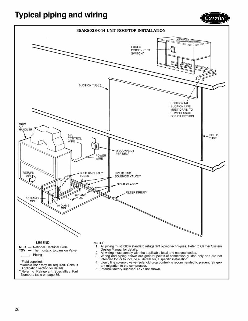
26
Typical piping and wiring
38AKS028-044 UNIT ROOFTOP INSTALLATION
LEGEND
*Field supplied.†Double riser may be required. ConsultApplication section for details.
**Refer to Refrigerant Specialties PartNumbers table on page 35.
NEC — National Electrical CodeTXV — Thermostatic Expansion Valve
Piping
NOTES:1. All piping must follow standard refrigerant piping techniques. Refer to Carrier System
Design Manual for details. 2. All wiring must comply with the applicable local and national codes.3. Wiring and piping shown are general points-of-connection guides only and are not
intended for, or to include all details for, a specific installation.4. Liquid line solenoid valve (solenoid drop control) is recommended to prevent refriger-
ant migration to the compressor.5. Internal factory-supplied TXVs not shown.
a38-6599tf

27
38AKS028-044 UNIT GROUND-LEVEL INSTALLATION
LEGEND
*Field supplied.
TXV — Thermostatic Expansion ValvePiping
NOTES:1. All piping must follow standard refrigerant piping techniques. Refer to Carrier System
Design Manual for details.2. All wiring must comply with the applicable local and national codes.3. Wiring and piping shown are general points-of-connection guides only and are not intended
for, or to include all details for, a specific installation.4. Liquid line solenoid valve (solenoid drop control) is recommended to prevent refrigerant
migration to the compressor.
a38-3931tf

28
38AKS028-044 UNIT ELECTRICAL DATA — 60 Hz
LEGEND
*Units are suitable for use on electrical systems where voltage supplied tothe unit terminals is not below or above the listed minimum and maximumlimits.
†Fuse or HACR circuit breaker.**The 380-v units are export models not listed with UL or UL, Canada.NOTES:
1. Maximum instantaneous current flow during starting is the point in thestarting sequence where the sum of the LRA for the starting compres-sor, plus the total RLA for all running compressors, plus the total FLAfor all running motors is maximum.
2. Minimum circuit amps complies with National Electrical Code (NEC),Section 430-24.
38AKS028-044 UNIT ELECTRICAL DATA — 50 Hz
LEGEND
*Unit voltage 346-3-50 is available through special order only.†Units are suitable for use on electrical systems where voltage supplied to
unit terminals is not below or above listed minimum and maximum limits.
**Fuse or HACR circuit breaker.NOTES:
1. MCA and MOCP values are calculated in accordance with NEC(National Electric Code) (U.S.A. Standard), Article 440.
2. Motor FLA and RLA values are established in accordance with UL(Underwriters Laboratories) Standard 1995 (U.S.A. standard).
3. The 230-v and 346-v units are part-wind-start units; the value undercompressor LRA is for the first winding energized. The 400-v units areacross-the-line-start units; value shown is for all windings energized.
UNIT38AKS
NOMINALVOLTAGE
VOLTAGERANGE* FLA
COMPRESSOR FAN MOTORS POWER SUPPLY
RLA LRA Qty FLA(ea) MCA MOCP† ICF(3 Ph, 60 Hz) Min Max
028
208/230 187 254 102.2 89.8 446
2
6.2 124.6 200 452.2380** 342 418 53.3 45.5 247 3.9 64.7 110 250.9460 414 508 49.8 43.6 223 3.1 60.7 100 226.1575 518 632 43.3 36.5 164 3.4 52.5 80 167.4
034
208/230 187 254 118.4 106.5 506
2
6.2 145.5 250 512.2380** 342 418 60.4 52.6 280 3.9 72.5 125 283.9460 414 508 56.2 50.0 253 3.1 68.7 110 256.1575 518 632 45.3 38.5 176 3.4 54.9 90 179.4
044
208/230 187 254 165.6 147.5 690
3
6.2 203.0 350 702.4380** 342 418 91.2 79.5 382 3.9 111.1 175 389.8460 414 508 74.7 65.4 345 3.1 91.0 150 351.2575 518 632 67.3 57.1 276 3.4 81.5 125 282.8
FLA — Full Load AmpsHACR — Heating, Air Conditioning, and RefrigerationICF — Maximum Instantaneous Current FlowLRA — Locked Rotor AmpsMCA — Minimum Circuit AmpsMOCP — Maximum Overcurrent ProtectionRLA — Rated Load AmpsUL — Underwriters Laboratories
UNIT38AKS
NOMINAL VOLTAGE*(3 Ph, 50 Hz)
VOLTAGE RANGE† COMPRESSOR FAN MOTOR POWER SUPPLYMin Max RLA LRA Qty FLA (ea) MCA MOCP**
028346 311 380 44.9 155
24.4 64.9 100
230 198 254 76.9 205 6.4 109.0 175380/415 342 440 43.6 223 3.0 60.5 100
034346 311 380 53.9 176
24.4 76.1 125
230 198 254 85.9 220 6.4 120.2 200380/415 342 440 50.0 253 3.0 68.5 110
044346 311 380 79.5 240
34.4 112.6 175
230 198 254 105.1 327 6.4 150.6 250380/415 342 440 65.4 345 3.0 90.8 150
FLA — Full Load AmpsHACR — Heating, Air Conditioning, RefrigerationLRA — Locked Rotor AmpsMCA — Minimum Circuit Amps per NEC Section 430-24MOCP — Maximum Overcurrent ProtectionNEC — National Electrical Code (U.S.A. Standard)RLA — Rated Load Amps (Compressor)
Electrical data

29
Operating sequences38AKS028-044 — When space thermostat calls forcooling, the no. 1 condenser fan and compressor startsafter control module (CM) initial time delay of 7 seconds. Ifan optional airflow switch is used, compressor and no. 1condensing fan will not start until sufficient indoor airflowhas closed the switch. After 7 seconds the compressorstarts and the liquid line solenoid valve (for solenoid dropcontrol) opens. The crankcase heater is deenergized. If thehead pressure reaches 260 psig (1793 kPag), the secondcondenser fan starts.
If cooling demand is low, suction pressure at the com-pressor drops. As the pressure drops, the compressorunloads 1 or 2 banks of cylinders as required. If coolingdemand is high and 2-stage operation is used, the secondstep of the thermostat activates the capacity control liquidline solenoid which activates the second stage evaporatorcoil. The compressor cylinders load or unload in responseto compressor suction pressure to meet evaporator load.
For two and a half minutes after the compressor starts,the low-pressure switch (LPS) is ignored. If the LPS tripsduring the first 21/2 minutes of operation, the compressorremains operational. If a high-pressure switch (HPS) tripsat any time, or the LPS trips after 21/2 minutes, thecompressor cannot restart until the 3-minute CM anti-short cycle timer expires.
As the space cooling load is satisfied, the second stageof the thermostat opens, and closes the field-supplied
capacity control liquid line solenoid valve to deactivate thesecond stage coil. The compressor adjusts the number ofactive cylinders to meet the new load. When the spacetemperature is satisfied, the first stage of the thermostatopens and the control relay opens. This closes the sole-noid drop control valve. The compressor stops and thecrankcase heater is energized, preventing refrigerant frommigrating to the compressor during the off cycle solenoiddrop refrigerant control). The CM anti-short-cycling timeris energized and runs for approximately 3 minutes. Duringthis time, the compressor is not able to restart.Restart — Manual reset of the 24-v control circuit is re-quired if unit is shut down by any of the safety devices. Ap-plicable devices include the high pressure switch (HPS),low-pressure switch (LPS), oil-pressure switch (OPS), andcompressor overtemperature protection (COTP) switch.To restart the unit after the unit has been shut down, raisethe thermostat set point above the space temperature(thereby removing the call for cooling) and then lower theset point back to the desired setting.
If unit circuit breakers trip during unit shutdown, theymust be reset manually.
Causes of complete unit shutdown:• interruption of supplied power• open compressor overtemperature protection (COTP)• compressor electrical overload protection (CB1 or CB2) • open high-pressure or low-pressure safety switches• open oil pressure switch
Controls
AUTO
Pm
COOL
HEAT
Carrier®
CARRIER CONTROLSDEBONAIR® COMMERCIAL
PROGRAMMABLE THERMOSTAT EDGE® PRO THERMOSTAT
PREMIERLINK™ COMMUNICATING CONTROLS
a33-638tf
a33-9191

30
Typical control wiring schematics
(115
v)
(24
v)
→ T
YPIC
AL
38A
KS028-0
44 U
NIT
S W
ITH
SIN
GLE
AIR
HA
ND
LER
LEG
EN
DA
FS
—A
irflo
w S
witc
hC
B—
Circ
uit B
reak
erE
QU
IP—
Equ
ipm
ent
GN
D—
Gro
und
LL
SV
—Li
quid
Lin
e S
olen
oid
Val
veT
B—
Term
inal
Blo
ckT
STA
T—
The
rmos
tat
Fie
ld C
ontr
ol W
iring
Fact
ory
Wiri
ngF
ield
Pow
er W
iring
NO
TE
S:
1.Fa
ctor
y w
iring
in a
ccor
danc
e w
ith N
EC
(N
atio
nal E
lect
rical
Cod
e).
Any
fie
ld m
odifi
catio
ns o
rad
ditio
ns m
ust b
e in
com
plia
nce
with
all
appl
icab
le c
odes
.2.
All
field
int
erlo
ck c
onta
cts
mus
t ha
ve m
inim
um r
atin
g of
180
-va
pilo
t du
ty p
lus
capa
city
requ
ired
for
field
-inst
alle
d eq
uipm
ent.
All
field
inte
rlock
con
tact
s in
the
24-v
con
trol
circ
uit m
ust
have
min
imum
rat
ing
of 7
0-va
pilo
t dut
y pl
us c
apac
ity r
equi
red
for
field
-inst
alle
d eq
uipm
ent.
3.F
or i
nter
nal
unit
wiri
ng,
refe
renc
e w
iring
boo
k or
uni
t w
iring
lab
el d
iagr
am.
TB
2 is
115
-1-6
0,T
B3
is 2
4-1-
60.
4.T
he f
ollo
win
g co
mpo
nent
s ar
e no
t lo
cate
d in
the
38A
KS
uni
t co
ntro
l bo
x: L
LS1,
LLS
2, f
ield
cont
rol t
herm
osta
t, A
FS
, ala
rm s
hut-
off s
witc
h, a
nd a
larm
or
light
.
a38-7053.eps
509

31
38AKS028-044 UNIT — 60 Hz
NOTES:1. Connect TRAN2 to terminal H3 for 230-v, H4 for 460-v, and H2 for 575-v units. If 208/230-v units are
run with a 208-v power supply, connect to terminal H2.2. Connect TRAN1 to ORN lead for 230-v, BLK lead for 460-v, and WHT lead for 575-v units. If 208/
230-v units are run with a 208-v power supply, connect to RED lead.3. Compressor and fan motors thermally protected. Three phase motors protected against primary
single phasing conditions.4. Replacement of original wires must be with type 90 C wire or its equivalent.5. Line # indicates location of contacts: #,# signifies single pole double throw contacts: # signifies a
normally closed contact: # signifies a normally open contact.6. Factory wiring is in accordance with National Electrical Code (NEC). Field modifications or additions
must be in compliance with all applicable codes.7. Wiring for field power supply must be rated 60 C. Use copper, copper-clad aluminum or aluminum
conductors.8. Terminals G/6, Y2/3 and C/7 of TB3 are for class 2 (24-v) field external interlock connections. Class
1 field interlock conntacts must have minimum rating of 180-va, 220-v, 50/60 Hz pilot duty. Class 2field interlock conntacts must have minimum rating of 70-va, 24-v, 50/60 Hz pilot duty.
9. Thermostat for standard units:HH01AD042, HH07AT172 and HH07AT174.Subbase:HH93AZ042, HH93AZ176 and HH93AZ180.
10. Control module internal illustrated to indicate components orientational sequence. All items illus-trated are theoretically represented as internal to component.
11. The factory-supplied LLSV drop control is shipped with the 38AKS unit but field installed at theindoor unit.
12. To change fan rotation, interchange fan motor connections 1 and 3.
LEGEND
ATS — Air Temperature SwitchC — Contactor, CompressorCB — Circuit BreakerCH — Crankcase HeaterCM — Control ModuleCOMP — CompressorCOTP — Compressor Overtemperature ProtectionEQUIP — EquipmentFC — Fan ContactorFCPS — Fan Cycling Pressure SwitchFM — Fan MotorFR — Fan RelayFU — FuseGND — GroundHPS — High Pressure SwitchLED — Light-Emitting DiodeLLSV — Liquid Line Solenoid ValveLPS — Low Pressure SwitchOPS — Oil Pressure SwitchTB — Terminal BlockTRAN — Transformer
Terminal Block ConnectionMarkerd TerminalUnmarked TerminalMarked SpliceUnmarked SpliceFactory WireField Power WiringIndicates Common Potential, Does Not Represent Wiring.
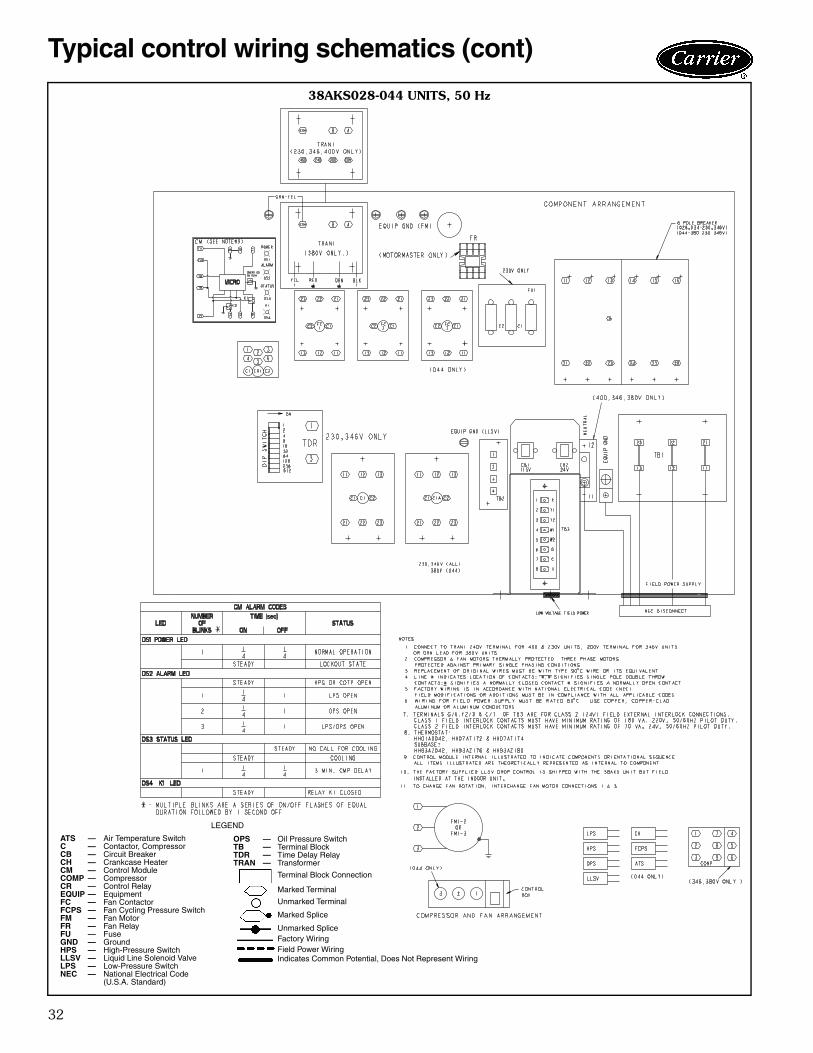
32
Typical control wiring schematics (cont)
38AKS028-044 UNITS, 50 Hz
LEGEND
OPS — Oil Pressure SwitchTB — Terminal BlockTDR — Time Delay RelayTRAN — Transformer
Terminal Block Connection
Marked Terminal
Unmarked Terminal
Marked Splice
Unmarked SpliceFactory WiringField Power WiringIndicates Common Potential, Does Not Represent Wiring
ATS — Air Temperature SwitchC — Contactor, CompressorCB — Circuit BreakerCH — Crankcase HeaterCM — Control ModuleCOMP — CompressorCR — Control RelayEQUIP — EquipmentFC — Fan ContactorFCPS — Fan Cycling Pressure SwitchFM — Fan MotorFR — Fan RelayFU — FuseGND — GroundHPS — High-Pressure SwitchLLSV — Liquid Line Solenoid ValveLPS — Low-Pressure SwitchNEC — National Electrical Code
(U.S.A. Standard)

33
InstallationSelect equipment to match or to be slightly less than peakload. This provides better humidity control, less unit cy-cling, and less part-load operation.
When selecting vapor line sizes, oil return should beevaluated, particularly at part-load conditions.
The indoor fan must always be operating when outdoorfan is operating.
Unit cycles should be limited to 3 or less per hour.Multiple outdoor units may be used with a single indoor
unit; this involves multiple refrigeration circuits.
To minimize return-air temperature extremes, use theequipment room as a return-air plenum when applyingVAV systems with supply-to-return air recycle as used withVVT® control systems.
Indoor equipment should be selected at no less than300 cfm/ton (40 L/s per kW).
OPERATING LIMITS
MINIMUM OUTDOOR-AIR OPERATINGTEMPERATURE (F)
MAXIMUM LIQUID LIFT
REFRIGERANT PIPING SIZESSINGLE SUCTION RISERS, 60 Hz
LEGEND
*Requires a double suction riser, if evaporator is below condensing unit. See Dou-ble Suction Riser, 60 Hz table below.NOTE: Liquid and suction line sizes are OD (in.)
DOUBLE SUCTION RISERS, 60 Hz
NOTE: A, B, and C dimensions are referenced in the Suction Line Piping figure.
SINGLE SUCTION RISERS, 50 Hz
LEGEND
*Requires a double suction riser, if evaporator is below condensing unit. See Dou-ble Suction Riser, 50 Hz table below.NOTE: All line sizes are inches OD.
DOUBLE SUCTION RISERS, 50 Hz
NOTE: A, B, and C dimensions are referenced in the Suction Line Piping figure.
IMPORTANT: When application is in a variable air vol-ume (VAV) system, total building load is not the sum ofthe individual peak loads. If individual peak loads aresummed, the equipment tends to be oversized for theload.
IMPORTANT: Condensing units applied in VVT or VAVsystems must have field-supplied and installed accumu-lators. Order part number 38AK-5---410 from ServiceParts.
Maximum Outdoor Ambient 115 F (46 C)
Minimum Outdoor AmbientAdditional head pressure control may be required below 35 F(1.7 C) outdoor ambient.
Minimum Return-Air Temperature 55 F (12.8 C)Maximum Return-Air Temperature 95 F (35 C)Normal Acceptable Saturation
Suction Temperature Range 30 to 55 F (1.1 to 12.8 C)
Maximum Discharge Temperature 295 F (146 C)Minimum Discharge Superheat 60 F (15.6 C)
UNIT38AKS
COMPRCAPACITY
(%)
STANDARDCOND
TEMP, F (C)
MIN OUTDOOR TEMP, F (C)
StandardUnit
Low AmbientControl
028100 90 (32) 31 (-0.6)
–20 (-29)
67 80 (27) 35 (1.7)33 70 (21) 43 (6.1)
034100 90 (32) 30 (-1.1)
67 80 (27) 34 (1.1)33 70 (21) 42 (3.5)
044100 90 (32) 25 (-3.9)
67 80 (27) 30 (-1.1)33 70 (21) 35 (1.7)
UNIT 38AKS MAX LIFT, ft (m)028 76 (23) 034 67 (20)044 76 (23)
UNIT38AKS
LENGTH OF INTERCONNECTING PIPING, Ft (m)16-25
(4.9-7.6)26-50
(7.9-15.2)51-75
(15.5-22.8)76-100
(23.2-30.5)101-200
(30.8-60.9)L S L S L S L S L S
028 7/8 15/8 7/8 21/8* 7/8 21/8* 7/8 21/8* 7/8 21/8*034 7/8 21/8 7/8 21/8 7/8 21/8 11/8 21/8 11/8 25/8*044 7/8 21/8 7/8 21/8 11/8 25/8* 11/8 25/8* 11/8 25/8*
L — Liquid LineS — Suction Line
UNIT38AKS
LENGTH OF INTERCONNECTING PIPING, Ft (m)26-50
(7.9-15.2)51-75
(15.5-22.8)76-100
(23.2-30.5)101-200
(30.8-60.9)A B C A B C A B C A B C
028 13/8 15/8 21/8 13/8 15/8 21/8 13/8 15/8 21/8 13/8 15/8 21/8034 — — — — — — — — — 15/8 21/8 25/8044 — — — 15/8 21/8 25/8 15/8 21/8 25/8 15/8 21/8 25/8
UNIT38AKS
LENGTH OF INTERCONNECTING PIPING — Ft (m)16-25
(4.9-7.6)26-50
(7.9-15.2)51-75
(15.5-22.8)76-100
(23.2-30.5)101-200
(30.8-60.9)L S L S L S L S L S
028 7/8 15/8 7/8 21/8* 7/8 21/8* 7/8 21/8* 7/8 21/8*034 7/8 21/8 7/8 21/8 7/8 21/8 11/8 21/8 11/8 25/8*044 7/8 21/8 7/8 21/8 11/8 25/8* 11/8 25/8* 11/8 25/8*
L — Liquid LineS — Suction Line
*IMPORTANT — If condensing unit is above air handler, a doublesuction riser is required. See table below for sizing.
UNIT38AKS
LENGTH OF INTERCONNECTING PIPING — Ft (m)26-50
(7.9-15.2)51-75
(15.5-22.8)76-100
(23.2-30.5)101-200
(30.8-60.9)A B C A B C A B C A B C
028 15/8 15/8 21/8 15/8 15/8 21/8 15/8 15/8 21/8 15/8 15/8 21/8034 — — — — — — — — — 15/8 21/8 25/8044 — — — 15/8 21/8 25/8 15/8 21/8 25/8 15/8 21/8 25/8
Application data
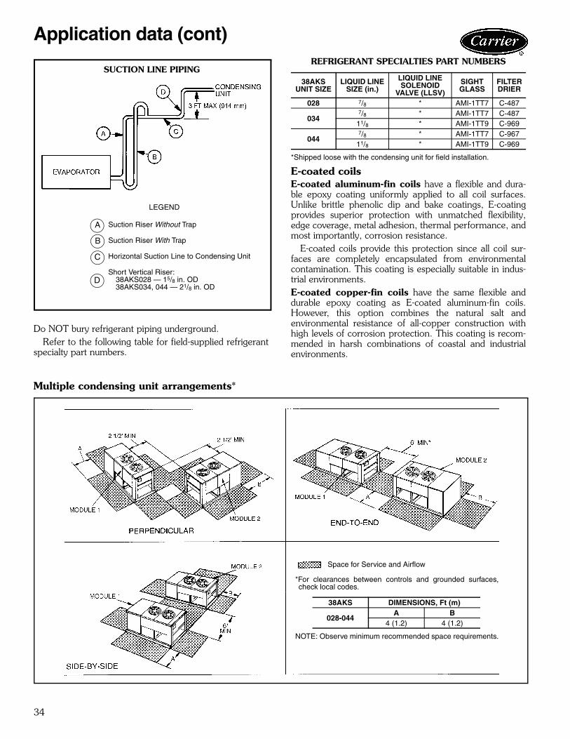
34
Do NOT bury refrigerant piping underground.Refer to the following table for field-supplied refrigerant
specialty part numbers.
REFRIGERANT SPECIALTIES PART NUMBERS
*Shipped loose with the condensing unit for field installation.
E-coated coilsE-coated aluminum-fin coils have a flexible and dura-ble epoxy coating uniformly applied to all coil surfaces.Unlike brittle phenolic dip and bake coatings, E-coatingprovides superior protection with unmatched flexibility,edge coverage, metal adhesion, thermal performance, andmost importantly, corrosion resistance.
E-coated coils provide this protection since all coil sur-faces are completely encapsulated from environmentalcontamination. This coating is especially suitable in indus-trial environments.E-coated copper-fin coils have the same flexible anddurable epoxy coating as E-coated aluminum-fin coils.However, this option combines the natural salt andenvironmental resistance of all-copper construction withhigh levels of corrosion protection. This coating is recom-mended in harsh combinations of coastal and industrialenvironments.
Multiple condensing unit arrangements*
38AKS UNIT SIZE
LIQUID LINE SIZE (in.)
LIQUID LINE SOLENOID
VALVE (LLSV)
SIGHT GLASS
FILTER DRIER
028 7/8 * AMI-1TT7 C-487
0347/8 * AMI-1TT7 C-487
11/8 * AMI-1TT9 C-969
0447/8 * AMI-1TT7 C-967
11/8 * AMI-1TT9 C-969
Application data (cont)
SUCTION LINE PIPING
LEGEND
Suction Riser Without Trap
Suction Riser With Trap
Horizontal Suction Line to Condensing Unit
Short Vertical Riser:38AKS028 — 15/8 in. OD38AKS034, 044 — 21/8 in. OD
A
B
C
D
Space for Service and Airflow
*For clearances between controls and grounded surfaces,check local codes.
NOTE: Observe minimum recommended space requirements.
38AKS DIMENSIONS, Ft (m)
028-044A B
4 (1.2) 4 (1.2)

35
Commercial Air-Cooled Condensing UnitsHVAC Guide SpecificationsSize Range: 25 to 40 Tons Nominal at 60 Hz
(82.8 to 127.0 kW Nominal at 50 Hz)Carrier Model Number: 38AKSPart 1 — General1.01 SYSTEM DESCRIPTION
Outdoor-mounted, air-cooled condensing unit suit-able for on-the-ground or rooftop installation. Unitshall consist of a semi-hermetic reciprocating com-pressor, an air-cooled coil, propeller-type condenserfans, and a control box. Unit shall discharge supplyair upward as shown on contract drawings. Unitshall be used in a refrigeration circuit to match apackaged air-handling unit.
1.02 QUALITY ASSURANCEA. Unit performance shall be rated in accordance with
ARI Standard 365, latest edition.B. Unit shall be manufactured in a facility registered to
the ISO 9001:2000 manufacturing quality standard.C. Unit construction shall comply with ANSI/ASHRAE
15 latest revision safety code and comply with NEC(U.S.A. standards).
D. Unit shall be constructed in accordance with ULstandards and shall carry the UL and UL, Canadalabel of approval.
E. Unit cabinet shall be capable of withstanding500-hour salt spray exposure per ASTM B117(scribed specimen).
F. Air-cooled condenser coils shall be leak tested at150 psig (1034 kPa) and pressure tested at480 psig (3310 kPa).
1.03 DELIVERY, STORAGE AND HANDLINGUnit shall be shipped as single package only, andshall be stored and handled per unit manufacturer’srecommendations.
1.04 WARRANTY (FOR INCLUSION BY SPECIFYINGENGINEER.)
Part 2 — Products2.01 EQUIPMENT
A. General:Factory assembled, single piece, air-cooled condens-ing unit. Contained within the unit enclosure shall beall factory wiring, piping, controls, compressor,nitrogen holding charge, and special featuresrequired prior to field start-up.
B. Unit Cabinet:1. Unit cabinet shall be constructed of galvanized
steel, bonderized and coated with a prepainted,baked enamel finish.
2. End unit access panel shall be hinged for com-pressor and control box service access.
3. Lifting holes shall be provided to facilitaterigging.
C. Fans:1. Condenser fans shall be direct-drive propeller
type, discharging air vertically upward.2. Condenser fan motors shall be totally enclosed,
3-phase type with class B insulation and perma-nently lubricated bearings.
3. Shafts shall have inherent corrosion resistance.4. Fan blades shall be statically and dynamically
balanced.5. Condenser fan openings shall be equipped with
PVC-coated steel wire safety guards.D. Compressor:
1. Compressor shall be serviceable, reciprocating,semi-hermetic type.
2. Compressor shall be equipped with an automat-ically reversible oil pump, operating oil charge,suction and discharge shutoff valves, and aninsert-type, factory-sized crankcase heater tocontrol oil dilution.
3. Compressor shall be mounted on spring vibra-tion isolators with an isolation efficiency of noless than 95%.
4. Compressor speed shall not exceed 1750 rpm(60 Hz units) or 1450 rpm (24.2 r/s)(50 Hz units).
5. Compressor shall unload using suction cutoffunloading (electrical solenoid unloading shall beavailable as an accessory).
E. Condenser Coil:1. Condenser coil shall be air cooled, circuited for
integral subcooler.2. Coil shall be constructed of aluminum fins
mechanically bonded to internally grooved,seamless copper tubes which are then cleaned,dehydrated, and sealed. Epoxy phenolic fincoating shall be available as an option.
3. Coil shall be protected by a sheet metal casingto eliminate the need for wind baffles for lowambient temperature operation.
4. Coil shall be protected to avoid damage due tothe elements and vandalism.
F. Refrigeration Components:Refrigeration circuit components shall include hotgas muffler, high-side pressure relief device, liquidline shut-off valve, suction and discharge shutoffvalves, nitrogen holding charge, and compressor oil.
G. Controls and Safeties:1. Minimum control functions shall include:
a. Power and control terminal blocks.b. Three-minute anti-short-cycling timer to pre-
vent compressor short-cycling.c. Lockout on auto-reset safety until reset from
thermostat.
Guide specifications

36
d. Capacity control on the compressor shall beby suction cutoff unloaders in response tocompressor suction pressure. Electric sole-noid unloading shall be available as anaccessory.
e. A 115-v solenoid shall be provided for sole-noid drop control.
f. Head pressure control to 35 F (60 Hz units)or 31 F (-6 C) (50 Hz units) by fan cycling.One condenser fan shall be cycled by dis-charge pressure to maintain proper headpressure.
g. Winter start control to prevent nuisance trip-outs at low ambient temperatures.
2. Minimum safety devices shall include:Automatic reset (after resetting first at controlcircuit power supply)a. High discharge-pressure cutout.b. Low suction-pressure cutout.c. Condenser fan motors to be protected
against overload or single-phase conditionby internal overloads.
Manual reset at the unita. Low oil-pressure cutout.b. Compressor electrical overload protection
through the use of definite-purpose contac-tors and calibrated, ambient-compensated,magnetic-trip circuit breakers. Circuit break-ers shall open all 3 phases in the event of anoverload in any one of the phases or asingle-phase condition.
H. Operating Characteristics:1. The capacity of the condensing unit shall meet
or exceed at a suction temperature of. The power consumption at full load
shall not exceed kW.2. The combination of the condensing unit and
the evaporator or fan coil unit shall have a totalnet cooling capacity of or greater atconditions of: entering-air temperatureat the evaporator at wet bulb and
dry bulb, and air entering the condens-ing unit at .
3. The system shall have an EER of orgreater at standard ARI conditions.
I. Electrical Requirements:1. Nominal unit electrical characteristics shall be
v, 3-ph, 50 or 60 Hz were applicable.The unit shall be capable of satisfactory opera-tion within voltage limits of v to
v. 2. Unit electrical power shall be single point
connection.3. Unit control circuit shall contain a 24-v trans-
former for unit control, with capacity to operatean indoor fan interlock.
J. Special Features:1. Low-Ambient Control:
Control shall regulate fan motor speed inresponse to the saturated condensing tempera-ture of the unit. The control shall be capableof maintaining a condensing temperature of100 F ± 10° F (37.8 C ± 5.6 ° C) with outdoortemperatures at –20 F (–28 C) (motor changerequired).
2. Electric Solenoid Unloader:Unloader valve piston, coil, and hardware shallbe supplied to convert any pressure-operatedcompressor unloader to 115-v (60 Hz units) or220-v (50 Hz units) electric unloading. Acces-sory ModuPanel™ control box or field-suppliedstep controller shall be provided for electricalunloading.
3. Hot-Gas Bypass:A hot-gas bypass valve and a pilot line solenoidvalve shall be provided for low-load operation ofthe refrigeration system.
4. Part-Winding Start:Part-winding start shall be provided to reduceinrush current and locked rotor amps onstart-up (208/230-3-60 and 220-3-50 unitvoltages only).
5. Gage Panel:A gage panel package shall be provided whichincludes a suction and discharge pressure gagefor the refrigerant circuit.
6. ModuPanel Control Box:Control box shall be provided to allow systemto operate as a variable air volume (VAV)system.
7. Optional Condenser Coil Materials:a. Pre-Coated Aluminum-Fin Coils:
Shall have a durable epoxy-phenolic coatingto provide protection in mildly corrosivecoastal environments. Coating shall beapplied to the aluminum fin stock prior tothe fin stamping process to create an inertbarrier between the aluminum fin and cop-per tube. Epoxy-phenolic barrier shall mini-mize galvanic action between dissimilarmetals.
b. Copper-Fin Coils:Shall be constructed of copper-fins mechani-cally bonded to copper-tubes and coppertube sheets. Galvanized steel tube sheetsshall not be acceptable. A polymer strip shallprevent coil assembly from contacting sheetmetal coil pan to minimize potential for gal-vanic corrosion between the coil and pan.All-copper construction shall provide protec-tion in moderate coastal environments.
Guide specifications (cont)

37
c. E-Coated Aluminum-Fin Coils:Shall have a flexible epoxy polymer coatinguniformly applied to all coil surface areaswithout material bridging between fins.Coating process shall ensure complete coilencapsulation. Color shall be high glossblack with gloss requirements of 60° of 65to 90% per ASTM D523-89. Uniform dryfilm thickness from 0.8 to 1.2 mil on all sur-face areas including fin edges. Superiorhardness characteristics of 2H per ASTMD3363-92A and cross hatch adhesion of4B-5B per ASTM D3359-93. Impact resis-tance shall be up to 160 in./lb (ASTMD2794-93). Humidity and water immersionresistance shall be up to a minimum of 1000and 250 hours respectively (ASTM D2247-92 and ASTM D870-92). Corrosion durabil-ity shall be confirmed through testing to noless than 1000 hours salt spray per ASTMB117-90. Coil construction shall be alumi-num fins mechanically bonded to coppertubes.
d. E-Coated Copper-Fin Coils:Shall have a flexible epoxy polymer coatinguniformly applied to all coil surface areaswithout material bridging between fins.Coating process shall ensure complete coilencapsulation. Color shall be high glossblack with gloss requirements of 60° of 65to 90% per ASTM D523-89. Uniform dryfilm thickness from 0.8 to 1.2 mil on all sur-face areas including fin edges. Superior
hardness characteristics of 2H per ASTMD3363-92A and cross hatch adhesion of4B-5B per ASTM D3359-93. Impact resis-tance shall be up to 160 in./lb (ASTMD2794-93). Humidity and water immersionresistance shall be up to a minimum of 1000and 250 hours respectively (ASTM D2247-92 and ASTM D870-92). Corrosion durabil-ity shall be confirmed through testing to noless than 1000 hours salt spray per ASTMB117-90. Coil construction shall be copper-fins mechanically bonded to copper-tubeswith copper tube sheets. Galvanized steeltube sheets shall not be acceptable. A poly-mer strip shall prevent coil assembly fromcontacting sheet metal coil pan to maintaincoating integrity and minimize corrosionpotential between the coil and pan.
8. PremierLink™ Controller:This control will function with CCN (CarrierComfort Network®) and ComfortVIEW™ soft-ware. It shall also be compatible withComfortLink™ controllers. It shall be ASHRAE62-99 compliant and Internet ready. It shallaccept a CO2 sensor in the conditioned spaceand be demand controlled ventilation (DCV)ready. The communication rate must be 38.4Kor faster. It shall include an integrated econo-mizer controller.
9. Suction Line Accumulator:Accumulator can be provided for VAV, VVT®,or long line CV applications.


Manufacturer reserves the right to discontinue, or change at any time, specifications or designs without notice and without incurring obligations.Pg 40 Catalog No. 04-52380007-01 Printed in U.S.A. Form 38AKS-2PD
Replaces: 38AKS-1PDSection 7Tab 7a
Carrier Corporation • Syracuse, New York 13221 509 3-09