Product Data Sheet Catalog 2006 - 2007 Rosemount 2088 Rosemount … · 2014-11-04 · Rosemount 305...
12
Product Data Sheet 00813-0100-4690, Rev HA Catalog 2006 - 2007 Rosemount 2088 www.servinstrumentation.fr A TRADITION OF EXCELLENCE IN PERFORMANCE FROM THE INDUSTRY LEADERS • Absolute and gage pressure ranges from 0–1.5 psi to 0–4,000 psi (0–0.1 to 0–276 bar) • 0.10% reference accuracy, including linearity, hysteresis, and repeatability • 20:1 turndown • Lightweight, compact size makes for easy installation and handling • 0.075% High accuracy option Contents Specifications . . . . . . . . . . . . . . . . . . . . . . . . . . . . . . . . . . . . . . . . . . . . . . . . . . . . . . page 3 Product Certifications . . . . . . . . . . . . . . . . . . . . . . . . . . . . . . . . . . . . . . . . . . . . . . . . page 5 Dimensional Drawings. . . . . . . . . . . . . . . . . . . . . . . . . . . . . . . . . . . . . . . . . . . . . . . . page 7 Ordering Information . . . . . . . . . . . . . . . . . . . . . . . . . . . . . . . . . . . . . . . . . . . . . . . . . page 8 Configuration Data Sheet . . . . . . . . . . . . . . . . . . . . . . . . . . . . . . . . . . . . . . . . . . . . page 10 Rosemount 2088 Absolute and Gage Pressure Transmitter
Transcript of Product Data Sheet Catalog 2006 - 2007 Rosemount 2088 Rosemount … · 2014-11-04 · Rosemount 305...
Product Data Sheet00813-0100-4690, Rev HA
Catalog 2006 - 2007 Rosemount 2088
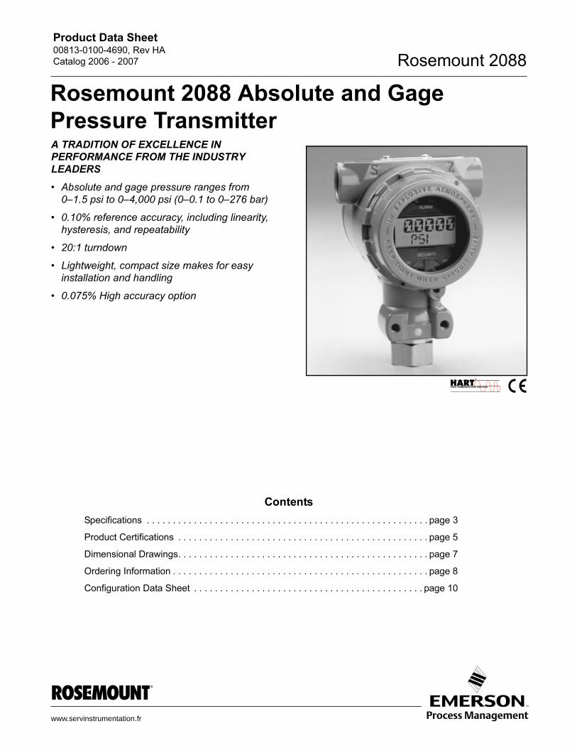
Rosemount 2088 Absolute and Gage
Pressure Transmitter
A TRADITION OF EXCELLENCE INPERFORMANCE FROM THE INDUSTRY
LEADERS
• Absolute and gage pressure ranges from
0–1.5 psi to 0–4,000 psi (0–0.1 to 0–276 bar)
• 0.10% reference accuracy, including linearity,
hysteresis, and repeatability
• 20:1 turndown
• Lightweight, compact size makes for easy
installation and handling
• 0.075% High accuracy option
www.se
Contents
Specifications . . . . . . . . . . . . . . . . . . . . . . . . . . . . . . . . . . . . . . . . . . . . . . . . . . . . . . page 3
Product Certifications . . . . . . . . . . . . . . . . . . . . . . . . . . . . . . . . . . . . . . . . . . . . . . . . page 5
Dimensional Drawings. . . . . . . . . . . . . . . . . . . . . . . . . . . . . . . . . . . . . . . . . . . . . . . . page 7
Ordering Information . . . . . . . . . . . . . . . . . . . . . . . . . . . . . . . . . . . . . . . . . . . . . . . . . page 8
Configuration Data Sheet . . . . . . . . . . . . . . . . . . . . . . . . . . . . . . . . . . . . . . . . . . . . page 10
rvinstrumentation.fr
HP_Administrateur
serv2

Product Data Sheet00813-0100-4690, Rev HA
Catalog 2006 - 2007Rosemount 2088
Rosemount 2088
The 2088 Smart Pressure Transmitter is an
economical addition to the pressure transmitter line
of instruments. The 2088 is designed with reliability,
long-term performance, and maintainability in mind.
The 2088 maintain a specification conformance of at
least 3�(1). The rugged, reliable performance for
which Emerson Process Management transmitters
are famous, coupled with Smart capabilities, make
these transmitters exceptional values.
The 2088 is available in either gauge or absolute
pressure in pressure ranges to 4,000 psi (275 bar). It
utilizes a solid-state, polysilicon pressure sensor with
a choice of either 316L or Hastelloy isolating
diaphragms. The low oil fill of this design has very
little temperature effect and outstanding accuracy.
Features
The 2088 provides accurate, stable, and reliable
pressure measurement in difficult applications. Its
small compact design allows it to be directly
connected to a process - providing a quick, easy, and
cost effective installation.
The 2088 standard process connection is 1/2 inch
NPT but a variety of optional connections are
available. Optional connections range from multiple
threaded connections to our full line of manifolds and
remote diaphragm seals that provide solutions for
virtually any connection.
The 2088 also features an optional, fully configurable
LCD that displays pressure and diagnostic
information. The information displayed is directly
from the microprocessor which accounts for its
accuracy and reliability.
Rosemount Pressure Solutions
Rosemount 3051S Series of InstrumentationScalable pressure, flow and level measurement solutions improve
installation and maintenance practices.
Rosemount 3095MV Mass Flow TransmitterAccurately measures differential pressure, static pressure and
process temperature to dynamically calculate fully compensated
mass flow.
Rosemount 305 and 306 Integral ManifoldsFactory-assembled, calibrated and seal-tested manifolds reduce
on-site installation costs.
Rosemount 1199 Diaphragm SealsProvides reliable, remote measurements of process pressure and
protects the transmitter from hot, corrosive, or viscous fluids.
Annubar Flowmeter Series: Rosemount 3051SFA,
3095MFA, and 485
The state-of-the-art, fifth generation Rosemount 485 Annubar
combined with the 3051S or 3095MV MultiVariable transmitter
creates an accurate, repeatable and dependable insertion-type
flowmeter.
Compact Orifice Flowmeter Series: Rosemount
3051SFC, 3095MFC, and 405
Compact Orifice Flowmeters can be installed between existing
flanges, up to a Class 600 (PN100) rating. In tight fit applications,
a conditioning orifice plate version is available, requiring only two
diameters of straight run upstream.
Integral Orifice Flowmeter Series: Rosemount
3051SFP, 3095MFP, and 1195
These integral orifice flowmeters eliminate the inaccuracies that
become more pronounced in small orifice line installations. The
completely assembled, ready to install flowmeters reduce cost and
simplify installation.
Orifice Plate Primary Element Systems: Rosemount
1495 and 1595 Orifice Plates, 1496 Flange Unions and
1497 Meter Sections
A comprehensive offering of orifice plates, flange unions and
meter sections that is easy to specify and order. The 1595
Conditioning Orifice provides superior performance in tight fit
applications.
(1) Sigma (�) is a statistical symbol to designate the stan-
dard deviation from the mean value of normal distribu-
tion.
2
Product Data Sheet00813-0100-4690, Rev HA
Catalog 2006 - 2007 Rosemount 2088
Specifications
Performance Specifications(Zero-based spans, reference conditions, silicone oil fill, and 316L
SST isolating diaphragm.)
Reference Accuracy
• ±0.10% of calibrated span. Includes combined effects of
linearity, hysteresis, and repeatability
• ±0.075% of calibrated span (high accuracy option)
Ambient Temperature Effect
Expressed as a total effect per 50 °F (28 °C)
Total effect includes zero and span effects.
± (0.15% URL + 0.15% of span) from –40 °F to 185 °F
(-40 °C to 85 °C)
Stability
±0.10% of URL for 12 months
Vibration Effect
Less than ±0.1% of URL when subjected to vibration of: peak to
peak constant displacement of 4 mm (5–15 Hz) and constant
acceleration of 2 g (15–150 Hz) and 1 g (150–2000 Hz).
Power Supply Effect
Less than 0.01% of calibrated span per volt
Mounting Position Effect
Zero shift of up to 1.2 inH2O (0.30 kPa), which can be calibrated
out. No span effect.
RFI Effect
Less than ±0.25% of upper range limit from
20–1000 MHz at 30 V/m with leads in conduit. Less than ±0.25%
of upper range limit from 20-1000 MHz at 10 V/m with unshielded
twisted pair (no conduit).
Transient Protection Limits
IEEE 587 Category B
6 kV Crest (1.2 � 50 �s)
3 kA Crest (8 � 20 �s)
6 kV Crest (0.5 �s by 100 kHz)
IEEE 472
SWC 2.5 kV Crest,1 MHz waveform
General Specifications
Tested to IEC 801-3
Functional Specifications
Service
Liquid, gas, and vapor applications
Ranges
Output
Code S: 4–20 mA dc
Code N: 1-5 volt dc, low power
(Outputs are directly proportional to the input pressure)
Rangedown
20 to 1
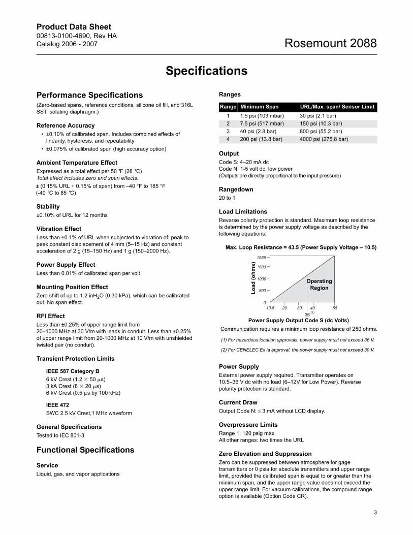
Load Limitations
Reverse polarity protection is standard. Maximum loop resistance
is determined by the power supply voltage as described by the
following equations:
Power Supply
External power supply required. Transmitter operates on
10.5–36 V dc with no load (6–12V for Low Power). Reverse
polarity protection is standard.
Current Draw
Output Code N: ≤ 3 mA without LCD display.
Overpressure Limits
Range 1: 120 psig max
All other ranges: two times the URL
Zero Elevation and Suppression
Zero can be suppressed between atmosphere for gage
transmitters or 0 psia for absolute transmitters and upper range
limit, provided the calibrated span is equal to or greater than the
minimum span, and the upper range value does not exceed the
upper range limit. For vacuum calibrations, the compound range
option is available (Option Code CR).
Range Minimum Span URL/Max. span/ Sensor Limit
1 1.5 psi (103 mbar) 30 psi (2.1 bar)
2 7.5 psi (517 mbar) 150 psi (10.3 bar)
3 40 psi (2.8 bar) 800 psi (55.2 bar)
4 200 psi (13.8 bar) 4000 psi (275.8 bar)
Lo
ad
(o
hm
s)
Operating
Region
Power Supply Output Code S (dc Volts)
Communication requires a minimum loop resistance of 250 ohms.
(1) For hazardous location approvals, power supply must not exceed 36 V.
(2) For CENELEC Ex ia approval, the power supply must not exceed 30 V.
Max. Loop Resistance = 43.5 (Power Supply Voltage – 10.5)
3

Product Data Sheet00813-0100-4690, Rev HA
Catalog 2006 - 2007Rosemount 2088
4
Compound Range Capability
Select the Compound Range (CR) option for use in negative gage
pressure applications. An enhanced sensor is installed in
transmitters with the CR option code.
Time Response
Time Constant: 200 milliseconds
Dead time: < 0.1 s
Update rate: 20 times per second minimum
Temperature Limits
Process
Silicone fill sensor: –40 to 250 °F (–40 to 121 °C)
Inert fill sensor: –22 to 250 °F (–30 to 121 °C)
Process temperatures above 185 °F (85 °C) require derating
the ambient limits by a 1.5:1 ratio:
Ambient:
–40 to 185 °F (–40 to 85 °C)
–4 to 175 °F (–20 to 80 °C) with LCD display
Storage:
–50 to 230 °F (–46 to 110 °C)
–40 to 185 °F (–40 to 85 °C) with LCD display
Humidity Limits
0–100% relative humidity
Volumetric Displacement
Less than 0.00042 cm3
Turn-on Time
2.0 seconds, no warm-up required
Transmitter Security
Activating the transmitter security function prevents changes to the
transmitter configuration, including local zero and span
adjustments. Security is activated by an internal switch.
Failure Mode
If self-diagnostics detect a sensor or microprocessor failure, the
analog signal is driven either high or low to alert the user. High or
low failure mode is user-selectable with a jumper on the
transmitter. The values to which the transmitter drives its output in
failure mode depend on whether it is factory-configured to
standard or NAMUR-compliant operation. The values for each are
as follows:
Physical Specifications
Electrical Connection1/2–14 NPT, M20 � 1.5 (CM20), PG 13.5, or
G 1/2 female (PF 1/2 female) conduit entry
Process Connection1/2–14 NPT female, DIN 16288 G 1/2 male, RC 1/2 female (PT 1/2
female), M20 � 1.5 (CM20) male
Process Wetted Parts
Isolating Diaphragm
316L stainless steel or Hastelloy C-276
Process Connector
316L stainless steel CF-3M (Cast version of 316L SST,
material per ASTM_A743) or Hastelloy C-276
Non-wetted Parts
Electronics Housing
Low-copper aluminum, NEMA 4X, IP65, IP67,CSA enclosure
Type 4X
Paint
Polyurethane
Cover O-rings
Buna-N
Fill Fluid
Silicone or inert fill
Weight
Output Code S and N: Approximately 2.44 lb (1.11 kg)
Tagging
The transmitter is tagged, at no charge, in accordance with
customer requirements. All tags are stainless steel. The standard
tag is permanently attached to the transmitter. Tag character
height is 1/8 in. (0.318 cm). A wired tag is available upon request.
Accessory Block and Bleed Valve (S5 Option)
The Rosemount 306 Integral Manifold is pre-assembled to
transmitter and leak checked.
Standard Operation
Output Code Linear Output Fail High Fail Low
S 3.9 ≤ I ≤ 20.8 I ≥ 21.75 mA I ≤ 3.75 mA
N 0.97 ≤ V ≤ 5.2 V ≥ 5.4 V V ≤ 0.95V
N with Code C2 0.78 ≤ V ≤ 3.44 V ≥ 4.0 V V ≤ 0.77 V
185Process Temp 185–( )
1.5-----------------------------------------------------------–=
Maximum Ambient
Temperature in °F
85Process Temp 85–( )
1.5--------------------------------------------------------–=
Maximum Ambient
Temperature in °C
NAMUR-Compliant
Operation Linear Output Fail High Fail Low
Output Code S 3.8 ≤ I ≤ 20.5 I ≥ 22.5 mA I ≤ 3.6 mA
Product Data Sheet00813-0100-4690, Rev HA
Catalog 2006 - 2007 Rosemount 2088
Product Certifications
Approved Manufacturing LocationsRosemount Inc. — Chanhassen, Minnesota, USA
Emerson Process Management GmbH & Co. — Wessling,
Germany
Emerson Process Management Asia Pacific
Private Limited — Singapore
Beijing Rosemount Far East Instrument Co., LTD — Beijing, China
European Union Directive InformationThe EC declaration of conformity for all applicable European
directives for this product can be found at www.rosemount.com. A
hard copy may be obtained by contacting our local sales office.
ATEX Directive (94/9/EC)Emerson Process Management complies with the ATEX
Directive.
European Pressure Equipment Directive (PED) (97/23/EC)2088/2090 Pressure Transmitters
— Sound Engineering Practice
Electro Magnetic Compatibility (EMC) (89/336/EEC)All 2088/2090 Smart Pressure Transmitter:
EN 50081-1: 1992; EN 50082-2:1995; EN 61326-1:1997
Hazardous Locations Certifications
North American Certifications
Ordinary Location Certification for Factory Mutual
As standard, the transmitter has been examined and tested
to determine that the design meets basic electrical,
mechanical, and fire protection requirements by FM, a
nationally recognized testing laboratory (NRTL) as
accredited by the Federal Occupational Safety and Health
Administration (OSHA).
Factory Mutual (FM) Approvals
E5 Explosion-Proof for Class I, Division 1, Groups B, C, and D.
Dust-Ignition-Proof for Class II, Division 1, Groups E, F, G,
Class III, Division 1, indoor and outdoor (NEMA 4X)
hazardous locations; factory sealed.
I5 Intrinsically safe for use in Class I, Division 1, Groups A, B,
C, D; Class II, Division 1, Groups E, F, and G; and Class III,
Division 1 when connected in accordance with Rosemount
drawing 02088-1018. Non-incendive for Class I, Division 2,
Groups A, B, C, and D.
For input parameters see control drawing 02088-1018.
Canadian Standards Association (CSA)
C6 Explosion-Proof for Class I, Division 1, Groups B, C, and D.
Dust-Ignition-Proof for Class II, Division 1, Groups E, F, G,
Class III, indoor and outdoor hazardous locations. CSA
enclosure Type 4X; factory sealed. Suitable for Class I,
Division 2, Groups A, B, C, and D.
Intrinsically Safe for Class I, Division 1, Groups A, B, C, and
D. Temp. Code T3C. Intrinsically safe when connected with
approved barriers in accordance with Rosemount drawing
02088-1024.
For input parameters see control drawing 02088-1024.
European Certifications
I1 ATEX Intrinsically Safe
Certificate No.: BAS00ATEX1166X II 1 G
EEx ia IIC T5 (Tamb = –55 to 40 °C)
EEx ia IIC T4 (Tamb = –55 to 70°C)
1180
TABLE 1. Input Parameters
Special Conditions for Safe Use (x):
When the optional transient protection terminal block is
installed, the apparatus is not capable of withstanding a
500V rms test to case. This must be taken into account on
any installation in which it is used, for example by assuring
that the supply to the apparatus is galvanically isolated.
N1 ATEX Type n
Certification No.: BAS00ATEX3167X II 3 G
EEx nL IIC T5 (Ta = -40 °C to 70 °C)
Ui = 50 V dc max
Special Conditions for Safe Use (x):
When the optional transient protection terminal block is
installed, the apparatus is not capable of withstanding a 500
V r.m.s. test to case. This must be taken into account on any
installation in which it is used, for example, by assuring that
the supply to the apparatus is galvanically isolated.
Loop/Power Input Type
Ui = 30 V dc Smart
Ii = 200 mA Smart
Pi = 0.9 W Smart
Ci = 0.012 �F Smart
5
Product Data Sheet00813-0100-4690, Rev HA
Catalog 2006 - 2007Rosemount 2088
ND ATEX Combustible Dust
Certificate No.: BAS01ATEX1427X II 1 D
T105°C (Tamb = -20°C to 85°C)
IP66
1180
Vmax = 36 V dc Max
Ii = 24 mA
Special Conditions for Safe Use (x):
1. The user must ensure that the maximum rated voltage
and current (36 volts, 24 mA, D.C.) are not exceeded. All
connections to other apparatus or associated apparatus
shall have control over this voltage and current equivalent
to a category “ib” circuit according to EN50020.
2. Cable entries must be used which maintain the ingress
protection of the enclosure to at least IP66.
3. Unused cable entries must be filled with suitable blanking
plugs which maintain the ingress protection of the
enclosure to at least IP66.
4. Cable entries and blanking plugs must be suitable for the
ambient range of the apparatus and capable of
withstanding a 7J impact test.
5. The 2088/2090 sensor module must be securely screwed
in place to maintain the ingress protection of the
enclosure.
ED ATEX Flame-Proof
Certification No.: KEMA97ATEX2378 II 1/2 G
EEx d IIC T6 (Ta = -40 °C to 40°C)
T4 (Ta = -40 °C to 80 °C)
1180
Vmax = 36 (with Smart output option)
Vmax = 14 (with low power output option)
Japanese Certifications
E4 JIS Flame-Proof
Ex d IIC T6 (Tamb = 85 °C)
Combinations of CertificationsStainless steel certification tag is provided when optional approval
is specified. Once a device labeled with multiple approval types is
installed, it should not be reinstalled using any other approval
types. Permanently mark the approval label to distinguish it from
unused approval types.
KB Combination of E5, I5, and C6
KH Combination of E5, I5, and I1
K5 Combination of E5 and I5
K6 Combination of C6, I1, and ED
Certificate Description
TC15879 2088 Smart with SST wetted parts
(with meter)
TC15877 2088 Smart with Hast wetted parts
(with meter)
TC15876 2088 Smart with Hast wetted parts
(no meter)
TC15875 2088 Smart with SST wetted parts
(no meter)
TC15874 2088 Smart with Hast wetted parts, CR Option
(with meter)
TC15873 2088 Smart with Hast wetted parts, CR Option
(no meter)
TC15872 2088 Smart with SST wetted parts, CR Option
(with meter)
TC15871 2088 Smart with SST wetted parts, CR Option
(no meter)
6
Product Data Sheet00813-0100-4690, Rev HA
Catalog 2006 - 2007 Rosemount 2088
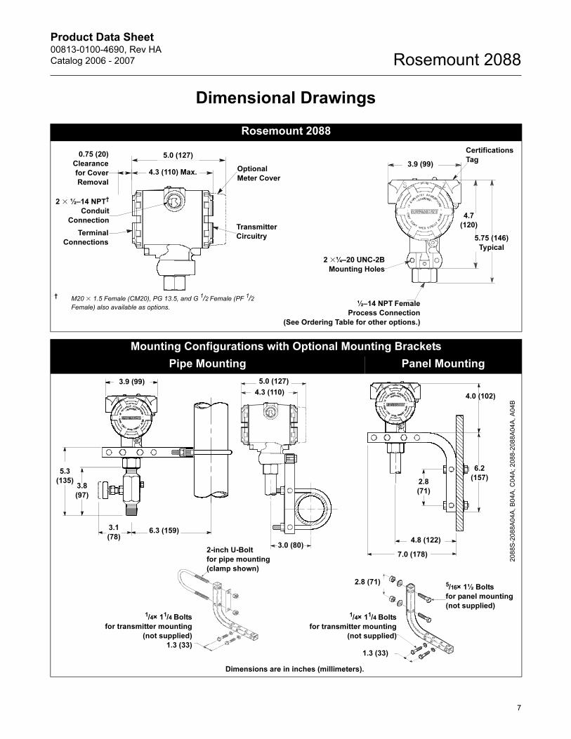
Dimensional Drawings
Rosemount 2088
Mounting Configurations with Optional Mounting Brackets
Pipe Mounting Panel Mounting
2 � ½–14 NPT†
Conduit
Connection
Terminal
Connections
5.0 (127)
Optional
Meter Cover
Transmitter
Circuitry
4.3 (110) Max.
0.75 (20)
Clearance
for Cover
Removal
Certifications
Tag
2 �¼–20 UNC-2B
Mounting Holes
½–14 NPT Female
Process Connection
(See Ordering Table for other options.)
3.9 (99)
5.75 (146)
Typical
4.7
(120)
† M20 � 1.5 Female (CM20), PG 13.5, and G 1/2 Female (PF 1/2 Female) also available as options.
6.3 (159)3.1
(78)
3.8
(97)
5.3
(135)
3.0 (80)
4.0 (102)
6.2
(157)2.8
(71)
4.8 (122)
7.0 (178)
2088S
-2088A
04A
, B
04A
, C
04A
; 2088-2
088A
04A
, A
04B
2-inch U-Bolt
for pipe mounting
(clamp shown)
1.3 (33)
2.8 (71) 5/16× 1½ Bolts
for panel mounting
(not supplied)1/4× 11/4 Bolts
for transmitter mounting
(not supplied)
Dimensions are in inches (millimeters).
3.9 (99) 5.0 (127)
4.3 (110)
1/4× 11/4 Bolts
for transmitter mounting
(not supplied)
1.3 (33)
7

Product Data Sheet00813-0100-4690, Rev HA
Catalog 2006 - 2007Rosemount 2088
Ordering Information
Model Product description
2088 Pressure Transmitter
Code Transmitter type
A Absolute
G Gage
Code Range Minimum span URL/Max.span/Sensor limit
1 0–30 psi (0–2.1 bar) 1.5 psi (103.0 mbar) 30 psi (2.1 bar)
2 0–150 psi (0–10.3 bar) 7.5 psi (517.0 mbar) 150 psi (10.3 bar)
3 0–800 psi (0–55.2 bar) 40 psi (2.8 bar) 800 psi (55.2 bar)
4 0–4,000 psi (0–275.8 bar) 200 psi (13.8 bar) 4000 psi (275.8 bar)
Code Output
S 4–20 mA dc/Digital HART® Protocol
N 1-5 V dc Low Power/ Digital HART protocol
Materials of Construction
Code Process connection Isolating diaphragm Oil fill
22(1) 316L SST 316L SST Silicone
33(1) Hastelloy C-276 Hastelloy C-276 Silicone
2B(1) 316L SST 316L SST Inert
Code Process connection
A ½–14 NPT Female
B DIN 16288 G ½ Male
C(2) RC ½ Female (PT ½ Female)
D(2) M20 � 1.5 Male (CM20 Male)
Code Conduit thread
1 ½–14 NPT
2 M20 � 1.5 Female (CM20)
3 PG 13.5
4 G ½ Female (PF ½ Female)
Code Options
Integral manifold
S5 Assembly to Rosemount 306 integral manifold (Use 1/2 - 14 NPT Female Process Connection code A)
Diaphragm seal assemblies
S1 Attachment of one diaphragm seal
Mounting brackets
B4 SST mounting bracket with SST Bolts
Special configuration (software)
C4(4) NAMUR alarm and saturation levels, high alarm
CN(4) NAMUR alarm and saturation levels, low alarm
C9(3) Software configuration
Special configuration (hardware)
C2 0.8 - 3.2 V dc output with HART protocol, Output code N only.
CR Compound range calibration capability
8

Product Data Sheet00813-0100-4690, Rev HA
Catalog 2006 - 2007 Rosemount 2088
00806-0100-4690EnglishRev. AA
Product Certifications
I1 (4) ATEX Intrinsically Safe
N1(4) ATEX Type n
ND(4) ATEX Combustible Dust
ED ATEX Flame-Proof
C6 CSA Explosion-Proof, Intrinsically Safe, and non-Incendive
K6(4) CSA and ATEX Explosion-proof and Intrinsically Safe (combination of C6, I1, and ED)
E4(4) JIS Flameproof (Available with Conduit Thread code 4 and with or without Digital Display codes M5 and M7)
E5 FM Approvals explosion-proof
I5 FM Approvals Intrinsically safe, non-incendive
K5 FM Approvals Explosion-proof, Intrinsically Safe, non-incendive (combination of E5 and I5)
KB FM Approvals and CSA Explosion-proof, Intrinsically Safe, non-incendive (combination of E5, I5, and C6)
KH(4) FM Approvals and ATEX Explosion-Proof and Intrinsically Safe (combination of E5, I5, and I1)
DW NSF drinking water approval (Requires Materials of Construction code 22 with Process Connection code A.)
Digital Display
M5 LCD display, scaled 0–100%
M7 LCD display, special configuration
Special procedures
P1 Hydrostatic testing
P2 Cleaning for special service
P8(5) 0.075% accuracy to 10:1 turndown
Special certifications
Q4 Calibration certificate
Q16 Surface finish certification for sanitary remote seals
Terminal blocks
T1 Transient protection (Available with Option codes E5, ED, I1, I5, N1, C6, and K5.
(1) Materials of Construction comply with recommendations per NACE MR0175/ISO 15156 for sour oil field production environments. Environmental limits apply to certain materials. Consult latest standard for details. Selected materials also conform to NACE MR0103 for sour refining environments.
(2) Not available with Hastelloy C-276, Materials of Construction code 33.
(3) A Configuration Data Sheet, see page 10, must be completed.
(4) Not available with low-power Output code N.
(5) Available with Output code S, stainless steel isolators, silicone fill, and for spans of 10 inH2O and greater.
9
Product Data Sheet00813-0100-4690, Rev HA
Catalog 2006 - 2007Rosemount 2088
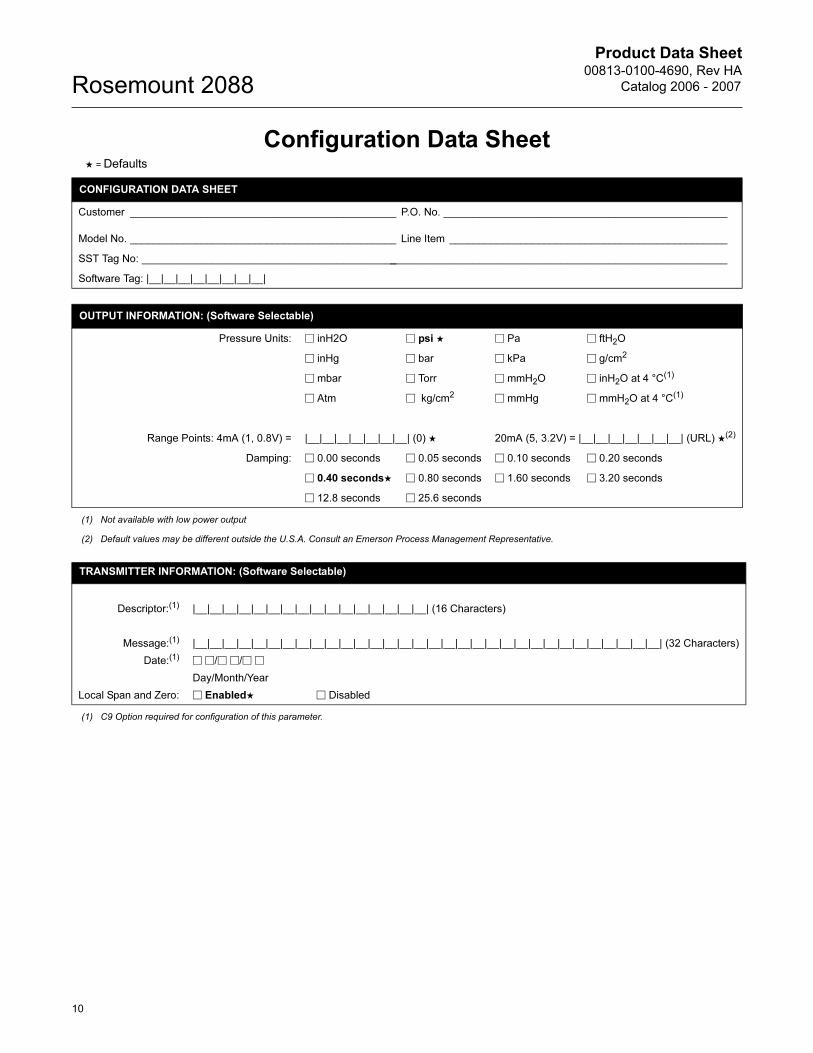
Configuration Data Sheet ★ = Defaults
CONFIGURATION DATA SHEET
Customer _____________________________________________ P.O. No. ________________________________________________
Model No. _____________________________________________ Line Item _______________________________________________
SST Tag No: ____________________________________________________________________________________________________
Software Tag: |__|__|__|__|__|__|__|__|
OUTPUT INFORMATION: (Software Selectable)
Pressure Units: � inH2O � psi ★ � Pa � ftH2O
� inHg � bar � kPa � g/cm2
� mbar � Torr � mmH2O � inH2O at 4 °C(1)
� Atm � kg/cm2 � mmHg � mmH2O at 4 °C(1)
Range Points: 4mA (1, 0.8V) = |__|__|__|__|__|__|__| (0) ★ 20mA (5, 3.2V) = |__|__|__|__|__|__|__| (URL) ★(2)
Damping: � 0.00 seconds � 0.05 seconds � 0.10 seconds � 0.20 seconds
� 0.40 seconds★ � 0.80 seconds � 1.60 seconds � 3.20 seconds
� 12.8 seconds � 25.6 seconds
(1) Not available with low power output
(2) Default values may be different outside the U.S.A. Consult an Emerson Process Management Representative.
TRANSMITTER INFORMATION: (Software Selectable)
Descriptor:(1) |__|__|__|__|__|__|__|__|__|__|__|__|__|__|__|__| (16 Characters)
Message:(1) |__|__|__|__|__|__|__|__|__|__|__|__|__|__|__|__|__|__|__|__|__|__|__|__|__|__|__|__|__|__|__|__| (32 Characters)
Date:(1) � �/� �/� �
Day/Month/Year
Local Span and Zero: � Enabled★ � Disabled
(1) C9 Option required for configuration of this parameter.
10
Product Data Sheet00813-0100-4690, Rev HA
Catalog 2006 - 2007 Rosemount 2088
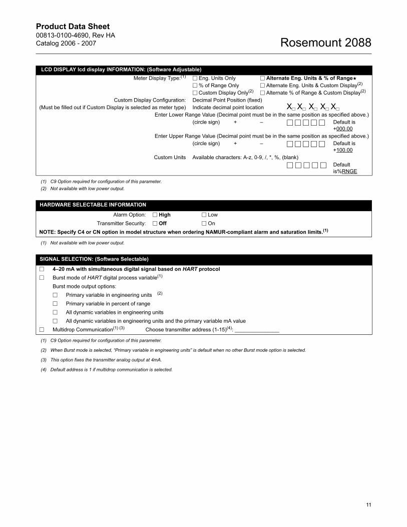
LCD DISPLAY lcd display INFORMATION: (Software Adjustable)
Meter Display Type:(1) � Eng. Units Only � Alternate Eng. Units & % of Range★
� % of Range Only � Alternate Eng. Units & Custom Display(2)
� Custom Display Only(2) � Alternate % of Range & Custom Display(2)
Custom Display Configuration: Decimal Point Position (fixed)
(Must be filled out if Custom Display is selected as meter type) Indicate decimal point location X� X� X� X� X�
Enter Lower Range Value (Decimal point must be in the same position as specified above.)
(circle sign) + – � � � � �
Default is
+000.00
Enter Upper Range Value (Decimal point must be in the same position as specified above.)
(circle sign) + – � � � � �
Default is
+100.00
Custom Units Available characters: A-z, 0-9, /, *, %, (blank)
� � � � � Default
is%RNGE
(1) C9 Option required for configuration of this parameter.
(2) Not available with low power output.
HARDWARE SELECTABLE INFORMATION
Alarm Option: � High � Low
Transmitter Security: � Off � On
NOTE: Specify C4 or CN option in model structure when ordering NAMUR-compliant alarm and saturation limits.(1)
(1) Not available with low power output.
SIGNAL SELECTION: (Software Selectable)
� 4–20 mA with simultaneous digital signal based on HART protocol
� Burst mode of HART digital process variable(1)
Burst mode output options:
� Primary variable in engineering units (2)
� Primary variable in percent of range
� All dynamic variables in engineering units
� All dynamic variables in engineering units and the primary variable mA value
� Multidrop Communication(1) (3) Choose transmitter address (1-15)(4): _______________
(1) C9 Option required for configuration of this parameter.
(2) When Burst mode is selected, “Primary variable in engineering units” is default when no other Burst mode option is selected.
(3) This option fixes the transmitter analog output at 4mA.
(4) Default address is 1 if multidrop communication is selected.
11
Product Data Sheet00813-0100-4690, Rev HA
Catalog 2006 - 2007Rosemount 2088
© 2006 Rosemount Inc. All rights reserved.
¢00813-0100-4690*¤
Rosemount, the Rosemount logotype, Annubar, ProPlate and Mass ProPlate are registered trademarks of Rosemount Inc.HART is a registered trademark of the HART Communications Foundation.Hastelloy and Hastelloy C-276 are registered trademarks of Haynes International.PlantWeb is a registered trademark of one of the Emerson Process Management group of companies.All other marks are the property of their respective owners.
Emerson Process Management
Emerson Process Management Heath PlaceBognor RegisWest Sussex PO22 9SHEnglandT 44 (0) 1243 863121F 44 (0) 1243 867554
Emerson Process Management Asia Pacific Private Limited1 Pandan CrescentSingapore 128461T (65) 6777 8211F (65) 6777 [email protected]
Rosemount Inc.8200 Market BoulevardChanhassen, MN 55317 USAT (U.S.) 1 800 999 9307T (International) (952) 906 8888F (952) 949 7001
www.rosemount.com
HP_Administrateur
serv