Product Data: LASERUSB Vibration Control System … vibracion/hoja...110 dBfs Random Dynamic Random:...
16
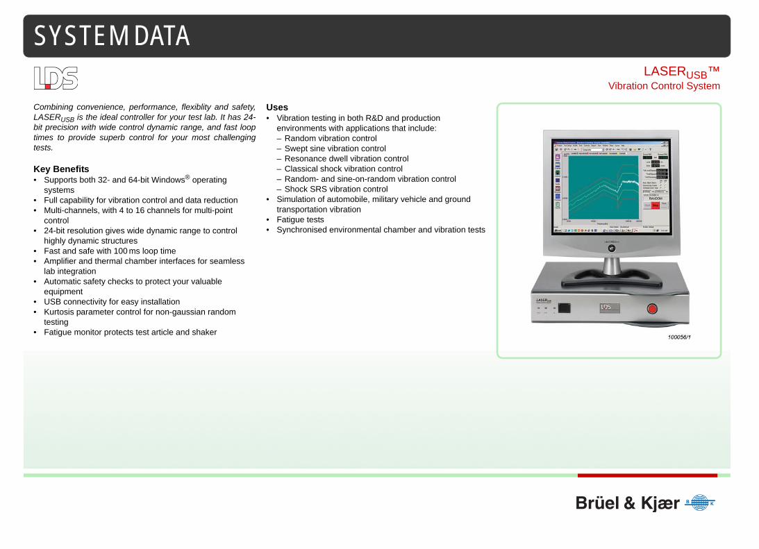
SYSTEM DATA LASER USB ™ Vibration Control System Combining convenience, performance, flexiblity and safety, LASER USB is the ideal controller for your test lab. It has 24- bit precision with wide control dynamic range, and fast loop times to provide superb control for your most challenging tests. Key Benefits • Supports both 32- and 64-bit Windows ® operating systems • Full capability for vibration control and data reduction • Multi-channels, with 4 to 16 channels for multi-point control • 24-bit resolution gives wide dynamic range to control highly dynamic structures • Fast and safe with 100 ms loop time • Amplifier and thermal chamber interfaces for seamless lab integration • Automatic safety checks to protect your valuable equipment • USB connectivity for easy installation • Kurtosis parameter control for non-gaussian random testing • Fatigue monitor protects test article and shaker Uses • Vibration testing in both R&D and production environments with applications that include: – Random vibration control – Swept sine vibration control – Resonance dwell vibration control – Classical shock vibration control – Random- and sine-on-random vibration control – Shock SRS vibration control • Simulation of automobile, military vehicle and ground transportation vibration • Fatigue tests • Synchronised environmental chamber and vibration tests
Transcript of Product Data: LASERUSB Vibration Control System … vibracion/hoja...110 dBfs Random Dynamic Random:...
SYSTEM DATA
LASERUSB™Vibration Control System
Combining convenience, performance, flexiblity and safety,LASERUSB is the ideal controller for your test lab. It has 24-bit precision with wide control dynamic range, and fast looptimes to provide superb control for your most challengingtests.
Key Benefits• Supports both 32- and 64-bit Windows® operating
systems• Full capability for vibration control and data reduction • Multi-channels, with 4 to 16 channels for multi-point
control • 24-bit resolution gives wide dynamic range to control
highly dynamic structures• Fast and safe with 100 ms loop time• Amplifier and thermal chamber interfaces for seamless
lab integration• Automatic safety checks to protect your valuable
equipment• USB connectivity for easy installation• Kurtosis parameter control for non-gaussian random
testing• Fatigue monitor protects test article and shaker
Uses• Vibration testing in both R&D and production
environments with applications that include: – Random vibration control– Swept sine vibration control– Resonance dwell vibration control– Classical shock vibration control– Random- and sine-on-random vibration control– Shock SRS vibration control
• Simulation of automobile, military vehicle and ground transportation vibration
• Fatigue tests• Synchronised environmental chamber and vibration tests

2
Specifications – LASERUSB Shaker Control System
Inputs Outputs
Control Loop
Safety
Hardware
General
Software
Regulatory Compliance
Analog Channels
4 standard, expandable to 16 simultaneous channels. Each can be controlled, monitored or disabled. All are differential inputs with 220 kΩ impedance
Electronics Differential amplifier, programmable gain amplifier, anti-aliasing filters, and 24-bit Analog-to-Digital Converter (ADC)
Filtering An analog filter plus a 160 dB/octave digital filter eliminates non-linear phase distortion and aliasing
Frequency Range
Up to 42 kHz analysis frequency (96000 samples per second)
Voltage Ranges
±10, 1, 0.1V
Input Coupling
DC or AC (analog circuitry)
Signal Conditioning
Voltage or CCLD* sensor power (4.7 mA, 23 Vpeak open circuit) and TEDS (Transducer Electronic Data Sheet)
* CCLD is Constant Current Line Drive, the generic name for a constant power supply for accelerometers with built-in electronics
Max. Input ±36 Vpeak without damageResolution 24-bitDynamic Range
120 dBfs, 110 dB minimum in FFT mode
Accuracy ±0.08 dB (1 kHz sine at full scale)Channel Match† Amplitude
† Channel match specification per 8-channel front-end
Within ±0.04 dB
Channel Match* Phase
Within ±0.1 degree to 2 kHz±0.5 degree to 20 kHz
Signal-to-noise
>100 dB (from DC to 1000 Hz measured with half full-scale sine wave)
Cross-talk < –110 dBTotal Harmonic Distortion
< –105 dBfs
Digital Input and Output
48 parallel lines for 5 V TTL signals. Used for remote start/stop/pause/continue and other functions such as close/open control loop, manual/auto schedule, and enable/disable aborts
Analog Channels
Drive and COLA (Constant Output Level Amplitude)/shock trigger outputs standard
Output Protection
Prevents output transient if power is switched off
Electronics 24-bit Digital-to-Analog Converter (DAC), anti-imaging filter, programmable gain attenuator, and shutdown circuitry.Single-ended output with 50 Ω impedance
Filtering A 160 dB/octave digital filter plus an analog filter elminates non-linear phase distortion and imaging
Frequency Range
Up to 22 kHz output frequency (48000 samples/sec)
Voltage Range ±10 Vpeak with adjustable attenuatorResolution 24-bitDynamic Range
110 dBfs
Random Dynamic
Random: 95 dBSine: 100 dB
Loop Time Random: 100 ms typical
Manual Abort Red button on front-end DSP box; software button on-screen; F4 key on keyboard
Pre-test Drive waveform validated against shaker performance table. Integrity checking of system and control loop
Test Open loop checks; loss of control signal checks; input overload checks; alarm and abort tolerance band checks; and rms abort limit checks.Graceful shutdown at user-specified rate
Front-end DSP Box
Control loop processing done independent of PC using dual DSP chips.Rear panel connectors for inputs and outputs, connection to PCI card, and 48 digital I/O lines.Front panel power switch, abort button and status LEDs
Input Channels
4 to 16 simultaneous inputs – extension to 12 to 16 inputs via channel expansion box option
Output Channels
2 analog outputs standard; drive and COLA /shock trigger
PC Requirements
USB 2.0 portMicrosoft® Windows® XP (32-bit), Windows 7(32- and 64-bit), or Windows 8 (64-bit) operating systemMicrosoft® WordWith more than 8 channels: 8 MB graphics card (recommended)
PC Expansion PC upgrades and peripheral additions do not delay or interrupt the control loop processing
AC Power 100 to 240 V, 50/60 Hz, auto-sensingPower Consumption
30 W
Dimensions Height: 8.9 cm (3.5 in)Width: 41.9 cm (16.5 in)Depth: 36.3 cm (14.3 in)
Weight 6 kg (13 lb)Temperature 5 to 55° C (41 to 132° F)Humidity 10% to 90% RH non-condensing
Architecture Distributed processing removes the PC from the control loop process. True multi-tasking allows the PC to deliver maximum graphics performance and responsiveness.Software provides on-line test status & management via text displays, software toggle buttons and displays of multiple time and/or frequency signals
Applications Random; Sine-on-Random; Random-on-Random; Sine- and Random-on-Random; Swept Sine; Resonance Search, Track and Dwell; Sine Oscillator; Classical Shock; Shock Response Spectrum; Transient Time History Control; Long Time History Control (for road simulation testing)
Features Online help; consistent management of user-defined engineering units; on-line graphics, one-click Word-based test reports with active data plots that can be rescaled, add cursors, etc.; project sequencing for automated testing to a mission profile
Compliance CE markingSafety EN/IEC 60950–1EMC FCC Part 15 (CFR 47) Class A, EN 61326 Class A,
CISPR 22 Class A

Specifications – Premier Random Vibration Control
Control Parameters
Reference ProfileEntered as a table of breakpoints, recalled stored profile or PSD, orimported ASCII or UFF file. Reference can be rescaled to a new rmsvalue.
Test ScheduleUser-defined sequence of events or ‘profiles’, that are automaticallyexecuted during test.
Safety Features
Fatigue MonitorThe Fatigue Monitor automatically stops the test if the inverse of thesystem transfer function (Hinverse) or selected transmissibility, orinput channel spectrum, exceeds specified abort limits. Hinversecould change because of fatigue in the test article, looseness in thefixture and mounting, or degradation of the shaker
Test ExecutionThe system performs pre-test checks, equalises the load and thenexecutes the schedule
Signal DisplaysUnlimited number of display windows in tile or cascade format withclick & drag zoom, user annotation, and cursors
On-line MathThis feature allows you to create customised signals. All signals arecalculated and displayed ‘live’ during testing. Operations includeaddition, subtraction, multiplication, division, and transmissibilitybetween PSDs for any two inputs or an input PSD and the control PSD.
Test ManagementControl panel toggle buttons and toolbar icons provide easy accessto test controls. Commonly used commands are also accessible viakeyboard function keys. Text messages and numerical readouts onthe control panel enhance test status monitoringl
Post-test DocumentationIcon for single-click generation of data plots and test reports,including setup parameter listings, test logs and formatted signalplots, within Microsoft® Word.
Frequency Range
0 to 10000 Hz* in seventeen ranges. Closed loop control up to 4000 Hz standard
* High Frequency Option extends to 10000 Hz
Resolution 110, 225, 450, 900, or 1800 lines
Δ F Resolution User-selectable, including 5 Hz and its multiples
Dynamic Range Up to 95 dB
Randomization Frequency domain phase randomization technique produces a true gaussian distribution
Loop Time Typically 100 ms
Variable Resolution
Provides enhanced low frequency control with up to 8-to-1 improvment in spectral resolution
Transfer Function
Measure during pre-test or, for quickest test start-up, recall a function from disk
DOF 2 to 1000
Control Strategy Single or multiple input channels combined by minimum, maximum, or weighted average. Drive clipping 2 to 6 sigma or disabled
Kurtosis Control An option that provides a better simulation of real world data and enhances fatigue testing. The system uses continuous feedback control to achieve a user-specified target K value
Limiting Any channel can be enabled as a Limit or Abort channel. Each Limit channel has a corresponding amplitude vs. frequency profile
Non-acceleration Control
Control using a force, velocity or displacement transducer; or control to angular acceleration
Breakpoints Unlimited combination of PSD levels and slopes (dB/octave) at user-defined frequencies
Abort/alarm High and low profile limits defined independently at each breakpoint in dB with respect to reference. RMS high and low limits calculated automatically from profiles or specified by user
Validation Tools Profile displayed and updated as it is created. Automatic listing of rms and peak acceleration, velocity and displacement values for profile. Profiles are validated against shaker parameters
Engineering Units English, SI, Metric, mixed; Linear or angular
Events Level & duration, timed pause, save signals, abort enable/disable, digital output trigger, and control loop close/open; logic for sequence & nested loops
Profile Sequencing
Flow diagram of blocks with each block defining a Profile and Schedule
Control Signal Automatic detection of input overload, open loop, and loss of control signal
Line-abort Trigger
Ratio of spectral lines allowed to exceed limits to total number of lines; From 0 to 1
Test Shutdown
Shutdown initiated by operator or software is performed gracefully at a user-specified rate
Abort Rate 1 to 120 dB/sec
Email Support Email message automatically sent on abort
Signals Hinverse, any transmissibility or input spectrum
Source Active signal or imported from disk file
Tolerances User-specified upper/ lower aborts and alarms in dB
Check Level From 10% to 100% of the full test level
Pre-test System performs safety checks then gradually increases the drive per the user-specified peak drive voltage (initial and maximum), response level goal, and ramp-up rate (slow or fast)
Automatic Mode
System executes the events specified in the schedule. If a Profile Sequence is defined, profile-schedule blocks in the flow diagram are sequentially executed. The reference is changed in one loop, eliminating the need to stop and restart the test to change the profile
Manual Mode User can override automatic mode to manage the test using manual commands
Window Format
Per window choice of single, dual, or four pane formats. Each pane can display single or multiple signals overlaid in either time or frequency. Independent choice of colour and texture for signals, grids, tick marks, labels, titles, etc.
Scale Format Linear or logarithmic scales for X and Y axes with automatic or manual scaling
Cursors Single or dual with X, Y, ΔX, ΔY, ΔRMS and Q value readouts; manual peak marks; automatic peak/valley detection and marks; harmonic and sideband cursors
Frequency Signals
Control, any input, transfer function (amplitude and phase), coherence, drive, profile, alarms, and aborts
Strip Chart Plots
Scrolling record (data point per frame) of input channel rms, max, min, or mean values
Oscilloscope Plots
Drive and input time histories
Buttons Start/stop, pause/continue, enable/disable, abort check, loop close/open, schedule clock on/off
Icons Test level set/increase/decrease, reset average, move to next event/profile, save signals
Status Displays
Control and demand rms acceleration, demand velocity and displacement, test %/dB/ratio level, peak drive volts, full level and total test time elapsed, time remaining, activity status, and a red alert message box
3

Specifications – Premier Swept Sine Vibration Control
Control Parameters
Reference ProfileEntered as a table of breakpoints for acceleration, velocity anddisplacement segments
Test ScheduleUser-defined sequence of events or ‘profiles’, that are automaticallyexecuted during test.
Safety Features
Test ExecutionThe system performs pre-test checks, equalises the load and thenexecutes the schedule
Test ManagementControl panel toggle buttons and toolbar icons provide easy accessto test controls. Commonly used commands are also accessible viakeyboard function keys. Text messages and numerical readouts onthe control panel enhance test status monitoringl
Signal DisplaysUnlimited number of display windows in tile or cascade format withclick & drag zoom, user annotation, and cursors
COLA Features
On-line MathThis feature allows you to create customised signals. All signals arecalculated and displayed ‘live’ during testing. Operations includeaddition, subtraction, multiplication, division, and transmissibilitybetween spectra for any two inputs or an input spectrum and thecontrol spectrum.
Post-test DocumentationIcon for single-click generation of data plots and test reports,including setup parameter listings, test logs and formatted signalplots, within Microsoft® Word.
Frequency Range
0.1 to 12000 HzUp to 4000 Hz standard; High Frequency option extends to 12000 Hz
Resolution 512, 1024 or 2048 points per sweep
Dynamic Range Up to 100 dB
Loop Time Typically 10 ms
Control Accuracy 1 dB through peak-notch with a Q of 50 at 1 octave/min., 8 control channels with 25% proportional tracking filters
Compression Rate
Adaptive or fixed 0.3 to 3000 dB/sec
Control Strategy Single, or multiple input channel combined by minimum, maximum or weighted average. Input amplitude estimated with peak, mean, rms or digital tracking filter on a per channel basis
Tracking Filter Proportional – Bandwidth: 7 to 100% of drive frequencyFixed – Bandwidth: 1 to 500 Hz
Sweep Rate Linear from 0 to 6000 Hz/min, or logarithmic from 0 to 100 oct./min
Limiting Any channel can be enabled as a Limit or Abort channel. Each Limit channel has a corresponding amplitude vs. frequency profile
Non-acceleration Control
Control using a force, velocity or displacement transducer; or control to angular acceleration
Breakpoints Unlimited combination of amplitudes (A, V or D) right and/or left constant A/V/D slopes at defined frequencies; automatic crossover calculations
Abort/alarm High and low profile limits defined independently at each breakpoint in dB with respect to reference
Validation Tools Profile displayed and updated as it is created. Automatic listing of peak acceleration, peak velocity and peak-to-peak displacement values for profile. Profiles are validated against shaker parameter table
Engineering Units English, SI, Metric, mixed; Linear or rotary
Events Sweeps (duration, sweep range and start frequency, sweep direction and sweep rates), dwells (frequency and cycle or time duration), level, timed pause, digital output trigger, enable/disable abort checking, control loop open/close, and save results; logic for sequence loop and nested loops
Profile Sequencing
Flow diagram of blocks with each block defining a Profile and Schedule
Control Signal Automatic detection of input overload, open loop, and loss of control signal
Abort Trigger Continuous time allowed abort limits: From 0 – 1 sec
Test Shutdown
Shutdown initiated by operator or software is performed gracefully at a user-specified rate
Abort Rate 1 to 120 dB/sec
Email Support Email message automatically sent on abort
Automatic Mode
System executes events specified in the schedule. If a Profile Sequence is defined, profile-schedule blocks in the flow diagram are sequentially executed
Manual Mode User can override automatic mode to manage the test using manual commands
Buttons Start/stop, pause/continue, enable/disable, abort check, loop close/open, schedule clock on/off
Icons Level adjustment, sweep up/down, sweep hold/release, set frequency, move to next event/profile, save signals
Status Displays
Frequency, control and demand peak acceleration, demand velocity and displacement, test %/dB/ratio level, peak drive volts, full level and total test time elapsed, time remaining, activity status, and a red alert message box
Window Format
Per window choice of single, dual, or four pane formats. Each pane can display single or multiple signals overlaid in either time or frequency. Independent choice of colour and texture for signals, grids, tick marks, labels, titles, etc.
Scale Format Linear or logarithmic scales for X and Y axes with automatic or manual scaling Dimension: A, V or D
Cursors Single or dual with X, Y, ΔX, ΔY, ΔRMS and Q value readouts; manual peak marks; automatic peak/valley detection and marks; harmonic and sideband cursors
Frequency Signals
Control, any input, transfer function (amplitude and phase), coherence, drive, profile, alarms, and aborts
Strip Chart Plots
Scrolling record of peak value versus time for the control signal or any input signal; frequency versus time
Oscilloscope Plots
Input time histories
Resonance Search
Table display of resonance frequencies and Q factors
Constant Amplitude
Sine output with programmable amplitude from 0.1 to 10 V
DC Proportional
Varying DC output proportional to frequency; programmable frequency with linear or log interpolation
4

Specifications – Premier Classical Shock Transient Control
Control Parameters
Reference Waveform Convenient pulse selection from a waveform library. User-specifiedduration and peak acceleration.
Test Schedule User creates a schedule of events to perform during the test.Looping and nested looping logic speed and simplify programming.
Safety Features User creates a schedule of events to perform during the test.Looping and nested looping logic speed and simplify programming.
Test Execution The system performs pre-test checks, equalises the load, and thenexecutes the schedule.
Test ManagementControl panel toggle buttons and toolbar icons provide easy accessto test controls. Commonly used commands are also accessible viakeyboard function keys. Text messages and numerical readouts onthe control panel enhance test status monitoringl
Signal Displays Unlimited number of display windows in tile or cascade format withclick & drag zoom, user annotation, and cursors.
Post-test Documentation Icon for single-click generation of data plots and test reports,including setup parameter listings, test logs, and formatted signalplots, within Microsoft® Word.
Frequency Range
0 to 22000 Hz
Frame Size 128 to 16384 points or automatically optimised. Linear filter design minimises distortion and preserves the true waveform shape
Transfer Function
Measure during pre-test or, for quickest test start-up, recall a function from disk
Averaging User-specified coefficient from 1 to 500
Filtering User specifies cut-off frequency for low-pass filtering applied to the reference waveform, drive, and all input channels
Pulse Delay User-specified delay between pulses from 0 to 1000 sec
Pulse Types Half-sine, haversine, initial and terminal peak sawtooth, triangle, rectangle and trapezoid
Pulse Duration From 0.5 to 3000 ms
Compensation Pre-and post-pulse, post-pulse only, or pre-pulse only. Single- or double-sided for minimum acceleration and full use of shaker stroke. Choice of displacement optimum, half-sine, rectangular, rounded rectangular, or triangular compensation pulses. Pre-pulse and post-pulse amplitudes definable in percentage of reference peak acceleration
Abort Limits Set to MIL–STD 810 guidelines or customised by user in percentage of reference waveform amplitude and percentage of pre-pulse and post-pulse amplitudes
Validation Tools
Waveform displayed and updated as it is created. Automatic display of profile acceleration, velocity, and displacement waveforms together with shaker limits. Shock profile is validated against shaker parameter table
Engineering Units
English, SI, Metric, mixed
Events Level and number of pulses, digital output trigger, abort enable/disable, and loop open/close, save results, pause, invert pulse
Control Signal Automatic detection of input overload, open loop, and loss of control signal
Point-abort Trigger
Allowable ratio of points exceeding abort limits to total number points in a frame: 0 to 1
Test Shutdown
Shutdown initiated by operator or software is performed gracefully
Email Support Email message automatically sent on abort
Pre-test System performs safety checks then gradually increases the drive per the user-specified peak drive voltage (initial and maximum), response level goal, and ramp-up rate (slow or fast)
Automatic Mode
System sequentially executes each event in the schedule
Manual Mode User can override automatic mode to manage the test using manual commands
Buttons Start/stop, pause/continue, enable/disable, abort check, loop close/open, schedule clock on/off
Icons Test level set/increase/decrease, ouput a single pulse, move to next event/profile, save signals
Status Displays
Control and demand peak acceleration, demand velocity and displacement, test %/dB/ratio level, peak drive volts, full level and total test time elapsed, time remaining, activity status, and a red alert message box
Window Format
Per window choice of single, dual, or four pane formats. Each pane can display single or multiple signals overlaid in either time or frequency. Independent choice of colour and texture for signals, grids, tick marks, labels, titles, etc.
Scale Format Linear or logarithmic scales for X and Y axes with automatic or manual scaling. Dimension: A, V or D
Cursors Single or dual with X, Y, ΔX, ΔY, ΔRMS and Q value readouts; manual peak marks; automatic peak/valley detection and marks; harmonic and sideband cursors
Time Signals Control, drive, any input, profile, aborts, composite (control, profile, aborts)
Frequency Signals
Control
Strip Chart Plots
Scrolling record (data point per buffer) of any input channel’s rms, max, min, or mean
SRS Analysis Up to 14 octave range (maxi-max, negative maximum, and positive maximum). User specifies high and low frequency, centre frequency, damping ratio or Q value, and resolution (1/1, 1/3, 1/6, 1/12, 1/24, or 1/48)
5

Specifications – Sine-on-Random (SoR) Vibration Control
Test Setup and ControlSoR includes all of the features of the Random Vibration Controlpackage with one exception – the maximum frequency is limited to4000 Hz (5500 Hz with the High Frequency option).
Set up of a SoR broadband Power Spectral Density (PSD) profile isthe same as in the Random package. Up to 20 sine tones areadded. Automatic on/off switching (at arbitrary intervals) of each ofthe sine tones, or even the broadband random, can be set in theschedule.
Broadband Control TechniqueThe broadband control process is the same as that used in theRandom package. The PSDs for the drive and control channels arecalculated on a per frame basis and used to continuously updatethe control loop transfer function. The broadband random drivesignal has a true gaussian distribution.
Sine Tone Control TechniqueUp to 12 tones can be controlled simultaneously. An individualphase-locked tracking filter is applied to each sine tone toaccurately extract its amplitude from the control feedback signal.The sine tone portions of the drive signal are generated digitallywith updates to amplitude and frequency made on a per point basisor at zero-crossings.
A high precision waveform generator creates pure sine tones withextremely low amplitude distortion. The Total Harmonic Distortion(THD) of each sine tone is less than –90 dB. Tone frequencies arechanged with anlaog-like smoothness. The tone sweepcharacteristics are not linked to the broadband random spectralresolution or the frame acquisition time.
Special Features
Special DisplaysSoR provides the following special data displays:
Sine Tone Characteristics
Sine-on-SineThe broadband random may be totally suppressed allowing multi-sine excitation with up to 20 sine tones simultaneously
Test Management SoR includes all of the automatic and manual test controls that areincluded in the Random software package, with the addition of acontrol panel that allows the user to switch on/off individual sinetones or the broadband random
Validation Tools
Automatic listing of acceleration, velocity and displacement values for the broadband, tones and overall profile. The sum of the rms values of all active components (sine tones and broadband random) is used to calculate the overall expected peak vibration levels. The peak A/V/D levels are automatically validated against the shaker limits prior to starting a test and before implementing any manual mode changes during testing
RMS Limits High/low rms alarm/abort limits can be automatically calculated based on profiles or entered by the user
Tone Tracks Acceleration versus frequency online displays for all sweeping tones
Sweep Envelope
Amplitude versus frequency sweep envelope for tones, provides pre-test validation of the setup
Number Up to 20 tones
Target Amplitude
Fixed acceleration or amplitude versus frequency profile table
Profile Breakpoints
Unlimited combination of amplitudes (A, V or D) and right and/or left constant A/V/D slopes at defined frequencies
High Abort/alarm
Limits specified in dB with respect to the target amplitude
Frequency Range
High, low, and initial frequency in Hz (all with a resolution as fine as .000001 Hz)
Initial Direction
Increasing or decreasing from the initial frequency
Sweep Mode Linear or logarithmic specified as rate or time
Sweep Rate Linear at 0 to 1000 Hz/min, or logarithmic at 0 to 20 oct./min
Sweep Time User-defined in minutes/sweep
Ramping Rate 0 to 200 dB/sec (the amplitude changes between 0 and the target at this rate after the tone is switched on/off)
Burst On and Off
Independent time on time off with resolution of 0.001 sec
Harmonic Mode
Sets tones no. 2, 3, 4,... to be integer multiples of sine tone no. 1’s frequency parameters
Automatic Mode
While creating the test schedule, the user arranges events using looping and nested looping logic similar to creating a schedule in Random. In SoR, the control panel can be repeatedly inserted as an event to switch on/off individual sine tones or the broadband random at any time. One typical application of this feature is to delay the start time of the sine tones until after the random has reached full level.This flexible implementation of the schedule allows users to write their own script for the test
Manual Mode During testing, the user can use the control panel to activate or deactivate any of the components at any time. The software will validate the overall required rms value against shaker limits before implementing any changes
6

Specifications – Random-on-Random (RoR) Vibration Control
Test Setup and ControlRoR includes all of the features of the Random Vibration Controlpackage with one exception – the maximum frequency is limited to4000 Hz (5500 Hz with the High Frequency option).
Set up of a RoR broadband Power Spectral Density (PSD) profile isthe same as in the Random package. Up to 12 narrowbands areadded. Automatic on/off switching (at arbitrary intervals) of each ofthe narrowbands, or even the broadband random, can be set in theschedule.
Broadband Control TechniqueThe broadband control process is the same as that used in theRandom package. The PSDs for the drive and control channels arecalculated on a per frame basis and used to continuously updatethe control loop transfer function.
Narrowband Control TechniqueThe reference profile is updated on a per frame basis. The totaldrive signal, made up of the broadband random plus the randomnarrowbands, has a true gaussian distribution.
Special DisplaysRoR provides the following special data displays:
Safety FeaturesAutomated and interactive test modes reduce test time and allowtailored testing.
Narrowband Characteristics Test Management RoR includes all of the automatic and manual test controls that areincluded in the Random software package, with the addition of acontrol panel that allows the user to switch on/off individualnarrowbands or the broadband random
Sweep Envelope
PSD amplitude versus frequency sweep envelope for narrowbands, provides pre-test validation of the setup
Validation Tools
Automatic listing of acceleration, velocity and displacement values for the broadband, narrowbands and overall profiles The sum of the rms values of all active components (narrowbands and/or random vibration) is used to calculate the overall expected peak vibration levels. The peak A/V/D levels are automatically validated against the shaker limits prior to starting a test and before implementing any manual mode changes during testing
RMS Limits High/low rms alarm/abort limits can be automatically calculated based on profiles or entered by the user
Number Up to 12 narrowbands
Target Amplitude
Acceleration PSD (for example, G/Hz, or (min/sec)/Hz, etc.)
Profile Breakpoints
Unlimited combination of PSD levels with right and left slopes (dB/octave) at user-defined frequencies
Narrowband Width
Frequency width specified in Hz
High Abort/alarm
Limits specified in dB with respect to the target amplitude
Frequency Range
High, low, and initial frequency in Hz (specified for the centre frequency of the narrowband)
Initial Direction
Increasing or decreasing from the initial frequency
Sweep Mode Linear or logarithmic specified as rate or time
Sweep Rate Linear at 0 to 500 Hz/min, or logarithmic at 0 to 10 oct./min
Sweep Time User-defined in hours:minutes:seconds
Ramping Rate 0 to 60 dB/sec (the amplitude changes between 0 and the target at this rate after the narrowband is switched on/off)
Harmonic Mode
Sets narrowbands no. 2, 3, 4,... to be integer multiples of narrowband no. 1’s frequency parameters
Profile Composition
Sum of narrowbands and broadbands or maximum between narrowbands and broadband
Automatic Mode
While creating the test schedule, the user arranges events using looping and nested looping logic similar to creating a schedule in Random. In RoR, the control panel can be repeatedly inserted as an event to switch on/off individual narrowbands or the broadband random at any time. One typical application of this feature is to delay the start time of the narrowbands until after the random has reached full level.This flexible implementation of the schedule allows users to write their own script for the test
Manual Mode During testing, the user can use the control panel to activate or deactivate any of the components at any time. The software will validate the overall required rms value against shaker limits before implementing any changes
7

Specifications – Sine- and Random-on-Random (SRoR) Vibration Control
This add-on module for the SoR and RoR Vibration Controlsoftware packages, allows for the user to create a vibrationenvironment by combining fixed or sweeping sine tones and fixedand sweeping random narrowbands with broadband randomvibration.
The ultimate in closed loop control applications, SRoR enables theuser to simulate the most demanding environments in their test lab.Similar to SoR and RoR, the user can individually activate anddeactivate any component (sine tone, narrowband, or broadband)of the environment.
SRoR is very easy to set up and run, and is unique in that it usesthe power of 60 MHz DSPs (with floating point math) to execute anadvanced phase-locked tracking filter technique simultaneouslyoneach of the independent sine tones.
For gunfire simulations, it allows for exceptionally fine control ofburst time on/off. Abrupt changes in level, when switching the sinetones or narrowbands on and off, are managed with a user-definedramping rate.
Test Setup and ControlSRoR includes all of the features of the Random, SoR and RoRVibration Control packages with one exception – the maximumfrequency is limited to 4000 Hz (5500 Hz with the High Frequencyoption).
Set up of a SRoR broadband Power Spectral Density (PSD) profileis the same as in the Random package. Up to 12 sine tones and 12narrowbands are added. Automatic on/off switching (at arbitraryintervals) of each of the sine tones and narrowbands, or even thebroadband random, can be set in the schedule. During testing, thesystem simultaneously controls the sine tones, randomnarrowbands and broadband random.
Broadband Random Control TechniqueSame as for the Random Vibration Control package.
Sine Tone Control TechniqueSame as for the SoR Vibration Control package.
Sine Tone CharacteristicsSame as for the SoR Vibration Control package.
Narrowband Control TechniqueSame as for the RoR Vibration Control package.
Narrowband CharacteristicsSame as for the RoR Vibration Control package.
Test ManagementSame as for the SoR and RoR Vibration Control packages.
Safety FeaturesSame as for the SoR and RoR Vibration Control packages.
8

Specifications – Resonance Search, Track and Dwell (RSTD) Vibration Control
Test Setup and ManagementAll of the features of Swept Sine Vibration Control software areincluded in the RSTD package. Users can follow familiarprocedures for quick test setup. In Schedule, the user defines aSearch Event by frequency range, sweep rate, and minimum Q andamplitude for resonance detection.
Schedule also allows easy definition of a Dwell Event by selectingeither a frequency locked dwell or tracked dwell at the resonancesin the Dwell List generated during the Search Event.
During the resonance search all of the control buttons, icons andstatus displays are available as in the Swept Sine package.
Resonance Search Resonance search creates a Dwell List from a measuredtransmissibility function using specified detection criteria
Resonance Dwell and Tracked Dwell Automated and interactive test modes reduce test time and allowtailored testing
Signal Displays RSTD offers all of the flexible window displays and plot attributeselections available in the Swept Sine Control package.
RSTD also provides a special four-pane window that updatesduring search and dwell operations:
Special displays for monitoring resonance dwells include:
Post-test Documentation Documentation and reports of both setup parameters and signalsproduced through Microsoft® Word as printed media or saved fileson disk
Transmissibility Measurement between any pair of inputs or an input and the control signal
Search Range User-selected start and end frequencies within the frequency range defined by the reference profile
Sweep Rate Default to the sweep rate for the reference profile or user-specified special sweep rate
Detection Criteria
Identification of resonances based on Q and transmissibility amplitude thresholds
Test Modes Choice of three modes: (1) Search and dwell as each resonance is detected during the sweep; (2) Search then automatically dwell using the generated Dwell List; (3) Search, pause for user review and editing of the Dwell List, then automatically dwell using the edited Dwell List
Dwell Modes Fixed frequency or tracked resonance dwell. Tracked dwell adjusts the drive frequency to track the resonance as its frequency changes during dwelling
Dwell Duration Time or cycles using true cycle counting
Drift Criteria Programmed end to resonance track on a frequency drift exceeding a specified percentage of the initial resonant frequency, a specified shift in frequency over a specified time interval, or a specified change in amplitude ratio
Search Log Provides a time-stamped list of all activities including search start/end, resonance frequencies found, and resonance tracking status
Dwell List Shows the frequency, amplitude, phase, Q, and elapsed time for each resonance found. Interactive editing via Add and Remove buttons: Add inserts a resonant frequency value, Remove deletes resonances based on screening by list entry number, Q, or amplitude
Amplitude Plot
Plot of transmissibility magnitude versus frequency
Phase Plot Plot of transmissibility phase angle versus frequency.
Dwell Histories
Control acceleration versus time and drive frequency versus time
Frequency Signals
Control acceleration, derived velocity, or derived displacement versus frequency
Run Log Time and test frequency (Hz) stamped list of all test operations including test start/end, schedule actions, operator commands, and error or abort conditions
Search Log Time-stamped list of all resonance search and dwell operations including search start/end, resonance frequencies found, and dwell start/end
Resonance List
Tabulated list of resonance frequencies and corresponding amplitude, phase, Q, dwell status, and dwell duration
Data Plots Transmissibility function, control acceleration versus time, drive frequency versus time; saved either automatically or manually
9

Specifications – Shock Response Spectrum (SRS) Transient Control
Test SetupAll of the features of the Classical Shock Transient Control packageare included in SRS. Users will recognise the same implementationof Schedule, Test Execution, Test Management and SignalDisplays.
Preparing the reference waveform is a three-step process:1. The user specifies a Required Response Spectrum (RRS).2. The software uses independent wavelets to synthesise a
waveform matching the energy content of the RRS.3. The software compensates the waveform to ensure zero final 6
matching the energy content of the RRS.
Required Response Spectrum (RRS)The RRS is an acceleration versus frequency spectrum that can bedefined with as few as two breakpoints. The user enters a table ofbreakpoints and high/low abort limits, then selects parameters todivide the RRS into discrete Nth-octave bands centred on thereference frequency.
Waveform SynthesisThe software uses the wavelet parameters and synthesisparameters to automatically generate wavelets for each of the Nth-octave bands. The wavelets are combined (synthesised) to producean initial estimate of the composite transient waveform. The SRS ofthat waveform is calculated and overlaid on the RRS.
If the initial estimate has converged to the RRS, the user can eitheraccept it and move on to Compensation, or modify the synthesisparameters and/or individual wavelet parameters, then iterate toachieve the desired level of convergence.
Wavelet Parameters
Waveform Compensation
Test Execution The system performs pre-test checks, equalises the load, and thenexecutes the schedule.
Control TechniqueThe control loop transfer function is updated after each pulse.Following each pulse, the control SRS abort limits are checked.
Breakpoints Unlimited combination of target acceleration amplitude with right and/or left slopes (dB/octave) up to 22000 Hz
Abort Limits Specified in dB with respect to the target amplitude
RRS Parameters
Low, high and reference frequency; damping ratio (%) or Q; Nth-octave bands (1/1, 1/3, 1/6, 1/12, 1/24, 1/48)
Wavelet Types
Half-cycle sinusoids with sine, exponential (gives damped sine), rectangular or Hann window
Waveform Criterion
Pyro-shock, minimum acceleration, or specified time duration (ms)
Listing Per wavelet list of frequency (Hz), RRS value (acceleration), synthesised amplitude (acceleration)
Definition Number of half-cycles, delay (ms) and wavelet amplitude (acceleration)
Analysis Type Maxi-max, positive maximum and negative maximum
Damping Percent of critical damping or Q value
Resolution Reduction Factor
Allows the user to automatically deactivate every Nth wavelet, N = 2 to 48
Error Display Numeric display of rms difference between the RRS and synthesised spectrum
Compensation High-pass filtering or DC removal to bring the final acceleration, velocity and displacement to zero
Pre-test System performs safety checks then gradually increases the drive per the user-specified peak drive voltage (initial and maximum), response level goal, and ramp-up rate (slow or fast)
Automatic Mode
System sequentially executes each event in the schedule
Manual Mode User can override automatic mode to manage the test using manual commands
Signal Displays
During testing, the user can display measured waveforms as acceleration, velocity and/or displacement; standard SRS or A/V/D nomograph SRS
Frame Size Automatically optimised (up to 16384 points) for the reference waveform. Linear filters minimise distortion and preserves the true waveform shape
Sampling Rate
Up to 48000 samples per second
Transfer Function
Measure during pre-test or, for quickest test start-up, recall a function from disk
Averaging User-specified coefficient from 1 to 500
Filtering User specifies cut-off frequency for low-pass filtering applied to the reference waveform, drive, and all input channels
SRS Analysis Up to 14 octave range using maxi-max, negative maximum, and positive maximum analysis techniques. User specifies high and low frequency, reference frequency, damping ratio or Q value, and resolution (1/1, 1/3, 1/6, 1/12, 1/24, 1/48)
Line-abort Trigger
Allowable ratio of lines exceeding abort limits to total number of lines in the RRS: 0 to 1
Pulse Delay User-specified delay between pulses from 0 to 1000 sec
10

Specifications – Transient Time History (TTH) Control
Profile ImportWaveforms are imported by specifying the source file format andthen using Browse to locate a file and import a profile. Digitalresampling adjusts the data’s sample interval (time step betweendata points) to match standard system sampling rates.
Profile Editing and CompensationSelect and apply editing techniques to modify the profile whileviewing the acceleration, velocity and displacement waveforms.
Multiple compensation techniques ensure initial and final conditionsof zero acceleration, velocity and displacement.
Control TechniqueControl process is identical to the Classical Shock Transient Controlsoftware. The spectra for the drive and control channels arecalculated per data frame and used to adjust the control looptransfer function.
Transfer Function EqualisationTTH provides flexible and accurate control loop transfer functionequalisation, with six methods offered:
Test ManagementTTH includes all of the automatic and manual test controls that areincluded in the Classical Shock package. Any or all of the inputchannels are available to display as acceleration, velocity ordisplacement waveforms during testing or for post-test analysis.
During testing, a special stip chart scrolling display is standard onall time domain input signals. This display gives fast visualvalidation even for very low frequency tests.
Over-test ProtectionWaveforms are imported by specifying the source file format andthen using Browse to locate a file and import a profile. Digitalresampling adjusts the data’s sample interval (time step betweendata points) to match standard system sampling rates.
File Formats ASCII delimited format (tab, comma or space) using Y values or XY data pairs, ASCII UFF, MTS® RPC III and binary format
Digital Resampling
From 48000 samples per second down to 20 samples per second in 24 stages
Frame Size 256, 512, 1024, 2048, 4096, 8192 or 16384 samples
Pre-stored Profiles
Bellcore Z1 and Z2, Bellcore Z3, Bellcore Z4, sine, chirp, burst sine and other waveforms
Rescale Adjust the reference waveform’s magnitude or polarity by applying a scale factor to each data point
Fill-in Select a range of data points and specify a new Y value for all of those data points
Taper End Points
Applies a Hann window over a specified percentage of the leading and trailing parts of the waveform
Compensation Pre- and post-pulses, brick wall high-pass filter, high-pass filter, DC removal, or disabled
Quick Start Method
Browse through disk files, recall a stored transfer function and skip the pre-test
Closed Loop Method
The system outputs a drive waveform and measures the transfer function. A new drive waveform is computed and the process repeated until the control response matches the profile at a specified goal level
Open Loop Methods
1. Profile(t): Uses the profile waveform as the drive output
2. Random White Noise: System creates the drive waveform from a flat broadband random profile
3. Shaped Random Noise: System uses the spectrum shape of Profile(t) to create a shaped random output
The system outputs a drive waveform and measures the transfer function. This process is repeated several times with the exact same drive waveform output every time. The peak drive voltage and the number of outputs are user-specified
Validation Tools
Waveform displayed and updated as it is created, imported or edited. Automatic display of profile acceleration, velocity and displacement waveforms together with shaker limits. Profile demands are validated against the shaker parameters
Automatic or Manual Abort
High and low abort limits can be entered directly by the user. Continuous point-abort checking is performed during testing. This allows aborts during a test rather than only at the end of an entire data frame (critical for long duration low-frequency events)
11

Specifications – Long Time History (LTH) Road Simulation Control
Profile ImportWaveforms are imported by specifying the source file format andthen using Browse to locate a file and import a profile. Digitalresampling adjusts the data’s sample interval (time step betweendata points) to match standard system sampling rates.
Profile Editing Select and apply editing techniques to modify the profile whileviewing the acceleration, velocity and displacement waveforms.
Profile
Test SchedulePre-programmed schedule of test events including test level,number of output repetitions and save results.
Over-test Protection
Initial Equalisation
Drive GenerationAfter the initial transfer function has been determined, a test can bestarted immediately. The drive signal is output with constantadjustments as the test progresses. A unique overlappedconvolution algorithm ensures a continuous drive signal withsmooth transitions between output frames.
On-line ControlThe transfer function is continuously updated during the test at auser-specified rate. This technique adjusts for non-linear effectsand changing load dynamics to deliver high accuracy without theneed for multiple pre-test iterations.
Signal Displays Unlimited number of display windows in tile or cascade format withclick & drag zoom, user annotation, and cursors.
Post-test Documentation Icon for single-click generation of data plots and test reports,including setup parameter listings, test logs, and formatted signalplots, within Microsoft® Word.
File Formats ASCII delimited format (tab, comma or space) using Y values or XY values, ASCII UFF, MTS® RPC III and binary format
Digital Resampling
From 20 to 12000 samples per second in 20 stages
Pre-stored Profiles
Band-limited random, white noise, sine and chirp
Build Waveform
Replace, insert or append a waveform. A splice utility ensures waveform continuity between adjoining waveform segments
Rescale Adjust the reference waveform’s magnitude or polarity by applying a scale factor to each data point
Compensation Acceleration DC removal, velocity, DC removal, high-pass filter, low-pass filter, decimation, none
Shaped Random
Random profile with spectrum shaped specified by breakpoint table or imported PSD; user-specified kurtosis and skew
Single Profile One profile with associated test schedule
Multiple Profiles
Unlimited profiles each with independently specified number of repetitions and level
Validation Tools
Waveform displayed and validated against the shaker parameters
Automatic or Manual Abort
Continuous point-abort checking is performed during testing. This allows aborts during a test rather than only at the end of an entire output data frame
Quick Start Method
Browse through disk files, recall a stored transfer function and skip the pre-test
Shaped Random Method
A random noise drive signal, based on a defined PSD profile, is output and the transfer function measured using a closed loop method. The PSD profile is entered as an unlimited combination of PSD levels with right and/or left slope (dB/octave) at user-defined frequencies. Or, the PSD of the actual waveform may be used. The PSD profile may also be defined by a measured PSD, or imported ASCII or UFF file. The user can, in addition, rescale the PSD profile to a new rms value.
Window Format
Per window choice of single, dual, or four pane formats. Each pane can display single or multiple signals overlaid. Independent choice of colour and texture for signals, grids, tick marks, labels, titles, etc.
Scale Format Linear or logarithmic scales for X and Y axes with automatic or manual scaling. Dimension: A, V or D
Cursors Single or dual with X, Y, ΔX, ΔY, ΔRMS and Q value readouts; manual peak marks; automatic peak/valley detection and marks; harmonic and sideband cursors
Time Signals Control, profile, any input, aborts, composite (control, profile, aborts) and drive; scrolling input histories
Frequency Signals
Control, profile and drive
12

Specifications – Value Random, Swept Sine and Classical Shock Software
Value Vibration Control software provide an economical way to configure a LASERUSB Vibration Controller for random, sine and classical shock testing. Easy-to-use software, together with extensive automationfeatures such as on-line transmissibility functions, also make the Value applications suitable for research and product development testing.
As your test needs grow, you can conveniently enhance the capabilities of your vibration controller by upgrading from Value packages to Premier packages. The upgrade is simple and no additional hardware isrequired to make the change. Plus, all of your existing Value test project files are fully compatible with the upgraded Premier packages.
Value Random Vibration Control Value Swept Sine Vibration Control Value Classical Shock Transient Control
Reference ProfileBreakpoint table with unlimited combination of PSD levels with right and/or left slope (dB/octave) at user-defined frequencies
Frequency Range 0 to 2400 Hz in eight ranges; 4000 Hz optional
Resolution 110, 225 or 450 spectral lines; 800 lines optional
Dynamic Range Up to 95 dB
RandomisationFrequency domain phase randomisation technique produces a true gaussian distribution
Loop Time Typically 100 ms
Transfer FunctionMeasure during pre-test or for quickest test start-up, recall a function from disk
DOF 2 to 1000
Control Accuracy 1 dB at 99% confidence with 200 DOF
Number of Inputs 4 to 8
Control StrategyControl to any single input channel; multiple channel option
Drive Clipping 3 to 6 sigma or disabled
Reference ProfileUnlimited combination of amplitudes (A, V or D) and right/left constant A/V/D slopes at defined frequencies
Frequency Range0.1 Hz to 2400 Hz; optional 4000 and 12000 Hz ranges
Dynamic Range Up to 100 dB
Loop Time Typically 10 ms
Control Accuracy1 dB through a peak-notch with a Q of 50, at 1 octave/min
Compression Rate Adaptive or fixed 0.3 to 3000 dB/sec
Number of Inputs 4 to 8
Control Strategy
Control to any single input channel; multiple channel option. Peak, mean or rms input channel amplitude processing. Digital tracking filters optional
Sweep RateLinear from 0 to 6000 Hz/min or logarithmic from 0 to 100 octaves/min
Drive Resolution As fine as 0.000001 Hz
Sine DwellUser-specified dwell frequency with duration specified in cycles or time
Pulse TypesHalf-sine, Haversine, initial and terminal peak sawtooth, triangle, rectangle and trapezoid
Compensation
Pre- and post-pulse, post-pulse only, or pre-pulse only. Single- or double-sided for minimum acceleration and full use of shaker stroke
Frequency Range 0 to 22000 Hz
Frame Size128 to 16384 points or automatically optimised. Linear filter design minimises distortion and preserves the true waveform shape
Number of Inputs 4 to 8
Transfer FunctionMeasure during pre-test or for quickest test start-up, recall a function from disk
Averaging User-specified coefficient from 1 to 500
FilteringUser-specified cut-off frequency for low-pass filtering applied to the reference waveform, drive and all input channels
Pulse Delay User-specified from 0 sec. to unlimited
13
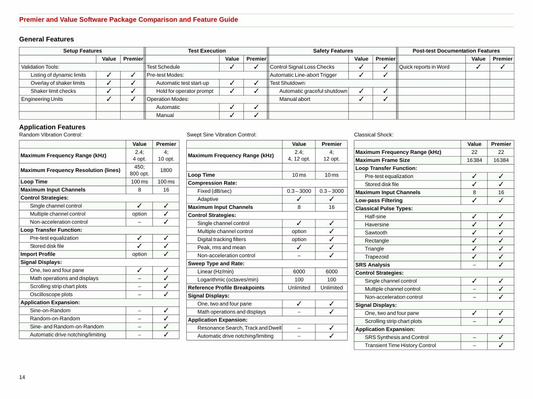
Premier and Value Software Package Comparison and Feature Guide
General Features
Application FeaturesRandom Vibration Control: Swept Sine Vibration Control: Classical Shock:
Setup Features Test Execution Safety Features Post-test Documentation Features
Value Premier Value Premier Value Premier Value Premier
Validation Tools: Test Schedule ✓ ✓ Control Signal Loss Checks ✓ ✓ Quick reports in Word ✓ ✓
Listing of dynamic limits ✓ ✓ Pre-test Modes: Automatic Line-abort Trigger ✓ ✓
Overlay of shaker limits ✓ ✓ Automatic test start-up ✓ ✓ Test Shutdown:
Shaker limit checks ✓ ✓ Hold for operator prompt ✓ ✓ Automatic graceful shutdown ✓ ✓
Engineering Units ✓ ✓ Operation Modes: Manual abort ✓ ✓
Automatic ✓ ✓
Manual ✓ ✓
Value Premier
Maximum Frequency Range (kHz)2.4;
4 opt. 4;
10 opt.
Maximum Frequency Resolution (lines)450;
800 opt.1800
Loop Time 100 ms 100 ms
Maximum Input Channels 8 16
Control Strategies:
Single channel control ✓ ✓
Multiple channel control option ✓
Non-acceleration control – ✓
Loop Transfer Function:
Pre-test equalization ✓ ✓
Stored disk file ✓ ✓
Import Profile option ✓
Signal Displays:
One, two and four pane ✓ ✓
Math operations and displays – ✓
Scrolling strip chart plots – ✓
Oscilloscope plots – ✓
Application Expansion:
Sine-on-Random – ✓
Random-on-Random – ✓
Sine- and Random-on-Random – ✓
Automatic drive notching/limiting – ✓
Value Premier
Maximum Frequency Range (kHz)2.4;
4, 12 opt.4;
12 opt.
Loop Time 10 ms 10 ms
Compression Rate:
Fixed (dB/sec) 0.3 – 3000 0.3 – 3000
Adaptive ✓ ✓
Maximum Input Channels 8 16
Control Strategies:
Single channel control ✓ ✓
Multiple channel control option ✓
Digital tracking filters option ✓
Peak, rms and mean ✓ ✓
Non-acceleration control – ✓
Sweep Type and Rate:
Linear (Hz/min) 6000 6000
Logarithmic (octaves/min) 100 100
Reference Profile Breakpoints Unlimited Unlimited
Signal Displays:
One, two and four pane ✓ ✓
Math operations and displays – ✓
Application Expansion:
Resonance Search, Track and Dwell – ✓
Automatic drive notching/limiting – ✓
Value Premier
Maximum Frequency Range (kHz) 22 22
Maximum Frame Size 16384 16384
Loop Transfer Function:
Pre-test equalization ✓ ✓
Stored disk file ✓ ✓
Maximum Input Channels 8 16
Low-pass Filtering ✓ ✓
Classical Pulse Types:
Half-sine ✓ ✓
Haversine ✓ ✓
Sawtooth ✓ ✓
Rectangle ✓ ✓
Triangle ✓ ✓
Trapezoid ✓ ✓
SRS Analysis – ✓
Control Strategies:
Single channel control ✓ ✓
Multiple channel control – ✓
Non-acceleration control – ✓
Signal Displays:
One, two and four pane ✓ ✓
Scrolling strip chart plots – ✓
Application Expansion:
SRS Synthesis and Control – ✓
Transient Time History Control – ✓
14

Ordering Information
HardwareLAS-200 LASERUSB Shaker Control Systemincluding:• Four inputs• One output• COLA• Digital I/O for remote control
Software Packages
PREMIER SOFTWARE SCO-01P Premier Random Vibration ControlSCO-02P Premier Swept-sine Vibration ControlSCO-03P Premier Classical Shock Transient Control
VALUE SOFTWARE SCO-01V Value Random Vibration Control SCO-02V Value Swept-sine Vibration ControlSCO-03V Value Classical Shock Transient Control
UPGRADE LICENSES (from Value to Premier)SCO-01U Upgrade from Value Random to PremierSCO-02U Upgrade from Value Swept-sine to PremierSCO-03U Upgrade from Value Classical Shock to Premier
Optional Hardware and Software
OPTIONAL HARDWARELAS-201 Single-channel Analog Input (with voltage,
CCLD sensor power and TEDS input coupling)LAS-203 Remote Abort ButtonLAS-204 Rack Mounting KitLAS-210 Channel Expansion BoxACC-101 Wireless Remote Control Pendant (includes
hardware and software)
OPTIONAL PREMIER SOFTWARESCO-01P-01 Sine-on-Random Vibration Control SCO-01P-02 Random-on-Random Vibration ControlSCO-01P-03 Sine- and Random-on-Random Vibration
ControlSCO-01P4 Kurtosis Parameter Control SCO-02P-01 Resonance Search, Track and Dwell Vibration
ControlSCO-03P-01 Transient Time History ControlSCO-03P-02 Shock Response Spectrum Transient ControlSCO-04P Long Time History Road Simulation Control SCO-05P Sine Oscillator
OPTIONAL VALUE SOFTWARESCO-01V-01 Multi-channel Control for Value Random SCO-01V-02 Resolution Extension for Value Random
SCO-01V-03 Frequency Range Extension for Value RandomSCO-01V-04 Import of PSD as Reference for Value RandomSCO-02V-01 Multi-channel Control for Value Swept-sine SCO-02V-02 Tracking Filters for Value Swept-sineSCO-02V-03 Frequency Range Extension for Value Swept-
sine
OPTIONAL GENERAL SOFTWARESCO-100-02 Multi-layer Password Security SystemSCO-100-03 High Frequency ControlSCO-100-06 Advanced Graphics Option (waterfalls and
spectograms)SCO-110 Analyze Anywhere for Shaker ControlSCO-111 Waveform EditorSCO-113 Thermal Chamber Communication and ControlSCO-114 Amplifier Control InterfaceDSA-100-08 Signal Reader (ActiveX® commands to access
binary files)
NETWORK ENABLED SOFTWARENET-103-01 NET-Integrator™ ActiveX Command and
Communication InterfaceNET-104-01 NET-Integrator Run-time License (per seat)
CALIBRATIONCAL-100-02 Re-calibration Software for LASERUSB
15

HETe
Lo
hÎ
BU
3079
–12
2013
-11
Brü
el&
Kjæ
r re
serv
es th
e ri
ght
to c
hang
e sp
ecifi
catio
ns a
nd a
cces
sori
es w
ithou
t no
tice.
ADQUARTERS: Brüel & Kjær Sound & Vibration Measurement A/S · DK-2850 Nærum · Denmarklephone: +45 7741 2000 · Fax: +45 4580 1405 · www.bksv.com/lds · [email protected]
cal representatives and service organisations worldwide
ËBU-3079---
TRADEMARKSMicrosoft, Windows, and ActiveX are registered trademarks of Microsoft Corporation in the United States and/or other countries · MTS is a registered trademark of MTS Systems Corporation© Brüel & Kjær. All rights reserved.


![RANDOM BUILTIN FUNCTION IN STELLA. RANDOM(,, [ ]) The RANDOM builtin generates a series of uniformly distributed random numbers between min and max. RANDOM.](https://static.fdocuments.net/doc/165x107/551463195503462d4e8b59fc/random-builtin-function-in-stella-random-the-random-builtin-generates-a-series-of-uniformly-distributed-random-numbers-between-min-and-max-random.jpg)