Product Data - Carrier Hawaiicarrierhawaii.com/Engineering Catalogs/38MFC 40MFC Product Data.pdf ·...
20
Product Data 40MFC / 38MFC 40MFQ / 38MFQ High---Wall Ductless Split System Sizes 09 to 22 INDUSTRY LEADING FEATURES / BENEFITS A PERFECT BALANCE BETWEEN BUDGET LIMITS, ENERGY SAVINGS AND COMFORT. The 38/40MFC(Q) series ductless split systems are a matched combination of an outdoor condensing unit and an indoor fan coil unit connected only by refrigerant tubing and wires. The fan coil is mounted on the wall, near the ceiling. This selection of fan coils permits creative solutions to design problems such as: S Add--ons to current space (an office or family room addition) S Special space requirements S When changes in the load cannot be handled by the existing system. S When adding air conditioning to spaces that are heated by hydronic or electric heat and have no ductwork. S Historical renovations or any application where preserving the look of the original structure is essential. The ideal compliment to your ducted system when it is impractical or prohibitively expensive to use ductwork. These compact indoor fan coil units take up very little space in the room and do not obstruct windows. The fan coils are attractively styled to blend with most room decors. Advanced system components incorporate innovative technology to provide reliable cooling performance at low sound levels.
Transcript of Product Data - Carrier Hawaiicarrierhawaii.com/Engineering Catalogs/38MFC 40MFC Product Data.pdf ·...

Product Data
40MFC / 38MFC40MFQ / 38MFQHigh---Wall Ductless Split SystemSizes 09 to 22
INDUSTRY LEADINGFEATURES / BENEFITS
A PERFECT BALANCE BETWEENBUDGET LIMITS, ENERGY SAVINGS ANDCOMFORT.The 38/40MFC(Q) series ductless split systems are a matchedcombination of an outdoor condensing unit and an indoor fan coilunit connected only by refrigerant tubing and wires.
The fan coil is mounted on the wall, near the ceiling. Thisselection of fan coils permits creative solutions to design problemssuch as:
S Add--ons to current space (an office or family roomaddition)
S Special space requirements
S When changes in the load cannot be handled by theexisting system.
S When adding air conditioning to spaces that are heatedby hydronic or electric heat and have no ductwork.
S Historical renovations or any application wherepreserving the look of the original structure is essential.
The ideal compliment to your ducted system when it is impracticalor prohibitively expensive to use ductwork.These compact indoor fan coil units take up very little space in theroom and do not obstruct windows. The fan coils are attractivelystyled to blend with most room decors. Advanced systemcomponents incorporate innovative technology to provide reliablecooling performance at low sound levels.

2
LOW SOUND LEVELSWhen noise is a concern, the ductless split systems are the answer.The indoor units are whisper quiet. There are no compressorsindoors, either in the conditioned space or directly over it, andthere is none of the noise usually generated by air being forcedthrough ductwork.When sound ordinances and proximity to neighbors demand quietoperation, the 38MFC,MFQ unit is the right choice: The advanced,horizontal airflow design distributes air more evenly over the coil.
SECURE OPERATIONIf security is an issue, outdoor and indoor units are connected onlyby refrigerant piping and wiring to prevent intruders from crawlingthrough ductwork. In addition, since 38MFC,MFQ units can beinstalled close to an outside wall, coils are protected from vandalsand severe weather.
FAST INSTALLATIONThis compact ductless split system is simple to install. A mountingbracket is standard with the indoor units and only wire and pipingneed to be run between indoor and outdoor units. These units arefast and easy to install ensuring minimal disruption to customers inthe home or workplace. This makes the 38/40MFC,MFQ ductlesssplit systems the equipment of choice, especially in retrofitsituations.
SIMPLE SERVICING ANDMAINTENANCERemoving the top panel on outdoor units provides immediateaccess to the control compartment, providing a service technicianaccess to check unit operation. In addition, the draw--thru design ofthe outdoor section means that dirt accumulates on the outsidesurface of the coil. Coils can be cleaned quickly from the insideusing a pressure hose and detergent.On all indoor units, service and maintenance expense is reduceddue to easy--to--use cleanable filters. In addition, these high wallsystems have extensive self--diagnostics to assist introubleshooting.
BUILT--IN RELIABILITYDuctless split system indoor and outdoor units are designed toprovide years of trouble--free operation.The high wall indoor units include protection against freeze--upand high evaporator temperatures on heat pumps.The condensing units on heat pumps are protected by a threeminute time delay before the compressor will start the over--currentprotection and the high temperature protection.
INDIVIDUAL ROOM COMFORTMaximum comfort is provided because each space can becontrolled individually based on usage pattern. The air sweepfeature provided permits optimal room air mixing to eliminate hotand cold spots for occupant comfort. In addition, year--roundcomfort can be provided with heat pumps.
ECONOMICAL OPERATIONThe ductless split system design allows individual room heating orcooling when required. There is no need to run large supply--airfans or chilled water pumps to handle a few spaces with uniqueload patterns. In addition, because air is moved only in the spacerequired, no energy is wasted moving air through ducts.
EASY--TO--USE CONTROLSThe high--wall units have microprocessor--based controls toprovide the ultimate in comfort and efficiency. The user friendlywireless remote control provides the interface between user and theunit.
ACCESSORIESCustomizing these ductless split systems to your application iseasily accomplished.Adding a condensate pump accessory to the high wall fan coilprovides installation flexibility.
OPTIONAL WIRED CONTROLLER
AGENCY LISTINGSAll systems are listed with AHRI (Air Conditioning, Heating &Refrigeration Institute), and ETL.

3
MODEL NUMBER NOMENCLATURE
OUTDOOR UNIT
38 MFC 1--- --- ---009
38 = Air ---Cooled Condenser
Unit TypeMFC --- Cooling OnlyMFQ --- Heat Pump
Voltage1--- 115---1---603--- 208---230---1---60
INDOOR UNIT
40 MFC 1--- --- ---009
40= Fan Coil Unit
Unit TypeMFC --- Cooling OnlyMFQ --- Heat Pump
Voltage1 --- 115---1---603 --- 208---230---1---60
Nominal Capacity009 --- 3/4 Ton012 --- 1 Ton017 --- 1---3/7 Ton (HP)018 --- 1---1/2 Ton (AC)022 --- 1---5/6 Tons
Nominal Capacity009 --- 3/4 Ton012 --- 1 Ton017 --- 1---3/7 Ton (HP)018 --- 1---1/2 Ton (AC)022 --- 1---5/6 Tons
Use of the AHRI CertifiedTM Mark indicates amanufacturer’s participation in the program For verification of certification for individual products, go to www.ahridirectory.org.

4
STANDARD FEATURES AND ACCESSORIESEase Of InstallationMounting Brackets SLow Voltage Controls S
Comfort FeaturesMicroprocessor Controls SWired Remote Control AWireless Remote Control SAutomatic Horizontal Air Sweep SAir Direction Control SAuto Restart Function SCold Blow Protection On Heat Pumps SFreeze Protection Mode On Heat Pumps STurbo Mode SSilence Mode SAuto Changeover On Heat Pumps S
Energy Saving FeaturesSleep Mode SStop/Start Timer S
Safety And Reliability3 Minute Time Delay For Compressor SOver Current Protection For Compressor SIndoor Coil Freeze Protection SIndoor Coil High Temp Protection in Heating Mode SCondenser High Temp Protection in Cooling Mode S
Ease Of Service And MaintenanceCleanable Filters SDiagnostics SLiquid Line Pressure Taps S
Application FlexibilityCondensate Pumps ACrankcase Heater S
LegendS StandardA Accessory
INDOOR UNITS
A07892
Fig. 1 – Condensate Pump AccessoryOn high wall fan coils, the condensate pump has a lift capability of12 ft (3.6 m) on the discharge side with the pump mounted in thefan coil or 6 ft (1.8 m) on the suction side if the pump is remotemounted. The pump is recommended when adequate drain linepitch cannot be provided, or when the condensate must move up toexit.NOTE: An external 115v power source will be required to run thepump on unit sizes 9k and 12k.
OUTDOOR UNITSCrankcase HeaterStandard on all unit sizes. Heater clamps around compressor oilstump.

5
DIMENSIONS -- INDOOR
A14343
Unit Size W in (mm) D in (mm) H in (mm) Operating Weight lb (kg)9K 26.8 (680) 7.0 (178) 10.0 (255) 15.4 (7)12K 30.3 (770) 7.4 (188) 10.0 (255) 16.5 (7.5)
17K HP / 18K AC 35.6 (905) 7.8 (198) 10.8 (275) 19.8 (9)22K 40.6 (1030) 8.6 (218) 12.4 (315) 26.4 (12)
DIMENSIONS -- OUTDOOR
L2L1
D
A14344
Model W in (mm) D in (mm) H in (mm) L1 in (mm) L2 in (mm)HP
OperatingWeight lb (kg)
ACOperatingWeight lb (kg)
9K 30.7 (780) 9.8 (250) 21.2 (540) 21.6 (549) 10.9 (276) 70.5 (32.0) 58.4 (26.5)12K 30.7 (780) 9.8 (250) 21.2 (540) 21.6 (549) 10.9 (276) 70.5 (32.0) 61.7 (28.0)
17K HP / 18K AC 29.9 (760) 11.2 (285) 23.2 (590) 20.9 (530) 11.4 (290) 82.7 (37.5) 76.0 (47.0)22K 33.3 (845) 12.6 (320) 27.6 (700) 22.0 (560) 13.2 (335) 103.6 (47.0) 98.1 (44.5)
SERVICE VALVE LOCATIONS
J K
9/12K 17/18K 22K
J
K
J K
A14408
Service Valve Locations9K
in. (mm)12K
in. (mm)18K
in. (mm)22K
in. (mm)J 4.37 (111) 4.37 (111) 4.09 (104) 4.13 (105)K 4.61 (117) 4.61 (117) 6.34 (161) 4.13 (105)

6
CLEARANCES -- INDOOR
6" (0.15m) min.
5"(0.13m)
min.
6'
5"(0.13m)
min.
(1.8m)
CEILING
FLOOR
A07891
Fig. 2 – Indoor Unit Clearance
CLEARANCES -- OUTDOOR
A
D B
Air-outlet
Air-inlet
C
E
A07894
UNIT Minimum Valuein. (mm)
A 24 (610)B 24 (610)C 80 (2032)D 12 (305)E 24 (610)
Fig. 3 – Outdoor Unit Clearance

7
SPECIFICATIONS -- COOLING ONLY UNITS (MFC SERIES)System
Size (KBTU/Hr) 09 12 18 22Outdoor Model 38MFC009---1 38MFC012---1 38MFC012---3 38MFC018---3 38MFC022---3Indoor Model 40MFC009---1 40MFC012---1 40MFC012---3 40MFC018---3 40MFC022---3
AHRI Performance Ratings*Cooling Rated Capacity Btu/h 9,000 12,000 18,000 22,000Cooling Cap. Range Min - Max Btu/h 4,000-10,000 4,500-13,000 5,500-19,000 6,500-24,000SEER 15EER 10 9 8.5 10
Operating RangeCooling Outdoor DB Min - Max °F 14 - 115Cooling Indoor DB Min -Max °F 63 - 90
ControlsWireless (°C, °F, Convertible) Standard - ConvertibleWired (°C, °F, Convertible) Optional: KSACN0101CAC
ElectricalSystem Voltage-PH-Hz 115 -1 -60 208-230-1-60Control Voltage 0-15V DCPower Supply Indoor unit powered from outdoor unitOutdoor - MCA 19 19 10 14 16Outdoor - Fuse Rating (MOCP) 30 30 15 20 25
Outdoor MotorRpm/CFM 1000 / 945 940 / 945 860 / 1050 930 / 1390Diameter (in) ... No. of Blades 15.8 … 3 16.7 … 3 18.3 … 3Motor (hp) 0.31 0.33 0.68 0.72Capacitor (µF) / voltage 6 / 250V 2.5 / 400 - 450v 2.5 / 450v
Indoor MotorMotor Watts/ HP 15 / 0.02 15 / 0.02 20 / 0.027 28 / 0.038 45 / 0.061Rpm/CFM (High) 1200 / 192 1200 / 230 1200 / 232 1200 / 348 1200 / 547Rpm/CFM (Medium) 1050 / 160 1050 / 194 1050 / 193 1050 / 294 1050 / 458Rpm/CFM (Low) 900 / 131 900 / 158 900 / 157 900 / 236 900 / 368Blower Diameter / Length (in) 3.7 / 21.3 3.9 / 28.7 4.2 / 30.7Capacitor (µF) 3 1.5 3
RefrigerantRefrigerant Type R410ADesign Pressure (PSIG) 550Metering Device Capillary Tube in Outdoor UnitCharge (lb) 1.34 1.43 1.87 2.60
Refrigerant LinesConnection Type FlarePipe Connection Size - Liquid (In) OD 1/4 3/8Pipe Connection Size - Suction (In) OD 3/8 1/2 5/8Condensate Drain OD / ID (in) 0.65 / 0.63Maximum Piping Length (ft) 65 98Max Lift (Fan Coil Above) (ft) 25 30Max Drop (Fan Coil Below) (ft) 25 30
CompressorType RotaryModel DA108X1C-20FZ3 DA130M1C-31FZ DA150S1C-20FZOil Charge (POE –oz (g)) 16.9 (480) 17.6 (500)Capacitor 45µF / 250VAC 6µF / 450VAC NoneRated Current (RLA) 5.3 3.95 9.7Locked Rotor Amp (LRA) 10 14 17
Outdoor CoilFace Area (sq. ft.) 4.10 6.10 7.67 11.16No. Rows 1 1.5 2Fins per inch 21Circuits 2 4
Indoor CoilFace Area (sq. ft.) 2.53 2.98 1.61 5.29No. Rows 1/2 2Fins per inch 20 21Circuits 2 4 5
Dimensions - OutdoorDimensions (W X H X D) In 35.8 x 23 x 13.2 34.9 x 25.4 x 14 38.0 x 29.7 x 15.6Net Weight (lbs.) 58.4 61.7 76.0 98.1
Dimensions - IndoorDimensions (W X H X D) In 26.8 x 10.0 x 7.0 30.3 x 10.0 x 7.4 35.6 x 10.8 x 7.8 40.6 x 12.4 x 8.6Net Weight (lbs.) 15.4 16.5 19.8 26.4
*Air Conditioning, Heating & Refrigeration Institute--- Ratings are net values reflecting the effects of circulating fan heat. Ratings arebased on: Cooling Standard: 80_F (26.67_C) db, 67_F (19.44_C) wb airentering indoor unit and 95_F (35_C) db air entering outdoor unit. HighTemperature Heating Standard: 70_F (21.11_C) db air entering indoor unit and47_F (8.33_C) db, 43_F (6.11_C) wb air entering outdoor unit.--- Ratings are based on 25 ft. (7.62 m) of interconnecting refrigerant lines.--- All system ratings are based on fan coil units operating at high fan speed.Consult Specification tables for airflows at all available fan speeds.
LegendSEER --- Seasonal Energy Efficiency RatioEER --- Energy Efficiency RatioMCA --- Minimum Circuit AmpsMOCP --- Max. Over---Current Protection

8
SPECIFICATIONS -- HEAT PUMP UNITS (MFQ SERIES)System
Size (KBTU/Hr) 09 12 17 22Outdoor Model 38MFQ009---1 38MFQ012---1 38MFQ012---3 38MFQ017---3 38MFQ022---3Indoor Model 40MFQ009---1 40MFQ012---1 40MFQ012---3 40MFQ017---3 40MFQ022---3
AHRI Performance Ratings*Cooling Rated Capacity Btu/h 9,000 12,000 17,000 22,000Cooling Cap. Range Min - Max Btu/h 4,000-10,000 4,500-13,000 5,500-19,000 6,500-24,000SEER 15EER 10.5 10 9 9.5Heating Rated Capacity Btu/h 9,000 12,000 18,000 22,000Heating Cap. Range Min - Max Btu/h 4,000-10,500 4,500-13,000 5,500-19,500 6,500-24,500HSPF 8.2COP Btuh, W 8.1 8.0 9.7
Operating RangeCooling Outdoor DB Min - Max °F 14 - 115Heating Outdoor DB Min - Max °F 5 - 75Cooling Indoor DB Min - Max °F 63 - 90Heating Indoor DB Min - Max °F 32 - 86
ControlsWireless (°C, °F, Convertible) Standard - ConvertibleWired (°C, °F, Convertible) Optional: KSACN0101CAC
ElectricalSystem Voltage-PH-Hz 115 -1 -60 208-230-1-60Control Voltage 0-15V DCPower Supply Indoor unit powered from outdoor unitOutdoor - MCA 19 10 14 16Outdoor - Fuse Rating (MOCP) 30 15 20 25
Outdoor MotorRpm/CFM 1000 / 945 940 / 945 860 / 1050 930 / 1390Diameter (in) ... No. of Blades 15.8 … 3 16.7 … 3 18.3 … 3Motor (hp) 0.31 0.33 0.68 0.72Capacitor (µF) 6 2.5
Indoor MotorMotor Watts/ HP 15 / 0.02 15 / 0.02 20 / 0.027 28 / 0.038 45 / 0.061Rpm/CFM (High) 1200 / 192 1200 / 230 1200 / 232 1200 / 348 1200 / 547Rpm/CFM (Medium) 1050 / 160 1050 / 194 1050 / 193 1050 / 294 1050 / 458Rpm/CFM (Low) 900 / 131 900 / 158 900 / 157 900 / 236 900 / 368Blower Diameter / Length (in) 3.7 / 21.3 3.9 / 28.7 4.2 / 30.7Capacitor (µF) 3 1.5 3
RefrigerantRefrigerant Type R410ADesign Pressure (PSIG) 550Metering Device Capillary Tube in Outdoor UnitCharge (lb) 2.6 2.87 3.52
Refrigerant LinesConnection Type FlarePipe Connection Size - Liquid (In) OD 1/4 3/8Pipe Connection Size - Suction (In) OD 3/8 1/2 5/8Condensate Drain OD / ID (in) 0.65 / 0.63Maximum Piping Length (ft) 65 98Max Lift (Fan Coil Above) (ft) 25 30Max Drop (Fan Coil Below) (ft) 25 30
CompressorType RotaryModel DA108X1C-20FZ3 DA130M1C-31FZ DA150S1C-20FZOil Charge (POE –oz (g)) 16.9 (480) 17.6 (500)Capacitor 45µF / 250VAC 6µF / 450VAC NoneRated Load Amps (RLA) 5.3 3.95 9.7Locked Rotor Amp (LRA) 10 14 17
Outdoor CoilFace Area (sq. ft.) 8.19 7.81 11No. Rows 2Fins per inch 17 18Circuits 3 4
Indoor CoilFace Area (sq. ft.) 2.53 2.98 1.61 5.29No. Rows 1/2 2Fins per inch 20 21Circuits 2 4 5
Dimensions - OutdoorDimensions (W X H X D) In 35.8 x 23 x 13.2 34.9 x 25.4 x 14 38.0 x 29.7 x 15.6Net Weight (lbs.) 70.5 82.7 103.6
Dimensions - IndoorDimensions (W X H X D) In 26.8 x 10.0 x 7.0 30.3 x 10.0 x 7.4 35.6 x 10.8 x 7.8 40.6 x 12.4 x 8.6Net Weight (lbs.) 15.4 16.5 19.8 26.4
*Air Conditioning, Heating & Refrigeration Institute--- Ratings are net values reflecting the effects of circulating fan heat. Ratings arebased on: Cooling Standard: 80_F (26.67_C) db, 67_F (19.44_C) wb airentering indoor unit and 95_F (35_C) db air entering outdoor unit. HighTemperature Heating Standard: 70_F (21.11_C) db air entering indoor unit and47_F (8.33_C) db, 43_F (6.11_C) wb air entering outdoor unit.--- Ratings are based on 25 ft. (7.62 m) of interconnecting refrigerant lines.--- All system ratings are based on fan coil units operating at high fan speed.Consult Specification tables for airflows at all available fan speeds.
LegendSEER --- Seasonal Energy Efficiency RatioEER --- Energy Efficiency RatioHSPF --- Heating Seasonal Performance FactorCOP --- Coefficient of PerformanceMCA --- Minimum Circuit AmpsMOCP --- Max. Over---Current Protection

9
COOLING PERFORMANCE DATA -- 38/40MFC (COOLING ONLY)
Model38---40MFC
Cooling Outdoor conditions (DB) ° FIndoor ConditionsDB/WB ° F (BTU/h) 77 86 95 104 113 122
009
69.8/59TC 5.71 7.90 8.88 7.45 6.20 5.18SC 3.70 5.22 6.04 5.23 4.50 3.85Input 0.48 0.76 1.00 0.98 0.95 0.90
75.2/62.6TC 6.12 8.51 9.70 8.30 7.02 5.91SC 3.93 5.54 6.46 5.69 5.00 4.42Input 0.48 0.77 1.01 1.00 0.97 0.92
80.6/66.2TC 6.55 9.35 10.69 9.01 7.43 6.08SC 4.25 6.06 7.04 6.12 5.26 4.50Input 0.49 0.79 1.03 1.02 0.99 0.94
89.6/73.4TC 6.67 9.86 11.75 10.36 8.95 7.62SC 4.03 5.94 7.11 6.39 5.72 5.15Input 0.49 0.79 1.05 1.05 1.03 0.99
012(115v)
69.8/59TC 5.94 8.63 10.38 8.52 5.60 4.68SC 3.65 5.41 6.69 5.67 3.85 3.30Input 0.58 0.97 1.35 1.29 0.99 0.94
75.2/62.6TC 6.37 9.29 11.34 9.48 6.35 5.34SC 3.88 5.74 7.16 6.16 4.29 3.79Input 0.58 0.97 1.37 1.31 1.01 0.97
80.6/66.2TC 6.82 10.21 12.50 10.30 6.71 5.50SC 4.20 6.27 7.81 6.64 4.51 3.86Input 0.59 0.99 1.39 1.34 1.03 0.99
89.6/73.4TC 6.95 10.77 13.73 11.84 8.09 6.89SC 3.98 6.15 7.88 6.93 4.90 4.41Input 0.59 1.00 1.42 1.38 1.07 1.03
012(208---230V)
69.8/59TC 5.92 8.58 10.33 8.47 5.57 4.66SC 3.59 5.32 6.57 5.57 3.79 3.25Input 0.57 0.95 1.33 1.27 0.97 0.93
75.2/62.6TC 6.34 9.24 11.28 9.43 6.32 5.32SC 3.81 5.64 7.03 6.05 4.21 3.72Input 0.58 0.96 1.35 1.30 1.00 0.95
80.6/66.2TC 6.78 10.16 12.44 10.24 6.68 5.47SC 4.13 6.17 7.67 6.52 4.43 3.79Input 0.59 0.98 1.37 1.32 1.02 0.97
89.6/73.4TC 6.91 10.72 13.66 11.79 8.05 6.85SC 3.91 6.04 7.75 6.80 4.82 4.34Input 0.58 0.98 1.40 1.36 1.06 1.02
018
69.8/59TC 12.34 14.95 14.96 10.83 8.16 6.65SC 7.90 9.77 10.05 7.52 5.85 4.89Input 1.25 1.73 2.01 1.70 1.49 1.38
75.2/62.6TC 13.22 16.10 16.34 12.06 9.25 7.59SC 8.38 10.37 10.75 8.17 6.51 5.60Input 1.25 1.74 2.03 1.73 1.52 1.42
80.6/66.2TC 14.15 17.70 18.02 13.10 9.79 7.80SC 9.08 11.33 11.73 8.80 6.85 5.71Input 1.28 1.78 2.08 1.76 1.55 1.45
89.6/73.4TC 14.42 18.66 19.80 15.07 11.79 9.78SC 8.61 11.10 11.85 9.18 7.44 6.53Input 1.26 1.79 2.12 1.82 1.62 1.52
022
69.8/59TC 17.19 19.41 19.49 16.59 14.03 11.96SC 11.68 13.45 13.88 12.21 10.67 9.33Input 1.49 1.92 2.23 2.22 2.18 2.12
75.2/62.6TC 18.43 20.91 21.28 18.47 15.90 13.66SC 12.39 14.28 14.85 13.27 11.86 10.70Input 1.49 1.93 2.26 2.26 2.23 2.18
80.6/66.2TC 19.72 22.99 23.47 20.06 16.81 14.05SC 13.43 15.61 16.20 14.29 12.49 10.90Input 1.52 1.97 2.31 2.31 2.28 2.23
89.6/73.4TC 20.09 24.24 25.79 23.07 20.26 17.61SC 12.72 15.29 16.36 14.91 13.57 12.46Input 1.50 1.98 2.35 2.38 2.37 2.33
LEGENDDB --- Dry BulbWB --- Wet BulbTC --- Total Net Cooling Capacity (1000 Btu/hour)SC --- Sensible Capacity (1000 Btu/hour)Input --- Total Power (kW)

10
COOLING PERFORMANCE DATA -- 38/40MFQ (HEAT PUMP)
Model38---40MFQ
Cooling Outdoor conditions (DB) ° FIndoor ConditionsDB/WB ° F (BTU/h) 77 86 95 104 113 122
009
69.8/59TC 5.29 7.79 8.75 7.35 6.11 5.11SC 3.38 5.07 5.86 5.08 4.36 3.74Input 0.43 0.73 0.95 0.93 0.90 0.86
75.2/62.6TC 5.67 8.39 9.57 8.18 6.92 5.83SC 3.58 5.38 6.27 5.52 4.85 4.29Input 0.43 0.73 0.96 0.95 0.92 0.88
80.6/66.2TC 6.07 9.22 10.54 8.89 7.32 6.00SC 3.88 5.88 6.83 5.94 5.11 4.37Input 0.44 0.75 0.98 0.97 0.94 0.90
89.6/73.4TC 6.18 9.72 11.59 10.22 8.82 7.51SC 3.68 5.76 6.90 6.20 5.55 5.00Input 0.44 0.75 1.00 1.00 0.98 0.94
012(115v)
69.8/59TC 6.14 8.92 10.16 8.80 5.79 4.84SC 3.76 5.57 6.52 5.84 3.97 3.40Input 0.56 0.92 1.22 1.23 0.94 0.90
75.2/62.6TC 6.59 9.60 11.09 9.80 6.56 5.52SC 3.99 5.91 6.98 6.35 4.41 3.90Input 0.56 0.93 1.23 1.25 0.96 0.92
80.6/66.2TC 7.05 10.56 12.23 10.64 6.94 5.68SC 4.33 6.46 7.61 6.84 4.65 3.97Input 0.57 0.95 1.26 1.28 0.98 0.94
89.6/73.4TC 7.18 11.14 13.44 12.24 8.36 7.12SC 4.10 6.33 7.69 7.13 5.05 4.54Input 0.56 0.95 1.28 1.32 1.02 0.99
012(208---230V)
69.8/59TC 6.14 8.91 10.15 8.80 5.79 4.84SC 3.73 5.53 6.47 5.79 3.94 3.38Input 0.57 0.94 1.24 1.25 0.96 0.91
75.2/62.6TC 6.58 9.60 11.09 9.80 6.56 5.52SC 3.96 5.87 6.92 6.29 4.38 3.87Input 0.57 0.94 1.25 1.27 0.98 0.94
80.6/66.2TC 7.05 10.56 12.23 10.64 6.94 5.68SC 4.29 6.41 7.55 6.78 4.61 3.94Input 0.58 0.96 1.28 1.30 1.00 0.96
89.6/73.4TC 7.18 11.13 13.44 12.24 8.36 7.12SC 4.06 6.28 7.62 7.08 5.01 4.51Input 0.57 0.97 1.30 1.34 1.04 1.00
017
69.8/59TC 12.58 15.24 15.25 11.04 8.32 6.78SC 8.34 10.30 10.60 7.93 6.18 5.16Input 1.19 1.65 1.92 1.62 1.42 1.32
75.2/62.6TC 13.48 16.41 16.66 12.30 9.43 7.74SC 8.85 10.94 11.35 8.62 6.87 5.91Input 1.19 1.66 1.94 1.65 1.45 1.35
80.6/66.2TC 14.43 18.04 18.37 13.35 9.97 7.96SC 9.59 11.95 12.37 9.28 7.23 6.02Input 1.22 1.70 1.98 1.68 1.48 1.38
89.6/73.4TC 14.70 19.03 20.18 15.36 12.02 9.97SC 9.08 11.72 12.50 9.69 7.85 6.89Input 1.21 1.71 2.02 1.73 1.54 1.45
022
69.8/59TC 16.27 18.37 18.44 15.70 13.27 11.32SC 10.99 12.65 13.06 11.49 10.03 8.78Input 1.46 1.88 2.19 2.18 2.14 2.08
75.2/62.6TC 17.44 19.79 20.14 17.48 15.05 12.93SC 11.65 13.43 13.97 12.48 11.16 10.07Input 1.46 1.89 2.22 2.21 2.19 2.14
80.6/66.2TC 18.67 21.75 22.21 18.98 15.91 13.30SC 12.63 14.68 15.24 13.45 11.75 10.25Input 1.49 1.93 2.26 2.26 2.23 2.18
89.6/73.4TC 19.01 22.94 24.40 21.84 19.17 16.66SC 11.97 14.39 15.39 14.03 12.76 11.73Input 1.47 1.94 2.31 2.33 2.32 2.29
LEGENDDB --- Dry BulbWB --- Wet BulbTC --- Total Net Cooling Capacity (1000 Btu/hour)SC --- Sensible Capacity (1000 Btu/hour)Input --- Total Power (kW)
11
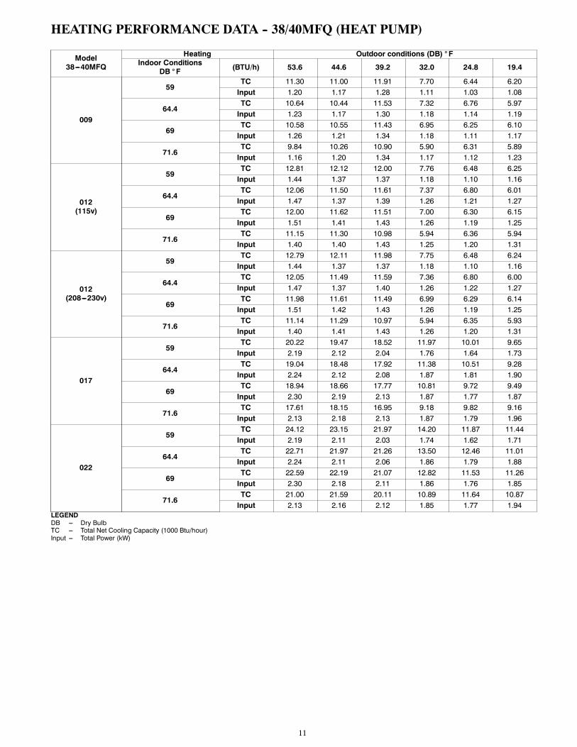
HEATING PERFORMANCE DATA -- 38/40MFQ (HEAT PUMP)
Model38---40MFQ
Heating Outdoor conditions (DB) ° FIndoor Conditions
DB ° F (BTU/h) 53.6 44.6 39.2 32.0 24.8 19.4
009
59TC 11.30 11.00 11.91 7.70 6.44 6.20Input 1.20 1.17 1.28 1.11 1.03 1.08
64.4TC 10.64 10.44 11.53 7.32 6.76 5.97Input 1.23 1.17 1.30 1.18 1.14 1.19
69TC 10.58 10.55 11.43 6.95 6.25 6.10Input 1.26 1.21 1.34 1.18 1.11 1.17
71.6TC 9.84 10.26 10.90 5.90 6.31 5.89Input 1.16 1.20 1.34 1.17 1.12 1.23
012(115v)
59TC 12.81 12.12 12.00 7.76 6.48 6.25Input 1.44 1.37 1.37 1.18 1.10 1.16
64.4TC 12.06 11.50 11.61 7.37 6.80 6.01Input 1.47 1.37 1.39 1.26 1.21 1.27
69TC 12.00 11.62 11.51 7.00 6.30 6.15Input 1.51 1.41 1.43 1.26 1.19 1.25
71.6TC 11.15 11.30 10.98 5.94 6.36 5.94Input 1.40 1.40 1.43 1.25 1.20 1.31
012(208---230v)
59TC 12.79 12.11 11.98 7.75 6.48 6.24Input 1.44 1.37 1.37 1.18 1.10 1.16
64.4TC 12.05 11.49 11.59 7.36 6.80 6.00Input 1.47 1.37 1.40 1.26 1.22 1.27
69TC 11.98 11.61 11.49 6.99 6.29 6.14Input 1.51 1.42 1.43 1.26 1.19 1.25
71.6TC 11.14 11.29 10.97 5.94 6.35 5.93Input 1.40 1.41 1.43 1.26 1.20 1.31
017
59TC 20.22 19.47 18.52 11.97 10.01 9.65Input 2.19 2.12 2.04 1.76 1.64 1.73
64.4TC 19.04 18.48 17.92 11.38 10.51 9.28Input 2.24 2.12 2.08 1.87 1.81 1.90
69TC 18.94 18.66 17.77 10.81 9.72 9.49Input 2.30 2.19 2.13 1.87 1.77 1.87
71.6TC 17.61 18.15 16.95 9.18 9.82 9.16Input 2.13 2.18 2.13 1.87 1.79 1.96
022
59TC 24.12 23.15 21.97 14.20 11.87 11.44Input 2.19 2.11 2.03 1.74 1.62 1.71
64.4TC 22.71 21.97 21.26 13.50 12.46 11.01Input 2.24 2.11 2.06 1.86 1.79 1.88
69TC 22.59 22.19 21.07 12.82 11.53 11.26Input 2.30 2.18 2.11 1.86 1.76 1.85
71.6TC 21.00 21.59 20.11 10.89 11.64 10.87Input 2.13 2.16 2.12 1.85 1.77 1.94
LEGENDDB --- Dry BulbTC --- Total Net Cooling Capacity (1000 Btu/hour)Input --- Total Power (kW)

12
APPLICATION DATAUNIT SELECTIONSelect equipment to either match or be slightly less than anticipatedpeak load. This provides better humidity control, fewer unit cycles,and less part--load operation.For units used in spaces with high sensible loads, base equipmentselection on unit sensible load, not on total anticipated load. Adjustfor anticipated room wet bulb temperature to avoid undersizingequipment.
UNIT MOUNTING (INDOOR)Refer to unit Installation Instructions for further details.Unit leveling -- For reliable operation, units should be level in allplanes.Clearance -- Provide adequate clearance for airflow as shown inFig. 2.Unit location -- Select a location which will provide the best aircirculation for the room.These units should be positioned as high as possible on the wall forbest air circulation. The unit return and discharge should not beobstructed by furniture, curtains, or anything which may cause unitshort cycling or air recirculation. Place the unit in the middle of theselected wall (if possible). Use an outside wall, if available, tomake piping easier, and place the unit so it faces the normallocation of room occupants.
UNIT MOUNTING (OUTDOOR)Refer to unit Installation Instructions for further details.Unit leveling -- For reliable operation, units should be level in allplanes.Clearance -- Minimum clearance, as shown in Fig. 3, must beprovided for airflow. The condensing units are designed forfree--blow application. Air inlets and outlets should not berestricted.Unit location -- A location which is convenient to installation andnot exposed to strong wind.A location which can bear the weight of outdoor unit and wherethe outdoor unit can be mounted in a level position.Do not install the indoor or outdoor units in a location with specialenvironmental conditions. For those applications, contact yourCarrier representative.
MOUNTING TEMPLATERefer to unit Installation Instructions for further details.The fan coil units are furnished with mounting to mark the locationof the wiring, and refrigeration line hole locations.
SUPPORTAdequate support must be provided to support the weight of all fancoils. Refer to the Physical Data section for fan coil weights, andthe base unit dimensional drawings for the location of mountingbrackets.
SYSTEM OPERATING CONDITIONSOperating RangeMin / Max °F (°C)
Cooling Heating
Outdoor DB 14 / 115 (-10 / 46) 5 / 75 (-15 / 24)
Indoor DB 63 / 90 (17 / 32) 32 / 86 (0 / 30)
Indoor WB 59 / 84 (15 / 29) 4.1 / 70.7 (-15.5 / 21.5)
Non-Operating Temperature RangeMin / Max °F (°C)
Indoor/Outdoor DB 32 / 86 (0 / 30)
NOTE: Reference the Product Installation Instructions for more information.
METERING DEVICESThese units have capillary tube metering devices in the outdoorunit.
DRAIN CONNECTIONSInstall drains to meet local sanitation codes. If adequate gravitydrainage cannot be provided, unit should be equipped withaccessory condensate pump. High wall fan coil unit condensatepumps have a maximum lift of 10’ (3.05 m) for 9k and 12k unitsand 25’ (7.62 m) for 18k and 22k units.See physical dimension tables for drain sizes.NOTE: High wall fan coil units have internal condensate traps.A trap is not required.Drain connections may be routed through alternate locations onmost fan coils as shown in Fig. 4.
Pipe holder
Pipe cover
Right piping
Left piping
Pipe cover
Right back piping
Left back piping
1 2
3
4
A14349Fig. 4 – Piping Locations
REFRIGERANT LINESGeneral refrigerant line sizing:
1. The 38MFC/MVQ units are shipped with a full charge ofR410A refrigerant. All charges, line sizing, and capacitiesare based on runs of 25 ft (7.6 m). For runs over 25 ft (7.6m), consult long--line section on this page for proper chargeadjustments.
2. Refrigerant lines should not be buried in the ground. If it isnecessary to bury the lines, not more than 36--in (914 mm)should be buried. Provide a minimum 6--in (152 mm)vertical rise to the service valves to prevent refrigerantmigration.
3. Both lines must be insulated. Use a minimum of 1/2--in.(12.7 mm) thick insulation. Closed--cell insulation isrecommended in all long--line applications.
4. Special consideration should be given to isolatinginterconnecting tubing from the building structure. Isolatethe tubing so that vibration or noise is not transmitted intothe structure.
Long Line Applications, 38MFC Units:1. No change in line sizing is required.2. Add refrigerant per table below.
ADDITIONAL CHARGE TABLE
UnitSize
Total LineLength ft
Additional Charge, oz/ft.ft (m)
Min Max 10 --- 25(3 --- 8)
>25 --- 65(8 --- 20)
>65 --- 98(20 --- 30)
9K
10 65 None 0.1612K18K AC17K HP22K 98 0.32 0.32
3. Reduction in capacity due to long lines can be calculatedfrom the chart below.
CAPACITY LOSSCapacity,% Loss
Line Length ft (m)Cooling: 25 (7.5) 33 (10) 49 (15) 65 (20) 98(30)9&12K 1% 2% 5% 7% ---18&22K 1% 2% 4% 6% 8%Heating:9&12K 1% 2% 7% 11% ---17&22K 1% 2% 6% 10% 15%

13
WIRINGRecommended Connection Method for Power and Communi-cation Wiring (To minimize communication wiring interfer-ence)Power Wiring:The main power is supplied to the outdoor unit. The field suppliedconnecting cable from the outdoor unit to indoor unit consists ofthree (3) wires and provides the power for the indoor unit. Twowires are high voltage AC power and one is a ground wire.Consult your local building codes and the NEC (NationalElectrical Code) or CEC (Canadian Electrical Code) for specialrequirements.All wires must be sized per NEC or CEC and local codes. UseElectrical Data table MCA (minimum circuit amps) and MOCP(maximum over current protection) to correctly size the wires andthe disconnect fuse or breakers respectively.Per caution note, only copper conductors with a minimum 300 voltrating and 2/64--inch thick insulation must be used.Communication Wiring:A separate shielded copper conductor only, with a minimum 300volt rating and 2/64--inch thick insulation, must be used as thecommunication wire from the outdoor unit to the indoor unit.To minimize voltage drop of the control wire, use the followingwire size and maximum lengths shown in the chart below:
Wire Size Lengthft (m)
18 AWG 50 (15)16 AWG 50 (15) to 100 (30)
Alternate Connection Method for Power and CommunicationWiring (May not prevent communication wiring interference)The main power is supplied to the outdoor unit. The field suppliedconnecting cable from the outdoor unit to indoor unit consists offour (4) wires and provides the power and communication signalsfor the indoor unit. Two conductors are for power wiring (L1/L2,or L/N), one is a ground wire, and one is a DC communicationwire.Consult your local building codes and the NEC (NationalElectrical Code) or CEC (Canadian Electrical Code) for specialrequirements. All power wires must be sized per NEC or CEC andlocal codes. Use Electrical Data table MCA (minimum circuitamps) and MOCP (maximum over current protection) to correctlysize the wires and the disconnect fuse or breakers respectively.Per caution note, only copper conductors with a minimum 300 voltrating and 2/64--inch thick insulation must be used.
CAUTION!
EQUIPMENT DAMAGE HAZARD
Failure to follow this caution may result in equipmentdamage or improper operation.
S Wires should be sized based on NEC and local codes.
S Use copper conductors only with a minimum 300 voltrating and 2/64 inch thick insulation.
CAUTION!
EQUIPMENT DAMAGE HAZARD
Failure to follow this caution may result in equipmentdamage or improper operation.S Be sure to comply with local codes while running wire
from indoor unit to outdoor unit.S Every wire must be connected firmly. Loose wiring
may cause terminal to overheat or result in unitmalfunction. A fire hazard may also exist. Therefore,be sure all wiring is tightly connected.
S No wire should be allowed to touch refrigerant tubing,compressor or any moving parts.
S Disconnecting means must be provided and shall belocated within sight and readily accessible from the airconditioner.
S Connecting cable with conduit shall be routed throughhole in the conduit panel.
The main power is supplied to the outdoor unit. the field suppliedconnecting cable from the outdoor unit to indoor unit consists offour wires and provides the power for the indoor unit as well as thecommunication signal between the outdoor unit and indoor unit.Two wires are high voltage AC power (L1 and L2), one is aground wire, and one is a DC communication wire.
CONTROL SYSTEMThe 40MFC/MFQ unit is equipped with a microprocessor controlto perform two functions:
1. Provide safety for the system2. Control the system and provide optimum levels of comfortand efficiency
The main microprocessor is located on the control board of the fancoil unit (outdoor units have a microprocessor too) withthermistors located in the fan coil air inlet and on the indoor coil.Heat pump units have a thermistor on the outdoor coil. Thesethermistors monitor the system operation to maintain the unitwithin acceptable parameters and control the operating mode.
WIRELESS REMOTE CONTROL1. A wireless remote control is supplied forsystem operation of all high--wall units.
2. Each battery--operated wireless (infrared)remote control may be used to control morethan one unit.
WIRED REMOTE CONTROL (OPTIONAL)P/N KSACN0101CAC
1. Optional wired remote controller usedfor system operation of all high--wallunits.
2. Kit includes a wired remote controllerand a connecting cable.
3. Connect with wire terminal betweenremote controller and indoor unit.
4. Display in _F or _C and temperatureincrements every 1_F or every 1_C.

14
AIR THROW DATAUNIT
CAPACITYAPPROXIMATE AIR THROW ft. (m)
Low Medium High
009 115v 11 (3.5) 15 (4.5) 21 (6.5)
012 115v 14 (4.2) 17 (5.1) 23 (7.0)
012 208/230v 14 (4.2) 17 (5.1) 23 (7.0)
018 208/230v 16 (5.0) 20 (6.2) 28 (8.5)
022 208/230v 19 (5.7) 23 (7.0) 31 (9.5)
SOUND RATINGSOutdoor Units
Model Number Sound Power dBa Sound Pressure dBa
38MFC(Q)009--- --- ---1 67 57
38MFC(Q)012--- --- ---1 67 58
38MFC(Q)012--- --- ---3 67 58
38MFC017 / 38MFC018--- --- ---3 70 60
38MFC(Q)022--- --- ---3 72 61
Indoor Units
Model NumberHigh Medium Low
Sound PowerdBa
Sound PressuredBa
Sound PowerdBa
Sound PressuredBa
Sound PowerdBa
Sound PressuredBa
40MFC009--- --- ---1 52 43 48 39 43 34
40MFC012--- --- ---1 53 44 49 40 45 36
40MFC012--- --- ---3 53 44 49 40 45 36
40MFC018--- --- ---3 55 45 51 41 47 37
40MFC022--- --- ---3 60 50 56 46 52 42
40MFQ009--- --- ---1 52/49 (Clg/Htg) 43/40 (Clg/Htg) 48/44 (Clg/Htg) 39/35 (Clg/Htg) 43/39 (Clg/Htg) 34/30 (Clg/Htg)
40MFQ012--- --- ---1 53/52 (Clg/Htg) 44/43 (Clg/Htg) 49/47 (Clg/Htg) 40/38 (Clg/Htg) 45/52 (Clg/Htg) 36/33 (Clg/Htg)
40MFQ012--- --- ---3 53/51 (Clg/Htg) 44/42 (Clg/Htg) 49/45 (Clg/Htg) 40/36 (Clg/Htg) 45/40 (Clg/Htg) 36/31 (Clg/Htg)
40MFQ017--- --- ---3 55/52 (Clg/Htg) 45/42 (Clg/Htg) 51/48 (Clg/Htg) 41/38 (Clg/Htg) 47/43 (Clg/Htg) 37/33 (Clg/Htg)
40MFQ022--- --- ---3 60/56 (Clg/Htg) 50/46 (Clg/Htg) 56/52 (Clg/Htg) 46/42 (Clg/Htg) 52/48 (Clg/Htg) 42/38 (Clg/Htg)NOTES:1. Sound power ratings are per AHRI 270 and AHRI 3502. Sound pressure ratings are estimated sound pressure, 3 feet (.91 m) from the unit, based on sound power data.
ELECTRICAL DATA
UNIT SIZE
OPER.VOLTAGEMAX / MIN*
COMPRESSOR OUTDOOR FAN INDOOR FANMCA MAX FUSE
CB AMPV---PH---HZ RLA LRA V---PH---HZ FLA HP W V---PH---HZ FLA HP W
9K127 / 104 115---1---60 5.3 10 115---1---60 0.7 0.31 23 115---1---60 0.3 0.020 15 19 30
12K
12K
253 / 187 208---230---1---60
5.3 10
208---230---1---60
0.3 0.33 24
208---230---1---60
0.2 0.027 20 10 15
017K (HP)018K (AC)
3.95 14 0.6 0.68 50 0.3 0.038 28 14 20
22K 9.7 17 0.6 0.72 53 0.4 0.061 45 16 25
*Permissible limits of the voltage range at which the unit will operate satisfactorilyLEGENDFLA --- Full Load AmpsLRA --- Locked Rotor AmpsMCA --- Minimum Circuit AmpsRLA --- Rated Load Amps

15
WIRINGDIAGRAMSN
OTAG
INDO
OR W
IRIN
G DI
AGRA
M
M CN5
YELL
OW
RED
DI
SPLA
Y BO
ARD
5 CN10
A
CN11
CN8
CN9
P_1
8CN
16
L_IN
LN
S
U V W
BLUE
U V W
4
CN28
CN26
CN10
(CN1
9)N-
B
CN15
CN16
L2
N-A
Y/G
RED
BLUE
BLAC
K
5
CN34
CN33 CN
6
CN7
CN5
CN4
L N
S
BROW
N
BLUE
YELL
OW
Y/G
Y/GN
LN
BLAC
KBL
ACK
L-A(
CN37
)L-
B(CN
36)
RED
RED
REA
CTO
R
RY3
GND
CN8
CN9
HEA
TER,
CRA
NKC
ASE
T
RED
BLAC
K
CS
Y/G
Powe
r Inp
ut
GND
2020
375A
5475
2020
325B
3267
Das
hed
fram
e p
arts
on
ly fo
r hea
t p
um
p m
od
el.
M ~3(
2)3
64
FAN C APAC ITOR BOARDFAN C APAC ITOR BOARD
Op
tio
nal
CN 2
CO
DE
PA
RT
NA
ME
L_IN
Fire
Wire
L in
put t
erm
inal
CN
11Ze
ro lin
e N
inpu
t ter
min
alC
N16
Inte
rnal
and
ext
erna
l com
mun
icat
ion
line
inte
rface
CN
6In
door
fan
inte
rface
CN
4Fa
n fe
edba
ck in
terfa
ceC
N5
Ste
pper
mot
or in
terfa
ceP
_1G
roun
d in
terfa
ceC
N8
Roo
m te
mpe
ratu
re s
enso
r int
erfa
ceC
N9
Pip
e te
mpe
ratu
re s
enso
r int
erfa
ceC
N10
AD
ispl
ay in
terfa
ceC
N1
Elec
troni
c ex
pans
ion
valv
e in
terfa
ceC
N14
Com
pres
sor t
op te
mpe
ratu
re s
enso
r (op
tiona
l)C
N15
Exha
ust t
empe
ratu
re s
enso
rC
N16
Out
door
tem
pera
ture
& a
mp;
con
dens
er p
ipe
tem
pera
ture
sen
sor
CN
10D
C fa
n ou
tput
por
t (no
)C
N19
AC
fan
outp
ut p
ort
CN
33El
ectri
c he
atin
g w
ire lin
e N
C
N34
Elec
tric
heat
ing
wire
line
LC
N26
,CN
28Fo
ur w
ay v
alve
con
trol p
ort
CN
4P
ower
L in
put t
erm
inal
CN
5P
ower
N in
put t
erm
inal
CN
6G
roun
d w
ireC
N7
Com
mun
icat
ion
line
CN
8,C
N9
Rea
ctor
con
nect
ed lin
e po
rtC
N36
,CN
37P
FC c
apac
itor c
onne
cted
line
port
N-B
Pow
er L
inpu
t ter
min
alC
N17
Test
pan
el in
terfa
ceU
V W
Com
pres
sor c
onne
ctio
n po
rt
OUTD
OOR
WIR
ING
DIAG
RAM
Fig.5
–WiringDiagram
38/40M
FC/M
FQ009/38/40MFC/M
FQ012(115V)

16
WIRINGDIAGRAMS(CONT.)
CN10
B
CN3
CN2
CN15
CN16
5
WHI
TEW
HITE
BLAC
K
BLAC
K
BLAC
KBL
ACK
2020
375A
5477
CN28
CN26
CN34
CN33
RED
BLAC
K
BLUE
4
L2
N-A
RY3
CS
U V WU V W
Y/G
RED
BLUE
BLAC
K
CN6
CN7
CN5
CN4
L N
S
BROW
N
BLUE
YELL
OW
Y/G
Y/G
LN
GND
Y/G
Powe
r Inp
ut
INDO
OR W
IRIN
G DI
AGRA
M
M CN5
YELL
OW
RED
DI
SPLA
Y BO
ARD
5
CN10
A
CN11
CN8
CN9
P_1
8CN
16
L_IN
L1L2
S
GND
HEA
TER,
CRA
NKC
ASE
T
2020
328A
7163
Das
hed
fram
e p
arts
on
ly fo
r hea
t p
um
p m
od
el.
M ~3(
2)3
Op
tio
nal
CN2
CO
DE
PA
RT
NA
ME
L_IN
Fire
Wire
L in
put t
erm
inal
CN
11Ze
ro lin
e N
inpu
t ter
min
alC
N16
Inte
rnal
and
ext
erna
l com
mun
icat
ion
line
inte
rface
CN
6In
door
fan
inte
rface
CN
4Fa
n fe
edba
ck in
terfa
ceC
N5
Ste
pper
mot
or in
terfa
ceP
_1G
roun
d in
terfa
ceC
N8
Roo
m te
mpe
ratu
re s
enso
r int
erfa
ceC
N9
Pip
e te
mpe
ratu
re s
enso
r int
erfa
ceC
N10
AD
ispl
ay in
terfa
ceC
N14
Com
pres
sor t
op te
mpe
ratu
re s
enso
r (op
tiona
l)C
N15
Exha
ust t
empe
ratu
re s
enso
rC
N16
Out
door
tem
pera
ture
&am
p; c
onde
nser
pip
e te
mpe
ratu
re s
enso
rC
N26
,CN
28Fo
ur w
ay v
alve
con
trol p
ort
CN
10A
C fa
n ou
tput
por
tC
N32
,CN
34El
ectri
c he
atin
g w
ire lin
e N
C
N31
,CN
33El
ectri
c he
atin
g w
ire lin
e L
CN
4P
ower
L in
put t
erm
inal
CN
5P
ower
N in
put t
erm
inal
CN
6G
roun
d w
ireC
N7
Com
mun
icat
ion
line
N-B
Pow
er L
inpu
t ter
min
alC
N2,
CN
3R
eact
or c
onne
cted
line
port
CN
17Te
st p
anel
inte
rface
U V
WC
ompr
esso
r con
nect
ion
port
OUTD
OOR
WIR
ING
DIAG
RAM
Fig.6
–WiringDiagram
38/40M
FC/M
FQ012(208--230V)

17
WIRINGDIAGRAMS(CONT.)
OUTD
OOR
F
AN
DISC
HARG
E SE
NSOR
HEAT
EXC
HANG
ER S
ENSO
R(B
LACK
)AM
BIEN
T SE
NSOR
(WHI
TE)
CN 10
2CN
103
CN10
(CN1
0A)
5(3)
U V WU V W
Y/G
RED
BLUE
BLAC
K
BLAC
KBL
ACK
REA
CTO
R
CN22
CN11
L N
S
BROW
N
BLUE
YELL
OW
Y/G
Y/G
LN
GND
Y/G
Powe
r Inp
ut
CN 9
RED
BLAC
K
CN 14
CN 15
CN 12
CN 13CN
4
CN 7
L2 CS
INDO
OR W
IRIN
G DI
AGRA
M
M CN5
YELL
OW
RED
DI
SPLA
Y BO
ARD
5
CN10
A
CN11
CN8
CN9
P_1
8CN
16
L_IN
L1L2
S
GND
HEA
TER,
CRA
NKC
ASE
T
2020
378A
3515
2020
328A
7163
Das
hed
fram
e p
arts
on
ly fo
r hea
t p
um
p m
od
el.
M ~3(
2)3
Op
tio
nal
CN2
CN 8
CO
DE
PA
RT
NA
ME
L_IN
Fire
Wire
L in
put t
erm
inal
CN
11Ze
ro lin
e N
inpu
t ter
min
alC
N16
Inte
rnal
and
ext
erna
l com
mun
icat
ion
line
inte
rface
CN
6In
door
fan
inte
rface
CN
4Fa
n fe
edba
ck in
terfa
ceC
N5
Ste
pper
mot
or in
terfa
ceP
_1G
roun
d in
terfa
ceC
N8
Roo
m te
mpe
ratu
re s
enso
r int
erfa
ceC
N9
Pip
e te
mpe
ratu
re s
enso
r int
erfa
ceC
N10
AD
ispl
ay in
terfa
ceC
N10
1C
ompr
esso
r top
tem
pera
ture
sen
sor (
optio
nal)
CN
102
Exha
ust t
empe
ratu
re s
enso
rC
N10
3O
utdo
or te
mpe
ratu
re &
amp;
con
dens
er p
ipe
tem
pera
ture
sen
sor
CN
8,C
N9
Four
way
val
ve c
ontro
l por
tC
N10
AC
fan
outp
ut p
ort
CN
4El
ectri
c he
atin
g w
ire lin
e N
C
N7
Elec
tric
heat
ing
wire
line
LC
N13
Pow
er L
inpu
t ter
min
alC
N12
Pow
er N
inpu
t ter
min
alC
N14
Gro
und
wire
CN
15C
omm
unic
atio
n lin
eN
-BP
ower
L in
put t
erm
inal
CN
11,C
N22
Rea
ctor
con
nect
ed lin
e po
rtU
V W
Com
pres
sor c
onne
ctio
n po
rt
OUTD
OOR
WIR
ING
DIAG
RAM
Fig.7
–WiringDiagram
38/40M
FC018--38/40M
FQ017(208--230V)

18
WIRINGDIAGRAMS(CONT.)
INDO
OR W
IRIN
G DI
AGRA
M
M CN5
YELL
OW
RED
DI
SPLA
Y BO
ARD
5
CN2
CN10
A
CN11
CN8
CN9
P_1
8CN
16
L_IN
L1L2
S
GND
BLACK
RED
L-OU
T HEATER, CRANKCASE
2020
379A
4184
RED
BLUE
CN30S
YELL
OWY/
G
YELLOW
YELLOW
L N
SY/
G
LN
GND
Y/G
Powe
r Inp
ut
CS
2020
328A
7163
Das
hed
fram
e p
arts
on
ly fo
r hea
t p
um
p m
od
el.
M ~3(
2)3
Op
tio
nal
CO
DE
PA
RT
NA
ME
L_IN
Fire
Wire
L in
put t
erm
inal
CN
11Ze
ro lin
e N
inpu
t ter
min
alC
N16
Inte
rnal
and
ext
erna
l com
mun
icat
ion
line
inte
rface
CN
6In
door
fan
inte
rface
CN
4Fa
n fe
edba
ck in
terfa
ceC
N5
Ste
pper
mot
or in
terfa
ceP
_1G
roun
d in
terfa
ceC
N8
Roo
m te
mpe
ratu
re s
enso
r int
erfa
ceC
N9
Pip
e te
mpe
ratu
re s
enso
r int
erfa
ceC
N10
AD
ispl
ay in
terfa
ceC
N12
Com
pres
sor t
op te
mpe
ratu
re s
enso
r (op
tiona
l)C
N7
Exha
ust t
empe
ratu
re s
enso
rC
N17
Out
door
tem
pera
ture
&am
p; c
onde
nser
pip
e te
mpe
ratu
re s
enso
rC
N1,
CN
2Fo
ur w
ay v
alve
con
trol p
ort
CN
11,C
N22
AC
fan
outp
ut p
ort
CN
10,C
N13
Fan
capa
cito
r por
tC
N5
Elec
tric
heat
ing
wire
line
N
CN
6El
ectri
c he
atin
g w
ire lin
e L
CN
3P
ower
L in
put t
erm
inal
CN
4P
ower
N in
put t
erm
inal
P1
Gro
und
wire
CN
15C
omm
unic
atio
n lin
eN
-OU
T1P
ower
N O
nput
term
inal
RY
2 P
OW
ERP
ower
L O
nput
term
inal
CN
26Te
st p
anel
inte
rface
CN
4P
ower
L in
put t
erm
inal
CN
5P
ower
N in
put t
erm
inal
CN
2 C
N3
Rea
ctor
con
nect
ed lin
e po
rtC
N11
Bus
vol
tage
pos
itive
term
inal
CN
12B
us v
olta
ge p
ositi
ve te
rmin
alC
N1
Mai
n co
ntro
l boa
rd a
nd p
ower
sup
ply
CN
6S
tand
by p
ower
inte
rface
U V
WC
ompr
esso
r con
nect
ion
port
OUTD
OOR
WIR
ING
DIAG
RAM
Fig.8
–WiringDiagram
38/40M
FC(Q)022
(208--230V)

19
GUIDE SPECIFICATIONSINDOORWALL--MOUNTED DUCTLESS UNITS
Size Range: 3/4 to 1--5/6 Ton Nominal Cooling and Heating CapacityCarrier Model Number: 40MFC/40MFQ
PART 1 -- GENERAL1.01 System DescriptionIndoor, wall--mounted, direct--expansion fan coils are matched withcooling only or heat pump outdoor unit .
1.02 Agency ListingsUnit shall be rated per AHRI Standards 210/240 and listed in theAHRI directory as a matched system.
1.03 Delivery, Storage, And HandlingUnits shall be stored and handled per unit manufacturer’srecommendations.
1.04 Warranty (For Inclusion By SpecifyingEngineer)
PART 2 -- PRODUCTS2.01 EquipmentA. General:Indoor, direct--expansion, wall--mounted fan coil. Unit shall becomplete with cooling/heating coil, fan, fan motor, pipingconnectors, electrical controls, microprocessor control system, andintegral temperature sensing. Unit shall be furnished with integralwall mounting bracket and mounting hardware.B. Unit Cabinet:Cabinet discharge and inlet grilles shall be attractively styled,high--impact polystyrene. Cabinet shall be fully insulated forimproved thermal and acoustic performance.C. Fans:
1. Fan shall be tangential direct--drive blower type with airintake at the top of the unit and discharge at the bottomfront. Automatic, motor--driven vertical air sweep shall beprovided standard.
2. Air sweep operation shall be user selectable. The verticalsweep may be adjusted (using the remote control) and thehorizontal air direction may be set manually.
D. Coil:Coil shall be copper tube with aluminum fins and galvanized steeltube sheets. Fins shall be bonded to the tubes by mechanicalexpansion. A drip pan under the coil shall have a drain connectionfor hose attachment to remove condensate. Condensate pan shallhave internal trap.E. Motors:Motors shall be open drip--proof, permanently lubricated ballbearing with inherent overload protection. Fan motors shall be3--speed.F. Controls:Controls shall consist of a microprocessor--based control systemwhich shall control space temperature, determine optimum fanspeed, and run self diagnostics. the temperature control range shallbe from 62_F to 86_F (17_C to 30_C) in increments of 1_F or1_C .
The unit shall have the following functions as a minimum:1. An automatic restart after power failure at the sameoperating conditions as at failure.
2. A timer function to provide a minimum 24--hour timercycle for system Auto Start/Stop.
3. Temperature--sensing controls shall sense return airtemperature.
4. Indoor coil freeze protection.5. Wireless infrared remote control to enter set points andoperating conditions.
6. Automatic air sweep control to provide on or off activationof air sweep louvers.
7. Dehumidification mode shall provide increased latentremoval capability by modulating system operation and setpoint temperature.
8. Fan--only operation to provide room air circulation when nocooling is required.
9. Diagnostics shall provide continuous checks of unitoperation and warn of possible malfunctions. Errormessages shall be displayed at the unit.
10. Fan speed control shall be user--selectable: high, medium,low, or microprocessor controlled automatic operationduring all operating modes.
11. Automatic heating--to--cooling changeover in heat pumpmode. Control shall include deadband to prevent rapidmode cycling between heating and cooling.
12. Indoor coil high temperature protection shall be provided todetect excessive indoor discharge temperature when unit isin heat pump mode.
G. Filters:Unit shall have filter track with factory--supplied cleanable filters.H. Electrical Requirements:Indoor fan motor to operate on 115V on model sizes 009--012 andon 208--230V on model sizes 012--022, power is supplied fromoutdoor unit.I. Operating Characteristics:The 40MFC, MFQ system shall have a minimum listed SEER(seasonal energy efficiency ratio) of 15 at AHRI conditions, and aminimum HSPF of 8.2.J. Refrigerant Lines:All units should have refrigerant lines that can be oriented toconnect from the left, right or back of unit. Both refrigerant linesneed to be insulated.K. Special Features (Field Installed):
1. Condensate Pump:-- The condensate pump shall remove condensate from thedrain pan when gravity drainage cannot be used. Pumpshall be designed for quiet operation. Pump shall consist oftwo parts: an internal reservoir/sensor assembly, and aremote sound--shielded pump assembly. A liquid levelsensor in the reservoir shall stop cooling operation if theliquid level in the reservoir is unacceptable.

20
GUIDE SPECIFICATIONSHORIZONTAL DISCHARGE OUTDOOR UNITS
Size Range: 3/4 to 1--5/6 Ton Nominal Cooling and Heating CapacityCarrier Model Number: 38MFC/38MFQ
PART 1 -- GENERAL1.01 System DescriptionA. Outdoor air--cooled split system compressor sections suitable
for on--the--ground, rooftop, wall hung or balcony mounting.Units shall consist of a rotary compressor, an air--cooled coil,propeller--type draw--through outdoor fan, reversing valve(HP), accumulator (HP units), metering device(s), and controlbox. Units shall discharge air horizontally as shown on thecontract drawings. Units shall function as the outdoorcomponent of an air--to--air cooling only, or heat pump system.
B. Units shall be used in a refrigeration circuit matched to ductlesscooling only or heat pump fan coil units.
1.02 Agency ListingsA. Unit construction shall comply with ANSI/ASHRAE 15, latest
revision, and with the NEC.B. Units shall be evaluated in accordance with UL standard 1995.C. Units shall be listed in the CEC directory.D. Unit cabinet shall be capable of withstanding 500--hour salt
spray test per Federal Test Standard No. 141 (method 6061).E. Air--cooled condenser coils shall be leak tested at 550 psig.
1.03 Delivery, Storage, And HandlingUnits shall be shipped in one piece and shall be stored and handledper unit manufacturer’s recommendations.
1.04 Warranty (For Inclusion By SpecifyingEngineer)
PART 2 -- PRODUCTS2.01 EquipmentA. General:Factory assembled, single piece, air--cooled outdoor unit.Contained within the unit enclosure shall be all factory wiring,piping, controls, and the compressor.B. Unit Cabinet:
1. Unit cabinet shall be constructed of galvanized steel,bonderized and coated with a baked--enamel finish oninside and outside.
2. Unit access panels shall be removable with minimal screwsand shall provide full access to the compressor, fan, andcontrol components.
3. Outdoor compartment shall be isolated and have an acousticlining to assure quiet operation.
C. Fans:1. Outdoor fans shall be direct--drive propeller type, and shalldischarge air horizontally. Fans shall draw air through theoutdoor coil.
2. Outdoor fan motors shall be totally--enclosed, single phasemotors with class B insulation and permanently--lubricatedball bearings. Motor shall be protected by internal thermaloverload protection.
3. Shaft shall have inherent corrosion resistance.4. Fan blades shall be non metallic and shall be statically anddynamically balanced.
5. Outdoor fan openings shall be equipped with PVCmetal/mesh coated protection grille over fan.
D. Compressor:1. Compressor shall be fully hermetic rotary type.2. Compressor shall be equipped with oil system, operating oilcharge, and motor. Internal overloads shall protect thecompressor from over--temperature and over--current.
3. Motor shall be NEMA rated class F, suitable for operationin a refrigerant atmosphere.
4. Compressor assembly shall be installed on rubber vibrationisolators.
5. Compressors shall be single phase.E. Outdoor Coil:Coil shall be constructed of aluminum fins mechanically bonded toseamless copper tubes, which are cleaned, dehydrated, and sealed.F. Refrigeration Components:Refrigerant circuit components shall include brass external liquidline service valve with service gage port connections, suction lineservice valve with service gage connection port, service gage portconnections on compressor suction and discharge lines withSchrader type fittings with brass caps, accumulator, reversingvalve.G. Controls and Safeties:Operating controls and safeties shall be factory selected, assembled,and tested. The minimum control functions shall include thefollowing:
1. Controls:a. A time delay control sequence is provided standard throughthe fan coil board.
b. Automatic outdoor--fan motor protection.2. Safeties:a. System diagnostics.b. Compressor motor current and temperature overloadprotection.
c. Outdoor fan failure protection.H. Electrical Requirements:
1. Unit shall operate on single--phase, 60 Hz power at 115 vfor unit sizes 009--012 and 208--230v for unit sizes 012,017, 018, and 022, as specified.
2. Unit electrical power shall be a single point connection.3. Unit Control voltage to the indoor fan coil shall be 0--15VDC.
4. All power and control wiring must be installed per NECand all local electrical codes.
5. Unit shall have high-- and low--voltage terminal blockconnections.
Copyright 2014 Carrier Corp. D 7310 W. Morris St. D Indianapolis, IN 46231 Edition Date: 08/14
Manufacturer reserves the right to change, at any time, specifications and designs without notice and without obligations.
Catalog No: 38---40MF---02PD
Replaces: 38---40MF---01PD