
PRODUCT CATALOG F SERIES - Group - Fluidwell · F110 Flow rate Indicator / Totalizer with analog...
73
P RODUCT CATALOG F - S ERIES Indicators Totalizers Transmitters Flow Computers Batch Controllers Monitors Displays FOR Flow Level Pressure Temperature
Transcript of PRODUCT CATALOG F SERIES - Group - Fluidwell · F110 Flow rate Indicator / Totalizer with analog...
PRODUCT CATALOG
F-SERIES
Indicators
Totalizers
Transmitters
Flow Computers
Batch Controllers
Monitors
Displays
FORFlow
Level
Pressure
Temperature

INTRODUCTION TO THE F-SERIES
The F-Series range offers you an extensive selection
of indicators, controllers and monitoring systems
for liquid and gas flow applications as well as for
level, pressure and temperature measurement.
Industrial applicationsThe F-Series range has been developed for typical industrial environments. It is sturdyand weather-proof through its aluminum or GRP IP67 / NEMA 4X field enclosure. The enclosure can be mounted directly onto sensors, walls or pipes, but is also suitablefor panel mount applications, with one major advantage: it requires minimal depthclearance. The operational temperature specification of the productrange is from -40°C to+80°C (-40°F to +178°F).
OperationalFluidwell is acutely aware of the excessive amount of equipment which todaystechnicians need to control. For this reason, a clear user-friendly menu structure wasdeveloped for programming all Fluidwell products a number of years ago: all models areprogrammed in the same logical manner. The configuration of the unit is completelymenu-driven with understandable texts avoiding confusing abbreviations. There are nosensitive DIP-switches or trimmers, you simply select “Flowmeter” as main function, afterwhich you can select “Coil-input” or “Span”. The Operators main information is displayedin clear 17mm (0.7”) or 26mm (1”) and 8mm (0.3”) alphanumeric characters. An adjustable bi-color backlight is available that will switch from green to red in case analarm is triggered.
Input features• For flow measerement, the instrument accepts signals from most flowmeters, ranging
from PD-meters with reed-switches or hall-effect sensors to turbine sine wave (coil)pick-ups and other NPN/PNP pulse outputs. NAMUR standard sensors and (0)4 - 20mAor 0 - 10V DC analog devices are also catered for.
• For level and pressure measurement, inputs are available for (0)4 - 20mA or 0 - 10V DCsignals.
• For temperature measurement, the instrument accepts (0)4 - 20mA or 0 - 10V DCsignals, also 2, 3 or 4 wire PT100 elements and thermocouple.
Linearization of the input signal, square root calculation and data filter functions are allavailable.
03 visit our website: www.fluidwell.com

Output featuresRelated to the functionality of the selected product, thefollowing output features are available:• Analog output proportional to the flow rate, level,
differential, ratio, temperature, pressure position orcontrol value. This turns the unit into a powerfultransmitter with a local display. The output can also beused to control actuators, values or pumps.
• Transistor or relay outputs for high and low alarms, pulseoutput as well as the control of valves / relays in batchcontrol applications.
• The RS232, RS485 or TTL interface makes it possible tocommunicate remotely, even with the battery-poweredunit. All software parameters can be monitored /modified in addition to the usual transfer of data usingthe Modbus protocol.
Power ManagementDuring the development of the F-Series products, ultra-lowpower consumption was a key-requirement. Thanks torecent advancements in CMOS technology, Fluidwell hasextended the battery life significantly and introducedseveral smart power-management functions.
Result: a battery lifetime of seven years can be achieved.Additionally, several alternative means of powering the F-Series are available: loop-powered, 24V AC/DC and 115 - 230V AC.Since all settings are stored in EEPROM memory, you won'tlose information when replacing the battery or in the eventof sudden power loss. A backup of the running totals ismade every minute.
Hazardous area installationBoth F0- and F1-Series products can be supplied certifiedIntrinsically Safe to ATEX II 1 GD EEx ia IIB/IIC T4.For the basic F0-Series products, certification to IECEx, FM,CSA and non-incendive is expected in the fourth quarter of2006 with following specifications: • Intrinsically Safe Class I, II, or III, Division 1, Groups A
through G, Ex ia Class I, Zone 0 and 1, Group IIC. • Non-Incendive Class I, II, or III, Division 2, Groups A
through G, Ex nA Class I, Zone 2, Group II. An explosion-proof enclosure is also available which hasbeen certified in accordance to ATEX II 2 GD EEx d IIB T5.
04visit our website: www.fluidwell.com
large LCD withbacklight option
clear 8mm (0.3”) alphanumeric display status ruggedmicro-switch keys
sturdy aluminum or GRP field enclosure IP67 / NEMA 4X
time and measurementunits for flow rate, level,pressure or temperature
clear 17mm (0.7”)or 26mm (1”)numeric characters
measurement units for TOTAL
operational temperature-30°/-40°C to +80°C
(-22°/-40°F to +178°F)
displayed function
trendindication

IntroductionThis product group offers an extensive range of solutions from a basic totalizer up to apowerful flow rate monitor with flowcurve linearization, flow rate monitoring, signal re-transmitting, alarm and pulse outputs as well as full Modbus communication. Allmodels are available for safe area and hazardous area applications. Moreover, wirelessdata re-transmitting and remote flow rate / totalizer monitoring is offered with our M-Seriesand ProcessMonitor.com products and services.
The functionality of these products is based on two main hardware platforms:• F0 platform: these products offer one signal input and can have one pulse or alarm
output. This is our basic product range.• F1 platform: these products have one or more signal inputs, multiple outputs and
communication option. This is our advanced product range.Both platforms share the same technology, enclosures, display and options but arededicated to their typical functionality.
Common Flow rate / Totalizer features• Clear operator information is a key feature of these products. Essential information is
displayed as a clear text (e.g. “rate too high”) and not as mysterious abbreviations. • The dedicated display shows two lines of information simultaneously along with
textlabels like “preset”, “actual” or “acc. total” so the operator understands thedisplayed information.
• The resettable total is displayed with seven 17mm (0.67”) high digits with its softwareselectable engineering unit. The following units can be selected through software: ml, L, m3, GAL, USGAL, kg, lb, bbl or no unit.
• Accumulated total is displayed with eleven 8mm (0.31”) digits and uses the samemeasuring units as total.
• Flow rate is normally displayed with 8mm (0.31”) digits at the bottom line of the displaybut can be set to 17mm (0.67”) digits if desired. The basic flow rate indicator F010 evenhas 26mm (1”) digits. The following engineering units can be selected: mL, L, m3, mg, g,kg, ton, GAL, bbl, lb, cf, REV, scf, Nm3, NL, P or no unit. The flow rate can be calculatedper sec., min., hour or day. The trend indication shows an increase or decrease of theactual flow rate.
Further product specific features can be found on the following pages.
05 visit our website: www.fluidwell.com/flowrate
FLOW RATE / TOTALIZERS,MONITORS AND TRANSMITTERS

Configuration menuAll configuration settings are accessed via a simpleoperator menu which can be password protected. Each setting is clearly indicated with an alphanumericdescription, therefore avoiding confusing abbreviationsand baffling codes. There are no sensitive DIP-switchesor trimmers, you simply select “Flowmeter” as mainfunction, after which you can select “NPN pulse” or“span” etc. Once familiar with one F-Series product,you will be able to program all models in the serieswithout a manual. All settings are safely stored inEEPROM memory. The clear and easy structuredconfiguration menu is one of the most appreciatedfeatures of the F-Series.
Signal input typeFor the flow rate / totalizers, three basic signal inputtypes are available:• Pulse signals: sine wave (coil) low sensitivity
(80mV p-p), sine wave high sensitivity (20mV p-p),Namur, NPN, PNP, reed-switch or active pulses. For most signals a low pass filter can be enabled toignore pulse bounce. The sine wave input can evenbe supplied with 10mV or 5mV p-p sensitivity(option ZF and ZG).
• Analog signal: (0)4 - 20mA or 4 - 20mA input looppowered version. The input signal can be tunedwithin this range (e.g. from 4.0mA to 18.0mA). To avoid counting at minimum signal, a low cut-offfilter is available.
• Analog signal: 0 - 10V DC. The input signal can betuned within this range (e.g. from 2.0 to 5.0V DC). A low cut-off filter is available here too, to avoidcounting at minimum signal.
Data protectionAll settings and totals are stored in EEPROM memoryensuring that no information is lost in the event ofpower failure or battery exchange. To reset total, the CLEAR key must be pressed twice toavoid undesired initialization. Accumulated totalcannot be reset to zero. The configuration menu andalarm values can be password protected to preventunauthorized access.
For an explanation of all the F-Series options such asanalog and alarm outputs, communication, powersupply and enclosures, please read the section“Ordering codes” in the back of this catalog.
06visit our website: www.fluidwell.com/flowrate
FLO
WR
AT
E/
TOTA
LIS
ER
S
Product listingF010 Flow rate Indicator.F011 Totalizer with resettable total and accumulated total.F012 Flow rate Indicator / Totalizer with resettable total and accumulated total.F013 Flow rate Monitor / Totalizer with two high / low alarm values and one alarm output.F014 Flow rate Indicator / Totalizer with a scaled pulse output.F016 Flow rate Indicator / Totalizer with eight linearization points and a scaled pulse output.F110 Flow rate Indicator / Totalizer with analog output, scaled pulse output and communication option.F111 Dual Flow rate Indicator / Totalizer in one enclosure with two scaled pulse outputs and communication option.F112 Flow rate Indicator / Totalizer with fifteen linearization points, analog and scaled pulse output and
communication option.F113 Flow rate Monitor / Totalizer with four high / low alarm values, max. four alarm or pulse outputs, analog
output and communication option.F115 Bi-directional Flow rate Indicator / Totalizer with analog output, scaled pulse output and communication
option.F117 Totalizer Monitor with high / low totalizer alarm, analog output and communication option.F118 Flow rate Monitor / Totalizer with ten linearization points, two high / low alarm values, max. three alarm or
scaled pulse outputs, analog output and communication option.

07 visit our website: www.fluidwell.com/f010
Flowmeterinput
F01
0
F010 Flow rate Indicator with very large digits
The F010 is a local indicator with large 26mm (1”) high digits which displays the actual flowrate. The measuring and time unit to be displayed below the flow rate are simply selectedthrough an alphanumeric configuration menu. No adhesive labels have to be put on theoutside of the enclosure: a weather proof and user-friendly solution! The configuration of K-factors or Span and number of decimals is done through software functions as well, withoutany sensitive DIP-switches or trimmers. A wide range of options further enhance this modelcapabilities, including Intrinsic Safety for hazardous area applications.
Features• Displays instantaneous flow rate, measuring and
time unit.• Very large 26mm (1”) high digits for flow rate.• Piegraph indication: ten segments.• Selectable on-screen engineering units for flow rate:
mL, L, m3, mg, g, kg, ton, GAL, bbl, lb, cf, REV, scf,Nm3, NL, P or no unit.
• Selectable on-screen time units for flow rate: /sec, /min, /hour or /day.
• Number of digits for flow rate: 51/2.• Green/amber LED backlight with adjustable intensity.• Auto backup of settings in EEPROM memory.• Operational temperature -40°C to +80°C
(-40°F to 178°F).• Easy configuration with clear alphanumeric display.• Very compact design for panel mount, wall mount or
field mount applications.
Application• Flow measurement where a local flow rate indication
is required without signal re-transmitting or totalizerfunctionality. Alternative advanced models: F012,F013, F014, F016 or even more advanced F110 andhigher.
Display example
Flowmeter input• Pulse: sine wave (coil), reed-switch, NPN, PNP,
Namur, active signal. • Analog: (0)4 - 20mA, 0 - 10V DC.
Pulse output• No.
Analog output• No.
Alarm output• No.
Communication• No.
Power supply• Loop or battery powered, 8 - 24V AC/DC or
115 - 230V AC. Sensor supply 3.2, 8.2, 12 or 24V DC.
Hazardous area• ATEX, IECEx, CSA and FM approvals available for
Intrinsically Safe and non-incendive applications.• ATEX approval available for explosion proof
enclosure.
Application overview

08visit our website: www.fluidwell.com/F011
Flowmeterinput
F01
1
F011 Totalizer with on-screen measuring units
The F011 is a local indicator which displays the running total and accumulated totalsimultaneously. Total can be reset to zero by pressing the CLEAR button twice. The accumulated total can register up to 11 digits and is backed-up in EEPROM memory everyminute, just as the running total. The measuring unit to be displayed is simply selectedthrough an alphanumeric configuration menu. No adhesive labels have to be put on theoutside of the enclosure: a weather proof and user-friendly solution! A wide range of optionsfurther enhance this model capabilities, including Intrinsic Safety for hazardous areaapplications.
Features• Displays total and accumulated total simultaneously.• Total - resettable: seven 17mm (0.67”) digits.• Accumulated total - not resettable: eleven 8mm
(0.31”) digits.• Selectable on-screen engineering units: ml, L, m3,
GAL, USGAL, kg, lb, bbl or no unit.• Green/amber LED backlight with adjustable intensity.• Auto backup of settings and running totals in
EEPROM memory.• Operational temperature -40°C to +80°C
(-40°F to 178°F).• Easy configuration with clear alphanumeric display.• Very compact design for panel mount, wall mount or
field mount applications.• Rugged aluminum or polyamide field mount
enclosure IP67 / NEMA 4X.
Application• Flow measurement where a local totalizer function is
required without flow rate or signal re-transmittingfunctionality. Alternative advanced models: F012,F013, F014, F016 or even more advanced F110 andhigher.
Display example
Flowmeter input• Pulse: sine wave (coil), reed-switch, NPN, PNP,
Namur, active signal. • Analog: (0)4 - 20mA, 0 - 10V DC.
Pulse output• No.
Analog output• No.
Alarm output• No.
Communication• No.
Power supply• Loop or battery powered, 8 - 24V AC/DC or
115 - 230V AC. Sensor supply 3.2, 8.2, 12 or 24V DC.
Hazardous area• ATEX, IECEx, CSA and FM approvals available for
Intrinsically Safe and non-incendive applications.• ATEX approval available for explosion proof
enclosure.
Application overview

09 visit our website: www.fluidwell.com/F012
Flowmeterinput
F01
2
F012 Flow rate Indicator / Totalizer displays flow rate and total simultaneously
The F012 is our most popular model. This local indicator displays the actual flow rate, totaland accumulated total. Total can be reset to zero by pressing the CLEAR button twice. The accumulated total can register up to 11 digits and is backed-up in EEPROM memory everyminute, just as the running total. On-screen engineering units are easily configured from acomprehensive selection. A wide range of options further enhance this model capabilities,including Intrinsic Safety for hazardous area applications.
Features• Displays total and flow rate simultaneously.• Large digit selection for flow rate or total.• Flow rate: seven 17mm (0.67”) or 8mm (0.31”)
digits.• Total - resettable: seven 17mm (0.67”) digits.• Acc. total - not resettable: eleven 8mm (0.31”).• Green/amber LED backlight with adjustable intensity.• Auto backup of settings and running totals in
EEPROM memory.• Operational temperature -40°C to +80°C
(-40°F to 178°F).• Selectable on-screen engineering units for flow rate:
mL, L, m3, mg, g, kg, ton, GAL, bbl, lb, cf, REV, scf,Nm3, NL, P or no unit.
• Selectable on-screen time units for flow rate: /sec, /min, /hour or /day.
• Selectable on-screen engineering units for total: ml,L, m3, GAL, USGAL, kg, lb, bbl or no unit.
Application• Flow measurement where a local flow rate indication
and totalizer function is required without signal re-transmitting. Alternative basic models F010, F011or more advanced F013, F014, F016, F110 and higher.
Display example
Flowmeter input• Pulse: sine wave (coil), reed-switch, NPN, PNP,
Namur, active signal. • Analog: (0)4 - 20mA, 0 - 10V DC.
Pulse output• No.
Analog output• No.
Alarm output• No.
Communication• No.
Power supply• Loop or battery powered, 8 - 24V AC/DC or
115 - 230V AC. Sensor supply 3.2, 8.2, 12 or 24V DC.
Hazardous area• ATEX, IECEx, CSA and FM approvals available for
Intrinsically Safe and non-incendive applications.• ATEX approval available for explosion proof
enclosure.
Application overview

10visit our website: www.fluidwell.com/F013
Alarm output
Flowmeterinput
F01
3
F013 Flow rate Monitor / Totalizer with one high / low alarm output
The F013 is a versatile flow rate indicator and totalizer with continuous flow rate monitoringfeature. It offers the ability to set one low flow rate and one high flow rate alarm value. If desired, an alarm ignore function can be set up to allow for an incorrect flow rate for acertain period of time. The display shows flow rate, total, accumulated total, alarm values andalarm messages. On-screen engineering units are easily configured from a comprehensiveselection. A wide range of options further enhance this model capabilities, including IntrinsicSafety.
Features• Flow rate monitoring: two alarm values can be set:
low and high flow rate alarm.• Alarm values can be changed by the operator or
they can be password protected.• Red flashing LED backlight in case of a flow rate
alarm; intensity adjustable.• Displays clear alarm messages.• Displays total and flow rate simultaneously.• Large digit selection for flow rate or total.• Flow rate: seven 17mm (0.67”) or 8mm (0.31”) digits.• Total - resettable: seven 17mm (0.67”) digits.• Accumulated total - not resettable: eleven 8mm
(0.31”) digits.• Separate engineering units for flow rate and total.• Auto backup of settings and running totals in
EEPROM memory.• Operational temperature -40°C to +80°C
(-40°F to 178°F).
Application• Flow measurement where continuous flow rate
monitoring is important without signal re-transmitting. Alternative advanced model: F113and F118.
Display example
Flowmeter input• Pulse: sine wave (coil), reed-switch, NPN, PNP,
Namur, active signal. • Analog: (0)4 - 20mA, 0 - 10V DC.
Pulse output• No.
Analog output• No.
Alarm output• One configurable alarm output for high, low or both
alarms.
Communication• No.
Power supply• Loop or battery powered, 8 - 24V AC/DC or
115 - 230V AC. Sensor supply 3.2, 8.2, 12 or 24V DC.
Hazardous area• ATEX, IECEx, CSA and FM approvals available for
Intrinsically Safe and non-incendive applications.• ATEX approval available for explosion proof enclosure.
Application overview

11 visit our website: www.fluidwell.com/F014
Pulse output
Flowmeterinput
F01
4
F014 Flow rate Indicator / Totalizerwith pulse output
The F014 is a local indicator which displays the actual flow rate, total and accumulated total. A scaled pulse, related to the accumulated total is generated for re-transmitting the count onthe display. Total can be reset to zero by pressing the CLEAR button twice. The accumulatedtotal can register up to 11 digits and is backed-up in EEPROM memory every minute, just asthe running total. On-screen engineering units are easily configured from a comprehensiveselection. A wide range of options further enhance this model capabilities, including IntrinsicSafety for hazardous area applications.
Features• Scaled pulse output reflecting accumulated total.• Displays total and flow rate simultaneously.• Large digit selection for flow rate or total.• Flow rate: seven 17mm (0.67”) or 8mm (0.31”)
digits.• Total - resettable: seven 17mm (0.67”) digits.• Accumulated total - not resettable: eleven 8mm
(0.31”) digits.• Separate engineering units for flow rate and total.• Green/amber LED backlight with adjustable intensity.• Auto backup of settings and running totals in
EEPROM memory.• Operational temperature -40°C to +80°C
(-40°F to 178°F).• Easy configuration with clear alphanumeric display.
Application• Flow measurement where re-transmitting of the
totalizer function is required. Alternative moreadvanced models F016, F110 and higher.
Communication• No.
Display example
Flowmeter input• Pulse: sine wave (coil), reed-switch, NPN, PNP,
Namur, active signal. • Analog: (0)4 - 20mA, 0 - 10V DC.
Pulse output• One scaled pulse output according to accumulated
total (e.g. one pulse every 3.25 gallons). Max. frequency 500Hz.
Analog output• No.
Alarm output• No.
Power supply• Loop or battery powered, 8 - 24V AC/DC or
115 - 230V AC. Sensor supply 3.2, 8.2, 12 or 24V DC.
Hazardous area• ATEX, IECEx, CSA and FM approvals available for
Intrinsically Safe and non-incendive applications.• ATEX approval available for explosion proof
enclosure.
Application overview

12visit our website: www.fluidwell.com/F016
Pulse output
Flowmeterinput
Linearization
F01
6
F016 Flow rate Indicator / Totalizer with linearization and pulse output
The F016 is a local indicator which displays the actual flow rate, total and accumulated total. In addition to the average K-Factor or Span, eight linearization points can be entered withtheir frequencies or values. The unit will interpolate between these points greatly enhancingaccuracy in any flow range, even for very low frequency applications. This linearization affects all displayed information as well as the pulse output. A wide rangeof options further enhance this model capabilities, including Intrinsic Safety.
Features• Eight point linearization of the flow curve - with
interpolation.• Displays total and flow rate simultaneously.• Large digit selection for flow rate or total.• Flow rate: seven 17mm (0.67”) or 8mm (0.31”)
digits.• Total - resettable: seven 17mm (0.67”) digits.• Accumulated total - not resettable: eleven 8mm
(0.31”) digits.• Separate engineering units for flow rate and total.• Green/amber LED backlight with adjustable intensity.• Auto backup of settings and running totals in
EEPROM memory.• Operational temperature -40°C to +80°C
(-40°F to 178°F).• Easy configuration with clear alphanumeric display.
Application• Flow measurement with mechanic flowmeters where
a precise calculation over the full measurementrange is required. Alternative more advanced model:F112 and F118.
Communication• No.
Display example
Flowmeter input• Pulse: sine wave (coil), reed-switch, NPN, PNP,
Namur, active signal. • Analog: (0)4 - 20mA, 0 - 10V DC.
Pulse output• One scaled pulse output according to accumulated
total (e.g. one pulse every 3.25 gallons). Max. frequency 500Hz.
Analog output• No.
Alarm output• No.
Power supply• Loop or battery powered, 8 - 24V AC/DC or
115 - 230V AC. Sensor supply 3.2, 8.2, 12 or 24V DC.
Hazardous area• ATEX, IECEx, CSA and FM approvals available for
Intrinsically Safe and non-incendive applications.• ATEX approval available for explosion proof
enclosure.
Application overview

13 visit our website: www.fluidwell.com/F110
Pulse output Analog output Communication link
external reset button
Flowmeterinput
F11
0
F110 Flow rate Indicator / Totalizerwith analog and pulse outputs
The F110 is the most popular model in our range of flow rate / totalizers, complete with pulseand analog output signals. Even demanding applications are catered for with our base unitconfiguration. On-screen engineering units are easily configured from a comprehensiveselection. A wide range of options further enhance this model capabilities, including IntrinsicSafety and full Modbus communication.
Features• Analog and pulse outputs.• Modbus communication option.• Displays total and flow rate simultaneously.• Large digit selection for flow rate or total.• Separate engineering units for flow rate and total on
the display.• Flow rate: seven 17mm (0.67”) or 8mm (0.31”)
digits.• Total - resettable: seven 17mm (0.67”) digits.• Accumulated total - not resettable: eleven 8mm
(0.31”) digits.• LED backlight available.
Application• Flow measurement where re-transmitting of the flow
rate or serial communication is required. Alternativebasic models: F010, F011, F012, F014. More advancedmodels F112, F113 and F118.
Flowmeter input• Pulse: sine wave (coil), reed-switch, NPN, PNP,
Namur, active pulse signal. • Analog: (0)4 - 20mA, 0 - 10V DC.
Display example
Pulse output• One scaled pulse output according to the
accumulated total (e.g. one pulse every 3.25gallons). Max. frequency 64Hz.
Analog output• One (0)4 - 20mA / 0 - 10V DC output to transmit the
flow rate. The signal can be scaled to any range, (e.g. from 200 L/min to 1200 L/min).
Alarm output• No.
Communication• RS232 / RS485 / TTL. Modbus ASCII / RTU protocol.
All process data and settings are accessible.
Power supply• Loop or battery powered, 8 - 24V AC/DC or
115 - 230V AC. Sensor supply 3.2, 8.2, 12 or 24V DC.
Hazardous area• ATEX approval available for Intrinsically Safe and
explosion proof applications.
Application overview

14visit our website: www.fluidwell.com/F111
Pulse outputflowmeter A
Communication linkPulse outputflowmeter B
Flowmeter A
Flowmeter B
F11
1
F111 Dual Input Flow rate Indicator / Totalizerwith two pulse outputs
The F111 incorporates two flow rate / totalizers in one enclosure, including a pulse output foreach flow. There is no relationship between the flows, even different pulse input types can beused. For each flow, on-screen engineering units are easily configured from a comprehensiveselection. The F111 can be set to show the selected information manually or with an automatictoggle function. A wide range of options is available to further enhance this modelcapabilities, including Intrinsic Safety and full Modbus communication.
Features• Two flow rate indicators / totalizers.• For each flow one scaled pulse output.• Displays total, flow rate and product I.D.
simultaneously.• Large digit selection for flow rate or total.• Flow rates: seven 17mm (0.67”) or 8mm (0.31”)
digits.• Totals - resettable: seven 17mm (0.67”) digits.• Accumulated totals - not resettable: eleven 8mm
(0.31”) digits.• Separate engineering units for all flow rates and
totals on the display.• LED backlight available.
Application• For applications where two indicators are required
but one single and compact enclosure is desired.Alternative basic model: two separate F014s.
Flowmeter input• Pulse: sine wave (coil), reed-switch, NPN, PNP,
Namur, active pulse signal. • Analog: (0)4 - 20mA, 0 - 10V DC.
Display example
Pulse outputs• Two scaled pulse outputs according to the
accumulated totalizers (e.g. one pulse every 3.25gallons and a pulse every 50.0 liters). Max. frequency 64Hz.
Analog output• No.
Alarm output• No.
Communication• RS232 / RS485 / TTL. Modbus ASCII / RTU protocol.
All process data and settings are accessible.
Power supply• Loop or battery powered, 8 - 24V AC/DC or
115 - 230V AC. Sensor supply 3.2, 8.2, 12 or 24V DC.
Hazardous area• ATEX approval available for Intrinsically Safe and
explosion proof applications.
Application overview

15 visit our website: www.fluidwell.com/F112
Pulse output Analog output Communication link
external reset button
Flowmeterinput
Linearization
F11
2
F112 Flow rate Indicator / Totalizer with linearization and analog / pulse outputs
The F112 provides very precise linearization of the flowmeter signal. In addition to the averageK-Factor or Span, fifteen linearization points can be entered with their frequencies or values.The unit will interpolate between these points greatly enhancing accuracy in any flow range,even for very low frequency applications. This linearization affects all displayed information aswell as the output signals. On-screen engineering units are easily configured from acomprehensive selection. A wide range of options further enhance this model capabilities,including Intrinsic Safety and full Modbus communication.
Features• Fifteen point linearization of the flow curve - with
interpolation.• Analog and pulse outputs.• Displays total and flow rate simultaneously.• Flow rate: seven 17mm (0.67”) or 8mm (0.31”)
digits.• Total - resettable: seven 17mm (0.67”) digits.• Accumulated total - not resettable: eleven 8mm
(0.31”) digits.• Large display selection for flow rate or total.• LED backlight available.
Application• Flow measurement with flowmeters where a precise
calculation over the full measurement range isrequired as well as re-transmitting the flow rate orserial communication. Alternative basic model: F016or more advanced model F118.
Flowmeter input• Pulse: sine wave (coil), reed-switch, NPN, PNP,
Namur, active pulse signal. • Analog: (0)4 - 20mA, 0 - 10V DC.
Display example
Pulse output• One scaled pulse output according to the
accumulated total (e.g. one pulse every 3.25gallons). Max. frequency 64Hz.
Analog output• One (0)4 - 20mA / 0 - 10V DC output to transmit the
flow rate. The signal can be scaled to any range (e.g. from 200 L/min to 1200 L/min).
Alarm output• No.
Communication• RS232 / RS485 / TTL. Modbus RTU protocol.
All process data and settings are accessible.
Power supply• Loop or battery powered, 8 - 24V AC/DC or
115 - 230V AC. Sensor supply 3.2, 8.2, 12 or 24V DC.
Hazardous area• ATEX approval available for Intrinsically Safe and
explosion proof applications.
Application overview

16visit our website: www.fluidwell.com/F113
Pulse or alarm output 4
Analogoutput
Communicationlink
Flowmeterinput
Pulse or alarm output 3
Pulse or alarm output 2
Pulse or alarm output 1
external reset button
F11
3
F113 Flow rate Monitor / Totalizer with high / low alarm, analog and pulse outputs
The F113 is a versatile flow rate indicator and totalizer with continuous flow rate monitoringfeature. It offers the ability to set two low flow rate and two high flow rate alarm values. If desired, an alarm ignore function can be set up to allow for an incorrect flow rate for a certainperiod of time. Up to five outputs are available to transmit the flow rate, alarm conditions andaccumulated total. The display shows flow rate, total, accumulated total, alarm values, alarmmessages and status. A wide range of options further enhance this model capabilities,including Intrinsic Safety and full Modbus communication.
Features• Flow rate monitoring: four alarm values can be set:
low-low, low, high and high-high flow rate alarm.• Alarm values can be changed by the operator or
they can be password protected.• Displays clear alarm messages.• Up to four configurable alarm or scaled pulse
outputs.• Analog output related to the flow rate.• Flow rate: seven 17mm (0.67”) or 8mm (0.31”)
digits.• Total - resettable: seven 17mm (0.67”) digits.• Accumulated total - not resettable: eleven digits.
Application• Liquid flow measurement where continuous flow
rate monitoring is important. Also re-transmitting ofthe flow rate and/or totalizer functions or serialcommunication is required. Alternative basic model:F013 or more advanced model F118.
Flowmeter input• Pulse: sine wave (coil), reed-switch, NPN, PNP,
Namur, active pulse signal. • Analog: (0)4 - 20mA, 0 - 10V DC.
Display example
Pulse outputs• Up to four scaled pulse outputs related to
accumulated total: (e.g. one pulse every 3.25gallons). Max. frequency 64Hz.
Analog output• One (0)4 - 20mA / 0 - 10V DC output to transmit the
flow rate. The signal can be scaled to any range (e.g. from 200 L/min to 1200 L/min).
Alarm outputs• Up to four configurable alarm outputs for low-low,
low, high, high-high or any combination.
Communication• RS232 / RS485 / TTL. Modbus ASCII / RTU protocol.
All process data and settings are accessible.
Power supply• Loop or battery powered, 8 - 24V AC/DC or
115 - 230V AC. Sensor supply 3.2, 8.2, 12 or 24V DC.
Hazardous area• ATEX approval available for Intrinsically Safe and
explosion proof applications.
Application overview
17 visit our website: www.fluidwell.com/F115
Pulse output Communication linkNegative total output
90º or 270ºout of phase
Analog output
F11
5
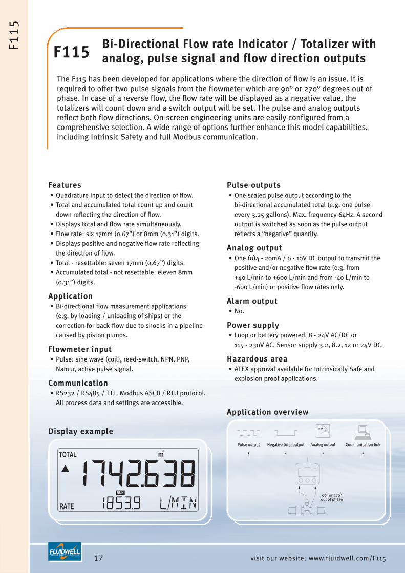
F115 Bi-Directional Flow rate Indicator / Totalizer with analog, pulse signal and flow direction outputs
The F115 has been developed for applications where the direction of flow is an issue. It isrequired to offer two pulse signals from the flowmeter which are 90° or 270° degrees out ofphase. In case of a reverse flow, the flow rate will be displayed as a negative value, thetotalizers will count down and a switch output will be set. The pulse and analog outputsreflect both flow directions. On-screen engineering units are easily configured from acomprehensive selection. A wide range of options further enhance this model capabilities,including Intrinsic Safety and full Modbus communication.
Features• Quadrature input to detect the direction of flow.• Total and accumulated total count up and count
down reflecting the direction of flow.• Displays total and flow rate simultaneously.• Flow rate: six 17mm (0.67”) or 8mm (0.31”) digits.• Displays positive and negative flow rate reflecting
the direction of flow.• Total - resettable: seven 17mm (0.67”) digits.• Accumulated total - not resettable: eleven 8mm
(0.31”) digits.
Application• Bi-directional flow measurement applications
(e.g. by loading / unloading of ships) or thecorrection for back-flow due to shocks in a pipelinecaused by piston pumps.
Flowmeter input• Pulse: sine wave (coil), reed-switch, NPN, PNP,
Namur, active pulse signal.
Communication• RS232 / RS485 / TTL. Modbus ASCII / RTU protocol.
All process data and settings are accessible.
Display example
Pulse outputs• One scaled pulse output according to the
bi-directional accumulated total (e.g. one pulseevery 3.25 gallons). Max. frequency 64Hz. A secondoutput is switched as soon as the pulse outputreflects a “negative” quantity.
Analog output• One (0)4 - 20mA / 0 - 10V DC output to transmit the
positive and/or negative flow rate (e.g. from +40 L/min to +600 L/min and from -40 L/min to -600 L/min) or positive flow rates only.
Alarm output• No.
Power supply• Loop or battery powered, 8 - 24V AC/DC or
115 - 230V AC. Sensor supply 3.2, 8.2, 12 or 24V DC.
Hazardous area• ATEX approval available for Intrinsically Safe and
explosion proof applications.
Application overview

18visit our website: www.fluidwell.com/F117
mA
Analog outputaccording %or flowrate
Communication Link
90° or 270°out of phase
low totalizer alarm output
high totalizeralarm output
external STARTexternal STOP
F11
7
F117 Totalizer Monitor with high / low totalizer alarm and analog output
The F117 has been developed for applications where the totalized quantity has to bemonitored and not the flow rate. When a start command is given, the totalizer is reset to zero.The amount of product measured from that moment is monitored continuously for high totalizervalues. Monitoring for low totalizer values will commence after a stop command is given orafter a pre-defined time. The display shows the preset and actual totalized value, percentageand flow rate. The totalizer alarms are clearly indicated and two outputs are available totransmit alarm conditions. The analog output value mirrors the measured quantity in relationto the preset value. For remote control, an external start and stop input is availble as standard.
Features• The desired totalized (preset) quantity can be set by
the operator• Totalizer monitoring: two alarm values can be set;
low and high totalizer alarm.• Alarm values can be changed by the operator or
they can be password protected.• Displays total and preset value or percentage
simultaneously.• Displays clear alarm messages.• Analog output related to the totalized value or flow
rate.• Quadrature input for bi-directional flow applications.• Total - reset after a start-command:
seven 17mm (0.67”) digits.• Accumulated total - not resettable:
eleven 8mm (0.31”) digits.• Flow rate: seven 17mm (0.67”) digits (shown after
stop command).• LED backlight available.
Application• Automated processes where a minimum and / or a
maximum dispensed quantity has to be monitoredcontinuously.
Display example
Flowmeter input• Pulse: sine wave (coil), reed-switch, NPN, PNP,
Namur, active pulse signal. Status input• External control: start and stop signal.
Analog output• One (0)4 - 20mA / 0 - 10V output to transmit the
flow rate or the totalized quantity in relation to thepreset quantity (e.g. from 0.00 L to 2.50 L).
Alarm outputs• Two alarm outputs for low and high totalizer alarm.
Communication• RS232 / RS485 / TTL. Modbus RTU protocol.
All process data and settings are accessible.
Power supply• Loop or battery powered, 8 - 24V AC/DC or
115 - 230V AC. Sensor supply 3.2, 8.2, 12 or 24V DC.
Hazardous area• ATEX approval available for Intrinsically Safe and
explosion proof applications.
Application overview

19 visit our website: www.fluidwell.com/F118
Analogoutput
Communicationlink
Flowmeterinput
Pulse or alarm output 3
Pulse or alarm output 2
Pulse or alarm output 1
Linearization
F11
8
F118 Flow rate Monitor / Totalizer with linearization, high / low alarm and analog / pulse output
The F118 is a versatile flow rate indicator and totalizer with the ability to precisely linearizethe flowmeter signal. In addition to the average K-Factor or Span, ten linearization points canbe entered with their frequencies or values. The unit will interpolate between these pointsgreatly enhancing accuracy in any flow range. Moreover, continuous flow rate monitoring featureis available with high and low flow rate alarm values and alarm outputs. Flow rate and totalare transmitted with an analog and scaled pulse output. The display shows flow rate, total,accumulated total and alarm messages. On-screen engineering units are easily configured froma comprehensive selection. A wide range of options further enhance this model capabilities.
Features• Ten point linearization of the flow curve - with
interpolation.• Flow rate monitoring: two alarm values can be set:
low and high flow rate alarm.• Alarm values can be changed by the operator or
they can be password protected.• Up to three configurable alarm or scaled pulse
outputs.• Analog output reflecting the flow rate.• Displays total and flow rate simultaneously.• Flow rate: seven 8mm (0.31”) digits.• Total - resettable: seven 17mm (0.67”) digits.• Accumulated total - not resettable: eleven digits.
Application• Liquid flow measurement with flowmeters where a
precise calculation over the full measurement rangeand continuous flow rate monitoring is required.Alternative basic models: F016 and F112.
Flowmeter input• Pulse: sine wave (coil), reed-switch, NPN, PNP,
Namur, active pulse signal. • Analog: (0)4 - 20mA, 0 - 10V DC.
Display example
Pulse outputs• Up to three scaled pulse outputs according to
accumulated total (e.g. one pulse every 3.25gallons). Max. frequency 64Hz.
Analog output• One (0)4 - 20mA / 0 - 10V DC output to transmit the
flow rate. The signal can be scaled to any range (e.g. from 200 L/min to 1200 L/min).
Alarm outputs• Up to three configurable alarm outputs for low, high
or any combination.
Communication• RS232 / RS485 / TTL. Modbus RTU protocol.
All process data and settings are accessible.
Power supply• Loop or battery powered, 8 - 24V AC/DC or
115 - 230V AC. Sensor supply 3.2, 8.2, 12 or 24V DC.
Hazardous area• ATEX approval available for Intrinsically Safe and
explosion proof applications.
Application overview

Introduction This product group offers a unique range of comprehensive solutions to calculate theconsumption and net flow at standard conditions or the ratio between two flows. Typicalapplications are found on board of ships to calculate the fuel consumption, gas flowcalculation in power plants and the monitoring of two component blending or the energyconsumption calculation in cooling or heating applications. All models are available for both safe area and hazardous area applications.
The functionality of these products is based on the F1 hardware platform as multipleinputs are required for flow, temperature and pressure measurement. Following functions are offered:• Ratio (A/B) - model F114.• Sum (A+B) - model F116.• Differential / consumption (A-B) - model F116.• Differential / consumption (A-B) with temperature compensation - model F127.• Liquid volume calculation with temperature compensation - model F126-EL.• Gas volume calculation with temperature and pressure compensation - model F126-EG.• Energy computer with energy consumption calculation - model F128.
A more detailed description of each flow computer and its typical features can be foundon the following pages.
Configuration menuAll configuration settings are accessed via a simple operator menu which can bepassword protected. Each setting is clearly indicated with an alphanumeric description,therefore avoiding confusing abbreviations and baffling codes. There are no sensitive DIP-switches or trimmers, you simply select “flowmeter” as main function, after whichyou can select “NPN pulse” or “span” etc. Once familiar with one F-Series product, youwill be able to program all models in the series without a manual. All settings are safelystored in EEPROM memory.The clear and easy structured configuration menu is one of the most appreciated featuresof the F-Series.
21 visit our website: www.fluidwell.com/flowcomputers
FLOW COMPUTERS

22visit our website: www.fluidwell.com/flowcomputers
FLO
WC
OM
PU
TE
RS
Signal input typeFor the flow computers, four basic signal input typesare available:• Pulse signals for flow measurement: sine wave (coil)
low sensitivity (80mV p-p), sine wave highsensitivity (20mV p-p), Namur, NPN, PNP, reed-switch or active pulses. For most signals a low passfilter can be enabled to ignore pulse bounce. The sine wave input can even be supplied with 10mVor 5mV p-p sensitivity (option ZF and ZG).
• Analog signal: (0)4 - 20mA for flow, temperature andpressure measurement. The input signal can betuned within this range (e.g. from 4.0mA to 18.0mA).To avoid incorrect signal processing at minimumsignal, a low cut-off filter is available.
• Analog signal: 0 - 10V DC for flow, temperature andpressure measurement. The input signal can betuned within this range (e.g. from 2.0 to 5.0V DC). A low cut-off filter is available here too, to avoidcounting at minimum signal.
• PT100: 2 or 3 wire PRTD sensor for temperaturemeasurement.
Data protectionAll settings and totals are stored in EEPROM memoryensuring that no information is lost in the event ofpower failure or battery exchange. To reset total, the CLEAR key must be pressed twice toavoid undesired initialization. Accumulated totalcannot be reset to zero. The configuration menu andalarm values can be password protected to preventunauthorized access.
For an explanation of all the F-Series options such asanalog and alarm outputs, communication, powersupply and enclosures, please read the section“Ordering codes” in the back of this catalog.
Product listingF114 Ratio Monitor / Totalizer with high / low alarms, analog output and communication option.F116 Differential / Sum Flow Computer with analog and pulse outputs and communication option.F126-EL Flow Computer with temperature compensation for corrected liquid volume calculation, analog output
and communication option.F126-EG Flow Computer with temperature and pressure compensation for corrected gas volume calculation, analog
output and communication option.F127-EL Differential Flow Computer with temperature compensation for corrected liquid volume calculation, analog
output and communication option.F128 Energy Computer for closed hot water heating and chilled water cooling systems with analog and pulse
outputs, high / low alarms and communication option.

23 visit our website: www.fluidwell.com/F114
Flowmeter input
Flowmeter input
Alarm output 2Analog output
CommunicationlinkAlarm output 1
F11
4
F114 Ratio Monitor / Totalizer with high / low alarms and analog output
The F114 flow computer calculates the actual ratio between two separate flows. It offers theability to set one low ratio and one high ratio alarm value. Special precautions are taken toallow start-up problems and incorrect ratio readings for a certain period of time. Based on thelocation of the flowmeters, a selection can be made out of six different formulas. The displayshows the ratio, alarm values, flow rate A, total A and flow rate B, total B. On-screenengineering units are easily configured from a comprehensive selection. The ratio can bedisplayed as a percentage or as a ratio. A wide range of options further enhance this modelcapabilities, including Intrinsic Safety and full Modbus communication.
Features• Calculates ratio between flow A and B.• Displays ratio, flow rate A and B, total A and B and
high / low alarm values.• Six ratio calculation formulas.• Ratio monitoring: two alarm values can be set:
low and high ratio alarm.• Alarm values can be changed by the operator or
they can be password protected.• Ratio: seven 17mm (0.67”) digits, displayed as a
percentage or as a ratio.• Flow rate A and B: seven 17mm (0.67”) digits.• Total A and B - resettable: seven 17mm (0.67”)
digits.• LED backlight available.
Application• Mixing or blending of two components where
continuous ratio displaying, monitoring andtotalizing is important. For example in constructionworks, roof or wall insulation, gluing and coating.
Flowmeter input• Pulse: sine wave (coil), reed-switch, NPN, PNP,
Namur, active pulse signal. • Analog: (0)4 - 20mA, 0 - 10V DC.
Display example
Pulse output• No.
Analog output• One (0)4 - 20mA / 0 - 10V DC output to transmit the
ratio, flow rate A or flow rate B. The signal can bescaled to any range (e.g. from 1:5 to 1:100 or from 200 L/min to 1200 L/min).
Alarm outputs• Two alarm outputs: low and high ratio alarm.
Communication• RS232 / RS485 / TTL. Modbus RTU protocol.
All process data and settings are accessible.
Power supply• Loop or battery powered, 8 - 24V AC/DC or
115 - 230V AC. Sensor supply 3.2, 8.2, 12 or 24V DC.
Hazardous area• ATEX approval available for Intrinsically Safe and
explosion proof applications.
Application overview

24visit our website: www.fluidwell.com/F116
mA
Analog output Communication linkNegative pulse outputPulse output
Flowmeter input Flowmeter
input
Flowmeter input
Flowmeter input
SumDifferential
F11
6
F116 Differential / Sum Flow Computerwith analog and pulse outputs
The F116 flow computer has been developed to calculate differential / consumption or totalvolume. The usual difficulties encountered in such applications include: pulsating flows, verylow consumption readings, vibration and high ambient temperatures. These are all wellcatered for in the design and operation of the F116. The pulse and analog outputs reflect thecalculated differential or sum value. On-screen engineering units are easily configured from acomprehensive selection. A wide range of options further enhance this model capabilities,including Intrinsic Safety and full Modbus communication.
Features• Calculates differential flow rate (consumption), total
and accumulated total of flow A and B.• Calculates the sum flow rate, total and accumulated
total of flow A and B.• Precautions for pulsating flows and very low
consumption readings.• Displays total and flow rate simultaneously.• Large digit selection for flow rate or total.• Flow rate: seven 17mm (0.67”) or 8mm (0.31”)
digits.• Total - resettable: seven 17mm (0.67”) digits.• Accumulated total - not resettable: eleven 8mm
(0.31”) digits.
Application• Fuel consumption calculation for diesel engines on
board of ships or locomotives. Sum function: whereflows are split-up in two pipe-lines and total flowhas to be calculated. More advanced model: F127.
Flowmeter input• Pulse: sine wave (coil), reed-switch, NPN, PNP,
Namur, active pulse signal. • Analog: (0)4 - 20mA, 0 - 10V DC.
Display example
Pulse outputs• One scaled pulse output according to accumulated
total (e.g. one pulse every 3.25 gallons). Max. frequency 64Hz. Second output reflects a“negative” differential.
Analog output• One (0)4 - 20mA / 0 - 10V DC output to transmit the
differential or totalized flow rate. The signal can bescaled to any range (e.g. from 200 to 1200 L/min).
Alarm output• No.
Communication• RS232 / RS485 / TTL. Modbus RTU protocol.
All process data and settings are accessible.
Power supply• Loop or battery powered, 8 - 24V AC/DC or
115 - 230V AC. Sensor supply 3.2, 8.2, 12 or 24V DC.
Hazardous area• ATEX approval available for Intrinsically Safe and
explosion proof applications.
Application overview

25 visit our website: www.fluidwell.com/F126el
Analog output Communication link
Flowmeterinput
Temperatureinput
F12
6-E
L
F126-el Flow Computer with temperature compensation for corrected liquid volume
The F126-EL flow computer has been developed to calculate corrected liquid volume at normalconditions. The corrected volumetric flow is calculated by measuring the uncorrectedvolumetric flow and actual line temperature which is processed with the thermal expansioncoefficient algorithm stored in the flow computer. The reference temperature can be definedas desired (e.g. 15°C, 20°C or 60°F). The display shows the compensated flow rate, total,accumulated total and the actual line temperature. A wide range of options further enhancethis model capabilities, including Intrinsic Safety and full Modbus communication.
Features• Calculates compensated flow rate, total and
accumulated total based on a temperature /expansion relationship.
• Displays actual line temperature.• Analog output reflecting compensated flow rate.• Flow rate: seven 8mm (0.31”) digits.• Displays total and flow rate simultaneously.• Temperature: six 17mm (0.67”) digits.• Total - resettable: seven 17mm (0.67”) digits.• Accumulated total - not resettable: eleven digits.• LED backlight available.
Application• Applications where net flow calculation at base
conditions is desired for liquids using the thermalexpansion coefficient.
Flowmeter input• Pulse: sine wave (coil), reed-switch, NPN, PNP,
Namur, active pulse signal. • Analog: (0)4 - 20mA, 0 - 10V DC.Temperature input• PT100 - 2 or 3 wire, (0)4 - 20mA, 0 - 10V DC.
Display example
Pulse output• No.
Analog output• One (0)4 - 20mA / 0 - 10V DC output to transmit the
compensated flow rate. The signal can be scaled toany range (e.g. from 200 L/min to 1200 L/min).
Alarm output• No
Communication• RS232 / RS485 / TTL. Modbus RTU protocol.
All process data and settings are accessible.
Power supply• Loop or battery powered, 8 - 24V AC/DC or
115 - 230V AC. Sensor supply 3.2, 8.2, 12 or 24V DC.
Hazardous area• ATEX approval available for Intrinsically Safe and
explosion proof applications.
Application overview

26visit our website: www.fluidwell.com/F126eg
Analog output Communication link
Flowmeterinput
Temperatureinput
Pressureinput
F12
6-E
G
F126-eg Flow Computer with temperature and pressure compensation for corrected gas volume
The F126-EG flow computer has been developed to calculate corrected gas volume at normalconditions. The corrected volumetric flow is calculated by measuring the uncorrectedvolumetric flow, actual line temperature and pressure which are processed with the equationsstored in the flow computer. A compressibility factor can be set to approach a real gasbehavior. The reference conditions can be defined as desired (e.g. 15°C, 60°F or 1.013 bar).The display shows the compensated flow rate, total, accumulated total and the actual linetemperature and pressure. A wide range of options further enhance this model capabilities,including Intrinsic Safety and full Modbus communication.
Features• Calculates compensated flow rate, total and
accumulated total.• Displays actual line pressure and temperature.• Analog output reflecting compensated flow rate.• Flow rate: seven 8mm (0.31”) digits.• Displays total and flow rate simultaneously.• Temperature: six 17mm (0.67”) digits.• Pressure: six 17mm (0.67”) digits.• Total - resettable: seven 17mm (0.67”) digits.• Accumulated total: eleven 8mm (0.31”) digits.• LED backlight available.
Application• Applications where net gas flow calculation at base
conditions is desired for generic gas products.
Flowmeter input• Pulse: sine wave (coil), reed-switch, NPN, PNP,
Namur, active pulse signal. • Analog: (0)4 - 20mA, 0 - 10V DC.Temperature input• PT100 - 2 or 3 wire, (0)4 - 20mA, 0 - 10V DC.Pressure input• Analog: (0)4 - 20mA, 0 - 10V DC.
Display example
Pulse output• No.
Analog output• One (0)4 - 20mA / 0 - 10V DC output to transmit the
compensated flow rate. The signal can be scaled toany range (e.g. from 200 L/min to 1200 L/min).
Alarm output• No.
Communication• RS232 / RS485 / TTL. Modbus RTU protocol.
All process data and settings are accessible.
Power supply• Loop or battery powered, 8 - 24V AC/DC or
115 - 230V AC. Sensor supply 3.2, 8.2, 12 or 24V DC.
Hazardous area• ATEX approval available for Intrinsically Safe and
explosion proof applications.
Application overview

27 visit our website: www.fluidwell.com/F127
Analog output Communication
Temperatureinput
Flowmeter input
F12
7
F127 Differential Flow Computer with temperaturecompensation for corrected liquid volume
The F127-EL flow computer has been developed to calculate corrected differential liquidvolume at normal conditions. This is calculated by measuring the uncorrected volumetric flowand actual line temperature in both the supply and return line. These signals are processedwith the thermal expansion coefficient algorithm stored in the flow computer. The referencetemperature can be defined as desired (e.g. 15°C, 20°C or 60°F). The usual difficultiesencountered in such applications include: pulsating flows, very low consumption readings,vibration and high ambient temperatures. These are all well catered for in the design andoperation of the F127.
Features• Displays compensated consumption (flow rate),
total and accumulated total.• Supply line: displays actual temperature and
compensated flow rate.• Return line: displays actual temperature and
compensated flow rate.• Flow rate: seven 17mm (0.67”) or 8mm (0.31”)
digits.• Large digit selection for flow rate or total.• Displays total and flow rate simultaneously.• Total - resettable: seven 17mm (0.67”) digits.• Accumulated total: eleven 8mm (0.31”) digits.• Temperature: six 17mm (0.67”) digits.• LED backlight available.
Application• Fuel consumption calculation for diesel engines on
board of ships or locomotives, generators orburners. Alternative basic model: F116.
Flowmeter input• Pulse: sine wave (coil), reed-switch, NPN, PNP,
Namur, active pulse signal. Temperature input• PT100 - 2 or 3 wire, (0)4 - 20mA, 0 - 10V DC.
Display example
Pulse output• No.
Analog output• One (0)4 - 20mA / 0 - 10V DC output to transmit the
compensated differential flow rate (consumption). The signal can be scaled to any range (e.g. from200 L/min to 1200 L/min).
Alarm output• No.
Communication• RS232 / RS485 / TTL. Modbus RTU protocol.
All process data and settings are accessible.
Power supply• Loop or battery powered, 8 - 24V AC/DC or
115 - 230V AC. Sensor supply 3.2, 8.2, 12 or 24V DC.
Hazardous area• ATEX approval available for Intrinsically Safe and
explosion proof applications.
Application overview

28visit our website: www.fluidwell.com/F128
Temperatureinput
Flowmeter input
Analog output
Communicationlink
Alarmoutput 3
Alarmoutput 2
Pulseoutput 1
F12
8
F128 Energy Computer for heating and cooling systems
The F128 energy computer calculates the energy consumption in closed hot water heating andchilled water cooling systems. By measuring the temperature in both the supply and returnline as well as the actual flow, the transferred energy can be calculated using the energyequations stored in the energy computer. The data-logger is able to store actual energyreadings at pre-defined times. Separate energy counters are available to register peak andnon-peak transfers. The display shows the transferred energy, flow rate, temperatures andhigh / low alarm values. A wide range of options further enhance this model capabilities,including Intrinsic Safety and full Modbus communication.
Features• Displays energy, flow rate, temperatures and alarm
values.• Several formulas for heating and/or cooling
applications.• Data-logger for registration per hour, 12 hours, day
or week.• Peak and non-peak registers.• Analog, pulse and alarm outputs available as
standard.• Engineering units for energy, flow rate, total and
temperature on the display. • Operational temperature -30°C to +80°C
(-22°F to 178°F).• LED backlight available.
Application• Energy consumption calculation in heat transfer or
cooling applications.
Flowmeter input• Pulse: sine wave (coil), reed-switch, NPN, PNP,
Namur, active pulse signal. • Analog: (0)4 - 20mA, 0 - 10V DC.Temperature input• PT100 - 2 or 3 wire, (0)4 - 20mA, 0 - 10V DC.
Display example
Pulse output• One scaled pulse output according to the energy
consumption (e.g. one pulse every 1 W). Max. frequency. 64Hz.
Analog output• One (0)4 - 20mA / 0 - 10V output to transmit the
energy consumption, flow rate or temperature. Thesignal can be scaled (e.g. 1 W/min to 100 W/min).
Alarm output• 2 configurable alarm outputs for low or high alarms:
energy consumption, flow rate or temperatures.
Communication• RS232 / RS485 / TTL. Modbus RTU protocol.
All process data and settings are accessible.
Power supply• Loop or battery powered, 8 - 24V AC/DC or
115 - 230V AC. Sensor supply 3.2, 8.2, 12 or 24V DC.
Hazardous area• ATEX approval available for Intrinsically Safe and
explosion proof applications.
Application overview

IntroductionThe F-Series range offers five different batch controllers for the accurate dispensing ofsmall amounts of liquids up to the loading of trucks with two-stage control or analogmulti-stage control. The Delivery Controller is specially designed for the delivery ofunknown quantities of product; it can be used for all kinds of products from gasoline andoil to windshield fluid. All F-Series batch controllers have a self-learning overruncorrection for repeatable results under varying conditions. All models are available forsafe area and hazardous area applications.
The functionality of the batch controllers is based on two main hardware platforms:• F0 platform: these products offer one flowmeter input and one control output for
one-stage control only. This is our basic product range.• F1 platform: these products have one flowmeter input as well as external start / stop
inputs, multiple outputs for two-stage control or scaled pulse output, analog outputand communication option. This is our advanced product range.
Both platforms share the same technology, enclosures, display and options but arededicated to their typical functionality.
Common Batch Controller features• Clear operator information is a key feature of these products. Essential information is
displayed as a clear text (e.g. “press stop”) and not as mysterious abbreviations. • The dedicated display shows two lines of information simultaneously along with its
function like “preset” and “actual” or “accumulated total” so the operator understandsthe displayed information.
• The preset value and the actual value during the batch process is displayed with seven17mm (0.67”) and seven 8mm (0.31”) high digits with their engineering unit. The following units can be selected through software: ml, L, m3, GAL, USGAL, kg, lb, bblor no unit.
• Entering the preset value is a basic function, understandable for every operator. For repeatable batches it is not required to re-enter the preset value, simply press start.
29 visit our website: www.fluidwell.com/batchcontrollers
BATCH CONTROLLERS

• During batching, the displayed actual value cancount up to display the batched quantity or countdown to display the remaining quantity.
• The active self learning overrun correctioncompensates the slowness of the control valve aswell as unstable line pressure due to a decreasingstock level; a repeating and accurate batch quantityis the result.
• A resettable totalizer is displayed with seven 17mm(0.67”) high digits.
• A non-resettable accumulated total is displayed witheleven 8mm (0.31”) digits and uses the samemeasuring unit as total and preset value.
• With the maximum preset value, the operator can beprotected against incorrect entry of a batch size.
Further product specific features are found on thefollowing pages.
Configuration menuAll configuration settings are accessed via a simpleoperator menu which can be password protected. Each setting is clearly indicated with an alphanumericdescription, therefore avoiding confusing abbreviationsand baffling codes. There are no sensitive DIP-switchesor trimmers, you simply select “Flowmeter” as mainfunction, after which you can select “NPN pulse” or“span” etc. Once familiar with one F-Series product,you will be able to program all models in the serieswithout a manual. All settings are safely stored inEEPROM memory. The clear and easy structuredconfiguration menu is one of the most appreciatedfeatures of the F-Series.
Signal input typeFor the batch controllers, three basic signal inputtypes are available:• Pulse signals: sine wave (coil) low sensitivity (80mV
p-p), sine wave high sensitivity (20mV p-p), Namur,NPN, PNP, reed-switch or active pulses. For mostsignals a low pass filter can be enabled to ignorepulse bounce. The sine wave input can even besupplied with 10mV or 5mV p-p sensitivity (option ZFand ZG).
• Analog signal: (0)4 - 20mA or 4 - 20mA input looppowered version. The input signal can be tunedwithin this range (e.g. from 4.0mA to 18.0mA). To avoid counting at minimum signal, a low cut-offfilter is available.
• Analog signal: 0 - 10V DC. The input signal can betuned within this range (e.g. from 2.0 to 5.0V DC). A low cut-off filter is available here too, to avoidcounting at minimum signal.
Data protectionAll settings and totals are stored in EEPROM memoryensuring that no information is lost in the event ofpower failure or battery exchange. To reset total, the program key and stop key must bepressed before resetting to zero to avoid undesiredinitialization. Accumulated cannot be reset to zero. The configuration menu can be password protected toprevent unauthorized access.For an explanation of all the F-Series options such asanalog and control outputs, communication, powersupply and enclosures, please read the section“Ordering codes” in the back of this catalog.
30visit our website: www.fluidwell.com/batchcontrollers
BA
TCH
CO
NT
RO
LLE
RS
Product listingF030 Batch Controller with one control output (one-stage control).F130 Batch Controller with two-stage control or one-stage control with a scaled pulse output, external start and
stop inputs and communication option.F131 Batch Controller with analog output reflecting the flow rate, two-stage control or one-stage control with a
scaled pulse output, external start and stop inputs and communication option.F133 Delivery Controller with pump start, valve control and other features for e.g. fuel dispensing.F134 Batch Controller with analog output for smooth multi-stage valve control, pump start and non-drip valve
control, external start and stop inputs and communication option.F136 Batch Controller with analog output related to the process stage, two-stage control or one-stage control with
a scaled pulse output, external start and stop inputs and communication option.

31 visit our website: www.fluidwell.com/F030
Flowmeterinput
Control output
F03
0
F030 Batch Controller with one-stage control
The F030 is a straight forward but easy-to-use batch controller. The operator can easily entera batch quantity or execute repeating batches. During the batch, the preset value is displayedas well as the batched or remaining quantity. The automatic self-learning overrun correctionwill ensure an accurate batch every time again. On-screen engineering units are easilyconfigured from a comprehensive selection. A wide range of options further enhance thismodel capabilities, including Intrinsic Safety.
Features• Large display shows preset value and running batch
value simultaneously.• Self-learning overrun correction.• One control output to drive a valve or pump.• Easy operation to enter a batch value and to control
the process.• Count-up and count-down function available.• Green/amber LED backlight with adjustable intensity.• Actual batched quantity: seven 17mm (0.67”) digits.• Preset value: seven 17mm (0.67”) digits during
programming and 8mm (0.31”) digits duringprocess.
• Total - resettable: seven 17mm (0.67”) digits.• Accumulated total - not resettable: eleven digits.• Auto backup of settings and running totals in
EEPROM memory.
Application• For one-stage batch applications at low or medium
flow rates. Alternative more advanced models: F130,F131, F134, F136 and 300-Series.
Communication• No.
Display example
Flowmeter input• Pulse: sine wave (coil), reed-switch, NPN, PNP,
Namur, active signal. • Analog: (0)4 - 20mA, 0 - 10V DC.Status input• No.
Pulse output• No.
Analog output• No.
Control output• One control output for one-stage batching.
Power supply• Loop or battery powered, 8 - 24V AC/DC or
115 - 230V AC. Sensor supply 3.2, 8.2, 12 or 24V DC.
Hazardous area• ATEX, IECEx, CSA and FM approvals available for
Intrinsically Safe and non-incendive applications.• ATEX approval available for explosion proof
enclosure.
Application overview

32visit our website: www.fluidwell.com/F130
Pulse output R2(with 1-stage control only) Communication link
Flowmeterinput
External STARTExternal PAUSE / STOP
Control output R1 Control output R2
F13
0
F130 Batch Controller with two-stage control / pulse output
The F130 is a batch controller with two control outputs for two-stage batching or one-stagecontrol with a scaled pulse output. The operator can enter a batch quantity easily or executerepeating batches. During the batch, the preset value is displayed simultaneously with thebatched or remaining quantity. The automatic self-learning overrun correction will ensure anaccurate result each batch again. A no-flow monitoring feature is available to detect a missingflow meter signal during batching. On-screen engineering units are easily configured from acomprehensive selection. A wide range of options further enhance this model capabilities,including Intrinsic Safety and full Modbus communication.
Features• Large display shows preset value and running batch
value simultaneously.• Self-learning overrun correction.• Two-stage control for batching at high flow rates.• Count-up and count-down function available.• Scaled pulse output.• Actual batched quantity: seven 17mm (0.67”) digits.• Preset value: seven digits.• No-flow monitoring.• Total - resettable: seven 17mm (0.67”) digits.• Accumulated total - not resettable: eleven digits.
Application• For batching at low, medium or high flow rates with
two-stage control. Alternative basic model: F030 ormore advanced models: F131, F134, F136 and 300-Series.
Flowmeter input• Pulse: sine wave (coil), reed-switch, NPN, PNP,
Namur, active pulse signal. • Analog: (0)4 - 20mA, 0 - 10V DC.Status input• External control: start / pause / stop.
Display example
Pulse output• Scaled pulse output according to accumulated or
batched total (e.g. one pulse every 3.25 gallons).Max. frequency: 64Hz.
Analog output• No.
Control outputs• Two outputs for one or two-stage batching.
Note: with two-stage control no pulse outputavailable.
Communication• RS232 / RS485 / TTL. Modbus ASCII / RTU protocol.
All process data and settings can be read andmodified as well as a batch can be started / stopped.
Power supply• Loop or battery powered, 8 - 24V AC/DC or
115 - 230V AC. Sensor supply 3.2, 8.2, 12 or 24V DC.
Hazardous area• ATEX approval available for Intrinsically Safe and
explosion proof applications.
Application overview
33 visit our website: www.fluidwell.com/F131
Pulse output R2(with 1-stage control only) Communication link
Flowmeterinput
External STARTExternal PAUSE / STOP
Control output R1 Control output R2
Analog output
F13
1
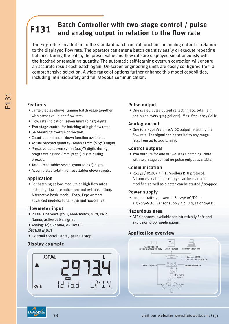
F131 Batch Controller with two-stage control / pulse and analog output in relation to the flow rate
The F131 offers in addition to the standard batch control functions an analog output in relationto the displayed flow rate. The operator can enter a batch quantity easily or execute repeatingbatches. During the batch, the preset value and flow rate are displayed simultaneously withthe batched or remaining quantity. The automatic self-learning overrun correction will ensurean accurate result each batch again. On-screen engineering units are easily configured from acomprehensive selection. A wide range of options further enhance this model capabilities,including Intrinsic Safety and full Modbus communication.
Features• Large display shows running batch value together
with preset value and flow rate.• Flow rate indication: seven 8mm (0.31”) digits.• Two-stage control for batching at high flow rates.• Self-learning overrun correction.• Count-up and count-down function available.• Actual batched quantity: seven 17mm (0.67”) digits.• Preset value: seven 17mm (0.67”) digits during
programming and 8mm (0.31”) digits duringprocess.
• Total - resettable: seven 17mm (0.67”) digits.• Accumulated total - not resettable: eleven digits.
Application• For batching at low, medium or high flow rates
including flow rate indication and re-transmitting.Alternative basic model: F030, F130 or moreadvanced models: F134, F136 and 300-Series.
Flowmeter input• Pulse: sine wave (coil), reed-switch, NPN, PNP,
Namur, active pulse signal. • Analog: (0)4 - 20mA, 0 - 10V DC.Status input• External control: start / pause / stop.
Display example
Pulse output• One scaled pulse output reflecting acc. total (e.g.
one pulse every 3.25 gallons). Max. frequency 64Hz.
Analog output• One (0)4 - 20mA / 0 - 10V DC output reflecting the
flow rate. The signal can be scaled to any range (e.g. from 20 to 200 L/min).
Control outputs• Two outputs for one or two-stage batching. Note:
with two-stage control no pulse output available.
Communication• RS232 / RS485 / TTL. Modbus RTU protocol.
All process data and settings can be read andmodified as well as a batch can be started / stopped.
Power supply• Loop or battery powered, 8 - 24V AC/DC or
115 - 230V AC. Sensor supply 3.2, 8.2, 12 or 24V DC.
Hazardous area• ATEX approval available for Intrinsically Safe and
explosion proof applications.
Application overview
34visit our website: www.fluidwell.com/F133
external START or CONTINUOUS signal
Communication link
external PAUSE / STOP
Flowmeterinput
Controloutput R2
Controloutput R1
F13
3
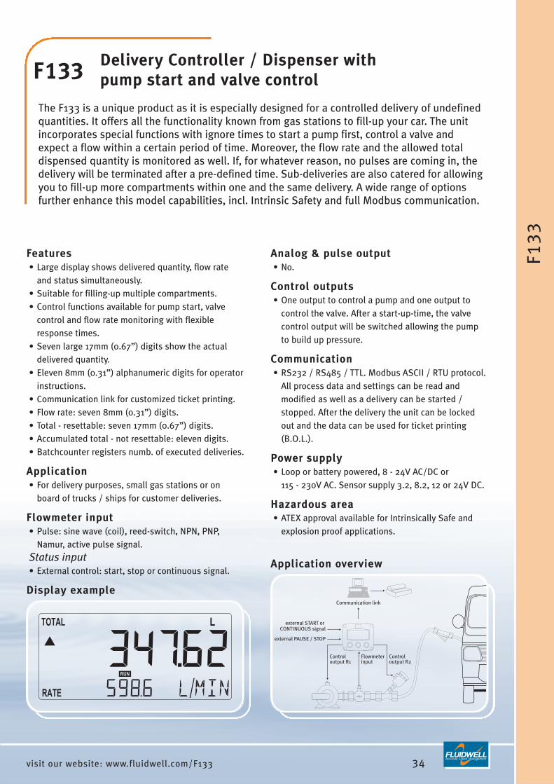
F133 Delivery Controller / Dispenser with pump start and valve control
The F133 is a unique product as it is especially designed for a controlled delivery of undefinedquantities. It offers all the functionality known from gas stations to fill-up your car. The unitincorporates special functions with ignore times to start a pump first, control a valve andexpect a flow within a certain period of time. Moreover, the flow rate and the allowed totaldispensed quantity is monitored as well. If, for whatever reason, no pulses are coming in, thedelivery will be terminated after a pre-defined time. Sub-deliveries are also catered for allowingyou to fill-up more compartments within one and the same delivery. A wide range of optionsfurther enhance this model capabilities, incl. Intrinsic Safety and full Modbus communication.
Features• Large display shows delivered quantity, flow rate
and status simultaneously.• Suitable for filling-up multiple compartments.• Control functions available for pump start, valve
control and flow rate monitoring with flexibleresponse times.
• Seven large 17mm (0.67”) digits show the actualdelivered quantity.
• Eleven 8mm (0.31”) alphanumeric digits for operatorinstructions.
• Communication link for customized ticket printing.• Flow rate: seven 8mm (0.31”) digits.• Total - resettable: seven 17mm (0.67”) digits.• Accumulated total - not resettable: eleven digits.• Batchcounter registers numb. of executed deliveries.
Application• For delivery purposes, small gas stations or on
board of trucks / ships for customer deliveries.
Flowmeter input• Pulse: sine wave (coil), reed-switch, NPN, PNP,
Namur, active pulse signal. Status input• External control: start, stop or continuous signal.
Display example
Analog & pulse output• No.
Control outputs• One output to control a pump and one output to
control the valve. After a start-up-time, the valvecontrol output will be switched allowing the pumpto build up pressure.
Communication• RS232 / RS485 / TTL. Modbus ASCII / RTU protocol.
All process data and settings can be read andmodified as well as a delivery can be started /stopped. After the delivery the unit can be lockedout and the data can be used for ticket printing(B.O.L.).
Power supply• Loop or battery powered, 8 - 24V AC/DC or
115 - 230V AC. Sensor supply 3.2, 8.2, 12 or 24V DC.
Hazardous area• ATEX approval available for Intrinsically Safe and
explosion proof applications.
Application overview
36visit our website: www.fluidwell.com/F136
Pulse output R2(with 1-stage control only) Communication link
Flowmeterinput
External STARTExternal PAUSE / STOP
Control output R1 Control output R2
Analog output
F13
6
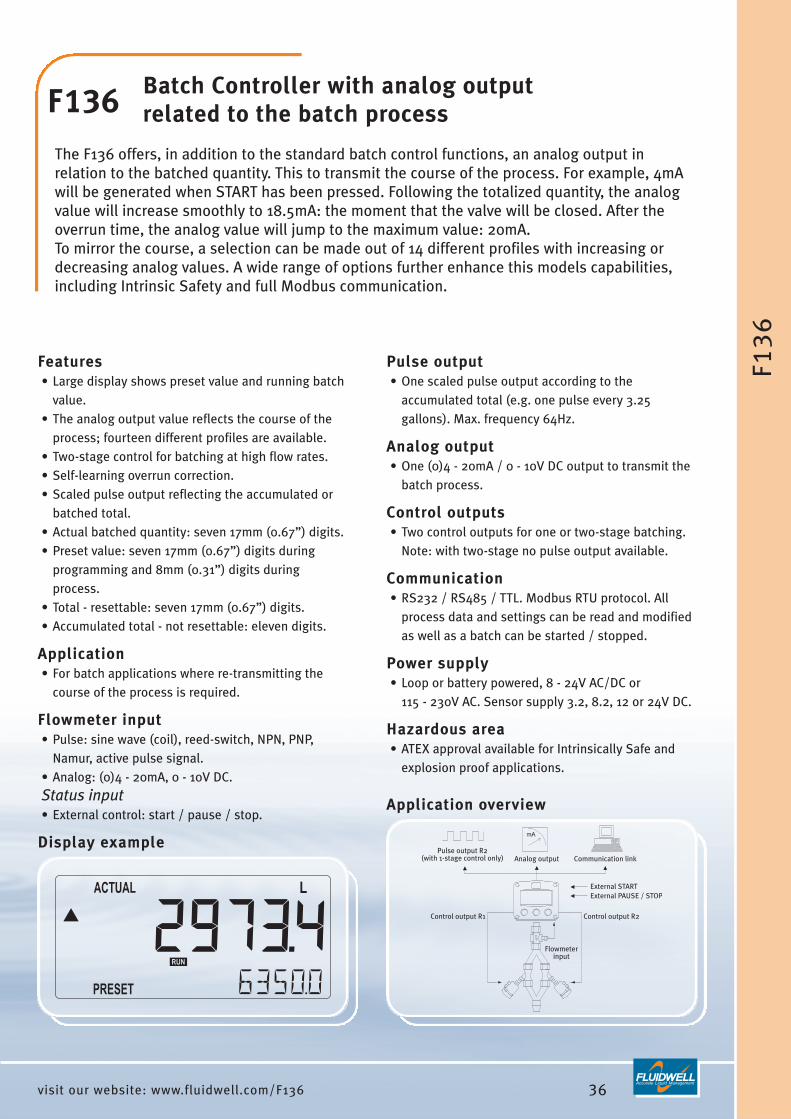
F136 Batch Controller with analog outputrelated to the batch process
The F136 offers, in addition to the standard batch control functions, an analog output inrelation to the batched quantity. This to transmit the course of the process. For example, 4mAwill be generated when START has been pressed. Following the totalized quantity, the analogvalue will increase smoothly to 18.5mA: the moment that the valve will be closed. After theoverrun time, the analog value will jump to the maximum value: 20mA. To mirror the course, a selection can be made out of 14 different profiles with increasing ordecreasing analog values. A wide range of options further enhance this models capabilities,including Intrinsic Safety and full Modbus communication.
Features• Large display shows preset value and running batch
value.• The analog output value reflects the course of the
process; fourteen different profiles are available.• Two-stage control for batching at high flow rates.• Self-learning overrun correction.• Scaled pulse output reflecting the accumulated or
batched total.• Actual batched quantity: seven 17mm (0.67”) digits.• Preset value: seven 17mm (0.67”) digits during
programming and 8mm (0.31”) digits duringprocess.
• Total - resettable: seven 17mm (0.67”) digits.• Accumulated total - not resettable: eleven digits.
Application• For batch applications where re-transmitting the
course of the process is required.
Flowmeter input• Pulse: sine wave (coil), reed-switch, NPN, PNP,
Namur, active pulse signal. • Analog: (0)4 - 20mA, 0 - 10V DC.Status input• External control: start / pause / stop.
Display example
Pulse output• One scaled pulse output according to the
accumulated total (e.g. one pulse every 3.25gallons). Max. frequency 64Hz.
Analog output• One (0)4 - 20mA / 0 - 10V DC output to transmit the
batch process.
Control outputs• Two control outputs for one or two-stage batching.
Note: with two-stage no pulse output available.
Communication• RS232 / RS485 / TTL. Modbus RTU protocol. All
process data and settings can be read and modifiedas well as a batch can be started / stopped.
Power supply• Loop or battery powered, 8 - 24V AC/DC or
115 - 230V AC. Sensor supply 3.2, 8.2, 12 or 24V DC.
Hazardous area• ATEX approval available for Intrinsically Safe and
explosion proof applications.
Application overview

Introduction This product group offers several solutions from a basic temperature indicator up to a fulltemperature monitor with signal re-transmitting, high / low temperature monitoring, fouralarm outputs as well as full Modbus communication. All models are available for safearea and hazardous area applications. Moreover, wireless data transmission and remotetemperature monitoring is offered with our M-Series and ProcessMonitor.com productsand services.
The functionality of these products is based on two main hardware platforms:• F0 platform: these products offer one signal input and can have one alarm output.
This is our basic product range.• F1 platform: these products have one or more signal inputs, multiple outputs and
communication option. This is our advanced product range.Both platforms share the same technology, enclosures, display and options but arededicated to their typical functionality.
Common Temperature Indicator features• Clear operator information is a key feature of these products. Essential information is
displayed as a clear text (e.g. “alarm: low temp”). • The dedicated display shows two lines of information at the same time, so the actual
temperature is displayed simultaneously with the measuring unit or alarm message.• The actual temperature is displayed with six 17mm (0.67”) high digits or even with
26mm (1”) high digits (F040).• The measuring unit is displayed with 8mm (0.31”) digits. The following units can be
selected through software: °C, °F, K or no unit.Further product specific features are found on the following pages.
37 visit our website: www.fluidwell.com/temperature
TEMPERATURE INDICATORS,MONITORS AND TRANSMITTERS

Configuration menuAll configuration settings are accessed via a simpleoperator menu which can be password protected. Each setting is clearly indicated with an alphanumericdescription, therefore avoiding confusing abbreviationsand baffling codes. There are no sensitive DIP-switchesor trimmers, you simply select “Sensor” as mainfunction, after which you can select “span” or “offset”etc. Once familiar with one F-Series product, you willbe able to program all models in the series without amanual. All settings are safely stored in EEPROMmemory. The clear and easy structured configurationmenu is one of the most appreciated features of the F-Series.
Signal input typeFor the temperature indicators, four basic signal inputtypes are available:• Analog signal: (0)4 - 20mA or 4 - 20mA input loop
powered version. The input signal can be tunedwithin this range (e.g. from 4.0mA to 18.0mA). To avoid signal processing at minimum signal, a lowcut-off filter is available.
• Analog signal: 0 - 10V DC. The input signal can betuned within this range (e.g. from 2.0 to 5.0V DC). A low cut-off filter is available here too.
• PT100: 2, 3 or 4 wire PRTD sensor. • Thermocouple (F0-Series only). Further, a digital filter can be set to a desired value tostabilize the temperature measurement reading. Theoffset function allows the indicator to be operationalwithin any desired range (e.g. from -80°F to 640°F).
Data protectionAll settings are stored in EEPROM memory ensuringthat information is not lost in the event of powerfailure or battery exchange. The configuration menuand alarm values can be password protected toprevent unauthorized access.
For an explanation of all the F-Series options such asanalog and alarm outputs, communication, powersupply and enclosures, please read the section“Ordering codes” in the back of this catalog.
38visit our website: www.fluidwell.com/temperature
TEM
PE
RA
TU
RE
IND
ICA
TOR
S
Product listingF040 Temperature Indicator.F043 Temperature Monitor with two high / low alarm values and one alarm output.F141 Dual Input Temperature Indicator in one enclosure with communication option.F143 Temperature Monitor with four high / low alarm values, max. four alarm outputs, analog output and
communication option.

39 visit our website: www.fluidwell.com/F040
Temperatureinput
F04
0
F040 Temperature Indicatorwith very large digits
The F040 is a straight forward temperature indicator with large 26mm (1”) high digits. The measuring unit to be displayed below the temperature is simply selected through analphanumeric configuration menu. No adhesive labels have to be put on the outside of theenclosure: a weather proof and user-friendly solution! The configuration of the Span, off-setand number of decimals is done through software functions, without any sensitive DIP-switches or trimmers. A wide range of options further enhance this model capabilities,including Intrinsic Safety for hazardous area applications.
Features• Displays actual temperature and measuring unit.• Very large 26mm (1”) high digits for temperature.• Piegraph indication: ten segments.• Selectable on-screen engineering units: °C, °F or K.• Number of digits for temperature: 51/2.• Green/amber LED backlight with adjustable intensity.• Auto backup of settings in EEPROM memory.• Operational temperature -40°C to +80°C
(-40°F to 178°F).• Easy configuration with clear alphanumeric display.• Very compact design for panel mount, wall mount or
field mount applications.• Rugged aluminum or polyamide field mount
enclosure IP67 / NEMA 4X.
Applications• Applications where a basic temperature
measurement display is required withouttemperature monitoring or signal re-transmitting.More advanced models: F043, F141 and F143.
Display example
Temperature input• PT100 - 2, 3 or 4 wire.• Analog: (0)4 - 20mA, 0 - 10V DC.• Thermocouple.
Analog output• No.
Alarm output• No.
Communication• No.
Power supply• Loop or battery powered, 8 - 24V AC/DC or
115 - 230V AC. Sensor supply 8.2, 12 or 24V DC.
Hazardous area• ATEX, IECEx, CSA and FM approvals available for
Intrinsically Safe and non-incendive applications.• ATEX approval available for explosion proof
enclosure.
Application overview

40visit our website: www.fluidwell.com/F043
Alarm output
Temperatureinput
F04
3
F043 Temperature Monitorwith one high / low alarm output
The F043 is a versatile temperature indicator with continuous temperature monitoring feature.It offers the ability to set one low temperature and one high temperature alarm value. If desired, an alarm ignore function can be set up to allow for an incorrect temperature for acertain period of time. The configuration of the Span, off-set and number of decimals is donethrough software functions, without any sensitive DIP-switches or trimmers. The displayshows the actual temperature, alarm values, alarm messages and status. On-screenengineering units are easily configured from a comprehensive selection. A wide range ofoptions further enhance this model capabilities, including Intrinsic Safety.
Features• Temperature monitoring: two alarm values can be
set: low and high temperature alarm.• Alarm values can be changed by the operator or
they can be password protected.• One alarm output for high, low or both alarms.• Temperature: six large 17mm (0.67”) digits.• Selectable on-screen engineering units: °C, °F or K.• Red flashing LED backlight in case of a temperature
alarm; intensity adjustable.• Displays clear alarm messages.• Auto backup of settings in EEPROM memory.• Operational temperature -40°C to +80°C
(-40°F to 178°F).
Applications• For applications where continuous temperature
measurement and monitoring is important withoutsignal re-transmitting. Alternative basic model:F040, F141 or more advanced model F143.
Display example
Temperature input• PT100 - 2, 3 or 4 wire.• Analog: (0)4 - 20mA, 0 - 10V DC.• Thermocouple.
Analog output• No.
Alarm output• One configurable alarm output for high, low or both
temperature alarms.
Communication• No.
Power supply• Loop or battery powered, 8 - 24V AC/DC or
115 - 230V AC. Sensor supply 8.2, 12 or 24V DC.
Hazardous area• ATEX, IECEx, CSA and FM approvals available for
Intrinsically Safe and non-incendive applications.• ATEX approval available for explosion proof
enclosure.
Application overview

41 visit our website: www.fluidwell.com/F141
Communication link
Temperatureinput
Temperatureinput
F14
1
F141 Dual Input Temperature Indicator
The F141 incorporates two temperature indicators in one enclosure. There is no relationshipbetween the inputs, even different measuring units can be used. The measuring unit isdisplayed together with the input channel information A or B. The F141 can be set to show theselected information manually or with an automatic toggle function. A wide range of optionsis available to further enhance this model capabilities, including Intrinsic Safety and fullModbus communication.
Features• Two temperature indicators.• Displays actual temperature, measuring unit and
product I.D. simultaneously.• Temperature: six 17mm (0.67”) digits.• Separate engineering units for each input.• Backup of settings in EEPROM memory.• Operational temperature -30°C to +80°C
(-22°F to 178°F).• Very compact design for panel mount, wall mount or
field mount applications.• Rugged aluminum or polyamide field mount
enclosure IP67 / NEMA 4X.• LED backlight available.
Application• For applications where two indicators are required
but one single and compact enclosure is desired.Alternative basic model: two separate F040s.
Temperature input• PT100 - 2 or 3 wire.• Analog: (0)4 - 20mA, 0 - 10V DC.
Display example
Analog output• No.
Alarm outputs• No.
Communication• RS232 / RS485 / TTL. Modbus ASCII / RTU protocol.
All process data and settings are accessible.
Power supply• Loop or battery powered, 8 - 24V AC/DC or
115 - 230V AC. Sensor supply 8.2, 12 or 24V DC.
Hazardous area• ATEX approval available for Intrinsically Safe and
explosion proof applications.
Application overview

42visit our website: www.fluidwell.com/F143
Alarmoutput 4
Analogoutput
Communicationlink
Temperatureinput
Alarmoutput 3
Alarmoutput 2
Alarmoutput 1
F14
3
F143 Temperature Monitor with analogand high / low alarm outputs
The F143 is a versatile temperature indicator with continuous temperature monitoring feature.It offers the ability to set two low temperature and two high temperature alarm values. Alarm ignore function allows an incorrect temperature for a certain period of time. Up to fiveoutputs are available to transmit the alarm condition and actual temperature. The displayshows the actual temperature, alarm values, alarm messages and status. On-screenengineering units are easily configured from a comprehensive selection. A wide range ofoptions further enhance this model capabilities, including Intrinsic Safety and full Modbuscommunication.
Features• Temperature monitoring: four alarm values can be
set: low-low, low, high and high-high temperaturealarm.
• Alarm values can be changed by the operator orthey can be password protected.
• Analog output to transmit the actual temperature.• Up to four configurable alarm outputs.• Displays temperature, measuring unit and alarm
messages simultaneously.• Temperature and alarm values: six large 17mm
(0.67”) digits.• Alarm ignore function allows an incorrect
temperature for a certain period of time.• Selectable on-screen engineering units °C, °F or K.
Application• Temperature measurement where continuous
temperature monitoring and re-transmitting isimportant, or serial communication is required.Alternative basic model: F040 or F043.
Temperature input• PT100 - 2, 3 or 4 wire.• Analog: (0)4 - 20mA, 0 - 10V DC.
Display example
Analog output• One (0)4 - 20mA / 0 - 10V DC output to transmit the
temperature. The signal can be scaled to any range(e.g. from -20°C to +200°C).
Alarm outputs• Up to four configurable alarm outputs for low-low,
low, high, high-high or any combination.
Communication• RS232 / RS485 / TTL. Modbus ASCII / RTU protocol.
All process data and settings are accessible.
Power supply• Loop or battery powered, 8 - 24V AC/DC or
115 - 230V AC. Sensor supply 8.2, 12 or 24V DC.
Hazardous area• ATEX approval available for Intrinsically Safe and
explosion proof applications.
Application overview

IntroductionThis product group offers several solutions from a basic pressure indicator up to a fullpressure monitor with signal re-transmitting, high / low pressure monitoring, four alarmoutputs as well as full Modbus communication. All being available for both safe area andhazardous area applications. Moreover, wireless data re-transmitting and remotepressure monitoring is offered with our M-series and ProcessMonitor.com products andservices.
The functionality of these products is based on two main hardware platforms:• F0 platform: these products offer one signal input and can have one alarm output.
This is our basic product range.• F1 platform: these products have one or more signal inputs, multiple outputs and
communication option. This is our advanced product range.Both platforms share the same technology, enclosures, display and options but arededicated to their typical functionality.
Common Pressure Indicator features• Clear operator information is a key feature of these products. Essential information is
displayed as a clear text (e.g. “low pressure”) and not as mysterious abbreviations. • The dedicated display shows two lines of information at the same time, so the actual
pressure is displayed simultaneously with the measuring unit or alarm message.• The actual pressure is displayed with six 17mm (0.67”) high digits or even with 26mm
(1”) high digits (F050).• The measuring unit is displayed with 8mm (0.31”) digits. The following units can be
selected through software: mbar, bar, psi or no unit.Further product specific features are found on the following pages.
43 visit our website: www.fluidwell.com/pressure
PRESSURE INDICATORS, MONITORS AND TRANSMITTERS

Configuration menuAll configuration settings are accessed via a simpleoperator menu which can be password protected. Each setting is clearly indicated with an alphanumericdescription, therefore avoiding confusing abbreviationsand baffling codes. There are no sensitive DIP-switchesor trimmers, you simply select “Sensor” as mainfunction, after which you can select “span” or “offset”etc. Once familiar with one F-Series product, you willbe able to program all models in the series without amanual. All settings are safely stored in EEPROMmemory. The clear and easy structured configurationmenu is one of the most appreciated features of the F-Series.
Signal input typeFor the pressure indicators, two basic signal inputtypes are available:• Analog signal: (0)4 - 20mA or 4 - 20mA input loop
powered version. The input signal can be tunedwithin this range (e.g. from 4.0mA to 18.0mA). To avoid signal processing at minimum signal, a lowcut-off filter is available.
• Analog signal: 0 - 10V DC. The input signal can betuned within this range (e.g. from 2.0 to 5.0V DC). A low cut-off filter is available here too, to avoidcounting at minimum signal.
Further, a digital filter can be set to a desired value tostabilize the pressure measurement reading. The offsetfunction allows the indicator to be operational withinany desired range (e.g. from 10 bar to 100 bar).
Data protectionAll settings are stored in EEPROM memory ensuringthat information is not lost in the event of powerfailure or battery exchange. The configuration menuand alarm values can be password protected toprevent unauthorized access.
For an explanation of all the F-Series options such asanalog and alarm outputs, communication, powersupply and enclosures, please read the section“Ordering codes” in the back of this catalog.
44visit our website: www.fluidwell.com/pressure
PR
ES
SU
RE
IND
ICA
TOR
S
Product listingF050 Pressure Indicator.F053 Pressure Monitor with two high / low alarm values and one alarm output.F151 Dual Input Pressure Indicator in one enclosure with communication option.F153 Pressure Monitor with four high / low alarm values, max. four alarm outputs, analog output and
communication option.

45 visit our website: www.fluidwell.com/F050
Pressureinput
F05
0
F050 Pressure Indicatorwith very large digits
The F050 is a straight forward pressure indicator with large 26mm (1”) high digits. The measuring unit to be displayed below the pressure is simply selected through an alphanumeric configuration menu. No adhesive labels have to be put on the outside of theenclosure: a weather proof and user-friendly solution! The configuration of the Span, off-setand number of decimals is done through software functions, without any sensitive DIP-switches or trimmers. A wide range of options further enhance this model capabilities,including Intrinsic Safety for hazardous area applications.
Features• Displays actual pressure and measuring unit.• Very large 26mm (1”) high digits for pressure.• Piegraph indication: ten segments.• Selectable on-screen engineering units: mBar, Bar
or PSI.• Number of digits for pressure: 51/2.• Green/amber LED backlight with adjustable intensity.• Auto backup of settings in EEPROM memory.• Operational temperature -40°C to +80°C
(-40°F to 178°F).• Easy configuration with clear alphanumeric display.• Very compact design for panel mount, wall mount or
field mount applications.• Rugged aluminum or polyamide field mount
enclosure IP67 / NEMA 4X.
Applications• Applications where a basic pressure measurement
display is required without pressure monitoring orsignal re-transmitting. More advanced models:F053, F151 and F153.
Display example
Pressure input• Analog: (0)4 - 20mA, 0 - 10V DC.
Analog output• No.
Alarm output• No.
Communication• No.
Power supply• Loop or battery powered, 8 - 24V AC/DC or
115 - 230V AC. Sensor supply 8.2, 12 or 24V DC.
Hazardous area• ATEX, IECEx, CSA and FM approvals available for
Intrinsically Safe and non-incendive applications.• ATEX approval available for explosion proof
enclosure.
Application overview

46visit our website: www.fluidwell.com/F053
Pressureinput
Alarm output
F05
3
F053 Pressure Monitor with one high / low alarm output
The F053 is a versatile pressure indicator with continuous pressure monitoring feature. It offers the ability to set one low pressure and one high pressure alarm value. If desired, analarm ignore function can be set up to allow for an incorrect pressure for a certain period oftime. The configuration of the Span, off-set and number of decimals is done through softwarefunctions, without any sensitive DIP-switches or trimmers. The display shows the actualpressure, alarm values, alarm messages and status. On-screen engineering units are easilyconfigured from a comprehensive selection. A wide range of options further enhance thismodel capabilities, including Intrinsic Safety.
Features• Pressure monitoring: two alarm values can be set:
low and high pressure alarm.• Alarm values can be changed by the operator or
they can be password protected.• One alarm output for high, low or both pressure
alarms.• Pressure: six large 17mm (0.67”) digits.• Selectable on-screen engineering units: mBar, Bar,
PSI.• Red flashing LED backlight in case of a pressure
alarm; intensity adjustable.• Displays clear alarm messages.• Auto backup of settings in EEPROM memory.• Operational temperature -40°C to +80°C
(-40°F to 178°F).• Very compact design for panel mount, wall mount or
field mount applications.
Applications• For applications where continuous pressure
measurement and monitoring is important withoutsignal re-transmitting. Alternative basic model: F050or more advanced models F151 and F153.
Display example
Pressure input• Analog: (0)4 - 20mA, 0 - 10V DC.
Analog output• No.
Alarm output• One configurable alarm output for high, low or both
pressure alarms.
Communication• No.
Power supply• Loop or battery powered, 8 - 24V AC/DC or
115 - 230V AC. Sensor supply 8.2, 12 or 24V DC.
Hazardous area• ATEX, IECEx, CSA and FM approvals available for
Intrinsically Safe and non-incendive applications.• ATEX approval available for explosion proof
enclosure.
Application overview
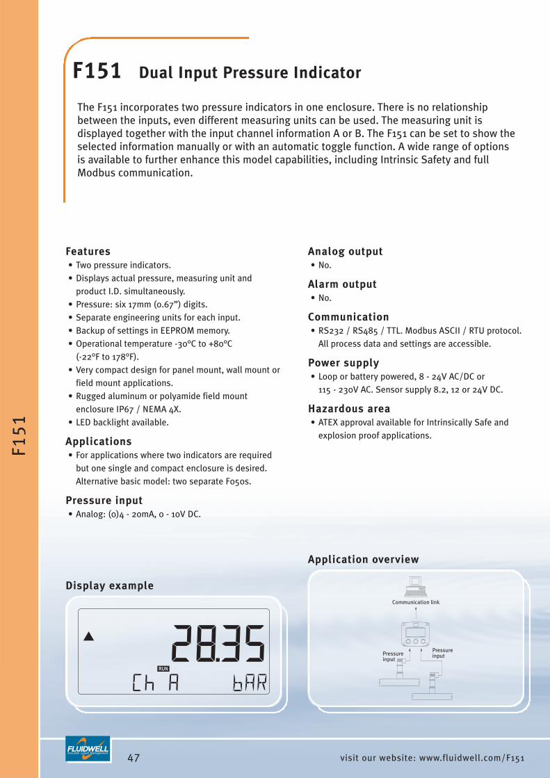
47 visit our website: www.fluidwell.com/F151
Communication link
PressureinputPressure
input
F15
1
F151 Dual Input Pressure Indicator
The F151 incorporates two pressure indicators in one enclosure. There is no relationshipbetween the inputs, even different measuring units can be used. The measuring unit isdisplayed together with the input channel information A or B. The F151 can be set to show theselected information manually or with an automatic toggle function. A wide range of optionsis available to further enhance this model capabilities, including Intrinsic Safety and fullModbus communication.
Features• Two pressure indicators.• Displays actual pressure, measuring unit and
product I.D. simultaneously.• Pressure: six 17mm (0.67”) digits.• Separate engineering units for each input.• Backup of settings in EEPROM memory.• Operational temperature -30°C to +80°C
(-22°F to 178°F).• Very compact design for panel mount, wall mount or
field mount applications.• Rugged aluminum or polyamide field mount
enclosure IP67 / NEMA 4X.• LED backlight available.
Applications• For applications where two indicators are required
but one single and compact enclosure is desired.Alternative basic model: two separate F050s.
Pressure input• Analog: (0)4 - 20mA, 0 - 10V DC.
Display example
Analog output• No.
Alarm output• No.
Communication• RS232 / RS485 / TTL. Modbus ASCII / RTU protocol.
All process data and settings are accessible.
Power supply• Loop or battery powered, 8 - 24V AC/DC or
115 - 230V AC. Sensor supply 8.2, 12 or 24V DC.
Hazardous area• ATEX approval available for Intrinsically Safe and
explosion proof applications.
Application overview

48visit our website: www.fluidwell.com/F153
Alarmoutput 4
Analogoutput
Communicationlink
Pressureinput
Alarmoutput 3
Alarmoutput 2
Alarmoutput 1
F15
3
F153 Pressure Monitor with analogand high / low alarm outputs
The F153 is a versatile pressure indicator with continuous pressure monitoring feature. It offers the ability to set two low pressure and two high pressure alarm values. If desired, analarm ignore function can be set up to allow for an incorrect pressure for a certain period oftime. Up to five outputs are available to transmit the alarm condition and actual pressure. The display shows the actual pressure, alarm values, alarm messages and status. On-screenengineering units are easily configured from a comprehensive selection. A wide range ofoptions further enhance this model capabilities, including Intrinsic Safety and full Modbuscommunication.
Features• Pressure monitoring: four alarm values can be set:
low-low, low, high and high-high pressure alarm.• Alarm values can be changed by the operator or
they can be password protected.• Analog output to transmit the actual pressure.• Up to four configurable alarm outputs.• Displays pressure, measuring unit and alarm
messages simultaneously.• Pressure and alarm values: six large 17mm
(0.67”) digits.• Alarm ignore function allows an incorrect pressure
for a certain period of time.• Selectable on-screen engineering units: mBar, Bar
and PSI.• LED backlight available.
Applications• Pressure measurement where continuous pressure
monitoring and re-transmitting is important, orserial communication is required. Alternative basicmodel: F050 or F053.
Pressure input• Analog: (0)4 - 20mA, 0 - 10V DC.
Display example
Analog output• One (0)4 - 20mA / 0 - 10V DC output to transmit the
pressure. The signal can be scaled to any range (e.g. from 100 PSI to +1100 PSI).
Alarm output• Up to four configurable alarm outputs for low-low,
low, high, high-high or any combination.
Communication• RS232 / RS485 / TTL. Modbus ASCII / RTU protocol.
All process data and settings are accessible.
Power supply• Loop or battery powered, 8 - 24V AC/DC or
115 - 230V AC. Sensor supply 8.2, 12 or 24V DC.
Hazardous area• ATEX approval available for Intrinsically Safe and
explosion proof applications.
Application overview

IntroductionThis product group offers a range of solutions from a basic level indicator up to apowerful level monitor with tank-shape linearization, high / low level monitoring, signal re-transmitting, four alarm outputs as well as full Modbus communication. All beingavailable for both safe area and hazardous area applications. Moreover, wireless data re-transmitting, remote level monitoring and vendor managed inventory - VMI - is offeredwith our M-series and ProcessMonitor.com products and services.
The functionality of these products is based on two main hardware platforms:• F0 platform: these products offer one signal input and can have one alarm or control
output. This is our basic product range.• F1 platform: these products have one or more signal inputs, multiple outputs and
communication option. This is our advanced product range.Both platforms share the same technology, enclosures, display and options but arededicated to their typical functionality.
Common Level Indicator features• Clear operator information is a key feature of these products. Essential information is
displayed as a clear text (e.g. “low level”) and not as mysterious abbreviations. • The dedicated display shows two lines of information at the same time, so the actual
level is displayed simultaneously with the height, percentage or alarm message.• The level is displayed with six 17mm (0.67”) high digits or even with 26mm (1”) high
digits (F070) with its engineering unit. Following units can be selected throughsoftware: ml, L, m3, GAL, USGAL, kg, lb, bbl or no unit.
• The height or percentage filled is displayed with 8mm (0.31”) digits. Followingengineering units can be selected: mm, cm, m, mtr, inch, ft, mmwk, mmwc, cmwk,cmwc, mwk, mwc, inwc, ftwc, mbar, bar, psi or no unit.
Further product specific features are found on the following pages.
49 visit our website: www.fluidwell.com/level
LEVEL INDICATORS, MONITORS AND TRANSMITTERS

Configuration menuAll configuration settings are accessed via a simpleoperator menu which can be password protected. Each setting is clearly indicated with an alphanumericdescription, therefore avoiding confusing abbreviationsand baffling codes. There are no sensitive DIP-switchesor trimmers, you simply select “Sensor” as mainfunction, after which you can select “span” or “offset”etc. Once familiar with one F-Series product, you willbe able to program all models in the series without amanual. All settings are safely stored in EEPROMmemory. The clear and easy structured configurationmenu is one of the most appreciated features of the F-Series.
Signal input typeFor the level indicators, two basic signal input typesare available:• Analog signal: (0)4 - 20mA or 4 - 20mA input loop
powered version. The input signal can be tunedwithin this range (e.g. from 4.0mA to 18.0mA). To avoid signal processing at minimum signal, a lowcut-off filter is available.
• Analog signal: 0 - 10V DC. The input signal can betuned within this range (e.g. from 2.0 to 5.0V DC). A low cut-off filter is available here too, to avoidcounting at minimum signal.
Further, a digital filter can be set to a desired value tostabilize the level measurement reading. The offsetfunction allows the sensor to be mounted above a notmeasured quantity (e.g. from 230 L). With the span,the indicator can be set to be operational within anydesired range (e.g. from 230 L to 10,000 L).
Data protectionAll settings are stored in EEPROM memory ensuringthat information is not lost in the event of powerfailure or battery exchange. The configuration menuand alarm values can be password protected toprevent unauthorized access.
For an explanation of all the F-Series options such asanalog and alarm outputs, communication, powersupply and enclosures, please read the section“Ordering codes” in the back of this catalog.
50visit our website: www.fluidwell.com/level
LEV
EL
IND
ICA
TOR
S
Product listingF070 Level Indicator.F073 Level Monitor with two high / low alarm values and one alarm output.F074 Level Controller with one control output.F077 Level Monitor with two high / low alarm values, eight point tank-shape linearization and one alarm output.F170 Level Monitor / Totalizer with four high / low alarm values, max. four alarm outputs, analog output and
communication option.F173 Level Monitor / Totalizer with four high / low alarm values, fifteen linearization points, max. four alarm
outputs, analog output and communication option.

51 visit our website: www.fluidwell.com/F070
Level input
F07
0
F070 Level Indicatorwith very large digits
The F070 is a straight forward level indicator with large 26mm (1”) high digits. It can be set todisplay the level as a quantity, height or as a percentage. The measuring unit to be displayedis simply selected through an alphanumeric configuration menu. No adhesive labels have tobe put on the outside of the enclosure: a weather proof and user-friendly solution! The configuration of the Span, off-set and number of decimals is done through softwarefunctions, without any sensitive DIP-switches or trimmers. A wide range of options furtherenhance this model capabilities, including Intrinsic Safety for hazardous area applications.
Features• Displays level and height or percentage filled.• Very large 26mm (1”) high digits for level.• Piegraph indication: ten segments.• Selectable on-screen engineering units for level:
ml, L, m3, GAL, USGAL, kg, lb, bbl or no unit.• Selectable on-screen units for height: mm, cm, m,
mtr, inch, ft, mmwk, mmwc, cmwk, cmwc, mwk,mwc, inwc, ftwc, mbar, bar, psi or no unit.
• Number of digits for level: 51/2.• Green/amber LED backlight with adjustable intensity.• Auto backup of settings in EEPROM memory.• Operational temperature -40°C to +80°C
(-40°F to 178°F).• Easy configuration with clear alphanumeric display.• Very compact design for panel mount, wall mount or
field mount applications.
Applications• Applications where a basic level measurement
display is required without level monitoring,linearization or signal re-transmitting. Moreadvanced models: F073, F077, F170 and F173.
Display example
Level input• Analog: (0)4 - 20mA, 0 - 10V DC.
Analog output• No.
Alarm output• No.
Communication• No.
Power supply• Loop or battery powered, 8 - 24V AC/DC or
115 - 230V AC. Sensor supply 8.2, 12 or 24V DC.
Hazardous area• ATEX, IECEx, CSA and FM approvals available for
Intrinsically Safe and non-incendive applications.• ATEX approval available for explosion proof
enclosure.
Application overview

52visit our website: www.fluidwell.com/F073
Level input
Alarm output
high
low
F07
3
F073 Level Monitor with one high / low alarm output
The F073 is a versatile level indicator with continuous level monitoring feature. It offers theability to set one low level and one high level alarm value. If desired, an alarm ignore functioncan be set up to allow for an incorrect level for a certain period of time. The configuration ofthe Span, off-set and number of decimals is done through software functions, without anysensitive DIP-switches or trimmers. The display shows the actual level, height or percentage,alarm values, alarm messages and status. On-screen engineering units are easily configuredfrom a comprehensive selection. A wide range of options further enhance this modelcapabilities, including Intrinsic Safety for hazardous area applications.
Features• Displays level and height or percentage filled
simultaneously.• Level monitoring: two alarm values can be set: low
and high level alarm.• Alarm values can be changed by the operator or
they can be password protected.• One alarm output for high, low or both level alarms.• Level: six large 17mm (0.67”) digits.• Selectable on-screen engineering units: ml, L, m3,
GAL, USGAL, kg, lb, bbl or no unit.• Selectable on-screen units for height: mm, cm, m,
mtr, inch, ft, mmwk, mmwc, cmwk, cmwc, mwk,mwc, inwc, ftwc, mbar, bar, psi or no unit.
• Red flashing LED backlight in case of a level alarm;intensity adjustable.
• Displays clear alarm messages.• Auto backup of settings in EEPROM memory.
Applications• Level measurement where continuous level
monitoring is important without signal re-transmitting. Alternative advanced models: F077and F173.
Display example
Level input• Analog: (0)4 - 20mA, 0 - 10V DC.
Analog output• No.
Alarm output• One configurable alarm output for high, low or both
level alarms.
Communication• No.
Power supply• Loop or battery powered, 8 - 24V AC/DC or
115 - 230V AC. Sensor supply 8.2, 12 or 24V DC.
Hazardous area• ATEX, IECEx, CSA and FM approvals available for
Intrinsically Safe and non-incendive applications.• ATEX approval available for explosion proof
enclosure.
Application overview

53 visit our website: www.fluidwell.com/F074
Level input
Control output
high
low
F07
4
F074 Level / Pump Controllerwith one control output
The F074 is a basic level / pump controller that works with a preset value and two switchpoints to control a pump or valve. The low and high level switch points are entered as apercentage of the preset value to switch the device on / off. For pump control applications,the function can be inverted to empty a well. A stable level within a band arround the presetvalue is the result. The display shows the actual level, preset value, high / low switch pointsand status. On-screen engineering units are easily configured from a comprehensiveselection. The configuration of the Span, off-set and number of decimals is done throughsoftware functions, without any sensitive DIP-switches or trimmers.
Features• Level control: high / low switch points and a preset
value can be set.• Displays actual level and preset value.• Switch points and preset value can be set by the
operator or being password protected.• One control output for on / off pump or valve
control.• Functions for filling-up a container or emptying a
well or tank.• Level: six large 17mm (0.67”) digits.• Selectable on-screen engineering units: ml, L, m3,
GAL, USGAL, kg, lb, bbl or no unit.• Green/amber LED backlight with adjustable intensity.• Auto backup of settings in EEPROM memory.• Operational temperature -40°C up to +80°C
(-40°F up to 178°F).• Very compact design for panel mount, wall mount or
field mount applications.
Applications• Basic on / off level control applications without
PI(D) control. Also very suitable for applicationswhere the required level changes frequently.
Display example
Level input• Analog: (0)4 - 20mA, 0 - 10V DC.
Analog output• No.
Control output• One on / off control output (e.g. for pump or valve
control) with the high / low level values.
Communication• No.
Power supply• Loop or battery powered, 8 - 24V AC/DC or
115 - 230V AC. Sensor supply 8.2, 12 or 24V DC.
Hazardous area• ATEX, IECEx, CSA and FM approvals available for
Intrinsically Safe and non-incendive applications.• ATEX approval available for explosion proof
enclosure.
Application overview

54visit our website: www.fluidwell.com/F077
Level input
Alarm output
high
lowLinearization
F07
7
F077 Level Monitor with linearization and one high / low alarm output
The F077 is a versatile level indicator with linearization and continuous level monitoringfeature. In addition to the average Span, eight linearization points can be entered tocompensate for the tank-shape. The unit will interpolate between these points to increase the accuracy. With the level monitoring feature, one low level and one high level alarm valuecan be set. The configuration of the Span, off-set and number of decimals is done through software functions, without any sensitive DIP-switches or trimmers. The display shows theactual level, height or percentage, alarm values, alarm messages and status. On-screenengineering units are easily configured from a comprehensive selection.
Features• Eight point linearization of the tank-shape - with
interpolation.• Level monitoring: two alarm values can be set: low
and high level alarm.• Displays level and height or percentage filled
simultaneously.• Alarm values can be changed by the operator or
they can be password protected.• Level: six large 17mm (0.67”) digits.• Selectable on-screen engineering units: ml, L, m3,
GAL, USGAL, kg, lb, bbl or no unit.• Selectable on-screen units for height: mm, cm, m,
mtr, inch, ft, mmwk, mmwc, cmwk, cmwc, mwk,mwc, inwc, ftwc, mbar, bar, psi or no unit.
• Red flashing LED backlight in case of a level alarm;intensity adjustable.
Applications• Level measurement where continuous level
monitoring and linearization of the tank-shape isimportant without signal re-transmitting. Alternativebasic models F070 and F073 or more advanced F170and F173.
Display example
Level input• Analog: (0)4 - 20mA, 0 - 10V DC.
Analog output• No.
Alarm output• One configurable alarm output for high, low or both
level alarms.
Communication• No.
Power supply• Loop or battery powered, 8 - 24V AC/DC or
115 - 230V AC. Sensor supply 8.2, 12 or 24V DC.
Hazardous area• ATEX, IECEx, CSA and FM approvals available for
Intrinsically Safe and non-incendive applications.• ATEX approval available for explosion proof
enclosure.
Application overview

55 visit our website: www.fluidwell.com/F170
alarmoutput R4
Analogoutput
Communicationlink
alarmoutput R3
alarmoutput R2
alarmoutput R1
high - high
high
low
low - low
F17
0
F170 Level Monitor with analog and high / low alarm outputs
The F170 is a versatile level indicator with continuous level monitoring feature. It offers theability to set two low level and two high level alarm values. If desired, an alarm ignorefunction can be set up to allow for an incorrect level for a certain period of time. Up to fiveoutputs are available to transmit the actual level and alarm condition. The display shows theactual level, height or percentage, alarm values, alarm messages and status. On-screenengineering units are easily configured from a comprehensive selection. A wide range ofoptions further enhance this model capabilities, including Intrinsic Safety and full Modbuscommunication.
Features• Level monitoring: four alarm values can be set:
low-low, low, high and high-high level alarm.• Alarm values can be changed by the operator or
they can be password protected.• Analog output to transmit the actual level.• Up to four configurable alarm outputs.• Level: six large 17mm (0.67”) digits.• Displays level, height or percentage and measuring
unit simultaneously.• Alarm ignore function allows an incorrect level for a
certain period of time.• Displays clear alarm messages.• LED backlight available.
Applications• Level measurement where continuous level
monitoring and re-transmitting is important or serialcommunication is required. Alternative basic model:F070, F073, F077 or more advanced model F173.
Level input• Analog: (0)4 - 20mA, 0 - 10V DC.
Display example
Analog output• One (0)4 - 20mA / 0 - 10V DC output to transmit the
level. The signal can be scaled to any range (e.g. from2.5m3 to 1400.0m3).
Alarm outputs• Up to four configurable alarm outputs for low-low,
low, high, high-high or any combination.
Communication• RS232 / RS485 / TTL. Modbus ASCII / RTU protocol.
All process data and settings are accessible.
Power supply• Loop or battery powered, 8 - 24V AC/DC or
115 - 230V AC. Sensor supply 8.2, 12 or 24V DC.
Hazardous area• ATEX approval available for Intrinsically Safe and
explosion proof applications.
Application overview

56visit our website: www.fluidwell.com/F173
alarmoutput R4
Analogoutput
Communicationlink
alarmoutput R3
alarmoutput R2
alarmoutput R1
high - highhigh
lowlow - low
Linearization
Level input
F17
3
F173 Level Monitor with linearization,analog and high / low alarm outputs
The F173 is a versatile level monitor with linearization and continuous level monitoringfeature. In addition to the average Span, fifteen linearization points can be entered tocompensate for the tank-shape. The unit will interpolate between these points to increase theaccuracy. With the level monitoring feature, one low level and one high level alarm value canbe set. It offers the ability to set two low level and two high level alarm values. If desired, analarm ignore function can be set up to allow for an incorrect level for a certain period of time.Up to five outputs are available to transmit the alarm condition and actual level. The displayshows the actual level, height or percentage, alarm values, alarm messages and status.
Features• Fifteen point linearization of the tank-shape - with
interpolation.• Level monitoring: four alarm values can be set:
low-low, low, high and high-high level alarm.• Alarm values can be changed by the operator or
they can be password protected.• Analog output to transmit the actual level.• Up to four configurable alarm outputs.• Level: six large 17mm (0.67”) digits.• Displays level, height or percentage and measuring
unit simultaneously.• Alarm ignore function allows an incorrect level for a
certain period of time.• Displays clear alarm messages.
Application• Level measurement where linearization of the
tank-shape and continuous level monitoring and re-transmitting is important or serial communicationis required. Alternative basic model: F070, F073,F077 and F170.
Level input• Analog: (0)4 - 20mA, 0 - 10V DC.
Display example
Analog output• One (0)4 - 20mA / 0 - 10V DC output to transmit the
level. The signal can be scaled to any range (e.g. from2.5m3 to 1400.0m3).
Alarm outputs• Up to four configurable alarm outputs for low-low,
low, high, high-high or any combination.
Communication• RS232 / RS485 / TTL. Modbus RTU protocol.
All process data and settings are accessible.
Power supply• Loop or battery powered, 8 - 24V AC/DC or
115 - 230V AC. Sensor supply 8.2, 12 or 24V DC.
Hazardous area• ATEX approval available for Intrinsically Safe and
explosion proof applications.
Application overview

Introduction This new product group offers several models which can be used for all kinds ofapplications. All models are available for both safe area and hazardous area applications.
The functionality of these products is based on two main hardware platforms:• F0 platform: these products offer one signal input and can have one alarm output.
This is our basic product range.• F1 platform: these products have one or more signal inputs, multiple outputs and
communication option. This is our advanced product range.Both platforms share the same technology, enclosures, display and options but arededicated to their typical functionality. A detailed description of each display and its typical features are found on the followingpages.
Configuration menuAll configuration settings are accessed via a simple operator menu which can bepassword protected. Each setting is clearly indicated with an alphanumeric description.There are no sensitive DIP-switches or trimmers, you simply select “sensor” as mainfunction, after which you can select “span” or “unit” etc. Once familiar with one F-Seriesproduct, you will be able to program all models in the series without a manual. All settings are safely stored in EEPROM memory in the event of sudden power failure.The clear and easy structured configuration menu is one of the most appreciated featuresof the F-Series.
Data protectionAll settings are stored in EEPROM memory ensuring that information is not lost in theevent of power failure or battery exchange.
For an explanation of all the F-Series options such as analog and control outputs,communication, power supply and enclosures, please read the section “Ordering codes”in the back of this catalog.
57 visit our website: www.fluidwell.com/generalpurpose
GENERAL PURPOSE DISPLAYS

58visit our website: www.fluidwell.com/generalpurpose
GE
NE
RA
LP
UR
PO
SE
DIS
PLA
YS
Product listingF090-A-PL General Purpose Indicator, loop powered with very large digits.F193 General Purpose Modbus display with analog and control outputs.F195 General Purpose Valve Position Indicator VPI, monitor and transmitter for hydraulic systems.F197 General Purpose Setpoint Generator with an analog (0)4 - 20mA or 0 - 10V DC output signal.

59 visit our website: www.fluidwell.com/F090
sensor4 - 20mA
inputF09
0
F090 General Purpose Indicator loop powered with very large digits
The F090-A-PL is an economical loop powered general purpose indicator with large 26mm (1”)high digits. The measuring unit to be displayed is simply selected through an alphanumericconfiguration menu. No adhesive labels have to be put on the outside of the enclosure: a weather proof and user-friendly solution! The configuration of the Span, off-set and numberof decimals is done through software functions, without any sensitive DIP-switches ortrimmers. A wide range of options further enhance this model capabilities, including IntrinsicSafety for hazardous area applications.
Features• Displays the actual value, measuring unit and loop
current.• Very large 26mm (1”) high digits.• Piegraph indication: ten segments.• Selectable on-screen engineering units: %, PPM,
meter, m, cm, mm, ft, sqft, ML, L, NL, M3, nM3, GAL,USGAL, IGAL, bbl, CUFT, mg, g, kg, ton, lb, psi, psig,mbar, bar, barg, °C, °F, K, P, RPM, K, KPA, /sec, /min,/hr, /day or no unit (others on request).
• Number of digits: 51/2.• Green/amber LED backlight with adjustable intensity.• Auto backup of settings in EEPROM memory.• Operational temperature -40°C to +80°C
(-40°F to 178°F).• Easy configuration with clear alphanumeric display.• Very compact design for panel mount, wall mount or
field mount applications.
Applications• Applications where a local general purpose display
is required without monitoring function or signal re-transmitting.
Display example
Signal input• Analog: 4 - 20mA input loop powered.
Analog output• No.
Alarm output• No.
Communication• No.
Power supply• Input loop powered through 4 - 20mA signal.
Hazardous area• ATEX, IECEx, CSA and FM approvals available for
Intrinsically Safe and non-incendive applications.• ATEX approval available for explosion proof
enclosure.
Application overview

60visit our website: www.fluidwell.com/F193
Alarmoutput 4
Analogoutput
Communication link
Alarmoutput 3
Alarmoutput 2
Alarmoutput 1
F19
3
F193 Modbus Display
The F193 is a versatile large digit Modbus display. All displayed information and signal outputsare controlled through the Modbus ASCII / RTU communication protocol. Information of ninedifferent tanks or products can be displayed. This information can be selected by the operator orwith an automatic toggle function. Off-course, the displayed information can also be selected andlocked through communication. Further, four control or alarm outputs can be controlled or beinglinked to an alarm status of the nine products: an alarm message will be displayed and the relatedrelay(s) switched. Also available is one analog output, controlled through the communication. The display shows the actual value, product / tank ID, measuring unit, alarm messages and status.
Features• Fully driven through Modbus communication link.• One up to and including nine different products or
tank values can be displayed• Displays actual value, product or tank I.D.,
measuring unit and alarm messages.• Actual values are operator selectable or being
displayed with the automatic toggle function butcan also be locked.
• Alarm values per product or tank can be assigned toan alarm output
• Alarms can be terminated through communicationor after operator interaction
• Up to four alarm outputs can be controlled throughcommunication or related to actual product values.
• One analog output value controlled throughcommunication.
• Actual value: six large 17mm (0.67”) digits.• LED backlight.
Applications• Local indication of process parameter(s) where the
actual information is provided through a Modbuscommunication link and not a sensor.
Display example
Signal input• No.
Analog output• One (0)4 - 20mA / 0 - 10V output to transmit any
value. The signal is scaled through communication.
Alarm output• Up to four configurable outputs controlled through
communication or as alarm output related to theactual product / tank values.
Communication• RS232 / RS485 / TTL. Modbus ASCII / RTU protocol.
All values and settings can be read and are setthrough this communication link, but can also bemanually changed through the display itself.
Power supply• Loop or battery powered, 8 - 24V AC/DC or
115 - 230V AC.
Hazardous area• ATEX approval available for Intrinsically Safe and
explosion proof applications.
Application overview

61 visit our website: www.fluidwell.com/F195
Pulse output Communication linkNegative flow output
90° or 270°out of phase
Analog output
F19
5
F195 Valve Position Indicator VPI for hydraulic systems
The F195 has been developed for the valve position indication and monitoring in hydraulicsystems. By using a bi-directional flowmeter to measure the volume displaced by theactuator, an accurate position of the system is calculated. The display does show the positionas a percentage as well as with the text “open” and “closed” for the minimum and maximumpositions. As standard, the analog output mirrors the percentage displayed which can be usedto transmit the valve position. The usual difficulties encountered in such applications include:very low flows, vibration, thermal expansion of the oil and high ambient temperatures. These are all well catered for in the design and operation of the F195.
Features• Valve position calculated through bi-directional flow
measurement.• Displays the position as 0 - 100%, the moved
volume and “open / closed” texts.• Analog output mirrors the position of the valve.• Modbus communication link for remote monitoring.• Re-calibration feature.• Service counter displays the number of full strokes.• Auto backup of settings in EEPROM memory.• Operational temperature -30°C to +80°C
(-22°F to 178°F).• Easy configuration with clear alphanumeric display.• Very compact design for panel mount, wall mount or
field mount applications.• LED backlight available.
Applications• Valve position indication and monitoring in hydraulic
systems. For example as valve position indicator VPIfor ballast tanks in ships.
Flowmeter input• Pulse: sine wave (coil), reed-switch, NPN, PNP,
Namur, active signal.
Display example
Pulse output• One scaled pulse output according to the
bi-directional accumulated total (e.g. one pulseevery 3.25 gallons). Max. frequency 64Hz. A secondoutput is switched as soon as the pulse outputreflects a “negative” quantity.
Analog output• One (0)4 - 20mA / 0 - 10V output to transmit the
position of the hydraulic systems (e.g. from 0% to 110%).
Communication• RS232 / RS485 / TTL. Modbus ASCII / RTU protocol.
All process data and settings are accessible.
Power supply• Loop or battery powered, 8 - 24V AC/DC or
115 - 230V AC. Sensor supply 3.2, 8.2, 12 or 24V DC.
Hazardous area• ATEX approval available for Intrinsically Safe and
explosion proof applications.
Application overview

62visit our website: www.fluidwell.com/F197
Communication link
manual(0)4 - 20mA / 0 - 10V DC
output
hot
cold
Alarm output 2 Alarm output 3
Temperatureinput F1
97
F197 Setpoint Generator
The F197 is a manual set-point generator. The operator enters an analog or a scaled outputvalue or a percentage which will be transmitted as a (0)4 - 20mA / 0 - 10V DC signal to a controldevice. If available, the F197 can also display the measured actual process value, however, thereis no direct control relationship between the input and output value. Further, one low and onehigh alarm value can be set with an alarm ignore function to monitor the process. The displayshows the preset value, actual value and status simultaneously. On-screen engineering unitsare easily configured from a comprehensive selection. A wide range of options furtherenhance this model capabilities, including Intrinsic Safety and full Modbus communication.
Features• Manual (0)4 - 20mA / 0 - 10V DC control output.• Preset value can be entered as a scaled value (e.g.
415°C), analog value (e.g. 15,3mA) or as percentage.• Displays the actual process value and transmitted
value simultanously.• One low and one high alarm value can be set with
alarm ignore time function.• Preset value: seven 17mm (0.67”) digits during
programming and 8mm (0.31”) digits duringprocess.
• Actual value: seven 17mm (0.67”) digits.• Modbus communication link for remote control.• LED backlight available.• Auto backup of settings in EEPROM memory.• Operational temperature -30°C to +80°C
(-22°F to 178°F).
Applications• Manual set-point control of process variables
requiring a (0)4 - 20mA or 0 - 10V input value. Forexample to tune temperature or flow rate manually.
Communication• RS232 / RS485 / TTL. Modbus RTU protocol.
All process data and settings are accessible.
Display example
Signal inputs (not required)• Pulse: sine wave (coil), reed-switch, NPN, PNP,
Namur, active pulse signal. • Analog: (0)4 - 20mA, 0 - 10V DC.Temperature input• PT100 - 2 or 3 wire.
Analog output• One (0)4 - 20mA / 0 - 10V output to transmit any
value. The signal is scaled manually by the operatoror through Modbus communication.
Alarm output• One low alarm and one high alarm output.
Power supply• Loop or battery powered, 8 - 24V AC/DC or
115 - 230V AC. Sensor supply 3.2, 8.2, 12 or 24V DC.
Hazardous area• ATEX approval available for Intrinsically Safe and
explosion proof applications.
Application overview

63 visit our website: www.fluidwell.com
ORDERING CODES
This section describes the options and ordering
codes of all F-Series products.
The symbol indicates if the function is available Intrinsically Safe. The table on thefollowing pages shows which options are available for each product. As it is our policy toimprove our products continuously, it is advised to check the datasheets on our websitewww.fluidwell.com for up-to-date information about the latest options available.
Sensor input signalThis is the primary signal input type of the device. The configuration menu of eachproduct allows you to select and adjust the signal parameters, without any sensitivemechanical DIP-switches, jumpers or trimmers. The analog input version “type A” is alsoavailable as 4 - 20mA input loop powered display (power supply type PL).A (0)4 - 20mA sensor input for flow, level, pressure and temperature measurement.
HThermocouple input for temperature measurement. Available types: check the latest datasheets.Pulse input for flow applications. Signal types: sine wave (coil), NPN, PNP, reed
P switch, Namur and active signals. For most signals a low pass filter can beenabled.
TPT100 (PRTD) input for temperature measurement, suitable for 2 or 3 wire (F0: 4 wire as well).
U 0 - 10V DC sensor input for flow, level, pressure and temperature measurement.X No primary signal input (model F193 only).
Analog output signalAvailable for the F1-Series only: related to the actual flow, level, height, pressure,temperature, percentage, ratio, consumption, differential or sum, position, energy or ascontrol output. Note: an active analog output comes with an active transistor output type OA and requires a power supply option type PD, PF or PM.AA Active 4 - 20mA analog output - requires OA + PD, PF or PM.AB Active 0 - 20mA analog output - requires OA + PD, PF or PM.
AFPassive floating 4 - 20mA analog output for Intrinsically Safe applications - requires PC, PD or PL.
AI Passive isolated 4 - 20mA analog output - requires PB, PD, PF, PL or PM.
APPassive 4 - 20mA analog output signal. Output loop powered which means thatthe unit will be powered through this loop (comes with type PX as standard).
AU Active analog output 0 - 10V DC - requires OA + PD, PF or PM.AX No analog output.
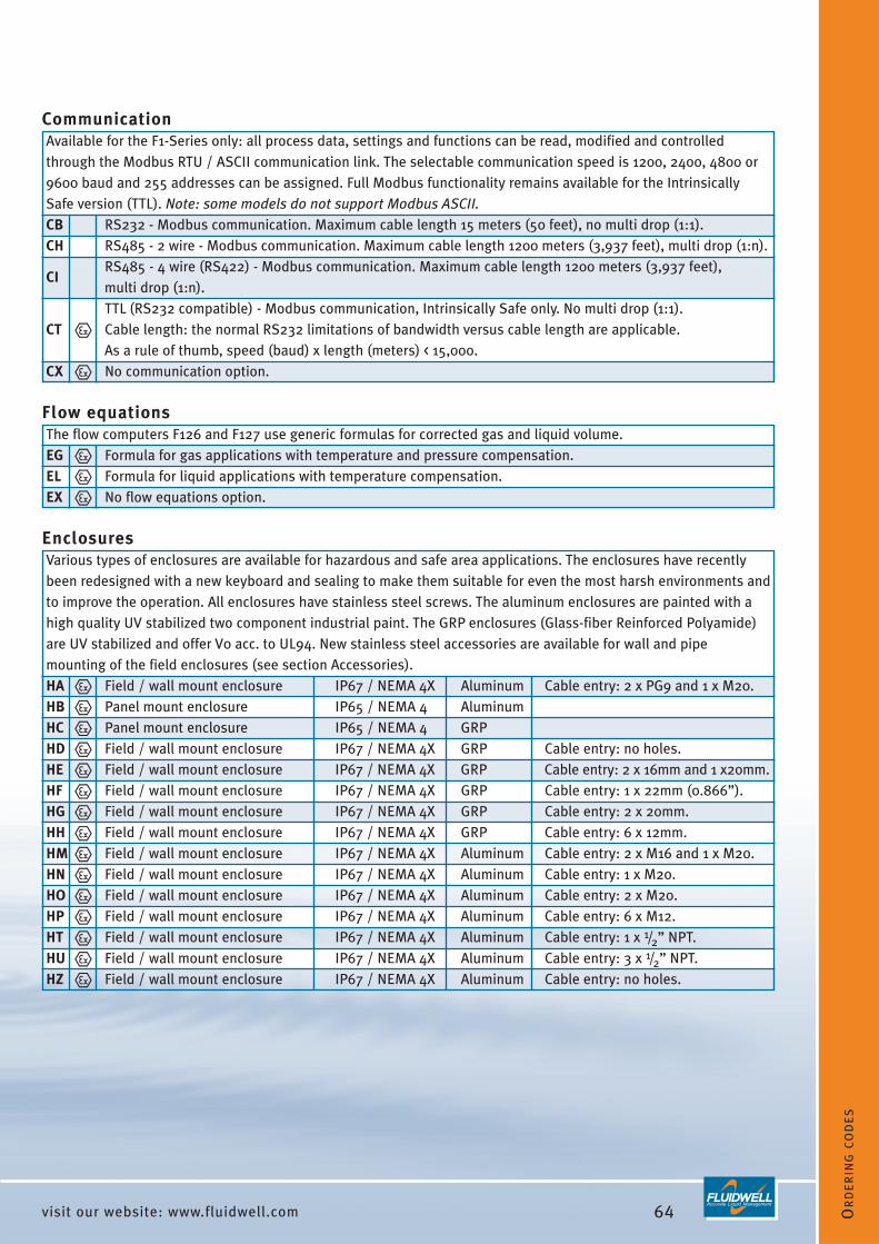
64visit our website: www.fluidwell.com OR
DE
RIN
GC
OD
ES
CommunicationAvailable for the F1-Series only: all process data, settings and functions can be read, modified and controlledthrough the Modbus RTU / ASCII communication link. The selectable communication speed is 1200, 2400, 4800 or9600 baud and 255 addresses can be assigned. Full Modbus functionality remains available for the IntrinsicallySafe version (TTL). Note: some models do not support Modbus ASCII.CB RS232 - Modbus communication. Maximum cable length 15 meters (50 feet), no multi drop (1:1).CH RS485 - 2 wire - Modbus communication. Maximum cable length 1200 meters (3,937 feet), multi drop (1:n).
CIRS485 - 4 wire (RS422) - Modbus communication. Maximum cable length 1200 meters (3,937 feet), multi drop (1:n).TTL (RS232 compatible) - Modbus communication, Intrinsically Safe only. No multi drop (1:1).
CT Cable length: the normal RS232 limitations of bandwidth versus cable length are applicable. As a rule of thumb, speed (baud) x length (meters) < 15,000.
CX No communication option.
Flow equationsThe flow computers F126 and F127 use generic formulas for corrected gas and liquid volume. EG Formula for gas applications with temperature and pressure compensation.EL Formula for liquid applications with temperature compensation.EX No flow equations option.
EnclosuresVarious types of enclosures are available for hazardous and safe area applications. The enclosures have recentlybeen redesigned with a new keyboard and sealing to make them suitable for even the most harsh environments andto improve the operation. All enclosures have stainless steel screws. The aluminum enclosures are painted with ahigh quality UV stabilized two component industrial paint. The GRP enclosures (Glass-fiber Reinforced Polyamide)are UV stabilized and offer V0 acc. to UL94. New stainless steel accessories are available for wall and pipemounting of the field enclosures (see section Accessories).HA Field / wall mount enclosure IP67 / NEMA 4X Aluminum Cable entry: 2 x PG9 and 1 x M20.HB Panel mount enclosure IP65 / NEMA 4 AluminumHC Panel mount enclosure IP65 / NEMA 4 GRPHD Field / wall mount enclosure IP67 / NEMA 4X GRP Cable entry: no holes.HE Field / wall mount enclosure IP67 / NEMA 4X GRP Cable entry: 2 x 16mm and 1 x20mm.HF Field / wall mount enclosure IP67 / NEMA 4X GRP Cable entry: 1 x 22mm (0.866”).HG Field / wall mount enclosure IP67 / NEMA 4X GRP Cable entry: 2 x 20mm.HH Field / wall mount enclosure IP67 / NEMA 4X GRP Cable entry: 6 x 12mm.HM Field / wall mount enclosure IP67 / NEMA 4X Aluminum Cable entry: 2 x M16 and 1 x M20. HN Field / wall mount enclosure IP67 / NEMA 4X Aluminum Cable entry: 1 x M20.HO Field / wall mount enclosure IP67 / NEMA 4X Aluminum Cable entry: 2 x M20.HP Field / wall mount enclosure IP67 / NEMA 4X Aluminum Cable entry: 6 x M12.HT Field / wall mount enclosure IP67 / NEMA 4X Aluminum Cable entry: 1 x 1/2” NPT.HU Field / wall mount enclosure IP67 / NEMA 4X Aluminum Cable entry: 3 x 1/2” NPT.HZ Field / wall mount enclosure IP67 / NEMA 4X Aluminum Cable entry: no holes.

65 visit our website: www.fluidwell.com
Inputs - additional pressure or switch inputAvailable for the F1-Series only: several products offer or require additional inputs withfollowing functionality:IA (0)4 - 20mA input for pressure measurement.IB Additional reset input to zero the totalizer.IU 0 - 10V DC input for pressure measurement.IX No additional input.
Outputs - alarm / pulse / controlFollowing switch output(s) are related to the totalizer (scaled pulse or alarm output),high / low alarms for flow, level, pressure or temperature or control outputs for the batchcontrollers. The F0-Series offers maximum one output. The F1-Series maximum of fouroutputs, however in case of an Intrinsically Safe application a maximum of two outputsare available. Except the passive transistor (type OT), all output types require a powersupply option type PD, PF or PM. For detailed information please consult the productdatasheet.
OAActive 24V transistor output(s), requires type PD, PF or PM. (F1-Series also: AA, AB or AU), max load: 50mA @ 24V DC.
ORMechanical SPST relays - isolated, requires type PF or PM, max. load 1A - 230V AC.
OS Four mechanical SPST relays - isolated, requires type PD, max. load 1A - 230V AC.
OTPassive transistor output(s), max. load 300mA @ 50V DC, (Intrinsically Safe max. 30V DC 100mA) per output.
OX No output.
Power supplyTo power the F-Series, several power supply options are available. For detailedinformation please consult the datasheet of the product.PB Long life lithium battery - only one battery required.PC Intrinsically Safe lithium battery - only one battery required. PD 16 - 24V DC power supply with limited sensor supply capabilities.PF 24V AC / DC power supply with full sensor supply.PL Input loop powered, the unit is powered through the 4 - 20mA signal input.PM 115 - 230V AC power supply with full sensor supply.
Sensor supply not available. PX F0-Series can be powered with 8 - 30V DC.
F1-Series can be powered by output loop (type AP), voltage: 8 - 30V DC.
Temperature - additional inputsAvailable for the F1-Series only: several products require additional inputs with followingfunctionality.TA (0)4 - 20mA input for temperature measurement.TP PT100 input for temperature measurement - 2 or 3 wire.TU 0 - 10V DC input for temperature measurement.TX No additional input.

66visit our website: www.fluidwell.com OR
DE
RIN
GC
OD
ES
Hazardous areaAll models can be supplied Intrinsically Safe with ATEX Certification. For the F0-Series IECEx, CSA and FM approvalas well as non-incendive approval are expected to become available during 2006. For detailed information andlatest information, please consult the datasheet and certificate of the product. XF ATEX - EExd flameproof enclosure II 2 GD EEx d IIB T5.XI ATEX - Intrinsically Safe: II 1 GD EEx ia IIB/IIC T4 T100°C.XN Non incendive: Expected fourth quarter 2006.XX Safe area application.
Other optionsSeveral other options are listed below. Please be aware that more than one of these options can be selected.
Bi-color backlight green/amber. In case of a monitoring application, the backlight can be set to switch to ZB red in case of an alarm condition.
Note: for the F1-Series, only a green backlight for safe area applications is available at this moment.ZF Extra high sensitivity for the sine wave (coil) input 10mV p-p.ZG Very high sensitivity for the sine wave (coil) input 5mV p-p.ZV PT100 (PRTD) range -200°C to +800°C (-328°F to +1472°F).ZX No additional option.

67 visit our website: www.fluidwell.com
ENCLOSURES
The following pages contain dimensional drawings
of the F-Series enclosures and mounting accessories.
75 mm (2.95")
129,6 mm (5.10")
112 mm (4.40")60
mm
(2.3
6")
120
mm
(4.7
2")
Field / wall mount enclosures, IP67 / NEMA4X
129,8 mm (5.11")
119,
4 m
m (4
.70"
)
31,4 mm(1.24")
29,1 mm(1.15")
Panel mount enclosures, IP65 / NEMA4

68visit our website: www.fluidwell.com
EN
CLO
SU
RE
S
115 mm (4.53")
98 m
m (3
.86"
)
Panel mount cut-out dimensions
Panel mountingA major advantage of using the F-Series as a panelmount unit is the minimum depth clearance required.This allows a small box being used compared to manyother panel mount devices.
Panel cut-out The panel cut-out can be rectangle where the fourbolts will be located in the corners.
Mounting the enclosure in a panelThe enclosure is supplied with four stainless steelbolts, O-rings, washers and nuts.
F-Series mounted in the cabinet After installing the unit, the thick silicon gasket doesassure a proper sealing.
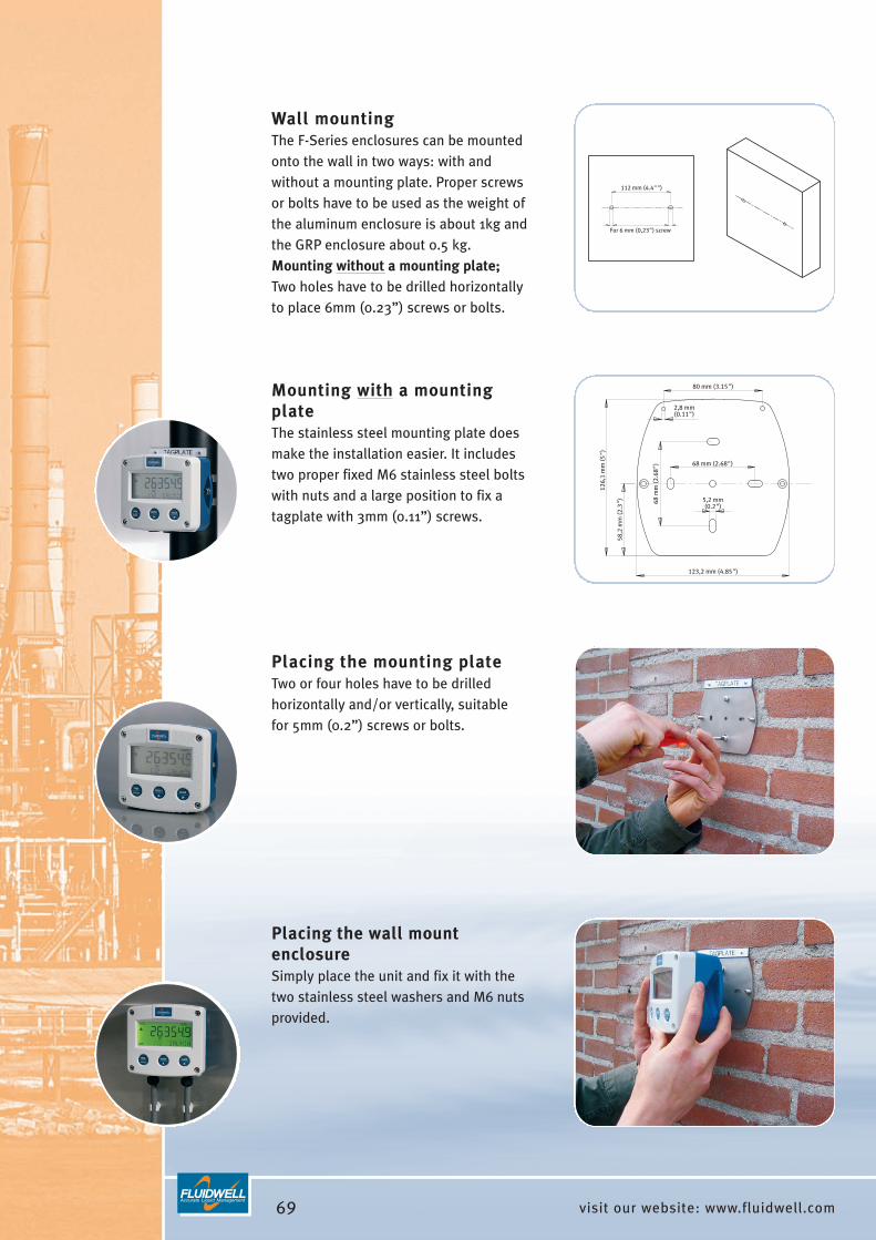
69 visit our website: www.fluidwell.com
2,8 mm(0.11")
80 mm (3.15")
5,2 mm(0.2")
126,
1 m
m (5
")
58,2
mm
(2.3
")
123,2 mm (4.85")
68 m
m (2
.68"
) 68 mm (2.68")
Mounting with a mountingplateThe stainless steel mounting plate doesmake the installation easier. It includestwo proper fixed M6 stainless steel boltswith nuts and a large position to fix atagplate with 3mm (0.11”) screws.
112 mm (4.4"")
For 6 mm (0,23") screw
Wall mountingThe F-Series enclosures can be mountedonto the wall in two ways: with andwithout a mounting plate. Proper screwsor bolts have to be used as the weight ofthe aluminum enclosure is about 1kg andthe GRP enclosure about 0.5 kg.Mounting without a mounting plate;Two holes have to be drilled horizontallyto place 6mm (0.23”) screws or bolts.
Placing the mounting plateTwo or four holes have to be drilledhorizontally and/or vertically, suitable for 5mm (0.2”) screws or bolts.
Placing the wall mountenclosureSimply place the unit and fix it with thetwo stainless steel washers and M6 nutsprovided.

70visit our website: www.fluidwell.com
EN
CLO
SU
RE
S
99,8 mm (3.93") 129,6 mm (5.10")
127,
9 m
m (5
.04"
)
84,1
mm
(3.3
1")
Minimum diameter:∅ 54,8 mm (2")
Pipe mountingThe F-Series enclosures can be mounted on anyhorizontal or vertical pipe from 54,8mm (2”) diameterwith the stainless steel pipe mounting kit. Properclamps have to used as the total weight including thealuminum enclosure is about 1,4 kg and including theGRP enclosure about 0,9 kg. On the top of themounting plate, a space is provided to place a propertagplate with 3mm (0.11”) screws.
Assembling the pipe mounting kitThe mounting kit includes three stainless steel M5bolts to fix the pipe mounting bracket horizontally orvertically on the mounting plate. When assembled, thepart can easily be fixed on the pipe with the stainlesssteel worm gear clamps.
Placing the field mount enclosureSimply place the unit and fix it with the two stainlesssteel washers and M6 nuts provided.

71 visit our website: www.fluidwell.com/accessories
ACCESSORIES
The following pages contain several accessories,
which are available for the F-Series.
Mounting accessoriesACF02 Stainless steel wall mouning kit includes screws and plugs.ACF05 Stainless steel pipe mounting kit (worm gear clamps not included).ACF06 Two stainless steel worm gear clamps Ø 44 - 56mm (1.73” - 2.20”). ACF07 Two stainless steel worm gear clamps Ø 58 - 75mm (2.29” - 2.95”). ACF08 Two stainless steel worm gear clamps Ø 77 - 95mm (3.04” - 3.74”). ACF09 Two stainless steel worm gear clamps Ø 106 - 138mm (4.18” - 5.43”).
ACF10Customized Grevopal tagplates for ACF02 and ACF05, including stainless steelscrews. Dimension: 95mm x 12.5mm (3.75” x 0.5”).
Stainless steel pipe mounting kit
Stainless steel wall mouning kit

72visit our website: www.fluidwell.com/accessories
AC
CE
SS
OR
IES
Cable glands
Cable gland accessoriesACF20 for HA enclosure: 2 x PG9, 1 x M20 includes O-rings - IP67 / NEMA 4X.ACF25 for HE enclosure: 2 x M16, 1 x M20 includes locknuts and O-rings - IP67 / NEMA 4X.ACF26 for HF enclosure: 1 x M20 includes locknut and O-ring - IP67 / NEMA 4X.ACF27 for HG enclosure: 2 x M20 includes locknuts and O-rings - IP67 / NEMA 4X.ACF28 for HH enclosure: 6 x M12 includes locknuts and O-rings - IP67 / NEMA 4X.ACF32 for HM enclosure: 2 x M16, 1 x M20 - includes O-rings - IP67 / NEMA 4X.ACF33 for HN enclosure: 1 x M20 - includes O-ring - IP67 / NEMA 4X.ACF34 for HO enclosure: 2 x M20 - includes O-rings - IP67 / NEMA 4X.ACF35 for HP enclosure: 6 x M12 - includes O-rings - IP67 / NEMA 4X.ACF39 for HT enclosure: 1 x 1/2”NPT - includes O-ring - IP67 / NEMA 4X.ACF40 for HU enclosure: 3 x 1/2”NPT - includes O-rings - IP67 / NEMA 4X.
Blind plugs
Blind plug accessoriesACF50 for HA enclosure: 2 x PG9, 1 x M20 includes O-rings - IP67 / NEMA 4X.ACF55 for HE enclosure: 2 x M16, 1 x M20 includes locknuts and O-rings - IP67 / NEMA 4X.ACF56 for HF enclosure: 1 x M20 includes locknut and O-ring - IP67 / NEMA 4X.ACF57 for HG enclosure: 2 x M20 includes locknuts and O-rings - IP67 / NEMA 4X.ACF58 for HH enclosure: 6 x M12 includes locknuts and O-rings - IP67 / NEMA 4X.ACF62 for HM enclosure: 2 x M16, 1 x M20 - includes O-rings - IP67 / NEMA 4X.ACF63 for HN enclosure: 1 x M20 - includes O-ring - IP67 / NEMA 4X.ACF64 for HO enclosure: 2 x M20 - includes O-rings - IP67 / NEMA 4X.ACF65 for HP enclosure: 6 x M12 - includes O-rings - IP67 / NEMA 4X.ACF69 for HT enclosure: 1 x 1/2”NPT - includes O-rings - IP67 / NEMA 4X.ACF70 for HU enclosure: 3 x 1/2”NPT - includes O-rings - IP67 / NEMA 4X.

73 visit our website: www.fluidwell.com/accessories
Intrinsically Safe isolators accessories
Ordering code DescriptionHazardous Safe
area areaOne channel pulse or switch output type OT: 1 mechanic
ACG01 MTL5011B transfer from hazardous area to safe area, passive make-and-including power supply. transistor break relayOne channel power supply from safe area
ACG02 MTL5025to hazardous area (e.g. to power the unit device to
20 - 35V DCwith type PD or to power a switching be poweredor analog device in hazardous area).
type AP / AF:
ACG03 MTL5042One channel 4 - 20mA repeater from
passive floatinghazardous area to safe area, including
analog 4 - 20mApower supply.
output
Bi-direction serial-data isolator type CT:RS232,
ACG04 MTL5051(for Modbus communication). TTL
RS422or TTL
Two channel pulse or switch output type OT:
2 mechanicACG05 MTL5018 transfer from hazardous area to safe area,
transistormake-and-
including power supply. break relaysOne channel pulse or switch output type OT: floating
ACG06 MTL5012 transfer from hazardous area to safe passive solidarea, including power supply. transistor stateOne channel isolated driver bringing
activeACG07 MTL5045 4 - 20mA from safe area to hazardous
4 - 20mA4 - 20mA
area, including power supply.
MTL isolators

74visit our website: www.fluidwell.com 75
Ordering overview
A H P T U X AA AB AF AI AP AU AX CB CH CI CT CX EG EL EX IA IB IU IX OA OR OS OT OX PB PC PD PF PL PM PX TA TP TU TX XF XI XN XX ZB ZF ZG ZV ZX
F010 ● ● ● ● ● ● ● ● ● ● ● ● ● ● ● ● ● ● ● ● ● ● ● ● ●
F011 ● ● ● ● ● ● ● ● ● ● ● ● ● ● ● ● ● ● ● ● ● ● ● ● ●
F012 ● ● ● ● ● ● ● ● ● ● ● ● ● ● ● ● ● ● ● ● ● ● ● ● ●
F013 ● ● ● ● ● ● ● ● ● ● ● ● ● ● ● ● ● ● ● ● ● ● ● ● ● ● ●
F014 ● ● ● ● ● ● ● ● ● ● ● ● ● ● ● ● ● ● ● ● ● ● ● ● ● ● ●
F016 ● ● ● ● ● ● ● ● ● ● ● ● ● ● ● ● ● ● ● ● ● ● ● ● ● ● ●
F110 ● ● ● ● ● ● ● ● ● ● ● ● ● ● ● ● ● ● ● ● ● ● ● ● ● ● ● ● ● ● ● ● ● ● ●
F111 ● ● ● ● ● ● ● ● ● ● ● ● ● ● ● ● ● ● ● ● ● ● ● ● ● ● ● ● ●
F112 ● ● ● ● ● ● ● ● ● ● ● ● ● ● ● ● ● ● ● ● ● ● ● ● ● ● ● ● ● ● ● ● ● ● ●
F113 ● ● ● ● ● ● ● ● ● ● ● ● ● ● ● ● ● ● ● ● ● ● ● ● ● ● ● ● ● ● ● ● ● ● ● ●
F115 ● ● ● ● ● ● ● ● ● ● ● ● ● ● ● ● ● ● ● ● ● ● ● ● ● ● ● ● ● ● ●
F117 ● ● ● ● ● ● ● ● ● ● ● ● ● ● ● ● ● ● ● ● ● ● ● ● ● ● ● ● ● ● ●
F118 ● ● ● ● ● ● ● ● ● ● ● ● ● ● ● ● ● ● ● ● ● ● ● ● ● ● ● ● ● ● ● ● ● ●
F114 ● ● ● ● ● ● ● ● ● ● ● ● ● ● ● ● ● ● ● ● ● ● ● ● ● ● ● ● ● ● ● ● ● ●
F116 ● ● ● ● ● ● ● ● ● ● ● ● ● ● ● ● ● ● ● ● ● ● ● ● ● ● ● ● ● ● ● ● ● ●
F126-el ● ● ● ● ● ● ● ● ● ● ● ● ● ● ● ● ● ● ● ● ● ● ● ● ● ● ● ● ● ● ● ● ● ● ●
F126-eg ● ● ● ● ● ● ● ● ● ● ● ● ● ● ● ● ● ● ● ● ● ● ● ● ● ● ● ● ● ● ● ● ● ● ● ●
F127-el ● ● ● ● ● ● ● ● ● ● ● ● ● ● ● ● ● ● ● ● ● ● ● ● ● ● ● ● ● ● ● ● ● ● ●
F128 ● ● ● ● ● ● ● ● ● ● ● ● ● ● ● ● ● ● ● ● ● ● ● ● ● ● ● ● ● ● ● ● ● ● ● ● ●
F030 ● ● ● ● ● ● ● ● ● ● ● ● ● ● ● ● ● ● ● ● ● ● ● ● ● ● ●
F130 ● ● ● ● ● ● ● ● ● ● ● ● ● ● ● ● ● ● ● ● ● ● ● ● ● ● ● ● ●
F131 ● ● ● ● ● ● ● ● ● ● ● ● ● ● ● ● ● ● ● ● ● ● ● ● ● ● ● ● ● ● ● ● ● ●
F133 ● ● ● ● ● ● ● ● ● ● ● ● ● ● ● ● ● ● ● ● ● ● ● ● ● ●
F134 ● ● ● ● ● ● ● ● ● ● ● ● ● ● ● ● ● ● ● ● ● ● ● ● ● ● ● ● ● ● ● ● ● ●
F136 ● ● ● ● ● ● ● ● ● ● ● ● ● ● ● ● ● ● ● ● ● ● ● ● ● ● ● ● ● ● ● ● ● ●
F040 ● ● ● ● ● ● ● ● ● ● ● ● ● ● ● ● ● ● ● ● ● ● ● ● ●
F043 ● ● ● ● ● ● ● ● ● ● ● ● ● ● ● ● ● ● ● ● ● ● ● ● ● ● ●
F141 ● ● ● ● ● ● ● ● ● ● ● ● ● ● ● ● ● ● ● ● ● ● ● ● ● ● ●
F143 ● ● ● ● ● ● ● ● ● ● ● ● ● ● ● ● ● ● ● ● ● ● ● ● ● ● ● ● ● ● ● ● ● ● ●
F050 ● ● ● ● ● ● ● ● ● ● ● ● ● ● ● ● ● ● ● ● ● ●
F053 ● ● ● ● ● ● ● ● ● ● ● ● ● ● ● ● ● ● ● ● ● ● ● ●
F151 ● ● ● ● ● ● ● ● ● ● ● ● ● ● ● ● ● ● ● ● ● ● ● ● ●
F153 ● ● ● ● ● ● ● ● ● ● ● ● ● ● ● ● ● ● ● ● ● ● ● ● ● ● ● ● ● ● ● ● ●
F070 ● ● ● ● ● ● ● ● ● ● ● ● ● ● ● ● ● ● ● ● ● ●
F073 ● ● ● ● ● ● ● ● ● ● ● ● ● ● ● ● ● ● ● ● ● ● ● ●
F074 ● ● ● ● ● ● ● ● ● ● ● ● ● ● ● ● ● ● ● ● ● ● ● ●
F077 ● ● ● ● ● ● ● ● ● ● ● ● ● ● ● ● ● ● ● ● ● ● ● ●
F170 ● ● ● ● ● ● ● ● ● ● ● ● ● ● ● ● ● ● ● ● ● ● ● ● ● ● ● ● ● ● ● ● ●
F173 ● ● ● ● ● ● ● ● ● ● ● ● ● ● ● ● ● ● ● ● ● ● ● ● ● ● ● ● ● ● ● ● ●
F090 ● ● ● ● ● ● ● ● ● ● ● ● ●
F193 ● ● ● ● ● ● ● ● ● ● ● ● ● ● ● ● ● ● ● ● ● ● ● ● ● ● ● ● ● ●
F195 ● ● ● ● ● ● ● ● ● ● ● ● ● ● ● ● ● ● ● ● ● ● ● ● ● ● ● ● ● ● ●
F197 ● ● ● ● ● ● ● ● ● ● ● ● ● ● ● ● ● ● ● ● ● ● ● ● ● ● ● ● ● ● ● ● ● ● ● ●
Leve
lIn
dica
tors
Gen
eral
P
urp.
Dis
play
Pres
sure
Indi
cato
rsTe
mpe
ratu
reIn
dica
tors
Bat
ch C
ontr
olle
rsFl
ow C
ompu
ters
Flow
rat
e In
dica
tors
/ T
otal
izer
s
Sensor input signal Analog output signal CommunicationFlow
equationsEnclosures
Additional inputs
Switch outputs Power supplyTemperatureinput signal
Hazardous area Other options
from HA to HZ
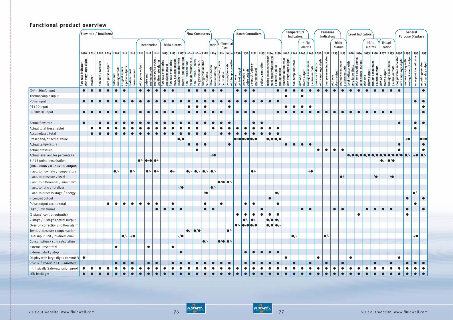
76visit our website: www.fluidwell.com 77
flow
rat
e in
dica
tor
wit
hve
ry la
rge
digi
ts
tota
lize
r
flow
rat
e /
tota
lize
r
wit
h pu
lse
outp
ut
puls
e an
d an
alog
out
puts
2 si
gnal
inpu
ts2
puls
e ou
tput
sbi
-dir
ecti
onal
m
easu
rem
ent
wit
h pu
lse
outp
ut
puls
e an
d an
alog
out
puts
anal
og +
pul
se o
utpu
ttw
o fl
ow r
ate
alar
ms
flow
rat
e m
onit
orin
gon
e al
arm
out
put
flow
rat
e m
onit
orin
gm
ax. 4
ala
rm o
utpu
tsto
tali
zer
mon
itor
wit
hal
arm
+ a
nalo
g ou
tput
flow
+ t
empe
ratu
re
for
liqu
id v
olum
e ca
lc.
flow
+ t
emp.
+ p
ress
.fo
r ga
s vo
lum
e ca
lc.
ener
gy c
onsu
mpt
ion
calc
ulat
ion
rati
o ca
lcul
atio
nan
d m
onit
orin
gco
nsum
ptio
n /
sum
calc
ulat
ion
cons
umpt
ion
calc
.w
ith
tem
p. c
orre
ctio
nw
ith
one
cont
rol o
utpu
ttw
o co
ntro
l or
puls
e ou
tput
s2
cont
rol/
puls
e +
anal
og o
utpu
t
deli
very
con
trol
ler
anal
og o
utpu
t for
sm
ooth
mul
ti-s
tage
val
ve c
ontr
ol2
cont
rol /
pul
se +
an
alog
out
put
tem
pera
ture
indi
cato
rw
ith
very
larg
e di
gits
dual
tem
p. in
dica
tor
wit
h on
e al
arm
out
put
anal
og +
max
imum
4 al
arm
out
puts
pres
sure
indi
cato
r w
ith
very
larg
e di
gits
dual
pre
ssur
e in
dica
tor
wit
h on
e al
arm
out
put
anal
og +
max
imum
4 al
arm
out
puts
leve
l ind
icat
or w
ith
very
larg
e di
gits
wit
h on
e on
/off
pum
p/va
lve
cont
rol o
utpu
tw
ith
one
alar
m o
utpu
tan
alog
+ m
axim
um4
alar
m o
utpu
tsw
ith
one
alar
m o
utpu
tan
alog
+ m
axim
um4
alar
m o
utpu
tslo
op p
ower
ed in
dica
tor
wit
h ve
ry la
rge
digi
tsm
odbu
s di
spla
y w
ith
anal
og +
con
trol
out
put
valv
e po
siti
on in
dica
tor
setp
oint
gen
erat
or
wit
h an
alog
out
put
F010 F011 F012 F014 F110 F111 F115 F016 F112 F118 F013 F113 F117 F126-EL F126-EG F128 F114 F116 F127-EL F030 F130 F131 F133 F134 F136 F040 F141 F043 F143 F050 F151 F053 F153 F070 F074 F073 F170 F077 F173 F090 F193 F195 F197
(0)4 - 20mA input ● ● ● ● ● ● ● ● ● ● ● ● ● ● ● ● ● ● ● ● ● ● ● ● ● ● ● ● ● ● ● ● ● ● ● ●
Thermocouple input ● ●
Pulse input ● ● ● ● ● ● ● ● ● ● ● ● ● ● ● ● ● ● ● ● ● ● ● ● ● ● ●
PT100 input ● ● ● ● ● ● ● ● ●
0 - 10V DC input ● ● ● ● ● ● ● ● ● ● ● ● ● ● ● ● ● ● ● ● ● ● ● ● ● ● ● ● ● ● ● ● ● ● ●
Actual flow rate ● ● ● ● ● ● ● ● ● ● ● ● ● ● ● ● ● ● ● ● ● ● ●
Actual total (resettable) ● ● ● ● ● ● ● ● ● ● ● ● ● ● ● ● ● ● ● ● ● ● ● ●
Accumulated total ● ● ● ● ● ● ● ● ● ● ● ● ● ● ● ● ● ● ● ● ● ● ●
Preset and/or actual value ●/● ●/● ●/● ●/● ●/● ●/● -/● ●/●
Actual temperature ● ● ● ● ● ● ● ● ● ●
Actual pressure ● ● ● ● ● ● ●
Actual level and/or percentage -/● ●/● ●/● ●/● ●/● ●/● ●/● ●/● ●/- -/● ●/-
8 / 15 point linearization ●/- ●/● ●/- ●/- ●/●
(0)4 - 20mA / 0 - 10V DC output:
- acc. to flow rate / temperature ●/- ●/- ●/- ●/- ●/- ●/- ●/- ●/- ●/- ●/- -/●
- acc. to pressure / level ●/- -/● -/●
- acc. to differential / sum flowr. ●/● ●/-
- acc. to ratio / totalizer -/● ●/-
- acc. to process stage / energy -/● ●/- ●/-
- control output ● ● ●
Pulse output acc. to total ● ● ● ● ● ● ● ● ● ● ● ● ● ●
High / low alarms ● ● ● ● ● ● ● ● ● ● ● ● ● ● ● ● ●
(1 stage) control output(s) ● ● ● ● ● ● ● ●
2 stage / 8 stage control output ●/- ●/- ●/● ●/-
Overrun correction / no flow alarm ●/- ●/● ●/● ●/● ●/-
Temp. / pressure compensation ●/- ●/● ●/-
Dual input unit / bi-directional ●/- -/● -/● ●/- ●/- -/●
Consumption / sum calculation ●/- ●/● ●/-
External reset total ● ● ●
External start / stop ● ● ● ● ● ●
Display with large digits 26mm(1”) ● ● ● ● ●
RS232 / RS485 / TTL - Modbus ● ● ● ● ● ● ● ● ● ● ● ● ● ● ● ● ● ● ● ● ● ● ● ● ● ● ●
Intrinsically Safe/explosion proof ● ● ● ● ● ● ● ● ● ● ● ● ● ● ● ● ● ● ● ● ● ● ● ● ● ● ● ● ● ● ● ● ● ● ● ● ● ● ● ● ● ● ●
LED backlight ● ● ● ● ● ● ● ● ● ● ● ● ● ● ● ● ● ● ● ● ● ● ● ● ● ● ● ● ● ● ● ● ● ● ● ● ● ● ● ● ● ● ●
Functional product overviewFlow rate / Totalizers Flow Computers Temperature
IndicatorsPressure
IndicatorsLevel Indicators
General Purpose Displays
Batch Controllers
linearization hi/lo alarmshi/lo
alarmshi/lo
alarmshi/lo
alarmslineari-zation
ratio differential/ sum
visit our website: www.fluidwell.com