Processor Pipelining
38
14:332:331 The Processor (datapath and pipelining) Address Instruction Instruction Memory Write Data Reg Addr Reg Addr Reg Addr Register File ALU Data Memory Address Write Data Read Data PC Read Data Read Data
-
Upload
paranoid486 -
Category
Documents
-
view
229 -
download
0
Transcript of Processor Pipelining

8/12/2019 Processor Pipelining
http://slidepdf.com/reader/full/processor-pipelining 1/144
14:332:331
The Processor(datapath and pipelining)
Address Instruction
Instruction
Memory
Write Data
Reg Addr
Reg Addr
Reg Addr
Register
File ALUData
Memory
Address
Write Data
Read DataPC
Read
Data
Read
Data

8/12/2019 Processor Pipelining
http://slidepdf.com/reader/full/processor-pipelining 2/144
Review: Design Principles Simplicity favors regularity
fixed size instructions and data – 32-bits Good design demands good compromises-
Only three instruction formats
Smaller is faster-
limited instruction set
limited number of registers in register file
limited number of addressing modes
Make the common case fast-arithmetic operands from the register file (load-store
machine)
allow instructions to contain immediate operands

8/12/2019 Processor Pipelining
http://slidepdf.com/reader/full/processor-pipelining 3/144
We're ready to look at an implementation of the MIPS
Simplified to contain only:
memory-reference instructions: lw, sw
arithmetic-logical instructions: add, sub, and,
or, slt
control flow instructions: beq, j
The Processor: Datapath & Control

8/12/2019 Processor Pipelining
http://slidepdf.com/reader/full/processor-pipelining 4/144
Generic implementation (first two stages are same):
use the program counter (PC) to supplythe instruction address and fetch theinstruction from memory (and update the PC)
decode the instruction (and read registers)
execute the instruction
All instructions (except j) use the ALU after reading the
registers
The Processor: Datapath & ControlFetch
PC = PC+4
DecodeExec

8/12/2019 Processor Pipelining
http://slidepdf.com/reader/full/processor-pipelining 5/144
Abstract Implementation View Two types of functional units:
elements that operate on data (combinational – likeALU) elements that contain state (sequential - registers and
memory)

8/12/2019 Processor Pipelining
http://slidepdf.com/reader/full/processor-pipelining 6/144
Abstract Implementation View
Control
Unit
DataMemory
Address
Write Data
Read Dataoverflow
Write Data
Read Addr 1
Read Addr 2
Write Addr
Register
File
Read
Data 1
Read
Data 2
ALU
z
ero
Address Instruction
Instruction
Memory
PC
Single cycle operation (multi-cycle presented later)
Split memory (Harvard ) model - one memory forinstructions (instruction cache) and one for data
Shows how PC is incremented or changed by branchtaken, does not show multiplexors or control lines

8/12/2019 Processor Pipelining
http://slidepdf.com/reader/full/processor-pipelining 7/144
Clocking Methodologies Clocking methodology defines when signals can be read
and when they can be written. Do not read while writing- unpredictable result falling (negative) edge
rising (positive) edgecycle time
We adopt an edge-triggered clocking methodology =update on clock edge
Values stored in the state elements are updated only on a
clock edge. Input to combinatorial element are values stored by the state elements in a previous clock cycle,
Combinatorial elements output can be used in the following clock cycle.
8/12/2019 Processor Pipelining
http://slidepdf.com/reader/full/processor-pipelining 8/144
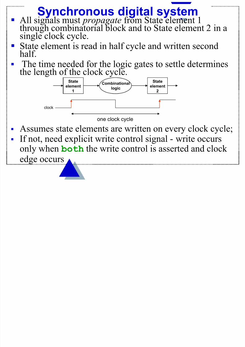
Synchronous digital system All signals must propagate from State element 1
through combinatorial block and to State element 2 in asingle clock cycle.
State element is read in half cycle and written secondhalf.
The time needed for the logic gates to settle determinesthe length of the clock cycle.
State
element1
State
element2
Combinationallogic
clock
one clock cycle
Assumes state elements are written on every clock cycle; If not, need explicit write control signal - write occurs
only when both the write control is asserted and clockedge occurs

8/12/2019 Processor Pipelining
http://slidepdf.com/reader/full/processor-pipelining 9/144
Building the Datapath The datapath assures that data travels between
various memory units to registers and ALUs;
The control unit regulates this transfer anddetermines what actions are to be taken on the data.
It does so using control lines that are connected to
various hardware units.
The edge triggered clock methodology allows a givenstate element to be both read and be written to in asingle clock cycle.
Either we have a long clock cycle for one instruction(length is determined by the slowest instruction), ormultiple cycles per instruction.

8/12/2019 Processor Pipelining
http://slidepdf.com/reader/full/processor-pipelining 10/144
Building the Datapath
What are the “building blocks” needed to implement a
subset of the MIPS instructions (lw, sw, arithmetic andlogic instructions - like add , sub, and , or, slt)? Any instruction needs to be fetched and the PC
incremented by 4
Read
AddressInstruction
InstructionMemory
Add
PC
4
Special ALU that only adds
PC is updated on
every clock cycle
Instruction Memory is
read every cycle, so it
doesn’t need an explicitread control signal
Extend later for j, beq

8/12/2019 Processor Pipelining
http://slidepdf.com/reader/full/processor-pipelining 11/144
Decoding Instructions Decoding instructions involves
sending the fetched instruction’s opcode andfunction field bits to the control unit
Instruction
Write Data
Read Addr 1
Read Addr 2
Write Addr
Register
File
Read
Data 1
Read
Data 2
Control
Unit
reading two values from the Register FileRegister File addresses are contained in the
instruction
5
532
32

8/12/2019 Processor Pipelining
http://slidepdf.com/reader/full/processor-pipelining 12/144
overflowInstruction
Write Data
Read Addr 1
Read Addr 2
Write Addr
Register
File
Read
Data 1
Read
Data 2
ALU zero
R format operations (add , sub, slt, and , or)
Executing R Format Operations
R-type:31 25 20 15 5 0
op rs rt rd functshamt
10
ALU control
4
32
32
– perform the indicated (by op and funct) operation onvalues in rs and rt
– store the result back into the Register File (intolocation rd )
The fourth ALU control line supports NOR

8/12/2019 Processor Pipelining
http://slidepdf.com/reader/full/processor-pipelining 13/144
Note that Register File is not written every cycle (e.g.
sw), so we need an explicit write control signal forthe Register File (RegWrite)
Executing R Format Operations
RegWrite
32
Instruction
Write Data
Read Addr 1
Read Addr 2
Write Addr
Register
File
Read
Data 1
Read
Data 2
ALU
overflow
zero
ALU control
4
32
32
To execute lw or sw operations we need a Data
Memory unit with two control signals for write into( MemWrite) and read from ( MemRead )
MemWrite
MemRead
Data
Memory
Address
Write Data
Read Data

8/12/2019 Processor Pipelining
http://slidepdf.com/reader/full/processor-pipelining 14/144
Executing Load and Store Operations
Load and store operations compute a memory address by adding the base register (in rs) to the 16-bit signed
offset field in the instruction
The 32 bits in the base register were read from the
Register File during decode
The offset value in the low order 16 bits of theinstruction must be sign extended to create a 32-bit
signed value
I-Type: op rs rt address offset
31 25 20 15 0

8/12/2019 Processor Pipelining
http://slidepdf.com/reader/full/processor-pipelining 15/144
Data
Memory
Address
Write Data
Read Data
MemWrite
MemRead
16 32
Sign
Extend
16-bit offset
RegWrite
Read Addr 1 zero
ALU
overflow
Write Data
InstructionRead Addr 2
Write Addr
Register
File
Read
Data 1
Read
Data 2
ALU control
sw - value read from the Register File during decode must be written to the Data Memory
lw - value read from the Data Memory must be stored in the
Register File
Executing Load and Store Operations

8/12/2019 Processor Pipelining
http://slidepdf.com/reader/full/processor-pipelining 16/144
Executing Branch Operations
Branch operations have to compare the operands readfrom the Register File during decode (rs and rt
values) for equality (zero ALU output is asserted) compute the branch target address by adding the
updated PC to the sign extended 16-bit signed offset
field in the instruction
offset value in the low order 16 bits of the instruction
must be sign extended to create a 32-bit signed value
and then shifted left 2 bits to turn it into a word address
I-Type: op rs rt address offset
31 25 20 15 0

8/12/2019 Processor Pipelining
http://slidepdf.com/reader/full/processor-pipelining 17/144
Executing Branch Operations
RegWrite
Read Addr 1 zero
ALU
overflow
Write Data
InstructionRead Addr 2
Write Addr
Register
File
Read
Data 1
Read
Data 2
ALU control
(to branch control logic -take
branch if zero line is high)
Add
Branch
target
addressShift
left 2
Add
4
PC
PC + 4
(perform a subtraction)
3216
16-bit offset
Sign
Extend
8/12/2019 Processor Pipelining
http://slidepdf.com/reader/full/processor-pipelining 18/144
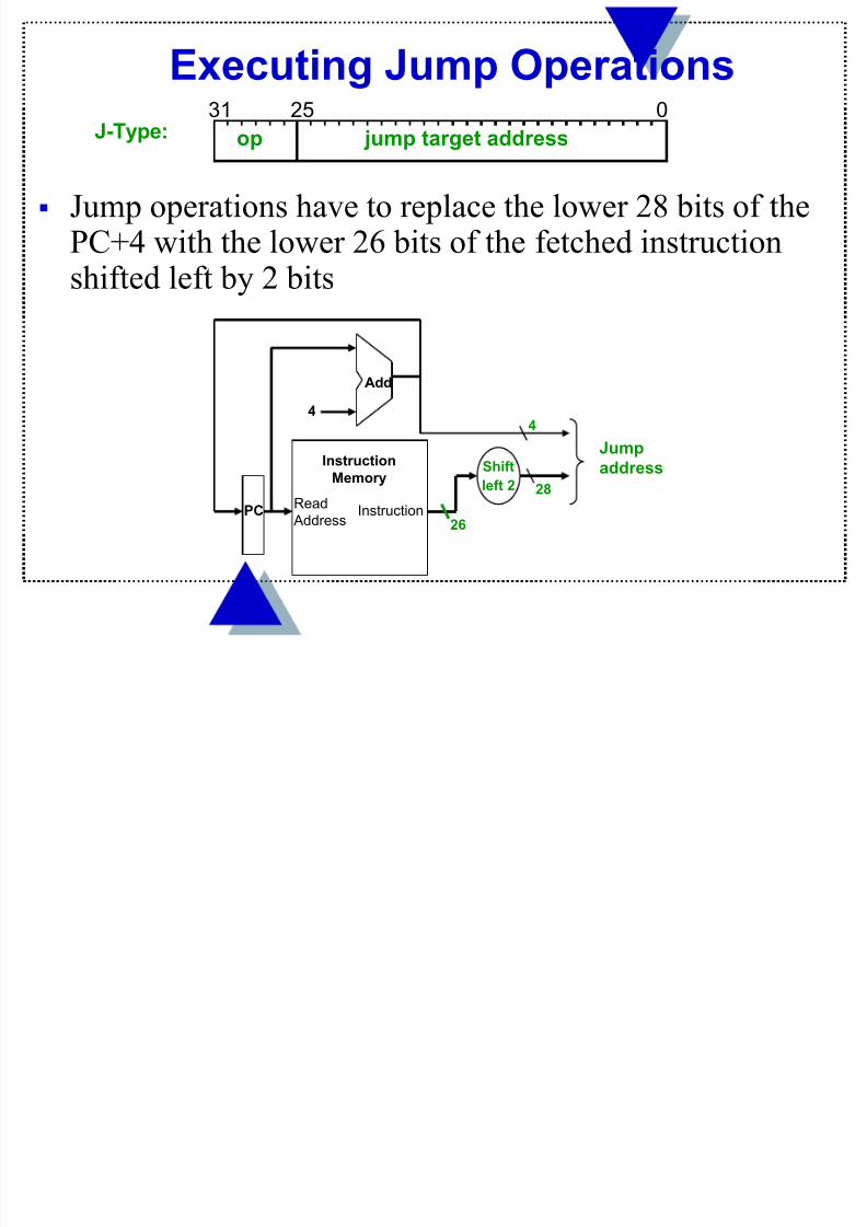
Executing Jump Operations
Jump operations have to replace the lower 28 bits of thePC+4 with the lower 26 bits of the fetched instructionshifted left by 2 bits
Read
AddressInstruction
Instruction
Memory
Add
PC
4
26
4
Shift
left 2 28
Jumpaddress
J-Type: op
31 25 0
jump target address

8/12/2019 Processor Pipelining
http://slidepdf.com/reader/full/processor-pipelining 19/144
Creating a Single Datapath from the Parts We need to assemble the datapath segments, add
control lines as needed, and design the control path Fetch, decode and execute each instruction in one
clock cycle – single cycle design. Cycle time isdetermined by length of the longest path
No datapath resource can be used more than once perinstruction, so some must be duplicated (that is whywe have a separate Instruction Memory and DataMemory)
To share datapath elements between differentinstruction classes will need multiplexors at theinput of the shared elements
Need control lines to do the selection of inputs

8/12/2019 Processor Pipelining
http://slidepdf.com/reader/full/processor-pipelining 20/144
Fetch, R, and Memory Access Portions
Read
AddressInstruction
Instruction
Memory
Add
PC
4RegWrite
ovf
zero
ALU control
ALUData
Memory
Address
Write Data
Read Data
MemWrite
MemRead
lw
R
R
Sign
Extend16 32
lw / sw
Register
File
Write Data
Read Addr 1
Read Addr 2
Write Addr
Read
Data 1
Read
Data 2

8/12/2019 Processor Pipelining
http://slidepdf.com/reader/full/processor-pipelining 21/144
Multiplexor Insertion
MemtoReg
Read
AddressInstruction
Instruction
Memory
Add
PC
4
Write Data
Read Addr 1
Read Addr 2
Write Addr
Register
File
Read
Data 1
Read
Data 2
ALU
ovf
zero
ALU controlRegWrite
DataMemory
Address
Write Data
Read Data
MemWrite
MemReadSign
Extend16 32
ALUSrc

8/12/2019 Processor Pipelining
http://slidepdf.com/reader/full/processor-pipelining 22/144
Adding the Branch Portion
Add
4 Shift
left 2
Add
Read
AddressInstruction
Instruction
Memory
PC
Write Data
Read Addr 1
Read Addr 2
Write Addr
Register
File
Read
Data 1
Read
Data 2
ALU
ovf
zero
ALU controlRegWrite
Data
Memory
Address
Write Data
Read Data
MemWrite
MemReadSign
Extend16 32
MemtoReg ALUSrc
R
lw / sw
R
lw
PCSrc
Branch not taken, R, lw /sw

8/12/2019 Processor Pipelining
http://slidepdf.com/reader/full/processor-pipelining 23/144
We wait for everything to settle down - ALU might not
produce “right answer” right away
Cycle time determined by length of the longest path
Split memory (Harvard) model - single cycle operation
Simplified to contain only the instructions: lw, sw,add, sub, and, or, slt, beq .
Sequential components (PC, RegFile, Memory) are edgetriggered - state elements are written on every clock
cycle; if not, need explicit write control signal write occurs only when both the write control is
asserted and the clock edge occurs
Datapath - review

8/12/2019 Processor Pipelining
http://slidepdf.com/reader/full/processor-pipelining 24/144
Single cycle datapath
Observations - op field always in bits 31-26
address of the two registers to be read are always specified by the rs and rt fields (bits 25-21 and 20-16)
address of register to be written is in one of two places
– in rt (bits 20-16) for lw; in rd (bits 15-11) for R -
type instructions
base register for lw and sw always in rs (bits 25-21)
offset for beq , lw, and sw always in bits 15-0
I-Type: op rs rt address offset
31 25 20 15 0
R-type:
31 25 20 15 5 0
op rs rt rd funct shamt
10

8/12/2019 Processor Pipelining
http://slidepdf.com/reader/full/processor-pipelining 25/144
(Almost) Complete Single Cycle Datapath
Read
AddressInstr[31-0]
Instruction
Memory
Add
PC
4
Write Data
Read Addr 1
Read Addr 2
Write AddrALU
ovf
zeroData
Memory
Address
Write Data
Read Data
MemWrite
MemRead
Register
File
Read
Data 1
Read
Data 2
RegWrite
Sign
Extend16 32
Shift
left 2
Add
RegDst
0
1
ALUSrc
0
1
MemtoReg
1
0
PCSrc
1
0
ALU
control
ALUOp
Instr[5-0]
Instr[15-0]
Instr[25-21]
Instr[20-16]
Instr[
15 -11]

8/12/2019 Processor Pipelining
http://slidepdf.com/reader/full/processor-pipelining 26/144
ALU's operation based on instruction type and functioncode
MIPS uses multiple control levels to increase speed ofthe main control unit and decrease its size
ALU Control
ALU control input
(Ainvert+Binvert +Operation)
Function
0000 and
0001 or
0010 add
0110 subtract
0111 set on less than
1100 NOR
set

8/12/2019 Processor Pipelining
http://slidepdf.com/reader/full/processor-pipelining 27/144
Multiple levels of control
main control unit generates the ALUOp bits
ALU control unit generates ALU controlinputs (main control is smaller)
ALU Control, continued
Instr op funct ALUOp desired action ALU control input
lw xxxxxx 00 add 0010
sw xxxxxx 00 add 0010
beq xxxxxx 01 subtract 0110
add 100000 10 add 0010
sub 100010 10 subtract 0110and 100100 10 AND 0000
or 100101 10 OR 0001
slt 101010 10 Set on less than 0111
ALU
control
ALUOp(from
control block)
Instr[5-0]
ALU control
input

8/12/2019 Processor Pipelining
http://slidepdf.com/reader/full/processor-pipelining 28/144
ALU Control Truth Table
Can make use of more don’t cares
since ALUOp does not use the encoding 11
since F5 and F4 are always 10
F5 F4 F3 F2 F1 F0 ALUOp1 ALUOp0 Op3 Op2 Op1 Op0
X X X X X X 0 0 0 0 1 0
X X X X X X x 1 0 1 1 0
X X 0 0 0 0 1 x 0 0 1 0
X X 0 0 1 0 1 x 0 1 1 0X X 0 1 0 0 1 x 0 0 0 0
X X 0 1 0 1 1 x 0 0 0 1
X X 1 0 1 0 1 x 0 1 1 1

8/12/2019 Processor Pipelining
http://slidepdf.com/reader/full/processor-pipelining 29/144
ALU Control Combinational Logic
From the truth table can design the ALU Control logic

8/12/2019 Processor Pipelining
http://slidepdf.com/reader/full/processor-pipelining 30/144
Summary of control lines
RegDest Source of the destination register for the
operation
RegWrite Enables writing a register in the register file
ALUsrc Source of second ALU operand, can be a
register or part of the instruction PCsrc Source of the PC (increment [PC + 4] or
branch)
MemRead/MemWrite Reading / Writing from datamemory
MemtoReg Source of write register contents
D t th ith C t l U it

8/12/2019 Processor Pipelining
http://slidepdf.com/reader/full/processor-pipelining 31/144
Read Addr 2
ALU
ovf
zeroData
Memory
Write Data
Address
Read Data 1
0Write Data
Read Addr 1
Write Addr
Register
File
Read
Data 1
Read
Data 2
Sign
Extend16 32
Instr[15-0]
Instr[25-21]
Instr[20-16]
Instr[15
-11]
Shift
left 2
Instr[31-0]
Add
0
1
Read
Address
Instruction
Memory
Add
PC
4
1
01
0
Instr[5-0]
Datapath with Control Unit
RegDst
Control
UnitInstr[31-26]
PCSrc
MemReadMemtoReg
MemWriteRegWrite
ALUSrc
ALU
control
ALUOpBranch

8/12/2019 Processor Pipelining
http://slidepdf.com/reader/full/processor-pipelining 32/144
Main Control Unit
Instr RegDst ALUSrc MemReg RegWr MemRd MemWr Branch ALUOp1 ALUOp0
R-
type
000000
1 0 0 1 X 0 0 1 X
lw100011 0 1 1 1 1 0 0 0 0
sw
101011X 1 X 0 X 1 0 0 0
beq000100
X 0 X 0 X 0 1 X 1

8/12/2019 Processor Pipelining
http://slidepdf.com/reader/full/processor-pipelining 33/144
Control Unit Logic From the truth table can design the Main Control logic
R-type lw sw beq
MemtoReg
MemReadMemWrite
ALUOp1
ALUOp0
Branch
ALUSrc
RegDst
RegWrite
000000 100011 101011 000100
Instr[31]Instr[30]
Instr[29]Instr[28]Instr[27]Instr[26]

8/12/2019 Processor Pipelining
http://slidepdf.com/reader/full/processor-pipelining 34/144
Adding the Jump Operation
PCSrc
0
1
Shift
left 2
0
1
Jump
32Instr[25-0]26
PC+4[31-28]
28 PC
J has the opfield 000010 followed by 26-bit jump
address. We need to add to the datapath.
The instruction bits [25-0] are shifted left two bits and
concatenated to the four MSB of PC+4.
A new multiplexer and control line are needed to select
this input for the program counter
C t l U it L i

8/12/2019 Processor Pipelining
http://slidepdf.com/reader/full/processor-pipelining 35/144
Control Unit Logic One more gate is needed in the Main Control logic for JInstr[31]Instr[30]
Instr[29]Instr[28]Instr[27]Instr[26]
RegDst
ALUSrc
MemtoReg
RegWrite
MemReadMemWrite
Branch
ALUOp1
ALUOp0
R-type lw sw beq
Jump 000010

8/12/2019 Processor Pipelining
http://slidepdf.com/reader/full/processor-pipelining 36/144
Add
0
1
ALUOpBranch
PCSrcShift
left 2
Read
Address
Write Data
Read Addr 1
Read Addr 2
Write Addr
Register
File
Read
Data 1
Read
Data 2
ALU
ovf
zero
RegWrite
Data
Memory
Address
Write Data
Read Data
MemWrite
MemRead
Sign
Extend16 32
MemtoReg
ALUSrc
RegDst
ALU
control
1
11
0
0
0
Instr[5-0]
Instr[15-0]
Instr[25-21]
Instr[20-16]
Instr[15
-11]
Control
UnitInstr[31-26]
Instr[31-0]
Instruction
Memory
Add
PC
4
PC+4[31-28]
Adding Jump Operation
Jump
0
1Shift
left 232
Instr[25-0]
2628
C l U i L i

8/12/2019 Processor Pipelining
http://slidepdf.com/reader/full/processor-pipelining 37/144
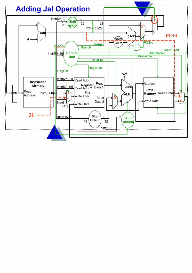
Control Unit Logic One more gate is needed in the Main Control logic forJal ( J type instruction which stores PC+4 in $ra $31)
Instr[31]Instr[30]Instr[29]Instr[28]Instr[27]Instr[26]
RegDst
MemtoReg
RegWrite
ALUOp1
ALUOp0
R-typeJal
000011000000
Jump
3 26-bit address J format
Addi J l O ti
8/12/2019 Processor Pipelining
http://slidepdf.com/reader/full/processor-pipelining 38/144
Add
0
1
ALUOpBranch
PCSrcShift
left 2
Read
Address
Write Data
Read Addr 1
Read Addr 2
Write Addr
Register
File
Read
Data 1
Read
Data 2
ALU
ovf
zero
RegWrite
Data
Memory
Address
Write Data
Read Data
MemWrite
MemRead
Sign
Extend16 32
MemtoReg
ALUSrc
RegDst
ALU
control
1
1
1
0
0
0
Instr[5-0]
Instr[15-0]
Instr[25-21]
Instr[20-16]
Instr[15-11]
Control
UnitInstr[31-26]
Instr[31-0]
Instruction
Memory
Add
PC
4
PC+4[31-28]
Adding Jal Operation
Jump
0
1Shift
left 232
Instr[25-0]
2628
PC+4
31

8/12/2019 Processor Pipelining
http://slidepdf.com/reader/full/processor-pipelining 39/144
Memto- Reg Mem Mem
RegDst ALUSrc Reg Write Read Write Branch ALUOp1 ALUOp0 Jump
R-format 01 0 00 1 0 0 0 1 0 0
lw 00 1 01 1 1 0 0 0 0 0
sw xx 1 xx 0 0 1 0 0 0 0
beq xx 0 xx 0 0 0 1 0 1 0
J xx x xx 0 0 0 x x x 1
PC Jump Address
PC+ 4R[31]
MemtoReg
Is now 2 bits
RegDst
Is now 2 bits
Adding Control line Settings for Jal Operation
JAL 10 x 10 1 0 0 x x x 1

8/12/2019 Processor Pipelining
http://slidepdf.com/reader/full/processor-pipelining 40/144
Single Cycle Implementation Cycle Time Unfortunately, though simple, the single cycle approach
is not used because it is inefficient Clock cycle must have the same length for every
instruction
What is the longest path (slowest instruction)?
Calculate cycle time assuming negligible delays (formuxes, control unit, sign extend, PC access, shift left 2,wires) except :
Instruction and Data Memory (2ns)
ALU and adders (2ns)
Register File access (reads or writes) (1ns)
floating point operations even longer

8/12/2019 Processor Pipelining
http://slidepdf.com/reader/full/processor-pipelining 41/144
Instruction Critical Paths
Instr. I Mem Reg Rd ALU Op D Mem Reg Wr Total delay
(ns)
R-type
load
store
beq
jump
2 1 2 1 6
2 1 2 2 1 8
2 1 2 2 7
2 1 2 5
2 2

8/12/2019 Processor Pipelining
http://slidepdf.com/reader/full/processor-pipelining 42/144
A floating point add.d = Instr. Fetch (2 ns)+ Reg. Read (1 ns)+ALU add(8 ns)+ Reg. Write (1 ns)= 12 ns
Floating point load l.s=2+1+2(ALUop)+2(data mem)+1 (Reg.) =8 ns
Floating point store s.s =2+1+2(ALU)+2(data mem) = 7 ns.
The longest instruction is floating point multiply mul = Inst. Fetch
(2 ns)+Reg. Read (1 ns)+ALU multiply (16 ns)+ Reg. Write (1 ns) =20 ns
Floating point branch = 5 ns, floating point jump=2 (fetch)
If clock period is variable in length, then we need to look atinstruction frequency. For example Loads (31%), stores (21%), R-type (27%), beq(5%), j (2%), add.d, sub.d (7%), mult.d, div.d(7%).
Combining to compute the clockcycle=8x31%+7x21%+6x27%+5x5%+2x2%+20x7%+12x7%=
7 ns
What about floating point operations?

8/12/2019 Processor Pipelining
http://slidepdf.com/reader/full/processor-pipelining 43/144
Instead of a fixed cycle time, we allow cycle time to depend oninstruction class.
We can then compare performance, considering that CPI will still be 1, and Instruction count does not change.
Perf. CPU variable cycle time = CPU exec. time fixed cycle time
Perf. CPU fixed cycle time CPU exec. time var. cycle time
= Clock period fixed
Clock period variable
because performance= _____________1______________ )
Instr. Count x CPI x Clock Period
Performance improvement = 20 ns (fixed cycle clock period) = 2.86 faster
7 ns (variable cycle clock period)
What about variable cycle length?

8/12/2019 Processor Pipelining
http://slidepdf.com/reader/full/processor-pipelining 44/144
Single cycle/instr. datapath is wasteful of area sincesome functional units must be duplicated since they cannot be “shared” during an instruction execution
e.g., need separate adders to do PC update and branchtarget address calculations, as well as an ALU to do R-type arithmetic/logic operations and data memoryaddress calculations
Where We are Headed Single cycle/instr. uses the clock cycle inefficiently – the
clock cycle must be timed to accommodate the slowest instruction – we cannot make common case fast.
especially problematic for more complex instructions
like floating point multiplications

8/12/2019 Processor Pipelining
http://slidepdf.com/reader/full/processor-pipelining 45/144
Is wasteful of area since some functional units must be
duplicated since they can not be shared during a clockcycle (e.g., adders, memory units)
But, it is simple(r) and easy to understand
Single Cycle Disadvantages & Advantages
Uses the clock cycle inefficiently – the clock cycle must be timed to accommodate the slowest instruction
Single Cycle Implementation:
lw sw Waste
Clk
Cycle 1 Cycle 2

8/12/2019 Processor Pipelining
http://slidepdf.com/reader/full/processor-pipelining 46/144
The Five Stages of a lw Instruction
We will consider only a subset of instructions (lw,
sw, add , sub, and , or, slt, beq )
IFetch: Instruction Fetch and Update PC
Dec: Registers Read and Instruction Decode
Exec: calculate memory address Mem: Read the data from the Data Memory
WB: Write the data back to the register file
IFetch Dec RR Exec Mem WB
Cycle 1 Cycle 2 Cycle 3 Cycle 4 Cycle 5
lw
2 ns
Wh t if

8/12/2019 Processor Pipelining
http://slidepdf.com/reader/full/processor-pipelining 47/144
What if…. Several instructions were worked on by the CPU at the “same time”
Each major logic unit works on a different stage of a different
instruction - Like doing laundry for different roommates

8/12/2019 Processor Pipelining
http://slidepdf.com/reader/full/processor-pipelining 48/144

8/12/2019 Processor Pipelining
http://slidepdf.com/reader/full/processor-pipelining 49/144
Single Cycle vs. Pipelined
Single Cycle Implementation:
Clk
Load Store Waste
Cycle 1 Cycle 2
lw IFetch Dec Exec Mem WB
Pipeline Implementation:
IFetch Dec Exec Mem WBsw
IFetch Dec Exec Mem WBR-type
wasted cycle
Pipelined lw finishes later than
non-pipelined version
Time savings
Si l C l Pi li d

8/12/2019 Processor Pipelining
http://slidepdf.com/reader/full/processor-pipelining 50/144
Single Cycle Implementation:
Pipelined Implementation:
Single Cycle, vs. Pipelined
Time savings Instruction 2
Time savings Instruction 3
Assume memory and ALU ops take 200 ps, Reg ops take 100 ps
Register read in second half of cycle

8/12/2019 Processor Pipelining
http://slidepdf.com/reader/full/processor-pipelining 51/144
What makes it easy - all instructions are the same length(32 bits) - The first two pipeline stages are the same forall instructions.
few instruction formats (three) with symmetry across
formats - registers addresses are in the same location andthus can be read while instructions are being decoded(read reg file in the first ½ of the clock cycle)
memory operations can occur only in loads and stores,
thus the ALU can compute memory addresses in EXstage
operands are aligned in memory so a single data transferrequires only one memory access
Designing MIPS Instructions for Pipelining
MIPS Pipeline Datapath Modifications

8/12/2019 Processor Pipelining
http://slidepdf.com/reader/full/processor-pipelining 52/144
MIPS Pipeline Datapath Modifications What do we need to add/modify in our single-cycle per
instruction datapath to make it pipelined?
The MIPS instruction has (up to) five stages, thus pipelienehas 5 stages:
Ifetch to fetch the instruction from Instruction memory Dec to decode the instruction and read Register File
registers Exec to do the ALU operations Mem to read from/write into Data Memory WB to write back into the register file. So we need a way to
separate the data path into five pieces, without losingintermediate results. We will introduce Pipeline registers between
stages to isolate them and store intermediate results
MIPS Pipeline Datapath Modifications

8/12/2019 Processor Pipelining
http://slidepdf.com/reader/full/processor-pipelining 53/144
Data
Memory Address
Write Data
Read
Data
M
e m / W B
System Clock
MIPS Pipeline Datapath Modifications
ALU
1
0
Shiftleft 2
Add
E x
e c / M e m 1
0
All instructions advance during one clock cycle between one pipeline register and the next
IF (fetch) EX (execute) Mem WB
(write back)
Read
Address
Instruction
Memory
Add
P C
4
0
1
I F e t c h / D e c
Read
Data 2
16
Read Addr 1
Write Addr
Write Data
Read Addr 2
Register
File
Read
Data 1
32
D e c / E x e c
ID (decode)
Sign
Extend
MIPS Pipeline Datapath Modifications

8/12/2019 Processor Pipelining
http://slidepdf.com/reader/full/processor-pipelining 54/144
MIPS Pipeline Datapath Modifications Because all data is passed through the pipeline, the address of the
register where data needs to be loaded (lw) also needs to be passedIFetch
System Clock
Read
Address
Instruction
Memory
Add
P C
4
0
1
I F e t c h / D e c
1
0
Read
Data 2
16
Read Addr 1
Write Addr
Write Data
Read Addr 2
Register
File
Read
Data 1
32
D e c / E x e c
Sign
Extend
Data
Memory Address
Write Data
Read
Data
M e m / W B
ALU
1
0
Shiftleft 2
Add
E x e c / M e m
Dec Exec Mem WB
Pipeline Register size (for now)
IF/ID 64
ID/EX 32x4+5=133
EX/MEM 32x3+5=101
MEM/WB 32x2=5=69
Extends pipeline reg. to hold address of destination reg.
MIPS Pipeline Control Path Modifications

8/12/2019 Processor Pipelining
http://slidepdf.com/reader/full/processor-pipelining 55/144
IFetch
Data
Memory Address
Write Data
Read
Data
M
e m / W B
Read
Address
Instruction
Memory
Add
P C
4
0
1
I F e t c h / D e c
System Clock
1
0
ALU
1
0
Shiftleft 2
Add
E x
e c / M e m
Read
Data 2
16
Read Addr 1
Write Addr
Write Data
Read Addr 2
Register
File
Read
Data 1
32
D e c / E x e c
Sign
Extend
MIPS Pipeline Control Path Modifications All control signals are determined during Decode and held in the pipeline registers between pipeline stages
Dec
Control
Exec Mem WB
MIPS Pipeline Control Path Modifications

8/12/2019 Processor Pipelining
http://slidepdf.com/reader/full/processor-pipelining 56/144
MIPS Pipeline Control Path Modifications
The modifiedcontrol path is
6
2
4
3
Pipeline Example

8/12/2019 Processor Pipelining
http://slidepdf.com/reader/full/processor-pipelining 57/144
Pipeline Example
How does the non-dependent instruction sequence
execute in a pipeline ? (no support for forwarding) before <4>
before <3>
before <2>
before <1>
lw $10, 20($1)
sub $11, $2, $3
and $12, $4, $5
or $13, $6, $7
add $14, $8, $9after <1>
after <2>
Pi li E l b f <4> l t

8/12/2019 Processor Pipelining
http://slidepdf.com/reader/full/processor-pipelining 58/144
Pipeline Example - before <4> completes
Pipeline E ample b f <3> l t

8/12/2019 Processor Pipelining
http://slidepdf.com/reader/full/processor-pipelining 59/144
Pipeline Example - before <3> completes

8/12/2019 Processor Pipelining
http://slidepdf.com/reader/full/processor-pipelining 60/144
Pi li E l b f <1> l t

8/12/2019 Processor Pipelining
http://slidepdf.com/reader/full/processor-pipelining 61/144
Pipeline Example - before <1> completes
3
11
$4, $5
Pipeline Example l completes

8/12/2019 Processor Pipelining
http://slidepdf.com/reader/full/processor-pipelining 62/144
Pipeline Example - lw completes
12
$5
destination register
D a t a m e m o r y n
o t u s e d
( M E M
c o n t r o l l i n e s 0 )
Pipeline Example sub completes

8/12/2019 Processor Pipelining
http://slidepdf.com/reader/full/processor-pipelining 63/144
13
$7
Pipeline Example - sub completes
D a t a m e m o r y n
o t u s e d
( M E M
c o n t r o l l i n e s 0 )
$6, $7
Pipeline Example and completes

8/12/2019 Processor Pipelining
http://slidepdf.com/reader/full/processor-pipelining 64/144
Pipeline Example - and completes
$9
14
N o r m a l P C + 4 i n c r e m e n t
( P C S r c = 0 )
Pipeline Example or completes

8/12/2019 Processor Pipelining
http://slidepdf.com/reader/full/processor-pipelining 65/144
Pipeline Example - or completes
Pipeline Example add completes

8/12/2019 Processor Pipelining
http://slidepdf.com/reader/full/processor-pipelining 66/144
Pipeline Example - add completes
Written in first half of cycle
G hi ll R ti MIPS Pi li

8/12/2019 Processor Pipelining
http://slidepdf.com/reader/full/processor-pipelining 67/144
So-far we saw the single-clock-cycle pipeline diagrams – show the state of the entire datapath during a clockcycle (instructions are identified above the pipeline
stages). Multi-clock-cycle pipeline diagrams are simpler, andcan help answer how many cycles does it take toexecute this code
Or what is the ALU doing during a certain cycle Can represent multiple instructions in a single figure If there is a hazard, it shows why it occurs, and how it
can be fixed
Graphically Representing MIPS Pipeline
IM Reg Reg
AL U
DM
Why Pipeline? For Throughput!

8/12/2019 Processor Pipelining
http://slidepdf.com/reader/full/processor-pipelining 68/144
Why Pipeline? For Throughput!Time (clock cycles)
I
n
s
t
r.
O
r
d
e
r
Inst 0AL U
IM Reg DM Reg
Inst 1AL U
IM Reg DM Reg
Inst 2AL U
IM Reg DM Reg
Inst 3AL U
IM Reg DM Reg
Inst 4AL U
IM Reg DM Reg
O n c e
t h e
p i p e
l i n e
i s
f u
l l ,
o n e
i n s
t r u c
t i o n
i s
c o m p
l e
t e
d
e v e r y
c y c
l e
Time to fill the pipeline
Example of graphical representation

8/12/2019 Processor Pipelining
http://slidepdf.com/reader/full/processor-pipelining 69/144
Example of graphical representation
M
Can be converted in a
single-clock-cycle
pipeline diagram
DM
Example of single-clock-cycle (cc 5)

8/12/2019 Processor Pipelining
http://slidepdf.com/reader/full/processor-pipelining 70/144
Example of single clock cycle (cc 5)
pipeline representation
Pipelining the MIPS ISA

8/12/2019 Processor Pipelining
http://slidepdf.com/reader/full/processor-pipelining 71/144
What makes it hard - structural hazards: what ifwe had only one memory - then the pipeline cannot have
one instruction read from memory (fetch stage), while atthe same time another instruction writes into memory (sw)
control hazards: need to make a decision based onthe results of one instruction, while that instruction is still
executing. what about branches?
pe g t e S S
Stalling
Impact of branch stalling

8/12/2019 Processor Pipelining
http://slidepdf.com/reader/full/processor-pipelining 72/144
We assume that all instructions in the pipeline have a
CPI of 1. Branches which always are followed by a stall
have a CPI of 2.
In a typical program branches occur 13% of the time.
Thus we can compute the aggregate CPI of the always-
stall for branch architecture as:
Impact of branch stalling
Then CPI = Σ CPI i x F ii=1
n
CPI always stall = 1 x 87% + 2 x 13% = 1.13 cycles/instruction
Thus CPU Perform. always stall = Inst. Count x CPI no stall x ClockPerform. no stall Inst. CountxCPI always stall x Clock
Perform. always stall = 1 = 0.885 ( 88.5%)
Perform. no stall 1.13
Pipelining the MIPS ISA

8/12/2019 Processor Pipelining
http://slidepdf.com/reader/full/processor-pipelining 73/144
control hazards: Another approach is “prediction” - either static - always execute the instruction following a branch (assumealways that the branch is not taken), or predict dynamically (keep ahistory of each branch as taken or not taken - accurate 90% of time).
Pipelining the MIPS ISA
Branch not taken
Branch taken
Pipelining the MIPS ISA

8/12/2019 Processor Pipelining
http://slidepdf.com/reader/full/processor-pipelining 74/144
data hazards: what if an instruction’s input operands
depend on the output of a previous instruction that did notfinish? Example an add followed by a sub.
Pipelining the MIPS ISA
Forwarding
The pipeline simplified representation is shading the
blocks that are used in a given clock cycle.
Pipelining the MIPS ISA

8/12/2019 Processor Pipelining
http://slidepdf.com/reader/full/processor-pipelining 75/144
Pipelining the MIPS ISA
Forwarding will fail for a lw followed immediately by
an instruction that uses the results of the lw operation.
Example lw followed by a sub.

8/12/2019 Processor Pipelining
http://slidepdf.com/reader/full/processor-pipelining 76/144

8/12/2019 Processor Pipelining
http://slidepdf.com/reader/full/processor-pipelining 77/144
How About Register File Access?
I
n
s
t
r.
O
r
d
er
Time (clock cycles)
add
Inst 1
Inst 2
Inst 4
add
AL U
IM Reg DM Reg
AL
U IM Reg DM Reg
AL U
IM Reg DM Reg
AL
U
IM Reg DM Reg
AL U
IM Reg DM Reg
Can fix register file
access hazard by
doing reads in the
second half of the
cycle and writes in
the first half.
Branch Instructions Cause Control Hazards

8/12/2019 Processor Pipelining
http://slidepdf.com/reader/full/processor-pipelining 78/144
Branch Instructions Cause Control Hazards
I
n
s
t
r.
O
r
d
e
r
add
beq
lw
Inst 4
Inst 3
AL U
IM Reg DM Reg
AL U
IM Reg DM Reg
AL U
IM Reg DM Reg
AL
U IM Reg DM Reg
AL U
IM Reg DM Reg
Dependencies backward in time cause hazards time
One Way to “Fix” a Control Hazard

8/12/2019 Processor Pipelining
http://slidepdf.com/reader/full/processor-pipelining 79/144
One Way to Fix a Control Hazard
I
ns
t
r.
O
r
d
e
r
add
beq
AL U
IM Reg DM Reg
AL U
IM Reg DM Reg
Inst 3
lw
AL
U IM Reg DM Reg
AL U
IM Reg DM Reg
Can fix branch
hazard by waiting –
stall – but affects
throughput
stall
stall
Register Usage Can Cause Data Hazards

8/12/2019 Processor Pipelining
http://slidepdf.com/reader/full/processor-pipelining 80/144
I
n
s
t
r.
O
r
d
er
No data hazard
Register Usage Can Cause Data Hazards
add r1,r2,r3AL U
IM Reg DM Reg
sub r4,r1,r5AL
U IM Reg DM Reg
and r6,r1,r7AL U
IM Reg DM Reg
or r8, r1, r9
AL
U
IM Reg DM Reg
xor r4,r1,r5AL U
IM Reg DM Reg
Dependencies backward in time cause hazards
Data hazard
O W “Fi ” D H d

8/12/2019 Processor Pipelining
http://slidepdf.com/reader/full/processor-pipelining 81/144
One Way to “Fix” a Data Hazard
I
n
s
t
r.
O
r
d
e
r
add r1,r2,r3AL U
IM Reg DM Reg
sub r4,r1,r5
and r6,r1,r7
AL U
IM Reg DM Reg
AL U
IM Reg DM Reg
stall
stall
Can fix data hazard
by waiting –
stall –
but affects
throughput
Loads Can Cause Data Hazards

8/12/2019 Processor Pipelining
http://slidepdf.com/reader/full/processor-pipelining 82/144
Loads Can Cause Data Hazards
I
n
s
t
r.
O
r
d
e
r
lw r1,100(r2)
sub r4,r1,r5
and r6,r1,r7
xor r4,r1,r5
or r8, r1, r9
AL U
IM Reg DM Reg
AL U
IM Reg DM Reg
AL U
IM Reg DM Reg
AL U
IM Reg DM Reg
AL U
IM Reg DM Reg
Dependencies backward in time cause hazards
Stores Can Cause Data Hazards

8/12/2019 Processor Pipelining
http://slidepdf.com/reader/full/processor-pipelining 83/144
Stores Can Cause Data Hazards
I
n
s
t
r.
O
r
d
e
r
add r1,r2,r3
sw r1,100(r5)
and r6,r1,r7
xor r4,r1,r5
or r8, r1, r9
AL U
IM Reg DM Reg
AL U
IM Reg DM Reg
AL U
IM Reg DM Reg
AL U
IM Reg DM Reg
AL U
IM Reg DM Reg
Dependencies backward in time cause hazards
Pipeline Changes to

8/12/2019 Processor Pipelining
http://slidepdf.com/reader/full/processor-pipelining 84/144
Pipeline Changes to
accommodate Forwarding To avoid slowing down throughput, we need to add a hardware
that detects data hazards. We call this the forwarding unit.
Data needs to be forwarded to the ALU when a data hazard isdetected. Thus the forwarding unit controls forwarding data
through additional multiplexing at the ALU input.
This logic unit needs input from the three pipeline registers.
It also needs to detect if the RegWrite control signal is asserted
– so it needs input from the control lines also.
No forwarding if EX/MEM.RegisterRd=$0 and
MEM/WB.RegisterRd=$0
Pipeline Changes to accommodate Forwarding

8/12/2019 Processor Pipelining
http://slidepdf.com/reader/full/processor-pipelining 85/144
Pipeline Changes to accommodate Forwarding
It needs to detect one of four cases of data hazards:
if (EX/MEM.RegWrite
and (EX/MEM.RegisterRd 0
and (EX/MEM.RegisterRd=ID/EX.RegisterRs) Forward
similarly
if (EX/MEM.RegWrite
and (EX/MEM.RegisterRd 0
and (EX/MEM.RegisterRd=ID/EX.RegisterRt) Forward
Pipeline Changes to accommodate Forwarding

8/12/2019 Processor Pipelining
http://slidepdf.com/reader/full/processor-pipelining 86/144
Pipeline Changes to accommodate Forwarding
similarly
if (MEM/WB.RegWrite
and (MEM/WB.RegisterRd 0
and (MEM/WB.RegisterRd=ID/EX.RegisterRs) Forward
similarly
if (MEM/WB.RegWrite
and (MEM/WB.RegisterRd 0
and (MEM/WB.RegisterRd=ID/EX.RegisterRt) Forward
Using Pipeline Registers to solve data hazards

8/12/2019 Processor Pipelining
http://slidepdf.com/reader/full/processor-pipelining 87/144
g p g

8/12/2019 Processor Pipelining
http://slidepdf.com/reader/full/processor-pipelining 88/144
Pipeline Changes to accommodate Forwarding

8/12/2019 Processor Pipelining
http://slidepdf.com/reader/full/processor-pipelining 89/144
22
0
1
2
0
1
2
ForwardA 00 ID/EX input to ALU1 - no fwd
01 MEM/WB input to ALU1
10 EX/MEM input to ALU1
ForwardB 00 ID/EX input to ALU2
01 MEM/WB input to ALU2
10 EX/MEM input to ALU2
ForwardB 11 sign extension
input to ALU2
OR add another multiplexer
ALUSrc
0
1
Forwarding Pipeline Example

8/12/2019 Processor Pipelining
http://slidepdf.com/reader/full/processor-pipelining 90/144
Forwarding Pipeline Example
How does the dependent instruction sequence execute in
a pipeline with support for forwarding? before <4>
before <3>
before <2>
before <1>sub $2, $1, $3
and $4, $2, $5
or $4, $4, $2
add $9, $4, $2
after <1>
after <2>
…
Forw. Pipeline Example - before <2> completes

8/12/2019 Processor Pipelining
http://slidepdf.com/reader/full/processor-pipelining 91/144
p p p
Forw. Pipeline Example - before <1> completes

8/12/2019 Processor Pipelining
http://slidepdf.com/reader/full/processor-pipelining 92/144
EX/MEM.RegisterRd=ID/EX.RegisterRs
Use this value of $2 not the one fetched
from register file
EX/MEM.RegWrite isasserted
Forw. Pipeline Example - sub completes

8/12/2019 Processor Pipelining
http://slidepdf.com/reader/full/processor-pipelining 93/144
p
EX/MEM.RegisterRd=ID/EX.RegisterRs MEM/WB.RegisterRd=ID/EX.RegisterRt
Both $4 and $2 are forwardedEX/MEM.RegWrite isasserted
MEM/WB.RegWritis asserted
Forwarding Pipeline Example - and completes

8/12/2019 Processor Pipelining
http://slidepdf.com/reader/full/processor-pipelining 94/144
EX/MEM.RegisterRd=ID/EX.RegisterRs
EX/MEM.RegWrite isasserted
Use this value of $4 not the one fetched
from register file

8/12/2019 Processor Pipelining
http://slidepdf.com/reader/full/processor-pipelining 95/144
Example (corrected)

8/12/2019 Processor Pipelining
http://slidepdf.com/reader/full/processor-pipelining 96/144
p ( )
Example (corrected)

8/12/2019 Processor Pipelining
http://slidepdf.com/reader/full/processor-pipelining 97/144
p ( )
Example (corrected)

8/12/2019 Processor Pipelining
http://slidepdf.com/reader/full/processor-pipelining 98/144
p ( )
Example (corrected)

8/12/2019 Processor Pipelining
http://slidepdf.com/reader/full/processor-pipelining 99/144
p ( )
Example (corrected)

8/12/2019 Processor Pipelining
http://slidepdf.com/reader/full/processor-pipelining 100/144
p ( )
Pipeline Changes to accommodate Stalls Forwarding does not work when an instruction following a lw

8/12/2019 Processor Pipelining
http://slidepdf.com/reader/full/processor-pipelining 101/144
Forwarding does not work when an instruction following a lw tries to read the value from the destination register of lw
lw $2 , 20($1)
and $4, $2 , $5or $8, $2 , $6
The pipeline needs to be stalled, and data forwarded from the
MEM/WB pipeline register
Forwarding does not work
How Stalls are insertedStalls happen in the EX stage such that the subsequent

8/12/2019 Processor Pipelining
http://slidepdf.com/reader/full/processor-pipelining 102/144
Stalls happen in the EX stage, such that the subsequent
two instructions in the pipeline both repeat what they
were doing for one cycle This allows forwarding to work
Stall in CC4 and and or repeat what they did in
CC3
OR is fetched in CC3 but it stays in
ID stage for another cycle
Pipeline Changes to accommodate Stalls

8/12/2019 Processor Pipelining
http://slidepdf.com/reader/full/processor-pipelining 103/144
We need a logic unit which detects hazards and then stalls.
The hazard detection unit operates in the instruction
decode stage, and tests to see if the instruction is a load (ifID/EX.MemRead control line is asserted)
Then it checks if either of the source registers of the instructioncurrently being decoded is the same as the target/destinationregister of the lw being executed (that is ifID/EX.RegisterRt=IF/ID.RegisterRs or
ID/ EX.RegisterRt= IF/ID.RegisterRt)
During stalling the PC is prevented from incrementing and theinstruction in the IF/ID pipeline register is preserved. Need
additional control lines for the IF/ID register and for the PC. The bubble is inserted by setting the pipelined control signals in
the ID/EX pipeline register to 0. So we need a way to change thevalues of the control lines.
Pipeline Changes to do Hazard Detection

8/12/2019 Processor Pipelining
http://slidepdf.com/reader/full/processor-pipelining 104/144
I n s t r u c t i o n s o u r c e r e g i s t e r s
I D / E X . R e g i s t e r R
t
Pipeline Changes to do Hazard Detection

8/12/2019 Processor Pipelining
http://slidepdf.com/reader/full/processor-pipelining 105/144
I F / I D w
r i t e
P C w r i t e
Stall by 0-ing all 9 control lines
Pipeline stalling example before<3> completes

8/12/2019 Processor Pipelining
http://slidepdf.com/reader/full/processor-pipelining 106/144

8/12/2019 Processor Pipelining
http://slidepdf.com/reader/full/processor-pipelining 107/144
Pipeline stalling example before<1> completesPCWrite

8/12/2019 Processor Pipelining
http://slidepdf.com/reader/full/processor-pipelining 108/144
0
0
Bubble inserted
Registers continue to be read
IF/IDWrite
is asserted
PCWrite
is asserted
Pipeline stalling example lw completes

8/12/2019 Processor Pipelining
http://slidepdf.com/reader/full/processor-pipelining 109/144
Forwarding unit sets ALUsrc multiplexer to use value from WB register
Pipeline stalling example bubble completes

8/12/2019 Processor Pipelining
http://slidepdf.com/reader/full/processor-pipelining 110/144
Forwarding unit sets ALUsrc multiplexer to use value from EX/MEM register
Consider executing the following code
Example

8/12/2019 Processor Pipelining
http://slidepdf.com/reader/full/processor-pipelining 111/144
Consider executing the following codeadd $5, $6, $7lw $6 , 100($7)sub $7, $6 , $8
How many cycles will it take to execute the code? Draw a diagram thatillustrates the dependencies that need to be resolved
CC 7 CC 8
add $5,$6,$7
lw $6,100($7)
sub $7, $6, $8

8/12/2019 Processor Pipelining
http://slidepdf.com/reader/full/processor-pipelining 112/144
MIPS Pipeline Control Path Modifications

8/12/2019 Processor Pipelining
http://slidepdf.com/reader/full/processor-pipelining 113/144
6
2
3 Branch decision in MEM stage
Pipeline Changes to accommodate Control Hazards
Control hazards are due to branch hazards and to exceptions (I/O

8/12/2019 Processor Pipelining
http://slidepdf.com/reader/full/processor-pipelining 114/144
interrupts, requests from the OS, overflow, or an unknowninstruction).
A branch hazard occurs less frequently than data hazards, andis detected in the MEM stage of the pipeline.
Assume branch not taken, the three instructions following a branchthat is taken will be in the pipeline, and need to be flushed.
40 beq $1,$3,7
44 and $12,$2,$5
48 or $13,$6,$2
52 add $14,$2,$2
56 …
72 lw $4,50($7)
branch detected CC4
Pipeline Changes to accommodate Branch Hazards
The pipeline throughput can be improved by moving the

8/12/2019 Processor Pipelining
http://slidepdf.com/reader/full/processor-pipelining 115/144
The pipeline throughput can be improved by moving thedecision whether the branch is taken or not to the
Decode stage of the pipeline; Then if the branch is taken, only one instructionneeds to be flushed (discarded) - the instructionimmediately after the branch instruction.
Thus we need a new logic circuit which compares thecontents of the register file outputs; Since the decision is taken in the decode stage, the
branch address needs to be computed in the decode phase too, in case the branch is to be taken
Thus we need a new adder in the decode phase, aswell as add an IF Flush control line to flush theIF/ID pipeline register.
Pipeline Changes to accommodate Branch Hazards
Branch

8/12/2019 Processor Pipelining
http://slidepdf.com/reader/full/processor-pipelining 116/144
Compute branch address Check for equality
S w i t c h t o b r a n c h a
d d r e s s
Pipelined branch example <before 2> completes

8/12/2019 Processor Pipelining
http://slidepdf.com/reader/full/processor-pipelining 117/144
2
Branch
I F F l u s h
P C - r e l a t i v e b r a n c h 4 0 + 4 + 7 *
4 = 7 2
Flushing means instruction field is 0s
Pipelined branch example <before 1> completes

8/12/2019 Processor Pipelining
http://slidepdf.com/reader/full/processor-pipelining 118/144
3
Pipeline Changes to accommodate Branch Hazards
The above scheme will fail if we have the following

8/12/2019 Processor Pipelining
http://slidepdf.com/reader/full/processor-pipelining 119/144
The above scheme will fail if we have the following
series of instructions:
36 add $1, $6, $7
40 beq $1, $3, 28
44 and $12, $2, $5
… 72 lw…
Because the correct value of register $1 is not in the
decode stage (in the register file) at the time when the
comparator needs it Pipeline needs to be stalled and the value of $1 needs to
be forwarded from EX/Mem pipeline register
Pipeline Changes to accommodate Branch Hazards

8/12/2019 Processor Pipelining
http://slidepdf.com/reader/full/processor-pipelining 120/144
36 add $1, $6, $7
40 beq $1, $3, 28
44 and $12, $2, $5
…
72 lw…
Pipeline Changes to accommodate Branch Hazards

8/12/2019 Processor Pipelining
http://slidepdf.com/reader/full/processor-pipelining 121/144
Stall
36 add $1, $6, $7
40 beq $1, $3, 28
…
72 lw…
flush
Pipeline Changes to accommodate Branch Hazards

8/12/2019 Processor Pipelining
http://slidepdf.com/reader/full/processor-pipelining 122/144
How can the following code be modified to make use of a delayed
Example

8/12/2019 Processor Pipelining
http://slidepdf.com/reader/full/processor-pipelining 123/144
branch slot?:Loop: lw $2, 100($3)
addi $3, $3, 4 beq $3, $4, Loop
We cannot put addi after the beq since it modifies register $3
We cannot just put lw after the beq since register $3 had changed
First we re-write the code asLoop: addi $3, $3, 4
lw $2, 96($3) beq $3, $4, Loop
Then we can move the lw after the beq
Loop: addi $3, $3, 4 beq $3, $4, Looplw $2, 96($3)
How can the following code be modified to make use of a delayed
Example

8/12/2019 Processor Pipelining
http://slidepdf.com/reader/full/processor-pipelining 124/144
branch slot?:Loop: lw $2, 100($3)
addi $3, $3, 4 beq $3, $4, Loop
We cannot put addi after the beq since it modifies register $3
We cannot just put lw after the beq since register $3 had changed
First we re-write the code asLoop: addi $3, $3, 4
lw $2, 96($3) beq $3, $4, Loop
Then we can move the lw after the beq
Loop: addi $3, $3, 4 beq $3, $4, Looplw $2, 96($3)
Consider the pipelined datapath that does not accommodate branch
Example 2

8/12/2019 Processor Pipelining
http://slidepdf.com/reader/full/processor-pipelining 125/144
Consider the pipelined datapath that does not accommodate branch
hazards. Can an attempt to flush and an attempt to stall occur
simultaneously? You may want to consider the following codesequence to help you answer this question: beq $1, $2, TARGET #assume the branch
is takenlw $3, 40($4)
add $3, $3, $3sw $3, 40($4)TARGET: or $10,$11, $12
If the beq resolution is in the MEM stage, and the branch is taken,
it requires a flush of the IF/ID pipeline register (means the registerneeds to be written to) and a change of the PC to the branch
address; this happens in clock cycle 4.
At the same time a hazard is detected between lw and the
Example 2 - continued

8/12/2019 Processor Pipelining
http://slidepdf.com/reader/full/processor-pipelining 126/144
At the same time a hazard is detected between lw and thenext instruction (add ) which is dependent (due to $3
used as source register). Thus the hazard detection unitissues a stall, and requests that the PC and the IF/IDregisters not be written to. The answer is YES, a flushand a stall are issued simultaneously.
If there are any conflicting actions, which should take priority?
Flush should take priority
Is there a simple change you can make to the datapath to
ensure the necessary priority?
The hazard detection unit should be changed to see the
Example 2- continued

8/12/2019 Processor Pipelining
http://slidepdf.com/reader/full/processor-pipelining 127/144
The hazard detection unit should be changed to see theRegWrite signal in the execution stage after it goes
through the MUX used to flush the pipelineRegWrite
Dynamic branch prediction The static branch “predicts” that it will not be taken and

8/12/2019 Processor Pipelining
http://slidepdf.com/reader/full/processor-pipelining 128/144
The static branch predicts that it will not be taken and
then flush if it was taken works for simple pipelines, but
is wasteful for performance for aggressive pipeliningarchitecture (such as the multiple issue of Pentium IV).
One approach is to have a branch prediction buffer (a
small memory unit indexed by the lower portion of the
address in the branch instruction). It contains a bit that
says if the branch was recently taken or not.
The value of the prediction bit is inverted if the
prediction turned out to be wrong. When the branch is
almost always taken, this 1-bit predictor will predict
wrong twice (at the start and end of the run of branches).
Dynamic branch prediction A better approach is to use a two-bit scheme, which must be wrong twice to
h th di ti f di ti

8/12/2019 Processor Pipelining
http://slidepdf.com/reader/full/processor-pipelining 129/144
change the direction of prediction. The branch prediction is stored in a special buffer which is accessed with the beq instruction in the IF stage. If the beq is predicted as taken, then fetching begins from the target once beq is in ID.
Not Taken
Taken
Not Taken
Taken
Not TakenTaken
Further optimization with a global predictor taking into consideration the global behavior of recently executed branches. Each branch has two predictors, andtournament predictor keeps track and favors the one that was more accurate.
Dynamic branch prediction with compiler optimization
Furthermore, compilers place instructions that always execute in the“dela spot”

8/12/2019 Processor Pipelining
http://slidepdf.com/reader/full/processor-pipelining 130/144
Best choice For mostly taken branches“delay spot”
Pipeline Changes to accommodate Exceptions Overflow is discovered at the end of the execute stage when the
ALU d i l h l i

8/12/2019 Processor Pipelining
http://slidepdf.com/reader/full/processor-pipelining 131/144
8000180
ALU sends a signal to the control unit.
Following notification of an overflow the control unit has to flush
the two instructions that followed the one causing the overflow.
These instructions are now in the IF and ID stages of the pipeline.
Thus we add an input to the MUX in the ID stage that 0s the
control signals using an ID.Flush signal
IF.Flush
ID.Flush
Overflow
Pipeline Changes to accommodate Exceptions
The instruction that causes the overflow (which is detected in the

8/12/2019 Processor Pipelining
http://slidepdf.com/reader/full/processor-pipelining 132/144
The instruction that causes the overflow (which is detected in theEX stage) needs to be flushed from the pipeline. This means that
an EX.Flush signal needs to be sent to two multiplexers to zerothe control signals for the last two stages of the pipeline.
Overflow is only one of the many possible exception causes. Thecause is stored in a Cause register below:
4 – address error exception (load)
5- address error exception (store) 10 – unknown instructions or reserved instruction
12 – arithmetic overflow
15 – floating point exception
Pipeline Changes to accommodate Exceptions An additional input is added to the PC MUX that sends to the PC

8/12/2019 Processor Pipelining
http://slidepdf.com/reader/full/processor-pipelining 133/144
8000 0180hex (system reserved memory address for overflow)
The address of the instruction following the offending command issaved in the Exception Program Counter (EPC) registerand the cause in the Cause Register.
If there are multiple exceptions, their causes are stored in the causeregister, such that hardware can interrupt based on later exceptions
once the earliest exception has been serviced. In case of an I/o interrupt, the execution jumps to the system routine
needed to deal with the I/o, followed by a return to the address storedin the EPC for program completion.
The OS responds to an exception either by terminating the processthat caused the exception or by performing some action.
The process who’s exception is due to an unimplemented instructionis killed by the OS.
Branch
Pipeline Changes to accommodate Overflow
EX.Flush

8/12/2019 Processor Pipelining
http://slidepdf.com/reader/full/processor-pipelining 134/144
0
0
EX.Flush
80000180
Overflow
Branch
Pipeline Changes to accommodate Unknown Instruction
EX.Flush (LOW)

8/12/2019 Processor Pipelining
http://slidepdf.com/reader/full/processor-pipelining 135/144
0
0
( )
80000180
Pipelined exception example: and completes

8/12/2019 Processor Pipelining
http://slidepdf.com/reader/full/processor-pipelining 136/144
50 add causes an overflow
Overflow
54
80000180
Pipelined exception example or completesOS instruction fetched

8/12/2019 Processor Pipelining
http://slidepdf.com/reader/full/processor-pipelining 137/144
80000180
80000180
80000184
80000184

8/12/2019 Processor Pipelining
http://slidepdf.com/reader/full/processor-pipelining 138/144
Static Multiple Issue
U d i b dd d d VLIW

8/12/2019 Processor Pipelining
http://slidepdf.com/reader/full/processor-pipelining 139/144
Used in embedded processors and VLIW processors
Can improve performance by up to 200%
Layout is restricted to simplify the decoding and instruction issue
Instructions are issued in pairs, aligned on a 64-bit boundary with
the ALU and branch portion operating first;
If one of the instruction of the pair cannot be used, it is replaced by ano-op.
The hardware detects data hazards and generates stalls between two
issue packets, but the compiler is required to avoid all dependencies
within the instruction pair.
A load will cause the next two instructions to stall if they were to
use the loaded word.
CC 7 CC 8

8/12/2019 Processor Pipelining
http://slidepdf.com/reader/full/processor-pipelining 140/144
add …
lw
beq …
sw
sub …
lw …
Static two-issue datapath We need two output ports for Instruction memory, two more read
and one more write ports for the Register file two ALUs (one

8/12/2019 Processor Pipelining
http://slidepdf.com/reader/full/processor-pipelining 141/144
and one more write ports for the Register file, two ALUs (onehandles address computation for Data memory access), and two
sign-extending units

8/12/2019 Processor Pipelining
http://slidepdf.com/reader/full/processor-pipelining 142/144
AMD Opteron X4 12-stage pipeline
Speculative pipeline that executes
3 instructions/clock cycle

8/12/2019 Processor Pipelining
http://slidepdf.com/reader/full/processor-pipelining 143/144
Speculative pipeline that executes 3 instructions/clock cycle
Register renaming removes anti-
dependencies. In case of incorrect
speculation, the mapping between
architectural and physical registers is
undone.
Memory address calculation
Actual memory access
Intel Core pipeline

8/12/2019 Processor Pipelining
http://slidepdf.com/reader/full/processor-pipelining 144/144
Each core can execute 4
instructions
simultaneously
A Core duo can execute 8
instructions
simultaneouslyBetter branch prediction
Enhanced ALU
Less power consumption