Processing of High Strength Superalloy Components … · PROCESSING OF HIGH STRENGTH SUPERALLOY...
10
PROCESSING OF HIGH STRENGTH SUPERALLOY COMPONENTS FROM FINE GRAIN INGOT P. D. Genereux and D. F. Paulonis Materials Engineering Pratt & Whitney 400 Main Street East Hartford, CT 06108 Abstract The utilization of high strength superalloys, such as MERL 76, for crit- tical gas turbine engine disks was made possible by the emergence of powder metallurgy technology. This paper clearly demonstrates that it is now possi- ble to produce these superalloy components from fine grain ingot, without the need for powder. Potential advantages are lower cost and improved clean- liness (properties). Several alternative process methods are described, which incorporate either specialized thermal treatments and/or extrusion prior to forging. Work to date indicates that the processability and mechan- ical properties of parts made from fine grain ingot are at least equivalent to those made by powder metallurgy methods. Introduction Nickel-base superalloys are used for many critical compressor and tur- bine components in gas turbine engines. As engine performance and durability have increased in response to market pressures, the materials used for crit- ical parts (e.g., disks and seals) have also had to be improved. This has been achieved by changing the basic character of the superalloys used. In the 1960's, the most common disk material was the intermediate strength alloy Waspaloy, which contains about 20 volume percent of the hardening phase, gamma prime (1). During the late 1960's and 1970's, new higher strength alloys IN100 and its derivative MERL 76 were developed for disks in the FlOO and PW2037. The concentration of gamma prime was now much higher t-65%), which was achieved by large increases in alloy element content and complexity. These changes made it impossible to process alloys by the con- ventional VIM/VAR (vacuum induction melt/vacuum arc remelt) ingot and forg- ing sequences used for Waspaloy due to segregation and cracking problems. The problems were solved by the development of inert gas powder atomization processes, effective consolidation (hot isostatic pressing or extrusion) procedures, and near net isothermal forging processing (2,3). Powder products have proven to be reliable and of high quality. However, comprehensive (and frequently costly) process control measures must be im- plemented to assure that the amount and size of indigenous oxide inclusions (4) (originating from the melting operation) and extraneous contaminants (51, both of which can affect fatigue properties, are minimized. Recent de- velopments in ingot technology are now making it possible to process these Superalloys 1988 Edited by S. Reichman, D.N. Duhl, G. Maurer, S. Antolovich and C. Lund The Metallurgical Society, 1988 535
Transcript of Processing of High Strength Superalloy Components … · PROCESSING OF HIGH STRENGTH SUPERALLOY...
PROCESSING OF HIGH STRENGTH SUPERALLOY COMPONENTS
FROM FINE GRAIN INGOT
P. D. Genereux and D. F. Paulonis
Materials Engineering Pratt & Whitney 400 Main Street
East Hartford, CT 06108
Abstract
The utilization of high strength superalloys, such as MERL 76, for crit- tical gas turbine engine disks was made possible by the emergence of powder metallurgy technology. This paper clearly demonstrates that it is now possi- ble to produce these superalloy components from fine grain ingot, without the need for powder. Potential advantages are lower cost and improved clean- liness (properties). Several alternative process methods are described, which incorporate either specialized thermal treatments and/or extrusion prior to forging. Work to date indicates that the processability and mechan- ical properties of parts made from fine grain ingot are at least equivalent to those made by powder metallurgy methods.
Introduction
Nickel-base superalloys are used for many critical compressor and tur- bine components in gas turbine engines. As engine performance and durability have increased in response to market pressures, the materials used for crit- ical parts (e.g., disks and seals) have also had to be improved. This has been achieved by changing the basic character of the superalloys used. In the 1960's, the most common disk material was the intermediate strength alloy Waspaloy, which contains about 20 volume percent of the hardening phase, gamma prime (1). During the late 1960's and 1970's, new higher strength alloys IN100 and its derivative MERL 76 were developed for disks in the FlOO and PW2037. The concentration of gamma prime was now much higher t-65%), which was achieved by large increases in alloy element content and complexity. These changes made it impossible to process alloys by the con- ventional VIM/VAR (vacuum induction melt/vacuum arc remelt) ingot and forg- ing sequences used for Waspaloy due to segregation and cracking problems. The problems were solved by the development of inert gas powder atomization processes, effective consolidation (hot isostatic pressing or extrusion) procedures, and near net isothermal forging processing (2,3).
Powder products have proven to be reliable and of high quality. However, comprehensive (and frequently costly) process control measures must be im- plemented to assure that the amount and size of indigenous oxide inclusions (4) (originating from the melting operation) and extraneous contaminants (51, both of which can affect fatigue properties, are minimized. Recent de- velopments in ingot technology are now making it possible to process these
Superalloys 1988 Edited by S. Reichman, D.N. Duhl,
G. Maurer, S. Antolovich and C. Lund The Metallurgical Society, 1988 535
high strength alloys without the need for an intermediate powder making step. By eliminating powder (and simultaneously some required process con- trols) and through the incorporation of EBCHR (electron beam cold hearth refined) starting stock to reduce oxide content (61, the potential exists for reduced cost and improved cleanliness. needed to accomplish this are:
Key elements of the technology (1) production of fine grain ingots, and (2)
processing methods capable of converting these ingots into components. This paper describes the chronological development and optimization of processing methods for fabrication of hardware from cast FGI (fine grain ingot). This work was performed predominantly using an alloy with a modified MERL 76 com- position (Table I).
Table I. Nominal Composition of Modified MERL 76
Ni Cr Co MO Al Ti Cb B Zr C
Bal. 12.0 18.5 3.2 5.0 4.3 1.4 0.02 0.06 0.025
Fine Grain Ingot Casting
Several casting approaches currently exist which are capable of pro- ducing sound, crack-free fine grain ingot (typically ASTM l-3 grain size). Generally, these techniques involve various schemes to control superheat, mold heat extraction, and dendritic growth. The VADER (vacuum arc double electrode remelt) process (71, developed by Special Metals Corporation, has been the focus of much of this development activity, although Howmet's Microcast-X process also shows potential as a fine grain ingot casting method (8).
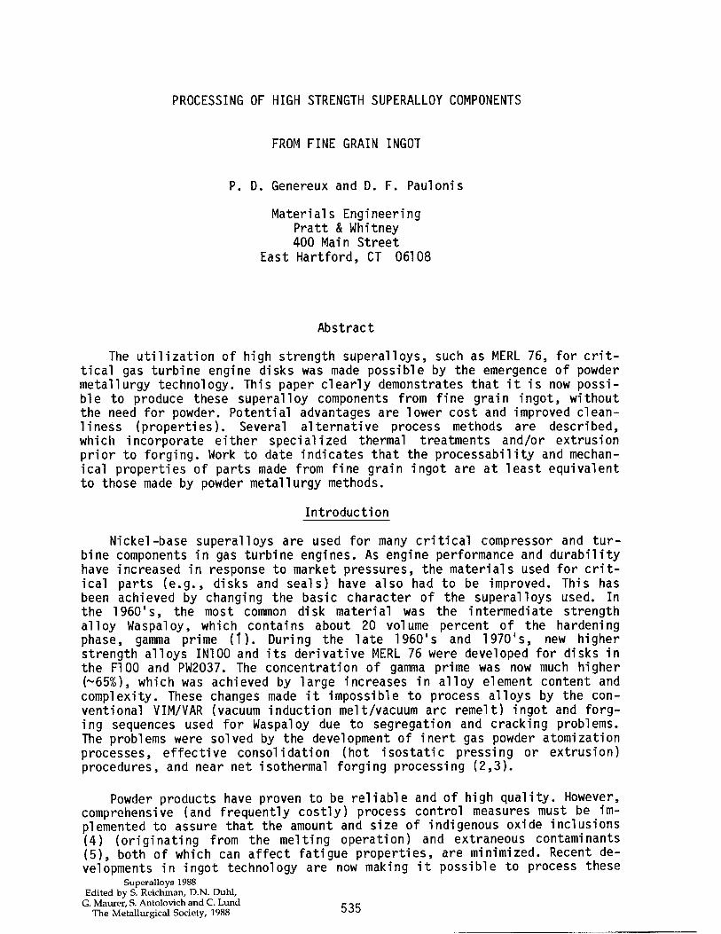
Most of the process development effort described in this paper used VADER material, which consists of electric arc remelting two horizontally opposing electrodes. The electrodes are fed toward each other while main- taining the desired gap and current density to produce low superheat drop- lets which are collected in a static or withdrawal mold (Figure 1). Various schemes are employed to distribute the molten metal and promote the desired steady-state melting and solidification mechanisms. If high purity material is required, the use of EBCHR (electron beam cold hearth refined) electrodes should be specified.
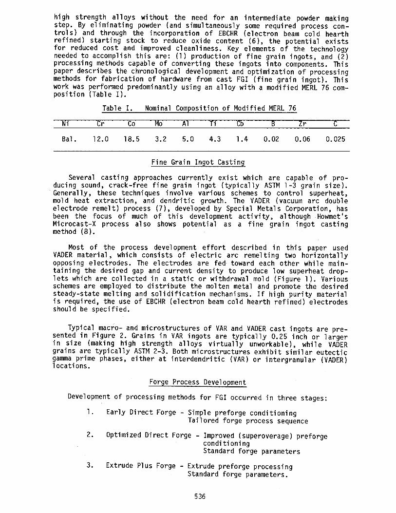
Typical macro- and microstructures of VAR and VADER cast ingots are pre- sented in Figure 2. Grains in VAR ingots are typically 0.25 inch or larger in size (making high strength alloys virtually unworkable), while VADER grains are typically ASTM 2-3. Both microstructures exhibit similar eutectic gamma prime phases, locations.
either at interdendritic (VAR) or intergranular (VADER)
Forge Process Development
Development of processing methods for FGI occurred in three stages:
1. Early Direct Forge - Simple preforge conditioning Tailored forge process sequence
2. Optimized Direct Forge - Improved (superoverage) preforge conditioning Standard forge parameters
3. Extrude Plus Forge - Extrude preforge processing Standard forge parameters.
536
st wh
STATIC
Figure 1 - Schematic illustrati VADER casting modes.
WITHDRAWAL
'ens of static and withdrawal
VAR VADER
Figure 2 - Macro (top) and micro VADER cast ingots.
(bottom) structures of VAR and
In most of the work described below, the fine grain ingots were hot is .atic pressed (HIP) below the gamma pri me solvus to close casting porosi ile maintaining the as-cast grain size .
537
Early Direct Forge Approach
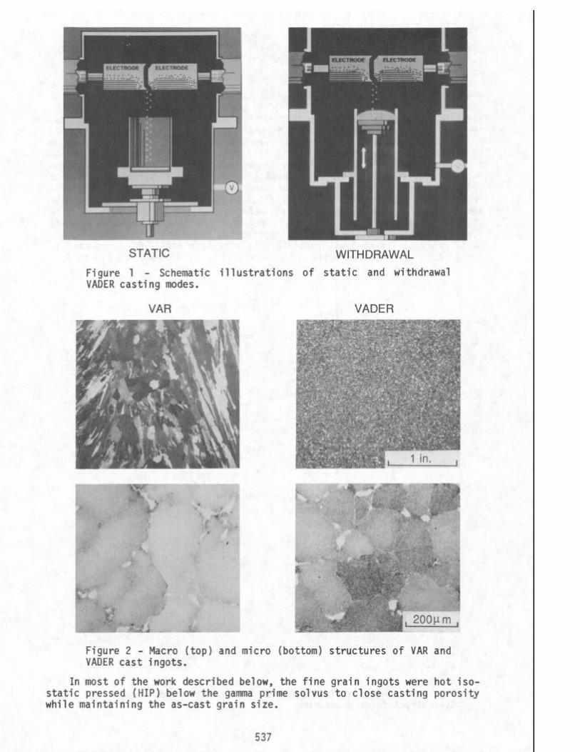
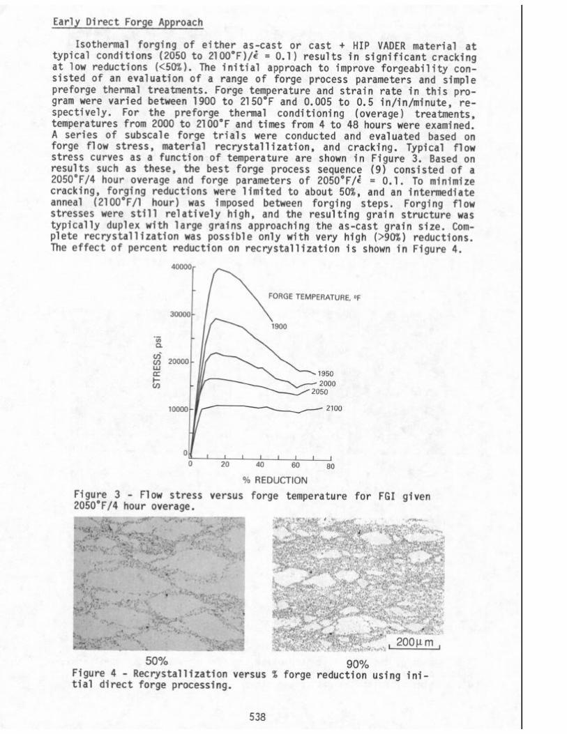
Isothermal forging of either as-cast or cast + HIP VADER material at typical conditions (2050 to 21OO"F)/t = 0.1) results in significant cracking at low reductions (<50%). The initial approach to improve forgeability con- sisted of an evaluation of a range of forge process parameters and simple preforge thermal treatments. Forge temperature and strain rate in this pro- gram were varied between 1900 to 2150°F and 0.005 to 0.5 in/in/minute, re- spectively. For the preforge thermal conditioning (overage) treatments, temperatures from 2000 to 2100°F and times from 4 to 48 hours were examined. A series of subscale forge trials were conducted and evaluated based on forge flow stress, material recrystallization, and cracking. Typical flow stress curves as a function of temperature are shown in Figure 3. Based on results such as these, the best forge process sequence (9) consisted of a 205O"F/4 hour overage and forge parameters of 205O"F/z = 0.1. To minimize cracking, forging reductions were limited to about 50%, and an intermediate anneal (21OO"F/l hour) was imposed between forging steps. Forging flow stresses were still relatively high, and the resulting grain structure was typically duplex with large grains approaching the as-cast grain size. Com- plete recrystallization was possible only with very high (>90%) reductions. The effect of percent reduction on recrystallization is shown in Figure 4.
I/ \ FORGE TEMPERATURE, OF
30000 \ 1900
.-
. I II-
i 2oooo[ /p&;;;i I'\
OK,,,,,,,, 20 40 60 80
% REDUCTION
Figure 3 - Flow stress versus forge temperature for FGI given 205O"F/4 hour overage.
{;f&f^> ” ‘Bc*;&B? s .*- .& - . ,; I P -'ye-
*.$+‘?b: ‘ e-a* _ ;+.ii” -.:- -‘, .~‘ ‘. ;w;cy .., ‘MC:; :"",r*$? ' .";Gv$&&~v; _,~i, , ;.~.~U.. _
'%, ; _ * ., ;... “‘-: . , &g$" ,-,z . s_l._ _ .‘i, “̂j ” -**xi. *:+d.-..~
s . d-i&: iA ~:.3.~~‘~$.?~ .‘* “<WC. <:- f ;“> ,Z”&, ̂---““,‘.‘;,> -‘.., .: ?-"i;w'"* y'~~~+~, _ ,) “et &f.-’ ‘tlllx(ri . . . . .r\-r”i-. _
-* ,I*: -* ,,I: ‘?;t’;.-;-&,, I d. .:.‘:“l::,r '?-tu.‘:v'B.#' 'I::, " ?pW “’ i .‘:,y(;;;, I ‘r:;‘. *’ ,y
c,* :&,+.*
.
phgs“' * e&&$y-~,,; i “( -ye. ,._ . ..,":,""," r-h:> E * I%.
. . . :" / .,,, ;* / ’ . ‘ * cr& \. I; .&?Y$
..?:.<‘a ; i . <.a . . L ,.,,, S” .a:--. I ~~‘::.““J,;,*” _, * * ‘- ‘. :*
: ,‘ *, ‘_ .;li. .&&:“,;g?;$ ,, ( yp; J : ‘,: . ** <* )‘“.’ 6 II ~.,-~~q?&T
(/.. ,,:.,: ‘, ‘--, “, ._,.. ,;i* ,;.:...+. <,a
I *sr- "ti" *\t. -*I ̂
-_.-- .I. ,, ,-I i I. b‘., :* _*. '**
b‘,y::,.l.y(,Ag I- : I c
** ,__ ‘. : ‘i ::\:.7s$q I c *; c .-,_ .*‘,<-” ~-;
;> \i ,‘.“;:,?.;;- -:‘Y::$ j M j *e* *". 7" *“.,,~,,: ;::p
,. , ("I._ . ,,a*s";.m , _ ,*a*
*,‘” *+;. .--,I * ,- *: I
-o,x-" .c
:-. .,.‘“e:. . ..*.” .; t( '."'*--"'*-. _." ,,.-* b&,‘““‘, :-. *i ".P ;-a,"" ,:.I
“,...” , .“;l$1~f, _: ~4 -‘:~,& . ‘4 ‘_ L ; 1 i ,$ . 5. L * _ , ;" I “z.* ,“:$ *,.,*,,, *
&.. a,* '6 i--r . . i ‘6‘. g-1. ::‘:,
,i i “)r, ,d ?
A p ‘e.,,, ‘.; v-. ,e. “p&7i c,~‘-3%i;~:;r:~;~~,\,, .-‘.Pi I ,,,e '-b? ‘ .
L,p%&$q&;.; ,~.s>.c:“#:. _ -)” ,t;5,gy?"~~~ rpcx"" . r >y~* &,< “ "L.."&c,&~f “i:*‘ ‘.‘; ^,_<( ; ,.,, C'.~r:.,*;.l.~L,.". ** I .'Y " ,I*,**; g--
.g..' : . #.T . &.*-.;-? . )( ,., _d
,
*.i~ , * -:*; ,, -,-* j,:.
-3,,fy-, 4 p, *
* * -, ys;:v,l:=_:,..ye 1 ‘1.: ,,,_ <‘#, ,&., 9 %-I>
1 I _ .*: . 9
.Y" : ‘ j- :-~..z.~,““‘~r ‘- .,_ ‘“--. ;,.,’ on’ ., -.:, ,/ *- I, :I “:i. :+- ".a. 1 “,JZ :
. z. , .-" ,,8;. ,*-I XI (P , ,;y... 1 *-- ,-.*'-
,$ .,,‘e,y,T I *" c. d t! g '>y;, ‘,-x’T;..,“hB~ ‘;:i”,;& ^_ ” L;:, ,:. ‘<,P” 7‘ . : ‘5, * *L, L; :. ,, **-* . 2
.~~~~~~~,~~~.~i~~:l:,~~~:-:II;;. ‘.s:*?* i"i‘c.,, r. _ / * s,,*.m $y;p >"a,', L1 .,1. & ‘.P;--“y ,,+““- :, . -. ~‘-I” ; * . b‘* *
pip "?';"" ‘ ,'- -- " _ *: -’ .:.“i’%qp; ;, ‘M.*‘ y,“*,;;,:‘I” ,,.
,) +~.-- ), ( y,,.;*.p ‘*‘-,j . ,*?;-x’ 7 ape.
.>+y ..; ';,@? '*' ' *'izyA-
y:r, g. p * ) ,1 /*., &<-’ . * WI. 1
- )' (, ‘. ,- ‘.+.,“<,.
._ *< :, i 1.2.. ,_
*<y&Y-* ,_ .” ,p” I,*. I.,
f e&t+& “r”, “,” i”*-: i;$j f .*" ', $"‘a& -9. ****' :.-:,.z~,;,~-.~. /,” h ze .'/" :. 3-r _
.:” ~~~~l,;;‘i:,‘~.~;*.~~~~~~~~~~;~~; .,.~~~~~~~~~.~~~~~*.“,~~~~~i, :, : ‘~~~~~~~~i:~~~~~~~~~~~i.li, :~~~~~-~~~~.~~~,.;~.s:-~ I,@
,$’ -’ . ,,y:,:,:. ,, ‘5’ ji~...,,.,t.:?:‘::~~ I’- ,~:z*~>“‘ J,.-+ I.*j ,,J
* “‘ I I.' 3 _ I . i *.*( q-..; *;i,. $
~. -..* r:' *; .- " .** I I.., 5 , ", : ;*g+ ".T. .,f. *,,* 8' ., , .) .,,, \ "*:* ai‘< ' , ..>,'\ i *ai‘< ' 200um, 200um,
50% 90% Figure 4 - tial
Recrystallization versus % forge reduction using ini- direct forge processing.
538
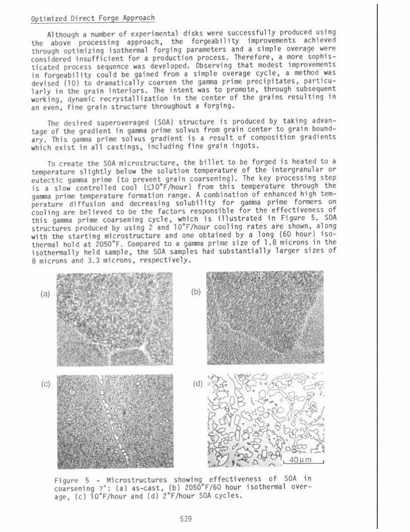
Optimized Direct Forge Approach
Although a number of experimental disks were successfully produced using the above processing approach, the forgeability improvements achieved through optimizing isothermal forging parameters and a simple overage were considered insufficient for a production process. Therefore, a more sophls- ticated process sequence was developed. Observing that modest improvements in forgeability could be gained from a simple overage cycle, a method was devised (10) to dramatically coarsen the gamma prime precipitates, particu- larly in the grain interiors. The intent was to promote, through subsequent working, dynamic recrystallization in the center of the grains resulting in an even, fine grain structure throughout a forging.
The desired superoveraged (SOA) structure is produced by taking advan- tage of the gradient in gamma prime solvus from grain center to grain bound- ary. This gamma prime solvus gradient is a result of composition gradients which exist in all castings, including fine grain ingots.
To create the SOA microstructure, the billet to be forged is heated to a temperature slightly below the solution temperature of the intergranular or eutectic gamma prime (to prevent grain coarsening). The key processing step is a slow controlled cool (IIO"F/hour) from this temperature through the gamma prime temperature formation range. A combination of enhanced high tem- perature diffusion and decreasing solubility for gamma prime farmers on cooling are believed to be the factors responsible for the effectiveness of this gamma prime coarsening cycle, which is illustrated in Figure 5. SOA structures produced by using 2 and lO"F/hour cooling rates are shown, along with the starting microstructure and one obtained by a long (60 hour) iso- thermal hold at 2050°F. Compared to a gamma prime size of 1.8 microns in the isothermally held sample, the SOA samples had substantially larger sizes of 8 microns and 3.3 microns, respectively.
UN
Figure 5 - Microstructures showing effectiveness of SOA in coarsening 7': (a) as-cast, (b) 205O"F/60 hour isothermal over- age, (c) lO"F/hour and (d) Z"F/hour SOA cycles.
539

Limited forge parameter studies demonstrated that conventional iso- thermal forge parameters of 205O"F/i = 0.1 worked well for material given the SOA treatment. This treatment had the desired effect of resulting in a completely recrystallized structure (ASTM 7-8) at forging reductions as low as 50% (Figure 6a). Furthermore, forging flow stresses were approximately half of those experienced with the earlier direct forge process and de- creased (as expected) with decreasing SOA cooling rate (Figure 7). For best results, an SOA cooling rate of LS"F/hour is preferred.
Figure 6 - Recrystallized microstructures of forgings made using the direct forge (a) and extrude plus forge (b) processes following an SOA treatment.
7.6 -
7.2 -
6.4 - 0
60.1 I I I I I 11 1 I 0 2 4 6 8 10
COOLING RATE (OF/hour)
Figure 7 - Effect of SOA cooling rate on forging flow stress.
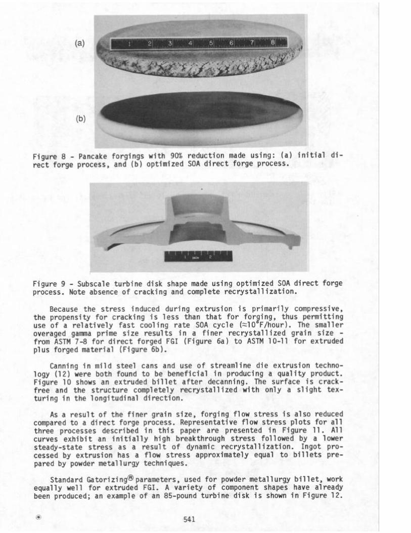
Forge cracking, and hence the need for multiple forge steps, was vir- tually eliminated with this process. Numerous pancake forgings were produced with reductions in excess of 90% with no sign of cracking or checking on the rim. An example is shown in Figure 8, next to another pancake forged to sim- ilar reduction using the earlier direct forge process which shows severe cracking. Complex closed die forgings were produced equally successful. As shown in Figure 9, a subscale turbine disk shape was crack-free and com- pletely recrystallized (full diametral cross section is macroetched).
Extrude Plus Forge Approach
Addition of an extrusion step prior to isothermal forging provides even further advantages in the processing of FGI (11). Unlike forging, extrusion of fine grain ingots directly in the as-cast or HIP condition is possible, though not without some difficulty. However, an SOA preconditioning thermal treatment was found to reduce cracking and promote recrystallization, espe- cially at low extrusion ratios.
540
--’ \’ \ ,\, /
Figure 8 - Pancake forgings with 90% reduction made using: (a) initial di- rect forge process, and (b) optimized SOA direct forge process.
Figure 9 - Subscale turbine disk shape made using optimized SOA direct forge process. Note absence of cracking and complete recrystallization.
Because the stress induced during extrusion is primarily compressive, the propensity for cracking is less than that for forging, thus permitting use of a relatively fast cooling rate SOA cycle (=lO"F/hour). The smaller overaged gamma prime size results in a finer recrystallized grain size - from ASTM 7-8 for direct forged FGI (Figure 6a) to ASTM lo-11 for extruded plus forged material (Figure 6b).
Canning in mild steel cans and use of streamline die extrusion techno- logy (12) were both found to be beneficial in producing a quality product. Figure 10 shows an extruded billet after decanning. The surface is crack- free and the structure completely recrystallized with only a slight tex- turing in the longitudinal direction.
As a result of the finer grain size, forging flow stress is also reduced compared to a direct forge process. Representative flow stress plots for all three processes described in this paper are presented in Figure 11. All curves exhibit an initially high breakthrough stress followed by a lower steady-state stress as a result of dynamic recrystallization. Ingot pro- cessed by extrusion has a flow stress approximately equal to billets pre- pared by powder metallurgy techniques.
Standard Gatorizing@parameters, used for powder metallurgy billet, work equally well for extruded FGI. A variety of component shapes have already been produced; an example of an 85-pound turbine disk is shown in Figure 12.
0 541

I 1 FT. I
EXTRUDED LOG
ENLARGEMENTSHOWING SURFACE QUALITY
CROSSSECTION SHOWING MACROSTRUCTURE
Figure 10 - structure.
As-extruded FGI showing detail of surface quality and macro-
0 I t 0 f I 1
0.2 I I
0.4 1
0.6 0.8
STRAIN (in/in)
Figure 11 _ Forging flow stress plots for all three FGI processing methods.
Figure 12 - Extruded and forged FGI 85-pound turbine disk.
542

Mechanical property evaluation has been initiated on the FGI product. Results to date have shown tensile and stress-rupture properties to be well above goal values (Figure 13). Notched rupture lives, in particular, are typically an order of magnitude better than an equivalent powder product. Other properties (low cycle fatigue, crack growth) have shown equivalence to a powder product.
140- - Y.S. GOAL’
120-
SMOOTH
NOTCHED
GOAL
1 I I I I t 200 400 600 800 1000 1200 1400 10 100 1000
TEMPERATURE (OF) LOG LIFE (hours)
(a) TENSILE (b) STRESS RUPTURE (1350°F/95 ksi)
Figure 13 - Tensile and stress rupture properties of direct forge and extrude + forge FGI modified MERL 76.
Conclusions
The work described in this paper clearly demonstrates the feasibility of producing complex parts from high strength superalloy fine grain ingots. Production incorporation, however, will ultimately depend on a variety of factors such as: process economics, capital equipment availability, and additional property testing to verify that high property levels can be con- sistently achieved.
Acknowledgements
The authors gratefully acknowledge A. J. Nytch for his skilled technical assistance; E. E. Brown and D. R. Malley for their individual contributions to this technology; and M. J. support.
Blackburn for his guidance and continuing
References
1. M. J. Donachie, Jr., "Introduction to Superalloys," Superalloys Source Book, 1984, 3-16.
2. J. B. Moore and R. L. Athey, "Fabrication Method for the High Tempera- ture Alloys," U.S. Patent No. 3,519,503, July 7, 1970.
3. G. H. Gessinger, "Recent Development in Powder Metallurgy of Super- alloys," Powder Metallurgy International, 13119811, 93-101.
543
4.
5.
6.
7.
8.
9.
E. E. Brown et al., "The Influence of VIM Crucible Composition, Vacuum Arc Remelting and Electroslag Remelting of the Non-Metallic Inclusion Content of MERL 76, Superalloys 1980, 159-168.
D. R. Chang, D. D. Krueger and R. A. Sprague, "Superalloy Powder Pro- cessing, Properties and Turbine Disk Applications," Superalloys 1984, 245-273.
E. E. Brown and R. W. Hatala, "Electron Beam Refining of Nickel-Base Superalloys," Electron Beam Melting - State of the Art 1985, Part II, 103-117.
W. J. Boesch, G. E. Maurer and C. B. Adasczik, "VADER - A New Melting and Casting Technology," High Temperature Alloys for Gas Turbines, 1982, 823-838.
J. R. Brinegar, L. F. Norris and L. Rozenberg, "Microcast-X Fine Grain Casting - A Progress Report," Superalloys 1984, 23-32.
D. F. Paulonis, D. R. Malley and E. E. Brown, "Forging Process for Su- peralloys," U.S. Patent No. 4,579,602, April 1, 1986.
10. P. D. Genereux and D. F. Paulonis, "Nickel-Base Superalloy Articles and Method for Making," U.S. Patent No. 4,574,105, March 4, 1986.
11. U.S. Patent Pending.
12. H. L. Gegel et al., "Computer Aided Design of Extrusion Dies by Metal Flow Simulation," AGARD-LS-137, 8-1, 1984.
544