Processing and Characterization of Titanium-Hydroxyapatite...
46
Processing and Characterization of Titanium-Hydroxyapatite Metal Matrix Composite for Biomedical Applications A THESIS SUBMITTED IN PARTIAL FULFILLMENT OF THE REQUIREMENT FOR THE DEGREE OF Bachelor of Technology in Biotechnology by Shammy Raj 109BT0683 Under the Supervision of Dr. A. Thirugnanam Department of Biotechnology and Medical Engineering National Institute of Technology Rourkela Rourkela, Odisha, 769 008, India May 2013
Transcript of Processing and Characterization of Titanium-Hydroxyapatite...
Processing and Characterization of Titanium-Hydroxyapatite
Metal Matrix Composite for Biomedical Applications
A THESIS SUBMITTED IN PARTIAL FULFILLMENT
OF THE REQUIREMENT FOR THE DEGREE OF
Bachelor of Technology
in
Biotechnology
by
Shammy Raj
109BT0683
Under the Supervision of
Dr. A. Thirugnanam
Department of Biotechnology and Medical Engineering
National Institute of Technology Rourkela
Rourkela, Odisha, 769 008, India
May 2013

Department of Biotechnology and Medical Engineering
National Institute of Technology Rourkela
Rourkela - 769008, Odisha, India.
Certificate
This is to certify that the thesis entitled “Processing and Characterization of Titanium-
Hydroxyapatite Metal Matrix Composite for Biomedical Applications” by Shammy Raj
(109BT0683), in partial fulfillment of the requirements for the award of the degree of Bachelor
of Technology in Biotechnology during session 2009-2013 in the Department of Biotechnology
and Medical Engineering, National Institute of Technology Rourkela, is an authentic work
carried out by him under my supervision and guidance. To the best of my knowledge, the matter
embodied in the thesis has not been submitted to any other University/Institute for the award of
any degree or diploma.
Place: NIT Rourkela Dr. A. Thirugnanam
Date: 12th
May 2013 Assistant Professor
Biotechnology and Medical Engineering
National Institute of Technology
Rourkela-769 008, Odisha (India)
(i)

Acknowledgement
Successful completion of this project is the outcome of consistent guidance and assistance from
many people, faculty and friends and I am extremely fortunate to have got these all along the
completion of the project.
I owe my profound gratitude and respect to my project guide, Prof. A. Thirugnanam,
Department of Biotechnology and Medical Engineering, NIT Rourkela for his invaluable
academic support and professional guidance, regular encouragement and motivation at various
stages of this project.
I also thank Dr. Ashok Kumar Mondal, Asst. professor, Department of Metallurgical and
Materials engineering, NIT Rourkela. I am extremely grateful to him for his consistent guidance
and support.
I place on record my sincere gratitude to Prof. Krishna Pramanik, Head of Department,
Department of Biotechnology and Medical Engineering, NIT Rourkela for her constant
encouragement.
I would like to thank Ms. Tejinder Kaur and Mr. Deependra Kumar Ban, Ph.D Scholar
Department of Biotechnology and Medical Engineering, NIT Rourkela and Mr. Anil Kumar
Singh Bankoti, Ph.D scholar, Department of Metallurgical and Materials engineering, NIT
Rourkela for their regular support, help and motivation.
I would also thank my Institution and my faculty members without whom this project would
have been a distant reality. I also extend my thanks to my family, friends, and well-wishers.
(ii)

Finally I would like to express my heartiest thank to my friend Prasanna Chandra Jha for his
constant help and encouragement during the project. I thank him for being with me throughout
the completion of project.
Place: NIT Rourkela Shammy Raj
Date: 12th
May 2013 109BT0683
Biotechnology and Medical Engineering
National Institute of Technology
Rourkela-769 008, Odisha (India)
(iii)
Contents
Page No.
Certificate (i)
Acknowledgement (ii)
Abbreviations (vi)
List of Tables (vii)
List of Figures (viii)
Abstract (ix)
Chapter 1 – Introduction 1
1.0. Introduction 2
1.1.Conventional Biomaterials 3
1.1.1. Stainless Steel 3
1.1.2. Cobalt – Chromium alloys 3
1.1.3. Magnesium and its alloys 4
1.1.4. Titanium and its alloys 4
1.1.5. Shape memory alloys 5
1.1.6. Titanium – Hydroxyapatite composite 5
Chapter 2 – Literature Review 6
2.1 International status 7
2.2 National status 10
Chapter 3 – Materials and method 11
3.1 Sample preparation 12
3.2 Sample characterization 12
3.3 Density measurement 13
3.4 In-vitro bioactivity study in SBF 13
(iv)

Chapter 4 – Result 15
4.1 Density measurement 16
4.2 XRD analysis 16
4.2.1 Powder composite characterization 16
4.2.2 Sintered composite characterization 17
4.2.3 In-vitro bioactivity study in SBF 19
4.3 SEM characterization 21
4.3.1 Powder composite 21
4.3.2 Sintered composite 22
4.3.3 In-vitro bioactivity study in SBF 22
Chapter 5 – Discussion 26
5.1 Powder composite 27
5.2 Sintered composite 27
5.3 In-vitro bioactivity study in SBF 28
Chapter 6 – Conclusion 30
References 32
(v)

Abbreviations
1. Ti – Titanium
2. Cp Ti – Commercially pure Titanium
3. Ha – Hydroxyapatite
4. Ti-Ha – Titanium Hydroxyapatite
5. Ti10 – Titanium Hydroxyapatite with 10 weight% of Hydroxyapatite
6. Ti15 – Titanium Hydroxyapatite with 15 weight% of hydroxyapatite
7. SBF – Simulated body fluid
8. SEM – Scanning electron microscopy
9. XRD – X-ray diffraction
10. Rpm – Revolutions per minute
11. g – gram
12. ml – milli liter
13. mm – milli meter
14. cc – centimeter cube
15. wt. – weight
16. h – hours
17. min – minutes
(vi)
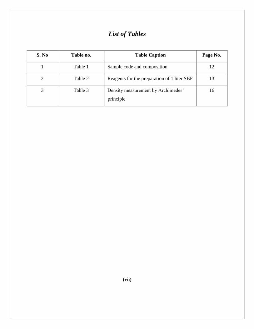
List of Tables
S. No Table no. Table Caption Page No.
1 Table 1 Sample code and composition 12
2 Table 2 Reagents for the preparation of 1 liter SBF 13
3 Table 3 Density measurement by Archimedes’
principle
16
(vii)

List of Figures
S. No. Figure No. Figure Caption Page No.
1 Fig. 1 XRD pattern of ball milled pure Cp-Ti powder for
various time intervals.
18
2 Fig. 2 XRD pattern of ball milled Ti10 powder for various
time intervals.
18
3 Fig. 3 XRD pattern of ball milled Ti15 powder for various
time intervals.
18
4 Fig. 4 XRD pattern of compacted and sintered samples. 18
5 Fig. 5 XRD pattern of sintered pure Cp-Ti soaked in SBF for
1 and 2 weeks.
20
6 Fig. 6 XRD pattern of sintered Ti10 composite soaked in SBF
for 1 and 2 weeks.
20
7 Fig. 7 XRD pattern of sintered Ti15 composite soaked in SBF
for 1 and 2 weeks.
21
8 Fig. 8 SEM micrograph of 8 h ball milled composite powder. 23
9 Fig. 9 SEM micrograph of polished and sintered composite. 24
10 Fig. 10 SEM micrograph of ball milled and sintered samples
soaked in SBF.
25
(viii)
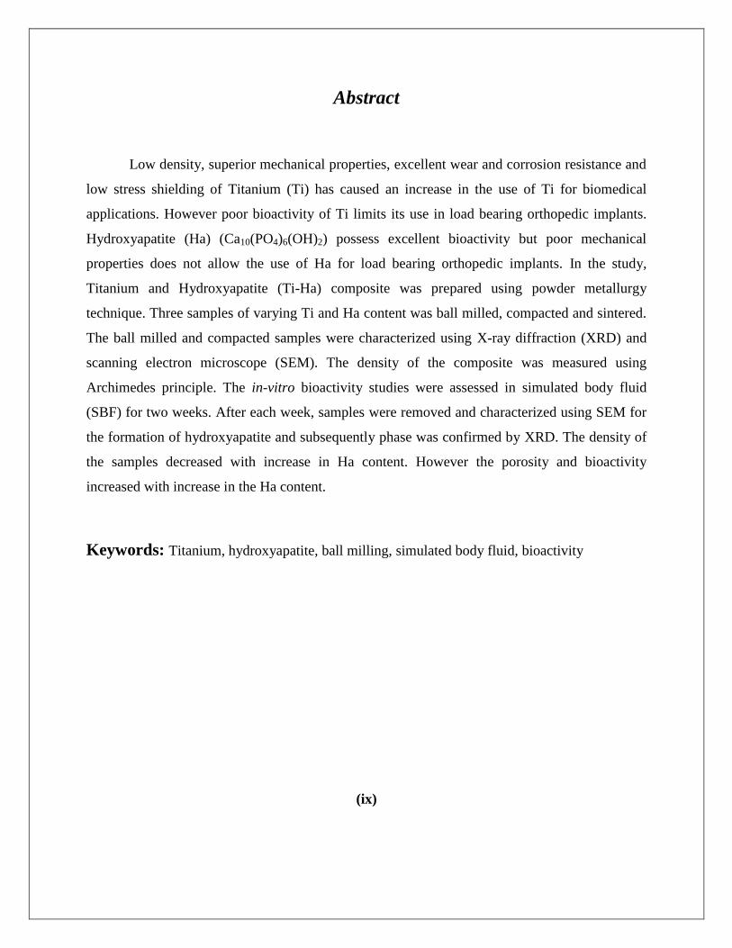
Abstract
Low density, superior mechanical properties, excellent wear and corrosion resistance and
low stress shielding of Titanium (Ti) has caused an increase in the use of Ti for biomedical
applications. However poor bioactivity of Ti limits its use in load bearing orthopedic implants.
Hydroxyapatite (Ha) (Ca10(PO4)6(OH)2) possess excellent bioactivity but poor mechanical
properties does not allow the use of Ha for load bearing orthopedic implants. In the study,
Titanium and Hydroxyapatite (Ti-Ha) composite was prepared using powder metallurgy
technique. Three samples of varying Ti and Ha content was ball milled, compacted and sintered.
The ball milled and compacted samples were characterized using X-ray diffraction (XRD) and
scanning electron microscope (SEM). The density of the composite was measured using
Archimedes principle. The in-vitro bioactivity studies were assessed in simulated body fluid
(SBF) for two weeks. After each week, samples were removed and characterized using SEM for
the formation of hydroxyapatite and subsequently phase was confirmed by XRD. The density of
the samples decreased with increase in Ha content. However the porosity and bioactivity
increased with increase in the Ha content.
Keywords: Titanium, hydroxyapatite, ball milling, simulated body fluid, bioactivity
(ix)
1
Chapter 1: Introduction

2
1.0. Introduction
Aging and accidents are two important causes which lead to injury, damage and
disease in the bone tissue. Though bone tissue has a property of regenerative growth and
remodeling, it fails in some critical accidents and diseases. One effective approach to
solve this problem is grafting. Autografts, allografts and syngrafts are the main
approaches to replace lost bones or repairing bone defects. Autografting has good
compatibility and it triggers no immunological response; however the limited donor bone
supply and the additional trauma involved has limited its application.
Many artificial bone tissues of ceramics and metals are being developed to facilitate bone
regenerative growth and bone healing. Biomaterials are natural or synthetic materials
engineered to function similar to that of damaged tissue in bio-environment. A material to
be used as a biomaterial should have an excellent biocompatibility and bioactivity.
Beside these it should also have mechanical properties similar to that of the damaged or
diseased bone. High corrosion and wear resistance also plays an important role for
biomaterials used in load bearing sites. [1]
Metallic biomaterials are preferred in load bearing orthopedic implants due to good
mechanical properties. Metals and alloys that combine high strength with reasonable
corrosion resistance are favorite biomaterials for the fabrication of orthopedic implants
which are subjected to severe mechanical loading inside the human body. Metallic
biomaterials have greatly attracted the researchers and further research is necessary to
improve the properties like tensile strength, Youngs’ modulus, fatigue fracture, stress
shielding, wear and corrosion resistivity, biocompatibility and bioactivity. The materials
currently used for surgical implants include calcium phosphate ceramic, 316L stainless
steel (316LSS), cobalt chromium (Co–Cr) alloys, magnesium and its alloys and titanium
and its alloys [1-2]. Recent advancement in the field of biomaterials has seen the
development of titanium-hydroxyapatite (Ti-Ha) composite which possess the blend of
excellent mechanical properties of titanium and better bioactivity of hydroxyapatite [3-5].

3
1.1 Conventional Biomaterials
1.1.1 Stainless steel: The metallic biomaterial most commonly used for orthopedic
applications earlier was the austenitic stainless steel. Its utilization is particularly
justified by the combination of properties such as good acceptance by the body; low cost;
good machinability; good formability; high strength, especially when cold worked and
reasonable corrosion resistance. However, some aspects such as low strength in the
annealed condition and susceptibility to localized corrosion often limits the wider use of
this type of material in orthopedic applications, mainly when the implanted device must
remain in the human body for a relatively long time (more than 12 months). The
combination of such aspects favors the failure of orthopedic implants by a synergy called
as corrosion–fatigue [6]. Ni and Cr are main components of stainless steel. These
implants are reported to release these elements due to corrosion in the body. Ni and Cr
released from prosthetic implants have been reported to be toxic. Skin related diseases
such as dermatitis due to Ni toxicity have also been reported [1]. In addition, 316L SS
possess much higher modulus than bone, leading to insufficient stress transfer to bone
leading to bone resorption and loosening of implant after some years of implantation. The
high cycle fatigue failure of hip implants is also reported as the implants are subjected to
cycles of loading and unloading over many years [1].
1.1.2 Cobalt chromium alloys: Co–Cr based alloys are the most commonly used
representative of Co alloys for biomedical applications. The presence of Cr imparts the
corrosion resistance and the addition of small amounts of other elements such as iron,
molybdenum or tungsten can give very good high temperature properties and abrasion
resistance. The various types of Co – Cr alloys used for implant applications include Co–
Cr–Mo, Co–Cr–Mo, Co–Cr–W–Ni and Co–Ni–Cr–Mo–Ti. Clinical applications of such
alloys include its use in dentistry and maxillofacial surgery. However high cost, low
formability and poor machinability are some of the limitations, preventing the use of
these metallic materials for orthopedic applications. Also like stainless steel, Co and Cr
are toxic and causes skin disease. Co has also been reported to be carcinogenic [1].

4
1.1.3 Magnesium and its alloys: As an important essential trace element, magnesium
participates in almost all the human metabolism, ranking just after calcium, sodium and
potassium. Its density (1.74g/cm3) is close to that of natural bone (1.75g/cm
3).
Meanwhile, its high specific strength (pure Mg, 133 GPa/ (g·cm3)) and specific stiffness,
can meet the strength performance requirements of biological implant materials. As a
biodegradable implant material, magnesium provides both biocompatibility and sufficient
mechanical properties. Mg alloys are very attractive due to their good biocompatibility
and especially their degradability. Researchers found that magnesium alloys offer great
potential as absorbable implant materials such as cardiovascular tube stent and bone
fixation materials for instance as bone screws or plates. Within a certain time span after
surgery, they degrade and are completely suitable to medical functions [1-2, 7-8].
However, several problems need to be settled for the application of Mg to the biomedical
field, such as poor corrosion resistance in chloride containing solutions and pittings
especially in body fluid condition.
1.1.4 Titanium (Ti) and its alloys: Ti and its alloys possess low modulus varying from 110
to 55 GPa [1]. Commercially pure Ti and Ti–6Al–4V are most commonly used titanium
materials for implant applications. High corrosion resistance and excellent biocompatibility
increases its suitability for biomedical industry. The mechanical strength of the Ti and its
alloys is very close to that of 316 L SS, and its density is 55% less than steel. The
applications cover joint replacement parts for hip, dental implants, knee, elbow, spine,
shoulder etc. Although titanium and its alloys mainly Ti6Al4V have an excellent corrosion
resistance and biocompatibility, long term use leads to release of Al and V ions. Both
vanadium and aluminum ions released from the Ti6Al4V alloy are found to be cause long-
term health problems, like Alzheimer disease etc [1]. Toxicity of vanadium has also been
reported, both in the elemental state and oxides V2O5, which are present at the surface.
Bioinertness of Ti also restricts its use [1].
Beside Cp-Ti and Ti6Al4V, β-titanium alloys such as Ti-Ta alloys; Ti-Mo alloys; Ti-Nb
and Ti-Ni shape memory alloys are very much attracted as bioimplants [1, 9]. These
alloys exhibit high corrosion resistance and biocompatibility. Ti-Ta alloys have much

5
lower modulus and a good combination of high strength and low modulus. They have the
great potential to become new candidates for biomedical applications. Adding Zr to the
Ti alloy lowers the Young’s modulus and other mechanical properties suitable for
biomedical applications [1].
1.1.5 Shape memory alloys: Nickel-titanium (Ni-Ti) shape memory alloys have been
recently discovered as a very important bone implant due to its excellent mechanical
properties, good corrosion resistance, high biocompatibility, special pseudoelasticity and
shape as well as volume memory effect. Its porous structure permits the ingrowth of new-
bone tissue along with the transport of body fluids. Moreover, by obtaining different
porosity through controlling the processing parameters, the elastic modulus of the final
porous Ni–Ti could be adjusted and matched with that of human bone [9]
1.1.6 Ti-Ha metal matrix composite: Recent advancement in this field of biomaterials
which has caught the eye of researcher’s is Ti-Ha metal matrix composite. The excellent
biocompatibility and bioactivity of Ha is blended with the inert and superior mechanical
properties of titanium to get a composite with enhanced biocompatibility, bioactivity and
favorable mechanical properties [4, 10-11]. This composite has been reported to be non-
toxic and highly bioactive. The porous nature facilitates the bone in growth and better
osseointegration. The in vitro results in simulated body fluid (SBF) have shown dense
hydroxyapatite particles deposited on the implant [3-5]. Also it has been found that
tensile strength, Young’s modulus decreases with increase in volume fraction of Ha. This
composite has also been found to be thermodynamically and electrochemically stable in the
body environment [12].
The present research work deals with deals with the processing of Ti-Ha composite and its
characterization as biomaterial. The composite is prepared by powder metallurgy technique. The
composite powder is then compacted, sintered and its bioactivity is assessed in SBF.
6
Chapter 2: Literature Review

7
2.1 International Status: A lot of work has been done internationally in this field. Few noted
works related to this project are listed below.
Wen Shi et. al, 2002, varied the volume of Ha from 3% wt. to 30% wt. and reported that Ha
distribution up to 15% wt. of Ha had no defect. Non-uniformity appeared from above 22%
wt. The tensile strength for 22% wt. was reported to be 140 Mpa and decreased as Ha
content increased. Crystalline apatite was formed when samples were soaked in SBF for 14
days [13]
C. Q. Ning et. al, 2004; studied the processing of bioactive material using Ti, Ha and
bioglass. The bioglass was kept fixed at 10% by volume while Ha was varied from 20 to 60%
by volume. It was reported that the optimum temperature for sintering the Ti-Ha composite
was 1200o
C and Ha did not decompose at this temperature. Ti at 1200o
C remained in its
h.c.p. structure (α-Ti) [14].
Congqin Ning et. al, 2008; prepared Ti-Ha composite by ball milling and sintering. The
polished samples were immersed in SBF as well as transplanted in to a rabbit. Apatite
particles were formed on the sample with higher Ti content. However the gap in bone
formation was observed with increasing Ti. A thin film of bone had developed after one
month in the pores of the sample. The thickness of the bone increased after 6 months.
However no bonding at the interface was reported [3].
G. Zhao et. al, 2012; studied plasma sprayed Ti-Ha biocomposite. Ha content was varied
from 80% wt. to 20% wt. It was found that ball milled powders consisted of spherical Ti-Ha
composite particles. Microhardness, modulus of elasticity and bond strength increased with
increasing Ti. The elasticity of composite containing 80% wt. Ha was 52.1 GPa. Also the
composite showed apatite formation except for the composite containing 20% wt. Ha [15].
Chu Chenglin et. al, 1999; processed a functionally graded Ti-Ha composite. Decline in
density with increase in Ha concentration was reported. The relative density was found to be

8
maximum in the two pure component regions. Hardness increased up to the region with 20%
volume Ha. However the hardness decreased in the 40% volume Ha region to 80% volume
Ha region due to decrease in density. Young’s modulus was also observed to decrease in the
40 – 80% volume Ha regions [16].
S. Salman et. al, 2009; reported that high densification regime was observed after sintering
the Ti-Ha composite at 1300o
C whereas sample sintered at 10000 C showed poor
densification when characterized [17].
C.Q Ning et. al, 2002; studied the milling of Ti and Ha powders in 1:1 ratio and sintering at
1200o C. Many globular apatite particles had formed on the pores of the sample on immersion
of the sample in SBF during bioactivity test. The pH increased gradually throughout the
immersion process [3]
Shahrjerdi et. al, 2011; prepared Ti-Ha composite by powder metallurgy with varying Ti, Ha
content . It was observed that hardness increased with increase in Ha but for 25 - 70% wt. Ha
compositions, lower density resulted in the decrease of hardness. [10]
Q.Chang et. al, 2011, synthesized Ti-Ha composite by powder metallurgy. It was reported
that Ha was thermally stable at 1000o
C and no decomposition of Ha occurred. It was also
found that after immersion in SBF for 1 week, tiny apatite particles were formed on the
surface of the samples. A dramatic increase in the precipitate was observed after 5 weeks [5].
Jung G Lee et. al; 2010; studied the effect of milling on the Ti-Ha composite. TiO2 containing
both rutile and anatase phase was mixed with Ha. Ball milling speed and the ball milling time
was varied. It was found that on increasing the ball milling time, anatase phase transformed to
rutile phase. It was also found that phase transformation increased with decrease in Ha
content [11].
A Siddhartan et. al, 2010; used microwave to sinter the titania-hydroxyapatite composite. A
layer of Ha coating was observed on the Ti-Ha composite surface without any delamination.

9
However oxide had formed on the surface. In the bioactivity test it was found that Ha
particles had formed on the grain boundaries of oxide and over the Ha particles. The samples
also showed better cell adhesion and cell spreading [18].
Q Chang et. al, 2010; blended Ti, Fe and Ha. The samples were ball milled and sintered at
1000o
C. It was observed that on adding Ti-Fe the average density of the composite decreases.
The hardness also decreases with increase in Ti-Fe concentration. It was further concluded
that the presence of Fe reduces the decomposition of Ha [19].
Anawati et. al, 2013; reported that the corrosion potential of Ti-Ha composite increased and
stabilized the surface leading to passivation. This showed high corrosion resistance of the Ti-
Ha composite. SBF test showed globular particles after 2 day immersion in SBF. Pure Ti
sample did not show any apatite on its surface on immersion in SBF [12].
Wenxiu Que et. al, 2008; prepared a biocomposite by mixing the TiO2 and Ha particles. The
mixed powders were ball milled and spark plasma sintered. It was reported that hardness and
modulus of the composite are functions of sintering temperature. Both modulus and hardness
increases with increase in sintering temperature. Nano sized flaky crystallite of apatite had
formed on nano-composite compact [20].
X. Zhou et. al, 2012; prepared Ti composite from Ti powders and Ha was cold sprayed over it.
It was reported that 20% wt. Ha-Ti composite coating shows more corrosion current and thus
poor corrosion resistance [21].
Xuebin Zheng et. al, 2000; processed Ti-Ha composite by ball milling. Ti6Al4V was used as
substrate for plasma spraying. Polished specimens were soaked in SBF. It was reported that
the bond strength of the coating increases on adding Ti to Ha. Adhesion increased on further
increasing the Ti content. The cohesive strength of the particles in the coating also increases
on increasing the Ti content. Apatite coating was observed even after I day of coating [22].

10
Chenglin Chu et. al, 2006; prepared functionally graded Ti-Ha composite by powder
metallurgy technique. It was observed that new bone had developed after 8 weeks of
implantation. Bone tissues were formed after 28 months. It was concluded that
osseointegration and osseoinduction of functionally graded composite is more than that of
pure Ti, and that the bonding strength increases slowly after different implanting time while
that of functionally graded material increases at much faster rates [23].
2.2 National status: Very few researchers have worked in this field. However detailed and
systematic study in this area is required.
11
Chapter 3: Materials and Methods

12
Pure Cp-Titanium powder (supplied by Himedia) was mixed with pure Ha powder. The powders
were mixed in varying % wt. ratio and coded as shown in Table 1.
Table 1: Sample code and composition
Sample code Titanium (Ti) (% wt.) Hydroxyapatite (Ha) (% wt.)
Ti 100 0
Ti10 90 10
Ti15 85 15
3.1 Sample preparation
The Ti and Ha powders were mixed according to their respective % wt. as shown in
Table 1 and then ball milled in a planetary ball mill machine (Fritsch Planetary Ball Mill
– Puluerisette 5) for 8 h. Ethanol was used as wetting media. Ball milling was done using
stainless steel vial and stainless steel balls and the ball to powder mass ratio 20:1 was
maintained. The ball milling was done at 300 rpm and milling was done in a cycle of 15
min and was put on rest for next 15 min. This cycle was continued till 8 h of effective
milling time. The milled powders were compacted in uniaxial single action (SOILLAB,
Delhi) hydraulic compaction machine, using a 15 mm diameter die and using 10 ton load.
Zinc stearate was used as lubricant. The green compact was then sintered in muffle
furnace (SEMAG Industries) at 900oC for 30 min in normal atmosphere. The heating rate
was set as 200oC/min.
3.2 Sample characterization
The sintered samples were polished on grade 1 to 4 abrasive silicon carbide paper.
Polished samples were cleaned in distilled water and ultrasonicated in acetone for 15 min.
The as milled and sintered samples were characterized using scanning electron
microscope (SEM), (JEOL JSM – 6480LV) and XRD (PANalytical - Xpert 3040Y00) for
morphology and phase contamination. The scanning range for XRD was between 20o
-
60o with a step size of 3
o/min.

13
3.3 Density measurement
The polished and ultrasonicated samples were immersed in a measuring cylinder
containing distilled water. The corresponding change in the volume of the water was
measured. The densities of the samples were calculated using Archimedes’ principle.
According to the Archimedes principle, the increase in volume of water corresponded to
the volume of the immersed sample. The density of the samples was calculated from the
fundamental formula, density = mass/volume.
3.4 In-vitro bioactivity study in SBF
The polished samples were ultrasonically cleaned in distilled water and then acetone
for 15 min and dried. The samples were soaked in freshly prepared SBF for 2 weeks. The
SBF is a solution with ion concentration close to that of human blood plasma and is kept
under mild conditions of pH and identical physiological temperature. Table 2 shows the
amount of reagents required to prepare 1 liter of SBF [24].
Table 2: Reagents for the preparation of one liter SBF
Reagents Amount
NaCl 8.035g
NaHCO3 0.355g
KCl 0.225g
K2HPO4.3H2O 0.231g
MgCl2.6H2O 0.311g
1.0M HCl 39-44 ml
CaCl2 0.292g
Na2So4 0.292g
Tris 6.118g

14
SBF was prepared by following Kokubo’s protocol [24]. The pH of the finally prepared
sample was adjusted to 7.42 by adding 1.0 M HCl. SBF was stored in clean container in
refrigerator at 4oC. Each sample was kept in 50 ml plastic falcon tube containing 50 ml
SBF. The falcon tube was then kept in a water bath at 37oC. After each week the samples
were taken out, washed with distilled water, dried and characterized using SEM and XRD
for apatite morphology.

15
Chapter 4: Results

16
4.1 Density Measurement
The densities of the samples were calculated by Archimedes’ principle. Table 3 shows
the results of the density measurement by Archimedes’ principle as well as by theoretical
density calculation. The results showed that the density decreased with increase in
hydroxyapatite concentration. Relative density of Ti10 was found to be 99% whereas for
Ti15, the relative density was found to be 94% for Ti15 with respect to ball milled pure Ti
sample.
Sample Code Density by Archimedes
Principle (g/cc)
Theoretical Density
(g/cc)
Ti 3.233 3.267
Ti10 3.230 3.169
Ti15 3.060 3.09
Table 3: Density measurement by Archimedes principle
4.2 XRD analysis
4.2.1 Powder composite characterization
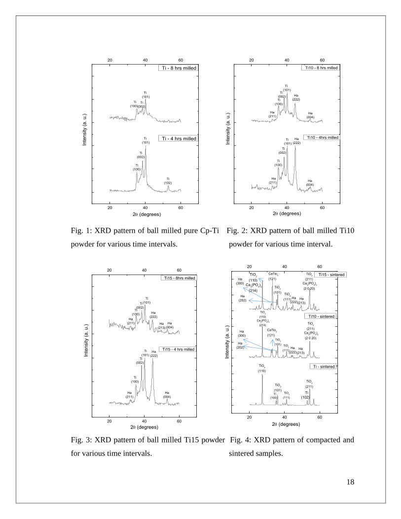
Fig. 1 shows the phase composition of milled pure Cp-Ti powder. The result for
the pure Cp-Ti powder milled for 4 h shows that the peak generally corresponds to Ti
peaks (JCPDS ICDD PDF: 05-0682). No oxide was formed after 4 h of milling. The
XRD pattern of Cp-Ti after 8 h of milling showed decrease in intensity of the Ti peaks.
The peak width of the 8 h ball milled Cp-Ti powder increased indicating refinement of
the crystallite size. No oxide formation or any contaminations from the vials were
observed after 8 h of ball milling. Slight shift in peaks were observed which was due to
strain imposed on the powder due to ball milling.
Fig. 2 shows the XRD pattern of titanium – hydroxyapatite (Ti-Ha) composite mixed in
the % wt. ratio of 90:10 (Ti10). XRD pattern after 4 h of ball milling exhibited both Ti

17
and Ha (JCPDS ICDD PDF: 09-0432) peaks. No contaminations from the vials during
ball milling were observed. XRD pattern of the composite after 8 h milling time shows a
decrease in the intensity of the Ti and Ha peaks. The Ti peaks showed slight broadening
after 8 h of ball milling than 4 h of ball milling indicating the refinement of the particle
size. No oxide formation and contamination were observed after 8 h of ball milling.
Fig. 3 shows the XRD pattern of the Ti-Ha composite with 85:15 % wt. Ti, Ha ratio
(Ti15). XRD pattern after 4 h of ball milling exhibited no contamination from the vials
during ball milling. Ti phase was dominant after 4 h ball milling time. XRD pattern of 8 h
ball milled composite showed a decrease in the intensity of Ti peak. This decrease in the
intensity of Ti peaks shows a refinement of crystal size. The peak broadening with
increase in ball milling time indicates a decrease in crystallite size. Ha intensity decreased
drastically after 8 h of ball milling indicating fusion of Ha in the composite. No oxide
formation and contamination after 8 h ball milling was observed.
4.2.2 Sintered composite characterization
Fig. 4 shows the phase analysis of the compacted, sintered and polished samples
with different Ti-Ha % wt. ratio. Sintering was done at 900oC in muffle furnace in normal
atmosphere. The green compacts were put inside ceramic crucibles and covered with the
ceramic lid. The XRD pattern of sintered pure Cp-Ti showed that sintering at high
temperature in normal atmosphere has led to formation of oxide peaks of Ti. Titanium
has oxidized to its oxide form TiO2 (JCPDS ICDD PDF: 21-1276). TiO2 existed in its
rutile phase. Sintering of Ti10 and Ti15 has led to the oxidation of TiO2. At 900oC,
reaction between Ti and Ha has led to the formation of CaTiO3 (JCPDS ICDD PDF: 22-
153).
18
20 40 60
20 40 60
2 (degrees)
Ti - 4 hrs milled
Ti
(100)
Ti
(002)
Ti
(101)
Ti
(102)
Inte
nsity (
a. u
.)
Ti - 8 hrs milled
Ti
(100)
Ti
(101)
Ti
(002)
20 40 60
20 40 60
Inte
nsity (
a. u
.)
2 (degrees)
Ti10 - 4hrs milled
Ti
(100)
Ti
(002)
Ti
(101)
Ha
(222)
Ha
(004)
Ha
(211)
Ti10 - 8 hrs milled
Ha
(211)
Ti
(100)
Ti
(002)
Ti
(101)
Ha
(222)
Ha
(004)
Fig. 1: XRD pattern of ball milled pure Cp-Ti Fig. 2: XRD pattern of ball milled Ti10
powder for various time intervals. powder for various time interval.
20 40 60
20 40 60
Inte
nsity (
a. u
.)
2 (degrees)
Ti15 - 4 hrs milled
Ha
(211)
Ti
(100)
Ti
(002)
Ti
(101) Ha
(222)
Ha
(004)
Ti15 - 8hrs milled
Ha
(211)
Ti
(100)
Ti
(002)
Ti
(101)
Ha
(222)
Ha
(213)
Ha
(004)
20 40 60
20 40 60
2 (degrees)
Ti - sintered TiO2
(110)
TiO2
(101) TiO
2
(111)
TiO2
(211)
Ti
(100)
Ti
(102)
Inte
nsity (
a. u
.)
Ti10 - sintered TiO
2
(110)
Ca3(PO
4)2
(214)
Ha
(202)
TiO2
(101) TiO2
(111) Ha
(222) Ha
(213)
TiO2
(211)
Ca3(PO
4)2
(2 0 20)
Ha
(300)
CaTio3
(121)
Ti15 - sintered TiO2
(110)
Ca3(PO
4)
2
(214)
Ha
(202)
TiO2
(101) TiO
2
(111) Ha
(222) Ha
(213)
TiO2
(211)
Ca3(PO
4)2
(2 0 20)
Ha
(300)
CaTio3
(121)
Fig. 3: XRD pattern of ball milled Ti15 powder Fig. 4: XRD pattern of compacted and
for various time intervals. sintered samples.

19
Formation of Ca3(PO4)2 (JCPDS ICDD PDF: 09-0169) phase was observed on the
samples. Oxidation of Ti into TiO2 was observed (Fig. 4). Peaks of Ha were observed
after sintering at 900oC, which showed the partial decomposition of Ha at this
temperature. XRD pattern of Ti15 composite shows peaks of TiO2, CaTiO3 and Ha (Fig.
4). The intensity of TiO2 and CaTiO3 peaks increased showing that with increase in Ha
concentration, the oxidation increases and more reaction took place between Ti and Ha.
The peaks of Ca3(PO4)2 also increased showing more decomposition of Ha.
4.2.3. In-vitro bioactivity study in SBF
Fig. 5 shows the XRD pattern of the sintered pure Cp-Ti sample soaked in SBF
for 1 and 2 weeks. XRD plot of the sample soaked in SBF for 1 week shows the
formation of apatite after 1 week immersing in SBF. XRD pattern of the 2 weeks soaked
sample showed that the intensity of Ha peak increased. The intensity of the TiO2 peak
decreased after 2 weeks indicating that more Ha has formed all over sample. Phase of
CaO (JCPDS ICDD PDF: 04-0777) was observed after 2 weeks of soaking. Phase
analysis of the pure Cp-Ti sample before immersion (Fig. 4) shows the presence of TiO2.
The intensity of TiO2 decreased with soaking time indicating formation of apatite on the
sample surface.
Fig. 6 shows the XRD pattern of Ti10 samples soaked in SBF for 1 and 2 weeks. XRD
peaks of the 1 week soaked sample showed the phases of Ha, Ca3(PO4)2 and CaO. The
intensity of these peaks increased with soaking time. Increased peak showed a uniform
deposition of Ha on the sample. No TiO2 peak was observed as in the case of pure Ti
powder sample (Fig. 5). XRD analysis of the Ti10 samples before soaking (Fig. 4)
showed the presence of TiO2 which was now coated with Ha.
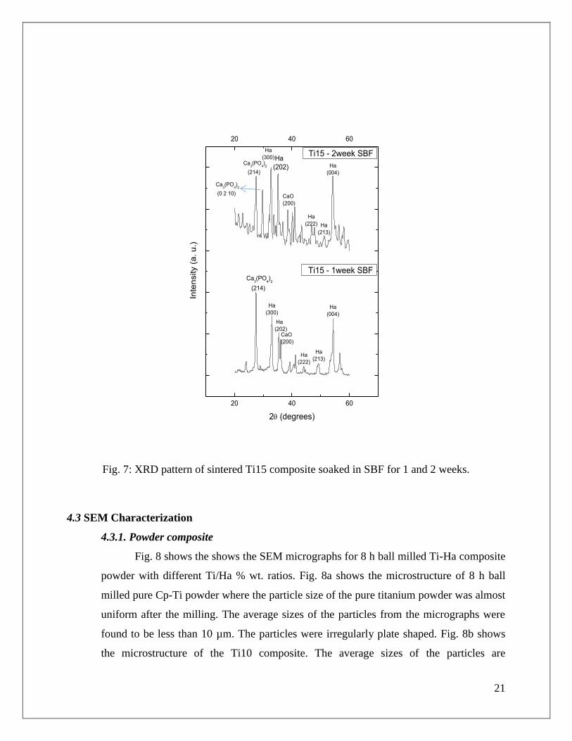
Fig. 7 shows the XRD pattern of Ti15 composite soaked in SBF for 1 and 2 weeks. XRD
pattern of Ti15 samples soaked in SBF for 1 week shows the presence of Ha, Ca3(PO4)2
and CaO phases. With increase in soaking time the intensity of these phases increased
considerably indicating increase in the deposition of Ha on the sample. XRD analysis of

20
samples before coating showed the presence of TiO2 (Fig. 4). However no such TiO2
peaks were found after soaking in SBF.
A comparative study of all the Ti, Ti10 and Ti15 samples soaked in SBF for different
time interval showed that the hydroxyapatite formation was more in Ti15 samples and
least in pure Ti sample. The intensity and distribution of Ha increased with increased in
Ha content in the sample. With increasing time the apatite layer grew thicker as shown in
SEM micrograph (Fig. 10)
20 40 60
20 40 60
Inte
nsity (
a.u
.)
2 (degrees)
Ti_1week SBF
Ca3(PO
4)2
(214)
Ha
(300)
TiO2
(101)
Ha
(213)
Ha
(004)
Ti_2week SBFCa
3(PO
4)2
(214)
Ha
(300)
TiO2
(101)CaO
(200) Ha
(222)
Ha
(004)
20 40 60
20 40 60
2 (degrees)
Ti10 - 1week SBFCa3(PO
4)2
(214)
Ha
(112)
CaO
(200) Ha
(222)
Ha
(004)
Inte
nsity (
a. u
.)
Ti10 - 2week SBFCa3(PO
4)2
(214)
Ha
(300)
Ha
(202)CaO
(200)
Ha
(222)
Ha
(004)
Ha
(213)
Fig. 5: XRD pattern of sintered pure Cp-Ti Fig. 6: XRD pattern of sintered Ti10 composite
soaked in SBF for 1 and 2 weeks. soaked in SBF for 1 and 2 weeks.
21
20 40 60
20 40 60
Inte
nsity (
a. u
.)
2 (degrees)
Ti15 - 1week SBFCa
3(PO
4)
2
(214)
Ha
(300)
Ha
(202)CaO
(200)
Ha
(222)
Ha
(213)
Ha
(004)
Ti15 - 2week SBF
Ha
(004)
Ha
(222) Ha
(213)
Ca3(PO
4)2
(214)
Ca3(PO
4)2
(0 2 10)
Ha
(202)
Ha
(300)
CaO
(200)
Fig. 7: XRD pattern of sintered Ti15 composite soaked in SBF for 1 and 2 weeks.
4.3 SEM Characterization
4.3.1. Powder composite
Fig. 8 shows the shows the SEM micrographs for 8 h ball milled Ti-Ha composite
powder with different Ti/Ha % wt. ratios. Fig. 8a shows the microstructure of 8 h ball
milled pure Cp-Ti powder where the particle size of the pure titanium powder was almost
uniform after the milling. The average sizes of the particles from the micrographs were
found to be less than 10 µm. The particles were irregularly plate shaped. Fig. 8b shows
the microstructure of the Ti10 composite. The average sizes of the particles are
22
comparatively more than those of pure titanium. Fig. 8c shows the microstructure of the
Ti15 milled powder composite. The powder composite showed a more equiaxed particle
structure. The size was more uniform and larger when compared to other composition.
4.3.2. Sintered composite
The sintered composite samples were polished on silicon carbide abrasive paper,
ultrasonicated in acetone and then observed under SEM. Fig. 9a shows the microstructure
of pure Cp-Ti sample. The bright regions shows the extensive oxide layer formed on the
sample as exhibited in the XRD analysis (Fig. 4). Small pores were also observed in the
microstructure. Fig. 9b shows the microstructure of Ti10 composite. With addition of
percent of Ha, the porosity increased. The bright regions also increased in the
microstructure showing an increase in oxide formation. Similar structure was also
observed in Ti15 composite. Fig. 9c shows a more porous structure for Ti15 composite
when compared to other compositions. Porosity increased with increase in Ha
concentration. Fig. 9d shows the cross section of the Ti15 composite. Spherically sized
pores, uniformly distributed throughout the structure can be seen.
4.3.3. In-vitro bioactivity study in SBF
Fig. 10 shows the SEM micrograph of samples with different Ti-Ha % wt. ratio
soaked in SBF for 1 and 2 weeks. Fig. 10a shows the microstructure of pure Ti soaked in
SBF for 1 week. It was observed that globular apatite particles have been deposited on
the sample and more globular apatite was deposited after 2 weeks of immersion (Fig.
10b). Fig. 10c shows the surface of Ti10 samples where more globular apatite was
observed when compared to pure Cp-Ti samples. Increasing the immersion time leads to
the nucleation of more apatite particles. Figure also shows the flaky structures of
Ca3(PO4)2 as exhibited in XRD analysis (Fig. 6). Fig. 10e shows the micrograph of Ti15
samples. The surface of Ti15 is covered with more globular structure as compared to Ti
and Ti10 samples. Also Ti15 sample soaked for 2 weeks showed more apatite nucleated.
A thick layer of apatite can be seen on Ti15 surface soaked in SBF for 2 weeks of
immersion (Fig. 10f). With the increase of immersion time, more apatite deposits and
their size grew gradually forming dense apatite layer.

23
Fig. 8: SEM micrographs of 8 h ball milled composite powder. (a) Pure Cp-Ti powder (b) Ti10
powder (c) Ti15 powder

24
Fig. 9: SEM micrograph of polished and sintered composite. (a) pure Cp-Ti (b) Ti10 composite
(c) Ti15 composite (d) cross section of Ti15 composite

25
Fig. 10: SEM micrographs of ball milled and sintered samples soaked in SBF. (a) Pure Cp-Ti, for
one week (b) pure Cp-Ti, for two weeks (c) Ti10, for one week (d) Ti10, for two weeks (e) Ti15,
for one week (f) Ti15, for two weeks.
26
Chapter 5: Discussion

27
5. Discussion
5.1. Powder composite
High energy ball milling is used to mechanically blend two or more powder materials
into a homogenous mixture of nano and sub micrometer range. In the present study Ti
and Ha of various % wt. were mixed and ball milled to form a Ti-Ha composite and their
bioactivity was studied. High ball milling resulted in the plastic deformation of Ti particles
which resulted in reduction in their crystallite size. During ball milling, repeated cold
welding and fracture takes place. This is also evidenced by XRD pattern as the intensity of Ti
peaks was reduced. Broadening of Ti peaks was observed for increase in milling time (Fig.
1). However some larger particles were depicted in the micrograph. This is due to
agglomeration of particles as a result of ball milling [25].
On addition of Ha to Ti, the composite particles were found to be bigger than those of pure
Ti ball milled powder and spherical in size. Since Ha is brittle material, it was easily ground
to smaller particles. These fine Ha particles have very high surface energy, they tend to stick
to Ti particles and results in the formation of composite powder. The particle size of the
composite Ti15 (Fig. 8c) were larger than those of Ti10 (Fig. 8b) particles due to above
mention mechanism. More Ha content resulted in the formation of larger particles.
The XRD pattern of ball milled Ti-Ha shows no phase other than Ti and Ha (Fig. 2-3). This
is because Ha do not decompose at low temperature. It is highly stable at room temperature.
Also no oxidation of Ti takes place at this temperature. The temperature rise during milling is
not sufficient to carry out such reactions. Also milling was carried out in presence of a
wetting media to minimize the increase in temperature during ball milling. The intensity both
Ti and Ha peaks decreased due to refinement in structure.
5.2. Sintered composite
D. J. Green et. al, defined sintering as a process involving heating a powder assemblage
or other porous structures below their melting point. It produces materials in a robust and
useful form. The porous structure usually undergoes densification and strengthening, as well

28
as developing other required functions [26]. This process is generally used for the materials
having high melting point. Ti has a melting point of 1668oC and that of Ha is 1760
oC. In this
study sintering of Ti-Ha composite was done at 900oC in muffle furnace. XRD pattern of
pure Ti powder (Fig. 4) shows peaks of TiO2. High temperature sintering has resulted in the
oxidation of Ti metal. The oxidation could have been as a result of high temperature sintering
in normal atmosphere. As a well-known fact Ti undergoes an allotropic transformation at
about 890oC which may have resulted in the oxidation of Ti to TiO2. Microstructure of
sintered Ti shows very less pores as the sintering resulted in grain growth which has further
resulted in greater density of the specimen (Fig. 9a).
High temperature sintering of the Ti-Ha composite has initiated reaction between Ti and Ha.
XRD pattern shows the presence of CaTiO3 phase. Phase of Ca3(PO4)2 was found due to the
decomposition of Ha (Fig. 4). The decomposition of Ha could have resulted in to Ca3(PO4)2,
and CaO. The decomposition of Ha could have been initiated by the presence of TiO2 [15].
The samples with Ha content depict large pores which could be due to the dissolution of
CaO. The porous structure increases with increase in Ha content. More Ha content would
have led to the more decomposition and hence more dissolution of CaO (Fig. 9 (b-d)). No Ti
phase in composite containing Ha could be observed because Ti could have either oxidized
or reacted with the decomposition product of Ha to give a new phase, CaTiO3.
The density of the Ti, Ti10 and Ti15 was found to be 3.233, 3.230 and 3.06 g/cc respectively
(Table 3). The decrease in the density with addition of Ha could be a result of dissolution of
CaO, a decomposition product of Ha. The density of the composite was less than that of Ti
(4.51 g/cc). The volume fraction of pores could be calculated from this data. The volume
fraction of pores in Ti, Ti10 and Ti15 were found to be 28.31%, 28.38% and 32.15%
respectively, which has accounted for the porous structure of the Ha containing Ti composite.
This porous structure would enhance osseointegration when implanted in-vivo.
5.3. In-vitro bioactivity study in SBF
SBF is a laboratory developed fluid which has similar inorganic ion concentration as that
of human extracellular fluid, in order to initiate the development of apatite on bioactive
29
materials in-vitro. SBF is used to evaluate the bioactivity of the materials for bone tissues in-
vitro. Though SBF is metastable calcium phosphate solution, it can be stored for almost two
months without any precipitate formation. Hence if apatite has formed on surface of a
material, it is only due to the interaction between the material and SBF. Hydroxyapatite is
formed only if the material is bioactive when immersed in SBF. This apatite forming process
can be interpreted in terms of the surface charge. The titanium composite is initially
negatively charged, and hence combines with positively charged calcium ions in SBF to form
a calcium titanate. As the calcium ions are accumulated, the surface is positively charged and
hence combines with negatively charged phosphate ions to form an amorphous calcium
phosphate with low Ca/P ratio (~1.48). This phase is metastable and hence eventually
transforms into crystalline bone-like apatite with Ca/P ratio almost similar to that of bone
(~1.66). The apatite globules were much larger and densely packed when compared to all
other conditions.
Microstructure of the composite soaked in SBF for 1 and 2 weeks shows the globular apatite
formed on the surface (Fig. 10). Ti15 shows the maximum apatite grown on its surface (Fig.
10 (e-f)). Ca3 (PO4)2 is one of important biomaterial owing to its high bioactivity [15]. This
may be a possible reason to induce apatite formation on the surface of Ti10 and Ti15.
The existence of CaO could also induce apatite nucleation. Supersaturation of SBF with
respect to calcium phosphate will increase which will lead to decrease in the free energy for
the formation of embryo with critical size, which favors nucleation and growth of apatite [4].
TiO2 reacts with water to form Ti-OH. This Ti-OH on the surface may provide specific
favorable site for apatite formation due to lower free energy for apatite nucleation. Fig. 10b,
Fig. 10d, Fig. 10f shows increased apatite coated on the surface with increase in time. Once
the apatite nuclei have formed, they can grow over time by consuming the calcium and
phosphate ions from SBF. This is shown by the increase in diffraction intensity of immersed
sample after 2 weeks (Fig. 5-7).

30
Chapter 6: conclusion

31
Ti-Ha composite was successfully prepared by powder metallurgical route using a high energy
ball milling and subsequent sintering. Density and bioactivity of the sintered samples were
assessed in simulated body fluid. From the study the following conclusions are drawn.
1) The sintered sample showed more porous structure with increase in Ha content. The
volume fraction of pores was found to be more in Ti15 composite.
2) Sintering at 900 oC resulted in partial decomposition of Ha. At this temperature, reaction
between Ti and Ha occurred resulting in the formation of CaTiO3 which initiates more
apatite formation. Ca3(PO4)2 and TiO2 were detected from XRD analysis which favors
apatite formation.
3) The composite containing hydroxyapatite showed better bioactivity than pure Cp-Ti and
the hydroxyapatite deposition increased with increase in Ha content when immersed in
SBF for the same time period (1 week).

32
References

33
References
1. M. Geetha, A.K. Singh, R. Asokamani and A.K. Gogia. Ti based biomaterials, the
ultimate choice for orthopaedic implants – A review. (2009), Progress in Materials
Science, Vol. 54, pp. 397–425.
2. S. R. Paital and N. B. Dahotre. Calcium phosphate coatings for bio-implant
applications: Materials, performance. (2009), Materials Science and Engineering R, Vol.
6, pp. 1-70.
3. C. Ning and Y. Zhoub. Correlations between the in vitro and in vivo bioactivity of the
Ti/HA composites fabricated by a powder metallurgy method. (2008), Acta Biomaterialia,
Vol. 4, pp. 1944-1952.
4. C.Q. Ning and Y. Zhou. In vitro bioactivity of a biocomposite fabricated from HA and
Ti powders by powder metallurgy method. (2002), Biomaterials, Vol. 23, pp. 2909-2915.
5. Q. Chang, H.Q. Ru, D.L. Chen, X.Y. Yue, L. Yu and C.P. Zhang. An in-vitro
Investigation of Iron-Containing Hydroxyapatite/Titanium Composites. (2011), J. Mater.
Sci. Technol, Vol. 27, pp. 546-552.
6. E.J. Giordani, V.A. Guimaraes, T.B. Pinto and I. Ferreira. Effect of precipitates on
the corrosion–fatigue crack initiation of ISO-5832-9 stainless steel biomaterial. 2004,
International Journal of Fatigue, Vol. 26, pp. 1129-1136.
7. S. Hong-fei, L. Cheng-jie and F. Wen-bin. Corrosion behavior of extrusion-drawn pure
Mg wire immersed in simulative body fluid. (2011), Trans. nonferrous Met. Soc. China,
Vol. 21, pp. 258-261.
8. X. Cui, Y. Yang, E. Liu, G. Jin, J. Zhong and Q. Li. Corrosion behaviors in
physiological solution of cerium conversion coatings on AZ31 magnesium alloy. (2011),
Applied Surface Science, Vol. 257, pp. 9703-9709.

34
9. C.L. Chu, R.M. Wang, T. Hu, L.H. Yin , Y.P. Pu , P.H. Lin , S.L. Wu, C.Y. Chung,
K.W.K. Yeung and P. K. Chu. Surface structure and biomedical properties of
chemically polished and electropolished NiTi shape memory alloys. (2008), Materials
Science and Engineering C, Vol. 28, pp. 1430-1434.
10. A. Shahrjerdi, F. Mustapha, M. Bayat, S. M. Sapuan and D. L. A. Majid.
Fabrication of functionally graded Hydroxyapatite-Titanium by applying optimal
sintering procedure and powder metallurgy. (2011), International Journal of the Physical
Sciences, Vol. 6, pp. 2258-2267.
11. J. G. Lee, S.M. Hong, J.J. Park, M.K. Lee, S.J. Hong, U.H. Joo and C.K. Rhee. High
energy ball-mill behavior of titania + hydroxyapatite composite nano-powders. (2010),
Materials Characterization, Vol. 61, pp. 1290-1293.
12. Anawati, H. Tanigawa, H. Asoh, T. Ohno, M. Kubota and S. Onoa. Electrochemical
corrosion and bioactivity of titanium–hydroxyapatite composites prepared by spark
plasma sintering. (2013), Corrosion Science, Vol. 70, pp. 212-220.
13. W. Shi, A. Kamiya, J. Zhu and A. Watazu. Properties of titanium biomaterial
fabricated by sinter-bonding of titanium/hydroxyapatite composite surface-coated layer
to pure bulk titanium. (2002), Materials Science and Engineering: A, Vol. 337, pp. 104 -
109.
14. C.Q. Ning and Y. Zhou. On the microstructure of biocomposites sintered from Ti,HA
and bioactive glass. (2004), Biomaterials, Vol. 25, pp. 3379-3387.
15. G. Zhao, L. Xia, G. Wen, L. Song, X. Wang and K. Wu. Microstructure and
properties of plasma-sprayed bio-coatings on a low-modulus titanium alloy from milled
HA/Ti powders. (2012), Surface and Coatings Technology, Vol. 206, pp. 4711-4719.
35
16. C. Chenglin, Z. Jingchuan, Y. Zhongda and W. Shidong. Hydroxyapatite–Ti
functionally graded biomaterial fabricated by powder metallurgy. (1999), Materials
Science and Engineering: A, Vol. 271, pp. 95-100.
17. S. Salman, O. Gunduz, S. Yilmaz, M.L. Öveçoğlu, Robert L. Snyder, S.
Agathopoulos and F.N. Oktar. Sintering effect on mechanical properties of composites
of natural hydroxyapatites and titanium. (2009), Ceramics International, Vol. 35, pp.
2965-2971.
18. A. Siddharthan, T.S. Sampath Kumar and S.K. Seshadri. In situ composite coating of
titania–hydroxyapatite on commercially pure titanium by microwave processing. (2010),
Surface and Coatings Technology, Vol. 204, pp. 1755-1763.
19. Q. Chang, D.L. Chen, H.Q. Ru, X.Y. Yue, L. Yu and C.P. Zhang. Toughening
mechanisms in iron-containing hydroxyapatite/titanium composites. (2010),
Biomaterials, Vol. 31, pp. 1493-1501.
20. W. Que, K.A. Khor, J.L. Xu and L.G. Yu. Hydroxyapatite/titania nanocomposites
derived by combining high-energy ball milling with spark plasma sintering processes.
(2008), Journal of the European Ceramic Society, Vol. 28, pp. 3083-3090.
21. X. Zhou and P. Mohanty. Electrochemical behavior of cold sprayed
hydroxyapatite/titanium composite in Hanks’ solution. (2012), Electrochimica Acta, Vol.
65, pp. 134– 140.
22. X. Zheng, , M. Huang and C. Ding. Bond strength of plasma-sprayed hydroxyapatite/Ti
composite coatings. (2000), Biomaterials, Vol. 21, pp. 841-849.

36
23. C. Chu, X. Xue, J. Zhu and Z. Yin. In vivo study on biocompatibility and bonding
strength of Ti/Ti–20 vol.% HA/Ti–40 vol.% HA functionally graded biomaterial with
bone tissues in the rabbit. (2006), Materials Science and Engineering: A, Vol. 429, pp.
18-24.
24. T. Kokubo and H. Takadama. How useful is SBF in predicting in vivo bone
bioactivity? (2006), Biomaterials, Vol. 27, pp. 2907–2915.
25. Suryanarayana, C. Mechanical alloying and milling. (2001), Progress in Materials
Science, Vol. 46, pp. 1-184.
26. D. J. Green, O. Guillion, J Rodel. Constrained sintering: A delicate balance of scales.
( 2008 ), Journal of the European Ceramic Society, Vol. 28, pp. 1451–1466.