Systems Engineering Life Cycle and Systems Engineering Processes.

© 2001 by CRC Press LLC
24
Processes for
Engineering a System
24.1 Introduction.
24.2 Structure of the Standard
24.3 Role of the EIA 632 Standard
24.4 Heritage of EIA 632
24.5 The Processes
Process Hierarchy • Technical Management Processes • Acquisition and Supply Processes • System Design Processes • Product Realization Processes • Technical Evaluation Processes
24.6 Project Context
24.7 Key Concepts
The System and Its Products • Building Block Framework • Development of Enabling Products • Relationship Between the Building Blocks and the Processes • Hierarchy of Building Blocks • Requirements • Functional, Performance, and Interface Requirements • Verification and Validation
Defining Terms
References
Further Information
24.1 Introduction
In April 1995, the G47 Systems Engineering Committee of the Electronic Industries Alliance (EIA)chartered a working group to convert the interim standard EIA/IS 632 into a full standard. This fullstandard was developed and released in December 1998 as ANSI/EIA-632-1998.
The interim standard (IS), EIA/IS 632, was titled “Systems Engineering.” The full standard wasexpanded in scope to include
all the technical processes for engineering a system
. It is intended to be ahigher-level abstraction of the activities and tasks found in the IS version plus those other technicalactivities and tasks deemed to be essential to the engineering of a system.
This chapter describes the elements of these processes and related key concepts. The intended purposeis to give the reader of the standard some background in its development and to help other standardsactivities in developing their own standard. There is a paper that describes the evolution from an interimstandard to the full standard [Martin, 1998].
This standard is intended to be a “top tier” standard for the
processes essential to engineering a system
.It is expected that there will be second- and third-tier standards that define specific practices related to
James N. Martin
The Aerospace Corporation

© 2001 by CRC Press LLC
certain disciplines (e.g., systems engineering, electrical engineering, software engineering) and industrydomains (e.g., aircraft, automotive, pharmaceutical, building, and highway construction).
It is important to understand several things that are
not
covered by this standard:
1. It does
not
define what “systems engineering” is;2. It does
not
define what a “systems engineer” is supposed to do; and3. It does
not
define what a “systems engineering organization” is supposed to do.
24.2 Structure of the Standard
The standard is organized as shown below:
Clause 1
Scope
Clause 2
Normative references
Clause 3
Definitions and acronyms
Clause 4
Requirements
Clause 5
Application context
Clause 6
Application key concepts
Annex A
Glossary
Annex B
Enterprise-based life cycle
Annex C
Process task outcomes
Annex D
Planning documents
Annex E
System technical reviews
Annex F
Unprecedented and precedented development
Annex G
Requirement relationships
24.3 Role of the EIA 632 Standard
Implementation of the requirements of EIA 632 are intended to be through establishment of enterprisepolicies and procedures that define the requirements for application and improvement of the adoptedprocesses from the standard. This is illustrated in Figure 24.1.
24.4 Heritage of EIA 632
Figure 24.2 shows the relationship between EIA 632 and other standards on systems engineering. Someof the key software engineering standards are shown for comparison since there has been an intimaterelationship between the development of both types of standards. There has been much activity recentlyin unifying the processes contained in each.
FIGURE 24.1
Role of the standard in relation to development projects. (Adapted from ANSI/EIA-632-1998. Withpermission.)

© 2001 by CRC Press LLC
24.5 The Processes
Figure 24.3 shows the processes described in EIA 632 and their relationship to one another. Eachenterprise will determine which of these processes are implemented by systems engineering personnel,and how they are allocated to the organizational elements of the enterprise and its functional disciplines.
24.5.1 Process Hierarchy
The processes for engineering a system are grouped into the five categories as shown in Figure 24.4. Thisgrouping was made for ease of organizing the standard and is not a required structure for processimplementation. Traditional systems engineering is most often considered to include two of these pro-cesses: Requirements Definition and Systems Analysis. Often, Planning and Assessment are included inwhat is called systems engineering management.
24.5.2 Technical Management Processes
Technical Management provides oversight and control of the technical activities within a developmentproject. The processes necessary to accomplish this are shown in Figure 24.5.
24.5.3 Acquisition and Supply Processes
Acquisition and Supply provides the mechanism for a project to supply its own products to a customeror higher-level project and to acquire the necessary products for its own product development activities.The processes necessary to accomplish this are shown in Figure 24.6.
24.5.4 System Design Processes
System Design provides the activities for a project to define the relevant requirements for its productdevelopment effort and to design solutions that meet these requirements. The processes necessary toaccomplish this are shown in Figure 24.7.
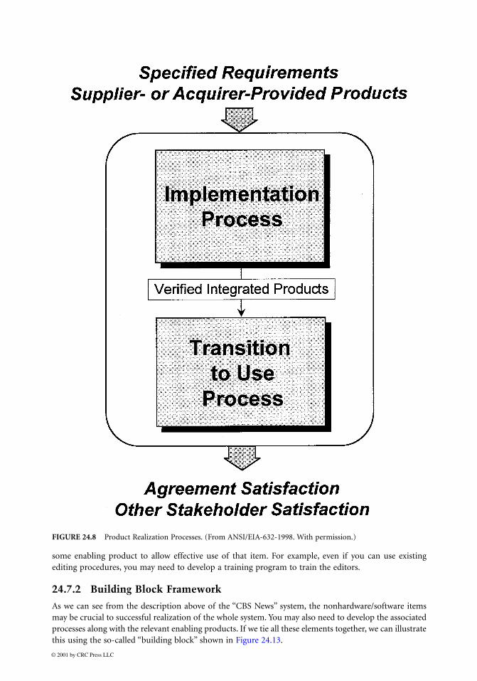
24.5.5 Product Realization Processes
Product Realization provides the activities for a project to implement the product designs and to transitionthese products to their place of use. The processes necessary to accomplish this are shown in Figure 24.8.
FIGURE 24.2
Heritage of systems engineering standards.

© 2001 by CRC Press LLC
24.5.6 Technical Evaluation Processes
Technical Evaluation provides activities for a project to analyze the effectiveness of its proposed designs,validate the requirements and end products, and to verify that the system and its product meet thespecified requirements. The processes necessary to accomplish this are shown in Figure 24.9.
24.6 Project Context
These “technical” processes fit into a larger context of a project (see Figure 24.10), and the project residesin some sort of enterprise, which in turn resides in an environment external to the enterprise. There areprocesses in the project and within the enterprise (but outside the project) that significantly affect thesuccessful implementation of the technical processes.
FIGURE 24.3
Top-level view of the processes for engineering a system. (From ANSI/EIA-632-1998. With permission.)

© 2001 by CRC Press LLC
24.7 Key Concepts
To understand the processes as described in this standard, it is essential to understand the distinct useof certain terms and the conceptual models that underlie each process. Some of the key terms are system,product, verification, and validation. Some of the key concepts are building block, end products, asso-ciated processes, and development layers.
24.7.1 The System and Its Products
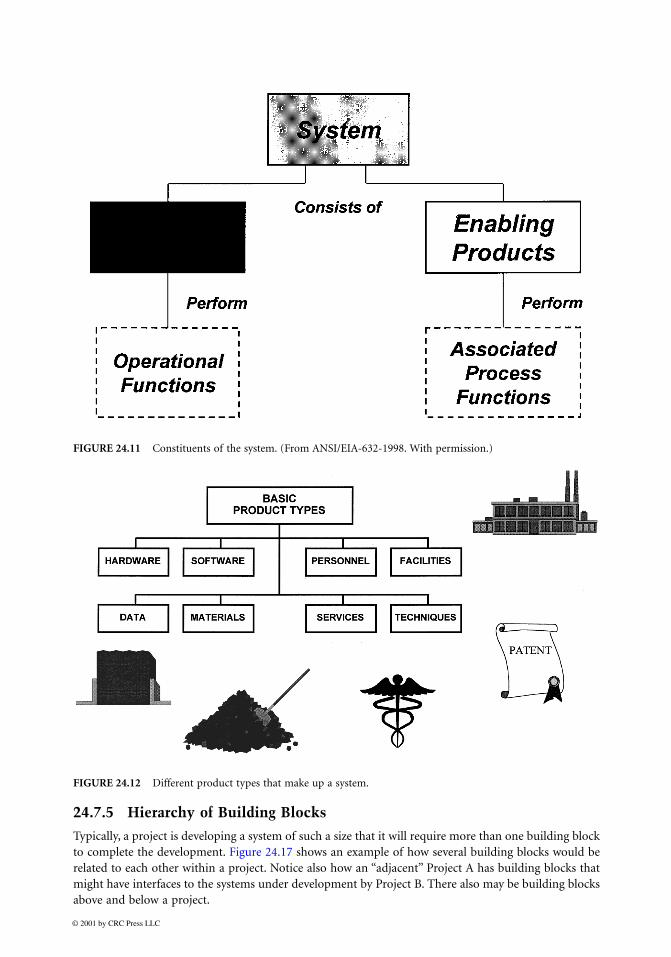
What is a system? The term “system” is commonly used to mean the set of hardware and softwarecomponents that are developed and delivered to a customer. This standard uses this term in a broadersense in two aspects.
First, the system that needs to be developed consists of not only the “operations product” (that whichis delivered to the customer and used by a user), but also the enabling products associated with thatoperations product. The operations product consists of one or more end products (so-called since theseare the elements of the system that “end up” in the hands of the ultimate user). The associated processesare performed using enabling products that “enable” the end products to be put into service, kept inservice, and retired from service.
Second, the end products that need to be developed often go beyond merely the hardware and softwareinvolved. There are also people, facilities, data, materials, services, and techniques. This is illustrated inFigure 24.12.
FIGURE 24.4
Hierarchical view of the processes for engineering a system. (From ANSI/EIA-632-1998. With per-mission.)

© 2001 by CRC Press LLC
This is not intended to be an exhaustive list of the “basic” product types since these will vary dependingon the particular business or technology domain. For example, in the television industry, “media” iscertainly one of the system elements that constitute the overall system that is developed. “CBS News”might be considered the system, for example, with end products like:
Airwaves, worldwide web (media)Cameras, monitors (hardware)Schedule management tools, video compression algorithms (software)Camera operators, news anchor (personnel)Studio, broadcasting tower (facilities)Script, program guide (data)Pictures, stories (materials)Airplane transportation, telephone (services)Presentation method, editing procedures (techniques)
Note that any or all of these end products could be “off-the-shelf.” But some of them may need to beconceived, designed, and implemented. Even if one of these items is truly off-the-shelf, it may still need
FIGURE 24.5
Technical Management Processes. (From ANSI/EIA-632-1998. With permission.)

© 2001 by CRC Press LLC
FIGURE 24.6
Acquisition and Supply Processes. (From ANSI/EIA-632-1998. With permission.)
FIGURE 24.7
System Design Processes. (From ANSI/EIA-632-1998. With permission.)
© 2001 by CRC Press LLC
some enabling product to allow effective use of that item. For example, even if you can use existingediting procedures, you may need to develop a training program to train the editors.
24.7.2 Building Block Framework
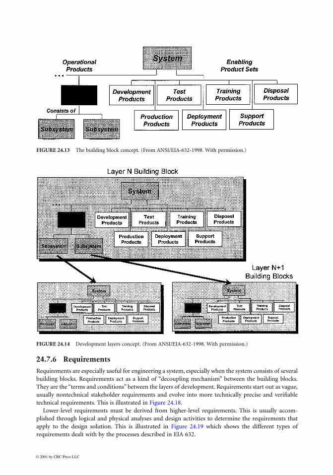
As we can see from the description above of the “CBS News” system, the nonhardware/software itemsmay be crucial to successful realization of the whole system. You may also need to develop the associatedprocesses along with the relevant enabling products. If we tie all these elements together, we can illustratethis using the so-called “building block” shown in Figure 24.13.
FIGURE 24.8
Product Realization Processes. (From ANSI/EIA-632-1998. With permission.)

© 2001 by CRC Press LLC
There are seven associated processes related to these sets of enabling products. These processes areused at various points in the life of a product (sometimes called “system life cycle elements”). Hence, theuse of the building block concept is intended to help the developer in ensuring that the full life cycle ofthe end product is properly considered.
Note that each end product can consist of subsystems. Each of these subsystems may need its owndevelopment. The building block can be used at the various “development layers” of the total system.These development layers are illustrated in Figure 24.14.
24.7.3 Development of Enabling Products
As mentioned above, the enabling products may need to be developed also. For each associated process,there could be enabling products that either exist already or that need some degree of development.Figure 24.15 shows how enabling products related to the deployment process have their own buildingblocks.
24.7.4 Relationship Between the Building Blocks and the Processes
The building blocks relevant to a particular system development can be “stacked” into a System Break-down Structure (SBS). The System Design Process and Verification and Validation Processes have a specialrelationship to the SBS, as shown in Figure 24.16.
FIGURE 24.9
Technical Evaluation Processes. (From ANSI/EIA-632-1998. With permission.)

© 2001 by C
RC
Press LL
C
FIGURE 24.10
The technical processes in the context of a project and an enterprise. (From ANSI/EIA-632-1998. With permission.)
© 2001 by CRC Press LLC
24.7.5 Hierarchy of Building Blocks
Typically, a project is developing a system of such a size that it will require more than one building blockto complete the development. Figure 24.17 shows an example of how several building blocks would berelated to each other within a project. Notice also how an “adjacent” Project A has building blocks thatmight have interfaces to the systems under development by Project B. There also may be building blocksabove and below a project.
FIGURE 24.11
Constituents of the system. (From ANSI/EIA-632-1998. With permission.)
FIGURE 24.12
Different product types that make up a system.
© 2001 by CRC Press LLC
24.7.6 Requirements
Requirements are especially useful for engineering a system, especially when the system consists of severalbuilding blocks. Requirements act as a kind of “decoupling mechanism” between the building blocks.They are the “terms and conditions” between the layers of development. Requirements start out as vague,usually nontechnical stakeholder requirements and evolve into more technically precise and verifiabletechnical requirements. This is illustrated in Figure 24.18.
Lower-level requirements must be derived from higher-level requirements. This is usually accom-plished through logical and physical analyses and design activities to determine the requirements thatapply to the design solution. This is illustrated in Figure 24.19 which shows the different types ofrequirements dealt with by the processes described in EIA 632.
FIGURE 24.13
The building block concept. (From ANSI/EIA-632-1998. With permission.)
FIGURE 24.14
Development layers concept. (From ANSI/EIA-632-1998. With permission.)

© 2001 by CRC Press LLC
FIGURE 24.15
Development of enabling products. (Adapted from ANSI/EIA-632-1998. With permission.)
FIGURE 24.16
Development layers in a project context. (Adapted from ANSI/EIA-632-1998. With permission.)

© 2001 by C
RC
Press LL
C
FIGURE 24.17
Building blocks in the context of a several projects. (From ANSI/EIA-632-1998. With permission.)

© 2001 by CRC Press LLC
Requirements generally do not come from a particular customer. And even when they do, as is oftenthe case in government-sponsored developments, they do not represent the full spectrum of the require-ments that will eventually need to be defined for development of the products of a system.
User Requirements.
User requirements are often nontechnical in nature and usually conflict with eachother. These need to be translated into “technical requirements” that are in the vernacular of theengineers on a project and are specific to the domain of the technology to be used in the system.
FIGURE 24.18
Evolution of requirements. (
Source
: ANSI/EIA-632-1998. With permission.)
FIGURE 24.19
Types of requirements and their interrelationships. (From ANSI/EIA-632-1998. With permission.)

© 2001 by CRC Press LLC
Customer Requirements.
Customers will often translate their perceived user requirements into a setof requirements to be given to a development project. These also, like the user requirements, areoften not technical enough and usually conflict with each other. Moreover, a particular projectmay have more than one customer for its products.
Stakeholder Requirements.
In defining the technical requirements for the system, one must considerthat there are other stakeholders for that system. For example, the manufacturing organizationwithin your company may desire that you use their existing processes, tools, facilities, etc. Thereare constraints associated with these “enabling products.” Hence, you must identify the stakeholderrequirements that drive the development.
Requirements Decomposition.
Once the system technical requirements are defined, further require-ments are often “derived” by analyzing both the logical and physical aspects of the system. Someof these derived requirements, plus whatever system technical requirements are relevant, are“specified” for the system, its end products, and possibly subsystems of those end products.
Given these specified requirements for an item, the process starts all over again for items needingfurther development. In other words, another layer of building blocks may be required to develop anitem far enough along such that the bottommost item can be procured from a supplier. This is illustratedin Figure 24.20.
24.7.7 Functional, Performance, and Interface Requirements
Another way to look at requirements is to categorize them as functional (what the product must accom-plish), performance (how well the product must accomplish each function), and interface (under whatconditions must the functions be accomplished). This is illustrated in Figure 24.21.
FIGURE 24.20
Layers of requirements as they relate to the layers of development. (Adapted from ANSI/EIA-632-1998. With permission.)

© 2001 by CRC Press LLC
24.7.8 Verification and Validation
Verification and validation are both very important in engineering a system. Verification is the act ofdetermining if a product meets its specified requirements. Validation is the act of determining if a productsatisfies its stakeholders. This is illustrated in Figure 24.22
Defining Terms
The following definitions are extracted from the standard.
Building block:
A representation of the conceptual framework of a system that is used for organizingthe requirements, work, and other information associated with the engineering of a system. Anelement in the structured decomposition of the system.
Enabling product:
Item that provides the means for (a) getting an end product into service, (b) keepingit in service, or (c) ending its service.
End product:
The portion of a system that performs the operational functions and is delivered to anacquirer.
Process:
A set of interrelated tasks that, together, transform inputs into outputs.
Product:
(1) An item that consists of one or more of the following: hardware, software, firmware,facilities, data, materials, personnel, services, techniques, and processes; (2) a constituent part ofa system.
Requirement:
Something that governs what, how well, and under what conditions a product willachieve a given purpose.
Stakeholder:
An enterprise, organization, or individual having an interest or a stake in the outcomeof the engineering of a system.
Subsystem:
A grouping of items that perform a set of functions within a particular end product.
System:
An aggregation of end products and enabling products to achieve a given purpose.
Validation:
(1) Confirmation by examination and provision of objective evidence that the specificintended use of an end product (developed or purchased), or an aggregation of end products, is
FIGURE 24.21
Types of requirements.

© 2001 by CRC Press LLC
accomplished in an intended usage environment; (2) confirmation by examination that require-ments (individually and as a set) are well formulated and ar usable for intended use.
Verification:
Confirmation by examination and provision of objective evidence that the specifiedrequirements to which an end product is built, coded, or assembled have been fulfilled.
References
ANSI/EIA 632,
Processes for Engineering a System
. 1998.EIA/IS 632,
Systems Engineering
. 1994.Martin, J. N., “Evolution of EIA 632 from an Interim Standard to a Full Standard.” Proc. INCOSE 1998
Int. Symp., 1998.
Further Information
The purpose of this chapter is to give a high-level overview of the processes for engineering a systemdescribed in ANSI/EIA 632. Further details can be found in the full publication of the standard or bycontacting the EIA directly at 2500 Wilson Boulevard, Arlington, Virginia or at their Website(www.eia.org).
FIGURE 24.22
Distinction between verification and validation.