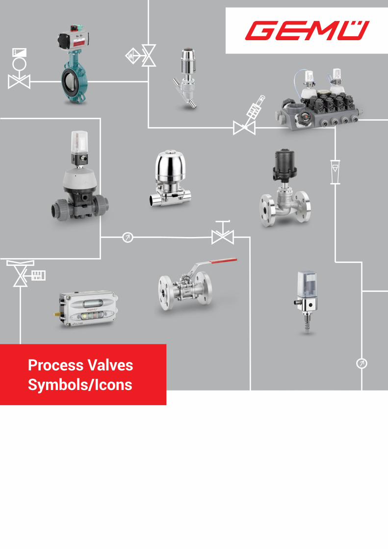
Process Valves Symbols/Icons
50
P Process Valves Symbols/Icons
Transcript of Process Valves Symbols/Icons
P
Process Valves Symbols/Icons
2
Table of contents
Explanation Important information . . . . . . . . . . . . . . . . . . . . . . . . . . . . . . . . . . 3
Key . . . . . . . . . . . . . . . . . . . . . . . . . . . . . . . . . . . . . . . . . . . . . . . . . . 4
Example of an operational scheme . . . . . . . . . . . . . . . . . . . . . . 5
Symbols for process valves . . . . . . . . . . . . . . . . . . . . . . . . . . . . . 6
Symbols for actuators . . . . . . . . . . . . . . . . . . . . . . . . . . . . . . . . . . 7
Additional symbols . . . . . . . . . . . . . . . . . . . . . . . . . . . . . . . . . . . . 8
Positioners/process controllers . . . . . . . . . . . . . . . . . . . . . . . . . 9
Examples . . . . . . . . . . . . . . . . . . . . . . . . . . . . . . . . . . . . . . . . . . . . 10
Straight seat 2/2-way globe valves in straight design . . . . . . . . . . . . . . . . . . . . . . . . . . . . . . . . . . . . . 11
Angle seat 2/2-way globe valves in straight design . . . . . . . . . . . . . . . . . . . . . . . . . . . . . . . . . . . . . 12
3/2-way double-seat globe valves in multi-port design . . . . . . . . . . . . . . . . . . . . . . . . . . . . . . . . . . . 13
2/2-way globe valves in angled design . . . . . . . . . . . . . . . . . . . . . . . . . . . . . . . . . . . . . . 14
2/2-way diaphragm valves in weir type, with straight through body . . . . . . . . . . . . . . . . . 15
2/2-way diaphragm valves in weir type, for tank installation . . . . . . . . . . . . . . . . . . . . . . . 16
2/2-way diaphragm valves in weir type, with angle valve body . . . . . . . . . . . . . . . . . . . . . . 17
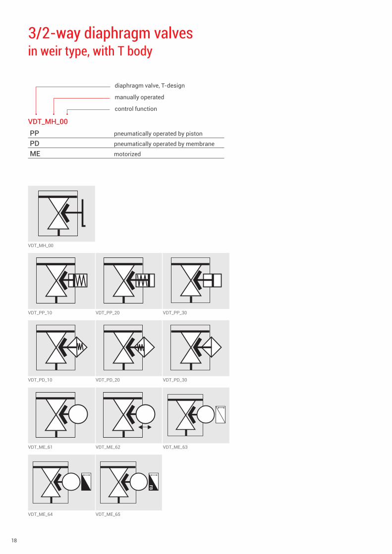
3/2-way diaphragm valves in weir type, with T body . . . . . . . . . . . . . . . . . . . . . . . . . . . . . . . 18
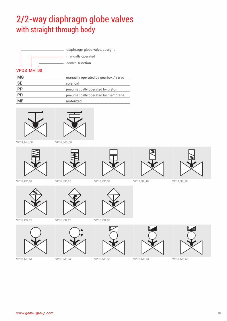
2/2-way diaphragm globe valves with straight through body . . . . . . . . . . . . . . . . . . . . . . . . . . . . . 19
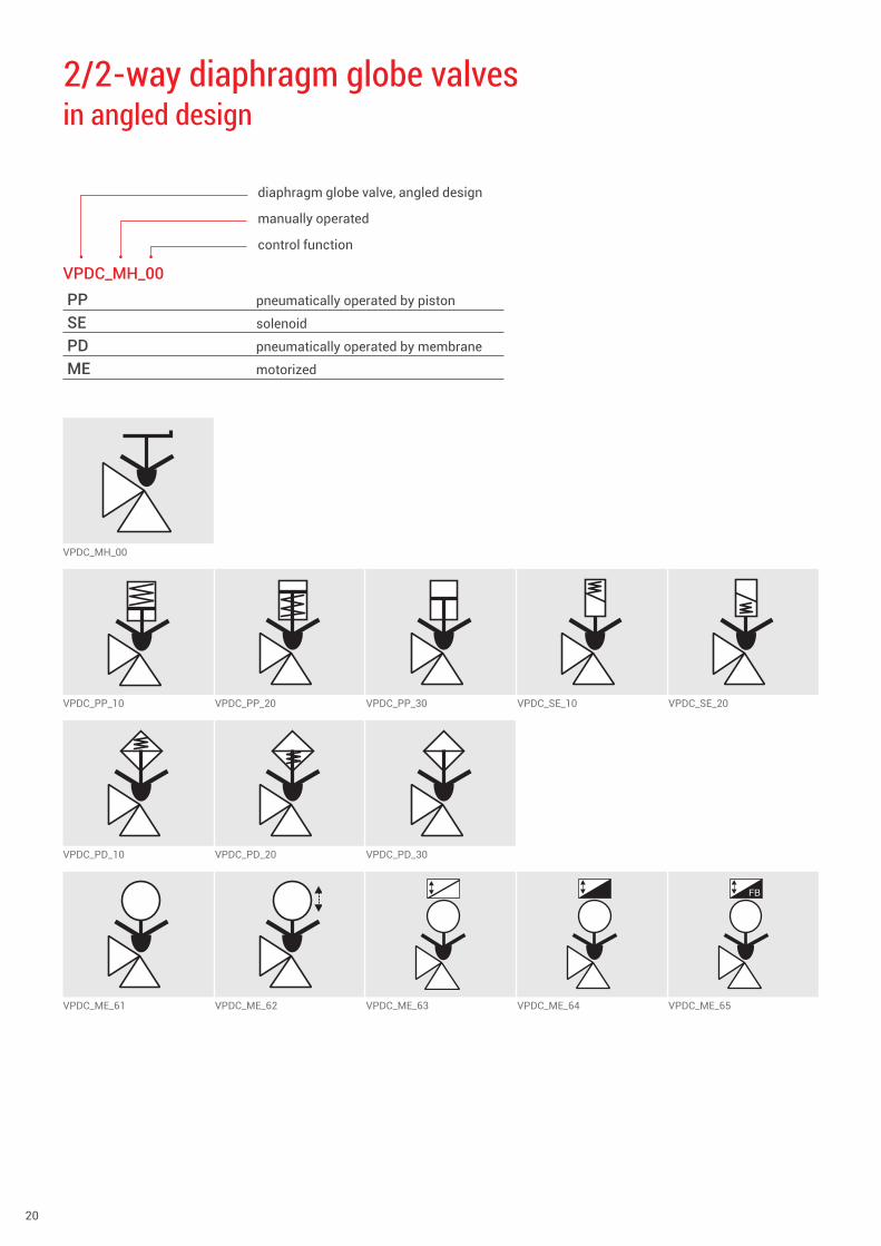
2/2-way diaphragm globe valves in angled design . . . . . . . . . . . . . . . . . . . . . . . . . . . . . . . . . . . . . . 20
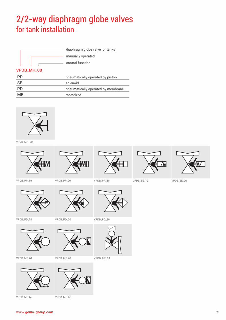
2/2-way diaphragm globe valves for tank installation . . . . . . . . . . . . . . . . . . . . . . . . . . . . . . . . . . . 21
3/2-way diaphragm globe valves with T body . . . . . . . . . . . . . . . . . . . . . . . . . . . . . . . . . . . . . . . . . . 22
2/2-way diaphragm valves Full bore design, with straight through body . . . . . . . . . . . . . 23
2/2-way ball valves in straight design . . . . . . . . . . . . . . . . . . . . . . . . . . . . . . . . . . . . . 24
3/2-way ball valves with T-port, in multi-port design . . . . . . . . . . . . . . . . . . . . . . . . 25
3/2-way ball valves with L-port, in multi-port design . . . . . . . . . . . . . . . . . . . . . . . . 26
2/2-way butterfly valves in straight design . . . . . . . . . . . . . . . . . . . . . . . . . . . . . . . . . . . . . 27
2/2-way check valves Swing check valve, in straight design . . . . . . . . . . . . . . . . . . . 28
2/2-way gate valves in straight design . . . . . . . . . . . . . . . . . . . . . . . . . . . . . . . . . . . . . 29
2/2-way pinch valves in straight design . . . . . . . . . . . . . . . . . . . . . . . . . . . . . . . . . . . . . 30
2/2-way plug valves in straight design . . . . . . . . . . . . . . . . . . . . . . . . . . . . . . . . . . . . . 31
3/2-way plug valves with T-port, in multi-port design . . . . . . . . . . . . . . . . . . . . . . . . 32
3/2-way plug valves with L-port, in multi-port design . . . . . . . . . . . . . . . . . . . . . . . . 33
Measurement devices . . . . . . . . . . . . . . . . . . . . . . . . . . . . . . . . . 34
Representation of manual valves Examples . . . . . . . . . . . . . . . . . . . . . . . . . . . . . . . . . . . . . . . . . . . . 35
The use of the valve symbols in Technical Communication and its procurement . . . . . . . . . . . . . . . . . . . 39
Examples Diaphragm valves and globe valves attribute recording 40–43
Examples Butterfly valves attribute recording . . . . . . . . . . . . . . . . . .44–45
Examples Ball and plug valves attribute recording . . . . . . . . . . . . . . . . . 46
Strong together through knowledge The new three-level GEMÜ training system . . . . . . . . . . . . . . 47
www.gemu-group.com 3
New logical symbols for process valvesAt the request of the plant designers and design engineers, we must address the question of workably collating the symbols for process valves from the wealth of existing standards and records . It transpires that a wide range of symbolism does indeed exist within the various standards, but this is especially pronounced for the respective scope of application of the standard (e .g . standard for fire protection equipment DIN 19 227 Part 2, standard for thermal power plants DIN 2481, EN ISO 10 628, EN 62424/ISO 3511 and ISA 5 .1 . Flow chart for processing plants) . Sometimes different representations are defined there for the same valve and actuation type . The existing attributes are frequently insufficient and the focus is in another place in accordance with the respective standard . For this reason, the gap was bridged specially for the requirements of process engineering plant engineering and the area of process valve technology, and a new symbolism developed tailored to this area of application .
DesignsTo support CAD systems, the symbols are also made available in electronic format for download: www .gemu-group .com/download&support .
CopyrightCopyright and right of use belong to GEMÜ Gebrüder Müller GmbH & Co . KG, Fritz-Müller-Straße 6–8, 74653 Ingelfingen-Criesbach, Germany .
Right of useWith this, permission/approval is granted free of charge for personal private and commercial exploitation and for planning and representation of plants in any form, as well as passing on to third parties for this purpose (user group 1) . Exempt from this are competitors/rivals of GEMÜ and man-ufacturers/distributors of process valves and control valves (user group 2) .
Upon specifying the precise intended use, chargeable per-mission/partial permission/approval can be applied for from GEMÜ Global Marketing . Permission/approval for publication in brochures, prospectuses, magazines, books, other printed materials and electronic media must likewise be applied for from GEMÜ Global Marketing (user group 1 and 2) . All rights reserved .
Explanation Important information
4
Key
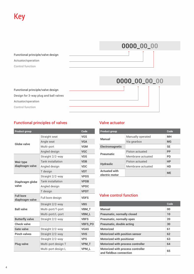
0000_00_00
0000_00_00_00
Functional principle/valve design
Actuator/operation
Control function
Functional principle/valve design
Design for 3-way plug and ball valves
Actuator/operation
Control function
Functional principles of valves
Product group Code
Globe valve
Straight seat VGS
Angle seat VGA
Multi-port VGM
Angled design VGC
Weir type diaphragm valve
Straight 2/2-way VDS
Tank installation VDB
Angled design VDC
T design VDT
Diaphragm globe valve
Straight 2/2-way VPDS
Tank installation VPDB
Angled design VPDC
T design VPDTFull bore diaphragm valve
Full bore design VDFS
Ball valve
Straight 2/2-way VBS
Multi-port/T-port VBM_T
Multi-port/L-port VBM_L
Butterfly valve Straight 2/2-way VBFS
Check valve VBFS_PO
Gate valve Straight 2/2-way VGAS
Pinch valves Straight 2/2-way VHS
Plug valve
Straight 2/2-way VPS
Multi-port design T VPM_T
Multi-port design L VPM_L
Valve actuator
Product group Code
ManualManually operated MH
Via gearbox MG
Electromagnetic SE
PneumaticPiston actuated PP
Membrane actuated PD
HydraulicPiston actuated HP
Membrane actuated HDActuated with electric motor
ME
Valve control function
Code
Manual 00
Pneumatic, normally closed 10
Pneumatic, normally open 20
Pneumatic, double acting 30
Motorized 61
Motorized with position sensor 62
Motorized with positioner 63
Motorized with process controller 64
Motorized with process controller and fieldbus connection
65
www.gemu-group.com 5
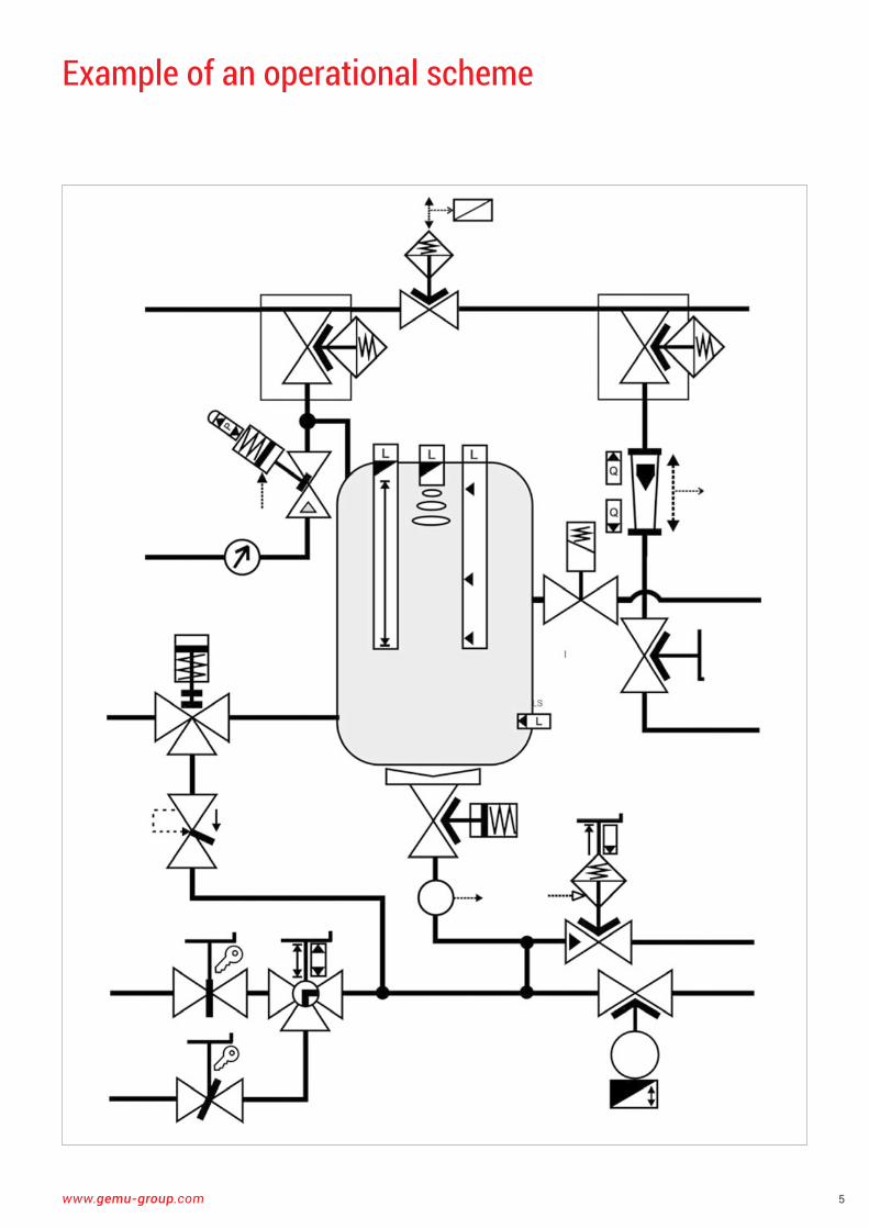
Example of an operational scheme
6
Piping system
Valve
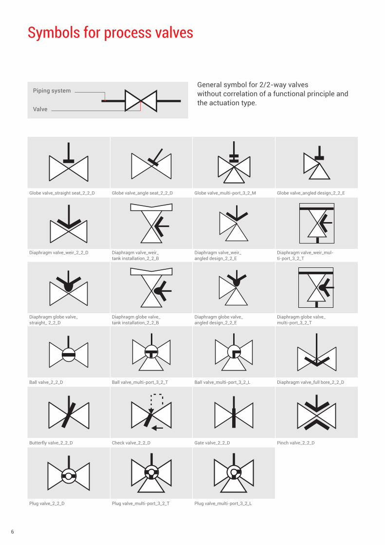
Symbols for process valves
General symbol for 2/2-way valves without correlation of a functional principle and the actuation type .
Globe valve_straight seat_2_2_D Globe valve_angle seat_2_2_D Globe valve_multi-port_3_2_M Globe valve_angled design_2_2_E
Diaphragm valve_weir_2_2_D Diaphragm valve_weir_ tank installation_2_2_B
Diaphragm valve_weir_ angled design_2_2_E
Diaphragm valve_weir_mul-ti-port_3_2_T
Diaphragm globe valve_ straight_ 2_2_D
Diaphragm globe valve_ tank installation_2_2_B
Diaphragm globe valve_ angled design_2_2_E
Diaphragm globe valve_ multi-port_3_2_T
Ball valve_2_2_D Ball valve_multi-port_3_2_T Ball valve_multi-port_3_2_L Diaphragm valve_full bore_2_2_D
Butterfly valve_2_2_D Check valve_2_2_D Gate valve_2_2_D Pinch valve_2_2_D
Plug valve_2_2_D Plug valve_multi-port_3_2_T Plug valve_multi-port_3_2_L
www.gemu-group.com 7
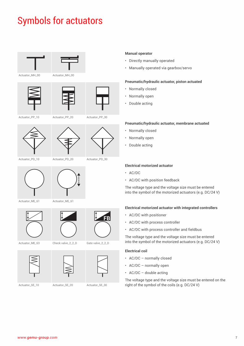
Symbols for actuators
Manual operator
• Directly manually operated
• Manually operated via gearbox/servo
Pneumatic/hydraulic actuator, piston actuated
• Normally closed
• Normally open
• Double acting
Pneumatic/hydraulic actuator, membrane actuated
• Normally closed
• Normally open
• Double acting
Electrical motorized actuator
• AC/DC
• AC/DC with position feedback
The voltage type and the voltage size must be entered into the symbol of the motorized actuators (e .g . DC/24 V)
Electrical motorized actuator with integrated controllers
• AC/DC with positioner
• AC/DC with process controller
• AC/DC with process controller and fieldbus
The voltage type and the voltage size must be entered into the symbol of the motorized actuators (e .g . DC/24 V)
Electrical coil
• AC/DC – normally closed
• AC/DC – normally open
• AC/DC – double acting
The voltage type and the voltage size must be entered on the right of the symbol of the coils (e .g . DC/24 V)
Actuator_MH_00 Actuator_MH_00
Actuator_PP_10 Actuator_PP_20 Actuator_PP_30
Actuator_PD_10 Actuator_PD_20 Actuator_PD_30
Actuator_ME_61 Actuator_ME_61
Actuator_ME_63 Check valve_2_2_D Gate valve_2_2_D
Actuator_SE_10 Actuator_SE_20 Actuator_SE_30
8
fd_gas fd_steam fd_liquid
Hydraulic Pneumatic
Lockable
stl_o stl_c stl_oc
EPI_oc EPI_o EPI_c
EPIO_oc EPIO_o EPIO_c
AirFB
AirFB
CBA FB FBA
P
P
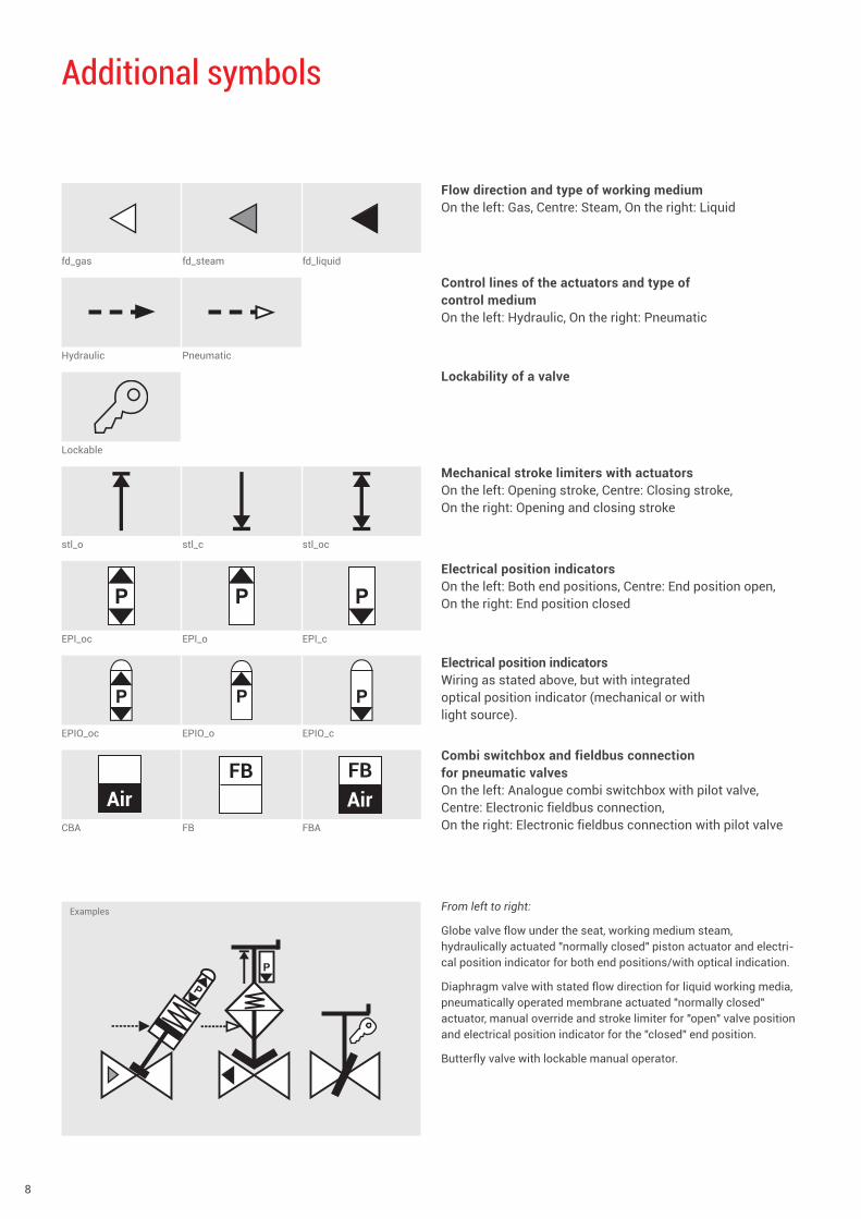
Additional symbols
Control lines of the actuators and type of control mediumOn the left: Hydraulic, On the right: Pneumatic
Flow direction and type of working mediumOn the left: Gas, Centre: Steam, On the right: Liquid
Lockability of a valve
Mechanical stroke limiters with actuatorsOn the left: Opening stroke, Centre: Closing stroke, On the right: Opening and closing stroke
Electrical position indicatorsOn the left: Both end positions, Centre: End position open, On the right: End position closed
Combi switchbox and fieldbus connection for pneumatic valvesOn the left: Analogue combi switchbox with pilot valve, Centre: Electronic fieldbus connection, On the right: Electronic fieldbus connection with pilot valve
From left to right:
Globe valve flow under the seat, working medium steam, hydraulically actuated "normally closed" piston actuator and electri-cal position indicator for both end positions/with optical indication .
Diaphragm valve with stated flow direction for liquid working media, pneumatically operated membrane actuated "normally closed" actuator, manual override and stroke limiter for "open" valve position and electrical position indicator for the "closed" end position .
Butterfly valve with lockable manual operator .
Electrical position indicators Wiring as stated above, but with integrated optical position indicator (mechanical or with light source) .
Examples
www.gemu-group.com 9
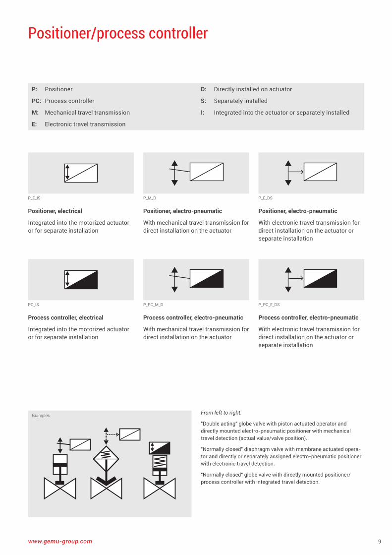
P_E_IS
PC_IS
P_M_D
P_PC_M_D
P_E_DS
P_PC_E_DS
Positioner/process controller
P: Positioner
PC: Process controller
M: Mechanical travel transmission
E: Electronic travel transmission
D: Directly installed on actuator
S: Separately installed
I: Integrated into the actuator or separately installed
From left to right:
"Double acting" globe valve with piston actuated operator and directly mounted electro-pneumatic positioner with mechanical travel detection (actual value/valve position) .
"Normally closed" diaphragm valve with membrane actuated opera-tor and directly or separately assigned electro-pneumatic positioner with electronic travel detection .
"Normally closed" globe valve with directly mounted positioner/process controller with integrated travel detection .
Examples
Positioner, electrical
Integrated into the motorized actuator or for separate installation
Process controller, electrical
Integrated into the motorized actuator or for separate installation
Positioner, electro-pneumatic
With mechanical travel transmission for direct installation on the actuator
Process controller, electro-pneumatic
With mechanical travel transmission for direct installation on the actuator
Positioner, electro-pneumatic
With electronic travel transmission for direct installation on the actuator or separate installation
Process controller, electro-pneumatic
With electronic travel transmission for direct installation on the actuator or separate installation
10
Examples
P
AirFB P
PP
DC
24
FB
DC24
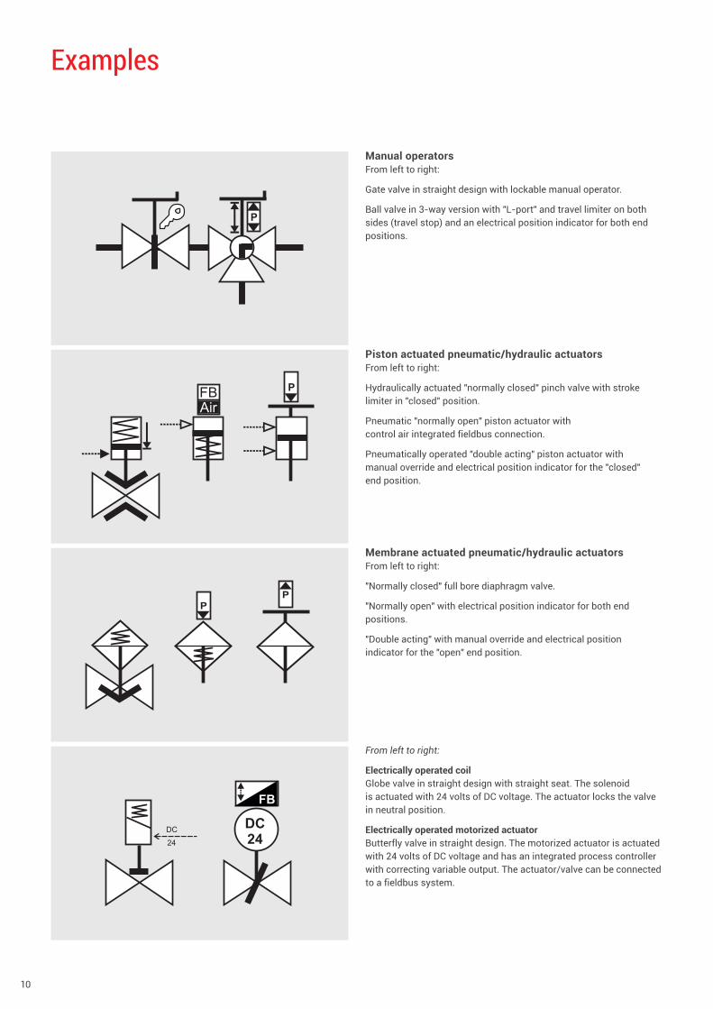
Manual operatorsFrom left to right:
Gate valve in straight design with lockable manual operator .
Ball valve in 3-way version with "L-port" and travel limiter on both sides (travel stop) and an electrical position indicator for both end positions .
Piston actuated pneumatic/hydraulic actuatorsFrom left to right:
Hydraulically actuated "normally closed" pinch valve with stroke limiter in "closed" position .
Pneumatic "normally open" piston actuator with control air integrated fieldbus connection .
Pneumatically operated "double acting" piston actuator with manual override and electrical position indicator for the "closed" end position .
Membrane actuated pneumatic/hydraulic actuatorsFrom left to right:
"Normally closed" full bore diaphragm valve .
"Normally open" with electrical position indicator for both end positions .
"Double acting" with manual override and electrical position indicator for the "open" end position .
From left to right:
Electrically operated coil Globe valve in straight design with straight seat . The solenoid is actuated with 24 volts of DC voltage . The actuator locks the valve in neutral position .
Electrically operated motorized actuator Butterfly valve in straight design . The motorized actuator is actuated with 24 volts of DC voltage and has an integrated process controller with correcting variable output . The actuator/valve can be connected to a fieldbus system .
www.gemu-group.com 11
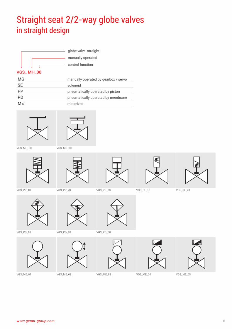
VGS_ MH_00MG manually operated by gearbox / servo
SE solenoid
PP pneumatically operated by piston
PD pneumatically operated by membrane
ME motorized
globe valve, straight
manually operated
control function
VGS_MH_00 VGS_MG_00
VGS_PP_10 VGS_PP_20 VGS_PP_30 VGS_SE_10 VGS_SE_20
VGS_PD_10 VGS_PD_20 VGS_PD_30
FB FB FB
VGS_ME_61 VGS_ME_62 VGS_ME_63 VGS_ME_64 VGS_ME_65
Straight seat 2/2-way globe valves in straight design
12
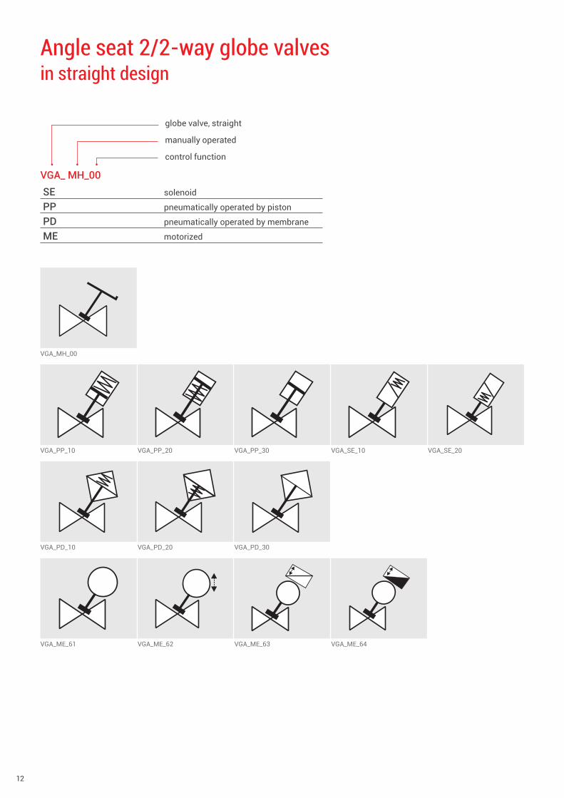
VGA_ MH_00SE solenoid
PP pneumatically operated by piston
PD pneumatically operated by membrane
ME motorized
globe valve, straight
manually operated
control function
VGA_MH_00
VGA_PP_10 VGA_PP_20 VGA_PP_30 VGA_SE_10 VGA_SE_20
VGA_PD_10 VGA_PD_20 VGA_PD_30
VGA_ME_61 VGA_ME_62 VGA_ME_63 VGA_ME_64
Angle seat 2/2-way globe valves in straight design
www.gemu-group.com 13
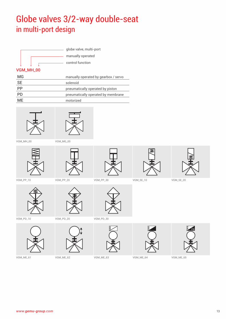
Globe valves 3/2-way double-seat in multi-port design
VGM_MH_00MG manually operated by gearbox / servo
SE solenoid
PP pneumatically operated by piston
PD pneumatically operated by membrane
ME motorized
globe valve, multi-port
manually operated
control function
VGM_MH_00 VGM_MG_00
VGM_PP_10 VGM_PP_20 VGM_PP_30 VGM_SE_10 VGM_SE_20
VGM_PD_10 VGM_PD_20 VGM_PD_30
VGM_ME_61 VGM_ME_62 VGM_ME_63 VGM_ME_64 VGM_ME_65
14
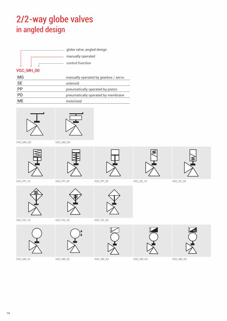
2/2-way globe valves in angled design
VGC_MH_00MG manually operated by gearbox / servo
SE solenoid
PP pneumatically operated by piston
PD pneumatically operated by membrane
ME motorized
globe valve, angled design
manually operated
control function
VGC_MH_00 VGC_MG_00
VGC_PP_10 VGC_PP_20 VGC_PP_30 VGC_SE_10 VGC_SE_20
VGC_PD_10 VGC_PD_20 VGC_PD_30
VGC_ME_61 VGC_ME_62 VGC_ME_63 VGC_ME_64 VGC_ME_65
www.gemu-group.com 15
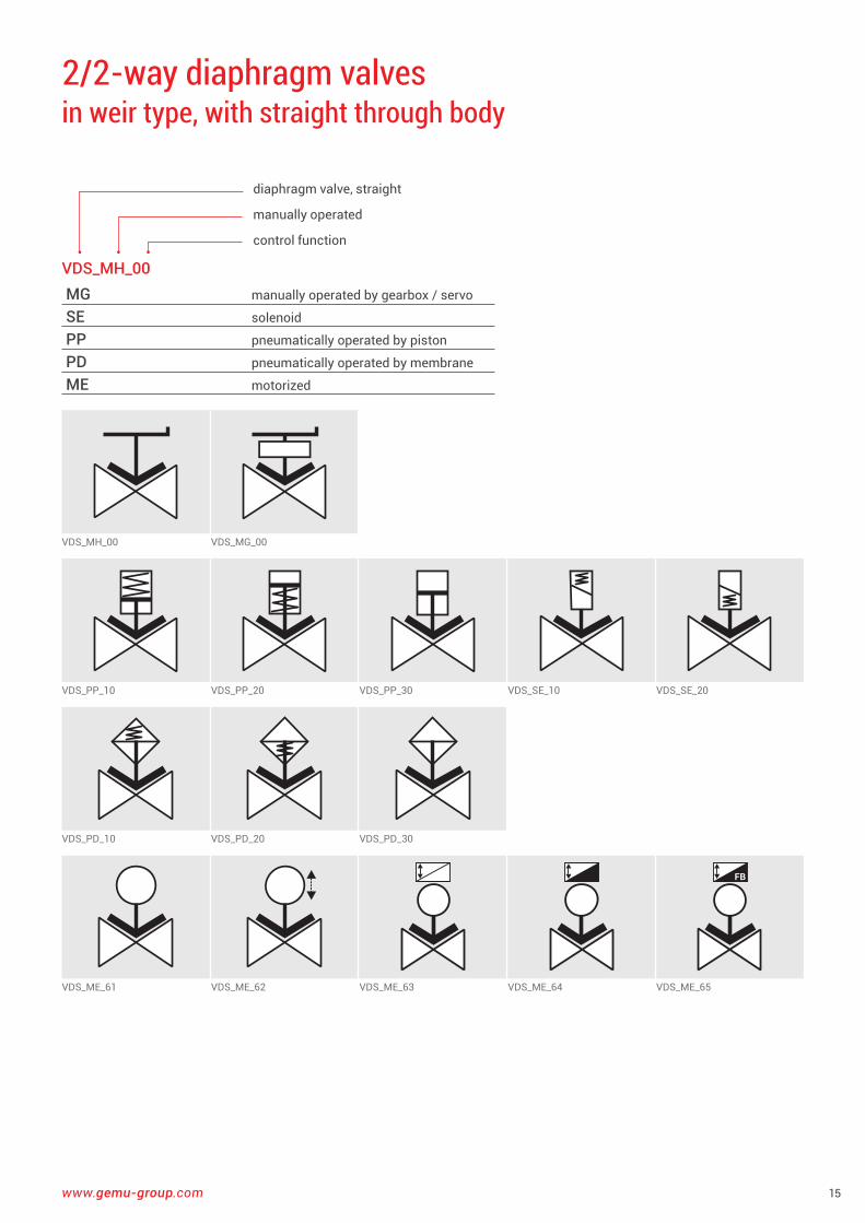
VDS_MH_00 VDS_MG_00
VDS_PP_10 VDS_PP_20 VDS_PP_30 VDS_SE_10 VDS_SE_20
VDS_PD_10 VDS_PD_20 VDS_PD_30
FB
VDS_ME_61 VDS_ME_62 VDS_ME_63 VDS_ME_64 VDS_ME_65
2/2-way diaphragm valves in weir type, with straight through body
VDS_MH_00MG manually operated by gearbox / servo
SE solenoid
PP pneumatically operated by piston
PD pneumatically operated by membrane
ME motorized
diaphragm valve, straight
manually operated
control function
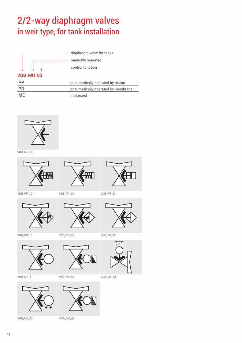
16
VDB_MH_00
VDB_PP_10 VDB_PP_20 VDB_PP_30
VDB_PD_10 VDB_PD_20 VDB_PD_30
VDB_ME_61 VDB_ME_64 VDB_ME_63
FB
VDB_ME_62 VDB_ME_65
2/2-way diaphragm valves in weir type, for tank installation
VDB_MH_00PP pneumatically operated by piston
PD pneumatically operated by membrane
ME motorized
diaphragm valve for tanks
manually operated
control function
www.gemu-group.com 17
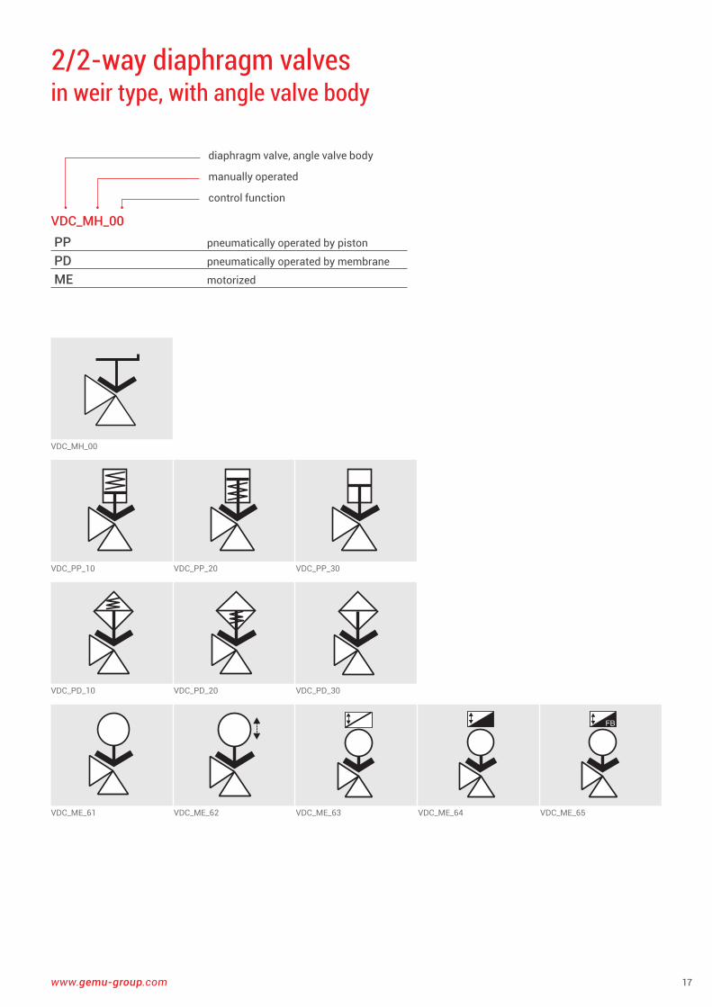
2/2-way diaphragm valves in weir type, with angle valve body
VDC_MH_00PP pneumatically operated by piston
PD pneumatically operated by membrane
ME motorized
diaphragm valve, angle valve body
manually operated
control function
VDC_MH_00
VDC_PP_10 VDC_PP_20 VDC_PP_30
VDC_PD_10 VDC_PD_20 VDC_PD_30
VDC_ME_61 VDC_ME_62 VDC_ME_63 VDC_ME_64 VDC_ME_65
18
VDT_MH_00
VDT_PP_10 VDT_PP_20 VDT_PP_30
VDT_PD_10 VDT_PD_20 VDT_PD_30
FB
VDT_ME_61 VDT_ME_62 VDT_ME_63
FB
VDT_ME_64 VDT_ME_65
3/2-way diaphragm valves in weir type, with T body
VDT_MH_00PP pneumatically operated by piston
PD pneumatically operated by membrane
ME motorized
diaphragm valve, T-design
manually operated
control function
www.gemu-group.com 19
VPDS_MH_00 VPDS_MG_00
VPDS_PP_10 VPDS_PP_20 VPDS_PP_30 VPDS_SE_10 VPDS_SE_20
VPDS_PD_10 VPDS_PD_20 VPDS_PD_30
FB
VPDS_ME_61 VPDS_ME_62 VPDS_ME_63 VPDS_ME_64 VPDS_ME_65
2/2-way diaphragm globe valves with straight through body
VPDS_MH_00MG manually operated by gearbox / servo
SE solenoid
PP pneumatically operated by piston
PD pneumatically operated by membrane
ME motorized
diaphragm globe valve, straight
manually operated
control function
20
2/2-way diaphragm globe valves in angled design
VPDC_MH_00PP pneumatically operated by piston
SE solenoid
PD pneumatically operated by membrane
ME motorized
diaphragm globe valve, angled design
manually operated
control function
VPDC_MH_00
VPDC_PP_10 VPDC_PP_20 VPDC_PP_30 VPDC_SE_10 VPDC_SE_20
VPDC_PD_10 VPDC_PD_20 VPDC_PD_30
VPDC_ME_61 VPDC_ME_62 VPDC_ME_63 VPDC_ME_64 VPDC_ME_65
www.gemu-group.com 21
2/2-way diaphragm globe valves for tank installation
VPDB_MH_00PP pneumatically operated by piston
SE solenoid
PD pneumatically operated by membrane
ME motorized
diaphragm globe valve for tanks
manually operated
control function
VPDB_MH_00
VPDB_PP_10 VPDB_PP_20 VPDB_PP_30 VPDB_SE_10 VPDB_SE_20
VPDB_PD_10 VPDB_PD_20 VPDB_PD_30
VPDB_ME_61 VPDB_ME_64 VPDB_ME_63
FB
VPDB_ME_62 VPDB_ME_65
22
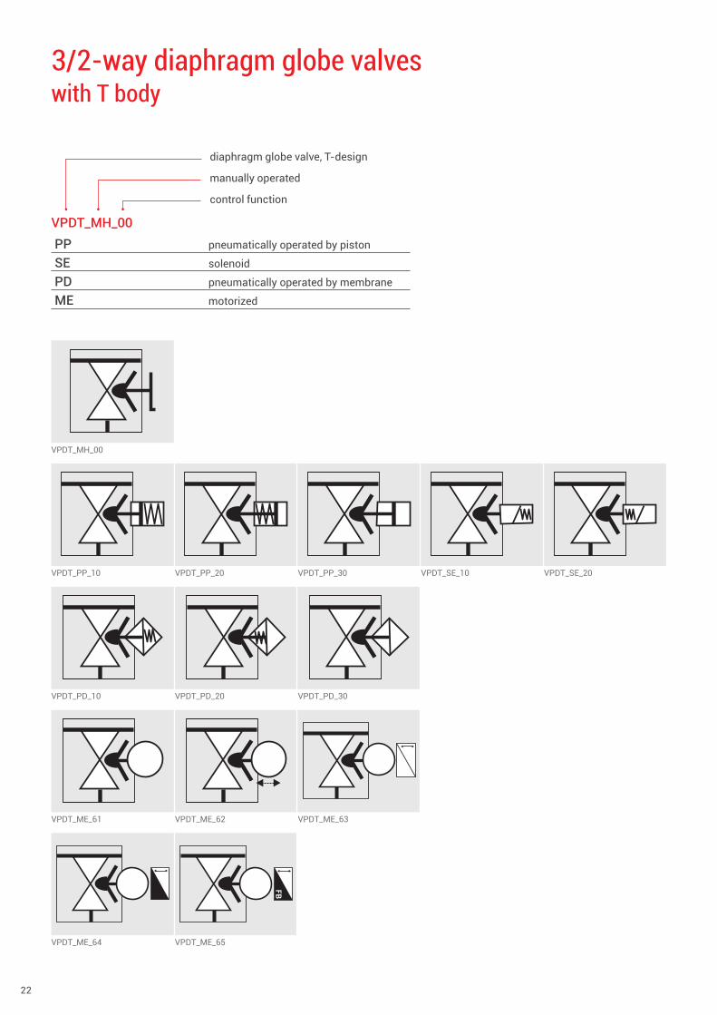
VPDT_MH_00
VPDT_PP_10 VPDT_PP_20 VPDT_PP_30 VPDT_SE_10 VPDT_SE_20
VPDT_PD_10 VPDT_PD_20 VPDT_PD_30
VPDT_ME_61 VPDT_ME_62 VPDT_ME_63
FB
VPDT_ME_64 VPDT_ME_65
3/2-way diaphragm globe valves with T body
VPDT_MH_00PP pneumatically operated by piston
SE solenoid
PD pneumatically operated by membrane
ME motorized
diaphragm globe valve, T-design
manually operated
control function
www.gemu-group.com 23
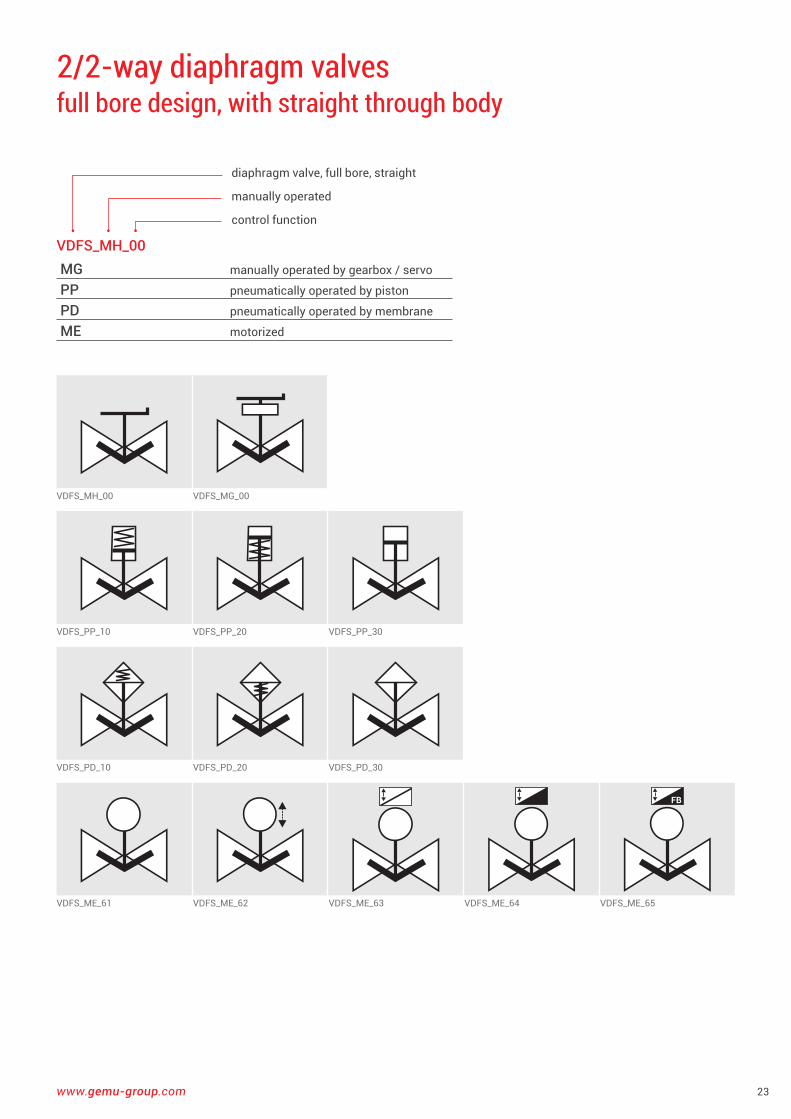
VDFS_MH_00 VDFS_MG_00
VDFS_PP_10 VDFS_PP_20 VDFS_PP_30
VDFS_PD_10 VDFS_PD_20 VDFS_PD_30
FB
VDFS_ME_61 VDFS_ME_62 VDFS_ME_63 VDFS_ME_64 VDFS_ME_65
2/2-way diaphragm valves full bore design, with straight through body
VDFS_MH_00MG manually operated by gearbox / servo
PP pneumatically operated by piston
PD pneumatically operated by membrane
ME motorized
diaphragm valve, full bore, straight
manually operated
control function
24
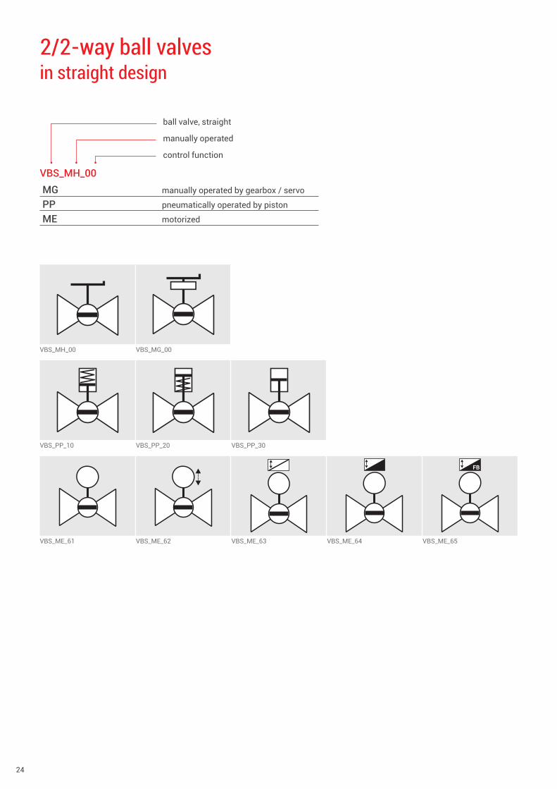
VBS_MH_00 VBS_MG_00
VBS_PP_10 VBS_PP_20 VBS_PP_30
FB
VBS_ME_61 VBS_ME_62 VBS_ME_63 VBS_ME_64 VBS_ME_65
2/2-way ball valves in straight design
VBS_MH_00MG manually operated by gearbox / servo
PP pneumatically operated by piston
ME motorized
ball valve, straight
manually operated
control function

www.gemu-group.com 25
VBM_T_MH_00 VBM_T_MG_00
VBM_T_PP_10 VBM_T_PP_20 VBM_T_PP_30
FB
VBM_T_ME_61 VBM_T_ME_62 VBM_T_ME_63 VBM_T_ME_64 VBM_T_ME_65
3/2-way ball valves with T-port, in multi-port design
VBM_T_MH_00MG manually operated by gearbox / servo
PP pneumatically operated by piston
ME motorized
ball valve, multi-port
T-port
manually operated
control function

26
VBM_L_MH_00 VBM_L_MG_00
VBM_L_PP_10 VBM_L_PP_20 VBM_L_PP_30
FB
VBM_L_ME_61 VBM_L_ME_62 VBM_L_ME_63 VBM_L_ME_64 VBM_L_ME_65
3/2-way ball valves with L-port, in multi-port design
VBM_L_MH_00MG manually operated by gearbox / servo
PP pneumatically operated by piston
ME motorized
ball valve, multi-port
L-port
manually operated
control function
www.gemu-group.com 27
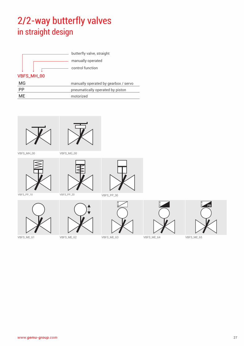
VBFS_MH_00 VBFS_MG_00
VBFS_PP_10 VBFS_PP_20 VBFS_PP_30
FB
VBFS_ME_61 VBFS_ME_62 VBFS_ME_63 VBFS_ME_64 VBFS_ME_65
2/2-way butterfly valves in straight design
VBFS_MH_00MG manually operated by gearbox / servo
PP pneumatically operated by piston
ME motorized
butterfly valve, straight
manually operated
control function
28
VBFS_PO
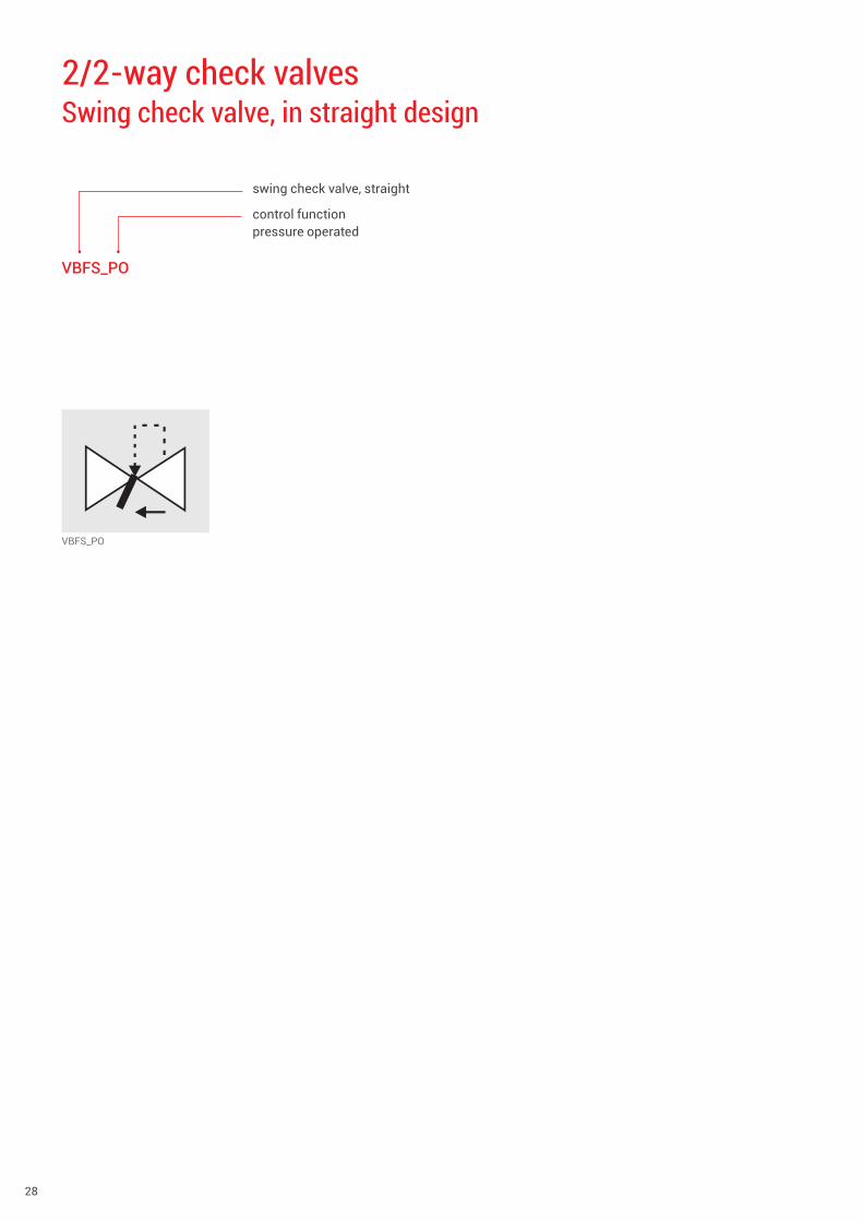
2/2-way check valves Swing check valve, in straight design
VBFS_PO
swing check valve, straight
control function pressure operated
www.gemu-group.com 29
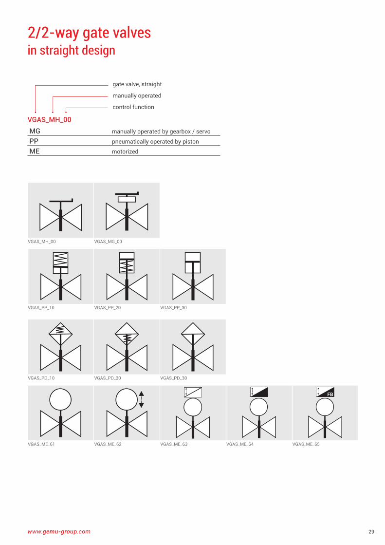
VGAS_MH_00 VGAS_MG_00
VGAS_PP_10 VGAS_PP_20 VGAS_PP_30
VGAS_PD_10 VGAS_PD_20 VGAS_PD_30
FB
VGAS_ME_61 VGAS_ME_62 VGAS_ME_63 VGAS_ME_64 VGAS_ME_65
2/2-way gate valves in straight design
VGAS_MH_00MG manually operated by gearbox / servo
PP pneumatically operated by piston
ME motorized
gate valve, straight
manually operated
control function
30
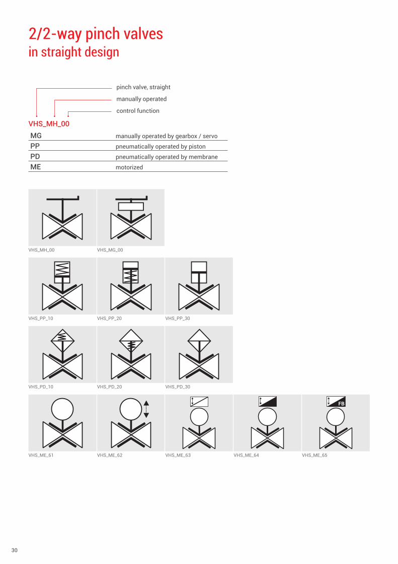
2/2-way pinch valves in straight design
VHS_MH_00MG manually operated by gearbox / servo
PP pneumatically operated by piston
PD pneumatically operated by membrane
ME motorized
pinch valve, straight
manually operated
control function
VHS_MH_00 VHS_MG_00
VHS_PP_10 VHS_PP_20 VHS_PP_30
VHS_PD_10 VHS_PD_20 VHS_PD_30
FB
VHS_ME_61 VHS_ME_62 VHS_ME_63 VHS_ME_64 VHS_ME_65

www.gemu-group.com 31
2/2-way plug valves in straight design
VPS_MH_00MG manually operated by gearbox / servo
PP pneumatically operated by piston
ME motorized
plug valve, straight
manually operated
control function
VPS_MH_00 VPS_MG_00
VPS_PP_10 VPS_PP_20 VPS_PP_30
FB
VPS_ME_61 VPS_ME_62 VPS_ME_63 VPS_ME_64 VPS_ME_65
32
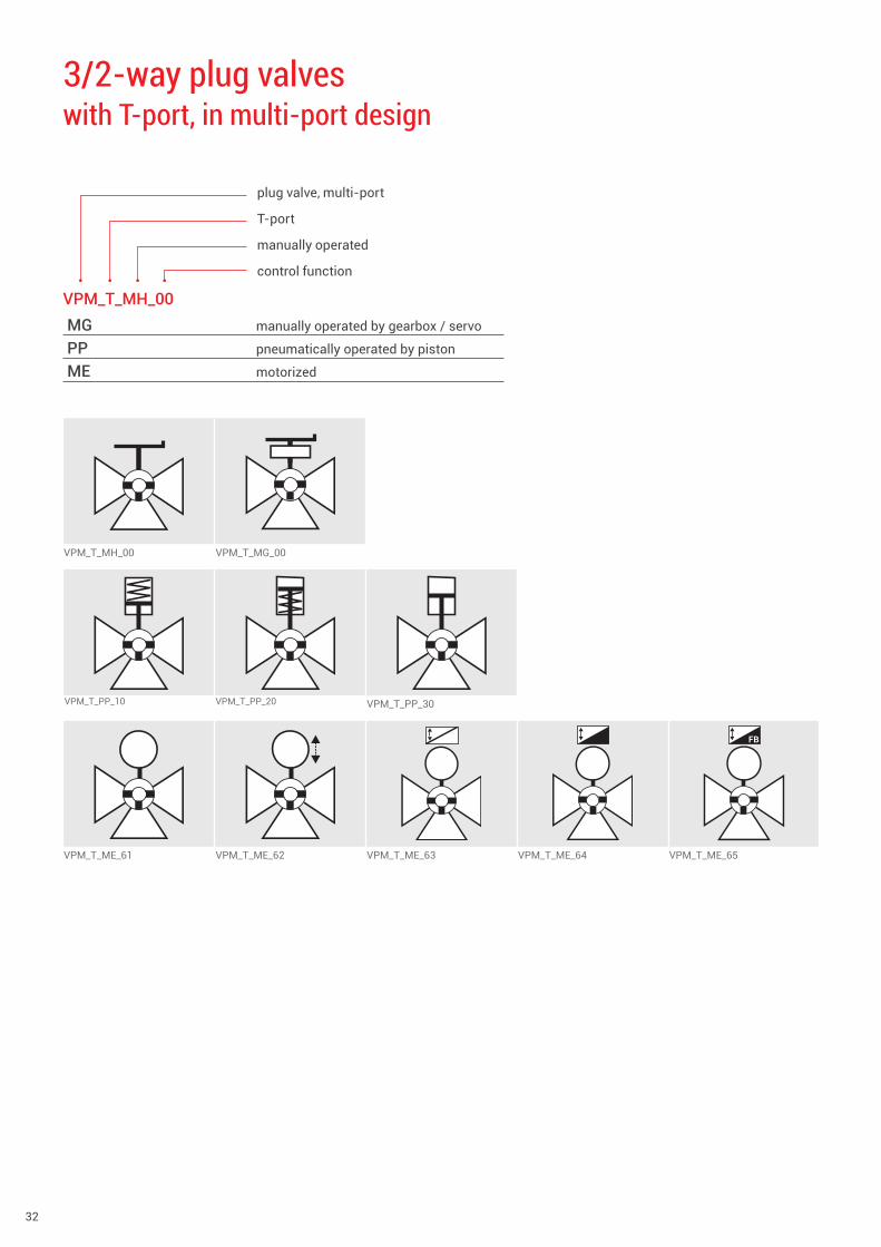
3/2-way plug valves with T-port, in multi-port design
VPM_T_MH_00 VPM_T_MG_00
VPM_T_PP_10 VPM_T_PP_20 VPM_T_PP_30
FB
VPM_T_ME_61 VPM_T_ME_62 VPM_T_ME_63 VPM_T_ME_64 VPM_T_ME_65
VPM_T_MH_00MG manually operated by gearbox / servo
PP pneumatically operated by piston
ME motorized
plug valve, multi-port
T-port
manually operated
control function
www.gemu-group.com 33
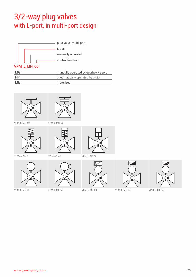
3/2-way plug valves with L-port, in multi-port design
VPM_L_MH_00 VPM_L_MG_00
VPM_L_PP_10 VPM_L_PP_20 VPM_L_PP_30
FB
VPM_L_ME_61 VPM_L_ME_62 VPM_L_ME_63 VPM_L_ME_64 VPM_L_ME_65
VPM_L_MH_00MG manually operated by gearbox / servo
PP pneumatically operated by piston
ME motorized
plug valve, multi-port
L-port
manually operated
control function
34
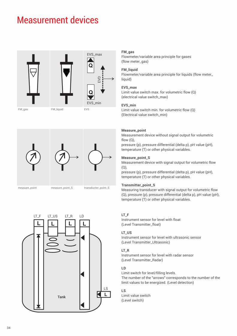
Measurement devices
FM_gasFlowmeter/variable area principle for gases (flow meter_gas)
FM_liquidFlowmeter/variable area principle for liquids (flow meter_liquid)
EVS_maxLimit value switch max . for volumetric flow (Q) (electrical value switch_max)
EVS_minLimit value switch min . for volumetric flow (Q) (Electrical value switch_min)
Measure_pointMeasurement device without signal output for volumetric flow (Q), pressure (p), pressure differential (delta p), pH value (pH), temperature (T) or other physical variables .
Measure_point_SMeasurement device with signal output for volumetric flow (Q), pressure (p), pressure differential (delta p), pH value (pH), temperature (T) or other physical variables .
Transmitter_point_SMeasuring transducer with signal output for volumetric flow (Q), pressure (p), pressure differential (delta p), pH value (pH), temperature (T) or other physical variables .
LT_FInstrument sensor for level with float (Level Transmitter_float)
LT_USInstrument sensor for level with ultrasonic sensor (Level Transmitter_Ultrasonic)
LT_RInstrument sensor for level with radar sensor (Level Transmitter_Radar)
LDLimit switch for level/filling levels . The number of the "arrows" corresponds to the number of the limit values to be energized . (Level detection)
LSLimit value switch (Level switch)
measure_point measure_point_S transducter_point_S
Q
FM_gas FM_liquid EVS
Q
EVS_max
EVS_minEV
D
LT_F LT_US LT_R LD
LS
Tank
www.gemu-group.com 35
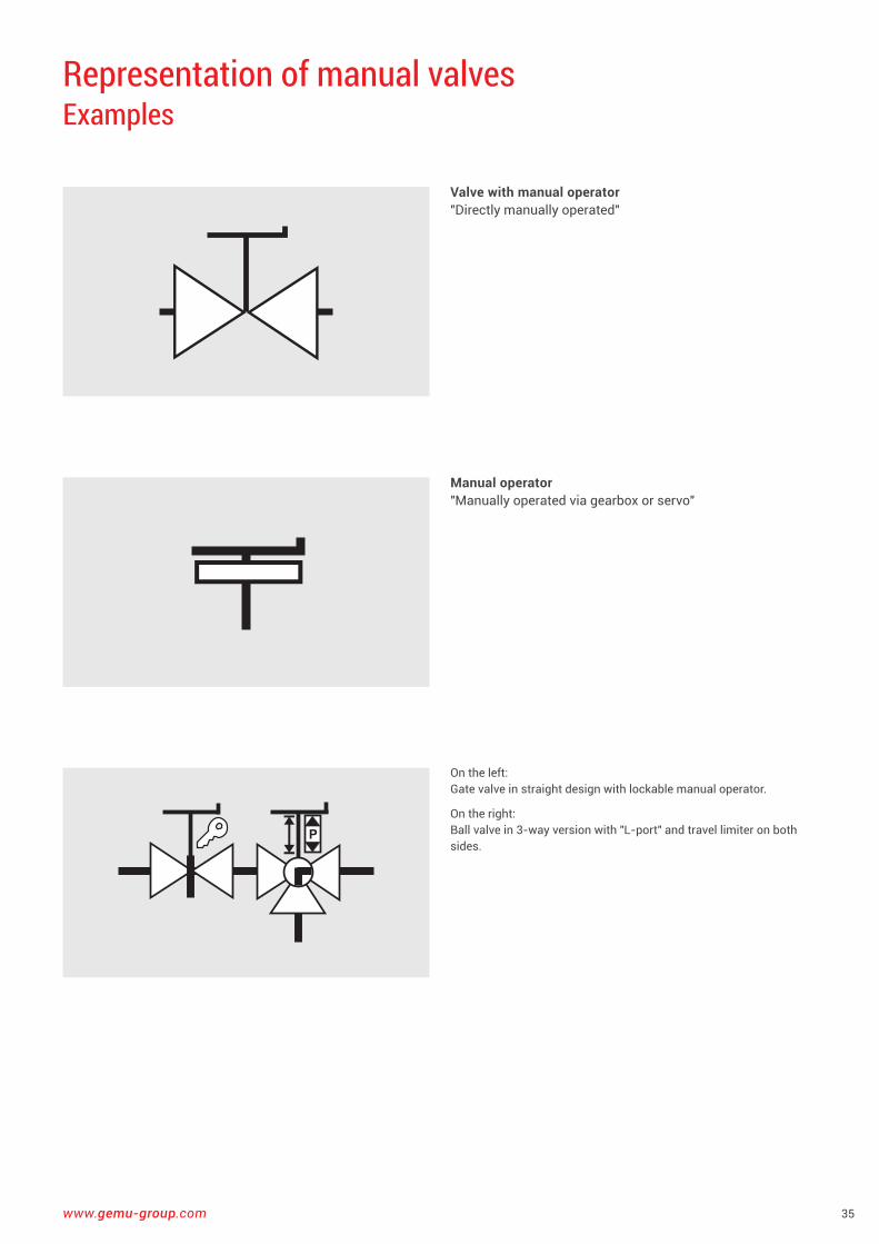
Representation of manual valves Examples
Valve with manual operator"Directly manually operated"
Manual operator"Manually operated via gearbox or servo"
P
On the left: Gate valve in straight design with lockable manual operator .
On the right: Ball valve in 3-way version with "L-port" and travel limiter on both sides .
36
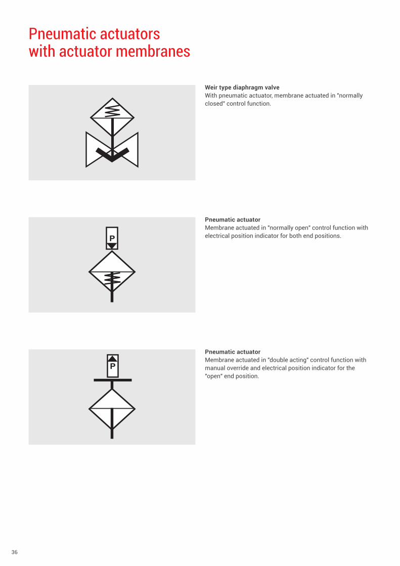
Pneumatic actuatorswith actuator membranes
Weir type diaphragm valve With pneumatic actuator, membrane actuated in "normally closed" control function .
Pneumatic actuatorMembrane actuated in "normally open" control function with electrical position indicator for both end positions .
Pneumatic actuatorMembrane actuated in "double acting" control function with manual override and electrical position indicator for the "open" end position .
P
P
www.gemu-group.com 37
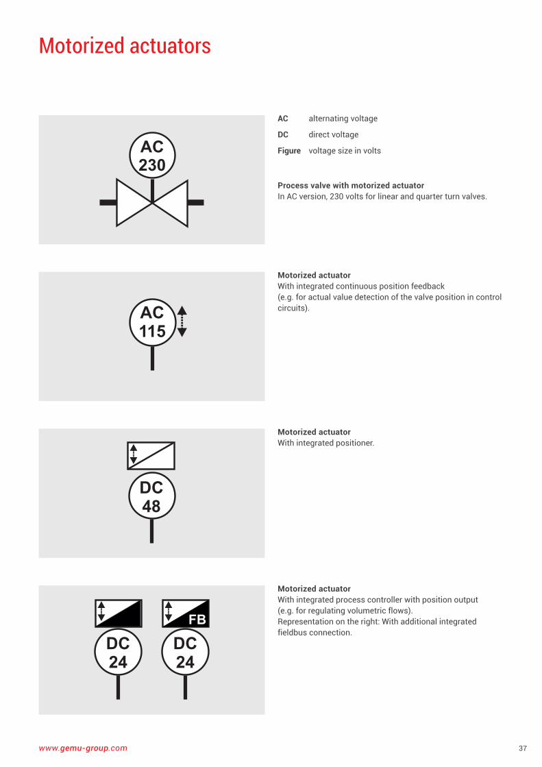
Motorized actuators
AC alternating voltage
DC direct voltage
Figure voltage size in volts
Process valve with motorized actuatorIn AC version, 230 volts for linear and quarter turn valves .
Motorized actuatorWith integrated continuous position feedback (e .g . for actual value detection of the valve position in control circuits) .
Motorized actuator With integrated positioner .
Motorized actuatorWith integrated process controller with position output (e .g . for regulating volumetric flows) . Representation on the right: With additional integrated fieldbus connection .
AC230
AC115
DC48
DC24
DC24
FB
38
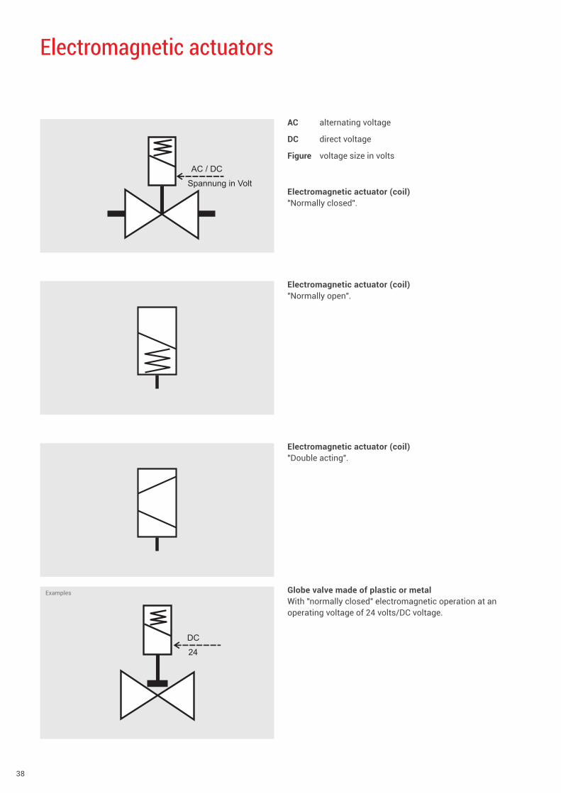
Electromagnetic actuators
AC alternating voltage
DC direct voltage
Figure voltage size in volts
Electromagnetic actuator (coil)"Normally closed" .
Electromagnetic actuator (coil)"Normally open" .
Electromagnetic actuator (coil)"Double acting" .
AC / DC
Spannung in Volt
DC
24
Globe valve made of plastic or metalWith "normally closed" electromagnetic operation at an operating voltage of 24 volts/DC voltage .
Examples
www.gemu-group.com 39
The use of the valve symbols in Technical Communication and its procurement
Proposal system and procurement easy and preciseAs experience shows, there are many classic error sources in technical procurement of goods .
The problems frequently begin with the fact that a technician must present the product required by them such that the Purchasing department unequivocally understands which attributes and features the product should have . A quotation request is now formulated here, which can be totally different in type and scope depending on the personal method of the purchasers and the in-house procedure . In the worst case scenario, the Purchasing department does not precisely understand which technical factors the product to be procured depends on and only pays attention to a price advantage .
After the respectively requested providers have received the quotation request, they must first extensively analyze the contents and integrate them into each of their individual understandings and proposal systems . Now the providers formulate their respective offer in their own personal way and according to the specifications of their company .
The requesting Purchasing department now receives dif-ferent offers from the providers, which it must again "re-translate" into its own language and make them comparable with each other . It is clearly apparent why, despite the latest
auxiliary materials, there can be all kinds of error sources – and this is even before the procedure continues with the formulation of the real order .
To avoid this, standardized procurement schemes have been developed by a huge variety of institutions and organizations . But only too often has the error been made here that all types of goods or at least all product versions of a goods group should be covered with a single "universal form" . You therefore encounter quotation forms with up to four pages per requested valve .
When procuring valves for process engineering and tank and pipeline construction, such a situation can be easily dodged . The use of the symbols shown in this manual in combination with the entry tables shown allows a simpler and safer valve request . Based on similar technical valve attributes to be considered, the entry sheets of globe and diaphragm valves and of ball and plug valves can each be summarized . For all further functional principles, independent entry sheets must be created .
40
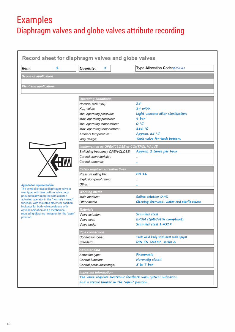
Record sheet for diaphragm valves and globe valves
Item: 1 Quantity: 1 Type Allocation Code:�0000
Scope of application
Plant and application
Operating conditionsNominal size (DN): 25K VS value: 14 m³/hMin. operating pressure: Light vacuum after sterilizationMax. operating pressure: 4 barMin. operating temperature: 0 °CMax. operating temperature: 130 °CAmbient temperature: Approx. 25 °CWay design: Tank valve for tank bottom
Implemented as OPEN/CLOSE or CONTROL VALVESwitching frequency OPEN/CLOSE: Approx. 2 times per hourControl characteristic : _Control amounts: _
Safety requirements/directivesPressure rating PN: PN 16Explosion-proof rating: _Other: _
Working mediaMain medium: Saline solution 0.9%Other media Cleaning chemicals, water and sterile steam
MaterialsValve actuator: Stainless steelValve seal: EPDM (GMP/FDA compliant)Valve body: Stainless steel 1.4539
Pipe connectionConnection type: Tank weld body with butt weld spigotStandard: DIN EN 10357, series A
Actuator dataActuation type: PneumaticControl function: Normally closedControl pressure/voltage: 5 to 7 bar
Important informationThe valve requires electronic feedback with optical indication and a stroke limiter in the "open" position.
Examples Diaphragm valves and globe valves attribute recording
Agenda for representation The symbol shows a diaphragm valve in weir type, with tank bottom valve body, pneumatically operated with a piston actuated operator in the "normally closed" function; with mounted electrical position indicator for both valve positions with optical indication and a mechanical regulating distance limitation for the "open" position .
www.gemu-group.com 41
Record sheet for diaphragm valves and globe valves
Item: 1 Quantity: 1 Type Allocation Code: 0000 0
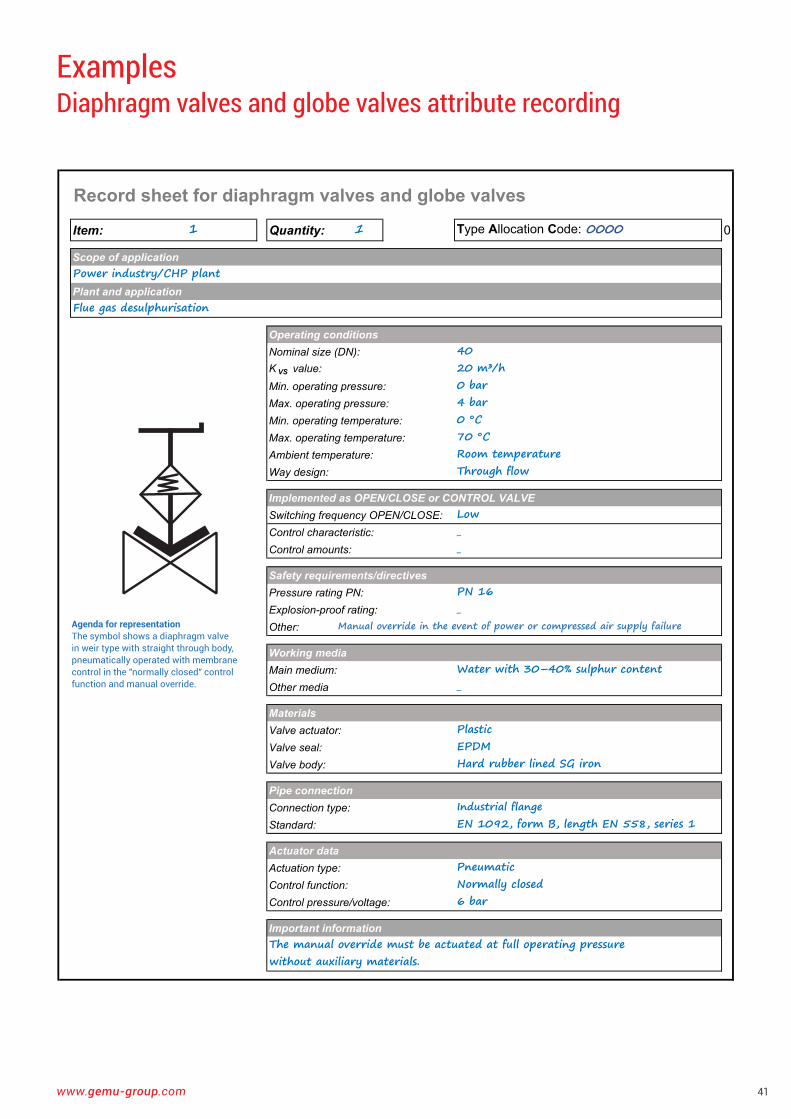
Scope of applicationPower industry/CHP plantPlant and applicationFlue gas desulphurisation
Operating conditionsNominal size (DN): 40K VS value: 20 m³/hMin. operating pressure: 0 barMax. operating pressure: 4 barMin. operating temperature: 0 °CMax. operating temperature: 70 °CAmbient temperature: Room temperatureWay design: Through flow
Implemented as OPEN/CLOSE or CONTROL VALVESwitching frequency OPEN/CLOSE: LowControl characteristic: _Control amounts: _
Safety requirements/directivesPressure rating PN: PN 16Explosion-proof rating: _Other: Manual override in the event of power or compressed air supply failure
Working mediaMain medium: Water with 30–40% sulphur contentOther media _
MaterialsValve actuator: PlasticValve seal: EPDMValve body: Hard rubber lined SG iron
Pipe connectionConnection type: Industrial flangeStandard: EN 1092, form B, length EN 558, series 1
Actuator dataActuation type: PneumaticControl function: Normally closedControl pressure/voltage: 6 bar
Important informationThe manual override must be actuated at full operating pressure without auxiliary materials.
Examples Diaphragm valves and globe valves attribute recording
Agenda for representation The symbol shows a diaphragm valve in weir type with straight through body, pneumatically operated with membrane control in the "normally closed" control function and manual override .
42
Record sheet for diaphragm valves and globe valves
Item: 1 Quantity: 1 Type Allocation Code: 0000 0
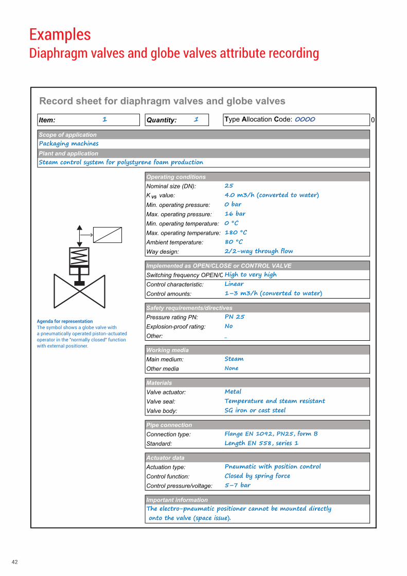
Scope of applicationPackaging machinesPlant and applicationSteam control system for polystyrene foam production
Operating conditionsNominal size (DN): 25K VS value: 4.0 m3/h (converted to water)Min. operating pressure: 0 barMax. operating pressure: 16 barMin. operating temperature: 0 °CMax. operating temperature: 180 °CAmbient temperature: 80 °CWay design: 2/2-way through flow
Implemented as OPEN/CLOSE or CONTROL VALVESwitching frequency OPEN/C High to very highControl characteristic: LinearControl amounts: 1–3 m3/h (converted to water)
Safety requirements/directivesPressure rating PN: PN 25Explosion-proof rating: NoOther: _
Working mediaMain medium: SteamOther media None
MaterialsValve actuator: MetalValve seal: Temperature and steam resistantValve body: SG iron or cast steel
Pipe connectionConnection type: Flange EN 1092, PN25, form BStandard: Length EN 558, series 1
Actuator dataActuation type: Pneumatic with position controlControl function: Closed by spring forceControl pressure/voltage: 5–7 bar
Important informationThe electro-pneumatic positioner cannot be mounted directly onto the valve (space issue).
Examples Diaphragm valves and globe valves attribute recording
Agenda for representation The symbol shows a globe valve with a pneumatically operated piston-actuated operator in the "normally closed" function with external positioner .
www.gemu-group.com 43
Record sheet for diaphragm valves and globe valves
Item: 1 Quantity: 1 Type Allocation Code: 0000 0
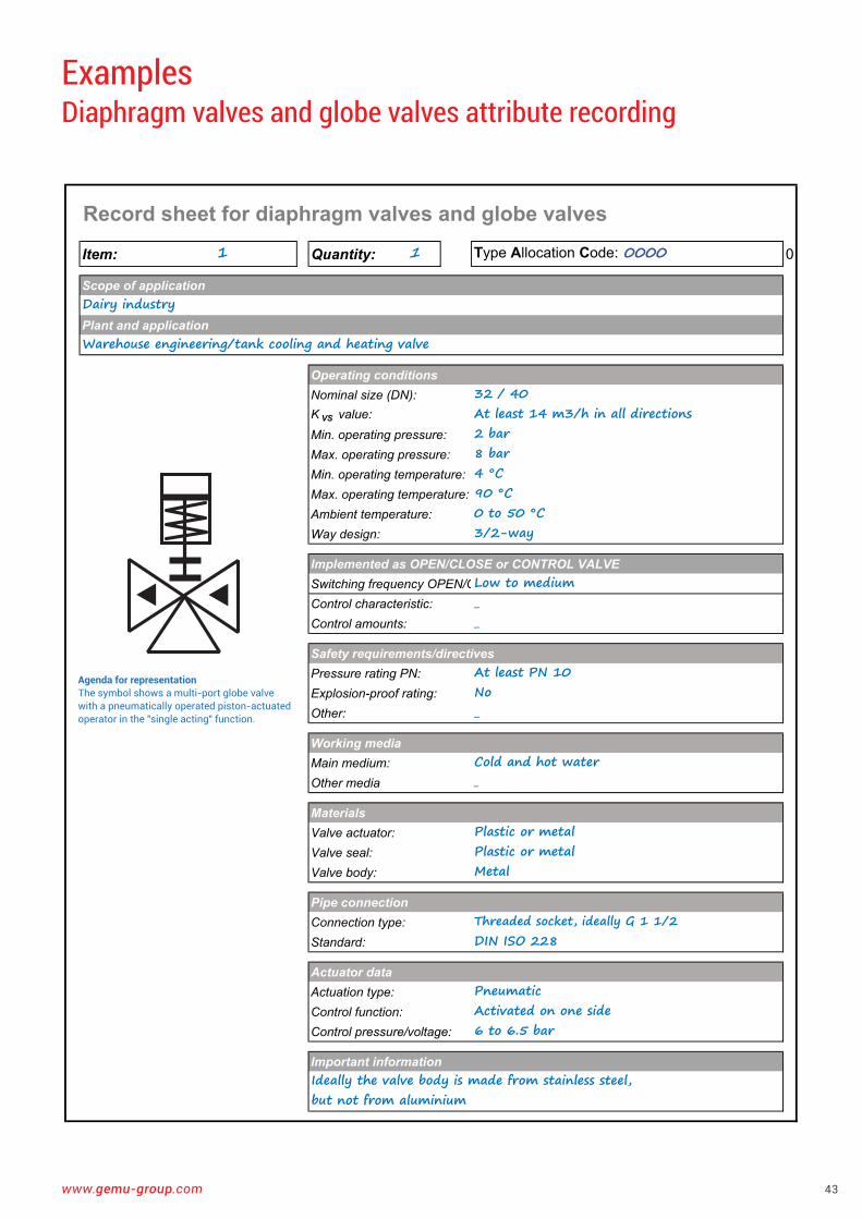
Scope of applicationDairy industryPlant and applicationWarehouse engineering/tank cooling and heating valve
Operating conditionsNominal size (DN): 32 / 40K VS value: At least 14 m3/h in all directionsMin. operating pressure: 2 barMax. operating pressure: 8 barMin. operating temperature: 4 °CMax. operating temperature: 90 °CAmbient temperature: 0 to 50 °CWay design: 3/2-way
Implemented as OPEN/CLOSE or CONTROL VALVESwitching frequency OPEN/CLow to mediumControl characteristic: _Control amounts: _
Safety requirements/directivesPressure rating PN: At least PN 10Explosion-proof rating: NoOther: _
Working mediaMain medium: Cold and hot waterOther media _
MaterialsValve actuator: Plastic or metalValve seal: Plastic or metalValve body: Metal
Pipe connectionConnection type: Threaded socket, ideally G 1 1/2Standard: DIN ISO 228
Actuator dataActuation type: PneumaticControl function: Activated on one sideControl pressure/voltage: 6 to 6.5 bar
Important informationIdeally the valve body is made from stainless steel, but not from aluminium
Examples Diaphragm valves and globe valves attribute recording
Agenda for representation The symbol shows a multi-port globe valve with a pneumatically operated piston-actuated operator in the "single acting" function .
44
Record sheet for butterfly valves
Item: 1 Quantity: 1 Type Allocation Code:�0000
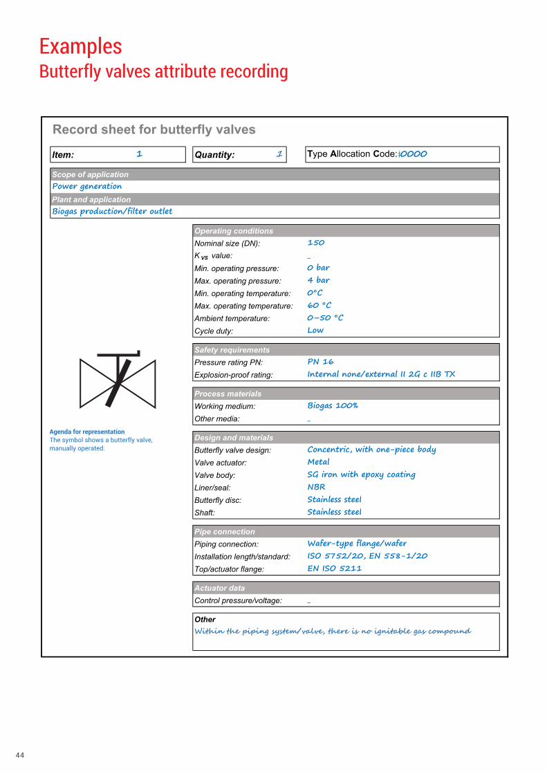
Scope of applicationPower generationPlant and applicationBiogas production/filter outlet
Operating conditionsNominal size (DN): 150K VS value: _Min. operating pressure: 0 barMax. operating pressure: 4 barMin. operating temperature: 0°CMax. operating temperature: 60 °CAmbient temperature: 0–50 °CCycle duty: Low
Safety requirementsPressure rating PN: PN 16Explosion-proof rating: Internal none/external II 2G c IIB TX
Process materialsWorking medium: Biogas 100%Other media: _
Design and materialsButterfly valve design: Concentric, with one-piece bodyValve actuator: MetalValve body: SG iron with epoxy coatingLiner/seal: NBRButterfly disc: Stainless steelShaft: Stainless steel
Pipe connectionPiping connection: Wafer-type flange/waferInstallation length/standard: ISO 5752/20, EN 558-1/20Top/actuator flange: EN ISO 5211
Actuator dataControl pressure/voltage: _
OtherWithin the piping system/valve, there is no ignitable gas compound
Examples Butterfly valves attribute recording
Agenda for representation The symbol shows a butterfly valve, manually operated .
www.gemu-group.com 45
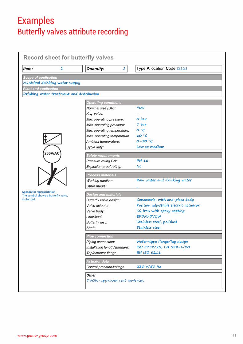
Record sheet for butterfly valves
Item: 1 Quantity: 1 Type Allocation Code:�����
Scope of applicationMunicipal drinking water supplyPlant and applicationDrinking water treatment and distribution
Operating conditionsNominal size (DN): 400K VS value: _Min. operating pressure: 0 barMax. operating pressure: 7 barMin. operating temperature: 0 °CMax. operating temperature: 60 °CAmbient temperature: 0–50 °CCycle duty: Low to medium
Safety requirementsPressure rating PN: PN 16Explosion-proof rating: No
Process materialsWorking medium: Raw water and drinking waterOther media: _
Design and materialsButterfly valve design: Concentric, with one-piece bodyValve actuator: Position adjustable electric actuatorValve body: SG iron with epoxy coatingLiner/seal: EPDM/DVGWButterfly disc: Stainless steel, polishedShaft: Stainless steel
Pipe connectionPiping connection: Wafer-type flange/lug designInstallation length/standard: ISO 5752/20, EN 558-1/20Top/actuator flange: EN ISO 5211
Actuator dataControl pressure/voltage: 230 V/50 Hz
OtherDVGW-approved seal material
Examples Butterfly valves attribute recording
230V/AC
Agenda for representation The symbol shows a butterfly valve, motorized .
46
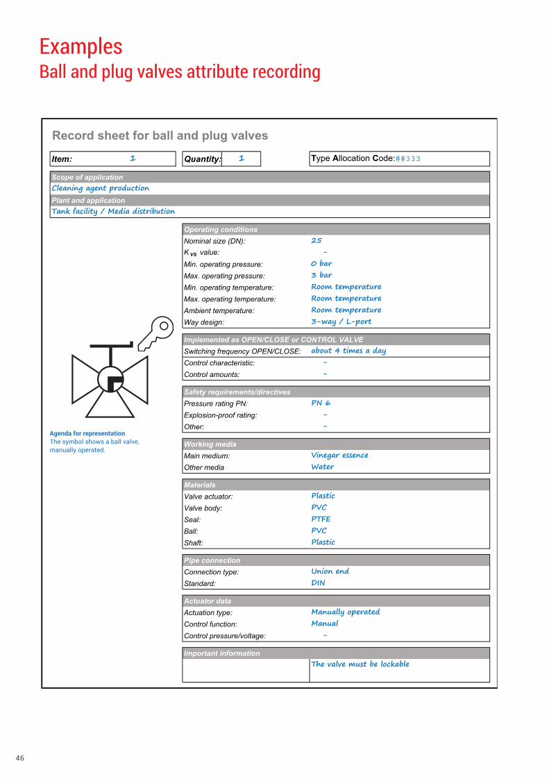
Record sheet for ball and plug valves
Item: 1 Quantity: 1 Type Allocation Code:�����
Scope of applicationCleaning agent productionPlant and applicationTank facility / Media distribution
Operating conditionsNominal size (DN): 25K VS value: -Min. operating pressure: 0 barMax. operating pressure: 3 barMin. operating temperature: Room temperatureMax. operating temperature: Room temperatureAmbient temperature: Room temperatureWay design: 3-way / L-port
Implemented as OPEN/CLOSE or CONTROL VALVESwitching frequency OPEN/CLOSE: about 4 times a dayControl characteristic: -Control amounts: -
Safety requirements/directivesPressure rating PN: PN 6Explosion-proof rating: -Other: -
Working mediaMain medium: Vinegar essence Other media Water
MaterialsValve actuator: PlasticValve body: PVCSeal: PTFEBall: PVCShaft: Plastic
Pipe connectionConnection type: Union endStandard: DIN
Actuator dataActuation type: Manually operatedControl function: ManualControl pressure/voltage: -
Important informationThe valve must be lockable
Examples Ball and plug valves attribute recording
Agenda for representation The symbol shows a ball valve, manually operated .
www.gemu-group.com 47
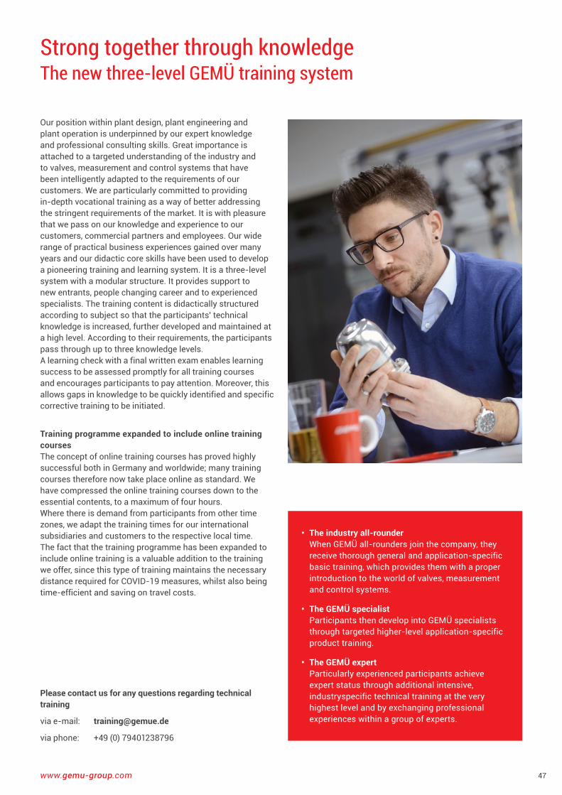
Strong together through knowledge The new three-level GEMÜ training system
Please contact us for any questions regarding technical training
via e-mail: [email protected]
via phone: +49 (0) 79401238796
• The industry all-rounder When GEMÜ all-rounders join the company, they receive thorough general and application-specific basic training, which provides them with a proper introduction to the world of valves, measurement and control systems .
• The GEMÜ specialist Participants then develop into GEMÜ specialists through targeted higher-level application-specific product training .
• The GEMÜ expert Particularly experienced participants achieve expert status through additional intensive, industry specific technical training at the very highest level and by exchanging professional experiences within a group of experts .
Our position within plant design, plant engineering and plant operation is underpinned by our expert knowledge and professional consulting skills . Great importance is attached to a targeted understanding of the industry and to valves, measurement and control systems that have been intelligently adapted to the requirements of our customers . We are particularly committed to providing in-depth vocational training as a way of better addressing the stringent requirements of the market . It is with pleasure that we pass on our knowledge and experience to our customers, commercial partners and employees . Our wide range of practical business experiences gained over many years and our didactic core skills have been used to develop a pioneering training and learning system . It is a three-level system with a modular structure . It provides support to new entrants, people changing career and to experienced specialists . The training content is didactically structured according to subject so that the participants' technical knowledge is increased, further developed and maintained at a high level . According to their requirements, the participants pass through up to three knowledge levels .A learning check with a final written exam enables learning success to be assessed promptly for all training courses and encourages participants to pay attention . Moreover, this allows gaps in knowledge to be quickly identified and specific corrective training to be initiated .
Training programme expanded to include online training coursesThe concept of online training courses has proved highly successful both in Germany and worldwide; many training courses therefore now take place online as standard . We have compressed the online training courses down to the essential contents, to a maximum of four hours . Where there is demand from participants from other time zones, we adapt the training times for our international subsidiaries and customers to the respective local time . The fact that the training programme has been expanded to include online training is a valuable addition to the training we offer, since this type of training maintains the necessary distance required for COVID-19 measures, whilst also being time-efficient and saving on travel costs .
48
Schlosshotel IngelfingenWeinmanufaktur Ingelfinger FassSchlossstraße 13 and 14 74653 Ingelfingen, Germany Phone 07940 I [email protected] www.schloss-hotel-ingelfingen.de
Hot food is served at the following times: Mon–Sun, noon–1.30 p.m. and 6 p.m.–9.45 p.m.Sun and bank holidays until 9 p.m.Winery opening hours: Wen–Fri, 3 p.m.–7 p.m., Sat, 10 a.m.–2 p.m.or by prior arrangement
A COMPANY OF THE GEMÜ GROUP
Our guests are our top priority. Sit back and enjoy the attentive service of our restaurant, the hotel bar (with SKY Sport) or the peace and quiet of the terrace.
Held in the winery or the unique Ingelfinger Fass, celebratory oc-casions and indulgent wine events are transformed into an unforgettable experience. Be inspired by selected wines from our winery that are rich in character.
Winewith great Unwind L E T U S S P O I L Y O U
DISCOVER
OUR
WINERY
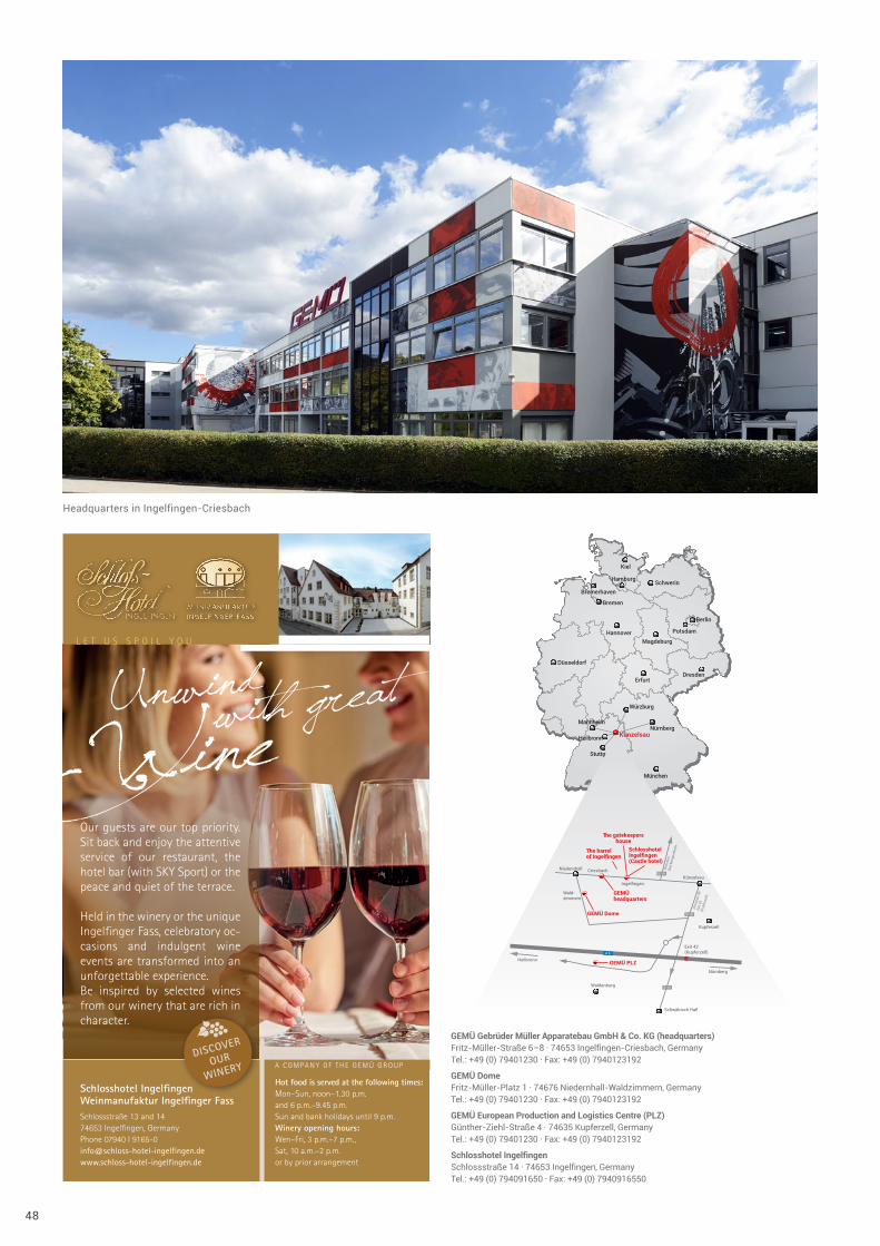
Headquarters in Ingelfingen-Criesbach
Nürnberg
Heilbronn
Mannheim
Künzelsau
Würzburg
Stuttgart
München
Erfurt
Düsseldorf
Dresden
Magdeburg
Potsdam
Berlin
Hannover
Bremen
Bremerhaven
Hamburg Schwerin
Kiel
Ingelfingen
Dire
ctio
nBa
d M
erge
nthe
im
Dire
ctio
n A6
Exit
42(K
upfe
rzel
l)
Künzelsau
Niedernhall
Wald-zimmern
Criesbach
Waldenburg
Kupferzell
GEMÜheadquarters
The barrelof Ingelfingen
The gatekeepershouse
SchlosshotelIngelfingen(Castle hotel)
GEMÜ Dome
GEMÜ PLZHeilbronn
Schwäbisch Hall
Nürnberg
Exit 42(Kupferzell)
GEMÜ Gebrüder Müller Apparatebau GmbH & Co. KG (headquarters) Fritz-Müller-Straße 6–8 · 74653 Ingelfingen-Criesbach, Germany Tel .: +49 (0) 79401230 · Fax: +49 (0) 7940123192
GEMÜ Dome Fritz-Müller-Platz 1 · 74676 Niedernhall-Waldzimmern, Germany Tel .: +49 (0) 79401230 · Fax: +49 (0) 7940123192
GEMÜ European Production and Logistics Centre (PLZ) Günther-Ziehl-Straße 4 · 74635 Kupferzell, Germany Tel .: +49 (0) 79401230 · Fax: +49 (0) 7940123192
Schlosshotel Ingelfingen Schlossstraße 14 · 74653 Ingelfingen, Germany Tel .: +49 (0) 794091650 · Fax: +49 (0) 7940916550
www.gemu-group.com 49
AUSTRALIAGEMÜ Australia Pty . LtdUnit 4 - 8/10 Yandina RoadWest Gosford, NSW 2250Phone: +61-2-43 23 44 93Fax: +61-2-43 23 44 96mail@gemu .com .au
AUSTRIAGEMÜ GmbHEuroparing F13 4012345 Brunn am GebirgePhone: +43 2236 30 43 45-0Fax:+43 2236 30 43 45-31info@gemue .at
BELGIUMGEMÜ Valves bv/srlKoning Albert 1 laan, 64 1780 WemmelPhone: +32 2 702 09 00Fax: +32 2 705 55 03info@gemue .be
BRAZIL / LATAMGEMÜ Indústria de ProdutosPlásticos e Metalúrgicos Ltda .Rue Marechal Hermes, 114183 .065-000 São José dos PinhaisParanáPhone: +55 41 3382 2425Fax: +55 41 3382 3531gemu@gemue .com .br
CANADAGEMÜ Valves Canada Inc .2572 Daniel-Johnson BoulevardLaval, QuebecH7T 2R8Phone: +1-450-902-2690Fax: +1-404-3 44 4003info@gemu .com
CHINA GEMÜ Valves (China) Co ., LtdNo .518, North Hengshahe Road Minhang District, 201108 ShanghaiPhone: +86-21-2409 9878info@gemue .com .cn
DENMARKGEMÜ ApSBrydehusvej 13, 22750 BallerupPhone: +45 70 222 516info@gemue .dk
FRANCEGEMÜ S .A .S1 Rue Jean Bugatti67120 DuppigheimPhone: +33-3 88 48 21 00info@gemu .fr
INTERCARAT1 Rue Jean Bugatti67120 DuppigheimPhone: +33-3 88 48 21 20sales@intercarat .com
GERMANYGEMÜ Gebr . Müller GmbH & Co . KGFritz-Müller-Straße 6 - 874653 Ingelfingen-CriesbachPostfach 3074665 Ingelfingen-Criesbach
Phone: +49 (0)7940-12 30Fax: +49 (0)7940-12 31 92 (Domestic) Fax: +49 (0)7940-12 32 24 (Export)info@gemue .de
Inevvo solutions GmbH & Co . KGFritz-Müller-Platz 174676 Niedernhall-WaldzimmernPhone: +49 (0)7940-12 38 681info@inevvo-solutions .com
GREAT BRITAIN GEMÜ Valves Ltd .10 Olympic WayBirchwood, WarringtonWA2 0YLPhone:+44-19 25-82 40 44Fax:+44-19 25-82 80 02info@gemu .co .uk
HONG KONGGEMÜ (Hong Kong) Co ., Ltd .Room 2015, Tower B, Regent Centre, 70 TA Chuen Ping StreetKwai Chung, N .T ., Hong KongP .R . ChinaPhone: +852 6873 8280Fax: +852 6873 8280info@gemue .com .cn
INDIAGEMÜ Branch Office India637 Building, Office No . 101 & 104, 1st Floor,Gulbai Tekra 2nd Lane, Near Panchvati,Ahmedabad - 380006, GujaratPhone: +91-79-6134 4423Fax: +91-79-25450439sales@gemu .in
INDONESIAGEMU Valves Pte Ltd(Indonesia Representative Office)Rukan Mangga Dua SquareBlock F17, 2nd FloorJl . Gunung Sahari Raya No . 1Jakarta Utara 14420Phone: +62 (21) - 6231 0035Fax +62 (21) - 2907 4643info@gemu .co .id
IRELANDGEMÜ Ireland Ltd15 Eastgate DriveEastgate Business ParkLittle IslandCo . CorkPhone: +353 (0)21 4232023Fax: +353 (0)21 4232024info@gemu .ie
ITALYGEMÜ S .r .l .Via Giovanni Gentile, 320157 MilanoPhone: +39-02-40044080Fax: +39-02-40044081info@gemue .it
JAPANGEMÜ Japan Co ., Ltd .2-5-6, Aoi, Higashi-ku, Nagoya, Aichi, 461-0004Phone: +81-52-936-2311Fax: +81-52-936-2312info@gemu .jp
MALAYSIAGEMU VALVES MALAYSIA SDN . BHD .D-2-01, Capital 4,Oasis SquareNo . 2, Jalan PJU 1A/7AAra Damansara47301 Petaling JayaSelangor Darul EhsanPhone: +(603)- 7832 7640Fax: +(603)- 7832 7649info@gemu .com .sg
MEXICOGEMU Valvulas S .A . de C .V .German Centre, Av . Santa Fe No . 170 – OF . 5-1-05Col . Lomas de Santa Fe, Del . Alvaro Obregon01210 Mexico, D .F .Phone: +52 55 7090 4161 +52 55 7090 4179
RUSSIA OOO „GEMÜ GmbH“Uliza Shipilovskaya, 28A 115563, MoskauPhone: +7(495) 662-58-35Fax: +7(495) 662-58-35info@gemue .ru
SINGAPOREGEMÜ Valves PTE . LTD .25 International Business ParkGerman Centre #03-73/75Singapore 609916Phone: +65-65 62 76 40Fax: +65-65 62 76 49info@gemu .com .sg
SOUTH AFRICA GEMÜ Valves Africa Pty . LtdCnr Olympic Duel Avenue And Angus Cresent,Northlands Business Park (Stand 379),New Market RoadRandburgPhone: +27 11 462 7795Fax: +27 11 462 4226info@gemue .co .za
SWEDENGEMÜ Armatur ABHeljesvägen 8437 36 LindomePhone: +46-31-996500order@gemu .se
SWITZERLANDGEMÜ GmbH Seetalstr . 2106032 EmmenPhone: +41-41-7 99 05 05Fax: +41-41-7 99 05 85info@gemue .ch
GEMÜ Vertriebs AGLettenstrasse 36343 RotkreuzPhone: +41-41-7 99 05 55Fax: +41-41-7 99 05 85vertriebsag@gemue .ch
TAIWANGEMÜ Taiwan Ltd .9F .-5, No .8, Ziqiang S . Rd .Zhubei CityHsinchu County 302, Taiwan (R .O .C .)Phone: +886-3-550-7265Fax: +886-3-550-7201office@gemue .tw
UNITED STATESGEMÜ Valves Inc .3800 Camp Creek ParkwaySuite 120, Building 2600Atlanta, Georgia 30331Phone: +1-678-5 53 34 00Fax: +1-404-3 44 93 50info@gemu .com
In addition to these subsidiaries, GEMÜ has a global partner network .
Contact details:www.gemu-group.com/en_GB/kontakte/
GEMÜ Manufacturing siteGEMÜ Produktionsstandort
GEMÜ SubsidiaryGEMÜ Tochtergesellschaft
GEMÜ manufacturing site
GEMÜ subsidiary
Worldwide presence

www.gemu-group.com
GEMÜ Gebr. Müller Apparatebau GmbH & Co. KG Fritz-Müller-Straße 6-8 · D-74653 Ingelfingen-Criesbach Phone +49 (0)7940 123-0 · info@gemue .de Su
bjec
t to
alte
ratio
n · 1
0/20
20