Process Indicator K3HB-X power supply models require a control power supply capacity of...
18
CSM_K3HB-X_DS_E_4_1 1 Process Indicator K3HB-X A Process Indicator Ideal for Discriminating and Displaying Measurements for Voltage/Current Signals • Easy recognition of judgement results using color display that can be switched between red and green. • Equipped with a position meter for monitoring operating status trends. • External event input allows use in various measurement and discrimina- tion applications. • Series expanded to include DeviceNet models. • Short body with depth of only 95 mm (from behind the front panel), or 97 mm for DeviceNet models. • UL certification approval (Certification Mark License). • CE Marking conformance by third party assessment body. • Water-resistant enclosure conforms to NEMA 4X (equivalent to IP66). • Capable of high-speed sampling at 50 times per second (20 ms) • Easy-to-set two-point scaling allows conversion and display of any user- set values. Refer to Safety Precautions for All Digital Panel Meters. Model Number Structure ■ Model Number Legend Base Units and Optional Boards can be ordered individually or as sets. Base Units 1. Input Sensor Code VD: DC voltage input AD: DC current input VA: AC voltage input AA: AC current input 5. Supply Voltage 100-240 VAC: 100 to 240 VAC 24 VAC/VDC: 24 VAC/VDC Base Units with Optional Boards 2. Sensor Power Supply/Output Type Code None: None CPA: Relay output (PASS: SPDT) + Sensor power supply (12 VDC +/−10%, 80 mA) (See note 1.) L1A: Linear current output (0 to 20 or 4 to 20 mA DC) + Sensor power supply (12 VDC +/−10%, 80 mA) (See note 2.) L2A: Linear voltage output (0 to 5, 1 to 5, or 0 to 10 VDC) + Sensor power supply (12 VDC +/−10%, 80 mA) (See note 2.) A: Sensor power supply (12 VDC +/−10%, 80 mA) FLK1A: Communications (RS-232C) + Sensor power supply (12 VDC +/−10%, 80 mA) (See note 2.) FLK3A: Communications (RS-485) + Sensor power supply (12 VDC +/−10%, 80 mA) (See note 2.) Optional Board Sensor Power Supply/Output Boards Relay/Transistor Output Boards Event Input Boards 3. Relay/Transistor Output Type Code None: None C1: Relay contact (H/L: SPDT each) C2: Relay contact (HH/H/LL/L: SPST-NO each) T1: Transistor (NPN open collector: HH/H/PASS/L/LL) T2: Transistor (PNP open collector: HH/H/PASS/L/LL) BCD∗: BCD output + transistor output (NPN open collector: HH/H/PASS/L/ LL) DRT: DeviceNet (See note 2.) ∗ A Special BCD Output Cable (sold separately) is required. 4. Event input Type Code None: None 1: 5 inputs (M3 terminal blocks), NPN open collector 2: 8 inputs (10-pin MIL connector), NPN open collector 3: 5 inputs (M3 terminal blocks), PNP open collector 4: 8 inputs (10-pin MIL connector), PNP open collector Note: 1. CPA can be combined with relay outputs only. 2. Only one of the following can be used by each Digital Indicator: RS-232C/RS-485 communications, a linear output, or DeviceNet communications. Accessories (Sold Separately) K32-DICN: Special Cable (for event inputs, with 8-pin connector) K32-BCD: Special BCD Output Cable Rubber Packing Note: Rubber packing is provided with the Controller. 1 K3HB-X@ 5 1 2 34 K3HB-X@-@@@ 5 2 K33-@ 3 K34-@ 4 K35-@ Model K32-P1
Transcript of Process Indicator K3HB-X power supply models require a control power supply capacity of...

CSM_K3HB-X_DS_E_4_1
1
Process Indicator
K3HB-XA Process Indicator Ideal for Discriminating and Displaying Measurements for Voltage/Current Signals• Easy recognition of judgement results using color display that can be
switched between red and green.• Equipped with a position meter for monitoring operating status trends.• External event input allows use in various measurement and discrimina-
tion applications.• Series expanded to include DeviceNet models.• Short body with depth of only 95 mm (from behind the front panel), or
97 mm for DeviceNet models.• UL certification approval (Certification Mark License).• CE Marking conformance by third party assessment body.• Water-resistant enclosure conforms to NEMA 4X (equivalent to IP66).• Capable of high-speed sampling at 50 times per second (20 ms)• Easy-to-set two-point scaling allows conversion and display of any user-
set values.
Refer to Safety Precautions for All Digital Panel Meters.
Model Number Structure Model Number LegendBase Units and Optional Boards can be ordered individually or as sets.
Base Units
1. Input Sensor CodeVD: DC voltage inputAD: DC current inputVA: AC voltage inputAA: AC current input
5. Supply Voltage
100-240 VAC: 100 to 240 VAC24 VAC/VDC: 24 VAC/VDC
Base Units with Optional Boards
2. Sensor Power Supply/Output Type CodeNone: NoneCPA: Relay output (PASS: SPDT) + Sensor power supply
(12 VDC +/−10%, 80 mA) (See note 1.)L1A: Linear current output (0 to 20 or 4 to 20 mA DC) + Sensor power supply
(12 VDC +/−10%, 80 mA) (See note 2.)L2A: Linear voltage output (0 to 5, 1 to 5, or 0 to 10 VDC) + Sensor power supply
(12 VDC +/−10%, 80 mA) (See note 2.)A: Sensor power supply (12 VDC +/−10%, 80 mA)FLK1A: Communications (RS-232C) + Sensor power supply
(12 VDC +/−10%, 80 mA) (See note 2.)FLK3A: Communications (RS-485) + Sensor power supply
(12 VDC +/−10%, 80 mA) (See note 2.)
Optional BoardSensor Power Supply/Output Boards
Relay/Transistor Output Boards
Event Input Boards
3. Relay/Transistor Output Type CodeNone: NoneC1: Relay contact (H/L: SPDT each)C2: Relay contact (HH/H/LL/L: SPST-NO each)T1: Transistor (NPN open collector: HH/H/PASS/L/LL)T2: Transistor (PNP open collector: HH/H/PASS/L/LL)BCD∗: BCD output + transistor output (NPN open collector: HH/H/PASS/L/
LL)DRT: DeviceNet (See note 2.)∗ A Special BCD Output Cable (sold separately) is required.
4. Event input Type CodeNone: None1: 5 inputs (M3 terminal blocks), NPN open collector2: 8 inputs (10-pin MIL connector), NPN open collector3: 5 inputs (M3 terminal blocks), PNP open collector4: 8 inputs (10-pin MIL connector), PNP open collector
Note: 1. CPA can be combined with relay outputs only.2. Only one of the following can be used by each Digital Indicator: RS-232C/RS-485 communications, a linear output, or DeviceNet communications.
Accessories (Sold Separately)K32-DICN: Special Cable (for event inputs, with 8-pin connector)K32-BCD: Special BCD Output Cable
Rubber Packing
Note: Rubber packing is provided with the Controller.
1K3HB-X@
5 1 2 3 4K3HB-X@-@@@
5
2K33-@
3K34-@
4K35-@
Model
K32-P1

K3HB-X
2
Specifications
Ratings
Note: 1. DC power supply models require a control power supply capacity of approximately 1 A per Unit when power is turned ON. Particularattention is required when using two or more DC power supply models. The OMRON S8VS-series DC Power Supply Unit is recommend-ed.
2. PNP input types are also available.3. For K3HB-series DeviceNet models, use only the DeviceNet Connector included with the product. The crimp terminals provided are for
Thin Cables.
Power supply voltage 100 to 240 VAC (50/60 Hz), 24 VAC/VDC, DeviceNet power supply: 24 VDC
Allowable power supply voltage range 85% to 110% of the rated power supply voltage, DeviceNet power supply: 11 to 25 VDC
Power consumption(See note 1.)
100 to 240 V: 18 VA max. (max. load)24 VAC/DC: 11 VA/7 W max. (max. load)
Current consumption DeviceNet power supply: 50 mA max. (24 VDC)
Input DC voltage, DC current, AC voltage, AC current
A/D conversion method Delta-Sigma method
External power supply 12 VDC ±10%, 80 mA (models with external power supply only)
Event inputs (See note 2.)
Timing input NPN open collector or no-voltage contact signalON residual voltage: 3 V max.ON current at 0 Ω: 17 mA max.Max. applied voltage: 30 VDC max.OFF leakage current: 1.5 mA max.
Startup compensa-tion timer input
NPN open collector or no-voltage contact signalON residual voltage: 2 V max.ON current at 0 Ω: 4 mA max.Max. applied voltage: 30 VDC max.OFF leakage current: 0.1 mA max.
Hold input
Reset input
Forced-zero input
Bank input
Output ratings (de-pends on the mod-el)
Relay output 250 VAC, 30 VDC, 5 A (resistive load)Mechanical life expectancy: 5,000,000 operations, Electrical life expectancy: 100,000 operations
Transistor output Maximum load voltage: 24 VDC, Maximum load current: 50 mA, Leakage current: 100 µA max.
Linear output Linear output 0 to 20 mA DC, 4 to 20 mA DC:Load: 500 Ω max, Resolution: Approx. 10,000, Output error: ±0.5% FS
Linear output 0 to 5 VDC, 1 to 5 VDC, 0 to 10 VDC:Load: 5 kΩ max, Resolution: Approx. 10,000, Output error: ±0.5% FS(1 V or less: ±0.15 V; no output for 0 V or less)
Display method Negative LCD (backlit LED) display7-segment digital display (Character height: PV: 14.2 mm (green/red); SV: 4.9 mm (green)
Main functions Scaling function, measurement operation selection, averaging, previous average value comparison, forced-ze-ro, zero-limit, output hysteresis, output OFF delay, output test, teaching, display value selection, display color selection, key protection, bank selection, display refresh period, maximum/minimum hold, reset
Ambient operating temperature −10 to 55°C (with no icing or condensation)
Ambient operating humidity 25% to 85%
Storage temperature −25 to 65°C (with no icing or condensation)
Altitude 2,000 m max.
Accessories Watertight packing, 2 fixtures, terminal cover, unit stickers, instruction manual. DeviceNet models also include a DeviceNet connector (Hirose HR31-5.08P-5SC(01)) and crimp terminals (Hirose HR31-SC-121) (See note 3.)
K3HB-X
3
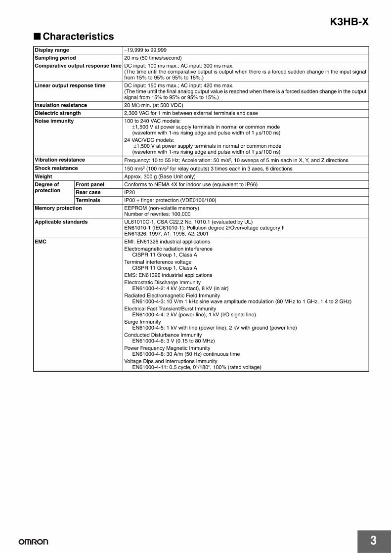
CharacteristicsDisplay range −19,999 to 99,999
Sampling period 20 ms (50 times/second)
Comparative output response time DC input: 100 ms max.; AC input: 300 ms max.(The time until the comparative output is output when there is a forced sudden change in the input signal from 15% to 95% or 95% to 15%.)
Linear output response time DC input: 150 ms max.; AC input: 420 ms max.(The time until the final analog output value is reached when there is a forced sudden change in the output signal from 15% to 95% or 95% to 15%.)
Insulation resistance 20 MΩ min. (at 500 VDC)
Dielectric strength 2,300 VAC for 1 min between external terminals and case
Noise immunity 100 to 240 VAC models:±1,500 V at power supply terminals in normal or common mode(waveform with 1-ns rising edge and pulse width of 1 µs/100 ns)
24 VAC/VDC models: ±1,500 V at power supply terminals in normal or common mode(waveform with 1-ns rising edge and pulse width of 1 µs/100 ns)
Vibration resistance Frequency: 10 to 55 Hz; Acceleration: 50 m/s2, 10 sweeps of 5 min each in X, Y, and Z directions
Shock resistance 150 m/s2 (100 m/s2 for relay outputs) 3 times each in 3 axes, 6 directions
Weight Approx. 300 g (Base Unit only)
Degree of protection
Front panel Conforms to NEMA 4X for indoor use (equivalent to IP66)
Rear case IP20
Terminals IP00 + finger protection (VDE0106/100)
Memory protection EEPROM (non-volatile memory)Number of rewrites: 100,000
Applicable standards UL61010C-1, CSA C22.2 No. 1010.1 (evaluated by UL)EN61010-1 (IEC61010-1): Pollution degree 2/Overvoltage category IIEN61326: 1997, A1: 1998, A2: 2001
EMC EMI: EN61326 industrial applicationsElectromagnetic radiation interference
CISPR 11 Group 1, Class ATerminal interference voltage
CISPR 11 Group 1, Class AEMS: EN61326 industrial applicationsElectrostatic Discharge Immunity
EN61000-4-2: 4 kV (contact), 8 kV (in air)Radiated Electromagnetic Field Immunity
EN61000-4-3: 10 V/m 1 kHz sine wave amplitude modulation (80 MHz to 1 GHz, 1.4 to 2 GHz)Electrical Fast Transient/Burst Immunity
EN61000-4-4: 2 kV (power line), 1 kV (I/O signal line)Surge Immunity
EN61000-4-5: 1 kV with line (power line), 2 kV with ground (power line)Conducted Disturbance Immunity
EN61000-4-6: 3 V (0.15 to 80 MHz)Power Frequency Magnetic Immunity
EN61000-4-8: 30 A/m (50 Hz) continuous timeVoltage Dips and Interruptions Immunity
EN61000-4-11: 0.5 cycle, 0°/180°, 100% (rated voltage)

K3HB-X
4
Input Range (Measurement Range and Accuracy) CAT II
Note: 1. The accuracy is for an input frequency range of 40 Hz to 1 kHz (except for AD current input A and B ranges of 50 to 60 Hz) and an ambienttemperature of 23 ±5°C. The error, however, increases below 10% of the maximum input value.DC voltage input (all ranges): 10% or less of max. input = ±0.15% FSDC current input (all ranges): 10% or less of max. input = ±0.1% FSAC voltage input (A: 0.0 to 400.0 V): 10% or less of max. input = ±0.15% FSAC voltage input (B: 0.00 to 199.99 V): 10% or less of max. input = ±0.2% FSAC voltage input (C: 0.000 to 19.999 V; D: 0.0000 to 1.9999 V): 10% or less of max. input = ±1.0% FSAC current input (A: 0.000 to 10.000 A): 10% or less of max. input = ±0.25% FSAC current input (B: 0.0000 to 1.9999 A): 10% or less of max. input = ±0.5% FSAC current input (C: 0.00 to 199.99 mA; D: 0.000 to 19.999 A): 10% or less of max. input = ±0.15% FSWhen DC voltage input models are used with a ±1.9999 V range, make sure that the connections between input terminals are not open.If the input terminals are open, the display will show large variations. Connect resistance of approximately 1 MΩ between the input ter-minals if they are open.
2. The letters “rdg” mean “reading” and refer to the input error.3. The value (0.5 VA CT) is the VA consumption of the internal CT (current transformer).
4. The K3HB-XVA@@ complies with UL standards when the applied input voltage is within the range 0 to 150 VAC.If the input voltage is higher than 150 VAC, install an external transformer or take other measures to drop the voltage to 150 VAC or lower.
Input type Range Set value Measurement range Input impedance
Accuracy Allowable instantaneous overload (30 s)
K3HB-XVD DC voltage
A a Ud ±199.99 V 10 MΩ min. ±0.1%rdg ± 1 digit max.
±400 V
B b Ud ±19.999 V 1 MΩ min. ±200 V
C c Ud ±1.9999 V
D d Ud 1.0000 to 5.0000 V
K3HB-XADDC current
A a ad ±199.99 mA 1 Ω max. ±0.1%rdg ± 1 digit max.
±400 mA
B b ad ±19.999 mA 10 Ω max. ±200 mA
C c ad ±1.9999 mA 33 Ω max.
D d ad 4.000 to 20.000 mA 10 Ω max.
K3HB-XVAAC voltage (See note 4.)
A a Ua 0.0 to 400.0 V 1 MΩ min. ±0.3%rdg ± 5 digits max.
700 V
B b Ua 0.00 to 199.99 V
C c Ua 0.000 to 19.999 V ±0.5%rdg ± 10 digits max.
400 V
D d Ua 0.0000 to 1.9999 V
K3HB-XAAAC current
A a aa 0.000 to 10.000 A (0.5 VA CT)(See note 3.)
±0.5%rdg ± 20 digits max.
20 A
B b aa 0.0000 to 1.9999 A (0.5 VA CT)(See note 3.)
C c aa 0.00 to 199.99 mA 1 Ω max. ±0.5%rdg ± 10 digits max.
2 A
D d aa 0.000 to 19.999 mA 10 Ω max.
COM
+
−
±1.9999 V
1 MΩ
E2
E3
E4
E5
E6

K3HB-X
5
Common Specifications
Event Input Ratings
Output Ratings
Contact Output Transistor Output
Linear Output
Serial Communications Output
Note: For details on serial and DeviceNet communications, refer tothe Digital Indicator K3HB Communications User's Manual(Cat.No. N129).
BCD Output I/O Ratings (Input Signal Logic: Negative)
Note: For details on serial and DeviceNet communications, refer tothe Digital Indicator K3HB Communications User's Manual(Cat.No. N129).
Input type S-TMR, HOLD, RESET, ZERO, BANK1, BANK2, BANK4
TIMING
Contact ON: 1 kΩ max., OFF: 100 kΩ min. ---
No-contact ON residual voltage: 2 V max.OFF leakage current: 0.1 mA max.Load current: 4 mA max.Maximum applied voltage: 30 VDC max.
ON residual voltage: 3 V max.OFF leakage current: 1.5 mA max.Load current: 17 mA max.Maximum applied voltage: 30 VDC max.
Item Resistive loads(250 VAC, cosφ=1; 30 VDC, L/R=0 ms)
Inductive loads(250 VAC, closed circuit, cosφ=0.4;
30 VDC, L/R=7 ms)
Rated load 5 A at 250 VAC5 A at 30 VDC
1 A at 250 VAC1 A at 30 VDC
Mechanical life expectancy
5,000,000 operations
Electrical life expectancy
100,000 operations
Maximum load voltage 24 VDC
Maximum load current 50 mA
Leakage current 100 µA max.
Item 0 to 20 mA 4 to 20 mA 0 to 5 V 1 to 5 V 0 to 10 V
Allowable load impedance 500 Ω max. 5 kΩ min.
Resolution Approx. 10,000
Output error ±0.5%FS ±0.5%FS (1 V or less: ±0.15 V; no output for 0 V or less.)
Item RS-232C, RS-485
Communications method Half duplex
Synchronization method Start-stop synchronization
Baud rate 9,600, 19,200, or 38,400 bps
Transmission code ASCII
Data length 7 bits or 8 bits
Stop bit length 2 bits or 1 bit
Error detection Vertical parity and FCS
Parity check Odd, even
I/O signal name Item Rating
Inputs REQUESTHOLDMAXMINRESET
Input signal No-voltage contact input
Input current for no-voltage input
10 mA
Signal level
ON voltage 1.5 V max.
OFF voltage 3 V min.
Outputs DATAPOLARITYOVERDATA VALIDRUN
Maximum load voltage
24 VDC
Maximum load current
10 mA
Leakage current 100 µA max.
HHHPASSLLL
Maximum load voltage
24 VDC
Maximum load current
50 mA
Leakage current 100 µA max.

K3HB-X
6
DeviceNet Communications
Internal Block Diagram
Communications protocol Conforms to DeviceNet
Supported communi-cations
Remote I/O communications Master-Slave connection (polling, bit-strobe, COS, cyclic)Conforms to DeviceNet communications standards.
I/O allocations Allocate any I/O data using the Configurator.Allocate any data, such as DeviceNet-specific parameters and variable area for Digital Indicators.Input area: 2 blocks, 60 words max.Output area: 1 block, 29 words max.(The first word in the area is always allocated for the Output Execution Enabled Flags.)
Message communications Explicit message communicationsCompoWay/F communications commands can be executed (using explicit message communications)
Connection methods Combination of multi-drop and T-branch connections (for trunk and drop lines)
Baud rate DeviceNet: 500, 250, or 125 Kbps (automatic follow-up)
Communications media Special 5-wire cable (2 signal lines, 2 power supply lines, 1 shield line)
Communications distance
Baud rate Network length (max.)
Drop line length (max.)
Total drop line length (max.)
500 Kbps 100 m (100 m) 6 m 39 m
250 Kbps 100 m(250 m)
6 m 78 m
125 Kbps 100 m(500 m)
6 m 156 m
The values in parentheses are for Thick Cable.
Communications power supply 24-VDC DeviceNet power supply
Allowable voltage fluctuation range 11 to 25-VDC DeviceNet power supply
Current consumption 50 mA max. (24 VDC)
Maximum number of nodes 64 (DeviceNet Configurator is counted as one node when connected)
Maximum number of slaves 63
Error control checks CRC errors
DeviceNet power supply Supplied from DeviceNet communications connector
ADC
EEP-ROM
Analog input
Event input
DeviceNet
X
VO
VO
BCD I/O
Sensor powersupply
Keys
Micro-computer
Waveformshaping circuit
Drivecircuit
Indications
Drivecircuit
Digital input circuit
Filter
Input circuit
BCD• Input circuit• Output circuit• Transistor output circuit
Drivecircuit
Drivecircuit
Drivecircuit
Drivecircuit
Transistoroutput
Relay output
Linear output
Communications
DeviceNetcircuit
Communi-cationsdriver
Power supply
Power supply circuit (isolated)
VDD VCOM
DC-DC
Converter (isolated)
Linear outputcircuit

K3HB-X
7
Power Supply Derating Curve for Sensor (Reference Value)
Note: 1. The above values are for standard mounting. The derating curve differs depending on the mounting conditions.2. Do not use the Sensor outside of the derating area (i.e., do not use it in the area labeled A in the above graphics). Doing so may occa-
sionally cause deterioration or damage to internal components.
Component Names and Functions
140
120
100
80
60
40
20
0−20 −10 0 10 20 30 40 50 60
Ambient temperature (°C)
Max. current (mA)
1140
120
100
80
60
40
20
0−20 −10 0 10 20 30 40 50 60
Ambient temperature (°C)
Max. current (mA)
1
With 12 V With 10 V
UPMODELEVEL
T-ZRZero
CMW
Max
L
Min
Hold
MAX/MIN
TG HH H
T LL L
HH
H
P
L
LL
SHIFT
MAX/MIN Key LEVEL Key MODE Key SHIFT Key UP Key
When changing a set value, this key is used to change the actual value.When a measurement value is displayed, this key is used to execute or clear the forced-zero function or to execute teaching.
Used to change parameter settings. When changing a set value, this key is used to move along the digits.
Used to switch the parameters displayed.
Used to switch level.Used to switch the display between the PV, maximum value, and minimum value and to reset the maximum and minimum values.
PV display
SV display
Position meter
SV display status indicators
Displays SV and monitor values.
HH, H, L, LL
Max/Min status indicator
Level/bank display
Status indicators
Display
Display the status of comparative outputs.
T-ZR
Zero
Hold
Function
T
TG
Turns ON when the maximum value or minimum value is displayed in the RUN level.
In RUN level, displays the bank if the bank function is ON. (Turns OFF if the bank function is OFF.)In other levels, displays the current level.
Comparative output status indicators
Turns ON when the tare zero function is executed. Turns OFF if it is not executed or is cleared.Turns ON when the forced-zero function is executed. Turns OFF if it is not executed or is cleared. (Excluding the K3HB-H.)
Turns ON/OFF when hold input turns ON/OFF.
Turns ON when the timing signal turns ON. Otherwise OFF.
Turns ON when parameters for which teaching can be performed are displayed.In RUN level, turn ON when the comparative set values HH, H, L, and LL are displayed.
Displays PVs, maximum values, minimum values, parameter names, and error names.
Displays the position of the PV with respect to a desired scale.
Display Function

K3HB-X
8
BCD Output Timing ChartA REQUEST signal from a Programmable Controller or other external device is required to read BCD data.
Single Sampling Data Output
The data is set in approximately 30 ms from the rising edge of the REQUEST signal and the DATA VALID signal is output. When reading the data from a Programmable Controller, start reading the data when the DATA VALID signal turns ON. The DATA VALID signal will turn OFF 40 ms later, and the data will turn OFF 16 ms after that.
Continuous Data Output
Measurement data is output every 64 ms while the REQUEST signal remains ON.
Note: If HOLD is executed when switching between data 1 and data 2, either data 1 or data 2 is output depending on the timing of the hold signal. The data will not go LOW.
Approx.30 ms
All data "High" All data "High"
40 ms16 ms
Data
REQ.MAX.MIN.
DATA
DATAVALID
20-ms pulse min. (50 ms max.)
Approx.30 ms
Data 1 Data 2
REQ.MAX.MIN.
DATA
DATAVALID
64 ms 64 ms
40 ms 40 ms24 ms 24 ms
All data "High"
K3HB(1)
ProgrammableController
K3HB(2)
K3HB(3)
DATA (including POL and OVER) and DATA VALID can be used in a wired OR. RUN, HH, H, PASS, L, and LL are always output, with or without a REQUEST signal.Do not used a wired OR connect for these signals.
DATA
REQ. (1)
(1) (2) (3)
REQ. (2)
REQ. (3)
DATAVALID
Note: Leave 20 ms min. between DATA VALID turning OFF and the REQUEST signal.
(See note.) (See note.) (See note.)
Programmable Controller Connection ExampleDigital Indicator SYSMAC Programmable Controller
DC Input Unit
1.COMMON
Connector pin No. (See note.)
COM
IN
IN
IN
IN
IN
IN
OUT
OUT
COM
24 VDC
(0 V)
2.1
3.2
4.4
5.8
23.DATA VALID
24.RUN
25.COMMON
26.REQUEST
30.RESET
31.POLARITY(+/− polarity)
10°
240 Ω240 Ω
240 Ω240 Ω
+5 V
+24 V
0 V
DC power supply
Transistor Output Unit
Inte
rnal
circ
uit
Inte
rnal
circ
uit
Inte
rnal
circ
uit
Display Unit Connection Example
To 102
<M7E Digital Display Unit>
V O
SEC
Digital Indicator
1.COMMON
Connector pin No. (See note.)
2.1
3.2
4.4
5.8
23.DATA VALID
24.RUN
25.COMMON
26.REQUEST
30.RESET
M7E-01D@N2, 01H@N2
31.POLARITY(+/− polarity)
10°
To 101
240 Ω240 Ω
240 Ω240 Ω
+5 V
V O D C B AD
P LE
8
V O D C B AD
P LE
8
V O D C B AD
P LE
8
Short-circuit
Note: The BCD output connector pin number is the D-sub connector pin number when the BCD Output Cable (sold separately) is connected. This number differs from the pin number for the Digital Indicator narrow pitch connector (manufactured by Honda Tsushin Kogyo Co., Ltd.).
Refer to the following User's Manual for application precautions and other information required when using the Digital Indicator: K3HB-S/-X/-V/-H Digital Indicator User's Manual (Cat. No. N128) The manual can be downloaded from the following site in PDF format: OMRON Industrial Web http://www.fa.omron.co.jp

K3HB-X
9
K3HB-X
10
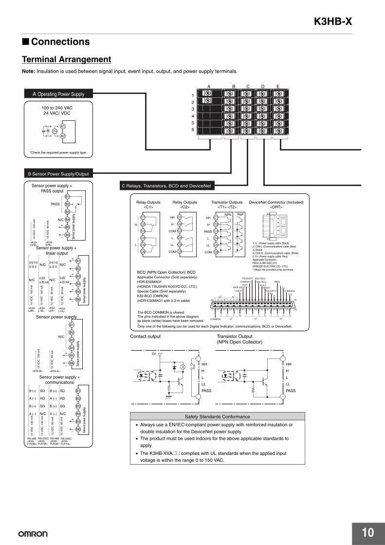
Connections
Terminal ArrangementNote: Insulation is used between signal input, event input, output, and power supply terminals.
B1
B2
B3
B4
B5
B6
B1
B2
B3
B4
B5
B6
B1
B2
B3
B4
B5
B6
+
−
+
−
SD
RD
SG
N/C
B (+)
A (−)
B (+)
A (−)
B (+)
A (−)
B (+)
A (−)
SD
RD
SG
N/C
0-20/4-20 mA
N/CN/C
0-5/1-5/0-10 V
N/CN/C0-5/1-5/0-10 V
+
−+
−+
−
N/C
+
−
PASS
N/C
B1
B2
B3
B4
B5
B6
A B C D E
1
2
3
4
5
6
A Operating Power Supply
B Sensor Power Supply/Output
C Relays, Transistors, BCD and DeviceNet
A1
A2
5V
HH
H
L
LL
PASS
HH
H
L
LL
PASS
Contact output Transistor Output(NPN Open Collector)
• Always use a EN/IEC-compliant power supply with reinforced insulation or
double insulation for the DeviceNet power supply.
• The product must be used indoors for the above applicable standards to
apply.
Safety Standards Conformance
100 to 240 VAC24 VAC/ VDC
*Check the required power supply type.
12 V
DC
80
mA
12 V
DC
80
mA
10 V
DC
100
mA
10 V
DC
100
mA
12 V
DC
80
mA
10 V
DC
100
mA
12 V
DC
80
mA
10 V
DC
100
mA
Sensor power supply + PASS output
Sensor power supply + linear output
12 V
DC
80
mA
12 V
DC
80
mA
10 V
DC
100
mA
10 V
DC
100
mA
Sensor power supply + communications
Sens
or p
ower
sup
ply
Sensor power supply
<K33-CPB>
<K33-CPA>
<K33-B> <K33-A>
<K33-L2B>
<K33-L1B>
<K33-L2A>
<K33-L1A>
RS-485<K33-FLK3B>
RS-232C<K33-FLK1B>
RS-485<K33-FLK3A>
RS-232C<K33-FLK1A>
Sens
or p
ower
sup
ply
Sens
or p
ower
sup
ply
Sens
or p
ower
sup
ply
0-20/4-20 mA
• The K3HB-XVA@@ complies with UL standards when the applied input
voltage is within the range 0 to 150 VAC.
The BCD COMMON is shared.The pins indicated in the above diagram as blank (white) boxes have been removed.*Only one of the following can be used for each Digital Indicator: communications, BCD, or DeviceNet.
DeviceNet Connector (Included)<DRT>
1
2
3
4
5
Relay Outputs<C2>
Relay Outputs<C1>
Transistor Outputs<T1> <T2>
NPN PNPHH
H
PASS
L
LL
COM
C1
C2
C3
C4
C5
C6
HH
H
COM
L
H
L LL
COM
C1
C2
C3
C4
C5
C6
C1
C2
C3
C4
C5
C6
BCD (NPN Open Collector): BCDApplicable Connector (Sold separately)HDR-E50MAG1(HONDA TSUSHIN KOGYO CO., LTD.)Special Cable (Sold separately)K32-BCD (OMRON)(HDR-E50MAG1 with 0.3-m cable)
1: V− (Power supply cable: Black) 2: CAN L (Communications cable: Blue) 3: Shield 4: CAN H (Communications cable: White) 5: V+ (Power supply cable: Red) Applicable Connector: HR31-5.08P-5SC (01) (HIROSE ELECTRIC CO., LTD.) * Attach the provided crimp terminals.

K3HB-X
11
BCD Output Cable
Note: The BCD Output Cable has a D-sub plug. Cover: 17JE-37H-1A (manufactured by DDK); Connector: equivalent to 17JE-23370-02 (D1) (manufactured by DDK)
Special Cable (for Event Inputs with 8-pin Connector)
Model Shape Pin arrangement
K32-BCD
Model Appearance Wiring
K32-DICN
+
-
1: TIMING3: HOLD5: ZERO7: BANK49: BANK1
2: S-TMR4: RESET6: COM8: BANK210: COM
ZERO
COM
RESET
HOLD
S-TMR
TIMINGD1
D2
D3
D4
D5
D6
2
10
1
9
Process IndicatorK3HB-X
Weighing IndicatorK3HB-V
Temperature IndicatorK3HB-H
Linear Sensor IndicatorK3HB-S
AC voltage only
N/C
A
B
C
D
COM
N/C
C
D
N/C
COM
E3
E2
E1
E6
E5
E4
A, B N/C
A
B
C
D
COM COMTC
A
B
B'
Pt
E3
E2
E1
E6
E5
E4
E3
E2
E1
E6
E5
E4
E3
E2
E1
E6
E5
E4
Input B
Current input
Voltage input
Input A
COM
Input A
Input B
N/C
N/C
• Use terminal pin D6 as the common terminal.
• Use NPN open collector or no-voltage contacts for event input.
PNP types are also available.
E Analog Input
D Event Input
D6
3.9 kΩ
4.7 kΩ
S-TMR: D2HOLD: D3
RESET: D4ZERO: D5
12 V
COMD6
D1750 Ω
560 ΩTIMING
12 V
COM
Models with Terminal Blocks<K35-1><K35-3>
Models with Connectors <K35-2><K35-4>
• Applicable Connector (Sold separately) XG4M-1030 (OMRON) • Special Cable (Sold separately) K32-DICN (OMRON) (XG4M-1030 with 3 m cable)
38 mm 46.5 mm300 mm
K3HB endConnected device end
(PLC, display device, etc.)
Cover: HDR-E50LPA5 (manufactured by Honda Tsushin Co., Ltd.)Connector: HDR-E50MAG1 (manufactured by Honda Tsushin Co., Ltd.)
D-sub connector (37-pin female)Cover: 17JE-37H-1A (manufactured by DDK)Connector: Equivalent to 17JE-13370-02 (manufactured by DDK) Stand: 17L-002A (manufactured by DDK)
1
2
3
4
5
6
7
20
21
22
23
24
25
26
27
28
29
30
31
32
33
34
35
36
37
100
101
102
103
104
104
OVERDATA VALIDRUNCOMMONREQUESTMAX REQ.MIN REQ.HOLDRESETPOLARITYHHHPASSL LLCOMMON1
2
48
12
48
12
48
12
48
12
COMMON 48
7
8
9
10
11
12
13
14
15
16
17
18
19
3,000 mm(3 m)Cable marking
9 10
1 2
Pin No.
1
2
3
4
5
6
7
8
9
10
Signal name
N/C
S-TMR
HOLD
RESET
N/C
COM
BANK4
BANK2
BANK1
COM

K3HB-X
12
Main FunctionsMeasurement
Normal• Continuously performs measurement and always outputs based on
comparative results.
Peak Hold/Bottom Hold• Measures the maximum (or minimum) value in a specified period.
Sampling Hold• Holds the measurement at the rising edge of the TIMING signal.
Peak-to-peak Hold• Measures the difference between the maximum and minimum val-
ues in a specified period.
Scaling converts input signals in any way required before displayingthem. The values can be manipulated by shifting, inverting, or +/–reversing.
Settings for scaling can be made using the present measurementvalues instead of inputting values with the SHIFT and UP Keys. Thisis a convenient function for making the settings while monitoring theoperating status.
Turns the comparative output OFF until the measurement valueenters the PASS range.
Average processing of input signals with extreme changes or noisesmooths out the display and makes control stable.
Slight changes can be removed from input signals to detect onlyextreme changes.
Timing Hold
H output
H comparative set value
Input
Time
Measurement value
OFF
ONTIMINGinput
Measurement value
Input
Time
Bottom hold value
Peak hold value
TIMINGinput
Input
Time
OFFON
Sampling hold value
Measurement value
OFFONTIMING
input
Measurement value
Input
Time
Peak-to-peak value
(b2−a2)(b1−a1)
'b2'a2a1
b1
Scaling Average Processing
Teaching
Standby Sequence
Display value 2(dsp.a2)
Display value
Display value 1(dsp.a1)
Input value 1(inp.a1)
Input value 2(inp.a2)
Display value 2(dsp.a2)
Display value
Display value 1(dsp.a1)
Input value 1(inp.a1)
Input value 2(inp.a2) Input value Input value
(Scaling) (Reverse scaling)
Previous Average Value Comparison

K3HB-X
13
Input Compensation/Display
Forces the present value to 0. (Convenient for setting reference val-ues or deducting tares for weight measurement.)
Compensates for mild fluctuations in input signals due to factorssuch as sensor temperature drift, based on OK (PASS) data at mea-surement. (This function can be used with sampling hold, peak hold,or bottom hold.)
Changes the display value to 0 for input values less than the setvalue. It is enabled in normal mode only. (This function can be used,for example, to stop negative values being displayed or to eliminateflickering and minor inconsistencies near 0.)
The display refresh period can be lengthened to reduce flickeringand thereby make the display easier to read.
Values can be displayed in either red or green. With comparative out-put models, the display color can also be set to change according tothe status of comparative outputs (e.g., green to red or red to green).
The current display value can be selected from the present value, the maximum value, and the minimum value.
It is possible to specify (i.e., restrict) the values that the smallest dis-played digit can change by. For example, if the setting is 2, the small-est digit will only take the values 0, 2, 4, 6, or 8 and if the setting is 5,it will only take the values 0 or 5. If the setting is 10, it will only takethe value of 0.
• The minimum and maximum values when the power supply is turned OFF can be saved if interruption memory is turned ON.
• If interruption memory is ON, the maximum and minimum values after the last resetting will be displayed.
• If interruption memory is OFF, the maximum and minimum values will be displayed after the power supply is turned ON (or after the reset input is performed).
Forced-zero
Zero-trimming
Zero-limit
Display Refresh Period
Display Color Selection
Zero-limitsetting
Display
Input
110.01
Red
Red
Comparative set value L
Comparative set value H110.00
100.05110.00
99.87110.00
L
Example) Setting: grn-r
H
P
Green
Display Value Selection
Step Value
Interruption Memory

K3HB-X
14
Output
The output pattern for comparative outputs can be selected. In addi-tion to high/low comparison with set values, output based on levelchanges is also possible. (Use the type of output pattern appropriatefor the application.)
Reverses the output operation of comparative outputs for compara-tive results.
Prevents comparative output chattering when the measurementvalue fluctuates slightly near the set value.
Measurement can be stopped for a set time using external input.
When S-TMR and COM are interconnected and the startup compen-sation timer is set, measurement will not be performed until a settime after the power supply is tuned ON.
Comparative results other than PASS and error signals can be outputfrom the PASS output terminal.
Dimensions
Comparative Output Pattern
Output Logic
ONOFF
ONOFF
ONOFF
Standard Output
Zone Output
Comparativeset value HHComparativeset value HComparativeset value LComparativeset value LL
Measurementvalue
Higher
Lower
Output HH
Output PASS
Output H
Output L
Output LL
Measurementvalue
Higher
Lower
Measurementvalue
Higher
Lower
Comparativeset value HHComparativeset value HComparativeset value LComparativeset value LL
Output HH
Output PASS
Output H
Output L
Output LL
Comparativeset value HHComparativeset value HComparativeset value LComparativeset value LL
Output HH
Output PASS
Output H
Output L
Output LL
Level Output
Hysteresis
Startup Compensation Timer
PASS Output Change
Example: Comparative Output Pattern (Standard Output)
Comparative set value HHysteresis
Hysteresis
Comparative set value L
Comparative output L
Comparative output H
Input
H comparative set value
H output
H input
Time
Startup compensation time set time
Terminal cover (included)
14.2 4.9
3.57.6
96
48
1.312
(112)
100
101.291
95*2
44.8
120 min.
45+0.6 0
92+0.8 0
75 min.
Character Size for Main Display (mm)PV display SV display
*DeviceNet models: 97 mmTerminal: M3, Terminal Cover: Accessory
Panel Cutout Dimensions
K3HB-X
15
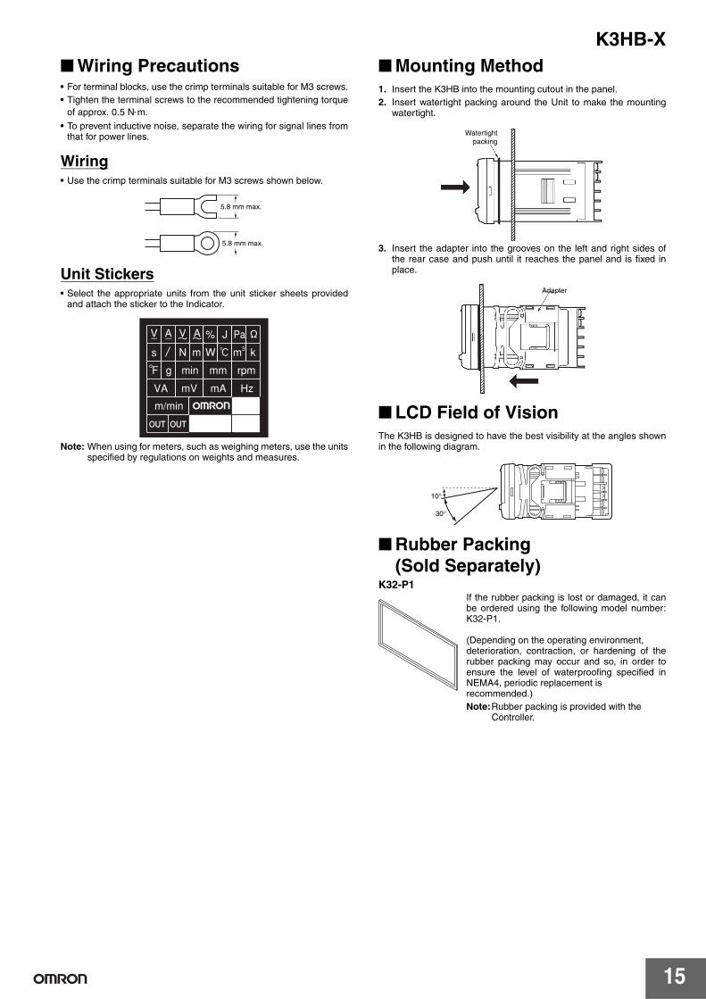
Wiring Precautions• For terminal blocks, use the crimp terminals suitable for M3 screws.• Tighten the terminal screws to the recommended tightening torque
of approx. 0.5 N⋅m.
• To prevent inductive noise, separate the wiring for signal lines fromthat for power lines.
Wiring• Use the crimp terminals suitable for M3 screws shown below.
Unit Stickers• Select the appropriate units from the unit sticker sheets provided
and attach the sticker to the Indicator.
Note: When using for meters, such as weighing meters, use the unitsspecified by regulations on weights and measures.
Mounting Method1. Insert the K3HB into the mounting cutout in the panel.2. Insert watertight packing around the Unit to make the mounting
watertight.
3. Insert the adapter into the grooves on the left and right sides ofthe rear case and push until it reaches the panel and is fixed inplace.
LCD Field of VisionThe K3HB is designed to have the best visibility at the angles shownin the following diagram.
Rubber Packing (Sold Separately)
K32-P1If the rubber packing is lost or damaged, it canbe ordered using the following model number:K32-P1.
(Depending on the operating environment, deterioration, contraction, or hardening of therubber packing may occur and so, in order toensure the level of waterproofing specified inNEMA4, periodic replacement is recommended.)Note:Rubber packing is provided with the
Controller.
5.8 mm max.
5.8 mm max.
Watertightpacking
Adapter
10°
30°
K3HB-X
16
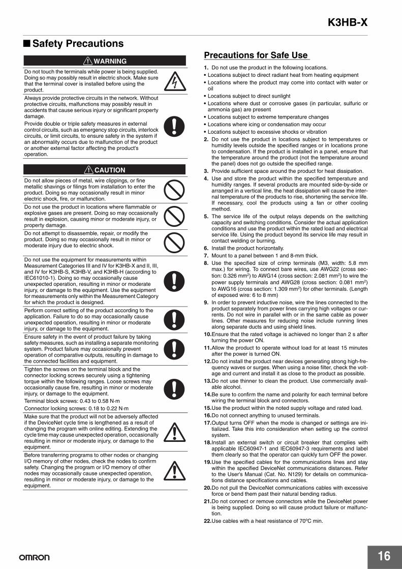
Safety Precautions
!WARNING
!CAUTION
Precautions for Safe Use 1. Do not use the product in the following locations.• Locations subject to direct radiant heat from heating equipment• Locations where the product may come into contact with water or
oil• Locations subject to direct sunlight• Locations where dust or corrosive gases (in particular, sulfuric or
ammonia gas) are present• Locations subject to extreme temperature changes• Locations where icing or condensation may occur• Locations subject to excessive shocks or vibration2. Do not use the product in locations subject to temperatures or
humidity levels outside the specified ranges or in locations proneto condensation. If the product is installed in a panel, ensure thatthe temperature around the product (not the temperature aroundthe panel) does not go outside the specified range.
3. Provide sufficient space around the product for heat dissipation.4. Use and store the product within the specified temperature and
humidity ranges. If several products are mounted side-by-side orarranged in a vertical line, the heat dissipation will cause the inter-nal temperature of the products to rise, shortening the service life.If necessary, cool the products using a fan or other coolingmethod.
5. The service life of the output relays depends on the switchingcapacity and switching conditions. Consider the actual applicationconditions and use the product within the rated load and electricalservice life. Using the product beyond its service life may result incontact welding or burning.
6. Install the product horizontally.7. Mount to a panel between 1 and 8-mm thick.8. Use the specified size of crimp terminals (M3, width: 5.8 mm
max.) for wiring. To connect bare wires, use AWG22 (cross sec-tion: 0.326 mm2) to AWG14 (cross section: 2.081 mm2) to wire thepower supply terminals and AWG28 (cross section: 0.081 mm2)to AWG16 (cross section: 1.309 mm2) for other terminals. (Lengthof exposed wire: 6 to 8 mm)
9. In order to prevent inductive noise, wire the lines connected to theproduct separately from power lines carrying high voltages or cur-rents. Do not wire in parallel with or in the same cable as powerlines. Other measures for reducing noise include running linesalong separate ducts and using shield lines.
10.Ensure that the rated voltage is achieved no longer than 2 s afterturning the power ON.
11.Allow the product to operate without load for at least 15 minutesafter the power is turned ON.
12.Do not install the product near devices generating strong high-fre-quency waves or surges. When using a noise filter, check the volt-age and current and install it as close to the product as possible.
13.Do not use thinner to clean the product. Use commercially avail-able alcohol.
14.Be sure to confirm the name and polarity for each terminal beforewiring the terminal block and connectors.
15.Use the product within the noted supply voltage and rated load.16.Do not connect anything to unused terminals. 17.Output turns OFF when the mode is changed or settings are ini-
tialized. Take this into consideration when setting up the controlsystem.
18.Install an external switch or circuit breaker that complies withapplicable IEC60947-1 and IEC60947-3 requirements and labelthem clearly so that the operator can quickly turn OFF the power.
19.Use the specified cables for the communications lines and staywithin the specified DeviceNet communications distances. Referto the User's Manual (Cat. No. N129) for details on communica-tions distance specifications and cables.
20.Do not pull the DeviceNet communications cables with excessiveforce or bend them past their natural bending radius.
21.Do not connect or remove connectors while the DeviceNet poweris being supplied. Doing so will cause product failure or malfunc-tion.
22.Use cables with a heat resistance of 70ºC min.
Do not touch the terminals while power is being supplied. Doing so may possibly result in electric shock. Make sure that the terminal cover is installed before using the product.
Always provide protective circuits in the network. Without protective circuits, malfunctions may possibly result in accidents that cause serious injury or significant property damage.Provide double or triple safety measures in external control circuits, such as emergency stop circuits, interlock circuits, or limit circuits, to ensure safety in the system if an abnormality occurs due to malfunction of the product or another external factor affecting the product's operation.
Do not allow pieces of metal, wire clippings, or fine metallic shavings or filings from installation to enter the product. Doing so may occasionally result in minor electric shock, fire, or malfunction.
Do not use the product in locations where flammable or explosive gases are present. Doing so may occasionally result in explosion, causing minor or moderate injury, or property damage.
Do not attempt to disassemble, repair, or modify the product. Doing so may occasionally result in minor or moderate injury due to electric shock.
Do not use the equipment for measurements within Measurement Categories III and IV for K3HB-X and II, III, and IV for K3HB-S, K3HB-V, and K3HB-H (according to IEC61010-1). Doing so may occasionally cause unexpected operation, resulting in minor or moderate injury, or damage to the equipment. Use the equipment for measurements only within the Measurement Category for which the product is designed.
Perform correct setting of the product according to the application. Failure to do so may occasionally cause unexpected operation, resulting in minor or moderate injury, or damage to the equipment.
Ensure safety in the event of product failure by taking safety measures, such as installing a separate monitoring system. Product failure may occasionally prevent operation of comparative outputs, resulting in damage to the connected facilities and equipment.
Tighten the screws on the terminal block and the connector locking screws securely using a tightening torque within the following ranges. Loose screws may occasionally cause fire, resulting in minor or moderate injury, or damage to the equipment.Terminal block screws: 0.43 to 0.58 N·m Connector locking screws: 0.18 to 0.22 N·m
Make sure that the product will not be adversely affected if the DeviceNet cycle time is lengthened as a result of changing the program with online editing. Extending the cycle time may cause unexpected operation, occasionally resulting in minor or moderate injury, or damage to the equipment.
Before transferring programs to other nodes or changing I/O memory of other nodes, check the nodes to confirm safety. Changing the program or I/O memory of other nodes may occasionally cause unexpected operation, resulting in minor or moderate injury, or damage to the equipment.

K3HB-X
17
Noise Countermeasures1. Do not install the product near devices generating strong high-fre-
quency waves or surges, such as high-frequency welding andsewing machines.
2. Mount a surge suppressor or noise filter to peripheral devicesgenerating noise, in particular, motors, transformers, solenoids,and magnet coils.
3. In order to prevent inductive noise, wire the lines connected to theterminal block separately from power lines carrying high voltagesor currents. Do not wire in parallel with or in the same cable aspower lines. Other measures for reducing noise include runninglines along separate ducts and using shield lines.
Example of Countermeasures for Inductive Noise on Input Lines
4. If a noise filter is used for the power supply, check the voltage andcurrent, and install the noise filter as close to the product as pos-sible.
5. Reception interference may occur if the product is used close to aradio, television, or wireless.
+
-
Digital Indicator
Line filter
Surge suppressor
Pow
er s
uppl
y in
put
Sig
nal i
nput
Pow
er s
uppl
y in
put
Digital Indicator
+
-
Signal input
2 conductors with shield
Digital Indicator
In the interest of product improvement, specifications are subject to change without notice.
ALL DIMENSIONS SHOWN ARE IN MILLIMETERS.
To convert millimeters into inches, multiply by 0.03937. To convert grams into ounces, multiply by 0.03527.
Read and Understand This Catalog Please read and understand this catalog before purchasing the products. Please consult your OMRON representative if you have any questions or comments.
Warranty and Limitations of Liability WARRANTY OMRON's exclusive warranty is that the products are free from defects in materials and workmanship for a period of one year (or other period if specified) from date of sale by OMRON. OMRON MAKES NO WARRANTY OR REPRESENTATION, EXPRESS OR IMPLIED, REGARDING NON-INFRINGEMENT, MERCHANTABILITY, OR FITNESS FOR PARTICULAR PURPOSE OF THE PRODUCTS. ANY BUYER OR USER ACKNOWLEDGES THAT THE BUYER OR USER ALONE HAS DETERMINED THAT THE PRODUCTS WILL SUITABLY MEET THE REQUIREMENTS OF THEIR INTENDED USE. OMRON DISCLAIMS ALL OTHER WARRANTIES, EXPRESS OR IMPLIED. LIMITATIONS OF LIABILITY OMRON SHALL NOT BE RESPONSIBLE FOR SPECIAL, INDIRECT, OR CONSEQUENTIAL DAMAGES, LOSS OF PROFITS OR COMMERCIAL LOSS IN ANY WAY CONNECTED WITH THE PRODUCTS, WHETHER SUCH CLAIM IS BASED ON CONTRACT, WARRANTY, NEGLIGENCE, OR STRICT LIABILITY. In no event shall the responsibility of OMRON for any act exceed the individual price of the product on which liability is asserted. IN NO EVENT SHALL OMRON BE RESPONSIBLE FOR WARRANTY, REPAIR, OR OTHER CLAIMS REGARDING THE PRODUCTS UNLESS OMRON'S ANALYSIS CONFIRMS THAT THE PRODUCTS WERE PROPERLY HANDLED, STORED, INSTALLED, AND MAINTAINED AND NOT SUBJECT TO CONTAMINATION, ABUSE, MISUSE, OR INAPPROPRIATE MODIFICATION OR REPAIR.
Application Considerations SUITABILITY FOR USE OMRON shall not be responsible for conformity with any standards, codes, or regulations that apply to the combination of products in the customer's application or use of the products. At the customer's request, OMRON will provide applicable third party certification documents identifying ratings and limitations of use that apply to the products. This information by itself is not sufficient for a complete determination of the suitability of the products in combination with the end product, machine, system, or other application or use. The following are some examples of applications for which particular attention must be given. This is not intended to be an exhaustive list of all possible uses of the products, nor is it intended to imply that the uses listed may be suitable for the products:
• Outdoor use, uses involving potential chemical contamination or electrical interference, or conditions or uses not described in this catalog. • Nuclear energy control systems, combustion systems, railroad systems, aviation systems, medical equipment, amusement machines, vehicles,
safety equipment, and installations subject to separate industry or government regulations. • Systems, machines, and equipment that could present a risk to life or property.
Please know and observe all prohibitions of use applicable to the products. NEVER USE THE PRODUCTS FOR AN APPLICATION INVOLVING SERIOUS RISK TO LIFE OR PROPERTY WITHOUT ENSURING THAT THE SYSTEM AS A WHOLE HAS BEEN DESIGNED TO ADDRESS THE RISKS, AND THAT THE OMRON PRODUCTS ARE PROPERLY RATED AND INSTALLED FOR THE INTENDED USE WITHIN THE OVERALL EQUIPMENT OR SYSTEM. PROGRAMMABLE PRODUCTS OMRON shall not be responsible for the user's programming of a programmable product, or any consequence thereof.
Disclaimers CHANGE IN SPECIFICATIONS Product specifications and accessories may be changed at any time based on improvements and other reasons. It is our practice to change model numbers when published ratings or features are changed, or when significant construction changes are made. However, some specifications of the products may be changed without any notice. When in doubt, special model numbers may be assigned to fix or establish key specifications for your application on your request. Please consult with your OMRON representative at any time to confirm actual specifications of purchased products. DIMENSIONS AND WEIGHTS Dimensions and weights are nominal and are not to be used for manufacturing purposes, even when tolerances are shown. PERFORMANCE DATA Performance data given in this catalog is provided as a guide for the user in determining suitability and does not constitute a warranty. It may represent the result of OMRON’s test conditions, and the users must correlate it to actual application requirements. Actual performance is subject to the OMRON Warranty and Limitations of Liability. ERRORS AND OMISSIONS The information in this document has been carefully checked and is believed to be accurate; however, no responsibility is assumed for clerical, typographical, or proofreading errors, or omissions.
2008.11
In the interest of product improvement, specifications are subject to change without notice.
OMRON Corporation Industrial Automation Company http://www.ia.omron.com/
(c)Copyright OMRON Corporation 2008 All Right Reserved.