Process Development of High-k Metal Gate Aluminum CMP at ...
28
Process Development of High-k Metal Gate Aluminum CMP at 28nm Technology Node UMC/ ATD_AM / CMP Department Y. H. Hsieh , H. K. Hsu, R. P. Huang, C. H. Chen, T. C. Tsai, Welch Lin, C. L. Yang and J. Y. Wu
Transcript of Process Development of High-k Metal Gate Aluminum CMP at ...
Process Development of High-k Metal Gate Aluminum CMP at 28nm
Technology Node
UMC/ ATD_AM / CMP Department
Y. H. Hsieh, H. K. Hsu, R. P. Huang, C. H. Chen, T. C. Tsai, Welch Lin, C. L. Yang and J. Y. Wu

2
Introduction
3
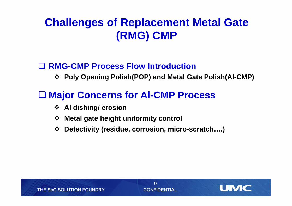
qRMG-CMP Process Flow Introductionv Poly Opening Polish(POP) and Metal Gate Polish(Al-CMP)
q Major Concerns for Al-CMP Processv Al dishing/ erosion
v Metal gate height uniformity control
v Defectivity (residue, corrosion, micro-scratch….)
Challenges of Replacement Metal Gate (RMG) CMP

4
Pre-Poly Opening Polish (POP) Structure
CESL SIN SP2 Poly ILD OX
SP1
Poly Hard Mask
STI STISTIIL/HKSiGe SiGe
NMOS PMOS
HM
PolyPoly
HM
ILD OX
STISi
CESL
ILD OX
q Process challenge is the thickness optimization of ILD OX, Poly HM and CESL films.
5
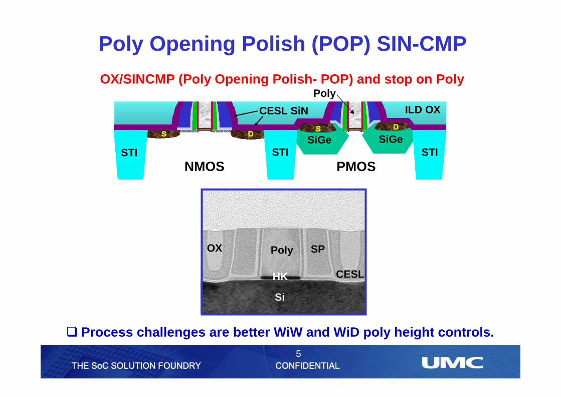
q Process challenges are better WiW and WiD poly height controls.
OX/SINCMP (Poly Opening Polish- POP) and stop on Poly
NMOS PMOSSTI STISTI
SiGe SiGe
CESL SiN ILD OX
Poly
Poly SP
Si
HK
OX
CESL
Poly Opening Polish (POP) SIN-CMP
6
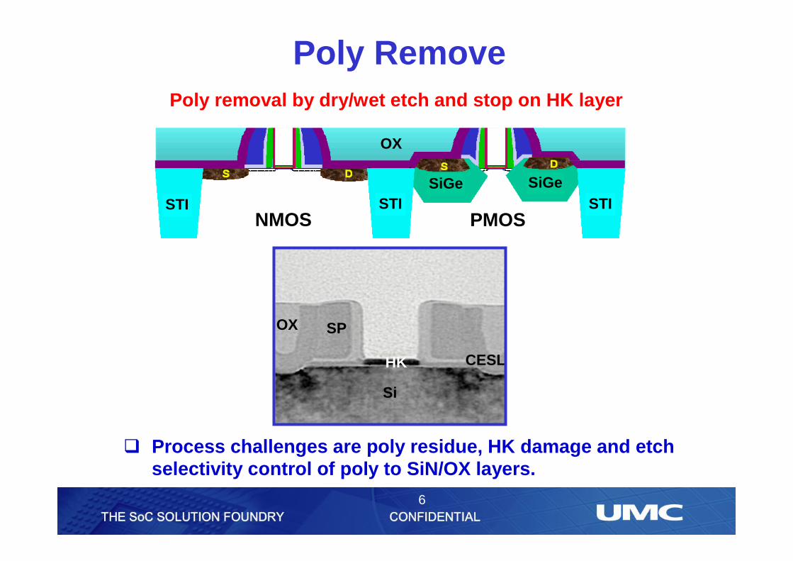
Poly Remove
q Process challenges are poly residue, HK damage and etch selectivity control of poly to SiN/OX layers.
Poly removal by dry/wet etch and stop on HK layer
OX
CESL
SP
Si
NMOS PMOSSTI STISTI
SiGe SiGe
OX
HK
7
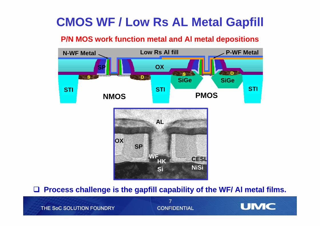
q Process challenge is the gapfill capability of the WF/ Al metal films.
CMOS WF / Low Rs AL Metal Gapfill
N-WF Metal Low Rs Al fill P-WF Metal
SP
STI STISTI
SiGe SiGe
NMOS PMOS
P/N MOS work function metal and Al metal depositions
OX
AL
OX
CESL
Si
SP
NiSiHK
WF
8
W
Si
NiSi
ILD (OX)
SiCN
STI STISTI
SiGe SiGe
NMOS PMOS
N-WF Metal
Al
P-WF Metal
Al
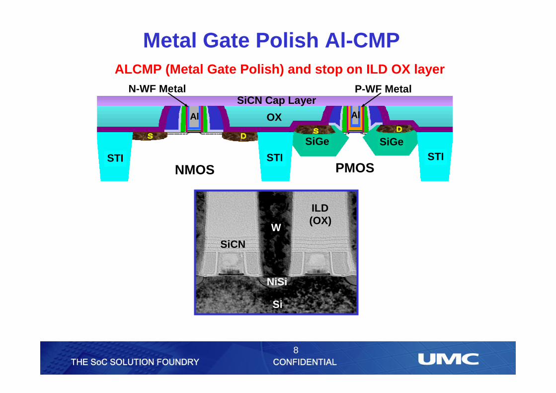
Metal Gate Polish Al-CMP ALCMP (Metal Gate Polish) and stop on ILD OX layer
SiCN Cap Layer
OX
9
q RMG-CMP Process Flow Introductionv Poly Opening Polish(POP) and Metal Gate Polish(Al-CMP)
qMajor Concerns for Al-CMP Processv Al dishing/ erosion
v Metal gate height uniformity control
v Defectivity (residue, corrosion, micro-scratch….)
Challenges of Replacement Metal Gate (RMG) CMP
10
Experimental
11
q 300mm blanket wafers with Al metal layer/ ILD oxide layer/ Si-substrate were prepared to obtain the uniformity control performance post Al-CMP.
q The pattern wafers were constructed with PVD hot Al film/ CVD Al seed/ work function metal layers to obtain the metal gate height loss, Al dishing and defectivityperformance.
q The Al-CMP process was carried out a rotary type polisher with three polishing platens.
Experimental
12
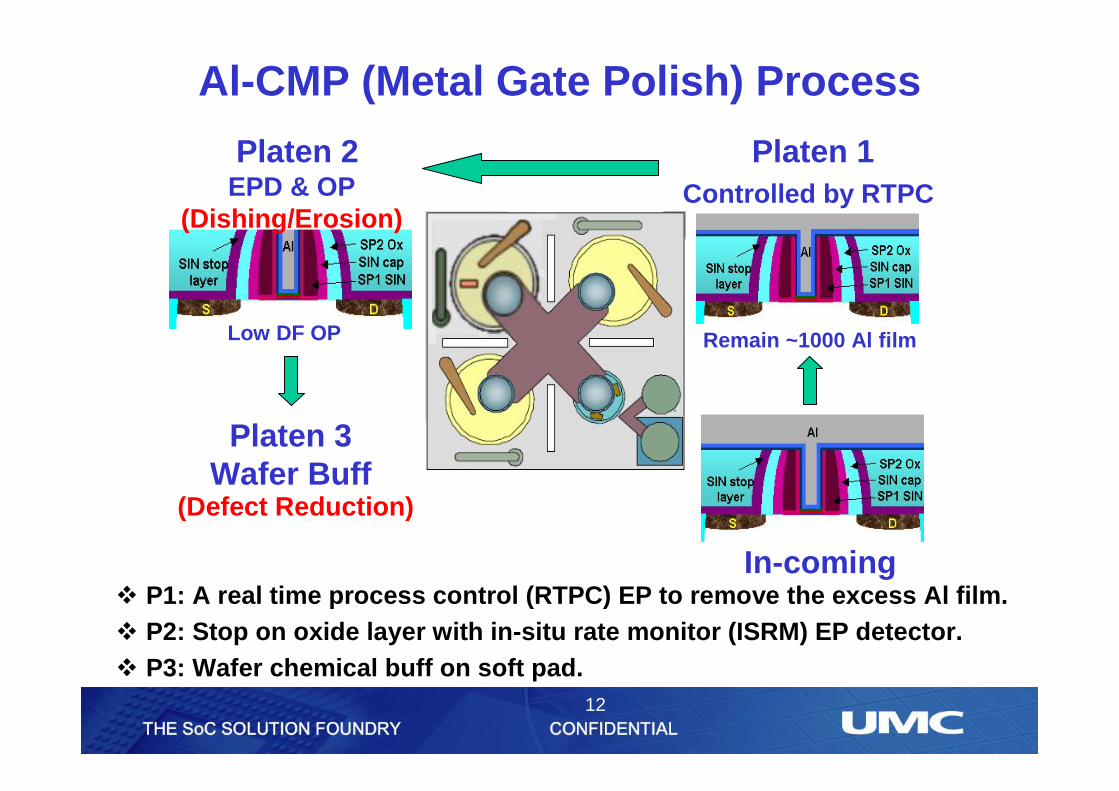
Al-CMP (Metal Gate Polish) Process
In-coming
Platen 1Platen 2Controlled by RTPCEPD & OP
(Dishing/Erosion)
Platen 3Wafer Buff
Remain ~1000 Al filmLow DF OP
(Defect Reduction)
v P1: A real time process control (RTPC) EP to remove the excess Al film. v P2: Stop on oxide layer with in-situ rate monitor (ISRM) EP detector. v P3: Wafer chemical buff on soft pad.

13
q Al thickness on blanket wafers pre- and post Al-CMP was measured by using a KLA RS-100 4 point probe.
q The total metal gate loss and Al dishing were characterized by using high-resolution atomic force profiler (HR-AFP).
q Defect inspection were conducted on KLA-Tencor 2835.
q The clarification of different defect types were determined by using top viewed SEM micrographs.
Experimental
14
Results and Discussion
15
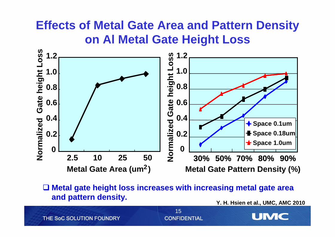
Effects of Metal Gate Area and Pattern Density on Al Metal Gate Height Loss
qMetal gate height loss increases with increasing metal gate areaand pattern density.
No
rmal
ized
Gat
e h
eig
ht
Lo
ss
0
0.2
0.4
0.6
0.8
1.0
1.2
2.5 10 25 50Metal Gate Area (um )2
No
rmal
ized
Gat
e h
eig
ht
Lo
ssMetal Gate Pattern Density (%)
0
0.2
0.4
0.6
0.8
1.0
1.2
30% 50% 70% 80% 90%30% 50% 70% 80% 90%
Space 0.1um
Space 0.18um
Space 1.0um
Y. H. Hsien et al., UMC, AMC 2010
16
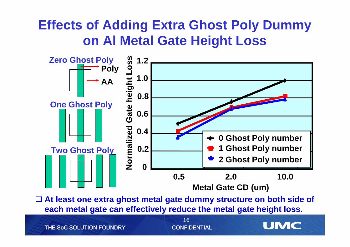
0
0.2
0.4
0.6
0.8
1.0
1.2
0.5 2.0 10.0Metal Gate CD (um)
No
rmal
ized
Gat
e h
eig
ht
Lo
ss0 Ghost Poly number1 Ghost Poly number2 Ghost Poly number
0 Ghost Poly number1 Ghost Poly number2 Ghost Poly number
Poly
AA
Two Ghost Poly
One Ghost Poly
Zero Ghost Poly
Effects of Adding Extra Ghost Poly Dummy on Al Metal Gate Height Loss
q At least one extra ghost metal gate dummy structure on both side of each metal gate can effectively reduce the metal gate height loss.
17
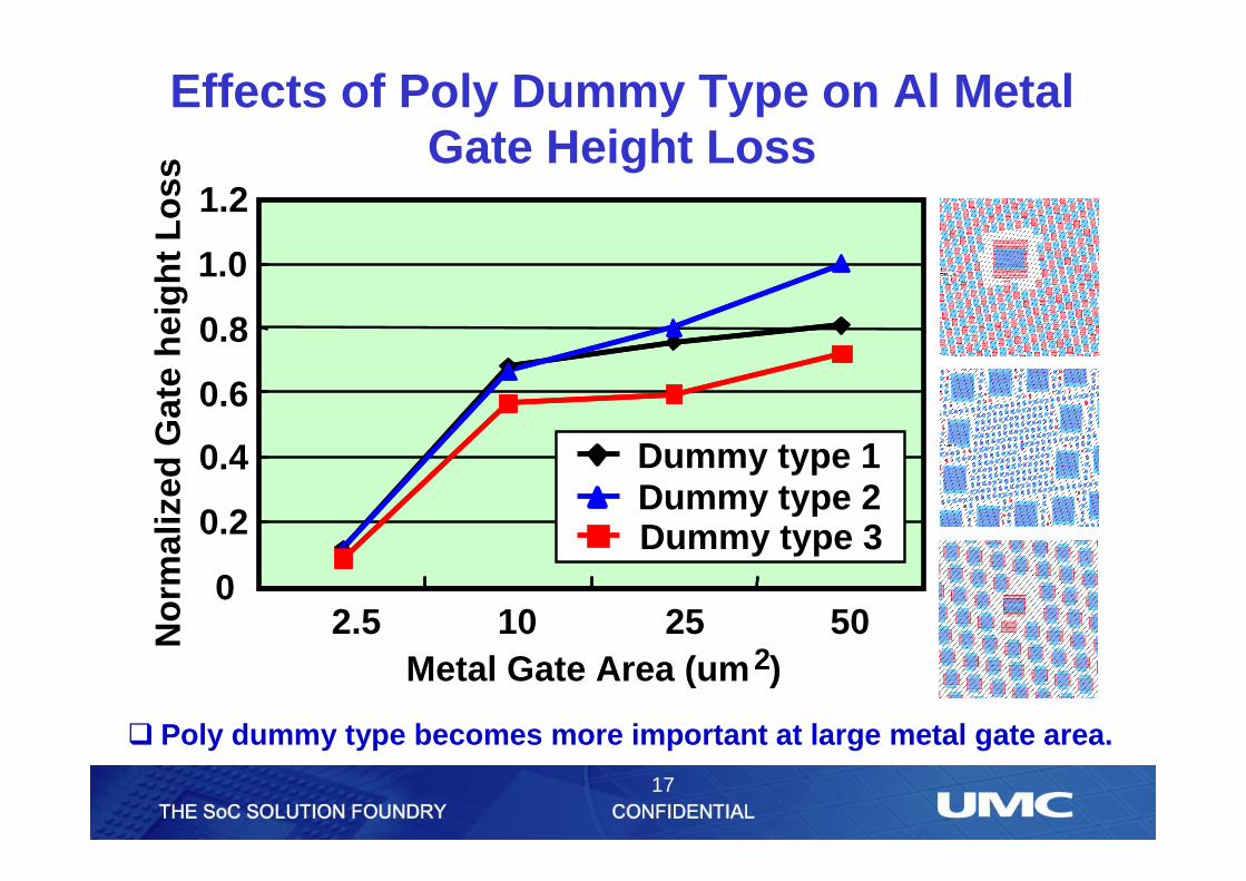
Effects of Poly Dummy Type on Al Metal Gate Height Loss
q Poly dummy type becomes more important at large metal gate area.
No
rmal
ized
Gat
e h
eig
ht
Lo
ss
0
0.2
0.4
0.6
0.8
1.0
1.2
2.5 10 25 502
Dummy type 1Dummy type 2Dummy type 3
Metal Gate Area (um )
18
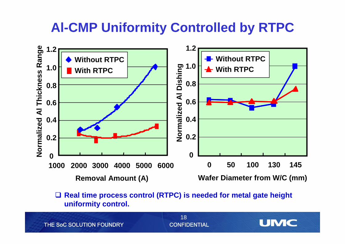
Al-CMP Uniformity Controlled by RTPC
q Real time process control (RTPC) is needed for metal gate heightuniformity control.
No
rmal
ized
Al T
hic
knes
s R
ang
e
0
0.2
0.4
0.6
0.8
1.0
1.2
1000 2000 3000 4000 5000 6000
Removal Amount (A)
Without RTPC
With RTPCWithout RTPC
With RTPC
0
0.2
0.4
0.6
0.8
1.0
1.2
0 50 100 130 145
Wafer Diameter from W/C (mm)N
orm
aliz
ed A
l Dis
hin
g
Without RTPCWith RTPC
19
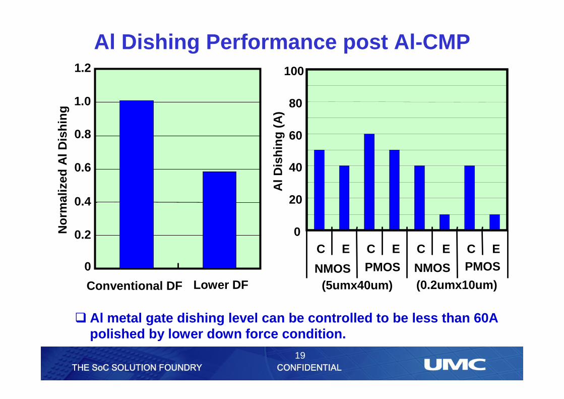
q Al metal gate dishing level can be controlled to be less than 60A polished by lower down force condition.
Al Dishing Performance post Al-CMP
0
0.2
0.4
0.6
0.8
1.0
1.2
Conventional DF Lower DF
No
rmal
ized
Al D
ish
ing
0
20
40
60
80
100
C E C E C E C E
DA03 DB03 OXN2 OXP2(0.2umx10um)(5umx40um)
NMOS PMOS NMOS PMOSA
l Dis
hin
g (
A)
20
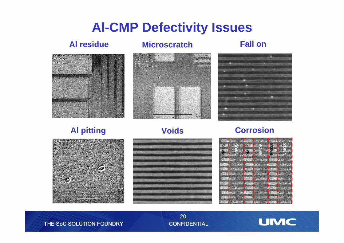
Al-CMP Defectivity Issues Al residue Microscratch
VoidsAl pitting
Fall on
Corrosion
PM
OS
PM
OS
PM
OS
NM
OS
NM
OS
NM
OS
21
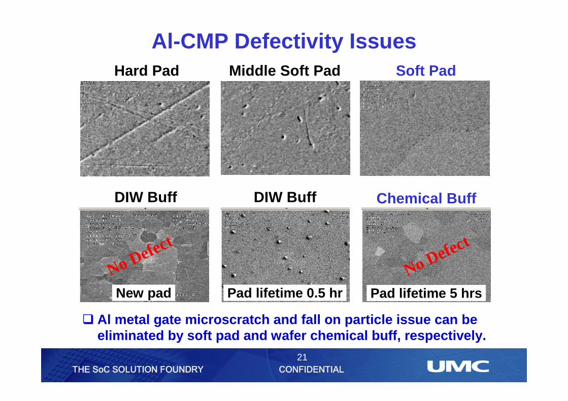
Al-CMP Defectivity Issues Hard Pad Middle Soft Pad Soft Pad
No Defect
No Defect
DIW Buff DIW Buff Chemical Buff
New pad Pad lifetime 0.5 hr Pad lifetime 5 hrs
q Al metal gate microscratch and fall on particle issue can be eliminated by soft pad and wafer chemical buff, respectively.
22
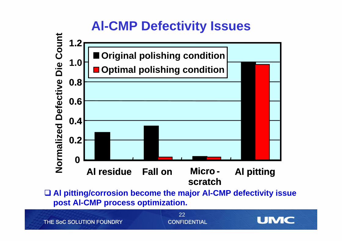
Al-CMP Defectivity Issues
0
0.2
0.4
0.6
0.8
1.0
1.2
Al residue Fall on Micro -scratch
Al pitting No
rmal
ized
Def
ecti
ve D
ie C
ou
nt
Original polishing condition
Optimal polishing condition
0
0.2
0.4
0.6
0.8
1.2
Al residue Fall on Micro -scratch
Al pitting
Original polishing condition
Optimal polishing condition
q Al pitting/corrosion become the major Al-CMP defectivity issue post Al-CMP process optimization.
23
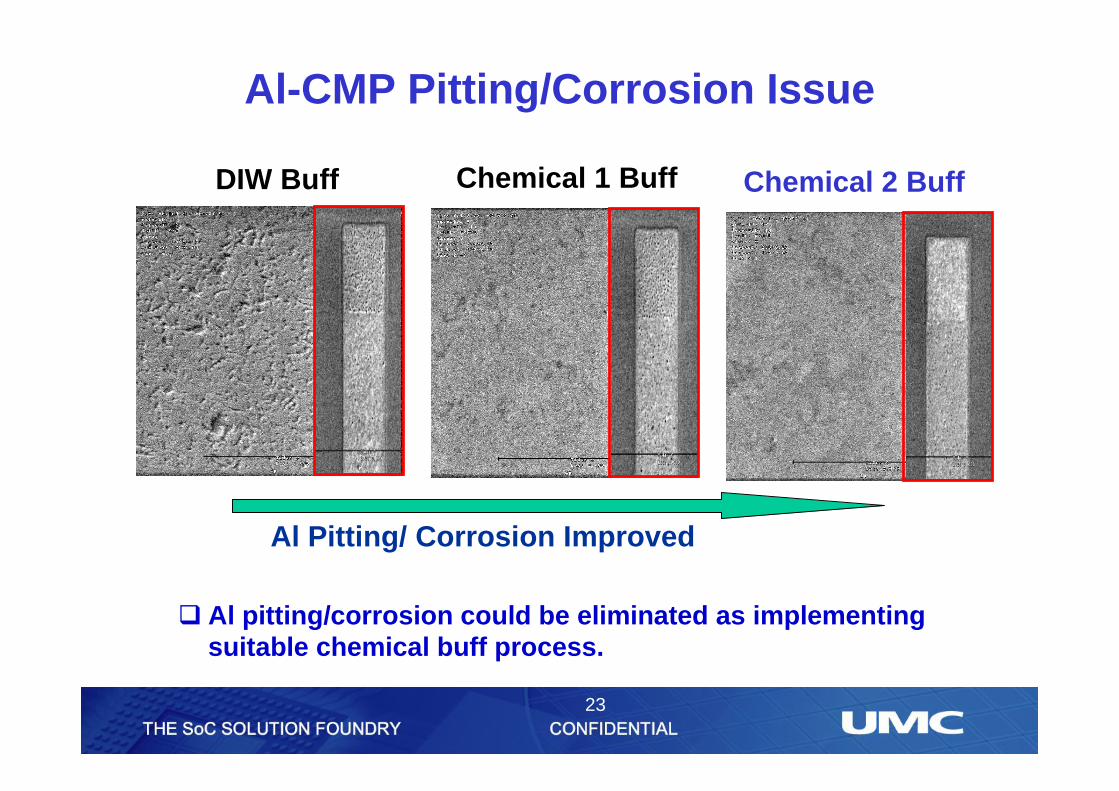
Al-CMP Pitting/Corrosion Issue
DIW Buff Chemical 2 BuffChemical 1 Buff
q Al pitting/corrosion could be eliminated as implementing suitable chemical buff process.
Al Pitting/ Corrosion Improved
24
Conclusions
25
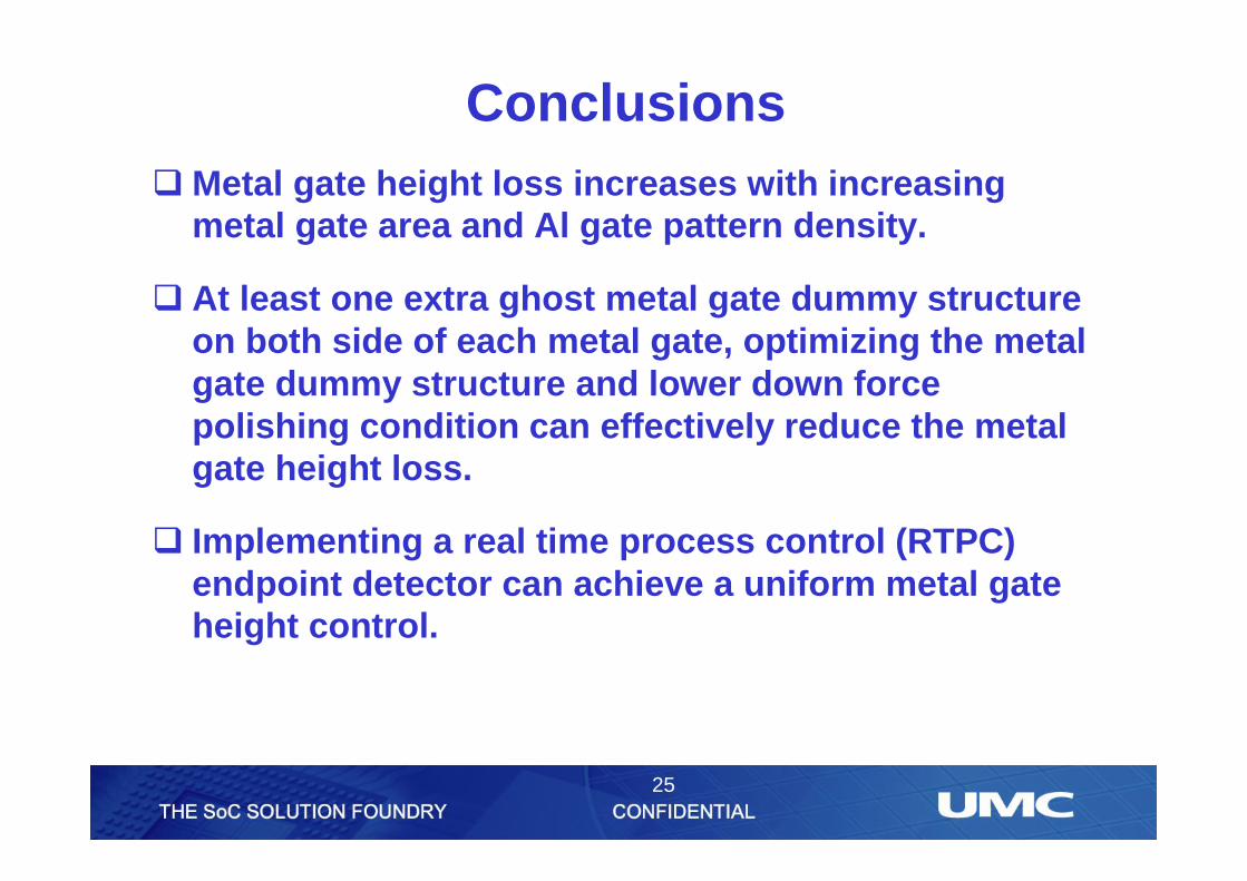
ConclusionsqMetal gate height loss increases with increasing
metal gate area and Al gate pattern density.
q At least one extra ghost metal gate dummy structure on both side of each metal gate, optimizing the metal gate dummy structure and lower down force polishing condition can effectively reduce the metal gate height loss.
q Implementing a real time process control (RTPC) endpoint detector can achieve a uniform metal gate height control.
26
Conclusions
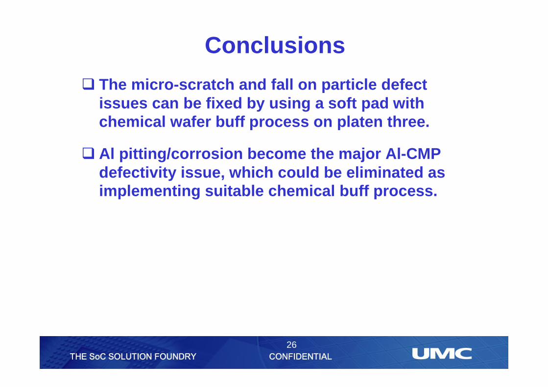
q The micro-scratch and fall on particle defect issues can be fixed by using a soft pad with chemical wafer buff process on platen three.
q Al pitting/corrosion become the major Al-CMP defectivity issue, which could be eliminated as implementing suitable chemical buff process.
27
Thank You!
28
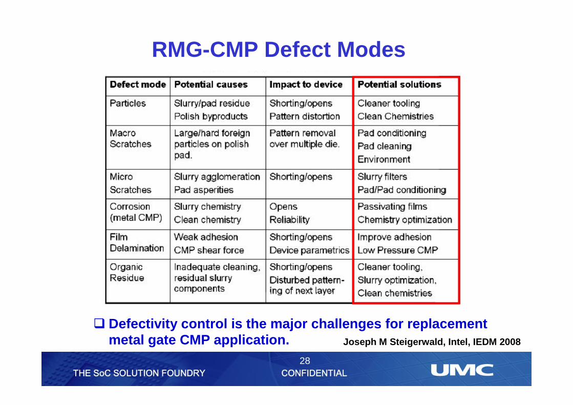
q Defectivity control is the major challenges for replacement metal gate CMP application.
RMG-CMP Defect Modes
Joseph M Steigerwald, Intel, IEDM 2008