PROCESS CONTROL COMPUTERS AT DURGAPUR STEEL PLANTS BASIC OXYGEN FURNACES.
IPS-E-PR-810
This Standard is the property of Iranian Ministry of Petroleum. All rights are reserved to the owner. Neither whole nor any part of this document may be disclosed to any third party, reproduced, stored in any retrieval system or transmitted in any form or by any means without the prior written consent of the Iranian Ministry of Petroleum.
ENGINEERING STANDARD
FOR
PROCESS DESIGN OF FURNACES
ORIGINAL EDITION
DEC. 1997

Dec. 1997
IPS-E-PR-810
1
CONTENTS : PAGE No. 0. INTRODUCTION ............................................................................................................................. 2 1. SCOPE ............................................................................................................................................ 3 2. REFERENCES ................................................................................................................................ 3 3. DEFINITIONS AND TERMINOLOGY ............................................................................................. 4 4. SYMBOLS AND ABBREVIATIONS ............................................................................................... 7 5. UNITS .............................................................................................................................................. 8 6. DESIGN REQUIREMENTS OF FURNACE .................................................................................... 8 ............................................................................................................. 86.1 Design Conditions ............................................................................................................ 96.2 Furnace Turndown ............................................................................................ 96.3 Furnace Outlet Temperature ............................................................................................................ 96.4 Velocity Limitation ................................................................................................................... 96.5 Fouling Factor .................................................................................................................. 106.6 Pressure Drop ............................................................................................................... 106.7 Thermal Design7. FURNACE LAYOUT AND TUBE ARRANGEMENT .................................................................... 11 8. TUBES, TUBE SHEETS, SUPPORTS, HEADERS AND HEADER BOXES............................... 12 9. BURNERS AND FUEL SYSTEM.................................................................................................. 13 10. STRUCTURAL DESIGN ............................................................................................................. 16 11. PLATFORMS, STAIRS AND LADDERS.................................................................................... 16 12. DUCTS AND STACKS ............................................................................................................... 16 13. SOOT BLOWERS ....................................................................................................................... 17 14. FANS AND DRIVERS ................................................................................................................. 18 15. AIR PREHEATER ....................................................................................................................... 18
15.1 Types of Air Preheat Systems ........................................................................................... 18 16. INSTRUMENTATION, INSTRUMENT AND AUXILIARY CONNECTIONS............................... 18
16.1 Instrumentation ................................................................................................................... 18 16.2 Instrument and Auxiliary Connections ............................................................................. 19 16.3 Controls ............................................................................................................................... 19 16.4 Measurements ..................................................................................................................... 19 16.5 Protective Measurement .................................................................................................... 21
17. LIGHTING ................................................................................................................................... 23 18. GUARANTEES ........................................................................................................................... 23 19. REQUIRED INFORMATION/DOCUMENTS............................................................................... 24
19.4 Information Required with the Quotation ......................................................................... 24 19.5 Information Required Against Purchase Order ............................................................... 25
APPENDICES: APPENDIX A ...................................................................... 27TYPICAL FURNACE DATA SHEETa)APPENDIX B ......................... 39FURNACE TUBE SIZE AND PASSES FOR CRUDE HEATER (1)APPENDIX C
.............................. 40TYPICAL PIPING AND INSTRUMENT DIAGRAMS (P & IDs)
FOR CRUDE HEATER AND RELEVANT AIR PREHEATINGAPPENDIX D ............................. 44TYPICAL HEATER PROCESS FLOW SHEET DESIGN CASE
Dec. 1997
IPS-E-PR-810
2
0. INTRODUCTION
"Process Design of Combustion Type Heat Exchanging Equipment" are broad and contain various subjects of paramount importance. Therefore, a group of process engineering standards are prepared to cover the subject of combustion type heat exchanging equipment.
This group includes the following Standards:
STANDARD CODE STANDARD TITLE
IPS-E-PR-800 "Process Design of Steam Boilers"
IPS-E-PR-810 "Process Design of Furnaces"
This Engineering Standard Specification covers:
"PROCESS DESIGN OF FURNACES"
The requirements outlined herein are supplementary to the specifications listed on the individual fired heater data sheets (typical fired heater data sheet is shown in Appendix A).
In the event of a conflict among the various documents, the order of precedence shall be as follows:
Individual fired heater data sheets.
Iranian Petroleum Standards (IPS), Engineering Standard for Process Design of Furnaces, IPS-E-PR-810.
If conflict is discovered between the items listed, it shall be the responsibility of the Vendor to call attention to the conflict.
Approval of Vendor’s drawings shall not relieve the Vendor from this responsibility in performance of the equipment specified herein.
Dec. 1997
IPS-E-PR-810
3
1. SCOPE
This Engineering Standard Specification is intended to cover minimum requirements for process design of furnaces.
The application of this Engineering Standard Specification shall be exercised only in combination with relevant mechanical standard, i.e., IPS-G-ME-200, "Fired Heaters", respectively.
2. REFERENCES
Throughout this Standard the following dated and undated standards/codes are referred to. These referenced documents shall, to the extent specified herein, form a part of this standard. For dated references, the edition cited applies. The applicability of changes in dated references that occur after the cited date shall be mutually agreed upon by the Company and the Vendor. For undated references, the latest edition of the referenced documents (including any supplements and amendments) applies.
API (AMERICAN PETROLEUM INSTITUTE)
API Recommended Practice 533 "Air Preheat Systems for Fired Process Heaters",
1st. Ed., January 1986
API Standard 560 "Fired Heaters for General Refinery Services",
1st. Ed., January 1986
API Standard 602 "Compact Steel Gate Valves", 1985
API Standard 630 "Tube and Header Dimensions for Fired Heaters for Refinery Services",
2nd. Ed. October 1961
ASME (AMERICAN SOCIETY OF MECHANICAL ENGINEERS)
ASME "Power Boiler Code, Section I"
IPS (IRANIAN PETROLEUM STANDARDS)
IPS-G-ME-200 "Fired Heaters"
BSI (BRITISH STANDARDS INSTITUTION)
BS 5410 "Code of Practice for Oil Firing, Part 3: Installation for Furnaces, Kilns, Oven and Other Industrial Purposes", 1976
KENNETH G. OLIVER
"Industrial Boiler Management",
1st. Printing: 1989, Industrial Press Inc. New York
NAFM (NATIONAL ASSOCIATION OF FAN MANUFACTURERS)
Standard Test Code
NIOC (NATIONAL IRANIAN OIL COMPANY)
SP-2219-45-3 "Job Specification for Fired Heaters"
Dec. 1997
IPS-E-PR-810
4
ARAK REFINERY PROJECT
- "Operating and Maintenance Instructions for By-Cast Air Preheaters, Visbreaker Unit", Arak Refinery Project
- "Dry-out, Start-up, Operation and Maintenance Procedures, H-301, Visbreaker Heater", Arak Refinery Project
NPC (NATIONAL PETROCHEMICAL COMPANY)
NPC Standard, NPCS-MS-HM-09 "Material Standard for Fired Heaters",
Rev. 0, August 1992
REED, ROBERT D.
"Furnace Operations", 3rd. Ed., 1981, Gulf Publishing Company, Houston, Texas
3. DEFINITIONS AND TERMINOLOGY
3.1 Air Heater or Air Preheaters
An air heater or air preheater is a heat transfer apparatus through which combustion air is passed and heated by a medium of higher temperature, such as the products of combustion, steam or other fluid.
3.2 Arch
An arch is the flat or sloped portion of the heater radiant section opposite the floor.
3.3 Atomizer
An atomizer is a device used to reduce a fluid to a fine spray. Atomization means are normally either steam, air or mechanical.
3.4 Balanced Draft Heater
Combustion air to a balanced draft heater is supplied by a fan and the flue gases are removed by a fan.
3.5 Breeching
Breeching is the enclosure in which flue gases are collected after the last convection coil for transmission to the stack or the outlet duct work.
3.6 Company/Owner/Employer
Refers to one of the related affiliated companies of the petroleum industries of Iran such as National Iranian Oil Company (NIOC), National Iranian Gas Company (NIGC), National Petrochemical Company (NPC), etc., as parts of the Ministry of Petroleum.
3.7 Contractor
Refers to the persons, firm or company whose tender has been accepted by the Employer and includes the Contractor’s personnel representative, successors and permitted assigns.
Dec. 1997
IPS-E-PR-810
5
3.8 Damper
A damper is a device for introducing a variable resistance for regulating the volumetric flow of gas or air.
3.9 Defects
All items which require replacement or repair but could not have been replaced or repaired before take over and in no way hinder or affect the requirements for substantial completion.
3.10 Direct Regenerative-Type Air Preheater
A direct regenerative-type air preheater is a counter-flow gas-to-air heat transfer device that has a compartmented rotor and is contained in a rotor housing supported by bearings. Each of the compartments is filled with metallic heating elements.
The rotor is slowly rotated, alternately through the gas and air streams. Hot flue gas flows through one side of the rotor and heats the elements. Air flows through the other side where the stored heat is released to the air stream. The air and gas flows are separated by diaphragms in the rotor as well as seals between the rotor and the rotor housing.
3.11 Direct Recuperative-Type Air Preheater
A direct recuperative-type air preheater is a gas-to-air heat transfer device that consists of a bundle of tubes expanded into a tube sheet, or a block of flow elements and enclosed in a casing. Flue gas or air can flow through the tubes. Extended surfaces are commonly used.
3.12 Draft
Draft is the negative pressure (vacuum) of the flue gas measured at any point in the heater, expressed in millimeters of water column (mm H2O) and/or kilopascals (kPa).
3.13 Efficiency, Fuel
Efficiency, fuel refers to the heat absorbed divided by the net heat of combustion of the fuel as heat input, expressed as a percentage.
3.14 Efficiency, Thermal
Efficiency, thermal refers to the total heat absorbed divided by total heat input, expressed as a percentage.
3.15 Excess Air
Excess air is the amount of air above the stoichiometric requirement for complete combustion, expressed as a percentage.
3.16 Extended Surface
The extended surface refers to the heat transfer surface in the form of fins or studs, added to heat absorbing elements.
3.17 Extension Ratio
Extension ratio is the ratio of total outside exposed surface to the outside surface of the bare tube.
Dec. 1997
IPS-E-PR-810
6
3.18 Flux Density, Average
Flux density, average is the heat absorbed divided by the exposed heating surface of the coil section. Average flux density for an extended surface tube shall be indicated on a total surface basis with the extension ratio noted, expressed in kilowatts per square meter (kW/m²).
3.19 Flux Density, Maximum
Flux density, maximum is the maximum local heat transfer rate in the coil section, expressed in kilowatts per square meter (kW/m²).
3.20 Forced Draft Heater
Forced draft heater is a heater in which the combustion air is supplied by a fan and the flue gases are removed by the stack effect.
3.21 Header
Header, sometimes called a return bend, is the common term for a 180-degree cast or wrought fitting that connects two or more tubes.
3.22 Header Box
The header box is the internally insulated structural compartment, separated from the flue gas stream, which is used to enclose a number of headers or manifold. Access is afforded by means of hinged doors or removable panels.
3.23 Heat Absorption
Heat absorption is the total heat absorbed by the coil(s), excluding any combustion air preheat, expressed in watts (W).
3.24 Heat Release
Heat release is the total heat liberated from the specified fuel, using the lower heating value of the fuel, expressed in watts (W).
3.25 Heating Value, Higher (HHV)
Heating value, higher is the total heat obtained from the combustion of a specified fuel at 15°C (60°F), expressed in ilojoules per kilogram (kJ/kg) or per cubic meter (kJ/m³).
3.26 Heating Value, Lower (LHV)
Heating value, lower is the higher heating value minus the latent heat of vaporization of the water formed by combustion of hydrogen in the fuel, also called the net heating value, expressed in kilojoules per kilogram (kJ/kg) or per cubic meter (kJ/m³).
3.27 Indirect-Type Air Preheater
An indirect-type air preheater is a fluid-to-air heat transfer device. The heat transfer can be accomplished by using a heat transfer fluid, a process stream or a utility stream which has been heated by the flue gas, or other means.
Dec. 1997
IPS-E-PR-810
7
3.28 Plenum
A plenum, sometimes called a windbox, is a chamber surrounding the burners and is used to distribute air to the burners or reduce combustion noise.
3.29 Radiation Loss or Setting Loss
Radiation loss or setting loss is the heat lost to the surrounding from the casing of the heater and the ducts and auxiliary equipment when heat recovery systems are used, expressed as percent of heat release.
3.30 Setting
The setting is the heater casing, brickwork, refractory and insulation, including the tiebacks or anchors.
3.31 Volumetric Heat Release
Volumetric heat release is the heat released divided by the net volume of the radiant section, excluding the coils and refractory dividing walls, expressed in kilowatts per cubic meter (kW/m³).
4. SYMBOLS AND ABBREVIATIONS
ANSI American National Standard Institute.
API American Petroleum Institute.
ASME American Society of Mechanical Engineers.
ASTM American Society for Testing and Materials.
APH Air Preheater.
bbl/sd Barrels Per Stream Days.
BEDD Basic Engineering Design Data.
BP British Petroleum.
BSI British Standards Institution.
CCR Central Control Room.
DN Diameter Nominal, in (mm).
Eq Equation.
FDF Forced Draft Fan.
FE Flow Element.
FSLL Flow Switch Low Low.
HC Hydrocarbon.
HHV Higher Heating Value.
IDF Induced Draft Fan.
L/D Tube Length/Tube Circle Diameter.
LHV Lower Heating Value.
MW Molecular Mass (Weight).
NAFM tional Association of Fan Manufacturers.
Dec. 1997
IPS-E-PR-810
8
NPS Nominal Pipe Size, in (inch).
PB Push Button.
PCV Pressure Control Valve.
PDIC Pressure Differential Indicator Controller.
PDSLL Pressure Differential Switch Low Low.
P & IDs Piping and Instrument Diagrams.
PG Pressure Gage.
PSHH Pressure Switch High High.
PIC Pressure Indicator Controller.
PSLL Pressure Switch Low Low.
PT Pressure Transmitter.
PTC Performance Test Code.
PV Pressure Valve.
PY I/P Converter.
SAH Steam Air Heater.
SS Stainless Steel.
SUS Saybolt Universal Seconds.
Th Traced hot.
TSHH Temperature Switch High High.
V/F Vapor/Feed.
WC Water Column.
5. UNITS
This Standard is based on International System of Units (SI), except where otherwise specified.
6. DESIGN REQUIREMENTS OF FURNACE
6.1 Design Conditions
6.1.1 Of the several operating cases, the one in which the heater duty is the highest, shall be regarded as the normal case.
6.1.2 Unless otherwise specified, the design duty shall be 110% of the furnace duty in the normal case mentioned in 6.1.1 above.
6.1.3 The design conditions shall be as follows, depending on the service of the furnace:
1) Charge heaters:
- The allowance for the design duty shall be regarded as a consideration for the fouling of the heat exchanger train and the furnace inlet temperature shall be lowered in proportion to the design duty allowance.
- If the case regarded as the highest duty is an extremely rare operation, the design duty may be 100% of the
furnace duty in the highest duty case.
Dec. 1997
IPS-E-PR-810
9
2) Reboilers and hot oil heaters:
- The furnace charge flow rate shall be increased in proportion to the design duty allowance.
- In the case of reboilers, the charge flow rate shall be determined so as to have V/F = 50 mass% at the flash zone. However, if the furnace outlet temperature exceeds a specified value by the process, the V/F shall be lowered.
3) Thermal cracking heaters:
- The design duty allowance shall be regarded as an allowance for the cracking in the furnace and the furnace outlet temperature shall be raised in proportion to the allowance.
6.2 Furnace Turndown
Unless otherwise specified, the furnace turndown ratio shall be 50% of the normal condition.
6.3 Furnace Outlet Temperature
1) In cases where the fluid thermal decomposition temperature is known, the limit of the furnace tube inside film temperature must be specified.
2) For determination of furnace maximum outlet temperature, charge oil decomposition and discoloration conditions shall also be considered.
6.4 Velocity Limitation
Unless otherwise specified the maximum allowable linear velocity in the furnace outlet line should be observed.
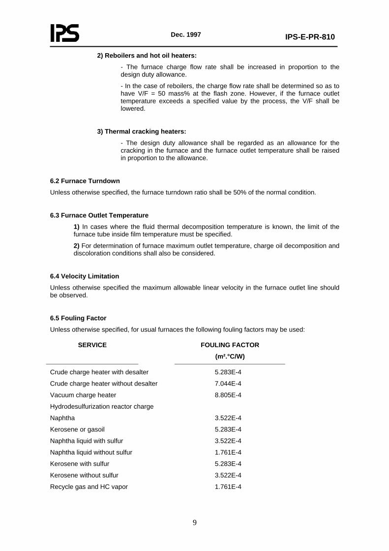
6.5 Fouling Factor
Unless otherwise specified, for usual furnaces the following fouling factors may be used:
SERVICE
FOULING FACTOR
(m².°C/W)
Crude charge heater with desalter 5.283E-4
Crude charge heater without desalter 7.044E-4
Vacuum charge heater 8.805E-4
Hydrodesulfurization reactor charge
Naphtha 3.522E-4
Kerosene or gasoil 5.283E-4
Naphtha liquid with sulfur 3.522E-4
Naphtha liquid without sulfur 1.761E-4
Kerosene with sulfur 5.283E-4
Kerosene without sulfur 3.522E-4
Recycle gas and HC vapor 1.761E-4
Dec. 1997
IPS-E-PR-810
10
6.6 Pressure Drop
In cases where fluid coking is conceivable due to high furnace outlet temperature, the pressure drop shall be calculated for the clean and fouled cases. Unless otherwise specified, the tube coking thickness shall be 3.2 mm (1/8") in the fouled case.
In the case of services where vaporization will occur in the furnace tubes, the flash curves and fluid temperaturephysical property chart (for instance, API, MW, etc.) shall be attached to the data sheet.
Typical values for furnace tube sizes and passes for crude heater are presented in Figs B.1 and B.2 of Appendix B.
6.7 Thermal Design
6.7.1 Calculated and actual efficiencies shall be as required by the process and shown on the data sheets and shall be based on design duty, lower heating value of the primary fuel, relevant excess air for gas and oil firing in natural or forced draft heaters and shall include a maximum radiation loss of 1.5 percent of the calculated (normal) heat release.
Heaters employing air preheat systems shall include a maximum radiation loss of 2.5 percent of the total heat input.
6.7.2 The average radiant heat flux specified on the data sheets is defined as the quotient of total heat absorbed by the radiant tubes divided by the total outside circumferential tube area inside the firebox, including any fitting inside the firebox. The rows of convection tubes exposed to direct radiation shall be considered as being in the radiant section and the maximum radiation heat absorption rate shall apply to these tubes, irrespective of whether extended surface element are used or not.
6.7.3 The maximum radiant heat flux density is defined as the maximum heat rate to any portion of any radiant tube. The rate shall be calculated for the front 60°C of the tube surface. The density is not to be considered as operating average flux density for any given length of tube surface. The maximum tube metal temperature shall be calculated on the basis of the maximum flux density.
6.7.4 Process design conditions are shown on the individual fired heater data sheets. If the fired heater is intended for several cases of operation, the design conditions and operating conditions in each case shall be shown therein.
6.7.5 Vendor shall specify the amount of excess air and stack temperature when operating at the guaranteed efficiency.
6.7.6 Unless otherwise specified, determination of the tube length shall be based on the following criteria.
Where:
Lr is total effective length of radiant tubes;
D is pitch circle of diameter tubes (tube circle diameter);
Lc is total effective length of convection tubes.
6.7.6.1 Maximum L/D values for vertical cylindrical heaters based on design heat absorption rates shall be:
Lr/D 2 for design heat absorption rate up to 3 MW.
Lr/D 2.5 for design heat absorption rate of 3-6 MW.
Lr/D 2.75 for design heat absorption rate over 6 MW.
6.7.6.2 For horizontal tube heaters Lr = Lc
Dec. 1997
IPS-E-PR-810
11
For horizontal end firing Lr = Lc = 15 m max. (Eq. 1)
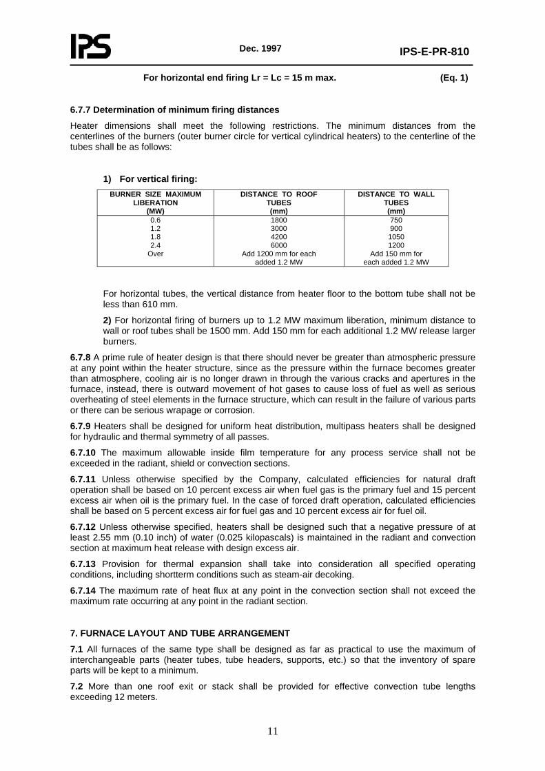
6.7.7 Determination of minimum firing distances
Heater dimensions shall meet the following restrictions. The minimum distances from the centerlines of the burners (outer burner circle for vertical cylindrical heaters) to the centerline of the tubes shall be as follows:
1) For vertical firing: BURNER SIZE MAXIMUM
LIBERATION (MW)
DISTANCE TO ROOF TUBES (mm)
DISTANCE TO WALL TUBES (mm)
0.6 1.2 1.8 2.4
Over
1800 3000 4200 6000
Add 1200 mm for each added 1.2 MW
750 900
1050 1200
Add 150 mm for each added 1.2 MW
For horizontal tubes, the vertical distance from heater floor to the bottom tube shall not be less than 610 mm.
2) For horizontal firing of burners up to 1.2 MW maximum liberation, minimum distance to wall or roof tubes shall be 1500 mm. Add 150 mm for each additional 1.2 MW release larger burners.
6.7.8 A prime rule of heater design is that there should never be greater than atmospheric pressure at any point within the heater structure, since as the pressure within the furnace becomes greater than atmosphere, cooling air is no longer drawn in through the various cracks and apertures in the furnace, instead, there is outward movement of hot gases to cause loss of fuel as well as serious overheating of steel elements in the furnace structure, which can result in the failure of various parts or there can be serious wrapage or corrosion.
6.7.9 Heaters shall be designed for uniform heat distribution, multipass heaters shall be designed for hydraulic and thermal symmetry of all passes.
6.7.10 The maximum allowable inside film temperature for any process service shall not be exceeded in the radiant, shield or convection sections.
6.7.11 Unless otherwise specified by the Company, calculated efficiencies for natural draft operation shall be based on 10 percent excess air when fuel gas is the primary fuel and 15 percent excess air when oil is the primary fuel. In the case of forced draft operation, calculated efficiencies shall be based on 5 percent excess air for fuel gas and 10 percent excess air for fuel oil.
6.7.12 Unless otherwise specified, heaters shall be designed such that a negative pressure of at least 2.55 mm (0.10 inch) of water (0.025 kilopascals) is maintained in the radiant and convection section at maximum heat release with design excess air.
6.7.13 Provision for thermal expansion shall take into consideration all specified operating conditions, including shortterm conditions such as steam-air decoking.
6.7.14 The maximum rate of heat flux at any point in the convection section shall not exceed the maximum rate occurring at any point in the radiant section.
7. FURNACE LAYOUT AND TUBE ARRANGEMENT
7.1 All furnaces of the same type shall be designed as far as practical to use the maximum of interchangeable parts (heater tubes, tube headers, supports, etc.) so that the inventory of spare parts will be kept to a minimum.
7.2 More than one roof exit or stack shall be provided for effective convection tube lengths exceeding 12 meters.
Dec. 1997
IPS-E-PR-810
12
7.3 Minimum clear distance between refractory setting and tube centerline in the radiant section shall be 1.5 nominal tube diameter.
7.4 Radiant heating section tubes shall be single row and minimum center to center distance of adjacent tubes shall be two nominal tube diameters.
7.5 When specified on data sheet, drain connections shall be provided at the lowest point of each heating coil. Normally these drains are located outside the furnace. Pocketed cross overs shall have flanged drain connections and blind flanges. All such connections and flanges shall be of the same material as the parent tubing.
7.6 Steam purge connections shall be provided on all heaters.
7.7 All coils shall be located inside the heater enclosure, except at locations of removable plug fittings and where economics allow return bends in the header boxes. Crossovers from the convection section to the radiant section shall be situated externally and designed for symmetry and for minimum interference with platform area.
7.8 The point within the furnace where there must be a positive means for measuring draft shall be at or quite near the arch or roof of the furnace, this is the highest point of the furnace and the point at which minimum draft exists as the furnace operates. A draft gage shall be used, preferably with the capability for measuring to the nearest 0.255 of a mm WC (1/100 of an inch).
7.9 The convection section tube layout shall include space for future installation of sootblowers or steam lancing doors. The convection section shall incorporate space for future addition of two rows of tubes.
7.10 Shield sections shall have at least three rows of bare tubes.
7.11 Convection sections shall be designed to minimize flue gas bypassing.
7.12 The distance from the center-line of the lowest horizontal radiant tube to the floor of the furnace shall not be less than 300 mm (12 inch).
8. TUBES, TUBE SHEETS, SUPPORTS, HEADERS AND HEADER BOXES
8.1 Only bare tubes shall be used throughout the convection section of liquid firing heaters. If studded or finned tubes are permitted as indicated on data sheets, it shall apply only to the rows of tubes that do not see direct radiation. The metallurgy of the extended surfaces must be suitable for the maximum flue-gas temperature in normal operation and should be suitable for flue-gas temperatures which can exist if there is a tube rupture in the furnace.
8.2 Equivalent bare tubing length for all but the bottom row in the convection section shall be calculated based on the maximum specified average convection absorption rate. The length of extended surface tubing as compared to the equivalent bare tube length can be reduced by as much as 3 to 1.
8.3 All tubes and pipe shall meet the dimensional standards given in API-630 "Tube and Header Dimensions for Fired Heaters for Refinery Services".
8.4 Unless otherwise specified on the data sheets materials for furnace tubes and recycle piping shall be suitable for the maximum metal temperature at the hottest spot and maximum velocity, rather than the average temperature and maximum final velocity.
8.5 Successful bidder will be required to submit backup calculations to substantiate the calculated tubewall temperature and thickness.
8.6 Flanged sections of convection and roof tube support castings shall be protected from source of heat (flame).
8.7 Intermediate tube supports and guides in the radiant section shall be designed to permit replacement of the support without tube removal and with a minimum refractory replacement.
8.8 Header design shall be based on design pressure shown on data sheet and a design temperature 27°C greater than the calculated header metal temperature for headers in header box and the same as adjacent tubes for headers in the firebox. Corrosion allowance on all headers shall be the same as for adjacent tubes.
Dec. 1997
IPS-E-PR-810
13
8.9 Header boxes shall be provided with a drainage connection.
8.10 Snuffing steam shall be made available at furnace header boxes and fireboxes.
8.11 In the breeching and immediately above the convection tubes, the area should be large enough to deliver uniform draft effect to all areas immediately downstream of the convection tubes. Such draft will secure reasonably uniform gas flow/heat transfer to all areas of the convection tubes.
8.12 There must be no outflow of hot gases from the furnace in areas other than through the normal convection outlet or connection to the stack, such an outflow will occur if the furnace pressure should rise unduly.
8.13 For forced draft heaters, the stack breeching, convection section pressure drop relationship must be such that the stack can still hold a minimum draft of 0.76 mm (0.03") WC at the arch or roof of the furnace.
8.14 When the shield and radiant tubes are in the same service, the shield tubes exposed to direct flame radiation shall be of the same material and thickness as the connecting radiant tubes.
8.15 Unless otherwise specified, the maximum length of vertical radiant tubes shall be 18 m (60 ft).
9. BURNERS AND FUEL SYSTEM
9.1 Unless otherwise specified, combination steam atomized oil and gas burners shall be provided and must be capable of firing any combination of fuel gas or liquid fuels specified in the project specifications.
9.2 Unless otherwise specified, a fixed gas fired pilot burner, removable for maintenance while the furnace is in operation shall be provided at each burner assembly, it must be suitable to ensure safe and efficient ignition of all fuels specified.
Each pilot burner shall be permanently lit when its main burner is in use. The pilot flame shall be visible through the burner peep-hole, at least prior to the ignition of the main flame. The pilot burner shall be proven capable of igniting the main fuels efficiently and of remaining lit under all windbox and furnace conditions likely to be experienced.
9.3 Burner fuel and air controls shall be accessible from grade or platforms. Means to view the burner and pilot flame during light off and operating adjustment shall be provided.
9.4 The furnace supplier shall state the heat input of the proposed pilot burners.
9.5 Burners shall be designed to permit automatic operation from 25 to 125% of design heat release. If practical, greater turn-down ratios are desirable.
9.6 Each pilot burner shall be provided with an electric gas ignitor, unless otherwise specified.
9.7 specification of fuels to be burnt will be indicated for each installation.
9.8 Arrangement of the burners shall be in accordance with heater supplier’s standard design so as to give the most uniform tubewall skin temperature. Heat release per burner and arrangement of burners shall be such that the flame will not impinge on the tubes of the heater at a heat release of 50 percent above design with maximum draft. Number of burners and arrangement of burner shall be submitted to the Company for approval.
9.9 Provision shall be included so that atomizing steam and combustion air to each burner can be manually adjusted from normal operating platforms or grade from 25% to 150% of design flow rates.
9.10 All special burner hoses, fitting and special valves shall be supplied by the Vendor.
9.11 All burners are to be equipped with suitable strainers in the pilot lines. Mesh shall be 18/8 SS.
9.12 A minimum of three burners shall be used for liquid fuel fired heaters.
9.13 Burner isolation valves from the main fuels and steam shall not be located under the heater and shall be arranged to be within the arms length of the peep-holes enabling burner flames to be seen.
9.14 Burner isolation valves, including pilot valves shall be ball valves, unless otherwise specified in relevant Company’s valve specification (appropriate class). Clear indication of "open" and
Dec. 1997
IPS-E-PR-810
14
"closed" positions is required.
9.15 In addition to burner steam purging, oil and gas fuel lines between burner valves and burners shall have purging facilities with purging valve adjacent to burner isolation valves.
9.16 Pilot gas isolation valves shall be positioned out of line with the burners.
9.17 A solenoid operated bubble tight shut-off valve shall be installed in each main furnace fuel (including any off gas considered as fuel) line adjacent to the control valve. Operation shall be remote, manual or automatic on closing and manual only opening. Loss of fuel or atomizing steam pressure shall also automatically close these valves. These shutoff valves shall be of high reliability and of a spring close type. Shut-off valves for this service shall not be provided with any bypass valves.
9.18 Main fuel and pilot headers to the furnace shall be equipped with manually operated isolation valves and grouped together with firebox steam purge valves and process blowdown valves between 15 m and 20 m from the furnace in an easily accessible location at grade.
9.19 The regulated pilot gas, shall be from an independent sweet gas supply or from a separate off-take on the fuel gas main (upstream of main fuel gas control valve) with its own spaded block valves. If continuous pilots are specified, additionally a solenoid operated shut-off valve shall be installed in the pilot gas line operated by the emergency shutdown switch only. Low pressure alarm on pilot gas line shall also be fitted.
9.20 The general physical arrangement of pipes, valves and control equipment, etc., at each burner and in the firing floor area as a whole, shall be given specific attention so as to provide a neat, uncluttered and logical layout, capable of being readily identified by the operator and facilitating easy access for operation and maintenance.
9.21 Gas offtakes for individual burners shall be from the top of the header.
9.22 Fuel pipework shall have blanked-off connections to which temporary steam lines may be attached for purging before maintenance. They shall be located close to, and downstream of, the shut-off valves.
9.23 Atomizing steam lines shall be lagged separately from fuel lines.
9.24 Atomizing steam should be supplied via a steam/oil differential pressure controller operable over the specified firing range of the burner.
9.25 All fuel lines shall be independently steam traced as deemed necessary per relevant specification.
9.26 Burner design must offer safe operation, easy maintenance, low emission of particulates SOx/NOx and high efficiency.
9.27 Burner block shall be of prefired refractory shapes and not castable refractory.
9.28 Stable means shall be provided to prevent burner’s tip from carbonization at all loads and conditions.
9.29 For foracd draft/balanced draft heaters, following a main fuel valve trip, the FDF and tripping equipment shall be so arranged that the furnace shall not be unacceptably pressurized.
9.30 In side-wall firing, burners shall be located in areas where maximum heat transfer is demanded. Absolutely zero forward flame is required when the burners are located quite close to the tubes in narrow furnaces in which the tubes may be either vertically or horizontally oriented at the center of the furnace.
9.31 In case of natural-draft vertically fired heaters to be located in high wind atmosphere, it is necessary to erect a wind fence to a height at least three burner diameters above the level of the burners and spaced outwardly approximately the same distance.
9.32 To avoid heat damage, the burner air registers shall be located as remotely as possible from the area where fuel and air come together.
9.33 Sizing of gas headers for groups of burners firing a heater should be based on maximum line velocity at not more than 15 m/s (50 ft/sec), if the pressure as established by the firing controls at entry to the heater is to be presented to all burners so that each burner sees the same fuel gas

Dec. 1997
IPS-E-PR-810
15
pressure for uniform heat release in all areas under control.
9.34 The fuel burning equipment must be suitable for the change in calorific value of the fuel as it may be available.
9.35 For fuel oil burning, the atomizing steam system must deliver dry steam to the burners at constant pressure to hold suitable control of firing in the absence of the sparky fire which is characteristics of most steam atomizing burner oil guns with wet steam.
9.36 The small solid particles in fuel oil make ordinary valves useless for control of oil flow if the valve is to operate in nearly closed position. Valving based on the Vee-port principle must be used to avoid slow stoppage of flow with the valves throttling to any degree.
9.37 The purge valves to be used for burner steam purging shall have complete tightness for assurance of no leakage from the steam system to the oil system.
9.38 Fuel oil take-off connection from the header to the burners shall be made at the top of the header so that solid matter (if any) can be carried past the burner rather than delivered to it.
9.39 In the heater design stage, competent opinion should be sought as to the number of burners to be used and of the design and location of the burners. After the heater is constructed and in operation, it is quite difficult to revise the firing in the interest of more satisfactory conditions of heat transfer. This is particularly true where there are too few large burners. Generally, the greater the number of burners the more likely the heater is to be completely satisfactory. This statement cannot be carried to infinity, but if the choice is between X number of burners and X + 10% number of burners, the larger number should be considered as insurance for greater satisfaction and a better heater.
9.40 The minimum clearance from grade to burner plenum or register shall be 2.0 meters for floor fired heaters.
9.41 Burner block installations shall be designed to expand and contract as a unit, independent of the heater refractory.
9.42 The liquid fuel lines should be large enough with low friction factor.
9.43 When volatile fuels, such as naphtha or gasolines, are burned, a safety interlock shall be provided on each burner.
The interlock design must in sequence shut the fuel off, purge the oil gun and shut the purge medium off before the gun can be removed.
9.44 Unless otherwise specified, the fuel gas pressure at the burners shall be minimum 1.5 bar (ga) [150 kPa (ga)] and the pilot gas burner pressure shall be 0.3 to 0.5 bar (ga) [30 to 50 kPa (ga)] at the burner.
9.45 In cases where offgas is burnt in the furnace (as in the case of the offgas from a vacuum distillation Unit), the offgas composition and operating conditions shall be made clear. In such cases, special type burners will be required and the offgas pressure shall not be less than 0.1 bar (ga) [10 kPa (ga)] at the burners, unless otherwise specified.
9.46 Unless otherwise specified, the fuel oil viscosity shall be less than 42 cSt at the burner and usual steam atomizing burners shall be designed for a fuel oil viscosity of less than 38 cSt.
9.47 Unless otherwise specified, for usual steam atomizing burners, the fuel oil pressure shall be 4 bar (ga) [400 kPa (ga)] at the burner and the steam pressure shall be 5.5 bar (ga) [550 kPa (ga)].
9.48 Net fuel oil consumption/return flow ratio at the fuel oil burner shall be specified in the project specification.
9.49 Valves on return lines from fuel oil headers shall be of globe type so that the flow rate can be controlled by using them.
9.50 Check valves or shut-off valves shall be provided on fuel oil return lines to prevent reverse flow in case of emergency shut-off.
9.51 Plenum chambers around the burners for air ducts or noise muffling devices shall be designed to permit access to burners, pilots and ignitors.
Dec. 1997
IPS-E-PR-810
16
9.52 The plenum chamber shall provide uniform flow distribution to all burners.
9.53 Combination type burners shall be capable of firing fuel gas and fuel oil either together or individually.
9.54 Burner metallurgy shall be designed for low maintenance from erosion, plugging and corrosion consideration.
9.55 The location and general arrangement of burners shall permit adjustment of burner air supply without having to reach into small openings or confined spaces.
9.56 Pilot burners shall be sized to remain alight under maximum furnace draft condition.
9.57 Natural draft burners shall have observation ports in their front plates to give a clear view of the pilot flame and also of the tip of the oil gun.
9.58 Burner air supply is to be protected against variations in wind pressure which cause "blow back" through the burners.
10. STRUCTURAL DESIGN
For this Clause reference is made to IPS-G-ME-200, "Fired Heaters".
11. PLATFORMS, STAIRS AND LADDERS
For this Clause reference is made to IPS-G-ME-200, "Fired Heaters".
12. DUCTS AND STACKS
For this Clause reference is made to IPS-G-ME-200, "Fired Heaters," unless otherwise specified herein.
12.1 Unless otherwise specified, design shall be based on operation at 125% of furnace design capacity with 50% excess air.
12.2 Steel stacks shall have a minimum corrosion allowance of 3 mm (1/8"). The design shall consider the possibility of oscillation at critical wind velocities.
12.3 Stack dampers shall be provided complete with external position indicator and with chain or lever operators accessible from an operating platform or from grade. Positive drive in both opening and closing position shall be provided.
12.4 Stacks shall be equipped with aircraft warning lights per relevant Company’s specification.
12.5 Furnace stacks shall reach at least 7 meters above the highest platform which may require attendance during operation.
12.6 External surface of stack to be metalized and details of metalizing procedure to be submitted for Company’s review and approval.
12.7 Each duct to a common stack shall be equipped with a multiblade louver type damper operable from grade with position indicator and positive drive in both opening and closing direction. Damper failure should be to the open position.
12.8 Facilities shall be provided for draining of condensate from free standing stacks for which a DN 50 (2") minimum size drain shall be provided.
12.9 Particular attention shall be paid to the design of ducting from the furnace fans to the stack to ensure proper performance of fans at all loads.
12.10 Each furnace shall have separate stack, unless otherwise specified.
12.11 Ducting for air and flue gases shall be air tight and sufficiently stiffened.
12.12 In the design of stacks and breechings, the design basis should be conservative to provide ample draft for a potential increase in charge rate or the normal state of fouling which is to be expected.
12.13 The top of stack linings shall be protected to prevent water penetration between the stack
Dec. 1997
IPS-E-PR-810
17
shell plate and the lining.
12.14 When operating with natural draft, control dampers shall be furnished on each heater stack or each inlet air plenum.
12.15 Control dampers shall be designed to move to the specified position in the event of failure of the damper control signal or motive force.
12.16 The size of ducts has to be large enough to enable the burners to work efficiently at their maximum rating, with due allowance being made for the accumulation of dirt and other obstructions.
12.17 The internal surfaces of stack should be as smooth as possible to minimize gas friction. The volume of any pockets (dead spaces) below the flue gas entry should be as small as possible.
12.18 Dampers that are to be manually controlled should always incorporate provisions so that they can be positively secured at the operating position.
12.19 It should be considered that dampers and their actuators can become disconnected and so give a false indication of damper position. Special care is therefore necessary in the design and installation of dampers and actuators.
13. SOOT BLOWERS 13.1 Soot blower requirement shall be specified on data sheets. Adequate number of soot blowers shall be provided to maintain the design heat transfer requirement of the convection section and the air preheater. 13.2 Soot blowers should be of the automatic retractable type for the heater and of the rotary type for the airpreheater. 13.3 Soot blowers shall come complete with the electric motor. Retractable soot blowers shall be operated automatically. Control for automatic sequential operation of soot blowers to be mounted on local panel shall be provided by the Vendor. 13.4 Each soot blower shall also be capable of independent manual operation. The system shall be designed for automatic removal of condensate to avoid water shock to the tubes and keeping steam temperature above saturation upstream of the lance tubes. 13.5 All headers, branches, fittings, valves, drain valves, control valves, pipe hangers and guides as required for soot blowing systems to be supplied. 13.6 The heater supplier shall support his proposal of soot blowers with details of steam flows, jet angle, extent of effective penetration, etc. Suitable stops shall be fitted to the tracks inside the heater, to prevent lances coming off the rails due to overtravel of the drive mechanism. 13.7 The supervisory controls of soot blowers shall ensure that soot blowing does not commence until all the soot blower steam distribution system has reached its working temperature and all condensate has been removed. 13.8 On completion of the operation, complete shut-off of the steam supply shall be assured and drains opened. The drains shall not be connected to other systems from which a blow-back might occur. 13.9 The automatic sequence and system management control shall monitor and indicate all stages of operation. Facilities to interrupt the sequence or obtain selective operation of soot blowers shall be included. 13.10 It shall not be possible to interrupt the supply of steam to a retractable soot blower until it is in the fully-retraced position. 13.11 Means of manually retracting a soot blower shall be provided. 13.12 Heaters using liquid fuel, should be equipped with automatic soot blowers for removing vanadium pentoxide deposits, by operation of a manual switch. 13.13 Steam rate and supply steam pressure shall be specified. 13.14 Unless otherwise specified, individual sootblowers shall be designed to pass a minimum of 4550 kilograms (10,000 pounds) per hour of steam with a minimum steam pressure of 1050 kilopascals (ga) (150 pounds per square inch gage) at the inlet flange. 13.15 Soot blowers shall be equipped with steam inlet valve and drain valve, both to be operated in sequence.
Dec. 1997
IPS-E-PR-810
18
14. FANS AND DRIVERS 14.1 For this Clause reference is made to IPS-G-ME-200, "Fired Heaters", unless otherwise specified herein. 14.2 Fan performance guarantee shall be in accordance with the standard test code of "National Association of Fan Manufacturers". Fan performance shall also be guaranteed to meet all operating conditions specified on the data sheets. A characteristic fan performance curve shall be submitted in Vendor’s proposal for Company’s approval. 14.3 Fans shall be supplied with inlet screen, cleanout door and a silencer. The air intake main connection for the silencer shall be flanged and a minimum of 3.2 mm corrosion allowance shall be considered and pressure drop across each silencer shall not exceed 12.7 mm H2O. 14.4 Draft fan capacity shall be varied by variable louvers furnished by heater supplier. 14.5 Vendor shall furnish for each draft fan inlet a suitable air intake device to reduce sand and dust intake. 14.6 The control of combustion air shall be accomplished by controlling fan inlet damper. The damper operator shall be furnished by the Vendor and shall be equipped with a pneumatic positioner. The damper operator shall be provided with a continuously connected handwheel. 14.7 The heater Vendor shall provide a primary air measuring element for the purpose of measuring total air flow. 14.8 In siting forced draft combustion air fans, care should be exercised to ensure that as far as possible the air intakes will draw clean fresh air. Provision should be made to ensure that:
1) flash steam from steam traps or drains; 2) waste gases or vented combustible gases from plant; 3) fuel gas control systems; 4) entrained combustibles;
should not be entrained into combustion air fan intakes. 15. AIR PREHEATER 15.1 Types of Air Preheat Systems Unless otherwise specified, air preheat systems shall be designed and built in accordance with API RP 533. 16. INSTRUMENTATION, INSTRUMENT AND AUXILIARY CONNECTIONS 16.1 Instrumentation 16.1.1 Vendor shall submit the proposed instrument and control schematic drawings including combustion controls, adequate to fulfill the requirements of his process and mechanical guarantees for Company’s approval (Appendix C shows typical piping and instrument diagrams (P& IDs) for crude heater, crude heater air preheating system and crude heater fuel system). 16.1.2 All instrumentation shall be suitable for continuous working in the conditions of their location. 16.1.3 Provision shall be made for local tripping of critical equipment. 16.1.4 The heater supplier shall be responsible for the satisfactory design and operating capability of the instruments, controls and safety equipment associated with the heater and he shall submit details to the Company for approval. 16.1.5 Control valves shall be specifically selected for the full dynamic turndown of the system, i.e., for start-up and over the full firing range. 16.1.6 Provision shall be made to prevent the fuel supply pressure from falling when additional burners are lit. 16.1.7 Key-operated override switches shall be provided for all shut-down functions. These switches shall also override those start "permissives" which are also shut-down functions. The override switches shall normally be located on the front of the main control panel. If located on the
Dec. 1997
IPS-E-PR-810
19
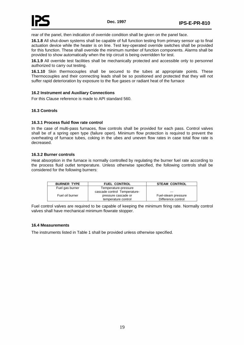
rear of the panel, then indication of override condition shall be given on the panel face. 16.1.8 All shut-down systems shall be capable of full function testing from primary sensor up to final actuation device while the heater is on line. Test key-operated override switches shall be provided for this function. These shall override the minimum number of function components. Alarms shall be provided to show automatically when the trip circuit is being overridden for test. 16.1.9 All override test facilities shall be mechanically protected and accessible only to personnel authorized to carry out testing. 16.1.10 Skin thermocouples shall be secured to the tubes at appropriate points. These Thermocouples and their connecting leads shall be so positioned and protected that they will not suffer rapid deterioration by exposure to the flue gases or radiant heat of the furnace 16.2 Instrument and Auxiliary Connections For this Clause reference is made to API standard 560. 16.3 Controls 16.3.1 Process fluid flow rate control In the case of multi-pass furnaces, flow controls shall be provided for each pass. Control valves shall be of a spring open type (failure open). Minimum flow protection is required to prevent the overheating of furnace tubes, coking in the ubes and uneven flow rates in case total flow rate is decreased. 16.3.2 Burner controls Heat absorption in the furnace is normally controlled by regulating the burner fuel rate according to the process fluid outlet temperature. Unless otherwise specified, the following controls shall be considered for the following burners:
BURNER TYPE FUEL CONTROL STEAM CONTROL Fuel gas burner
Fuel oil burner
Temperature-pressure cascade control Temperature-
pressure cascade or temperature control
---
Fuel-steam pressure Difference control
Fuel control valves are required to be capable of keeping the minimum firing rate. Normally control valves shall have mechanical minimum flowrate stopper.
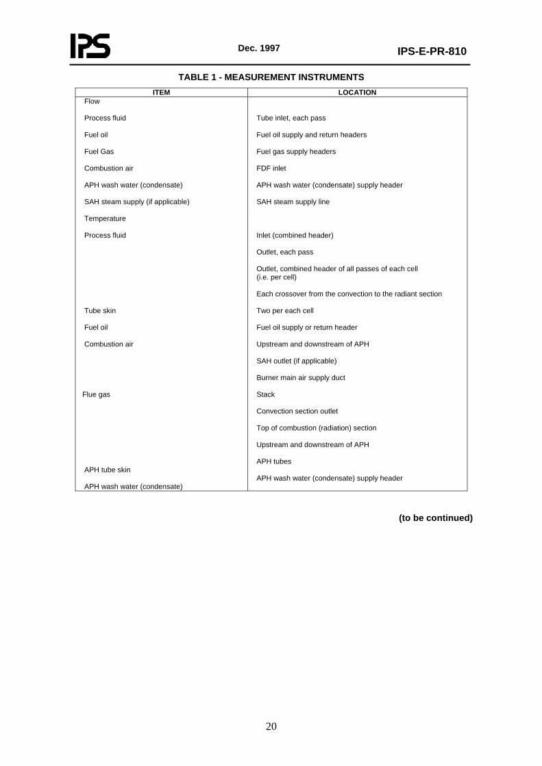
16.4 Measurements
The instruments listed in Table 1 shall be provided unless otherwise specified.
Dec. 1997
IPS-E-PR-810
20
TABLE 1 - MEASUREMENT INSTRUMENTS ITEM LOCATION
Flow Process fluid Fuel oil Fuel Gas Combustion air APH wash water (condensate) SAH steam supply (if applicable) Temperature Process fluid Tube skin Fuel oil Combustion air Flue gas APH tube skin APH wash water (condensate)
Tube inlet, each pass Fuel oil supply and return headers Fuel gas supply headers FDF inlet APH wash water (condensate) supply header SAH steam supply line Inlet (combined header) Outlet, each pass Outlet, combined header of all passes of each cell (i.e. per cell) Each crossover from the convection to the radiant section Two per each cell Fuel oil supply or return header Upstream and downstream of APH SAH outlet (if applicable) Burner main air supply duct Stack Convection section outlet Top of combustion (radiation) section Upstream and downstream of APH APH tubes APH wash water (condensate) supply header
(to be continued)
Dec. 1997
IPS-E-PR-810
21
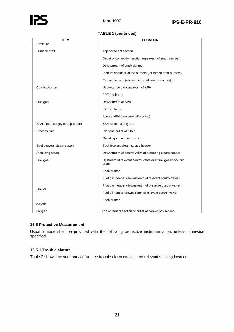
TABLE 1 (continued) ITEM LOCATION
Pressure Furnace draft Combustion air Fuel gas SAH steam supply (if applicable) Process fluid Soot blowers steam supply Atomizing steam Fuel gas Fuel oil
Top of radiant section Outlet of convection section (upstream of stack damper) Downstream of stack damper Plenum chamber of the burners (for forced draft burners) Radiant section (above the top of floor refractory) Upstream and downstream of APH FDF discharge Downstream of APH IDF discharge Across APH (pressure differential) SAH steam supply line Inlet and outlet of tubes Outlet piping or flash zone Soot blowers steam supply header Downstream of control valve of atomizing steam header Upstream of relevant control valve or at fuel gas knock out drum Each burner Fuel gas header (downstream of relevant control valve) Pilot gas header (downstream of pressure control valve) Fuel oil header (downstream of relevant control valve) Each burner
Analysis Oxygen
Top of radiant section or outlet of convection section
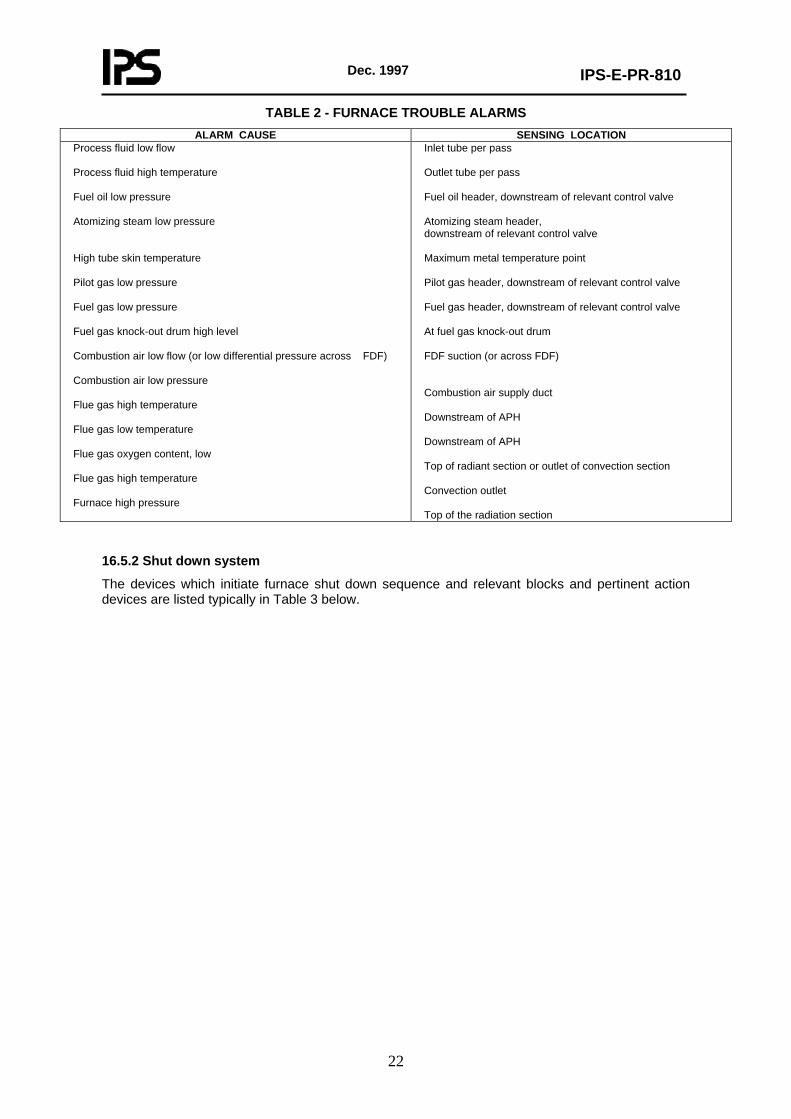
16.5 Protective Measurement
Usual furnace shall be provided with the following protective instrumentation, unless otherwise specified:
16.5.1 Trouble alarms
Table 2 shows the summary of furnace trouble alarm causes and relevant sensing location.
Dec. 1997
IPS-E-PR-810
22
TABLE 2 - FURNACE TROUBLE ALARMS ALARM CAUSE SENSING LOCATION
Process fluid low flow
Process fluid high temperature Fuel oil low pressure Atomizing steam low pressure High tube skin temperature Pilot gas low pressure Fuel gas low pressure Fuel gas knock-out drum high level Combustion air low flow (or low differential pressure across FDF) Combustion air low pressure Flue gas high temperature Flue gas low temperature Flue gas oxygen content, low Flue gas high temperature Furnace high pressure
Inlet tube per pass Outlet tube per pass Fuel oil header, downstream of relevant control valve Atomizing steam header, downstream of relevant control valve Maximum metal temperature point Pilot gas header, downstream of relevant control valve Fuel gas header, downstream of relevant control valve At fuel gas knock-out drum FDF suction (or across FDF) Combustion air supply duct Downstream of APH Downstream of APH Top of radiant section or outlet of convection section Convection outlet Top of the radiation section
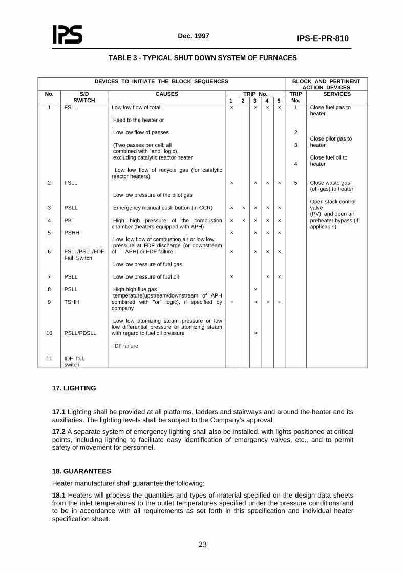
16.5.2 Shut down system
The devices which initiate furnace shut down sequence and relevant blocks and pertinent action devices are listed typically in Table 3 below.
Dec. 1997
IPS-E-PR-810
23
TABLE 3 - TYPICAL SHUT DOWN SYSTEM OF FURNACES
DEVICES TO INITIATE THE BLOCK SEQUENCES BLOCK AND PERTINENT
ACTION DEVICES TRIP No. No. S/D
SWITCH CAUSES
1 2 3 4 5 TRIP No.
SERVICES
1
2
3
4
5
6
7
8
9
10
11
FSLL FSLL PSLL PB PSHH FSLL/PSLL/FDF Fail Switch PSLL PSLL TSHH PSLL/PDSLL IDF fail. switch
Low low flow of total Feed to the heater or Low low flow of passes (Two passes per cell, all combined with "and" logic), excluding catalytic reactor heater Low low flow of recycle gas (for catalytic reactor heaters) Low low pressure of the pilot gas Emergency manual push button (in CCR) High high pressure of the combustion chamber (heaters equipped with APH) Low low flow of combustion air or low low pressure at FDF discharge (or downstream of APH) or FDF failure Low low pressure of fuel gas Low low pressure of fuel oil High high flue gas temperature(upstream/downstream of APH combined with "or" logic), if specified by company Low low atomizing steam pressure or low low differential pressure of atomizing steam with regard to fuel oil pressure IDF failure
×
×
×
×
×
×
×
×
×
×
×
×
×
×
×
×
×
×
×
×
×
×
×
×
×
×
×
×
×
×
×
×
×
×
×
1
2
3
4
5
Close fuel gas to heater Close pilot gas to heater Close fuel oil to heater Close waste gas (off-gas) to heater Open stack control valve (PV) and open air preheater bypass (if applicable)
17. LIGHTING
17.1 Lighting shall be provided at all platforms, ladders and stairways and around the heater and its auxiliaries. The lighting levels shall be subject to the Company’s approval.
17.2 A separate system of emergency lighting shall also be installed, with lights positioned at critical points, including lighting to facilitate easy identification of emergency valves, etc., and to permit safety of movement for personnel.
18. GUARANTEES
Heater manufacturer shall guarantee the following:
18.1 Heaters will process the quantities and types of material specified on the design data sheets from the inlet temperatures to the outlet temperatures specified under the pressure conditions and to be in accordance with all requirements as set forth in this specification and individual heater specification sheet.
Dec. 1997
IPS-E-PR-810
24
18.2 Heaters will provide the specified performance without exceeding supplier’s specified maximum tubewall or refractory temperatures when temperature is measured with tube skin thermocouples. Location of peepholes to be used for guarantee test shall be marked on Vendor’s drawing. The use of pyrometers or thermocouples for this check shall be at the option of the Company.
18.3 Heater tubes will be completely free of all flame impingement.
18.4 Instruments are free from fault in design, workmanship and material to fulfill satisfactorily the operating conditions specified.
18.5 All parts which prove defective under operating use within one year from the start of operation because of design, workmanship or materials used will be repaired or replaced with all charges of freight, site labor and supervision to be paid for by the supplier.
18.6 Supplier shall guarantee all utility consumptions, including fuel gas consumption without any positive tolerances.
Supplier shall indicate the guaranteed figures in his technical proposal.
18.7 At the option of Company, an efficiency test shall be made in accordance with generally accepted procedures during a period of normal operation. In the event that it is established by such test that the efficiency is less than that guaranteed, heater supplier shall make alterations and/or additions to the equipment as required to attain the guaranteed efficiency. Heater supplier shall bear the entire cost of making such changes.
19. REQUIRED INFORMATION/DOCUMENTS
19.1 All drawings and literature must be in English language and must show all dimensions, capacities, etc., in metric SI units.
19.2 The purchase order number shall be prominently shown on all documents. Drawings shall be properly protected and packed and mylars shall be dispatched in a strong cardboard cylinder. Drawings shall be rolled (not folded).
19.3 Complete data sheets shall be filled out for each heater, including isoflash curve; charge properties; curves of enthalpy vs. vaporization; flowing density (liquids) vs. temperature; specific volume (vapor) vs.temperature.
19.4 Information Required with the Quotation
19.4.1 Guaranteed operating absorbed duty and fuel consumption.
19.4.2 All average heat absorption rates in radiant and convection sections.
19.4.3 Guaranteed maximum tube skin temperatures for all tube materials and maximum support metal temperatures.
19.4.4 Tube spacing and general tube arrangement drawings.
19.4.5 Tube material, diameter and tube thickness broken down to minimum thickness and corrosion allowance.
19.4.6 Description and drawing of heater and return bend arrangement.
19.4.7 Number, detail and description drawing of burners.
19.4.8 Preliminary location of all inlet and outlet connections, instrument connections, steam out connections, drain connections and all other miscellaneous connections.
19.4.9 Construction drawings should be provided showing the principal section of the heater, the number, size, arrangement, material specification and fabrication details of coil components, arrangement and specifications of burners, tube supports, ductwork, stack, damping devices, observation ports and platforms.
19.4.10 A drawing showing overall dimensions for layout purposes.
Dec. 1997
IPS-E-PR-810
25
19.4.11 A drawing showing the general layout of the firebox, including tubing, burners, flue ducts, ladders, stairways and platforms.
19.4.12 Approximate operating mass (weight) of furnaces (operating and under hydrotest).
19.4.13 Statement indicating conformity to the specification or list of exceptions.
19.4.14 Description of the degree of shop fabrication for base bid, this must show number of shop welds and total field welds to assemble furnace tubes and headers.
19.4.15 Type and thickness of refractory and description of method of application.
19.4.16 A price recommended spare list for one year of operation.
19.4.17 Standard data sheet for each item completely filled out.
19.4.18 Heater process flow sheet (including APH system) at design case/normal case/turn-down case (Appendix D shows typical heater process flow sheet).
19.5 Information Required Against Purchase Order
19.5.1 Final dimensional drawings and detailed design of all items specified in paragraphs 25.4.1 through 25.4.17 above (for Company’s approval)..
19.5.2 Details of fabrication, welding procedure and material specification for all coil components (for Company’s approval).
19.5.3 Calculated thickness for tube supports (for Company’s approval).
19.5.4 List of recommended commissioning spares with prices.
19.5.5 Details of any special tools required.
19.5.6 Illustrated comprehensive spare parts manual with part numbers suitable for warehouse stocking.
19.5.7 Illustrated installation and operating instructions.
19.5.8 Maintenance manuals.
19.5.9 Calculated thickness and stress analysis for hydrocracking and hydrodesulfurization heater tubes (for Company’s approval).
19.5.10 For hydrogen reformer heater all information called for by the relevant specifications and calculated tube thickness (for Company’s approval).
19.5.11 Calculations for heat flux, maximum skin temperature and pressure gradient inside the tubes (for Company’s approval).
19.5.12 Individual specification data sheets for fans and other ancillary equipment, indicating turbine steam rate/- power, fan test block conditions at this power (kW) shall be indicated.
19.5.13 Statement of the maximum anticipated noise levels at full heater capacity.
19.5.14 Soot blowers type, location, manufacturer and arrangement.
19.5.15 Statement of furnace positive and negative pressures.
19.5.16 Method of fuel consumption and thermal efficiency tests, with correction formula, curves, etc., used in the calculations.
19.5.17 Approximate dimensions, layout and location of local and remote control panels.
19.5.18 List of the major control loops, general statement of local and remote panel instrumentations.
19.5.19 Design and construction of flue gas dampers.
19.5.20 Specifications, data sheets, sizing data and proposed suppliers of control equipment.
19.5.21 Schematic and hook-up drawings of emergency shutdown systems and automatic trip systems, accompanied by a detailed description of operation.
Dec. 1997
IPS-E-PR-810
26
19.5.22 Design details and mode of operation for isolating plates in common ducting or stack.
19.5.23 Design of stack duct entries.
19.5.24 Winterization proposals for plant protection.
19.5.25 Instruction for installation, operation and maintenance of soot blowers.
19.5.26 Instruction for installation, operation and maintenance of burners.
19.5.27 Instruction for installation, operation and maintenance of fans.
19.5.28 Instruction for installation, operation and maintenance of air preheater.
Dec. 1997
IPS-E-PR-810
27
APPENDICES
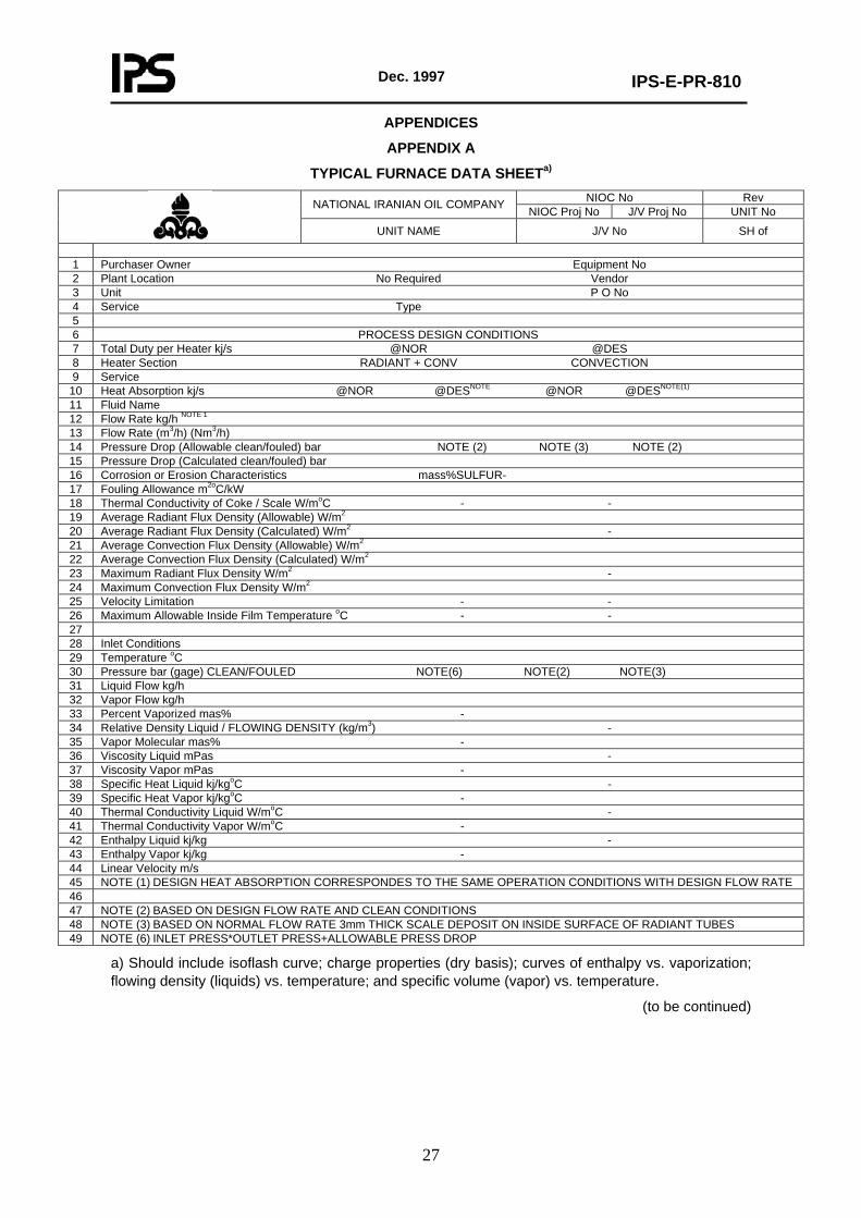
APPENDIX A
TYPICAL FURNACE DATA SHEETa)
NIOC No Rev NATIONAL IRANIAN OIL COMPANY NIOC Proj No J/V Proj No UNIT No
UNIT NAME J/V No SH of
1 Purchaser Owner Equipment No 2 Plant Location No Required Vendor 3 Unit P O No 4 Service Type 5 6 PROCESS DESIGN CONDITIONS 7 Total Duty per Heater kj/s @NOR @DES 8 Heater Section RADIANT + CONV CONVECTION 9 Service
10 Heat Absorption kj/s @NOR @DESNOTE @NOR @DESNOTE(1) 11 Fluid Name 12 Flow Rate kg/h NOTE 1 13 Flow Rate (m3/h) (Nm3/h) 14 Pressure Drop (Allowable clean/fouled) bar NOTE (2) NOTE (3) NOTE (2) 15 Pressure Drop (Calculated clean/fouled) bar 16 Corrosion or Erosion Characteristics mass%SULFUR- 17 Fouling Allowance m2oC/kW 18 Thermal Conductivity of Coke / Scale W/moC - - 19 Average Radiant Flux Density (Allowable) W/m2 20 Average Radiant Flux Density (Calculated) W/m2 - 21 Average Convection Flux Density (Allowable) W/m2 22 Average Convection Flux Density (Calculated) W/m2 23 Maximum Radiant Flux Density W/m2 - 24 Maximum Convection Flux Density W/m2 25 Velocity Limitation - - 26 Maximum Allowable Inside Film Temperature oC - - 27 28 Inlet Conditions 29 Temperature oC 30 Pressure bar (gage) CLEAN/FOULED NOTE(6) NOTE(2) NOTE(3) 31 Liquid Flow kg/h 32 Vapor Flow kg/h 33 Percent Vaporized mas% - 34 Relative Density Liquid / FLOWING DENSITY (kg/m3) - 35 Vapor Molecular mas% - 36 Viscosity Liquid mPas - 37 Viscosity Vapor mPas - 38 Specific Heat Liquid kj/kgoC - 39 Specific Heat Vapor kj/kgoC - 40 Thermal Conductivity Liquid W/moC - 41 Thermal Conductivity Vapor W/moC - 42 Enthalpy Liquid kj/kg - 43 Enthalpy Vapor kj/kg - 44 Linear Velocity m/s 45 NOTE (1) DESIGN HEAT ABSORPTION CORRESPONDES TO THE SAME OPERATION CONDITIONS WITH DESIGN FLOW RATE 46 47 NOTE (2) BASED ON DESIGN FLOW RATE AND CLEAN CONDITIONS 48 NOTE (3) BASED ON NORMAL FLOW RATE 3mm THICK SCALE DEPOSIT ON INSIDE SURFACE OF RADIANT TUBES 49 NOTE (6) INLET PRESS*OUTLET PRESS+ALLOWABLE PRESS DROP
a) Should include isoflash curve; charge properties (dry basis); curves of enthalpy vs. vaporization; flowing density (liquids) vs. temperature; and specific volume (vapor) vs. temperature.
(to be continued)
Dec. 1997
IPS-E-PR-810
28
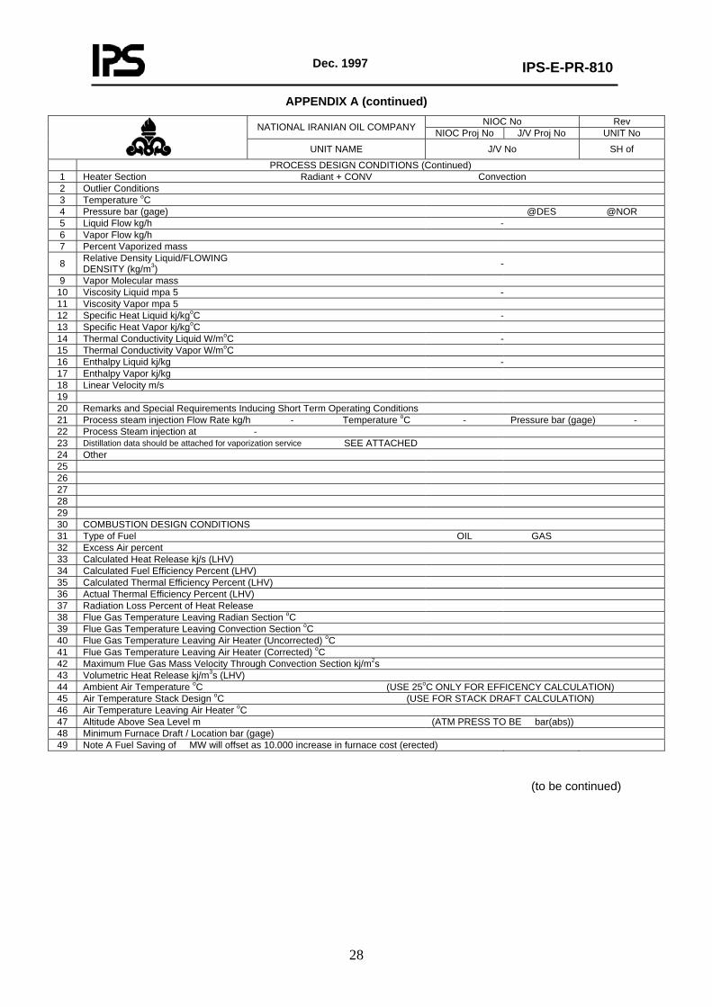
APPENDIX A (continued) NIOC No Rev NATIONAL IRANIAN OIL COMPANY NIOC Proj No J/V Proj No UNIT No
UNIT NAME J/V No SH of
PROCESS DESIGN CONDITIONS (Continued) 1 Heater Section Radiant + CONV Convection 2 Outlier Conditions 3 Temperature oC 4 Pressure bar (gage) @DES @NOR 5 Liquid Flow kg/h - 6 Vapor Flow kg/h 7 Percent Vaporized mass
8 Relative Density Liquid/FLOWING DENSITY (kg/m3) -
9 Vapor Molecular mass 10 Viscosity Liquid mpa 5 - 11 Viscosity Vapor mpa 5 12 Specific Heat Liquid kj/kgoC - 13 Specific Heat Vapor kj/kgoC 14 Thermal Conductivity Liquid W/moC - 15 Thermal Conductivity Vapor W/moC 16 Enthalpy Liquid kj/kg - 17 Enthalpy Vapor kj/kg 18 Linear Velocity m/s 19 20 Remarks and Special Requirements Inducing Short Term Operating Conditions 21 Process steam injection Flow Rate kg/h - Temperature oC - Pressure bar (gage) - 22 Process Steam injection at - 23 Distillation data should be attached for vaporization service SEE ATTACHED 24 Other 25 26 27 28 29 30 COMBUSTION DESIGN CONDITIONS 31 Type of Fuel OIL GAS 32 Excess Air percent 33 Calculated Heat Release kj/s (LHV) 34 Calculated Fuel Efficiency Percent (LHV) 35 Calculated Thermal Efficiency Percent (LHV) 36 Actual Thermal Efficiency Percent (LHV) 37 Radiation Loss Percent of Heat Release 38 Flue Gas Temperature Leaving Radian Section oC 39 Flue Gas Temperature Leaving Convection Section oC 40 Flue Gas Temperature Leaving Air Heater (Uncorrected) oC 41 Flue Gas Temperature Leaving Air Heater (Corrected) oC 42 Maximum Flue Gas Mass Velocity Through Convection Section kj/m2s 43 Volumetric Heat Release kj/m3s (LHV) 44 Ambient Air Temperature oC (USE 25oC ONLY FOR EFFICENCY CALCULATION) 45 Air Temperature Stack Design oC (USE FOR STACK DRAFT CALCULATION) 46 Air Temperature Leaving Air Heater oC 47 Altitude Above Sea Level m (ATM PRESS TO BE bar(abs)) 48 Minimum Furnace Draft / Location bar (gage) 49 Note A Fuel Saving of MW will offset as 10.000 increase in furnace cost (erected)
(to be continued)
Dec. 1997
IPS-E-PR-810
29
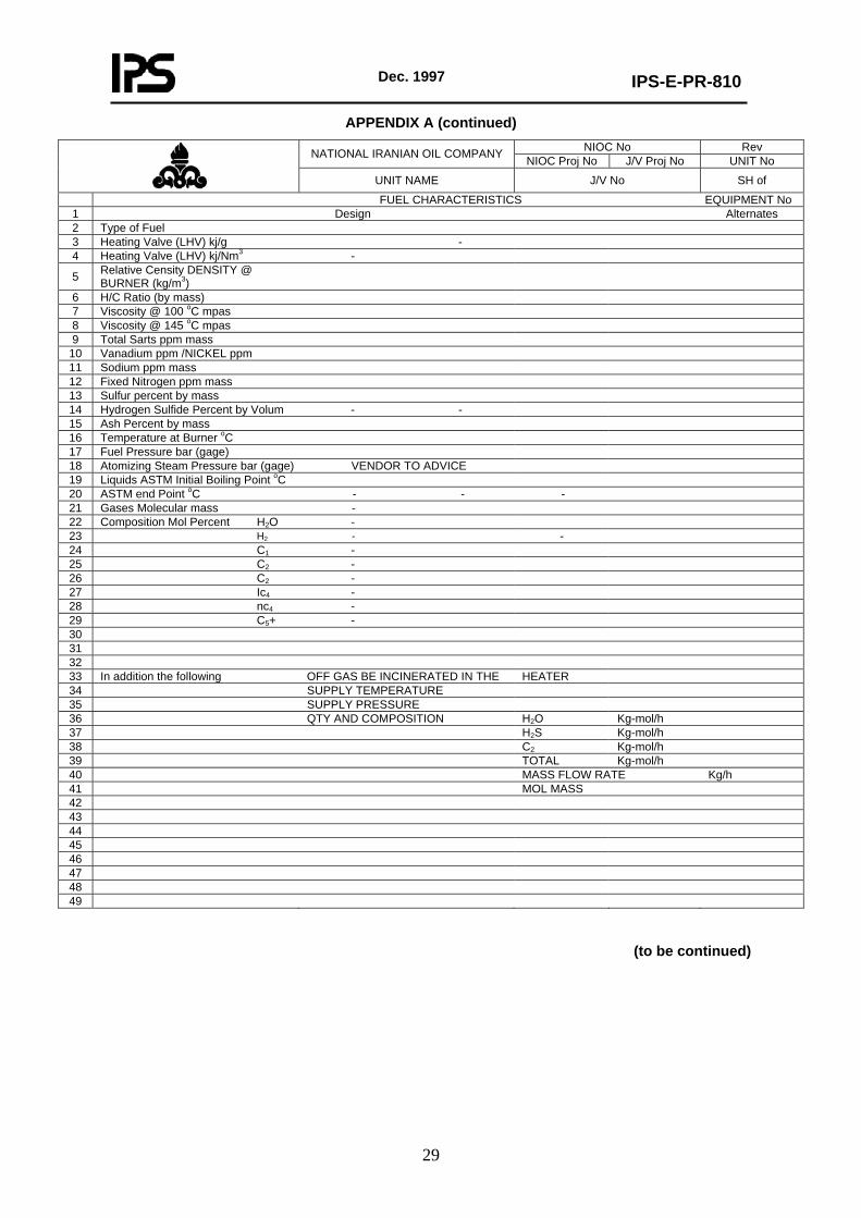
APPENDIX A (continued) NIOC No Rev NATIONAL IRANIAN OIL COMPANY NIOC Proj No J/V Proj No UNIT No
UNIT NAME J/V No SH of
FUEL CHARACTERISTICS EQUIPMENT No 1 Design Alternates 2 Type of Fuel 3 Heating Valve (LHV) kj/g - 4 Heating Valve (LHV) kj/Nm3 -
5 Relative Censity DENSITY @ BURNER (kg/m3)
6 H/C Ratio (by mass) 7 Viscosity @ 100 oC mpas 8 Viscosity @ 145 oC mpas 9 Total Sarts ppm mass
10 Vanadium ppm /NICKEL ppm 11 Sodium ppm mass 12 Fixed Nitrogen ppm mass 13 Sulfur percent by mass 14 Hydrogen Sulfide Percent by Volum - - 15 Ash Percent by mass 16 Temperature at Burner oC 17 Fuel Pressure bar (gage) 18 Atomizing Steam Pressure bar (gage) VENDOR TO ADVICE 19 Liquids ASTM Initial Boiling Point oC 20 ASTM end Point oC - - - 21 Gases Molecular mass - 22 Composition Mol Percent H2O - 23 H2 - - 24 C1 - 25 C2 - 26 C2 - 27 Ic4 - 28 nc4 - 29 C5+ - 30 31 32 33 In addition the following OFF GAS BE INCINERATED IN THE HEATER 34 SUPPLY TEMPERATURE 35 SUPPLY PRESSURE 36 QTY AND COMPOSITION H2O Kg-mol/h 37 H2S Kg-mol/h 38 C2 Kg-mol/h 39 TOTAL Kg-mol/h 40 MASS FLOW RATE Kg/h 41 MOL MASS 42 43 44 45 46 47 48 49
(to be continued)
Dec. 1997
IPS-E-PR-810
30
APPENDIX A (continued)
NIOC No Rev NATIONAL IRANIAN OIL COMPANY NIOC Proj No J/V Proj No UNIT No
UNIT NAME J/V No SH of
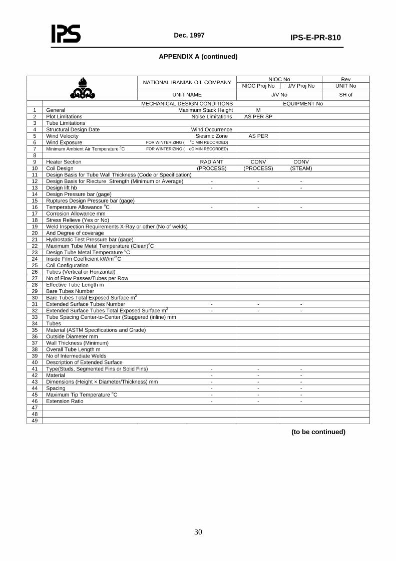
MECHANICAL DESIGN CONDITIONS EQUIPMENT No 1 General Maximum Stack Height M 2 Plot Limitations Noise Limitations AS PER SP 3 Tube Limitations 4 Structural Design Date Wind Occurrence 5 Wind Velocity Siesmic Zone AS PER 6 Wind Exposure FOR WINTERIZING ( oC MIN RECORDED) 7 Minimum Ambient Air Temperature oC FOR WINTERIZING ( oC MIN RECORDED) 8 9 Heater Section RADIANT CONV CONV
10 Coil Design (PROCESS) (PROCESS) (STEAM) 11 Design Basis for Tube Wall Thickness (Code or Specification) 12 Design Basis for Riecture Strength (Minimum or Average) - - - 13 Design lift hb - - - 14 Design Pressure bar (gage) 15 Ruptures Design Pressure bar (gage) 16 Temperature Allowance oC - - - 17 Corrosion Allowance mm 18 Stress Relieve (Yes or No) 19 Weld Inspection Requirements X-Ray or other (No of welds) 20 And Degree of coverage 21 Hydrostatic Test Pressure bar (gage) 22 Maximum Tube Metal Temperature (Clean)oC 23 Design Tube Metal Temperature oC 24 Inside Film Coefficient kW/m2oC 25 Coil Configuration 26 Tubes (Vertical or Horizantal) 27 No of Flow Passes/Tubes per Row 28 Effective Tube Length m 29 Bare Tubes Number 30 Bare Tubes Total Exposed Surface m2 31 Extended Surface Tubes Number - - - 32 Extended Surface Tubes Total Exposed Surface m2 - - - 33 Tube Spacing Center-to-Center (Staggered (inline) mm 34 Tubes 35 Material (ASTM Specifications and Grade) 36 Outside Diameter mm 37 Wall Thickness (Minimum) 38 Overall Tube Length m 39 No of Intermediate Welds 40 Description of Extended Surface 41 Type(Studs, Segmented Fins or Solid Fins) - - - 42 Material - - - 43 Dimensions (Height × Diameter/Thickness) mm - - - 44 Spacing - - - 45 Maximum Tip Temperature oC - - - 46 Extension Ratio - - - 47 48 49
(to be continued)
Dec. 1997
IPS-E-PR-810
31
APPENDIX A (continued)
NIOC No Rev NATIONAL IRANIAN OIL COMPANY NIOC Proj No J/V Proj No UNIT No
UNIT NAME J/V No SH of
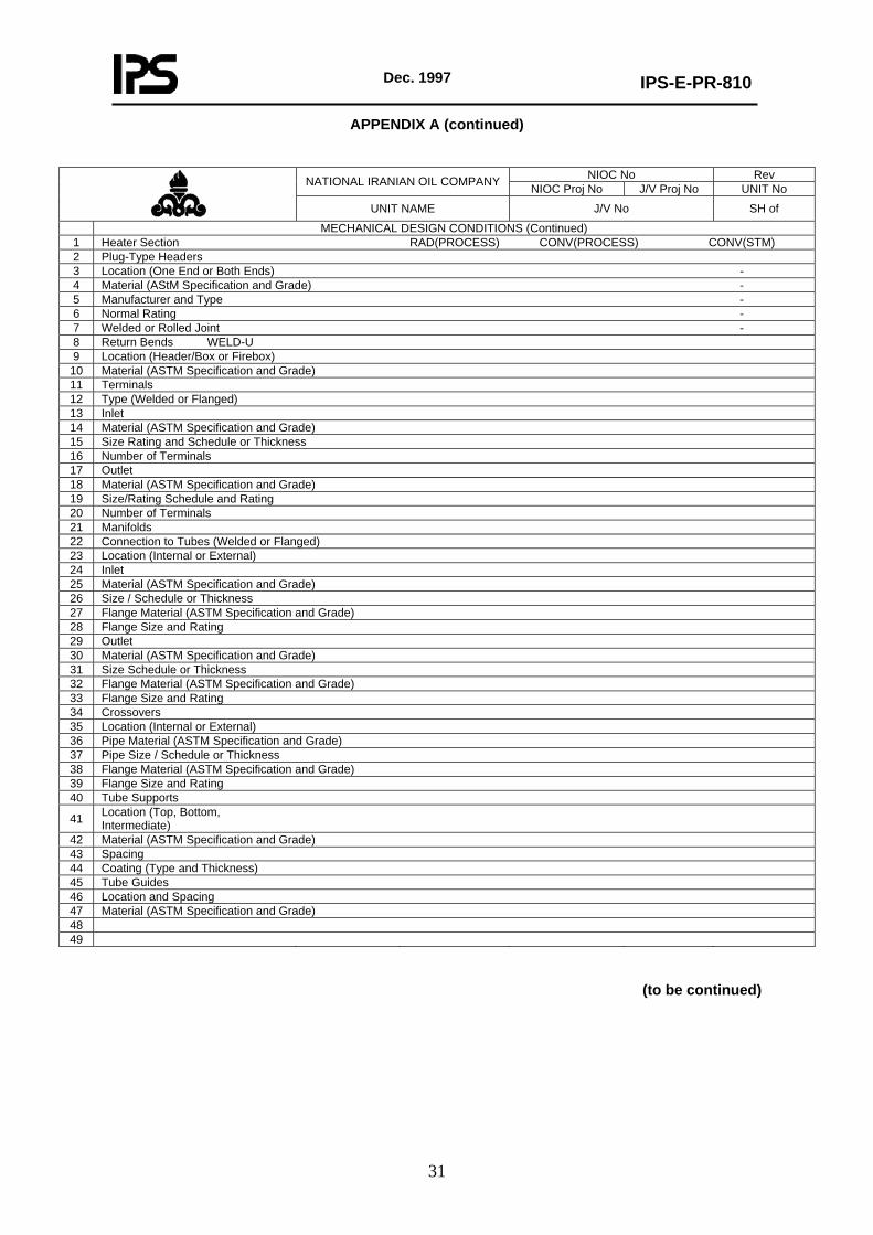
MECHANICAL DESIGN CONDITIONS (Continued) 1 Heater Section RAD(PROCESS) CONV(PROCESS) CONV(STM) 2 Plug-Type Headers 3 Location (One End or Both Ends) - 4 Material (AStM Specification and Grade) - 5 Manufacturer and Type - 6 Normal Rating - 7 Welded or Rolled Joint - 8 Return Bends WELD-U 9 Location (Header/Box or Firebox)
10 Material (ASTM Specification and Grade) 11 Terminals 12 Type (Welded or Flanged) 13 Inlet 14 Material (ASTM Specification and Grade) 15 Size Rating and Schedule or Thickness 16 Number of Terminals 17 Outlet 18 Material (ASTM Specification and Grade) 19 Size/Rating Schedule and Rating 20 Number of Terminals 21 Manifolds 22 Connection to Tubes (Welded or Flanged) 23 Location (Internal or External) 24 Inlet 25 Material (ASTM Specification and Grade) 26 Size / Schedule or Thickness 27 Flange Material (ASTM Specification and Grade) 28 Flange Size and Rating 29 Outlet 30 Material (ASTM Specification and Grade) 31 Size Schedule or Thickness 32 Flange Material (ASTM Specification and Grade) 33 Flange Size and Rating 34 Crossovers 35 Location (Internal or External) 36 Pipe Material (ASTM Specification and Grade) 37 Pipe Size / Schedule or Thickness 38 Flange Material (ASTM Specification and Grade) 39 Flange Size and Rating 40 Tube Supports
41 Location (Top, Bottom, Intermediate)
42 Material (ASTM Specification and Grade) 43 Spacing 44 Coating (Type and Thickness) 45 Tube Guides 46 Location and Spacing 47 Material (ASTM Specification and Grade) 48 49
(to be continued)
Dec. 1997
IPS-E-PR-810
32
APPENDIX A (continued)
NIOC No Rev NATIONAL IRANIAN OIL COMPANY NIOC Proj No J/V Proj No UNIT No
UNIT NAME J/V No SH of
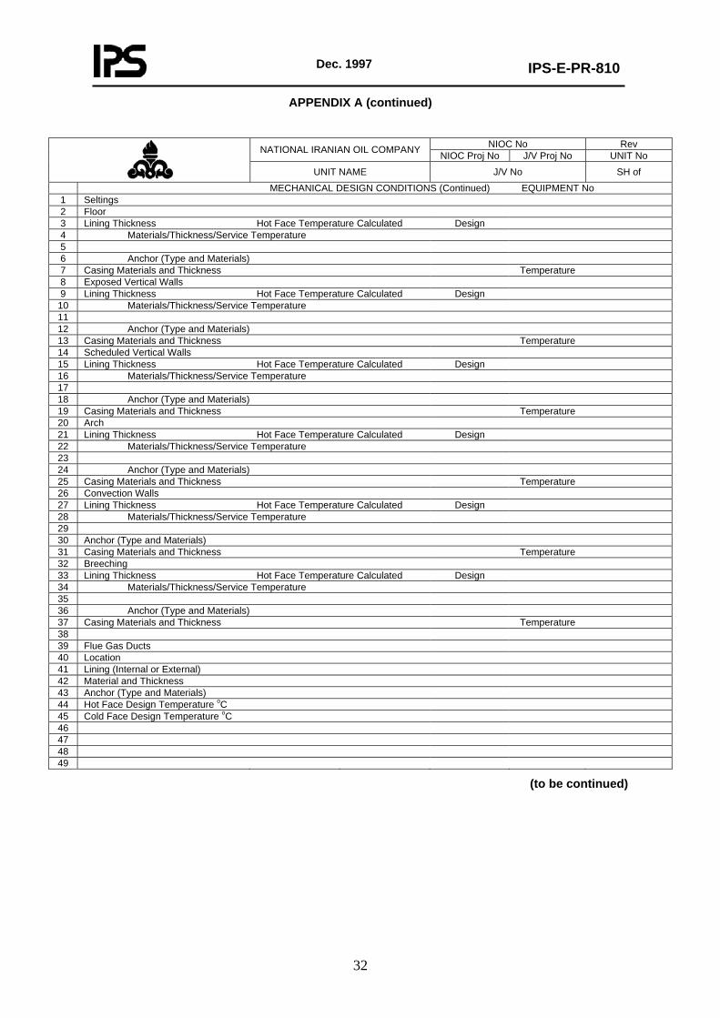
MECHANICAL DESIGN CONDITIONS (Continued) EQUIPMENT No 1 Seltings 2 Floor 3 Lining Thickness Hot Face Temperature Calculated Design 4 Materials/Thickness/Service Temperature 5 6 Anchor (Type and Materials) 7 Casing Materials and Thickness Temperature 8 Exposed Vertical Walls 9 Lining Thickness Hot Face Temperature Calculated Design
10 Materials/Thickness/Service Temperature 11 12 Anchor (Type and Materials) 13 Casing Materials and Thickness Temperature 14 Scheduled Vertical Walls 15 Lining Thickness Hot Face Temperature Calculated Design 16 Materials/Thickness/Service Temperature 17 18 Anchor (Type and Materials) 19 Casing Materials and Thickness Temperature 20 Arch 21 Lining Thickness Hot Face Temperature Calculated Design 22 Materials/Thickness/Service Temperature 23 24 Anchor (Type and Materials) 25 Casing Materials and Thickness Temperature 26 Convection Walls 27 Lining Thickness Hot Face Temperature Calculated Design 28 Materials/Thickness/Service Temperature 29 30 Anchor (Type and Materials) 31 Casing Materials and Thickness Temperature 32 Breeching 33 Lining Thickness Hot Face Temperature Calculated Design 34 Materials/Thickness/Service Temperature 35 36 Anchor (Type and Materials) 37 Casing Materials and Thickness Temperature 38 39 Flue Gas Ducts 40 Location 41 Lining (Internal or External) 42 Material and Thickness 43 Anchor (Type and Materials) 44 Hot Face Design Temperature oC 45 Cold Face Design Temperature oC 46 47 48 49
(to be continued)
Dec. 1997
IPS-E-PR-810
33
APPENDIX A (continued)
NIOC No Rev NATIONAL IRANIAN OIL COMPANY NIOC Proj No J/V Proj No UNIT No
UNIT NAME J/V No SH of
MECHANICAL DESIGN CONDITIONS (Continued) Equipment No 1 Combustion Air Ducts 2 Location 3 Lining (Internal or External) 4 Material and Thickness 5 Anchor Type and Material 6 Hot Face Design Temperature oC 7 Header Boxes 8 Location Hinged Doors Bolted Panels 9 Lining (Material and Thickness)
10 Anchor (Type and Material) 11 Door/Panel (Material and Thickness) 12 Plenum Chamber 13 Lining (Internal or External) Material and Thickness 14 Anchor (Type and Material) 15 Casing Materials and Thickness 16 Hot Face Design Temperature Cold Face Design Temperature 17 Stack 18 Location Number Inside Metal Diameter Height Above Ground 19 Stack Design Material Temperature Stack Length 20 Plate, Minimum Thickness (Including Corrosion Allowance) Material C.A. 21 Lining (Internal or External) 22 Material and Thickness 23 Anchor (Type and Material) 24 Bridge Well 25 Height Material and Thickness Location 26 Damper 27 Location 28 Material of Blade 29 Material of Shaft 30 Bearing Type 31 Multiple or Single Blade 32 Description of Provision for Operation 33 Location and Type of Operation 34 Miscellaneous 35 Platforms Access by Access from 36 Location No Width Length/ Arc Grade/Platform/Location etc 37 38 39 40 41 42 Type of Flooring. etc 43 44 45 46 47 48 49
(to be continued)
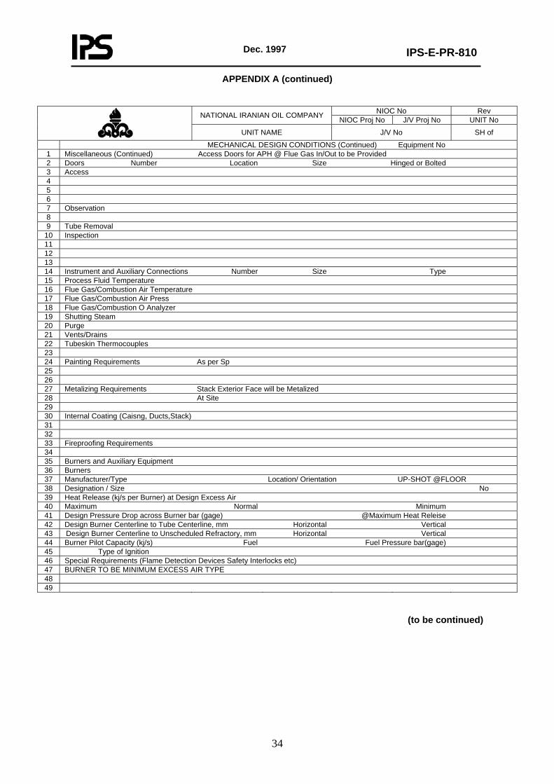
Dec. 1997
IPS-E-PR-810
34
APPENDIX A (continued)
NIOC No Rev NATIONAL IRANIAN OIL COMPANY NIOC Proj No J/V Proj No UNIT No
UNIT NAME J/V No SH of
MECHANICAL DESIGN CONDITIONS (Continued) Equipment No 1 Miscellaneous (Continued) Access Doors for APH @ Flue Gas In/Out to be Provided 2 Doors Number Location Size Hinged or Bolted 3 Access 4 5 6 7 Observation 8 9 Tube Removal
10 Inspection 11 12 13 14 Instrument and Auxiliary Connections Number Size Type 15 Process Fluid Temperature 16 Flue Gas/Combustion Air Temperature 17 Flue Gas/Combustion Air Press 18 Flue Gas/Combustion O Analyzer 19 Shutting Steam 20 Purge 21 Vents/Drains 22 Tubeskin Thermocouples 23 24 Painting Requirements As per Sp 25 26 27 Metalizing Requirements Stack Exterior Face will be Metalized 28 At Site 29 30 Internal Coating (Caisng, Ducts,Stack) 31 32 33 Fireproofing Requirements 34 35 Burners and Auxiliary Equipment 36 Burners 37 Manufacturer/Type Location/ Orientation UP-SHOT @FLOOR 38 Designation / Size No 39 Heat Release (kj/s per Burner) at Design Excess Air 40 Maximum Normal Minimum 41 Design Pressure Drop across Burner bar (gage) @Maximum Heat Releise 42 Design Burner Centerline to Tube Centerline, mm Horizontal Vertical 43 Design Burner Centerline to Unscheduled Refractory, mm Horizontal Vertical 44 Burner Pilot Capacity (kj/s) Fuel Fuel Pressure bar(gage) 45 Type of Ignition 46 Special Requirements (Flame Detection Devices Safety Interlocks etc) 47 BURNER TO BE MINIMUM EXCESS AIR TYPE 48 49
(to be continued)
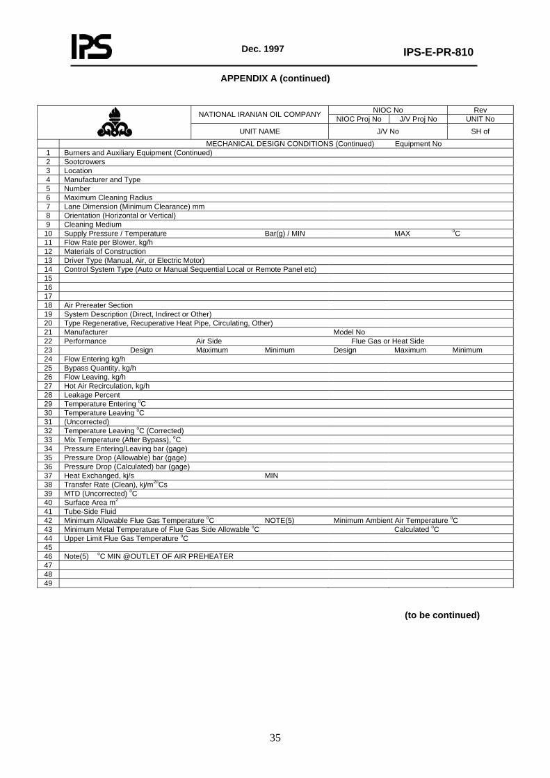
Dec. 1997
IPS-E-PR-810
35
APPENDIX A (continued)
NIOC No Rev NATIONAL IRANIAN OIL COMPANY NIOC Proj No J/V Proj No UNIT No
UNIT NAME J/V No SH of
MECHANICAL DESIGN CONDITIONS (Continued) Equipment No 1 Burners and Auxiliary Equipment (Continued) 2 Sootcrowers 3 Location 4 Manufacturer and Type 5 Number 6 Maximum Cleaning Radius 7 Lane Dimension (Minimum Clearance) mm 8 Orientation (Horizontal or Vertical) 9 Cleaning Medium
10 Supply Pressure / Temperature Bar(g) / MIN MAX oC 11 Flow Rate per Blower, kg/h 12 Materials of Construction 13 Driver Type (Manual, Air, or Electric Motor) 14 Control System Type (Auto or Manual Sequential Local or Remote Panel etc) 15 16 17 18 Air Prereater Section 19 System Description (Direct, Indirect or Other) 20 Type Regenerative, Recuperative Heat Pipe, Circulating, Other) 21 Manufacturer Model No 22 Performance Air Side Flue Gas or Heat Side 23 Design Maximum Minimum Design Maximum Minimum 24 Flow Entering kg/h 25 Bypass Quantity, kg/h 26 Flow Leaving, kg/h 27 Hot Air Recirculation, kg/h 28 Leakage Percent 29 Temperature Entering oC 30 Temperature Leaving oC 31 (Uncorrected) 32 Temperature Leaving oC (Corrected) 33 Mix Temperature (After Bypass), oC 34 Pressure Entering/Leaving bar (gage) 35 Pressure Drop (Allowable) bar (gage) 36 Pressure Drop (Calculated) bar (gage) 37 Heat Exchanged, kj/s MIN 38 Transfer Rate (Clean), kj/m2oCs 39 MTD (Uncorrected) oC 40 Surface Area m2 41 Tube-Side Fluid 42 Minimum Allowable Flue Gas Temperature oC NOTE(5) Minimum Ambient Air Temperature oC 43 Minimum Metal Temperature of Flue Gas Side Allowable oC Calculated oC 44 Upper Limit Flue Gas Temperature oC 45 46 Note(5) oC MIN @OUTLET OF AIR PREHEATER 47 48 49
(to be continued)
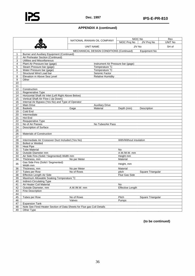
Dec. 1997
IPS-E-PR-810
36
APPENDIX A (continued)
NIOC No Rev NATIONAL IRANIAN OIL COMPANY NIOC Proj No J/V Proj No UNIT No
UNIT NAME J/V No SH of
MECHANICAL DESIGN CONDITIONS (Continued) Equipment No 1 Burner and Auxiliary Equipment (Continued) 2 Air Preheater Section (Continued) 3 Utilities and Miscellaneous 4 Plant Air Pressure bar (gage) Instrument Air Pressure bar (gage) 5 Steam Pressure bar (gage) Temperature oC 6 Water Pressure bar (gage) Temperature oC 7 Structural Wind Load bar Seismic Factor 8 Elevation m Above Sea Level Relative Humidity 9 Other
10 11 12 Construction 13 Regenerative Type 14 Horizontal Shaft Air Inlet (Left Right Above Below) 15 Vertical Shaft Air Flow ( Up Down) 16 Internal Air Bypass (Yes No) and Type of Operator 17 Main Drive Auxiliary Drive 18 Baskets Gage Material Depth (mm) Description 19 Cold End 20 Intermediate 21 Hot End 22 Requperative Type 23 No of Air Passes No Tubes/Air Pass 24 Description of Surface 25 26 Materials of Construction 27 28 Intermediate Air Crossover Duct Included (Yes No) With/Without insulation 29 Bolted or Welded 30 Heat Pipe 31 Tube Material No 32 Outside Diameter mm A.W./M.W. mm 33 Air Side Fins (Solid / Segmented) Width mm Height mm 34 Thickness, mm No per Meter Material
35 Gas Side Fins (Solid / Segmented) Width mm Height, mm
36 Thickness, mm No per Meter Material 37 Tubes per Row No of Rows pitch Square Triangular 38 Effective Length Air Side Flue Gas Side 39 Maximum Allowable Soaking Temperature oC 40 Indirect-Circulating Type 41 Air Heater Coil Material No 42 Outside Diameter, mm A.W./M.W. mm Effective Length 43 Fine Description 44 45 Tubes per Row No of Rows Pitch Square Triangular 46 Valves Pumps 47 Expansion Tank 48 Note See Fired Heater Section of Data Sheets for Flue gas Coil Details 49 Other Type
(to be continued)
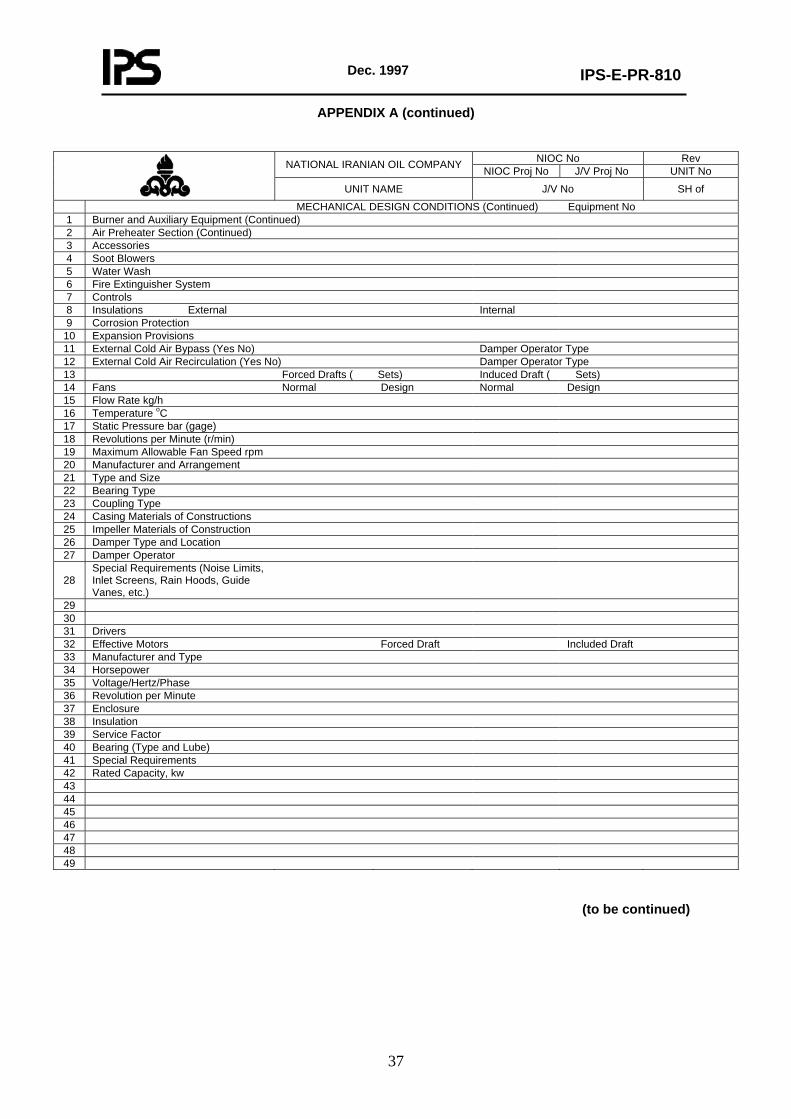
Dec. 1997
IPS-E-PR-810
37
APPENDIX A (continued)
NIOC No Rev NATIONAL IRANIAN OIL COMPANY NIOC Proj No J/V Proj No UNIT No
UNIT NAME J/V No SH of
MECHANICAL DESIGN CONDITIONS (Continued) Equipment No 1 Burner and Auxiliary Equipment (Continued) 2 Air Preheater Section (Continued) 3 Accessories 4 Soot Blowers 5 Water Wash 6 Fire Extinguisher System 7 Controls 8 Insulations External Internal 9 Corrosion Protection
10 Expansion Provisions 11 External Cold Air Bypass (Yes No) Damper Operator Type 12 External Cold Air Recirculation (Yes No) Damper Operator Type 13 Forced Drafts ( Sets) Induced Draft ( Sets) 14 Fans Normal Design Normal Design 15 Flow Rate kg/h 16 Temperature oC 17 Static Pressure bar (gage) 18 Revolutions per Minute (r/min) 19 Maximum Allowable Fan Speed rpm 20 Manufacturer and Arrangement 21 Type and Size 22 Bearing Type 23 Coupling Type 24 Casing Materials of Constructions 25 Impeller Materials of Construction 26 Damper Type and Location 27 Damper Operator
28 Special Requirements (Noise Limits, Inlet Screens, Rain Hoods, Guide Vanes, etc.)
29 30 31 Drivers 32 Effective Motors Forced Draft Included Draft 33 Manufacturer and Type 34 Horsepower 35 Voltage/Hertz/Phase 36 Revolution per Minute 37 Enclosure 38 Insulation 39 Service Factor 40 Bearing (Type and Lube) 41 Special Requirements 42 Rated Capacity, kw 43 44 45 46 47 48 49
(to be continued)
Dec. 1997
IPS-E-PR-810
38
APPENDIX A (continued)
NIOC No Rev NATIONAL IRANIAN OIL COMPANY NIOC Proj No J/V Proj No UNIT No
UNIT NAME J/V No SH of
MECHANICAL DESIGN CONDITIONS (Continued) Equipment No 1 Burner and Auxiliary Equipment (Continued) 2 Air Preheater Section (Continued) 3 Drivers (Continued) 4 Turbines Forced Draft Induced Draft 5 Manufacturer and Type of Designation 6 Horsepower Normal Condition 7 Horsepower Design Condition 8 Water Rate Normal Condition, kgh/W 9 Water Rate Design Condition, kgh/W
10 Reolutions per Minute Normal Condition 11 Reolution per Minute Design Condition 12 Steam Conditions, Inlet 13 Steam Conditions, Outlet 14 Governor 15 Bearing Type and Lube 16 Special Requirements 17 Transmission Forced Draft Induced Draft 18 Manufacturer and Type 19 Ratio 20 Service Factor 21 Lube System 22 Coupling Manufacturer and Type 23 Special Requirements (Clutches, Coupling, Guards etc.) 24 25 26 27 28 29 30 31 32 33 34 35 36 37 38 39 40 41 42 43 44 45 46 47 48 49
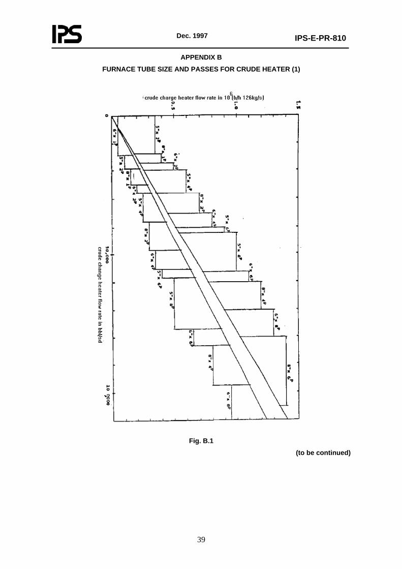
Dec. 1997
IPS-E-PR-810
39
APPENDIX B
FURNACE TUBE SIZE AND PASSES FOR CRUDE HEATER (1)
Fig. B.1
(to be continued)
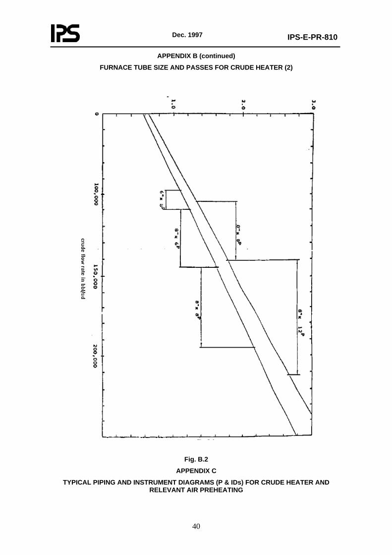
Dec. 1997
IPS-E-PR-810
40
APPENDIX B (continued)
FURNACE TUBE SIZE AND PASSES FOR CRUDE HEATER (2)
Fig. B.2
APPENDIX C
TYPICAL PIPING AND INSTRUMENT DIAGRAMS (P & IDs) FOR CRUDE HEATER AND RELEVANT AIR PREHEATING
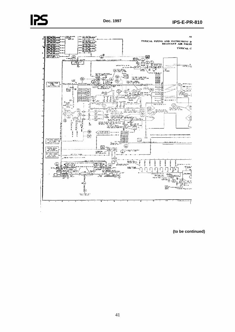
Dec. 1997
IPS-E-PR-810
41
(to be continued)
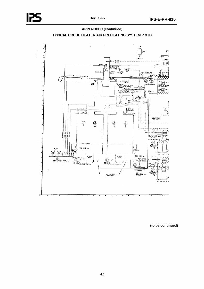
Dec. 1997
IPS-E-PR-810
42
APPENDIX C (continued)
TYPICAL CRUDE HEATER AIR PREHEATING SYSTEM P & ID
(to be continued)
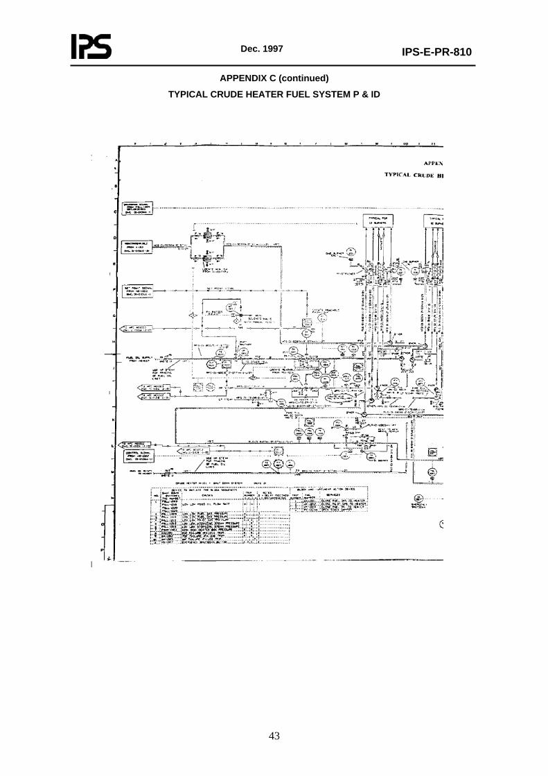
Dec. 1997
IPS-E-PR-810
43
APPENDIX C (continued)
TYPICAL CRUDE HEATER FUEL SYSTEM P & ID
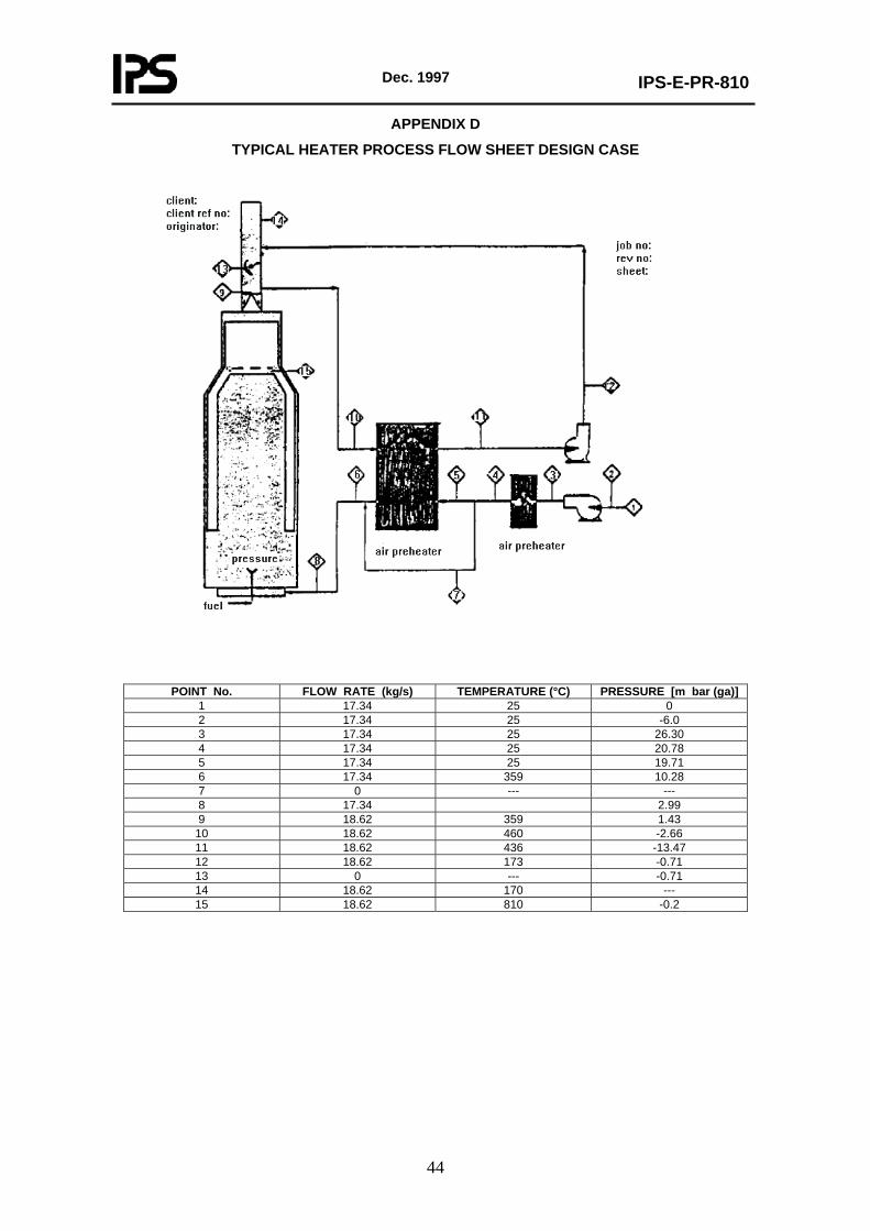
Dec. 1997
IPS-E-PR-810
44
APPENDIX D
TYPICAL HEATER PROCESS FLOW SHEET DESIGN CASE
POINT No. FLOW RATE (kg/s) TEMPERATURE (°C) PRESSURE [m bar (ga)]
1 17.34 25 0 2 17.34 25 -6.0 3 17.34 25 26.30 4 17.34 25 20.78 5 17.34 25 19.71 6 17.34 359 10.28 7 0 --- --- 8 17.34 2.99 9 18.62 359 1.43
10 18.62 460 -2.66 11 18.62 436 -13.47 12 18.62 173 -0.71 13 0 --- -0.71 14 18.62 170 --- 15 18.62 810 -0.2