Process Capability in a Computer Integrated Manufacturing Cell
71
Western Kentucky University TopSCHOLAR® Masters eses & Specialist Projects Graduate School 5-2014 Process Capability in a Computer Integrated Manufacturing Cell Andrew Austin [email protected] Follow this and additional works at: hp://digitalcommons.wku.edu/theses Part of the Computer-Aided Engineering and Design Commons , Electro-Mechanical Systems Commons , and the Manufacturing Commons is esis is brought to you for free and open access by TopSCHOLAR®. It has been accepted for inclusion in Masters eses & Specialist Projects by an authorized administrator of TopSCHOLAR®. For more information, please contact [email protected]. Recommended Citation Austin, Andrew, "Process Capability in a Computer Integrated Manufacturing Cell" (2014). Masters eses & Specialist Projects. Paper 1322. hp://digitalcommons.wku.edu/theses/1322
Transcript of Process Capability in a Computer Integrated Manufacturing Cell

Western Kentucky UniversityTopSCHOLAR®
Masters Theses & Specialist Projects Graduate School
5-2014
Process Capability in a Computer IntegratedManufacturing CellAndrew [email protected]
Follow this and additional works at: http://digitalcommons.wku.edu/theses
Part of the Computer-Aided Engineering and Design Commons, Electro-Mechanical SystemsCommons, and the Manufacturing Commons
This Thesis is brought to you for free and open access by TopSCHOLAR®. It has been accepted for inclusion in Masters Theses & Specialist Projects byan authorized administrator of TopSCHOLAR®. For more information, please contact [email protected].
Recommended CitationAustin, Andrew, "Process Capability in a Computer Integrated Manufacturing Cell" (2014). Masters Theses & Specialist Projects. Paper1322.http://digitalcommons.wku.edu/theses/1322


PROCESS CAPABILITY IN A COMPUTER
INTEGRATED MANUFACTURING CELL
A Thesis
Presented to
The Faculty of the Department of Architectural and Manufacturing Sciences
Western Kentucky University
Bowling Green, Kentucky
In Partial Fulfillment
Of the Requirements for the Degree
Master of Science
By
Andrew Austin
May 2014


I dedicate this thesis to my parents, Charles and Karen Austin, who have always given
me the support I need. I also dedicate this work to the Architecture and Manufacturing
Sciences department, as well as the entire faculty, staff, and students who made this
research possible.

iv
ACKNOWLEDGMENTS
I would like to thank several professors that made this research possible: Dr. Greg
Arbuckle, Dr. Mark Doggett, Dr. Bryan Reaka, and Dr. Muhammad Jahan. I would also
like to thank the Architecture and Manufacturing Sciences (AMS) department and
Agricultural Department for allowing me to use the facilities and equipment needed to
conduct my research. I would like to thank my AMS colleagues and staff who provided
support throughout the research process. Last I would like to thank Graduate Studies for
funding my research allowing me to purchase the necessary tools and raw material
needed to conduct my thesis.

v
CONTENTS
Introduction ......................................................................................................................... 1
Review of Literature ......................................................................................................... 14
Methodology ..................................................................................................................... 21
Findings............................................................................................................................. 33
Conclusion ........................................................................................................................ 35
Appendix A: CIM Cell...................................................................................................... 40
Appendix B: Part Data ...................................................................................................... 42
References ......................................................................................................................... 58

vi
LIST OF FIGURES
Figure 1. Horizontal bandsaw used to cut aluminum flat stock. ...................................... 22
Figure 2. Aluminum block with factory edge against base of vice. ................................ 23
Figure 3. Clamping position to machine first Y axis. ...................................................... 24
Figure 4. Processing final Y axis with aluminum block placed vertically in vice. ......... 25
Figure 5. CIM cell with loaded ASRS buffer station....................................................... 26
Figure 6. Aluminum block clamped in CNC vice. .......................................................... 27
Figure 7. Renishaw 40-2 spindle probe. .......................................................................... 29

vii
LIST OF TABLES
Table 1. Gage Repeatability Measurements. ................................................................... 31
Table 2. Process Capability Data for Six Sets of Data. ................................................... 34

viii
PROCESS CAPABILITY IN A COMPUTER
INTEGRATED MANUFACTURING CELL
Andrew Austin May 2014 59 Pages
Directed by: Greg Arbuckle, Mark Doggett, and Bryan Reaka
Department of Architectural and Manufacturing Sciences Western Kentucky University
With the rise of automation in traditional manufacturing processes, more
companies are beginning to integrate computer integrated manufacturing (CIM) cells on
their production floors. Through CIM cell integration, companies have the ability to
reduce process time and increase production. One of the problems created with CIM cell
automation is caused by the dependency the sequential steps have on one another.
Dependency created by the previous step increases the probability that a process error
could occur due to previous variation. One way to eliminate this dependency is through
the use of an in-process measuring device such as a Renishaw spindle probe used in
conjunction with a computer numerical control (CNC) milling machine.
Western Kentucky University (WKU) utilizes a CIM cell in the Senator Mitch
McConnell Advanced Manufacturing and Robotics laboratory. The laboratory is located
in the Architectural and Manufacturing Sciences department and gives students the
opportunity to learn how automated systems can be integrated. The CIM cell consists of
three Mitsubishi six-axis robots, a Haas Mini-mill, a Haas GT-10 lathe, an AXYZ, Inc.
CNC router table, 120 watt laser engraver, an Automated Storage and Retrieval System
(ASRS), material handling conveyor, and vision station. The CIM cell functions
throughout the curriculum as a means for applied learning and research. The researcher
used this CIM cell in order to determine if an in-process measuring device, such as the
Renishaw spindle probe, had the ability to affect process capability.

ix
The researcher conducted the study to see if an in-process measuring device can
be integrated into the CIM cell located in the Senator Mitch McConnell Advanced
Manufacturing and Robotics laboratory to eliminate compounding variation. The
researcher discovered that through the use of a Renishaw 40-2 spindle probe used in
conjunction with a CNC Haas Mini Mill, process capability has the potential to be
improved in a CIM cell by accounting for compounding variation present in the process.

1
Introduction
As globalization expands and new technology spreads, companies look to many
different ways to expand their business through the use of new innovative technologies.
One way that companies are remaining competitive is through the use of automation in
their manufacturing processes. With increased automation, companies have the potential
to improve upon one key business metric; increased production. Companies are
experiencing increased production because automation has the ability to save time, and
reduce scrap/rework. One downfall of the implementation of automation is that
companies fail to fully integrate the automation into the entire system. Instead, the
automation functions as an island in the manufacturing process that can lead to problems
such as bottlenecks and inefficient work flow. Since the automation is not fully
integrated, the company will be unable to reach the full potential of their automated
equipment. One way to combat islands of automation is through the use of Computer
Integrated Manufacturing (CIM). A CIM cell allows the integration of automation into
the entire manufacturing process from ordering raw materials to the production of final
goods. Process integration eliminates broken processes and is crucial to optimizing the
manufacturing environment (Saygin, 2004). By fully integrating the automation, the
company has the potential to further improve production and remain competitive (Zhou
& Chuah, 2002).
CIM has increased in popularity as companies begin to realize the full potential
CIM cells have to offer. Along with seeing the benefits CIM cells have to offer, the
increase in user friendly technology has also increased the prominence of integrated
systems. These integrated systems allow companies to use computer operating systems

2
to control manufacturing processes. One specific example is computer aided design
(CAD) and computer aided manufacturing (CAM) software that has become a vital part
of integrating computer numerical control (CNC) machining centers into CIM cells.
These two software packages have increased the user friendliness, making CNC
integration a practical approach for businesses both small and large. Overall, improved
integration software will allow more companies to use CIM cells during their
manufacturing processes (Saygin, 2004).
Universities are seeing the rise of CIM cells in manufacturing companies and are
realizing the need to train students entering the field of engineering and manufacturing on
CIM cell implementation. Many universities are actually implementing CIM cells into
their laboratories so students have the ability to learn about a CIM cell in a hands-on
manner. These CIM cells show students robots, programmable logic controllers (PLC),
CNC equipment, and computers integrated as one complete manufacturing process.
Western Kentucky University (WKU) is a prime example of a university that has
implemented a CIM cell into their Senator Mitch McConnell Advanced Manufacturing
and Robotics Laboratory. The laboratory is located in the Architectural and
Manufacturing Sciences department and gives students the opportunity to learn how
automated systems are integrated. The CIM cell consists of three Mitsubishi six-axis
robots, a Haas Mini-mill, a Haas GT-10 lathe, an AXYZ, Inc. CNC router table, 120 watt
laser engraver, an Automated Storage and Retrieval System (ASRS), material handling
conveyor, and vision station. The CIM cell functions throughout the curriculum as a
means for applied learning and research.

3
One of the main concerns with a CIM cell is that, due to complete automation,
each step is dependent on the previous step. Dependency created by the previous step
increases the probability that a process error could occur due to previous variation.
Throughout the CIM cell, each step in the process has a set amount of variation
introduced by the various inputs into the final product. Some of the inputs are; material,
operation, tooling, equipment, and program with each contributing to the variation and
process capability. The different components in the CIM cell introduce these inputs.
Integrated components in the CIM cell such as the ASRS, the ASRS robot, and the CNC
vice all introduce variation into the process.
The purpose of this research study was to determine changes in process capability
in a CIM cell through the manufacturing of a set of aluminum blocks. Process capability
was analyzed amongst six sets of data: initial process capability X, initial process
capability Y, final process capability without in-process measuring device X, final
process capability without in-process measuring device Y, final process capability with
in-process measuring device X, and final process capability with in-process measuring
device Y. Process capability is used to measure how close a process is operating within
specification requirements. As the variation decreases within a process and the
measurements become closer to the nominal value, the overall process capability will
increase. This results in a process that produces fewer defects due to less variation
present in the process (Chen, Lai, & Nien, 2010).
Problem Statement
In a CIM cell, each process is dependent on the previous step and the dependency
limits process capability. The previous step limits process capability due to the increased

4
variation that each step introduces. More variation introduced into the process causes the
process capability to continue to decrease and the dispersion to increase. In the process
capability study, a square aluminum block measuring 130mm X 130mm had a square
pocket measuring 25mm X 25mm milled in the center of the work piece by a Haas CNC
Mini-Mill. The process contained multiple steps leading up to the milling of the pocket
that increases variation and each step had the potential to diminish process capability. An
initial process capability established by the manufacturer was present due to the variation
that existed dimensionally in the aluminum blocks both in length and width. The
researcher believed that theoretically, the process capability should decrease from the
manufacturer’s process capability as the CIM cell completed each sequential step.
The process in the CIM cell started out with the ASRS that holds the aluminum
squares that had the square pocket milled in the center of the piece. The aluminum
squares used in the study were placed on pallets that were located on the ASRS. Each
pallet used six pins to locate the square aluminum blocks. Just the ASRS alone
introduced considerable variation while the aluminum blocks remained stationary.
Location of the pallets on the ASRS, location of the pins on the pallets, and pallet size all
introduced variation. The next step in the process involved the ASRS robot moving the
pallet and the square aluminum block to the buffering stage. The ASRS robot used a
sliding arm to slide under the pallets and pick up the pallets from the ASRS. Once the
ASRS robot had picked up the pallets, the ASRS placed the pallets on four locater pins
located at the buffering station. Simply moving the aluminum block from the ASRS to
the buffer station introduced a considerable amount of variation. The ASRS robot
introduced variation when it picked up the pallet due to programming deviations and

5
normal operating tolerances of the ASRS robot. The location of the four alignment pins
on the buffer station and the four alignment holes on the bottom of the pallets both added
to the variation as well. After the ASRS robot placed the pallets on the buffer station, the
Mitsubishi Robot then grabbed the aluminum block using a set of grippers. The robot
then moved down a linear slide to place the aluminum part in the vice on the CNC
milling machine. Using the grippers, the robot placed the part in the CNC vice against
two positive stops. The robot then released the part and the vice closed on the part while
the robot returned to the home position. The process of moving the aluminum blocks to
the vice also increased the variation in the CIM cell. The robot’s gripper and linear slide
already contained a tolerance established by the manufacturer that automatically
introduced variation. The location of the vice and the position of the block in the vice
also added variation. The vice could be located in the part loading position, but due to
the variation in the CNC machine, the vice was located in a slightly different place every
time. The previous stated variation is not a comprehensive list of every form of variation
that the CIM cell introduced, but the amount of variation covered shows how each
process added to an automated process introduces new variation and decreases process
capability (Hart, 1992).
The goal of the study was to measure process capability as the aluminum blocks
were processed in the CIM cell to determine changes in the initial process capability,
final process capability without the in-process measuring device, and final process
capability with the in-process measuring device. To eliminate variation, the study
proposed the use of a Renishaw 40-2 spindle probe to function as the in-process
measuring device for the CIM cell. The Renishaw probe measured the coordinate

6
positioning of the work piece to determine where the CNC milling machine created the
internal pocket. Even though the entire process consisted of integrated automated steps,
the spindle probe allowed the CNC machine to make different adjustments for each work
piece. Instead of relying on the set home position of a location pin acting as a positive
stop to position the part in the vice, the spindle probe physically measured the location of
the work piece. Physically measuring the part location with the Renishaw probe
eliminated positioning errors caused by the pallets, ASRS, ASRS robot, buffer station,
Mitsubishi robot, linear slide, and CNC vice.
Purpose of the Research
The researcher conducted a case study to determine the changes in process
capability. The study attempted to determine if the integration of the Renishaw spindle
probe functioning as an in-process measuring device had the ability to eliminate variation
in a CIM cell. If variation is eliminated through the use of the in-process measuring
device then this presents the opportunity to improve final process capability. The ability
to eliminate variation with the use of an in-process measuring device had the potential to
shed new light on the topic of process capability in a CIM cell. Conventional teaching
says that increasing final process capability over initial process capability is not possible
due to the increased variation that each step in the process introduces. Since the whole
process consisted of automated process execution, errors such as misaligned part
placement had a direct effect on the next step. Each time increased variation occurs
process capability suffers. Process capability is determined by the previous steps of the
process according to The Six Sigma Handbook, a Complete Guide for Green Belts, Black
Belts, and Managers at All Levels. The information gained from the process capability

7
study has the potential to change the traditional definition of process capability. The
knowledge gained on process capability will be useful to companies who have integrated
CNC machining centers into their CIM cells. The study showed if the integration of an
in-process measuring device had the capability to make a difference to the process
capability (Pyzdek & Keller, 2010).
By increasing process capability, the company has the potential to reduce scrap
and rework, that will save time and increase profits. The Renishaw spindle probe has the
potential to save time when integrated into a CIM cell even though using the probe adds
an extra step in the process. Time can be saved by preventing extra work from being
dedicated to scrapping parts or investing time into reworking the work piece. The
amount of time the probe can save increases with the increased complexity of the
manufactured part due to the longer machine time invested in the component. Some parts
can take several hours to machine from raw material to final product making it crucial to
prevent scrapping of parts after a large amount of time has been invested into the
machining process. Improving process capability is a vital part to Six Sigma so
improving process capability in a CIM cell will also be beneficial to companies who are
trying to increase their Sigma level. Reaching Six Sigma requires reducing defects to 3.4
defects per million opportunities. There are two ways to decrease the amount of defects
in a process: the company can extend the upper and/or lower control limit or the company
can improve the process capability (Pyzdek & Keller, 2010).
Hypothesis
H01: There was no difference between initial process capability and final process
capability without the use of the in-process measuring device.

8
H11: There was a difference between initial process capability and final process
capability without the use of the in-process measuring device.
H02: There was no difference between initial process capability and final process
capability with the use of the in-process measuring device.
H12: There was a difference between initial process capability and final process
capability with the use of the in-process measuring device.
H03: There was no difference between final process capability with the in-process
measuring device and final process capability without the in-process measuring device.
H13: There was a difference between final process capability with the in-process
measuring device and final process capability without the in-process measuring device.
The study’s objective was to measure changes in process capability to determine
the capability to eliminate variation in a CIM cell through the use of an in-process
measuring device.
Assumptions
The researcher made several assumptions about the process capability study in
order to prevent the study from becoming overbearing. Due to the capabilities of the
measuring equipment available in the Architecture and Manufacturing Sciences (AMS)
department, the study assumed that the Mitsubishi robot, the Haas CNC Mini Mill, the
ASRS, and the Renishaw 40-2 spindle probe were operating within the manufacturer’s
supplied tolerances.
Another assumption the study made directly linked with the physical make-up of
the aluminum blocks. Even though each aluminum block contained different physical
properties, the researcher made the assumption that the differences were insignificant.

9
The researcher assumed that the differences would not affect the Haas CNC Mini Mill’s
ability to machine the pocket in the aluminum block while maintaining consistent
tolerances throughout the entire machining process.
The study also assumed that normal tool wear would be minimal. When two
materials rub together, the friction created removes material from both objects. Since the
milling bit is made of high speed steel and the blocks used in the study were aluminum,
the tool wear should be minimal. Tool wear would be more significant if the study
machined a harder material like steel or cast iron. Since the tool wear was assumed to be
minimal, the Haas CNC Mini Mill was assumed to be able to maintain consistent
tolerances for the aluminum blocks while using a ¼” HSS four-fluted end mill. The end
mill was swapped out every 25 parts or whenever excessive tool fatigue occurred.
The last assumption made in the study pertained to the means used to gather the
data for the process capability study. The study assumed that the metric Mitutoyo caliper
had the ability to continuously make accurate measurements to one hundredth of a
millimeter. The researcher assumed the consistency of the Mitutoyo caliper to eliminate
the possibility that the caliper could induce inaccurate measuring errors into the study.
The study assumed this based on Mitutoyo’s supplied manufacturer specifications that
stated the accuracy of their digital caliper to be to one hundredth of a millimeter.
Limitations
The natural variation present in the study created a majority of the limitations that
the study possessed. The main variations introduced were caused by the equipment used
to carry out the manufacturing processes.

10
The RV-12SL Mitsubishi robot contained a repeatability of (±).05mm, so the
Mitsubishi robot’s consistency limited the study. Just like the Mitsubishi robot used in the
study, the Haas Mini Mill also possessed a set amount of error. The mill contained an
error measuring .01524mm in the full travel of the X-axis, and a .0127mm error in the
full travel of the Y-axis. Inspected on October 31, 2007 the manufacturer established a
set amount of error for the Haas Mini Mill, and the amount of error measured by the
manufacturer is still accurate due to the low amount of operating hours the Haas Mini
Mill contained. The ASRS also had a set amount of repeatability that factored into the
variance of the study.
Along with the limitations placed by the equipment on the study, the raw material
also placed initial limitations. The manufacturer limited the initial process capability due
to the parameters established during the manufacturing process on the aluminum blocks.
So the initial process capability was the base line for the study. Also the differing
physical properties of the 100 aluminum blocks had an effect of the tolerances the Haas
CNC Mini Mill was able to hold while machining with a ¼” four-fluted high speed steel
end mill.
Delimitations
One of the main delimitations that was placed on the study dealt with the accuracy
of the measuring equipment that was readily available in the AMS department. The
study used a digital metric Mitutoyo caliper that had the capabilities to measure to one
hundredth of a millimeter. The researcher used the digital caliper in the study to measure
the overall X and Y dimensions of the aluminum blocks, and to measure the X and Y
locations of the pocket milled in the center of the aluminum blocks. The researcher used

11
these measures to calculate initial process capability and final process capability to create
the six sets of data.
Along with the delimitations placed on the study by the measuring equipment,
there were also delimitations placed by the sample size. The study was limited to the
machining of 100 samples in order to measure initial and final process capability. The
researcher established a sample size of 100 aluminum blocks due to the limitation on raw
material. A larger sample size would increase the validity of the study, but the available
raw material limited the study.
The last set of delimitations encompassed the type of equipment used to process
the square aluminum blocks. The study used a Haas Mini Mill and a Renishaw 40-2
spindle probe. The type of equipment that was present in the AMS department created a
majority of the delimitations placed on the study.
Delimitations are not only found in the equipment used to process the material,
but also the equipment used to collect the data. MeasurLink data collection software was
used in conjunction with the Mitutoyo digital caliper to record the data points gathered in
the study. The data was then transferred from MeasurLink to Excel spread sheets.
Definition of Terms
AMS- Architecture and Manufacturing Sciences department at WKU
ASRS- An Automated Storage and Retrieval System distributes and holds
materials for post and preprocessing (Jewels, 2003).
Bottlenecks- Particular places in the manufacturing process where longer
cycle times impede the flow of the process (Dennis, 2007).

12
CAD- Computer Aided Design creates two dimensional drafting, and three
dimensional computer based models (Hagström, Ritzén, & Johansson,
2006).
CAM- Computer Aided Manufacturing generally uses CAD software to
create tool paths for a CNC machine (Thilmany, 2007).
CAPP- Computer Aided Process Planning involves the creation of
necessary planning and mapping based on customer needs (Kuhnle,
Braun, & Buhring, 1994).
CIM- Computer Integrated Manufacturing encompasses all parts of the
manufacturing process that bonded together through the integration of a
computer (Saygin, 2004).
CNC- Computer Numerical Control is using a computer to generate a code
in order to run a machine automatically (Valentino & Goldenberg, 2008,
p. 1).
DMAIC – Define, Measure, Analyze, Improve, and Control is a problem
solving strategy used in Six Sigma organizations. DMAIC is used to
define the problem, measure the process, analyze the current situation,
improve the process, and then control the improvements (Summers, 2011).
Process Capability- “The limits within which a toll or process operate
based upon minimum variability as governed by the prevailing
circumstances” (Pyzdek & Keller, 2010, p.473).

13
Robot- A programmable and repeatable machine that uses an arm to
complete a task (Ross, Fardo, Masterson & Towers, 2011).
Six Sigma- Six Sigma is a quality management program that uses statistics
to monitor quality with the goal of producing 3.4 defects or less per
million opportunities (Pyzdek & Keller, 2010).
TQC- Total Quality Control is a term coined by A. V. Feigenbaum that
looked at quality in development, maintenance, and improvement
throughout the entire company (Evans & Lindsay, 2008).
TQM- Total Quality Management, “refers to the broad set of management
and control processes designed to focus an entire organization and all of
its employees on providing products or services that do the best possible
job of satisfying the customer” (Talha, 2004).

14
Review of Literature
Process Improvement
The researcher used define, measure, analyze, improve, and control (DMAIC) in
the process capability study to design and implement the process in order to institute
continuous improvement on the CIM cell. While conducting a review of literature, a Six
Sigma study revealed the use of DMAIC to improve the process capability of an internal
process at an electronics company. Written by Drs. Hung, Wu, and Sung, the article
titled Application of Six Sigma in the TFT-LCD Industry: A Case Study discussed the
implementation of DMAIC (2011). In the TFT-LCD case study the company applied Six
Sigma by using DMAIC to a particular process in order to improve process capability.
The study used the DMAIC phases to define, measure, analyze, improve, and control the
process. The company had already identified one major defect in their manufacturing
process caused by the three components not sealing properly, resulting in a seal open
defect. The company wanted to determine if the implementation of a Six Sigma project
would result in improved process capability and process control. The company
monitored the Six Sigma success by comparing the final project results to the original
problem defined in the beginning of the project. After comparing the new number of
defects at the end of the project to the baseline data, the company was able to gain
$1,500,000 annually through the implementation of the Six Sigma project dealing with
defects caused by the three components improperly sealing.
Other companies have monitored the effects of Six Sigma project implementation
to determine if the Six Sigma quality management practice has the ability to improve an
internal process through the use of DMAIC. In the article, Using Six Sigma to Improve

15
Replenishment Process in a Direct Selling Company, Mr. Wei, Mr. Sheen, Mr. Tai, and
Mr. Lee explored the effects of implementing Six Sigma on Amway Taiwan Company.
The goal of the project was to improve the replenishment process by decreasing errors
and improving customer satisfaction. In order to improve the replenishment process, the
company formed a Six Sigma team to carry out the project by using the steps of DMAIC.
The Six Sigma team defined the problem and created a project outline that the team used
to carry out the process. The team then proceeded to the measure step in order to identify
the variables by creating a fish bone diagram by using the 6M’s (machine, measurement,
manpower, materials, Mother Nature, and methodology). After the researcher defined all
of the variables, the team determined prominent variables that had the largest effect on
the process. The Six Sigma team then proceeded to the analysis step in order to identify
variance and investigate the defined problem. Determining variance then allowed the Six
Sigma team to improve the process and maintain these improvements over an extended
period of time. When the final Six Sigma project was completed, the company measured
several metrics to determine if the project had a beneficial effect on the replenishment
process. The project resulted in a $20,000 savings along with an elimination of shipping
errors. The project also affected the planner by shortening the time the planner took to
create a replenishment plan from sixty minutes to forty minutes resulting in an increased
efficiency. Based on the Six Sigma replenishment project implementation, Six Sigma
had a positive effect on the Amway Taiwan Company (Wei, Sheen, Tai, & Lee 2010).
In-Process Measuring Device
The study attempted to determine the ability to affect process capability through
the use of a Renishaw spindle probe used in conjunction with a CNC milling machine.

16
Jim Destefani covers the use of Renishaw machine spindle probes in CNC machining in
the article titled On-Machine Probes Make Impact. Mr. Destefani specifically discussed
the use of the Renishaw probe to measure tool and part offsets. When a CNC machine
performs complex processes, several tool changes can take place in order to produce one
part. During each of these tool changes there is the potential to induce increased
variables causing the product to be either above or below the specification limits. One
way to combat tool wear is through the use of a Renishaw tool detection probe. The tool
detection probe measured tool length and diameter to determine the appropriate offsets
for the selected tool. The probe can take measurements of the tool anytime during the
production cycle. Frequent tool probe measurements allow the process to maintain
tighter tolerances on the work piece, because the probe has the ability to measure tool
wear and detect broken tools. Along with the tool probes, Renishaw has also designed
spindle probes used for pre-process, in-process, and post-process measurements of work
piece dimensions. Spindle probes have the ability to save time and reduce scrap through
their accurate measurement of work offsets. The spindle probe has the capabilities to
manually touch the part and determine the work offsets up to 1 µm. Work offsets can
eliminate part positioning errors allowing for increased dimensional accuracy. Improving
the dimensional accuracy resulted in decreased scrap rates resulting in increased
profitability. Alongside reducing scrap, the Renishaw spindle probe saves time by
reducing setup time and part measurement. Instead of manually measuring part size and
location, the probe allows the CNC program to use automation to determine the part
parameters. The CNC equipment monitors these parameters, during the run cycle to
prevent compounding of errors during the sequential steps in the process. Overall, the

17
amount of time saved and the improved quality are the two major contributions that
Renishaw probes can offer CNC manufacturing (Destefani, 2003).
CIM Cell Process Capability
The process capability study attempted to increase final process capability over
initial process capability through the use of a Renishaw CNC spindle probe. The CNC
milling machine used in the study is only one part of the entire CIM cell. In the article
Three Dimensions of CIM, Mr. Weston looked at the implications of Computer Integrated
Manufacturing (CIM) in three different subgroups; engineering, information systems, and
the operations area. Before Weston explored these three dimensions further, Weston
defined CIM as, “The automation and integration of information, processes, and
functions in a manufacturing environment, including customers and vendors, with the
result being a closed-loop, functionally integrated manufacturing planning and control
system” (Weston, 1994, p.59). The first subgroup discussed in CIM is engineering that
covers how computer aided integration is used in the planning and implementation phase
of the manufacturing process. Areas such as computer aided design, computer aided
manufacturing, and the use of integrated robots and computer numerical control
machining centers are included in the engineering subgroup. Each of these parts of
engineering are designed to function as one unit to perform complex manufacturing steps
while monitoring quality. The goal of integrating these groups is to shorten lead time
while focusing on reducing cost. The next dimension covered in the article was the use
of information systems in CIM. Information systems in CIM focus on integrating
networking and databases into the manufacturing process in order to, “link the various
elements of the organization” (Weston, 1994, p.59). Linking the elements allows

18
individual users throughout the entire company to access the same data at any given time
during the manufacturing process. The last dimension covered in the article is the use of
the operations area in CIM. According to Weston,
The third dimension of CIM speaks to the question of how products are actually
produced and placed in the hands of the customer at the time and of the quality
desired, at a reasonable price, and with total expectation that the product will
perform as designed and represented to the customer (Weston, 1994, p.60).
Some operating areas used in CIM cells are Just in Time, Material Resource Planning,
and Total Quality Management. Integration of Just in Time, Material Resource Planning,
and Total Quality Management is important in order for a CIM cell to function properly.
Keeping the areas separate will result in negative side effects and prevent the company
from maintaining a competitive edge (Weston, 1994).
With CIM cells, process capability is one of the major measures of how efficient
the process is running. In the article, Measuring Process Capability Index Cpm with
Fuzzy Data the researchers took a closer look at the different process capability measures.
According to the researchers, process capability is a vital part of decision making in a
manufacturing process. Cp and Cpk represent process capability and determine if the
products produced are within customer requirements. The researchers stated, “Process
capability indices Cp and Cpk have been used in the manufacturing industry not only to
provide numerical measures on process potential and performance, but also to quantify
the relationship between the actual process performance and the specification limits”
(Chen, Lai, & Nien, 2010, pp. 529-530). The researchers showed process capability as
listed below.

19
Cp = (USL – LSL)/ 6σ (1)
Cpk = (1 − K) × Cp (2)
K = 2 |μ − M| /(USL −LSL) (3)
M = (USL + LSL)/2 (4)
K = capability index
M = midpoint
μ = process mean
σ = standard deviation
USL = Upper Specification Limit
LSL = Lower Specification Limit
Overall these two measures Cp and Cpk determine if a process is in control and if action
needs to take place in order to move the process within acceptable control limits (Chen,
Lai, & Nien, 2010).
Researchers have realized the need to continuously monitor quality during a
manufacturing process in order to successfully implement TQM (Total Quality
Management) and TQC (Total Quality Control). Reimann and Sarkis discussed the need
for continuous quality monitoring in their article, An Architecture for Integrated
Automated Quality Control. The researchers discussed how companies are focusing on
improving CIM through the use of CAM, CAD, and CAPP, but companies are focusing
little effort on using inspection equipment to monitor quality in a CIM cell. The
incorporation of inspection equipment in an automated manufacturing cell has the ability
to improve the process and result in improvements to the product. Through the use of
integrated inspection, the equipment has the ability to monitor the quality of the part and

20
make adjustments during the process to account for in-process variations. Reimann and
Sarkis stated, “A properly integrated system enhances flexibility, increases through put,
reduces setup time, minimizes operator error, improves accuracy, improves product
quality, and lowers costs” (Reimann & Sarkis, 1993, p. 341). In order for these potential
benefits to materialize, the CIM cell must be functioning as one unit with the
incorporation of flexible inspection units. If the inspection units are operating separately
from the cell, then the equipment is unable to make adjustments and improve quality
during the manufacturing process (Reimann & Sarkis, 1993)
The review of literature gathered for this study covered many of the topics used in
this research. Companies have experienced success through the implementation of
DMAIC as a continuous improvement initiative. This showed the importance of defining
a problem within a process and the value of combating this problem by discovering the
source of the issue. Along with the information gained on process improvement, the
researcher also discovered the potential to effectively use Renishaw measuring
components as effective in-process measuring devices in conjunction with a CNC
machine. The information revealed the capability of the Renishaw measuring
components to measure variation present in the machining processes. The last area
covered in the review of literature took a closer look at CIM cell operation and how to
effectively measure a CIM cell’s capabilities. The various components covered in the
review of literature backed up the researcher’s study, even though a similar study was not
found.

21
Methodology
Procedure
In order to determine changes to process capability in a CIM cell, research was
conducted in the Senator Mitch McConnell Advanced Manufacturing and Robotics
Laboratory. The research focused around the following hypotheses:
H01: There was no difference between initial process capability and final process
capability without the use of the in-process measuring device.
H11: There was a difference between initial process capability and final process
capability without the use of the in-process measuring device.
H02: There was no difference between initial process capability and final process
capability with the use of the in-process measuring device.
H12: There was a difference between initial process capability and final process
capability with the use of the in-process measuring device.
H03: There was no difference between final process capability with the in-process
measuring device and final process capability without the in-process measuring device.
H13: There was a difference between final process capability with the in-process
measuring device and final process capability without the in-process measuring device.
To effectively research these hypotheses, a quantitative study was conducted resulting in
six sets of data. The study was conducted by processing 100 aluminum blocks in the
CIM cell without the use of the Renishaw spindle probe and then flipping the blocks over
and processing them again with the Renishaw spindle probe. Processing the aluminum
blocks in the CIM cell this way allowed the researcher to gather six sets of data: initial
process capability X, initial process capability Y, final process capability without in-

22
process measuring device X, final process capability without in-process measuring device
Y, final process capability with in-process measuring device X, and final process
capability with in-process measuring device Y.
Before the aluminum blocks were processed in the CIM cell they were
manufactured to the desired size of 130mm X 130mm. Aluminum flat stock measuring 6”
wide by 12’ long and ¾” thick was used to make the 100 aluminum blanks. Machining
the blocks to the desired size was handled by using the following equipment: a horizontal
bandsaw (see Figure 1), a waterjet, and three vertical milling machines. The first step
conducted on the aluminum flat stock was to cut the 12’ sticks into 4’ sections using the
horizontal bandsaw to help with the handling of the raw material.
Figure 1. Horizontal bandsaw used to cut aluminum flat stock.
Once the sticks were cut into 4’ sections it was then placed on the waterjet table to cut the
overall width of the material to around 135mm. Removing excess material in the width
decreased the amount of time spent on the milling machine. After all of the 4’ sections

23
were processed on the waterjet then the material was taken back to the bandsaw and cut
to around 135mm sections. This allowed the researcher to get 9 aluminum blanks out of
each 4’ stick. With the blanks now measuring roughly 135mm X 135mm, the final
machining was handled by the three manual milling machines. Due to the way the
aluminum blocks were processed, one factory edge was present on all of the blocks. This
factory edge was then used as a positive stop during the machining process on the mill
(see Figure 2). The aluminum blocks were placed vertically in the vice with the factory
edge against the base of the vice.
Figure 2. Aluminum block with factory edge against base of vice.
A positive stop was placed in the Z axis allowing the operator to take several passes on
the aluminum blank until it reached the final dimension of 130mm. With the X
dimension within the desired specification, the Y dimension was processed next. The
part was then clamped in the vice with the jaws applying pressure to the two parallel X

24
sides (see Figure 3). One of the Y sides was then machined perpendicular to the X axis
to true up the edge.
Figure 3. Clamping position to machine first Y axis.
With three sides processed, the forth side was machined in the mill to bring the Y axis to
its final specification. The block was then placed vertically in the vice with the
previously processed Y axis resting against the base of the vice (see Figure 4).

25
Figure 4. Processing final Y axis with aluminum block placed vertically in vice.
A positive stop used in the Z axis allowed the operator to machine the block to 130mm in
the Y axis.
With the blocks machined to 130mm X 130mm, they were next processed in the
CIM cell. A rendering of the CIM cell shows a general view of the cell layout (see
Appendix A). One side of the aluminum blocks was processed with the use of the
Renishaw spindle probe, the other side without the Renishaw spindle probe. In order to
run the blocks, the ASRS was loaded with the 100 aluminum blocks and processed in the
CIM cell without the use of the Renishaw spindle probe. Due to the holding capacity of
the ASRS, the ASRS was loaded in sets in order to run all 100 blocks. The process
started with the ASRS robot picking up the pallet that the aluminum block was resting on,
and moving the pallet to a buffering station. Once the aluminum block was loaded onto
the buffer station; the Mitsubishi robot moved into position to grab the aluminum block
from the pallet. The Mitsubishi robot used a set of grippers to grab the aluminum block
26
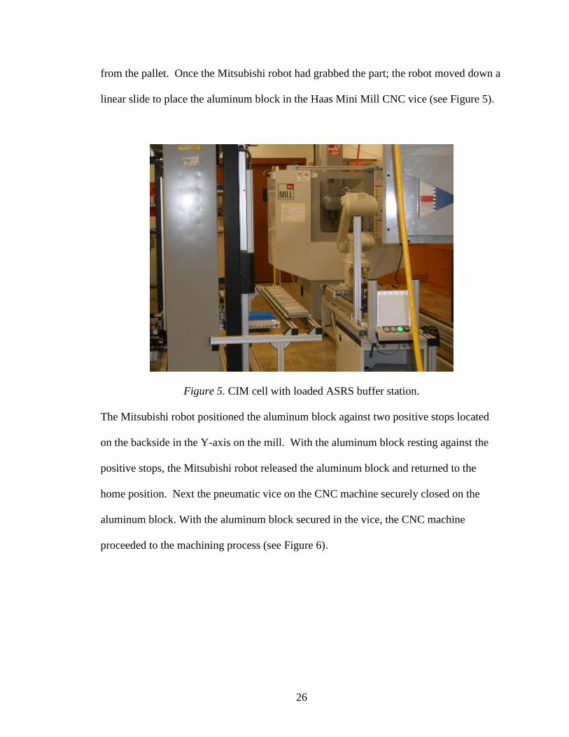
from the pallet. Once the Mitsubishi robot had grabbed the part; the robot moved down a
linear slide to place the aluminum block in the Haas Mini Mill CNC vice (see Figure 5).
Figure 5. CIM cell with loaded ASRS buffer station.
The Mitsubishi robot positioned the aluminum block against two positive stops located
on the backside in the Y-axis on the mill. With the aluminum block resting against the
positive stops, the Mitsubishi robot released the aluminum block and returned to the
home position. Next the pneumatic vice on the CNC machine securely closed on the
aluminum block. With the aluminum block secured in the vice, the CNC machine
proceeded to the machining process (see Figure 6).
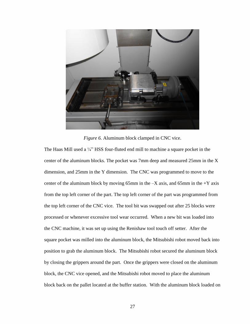
27
Figure 6. Aluminum block clamped in CNC vice.
The Haas Mill used a ¼” HSS four-fluted end mill to machine a square pocket in the
center of the aluminum blocks. The pocket was 7mm deep and measured 25mm in the X
dimension, and 25mm in the Y dimension. The CNC was programmed to move to the
center of the aluminum block by moving 65mm in the –X axis, and 65mm in the +Y axis
from the top left corner of the part. The top left corner of the part was programmed from
the top left corner of the CNC vice. The tool bit was swapped out after 25 blocks were
processed or whenever excessive tool wear occurred. When a new bit was loaded into
the CNC machine, it was set up using the Renishaw tool touch off setter. After the
square pocket was milled into the aluminum block, the Mitsubishi robot moved back into
position to grab the aluminum block. The Mitsubishi robot secured the aluminum block
by closing the grippers around the part. Once the grippers were closed on the aluminum
block, the CNC vice opened, and the Mitsubishi robot moved to place the aluminum
block back on the pallet located at the buffer station. With the aluminum block loaded on

28
the pallet located at the buffer station, the ASRS robot moved into position to pick up the
pallet and placed the pallet back on the ASRS. The process continued to repeat itself
until the 100 aluminum blocks were machined. Once the blocks were machined, final
process capability was recorded (see Appendix B).
With the CIM cell process described, the problem with process capability became
prominent. The researcher defined the problem in the study to encompass process
capability in a CIM cell. Process capability is defined as the problem because in a CIM
cell, initial process capability of the work piece affects the final process capability of the
work piece. A direct effect is created by initial process capability because each step is
dependent on the previous. The dependency created causes each step to introduce more
variation into the process. Increased variation causes final process capability to decrease
preventing the final process capability from exceeding initial process capability.
Decreased process capability caused by increased variation can be detrimental to the final
product causing the product to fall outside the upper or lower specification limits
established by the customer. The study planned to combat the problem of increased
variation through the use of an in-process measuring device. The measuring device, a
Renishaw 40-2 CNC spindle probe (see Figure 7), was used to measure the exact
coordinate positioning of a part in the CNC vice.

29
Figure 7. Renishaw 40-2 spindle probe.
Instead of programming the center of the aluminum block off of the top right corner of
the vice, the researcher used the spindle probe to measure the true center of the aluminum
block. The true center of the aluminum block was found by measuring the distance
between the four sides of the aluminum block with the Renishaw spindle probe. The
Renishaw spindle probe touched X1 and the X2 and measured the length and divided this
measurement by two. The probe then did the same thing for the two Y side of the
aluminum block. By measuring the exact coordinate positioning and finding the true
center of the aluminum block, previous variation caused by positioning error and
variation in initial size of the aluminum blocks was eliminated. Along with the
integration of the probe, the tool was also monitored before machining each block by
measuring the tool wear with a Renishaw tool touch off setter. The researcher used the
Renishaw spindle probe to determine the ability to increase final process capability over

30
initial process capability and increase final process capability over the group of aluminum
blocks processed in the CIM cell without the use of the probe.
In order to measure and gather the six sets of data used in the study, the researcher
used a Mitutoyo caliper to measure the X and Y dimensions. The Mitutoyo caliper
measured to one hundredth of a millimeter and was used in conjunction with MeasurLink
Real Time Plus. MeasurLink Real Time Plus is a measuring computer software that was
directly wired to a Mitutoyo caliper with a communication cable. The software allowed
the Mitutoyo caliper to transfer measurements from the caliper to the computer with the
push of a foot pedal. The MeasurLink had an integrated foot pedal switch that
automatically implemented measurements into the measuring software. By using the
MeasurLink software linked with the Mitutoyo caliper, user error by manually writing in
the numbers was eliminated.
A gage calibration study was conducted to determine if the Mitutoyo caliper were
still operating within their measuring capabilities. Generally when a gage study is
conducted, it is carried out as an r&r study that represents repeatability and
reproducibility. For this research it was not necessary to ensure reproducibility because
there was only one operator using the caliper to measure the components. Repeatability
was important in order to validate the true data that was collected. The caliper was
calibrated using a set of standard cera gage blocks manufactured by Mitutoyo. The cera
blocks were certified on June 15, 2005. This certification data was still valid due to the
low amount of time the cera blocks had been used. The cera blocks were used once a
year for instructional purposes only. Since the cera blocks were in standard
measurement, the researcher used a 1’’ cera block and converted the measurement to

31
25.4mm. To validate the caliper, the researcher measured the cera block ten times. The
data gathered was placed in a table (see Table 1).
Table 1
Gage Repeatability Measurements
Attempt Length (mm)
1 25.4
2 25.4
3 25.4
4 25.4
5 25.4
6 25.4
7 25.4
8 25.4
9 25.4
10 25.4
The repeatability was measured by placing the data in following formula in order
to calculate the accuracy of the Mitutoyo caliper:
Accuracy = Xbarm – X (5)
Xbarm = measurement length average
X = actual size of cera block
When the data was plugged into formula (5), the researcher discovered that the accuracy
was +/- 0.00mm. This signified that the digital caliper was able to accurately measure
within one hundredth of a millimeter. This assured the researcher that the Mitutoyo
digital caliper was not introducing unaccounted error into the study (Sahay, 2012).
Once the caliper was determined to be operating within its proper specifications,
the researcher used the caliper to measure the blocks in order to gather the data needed to
calculate process capability. The data gathered was then placed in a table (see Appendix

32
B). The initial process capability was calculated by using the measures gathered in
regards to the X and Y dimensions of the 100 aluminum blocks. The formula (1) was
used to calculate the Cp for the aluminum blocks established by the manufacturer in both
the X and Y dimension. A Cpk was also calculated for the aluminum blocks supplied by
the manufacturer using formulas (2), (3), and (4) in both the X and Y dimension. The
final process capability with the in-process measuring device and the final process
capability without the in-process measuring device were calculated using the same
formulas (1), (2), (3), and (4). The only difference is how the process capability was
measured in regards to the X and Y dimensions used to calculate the process capability.
The final capability measure was based on how close the square pocket was milled into
the center of the aluminum block in both the X and Y dimension. The researcher took
X1-X2 and Y1-Y2 and these measures were centered on the nominal value of 0mm. The
Cp and Cpk was used to determine if the Renishaw spindle probe had a direct effect on
process capability in the study when analyzed in regards to: initial process capability X,
initial process capability Y, final process capability without in-process measuring device
X, final process capability without in-process measuring device Y, final process
capability with in-process measuring device X, and final process capability with in-
process measuring device Y.

33
Findings
After all the data was collected using the Measurlink software, the data was
transferred to Microsoft Excel to determine the process capability for the various
parameters measured in this study. Descriptive statistics were calculated for the six sets
of 100 data points (initial process capability X, initial process capability Y, final process
capability without in-process measuring device X, final process capability without in-
process measuring device Y, final process capability with in-process measuring device X,
and final process capability with in-process measuring device Y.). These descriptive
statistics were then used to calculate Cp and Cpk using the formulas mentioned in the
review of literature:
Cp = (USL – LSL)/ 6σ (1)
Cpk = (1 − K) × Cp (2)
K = 2 |μ − M| /(USL −LSL) (3)
M = (USL + LSL)/2 (4)
K = capability index
M = midpoint
μ = process mean
σ = standard deviation
USL = Upper Specification Limit
LSL = Lower Specification Limit
Collecting descriptive statistics on the data collected was vital to gathering the
appropriate information to calculate Cp and Cpk. The numbers gathered were then
placed in the formula to calculate the Cp and Cpk (Chen, Lai, & Nien, 2010). The results

34
gathered from the study were organized in a table to easily see the changes in the process
capability amongst the six sets of data (see Table 2).
Table 2
Process Capability Data for Six Sets of Data
Data Sets X Y
Cp = 7.1915
Cpk = 7.1570
Cp = 2.7500
Cpk = 2.6975
Initial Process Capability
Final Process Capability Without
Probe
Cp = .61874
Cpk = .56280
Cp = 1.4780
Cpk = .96571
Final Process Capability With Probe
Cp = 3.9399
Cpk = 3.5199
Cp = 3.8446
Cpk = 3.0053

35
Conclusion
After gathering the results from this study, the researcher was able to come to a
conclusion about the previous stated hypotheses. Based on the Cp and Cpk results the
researcher was able to accept the first research hypothesis:
H11: There was a difference between initial process capability and final process
capability without the use of the in-process measuring device.
The first research hypothesis was accepted based on the change that occurred in the
process capability from the initial capability to the final capability without the use of the
in-process measuring device. When the in-process measuring device was not in use, the
added variation introduced by the CIM cell caused the process capability of the work
piece to decrease (see Table 2).
The data collected also revealed that the researcher could retain the second
research hypothesis.
H12: There was a difference between initial process capability and final process
capability with the use of the in-process measuring device.
The study showed that the Renishaw spindle probe was able to measure and account for
variation that was introduced by previous steps. This allowed the CNC mini mill to
machine the internal pocket in the center of the aluminum block at greater dimensional
accuracy (see Table 2).
When the researcher analyzed the results based on the third set of hypotheses, it
was more challenging to gather a conclusive result. The set of blocks processed with the
Renishaw spindle probe in the X axis showed a decrease in process capability while the
Y axis showed an increase in process capability when compared to the initial process

36
capability of the aluminum blocks. This result was linked to the extremely high initial
process capability in the X axis (see Table 2). As stated in the methodology, only one of
the X axis sides was machined during the initial machining process to create the
aluminum blanks. This translated into all of the blocks retaining one factory edge in the
X axis resulting in less variation being introduced to the overall width in the X axis. Due
to less variation present in the X axis, the initial process capability was substantially
higher than the Y axis.
The Renishaw spindle probe showed a difference for the process capability in
both the X axis and the Y axis. The process capability for the Y axis improved, while the
process capability for the X axis decreased so the researcher was able to retain the second
research hypothesis. The ability to improve the process capability over the initial
variation established by the raw material was shown with the improvement in the final
process capability in the Y axis. The results showed that there was a limit in the amount
of variation that the Renishaw spindle probe was able to operate within. This was shown
in the decrease of the final process capability in the X axis.
H13: There was a difference between final process capability with the in-process
measuring device and final process capability without the in-process measuring device.
The data collected on the third research hypothesis showed that the Renishaw spindle
probe had the capability to eliminate variation and improve the machining capabilities of
the CNC machine. The drastic improvement in Cp and Cpk shown in both the X and Y
axis allowed the researcher to accept the third research hypothesis.
After the researcher analyzed the data collected and studied the results in regard
to the three sets of hypotheses, the researcher was able to conclude that process capability

37
decreased in the CIM cell due to the compounding variation introduced by each piece of
linked automation. The researcher discovered that, in order to account for this
compounding variation, a Renishaw spindle probe could act as an in-process measuring
device. The in-process measuring device allowed the CNC machine to account for the
previous variation introduced in the system and adjust accordingly. Individually
adjusting the machining process for all of the aluminum blanks allowed the final process
capability to improve over the initial process capability. This showed that the process
was able to create a part containing less variation than initially present in the raw
material.
Suggestions for Further Research
In order to revalidate the information gathered from this research it is important
that the research be completed again while focusing on a few areas that could possibly
cause unintended variation. Revalidating the data collected will help prove that the
Renishaw spindle probe was able to improve the process capability within the CIM cell.
The first area that could be adjusted in future studies is the way that tool wear was
monitored. An issue occurred with tool breakage while machining the 100 aluminum
blocks without the use of the Renishaw spindle probe. Tools breaking caused the amount
of tool wear that each block experienced without the probe to vary. In order to eliminate
the varying tool wear experienced during the machining process, the tool touch off setter
could be used the same way it was used on the blocks processed with the Renishaw
spindle probe. Before each block was machined, the tool could be measured with the tool
touch off probe. This would eliminate the issue of varying tool wear between the sets of

38
blocks processed with and without the probe, while still determining if the Renishaw
spindle probe had the capability to eliminate compound process variation.
Another area of variation that could be more closely monitored in future studies is
the means used to measure the aluminum blocks. Instead of using an individual to
measure all of the data with a digital caliper, a jig could be used to eliminate human
variation that was introduced into the study. If the caliper was held incorrectly during a
measurement, the measurement was retaken by the operator, but there is still the potential
to introduce an incorrect measurement into the study. If a jig was used that would
prevent the operator from introducing human measuring error into the study, the data
would increase in validity.
Along with these issues there was also a problem with the vice that prevented the
robot from consistently loading the aluminum blocks in the cell. Over time, the
vibrations present in the CNC milling machine prevented the jaws on the vice from
opening to their full reach. This restriction on the opening of the jaws caused the robot to
incorrectly load the aluminum blocks. When the blocks were incorrectly loaded, the CIM
cell had to be shut down and restarted. Since the CIM cell had to be restarted each time
the robot incorrectly loaded the part, this prevented the CIM cell from running the desired
batch size without restarting the cell. Constantly restarting the cell could have introduced
unexpected variation into the data that could be eliminated in future studies now that the
vice has been repaired.
The last revision that could be made in future studies deals with the X side
retaining one of the factor edges. The researcher attributed the high initial process
capability in the X axis to the fewer number of steps that were present when processing

39
the aluminum blocks on the X axis. If both sides of the X axis were processed on the
manual milling machine then the process capability would more closely resemble the
initial process capability of the Y axis. In future studies, the same steps used to process
the Y axis should be used to process the X axis to ensure a more consistent initial process
capability for the work piece.

40
Appendix A: CIM Cell

41

42
Appendix B: Part Data

43
Initial Process Capability (mm)
Part
Number
X
Dimension
Y
Dimension USL LSL
Nominal
Dimension
1 129.96 129.99 131 129 130
2 129.97 129.97 131 129 130
3 130.01 130.00 131 129 130
4 130.02 130.08 131 129 130
5 130.00 129.94 131 129 130
6 130.01 130.07 131 129 130
7 130.01 129.93 131 129 130
8 130.00 130.07 131 129 130
9 130.07 130.02 131 129 130
10 129.98 129.99 131 129 130
11 130.05 129.96 131 129 130
12 129.93 129.98 131 129 130
13 129.99 130.01 131 129 130
14 130.04 129.96 131 129 130
15 129.81 130.06 131 129 130
16 130.05 129.99 131 129 130
17 129.95 129.96 131 129 130
18 129.92 130.04 131 129 130
19 130.04 129.98 131 129 130
20 130.02 129.94 131 129 130
21 130.07 129.95 131 129 130
22 130.14 130.00 131 129 130
23 130.00 130.03 131 129 130
24 130.03 129.95 131 129 130
25 130.08 130.07 131 129 130
26 130.13 129.99 131 129 130
27 130.11 130.03 131 129 130
28 129.92 130.00 131 129 130
29 129.97 129.97 131 129 130
30 130.10 129.93 131 129 130
31 130.03 129.93 131 129 130
32 130.06 129.97 131 129 130
33 130.03 130.01 131 129 130
34 129.81 130.02 131 129 130
35 130.03 129.89 131 129 130
36 130.02 129.98 131 129 130
37 130.01 130.00 131 129 130
38 129.92 129.98 131 129 130
39 130.01 130.02 131 129 130
40 130.00 129.94 131 129 130

44
41 129.96 129.99 131 129 130
42 130.04 130.00 131 129 130
43 129.99 129.97 131 129 130
44 130.05 130.05 131 129 130
45 129.99 129.98 131 129 130
46 129.92 130.00 131 129 130
47 129.99 130.04 131 129 130
48 130.03 130.10 131 129 130
49 129.98 130.09 131 129 130
50 130.05 130.03 131 129 130
51 129.92 129.90 131 129 130
52 129.99 129.97 131 129 130
53 129.97 130.00 131 129 130
54 130.00 130.00 131 129 130
55 130.20 130.02 131 129 130
56 129.99 130.02 131 129 130
57 129.90 129.98 131 129 130
58 129.97 130.08 131 129 130
59 129.96 130.04 131 129 130
60 130.04 129.99 131 129 130
61 129.90 130.04 131 129 130
62 129.96 129.96 131 129 130
63 130.04 130.00 131 129 130
64 129.02 129.95 131 129 130
65 129.97 129.98 131 129 130
66 129.96 130.02 131 129 130
67 129.87 130.01 131 129 130
68 129.89 129.99 131 129 130
69 129.99 130.08 131 129 130
70 129.98 129.97 131 129 130
71 130.00 129.91 131 129 130
72 129.95 129.98 131 129 130
73 129.94 130.01 131 129 130
74 129.96 129.99 131 129 130
75 130.10 129.98 131 129 130
76 129.93 130.03 131 129 130
77 129.99 129.99 131 129 130
78 129.87 129.96 131 129 130
79 129.99 129.98 131 129 130
80 130.03 129.95 131 129 130
81 130.04 130.02 131 129 130
82 129.96 130.03 131 129 130
83 129.92 130.04 131 129 130

45
84 130.02 129.93 131 129 130
85 130.04 129.97 131 129 130
86 129.94 129.97 131 129 130
87 129.87 129.99 131 129 130
88 130.11 130.16 131 129 130
89 130.00 129.97 131 129 130
90 130.02 129.99 131 129 130
91 129.98 129.95 131 129 130
92 129.96 130.01 131 129 130
93 130.03 129.92 131 129 130
94 130.02 130.08 131 129 130
95 130.10 130.01 131 129 130
96 129.97 129.92 131 129 130
97 129.90 129.99 131 129 130
98 130.02 129.96 131 129 130
99 129.92 129.99 131 129 130
100 129.69 129.99 131 129 130

46
Final Process Capability Y Dimension Without the Probe
(mm)
Part
Number Y1 Dimension Y2 Dimension
Y1-
Y2 USL LSL
Nominal
Dimension
1 52.17 52.83 -0.66 1 -1 0.00
2 53.39 51.66 1.73 1 -1 0.00
3 52.55 52.53 0.02 1 -1 0.00
4 52.37 52.66 -0.29 1 -1 0.00
5 51.95 53.07 -1.12 1 -1 0.00
6 52.72 52.27 0.45 1 -1 0.00
7 52.36 52.72 -0.36 1 -1 0.00
8 52.50 52.39 0.11 1 -1 0.00
9 52.70 52.40 0.30 1 -1 0.00
10 52.66 52.41 0.25 1 -1 0.00
11 52.84 52.26 0.58 1 -1 0.00
12 52.72 52.26 0.46 1 -1 0.00
13 52.74 52.34 0.40 1 -1 0.00
14 52.60 52.60 0.00 1 -1 0.00
15 52.64 52.34 0.30 1 -1 0.00
16 52.45 52.66 -0.21 1 -1 0.00
17 52.55 52.51 0.04 1 -1 0.00
18 52.65 52.35 0.30 1 -1 0.00
19 52.57 52.47 0.10 1 -1 0.00
20 52.58 52.45 0.13 1 -1 0.00
21 53.07 51.89 1.18 1 -1 0.00
22 52.84 52.15 0.69 1 -1 0.00
23 52.81 52.04 0.77 1 -1 0.00
24 52.71 52.32 0.39 1 -1 0.00
25 53.12 51.97 1.15 1 -1 0.00
26 52.44 52.54 -0.10 1 -1 0.00
27 52.61 52.50 0.11 1 -1 0.00
28 52.65 52.37 0.28 1 -1 0.00
29 52.91 52.09 0.82 1 -1 0.00
30 52.61 52.46 0.15 1 -1 0.00
31 52.50 52.57 -0.07 1 -1 0.00
32 51.95 53.05 -1.10 1 -1 0.00
33 52.71 52.41 0.30 1 -1 0.00
34 52.81 52.38 0.43 1 -1 0.00
35 52.49 52.50 -0.01 1 -1 0.00
36 52.70 52.33 0.37 1 -1 0.00
37 52.61 52.21 0.40 1 -1 0.00
38 52.54 52.56 -0.02 1 -1 0.00
39 52.28 52.75 -0.47 1 -1 0.00

47
40 52.54 52.50 0.04 1 -1 0.00
41 52.43 52.59 -0.16 1 -1 0.00
42 52.65 52.36 0.29 1 -1 0.00
43 52.54 52.45 0.09 1 -1 0.00
44 52.65 52.54 0.11 1 -1 0.00
45 52.58 52.50 0.08 1 -1 0.00
46 52.64 52.44 0.20 1 -1 0.00
47 52.54 52.40 0.14 1 -1 0.00
48 52.82 52.34 0.48 1 -1 0.00
49 52.71 52.33 0.38 1 -1 0.00
50 52.28 52.70 -0.42 1 -1 0.00
51 52.17 52.99 -0.82 1 -1 0.00
52 52.73 52.35 0.38 1 -1 0.00
53 52.63 52.41 0.22 1 -1 0.00
54 52.34 52.64 -0.30 1 -1 0.00
55 52.63 52.45 0.18 1 -1 0.00
56 52.52 52.58 -0.06 1 -1 0.00
57 52.67 52.49 0.18 1 -1 0.00
58 52.55 52.50 0.05 1 -1 0.00
59 51.87 53.24 -1.37 1 -1 0.00
60 52.72 52.37 0.35 1 -1 0.00
61 52.43 52.76 -0.33 1 -1 0.00
62 52.71 52.37 0.34 1 -1 0.00
63 52.55 52.49 0.06 1 -1 0.00
64 52.73 52.26 0.47 1 -1 0.00
65 52.29 52.75 -0.46 1 -1 0.00
66 52.41 52.66 -0.25 1 -1 0.00
67 53.17 51.89 1.28 1 -1 0.00
68 52.60 52.50 0.10 1 -1 0.00
69 52.17 52.80 -0.63 1 -1 0.00
70 52.73 52.30 0.43 1 -1 0.00
71 52.83 52.27 0.56 1 -1 0.00
72 52.43 52.65 -0.22 1 -1 0.00
73 52.65 52.44 0.21 1 -1 0.00
74 52.49 52.62 -0.13 1 -1 0.00
75 52.48 52.70 -0.22 1 -1 0.00
76 53.18 51.84 1.34 1 -1 0.00
77 52.94 52.09 0.85 1 -1 0.00
78 52.47 52.62 -0.15 1 -1 0.00
79 52.16 52.92 -0.76 1 -1 0.00
80 52.30 52.77 -0.47 1 -1 0.00
81 52.78 52.31 0.47 1 -1 0.00
82 52.22 52.82 -0.60 1 -1 0.00

48
83 52.20 52.92 -0.72 1 -1 0.00
84 52.54 52.46 0.08 1 -1 0.00
85 52.68 52.40 0.28 1 -1 0.00
86 52.61 52.49 0.12 1 -1 0.00
87 52.70 52.32 0.38 1 -1 0.00
88 52.43 52.63 -0.20 1 -1 0.00
89 52.21 52.77 -0.56 1 -1 0.00
90 52.54 52.54 0.00 1 -1 0.00
91 52.80 52.29 0.51 1 -1 0.00
92 52.16 53.03 -0.87 1 -1 0.00
93 52.44 52.73 -0.29 1 -1 0.00
94 52.06 52.97 -0.91 1 -1 0.00
95 52.54 52.41 0.13 1 -1 0.00
96 52.51 52.47 0.04 1 -1 0.00
97 53.31 51.78 1.53 1 -1 0.00
98 52.50 52.53 -0.03 1 -1 0.00
99 52.56 52.50 0.06 1 -1 0.00
100 52.42 52.66 -0.24 1 -1 0.00

49
Final Process Capability X Dimension Without the Probe
(mm)
Part
Number X1 Dimension X2 Dimension
X1-
X2 USL LSL
Nominal
Dimension
1 52.76 52.25 0.51 1 -1 0.00
2 52.84 52.26 0.58 1 -1 0.00
3 52.75 52.45 0.30 1 -1 0.00
4 52.57 52.52 0.05 1 -1 0.00
5 52.68 52.53 0.15 1 -1 0.00
6 52.84 52.24 0.60 1 -1 0.00
7 52.55 52.57 -0.02 1 -1 0.00
8 52.72 52.36 0.36 1 -1 0.00
9 52.85 52.32 0.53 1 -1 0.00
10 52.79 52.50 0.29 1 -1 0.00
11 52.51 52.47 0.04 1 -1 0.00
12 52.54 52.52 0.02 1 -1 0.00
13 52.50 52.58 -0.08 1 -1 0.00
14 52.83 52.29 0.54 1 -1 0.00
15 52.54 52.62 -0.08 1 -1 0.00
16 52.52 52.48 0.04 1 -1 0.00
17 52.60 52.39 0.21 1 -1 0.00
18 52.58 52.45 0.13 1 -1 0.00
19 52.71 52.37 0.34 1 -1 0.00
20 52.72 52.17 0.55 1 -1 0.00
21 52.65 52.43 0.22 1 -1 0.00
22 52.84 52.26 0.58 1 -1 0.00
23 52.59 52.50 0.09 1 -1 0.00
24 52.72 52.18 0.54 1 -1 0.00
25 52.81 52.33 0.48 1 -1 0.00
26 52.73 52.30 0.43 1 -1 0.00
27 52.99 52.14 0.85 1 -1 0.00
28 52.59 52.22 0.37 1 -1 0.00
29 52.76 52.33 0.43 1 -1 0.00
30 52.61 52.37 0.24 1 -1 0.00
31 52.60 52.46 0.14 1 -1 0.00
32 52.59 52.40 0.19 1 -1 0.00
33 52.75 52.24 0.51 1 -1 0.00
34 52.61 52.53 0.08 1 -1 0.00
35 52.77 52.40 0.37 1 -1 0.00
36 52.63 52.35 0.28 1 -1 0.00
37 52.77 52.11 0.66 1 -1 0.00
38 52.76 52.28 0.48 1 -1 0.00
39 52.60 52.43 0.17 1 -1 0.00

50
40 52.58 52.41 0.17 1 -1 0.00
41 52.53 52.46 0.07 1 -1 0.00
42 52.80 52.26 0.54 1 -1 0.00
43 52.52 52.31 0.21 1 -1 0.00
44 52.70 52.21 0.49 1 -1 0.00
45 52.84 52.13 0.71 1 -1 0.00
46 52.55 52.44 0.11 1 -1 0.00
47 52.80 52.37 0.43 1 -1 0.00
48 53.00 52.11 0.89 1 -1 0.00
49 52.65 52.45 0.20 1 -1 0.00
50 52.79 52.17 0.62 1 -1 0.00
51 52.65 52.27 0.38 1 -1 0.00
52 52.56 52.52 0.04 1 -1 0.00
53 52.81 52.32 0.49 1 -1 0.00
54 52.56 52.55 0.01 1 -1 0.00
55 52.55 52.46 0.09 1 -1 0.00
56 52.52 52.45 0.07 1 -1 0.00
57 52.85 52.16 0.69 1 -1 0.00
58 52.61 52.49 0.12 1 -1 0.00
59 52.81 52.48 0.33 1 -1 0.00
60 52.48 52.45 0.03 1 -1 0.00
61 52.66 52.31 0.35 1 -1 0.00
62 52.87 52.35 0.52 1 -1 0.00
63 52.55 52.41 0.14 1 -1 0.00
64 52.76 52.29 0.47 1 -1 0.00
65 52.65 52.47 0.18 1 -1 0.00
66 52.59 52.41 0.18 1 -1 0.00
67 52.68 52.43 0.25 1 -1 0.00
68 52.71 52.38 0.33 1 -1 0.00
69 52.87 52.26 0.61 1 -1 0.00
70 52.75 52.29 0.46 1 -1 0.00
71 52.87 52.24 0.63 1 -1 0.00
72 52.85 52.25 0.60 1 -1 0.00
73 52.75 52.23 0.52 1 -1 0.00
74 52.68 52.49 0.19 1 -1 0.00
75 52.64 52.37 0.27 1 -1 0.00
76 52.61 52.48 0.13 1 -1 0.00
77 52.87 52.20 0.67 1 -1 0.00
78 52.64 52.43 0.21 1 -1 0.00
79 52.82 52.24 0.58 1 -1 0.00
80 52.67 52.42 0.25 1 -1 0.00
81 52.84 52.18 0.66 1 -1 0.00
82 52.76 52.25 0.51 1 -1 0.00

51
83 52.51 52.43 0.08 1 -1 0.00
84 52.64 52.38 0.26 1 -1 0.00
85 52.79 52.18 0.61 1 -1 0.00
86 52.65 52.38 0.27 1 -1 0.00
87 52.37 51.88 0.49 1 -1 0.00
88 52.77 52.14 0.63 1 -1 0.00
89 52.62 52.41 0.21 1 -1 0.00
90 52.70 52.26 0.44 1 -1 0.00
91 52.56 52.41 0.15 1 -1 0.00
92 52.59 52.38 0.21 1 -1 0.00
93 52.85 52.28 0.57 1 -1 0.00
94 52.79 52.19 0.60 1 -1 0.00
95 52.83 52.16 0.67 1 -1 0.00
96 52.78 52.25 0.53 1 -1 0.00
97 52.66 52.50 0.16 1 -1 0.00
98 52.90 52.18 0.72 1 -1 0.00
99 52.65 52.38 0.27 1 -1 0.00
100 52.67 52.45 0.22 1 -1 0.00

52
Final Process Capability Y Dimension With the Probe
(mm)
Part
Number Y1 Dimension Y2 Dimension
Y1-
Y2 USL LSL
Nominal
Dimension
1 52.52 52.54 -0.02 1 -1 0.00
2 52.42 52.57 -0.15 1 -1 0.00
3 52.43 52.60 -0.17 1 -1 0.00
4 52.52 52.56 -0.04 1 -1 0.00
5 52.43 52.58 -0.15 1 -1 0.00
6 52.39 52.62 -0.23 1 -1 0.00
7 52.40 52.53 -0.13 1 -1 0.00
8 52.40 52.60 -0.20 1 -1 0.00
9 52.47 52.55 -0.08 1 -1 0.00
10 52.66 52.49 0.17 1 -1 0.00
11 52.52 52.67 -0.15 1 -1 0.00
12 52.48 52.60 -0.12 1 -1 0.00
13 52.42 52.62 -0.20 1 -1 0.00
14 52.39 52.67 -0.28 1 -1 0.00
15 52.46 52.64 -0.18 1 -1 0.00
16 52.37 52.67 -0.30 1 -1 0.00
17 52.50 52.51 -0.01 1 -1 0.00
18 52.50 52.55 -0.05 1 -1 0.00
19 52.40 52.51 -0.11 1 -1 0.00
20 52.42 52.52 -0.10 1 -1 0.00
21 52.42 52.56 -0.14 1 -1 0.00
22 52.42 52.52 -0.10 1 -1 0.00
23 52.38 52.51 -0.13 1 -1 0.00
24 52.42 52.59 -0.17 1 -1 0.00
25 52.43 52.49 -0.06 1 -1 0.00
26 52.44 52.52 -0.08 1 -1 0.00
27 52.42 52.69 -0.27 1 -1 0.00
28 52.52 52.63 -0.11 1 -1 0.00
29 52.41 52.54 -0.13 1 -1 0.00
30 52.45 52.50 -0.05 1 -1 0.00
31 52.44 52.64 -0.20 1 -1 0.00
32 52.47 52.56 -0.09 1 -1 0.00
33 52.41 52.55 -0.14 1 -1 0.00
34 52.50 52.50 0.00 1 -1 0.00
35 52.45 52.55 -0.10 1 -1 0.00
36 52.40 52.61 -0.21 1 -1 0.00
37 52.48 52.56 -0.08 1 -1 0.00
38 52.52 52.56 -0.04 1 -1 0.00
39 52.51 52.50 0.01 1 -1 0.00

53
40 52.47 52.53 -0.06 1 -1 0.00
41 52.45 52.56 -0.11 1 -1 0.00
42 52.56 52.49 0.07 1 -1 0.00
43 52.45 52.52 -0.07 1 -1 0.00
44 52.43 52.58 -0.15 1 -1 0.00
45 52.40 52.56 -0.16 1 -1 0.00
46 52.42 52.58 -0.16 1 -1 0.00
47 52.44 52.60 -0.16 1 -1 0.00
48 52.48 52.52 -0.04 1 -1 0.00
49 52.42 52.57 -0.15 1 -1 0.00
50 52.43 52.53 -0.10 1 -1 0.00
51 52.46 52.50 -0.04 1 -1 0.00
52 52.43 52.61 -0.18 1 -1 0.00
53 52.41 52.63 -0.22 1 -1 0.00
54 52.45 52.67 -0.22 1 -1 0.00
55 52.42 52.54 -0.12 1 -1 0.00
56 52.42 52.61 -0.19 1 -1 0.00
57 52.37 52.50 -0.13 1 -1 0.00
58 52.40 52.40 0.00 1 -1 0.00
59 52.40 52.48 -0.08 1 -1 0.00
60 52.40 52.60 -0.20 1 -1 0.00
61 52.48 52.63 -0.15 1 -1 0.00
62 52.41 52.61 -0.20 1 -1 0.00
63 52.40 52.53 -0.13 1 -1 0.00
64 52.45 52.59 -0.14 1 -1 0.00
65 52.47 52.71 -0.24 1 -1 0.00
66 52.44 52.68 -0.24 1 -1 0.00
67 52.43 52.48 -0.05 1 -1 0.00
68 52.49 52.45 0.04 1 -1 0.00
69 52.42 52.58 -0.16 1 -1 0.00
70 52.56 52.62 -0.06 1 -1 0.00
71 52.58 52.51 0.07 1 -1 0.00
72 52.47 52.59 -0.12 1 -1 0.00
73 52.64 52.54 0.10 1 -1 0.00
74 52.44 52.63 -0.19 1 -1 0.00
75 52.47 52.62 -0.15 1 -1 0.00
76 52.54 52.64 -0.10 1 -1 0.00
77 52.61 52.65 -0.04 1 -1 0.00
78 52.38 52.64 -0.26 1 -1 0.00
79 52.45 52.58 -0.13 1 -1 0.00
80 52.49 52.59 -0.10 1 -1 0.00
81 52.60 52.55 0.05 1 -1 0.00
82 52.48 52.54 -0.06 1 -1 0.00

54
83 52.50 52.55 -0.05 1 -1 0.00
84 52.48 52.63 -0.15 1 -1 0.00
85 52.51 52.60 -0.09 1 -1 0.00
86 52.46 52.53 -0.07 1 -1 0.00
87 52.57 52.55 0.02 1 -1 0.00
88 52.42 52.46 -0.04 1 -1 0.00
89 52.54 52.60 -0.06 1 -1 0.00
90 52.45 52.53 -0.08 1 -1 0.00
91 52.41 52.54 -0.13 1 -1 0.00
92 52.41 52.56 -0.15 1 -1 0.00
93 52.48 52.58 -0.10 1 -1 0.00
94 52.63 52.61 0.02 1 -1 0.00
95 52.45 52.61 -0.16 1 -1 0.00
96 52.54 52.57 -0.03 1 -1 0.00
97 52.53 52.55 -0.02 1 -1 0.00
98 52.42 52.51 -0.09 1 -1 0.00
99 52.53 52.57 -0.04 1 -1 0.00
100 52.44 52.56 -0.12 1 -1 0.00

55
Final Process Capability X Dimension With the Probe
(mm)
Part
Number X1 Dimension X2 Dimension
X1-
X2 USL LSL
Nominal
Dimension
1 52.55 52.31 0.24 1 -1 0.00
2 52.67 52.43 0.24 1 -1 0.00
3 52.69 52.46 0.23 1 -1 0.00
4 52.73 52.57 0.16 1 -1 0.00
5 52.68 52.42 0.26 1 -1 0.00
6 52.59 52.43 0.16 1 -1 0.00
7 52.78 52.39 0.39 1 -1 0.00
8 52.61 52.61 0.00 1 -1 0.00
9 52.68 52.46 0.22 1 -1 0.00
10 52.74 52.46 0.28 1 -1 0.00
11 52.65 52.38 0.27 1 -1 0.00
12 52.65 52.43 0.22 1 -1 0.00
13 52.68 52.39 0.29 1 -1 0.00
14 52.65 52.34 0.31 1 -1 0.00
15 52.71 52.47 0.24 1 -1 0.00
16 52.64 52.36 0.28 1 -1 0.00
17 52.77 52.24 0.53 1 -1 0.00
18 52.73 52.45 0.28 1 -1 0.00
19 52.61 52.49 0.12 1 -1 0.00
20 52.62 52.34 0.28 1 -1 0.00
21 52.64 52.64 0.00 1 -1 0.00
22 52.63 52.43 0.20 1 -1 0.00
23 52.72 52.50 0.22 1 -1 0.00
24 52.61 52.40 0.21 1 -1 0.00
25 52.61 52.42 0.19 1 -1 0.00
26 52.59 52.42 0.17 1 -1 0.00
27 52.57 52.50 0.07 1 -1 0.00
28 52.67 52.42 0.25 1 -1 0.00
29 52.55 52.35 0.20 1 -1 0.00
30 52.57 52.47 0.10 1 -1 0.00
31 52.63 52.44 0.19 1 -1 0.00
32 52.57 52.43 0.14 1 -1 0.00
33 52.62 52.47 0.15 1 -1 0.00
34 52.55 52.34 0.21 1 -1 0.00
35 52.56 52.35 0.21 1 -1 0.00
36 52.57 52.39 0.18 1 -1 0.00
37 52.61 52.41 0.20 1 -1 0.00
38 52.60 52.39 0.21 1 -1 0.00
39 52.64 52.36 0.28 1 -1 0.00

56
40 52.64 52.34 0.30 1 -1 0.00
41 52.66 52.39 0.27 1 -1 0.00
42 52.65 52.43 0.22 1 -1 0.00
43 52.60 52.38 0.22 1 -1 0.00
44 52.71 52.40 0.31 1 -1 0.00
45 52.61 52.41 0.20 1 -1 0.00
46 52.59 52.32 0.27 1 -1 0.00
47 52.58 52.38 0.20 1 -1 0.00
48 52.57 52.44 0.13 1 -1 0.00
49 52.51 52.34 0.17 1 -1 0.00
50 52.58 52.51 0.07 1 -1 0.00
51 52.63 52.34 0.29 1 -1 0.00
52 52.57 52.35 0.22 1 -1 0.00
53 52.59 52.40 0.19 1 -1 0.00
54 52.61 52.40 0.21 1 -1 0.00
55 52.53 52.40 0.13 1 -1 0.00
56 52.57 52.40 0.17 1 -1 0.00
57 52.71 52.35 0.36 1 -1 0.00
58 52.63 52.42 0.21 1 -1 0.00
59 52.73 52.43 0.30 1 -1 0.00
60 52.32 52.03 0.29 1 -1 0.00
61 52.78 52.47 0.31 1 -1 0.00
62 52.54 52.28 0.26 1 -1 0.00
63 52.67 52.45 0.22 1 -1 0.00
64 52.75 52.52 0.23 1 -1 0.00
65 52.55 52.34 0.21 1 -1 0.00
66 52.58 52.51 0.07 1 -1 0.00
67 52.63 52.39 0.24 1 -1 0.00
68 52.75 52.39 0.36 1 -1 0.00
69 52.64 52.41 0.23 1 -1 0.00
70 52.58 52.42 0.16 1 -1 0.00
71 52.61 52.43 0.18 1 -1 0.00
72 52.59 52.45 0.14 1 -1 0.00
73 52.61 52.37 0.24 1 -1 0.00
74 52.60 52.45 0.15 1 -1 0.00
75 52.61 52.51 0.10 1 -1 0.00
76 52.65 52.40 0.25 1 -1 0.00
77 52.62 52.44 0.18 1 -1 0.00
78 52.60 52.37 0.23 1 -1 0.00
79 52.61 52.40 0.21 1 -1 0.00
80 52.75 52.43 0.32 1 -1 0.00
81 52.79 52.43 0.36 1 -1 0.00
82 52.78 52.43 0.35 1 -1 0.00

57
83 52.61 52.34 0.27 1 -1 0.00
84 52.84 52.39 0.45 1 -1 0.00
85 52.62 52.50 0.12 1 -1 0.00
86 52.49 52.45 0.04 1 -1 0.00
87 52.53 52.50 0.03 1 -1 0.00
88 52.54 52.45 0.09 1 -1 0.00
89 52.68 52.53 0.15 1 -1 0.00
90 52.65 52.43 0.22 1 -1 0.00
91 52.62 52.42 0.20 1 -1 0.00
92 52.57 52.37 0.20 1 -1 0.00
93 52.63 52.35 0.28 1 -1 0.00
94 52.56 52.35 0.21 1 -1 0.00
95 52.67 52.43 0.24 1 -1 0.00
96 52.62 52.35 0.27 1 -1 0.00
97 52.57 52.32 0.25 1 -1 0.00
98 52.55 52.36 0.19 1 -1 0.00
99 52.59 52.41 0.18 1 -1 0.00
100 52.67 52.34 0.33 1 -1 0.00

58
References
Cheng-Che Chen, Chun-Mei Lai, & Hsiao-Yu Nien. (2010). Measuring process
capability index C pm with fuzzy data. Quality and Quantity, 44(3), 529-535
Dennis, P. (2007). Lean production simplified. (2 ed., pp. 1-12). New York: Productivity
Press
Destefani, J. (2003). On-machine probes make impact. Manufacturing Engineering,
130(1)
Evans, J. R., & Lindsay, W. M. (2008). Managing for quality and performance
excellence. (7th ed.). Mason, OH: Thomson South-Western.
Hagström, L., Ritzén, S., & Johansson, J. (2006). The use and implementation of CAD in
the swedish furniture industry. Forest Products Journal, 56(1), 73-81\
Hart, M. K. (1992). Quality tools for decreasing variation and defining process capability.
Production and Inventory Management Journal, 33(2), 6-6
Hung, H., Wu, T., & Sung, M. (2011). Application of six sigma in the tft-lcd industry: A
case study. International Journal of Organizational Innovation (Online), 4(1), 74-
93
Jewels, T. (2003). The dag-brucken ASRS case study. Journal of Information Systems
Education, 14(3), 247-257
Kuhnle, H., Braun, H., & Buhring, J. (1994). Integration of CAPP and PPC - interfusion
manufacturing management. Integrated Manufacturing Systems, 5(2), 21-21.
Pyzdek, T., & Keller, P. A. (2010). The six sigma handbook, a complete guide for green
belts, black belts, and managers at all levels. (3rd ed.). McGraw-Hill
Professional.

59
Reimann, M. D., & Sarkis, J. (1993). An architecture for integrated automated quality
control. Journal of Manufacturing Systems, 12(4), 341-341
Ross, L., Fardo, S., Masterson, J., & Towers, R. (2011). Robotics theory and industrial
applications. (2nd ed., pp. 11-58). Tinley Park, Illinois: The Goodheart-Willcox
Company, Inc.
Sahay, A. (2012). Six sigma quality: Concepts & cases. (Vol. 1). Sandy, UT: QMS
Global LLC.
Saygin, C. (2004). A Manufacturing laboratory for integrated hands-on applications.
American Society for Engineering, 1-15
Summers, D. C. (2011). Lean six sigma. (1 ed., pp. 81-96). Upper Saddle River, New
Jersey: Prentice Hall.
Talha, M. (2004). Total quality management (TQM): An overview. The Bottom Line,
17(1), 15-19
Thilmany, J. (2007). Where does CAM stand? Mechanical Engineering, 129(1), 30-32
Valentino, J., & Goldenberg, J. (2008). Introduction to computer numerical control (cnc).
(4th ed., pp. 1-11). Upper Saddle River, New Jersey: Pearson Prentice Hall.
Wei, C., Sheen, G., Tai, C., & Lee, K. (2010). Using six sigma to improve replenishment
process in a direct selling company. Supply Chain Management, 15(1), 3-9
Weston, F. C. J. (1994). Three dimensions of CIM. Production and Inventory
Management Journal, 35(1), 59-59
Zhou, Y., & Chuah, K. B. (2002). Computer-integrated manufacturing in china: A report
of industrial field surveys. International Journal of Operations & Production
Management, 22(3), 271-288