PROCESS AUTOMATION -...
58
Manual FD0-VC-Ex4.PA PROCESS AUTOMATION Valve Coupler for PROFIBUS PA
Transcript of PROCESS AUTOMATION -...

Manual
FD0-VC-Ex4.PA
PROC
ESS
AUTO
MAT
ION
Valve Coupler for PROFIBUS PA

PROFIBUS-PA Valve Coupler FD0-VC-Ex4.PA
Part N
o.: 0
5434
0, D
ate
of is
sue
4.04
.201
4
1 SAFETY........................................................................................................................... 31.1 Scope of the Manual.................................................................................................................................. 31.2 Validity ........................................................................................................................................................ 31.3 Symbols Used............................................................................................................................................ 31.4 System Operator and Personnel.............................................................................................................. 41.5 Pertinent Laws, Standards, Directives, and further Documentation.................................................... 41.6 Marking....................................................................................................................................................... 41.7 Intended Use.............................................................................................................................................. 41.8 Mounting and Installation......................................................................................................................... 5
1.8.1 General ..................................................................................................................................... 51.9 Ambient Temperature ............................................................................................................................... 51.10 Repair and Maintenance ........................................................................................................................... 51.11 Delivery, Transport and Storage.............................................................................................................. 51.12 Disposal...................................................................................................................................................... 5
2 PRODUCT DESCRIPTION ............................................................................................. 62.1 Scope of Delivery ...................................................................................................................................... 62.2 System Structure....................................................................................................................................... 6
2.2.1 Device Description .................................................................................................................... 72.2.2 Description of Communication .................................................................................................. 92.2.3 Connecting Auxiliary Valves ..................................................................................................... 92.2.4 Connecting Final Position Feedback Contacts ......................................................................... 92.2.5 Description of 2:1 Procedure..................................................................................................... 9
2.3 Accessories ............................................................................................................................................. 10
3 INSTALLATION ............................................................................................................ 113.1 Assembly.................................................................................................................................................. 113.2 Electrical Connection.............................................................................................................................. 13
3.2.1 General Notes for Connection ................................................................................................ 133.2.2 Connection of PROFIBUS PA ................................................................................................. 143.2.3 Connection of Auxiliary Valves and Final Position Feedback Contacts................................... 143.2.4 EMC, Shielding, Grounding .................................................................................................... 16
4 INTRODUCTION FOR COMMISSIONING (PARAMETERIZATION, CONFIGURATION) ....................................................................................................... 17
4.1 System Requirements for Commissioning........................................................................................... 174.2 General Information on Commissioning............................................................................................... 174.3 Checklist for Commissioning................................................................................................................. 18
5 PARAMETERIZATION.................................................................................................. 195.1 General ..................................................................................................................................................... 195.2 Parameterization of the Device Specific Characteristics.................................................................... 21
5.2.1 Set PROFIBUS Address ......................................................................................................... 215.2.1.1 Setting a Fxed Address without Modification Feature via Bus ..........................................................215.2.1.2 Setting an address with modification feature via bus ........................................................................21
5.2.2 Setting the PROFIBUS Ident Number ..................................................................................... 225.2.3 Setting the Documentation Parameters .................................................................................. 225.2.4 Other Device Parameters for Specific Devices ....................................................................... 22
5.3 Parameterization of the Channel-Specific Characteristics ................................................................. 235.3.1 Responses of the Output to the Setpoint Value ...................................................................... 23
5.3.1.1 Introduction to the User Data Structure and Importance of the Setpoint Value .................................235.3.1.2 Introduction to the Operating Modes (Parameter Target Mode)........................................................245.3.1.3 Behavior in "Auto" Operation Mode, Case of Fault ...........................................................................255.3.1.4Behavior of the Device in the "RCas" Operation Mode ........................................................................26
5.3.2 Parameters Concerning Actuator and Final Position Feedback .............................................. 275.3.2.1 Actuator Fail Action (Mechanical Safety Position).............................................................................27
1Subject to reasonable modifications due to technical advances. Copyright Pepperl+Fuchs, Printed in Germany
Pepperl+Fuchs Group • Tel.: Germany +49-621-776-0 • USA +1-330-4253555 • Singapore +65-67-799091 • Internet www.pepperl-fuchs.com

PROFIBUS-PA Valve Coupler FD0-VC-Ex4.PA
Par
t No.
: 054
340,
Dat
e of
issu
e 4.
04.2
014
5.3.2.2 Sensor Mode ................................................................................................................................... 275.3.3 Channel Specific Parameters for Diagnosis ............................................................................28
5.3.3.1 Wire Check ...................................................................................................................................... 285.3.3.2 Stroke Counter................................................................................................................................. 285.3.3.3 Time Monitoring ............................................................................................................................... 285.3.3.4 Cyclic Function Test......................................................................................................................... 30
5.3.4 Setting the Documentation Parameters...................................................................................305.4 Write Protection ....................................................................................................................................... 31
6 CONFIGURATION.........................................................................................................326.1 General ..................................................................................................................................................... 326.2 Log in Valve Coupler at DP Master ........................................................................................................ 326.3 Installation of GSD File ........................................................................................................................... 326.4 Select Module Identifiers ........................................................................................................................ 326.5 Example of Configuration ....................................................................................................................... 346.6 Description of User Data......................................................................................................................... 34
6.6.1 General ...................................................................................................................................346.6.2 Arrangement of the Status of SP_D, RB_D, RIN_D and ROUT_D..........................................346.6.3 Variable SP_D.........................................................................................................................356.6.4 Variable RIN_D .......................................................................................................................366.6.5 Variable RB_D ........................................................................................................................366.6.6 Variable ROUT_D ...................................................................................................................376.6.7 Variable CB_D ........................................................................................................................37
6.7 Description of Slave Diagnosis .............................................................................................................. 38
7 OPERATION..................................................................................................................397.1 Manual Operating Mode.......................................................................................................................... 39
7.1.1 Initialization Run......................................................................................................................397.1.2 Sequence................................................................................................................................397.1.3 Direct Setpoint Value Specification .........................................................................................39
7.2 Simulation................................................................................................................................................. 39
8 DIAGNOSIS AND ERROR CORRECTION ...................................................................408.1 General ..................................................................................................................................................... 408.2 LEDs.......................................................................................................................................................... 408.3 Functional Check without Connected Valves ....................................................................................... 418.4 Possible Faults during the Initialization Run (section 7.1.1) .............................................................. 428.5 Status information from RB_D ............................................................................................................... 428.6 Status informations from ROUT_D ........................................................................................................ 438.7 Variable CB_D .......................................................................................................................................... 438.8 Slave diagnosis........................................................................................................................................ 45
9 APPENDIX.....................................................................................................................469.1 Parameter Reference List ....................................................................................................................... 46
9.1.1 Legend....................................................................................................................................469.1.2 Device-Related Parameters ....................................................................................................469.1.3 Channel-Related Parameter (Channel 1 ... 4), Identification and Output.................................489.1.4 Channel-Related Parameters (Channel 1 ... 4), Characteristics of Actuator (Drive)
and Regulation Unit.................................................................................................................509.2 Literature .................................................................................................................................................. 549.3 Glossary ................................................................................................................................................... 55
2Subject to reasonable modifications due to technical advances. Copyright Pepperl+Fuchs, Printed in Germany
Pepperl+Fuchs Group • Tel.: Germany +49-621-776-0 • USA +1-330-4253555 • Singapore +65-67-799091 • Internet www.pepperl-fuchs.com

PROFIBUS PA Valve Coupler FD0-VC-Ex4.PASafety
Part N
o.: 05
4340
, Date
of is
sue 4
.04.20
14
1 Safety1.1 Scope of the Manual
This manual enables the user to install, start, operate, and parameterize the Valve Coupler. In addition, it pro-vides all necessary information of the status/fault messages, device safety and monitoring functions and of fault diagnosis and fault elimination.
1.2 ValidityThe chapter “Safety” is valid as instruction manual.Specific processes and instructions in this document require special precautions to guarantee the safety of the operating personnel.
1.3 Symbols UsedThis document contains information that you must read for your own personal safety and to avoid property damage. Depending on the hazard category, the warning signs are displayed in descending order as follows:
Safety-relevant symbols
Informative symbols
Some sections of the manual require special knowledge and experience in the field of explosion protection, as well as planning, design, and implementation of fieldbus systems with the PROFIBUS PA, i.e., there is no introduction into the PROFIBUS for newcomers or inexperienced users for space reasons. For further information refer to the bibliography in the appendix and the relevant literature and publications of PROFIBUS Nutzerorganisation e.V. (www.profibus.com).
Within this manual reference is made to the bibliography. These references are given in the form /3/.
In addition, many terms and abbreviations used in this manual are explained in the appendix.
•
This symbol indicates a warning about a possible danger.In the event the warning is ignored, the consequences may range from personal injury to death or from damage to equipment to destruction.
•
This symbol warns of a possible fault. Failure to observe the instructions given in this warning may result in the device and any connected facilities or systems to it develop a fault or fail completely.
This symbol brings important information to your attention.
3Subject to reasonable modifications due to technical advances. Copyright Pepperl+Fuchs, Printed in Germany
Pepperl+Fuchs Group • Tel.: Germany +49-621-776-0 • USA +1-330-4253555 • Singapore +65-67-799091 • Internet www.pepperl-fuchs.com

PROFIBUS PA Valve Coupler FD0-VC-Ex4.PASafety
Part N
o.: 05
4340
, Date
of is
sue 4
.04.20
14
1.4 System Operator and PersonnelThe plant owner is responsible for its planning, installation, commissioning, operation, maintenance and di-sassembly.Mounting, installation, commissioning, operation, maintenance and disassembly of any devices may only be carried out by trained, qualified personnel. The instruction manual must be read and understood.
1.5 Pertinent Laws, Standards, Directives, and further DocumentationLaws, standards, or directives applicable to the intended use must be observed. In relation to hazardous areas, Directive 1999/92/EC must be observed.The corresponding data sheets, declarations of conformity, EC-type-examination certificates, certificates and Control Drawings if applicable (see datasheet) are an integral part of this document. You can find this information under www.pepperl-fuchs.com.Due to constant revisions, documentation is subject to permanent change. Please refer only to the most up-to-date version, which can be found under www.pepperl-fuchs.com.
1.6 MarkingThe following identification is provided on the Valve Coupler FD0-VC-Ex4.PA:Pepperl+Fuchs GmbHD-68307 Mannheim
FD0-VC-Ex4.PACE 0102PTB 98 ATEX 2210
II 2G (1) Ex ia [ia Ga] IIC T4 GbII (1D) [Ex ia Da] IIIC
IECEx TUN 04.0002 Ex ia [ia Ga] IIC T4 Gb[Ex ia Da] IIICEx ic IIC T4 Gc[Ex ic Dc] IIIC
1.7 Intended UseThe Valve Coupler FD0-VC-Ex4.**** is a field devices for connection to an intrinsically safe PROFIBUS PA fieldbus.The FD0-VC-Ex4.**** is used to operate intrinsically safe low power auxiliary valves and their final position feedback contacts.The Valve Coupler FD0-VC-Ex4.**** is used in type of protection II 2G (1) Ex ia [ia Ga] IIC T4 Gb.
The protection of operators and plant is not ensured, unless the device is used for the purpose intended.
4Subject to reasonable modifications due to technical advances. Copyright Pepperl+Fuchs, Printed in Germany
Pepperl+Fuchs Group • Tel.: Germany +49-621-776-0 • USA +1-330-4253555 • Singapore +65-67-799091 • Internet www.pepperl-fuchs.com

PROFIBUS PA Valve Coupler FD0-VC-Ex4.PASafety
Part N
o.: 05
4340
, Date
of is
sue 4
.04.20
14
1.8 Mounting and InstallationWhen using intrinsically safe devices in accordance with IEC/EN 60079-11, follow the EC-type-examination certificate and the national regulations for installations. Reference should be made to IEC/EN 60079-14 for the interconnection of the intrinsically safe circuits. In the Federal Republic of Germany reference should also be made to the "National foreword" to DIN 60079-14/VDE 0165 Part 1.The Valve Coupler FD0-VC-Ex4.PA is designed for use in potentially explosive atmospheres. The respective maximum values of the field devices and of the Valve Coupler must be considered in the sense of explosion protection (demonstration of intrinsic safety) when interconnecting the intrinsically safe field devices (auxili-ary valves, sensors, vibrating forks, etc.) with the intrinsically safe circuits of the Valve Coupler.The fieldbus connection is a certified, intrinsically safe circuit, in accordance with the FISCO and the Entity model.When interconnected according to the FISCO model, all the field devices and associated apparatus (fieldbus repeaters) connected to this segment must be certified in accordance with the FISCO model.
1.8.1 GeneralMounting, installation, commissioning, operation, maintenance and disassembly of any devices may only be carried out by trained, qualified personnel. The instruction manual must be read and understood.If devices have already been operated in general electrical systems, they may subsequently no longer be in-stalled in electrical systems used in combination with hazardous areas.In case the Valve Coupler has been operated in the type of protection “Ex ic”, it must not be operated in the type of protection “Ex ia” or “Ex ib” afterwards.The datasheet containing the electrical data from the EC-type-examination certificate respectively the IECEx Certificate of Conformity and additional technical information is effectively a part of this operating instruction.
1.9 Ambient TemperatureThe device may be operated at an ambient temperature ranging from -20 °C ... +70 °C .
1.10 Repair and MaintenanceThe devices must not be repaired, changed or manipulated. If there is a defect, the product must always be replaced with an original device.
1.11 Delivery, Transport and StorageCheck the packaging and contents for damage. Check if you have received every item and if the items received are the ones you ordered.Keep the original packaging. Always store and transport the device in the original packaging.Always store the device in a clean and dry environment. The permitted storage temperature (see data sheet) must be considered.
1.12 DisposalDisposing of devices, packaging material, and possibly contained batteries must be in compliance with the applicable laws and guidelines of the respective country.
5Subject to reasonable modifications due to technical advances. Copyright Pepperl+Fuchs, Printed in Germany
Pepperl+Fuchs Group • Tel.: Germany +49-621-776-0 • USA +1-330-4253555 • Singapore +65-67-799091 • Internet www.pepperl-fuchs.com

PROFIBUS PA Valve Coupler FD0-VC-Ex4.PAProduct Description
Part N
o.: 05
4340
, Date
of is
sue 4
.04.20
14
2 Product Description2.1 Scope of Delivery
Included in the delivery package of the device are:• A device FD0-VC-Ex4.PA• One product attachment (instruction manual, data sheet)The following parts are not included in the delivery package of the device, however, can be requested free of charge up to the number of devices ordered:• Manual, German and English, incl. data carrier (disk 3,5" or CD) with GSD file and DTM driver
2.2 System StructureThe Valve Coupler FD0-VC-Ex4.PA is a field device for system structure PROFIBUS PA complying to the FISCO model. A maximum of four intrinsically safe low power auxiliary valves and a maximum of eight final position feedback contacts (PFCs; NAMUR sensors or other mechanical contacts) can be connected within areas subject to explosion hazards or areas that are not subject to explosion hazards. An auxiliary valve is used as a pilot valve for one actuator that can be provided with limit position feedback contacts to feed back the drive position. The term “valve“ as used in this manual means the overall chain consisting of auxiliary val-ve and actuator.PROFIBUS PA and the connected devices are supplied by a Segment Coupler that is also the interface bet-ween the areas subject to explosion hazard and not subject to explosion hazard.For PROFIBUS PA a shielded twisted two-wire cable is used. Via this two-wire cable the field devices are supplied and data is exchanged. PROFIBUS PA allows branches as shown in figure 2.1.
Figure 2.1: The Valve Coupler FD0-VC-Ex4.PA at PROFIBUS PA
Other accessories see section 2.3 and product catalog of Pepperl+Fuchs.
For further information of PROFIBUS PA and important notes for planning and design, please refer to /4/.
Supply
Segment coupler
[EEx ia]
Bus termination-Resistance
Valve couplerFD0-VC-Ex4.PA
RS485
(PLC/PLS)Control system
Field Devices
Up to four intrinsically safeLow-Power auxiliary valves
and up to eight PFCs
(Bus termination switched on)
PROFIBUS PA (IEC 61158-2)PROFIBUS-DP
6Subject to reasonable modifications due to technical advances. Copyright Pepperl+Fuchs, Printed in Germany
Pepperl+Fuchs Group • Tel.: Germany +49-621-776-0 • USA +1-330-4253555 • Singapore +65-67-799091 • Internet www.pepperl-fuchs.com

PROFIBUS PA Valve Coupler FD0-VC-Ex4.PAProduct Description
Part N
o.: 05
4340
, Date
of is
sue 4
.04.20
14
2.2.1 Device DescriptionThe Valve Coupler is accommodated in a housing for panel mounting. This housing may also be mounted at a pipeline using specific accessories. The side of the device provides 14 digit barcode. This barcode is the serial number of the device, and enables the clear identification of the device:
The device has been designed for the type of protection "intrinsic safety" and can be positioned in the field upon approval. The connector terminals of the fieldbus are spatially and galvanically separated from those of the auxiliary valves and PFCs. LEDs on top of the terminal blocks locally indicate the instantaneous status of the Valve Coupler.• PWR (power): green (continuous light) = supply voltage available• COM/ERR: red (continuous light) = Hardware fault
red (flashing) = no bus activity or bus fault• IN/OUT CHK: red (continuous light) = Fault code for a hardware fault detected during acceleration.
red (flashing) = channel fault; for the cause of the fault refer to section 8.
For the wiring and evaluation of the final position feedbacks the 2:1 procedure is used which is described in more detail in section 2.2.5.Monitoring and diagnosis features are integrated in the field device. The Valve Coupler can record automati-cally lead breakages or short circuits, carry out position dependent functional tests (cyclic function test, sec-tion 5.3.3.4) and count the setting operations of the valve.
The Valve Coupler works at PROFIBUS PA as a modular slave and corresponds to PROFIBUS PA profile 3.01.Each of the four valves (drives) including PFCs is illustrated as an own channel at the bus, i.e., each valve is assigned an own module (type DO, discrete output, digital output) for data exchange independent from each other via PROFIBUS PA.
7Subject to reasonable modifications due to technical advances. Copyright Pepperl+Fuchs, Printed in Germany
Pepperl+Fuchs Group • Tel.: Germany +49-621-776-0 • USA +1-330-4253555 • Singapore +65-67-799091 • Internet www.pepperl-fuchs.com

PROFIBUS PA Valve Coupler FD0-VC-Ex4.PAProduct Description
Part N
o.: 05
4340
, Date
of is
sue 4
.04.20
14
Figure 2.1 shows the internal structure of the Valve Coupler and the galvanic isolation.
Figure 2.2: Diagram of Valve Coupler FD0-VC-Ex4.PA
settingAddress MAU FDE
Powerlimiter
Micro processor
S-
+
Valve control +final position feedback
status indicators
Opto couplerfunction separation
Bus attachment
PA
DC-DC Converterfunction separation
4x4
Co
ntr
ol u
nit
Scr
ew te
rmin
als
for
4 va
lves
a. 8
PFC
s
8Subject to reasonable modifications due to technical advances. Copyright Pepperl+Fuchs, Printed in Germany
Pepperl+Fuchs Group • Tel.: Germany +49-621-776-0 • USA +1-330-4253555 • Singapore +65-67-799091 • Internet www.pepperl-fuchs.com

PROFIBUS PA Valve Coupler FD0-VC-Ex4.PAProduct Description
Part N
o.: 05
4340
, Date
of is
sue 4
.04.20
14
2.2.2 Description of CommunicationTwo types of communication, cyclic and acyclic data exchange, exist in PROFIBUS PA.In cyclic data exchange, the useful data are transferred between master (control system) and slave (field de-vice) at regular intervals. Useful data are the set value of the valve, the final position feedbacks, and alarm messages. The bus cycle time mainly depends on the number of bus stations and the amount of data trans-ferred.In acyclic data exchange, the data, e.g., device parameterizing, diagnostic information, commands, and use-ful data are transferred if required.It is convenient to parameterize the device by means of acyclic communication prior to cyclic communication and to put all parameters to the adjustment required.
2.2.3 Connecting Auxiliary Valves The Valve Coupler FD0-VC-Ex4.PA has been especially designed for intrinsically safe low power auxiliary valves in 6 V design that control the supply of compressed air to the drive.The following circuit values are applicable (per channel):US = 6.4 V ... 7.9 VIS = 1.5 mA (inrush current of the valve)IHold = 1.0 mA (holding current with the valve switched on)
To switch on, the auxiliary valve is triggered with an increase inrush current IS for a short period of time. Then it is held in its position at the lower holding current Ihold.
2.2.4 Connecting Final Position Feedback ContactsTwo final position feedback contacts per valve can be used for detecting the valve positions. These may be NAMUR proximity sensors or mechanical switches. The binary signals of both PFCs are requested alterna-tely from the valve trigger equipment in the 2:1 procedure via a pair of cores and must thus be suitable for this procedure or be provided with a polarised diode (see section 2.2.5).
2.2.5 Description of 2:1 ProcedureThe 2:1 procedure allows to transfer two independent binary signals to a pair of cores without bus system. To do so, the two sensors or mechanical contacts are triggered and evaluated in time multiplex mode anti-parallel (see figure 2.3).A prerequisite of this procedure is that the sensors/mechanical contacts are provided with a polarized diode and one of the two sensors/mechanical contacts is operated in polarized mode. When using NAMUR sen-sors from Pepperl+Fuchs as PFCs, these polarized diodes are integrated. The connection is described in section 3.2.3.
For further information of the planning and design of PROFIBUS PA bus systems in hazardous and safe areas refer to/4/.
Do not connect any additional current consumers to the valve circuit (e.g., LEDs). If additional consumers are connected to the valve circuit, successful operation of the Valve Coupler cannot be ensured.
The valve control outputs of the Valve Coupler can also be checked for correct functioning with-out connected valves by simulating the valve by a 3 kresistor (see section 8.3). In deactivated state, via this resistor a voltage of approx. 0.3 V, and in activated state a voltage of approx. 3 V can be measured. It is not possible to connect a voltmeter directly to the open terminals of the valve output, because then a voltage US of 6.8 V ... 7.4 V is measured independently of the state.
Suitable valves are offered, among others, by Samson, ASCO /Joucomatic and Herion. For infor-mation of suitable valve types, please refer to the datasheet and Internet and to Pepperl+Fuchs.
9Subject to reasonable modifications due to technical advances. Copyright Pepperl+Fuchs, Printed in Germany
Pepperl+Fuchs Group • Tel.: Germany +49-621-776-0 • USA +1-330-4253555 • Singapore +65-67-799091 • Internet www.pepperl-fuchs.com

PROFIBUS PA Valve Coupler FD0-VC-Ex4.PAProduct Description
Part N
o.: 05
4340
, Date
of is
sue 4
.04.20
14
Figure 2.3: Operation principle of the 2:1 procedure for proximity switches
2.3 AccessoriesThe following accessories are available for the Valve Coupler:
Due to the time multiplex mode, not all NAMUR proximity switches can be operated. A selection of suitable NAMUR sensors from Pepperl+Fuchs that have also an integrated polarized diode, is given in the following list. For other suitable sensors, please refer to the datasheet. If sensors shall be used which are not listed in the datasheet, please contact Pepperl+Fuchs to clarify whether these can be used together with the Valve Coupler.
NCB1,5-6,5M25-N0(-V1) NJ 0,8-5GM-NNCB1,5-8GM25-N0(-V1) NJ 1,5-6,5-NNCB2-12GM35-N0(-V1) NJ1,5-8GM-N(-V1)NCB2-F1-N0 NJ 2-12GK-NNCB5-18GM40-N0(-V1) NJ 2-12GM-N(-V5)NCN3-F24L-N4 NJ 2-V3-N(-V5)NCN3-F24R-N4 NJ 3-18GK-S1NNCN3-F25F-N4-V1 NJ 5-11-N(-G)NCN3-F25-N4-V1 SC2-N0NCN3-F31-N4-K(-V1/-V16/-V18) SC3,5-N0NCN4-12GM35-N0(-V1) SJ 2-NNCN8-18GM40-N0(-V1) SJ 3,5-G-NNJ 0,8-4,5N SJ 3,5-N
Pipe clip mounting set F-TMC Order no.: 104930
Socket wrench SW19 for cable glands PG9 Available from: Hugro Armaturen GmbHRudolf-Blessing-Str. 5D-79183 WaldkirchGermany
Hugro ref. no. 784.19
2 Signals
Two signalsover one
pair of cores
G
+
–
PFC A
PFC B
PFC A
PFC B
+
+
–
–
~
S+H
S+H
Valve Interface FD0-VC-Ex4.PA
10Subject to reasonable modifications due to technical advances. Copyright Pepperl+Fuchs, Printed in Germany
Pepperl+Fuchs Group • Tel.: Germany +49-621-776-0 • USA +1-330-4253555 • Singapore +65-67-799091 • Internet www.pepperl-fuchs.com

PROFIBUS PA Valve Coupler FD0-VC-Ex4.PAInstallation
Part N
o.: 05
4340
, Date
of is
sue 4
.04.20
14
3 Installation
3.1 AssemblyThe housing of the Valve Coupler with the degree of protection IP 65 is provided for wall mounting. It is fixed by means of two screws (maximum thread diameter 6 mm, see figure 3.1). The right through bore-hole is provided with a grounding plate, so that the grounding of the device can be directly achieved by the fixing screw if a suitable mounting place has been chosen.
The place of installation should be well accessible for• mounting• electrical installation and cable routing• quick fault diagnosis (keep the six device LEDs visible for easy check) • hardware setting of PROFIBUS device address
For further information of PROFIBUS PA and important notes for planning and design, please refer to /4/.
When grounding the device via the fixing screw, ensure low-resistance connection with earth. Otherwise ground via a separate grounding cable.
The mounting set F-TMC is available as accessory for pipe installation (see section 2.3).
In narrow spaces it may be convenient to make the electrical connections prior to mounting the device, also because the PG9 cable glands for the valve connection are arranged very close to each other and there may be insufficient space for using an open-end wrench.
An SW 19 socket wrench is available as installation accessory for the Valve Coupler to facilitate screwing/unscrewing of the PG9 cable glands (see section 2.3).
To keep the protection degree IP 65 of the housing, make sure when doing connection work that unused cable glands are provided with the supplied blank inserts and that these cable glands are tightened to seal.
11Subject to reasonable modifications due to technical advances. Copyright Pepperl+Fuchs, Printed in Germany
Pepperl+Fuchs Group • Tel.: Germany +49-621-776-0 • USA +1-330-4253555 • Singapore +65-67-799091 • Internet www.pepperl-fuchs.com

PROFIBUS PA Valve Coupler FD0-VC-Ex4.PAInstallation
Part N
o.: 05
4340
, Date
of is
sue 4
.04.20
14
Mechanical Dimensions
Figure 3.1: Mechanical dimensions of Valve Coupler FD0-VC-Ex4.PA
187
173 11.5
46
64.4
7.4
6.5
129
150
4 x PG9 1 x PG11
12Subject to reasonable modifications due to technical advances. Copyright Pepperl+Fuchs, Printed in Germany
Pepperl+Fuchs Group • Tel.: Germany +49-621-776-0 • USA +1-330-4253555 • Singapore +65-67-799091 • Internet www.pepperl-fuchs.com

PROFIBUS PA Valve Coupler FD0-VC-Ex4.PAInstallation
Part N
o.: 05
4340
, Date
of is
sue 4
.04.20
14
3.2 Electrical Connection3.2.1 General Notes for Connection
Location of Electrical ConnectionsThe connector terminals of the Valve Coupler for the connection of the valves with PFCs and the PROFIBUS are accommodated in two separate terminal spaces.
Figure 3.2: Valve Coupler with the terminal space covers removed
Work at live installations and electrical connections must be carried out by appropriately trained specialists only.
If the Valve Coupler is connected to an activated live PROFIBUS PA segment, make sure that the bus cables are not short circuited so that the function of other bus stations is not affected.
To keep the protection degree IP65 of the housing, during connection work ensure the following:• For connection, round cables are used only with the diameter of 4 mm ... 8 mm for
the valves and 5 mm ... 10 mm for PROFIBUS• The cable glands are tightened properly with regard to the cable type used (approx.
torques: bottom part 3.75 Nm, top part 2.5 Nm)• The sealings of the terminal space cover are not damaged and the screws of the
terminal space cover are tightened properly with a torque of 1.5 Nm• Unused cable glands must be closed by the supplied blank inserts and these cable
glands are tightened in a sealing way
Valves + final position sensors PROFIBUS PALeftterminal space
Rightterminal space
13Subject to reasonable modifications due to technical advances. Copyright Pepperl+Fuchs, Printed in Germany
Pepperl+Fuchs Group • Tel.: Germany +49-621-776-0 • USA +1-330-4253555 • Singapore +65-67-799091 • Internet www.pepperl-fuchs.com

PROFIBUS PA Valve Coupler FD0-VC-Ex4.PAInstallation
Part N
o.: 05
4340
, Date
of is
sue 4
.04.20
14
3.2.2 Connection of PROFIBUS PAThe following illustration shows the location and designation of the connector terminals for the bus connec-tion.
Figure 3.3: Location and designation of the connector terminals for bus connection
Terminal Assignment
3.2.3 Connection of Auxiliary Valves and Final Position Feedback ContactsThe following illustration shows the location and designation of the terminals for valve connection and PFCs.
Figure 3.4: Location and designation of the connector terminals for the valve connection including final position feedback contacts
Terminal Signal Explanation+ PROFIBUS PA + PROFIBUS PA bus cable +S Shield Shield of bus cable– PROFIBUS PA – PROFIBUS PA bus cable –
Connector terminals for PROFIBUS PA
Connector terminals for the valves and final position sensors
14Subject to reasonable modifications due to technical advances. Copyright Pepperl+Fuchs, Printed in Germany
Pepperl+Fuchs Group • Tel.: Germany +49-621-776-0 • USA +1-330-4253555 • Singapore +65-67-799091 • Internet www.pepperl-fuchs.com

PROFIBUS PA Valve Coupler FD0-VC-Ex4.PAInstallation
Part N
o.: 05
4340
, Date
of is
sue 4
.04.20
14
Terminal Assignment
As described in section 2.2.5, the PFCs are used in the 2:1 procedure. For the connection of sensors or me-chanical contacts the possible connections are shown in figure 3.5; terminals 3 and 4 are given as examples.
Figure 3.5: Connection of PFCs and additional polarized diodes
Terminal Signal Explanation1 Valve 1 + Output, trigger signal for valve 12 Valve 1 –3 PFC 1A +, PFC 1B – 2 inputs, signals of 2 PFCs from valve 1, transfer by 2:1 procedure4 PFC 1A –, PFC 1B +5 Valve 2 + Output, trigger signal for valve 26 Valve 2 –7 PFC 2A +, PFC 2B – 2 inputs, signals of 2 PFCs from valve 2, transfer by 2:1 procedure8 PFC 2A –, PFC 2B +9 Valve 3 + Output, trigger signal for valve 3
10 Valve 3 –11 PFC 3A +, PFC 3B – 2 inputs, signals of 2 PFCs from valve 3, transfer by 2:1 procedure12 PFC 3A –, PFC 3B +13 Valve 4 + Output, trigger signal for valve 414 Valve 4 –15 PFC 4A +, PFC 4B – 2 inputs, signals of 2 PFCs from valve 4, transfer by 2:1 procedure16 PFC 4A –, PFC 4B +PA Equipotential bonding Connection for equipotential bonding and/or connection for the shield
between the Valve Coupler and valve and PFC. Preferably no shiel-ded cable should be used here
To use mechanical contacts as valve final position feedbacks, use a "Field Terminal Block" from Pepperl+Fuchs or two polarized diodes to be able to make use of the 2:1 procedure.
If mechanical contacts are used as valve final position feedbacks, also the lead breakage and short circuit monitoring system can be used after adding an additional serial and parallel resistor in the lead.The following is required:one 1 k series resistance (for monitoring short circuit),one 10 k parallel resistance (for lead-breakage monitoring).
Sensors with integratedpolarized diode
Sensors without integratedpolarized diode
Mechanical switches
34
34
34
PFC B
PFC A
PFC B
PFC A
PFC B
PFC A
15Subject to reasonable modifications due to technical advances. Copyright Pepperl+Fuchs, Printed in Germany
Pepperl+Fuchs Group • Tel.: Germany +49-621-776-0 • USA +1-330-4253555 • Singapore +65-67-799091 • Internet www.pepperl-fuchs.com

PROFIBUS PA Valve Coupler FD0-VC-Ex4.PAInstallation
Part N
o.: 05
4340
, Date
of is
sue 4
.04.20
14
Whether an actuated sensor or an actuated mechanical contact represents an open or closed valve depends on the construction of the position feedback and cannot be shown in general. The Valve Coupler supports the following three versions of connection:
* if „No Position Check“ is enabled, the status of the variable Readback (RB_D) is not set to „BAD“.
The signals of the PFCs are coded as follows:high current logical 1low current logical 0
3.2.4 EMC, Shielding, GroundingCables are shielded to exclude electro-magnetical interference.The device is provided with an equipotential bonding terminal (PA) that is connected with the grounding plate of the right housing mounting bore inside the device. Preferably, the device should be grounded directly via the grounding plate during installation (see note in section 3.1). Large metallic objects with a proper galvanic earth connection are suitable, e.g., switch cabinets, tower shelf columns, etc.Connect the shield of the bus cable to the terminal (S) of the Valve Coupler.Preferably do not use shielded cables for the connecting leads between the Valve Coupler and the valve and PFC.
Position of ActuatorVersion 1low active
Version 2high active
Version 3No Position Check
PFC A PFC B PFC A PFC B PFC A PFC BOpen 0 1 1 0 1 0Close 1 0 0 1 0 1Intermediate position 0 0 1 1 1 1undefined* 1 1 0 0 0 0
The setting of the parameter "sensor mode" (see section 5.3.2.2) must comply with the connec-ted PFCs.Default setting is „low active“.
When using a double-shielded bus cable, e.g., wire braided and metallized foil, connect both shields with each other low-resistively at the line end when preparing the cables.
Power supply cables generate quite a number of interferences, e.g., inrush current of a three-phase electric motor. Therefore avoid parallel routing of supply cables and data/signal cables in the same cable duct.
16Subject to reasonable modifications due to technical advances. Copyright Pepperl+Fuchs, Printed in Germany
Pepperl+Fuchs Group • Tel.: Germany +49-621-776-0 • USA +1-330-4253555 • Singapore +65-67-799091 • Internet www.pepperl-fuchs.com

PROFIBUS PA Valve Coupler FD0-VC-Ex4.PAIntroduction for Commissioning (Parameterization, Configuration)
Part N
o.: 05
4340
, Date
of is
sue 4
.04.20
14
4 Introduction for Commissioning (Parameterization, Configuration)4.1 System Requirements for Commissioning
The following requirements must be fulfilled to start the Valve Coupler:• For the parameterization of the Valve Coupler (setting of device/channel specific characteristics such
as the actuator fail action (mechanical safety position of the valve), lead monitoring, monitoring of the set-ting times of the valve, etc.) a suitable tool must be available to carry out parameterization via a PROFIBUS DP master.Parameterization can be carried out only if a device driver for the Valve Coupler is provided in the para-meterization tool. If not, the tool must be updated as described in its operating instructions. Drivers are available for the common parameterization tools in the enclosed data carrier or in Internet under www.pepperl-fuchs.com.
• A tool is required for the configuration of the cyclic user data exchange (specification of slave, user data, etc.) via a PROFIBUS DP Master Class I.
• The PROFIBUS master is connected with a PROFIBUS DP segment. No DP slaves need to be available at the DP segment.
• A PROFIBUS PA segment is connected via a Segment Coupler (see figure 2.1).• The bus terminations at both ends of the PROFIBUS PA segment are mounted and/or switched ON.• The correct bus parameters of the PROFIBUS DP have been set for the Segment Coupler via the DP mas-
ter (see operating instructions of Segment Coupler).• A Valve Coupler is installed at the PROFIBUS PA segment according to chapter 3.
4.2 General Information on Commissioning
Commissioning of the Valve Coupler is summarized in the following checklist (section 4.3). It should be pro-cessed step by step, while actions that have already been completed can be skipped. Steps requiring more detailed actions refer to the chapter in which the exact procedure is described in detail.For commissioning proceed as follows:First, parameterize the device using the parameterization tool. Parameterization ensures that the device will function as required when taken into operation at a later time. Parameterization is an "acyclic" communicati-on, i.e., the data to be read or written is read from the device or stored there as required.Then the Master Class I defines and establishes a cyclic communication. Here, the user data exchange of defined variables takes place.
If a Pepperl+Fuchs Segment Coupler is used, the PROFIBUS PA Valve Coupler – from the view of the PROFIBUS DP master – behaves as a PROFIBUS DP slave.For further important notes for the commissioning of a PROFIBUS system, please refer to the user documentation of the configuration tools used.
Make sure that no persons or the plant process are endangered when taking the Valve Coupler into operation.An important advantage of the PROFIBUS PA is that a new bus station can be connected while the bus segment is in operation. When connecting, however, make sure in this case that the bus cables must not be short circuited, otherwise the bus communication may be interrupted.
17Subject to reasonable modifications due to technical advances. Copyright Pepperl+Fuchs, Printed in Germany
Pepperl+Fuchs Group • Tel.: Germany +49-621-776-0 • USA +1-330-4253555 • Singapore +65-67-799091 • Internet www.pepperl-fuchs.com

PROFIBUS PA Valve Coupler FD0-VC-Ex4.PAIntroduction for Commissioning (Parameterization, Configuration)
Part N
o.: 05
4340
, Date
of is
sue 4
.04.20
14
4.3 Checklist for CommissioningParameterization: Set a fixed valid PROFIBUS address 0 ... 125 via the DIP switch of the device or set the address 126 (de-
fault setting) for later assignment of the address via the configuration or parameterization tool (see section 5.2.1).If the address switches are modified during operation, a device reset (warm restart) must be issued via the parameterization tool or the device must be disconnected from the PROFIBUS PA for a short period of time to take over the newly set address.
Set the parameters for specific devices (PROFIBUS Ident Number, Documentation parameters). Select and set the operating mode (section 5.3.1.2). Set other channel specific parameters (actuator fail action, fault state, type of position feedback, etc.) (see
section 5.3). In addition, a list of all parameters is given in the appendix. If desired, activate the hardware or software write protection to protect the parameters from overwriting
(see section 5.4).Configuration: Log on at DP master (section 6.2) and select the GSD file to be used (manufacturer specific, profile
specific); if necessary, install GSD file (section 6.3). Configure modules (channels) according to the operating mode set (see section 6.4). For each valve to
be used, assign a module for the cyclic data exchange. For each unused valve, assign an empty module.Operation: To have the actuator fail action (mechanical safety position) and the breakaway and transit times defined
automatically, start the initialization run in the "Man" operating mode (see section 7.1.1). To control a valve manually (e.g., for test purposes), open and close the valve via a parameterization tool
in the "Man" mode (see section 7.1.3). During this process, the default setpoint values of the cyclic user data exchange is ignored.
Subject a channel to simulation in each mode of operation. Here, it is possible to specify final position feedback of the valve transferred to the control system via a parameterization tool (see section 7.2).
18Subject to reasonable modifications due to technical advances. Copyright Pepperl+Fuchs, Printed in Germany
Pepperl+Fuchs Group • Tel.: Germany +49-621-776-0 • USA +1-330-4253555 • Singapore +65-67-799091 • Internet www.pepperl-fuchs.com

PROFIBUS PA Valve Coupler FD0-VC-Ex4.PAParameterization
Part N
o.: 05
4340
, Date
of is
sue 4
.04.20
14
5 Parameterization5.1 General
This chapter describes the parameterization of the device. Proceed according to the checklist specified in the previous chapter.All parameters are given in plain text clearly in tables according to functions in the relevant tools. However, the representation of the individual tools may differ widely. Also the designation of the parameters is not al-ways uniform. The different terms should, however, allow conclusions to the function and thus to the terms used here.In general, a distinction is made between device specific (existing once only) and the channel specific (pro-vided for each channel) parameters. Further subdivision is the classification in function, diagnosis and docu-mentation parameters.This structure is given in the following parameter trees.The parameters are identified with the following symbols:: characterizes a function parameter. Parameters which are required for operation and which determine
the parameters, without the correct setting of which no proper operation of the valves or PFCs would not be possible.
: characterizes a diagnosis parameter. These parameters control additional device and diagnosis func-tions which have no influence on the basic functions of the valves. In addition, they provide important feedbacks for fault diagnosis and prevention. Also, this information is required for inquiries with Pepperl+Fuchs.
: characterizes a documentation parameter. These are parameters used for the documentation and de-scription of the device and the measuring points. They have no effect on the device functions.
The meaning of the parameters is described in detail in this chapter. In addition, they are inclu-ded in a reference list in the appendix, section 9.1.
19Subject to reasonable modifications due to technical advances. Copyright Pepperl+Fuchs, Printed in Germany
Pepperl+Fuchs Group • Tel.: Germany +49-621-776-0 • USA +1-330-4253555 • Singapore +65-67-799091 • Internet www.pepperl-fuchs.com

PROFIBUS PA Valve Coupler FD0-VC-Ex4.PAParameterization
Part N
o.: 05
4340
, Date
of is
sue 4
.04.20
14
device specific parameters
Operating unit
TAGDescriptionStrategyMessageAlert keyParameter Revision Device
Valve controller
ManufacturerDevice IDDevice serial numberSoftware revisionHardware revisionInstallation date
Device Certification
Write protection
Position write protection switch
Identification
PROFIBUS Ident Number
Software write protection
Certificates and approvals
channel specific parameters (channel 1 ... 4)
ManufacturerProduct type
Operating unit
TAGStrategyAlert keyParameter revision output
Serial numberActuator action (mech. safety position)
Batch-Information
Batch IDBatch UnitBatch OperationBatch Phase
ManufacturerProduct typeSerial number
Control drive
Target mode
Sensor modeParameter revision control driveWire checkValve monitor
Output
Invert setpointFail safe mode (fault state)Fail safe timeFail safe default value
Stroke counterLimit stroke counter
Period of cyclic function testCyclic function test
Reference breakaway time Open->CloseTolerance breakaway time Open->CloseReference breakaway time Close->OpenTolerance breakaway time Close->OpenReference transit time Open->CloseTolerance transit time Open->CloseReference transit time Close->OpenTolerance transit time Close->Open
Identification
Regulation unit
20Subject to reasonable modifications due to technical advances. Copyright Pepperl+Fuchs, Printed in Germany
Pepperl+Fuchs Group • Tel.: Germany +49-621-776-0 • USA +1-330-4253555 • Singapore +65-67-799091 • Internet www.pepperl-fuchs.com

PROFIBUS PA Valve Coupler FD0-VC-Ex4.PAParameterization
Part N
o.: 05
4340
, Date
of is
sue 4
.04.20
14
5.2 Parameterization of the Device Specific Characteristics5.2.1 Set PROFIBUS Address5.2.1.1 Setting a Fxed Address without Modification Feature via Bus
Normally, the PROFIBUS stations are assigned fixed addresses in the range 0 ... 125. For the Valve Coupler the address is set via the DIP switches 1 to 7 in the r.h. terminal space. Setting is made as a binary digit (see figure 5.1).
Figure 5.1: Position of DIP switches to set the PROFIBUS address
Address 126 must remain free for the address assignment via software commands (see section 5.2.1.2) in order to prevent address conflicts with new devices which are always supplied with this address.As soon as an address has been set in the range 0 ... 125, any attempt to modify the PROFIBUS address with a software command is rejected. In this case, setting by DIP switches has priority.Thus, a new address can be changed only by repeating the process described here.For the Valve Coupler the switch position 127 is identical with switch position 126 and is thus interpreted as address 126.
5.2.1.2 Setting an address with modification feature via busThe Valve Coupler allows to assign an address via the bus. Here, the address 126 must be set via the DIP switches. This is the case with switch position 126 (factory setup) and 127. Whether and how this software setting can be made is described in the operating instructions of the configuration or parameterization tool used.Furthermore, please note:• As long as no address is set via the software command, address 126 is used.• If an address has been set via the software command, this address is used also if the device had been
separated from the PROFIBUS PA in the meantime.• If an address 0 ... 125 is set via the DIP switches, this address has priority and the software address is
cleared.
To accept the set address, a device reset must be released via a software command (warm restart) or the device separated from the PROFIBUS PA for a short period of time.
When supplied, address 126 is set at the DIP switches.
Hardware write protection
Setting of PROFIBUS address,here: 102
Position ON = logical 1 Position OFF = logical 0
8
20212223242526
ON
OF
F
1 2
3 4
5 6
7
21Subject to reasonable modifications due to technical advances. Copyright Pepperl+Fuchs, Printed in Germany
Pepperl+Fuchs Group • Tel.: Germany +49-621-776-0 • USA +1-330-4253555 • Singapore +65-67-799091 • Internet www.pepperl-fuchs.com

PROFIBUS PA Valve Coupler FD0-VC-Ex4.PAParameterization
Part N
o.: 05
4340
, Date
of is
sue 4
.04.20
14
5.2.2 Setting the PROFIBUS Ident NumberFor PROFIBUS each field device type of each manufacturer (e.g., the Valve Coupler FD0-VC-Ex4.PA from Pepperl+Fuchs) is assigned a PROFIBUS Ident Number for unambiguous identification of the latter. Via this number a field device is connected with a related GSD file, i.e., a GSD file exactly describes a field device type of a manufacturer.When starting the cyclic communication, a check is made using the Ident Number to verify whether the de-vices connected under the respective address correspond to the devices projected there. If not, an error is issued.However, this makes it impossible to replace devices of different manufacturers, but with the same function, by each other. To enable this interchangeability, the devices that correspond to the PROFIBUS PA profile have been divided in device classes. The devices in these device classes have been assigned another Ident Number. Now, they have the same Ident Number and thus the same GSD file. The Valve CouplerFD0-VC-Ex4.PA corresponds to device class 4 DO.Thus, the Valve Coupler has two possible Ident Numbers and also two GSD files:• The manufacturer specific file with the Ident Number 0841h• The profile specific file with the Ident Number 9733hThe Ident Number the Valve Coupler is supposed to operate with, is set via the parameter "PROFIBUS Ident Number".
5.2.3 Setting the Documentation ParametersThe "installation date" parameter offers the possibility to document the date of installation.In addition, in the parameters "TAG" (measuring point designation), "description", "strategy", "message" and "alert key" any value can be stored.
5.2.4 Other Device Parameters for Specific DevicesThe following cannot be modified: "manufacturer", "device ID", "device serial number ", "software revision" and "hardware revision". They are used as additional diagnostic information when contacting Pepperl+Fuchs.The "position write protection switch" parameter provides the feedback of the position of DIP switch 8 (hard-ware write protection, see section 5.4) and thus provides an important diagnostic information (see section 8). The "software write protection" is also used as a write protection and is described insection 5.4. In the "Device Certification" parameter, the number of the EC Type Examination Certificate is stored. "Parameter revision device" indicates the number of modifications of the device parameters. The pa-rameter itself cannot be modified.
In the device class the devices are divided in function-oriented classes only. In addition to the Valve Coupler FD0-VC-Ex4.PA also e.g. a four-channel relay output or a four-channel valve coupler without final position feedback corresponds to device class 4 DO.If the profile-specific Ident Number is used, make sure that the device used has all characteristics required for the application. This is no longer ensured by the automatic check when starting the cyclic communication.
22Subject to reasonable modifications due to technical advances. Copyright Pepperl+Fuchs, Printed in Germany
Pepperl+Fuchs Group • Tel.: Germany +49-621-776-0 • USA +1-330-4253555 • Singapore +65-67-799091 • Internet www.pepperl-fuchs.com

PROFIBUS PA Valve Coupler FD0-VC-Ex4.PAParameterization
Part N
o.: 05
4340
, Date
of is
sue 4
.04.20
14
5.3 Parameterization of the Channel-Specific Characteristics5.3.1 Responses of the Output to the Setpoint Value5.3.1.1 Introduction to the User Data Structure and Importance of the Setpoint Value
This section gives information of the arrangement of user data, the setpoint value and the status, knowledge which is required in the following sections.
Importance of the Setpoint ValueThe setpoint value controls the set position of the whole actuator. The setpoint value is a number from 0 to 255 (1 byte). The set position may be either "closed" or "open".Such a setpoint value specification is contrary to quite a number of conventional devices in which e.g. the number "0" is coded with "valve current OFF" and "1" with "valve current ON". Thus, it is important for the device to know whether the current for the auxiliary valve must be ON or OFF in the "Open" position. This is specified by the "actuator fail action" parameter (see section 5.3.2.1). This parameter shows which status is assumed by the actuator when the current of the auxiliary valve is OFF.Which number(s) correspond to which set position depends on the setting of the "invert setpoint" parameter. If this parameter is set to "OFF", the setpoint value is not inverted and setpoint value "0" controls the drive into the "closed" position, setpoint values "unequal to 0" (i.e., 1 ... 255) into the "open" position.However, if this parameter is set to "ON", the coding of the setpoint value is inverted, i.e., setpoint value "0" controls the drive into the "open" position, setpoint values "unequal to 0" (i.e., 1 ... 255) into the "closed" po-sition.Three examples:1. "Invert setpoint" is OFF. The actuator moves into the closed position ("closed"), when the current of the
auxiliary valve is OFF. "Actuator fail action" must be set to "closed".If the setpoint value is "0" ("closed"), the auxiliary valve is not triggered. In this case, "0" means "current OFF".
2. "Invert setpoint" is OFF. The actuator moves into the open position ("open"), when the current of the au-xiliary valve is OFF. "Actuator fail action" must be set to "open".If the setpoint value is "0" ("closed"), the auxiliary valve is triggered. In this case, "0" means "current ON".
3. "Invert setpoint" is ON. The actuator moves into the closed position ("closed"), when the current of the auxiliary valve is OFF. "Actuator fail action" must be set to "closed".If the setpoint value is "0" ("open"), the auxiliary valve is triggered. In this case, "0" means "current ON".
Arrangement of User DataThe setpoint value is specified by the variables SP_D or RIN_D. These variables consist of two bytes each. The first byte contains the setpoint value for the valve position, the second byte the related status. Setting the status correctly is very important as commands are given via the status and the changeover of operating mo-des ("RCas", section 5.3.1.4) is controlled.Feedbacks are given by the variables RB_D and ROUT_D. These variables, too, consist of two bytes each. The first byte contains the feedback of the PFCs and/or the setpoint value feedback of the valve position, the second byte includes status information about failure of the channel (LB/SC) and the request to change over the operating mode ("RCas", section 5.3.1.4), thus to evaluate the status correctly is of utmost importance.The status bytes consist of 2 quality bits (bits 6 and 7), the sub-status (bits 2 ... 5) and 2 limit value bits (bits 0 and 1).The following table explains the states used in this chapter, a detailed description of all user data and states is given in section 6.6. Note that the states of the setpoint value specifications and feedbacks may assume different values and should be set and/or evaluated independently of each other.
23Subject to reasonable modifications due to technical advances. Copyright Pepperl+Fuchs, Printed in Germany
Pepperl+Fuchs Group • Tel.: Germany +49-621-776-0 • USA +1-330-4253555 • Singapore +65-67-799091 • Internet www.pepperl-fuchs.com

PROFIBUS PA Valve Coupler FD0-VC-Ex4.PAParameterization
Part N
o.: 05
4340
, Date
of is
sue 4
.04.20
14
(C) is for the "RCas" mode (Cascade).(NC) is for all other modes (Not Cascade).The status of the setpoint value must be set by the control system. Abortion of communication with the acti-vated DP watchdog is an exception; in this case, the status is automatically set to "bad".If, for example, a setpoint value is to be transferred to the valve, the setpoint value must be provided with the "good-OK" (80h) status.
5.3.1.2 Introduction to the Operating Modes (Parameter Target Mode)The "target mode" parameter determines the desired operating mode of the channel.
It is possible to select one of four modes.The two following modes are used for device maintenance:• "O/S" (Out of Service): The channel is out of service; the valve output is made dead so that the drive
moves into the mechanical safety position.This setting is the standard setting for channels which are not used. In addition it should be used - when parameterizing the channel - to avoid unintended control of the valve (this may happen e.g., if the "actuator fail action" or "invert setpoint" parameter is modified).
• "Man" (Manual): In this mode it is possible to manually control a channel by acyclic data exchange, e.g., using a separate tool, and to carry out maintenance and servicing functions. This operating mode is described in section 7.1.
The two following modes are used for operating:• "Auto" (Automatic): This is the standard operating mode (default setting) for the cyclic user data ex-
change. Setpoint value specification is made by a higher-level control system via the variable SP_D.In a failure case, the valve is set to the parameterized fault state position (specified by "fail safe mode").
• "RCas" (Remote Cascade): This is a modified form of the "Auto" mode. This mode specifies a certain be-havior in a failure case.In a failure case, the channel changes over to the "Auto" mode and returns to "RCas" only if requested by the master (control system). In this way it is possible to prevent the channel from automatically restarting when the status of the setpoint value changes from "good" to "bad" and back to "good". This behavior is described in section 5.3.1.4.
Binary value Hex value Meaning
00............ 00h ... 3Fh "bad"01............ 40h ... 7Fh "uncertain"10100000 A0h "good (NC)-IFS" (initiate fail-safe); command for channel to go into the fault
state.10............ 80h "good (NC)-OK"; valid setpoint value; all values 80h ... BFh except A0h.11000001 C1h "good (C)-IA" (initialization acknowledge); clearance by master to change over
to mode "RCas".11000010 C2h "good (C)-IR" (initialization request); clearance request by slave to master to
change over in the "RCas" mode.11100000 E0h "good (C)-IFS" (initiate fail-safe); command for channel to go into the fault state.11............ C0h "good (C)-OK"; valid setpoint value.
The target mode is possibly set also via special software functions depending on the tool used.
24Subject to reasonable modifications due to technical advances. Copyright Pepperl+Fuchs, Printed in Germany
Pepperl+Fuchs Group • Tel.: Germany +49-621-776-0 • USA +1-330-4253555 • Singapore +65-67-799091 • Internet www.pepperl-fuchs.com
PROFIBUS PA Valve Coupler FD0-VC-Ex4.PAParameterization
Part N
o.: 05
4340
, Date
of is
sue 4
.04.20
14
First of all, select "out of service" for the phase of parameterization and configuration.If the Valve Coupler is then to be put into operation, it is necessary to change over the target mode to "Auto" or "RCas".To check the function of the Valve Coupler, it is possible to bring it into the manual mode (see section 7.1).
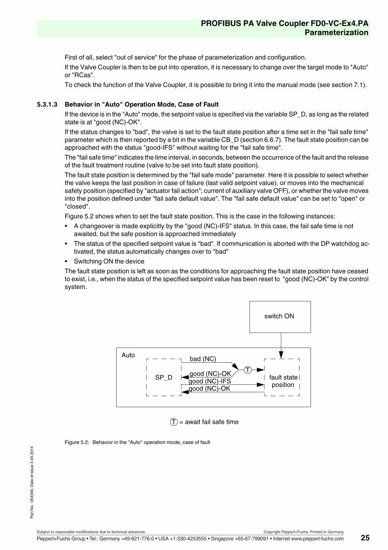
5.3.1.3 Behavior in "Auto" Operation Mode, Case of FaultIf the device is in the "Auto" mode, the setpoint value is specified via the variable SP_D, as long as the related state is at "good (NC)-OK".If the status changes to "bad", the valve is set to the fault state position after a time set in the "fail safe time" parameter which is then reported by a bit in the variable CB_D (section 6.6.7). The fault state position can be approached with the status "good-IFS" without waiting for the "fail safe time".The "fail safe time" indicates the time interval, in seconds, between the occurrence of the fault and the release of the fault treatment routine (valve to be set into fault state position).The fault state position is determined by the "fail safe mode" parameter. Here it is possible to select whether the valve keeps the last position in case of failure (last valid setpoint value), or moves into the mechanical safety position (specified by "actuator fail action"; current of auxiliary valve OFF), or whether the valve moves into the position defined under "fail safe default value". The "fail safe default value" can be set to "open" or "closed".Figure 5.2 shows when to set the fault state position. This is the case in the following instances:• A changeover is made explicitly by the "good (NC)-IFS" status. In this case, the fail safe time is not
awaited, but the safe position is approached immediately• The status of the specified setpoint value is "bad". If communication is aborted with the DP watchdog ac-
tivated, the status automatically changes over to "bad"• Switching ON the deviceThe fault state position is left as soon as the conditions for approaching the fault state position have ceased to exist, i.e., when the status of the specified setpoint value has been reset to "good (NC)-OK" by the control system.
Figure 5.2: Behavior in the "Auto" operation mode, case of fault
SP_D
bad (NC)
good (NC)-OKgood (NC)-IFS
T
T = await fail safe time
switch ON
fault state
Auto
good (NC)-OK
position
25Subject to reasonable modifications due to technical advances. Copyright Pepperl+Fuchs, Printed in Germany
Pepperl+Fuchs Group • Tel.: Germany +49-621-776-0 • USA +1-330-4253555 • Singapore +65-67-799091 • Internet www.pepperl-fuchs.com
PROFIBUS PA Valve Coupler FD0-VC-Ex4.PAParameterization
Part N
o.: 05
4340
, Date
of is
sue 4
.04.20
14
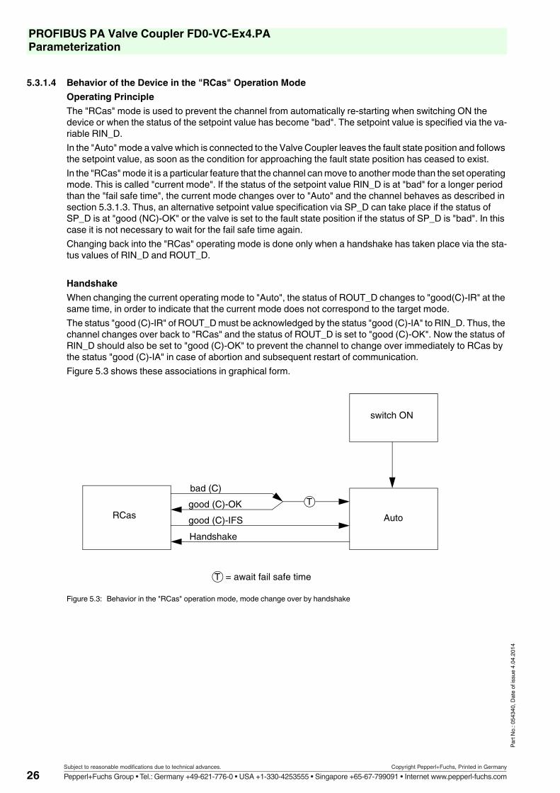
5.3.1.4 Behavior of the Device in the "RCas" Operation ModeOperating PrincipleThe "RCas" mode is used to prevent the channel from automatically re-starting when switching ON the device or when the status of the setpoint value has become "bad". The setpoint value is specified via the va-riable RIN_D.In the "Auto" mode a valve which is connected to the Valve Coupler leaves the fault state position and follows the setpoint value, as soon as the condition for approaching the fault state position has ceased to exist.In the "RCas" mode it is a particular feature that the channel can move to another mode than the set operating mode. This is called "current mode". If the status of the setpoint value RIN_D is at "bad" for a longer period than the "fail safe time", the current mode changes over to "Auto" and the channel behaves as described in section 5.3.1.3. Thus, an alternative setpoint value specification via SP_D can take place if the status of SP_D is at "good (NC)-OK" or the valve is set to the fault state position if the status of SP_D is "bad". In this case it is not necessary to wait for the fail safe time again.Changing back into the "RCas" operating mode is done only when a handshake has taken place via the sta-tus values of RIN_D and ROUT_D.
HandshakeWhen changing the current operating mode to "Auto", the status of ROUT_D changes to "good(C)-IR" at the same time, in order to indicate that the current mode does not correspond to the target mode.The status "good (C)-IR" of ROUT_D must be acknowledged by the status "good (C)-IA" to RIN_D. Thus, the channel changes over back to "RCas" and the status of ROUT_D is set to "good (C)-OK". Now the status of RIN_D should also be set to "good (C)-OK" to prevent the channel to change over immediately to RCas by the status "good (C)-IA" in case of abortion and subsequent restart of communication.Figure 5.3 shows these associations in graphical form.
Figure 5.3: Behavior in the "RCas" operation mode, mode change over by handshake
bad (C)
Handshake
good (C)-IFS
T
T = await fail safe time
switch ON
AutoRCasgood (C)-OK
26Subject to reasonable modifications due to technical advances. Copyright Pepperl+Fuchs, Printed in Germany
Pepperl+Fuchs Group • Tel.: Germany +49-621-776-0 • USA +1-330-4253555 • Singapore +65-67-799091 • Internet www.pepperl-fuchs.com

PROFIBUS PA Valve Coupler FD0-VC-Ex4.PAParameterization
Part N
o.: 05
4340
, Date
of is
sue 4
.04.20
14
5.3.2 Parameters Concerning Actuator and Final Position Feedback
5.3.2.1 Actuator Fail Action (Mechanical Safety Position)This is to identify the type of valve to be used (self-opening or self-closing) (see also section 5.3.1.1); the whole chain consisting of auxiliary valve, actuator, and final controlling element must be taken into con-sideration right here. Setting must be made according to the mechanical drive.Default setting is "closed", i.e., self-closing. This setting can be changed to "open" (self-opening). Setting of the actuator fail action indicates the status of the actuator if the current of the auxiliary valve is OFF.
5.3.2.2 Sensor ModeThis parameter indicates whether the PFCs are "low active" (default setting), "high active" or there is "No Po-sition Check". The setting must be made in correspondence with the mechanical and electrical conditions (see also section 3.2.3). Here, the PFCs must give feedbacks in the valve positions "open", "intermediate po-sition" and "closed", which correspond to one of three possible versions. "No Position Check" is equal to "high active", but if the position of the actuator is undefined the variable Readback (RB_D) is not set to "BAD".
The signals of the PFCs are coded as follows:high current logical 1low current logical 0
Example:• Mechanical switches are used as final position feedback contacts (PFCs) which have a high current flow
in actuated state (switch pressed = actuated high current, logical 1).• The valve is closed when not controlled.• If the valve is closed ("closed" position), PFC A is not actuated (0) and PFC B is actuated (1).• Both PFCs are not actuated (0) in the intermediate position.This setting is not possible as both PFCs are not actuated in the intermediate position like in version 1, in the "closed" position, however PFC A is not actuated and PFC B is actuated, i.e., exactly reversed as compared with version 1. To solve this problem, the supply cables to the PFCs must be exchanged. So the feedback of both PFCs is exchanged and PFC A is actuated (1) in the "closed" position and PFC B is not actuated (0).Now the settings have to be made as follows:• "Actuator fail action" is "closed" (determined by the valve only)• "Sensor mode" is "low active" (default setting)
For the "actuator fail action" parameter and the valve setting times (section 5.3.3.3) an initializa-tion run is provided (section 7.1.1) determining these parameters independently. "Sensor mode" , however, must always be set correctly.
Position of actuatorVersion 1low active
Version 2high active
Version 3No Position Check
PFC A PFC B PFC A PFC B PFC A PFC BOpen 0 1 1 0 1 0Close 1 0 0 1 0 1Intermediate position 0 0 1 1 1 1undefined 1 1 0 0 0 0
27Subject to reasonable modifications due to technical advances. Copyright Pepperl+Fuchs, Printed in Germany
Pepperl+Fuchs Group • Tel.: Germany +49-621-776-0 • USA +1-330-4253555 • Singapore +65-67-799091 • Internet www.pepperl-fuchs.com

PROFIBUS PA Valve Coupler FD0-VC-Ex4.PAParameterization
Part N
o.: 05
4340
, Date
of is
sue 4
.04.20
14
5.3.3 Channel Specific Parameters for Diagnosis5.3.3.1 Wire Check
The most important diagnosis parameters include wire check for lead breakage (LB) and short circuit (SC). Following monitoring modes are possible:
If the monitoring mode IO-specific is enabled, the settings can be independently made for each PFC or valve. In the case that the software version of the Valve Coupler is less than 1.5, no other settings then OFF can be made (IO-specific means OFF).
5.3.3.2 Stroke CounterThe Valve Coupler can monitor the strokes of the valve. A stroke is beginning in the valve status "open" and continues with a closing and opening procedure. The stroke counter thus increases by 1, after the valve is closed and opened again. The number of strokes can be compared with a freely adjustable limit value. A message is released if this limit value is exceeded.To activate the stroke monitoring process, either "stroke counter" or "time monitor and stroke counter" is set in the "valve monitor" parameter. For "time monitor and stroke counter" monitoring of the valve setting times is activated in addition (see section 5.3.3.3). The current counter reading is in the "stroke counter" parameter and can also be changed over to a specified value if the valve e.g., has already been in operation. The limit value is entered in the "limit stroke counter" parameter. Only when this limit value is exceeded, the message "limit stroke counter exceeded" is given (bit 16 in CB_D, see section 6.6.7).
5.3.3.3 Time MonitoringThe Valve Coupler can monitor the breakaway and transit times of the valve. In the "valve monitor" parameter either "time monitor" or "time monitor and stroke counter" is set. For "time monitor and stroke counter" the stroke counter is activated in addition (see section 5.3.3.2).A reference value and a tolerance value can be set for the breakaway and transit times. The tolerance value is used to avoid fault messages due to normal variations of the process and ambient conditions.Depending on the parameterization tool used, the unit of these time values can be different. This is why it is necessary to take into consideration the units indicated by the parameterization tool when parameterizing. If no unit is indicated, the time is set in multiples of 10 ms.The breakaway and transit times are monitored during the opening and closing process. Exceeding a time is indicated if the time measured by the Valve Coupler is longer than the reference value plus tolerance or shor-ter than the reference value minus tolerance.Blocking of the valve is indicated if the new final position is not reached after control and after the 5fold time of the breakaway time plus transit time.
Monitoring mode Sampled deviceLB + SC monitoring Valve + PFC A + PFC BLB- monitoring Valve + PFC A + PFC BSC-monitoring Valve + PFC A + PFC BIO-specific Individual user settings
SC monitoring of the auxiliary valve is possible only, for technical reasons, when the auxiliary valve is triggered. If the valve is triggered rarely but shall be checked for lead short circuit at regu-lar intervals it is possible to activate the cyclic function test (section 5.3.3.4). During this test the supply leads of the auxiliary valve are checked for short circuit.
If " No Position Check" is set for the parameter "Sensor mode", the stroke counter monitoring is not activated (see section 5.3.2.2).
28Subject to reasonable modifications due to technical advances. Copyright Pepperl+Fuchs, Printed in Germany
Pepperl+Fuchs Group • Tel.: Germany +49-621-776-0 • USA +1-330-4253555 • Singapore +65-67-799091 • Internet www.pepperl-fuchs.com

PROFIBUS PA Valve Coupler FD0-VC-Ex4.PAParameterization
Part N
o.: 05
4340
, Date
of is
sue 4
.04.20
14
The indications are given via the variable CB_D (see section 6.6.7).
For the definition of the breakaway and transit times refer to figure 5.4. The feedbacks of the PFCs are given both for the setting "low active " and "high active" of the "Sensor mode".
Figure 5.4: Definition of breakaway and transit times
IThe tolerance of the time monitoring is 40 ms. If this function should be used for very fast valves us e.g., an air choker valve to so it down.
If " No Position Check" is set for the parameter "Sensor mode", the time monitoring is not activa-ted (see section 5.3.2.2).
Open
Closed
1
0
1
0
Time
Time
Time
Valve position
PFC A
PFC B
1 = breakaway time closed->open2 = transit time closed->open3 = breakaway time open->closed4 = transit time open->closed
Open
Closed
Time
Setpoint of valve
1 2 3 4
Feedback
Intermediate position {0
1
0
1
Ver
sion
2
Ver
sion
1
29Subject to reasonable modifications due to technical advances. Copyright Pepperl+Fuchs, Printed in Germany
Pepperl+Fuchs Group • Tel.: Germany +49-621-776-0 • USA +1-330-4253555 • Singapore +65-67-799091 • Internet www.pepperl-fuchs.com

PROFIBUS PA Valve Coupler FD0-VC-Ex4.PAParameterization
Part N
o.: 05
4340
, Date
of is
sue 4
.04.20
14
5.3.3.4 Cyclic Function TestA cyclic function test can be activated for each channel. This is appropriate e.g., if a valve is controlled rarely but shall be monitored for correct functioning at regular intervals. To do so, the "cyclic function test" para-meter must be set to "ON" (factory setting is "OFF") and in the "period of cyclic function test" parameter the intervals are specified in which the test shall be carried out (see "sequence"). Depending on the tool used, the unit of the time to be set can be different. Thus, it is necessary to take into consideration the unit specified by the parameterization tool when parameterizing. If no unit is specified, time adjustment is done in seconds.
SequenceAfter the set time elapsed, the valve is controlled – for a short period of time – into the position opposite to the current position until breakaway of the valve is indicated by the relevant final position sensor. Thereupon the valve is controlled back immediately, i.e., a running process does not suffer interference from the test. This procedure is repeated periodically.Monitoring of the valve times is active during the tests. The indication that the breakaway time, measured du-ring the test, is exceeded or fallen below is given via the variable CB_D (see section 6.6.7). It also detects and indicates that the valve is blocked.
5.3.4 Setting the Documentation ParametersThe data "manufacturer", "product type" and "serial number" can be stored for the actuator and the actuating drive. "Parameter revision control drive" indicates the number of changing the parameters of the actuator and the actuating drive. The parameter itself cannot be modified.In addition, "Identification" can be used to store information about the batch process (recipe) and the operating unit (measuring point). "Parameter revision output" indicates the number of changing the para-meters of the output and identification. The parameter itself cannot be modified.
If " No Position Check" is set for the parameter "Sensor mode", the cyclic function test is not acti-vated (see section 5.3.2.2).
30Subject to reasonable modifications due to technical advances. Copyright Pepperl+Fuchs, Printed in Germany
Pepperl+Fuchs Group • Tel.: Germany +49-621-776-0 • USA +1-330-4253555 • Singapore +65-67-799091 • Internet www.pepperl-fuchs.com

PROFIBUS PA Valve Coupler FD0-VC-Ex4.PAParameterization
Part N
o.: 05
4340
, Date
of is
sue 4
.04.20
14
5.4 Write ProtectionThe write protection is used to protect the parameters from modification. All acyclic write accesses are blocked. Also the write accesses to user data are blocked if these are transferred in an acyclic manner (e.g., some tools offer the opportunity to read and write user data in an acyclic manner).There are two possibilities to activate the write protection:• Activation via the DIP switch 8. This is the "Hardware write protection" (see figure 5.5)• Activation via the "Software write protection" parameterThe effects are the same, however, it is possible – in the case of the software write protection – to overwrite the "write protection" parameter so that the write protection can be deactivated, too.
Figure 5.5: Setting the hardware write protection
The "Software write protection" parameter is set in general via a specific software function. Representation and operation of this parameter thus depends on the parameterization tool used.
Hardware write protection
PROFIBUS address
ON: activeOFF: not active
(default setting)
8
20212223242526
ON
OF
F
1
2 3 4
5 6
7
31Subject to reasonable modifications due to technical advances. Copyright Pepperl+Fuchs, Printed in Germany
Pepperl+Fuchs Group • Tel.: Germany +49-621-776-0 • USA +1-330-4253555 • Singapore +65-67-799091 • Internet www.pepperl-fuchs.com

PROFIBUS PA Valve Coupler FD0-VC-Ex4.PAConfiguration
Part N
o.: 05
4340
, Date
of is
sue 4
.04.20
14
6 Configuration6.1 General
This chapter describes how to set up the cyclic communication and the structure of user data with status. The checklist of section 4.3 is continued.
6.2 Log in Valve Coupler at DP MasterBefore communication is possible with a PROFIBUS field device, it must be designed in the PROFIBUS mas-ter.In section 5.2.2 design has been prepared by specifying the GSD file to be used by selecting the PROFIBUS Ident Number.Now a new slave must be created in the DP slave configuration in the design tool. If the manufacturer specific Ident Number was selected, now select the Valve Coupler FDO-VC-Ex4.PA from the device catalog of the design tool and add this to the list of new slaves. If the profile specific Ident Number was selected, select a 4-channel digital output (4 DO). For details on these procedures, please refer to the documentation of the design tool.
6.3 Installation of GSD FileIf the manufacturer specific Ident Number was selected and the Valve Coupler is not included as a slave in the device catalog of the design tool, the catalog can be updated by installing the GSD file which is provided on the enclosed data carrier. The GSD file is also available at the Pepperl+Fuchs homepage www.pepperl-fuchs.com.The profile-specific GSD file is available via the homepage of PNO (www.profibus.com).How to import the GSD file in the design tool is described in the operating instructions.
6.4 Select Module IdentifiersIf the Valve Coupler was designed in the PROFIBUS master, it is possible to select "module identifiers". This selection establishes whether and with what characteristics a channel is used. To do so, select for each of the four channels a text description (identifier) of the data to be exchanged with the field device from the GSD file of the field device, or, if necessary, enter the identifier bytes directly. The identifier bytes are given in plain language in the GSD file.
Different module identifiers can be selected for the four channels. The module identifier defines which user data are transferred in the cyclic data exchange.
Generally, the manufacturers of design tools include all available devices in the device catalog of the design tool. If the Valve Coupler is not included in the catalog, the necessary GSD file can be installed as described in section 6.3. Furthermore, it is possible to implement the catalog via the manufacturer of the design tool.
The modules of a PROFIBUS PA slave are so-called virtual slots. Depending on the manufactu-rer and software, different terms are used.The terms module, slot and channel are partially used as synonyms.
If not all four channels of the Valve Coupler are to be operated, the free channels between used channels must be assigned the empty module identifier. No identifiers need to be assigned to unused channels that follow the last used channel.
32Subject to reasonable modifications due to technical advances. Copyright Pepperl+Fuchs, Printed in Germany
Pepperl+Fuchs Group • Tel.: Germany +49-621-776-0 • USA +1-330-4253555 • Singapore +65-67-799091 • Internet www.pepperl-fuchs.com

PROFIBUS PA Valve Coupler FD0-VC-Ex4.PAConfiguration
Part N
o.: 05
4340
, Date
of is
sue 4
.04.20
14
The module identifiers consist of a combination of possible user data variables. To be able to represent the available module identifiers in a clear form, the individual user data variables are explained at first.The variables may be input or output data. Output data are data which are transmitted from the control system to the process (device). Input data are transmitted from the process (device) to the control system.The following user data variables can be used:• SP_D: Specified setpoint value of valve position in the "Auto" mode. User data length 2 bytes output data.• RB_D: Feedback of valve position and the states of the PFCs and their lead faults. User data length 2
bytes input data.• CB_D: Detailed status, alarm, and fault signals of the valve. User data length 3 bytes input data.• RIN_D: Specified setpoint value of host in the "RCas" operating mode. User data length 2 bytes output
data.• ROUT_D: Setpoint value feedback to host in the "RCas" operating mode. User data length 2 bytes input
data.
The following table gives all possible module identifiers (the combinations offered by the device) with the user data lengths which are transferred in the cyclic data exchange:
The contents and codes are described in section 6.6.
IdentifierUser data length
NoteOutput data
Input data
EMPTY_MODULE 0 0 Empty moduleSP_D 2 0 Specified setpoint valueSP_D+RB_D 2 2 Setpoint value + feedback PFCSP_D+CB_D 2 3 Setpoint value + diagnosisSP_D+RB_D+CB_D 2 5 Setpoint value + feedback PFC + diagnosisRIN_D+ROUT_D 2 2 Setpoint value hostRIN_D+ROUT_D+CB_D 2 5 Setpoint value host + diagnosisSP_D+RB_D+RIN_D+ROUT_D+CB_D 4 7 Setpoint value host + feedback PFC + diag-
nosis
The most frequently used module identifiers are SP_D+RB_D as well as SP_D+RB_D+CB_D. The channel is operated in the "Auto" mode. The "RCas" mode is used to implement a certain behavior in case of failure.The modes of operation and their use is described in section 5.3.1.2.
33Subject to reasonable modifications due to technical advances. Copyright Pepperl+Fuchs, Printed in Germany
Pepperl+Fuchs Group • Tel.: Germany +49-621-776-0 • USA +1-330-4253555 • Singapore +65-67-799091 • Internet www.pepperl-fuchs.com

PROFIBUS PA Valve Coupler FD0-VC-Ex4.PAConfiguration
Part N
o.: 05
4340
, Date
of is
sue 4
.04.20
14
6.5 Example of ConfigurationThe second and third out of four possible valves are assigned. Lead monitoring is to be carried out for both valves (CB_D). For the third valve, an additional final position feedback and monitoring is to be made (RB_D). The operating mode for the second valve is "Auto", for the third "RCas". The list of the modules used should then have the following structure:
The user data transferred to the device (output data) have a length of 0 + 2 + 4 + 0 = 6 bytes.The user data transferred from the device (input data) have a length of 0 + 3 + 7 + 0 = 10 bytes.
6.6 Description of User Data6.6.1 General
The available variables have been described in section 6.4. These variables are explained in more detail in this section.The variables SP_D, RB_D, RIN_D and ROUT_D consist of two bytes each. The first byte includes the setpoint value or the setpoint value feedback for valve control, the second byte contains the associated status. SP_D and RIN_D are output data (data to the device), RB_D and ROUT_D are input data (data from device).
6.6.2 Arrangement of the Status of SP_D, RB_D, RIN_D and ROUT_DCorrect setting (output data) and evaluation (input data) of the status is very important as here the fault is re-ported, commands are given and the change over of operating modes is controlled. The status byte consists of 2 quality bits (bits 6 and 7), the sub-status (bits 2 ... 5) and 2 limit value bits (bits 0 and 1).Initially, the quality bits define the quality of the data value roughly in the first byte; the sub-status gives detailed information of the quality.Here, only the two quality bits are explained for orientation; details will follow for the individual user data.
Pos. Module Use1 EMPTY_MODULE Valve 1: Empty module as the valve is not used2 SP_D+CB_D Valve 2: Specified setpoint value of valve with fault
feedback in "Auto" mode
3
SP_D+RB_D+RIN_D+ROUT_D+CB_D Valve 3: Specified setpoint value of valve with fault feedback and final position monitoring (likewise with fault feedback) in "RCas" mode. The identifier must contain the variable "RB_D" for the final position feed-back.
4 EMPTY_MODULE or no specification Valve 4: Empty module or no assignment as the valve is not used and no used channels follow.
Bit no.MeaningQuality Sub-status Limit
value7 6 5 4 3 2 1 00 0 bad0 1 uncertain1 0 good (NC) (Not Cascade)1 1 good (C) (Cascade)
34Subject to reasonable modifications due to technical advances. Copyright Pepperl+Fuchs, Printed in Germany
Pepperl+Fuchs Group • Tel.: Germany +49-621-776-0 • USA +1-330-4253555 • Singapore +65-67-799091 • Internet www.pepperl-fuchs.com

PROFIBUS PA Valve Coupler FD0-VC-Ex4.PAConfiguration
Part N
o.: 05
4340
, Date
of is
sue 4
.04.20
14
6.6.3 Variable SP_DThis variable includes the specified setpoint value of the valve position in the "Auto" mode of operation. The setpoint value controls the set position of the whole actuating drive. The setpoint value is a number from 0 to 255 (1 byte). The set position can be "closed" or "open".
Such a specified setpoint value is contradictory to many conventional devices at which, e.g., the number "0" is coded by "valve current OFF" and "1" by "valve current ON". Thus, the device has to know whether the current for the auxiliary valve must be ON or OFF in the "open" position. This is defined by the "actuator fail action" parameter (see section 5.3.2.1). It indicates the status of the actuator when the current of the auxiliary valve is OFF.Which number(s) correspond(s) to which set position depends on the setting of the "invert setpoint" parame-ter. If this parameter is at "OFF", the setpoint value is not inverted and the setpoint value "0" controls the drive into the "closed" position, setpoint value "unequal to 0" (i.e. 1 ... 255) into position "open".However, if this parameter is at "ON", the coding of the setpoint value is inverted, i.e., the setpoint value "0" controls the drive into the "open" position, setpoint values "unequal to 0" (i.e., 1 ... 255) into the "closed" po-sition.
Three examples:1. Setpoint inversion is OFF. The actuator moves into the closed position ("closed"), if the current of the
auxiliary valve is OFF.If the setpoint value is "0" ("closed"), the auxiliary valve is not triggered. In this case "0" corresponds to "current OFF".
2. Setpoint inversion is OFF. The actuator moves in the open position ("open"), if the current of the auxiliary valve is OFF.If the setpoint value is "0" ("closed"), the auxiliary valve is triggered. In this case "0" corresponds to "cur-rent ON".
3. Setpoint inversion is ON. The actuator moves in the closed position ("closed"), if the current of the auxiliary valve is OFF.If the setpoint value is "0" ("open"), the auxiliary valve is triggered. In this case "0" corresponds to "current ON".
The status of SP_D makes a difference – except "good-IFS" – according to the quality only. There is no other differentiation. The relevant status values are:
If the setpoint value shall be taken over by the Valve Coupler, it is necessary to transfer the value "good" (NC)-OK" (80h) in the status (second byte)!
Binary value
Hex value Meaning
10100000 A0h "good (NC)-IFS" (initiate fail-safe); command for channel to move to the fault state10000000 80h "good (NC)-OK"; valid setpoint value; which should be used as the standard value
for "good".11............10............01............
40h"uncertain", "good (C)", "good (NC)";valid setpoint value; all values 40h ... BFh except A0h;The value 80h should be used preferably.
00............ 3Fh "bad"; all values 00h ... 3Fh.
35Subject to reasonable modifications due to technical advances. Copyright Pepperl+Fuchs, Printed in Germany
Pepperl+Fuchs Group • Tel.: Germany +49-621-776-0 • USA +1-330-4253555 • Singapore +65-67-799091 • Internet www.pepperl-fuchs.com

PROFIBUS PA Valve Coupler FD0-VC-Ex4.PAConfiguration
Part N
o.: 05
4340
, Date
of is
sue 4
.04.20
14
6.6.4 Variable RIN_DThis variable contains the specified setpoint value of the valve position in the "RCas" mode (see section 5.3.1.4). Coding is analogue to SP_D (see section 6.6.3), i. e. if RIN_D is 0 with the inversion switched OFF, the valve is closed, the valve is opened at all other values (1 ... 255); if RIN_D is 0 with the inversion switched ON, the valve is opened, the valve is closed at all other values (1 ... 255). The relevant status values are:
6.6.5 Variable RB_DRB_D gives the feedback of the valve position and the states of the PFCs and their lead faults. Coding of in-formation is given in the following table:
The following table shows the status messages relevant to RB_D. Here, the limit value bits in the "bad - sensor failure" error condition are used, also.
Binary value
Hex value Meaning
11000000 C0h "good (C)-OK"; valid setpoint value11000001 C1h "good (C)-IA" (initialization acknowledge); clearance from control system to
change to the "RCas" mode11100000 E0h "good (C)-IFS" (initiate fail-safe); command for channel to change to the "Auto"
mode10............01............00............
C0h"good (NC)", "uncertain", "bad";invalid setpoint value; change to "Auto" mode
If the setpoint value shall be taken over by the Valve Coupler the value "good (C) - OK" (C0h) must be transferred after the handshake described in section 5.3.1.4 in the status (second byte)!
Bit Meaning of feedback0+1 Valve position 0 = unknown, 1 = closed, 2 = open, 3 = intermediate position
2 Proximity sensor A
0 = actuated, 1 = not actuated3 0 = no lead short circuit, 1 = lead short circuit4 0 = no lead interruption, 1 = lead interruption5 Proximity sensor
B0 = actuated, 1 = not actuated
6 0 = no lead short circuit, 1 = lead short circuit7 0 = no lead interruption, 1 = lead interruption
Binary value
Hex value Meaning
10000000 80h "good (NC)-OK"; feedback value valid10000100 84h "good (NC)-UE" (update event); 10 second message for parameter changes00001100 0Ch "bad (NC)-DF" (device failure); electric hardware fault. Send the device to
Pepperl+Fuchs for repair.00010000 10h "bad (NC)-SF", sensor combination not allowed (section 8.5)00010001 11h "bad (NC)-SF", lead short circuit00010010 12h "bad (NC)-SF", lead interruption
The failure states ("bad") have a higher priority than the "good" states, so that, e.g., the "Update Event" is no longer transferred to the control system in case of a lead fault!
36Subject to reasonable modifications due to technical advances. Copyright Pepperl+Fuchs, Printed in Germany
Pepperl+Fuchs Group • Tel.: Germany +49-621-776-0 • USA +1-330-4253555 • Singapore +65-67-799091 • Internet www.pepperl-fuchs.com

PROFIBUS PA Valve Coupler FD0-VC-Ex4.PAConfiguration
Part N
o.: 05
4340
, Date
of is
sue 4
.04.20
14
6.6.6 Variable ROUT_DThis variable provides the setpoint value of the valve which is re-transferred by RIN_D for monitoring. It does not include information of the states of the PFCs. The status is used chiefly to control the sequence of module change in case of failure (see section 5.3.1.4).Relevant status values:
6.6.7 Variable CB_DThe variable CB_D provides detailed status, alarm and fault signals of the valve which are coded in bits. It consists of 3 bytes (24 bits):
Binary value
Hex value Meaning
11000000 C0h "good (C)-OK"; valid setpoint value11000010 C2h "good (C)-IR" (initialization request); clearance request by slave to master to
change to the "RCas" mode.11001100 CCh "good (C)-NI" (not invited); "RCas" is not set as the target mode.00001100 0Ch "bad-DF" (device failure); electric hardware fault. Send device to Pepperl+Fuchs
for repair.00011100 1Ch "bad-OS" (out of service); is set in the "O/S" mode
Bit Meaning Reference0 The valve is set to fault state Section 5.3.1.31 unused2 unused3 unused4 After a correct switching operation, the valve has left the appropriate end position
or the PFCs show an invalid position.Section 8.7
5 Lead breakage of valve Section 5.3.3.16 Lead short circuit of valve Section 5.3.3.17 unused8 Valve is just opening9 Valve is just closing
10 Update-Event; 10 second message when changing the parameters of this channel Section 6.6.511 The channel is in simulation mode Section 7.212 unused13 unused
14Valve moved into the mechanical safety position• in case of fault, if fault state = "actuator fail action"• in "Man" mode, if status of manual setpoint of valve is at "bad"
Section 5.3.2.1
15 A cyclic functional test is currently carried out Section 5.3.3.416 The limit value for the stroke counter has been exceeded Section 5.3.3.217 The breakaway time OPEN-CLOSED incl. tolerance has been exceeded/fallen
belowSection 5.3.3.3
18 The breakaway time CLOSED-OPEN incl. tolerance has been exceeded/fallen below
Section 5.3.3.3
19 A fault occurred during the cyclic function test of the valve Section 8.720 The transit time OPEN-CLOSED incl. tolerance has been exceeded/fallen below Section 5.3.3.321 The transit time CLOSED-OPEN incl. tolerance has been exceeded/fallen below Section 5.3.3.322 Actuating drive or valve mechanically blocked Section 5.3.3.323 unused
37Subject to reasonable modifications due to technical advances. Copyright Pepperl+Fuchs, Printed in Germany
Pepperl+Fuchs Group • Tel.: Germany +49-621-776-0 • USA +1-330-4253555 • Singapore +65-67-799091 • Internet www.pepperl-fuchs.com

PROFIBUS PA Valve Coupler FD0-VC-Ex4.PAConfiguration
Part N
o.: 05
4340
, Date
of is
sue 4
.04.20
14
6.7 Description of Slave DiagnosisIf a fault occurs in the device or at a channel, the slave diagnosis is automatically transferred event-controlled. The exact cause can then be looked for using a parameterization tool.The slave diagnosis consists of 14 bytes and is structured as follows:
Byte no. Bit Value Meaning1 ... 6 Standard diagnosis acc. to PROFIBUS standard7 08h The bytes 7 ... 10 are provided for future extensions. The bytes 7 ... 9 for the
Valve Coupler are assigned with fixed values.Byte 10 specifies the content of the bytes 11 ... 14 in a more detailed way.
8 FEh9 00h10 01h a fault appears
02h a fault disappears03h a fault appears and a fault disappears
11 0 Electrical hardware failure. Please return device to Pepperl+Fuchs for repair.1 Actuator blocked2 ... 3 unused4 Checksum error EEPROM. Please return device to Pepperl+Fuchs for repair.5 ... 6 unused7 unused
12 0 ... 4 unused5 Limit value of stroke counter exceeded, breakaway or transit time outside of
limits6 unused7 During an existing cyclic connection the PROFIBUS Ident Number was parame-
terized with a different value.Consequence: After the next clearance time, e.g., triggered by a short-term voltage failure, no connection to the master can be re-established, as this was configured with a different Ident Number.
13 ... 14 unused
Bits of the diagnosis remain set as long as the cause for the message exists.If one of the bits of diagnosis is set, Bit 12 is set in the variable CB_D of all channels as a sign that a new diagnosis information is provided.
38Subject to reasonable modifications due to technical advances. Copyright Pepperl+Fuchs, Printed in Germany
Pepperl+Fuchs Group • Tel.: Germany +49-621-776-0 • USA +1-330-4253555 • Singapore +65-67-799091 • Internet www.pepperl-fuchs.com

39
PROFIBUS PA Valve Coupler FD0-VC-Ex4.PAOperation
Subject to reasonable modifications due to technical advances. Copyright Pepperl+Fuchs, Printed in Germany
Pepperl+Fuchs Group • Tel.: Germany +49-621-776-0 • USA +1-330-4253555 • Singapore +65-67-799091 • Internet www.pepperl-fuchs.com
Part N
o.: 05
4340
, Date
of is
sue 4
.04.20
14
7 Operation7.1 Manual Operating Mode
In this mode of operation it is possible to manually control a channel by acyclic data exchange, e.g., using a separate parameterization tool, and maintenance and servicing functions can be executed.When selecting the "Man" mode, the last status of the "Auto" or "RCas" mode is frozen.
7.1.1 Initialization RunThe "actuator fail action" (mechanical safety position) and the reference values for the breakaway and transit times and their tolerances can be taught in automatically by an "initialization run". The initialization run must be carried out individually for each channel. Whether and how the initialization run can be started depends on the parameterization tool used.
7.1.2 Sequence
To ensure that the valve is in the "mechanical safety position" it is checked whether the valve current is off and the valve is in a final position. If this is not the case, the valve current is turned off and waited at least 10 seconds until the valve reaches a final position.Starting at the current valve position, the opposite final position is controlled and the breakaway and transit time is measured. As soon as the final position is reached, the valve remains in this position (at least 4 se-conds) for a fifth of the transit time measured and returns than into the initial position. The breakaway and transit time is also measured here.The measured times are taken over in the parameterization of the relevant channel as reference value para-meters for the breakaway and transit times. 30% of the measured times are entered as tolerance values.
Based on the feedbacks of the PFCs the effective direction of the valve is detected and stored in the device.
7.1.3 Direct Setpoint Value SpecificationIn the "Man" mode it is possible to specify a valve position with status bypassing the control system. The val-ve responds directly on this specified setpoint value without taking into account other parameters, e.g., "in-vert setpoint").This type of setpoint value specification is used primarily for test purposes to check the valve or the Valve Coupler for proper functioning.
7.2 SimulationSimulation is available in any mode of operation. If activated, it is possible to specify the variable RB_D manually, both of the data value and the status. Simulation is primarily used to check the implementation of the control system by simulating line faults (LB/SC) at the device or faulty set positions.
Set the correct mechanical safety position of the connected valve, before you start the initializa-tion run.
During initialization run the valve time parameters are write-protected in order to exclude access conflicts.

PROFIBUS PA Valve Coupler FD0-VC-Ex4.PADiagnosis and Error Correction
Part N
o.: 05
4340
, Date
of is
sue 4
.04.20
14
8 Diagnosis and Error Correction8.1 General
This chapter gives hints on how to behave in case of faults and describes possible causes of fault.
8.2 LEDsThe Valve Coupler is provided with 6 LEDs at the front side of the device which inform of the status of the device and of faults related to the hardware which must be eliminated in situ in general.
Bild 8.1: LEDs on the device
1 Note: The light intensity is low for reasons of power saving.
Faults and failures are reported by the Valve Coupler via the following (data) objects:• Light emitting diodes (see section 8.2)• Variable "RB_D" and its status (see section 6.6.5)• Variable "ROUT_D" and its status (see section 6.6.6)• Variable "CB_D" (see section 6.6.7)• Slave-diagnosis (see section 6.7)
LED States DescriptionPWR CHK1 OFF No power supply
Permanently green Power supply available, device is ready to operateCOM/ERR OFF Cyclic communication established to a class 1 master
Red (flashing) • Device was not configured with a class 1 master• Timeout in the cyclic communication
Permanently red Fault in device hardware, e.g., writing/reading error in EEPROM or valve voltage not available
IN/OUT CHK:(channel 1...4)
OFF No faults detectedRed (flashing) • Lead breakage or short circuit of valve and/or of one PFC (only with
activated line testing and operating modes unequal to O/S)• Fault in cyclic function test (only if this option had been activated)
The LEDs "IN/OUT CHK" of the four channels indicate only fault states of the valves or final posi-tion feedback contacts, not the valve control!
channel 1 channel 2 channel 3 channel 4
40Subject to reasonable modifications due to technical advances. Copyright Pepperl+Fuchs, Printed in Germany
Pepperl+Fuchs Group • Tel.: Germany +49-621-776-0 • USA +1-330-4253555 • Singapore +65-67-799091 • Internet www.pepperl-fuchs.com

PROFIBUS PA Valve Coupler FD0-VC-Ex4.PADiagnosis and Error Correction
Part N
o.: 05
4340
, Date
of is
sue 4
.04.20
14
8.3 Functional Check without Connected ValvesThe valve control outputs of the Valve Coupler can also be checked for correct functioning without connected valves by simulating the valve by a 3 k resistor.
The voltage drop above the resistor, measured by means of a multimeter, indicates whether the output current for the auxiliary valve is ON or OFF:
The operating mode "Man" is used to manually control the channel, see section 7.1.3.
Voltage above the 3 k resistance Status of outputapprox. 0.3 VDC current switched offapprox. 3 VDC current switched on
The status of the output cannot be determined by simply measuring the voltage at the open terminal of a valve output.In this case, always a voltage of 6.8...7.4 VDC is measured!
3kV+
-
41Subject to reasonable modifications due to technical advances. Copyright Pepperl+Fuchs, Printed in Germany
Pepperl+Fuchs Group • Tel.: Germany +49-621-776-0 • USA +1-330-4253555 • Singapore +65-67-799091 • Internet www.pepperl-fuchs.com

PROFIBUS PA Valve Coupler FD0-VC-Ex4.PADiagnosis and Error Correction
Part N
o.: 05
4340
, Date
of is
sue 4
.04.20
14
8.4 Possible Faults during the Initialization Run (section 7.1.1)
8.5 Status information from RB_D
Fault signal Cause Eliminationprior to start: Valve is justly set • Re-start the initialization run after the valve has
reached the set positionLead breakage or short circuit at PFCs or the auxiliary valve
• Check wiring of sensors and auxiliary valve
Valve is in wrong position • Check PFCs for connection and proper functioning
• Check parameterization of "sensor mode"• Check parameterization of "actuator fail action"• Check auxiliary power• Check mechanical drive
when carrying out the tests:
The PFCs indicated an unexpected valve position; open-intermediate-closed or vice versa is expected
• Check PFCs for connection and proper functioning
Breakaway time is larger than 1 min • Mechanical drive or auxiliary valve defective• Check PFCs for connection and proper
functioningTransit time larger than 3 min • Mechanical drive or auxiliary valve defective
• Check PFCs for connection and proper functioning
The line test revealed a fault • Check LEDs and diagnosis messages• Check wiring of PFCs and valve
Status information Cause Elimination Cross
referenceBad-O/S Channel is in mode "O/S" (out of
service).Set target mode "Auto", "RCas" or "Man".
Section 5.3.1.2
Bad-DF A hardware fault was recognised. In addition, the LED "COM/ERR" lights permanently. A hardware fault is indicated in the slave dia-gnosis.
Please return device to Pepperl+Fuchs for repair.
Section 6.6.5Section 6.7
Bad-SF Lead interruption of sensor Determine the affected sensor via the variable RB_D.
Section 6.6.5
Bad-SF Lead short circuit of sensor Determine the affected sensor via the variable RB_D.
Section 6.6.5
Bad-SF "Not allowed sensor combina-tion":The feedback of the PFCs is not assigned to a valve position.
• Check parameterization of "sensor mode".
• Check PFCs for proper functioning.
Section 5.3.2.2
Good (NC)-UE Parameters have been modified. After 10 s this event information is reset automatically.
Section 6.6.5
42Subject to reasonable modifications due to technical advances. Copyright Pepperl+Fuchs, Printed in Germany
Pepperl+Fuchs Group • Tel.: Germany +49-621-776-0 • USA +1-330-4253555 • Singapore +65-67-799091 • Internet www.pepperl-fuchs.com

PROFIBUS PA Valve Coupler FD0-VC-Ex4.PADiagnosis and Error Correction
Part N
o.: 05
4340
, Date
of is
sue 4
.04.20
14
8.6 Status informations from ROUT_D
8.7 Variable CB_D
Status information Cause Elimination Cross
referenceBad-O/S Channel is in mode "O/S" (out
of service).Set target mode "Auto", "RCas" or "MAN".
Section 5.3.1.2
Bad-DF A hardware fault was recogni-zed. In addition, the LED "COM/ERR" lights permanently. A hardware fault is indicated in the slave diagnosis.
Please return device to Pepperl+Fuchs for repair.
Section 6.6.5Section 6.7
Good (C)-IR Channel changed over to mode "Auto".
Eliminate that fault due to which the status of RIN_D was set to "bad" by the control system; then acknowledge with the status "good (C)-IA".
Section 5.3.1.4
Good (C)-NI ROUT_D has been used, despite "RCas" was not set as the target mode
Set target mode "RCas". Section 6.6.6
Bit Signalling Cause Elimination0 The valve is set to fault state The status of SP_D or RIN_D
is at "bad" or at "good-IFS"Eliminate that fault due to which the status was set to "bad" or "good-IFS" by the control system; then set the status again to "good"
4 After a correct switching operation, the valve has left the appropriate end position or the PFCs show an invalid position.
• Auxiliary power (compres-sed air, etc.) dropped
• Mechanical drive defective• PFC defective
• Check auxiliary power• Check mechanical drive
and auxiliary valve• Check PFCs for connection
and proper functioning5 Lead breakage of valve Check supply lines to auxi-
liary valve6 Lead short circuit of valve Check supply lines to auxi-
liary valve
10Update-Event; 10 second message when changing the parameters of this channel
Parameters have been modi-fied
After 10 s this event informa-tion is reset automatically
11 The channel is in simulation mode Simulation has been switched ON
Switch OFF simulation(section 7.2)
14
Valve moved into the mechanical safety position
• The status of SP_D or RIN_D is at "bad" or "good-IFS" and "mech. safety position" is set as the fault state
• The status of the manual set-point value in "Man" mode is at "bad"
• Target mode is "O/S" (out of service)
• Eliminate that fault due to which the status had been set to "bad" or "good-IFS" by the control system, then set status again to "good".
• Set target mode "Auto", "RCas" or "MAN"
16The limit value for the stroke counter has been exceeded
• Maintain valve• Increase limit value• Deactivate stroke counter
43Subject to reasonable modifications due to technical advances. Copyright Pepperl+Fuchs, Printed in Germany
Pepperl+Fuchs Group • Tel.: Germany +49-621-776-0 • USA +1-330-4253555 • Singapore +65-67-799091 • Internet www.pepperl-fuchs.com

PROFIBUS PA Valve Coupler FD0-VC-Ex4.PADiagnosis and Error Correction
Part N
o.: 05
4340
, Date
of is
sue 4
.04.20
14
1718
The breakaway time incl. tolerance has been exceeded/fallen below
The deviation to the set time was larger than the admissible tolerance.
• Mechanical drive or auxiliary valve defective
• Check auxiliary power• Check PFCs for connection
and proper functioning
19
A fault occurred during the cyclic function test of the valve
• Line test detected a fault.• Monitoring of the valve
times is deactivated.• The PFCs do not indicate
the final position which corresponds to the current control.
• Check PFCs and valve for connection and proper functioning
• Activate time monitoring
2021
The running time incl. tolerance has been exceeded/fallen below
The deviation to the set time was larger than the admissible tolerance.
• Mechanical drive or auxiliary valve defective
• Check auxiliary power• Check PFCs for connection
and proper functioning
22
Actuating drive or valve mechani-cally blocked
The valve is indicated as blok-ked when a time of t > 5*(breakaway time + transit time) elapsed since the output of the new setpoint value.
• Mechanical drive or auxiliary valve defective
• Check auxiliary power• Check PFCs for connection
and proper functioning
Bit Signalling Cause Elimination
44Subject to reasonable modifications due to technical advances. Copyright Pepperl+Fuchs, Printed in Germany
Pepperl+Fuchs Group • Tel.: Germany +49-621-776-0 • USA +1-330-4253555 • Singapore +65-67-799091 • Internet www.pepperl-fuchs.com

PROFIBUS PA Valve Coupler FD0-VC-Ex4.PADiagnosis and Error Correction
Part N
o.: 05
4340
, Date
of is
sue 4
.04.20
14
8.8 Slave diagnosisByte.Bit Cause Elimination11.0 Electrical hardware failure. Please return device to Pepperl+Fuchs for repair.11.1 Actuator blocked. Call CB_D of the channels to find out the exact fault
cause. See section 8.7. Channel diagnosis can also be called via the parameterization tool.
11.4 Checksum error EEPROM. Please return device to Pepperl+Fuchs for repair.12.5 Limit value of stroke counter exceeded,
breakaway or transit time outside of limits
Call CB_D of the channels to find out the exact fault cause. See section 8.7. Channel diagnosis can also be called via the parameterization tool.
12.7 During an existing cyclic connection with a class 1 master the PROFIBUS Ident Number was parameterized with another value.
• Change Ident Number to the configured value.• Re-configure class 1 master, because after the
next clearance time, e.g., triggered by a short-term voltage failure, no connection to the master can be re-established as this was configured with a diffe-rent Ident Number.
45Subject to reasonable modifications due to technical advances. Copyright Pepperl+Fuchs, Printed in Germany
Pepperl+Fuchs Group • Tel.: Germany +49-621-776-0 • USA +1-330-4253555 • Singapore +65-67-799091 • Internet www.pepperl-fuchs.com

PROFIBUS PA Valve Coupler FD0-VC-Ex4.PAAppendix
Part N
o.: 05
4340
, Date
of is
sue 4
.04.20
14
9 Appendix9.1 Parameter Reference List9.1.1 Legend
: characterizes a function parameter. Functional decisive parameters which are required for operation and which must be set correctly so that the valves and/or PFCs can be operated properly.
: characterizes a diagnosis parameter. These parameters control additional device and diagnosis func-tions which have no influence on the basic functions of the valves. In addition, they provide important feedbacks for fault diagnosis and prevention. Also, this information is required for inquiries with Pepperl+Fuchs.
: characterizes a documentation parameter. These are parameters which are used for the documenta-tion and description of the device and the measuring points. They have no effect on the device func-tions.
M: Parameter can be modified (written).Because all parameters can be read, no identification is used.
9.1.2 Device-Related Parameters
Depending on the parameterization tool used, the settings of some parameters are made either in plain text or according to a certain code. Coding is described under the relevant parameters.
Charac-teristics
Parameter,Description
Range of values(bold = default settings)
Parameter revision deviceThis parameter is a counter which is incremented by 1 during each modification of a device related parameter and which documents the status of modification of parameterization in this way.
0 ... 65535
M TAG The Valve Coupler can be assigned a unique tag within the plant or process via this parameter.
(32 characters)
M Description An additional description of the measuring point can be entered within the plant or process via this parameter.
(32 characters)
M Strategy A user specific code value for the classification and summary of information, e.g. for diagnosis reports, can be assigned via this parameter.
0 ... 65535
M Message An additional description of the Valve Coupler can be entered within the plant or process via this parameter.
(32 characters)
M Alert key A user specific code value for the classification and summary of alarm messages and events, e.g., for quick localization, can be assigned via this parameter.
0 ... 255
Manufacturer This parameter contains the unique manufacturer identification code which is implemented in the parameterization tool in most cases into the manufacturer name.
0 ... 6553593 (Pepperl+Fuchs)
46Subject to reasonable modifications due to technical advances. Copyright Pepperl+Fuchs, Printed in Germany
Pepperl+Fuchs Group • Tel.: Germany +49-621-776-0 • USA +1-330-4253555 • Singapore +65-67-799091 • Internet www.pepperl-fuchs.com

PROFIBUS PA Valve Coupler FD0-VC-Ex4.PAAppendix
Part N
o.: 05
4340
, Date
of is
sue 4
.04.20
14
Device ID Device ID of the manufacturer, here the part number of the Valve Coupler of Pepperl+Fuchs. This information is required for inquiries with Pepperl+Fuchs.
(16 characters)
Devices serial numberThis parameter includes the 14 digit serial number of the Valve Coupler. This information is required for inquiries with Pepperl+Fuchs.
(16 characters)
Software revision This parameter contains the version number of the internal software of the device, e.g., "1.0". This information is required for inquiries with Pepperl+Fuchs.
(16 characters)
Hardware revision This parameter includes the version number of the internal hard-ware of the device, e.g., "1.1". This information is required for inqui-ries with Pepperl+Fuchs.
(16 characters)
M Installation date User parameter to enter the date on which the Valve Coupler has been installed in the plant.
(16 characters)
M PROFIBUS Ident Number (see section 5.2.2)This parameter indicates whether the manufacturer specific or pro-file specific GSD file shall be used.Coding:0 = profile specific1 = manufacturer specific
profile specific (0),manufacturer specific (1)
Device Certification This parameter contains the number of the EC Type Examination Certificate of the Valve Coupler.
(32 characters)
Position write protection switch (see section 5.4)This parameter informs about the current position of the switch for the read only function of the hardware.Coding:0 = not write-protected1 = write-protected
not write-protected (0), write-protected (1)
M Software write protection (see section 5.4)This parameter activates/deactivates the read only function by soft-ware. By activating the read only function by software it is not pos-sible to modify device parameters which are thus protected from unintended modification. The "Software write protection" parameter is set in general via a specific software function.Coding:0 = not write-protected2457 = write-protected
not write-protected (0),write-protected (2457),
Charac-teristics
Parameter,Description
Range of values(bold = default settings)
47Subject to reasonable modifications due to technical advances. Copyright Pepperl+Fuchs, Printed in Germany
Pepperl+Fuchs Group • Tel.: Germany +49-621-776-0 • USA +1-330-4253555 • Singapore +65-67-799091 • Internet www.pepperl-fuchs.com

PROFIBUS PA Valve Coupler FD0-VC-Ex4.PAAppendix
Part N
o.: 05
4340
, Date
of is
sue 4
.04.20
14
9.1.3 Channel-Related Parameter (Channel 1 ... 4), Identification and Output
M Reset Commands can be given via this parameter.Coding:1 = Reset parameterization to manufacturer setting (state as sup-plied). The current software bus address remains unaffected.2506 = Make a device reset. The current parameterization remains unaffected.2712 = Reset software bus address to 126.
0 ... 65535
Charac-teristics
Parameter,Description
Range of values(bold = default settings)
Parameter revision outputThis parameter is a counter which is incremented by 1 during each modification of a channel parameter for identification of the output and which documents the modification status of parameterization in this way.
0 ... 65535
M TAG Each of the four channels of the Valve Coupler can be assigned a unique tag within the plant or process via this parameter.
(32 characters)
M Strategy Each of the four channels of the Valve Coupler can be assigned a user specific code value for the classification and summary of infor-mation, e.g., for diagnosis reports, via this parameter.
0 ... 65535
M Alert key Each of the four channels of the Valve Coupler can be assigned a user specific code value for the classification and summary of alarm messages and events, e.g., for quick localizing, via this parameter.
0 ... 255
M Batch ID User parameter to enter the designation of a batch process with dis-tributed fieldbus systems for process identification.
0 ... 4.294.967.295
M Batch UnitUser parameter to enter the designation of the control unit of the recipe or the associated unit, e.g., reactor, centrifuge, dryer, etc.
0 ... 65535
M Batch OperationUser parameter of the identification of the current process of recipe.
0 ... 65535
M Batch PhaseUser parameter of the identification of the current process of recipe.
0 ... 65535
M Target mode (see section 5.3.1.2)Desired mode of operation for this channel. This parameter is set via a special software function to the operational behaviour of the Valve Coupler - depending on the parameterization tool used.
Auto,Man,O/S,RCas
Charac-teristics
Parameter,Description
Range of values(bold = default settings)
48Subject to reasonable modifications due to technical advances. Copyright Pepperl+Fuchs, Printed in Germany
Pepperl+Fuchs Group • Tel.: Germany +49-621-776-0 • USA +1-330-4253555 • Singapore +65-67-799091 • Internet www.pepperl-fuchs.com

PROFIBUS PA Valve Coupler FD0-VC-Ex4.PAAppendix
Part N
o.: 05
4340
, Date
of is
sue 4
.04.20
14
M Invert setpoint (see section 5.3.1.1)This parameter indicates whether the setpoint value for the valve position (SP_D, RIN_D) shall be inverted logically prior to controlling the valve in the "Auto" or "RCas" mode.Coding:0 = inversion switched off1 = inversion switched on
OFF (0),ON (1)
M Fail safe mode (fault state) (see section 5.3.1.3)This parameter determines the behaviour of the actuator in the "Auto" and "RCas" modes in case of fault.Coding:0 = The specified "fail safe default value" is used to control the valve (refer to parameter "fail safe default value").1 = the last valid set value is used for the valve position.2 = the valve is moved in the mechanical safety position by ceasing to control the auxiliary valve.
Fail safe default value (0),Last valid set value (1),mechanical safety position (2)
M Fail safe time (see section 5.3.1.3)The "fail safe time" indicates the time interval, in seconds, between the occurrence of the fault and the release of the fault treatment rou-tine (valve to be set into fault state).If the safety position is activated by setting the status to "good-IFS" one must not wait for the delay time but the valve is set to the safety position immediately.
0 s ... 300 s(floating point number)
M Fail safe default value (see section 5.3.1.3)The parameter indicates the value for the fault state which shall be approached by the actuator in case of fault. This parameter is used when the parameter "fail safe mode (fault state)" is set to "fail safe default value" (0).Coding:0 = OFF1 = ON
OFF (0),ON (1)
Charac-teristics
Parameter,Description
Range of values(bold = default settings)
49Subject to reasonable modifications due to technical advances. Copyright Pepperl+Fuchs, Printed in Germany
Pepperl+Fuchs Group • Tel.: Germany +49-621-776-0 • USA +1-330-4253555 • Singapore +65-67-799091 • Internet www.pepperl-fuchs.com

PROFIBUS PA Valve Coupler FD0-VC-Ex4.PAAppendix
Part N
o.: 05
4340
, Date
of is
sue 4
.04.20
14
9.1.4 Channel-Related Parameters (Channel 1 ... 4), Characteristics of Actuator (Drive) and Regulation Unit
Charac-teristics
Parameter,Description
Range of values(bold = default settings)
Parameter revision control driveThis parameter is a nominator which is incremented by 1 when chan-ging a channel parameter of the actuator (drive) or final control ele-ment (regulation unit) and which documents the modification status of parameterization in this way.
0 ... 65535
M Manufacturer (drive)The manufacturer of the drive can be stored as text in this parameter for documentation purposes.
(16 characters)
M Product type (drive)The type code of the manufacturer of the drive can be stored as text in this parameter.
(16 characters)
M Serial number (drive)The serial number of the drive can be stored as text in this parame-ter.
(16 characters)
M Actuator action (mechanical safety position)(see section 5.3.2.1)This parameter indicates the mechanical safety position of the valve. This is the position of the final control element (regulation unit) when the auxiliary valve is not controlled by current. It is a must to set this parameter correctly because the information is derived inside the device how to control the auxiliary valve.Example: In the mechanical safety position "CLOSED", the auxiliary valve is controlled for opening.Coding:1 = self opening, OPEN2 = self closing, CLOSED
OPEN (1),CLOSED (2)
M Sensor mode (see section 5.3.2.2)This parameter describes the kind of PFCs used. These can be actu-ated both in the low and high state. The parameter must be set cor-rectly otherwise the valve final position feedback cannot function properly and fault messages are given.Coding:0 = low active1 = high active2 = no position check
low active (0),high active (1)no position check (2)
M Wire check (see section 5.3.3.1)This parameter activates/deactivates the line interruption and/or short circuit test for the two PFCs and the valve of the relevant chan-nel.Coding:0 = lead breakage and short circuit test1 = only lead breakage test2 = only short circuit test3 = no test
LB / SC (0),LB (1),SC (2),OFF (3)
50Subject to reasonable modifications due to technical advances. Copyright Pepperl+Fuchs, Printed in Germany
Pepperl+Fuchs Group • Tel.: Germany +49-621-776-0 • USA +1-330-4253555 • Singapore +65-67-799091 • Internet www.pepperl-fuchs.com

PROFIBUS PA Valve Coupler FD0-VC-Ex4.PAAppendix
Part N
o.: 05
4340
, Date
of is
sue 4
.04.20
14
M Valve monitor (see section 5.3.3.3 and 5.3.3.2)This parameter controls the type of valve monitoring. The valve breakaway/transit times specified by the user or learned in and an adjustable limit value for the stroke counter can be monitored.Coding:0 = no valve monitoring1 = monitoring of valve breakaway/valve transit times2 = monitoring the limit values for the stroke counter3 = monitoring of valve breakaway/valve transit times and monitoring the limit values for the stroke counter
OFF (0),time monitoring (1),stroke counter (2),time monitoring and stroke counter (3)
M Stroke counter (counter reading) (see section 5.3.3.2)This parameter acts on a counter which is incremented by 1 after each full valve cycle (OPEN - CLOSED - OPEN). The start value from which counting is started can be set.
0 ... 4.294.967.295
M Limit stroke counter (see section 5.3.3.2)A limit value for the stroke counter can be specified by this parameter and a message is given via the diagnosis and variable CB_D when this value is exceeded.
0 ... 4.294.967.295
M Cyclic function test (see section 5.3.3.4)This parameter activates/deactivates the cyclic functional test of the connected valve.Coding:0 = ON1 = OFF
ON (0),OFF (1)
M Period of cyclic function test (see section 5.3.3.4)With the cyclic function test activated, this parameter determines the time in seconds after which a new function test is carried out.
0 ... 65535 s (approx. 18 hrs.)43200 s (12 hrs.)
M Reference breakaway time OPENCLOSE (see section 5.3.3.3)This parameter determines the set value of the breakaway time OPENCLOSE for the relevant valve (refer to valve monitor para-meter). If no unit is given in the parameterization tool, the setting is made in multiples of 10 ms. When this time plus the relevant tole-rance is exceeded or this time plus the relevant tolerance value is fal-len below, a message is given via the diagnosis and variable CB_D if valve monitoring (see above) is activated.
0 ... 65535 x 10 ms
M Tolerance breakaway time OPENCLOSEThis parameter defines the admissible tolerance value for the break-away time OPENCLOSE (refer to reference breakaway time OPENCLOSE parameter). If no unit is given in the parameteriza-tion tool, the setting is made in multiples of 10 ms.
0 ... 65535 x 10 ms
Last breakaway time OPENCLOSE This parameter provides the breakaway time OPENCLOSE which was the last measured.
0 ... 65535 x 10 ms
Charac-teristics
Parameter,Description
Range of values(bold = default settings)
51Subject to reasonable modifications due to technical advances. Copyright Pepperl+Fuchs, Printed in Germany
Pepperl+Fuchs Group • Tel.: Germany +49-621-776-0 • USA +1-330-4253555 • Singapore +65-67-799091 • Internet www.pepperl-fuchs.com
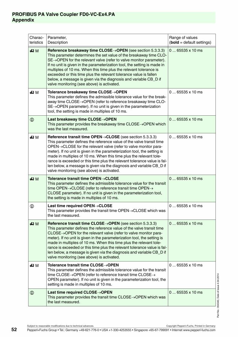
PROFIBUS PA Valve Coupler FD0-VC-Ex4.PAAppendix
Part N
o.: 05
4340
, Date
of is
sue 4
.04.20
14
M Reference breakaway time CLOSEOPEN (see section 5.3.3.3)This parameter determines the set value of the breakaway time CLO-SEOPEN for the relevant valve (refer to valve monitor parameter). If no unit is given in the parameterization tool, the setting is made in multiples of 10 ms. When this time plus the relevant tolerance is exceeded or this time plus the relevant tolerance value is fallen below, a message is given via the diagnosis and variable CB_D if valve monitoring (see above) is activated.
0 ... 65535 x 10 ms
M Tolerance breakaway time CLOSEOPENThis parameter defines the admissible tolerance value for the break-away time CLOSEOPEN (refer to reference breakaway time CLO-SEOPEN parameter). If no unit is given in the parameterization tool, the setting is made in multiples of 10 ms.
0 ... 65535 x 10 ms
Last breakaway time CLOSEOPEN This parameter provides the breakaway time CLOSEOPEN which was the last measured.
0 ... 65535 x 10 ms
M Reference transit time OPENCLOSE (see section 5.3.3.3)This parameter defines the reference value of the valve transit time OPENCLOSE for the relevant valve (refer to valve monitor para-meter). If no unit is given in the parameterization tool, the setting is made in multiples of 10 ms. When this time plus the relevant tole-rance is exceeded or this time plus the relevant tolerance value is fal-len below, a message is given via the diagnosis and variable CB_D if valve monitoring (see above) is activated.
0 ... 65535 x 10 ms
M Tolerance transit time OPENCLOSEThis parameter defines the admissible tolerance value for the transit time OPENCLOSE (refer to reference transit time OPENCLOSE parameter). If no unit is given in the parameterization tool, the setting is made in multiples of 10 ms.
0 ... 65535 x 10 ms
Last time required OPENCLOSEThis parameter provides the transit time OPENCLOSE which was the last measured.
0 ... 65535 x 10 ms
M Reference transit time CLOSEOPEN (see section 5.3.3.3)This parameter defines the reference value of the valve transit time CLOSEOPEN for the relevant valve (refer to valve monitor para-meter). If no unit is given in the parameterization tool, the setting is made in multiples of 10 ms. When this time plus the relevant tole-rance is exceeded or this time plus the relevant tolerance value is fal-len below, a message is given via the diagnosis and variable CB_D if valve monitoring (see above) is activated.
0 ... 65535 x 10 ms
M Tolerance transit time CLOSEOPENThis parameter defines the admissible tolerance value for the transit time CLOSEOPEN (refer to reference transit time CLOSEOPEN parameter). If no unit is given in the parameterization tool, the setting is made in multiples of 10 ms.
0 ... 65535 x 10 ms
Last time required CLOSEOPENThis parameter provides the transit time CLOSEOPEN which was the last measured.
0 ... 65535 x 10 ms
Charac-teristics
Parameter,Description
Range of values(bold = default settings)
52Subject to reasonable modifications due to technical advances. Copyright Pepperl+Fuchs, Printed in Germany
Pepperl+Fuchs Group • Tel.: Germany +49-621-776-0 • USA +1-330-4253555 • Singapore +65-67-799091 • Internet www.pepperl-fuchs.com

PROFIBUS PA Valve Coupler FD0-VC-Ex4.PAAppendix
Part N
o.: 05
4340
, Date
of is
sue 4
.04.20
14
M Manufacturer (regulation unit)The manufacturer of the regulation unit can be stored as text in this parameter for documentation purposes.
(16 characters)
M Product type (regulation unit)The type code of the manufacturer of the regulation unit can be stored as text in this parameter.
(16 characters)
M Serial number (regulation unit)The serial number of the regulation unit can be stored as text in this parameter.
(16 characters)
Charac-teristics
Parameter,Description
Range of values(bold = default settings)
53Subject to reasonable modifications due to technical advances. Copyright Pepperl+Fuchs, Printed in Germany
Pepperl+Fuchs Group • Tel.: Germany +49-621-776-0 • USA +1-330-4253555 • Singapore +65-67-799091 • Internet www.pepperl-fuchs.com

PROFIBUS PA Valve Coupler FD0-VC-Ex4.PAAppendix
Part N
o.: 05
4340
, Date
of is
sue 4
.04.20
14
9.2 Literature
/1/ Bender, Klaus:PROFIBUSISBN: 3446191828, 1999
/2/ Popp, Manfred:PROFIBUS-DP Grundlagen, Tips und Tricks für AnwenderISBN 3778526766, Hüthig Verlag, 1998
/3/ PROFIBUS Nutzerorganisation e.V.:PROFIBUS-PA Profile for Process Control Devices, Version 3.0, October 1999Order No. 3.042, PNO Karlsruhe, 1999, www.profibus.com
/4/ PROFIBUS Nutzerorganisation e.V.:PROFIBUS-PA InbetriebnahmeleitfadenTechnische Richtlinie, Entwurf, Ausgabe 1.1, September 1996Best.-Nr. 2.091, PNO Karlsruhe, 1996, www.profibus.com
54Subject to reasonable modifications due to technical advances. Copyright Pepperl+Fuchs, Printed in Germany
Pepperl+Fuchs Group • Tel.: Germany +49-621-776-0 • USA +1-330-4253555 • Singapore +65-67-799091 • Internet www.pepperl-fuchs.com

PROFIBUS PA Valve Coupler FD0-VC-Ex4.PAAppendix
Part N
o.: 05
4340
, Date
of is
sue 4
.04.20
14
9.3 Glossary
Bus segment Segment
Bus termination Termination resistor
ChannelA channel of the Valve Coupler designates a valve with the two associated PFCs.
DOdigital output, discrete output. The output status can have the value "ON" or "OFF".
EMCElectromagnetic compatibility is the ability of an electrical device to function properly in a speci-fied environment without affecting the environment in an undue manner by emitting electro-ma-gnetical radiation.
FISCOFieldbus lntrinsically Safe Concept.
GSD FileFile in which all slave specific characteristics are stored. A difference is made between manu-facturer specific and profile specific GSD file.
Master Class IA class I master is used for the cyclic user data exchange. The process is controlled via this mas-ter.
Master Class IIA class II master is used for the acyclic communication. It has unrestricted access to all parame-ters and user data at any time unless explicitly prevented by the device.
PFCFinal Position feedback contact. This can be a mechanical switch or a NAMUR sensor.
PNOPROFIBUS Nutzerorganisation e.V. (user organisation) (www.profibus.com).
PROFIBUS"PROcess FIeld BUS", European process and field bus standard, which is stipulated in the PROFIBUS standard (EN 50170). It specifies the functional, electrical and mechanical properties for a bit serial field bus system. PROFIBUS is a bus system, which networks the PROFIBUS com-patible automation systems and field devices in the cell and field level. PROFIBUS are available with the protocols DP (decentralized periphery), FMS (fieldbus message specification) or PA ( process automation).
PROFIBUS DPBus system PROFIBUS with the protocol DP based on standard EN 50170, Volume 2, PROFIBUS. DP means decentralized periphery.
PROFIBUS PAPA means process automation and extends the application of the PROFIBUS family DP by the field of process engineering. Process engineering means both the intrinsically safe areas of the chemical industry and the non intrinsically safe areas, such as for instance, power station auto-mation, foodstuff industry and sewage water equipment.
SegmentA segment or bus segment is a closed part of a serial bus system. The bus line between two ter-mination resistors forms a segment. A segment contains 0 to 32 bus participants. Segments can be coupled via field bus repeaters.
55Subject to reasonable modifications due to technical advances. Copyright Pepperl+Fuchs, Printed in Germany
Pepperl+Fuchs Group • Tel.: Germany +49-621-776-0 • USA +1-330-4253555 • Singapore +65-67-799091 • Internet www.pepperl-fuchs.com

PROFIBUS PA Valve Coupler FD0-VC-Ex4.PAAppendix
Part N
o.: 05
4340
, Date
of is
sue 4
.04.20
14
Segment CouplerA DP/PA Segment Coupler connects a PROFIBUS PA segment with a PROFIBUS DP segment. PROFIBUS PA and PROFIBUS DP coupled with each other in terms of data engineering but se-parated from each other in relation to the physics of transmission.
SlaveA slave must exchange data with a master only after requested so by the latter. Slaves are for instance the Valve Coupler FD0-VC-Ex4.PA and the sensor interface FD0-BI-Ex12.PA from Pep-perl+Fuchs.
TAGClear designation of the control engineering point of the field device within the process plant.
Termination resistorA termination resistor is a resistor to terminate the data transfer line in order to avoid cable reflec-tions; termination resistors are required in any case at the cable or segment ends.
56Subject to reasonable modifications due to technical advances. Copyright Pepperl+Fuchs, Printed in Germany
Pepperl+Fuchs Group • Tel.: Germany +49-621-776-0 • USA +1-330-4253555 • Singapore +65-67-799091 • Internet www.pepperl-fuchs.com

PROFIBUS PA Valve Coupler FD0-VC-Ex4.PAAppendix
Part N
o.: 05
4340
, Date
of is
sue 4
.04.20
14
57Subject to reasonable modifications due to technical advances. Copyright Pepperl+Fuchs, Printed in Germany
Pepperl+Fuchs Group • Tel.: Germany +49-621-776-0 • USA +1-330-4253555 • Singapore +65-67-799091 • Internet www.pepperl-fuchs.com