Proceedings of the Workshop on Knowledge Transformation...
121
I B. Omelayenko, M. Klein (eds.) Proceedings of the Workshop on Knowledge Transformation for the Semantic Web KTSW 2002 Workshop W7 at the 15-th European Conference on Artificial Intelligence 23 July 2002, Lyon, France www.cs.vu.nl/˜borys/events/KTSW02
Transcript of Proceedings of the Workshop on Knowledge Transformation...

I
B. Omelayenko, M. Klein (eds.)
Proceedings of the Workshop on KnowledgeTransformation for the Semantic Web
KTSW 2002
Workshop W7 at the 15-th European Conference on ArtificialIntelligence
23 July 2002, Lyon, France
www.cs.vu.nl/˜borys/events/KTSW02

Preface
The vision of the Semantic Web envisages the Web enriched with numerous domain ontologies, which specify formal se-mantics of data, allowing various intelligent services to perform knowledge-level information transformation, search andretrieval. Recent successful projects in the ontology area have resulted at creation of thousands ontologies, development ofseveral ontology-based annotation tools and inference engines.
However, the absence of an efficient transformation technology for distributed and evolving knowledge hampers furtherdevelopments of the Semantic Web area. Preliminary non-automated knowledge transformation approaches, experimentalresearch prototypes and early proposals of transformation languages need to evolve into a working technology with solidtheoretical grounds and powerful tool support.
The workshop attracted a number of high-quality submissions concerning different transformation issues and models pre-sented in the present book. The book is opened with an extended abstract of the invited talk of F. Casati presenting a discussionabout the role of services at the Semantic Web.
The first section of the proceedings is devoted to model transformation approaches. The paper on ‘Effective schema conver-sions between XML and relational models’ by D. Lee, M. Mani, and W. Chu is followed by the paper on ‘Transforming UMLdomain descriptions into configuration knowledge bases for the Semantic Web’ by A. Felfernig, G. Friedrich, D. Jannach, M.Stumptner, and M. Zanker. Generic model transformation issues are discussed in the paper ‘On modeling conformance forflexible transformation over data models’ by S. Bowers and L. Declambre.
Specific modeling issues are again discussed in the second section. Namely, the problem of ‘Tracking changes in RDF(S)repositories’ by A. Kiryakov and D. Ognyanov, ‘Tracing data lineage using schema transformation pathways’ by H. Fan andA. Poulovassilis, and ‘An algebra for the composition of ontologies’ by P. Mitra and G. Wiederhold.
The next section of the book is devoted to the papers on mapping conceptual models. First, ‘Knowledge representationand transformation in ontology-based data integration’ by S. Castano and A. Ferrara, then ‘MAFRA -An Ontology MAp-ping FRAmework in the context of the Semantic Web’ by A. Maedche, B. Motik, N. Silva and R. Volz. These are followedby application-driven approaches ‘Conceptual normalization of XML data for interoperability in tourism’ by O. Fodor, M.Dell’Erba, F. Ricci, A. Spada and H. Werthner; and ‘RDFT: a mapping meta-ontology for business integration’ by B. Ome-layenko.
The fourth section contains the papers discussing configuration issues: ‘Enabling services for distributed environments:ontology extraction and knowledge-base characterization’ by D. Sleeman, D. Robertson, S. Potter and M. Schorlemmer;‘The ‘Family of Languages’ approach to semantic interoperability’ by J. Euzenat and H. Stuckenschmidt; and ‘A logicprogramming approach on RDF document and query transformation’ by J. Peer.
The last section is devoted to poster presentations and system demonstrations: ‘Information retrieval system based on graphmatching’ by T. Miyata and K. Hasida; ‘Formal knowledge management in distributed environments’ by M. Schorlemmer, S.Potter, D. Robertson, and D. Sleeman; ‘Distributed semantic perspectives’ by O. Hoffmann and M. Stumptner; ‘The ontologytranslation problem’ by O. Corcho.
We would like to thank the authors for their contributions and wish you to enjoy reading the book.
June 2002 Borys Omelayenko,Michel Klein,
co-chairs of workshop

Organization
The workshop on Knowledge Transformation for the Semantic Web was held on July 23-th during the 15-th EuropeanConference on Artificial Intelligence, Lyon, France, 21-26 July 2002.
Program Commitee
Michael Blaha OMT Associates, USAHarold Boley German Research Center for Artificial Intelligence, GermanyChristoph Bussler Oracle Corporation, USAHans Chalupsky University of Southern California (ISI), USADetlef Plump The University of York, UKDieter Fensel Vrije Universiteit Amsterdam, NLNatasha F. Noy Stanford University (SMI), USAMichel Klein Vrije Universiteit Amsterdam, NLBorys Omelayenko Vrije Universiteit Amsterdam, NLAlex Poulovassilis University of London (Birkbeck Colledge), UKChantal Reynaud University Paris-Sud, FranceMichael Sintek German Research Center for Artificial Intelligence, GermanyHeiner Stuckenschmidt Vrije Universiteit Amsterdam, NLGerd Stumme University of Karsruhe (AIFB), Germany
Additional referees
Danny AyersShawn BowersJeen BroekstraMario CannataroWesley ChuOscar CorchoJerome EuzenatHao Fan
Alfio FerraraOliver FodorOliver HoffmannAlexander MadchePrasenjit MitraTakashi MiyataDamyan OgnyanoffBorys Omelayenko
Joachim PeerStephen PotterRafael PulidoMarco SchorlemmerRonny SiebesCarlo WoutersMarkus Zanker
Sponsoring Institutions
OntoWeb thematic Networkhttp://www.ontoweb.org/
Bibliographic Reference
Proceedings of the Workshop on Knowledge Transformation for the Semantic for the Semantic Web at the 15thEuropean Conference on Artificial Intelligence (KTSW-2002), Lyon, France, 23 July 2002. Available online athttp://www.cs.vu.nl/˜borys/events/ktsw2002.pdf
Workshop Homepage
http://www.cs.vu.nl/˜borys/events/KTSW02

Table of Contents
Invited Talk
A Conversation on Web Services: what’s new, what’s true, what’s hot. And what’s not. . . . . . . . . . . . . . . . . . . . . . . . . . 1Fabio Casati
Modeling I
Effective Schema Conversions between XML and Relational Models. . . . . . . . . . . . . . . . . . . . . . . . . . . . . . . . . . . . . . . 3Dongwon Lee, Murali Mani, Wesley W. Chu
Transforming UML domain descriptions into Configuration Knowledge Bases for the Semantic Web. . . . . . . . . . . . . . 11Alexander Felfernig, Gerhard Friedrich, Dietmar Jannach, Markus Stumptner, Markus Zanker
On Modeling Conformance for Flexible Transformation over Data Models. . . . . . . . . . . . . . . . . . . . . . . . . . . . . . . . . . . 19Shawn Bowers and Lois Delcambre
Modeling II
Tracking Changes in RDF(S) Repositories. . . . . . . . . . . . . . . . . . . . . . . . . . . . . . . . . . . . . . . . . . . . . . . . . . . . . . . . . . . . . 27Atanas Kiryakov, Damyan Ognyanov
Tracing Data Lineage Using Schema Transformation Pathways. . . . . . . . . . . . . . . . . . . . . . . . . . . . . . . . . . . . . . . . . . . . 36Hao Fan, Alexandra Poulovassilis
An Algebra for the Composition of Ontologies. . . . . . . . . . . . . . . . . . . . . . . . . . . . . . . . . . . . . . . . . . . . . . . . . . . . . . . . . 43Prasenjit Mitra and Gio Wiederhold
Mapping
Knowledge Representation and Transformation in Ontology-based Data Integration. . . . . . . . . . . . . . . . . . . . . . . . . . . . 51Silvana Castano, Alfio Ferrara
MAFRA — A MApping FRAmework for Distributed Ontologies in the Semantic Web. . . . . . . . . . . . . . . . . . . . . . . . . 60Alexander Maedche, Boris Motik, Nuno Silva, Raphael Volz
Conceptual Normalisation of XML Data for Interoperability in Tourism. . . . . . . . . . . . . . . . . . . . . . . . . . . . . . . . . . . . . 69Oliver Fodor, Mirella Dell’Erba, Francesco Ricci, Antonella Spada, Hannes Werthner
RDFT: A Mapping Meta-Ontology for Business Integration. . . . . . . . . . . . . . . . . . . . . . . . . . . . . . . . . . . . . . . . . . . . . . . 77Borys Omelayenko
Configuring
Enabling Services for Distributed Environments: Ontology Extraction and Knowledge Base Characterisation. . . . . . . . 85Derek Sleeman, Stephen Potter, Dave Robertson, W. Marco Schorlemmer
The ‘Family of Languages’ Approach to Semantic Interoperability. . . . . . . . . . . . . . . . . . . . . . . . . . . . . . . . . . . . . . . . . 93Jerome Euzenat, Heiner Stuckenschmidt
A Logic Programming Approach To RDF Document And Query Transformation. . . . . . . . . . . . . . . . . . . . . . . . . . . . . . 101Joachim Peer
Posters
Information Retrieval System Based on Graph Matching. . . . . . . . . . . . . . . . . . . . . . . . . . . . . . . . . . . . . . . . . . . . . . . . . 110Takashi Miyata, Koiti Hasida
Formal Knowledge Management in Distributed Environments. . . . . . . . . . . . . . . . . . . . . . . . . . . . . . . . . . . . . . . . . . . . 111W. Marco Schorlemmer, Stephen Potter, David Robertson, Derek Sleeman
Distributed Semantic Perspectives. . . . . . . . . . . . . . . . . . . . . . . . . . . . . . . . . . . . . . . . . . . . . . . . . . . . . . . . . . . . . . . . . . . 112Oliver Hoffmann and Markus Stumptner

V
A framework to solve the ontology translation problem. . . . . . . . . . . . . . . . . . . . . . . . . . . . . . . . . . . . . . . . . . . . . . . . . . 114Oscar Corcho
Author Index . . . . . . . . . . . . . . . . . . . . . . . . . . . . . . . . . . . . . . . . . . . . . . . . . . . . . . . . . . . . . . . . . . . . . . . . . . . . . . . . . 115

VI

A Conversation on Web Services: what’s new, what’s true, what’s hot.And what’s not
Fabio Casati
Hewlett-Packard1501 Page Mill Road, MS 1142
Palo Alto, CA, USA, 94304Fabio [email protected]
Hi Tim, what are you doing?I am writing a paper on Web Services. They are the next
wave of Internet-based applications.Oh! I heard about them, but I was never really able to
understand what they are. What’s a web service?Ah. I get this question a lot. It reminds me of when peo-
ple were asking me ”what is an agent?”. Well, a Web serviceis an application that exposes functionalities accessible viathe Internet, using standard Web protocols (that’s why theyare calledWebservices). In particular, the names that are al-ways made are those of XML, SOAP, and WSDL. If your ap-plication has an interface described in WSDL, and interactswith clients by exchanging XML messages encapsulated intoSOAP envelopes, then it is a web service.
I see. Doesn’t seem too exciting, anyway. What’s newabout it? Sounds just like good old RPC over the Web, onlyunder a different form.
Well, that’s true. Conceptually, and technologically, thereis nothing particularly new. Perhaps, the biggest difference isthat these languages and protocols are supported by prettymuch every big software player. This level of support isunprecedented. You don’t have to deal with things such asCORBA vs DCOM, java vs C++ vs C#, Solaris vs Windowsvs HP-UX vs Linux. With web services standards you goacross platforms, from the top to the bottom of the softwarestack. Application integration becomes easier, because ev-erybody speaks the same language, or at least they use thesame grammar. Think about it: One of the problems you havein application integration is that enterprise processes need toaccess many different systems, each supporting its own lan-guage and protocols. Therefore, either you write ad-hoc codefor each of them, or you buy an integration platform alongwith system-specific adapters that hide the heterogeneity andshow to the integrating application a uniform view of an oth-erwise diverse world. But, with XML, SOAP, and WSDL,these adapters will become much simpler, considerably lessexpensive, and easier to deploy. After all, if Web services be-come reality, what adapters will end up doing are translationsbetween different XML formats.
Another aspect to keep in mind is that all these languagesand protocols are simple. Simplicity is paramount. If you tryto make standards too complex, they won’t fly. They will bedifficult to understand and difficult to implement. SOAP andWSDL are just at the right level to gain acceptance and stim-ulate the development of design and runtime tools.
mmmm. Yes, makes sense. So, they simplify enterprise ap-plication integration and reduce the need for integrationplatforms. That’s a great benefit. Indeed, it’s one of thebiggest headaches in many of my projects. But tell me onemore thing: I never really hear about web services in the con-
text of enterprise application integration. Everybody seemsto talk about “dynamic discovery”, “loosely-coupled”, “Se-mantic”, and that’s where the hype seems to be.
Yes, Web services were not born with enterprise applica-tion integration in mind. The original goal was (and still is, tosome extent) to get to a do-it-for-me Internet. Basically, youshould be able to tell your “agent” what you need. Then, thisagent will search the Web for the available service that bestsuits your need, finds out if and how it can talk to the ser-vice, invokes the desired functionality, pays for the service,and then brings the results back to you.
Wow! Sounds like magic. How is it done?Well, with Web services, not only you describe the ap-
plication interface in a standard language (WSDL) and ac-cess its functionalities through a standard protocol (SOAP),but you can also describe it in Internet registries, structuredaccording to another standards, called UDDI. In this way,clients requiring a service can just go to an UDDI directory,enter their search criteria, retrieve the list of services that sat-isfy their needs, and access these service.
OK, but didn’t you have that with other naming and direc-tory services? JNDI and CORBA for example have similarcapabilities
Yes. One of the differences, however, lies in the way UDDIis designed. In fact, its purpose is to enable the dynamic dis-covery of services over the Web, across platforms and acrossorganizations. It’s been created from the start with this pur-pose in mind. Entries in the directory can be posted by anycompany, and services can be deployed on all sorts of plat-forms. Therefore, the description needs to be independent ofspecific languages or platform. Other issues are the need forflexibility and extensibility. You don’t want to fix a servicedescription language, data structure, or ontology because youjust don’t know what will be needed to describe a particularweb service or set of web services. For example, sometimesin the future a shoe store standardization consortium may de-fine a standard set of properties of shoes and shoe stores, aswell as a description of the behavior that Web shoe storesshould have. Right now, not only we do not have a clue aboutwhat are the characteristics that users will need to describeshoes and Web shoe stores, but we do not even know whatlanguage will be suited to specify their behaviors. Maybethese standardization consortia will want or need to definethe semantics in a very detailed manner, using some languagethat we cannot imagine right now. UDDI let’s you do it withthe notion oftModel: any UDDI client (the standardizationbody in this example) can define a document (the tModel)that describes the properties that a web shoe store may ormust have, in terms of attributes, interfaces, supported pro-tocols, transactionality, and other attributes that maybe we

2 Fabio Casati
cannot even imagine right now, but that will be importantin the future. The structure of this document is open for themost part, and is not interpreted by UDDI. Therefore, youcan write specifications in any language. Let’s assume thatthis tModel has been defined, and assigned some identifier(say, 643).
When you describe a web service, you can specify thatyour service has the propertytModel 643, meaning that youare compliant with that tModel, and therefore with the speci-fication by the shoe standardization consortium. In this way,clients that have been designed to interact with web shoestores can look for service provider that supports tModel 643.You can even go into more details, for example specifyingthat you sell shoes that, according to the definition of “color”given in tModel 643, are “yellow”.
Another important characteristic of UDDI is that it alsodefines how to operate and maintain global directories. Youneed this if you want client applications to be able to findand access services wherever they are, based only on theirproperties and not on whether you can locate them or not. It’syet another manifestation of the democracy of the Internet!Big vendors and small shops will look alike, you only selectthem based on what they offer.
Well, I am a little skeptical about this, Tim. I am sure thatbig guys will find a way to make you buy from them. But letme understand this tModel. From what you are saying, clientapplications are not really going to read tModel 643. Theyjust want to know whether a service is compliant with it ornot. Basically, it is a human that, when developing the clientapplication, reads the tModel to understand how to interactwith web shoe stores, and then writes the application code ina way that it can communicate with such web services. So,the tModel description is meant for humans, isn’t it?
That’s one use of the tModel. It has benefits in its ownright. However, you can use tModels in a more powerfulway. For example, if your tModel specifies a WSDL inter-face, then you can think of tools that simplify the develop-ment efforts by reading a tModel and automatically generat-ing the stubs to be plugged into your client application. Thenext (and most interesting) step consists in formalizing moreaspects of a web service within a tModel. In this way, ap-plications could be able to read the tModel associated to aservice, find out the interfaces and interaction protocols sup-ported by this service, and understand how to invoke the de-sired functionality.
See, Tim this is what looks like magic to me. I hear thisa lot, but I don’t see how it can happen. Let me tell youabout my last project. We had to automate our supply chainoperations, invoking our business partners automatically forsuch things as sending and receiving quotes, executing pur-chase orders, and the like. We decided to use the RosettaNetstandard to perform these B2B interactions. As you proba-bly know, RosettaNet defines a large number of very detailedinterfaces and protocols for supply chain operations in theIT domain. It has full industry support, it has been carefullydesigned by all industry leaders, and it has gone throughseveral revisions so that it is now at a good level of matu-rity. There are also many commercial platforms that supportRosettaNet out-of-the-box, and integrate B2B conversationswith the execution of your internal processes. Our partnersand us had two different platforms supporting this standard.
When we tried to perform the B2B interactions, well, nothingworked!! Even if both platforms supported RosettaNet, un-less both of us had the same system from the same vendors,we could not communicate.
But that was only one of the problems! Even with identicalplatforms, we still had to do a lot of work to get things go-ing. The fact is that, even in mature vertical standards, spec-ifications are often ambiguous. In addition, many practicalcases have needs that are not supported by the standard. Forexample, in this project we had to meet face-to-face severaltimes with our partners to actually agree on what is the ex-act meaning of what we write in the RosettaNet-compliantXML documents that are exchanged. Furthermore, in somecases there were some attributes that we needed to transfer,and there was no place for them in the XML document as de-signed by RosettaNet. For example, we agreed that we woulduse a “date” field to enter a line item number.
That’s why I am skeptical about all this “dynamic interac-tion” and “semantic specifications”. In many practical situa-tions, not only you are not able to dynamically discover howto talk to your partner, but you are not even able to invokea service that follows the exact same interface and protocolthat your application has been designed to support.
I see. That’s an interesting perspective. So, you think thatit is not possible to perform any kind of dynamic B2B dis-covery and interaction over the Web?
Well, no, I would not go that far. I think that you can indeeduse UDDI to dynamically search for a service that supportsthe standard your client application has been designed to in-teract with. And the support you have in UDDI seems just fineto me. What I am saying is that this can happen for relativelysimple cases and for services that are not mission-critical. Iwould not use it to dynamically find my supply chain partnersand interact with them, but I can use it for a PS to PDF con-verter, or for finding out the movie schedule. Even there, ifyou put payments into the picture, things become more com-plex. And not many companies will provide web services forfree, given that since the interaction is automated, they can-not even show advertisements to you. The other point youmade, about dynamically discovering how to interact witha newly discovered service implementing a protocol that myclient was not designed to support, well, that I think will nothappen for quite some time. You may find some simple casesfor which it works, but I doubt you can have any real deploy-ment around it.
From what you say, this is a generic problem, independentof Web services, SOAP, or UDDI.
Yes the problem is always the same. It’s hard to do businessautomatically with people you don’t know and with whomyou do not have a contract in place. Not to mention theproblem of resolving disputes. But I can see that there aremany contexts in which Web service technology is applicable.Enterprise application integration is one of them. You haveconvinced me that Web services provide significant benefitsthere. I can see how I can integrate quickly and with lowercosts. The same concept, I think, can be extended to closedcommunities of business partners, where agreements are inplace before the interaction starts, and where the details canbe worked out by humans.
After all, do you think that Web services are here to stay?Yes, definitely. They are here to stay.
Effective Schema Conversions between XML and Relational Models
Dongwon Lee?, Murali Mani??, and Wesley W. Chu
UCLA, Computer Science Department,{dongwon, mani, wwc }@cs.ucla.edu
Abstract. As Extensible Markup Language(XML) is emerging as the data format of the Inter-net era, there is an increasing need to efficientlystore and query XML data. At the same time,as requirements change, we expect a substantialamount of conventionalrelational data to beconverted or published as XML data. One path toaccommodate these changes is to transform XMLdata into relational format (and vice versa) to usethe mature relational database technology.In this paper, we present three semantics-basedschema transformation algorithms towards thisgoal: 1) CPI converts an XML schema to a re-lational schema while preserving semantic con-straints of the original XML schema, 2)NeT de-rives a nested structured XML schema from a flatrelational schema by repeatedly applying thenestoperator so that the resulting XML schema becomeshierarchical, and 3)CoT takes a relational schemaas input, where multiple tables are interconnectedthrough inclusion dependencies and generates anequivalent XML schema as output.
1 Introduction
Recently, XML [1] has emerged as thede factostandard fordata format on the web. The use of XML as the common for-mat for representing, exchanging, storing, and accessing dataposes many new challenges to database systems. Since themajority of everyday data is still stored and maintained in re-lational database systems, we expect that the needs to convertdata format between XML and relational models will growsubstantially. To this end, several schema transformation al-gorithms have been proposed (e.g., [2,3,4,5]). Although theywork well for the given applications, the XML-to-Relationalor Relational-to-XML transformation algorithms only cap-ture thestructureof the original schema and largely ignorethe hiddensemantic constraints. Consider the following ex-ample for XML-to-Relational conversion case.
Example 1.Consider a DTD that models conference publi-cations:
<!ELEMENT conf(title,soc,year,mon?,paper+)><!ELEMENT paper(pid,title,abstract?)>
Suppose the combination oftitle andyear uniquelyidentifies theconf . Using the hybrid inlining algorithm [4],the DTD would be transformed to the following relationalschema:
conf (title,soc,year,mon)paper (pid,title,conf_title,conf_year,
abstract)? This author is partially supported by DARPA contract No.
N66001-97-C-8601.?? This author is partially supported by NSF grants 0086116,
0085773, 9817773.
While the relational schema correctly captures thestructural aspect of the DTD, it does not enforce cor-rect semantics. For instance, it cannot prevent a tu-ple t1: paper(100,’DTD...’,’ER’,3000,’...’)from being inserted. However, tuplet1 is inconsistentwith the semantics of the given DTD since the DTDimplies that the paper cannot exist without being as-sociated with a conference and there is apparently noconference “ER-3000” yet. In database terms, this kindof violation can be easily prevented by aninclusiondependencysaying “paper[conf title,conf year]⊆ conf[title,year] ”.
The reason for this inconsistency between the DTD andthe transformed relational schema is that most of the pro-posed transformation algorithms, so far, have largely ignoredthe hiddensemantic constraintsof the original schema.
1.1 Related Work
Between XML and Non-relational Models: Conversion be-tween different models has been extensively investigated. Forinstance, [6] deals with transformation problems in OODBarea; since OODB is a richer environment than RDB, theirwork is not readily applicable to our application. The logicaldatabase design methods and their associated transformationtechniques to other data models have been extensively stud-ied in ER research. For instance, [7] presents an overview ofsuch techniques. However, due to the differences between ERand XML models, those transformation techniques need tobe modified substantially. More recently, [8] studies a genericmapping between arbitrary models with the focus of devel-oping a framework for model management, but is not directlyrelevant to our problems.
From XML to Relational : From XML to relational schema,several conversion algorithms have been proposed recently.STORED [2] is one of the first significant attempts to storeXML data in relational databases. STORED uses a data min-ing technique to find a representative DTD whose supportexceeds the pre-defined threshold and using the DTD, con-verts XML documents to relational format. Because [9] dis-cusses template language-based transformation from DTDto relational schema, it requires human experts to write anXML-based transformation rule. [4] presents three inliningalgorithms that focus on the table level of the schema con-versions. On the contrary, [3] studies different performanceissues among eight algorithms that focus on the attribute andvalue level of the schema. Unlike these, we propose a methodwhere the hidden semantic constraints in DTDs are systemat-ically found and translated into relational formats [10]. Sincethe method is orthogonal to the structure-oriented conversionmethod, it can be used along with algorithms in [2,9,4,3].
From Relational to XML : There have been different ap-proaches for the conversion from relational model to XML

4 Dongwon Lee et al.
RDB
CPI
NeT & CoT
SchemaDesigner XML
Schemas
Fig. 1.Overview of our schema translation algorithms.
model, such as XML Extender from IBM, XML-DBMS,SilkRoute [11], and XPERANTO [5]. All the above toolsrequire the user to specify the mapping from the given re-lational schema to XML schema. In XML Extender, theuser specifies the mapping through a language such as DADor XML Extender Transform Language. In XML-DBMS, atemplate-driven mapping language is provided to specify themappings. SilkRoute provides a declarative query language(RXL) for viewing relational data in XML. XPERANTOuses XML query language for viewing relational data inXML. Note that in SilkRoute and XPERANTO, the user hasto specify the query in the appropriate query language.
2 Overview of Our Schema TranslationAlgorithms
In this paper, we present three schema transformation algo-rithms that not only capture the structure, but also the seman-tics of the original schema. The overview of our proposals isillustrated in Figure 1.
1. CPI (Constraints-preserving Inlining Algorithm): iden-tifies various semantics constraints in the original XMLschema and preserves them by rewriting them in the finalrelational schema.
2. NeT (Nesting-based Translation Algorithm): derives anested structure from a flat relational schema by repeat-edly applying thenest operator so that the resultingXML schema becomes hierarchical. The main idea isto find a more intuitive element content model of theXML schema that utilizes the regular expression oper-ators provided by the XML schema specification (e.g.,“*” or “+”).
3. CoT (Constraints-based Translation Algorithm): Al-thoughNeT infers hidden characteristics of data by nest-ing, it is only applicable to a single table at a time. There-fore, it is unable to capture the overall picture of rela-tional schema where multiple tables are interconnected.To remedy this problem,CoT considers inclusion depen-dencies during the translation, and merges multiple inter-connected tables into a coherent and hierarchical parent-child structure in the final XML schema.
3 TheCPI Algorithm
Transforming a hierarchical XML model to a flat relationalmodel is not a trivial task due to several inherent dif-ficulties such as non-trivial 1-to-1 mapping, existence of
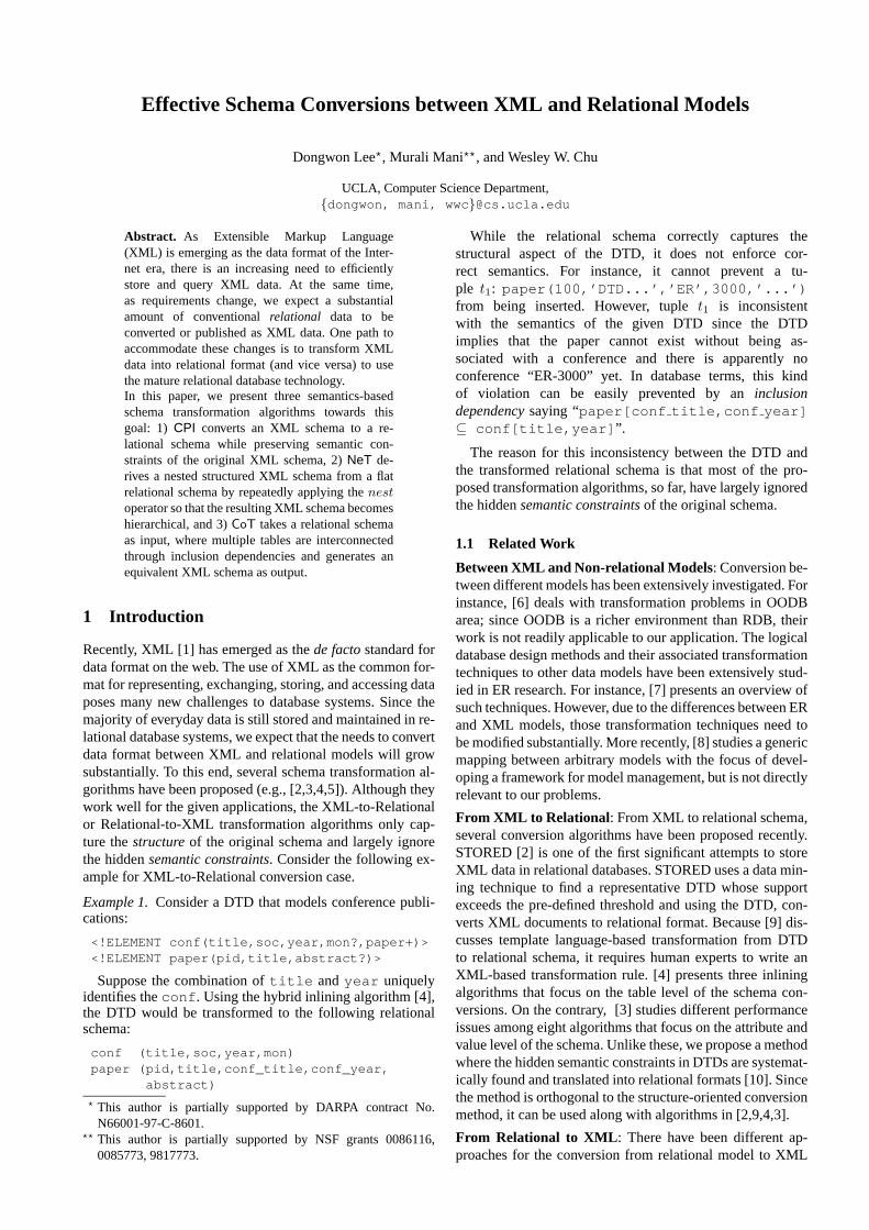
<!ELEMENT conf (title,date,editor?,paper*)><!ATTLIST conf id ID #REQUIRED><!ELEMENT title (#PCDATA)><!ELEMENT date EMPTY><!ATTLIST date year CDATA #REQUIRED
mon CDATA #REQUIREDday CDATA #IMPLIED>
<!ELEMENT editor (person*)><!ATTLIST editor eids IDREFS #IMPLIED><!ELEMENT paper (title,contact?,author,cite?)><!ATTLIST paper id ID #REQUIRED><!ELEMENT contact EMPTY><!ATTLIST contact aid IDREF #REQUIRED><!ELEMENT author (person+)><!ATTLIST author id ID #REQUIRED><!ELEMENT person (name,(email|phone)?)><!ATTLIST person id ID #REQUIRED><!ELEMENT name EMPTY><!ATTLIST name fn CDATA #IMPLIED
ln CDATA #REQUIRED><!ELEMENT email (#PCDATA)><!ELEMENT phone (#PCDATA)><!ELEMENT cite (paper*)><!ATTLIST cite id ID #REQUIRED
format (ACM|IEEE) #IMPLIED>
Table 1.A DTD for Conference .
set values, complicated recursion, and/or fragmentation is-sues [4]. Most XML-to-Relational transformation algorithms(e.g., [9,2,3,4]) have so far mainly focused on the issue ofstructural conversion, largely ignoring the semantics alreadyexisted in the original XML schema. Let us first describe var-ious semantic constraints that one can mine from the DTD.Throughout the discussion, we will use the example DTDand XML document in Tables 1 and 2.
3.1 Semantic Constraints in DTDs
Cardinality Constraints : In a DTD declaration, there areonly 4 possible cardinality relationships between an elementand its sub-elements as illustrated below:
<!ELEMENT article (title, author+,ref*, price?)>
1. (0,1): An element can have either zero or one sub-element. (e.g., sub-elementprice )
2. (1,1): An element must have one and only one sub-element. (e.g., sub-elementtitle )
3. (0,N): An element can have zero or more sub-elements.(e.g., sub-elementref )
4. (1,N): An element can have one or more sub-elements.(e.g., sub-elementauthor )
Following the notations in [7], let us call each cardinal-ity relationship as type (0,1), (1,1), (0,N), (1,N), respectively.From these cardinality relationships, mainly three constraintscan be inferred. First is whether or not the sub-element can benull. We use the notation “X 9 ∅” to denote that an elementX cannot be null. This constraint is easily enforced by theNULL or NOT NULLclause in SQL. Second is whether ornot more than one sub-element can occur. This is also knownassingleton constraintin [12] and is one kind of equality-generating dependencies. Third, given an element, whetheror not its sub-element should occur. This is one kind of tuple-generating dependencies. The second and third types will befurther discussed below.
Inclusion Dependencies (INDs): An Inclusion Dependencyassures that values in the columns of one fragment must also
Schema Conversions 5
<conf id="er05"><title>Int’l Conf. on Conceptual Modeling</title><date>
<year>2005</year> <mon>May</mon> <day>20</day></date><editor eids="sheth bossy">
<person id="klavans"><name fn="Judith" ln="Klavans"/><email>[email protected]</email>
</person> </editor><paper id="p1">
<title>Indexing Model for Structured...</title><contact aid="dao"/><author>
<person id="dao"><name fn="Tuong" ln="Dao"/></author>
</paper><paper id="p2">
<title>Logical Information Modeling...</title><contact aid="shah"/><author>
<person id="shah"><name fn="Kshitij" ln="Shah"/>
</person><person id="sheth">
<name fn="Amit" ln="Sheth"/><email>[email protected]</email>
</person></author><cite id="c100" format="ACM">
<paper id="p3"><title>Making Sense of Scientific...</title><author>
<person id="bossy"><name fn="Marcia" ln="Bossy"/><phone>391.4337</phone>
</person></author> </paper> </cite> </paper>
</conf><paper id="p7">
<title>Constraints-preserving Trans...</title><contact aid="lee"/><author>
<person id="lee"><name fn="Dongwon" ln="Lee"/><email>[email protected]</email>
</person> </author><cite id="c200" format="IEEE"/>
</paper>...
Table 2. An example XML document conforming to the DTD inTable 1.
appear as values in the columns of other fragments and is ageneralization of the notion ofreferential integrity.
Trivial form of INDs found in the DTD is that “givenan elementX and its sub-elementY , Y must be includedin X (i.e., Y ⊆ X)”. For instance, from theconf elementand its four sub-elements in theConference DTD, thefollowing INDs can be found as long asconf is not null:{conf.title ⊆ conf, conf.date ⊆ conf,conf.editor ⊆ conf, conf.paper ⊆ conf }.Another form of INDs can be found in the attribute definitionpart of the DTD with the use of theIDREF(S) keyword.For instance, consider thecontact andeditor elementsin theConference DTD shown below:
<!ELEMENT person (name,(email|phone)?><!ATTLIST person id ID #REQUIRED><!ELEMENT contact EMPTY><!ATTLIST contact aid IDREF #REQUIRED><!ELEMENT editor (person*)><!ATTLIST editor eids IDREFS #IMPLIED>
The DTD restricts theaid attribute of the con-tact element such that it can only point to theid attribute of the person element1. Further, theeids attribute can only point to multipleid attributesof the person element. As a result, the followingINDs can be derived:{editor.eids ⊆ person.id,contact.aid ⊆ person.id }. Such INDs can be bestenforced by the “foreign key” if the attribute being refer-enced is a primary key. Otherwise, it needs to use theCHECK,ASSERTION, or TRIGGERSfacility of SQL.
1 Precisely, an attribute withIDREF type does not specify whichelement it should point to. This information is available only byhuman experts. However, new XML schema languages such asXML-Schema and DSD can express where the reference actuallypoints to [13].
Equality-Generating Dependencies (EGDs): The Single-ton Constraint[12] restricts an element to have “at most”one sub-element. When an element typeX satisfies the sin-gleton constraint towards its sub-element typeY , if an ele-ment instancex of typeX hastwo sub-elements instancesy1 and y2 of type Y , then y1 and y2 must be the same.This property is known asEquality-Generating Dependen-cies (EGDs)and denoted by “X → Y ” in database the-ory. For instance, two EGDs:{conf → conf.title,conf → conf.date } can be derived from theconf el-ement in Table 1. This kind of EGDs can be enforced by SQLUNIQUEconstruct. In general, EGDs occur in the case of the(0,1) and (1,1) mappings in the cardinality constraints.
Tuple-Generating Dependencies (TGDs): TGDs in a rela-tional model require that some tuples of a certain form bepresent in the table and use the “�” symbol. Two usefulforms of TGDs from DTD are thechild and parent con-straints[12].
1. Child constraint: "Parent � Child" states thatevery element of typeParent must have at least onechild element of typeChild. This is the case of the (1,1)and (1,N) mappings in the cardinality constraints. For in-stance, from the DTD in Table 1, because theconf ele-ment must contain thetitle anddate sub-elements,the child constraintconf � {title, date } holds.
2. Parent constraint: "Child � Parent" states thatevery element of typeChild must have a parent el-ement of typeParent. According to XML specifica-tion, XML documents can start from any level of ele-ment without necessarily specifying its parent element,when a root element is not specified by<!DOCTYPEroot> . In the DTD in Table 1, for instance, theed-itor anddate elements can have theconf elementas their parent. Further, if we know that all XML docu-ments were started at theconf element level, rather thanthe editor or date level, then the parent constraint{editor, date }� conf holds. Note that theti-tle � conf does not hold since thetitle elementcan be a sub-element of either theconf or paper ele-ment.
3.2 Discovering and Preserving Semantic Constraintsfrom DTDs
The CPI algorithm utilizes a structure-based conversion al-gorithm as a basis and identifies various semantic constraintsdescribed in Section 3.1. We will use thehybridalgorithm [4]as the basis algorithm.CPI first constructs aDTD graphthatrepresents the structure of a given DTD. A DTD graph canbe constructed when parsing the given DTD. Its nodes areelements, attributes, or operators in the DTD. Each elementappears exactly once in the graph, while attributes and oper-ators appear as many times as they appear in the DTD.CPIthen annotates various cardinality relationships (summarizedin Table 3) among nodes to each edge of the DTD graph.Note that the cardinality relationship types in the graph con-sider not only element vs. sub-element relationships but alsoelement vs. attribute relationships. Figure 2 illustrates an ex-ample of such annotated DTD graph for theConferenceDTD in Table 1.

6 Dongwon Lee et al.
Relationship Symbol not null EGDs TGDs(0,1) ? no yes no(1,1) yes yes yes(0,N) * no no no(1,N) + yes no yes
Table 3.Cardinality relationships and their corresponding semanticconstraints.
date
year
mon
day
title
id name
fn ln email
contactaid
eids
person
conf
paper
id
idtop node
(0,1)
(1,1)(1,1)
(0,N)
(1,N)
(0,N)
(0,1)(1,1) editor
(0,N)
(0,1) (0,1)(1,1)
(1,1)(1,1)
author(1,1)
(1,1)
cite
(0,1)(1,1)
(0,1)
(0,1)
(0,N)
(1,1)
(1,1)
(1,1)
(0,1) (1,1) (0,N) (1,N)
? * +
id
(1,1)
format
phone
(0,1)
Fig. 2.An annotatedDTD graphfor theConference DTD in Ta-ble 1.
Once the annotated DTD graph is constructed,CPI fol-lows the basic navigation method provided by thehybrid al-gorithm; it identifiestop nodes[4,10] that are the nodes: 1)not reachable from any nodes (e.g., source node), 2) directchild of “* ” or “ +” operator node, 3) recursive node with in-degree> 1, or 4) one node between two mutually recursivenodes with indegree= 1. Then, starting from each top nodeT , inline all the elements and attributes atleaf nodesreach-able fromT unless they are other top nodes. In doing so, eachannotated cardinality relationship can be properly convertedto its counterpart in SQL syntax as described in Section 3.1.The details of the algorithm is beyond the scope of this pa-per and interested readers are referred to [10]. For instance,Figure 3 and Table 4 are such output relational schema anddata in SQL notation, automatically generated by theCPI al-gorithm.
4 TheNeT Algorithm
The simplest Relational-to-XML translation method, termedas FT (Flat Translation) in [14], is to translate 1) tablesin a relational schema to elements in an XML schema and2) columns in a relational schema to attributes in an XMLschema.FT is a simple and effective translation algorithm.However, sinceFT translates the “flat” relational model to a“flat” XML model in a one-to-one manner, it does not uti-lize several basic “non-flat” features provided by the XMLmodel for data modeling such as representingrepeating sub-elementsthrough regular expression operators (e.g., “*”,“+”). To remedy the shortcomings ofFT, we propose theNeT algorithm that utilizes variouselement content modelsof the XML model.NeT uses thenestoperator [15] to derivea “good” element content model.
Informally, for a tablet with a set of columnsC, nestingon a non-empty columnX ∈ C collects all tuples that agreeon the remaining columnsC −X into a set2. Formally,
2 Here, we only consider single attribute nesting.
CREATE TABLE paper (id NUMBER NOT NULL,title VARCHAR(50) NOT NULL,contact_aid VARCHAR(20),cite_id VARCHAR(20),cite_format VARCHAR(50)
CHECK (VALUE IN ("ACM", "IEEE")),root_elm VARCHAR(20) NOT NULL,parent_elm VARCHAR(20),fk_cite VARCHAR(20)
CHECK (fk_cite IN(SELECT cite_id FROM paper)),
fk_conf VARCHAR(20),PRIMARY KEY (id),UNIQUE (cite_id),FOREIGN KEY (fk_conf)
REFERENCES conf(id),FOREIGN KEY (contact_aid)
REFERENCES person(id));
Fig. 3. Final relational “schema” for thepaper element in theConference DTD in Table 1, generated byCPI algorithm.
Definition 1 (Nest). [15]. Let t be an-ary table with col-umn setC, and X ∈ C and X = C − X. For each(n − 1)-tuple γ ∈ ΠX(t), we define ann-tuple γ∗ as fol-lows: γ∗[X] = γ, andγ∗[X] = {κ[X] | κ ∈ t ∧ κ[X] = γ.Then,nestX(t) = {γ∗ | γ ∈ ΠX(t)}.
After nestX(t), if columnX has only a set with “single”value{v} for all the tuples, then we say thatnesting failedand we treat{v} andv interchangeably (i.e.,{v} = v). Thuswhen nesting failed, the following is true:nestX(t) = t.Otherwise, if columnX has a set with “multiple” values{v1, ..., vk} with k ≥ 2 for at least one tuple, then we saythatnesting succeeded.
Example 2.Consider a tableR in Table 5. Here we assumethat the columnsA, B, C are non-nullable. In computingnestA(R) at (b), the first, third, and fourth tuples ofR agreeon their values in columns (B, C) as (a, 10), while their val-ues of the columnA are all different. Therefore, these differ-ent values are grouped (i.e., nested) into a set{1,2,3}. Theresult is the first tuple of the tablenestA(R) – ({1,2,3},a, 10). Similarly, since the sixth and seventh tuples ofRagree on their values as (b, 20), they are grouped to a set{4,5}. In computingnestB(R) at (c), there are no tuples inR that agree on the values of the columns (A,C). Therefore,nestB(R) = R. In computingnestC(R) at (d), since thefirst two tuples ofR – (1, a, 10) and (1, a, 20) – agree onthe values of the columns (A, B), they are grouped to (1, a,{10,20}). Nested tables (e) through (j) are constructed simi-larly.
Since thenest operator requires scanning of the entire setof tuples in a given table, it can be quite expensive. In addi-tion, as shown in Example 2, there are various ways to nestthe given table. Therefore, it is important to find an efficientway (that uses thenest operator minimum number of times)of obtaining an acceptable element content model. For a de-tailed description on the various properties of thenest oper-ator, the interested are referred to [14,16].

Schema Conversions 7
paperid root elm parentelm fk conf fk cite title contactaid cite id cite formatp1 conf conf er05 – Indexing ... dao – –p2 conf conf er05 – Logical ... shah c100 ACMp3 conf cite – c100 Making ... – – –p7 paper – – – Constraints ... lee c200 IEEE
Table 4.Final relational “data” for thepaper element in theConference DTD in Table 1, generated byCPI algorithm.
A B C
#1 1 a 10#2 1 a 20#3 2 a 10#4 3 a 10#5 4 b 10#6 4 b 20#7 5 b 20
A+ B C
{1,2,3} a 101 a 204 b 10{4,5} b 20
A B C
1 a 101 a 202 a 103 a 104 b 104 b 205 b 20
A B C+
1 a {10,20}2 a 103 a 104 b {10,20}5 b 20
A+ B C
{1,2,3} a 101 a 204 b 10{4,5} b 20
(a)R (b) nestA(R) (c) nestB(R) = R (d) nestC(R) (e)nestB(nestA(R))
= nestC(nestA(R))
A+ B C+
1 a {10,20}{2,3} a 10
4 b {10,20}5 b 20
A B C+
1 a {10,20}2 a 103 a 104 b {10,20}5 b 20
A+ B C
{1,2,3} a 101 a 204 b 10{4,5} b 20
A+ B C+
1 a {10,20}{2,3} a 10
4 b {10,20}5 b 20
(f) nestA(nestC(R)) (g) nestB(nestC(R)) (h)nestC(nestB(nestA(R)))
= nestB(nestC(nestA(R)))(i)
nestB(nestA(nestC(R)))= nestA(nestB(nestC(R)))
Table 5. A relational tableR and its various nested forms. Column names containing a set after nesting (i.e., nesting succeeded) areappended by “+” symbol.
Lemma 1. Consider a tablet with column setC, candidatekeys,K1,K2, . . . ,Kn ⊆ C, and column setK such thatK = K1 ∩K2 ∩ . . . ∩Kn. Further, let|C| = n and |K| =m (n ≥ m). Then, the number of necessary nestings,N , isbounded byN ≤
∑mk=1m
k
Lemma 1 implies that when candidate key informationis available, one can avoid unnecessary nestings substan-tially. For instance, suppose attributesA andC in Table 5constitute a key forR. Then, one needs to compute only:nestA(R) at (b),nestC(R) at (d),nestC(nestA(R)) at (e),nestA(nestC(R)) at (f) in Table 5.
After applying thenest operator to the given table repeat-edly, there can be still several nested tables where nestingsucceeded. In general, the choice of the final schema shouldtake into consideration the semantics and usages of the un-derlying data or application and this is where user inter-vention is beneficial. By default, without further input fromusers,NeT chooses the nested table where the most num-ber of nestings succeeded as the final schema, since this is aschema which provides low “data redundancy”. The outlineof theNeT algorithm is as follows:
1. For each tableti in the input relational schemaR, apply thenest operator repeatedly until no nesting succeeds.
2. Choose the best nested table based on the selected criteria. De-note this table ast′i(c1, . . . , ck−1, ck, . . . , cn), where nestingsucceeded on the columns{c1, . . . , ck−1}.(a) If k = 1, follow theFT translation.(b) If k > 1,
i. For each columnci (1 ≤ i ≤ k − 1), if ci was nul-lable inR, usec∗i for the element content model, andc+i otherwise.
ii. For each columncj (k ≤ j ≤ n), if ci was nullablein R, usec?j for the element content model, andcjotherwise.
5 The CoT Algorithm
TheNeT algorithm is useful for decreasing data redundancyand obtaining a more intuitive schema by 1) removing re-dundancies caused by multivalued dependencies, and 2) per-forming grouping on attributes. However,NeT considers ta-bles one at a time, and cannot obtain aoverall pictureof therelational schema where many tables are interconnected witheach other through various other dependencies. To remedythis problem, we propose theCoT algorithm that uses In-clusion Dependencies (INDs) of relational schema. Generalforms of INDs are difficult to acquire from the database au-tomatically. However, we shall consider the most pervasiveform of INDs, foreign key constraints, which can be queriedthrough ODBC/JDBC interface.
The basic idea of theCoT is the following: For two distincttabless andt with lists of columnsX andY , respectively,suppose we have a foreign key constraints[α] ⊆ t[β], whereα ⊆ X andβ ⊆ Y . Also suppose thatKs ⊆ X is the key fors. Then, different cardinality binary relationships betweensandt can be expressed in the relational model by a combina-tion of the following: 1)α is unique/not-unique, and 2)α isnullable/non-nullable. Then, the translation of two tabless, twith a foreign key constraint works as follows:
1. If α is non-nullable (i.e., none of the columns ofα can takenull values), then:

8 Dongwon Lee et al.
student(Sid , Name, Advisor)emp(Eid , Name, ProjName)prof(Eid , Name, Teach)course(Cid , Title, Room)dept(Dno , Mgr)proj(Pname , Pmgr)student(Advisor) ⊆ prof(Eid)emp(ProjName) ⊆ proj(Pname)prof(Teach) ⊆ course(Cid)prof(Eid, Name) ⊆ emp(Eid, Name)dept(Mgr) ⊆ emp(Eid)proj(Pmgr) ⊆ emp(Eid)
Table 6.An example schema with associated INDs.
prof
student
dept
proj
emp
course
Fig. 4.The IND-Graph representation of the schema in Table 6 (topnodesdenoted by rectangular nodes).
(a) If α is unique, then there is a1 : 1 relationship betweens and t, and can be captured as<!ELEMENT t (Y,s?)> .
(b) If α is not-unique, then there is a1 : n relationship be-tweens and t, and can be captured as<!ELEMENT t(Y, s*)> .
2. If s is represented as a sub-element oft, then the key fors willchange fromKs to (Ks − α). The key fort will remain thesame.
Extending this to the general case where multiple tablesare interconnected via INDs, consider the schema with aset of tables{t1, ..., tn} and INDs ti[αi] ⊆ tj [βj ], wherei, j ≤ n. We consider only those INDs that are foreign keyconstraints (i.e.,βj constitutes the primary key of the tabletj), and whereαi is non-nullable. The relationships amongtables can be captured by a graph representation, termed asIND-Graph.
Definition 2 (IND-Graph). An IND-Graph G = (V,E)consists of a node setV and a directed edge setE, such thatfor each tableti, there exists a nodeVi ∈ V , and for eachdistinct INDti[α]⊆ tj [β], there exists an edgeEji ∈ E fromthe nodeVj to Vi.
Note the edge direction is reversed from the IND directionfor convenience. Given a set of INDs, the IND-Graph canbe easily constructed. Once an IND-Graph G is constructed,CoT needs to decide the starting point to apply translationrules. For that purpose, we use the notion oftop nodes. In-tuitively, an element is a top node if itcannotbe representedas a sub-element of any other element. LetT denote the setof top nodes. Then,CoT traversesG, using say Breadth-FirstSearch (BFS), until it traverses all the nodes and edges, whilecapturing the INDs on edges as either sub-elements (whenthe node is visited for the first time) or IDREF attributes(when the node was visited already).
Example 3.Consider a schema and its associated INDs inTable 6. The IND-Graph with two top nodes is shown in Fig-ure 4: 1)course : There is no nodet, where there is an INDof the formcourse[α] ⊆ t[β], and 2)emp: There is a cyclicset of INDs betweenempandproj , and there exists no nodet such that there is an IND of the formemp[α] ⊆ t[β] orproj[α] ⊆ t[β]. Then,
– First, starting from a top nodecourse , do BFSscan. Pull up a reachable nodeprof into courseand make it as sub-element by<!ELEMENT course(Cid, Title, Room, prof ∗)> . Similarly, thenode student is also pulled up into its parentnode prof by <!ELEMENT prof (Eid, Name,student ∗)> . Since the nodestudent is a leaf,no nodes can be pulled in:<!ELEMENT student(Sid, Name)> . Since there is no more unvisitedreachable node fromcourse , the scan stops.
– Next, starting from another top nodeemp, pullup neighboring nodedept into emp similarlyby <!ELEMENT emp (Eid, Name, ProjName,dept ∗)> and <!ELEMENT dept (Dno, Mgr)> .Then, visit a neighboring nodeprof , but prof wasvisited already. To avoid data redundancy, an attributeRef prof is added toemp accordingly. Since at-tributes in the left-hand side of the corresponding IND,prof(Eid,Name) ⊆ emp(Eid,Name), form a superkey, the attributeRef prof is assigned typeIDREF,and notIDREFS: <!ATTLIST prof Eid ID> and<!ATTLIST emp Ref prof IDREF> .
– Next, visit a nodeproj and pull it up to empby <!ELEMENT emp (Eid, Name, Proj-Name, dept ∗, proj ∗)> and <!ELEMENT proj(Pname)> . In next step, visit a nodeemp from prof ,but since it was already visited, an attributeRef empoftypeIDREFS is added toproj , and scan stops.
It is worthwhile to point out that there are several places inCoT where human experts can help to find a better mappingbased on the semantics and usages of the underlying data orapplication.
6 Experimental Results
6.1 CPI Results
CPI was tested against DTDs gathered from OASIS3. Forall cases,CPI successfully identified hidden semantic con-straints from DTDs and correctly preserved them by rewrit-ing them in SQL. Table 7 shows a summary of our ex-perimentation. Note that people seldom used theID andIDREF(S) constructs in their DTDs except theXMI andBSMLcases. The number of tables generated in the relationalschema was usually smaller than that of elements/attributesin DTDs due to the inlining effect. The only exception to thisphenomenon was theXMI case, where extensive use of types(0,N) and (1,N) cardinality relationships resulted in many topnodes in the ADG.
The number of semantic constraints had a close relation-ship with the design of the DTD hierarchy and the type of
3 http://www.oasis-open.org/cover/xml.html

Schema Conversions 9
DTD Semantics DTD Schema Relational Schema
Name Domain Elm/Attr ID/IDREF(S) Table/Attr→ � 9 ∅novel literature 10/1 1/0 5/13 6 9 9
play Shakespeare 21/0 0/0 14/46 17 30 30tstmt religious text 28/0 0/0 17/52 17 22 22vCard business card 23/1 0/0 8/19 18 13 13
ICE content synd. 47/157 0/0 27/283 43 60 60MusicML music desc. 12/17 0/0 8/34 9 12 12
OSD s/w desc. 16/15 0/0 15/37 2 2 2PML web portal 46/293 0/0 41/355 29 36 36
Xbel bookmark 9/13 3/1 9/36 9 1 1XMI metadata 94/633 31/102 129/3013 10 7 7
BSML DNA seq. 112/2495 84/97 104/2685 99 33 33
Table 7.Summary ofCPI algorithm.
cardinality relationship used in the DTD. For instance, theXMI DTD had many type (0,N) cardinality relationships,which do not contribute to the semantic constraints. As a re-sult, the number of semantic constraints at the end was small,compared to that of elements/attributes in the DTD. This wasalso true for theOSDcase. On the other hand, in theICEcase, since it used many type (1,1) cardinality relationships,it resulted in many semantic constraints.
6.2 NeT Results
Our preliminary results comparing the goodness of theXSchema obtained fromNeT and FT with that obtainedfrom DB2XML v 1.3 [17] appeared in [14]. We further ap-plied our NeT algorithm on several test sets drawn fromUCI KDD4 / ML5 repositories, which contain a multitude ofsingle-table relational schemas and data. Sample results areshown in Table 8. Two metrics are used as follows:
NestRatio= # of successful nesting# of total nesting
ValueRatio= # of original data values# of data values D in the nested table
whereD is the number of individual data values present inthe table. For example, theD in the row({1, 2, 3}, a, 10) ofa nested table is 5. High value forNestRatioshows that wedid not perform unnecessary nesting and high value forVal-ueRatioshows that the nesting removed a lot of redundancy.
In our experimentation6, we observed that most of the at-tempted nestings are successful, and hence our optimizationrules are quite efficient. In Table 8, we see that nesting wasuseful for all the data sets except for theBupa data set. Alsonesting wasespeciallyuseful for theCar data set, wherethe size of the nested table is only6% of the original dataset. Time required for nesting is an important parameter, andit jointly depends on the number of attempted nestings andthe number of tuples. The number of attempted nestings de-pends on the number of attributes, and increases drasticallyas the number of attributes increases. This is observed forthe Flare data set, where we have to do nesting on 13 at-tributes.
supplier
lineitem
nation
orders
partsupp
customer
part
region
Fig. 5.The IND-Graph representation of TPC-H schema.
0
50000
100000
150000
200000
250000
0 0.5 1 1.5 2 2.5
# of
dat
a va
lues
in X
ML
docu
men
t
size of TPC-H raw data (MB)
FTCoT
Fig. 6.Size comparison of two algorithms.
6.3 CoT Results
For testingCoT, we need some well-designed relationalschema where tables are interconnected via inclusion depen-dencies. For this purpose, we use the TPC-H schema v 1.3.07,which is an ad-hoc, decision support benchmark and has 8 ta-bles and 8 inclusion dependencies. The IND-Graph for theTPC-H schema is shown in Figure 5.CoT identified twotop-nodes –part and region , and eventually generatedthe XML document having interwoven hierarchical struc-tures; six of the eight inclusion dependencies are mapped us-ing sub-element, and the remaining two are mapped usingIDREF attributes.
Figure 6 shows a comparison of the number of data valuesoriginally present in the database, and the number of data
4 http://kdd.ics.uci.edu/5 http://www.ics.uci.edu/∼mlearn/MLRepository.html6 Available athttp://www.cs.ucla.edu/∼mani/xml7 http://www.tpc.org/tpch/spec/h130.pdf

10 Dongwon Lee et al.
Test Set# of attr. / tuple NestRatio ValueRatio Size before / after# of nested attr.Time (sec.)
Balloons1 5 / 16 42 / 64 80 / 22 0.455 / 0.152 3 1.08Balloons2 5 / 16 42 / 64 80 / 22 0.455 / 0.150 3 1.07Balloons3 5 / 16 40 / 64 80 / 42 0.455 / 0.260 3 1.14Balloons4 5 / 16 42 / 64 80 / 22 0.455 / 0.149 3 1.07
Hayes 6 / 132 1 / 6 792 / 522 1.758 / 1.219 1 1.01Bupa 7 / 345 0 / 7 2387 / 2387 7.234 / 7.234 0 4.40
Balance 5 / 625 56 / 65 3125 / 1120 6.265 / 2.259 4 21.48TA Eval 6 / 110 253 / 326 660 / 534 1.559 / 1.281 5 24.83
Car 7 / 1728 1870 / 1957 12096 / 779 51.867 / 3.157 6 469.47Flare 13 / 365 11651 / 133454745 / 2834 9.533 / 5.715 4 6693.41
Table 8.Summary ofNeT experimentations.
values in the XML document generated byFT andCoT. Be-causeFT is a flat translation, the number of data values inthe XML document generated byFT is the same as the num-ber of data values in the original data. However,CoT is ableto decrease the number of data values in the generated XMLdocument by more than12%.
7 Conclusion
We have presented a method to transform a relational schemato an XML schema, and two methods to transform an XMLschema to a relational schema, both instructuralandseman-tic aspects. All three algorithms are “correct” in the sensethat they all have preserved the original information of rela-tional schema. For instance, using the notion of informationcapacity [18], a theoretical analysis for the correctness of ourtranslation procedures is possible; we can actually show thatCPI, NeT and CoT algorithms areequivalence preservingtransformations.
Despite the difficulties in conversions betweenXML and relational models, there are many practi-cal benefits. We strongly believe that devising moreaccurate and efficient conversion methodologies be-tween XML and relational models is important.The prototypes of our algorithms are available at:http://www.cobase.cs.ucla.edu/projects/xpress/
References
1. Bray, T., Paoli, J., Sperberg-McQueen (Eds), C.M.: “Exten-sible Markup Language (XML) 1.0 (2nd Edition)”. W3CRecommendation (2000)http://www.w3.org/TR/2000/REC-xml-20001006.
2. Deutsch, A., Fernandez, M.F., Suciu, D.: “Storing Semistruc-tured Data with STORED”. In: ACM SIGMOD, Philadephia,PA (1998)
3. Florescu, D., Kossmann, D.: “Storing and Querying XML DataUsing an RDBMS”. IEEE Data Eng. Bulletin22 (1999) 27–34
4. Shanmugasundaram, J., Tufte, K., He, G., Zhang, C., DeWitt,D., Naughton, J.: “Relational Databases for Querying XMLDocuments: Limitations and Opportunities”. In: VLDB, Edin-burgh, Scotland (1999)
5. Carey, M., Florescu, D., Ives, Z., Lu, Y., Shanmugasundaram,J., Shekita, E., Subramanian, S.: “XPERANTO: PublishingObject-Relational Data as XML”. In: Int’l Workshop on theWeb and Databases (WebDB), Dallas, TX (2000)
6. Christophides, V., Abiteboul, S., Cluet, S., Scholl, M.: “FromStructured Document to Novel Query Facilities”. In: ACMSIGMOD, Minneapolis, MN (1994)
7. Batini, C., Ceri, S., Navathe, S.B.: “Conceptual DatabaseDesign: An Entity-Relationship Approach”. The Ben-jamin/Cummings Pub. (1992)
8. Bernstein, P., Halevy, A., Pottinger, R.: “A Vision of Manage-ment of Complex Models ”. ACM SIGMOD Record29 (2000)55–63
9. Bourret, R.: “XML and Databases”. Web page (1999)http://www.rpbourret.com/xml/XMLAndDatabases.htm.
10. Lee, D., Chu, W.W.: “CPI: Constraints-Preserving Inlining Al-gorithm for Mapping XML DTD to Relational Schema”. J.Data & Knowledge Engineering (DKE)39 (2001) 3–25
11. Fernandez, M.F., Tan, W.C., Suciu, D.: “SilkRoute: Tradingbetween Relations and XML”. In: Int’l World Wide Web Conf.(WWW), Amsterdam, Netherlands (2000)
12. Wood, P.T.: “Optimizing Web Queries Using Document TypeDefinitions”. In: Int’l Workshop on Web Information and DataManagement (WIDM), Kansas City, MO (1999) 28–32
13. Lee, D., Chu, W.W.: “Comparative Analysis of Six XMLSchema Languages”. ACM SIGMOD Record29 (2000) 76–87
14. Lee, D., Mani, M., Chiu, F., Chu, W.W.: “Nesting-basedRelational-to-XML Schema Translation”. In: Int’l Workshopon the Web and Databases (WebDB), Santa Barbara, CA (2001)
15. Jaeschke, G., Schek, H.J.: “Remarks on the Algebra of NonFirst Normal Form Relations”. In: ACM PODS, Los Angeles,CA (1982)
16. Lee, D., Mani, M., Chiu, F., Chu, W.W.: “NeT & CoT: Trans-lating Relational Schemas to XML Schemas using SemanticConstraints”. Technical report, UCLA Computer Science Dept.(2002)
17. Turau, V.: “Making Legacy Data Accessible for XMLApplications”. Web page (1999)http://www.informatik.fh-wiesbaden.de/∼turau/veroeff.html.
18. Miller, R.J., Ioannidis, Y.E., Ramakrishnan, R.: “SchemaEquivalence in Heterogeneous Systems: Bridging Theory andPractice (Extended Abstract)”. In: EDBT, Cambridge, UK(1994)

Transforming UML domain descriptions into Configuration Knowledge Basesfor the Semantic Web
Alexander Felfernig1, Gerhard Friedrich1, Dietmar Jannach1, Markus Stumptner2, andMarkus Zanker1
1 Institut fur Wirtschaftsinformatik und Anwendungssysteme, Produktionsinformatik,Universitatsstrasse 65-67, A-9020 Klagenfurt, Austria,
{felfernig,friedrich,jannach,zanker }@ifit.uni-klu.ac.at2 University of South Australia, Advanced Computing Research Centre,
5095 Mawson Lakes (Adelaide), SA, [email protected]
Abstract. The Semantic Web will provide the con-ceptual infrastructure to allow new forms of busi-ness application integration. This paper presents thetheoretical basis for integrating Web-based salessystems for highly complex customizable prod-ucts and services (configuration systems) makinguse of upcoming descriptive representation for-malisms for the Semantic Web. In today’s economya trend evolves towards highly specialized solutionproviders cooperatively offering configurable prod-ucts and services to their customers. This paradigmshift requires the extension of currentstandaloneconfiguration technology with capabilities for coop-erative problem solving. Communication betweenproduct configurators, however, necessitates the ex-istence of an agreed upon definition of the configu-ration problem itself and the sharing of knowledge.A standardized representation language is thereforeneeded in order to tackle the challenges imposedby heterogeneous representation formalisms of cur-rently available state-of-the-art configuration envi-ronments (e.g. description logic or predicate logicbased configurators). Furthermore, it is important tointegrate the development and maintenance of con-figuration systems into industrial software develop-ment processes. Therefore, we present a set of rulesfor transforming UML models (built conforming toa configuration domain specific profile) into con-figuration knowledge bases specified by languagessuch as OIL or DAML+OIL which become the fu-ture standards for the representation of semantics inthe Web.
1 Introduction
Configuration is one of the most successful AI application ar-eas, but easy knowledge acquisition and use of an appropriateset of modeling primitives remain major research areas. In-creasing demand for applications in various domains such astelecommunications industry, automotive industry, or finan-cial services can be noticed that results in a set of correspond-ing configurator implementations (e.g. [1,2,3,4]). Informally,configuration can be seen as a special kind of design activity[5], where the configured product is built from a predefinedset of component types and attributes, which are composedconforming to a set of corresponding constraints.
Triggered by the trend towards highly specialized solutionproviders cooperatively offering configurable products andservices, joint configuration by a set of business partners is
becoming a key application of knowledge-based configura-tion systems. However, when it comes to integration issuesof the configuration systems of different business entities, theheterogeneity of configuration knowledge representation is amajor obstacle. One of the guiding application scenarios ofthe EC-funded research project CAWICOMS3 is for examplethe provision of highly complex IP-VPN (IP-protocol basedvirtual private network) services by a dynamically formedconsortium of telecommunication companies [6]. To performsuch a configuration task, where the required knowledge isdistributed over a flexibly determined set of separate enti-ties, the paradigm of Web services is adopted to accomplishthis form of business application integration [7]. In order torealize a dynamic matchmaking between service requestorsand service providers, a brokering main configurator deter-mines which configuration services of the participating or-ganisations are capable of contributing to the problem solv-ing and cooperates with them. Currently developed declara-tive languages (e.g., DAML-S4) for semantically describingthe capabilities of a Web-service are based on DAML+OIL,that is why we show how the concepts needed for describingconfiguration knowledge can be represented using semanticmarkup languages such as OIL [8] or DAML+OIL [9].
From the viewpoint of industrial software develop-ment, the integration of construction and maintenance ofknowledge-based systems is an important prerequisite fora broader application of AI technologies. When consider-ing configuration systems, formal knowledge representationlanguages are difficult to communicate to domain experts.The so-called knowledge acquisition bottleneck is obvious,since configuration knowledge acquisition and maintenanceare only feasible with the support of a knowledge engineerwho can handle the formal representation language of theunderlying configuration system.
The Unified Modeling Language (UML) [10] is a widelyadopted modeling language in industrial software develop-ment. Based on our experience in building configurationknowledge bases using UML [11], we show how to effec-tively support the construction of Semantic Web configu-ration knowledge bases using UML as a knowledge acqui-sition frontend. The provided UML concepts constitute anontology consisting of concepts contained in de facto stan-dard configuration ontologies [11,12]. Based on a descrip-
3 CAWICOMS is the acronym for Customer-Adaptive Web Inter-face for the Configuration of products and services with MultipleSuppliers (EC-funded project IST-1999-10688).
4 See http://www.daml.org/services for reference.

12 Alexander Felfernig et al.
tion logic based definition of a configuration task we providea set of rules for automatically transforming UML configu-ration models into a corresponding OIL representation5.
The approach presented in this paper permits the use ofstandard design notations by Software Engineers, vice versa,reasoning support for Semantic Web ontology languages canbe exploited for checking the consistency of the UML config-uration models. The resulting configuration knowledge basesenable knowledge interchange between heterogenous con-figuration environments as well as distributed configurationproblem solving in different supply chain settings. The pre-sented concepts are implemented in a knowledge acquisitionworkbench which is a major part of the CAWICOMS config-uration environment.
The paper is organized as follows. In Section 2 we givean example of a UML configuration knowledge base whichis used for demonstration purposes throughout the paper.In Section 3 we give a description logic based definitionof a configuration task - this definition serves as basis forthe translation of UML configuration models into a corre-sponding OIL-based representation (Section 4). Section 5discusses related work.
2 Configuration knowledge base in UML
The Unified Modeling Language (UML) [10] is the resultof an integration of object-oriented approaches of [13,14,15]which is well established in industrial software development.UML is applicable throughout the whole software develop-ment process from the requirements analysis phase to the im-plementation phase. In order to allow the refinement of thebasic meta-model with domain-specific modeling concepts,UML provides the concept ofprofiles- the configuration do-main specific modeling concepts presented in the followingare the constituting elements of a UMLconfiguration profilewhich can be used for building configuration models. UMLprofiles can be compared with ontologies discussed in theAI literature, e.g. [16] defines an ontology as a theory aboutthe sorts of objects, properties of objects, and relationshipsbetween objects that are possible in a specific domain. UMLstereotypesare used to further classify UML meta-model ele-ments (e.g. classes, associations, dependencies). Stereotypesare the basic means to define domain-specific modeling con-cepts for profiles (e.g. for the configuration profile). In thefollowing we present a set of rules allowing the automatictranslation of UML configuration models into a correspond-ing OIL representation.
For the following discussions the simple UML configu-ration model shown in Figure 1 will serve as a workingexample. This model represents the generic product struc-ture, i.e. all possible variants of a configurableComputer.The basic structure of the product is modeled using classes,generalization, and aggregation. The set of possible prod-ucts is restricted through a set of constraints which are re-lated to technical restrictions, economic factors, and restric-tions according to the production process. The used conceptsstem from connection-based [17], resource-based [3], and
5 Note that OIL text is used for presentation purposes - the usedconcepts can simply be transformed into a DAML+OIL repre-sentation.
structure-based [18] configuration approaches. These config-uration domain-specific concepts represent a basic set usefulfor building configuration knowledge bases and mainly cor-respond to those defined in the de facto standard configura-tion ontologies [11,12]:
Component types.Component types represent the basicbuilding blocks a final product can be built of. Componenttypes are characterized by attributes. A stereotypeCompo-nent is introduced, since some limitations on this specialform of class must hold (e.g. there are no methods).
Generalization hierarchies. Component types with asimilar structure are arranged in a generalization hierarchy(e.g. in Figure 1 aCPU1 is a special kind ofCPU).
Part-whole relationships. Part-whole relationships be-tween component types state a range of how many subpartsan aggregate can consist of (e.g. aComputercontains at leastone and at most two motherboards -MBs).
Compatibilities and requirements. Some types of com-ponents must not be used together within the same configu-ration - they are incompatible (e.g. anSCSIUnitis incompat-ible with anMB1). In other cases, the existence of one com-ponent of a specific type requires the existence of anotherspecific component within the configuration (e.g anIDEUnitrequires anMB1). The compatibility between different com-ponent types is expressed using the stereotyped associationincompatible. Requirement constraints between componenttypes are expressed using the stereotyperequires.
Resource constraints.Parts of a configuration task can beseen as a resource balancing task, where some of the compo-nent types produce some resources and others are consumers(e.g., the consumed hard-disk capacity must not exceed theprovided hard-disk capacity). Resources are described bya stereotypeResource, furthermore stereotyped dependen-cies are introduced for representing the producer/consumerrelationships between different component types. Produc-ing component types are related to resources using thepro-ducesdependency, furthermore consuming component typesare related to resources using theconsumesdependency.These dependencies are annotated with values representingthe amount of production and consumption.
Port connections.In some cases the product topology -i.e., exactly how the components are interconnected - is of in-terest in the final configuration. The concept of a port (stereo-type Port) is used for this purpose (e.g. see the connectionbetweenVideocardandScreenrepresented by the stereotypeconnand the portsvideoport andscreenport).
3 Description logic based definition of aconfiguration task
The following description logic based definition of a config-uration task [19] serves as a foundation for the formulationof rules for translating UML configuration models into acorresponding OIL representation6. The definition is basedon a schema S=(CN , RN , IN ) of disjoint sets of namesfor concepts, roles, and individuals [20], whereRN is adisjunctive union of roles and features.
6 In the following we assume that the reader is familiar with theconcepts of OIL. See [8] for an introductory text.

Configuration Knowledge Bases for the Semantic Web 13
videoport <<Port>>
CPU clockrate : 300..500
<<Component>>
Videocard <<Component>>
2 2
screenport <<Port>>
1 0..1 1 0..1 <<conn>>
HDUnit <<Component>>
MB <<Component>>
1..2 1..2
1 1
Screen <<Component>>
2 2
Computer <<Component>>
1..6 1..6 1..2 1..2 0..1 0..1
Software <<Component>> 0..100 0..100
CPU1 clockrate : 300
<<Component>>
value=100
value=50
value=10000
value=20000
Textedit <<Component>>
DTPSoftware <<Component>>
IDEUnit <<Component>>
Capacity <<Resource>>
<<consumes>>
<<consumes>>
<<produces>> MB1 <<Component>>
<<requires>>
SCSIUnit <<Component>>
<<produces>>
<<incompatible>>
MB2 <<Component>>
CPU2 clockrate : 500
<<Component>>
<<requires>>
Fig. 1.Example configuration model
Definition 1 (Configuration task): In general we as-sume a configuration task is described by a triple (DD,SRS, CLANG). DD represents the domain description ofthe configurable product andSRS specifies the particularsystem requirements defining an individual configurationtask instance.CLANG comprises a set of conceptsCConfig⊆ CN and a set of rolesRConfig ⊆ RN which serve as aconfiguration language for the description of actual configu-rations. A configuration knowledge baseKB =DD ∪ SRSis constituted of sentences in a description language.2
In addition we require that roles inCLANG are de-fined over the domains given inCConfig, i.e. range(Ri)= CDom anddom(Ri) = CDom must hold for each roleRi ∈ RConfig, where CDom
.=⊔Ci∈Cconfig Ci. We
impose this restriction in order to assure that a configu-ration result only contains individuals and relations withcorresponding definitions inCConfig and RConfig. Thederivation ofDD will be discussed in Section 4, an examplefor SRS could be ”twoCPUs of type CPU1 and oneCPU of typeCPU2”, i.e. SRS={(instance-ofc1, CPU1),(instance-ofc2, CPU1), (instance-ofc3, CPU2)}, whereCLANG={CPU1, CPU2, ...}.Based on this definition, a corresponding configuration result(solution) is defined as follows [19], where the semantics ofdescription terms are given using an interpretationI = 〈∆I ,(·)I〉, where∆I is a domain of values and(·)I is a mappingfrom concept descriptions to subsets of∆I and from roledescriptions to sets of 2-tuples over∆I .
Definition 2 (Valid configuration): Let I = 〈∆I ,(·)I〉 be a model of a configuration knowledge baseKB,CLANG = Cconfig ∪ Rconfig a configuration language,andCONF = COMPS ∪ ROLES a description of a con-figuration.COMPS is a set of tuples〈Ci, INDIVS Ci 〉 foreveryCi ∈ Cconfig, whereINDIVS Ci = {ci1, . . . , cini} =CIi is the set of individuals of conceptCi. These indi-viduals identify components in an actual configuration.ROLES is a set of tuples〈Rj ,TUPLES Rj
〉 for everyRj ∈ Rconfig where TUPLES Rj
= {〈rj1, sj1〉, . . . ,
〈rjmj , sjmj 〉} = RIj is the set of tuples of roleRj definingthe relation of components in an actual configuration.2
A valid configuration for our example domainis CONF={〈CPU1, {c1, c2}〉, 〈CPU2, {c3}〉,〈MB1, {m1}〉, 〈MB2, {m2}〉, 〈mb-of-cpu, {〈m1, c1〉,〈m1, c2〉, 〈m2, c2〉}〉, ...}.The automatic derivation of an OIL-based configurationknowledge base requires a clear definition of the semanticsof the used UML modeling concepts. In the followingwe define the semantics of UML configuration models bygiving a set of corresponding translation rules into OIL.The resulting knowledge base restricts the set of possibleconfigurations, i.e. enumerates the possible instance modelswhich strictly correspond to the UML class diagram definingthe product structure.
4 Translation of UML configuration modelsinto OIL
In the following we present an approach which allows theapplication of the Unified Modeling Language (UML) [10]to configuration knowledge acquisition and interchange.UML configuration models can automatically be translatedinto a corresponding OIL [8] or DAML+OIL [9] basedrepresentation. This enables a standardized representationof configuration models and configuration knowledgeinterchange between different configuration environmentsusing standard Web technologies. The usage of UML allowsthe integration of configuration technology into industrialsoftware development processes, furthermore a standardgraphical knowledge acquisition frontend is provided whichis crucial for effective development and maintenance ofconfiguration knowledge bases especially in the contextof distributed configuration problem solving [21]. For themodeling concepts discussed in Section 2 (component types,generalization hierarchies, part-whole relationships, compat-ibility and requirement constraints, resource constraints, andport connections) we present a set of rules for translatingthose concepts into an OIL-based representation. UML is

14 Alexander Felfernig et al.
based on a graphical notation - therefore our translationstarts from such a graphical description of a configurationdomain. In the following,GREP denotes the graphicalrepresentation of the UML configuration model.
Rule 1 (Component types): Let c be a componenttype,a an attribute ofc, andd be the domain ofa in GREP ,thenDD is extended with
class-defc.slot-defa.c: slot-constrainta cardinality 1d.
For those component typesci, cj ∈ {c1, ..., cm} (ci 6= cj),which do not have any supertypes inGREP , DD is ex-tended with
disjoint ci, cj . 2
Example 1 (Component typeCPU ):class-defCPU .slot-defclockrate.CPU : slot-constraintclockrate cardinality 1 ((min 300)and (max 500)).disjointCPU MB.disjointMB Screen.... 2
Subtyping in the configuration domain means that at-tributes and roles of a given component type are inheritedby its subtypes. In most configuration environments adisjunctive and complete semantics is assumed for general-ization hierarchies, where the disjunctive semantics can beexpressed using thedisjoint axiom and the completenesscan be expressed by forcing the superclass to conform to oneof the given subclasses as follows.Rule 2 (Generalization hierarchies):Let u andd1, ..., dnbe classes (component types) inGREP , whereu is thesuperclass ofd1, ..., dn, thenDD is extended withd1, ..., dn: subclass-ofu.u: subclass-of (d1 or ... ordn).∀ di, dj ∈ {d1, ..., dn} (di 6= dj) : disjointdi dj . 2
Example 2 (CPU1, CPU2 subclasses ofCPU ):CPU1: subclass-ofCPU .CPU2: subclass-ofCPU .CPU : subclass-of (CPU1 orCPU2).disjointCPU1 CPU2. 2
Part-whole relationships are important model proper-ties in the configuration domain. In [22,23,12] it is pointedout that part-whole relationships have quite variable se-mantics depending on the regarded application domain. Inmost configuration environments, a part-whole relationshipis described by the two basic rolespartof and haspart.Depending on the intended semantics, different additionalrestrictions can be placed on the usage of those roles. Inthe following these two basic roles (which can be refinedwith domain specific semantics if needed) are introduced.We discuss two facets of part-whole relationships whichare widely used for configuration knowledge representa-tion and are also provided by UML, namelycompositeand shared part-whole relationships. In UML compositepart-whole relationships are denoted by a black diamond,
shared part-whole relationships are denoted by a whitediamond7. If a component is a compositional part of anothercomponent then strong ownership is required, i.e., it mustbe part of exactly one component. If a component is anon-compositional (shared) part of another component, itcan be shared between different components. Multiplicitiesused to describe a part-whole relationship denote how manyparts the aggregate can consist of and between how manyaggregates a part can be shared if the aggregation is non-composite. The basic structure of a part-whole relationshipis shown in Figure 2.
Rule 3 (Part-whole relationships): Let w and p be
MB <<Component>>
CPU
clockrate : 300..500
<<Component>>
1..1
1..2
+cpu-of-mb
+mb-of-cpu
lb w ub w
lb p
ub p
w
p
p-of-w
w-of-p
Fig. 2.Part-whole relationships
component types inGREP , wherep is a part ofw andubpis the upper bound,lbp the lower bound of the multiplicityof the part, andubw is the upper bound,lbw the lowerbound of the multiplicity of the whole. Furthermore letw-of-p and p-of-w denote the names of the roles of thepart-whole relationship betweenw and p, where w-of-pdenotes the role connecting the part with the whole andp-of-w denotes the role connecting the whole with thepart, i.e.,p-of-wv haspart, w-of-pv Partofmode, wherePartofmode ∈ {partofcomposite, partofshared}. Therolespartofcomposite andpartofshared are assumed to bedisjoint, wherepartofcomposite v partof andpartofsharedv partof .DD is extended with
slot-defw-of-psubslot-ofPartofmode inversep-of-wdomainp rangew.slot-defp-of-wsubslot-ofhaspartinversew-of-pdomainw rangep.p: slot-constraintw-of-pmin-cardinalitylbw w.p: slot-constraintw-of-pmax-cardinalityubw w.w: slot-constraintp-of-wmin-cardinalitylbp p.w: slot-constraintp-of-wmax-cardinalityubp p. 2
Remark: The semantics ofshared part-whole relation-ships (partofshared v partof ) are defined by simplyrestricting the upper bound and the lower bound of thecorresponding roles. In addition the following restrictionmust hold for each concept using partof relationships:
7 Note that in ourComputer configuration example we only usecomposite part-whole relationships - as mentioned in [12], com-posite part-whole relationships are often used when modelingphysical products, whereas shared part-whole relationships areused to describe abstract entities such as services. The lower andupper bounds of the whole are not explicitly modeled (see Figure1) - if not explicitly mentioned we assume multiplicity 1.

Configuration Knowledge Bases for the Semantic Web 15
(((slot-constraint partofcomposite cardinality 1 top)and (slot-constraint partofshared cardinality 0 top)) or(slot-constraintpartofcomposite cardinality 0 top)).
This restriction denotes the fact that a component whichis connected to a whole via composite relationship must notbe connected to any other component.2
Example 3 (MB partof Computer):slot-defcomputer-of-mbsubslot-ofpartofcomposite
inversemb-of-computerdomainMB rangeComputer.
slot-defmb-of-computersubslot-ofhaspartinversecomputer-of-mbdomainComputer rangeMB.
MB: slot-constraintcomputer-of-mbmin-cardinality1 Computer.
MB: slot-constraintcomputer-of-mbmax-cardinality1 Computer.
Computer: slot-constraintmb-of-computermin-cardinality 1MB.
Computer: slot-constraintmb-of-computermax-cardinality 2MB. 2
Necessary part-of structure properties. In the fol-lowing we show how the constraints contained in a productconfiguration model (e.g., anIDEUnit requires anMB1)can be translated into a corresponding OIL representation.For a consistent application of the translation rules it mustbe ensured that the components involved are parts of thesame sub-configuration, i.e., the involved components mustbe connected to the same instance of the component typethat represents the common root8 for these components (thecomponents are within the same mereological context [12]).This can simply be expressed by the notion that componenttypes in such a hierarchy must each have a unique superiorcomponent type inGREP . If this uniqueness propertyis not satisfied, the meaning of the imposed (graphicallyrepresented) constraints becomes ambiguous, since onecomponent can be part of more than one substructure andconsequently the scope of the constraint becomes ambigu-ous.For the derivation of constraints on the product modelwe introduce the macronavpath as an abbreviation fora navigation expression over roles. For the definition ofnavpath the UML configuration model can be interpretedas a directed graph, where component types are representedby vertices and part-whole relationships are represented byedges.
Definition 3 (Navigation expression):Let path(c1, cn) bea path from a component typec1 to a component typecnin GREP represented through a sequence of expressionsof the form haspart(Ci, Cj , NameCi) denoting a directpartof relationship between the component typesCi andCj . Furthermore,NameCi represents the name of thecorrespondinghaspart role. Such a path inGREP isrepresented as
8 In Figure 3 the component typeComputeris the unique commonroot of the component typesIDEUnit andCPU1.
path(c1, cn) =< haspart(c1, c2, namec1),haspart(c2, c3, namec2), ...,haspart(cn−1, cn, namecn−1) >Based on the definition ofpath(c1, cn) we can define themacronavpath(c1, cn) as
slot-constraintnamec1has-value(slot-constraintnamec2 ...
has-value(slot-constraintnamecn−1 has-valuecn)...).2
Example 4 (navpath(Computer, CPU1)):Computer: slot-constraintmb-of-computer
has-value (slot-constraintcpu-of-mbhas-valueCPU1).2
The concept of anearest common rootis based on thedefinition ofnavpath as follows.
Definition 4 (Nearest common root): A componenttyper is denoted as nearest common root of the componenttypesc1 andc2 in GREP , iff there exist pathspath(r, c1),path(r, c2) and there does not exist a component typer′,wherer′ is a part9 of r with pathspath(r′, c1), path(r′, c2).2
When regarding the example configuration model ofFigure 1,MB is the nearest common root ofCPU andV ideocard. Conform to Definition 4 the component typeComputer is not a nearest common root ofCPU andV ideocard. As shown in Figure 3, the component typeComputer is the nearest common root of the componenttypesIDEUnit andCPU1.
CPU clockrate : 300..500
<<Component>>
HDUnit <<Component>>
MB <<Component>>
Computer <<Component>>
CPU1 clockrate : 300
<<Component>>
SCSIUnit <<Component>>
CPU2 clockrate : 500
<<Component>>
IDEUnit <<Component>>
1..2
1..6
1..2
1..2 1..6 1..2
navpath(Computer, CPU1)
navpath(Computer, IDEUnit)
Fig. 3.Navigation paths fromComputer toCPU1 andIDEUnit
Requirement constraints.A requiresconstraint betweentwo component typesc1 and c2 in GREP denotes thefact that the existence of an instance of component typec1requires that an instance of component typec2 exists and ispart of the same (sub)configuration.
Rule 4 (Requirement constraints): Given the rela-tionshipc1 requiresc2 between the component typesc1 andc2 in GREP with r as common root ofc1 andc2, thenDDis extended with
r: ((not(navpath(r, c1))) or navpath(r, c2)). 2
9 In this contextpartof is assumed to be transitive.

16 Alexander Felfernig et al.
The condition part of the implication describes a path fromthe common root to the componentc1; the consequent con-tains a corresponding path to the required componentc2.
Example 5 (IDEUnit requiresMB1):
Computer: ((not (slot-constraint hdunit-of-computerhas-valueIDEUnit)) or (slot-constraintmb-of-computerhas-valueMB1)) 2
Compatibility constraints. A compatibility constraintbetween a set of component typesc={c1, c2, ..., cn} inGREP denotes the fact that the existence of a tuple ofinstances corresponding to the types inc is not allowed in afinal configuration (result).
Rule 5 (Compatibility constraints): Given a com-patibility constraint between a set of component typesc={c1, c2, ..., cn} in GREP with r as common root of{c1, c2, ..., cn}, thenDD is extended with
r: (not((navpath(r, c1)) and (navpath(r, c2)) and ... and(navpath(r, cn))). 2
Example 6 (SCSIUnit incompatible with MB1):
Computer: (not ((slot-constraint hdunit-of-computerhas-valueSCSIUnit) and (slot-constraintmb-of-computerhas-valueMB1))). 2
Resource constraints. Resource constraints can bemodeled in UML using stereotyped classes representingtypes of resources and stereotyped dependencies with acorresponding tagged value indicating resource productionand consumption. Resource balancing tasks [3] are definedwithin a (sub)tree (context) of the configuration model.To map a resource balancing task intoDD, additionalattributes (resp and resc in the following) have to bedefined for the component types acting as producers andconsumers. In addition we have to introduce aggregatefunctions as representation concepts, which are currentlysupported neither in OIL nor DAML+OIL. However, thereexist proposals [24] to extend description logics by conceptswhich allow the modeling of such resource constructs. Thefollowing representation of aggregate functions is based onthe formalism presented in [24], where a set of predicatesP associated with binary relations (e.g.,≤, ≥, <, >) overa value domaindom(D) and a set of aggregation functionsagg(D) (e.g., count,min,max, sum) are defined. Letφ be the path leading to the concept whose features areaggregated. Then the definitions of [24] require that all butthe last one of the roles inφ must be features, i.e. functionalrelations.
Rule 6 (Resource constraints): Let p = {p1, p2, ..., pn}be producing component types andc = {c1, c2, ..., cm} beconsuming component types of resourceres in GREP .Furthermore, letresp be a feature common to all componenttypes inp, and resc be a feature common to the types inc, where the values ofresp and resc are defined by thetagged values of the consumes and produces dependenciesin GREP .
A resource constraint forDDDL can be expressed as
r: P (r11 r
12 ... r1
n−1 Σ(r1n ◦ resp), r2
1 r22 ... r2
m−1
Σ(r2m ◦ resc))
wherer represents the nearest common root of the ele-ments inc andp, P is a binary relation, and ¡r1
1, r12, ..., r
1n¿,
¡r21, r
22, ..., r
2m¿ represent navigation paths fromr to the ele-
ments ofp andc. 2
Example 7 (Capacity needed bySoftware ≤ Capacityprovided by HDUnit):DTPSoftware: slot-constraintCapacity cardinality1 (equal 50).Textedit: slot-constraintCapacity cardinality1 (equal 100).SCSIUnit: slot-constraintCapacity cardinality1 (equal 20000).IDEUnit: slot-constraintCapacity cardinality1 (equal 10000).Computer : lesseq (sum(sw-of-computer◦Capacity),sum(hdunit-of-computer◦Capacity)). 2
Port connections.Ports in the UML configuration model(see Figure 4) represent physical connection points be-tween components (e.g., aV ideocard can be connectedto a Screen using the port combinationvideoport1 andscreenport2). In UML we introduce ports using classes withstereotypePort - these ports are connected to componenttypes using part-whole relationships.In order to represent port connections in OIL, we introducethem via a separate conceptPort10. The role compntindicates the component concept that the port belongs to,the roleportname determines its name, and the roleconndescribes the relation to the counterpart port concept of theconnected component.
Rule 7 (Port connections): Let {a, b} be componenttypes inGREP , {pa, pb} be the corresponding connectedport types,{ma, mb} the multiplicities of the port typeswith respect to{a, b}11, and{{lbpa, ubpa }, {lbpb, lbpb}}the lower bound and upper bound of the multiplicities of theport types with respect to{pa, pb}, thenDD is extendedwith
class-defpa subclass-ofPort.class-defpb subclass-ofPort.pa: slot-constraintportname cardinality 1(one-ofpa1 ... pama).pa: slot-constraintconn min-cardinalitylbpa pb.pa: slot-constraintconn max-cardinalityubpa pb.pa: slot-constraintconn value-typepb.pa: slot-constraintcompnt cardinality 1a.pb: slot-constraintportname cardinality 1(one-ofpb1 ... pbmb).pb: slot-constraintconn min-cardinalitylbpb pa.pb: slot-constraintconn max-cardinalityubpb pa.pb: slot-constraintconn value-typepa.pb: slot-constraintcompnt cardinality 1b. 2
Example 8 (V ideocard connected toScreen):
10 Note, that in OIL there are only predicates with arity 1 or 2 avail-able, therefore the representation of port connections must be re-alized by the definition of additional concepts.
11 In this context no differentiation between lower and upper boundis needed since the number of ports of a component is exactlyknown beforehand.

Configuration Knowledge Bases for the Semantic Web 17
Videocard <<Component>>
Screen <<Component>>
2 2
videoport <<Port>>
screenport <<Port>>
1..1 0..1 <<conn>>
a b
pa pb
ma mb
lb pa ub pa lb pb ub pb
Fig. 4.Ports in the configuration model
class-defvideoport subclass-ofPort.class-defscreenport subclass-ofPort.videoport: slot-constraintportname cardinality 1one-of (videoport1 videoport2).videoport: slot-constraintconn min-cardinality0screenport.videoport: slot-constraintconn max-cardinality1screenport.videoport: slot-constraintconn value-typescreenport.videoport: slot-constraintcompnt cardinality1 V ideocard.screenport: slot-constraintportname cardinality 1(one-ofscreenport1 screenport2).screenport: slot-constraintconn min-cardinality1videoport.screenport: slot-constraintconn max-cardinality1videoport.screenport: slot-constraintconn value-typevideoport.screenport: slot-constraintcompnt cardinality 1Screen.
2
Using the defined structure for port connections, the con-straint ”a V ideocard must be connected viavideoport1with a Screen via screenport1” can be formulated asfollows.
Example 9:V ideocard:(slot-constraintvideoport-of-videocardhas-value((slot-constraintportname has-value
(one-ofvideoport1)) and(slot-constraintconn has-value((slot-constraintcompnt has-valueScreen) and(slot-constraintportname has-value
(one-ofscreenport1)))))). 2
The application of the modeling concepts presented inthis paper has its limits when building configuration knowl-edge bases in some domains there exist complex constraintsthat do not have an intuitive graphical representation, i.e.cannot be modeled using the graphical constraints presentedin this paper. Happily (with some minor restrictions), weare able to represent such constraints using languages suchas OIL or DAML+OIL12. UML itself has an integratedconstraint language (Object Constraint Language - OCL12 In [19] those restrictions are discussed in detail - basically ag-
gregate functions, roles with arity greater than two and an asser-tional language allowing the usage of variables were identified asconcepts additionally needed for building configuration models.
[25]) which allows the formulation of constraints on ob-ject structures. The translation of OCL constraints intorepresentations of Semantic Web ontology languages isthe subject of future work, a translation into a predicatelogic based representation of a configuration problem hasalready been discussed in [26]. The current version of ourprototype workbench supports the generation of OIL-basedconfiguration knowledge bases from UML models which arebuilt using the modeling concepts presented in this paper, i.e.concepts for designing the product structure and conceptsfor defining basic constraints (e.g.requires) on the productstructure.
5 Related Work
The definition of a common representation language tosupport knowledge interchange between and integration ofdifferent knowledge-based systems are important issues inthe configuration domain. In [12] one approach to collect rel-evant concepts for modeling configuration knowledge basesis presented. The defined ontology is based on Ontolingua[27] and represents a synthesis of resource-based, function-based, connection-based, and structure-based configurationapproaches. This ontology is a kind of meta-ontology whichis similar to the UML profile for configuration modelspresented in this paper. Conforming to the definition of [16]a UML configuration model is an ontology, i.e. it restricts thesorts of objects relevant for the domain, defines the possibleproperties of objects and the relationships between objects.Compared to the approach presented in this paper, [12] donot provide a formal semantics for the proposed modelingconcepts.
The work of [28] shows some similarities to the work pre-sented in this paper. Starting with a UML ontology (whichis basically represented as a class diagram) correspondingJAVA classes and RDF documents are generated. The workpresented in this paper goes one step further by providinga UML profile for the configuration domain and a set ofrules allowing the automatic derivation of executable con-figuration knowledge bases. The correspondence betweenSemantic Web ontology languages and UML is shown on theobject level as well as on the constraint level, where a set ofdomain specific constraints (e.g.requires) are introduced asstereotypes in the configuration profile - for these constraintsa representation in OIL has been shown.
Most of the required means for expressing configurationknowledge are already provided by current versions of Se-mantic Web knowledge representation languages. However,in order to provide full fledged configuration knowledge rep-resentation, certain additional expressivity properties must befulfilled - this issue is discussed in [19], where aggregationfunctions, n-ary relationships, and the provision of variableshave been identified as the major required add-ons for on-tology languages such as DAML+OIL. Within the SemanticWeb community there are ongoing efforts to increase the ex-pressiveness of Web ontology languages. DAML-L [29] is alanguage which builds upon the basic concepts of DAML.RuleML [30], CIF (Constraint Interchange Format) [31], orTRIPLE [32] are similar approaches with the goal to provide

18 Alexander Felfernig et al.
rule languages for the Semantic Web - an investigation ofthose languages w.r.t. to configuration knowledge represen-tation is the subject of future work.
6 Conclusions
In this paper we presented an approach to integrate the de-velopment of configuration knowledge bases for the Seman-tic Web into standard industrial software development pro-cesses. Founded on a description logic based definition of aconfiguration task, we presented a set of rules for translatingUML configuration models into a corresponding OIL-basedrepresentation enabling model checking for UML configura-tion models and knowledge sharing between different con-figurators in Web-based environments. Our approach sup-ports the design of customizable product and service modelsin an intuitive graphical manner, which eases the integrationtask in the context of distributed configuration problem solv-ing. The concepts presented in this paper are implemented ina corresponding configuration knowledge acquisition work-bench.
References
1. Barker, V., O’Connor, D., Bachant, J., Soloway, E.: Expert sys-tems for configuration at Digital: XCON and beyond. Commu-nications of the ACM32 (1989) 298–318
2. Fleischanderl, G., Friedrich, G., Haselbock, A., Schreiner, H.,Stumptner, M.: Configuring Large Systems Using GenerativeConstraint Satisfaction. IEEE Intelligent Systems13 (1998)59–68
3. M. Heinrich, E.J.: A resource-based paradigm for the con-figuring of technical systems from modular components. In:Proceedings of the7th IEEE Conference on AI applciations(CAIA), Miami, FL, USA (1991) 257–264
4. Wright, J., Weixelbaum, E., Vesonder, G., Brown, K., Palmer,S., Berman, J., Moore, H.: A Knowledge-Based Configuratorthat supports Sales, Engineering, and Manufacturing at AT&TNetwork Systems. AI Magazine14 (1993) 69–80
5. Sabin, D., Weigel, R.: Product Configuration Frameworks -A Survey. In Faltings, B., Freuder, E., eds.: IEEE IntelligentSystems, Special Issue on Configuration. Volume 13. IEEE(1998) 50–58
6. Felfernig, A., Friedrich, G., Jannach, D., Zanker, M.: Web-based Configuration of Virtual Private Networks with MultipleSuppliers, Cambridge, UK, Kluwer Academic Publisher (2002)
7. Felfernig, A., Friedrich, G., Jannach, D., Zanker, M.: SemanticConfiguration Web Services in the CAWICOMS Project, Sar-dinia, Italy (2002)
8. Fensel, D., vanHarmelen, F., Horrocks, I., McGuinness, D.,Patel-Schneider, P.: OIL: An Ontology Infrastructure for theSemantic Web. IEEE Intelligent Systems16 (2001) 38–45
9. vanHarmelen, F., Patel-Schneider, P., Horrocks, I.: A Model-Theoretic Semantics for DAML+OIL. www.daml.org (March2001)
10. Rumbaugh, J., Jacobson, I., Booch, G.: The Unified ModelingLanguage Reference Manual. Addison-Wesley (1998)
11. Felfernig, A., Friedrich, G., Jannach, D.: UML as domain spe-cific language for the construction of knowledge-based config-uration systems. International Journal of Software Engineeringand Knowledge Engineering (IJSEKE)10 (2000) 449–469
12. Soininen, T., Tiihonen, J., Mnnist, T., Sulonen, R.: Towardsa General Ontology of Configuration. AI Engineering DesignAnalysis and Manufacturing Journal, Special Issue: Configura-tion Design12 (1998) 357–372
13. Booch, G.: Object-Oriented Analysis and Design with Appli-cations. Addison-Wesley Object Technology Series (1994)
14. Jacobson, I., Christerson, M., vergaard, G.: Object-orientedSoftware Engineering - A Use-Case Driven Approach.Addison- Wesley (1992)
15. Rumbaugh, J., Blaha, M., Premerlani, W., Eddy, F., Lorensen,W.: Object-Oriented Modeling and Design, New Jersey, USA(1991)
16. Chandrasekaran, B., Josephson, J., Benjamins, R.: What AreOntologies, and Why do we Need Them? IEEE Intelligent Sys-tems14,1(1999) 20–26
17. Mittal, S., Frayman, F.: Towards a Generic Model of Configu-ration Tasks. In: Proceedings11th International Joint Conf. onArtificial Intelligence, Detroit, MI (1989) 1395–1401
18. Stumptner, M.: An overview of knowledge-based configura-tion. AI Communications10 (June, 1997)
19. Felfernig, A., Friedrich, G., Jannach, D., Stumptner, M.,Zanker, M.: A Joint Foundation for Configuration in the Se-mantic Web. Technical Report KLU-IFI-02-05 (2001)
20. Borgida, A.: On the relative expressive power of descriptionlogics and predicate calculus. Artificial Intelligence82 (1996)353–367
21. Ardissono, L., Felfernig, A., Friedrich, G., Jannach, D., Zanker,M., Schfer, R.: Customer-Adaptive and Distributed OnlineProduct Configuration in the CAWICOMS Project. In Pro-ceedings of the Workshop on Configuration, in conjunctionwith the 17th International Conference on Artificial Intelli-gence (IJCAI-2001) (to appear) (2001)
22. Artale, A., Franconi, E., Guarino, N., Pazzi, L.: Part-WholeRelations in Object-Centered Systems: An Overview. Data &Knowledge Engineering20 (1996) 347–383
23. Sattler, U.: Description Logics for the Representation of Ag-gregated Objects. In: Proceedings of the14th European Con-ference on Artificial Intelligence (ECAI 2000), Berlin, Ger-many (2000) 239–243
24. Baader, F., Sattler, U.: Description Logics with Concrete Do-mains and Aggregation. In: Proceedings of the13th EuropeanConference on Artificial Intelligence (ECAI ’98), Brighton,UK (1998) 336–340
25. Warmer, J., Kleppe, A.: The Object Constraint Language - Pre-cise Modeling with UML. Addison Wesley Object TechnologySeries (1999)
26. Felfernig, A., Friedrich, G., Jannach, D.: Generating productconfiguration knowledge bases from precise domain extendedUML models. In: Proceedings of the12th International Con-ference on Software Engineering and Knowledge Engineering(SEKE’2000), Chicago, USA (2000) 284–293
27. Gruber, T.: Ontolingua: A mechanism to support portable on-tologies. Technical Report KSL 91-66 (1992)
28. Cranefield, S.: UML and the Semantic Web. In: Semantic WebWorking Symposium, Stanford, CA, USA (2001)
29. McIlraith, S., Son, T., Zeng, H.: Mobilizing the Semantic Webwith DAML-Enabled Web Services. In: Proceedings of the IJ-CAI 2001 Workshop on E-Business and the Intelligent Web,Seattle, WA (2001) 29–39
30. Grosof, B.: Standardizing XML Rules. In: Proceedings of theIJCAI 2001 Workshop on E-Business and the Intelligent Web,Seattle, WA (2001) 2–3
31. Gray, P., Hui, K., Preece, A.: An Expressive Constraint Lan-guage for Semantic Web Applications. In: Proceedings of theIJCAI 2001 Workshop on E-Business and the Intelligent Web,Seattle, WA (2001) 46–53
32. Sintek, M., Decker, S.: TRIPLE - A Query, Inference, andTransformation Language for the Semantic Web. In: to ap-pear: Proceedings of International Semantic Web Conference(ISWC), Sardinia, Italy (2002)

On Modeling Conformance for Flexible Transformation over Data Models?
Shawn Bowers and Lois Delcambre
OGI School of Science & Engineering, OHSUBeaverton, Oregon 97006, USA{shawn, lmd }@cse.ogi.edu
Abstract. Many useful and commonly used datamodels exist for structured information. Such mod-els often use only a limited number ofbasic struc-tures to represent information such as sets, bags,lists, attribute-value pairs, and scalars. They differ,however, in whether or not theypermit the speci-fication of schema (or DTD or template), whetherthey permitmore than oneschema, and whetherthey require schema. Some even allow multiplelevels of schema-instance conformance (e.g., RDFand Topic Maps) where the type of an instance isan instance, and so on. Support for transformingbetween such varying representation schemes re-mains a significant challenge. We extend our earlierwork on generic representation and transformationof model-based information by introducing a richermetamodel and abstract framework for representa-tion. We also introduce several steps toward our vi-sion of high-level transformations where complexmapping rules are defined using transformation pat-terns and by exploiting inherent constraints.
1 Introduction
Taking information in one representation scheme (such asXML) and extracting some or all of it for use in anotherscheme (such as a Topic Map, a Relational database, oras RDF triples) is a suprisingly difficult task. In fact, fewtools exist to help perform such transformations, whichmeans that (potentially) complex, special purpose programsmust be written for even very simple mappings. One rea-son such conversions are difficult is that representationschemes differ in the basic structural constructs and schemaconstraints they provide for organizing information. As aconsequence, straightforward, one-to-one mappings betweenschemes rarely exist. In addition, the absence of high-levellanguages for expressing transformations between schemesplaces the burden of conversion on these special-purpose pro-grams, making it difficult to define, maintain, and reasonabout transformations.
We observe, however, that structured information is typi-cally based on a small set of structural constructs, composedin various ways. When described explicitly, these structuralconstructs can be exploited directly for transformation. Forexample, the constructs offered by the Relational model canbe viewed as a set of tables, each consisting of a bag of rows,where each row has a set of named atomic or scalar attributevalues. Similarly, an XML document can be viewed as a setof elements, possibly with attributes, where each elementhas a list of sub-elements or scalar values (PCDATA). Wepropose that a wide range of useful transformations can be? This work supported in part by the National Science Foundation
through grants EIA 9983518 and IIS 9817492.
performed through mappings between representation schemeconstructs,e.g., elements to tuples in tables, and so on.
To this end, we present a uniform framework that allowsthe description of arbitrary representation schemes alongwith a transformation language that can easily convert infor-mation within and across schemes. The goals of our researchare to:
1. capture the representation scheme or data modelexplicitly—by instantiating and composing the basicstructures (or construct types) of a metamodel,
2. support representation schemes with varying types ofconformance,i.e., we model schema-instance relation-ships for representation schemes where schema (or typeinformation) can be required, optional, or can occur atmultiple levels, and
3. express transformation rules declaratively,e.g., by allow-ing users to indicate simple correspondences betweendata model constructs and converting the associated in-formation automatically.
This paper is organized as follows. Section 2 describes var-ious data models and representation schemes, with emphasison how each differs in their use of conformance relationships.Section 3 presents the uniform framework for representingstructured information, along with the four relationships ofinterest. Section 4 introduces transformation rules that ex-ploit this representation and also discusses the possibility ofhigher-level transformation rules, making rule specificationeasier. Section 5 discusses related work and we conclude inSection 6 with a brief discussion of work in progress.
2 Data Models and Conformance
Database systems areschema-firstin that a schema must bedefined before any data can be placed in the database. Therole of the schema is to introduce and name application-specific structures (such as the “Employee” table with “SSN”and “Name” as attributes for Employee) that will be used tohold application data. A schema imposes uniform structureand constraints on application data. Various tools such as aquery processor, in turn, can exploit this uniform structure.
A number of data models exists that are not schema-first,including XML and other semi-structured models, RDF, theTopic Map Model, and various hypertext data models [1,2].Both RDF and XML are models where the schema,i.e., theRDF schema or DTD, respectively, is optional. More thanthat, even with a schema, the Topic Map model, RDF, andXML (with an “open” DTD) permit additional, schema-freestructures to be freely mixed with structures that conform toa schema.
We modelconformance relationshipsexplicitly, as appro-priate, for each data model of interest. Table 1 provides

20 Bowers and Delcambre
example data models with some of their associated struc-tures that participate in conformance. For example, in object-oriented models, objects conform to classes, whereas inXML, elements conform to element types, and so on.
Table 1.Example data model structures involved in conformance
Data Model Selected structures, related by the conformancerelationship
Object-OrientedObjects conform to Classes.Relational A Table of Tuples conforms to a Relation Scheme.XML w/ DTD Elements conform to Element Types and
Attributes to Attribute Types.RDF w/ RDFS Objects (resources) conform to Classes and
Properties to Property Types.XTM Topics conform to Topic Types (Topics),
Associations conform to Association Types(Topics), and Occurences conform to OccurenceTypes (Topics).
E-R Entities conform to Entity Types, Relationshipsconform to Relationship Types, and Valuesconform to Value Types.
Table 2 describes some of the properties of conformancethat are present in the data models of Table 1. First, we con-sider how the conformance relationship is established withthree possibilities: implicitly, upon request, and explicitly asshown in the first section of Table 2. In the next section of Ta-ble 2, we see that the schema-first models also require confor-mance for their data values whereas the other models do not.And the models with optional conformance are also open:they permit conforming and non-conforming data to be freelymixed, as shown in the third section of Table 2. Some modelsallow a construct to conform to several structures, namely allbut the relational model (fourth section of Table 2). Finally,we see that all of the non-schema-first models except XMLpermit multiple levels of conformance.
To represent a wide range of data models explicitly, wemust support variations in the conformance relationship asshown by Table 2. We discuss the details of our representa-tion in the next section, discuss transformation in Section 4,and further consider related work in Section 5.
3 The Uniform Framework
The main component of the uniform framework is a three-level, metamodel architecture that incorporates conformancerelationships. In this section, we describe our metamodel ar-chitecture, introduce a concrete metamodel (i.e., a specificset of basic structures), and present a logic-based descriptionlanguage that enables uniform data model, schema, and in-stance description.
3.1 The Generic Metamodel Architecture
Figure 1 exemplifies a typical metamodel architecture. Asshown, the architecture has four levels: the metamodel, datamodel, schema, and data levels, where each item in a levelis considered an instance of an item in the level above it.
Table 2.Examples properties of the conformance relationship
Conformance Data ModelPropertiesHow is the conformance relationship established?when data is createdObject-Oriented, Relational, and E-R(implicitly)when computed XML w/ DTD (documents must be validated)(upon request)when conformance isRDF w/ RDFS (viardf:type property) anddeclared (explicitly) XTM (via class-instance association)Is conformance required?required Object-Oriented, Relational, and E-Roptional RDF (RDF Schema is not required),
XTM (type information not required), andXML (DTD is not required)
Is conformance open?no Object-Oriented, Relational, and E-Ryes RDF w/ RDFS, XTM, and XMLIs multiple conformance allowed?no Relationalyes Object-Oriented (inheritance), RDF w/ RDFS
(Property/Class with multiple inheritance),XTM (Topics can be instances of multipleTopic Types), and E-R
How many levels of conformance are permitted?one Relational, E-R, and
Object-Oriented (when not in the next entry)two (sometimes) Object-Oriented (some models support classes
as objects)zero to any number XML (zero or one), XTM, and RDF
As shown, typical metamodel architectures are characterizedby their assumption that data models are schema-first,i.e.,schema items must be created prior to data items.
In contrast, Figure 2 shows the three-level metamodel ar-chitecture we employ. The top level (denoted as the meta-model) consists ofconstruct types, which represent the ba-sic structures used within data models for defining schemaand data. Examples include types such as collection, name-value pair, atomic, and so on. The middle layer defines datamodel and schemaconstructsalong with their composition.For example, both aclass and object construct alongwith an explicit conformance definition between them (rep-resented by the relationship type labeledconf ) are definedin the middle layer. In this way, the metamodel is used to de-fine all the constructs of the data model, not just those forcreating schema.
Finally, the bottom level representsinstancesand (data-level) conformance relationships. For example, an object(with the value “steve”) would be connected with a particularclass (with name “person”) using thed-inst relationship.
The architecture distinguishes three kinds of instance-ofrelationships, in addition to the conformance relationship, asshown in Figure 2. Constructs introduced in the middle layerare necessarily an instance (ct-inst , read as “construct-type instance”) of a metamodel construct type. (Note thatthe metamodel currently has a range of basic structures asconstruct types and the set of construct types can be eas-ily extended if needed.) Similarly, any value introduced inthe bottom layer is necessarily an instance (c-inst , read

On Modeling Conformance for Flexible Transformation 21
(Types)Schema
(Meta Types)Data Model
(Meta Meta-Types)Meta Model
Data(Instances)
instance-of
instance-of
instance-of
class construct
meta construct
person (class)
"steve" (person object)
Fig. 1.A typical four-level metamodel architecture.
(Data Constructs)Data ModelData Model
(Schema Constructs)
Metamodel(Construct Types)
Data(Instances)
Schema(Instances)
conf
ct-inst ct-inst
c-inst c-inst
d-inst
Fig. 2.The three-level metamodel architecture.
as “construct instance”) of the constructs introduced in themiddle layer. The flexibility of the framework is due to theconformance relationships. Conformance relationships areexpressed within the middle layer (e.g., to indicate that anXML element can optionally conform to an XML elementtype) and the corresponding data-level instance-of relation-ships (d-inst , read as “data instance”) expressed withinthe bottom layer (e.g., to indicate that a particular element isan instance of another element type).
To make our framework concrete, we introduce the no-tion of aconfiguration, which consists of a particular choiceof metamodel (i.e., set of construct types), a particular datamodel (i.e., constructs) defined using the construct types, anda collection of instances defined using the constructs. A con-figuration serves as input to a transformation. Thus, a trans-formation takes one (or possibly more) configurations andgenerates a new configuration.
A configurationC is a tuple(M,D, I, T ) whose compo-nents are defined as follows.
– M is a set of named construct types in the top layer. (TheMetamodel)
– D is a tuple(C,R) whereC is a set of named constructsdefined using the types ofM , andR is a set of orderedpairs(c1, c2) for c1, c2 ∈ C denoting a conformance def-inition and is read as “instances ofc1 can conform toinstances ofc2.” (The Middle Layer)
– I is a set of named instances. The name of an instanceacts as its unique identifier. (The Bottom Layer)
– T is a tuple(Tct, Tc, Td) in whichTct∪Tc∪Td is the setof type-instance relationships of the configuration whereTct, Tc, andTd are disjoint sets of ordered pairs(i1, i2)
such that fort ∈ Tct we requirei1 ∈ C andi2 ∈M (i.e.,ct-inst ), for t ∈ Tc we requirei1 ∈ I and i2 ∈ C(i.e., c-inst ), and fort ∈ Td we requirei1, i2 ∈ I (i.e.,d-inst ) such that(i1, c1), (i2, c2) ∈ TC and(c1, c2)∈R. (Cross-Layer Connections and Data Instances)
We informally define construct type, construct, and in-stance as follows.1
– A construct typect is a tuple(adt, P ) such thatadt rep-resents an abstract (or paramaterized) data type andP isa set of restriction properties.
– A constructc is a tuple(ct, ρ) such thatct ∈ M isa construct type for whichc is an instance (and hence(c, ct) ∈ Tct) andρ is a set of restrictions that obeyPand serve to restrict the instances of the construct anddefine its compositional aspects.
– An instancei is a tuple(c, val) such thatc ∈ C andvalis a valid instance of its associated construct type’sadtand obeys the restrictionsρ of c.
Intuitively, a construct type specificies a basic data struc-ture. Thus, the value of a construct instance is an instanceof its construct type’s basic data structure. A description ofcomposition constraints on the basic structures (i.e., con-structs) of a model is also given. For example, a particularconstruct might represent a collection of name-value pairs.
3.2 Example Description Language and BasicStructures
Here we introduce an example metamodel,i.e., a concreteset of metamodel construct types, and demonstrate their usefor describing data models. We also present a logic-basedlanguage for representing constructs and instances.
The construct types in this metamodel are collec-tion, (specifically,set ct, list ct, bag ct), struct ct, andscalar ct, representing collections, name-value pairs, andatomic data (like strings and integers), respectively. Weshould note that this choice of construct types is only onepossible set of structures that are sufficient for the data mod-els we describe in this paper. Figure 3 shows the XML, Rela-tional, RDF, and Topic Map data model constructs expressedusing our construct types (note that we useCOLLto representthe collection construct types). Conformance is shown ex-plicitly, e.g., XML elements can conform to element types,Relational tables to schemes, RDF resources to resources,and Topic Map associations to topics.
We use the following predicates for representing the in-stance and conformance relationships of configurations.
ct-inst (c,ct) .conf (c1,c2) .c-inst (d,c) .d-inst (d1,d2) .
Thect-inst predicate relates a construct (shown asc )to a construct type (shown asct ), which must be eitherset ct, list ct, bag ct, struct ct, orscalar ct. Theconf
1 We are currently investigating methods for formally representingconstruct types and constructs, however, such a formal descrip-tion is not required for the purpose of this paper.

22 Bowers and Delcambre
XML/DTD Model(Constructs) attrattrtypedoc
elemtype elem
cdata
SCALARSTRUCT
dtd
COLL
(Constructs)Relational Model
SCALARSTRUCTCOLL
RDF Model(Constructs)
(Constructs)XTM Model
construct type instance (ct-inst)
conformance definition (conf)
domaintype
SCALAR
tuple
tablescheme
value
db
literaltripleresourcealtseqbagmodel
COLL
associationoccurrencetopictopicmap
COLL
STRUCT
STRUCT
Fig. 3.Relational, RDF, and XTM data models described within thegeneric framework.
predicate specifies that a construct (shown asc1 ) can con-form to another construct (shown asc2 ). Thec-inst pred-icate relates an instance (shown asd) with a construct (shownasc ). Finally, thec-inst predicate defines a conformancerelationship between instances (shown asd1 andd2).
We introduce thecomp predicate for describing compo-sition constraints over model constructs. The predicate cantake the following forms.
comp(c1, setof (c1, . . . ,cn)).comp(c2, listof (c1, . . . ,cn)).comp(c3, bagof (c1, . . . ,cn)).comp(c4, structof (a1 →c1, . . . ,an →cn)) .cmp(c5, union (c1, . . . ,cn)).
As shown, each kind ofcomp formula uses an additionalformula to specify composition constraints, namely,setof ,listof , bagof , or structof . For example,c1 is as-sumed to be defined asct-inst (c1, set ct) whose in-stances are sets that can contain instances of constructsc1 ,c2 , . . . , cn (i.e., the setof predicate defines the homo-geneity of the construct’s instances). We also permit the def-inition of convenience-constructs (as shown byc5 above),which do not have correspondingct-inst formulas andmust be associated with aunion predicate. Such constructsserve as a place-holder for the union of the correspondingconstructs.
The last predicate we define isval , which gives the valueof an instance. Each groundval formula must have an asso-ciatedc-inst formula (which is also ground) of the appro-priate form, as shown below.
val (d1, set (v1, . . . ,vn)).val (d2, list (v1, . . . ,vn)).val (d3, bag (v1, . . . ,vn)).val (d4, struct (a1 =v1, . . . ,an =vn)).val (d5, scalar (v)).
To illustrate the definition language, Figures 4, 5, 6, and7 define (simplified versions of) the XML with DTD, Rela-tional, Topic Map, and RDF data models, respectively. Notethat we assumestring is a default scalar construct for eachmodel and that the juxtaposition of entries is for expositiononly. Finally, Figure 8 shows example instances for the XMLmodel.
ct-inst (dtd, set ct) . ct-inst (elem-t, struct ct) .ct-inst (attr-t, struct ct) . ct-inst (pcdata, scalar ct) .ct-inst (subelem-t, struct ct) . ct-inst (attr-tset, set ct) .ct-inst (doc, struct ct) . ct-inst (elem, struct ct) .ct-inst (attr, struct ct) . ct-inst (attrset, set ct) .ct-inst (nestedelem, struct ct) . ct-inst (cdata, scalar ct) .conf (doc,dtd) . conf (elem,elem-t) .conf (attr,attr-t) .
comp(dtd, setof (elem-t)) .comp(elem-t, structof (tag →string,attrtypes →attr-tset)) .comp(attr-t, structof (name→string)) .comp(subelem-t, structof (parent →elem-t,child →elem-t)) .comp(attr-tset, setof (attr-t)) .comp(doc, structof (root →elem)) .comp(elem, structof (tag →string,attrs →attrset)) .comp(attr, structof (name→string,val →cdata)) .comp(attrset, setof (attr)) .comp(node, union (elem,pcdata)) .comp(nestedelem, structof (parent →elem,child →node) .
Fig. 4.Simplified description of the XML with DTD data model.
ct-inst (db, set ct) . ct-inst (scheme, set ct) .ct-inst (table, struct ct) . ct-inst (tuples, bag ct) .ct-inst (tuple, set ct) . ct-inst (fieldtype, struct ct) .ct-inst (field, struct ct) . ct-inst (domaintype, struct ct) .ct-inst (value, scalar ct) . conf (taple,scheme) .conf (tuple,scheme) . conf (value,domaintype) .
comp(db, setof (scheme,table)) .comp(scheme, setof (fieldtype)) .comp(table, structof (name→string,rows →tuples)) .comp(tuples, bagof (tuple)) .comp(tuple, setof (field)) .comp(fieldtype, structof (name→string,dom →domaintype)) .comp(field, structof (name→string,val →value)) .comp(domaintype, structof (name→string)) .
Fig. 5.Simplified description of the Relational data model.
3.3 Specifying Constraints
In addition to describing composition of basic structures, wealso provide a mechanism for defining the constraints of adata model. Namely, we leverage the logic-based descriptionlanguage for constraints by allowing constraint expressions(i.e., rules). We denote constraints using the annotationcon-straint , e.g., the following rule defines a conformanceconstraint over the Relational model.

On Modeling Conformance for Flexible Transformation 23
ct-inst (tm, set ct) . ct-inst (association, struct ct) .ct-inst (topic, struct ct) . ct-inst (assoc-mem, struct ct) .ct-inst (topic-occ, struct ct) . ct-inst (occurrence, struct ct) .ct-inst (member, struct ct) . ct-inst (mem-topic, struct ct) .ct-inst (resource, struct ct) . conf (topic,topic) .conf (association,topic) . conf (occurrence,topic) .
comp(tm, setof (topic,assoc)) .comp(topic, structof (name→string)) .comp(topic-occ, structof (top →topic,occ →occurrence)) .comp(occ-val, union (resource,string)) .comp(occurrence, structof (val →occ-val)) .comp(association, structof ()) .comp(assoc-mem, structof (assoc →association,mem →member)) .comp(member, structof (role →string)) .comp(resource, structof (uri →string)) .
Fig. 6.Simplified description of the Topic Map (XTM) data model.
ct-inst (rdfmodel, set ct) . ct-inst (uriref, struct ct) .ct-inst (literal, scalar ct) . ct-inst (blank, struct ct) .ct-inst (alt, set ct) . ct-inst (seq, list ct) .ct-inst (bag, bag ct) . ct-inst (triple, struct ct) .conf (resource,resource) .
comp(rdfmodel, setof (literal,blank,triple,coll)) .comp(resource, union (uriref,blank,coll,triple)) .comp(node, union (resource,literal)) .comp(uriref, structof (uri →string)) .comp(blank, structof ()) .comp(coll, union (set,bag,alt)) .comp(alt, setof (node)) .comp(seq, listof (node)) .comp(bag, bagof (node)) .comp(triple, structof (pred →uriref,subj →resource,
obj →node)) .
Fig. 7.Simplified description of the RDF data model.
(a).
<!ELEMENT activity (profession | hobbyist | ...)*><!ELEMENT profession (surgeon | professor | ...)*><!ELEMENT professor (#PCDATA)>
(b).
<activity><profession>
<professor>Lois</professor></profession>
</activity>
(c).
c-inst (t,dtd) . val (t, set (et1,et2,et3)) .c-inst (t1,elem-t) . val (t1, struct (name =’activity’) .c-inst (t2,elem-t) . val (t2, struct (name =’profession’) .c-inst (t3,elem-t) . val (t3, struct (name =’professor’) .c-inst (s1,subelem-t) . val (s1, struct (parent =t1,child =t2) .c-inst (s2,subelem-t) . val (s2, struct (parent =t2,child =t3) .c-inst (d, doc) . val (d, struct (root =e1) .c-inst (e1,elem) . val (e1, struct (tag =’activity’)) .c-inst (e2,elem) . val (e2, struct (tag =’profession’)) .c-inst (e3,elem) . val (e3, struct (tag =’professor’)) .c-inst (n1,nestedelem) . val (n1, struct (parent =e1,child =e2) .c-inst (n2,nestedelem) . val (n2, struct (parent =e2,child =e3) .c-inst (l,pcdata) . val (l, scalar (’Lois’)) .c-inst (n3,nestedelem) . val (n3, struct (parent =e3,child =l) .c-inst (d,t) . d-inst (e1,t1) .d-inst (e2,t2) . d-inst (e3,t3) .
Fig. 8. An example (a) XML DTD, (b) conforming document, and(c) both represented in the description language.
constraint: d-inst (X,Y) :-c-inst (X,table) & c-inst (Y,scheme) ¬( d-inst (X,Yp) & Y 6=Yp) ¬( d-inst (Xp,Y) & X 6=Xp) &val (X,B) & member(V,B) & d-inst (V,Y).
The constraint is read as: “X can conform to Y if X is a Ta-ble, Y is a Scheme, X doesn’t conform to any other Schemes,Y doesn’t have any other conforming Tables, and every Rowin X conforms to Y.” Note that specifying constraints in thisway provides a powerful mechanism for describing complexdata model descriptions.
4 Transforming Representation Schemes
In this section, we present a language for transforming repre-sentation schemes based on horn-clause logic rules, provideexample mappings, and discuss higher-level transformationsfor simplifying the specification and implementation of com-plex transformations.
4.1 A Transformation Langauge
A transformation is applied to one or possibly more config-urations in which the result is a new configuration. Here,we only consider the case where a single configuration istransformed. We define a transformation as a functionσ :M × C → C′ whereM is a set ofmapping rules, C is thesource configuration, andC′ is the new configuration calledthe “destination” of the transformation. The transformationfunctionσ computes the fix-point of the mapping rules ap-plied to the source and destination configurations.
Mapping rules can take the following form:
dp1 & . . . & dpn :- p 1 & . . . & pm,
where bothdp andp are (a) formulas (using the predicatesof Section 3) with ground literals or variables as argumentsor (b) the formulaID (I,id) . TheID predicate takes a listI of input constants and provides a constant (i.e., id ) thatserves as a unique identifier for the input list. TheID pred-icate is implemented as a skolem function.2 The syntax weuse for mapping rules is shorthand for rules having a sin-gle, outer formula in the head of the program clause (via thehead formula):
head (dp 1, . . . ,dp n) :- p 1 & p2 & . . . &pm.
Mapping rules are read in the normal way,i.e., if eachpifor 1 ≤ i ≤ n is true, then eachdpj for 1 ≤ j ≤ m istrue. Additionally, we permit two annotations on mappingrule formulas. Theadd annotation indicates that the formulabe added to the destination configuration. Thedest anno-tation matches formulas against those in the destination con-figuration (the source configuration is the defaul). We do notallow transformations to modify the source configuration.
2 We use the abbreviationID (v1+v2+ . . . ,id) to denote the list[v1, v2, . . . ]

24 Bowers and Delcambre
% element types become schemesadd: c-inst (S,scheme) :-
c-inst (ET,elem-t) & ID (ET,S) .% attribute types become field typesadd: c-inst (FT,fieldtype) :-
c-inst (AT,attr-t) & ID (AT,FT) .% elements become tuplesadd: c-inst (T,tuple) :-
c-inst (E,elem) & ID (E,T) .% attribute become fieldsadd: c-inst (F,field) :-
c-inst (A,attr) & ID (A,F) .% cdata to valuesadd: c-inst (V2,value) :-
c-inst (V1,cdata) & ID (V1,V2) .% sub element types to schemesadd: c-inst (S,scheme) :-
c-inst (ST,subelem-t) & ID (ST,S) .% field types for sub element type schemesadd: c-inst (FT1,fieldtype) &add: c-inst (FT2,fieldtype) :-
c-inst (ST,subelem-t) &val (ST, struct (parent →P,child →C) &ID (ST+P,FT1) & ID (ST+C,FT2) .
% nested elements become tuplesadd: c-inst (T,tuple) :-
c-inst (NE,nestedelem) & ID (NE,T) .% each scheme has a tableadd: c-inst (T,table) :-
dest: c-inst (S,scheme) & ID (S,T) .% tables conform to their schemesadd: d-inst (T,S) :-
dest: d-inst (S,scheme) & ID (S,T) .% values conform to the cdatatype domain typeadd: d-inst (V,cdatatype) :-
dest: c-inst (V,value) .% tuples conform to their schemesadd: d-inst (TP,S) :-
c-inst (E,elem) & ID (E,TP) & d-inst (E,ET) & ID (ET,S) .
Fig. 9.Rules for a model-to-model transformation.
4.2 An Example Model-to-Model Mapping
Figures 9 and 10 show a portion of a simple model-to-modelmapping between XML and the Relational model using theirdescriptions from Section 3. Figure 9 shows instance andconformance rules and Figure 10 shows basic structure con-versions. This mapping converts XML element types to Rela-tional schemes and converts the rest of the data accordingly.Specifically, tables contain elements with their associated at-tribute values and a new table is created for each subelement-type relationship, which is where nested elements are stored.Figure 11 shows the tables that would result from exampleXML data. Note that we choose to skolemize each identifierto assure uniqueness in the destination (e.g., the destinationmay contain other values prior to the transformation).
While model-to-model transformations are useful, thereare a number of other transformations that can be supportedin this framework, including schema-to-schema, model-to-schema (also call “modeling the model” [3]), and variousmixtures of each [4,5].
4.3 Higher-Level Transformations
While mapping rules are expressed using a declarative lan-guage, they specify the low-level details of transformations.Such an approach is attractive since it enables extremelyflexible transformations (e.g., model-to-model, schema-to-schema, and arbitrary combinations), however, specifyingmapping rules is not trivial. In the remainder of this sec-tion, we describe two approaches for higher-level rule spec-ification (each of which builds on the current mapping rule
% create an empty scheme for each element typeadd: val (S, set ()) :-
c-inst (ET,elem-t) & ID (ET,S) .% add a field type for each attribute typeadd: val (FT, struct (name =N,dom=cdatatype)) :-
c-inst (AT,attr-t) & val (AT, struct (name =N)) &ID (AT,FT).
% add a field type for element idsadd: val (FT, struct (name =’id’,dom =stringtype)) :-
c-inst (ET,elemtype) & ID (ET+’id’,FT).% add field types to associated element type schemesadd: member(FT,FTSet) :-
c-inst (ET,elem-t) &val (ET, struct (tagname = ,attrtypes =ATSet)) &val (ATSet,Set) & member(AT,Set) & ID (ET,S) &ID (AT,FT) & dest: val (S,FTSet).
% create an empty scheme for each sub-element typeadd: val (S, set ()) :-
c-inst (ST,subelem-t) & ID (ET,S) .% create two field types for sub element type schemeadd: val (FT1, struct (name =PN,dom=stringtype)) &add: val (FT2, struct (name =CN,dom=stringtype)) :-
c-inst (ST,subelem-t) &val (ST, struct (parrenttype →P,childtype →C) &val (P, struct (tagname →PN,attrtypes → ) &val (C, struct (tagname →CN,attrtypes → ) &ID (P,FT1) & ID (C,FT2).
% create a table element typeadd: c-inst (R,tuples) & add: val (R, bag ()) &add: val (T, struct (name =N, rows =R)) :-
c-inst (ET,elem-t) &val (ET, struct (tagname →N,attrtypes → ) &ID (ET,S) & ID (S,T) & ID (T,R) .
% create a field for each attributeadd: val (F, struct (name→N,val →V)) :-
c-inst (A,attr) & val (A, struct (name→N,val →C) &ID (A,F) & ID (C,V) .
% create a field for each element as an idadd: val (F, struct (name→’id’,val →V)) :-
c-inst (E,elem) & ID (E+’id’,F) & tostring(F, V) .. . .
Fig. 10.Structural rules for a model-to-model transformation.
approach), which we believe can make writing rules sim-pler. We briefly describetransformation patternsfor captur-ing and re-using common transformation conventions anddiscuss semi-automaticrule derivation, which is enabledthrough our generic framework.
We view a transformation pattern as a mapping rule ab-straction, i.e., a transformation pattern is a parameterizedspecification taking mapping rules as input to create a morecomplex transformation. In this way, patterns are analogousto higher-order functions likemap and fold in functionalprogramming languages. In general, a pattern can be used asa runtime operation where a set of arguments is provided toperform the concrete transformation, or, as a mapping rulegenerator,i.e., given a set of arguments, the pattern is used togenerate (one or more) concrete mapping rules.
<!ELEMENT professor (person)><!ATTLIST professor dept CDATA #REQUIRED><!ELEMENT person EMPTY><!ATTLIST person name CDATA #REQUIRED>
<professor dept=’’CSE’’><person name=’’Lois’’/>
</professor>
e1 "CSE"
Professor Table
deptid
e2
person
Professor-Person Table
professor
e1e2 "Lois"
name
Person Table
id
Fig. 11.Results from the XML to Relational transformation.

On Modeling Conformance for Flexible Transformation 25
For example, there are often many ways to transform be-tween models allowing multiple levels of conformance tomodels permitting only a single level. One such conventionis to flatten multiple levels of conformance, making the con-formance implicit in the destination. A different conventionis to represent source instance-of relationships as hierarchi-cal relationships in the destination (again, conformance be-comes implicit). Examples are shown in Figure 12 where thesource is a Topic Map and the target a Relational database(for the flattening approach) and an XML document (for thehierarchy approach). The source has three levels of confor-mance: topic “Lois” is an instance of topic “Professor”; topic“Professor” is an instance of topic “Profession”; and topic“Profession” is an instance of topic “Activity.”3 In the caseof XML, the hierarchical relationship is modeled as nestedelements, and for the Relational example, each table repre-sents a path of the original conformance relationship.
Profession
topic
Activity
Professor
topic
Activity-Profession
</activity>
</profession>
</professor>
Lois
<professor>
<activity>
<profession>
Hierarchy Conversion to XML
Topic
Activity Profession
Topic Topic
Professor Lois
Topic
T3T2T1T
Lois
topic
Activity-Profession-Professor
Flattened into the Relational Model
The Topic Map Model
Fig. 12. An example of flattening and hierarchy conversion of theTopic Map model.
Figure 13 shows an example transformation pattern calledhierarchy-convert for generically applying the hier-archy conversion. (The language shown for describing pat-terns is for exposition only; we are currently developing apattern language for transformations.) The pattern takes fivearguments: the construct instanceT serving as the top itemof the multi-level conformance relationship (e.g., “Activity”in Figure 12); a mapping ruleM1 to map source items to tar-get items (e.g., topics to XML elements); a special mappingrule M2 for converting items at the leaf level (e.g., instead ofmapping topics to elements, we would map topics to XMLelement content); and mapping rulesA1 andA2 for attachingthe hierarchical relationships in the destination.
The hierarchy-convert pattern is broken into twosub-rules. The first rule identifies items above the leaf con-formance items (e.g., the “Activity” and “Profession” topics)and converts them to target items (usingM1). The second ruleis similar, but for leaf nodes. In our example, the second rulewould convert the topic “Lois” into XML content (usingM2),and attach it to the “Professor” element (usingA2).
We see a number of potential patterns as useful,e.g., a sim-ple class of patterns are those that convert between construct
3 To see this is correctly modeled, notice that “Lois” is an instanceof a “Professor,” but not an instance of a “Profession.”
pattern:hierarchy-convert(T,M 1,M2,A 1,A 2) =% convert inter-nodes T and T1map T to S and T1 to S1 using rule M 1 &attach S1 to S using rule A 1 :-
d-inst (T3,T2) & d-inst (T1,T) &c-inst (T,C) & c-inst (T1,C) & c-inst (T2,C).
% convert last nodemap T2 to S2 using rule M 1 &map T3 to S3 using rule M 2 &attach S3 to S2 using rule A 2 :-
d-inst (T3,T2) & not d-inst (T4,T3) &c-inst (T2,C) & c-inst (T3,C) & c-inst (T4,C).
Fig. 13.Example of the conformance flattening pattern.
types. That is, patterns for converting lists to sets and bags,flattening nested sets, merging sets, lists, bags, and structs,and converting a group of structs into sets, and so on.
Patterns help make it easier to write rules by enabling thereuse of commonly used transformations. Another approachfor simplifying rule writing is semi-automatic rule deriva-tion. The goal is to generate the structural mapping rules (likethose in Figure 10) whenever possible from the simpler con-struct level rules (such as those in Figure 9) by leveraging thecomposition constraints of constructs.
For example, consider the excerpt of XML and Relationalmodels shown in Figure 14. The following mapping rulespecifies a construct transformation between XML elementtypes and Relational schemes.
c-inst (ET,scheme) :- c-inst (ET,elem-t) .
Based on the description and constraints of the source model,we can conclude the following: (1) everyscheme must haveexactly onetable (and vice versa), (2) everytable is abag oftuple ’s, (3) everytuple must conform to itsta-ble s conformingscheme , and (4) more than oneelem canconform to anelem-t .
1:1
1:1
tuple table (bag)
0:n
1:1
scheme
Destinationcomposition
conformance
Source
elem
0:n
0:1
elem-t
Fig. 14.Source and destination constructs for rule derivation.
From the above mapping rule requesting eachelem-tbe converted to ascheme and the above constraints, it isreasonable to consider the following mappings.
1. Eachelem should be mapped to atuple since manyelem ’s can be associated with eachelem-t , and it isonly throughtuple ’s that multiple items can be associ-ated with a giventable .
2. A table should be created for each convertedelem-t(i.e., each newscheme).
3. The correspondingtable (for the new scheme)should contain the convertedtuple items.
Note that to generate these rules, we can employ struc-tural transformation patterns,e.g., to convert the sourced-inst

26 Bowers and Delcambre
relations into a bag (table ) of the appropriatetuples ,and so on. Although a simple example, the derived rules areequivalent to those used to map element types to schemesin the transformation of Section 4.2. Thus, combining pat-terns and constraint-based rule derivations can ease the taskof rule specification, both of which are enabled by the uni-form framework. We intend to investigate both patterns andrule derivation further.
5 Related Work
In this paper, we extent our earlier work [4,5], which in-troduced the use of a uniform, RDF-based representationscheme allowing model, schema, and instance informationto be represented in triples. First, the metamodel is signifi-cantly more complex. It also has a relatively complete set ofstructural primitives, including most database modeling con-structs:struct (much like an object in object-oriented mod-els) and explicit collection primitivesset, bag, andlist. Moreimportantly, these basic structures can be freely composed asappropriate for the data model being described using the con-straint facility. We also contribute a clear separation of basicstructures (i.e., construct types) from instance-of and confor-mance relationships—this separation differs from RDF andTopic Map models each having only a single version. Thus,the choice of construct types (i.e., metamodel) is extensibleand the architecture can be exploited to provide high-leveltransformation rules (i.e., patterns and constraint-based rulederivation).
The metamodel architecture we propose is the only ap-proach we know of that explicitly models conformance. Ex-isting metamodel approaches [6,7,8,9,10,11] primarily focuson solving database interoperability issues and assume (andexploit) schema-first data models. Typically, transformationis defined at the data model level or at the schema level (butnot both). The transformation approach we propose enablesmappings at differing levels of abstraction,e.g., model-to-model, model-to-schema, and combinations of these. In ad-dition, we permit partial mappings,i.e., we do not requirecomplete (or one-to-one) transformations.
The use of logic-based languages for transformationhas been successfully applied [10,12],e.g., WOL [12]is a schema transformation language that uses first-orderlogic rules for both schema transformations and specifying(schema) constraints. Similar to WOL, we use a logic-basedapproach for specifying constraints.
Finally, a number of recent model-to-model and model-to-schema mappings (without a formal description of the trans-formation) have been defined between XML and Relationalmodels [13] and between Topic Maps and RDF [3,14]. Webelieve using a formal tranformation language can benefitboth defining such mappings, and implementing them.
6 Summary and Future Work
The three-level architecture we propose has the followingadvantages. It allows the data model designer to explicitlydefine when and how one construct conforms to another(through conformance links). It can be used to describe mod-els that require schema, don’t require schema, permit multi-
ple schemas, allow multiple levels of schema-instance con-nections, and include any or all of these possibilities. It intro-duces four explicit relationships,ct-inst, conformance, c-inst,andd-inst, which can be easily exploited in a transformationlanguage as well as by other tools such as a query languageor a browser. Finally, it provides orthogonal, complementaryspecification of conformance and instance-of relationshipsversus composition and constraints for describing actual datastructures that exist in the information representation.
We believe patterns and constraint-based transformationoffer powerful mechanisms for specifying mapping rules andintend to further investigate their use. We are also exploring“in-place transformation” for performance optimization,i.e.,transforming information without first converting it to an in-termediate representation. Thus, mappings are implementedby calls to the associated source and destination native tech-nology. Such native rule generation is made possible by thespecification of the data model using the framework we havepresented.
References
1. Marshall, C., III, F.S., Coombs, J.: Viki: Spatial hypertext sup-porting emergent structure. In: European Conf. on HypertextTechnology (ECHT ’94), ACM (1994) 13–23
2. Nanard, J., Nanard, M.: Should anchors be typed too? An ex-periment with macweb. In: Proc. of Hypertext. (1993) 51–62
3. Moore, G.: RDF and TopicMaps: An exercise in convergence.In: XML Europe. (2001)
4. Bowers, S., Delcambre, L.: Representing and transformingmodel-based information. In: Proc. of the First Inter. Work-shop on the Semantic Web. (2000)
5. Bowers, S., Delcambre, L.: A generic representation for ex-ploiting model-based information. In: ETAI Journal. Volume 6.(2001)
6. Atzeni, P., Torlone, R.: Management of multiple models in anextensible database design tool. In: EDBT. Volume 1057 ofLecture Notes in Computer Science. (1996) 79–95
7. Atzeni, P., Torlone, R.: A unified framework for data translationover the web. In: Proc. of WISE. IEEE Computer Society Press(2001)
8. Barsalou, T., Gangopadhyay, D.: M(DM): An open frameworkfor interoperation of multimodel multidatabase systems. In:Proc. of ICDE. (1992) 218–227
9. Christophides, V., Cluet, S., Simeon, J.: On wrapping querylanguages and efficient XML integration. In: Proc. of SIG-MOD. (2000) 141–152
10. McBrien, P., Poulovassilis, A.: A uniform approach to inter-model transformations. In: Proc. of CAiSE’99. Volume 1626of Lecture Notes in Computer Science. (1999) 333–348
11. Papazoglou, M., Russell, N.: A semantic meta-modeling ap-proach to schema transformation. In: Proc. of CIKM, ACM(1995) 113–121
12. Davidson, S., Kosky, A.: WOL: A language for database trans-formations and constraints. In: Proc. of ICDE. (1997) 55–65
13. Bohannon, S., Freire, J., Roy, P., Simeon, J.: From xml schemato relations: A cost-based approach to xml storage. In: ICDE.(2002)
14. Lacker, M., Decker, S.: On the integration of Topic Maps andRDF. In: Proc. of the 1st International Semantic Web WorkingSymposium (SWWS ’01). (2001)

Tracking Changes in RDF(S) Repositories
Atanas Kiryakov and Damyan Ognyanov
OntoText Lab, Sirma AI EOOD,38A Chr. Botev blvd, 1000 Sofia, Bulgaria{naso, damyan }@sirma.bg
Abstract. The real-world knowledge managementapplications require administrative features such asversioning, fine-grained access control, and meta-information to be supported by the back-end in-frastructure. Those features together with the needsof the ontology maintenance and development pro-cess raise the issue of tracking changes in knowl-edge bases. Part of the research presented is as ba-sic as defining the rules of the game, the properformal models to build upon – what to count asa change and what to ignore, how to representand manage the tracking information. A number ofmore ‘technical’ issues such as tracking changesin imported and inferred knowledge are also dis-cussed. The implementation is a part of the ontol-ogy middleware module developed under the On-To-Knowledge project where it is implemented asextension of the Sesame RDF(S) repository.
1 Introduction
The ontology middleware can be seen as an ‘administrative’software infrastructure that makes the rest of the modulesin a KM toolset easier for integration in real-world applica-tions. The central issue is to make the tools available to thesociety in a shape that allows easier development, manage-ment, maintenance, and use of middle-size and big knowl-edge bases1. The following basic features are considered:
– Versioning (tracking changes) of knowledge bases;– Access control (security) system;– Meta-information for knowledge bases.
These three aspects are tightly interrelated among eachother as depicted on the following scheme.
The composition of the three functions above represents aKnowledge Control System (KCS) that provides the knowl-edge engineers with the same level of control and manage-ability of the ontology in the process of its development andmaintenance as the source control systems (such as CVS)provide for the software. However, KCS is not only limitedto support the knowledge engineers or developers – from theperspective of the end-user applications, KCS can be seenas equivalent to the database security, change tracking (oftencalled cataloguing) and auditing systems. A KCS is carefullydesigned to support these two distinct use cases.
Further, an ontology middleware system should serve as aflexible and extendable platform for knowledge managementsolutions. It should provide infrastructure with the followingfeatures:
– A repository providing the basic storage services ina scalable and reliable fashion. Such example is theSesame RDF(S) repository, [2];
1 See the next sub-section for discussion on ontology vs. instancedata vs. knowledge base.
– Multi-protocol client access allowing different users andapplications to use the system via the most efficienttransportation media;
– Knowledge control – the KCS introduced above;– Support for plugable reasoning modules suitable for var-
ious domains and applications. This ensures that within asingle enterprise or computing environment one and thesame system may be used for various purposes (that re-quire different reasoning services) so providing easy in-tegration, interoperability between applications, knowl-edge maintenance and reuse.
In the rest of this introductory section we define better thescope of our research and the terminology used. Section 2is dedicated to an overview on tracking changes in RDF(S)repositories – related work and principles. The design andimplementation approach of the change tracking and version-ing is presented in Section 3 and Section 4 covers the meta-information and it’s tracking followed by an implementationapproach and formal representation respectively in Sections5 and 6. Future work and conclusion are presented in the lastsection.
The work presented here was carried as part of the On-To-Knowledge project. The design and implementation of ourontology middleware implementation is just an extension ofthe Sesame architecture (see [2]) that already covers manyof the desired features. Earlier stage of the research is pre-sented in bigger details in [7] where the reader can find moreabout the Access control system (security), which is out ofthe scope of this paper.
1.1 Scope, Ontologies vs. Knowledge Bases
A number of justifications in the terminology are necessary.An almost trivial but still relevant question is ‘What the KMtools support: ontologies, data, knowledge, or knowledgebases?’ Due to the lack of space we are no going in to com-ment this basic notions here. A simple and correct answer is‘All of this’. The ontology middleware module extends theSesame RDF(S) repository that affects the management ofboth ontologies and instance data in a pretty much unifiedfashion.
For the purpose of compliance with Sesame, here theterm repository will be used to denote a compact body ofknowledge that could be used, manipulated, and referred asa whole. Such may contain (or host) both ontological asser-tions and instance data.
2 Overview
The problem for tracking changes within a knowledge base isaddressed in this section. It is important to clarify that higher-level evaluation or classification of the updates (consider-ing, for instance, different sorts of compatibility between two

28 Atanas Kiryakov, Damyan Ognyanov
Knowledge
Control System
Meta-Information
AccessControl
TrackingChanges
Store
asTrac
k byFiltered and
preserved by
Current User Info.
Change Investigation
Fig. 1.Knowledge Control System
states or between a new ontology and old instance data) is be-yond the scope of this work. Those are studied and discussedin [3], sub-section 2.2. The tracking of the changes in theknowledge (as discussed here) provides the necessary basisfor further analysis. For instance, in order to judge the com-patibility between two states of an ontology a system shouldbe able to at least retrieve the two states and/or the differ-ences between them.
In summary, the approach taken can be shortly character-ized as ‘versioning of RDF on a structural level in the spiritof the software source control systems’.
2.1 Related Work
Here we will shortly review similar work, namely, severalother studies related to the management of different ver-sions of a complex objects. In general, although some ofthe sources discuss closely related problems and solutions,there is not one addressing ontology evolution and versionmanagement in a fashion that allows granularity down to thelevel of statements (or similar constructs) and capturing in-teractive changes in knowledge repositories such as assertingor retracting statements.
One of the studies that provide a methodological frame-work pretty close to the one need here is [8]. The authorsmodel a framework, which is designed to handle the iden-tification, control, recording, and tracking of the evolutionof software products, objects, structures, and their interre-lationships. The paper investigates the different models andversioning strategies for large scale software projects andpresent a way to express the meta-information and the im-pact of a single change over the various components of theproject in RDF(S) – in this case used just for representationof the related meta-information, the objects being tracked arefrom the software domain.
Database schema evolution and the tasks related to keep-ing schema and data consistent to each other can be rec-ognized as very similar to ours. A detailed and pretty for-mal study on this problem can be found in [4] – it presentsan approach allowing the different sorts of modifications ofthe schema to be expressed within suitable description logic.
More detailed information about the reasoning and other re-lated tasks could be found in [5].
Another study dealing with the design of a framework han-dling database schema versioning is presented in [1]. It issimilar to [4] and [5] and can be seen as a different approachof handling the changes of the evolving object and the pro-cess of class evolution.
Probably the most relevant work was done under the On-To-Knowledge project – among the reports concerning vari-ous aspects of the knowledge management, most relevant is[3], mentioned earlier in this section.
3 Versioning Model for RDF(S) Repositories
A model for tracking of changes, versioning, and meta-information for RDF(S) repositories is proposed. To make itmore explicit (i) the knowledge representation paradigm sup-ported is RDF(S) and (ii) the subject of tracking are RDF(S)repositories – independently from the fact if they contain on-tologies, instance data, or both. The most important princi-ples are presented in the next paragraphs.
VPR1: The RDF statement is the smallest directly man-ageable piece of knowledge.
Each repository, formally speaking, is a set of RDF state-ments (i.e. triples) – these are the smallest separately man-ageable pieces of knowledge. There exist arguments that theresources and the literals are the smallest entities – it is true,however they cannot be manipulated independently. It is thecase that none of them can independently ‘live’ in a reposi-tory because they always appear as a part of a triple and neverindependently. The moment when a resource was added tothe repository may only be defined indirectly as the sameas ‘the moment when the first triple including the resourcewas added’. Analogously a resource may be considered re-moved from a repository when the last statement containingit gets out. To summarize, there is no way to add, remove, orupdate (the description of) a resource without also changingsome statements while the opposite does not hold. So, the re-sources and the literals from a representational and structuralpoint of view are dependent on the statements.

Tracking Changes 29
VPR2: An RDF statement cannot be changed – it can onlybe added and removed.
As far as the statements are nothing more than triples,changing one of the constituents, just converts it into an-other triple. It is because there is nothing else but theconstituents to determine the identity of the triple, whichis an abstract entity being fully defined by them. Let ustake for instance the statementST1=<A, PR1, B> andsuppose B is a resource, i.e. an URI of resource. ThenST1 is nothing more but a triple of the URIs of A,PR1, and B – if one of those get changed it will be al-ready pointing to a different resource that may or may nothave something in common with the first one. For exam-ple, if the URI of A washttp://x.y.z/o1#A and itget changed tohttp://x.y.z/o1#C then the statementST2=<C,PR1,B> will be a completely different statement.
Further, if the resource pointed by an URI gets changedtwo cases could be distinguished:
– The resource is changed but its meta-description in RDFis not. Such changes are outside the scope of the problemfor tracking changes in formally represented knowledge,and particularly in RDF(S) repositories.
– The description of the resource is changed – this can hap-pen iff a statement including this resource get changed,i.e. added or removed. In such case, there is anotherstatement affected, but the one that just bears the URIof the same resource is not.
There could be an argument, that when the object ofa triple is a literal and it gets changed, this is still thesame triple. However, if there is for instance statement<A,R,"abc"> and it get changed to<A,R,"cba"> , thegraph representation shows that it is just a different arc be-cause the new literal is a new node and there could be otherstatements (say,<B,P,"abc"> ) still connected to the noteof the old literal. As a consequence here comes the nextprincple:
VPR3: The two basic types of updates in a repository areaddition and removal of a statement
In other words, those are the events that necessarily haveto be tracked by a tracking system. It is obvious that moreevent types such as replacement or simultaneous addition ofa number of statements may also be considered as relevantfor an RDF(S) repository change tracking system. However,those can all be seen as composite events that can be modeledvia sequences of additions and removals. As far as there isno doubt that the solution proposed should allow for trackingof composite events (say, via post-processing of sequence ofsimple ones), we are not going to enumerate or specify themhere.
R PA “abc” B
“cba”R
VPR4: Each update turns the repository into a new state
Formally, a state of the repository is determined by theset of statements that are explicitly asserted. As far as eachupdate is changing the set of statements, it is also turning therepository into another state. A tracking system should beable to address and manage all the states of a repository.
3.1 History and Versions
Some notes and definitions that complement the above statedprinciples are presented below.
History, Passing through Equivalent States.The historyof changes in the repository could be defined as sequenceof states, as well, as a sequence of updates, because thereis always an update that turned repository from one state tothe next one. It has to be mentioned that in the history, therecould be a number of equivalent states. It is just a question ofperspective do we consider those as one and the same state oras equivalent ones. Both perspectives bear some advantagesfor some applications. We accepted that there could be equiv-alent states in the history of a repository, but they are stillmanaged as distinct entities. Although it is hard to provideformal justification for this decision the following argumentscan be presented:
– For most of the applications it is not typical a reposi-tory to pass through equivalent states often. Althoughpossible, accounting for this phenomenon does not ob-viously worth taking into account that finding (or match-ing) equivalent states could be a computationally veryheavy task.
– It is the case that, if necessary, equivalent states could beidentified and matched or combined via post-processingof a history of a repository.
Versions are labeled states of the repository.Some of thestates of the repository could be pointed out as versions. Suchcould be any state, without any formal criteria and require-ments – it completely depends on the user’s or application’sneeds and desires. Once defined to be a version, the statebecomes a first class entity for which additional knowledgecould be supported as a meta-information (in the fashion de-scribed below.)
4 Meta-Information
Meta-information is supported for the following entities: re-sources, statements, and versions. As far as DAML+OILontologies are also formally encoded as resources (of typedaml:Ontology) meta-information can be attached to themas well.
4.1 Model and Representation of the Meta-Information
We propose the meta-information to be modeled itself inRDF – something completely possible taking into accountthe unrestricted meta-modeling approach behind RDF(S). Anumber of objections against such approach can be given:

30 Atanas Kiryakov, Damyan Ognyanov
– It increases the number of meta-layers and so it makesthe representation more abstract and hard to understand.However, adding meta-information always requires onemore layer in the representation, so, making it via ex-tension of the same primitives used for the ‘real data’(instead of defining some new formalization) can evenbe considered as a simplification.
– It makes possible confusion and may introduce techni-cal difficulties, say, because of intensive use of heavyexpressive means such as reification.
The schema proposed below handles in some degree theseproblems and provides number advantages:
– It is probably the most typical role of RDF to be used forencoding of meta-information
– One and the same technology can be used for viewing,editing, and management of both knowledge and meta-information. Any RDF(S) reasoners and editors will beable to handle meta-information without special supportfor it.
– Queries including both knowledge and meta-informationwill be pretty straightforward. So, lookup of knowledgeaccording to conditions involving both meta-informationand ‘real’ knowledge is possible. Imagine a situation,when a complex ontology is being developed and thereis meta-information supporting this process, say, a meta-property ‘Status’ (with possible values ‘New’, ‘Verifiedagainst the ontology’, ‘Verified against the sample data’,‘Done’) being attached to each class. Then a lookup ofall classes that are subclasses of C and have status ‘New’will be just a typical query against the RDF(S) reposi-tory.
– Representing the meta-information as RDF could bedone in a flexible way that allows it to be customizedfor the specific needs of the use case.
4.2 Tracking Changes in the Meta-Information
An important decision to be taken is whether changes in themeta-information should be tracked. The resolution proposedhere is: Changes in the meta-information should be consid-ered as regular changes of the repository, so, they turn it fromone state to another. Here are few arguments backing this po-sition:
– There are number of cases when the only result of a se-rious work over an ontology is just a single change inthe meta-information. Let is use again the example withthe ‘Status’ meta-property for classes (described above.)The result of a complex analysis of the coherence of aclass definition may result just in changing the statusfrom ‘New’ to one of the other values. In such case, al-though there is no formal change in the ‘real’ data, some-thing important get changed. From an ontology develop-ment and maintenance point of view it is extremely im-portant tracking of such changes to be possible.
– If necessary, it is possible appropriate analysis to bemade so that changes that affect only meta-informationto be ignored. This way both behaviors can be achieved.In case of the opposite decision (not to track changes inmeta-information), no kind of analysis can reconstructthe missing information.
– An analogy with the software source control systemsmay also provide additional intuition about this issue.If we consider the comments in the software code as ameta-information, it becomes clear that the source con-trol systems definitely account the changes in the meta-information as equal to the ‘real’ changes in the code.
5 Implementation Approach
Let us first propose the technical schema for tracking changesin a repository. For each repository, there is anupdatecounter (UC)– an integer variable that increases each timewhen the repository is updated, that in the basic case meanswhen a statement get added to or deleted from the reposi-tory. Let us call each separate value of the UCupdate identi-fier, UID. Then for each statement in the repository the UIDswhen it was added and removed will be known – these val-ues determine the ‘lifetime’ of the statement. It is also thecase that each state of the repository is identified by the cor-responding UID.
The UIDs that determine the ‘lifetime’ of each statementare kept, so, for each state it is straightforward to find theset of statements that determine it – those that were ‘alive’ atthe UID of the state being examined. As far as versions arenothing more than labeled states, for each one there will bealso UID that uniquely determines the version.
The approach could be demonstrated with the samplerepository KB1 and its ‘history’. The repository is repre-sented as a graph – each edge is an RDF statement whichlifetime is given separated with semicolons after the prop-erty name. The history is presented as a sequence of eventsin format
UID:nn {add|remove} <subj, pred, obj>
History:UID:1 add <A, r1, B>UID:2 add <E, r1, D>UID:3 add <E, r3, B>UID:4 add <D, r3, A>UID:5 add <C, r2, D>UID:6 add <A, r2, E>UID:7 add <C, r2, E>UID:8 remove <A, r2, E>UID:9 add <B, r2, C>UID:10 remove <E, r3, B>UID:11 remove <B, r2, C>UID:12 remove <C, r2, E>UID:13 remove <C, r2, D>UID:14 remove <E, r1, D>UID:15 remove <A, r1, B>UID:16 remove <D, r3, A>
Here follow two ‘snapshots’ of the states of the repositoryrespectively for UIDs [2] and [8].
It is an interesting question how we handle in the abovemodel, multiple additions and removals of one and the samestatement, which in a sense periodically appears and dis-appears form the repository. We undertake the approach to

Tracking Changes 31
AB
r1:1-15
r2:6-8
Cr2:5-13
r3:4-16
D
r1:2-14
E
r3:3-10
r2:7-12r2:9-11
Repository KB1
A Br1
D
r1
E
KB1, State UID:2
A Br1
Cr2
r3
D
r1
E
r3
r2
KB1, State UID:8
consider the appearance of such statement as separate state-ments, because of reasons similar to those presented for thesupport of distinguishable equivalent states of the repository.
5.1 Batch Updates
We callbatch updatethe possibility the update counter of therepository to be stopped, so not to increment its value for anumber of consequent updates. This feature is important forcases when it does not make sense the individual updates tobe tracked one by one. Such example could be an assertionof a DAML+OIL element that is represented via set of RDFstatements none of which can be interpreted separately.
Another example for a reasonable batch update wouldbe an application that works with the repository in a trans-actional fashion – series of updates are bundled together,because according to the logic of the application they areclosely related. Finally, batch updates can also be used forfile imports (see subsection 5.4.).
5.2 Versioning and Meta-information for ImportedStatements
New statements can appear in the repository when an ex-ternal ontology is imported in the repository either byxmlns:prefix="uri" attribute of an XML tag in theserialized form of the ontology either bydaml:importsstatement found in the header of a DAML+OIL ontology. Ineach of those cases the statements imported in the repos-itory are treated as read-only and thus the users cannotchange them. All these statements will be added and removedto/from the repository simultaneously with the statement thatcauses their inference or import. An additional note about theimported statements related to the security: these statementsshould be recognized as external, and not belonging to therepository and thus we can avoid the application of the secu-rity policies to them. Meta-information may not be attachedto such statements.
5.3 Versioning and Meta-information for InferredStatements
There are cases when addition of a single statementin the repository leads to the appearance of severalmore statements in it. For example, the addition ofthe statement ST1=<B,rdfs:subClassOf, C>leads to the addition of two new statementsST2=<B, rdf:type, rdfs:Class> andST3=<C,rdf:type, rdfs:Class> . This is a kind ofsimple inference necessary to ‘uncover’ knowledge that isimplicit but important for the consistency of the repository.There are number of such inferences implemented in Sesamedown the lines of [10].
The question about the lifetime of such inferred state-ments is far not trivial. Obviously, they get born wheninferred. In the simplest case, they should die (get re-moved) together with the statement that caused themto be inferred. However, imagine that after the additionof ST1 in the repository, there was another statementadded, namely ST4=<B, rdfs:subClassOf, D> .As far, as ST2 is already in the repository only

32 Atanas Kiryakov, Damyan Ognyanov
ST5=<D,rdf:type, rdfs:Class> will be in-ferred and added. Now, imagineST1 is deleted next whileST4 remains untouched. Should we deleteST2? It wasadded together withST1 on one hand, but on the other itis also ‘supported by’ST4. One approach for resolvingsuch problems is the so-called ‘truth maintenance systems’(TMS) – basically, for each statement information is beingkept about the statements or expressions that ‘support’ it, i.e.such that (directly) lead to its inference. Sesame currentlyimplements such a TMS.
Suppose, there is a TMS working in Sesame (because itcould be ‘switched off’ for performance reasons), the track-ing of the inferred statements is relatively easy. When theTMS ‘decides’ that an inferred statement is not supportedanymore, it will be deleted – this is the natural end of its life-time. It will be considered as deleted during the last update inthe repository, which automatically becomes a sort of batchupdate (if it is not already.)
This is the place to mention that the pragmatics of the re-move operation in an RDF(S) repository is a bit not obvious.When a statement is removed this only means that it is not ex-plicit any more. However, if it follows from other statements,it effectively remains in the repository and there is no way toremove it, without removing all of its ‘supporters’. Imaginea situation when one statements was inferred on update U1,next explicitly asserted on updated U4, next deleted at U6,but still supported by other sentences until U9. Than the lifetime of the statement is U1-U9.
For many applications, the ‘explicitness’ of the statementsbear significant importance, so, in our implementation wekeep track for this – for each state it is not only possible touncover the statements that were ‘alive’, but also which ofthem were explicit.
As with the imported statements, meta-information maynot be attached to inferred statements. The security restric-tions towards inferred statements can be summarized as fol-lows:
– Inferred statements may not be directly removed;– A user can read an inferred statement iff s/he can read
one of the statements that support it.– The rights for adding statements are irrelevant – a user
may or may not be allowed to add a statement indepen-dently from the fact is it already inferred or not.
5.4 Versioning of Knowledge Represented in Files
The issues concerning the work with knowledge representedin files and its versioning can be discussed in two main top-ics – each of them presenting a different involvement of thecontent of the files.
The first one is the case when the Sesame uses a specificstorage and inference layer (SAIL) to access knowledge di-rectly from the underlying file – so files used for persistencyinstead of, say, relational database. In such case we cannotcontrol the appearance and disappearance of distinct state-ments, which easily can happen independently from Sesame.The knowledge control system (KCS) presented here is notapplicable for such SAILs.
The second case is to import knowledge into the Sesamefrom files - one of the typical usage scenarios. The first stepthan is to convert the file F into a set of statements FS, which
also includes the inferred ones. Next, the appropriate changesare made in the repository within a single batch update (seesubsection 5.1.) Three different modes for populating repos-itory from files are supported:
Re-initializing the existing content of the repository iscleared and the set of statement FS is added. No kind oftracking or meta-information is preserved for the state-ments that were in the repository before the update. Thisis equivalent to Clear followed by Accumulative import;
Accumulative FS is added to the repository, it actuallymeans that the statements from FS that are alreadyin the repository are ignored (any tracking and meta-information for them remains unchanged) and the restof the statements are added. This type of import has tobe used carefully, because it may lead to inconsistency ofthe repository even if its previous state and the file wereconsistent on their own;
Updating after the import the repository contains only thestatements form the file, the set FS (as in the re-initializing mode). The difference is that the statementsfrom the repository that were not in FS are deleted butnot cleared, i.e. after the update, they are still kept to-gether with their tracking and meta-information. Thestatements from FS that were not already in the repos-itory are added.
The Updating import mode is the most comprehensive oneand allows the repository to be used to track changes in a filethat is being edited externally and ‘checked-in’ periodically.This can also be used for outlining differences between ver-sions or different ontologies represented in files.
5.5 Branching Repositories
Branching of states of repositories is possible. In this case anew repository is created and populated with a certain state ofan existing one – the state we want to make branch of. Whena state is getting branched, it will automatically be labeled asa version first. The appropriate meta-information indicatingthat this version was being used to create a separate branchof the repository into a new one will be stored.
As it can be expected, no kind of operations with thebranch of the repository will affect the original one. Brancheshave to be used, for instance, in cases when the develop-ment of an ontology have to be split into two separate pro-cesses or threads. A typical situation when this is necessaryis when an old version has to be supported (which includesmaking small maintenance fixes) during the development ofa new version. The state, which is used in production, can bebranched and the development of the new one can take placein the branch while at the same time, the old version can stillbe supported and updated.
5.6 Controlling the History
The possibility for tracking changes in a repository and gath-ering history has an important consequence: the history hasto be controlled! The most important reasons for this and theappropriate mechanisms are discussed here.
Reason 1: The volume of the data monotonously grows.

Tracking Changes 33
As far as nothing is really removed from the repository(the statements are only marked as ‘dead’) all the state-ments that were ever asserted in the repository togetherwith their tracking and meta-information can be expectedto be preserved forever. This way the volume of the datamonotonously grows with each update.
Reason 2: The history may need refinement.The automatictracking of the changes allows a great level of control, how-ever the fine-grained information may also be obsolete orconfusing. For instance, after the end of a phase of devel-opment of an ontology, the particular updates made in theprocess may become unimportant – often it is the case thatfinally the differences with a specific previous state (say, aversion) are those that count.
Therefore the following methods control over the trackinginformation are implemented:
Clear the history before certain state all the statementsdied before this state (say S1), together with any kindof tracking and meta-information about them will be per-manently removed from the repository. The same appliesfor the labeled versions before this state. All values of theupdate counter form a kind of ‘calendar’ and all changesare logged against it. There will be two options for man-aging the tracking information for statements that were‘born’ before S1 and died after it. Under the first option,they will be stated to be born at a special moment ‘be-fore the Calendar’ and all calendar records before S1 willalso be deleted. Under the second option, the ‘calendar’will be preserved, so no changes will be introduced to thetracking information for those statements that remain inthe repository and the Calendar will be cleared from allthe records that are not related to such statements.
Aggregate updates a number of sequential updates (say,between UID1 and UID2) to be merged and made equiv-alent to specified one, say UID3. In this case, all refer-ences to UIDs between UID1 and UID2 will be replacedwith UID3, which may or may not be equal to UID1 orUID2.
6 Formal Representation of theMeta-Information
All the Knowledge Control System (KCS) related informa-tion would be represented in RDF according to a schemathat could be found at:http://www.ontotext.com/otk/2002/03/kcs.rdfs . That includes tracking, ver-sioning, and security information as well as user-definedmeta-information. It is important to acknowledge that al-though this schema provides a well-structured conceptualview to the meta-information, its support by a repositoryis not be implemented directly after this schema becauseof obvious performance problems. So, the schema presentsthe way this information can be imported, exported, and ac-cessed via RQL queries. It also facilitates good formal un-derstanding of the supported model.
The basic idea is that all the meta-information is en-coded via kind of special, easily distinguishable, properties– namely such defined as sub-properties of a kcs:metaInfo.Also, all the related classes are defined as sub-classes of
kcs:KCSClass. Here follows the set of pre-defined meta-properties, mostly related to the tracking information The hi-erarchy of the properties is presented together with the do-main and range restrictions for each property:
metaInfotrackingInfo (domain=rdfs:Statement
range=)bornAt (domain=rdfs:Statement
range=Update)diedAt (domain=rdfs:Statement
range=Update)securityInfo
lockedBy (domain=rdfs:Statementrange=User)
The bornAt and diedAt properties define the lifetime ofthe statement via references to the specific updates. In simi-lar manner we express the information associated with eachparticular update – the user who made it, the actual time and,etc.
Obvious extensions of the above schema are the DublinCore primitives – there is no problem those to be declaredto be sub-properties of metaInfo. The above-proposed modelhas number of advantages:
– Flexibility. Various types of meta-information could bedefined – the appropriate schema has to be created withthe only requirement the properties there to be defined assub-properties of metaInfo and the classes as sub-classesof MetaInfoClass.
– The different meta-properties may have their appropriatedomain and range restrictions.
– It is easy to preserve the meta-info, just ignoringthe statements which predicates are sub-properties ofmetaInfo and the resources of class MetaInfoClass.
6.1 Meta-Information for Statements
Assigning meta-information to statements is trickier than toresources at least because there is no URIs to identify eachstatement. For each statement that we like to attach a meta-information we need to apply a sort of explicit- or pseudo-reification in order to associate the required meta-propertieswith the appropriate instance of rdf:Statement. A specialclass is defined in the KCS schema for this purpose:
<rdfs:Classrdf:about="&kcs;StatementMetaInfo"
rdfs:label="StatementMetaInfo"><rdfs:comment>
A common super-class for all themeta-information about statements
</rdfs:comment><rdfs:subClassOf
rdf:resource="&rdf;Statement"/><rdfs:subClassOf
rdf:resource="&kcs;MetaInfoClass"/></rdfs:Class>
When we need to associate some meta-information to a state-ment we can instantiate kcs:StatementMetaInfo for that state-ment directly referring to its subject, predicate and object.Here is an example of such instantiation:

34 Atanas Kiryakov, Damyan Ognyanov
<kcs:StatementMetaInfordf:about="&mex;status1">
<rdf:subject rdf:resource="&mex;Jim"/><rdf:predicate
rdf:resource="&mex;childOf"/><rdf:object rdf:resource="&mex;John"/><rdfs:comment>Comment on statement
(Jim,childOf,John)</rdfs:comment><mex:customMetaProp>customMetaProp onstatement (Jim,childOf,John)</mex:customMetaProp>
</kcs:StatementMetaInfo>
In this case, two pieces of meta-information are attached tothe<Jim,childOf,John> statement. The first one is justa comment encoded using the standard rdfs:comment prop-erty. The second one is a sample for custom meta-property,which was defined by the user.
We can easily extract all the meta-information about spe-cific statement using an RQL query. To do that we need thesubject, predicate and object of the statement – it is sad buttrue, there is no other standard way to refer to or specifya triple. A sample query retrieving the meta-properties andcomments about the statement<Jim, childOf, Jonh>from the above example may looks like:
select@metaProp, result
from{X : $CX } &rdfs;subject {A},{X : $CX } &rdfs;predicate {B},{X : $CX } &rdfs;object {C},{X : $CX } @metaProp {result}
whereA=&mex;Jim and B=&mex;childOf
and C=&mex;Johnand
( @metaProp=&rdfs;comment or@metaProp < &kcs;metaInfo )
and $CX > &rdf;Statement
6.2 Low-level Representation of Meta-Information forStatements
Although conceptually clear, the above model for keepingmeta-information (including tracking data) for statementshas at least the following problems:
– Technically speaking, it requires reification, which is themost criticized RDF(S) feature, also not supported bymany tools;
– For each statement of ‘real’ data, there should be fivestatements tracking it (one for each of the sub-propertiesof kcs:trackingInfo and three more that define the appro-priate updates), i.e. the volume of the tracking data isfive times (!) bigger than the volume of the repositorywithout it.
In order to resolve this issues, the KCS meta-information isactually stored and queried internally using more appropriateencoding -x- the RDF(S) engine takes care to support somelevel of mimicry to preserve the abstraction of the above pre-sented schema for the applications.
A simple database schema is presented next to providea general idea for possible implementation of a KCS – thereal implementation uses a bit more complex schema whichstill follows the same ideas. Suppose, an RDF(S) reposi-tory works on top of an RDBMS (which is the case withSESAME) and there is a table Statements with columns Sub-ject, Predicate and Object each row of which represents asingle statement. Few more columns could be added to thistable with references to the tables with security and track-ing information. This way the problems with the volume andperformance will be resolved at least with respect to the mostcritical use cases.
The Updates table can keep the information relevant toeach update: the time when it happened and the user who per-formed the update (this information can easily be extendedon demand.) In the Statements table, for each statement, theUID when it appeared and disappeared is kept as a referenceto the Updates table.
With respect to the tracking of the changes, design as theone proposed above has a number of advantages comparedto a variant where the update information is kept directly inthe Statements table:
– All the necessary information is kept;– The tracking information is not messing with the ‘real’
information about the statements, however when neces-sary the two tables can be easily joined;
– The most basic operations (that are expected to be per-formed most frequently) can be done over the Statementstable without need for joining with the Updates table.Such operation is to take all the statements that were‘alive’ at certain state identified by UID;
– There is significant reduction of the volume of the track-ing information in cases of batch updates when multiplestatements are getting added or removed at once and thusrefer to one and the same UID.
7 Conclusion and future work
The ontology middleware, part of which is tracking changesmodule presented still have to prove itself in real-world ap-plications. At this stage it is work in progress inspired bythe methodology, tools, and case studies developed under theOn-To-Knowledge project.
We see two interesting areas for development. First, thetracking changes mechanism will be used under the On-toView (see [12]) project to serve as a basis for develop-ment of the higher-level ontology versioning services. Sec-ond, the whole ontology middleware will be applied in lan-guage engineering domain for management of linguistic andworld knowledge for the purposes of information extractionand ontology extraction application.
To achieve the first goal, we are already working for im-plementation of the OntoView – ambitious ontology version-ing portal. On the linguistic front, the Ontology Middle-ware module will be integrated with GATE (see [11] andhttp://gate.ac.uk ) – one of the most mature plat-forms for language engineering that already provides sub-stantial support of ontology-based annotations and integra-tion of lexical knowledge bases such as WordNet.

Tracking Changes 35
Statements SID Subje
ct Predi cate
Object Born UID
Died UID
Lock
… … … … 11 RefA Refr2 RefE 6 8 Usr5 12 RefB Refr3 RefE 4 10 … 13 RefA Refr1 RefB 6 9 … 14 RefD Refr1 RefF 7 11 … … … … …
Updates UID Time User
… … … 6 … Usr3 7 … Usr5 8 … Usr3 9 … Usr6 … … …
References
1. B. Benatallah, Z.Tari. Dealing with Version Pertinence to De-sign an Efficient Schema Evolution Framework. In: Proceedingsof a ‘International Database Engineering and Application Sym-posium (IDEAS’98)’, pp.24-33, Cardiff, Wales, U.K. July 8-10,1998
2. J. Broekstra, A. Kampman. Sesame: A generic Ar-chitecture for Storing and Querying RDF and RDFSchema.Deliverable 9, On-To-Knowledge project, October2001. http://www.ontoknowledge.org/downl/del10.pdf
3. Y. Ding, D. Fensel, M. Klein, B. Omelayenko. Ontol-ogy management: survey, requirements and directions.Deliverable 4, On-To-Knowledge project, June 2001.http://www.ontoknowledge.org/downl/del4.pdf
4. E. Franconi, F. Grandi, F. Mandreoli. Schema Evolution andVersioning: a Logical and Computational Characterization. In‘Database schema evolution and meta-modeling’ - Ninth Inter-national Workshop on Foundations of Models and Languagesfor Data and Objects, Schloss Dagstuhl, Germany, September18-21, 2000. LNCS No. 2065, pp. 85-99
5. E. Franconi, F. Grandi, F. Mandreoli. A Semantic Approach forSchema Evolution and Versioning of OODB. Proceedings of the2000 International Workshop on Description Logics (DL2000),Aachen, Germany, August 17 - 19, 2000, pp. 99-112
6. A. Kiryakov, K. Simov, M. Dimitrov. OntoMap – the Guide tothe Upper-Level.In: Proceedings of the International SemanticWeb Working Symposium (SWWS), July 30 - August 1, 2001,Stanford University, California, USA.
7. A. Kiryakov, K. Simov, D. Ognyanov. Ontology Middle-ware: Analysis and Design. Deliverable 38, On-To-Knowledgeproject, March 2002.
8. S. Kitcharoensakkul and V. Wuwongse. Towards a Unified Ver-sion Model using the Resource Description Framework (RDF).International Journal of Software Engineering and KnowledgeEngineering (IJSEKE), Vol. 11, No. 6, December 2001.
9. W3C; O. Lassila, R. Swick, eds. Resource Descrip-tion Framework (RDF) Model and Syntax Specification.http://www.w3.org/TR/1999/REC-rdf-syntax-19990222/
10. P. Hayes. RDF Model Theory. W3C Working Draft, 2001http://www.w3.org/TR/rdf-mt/
11. H. Cunningham. GATE, a General Architecture for Text Engi-neering. Computing and the Humanities, 2002. (to appear).
12. M. Klein, A. Kiryakov, D. Fensel, D. Ognyanov. Finding andcharacterizing changes in ontologies. Proceedings of the 21st In-ternational Conference on Conceptual Modeling – ER 2002, Oc-tober 7-11, 2002, Tampere, Finland. (to appear)

Tracing Data Lineage Using Schema Transformation Pathways
Hao Fan and Alexandra Poulovassilis
School of Computer Science and Information Systems, Birkbeck College,University of London, Malet Street, London WC1E 7HX,{hao,ap }@dcs.bbk.ac.uk
Abstract. With the increasing amount and diver-sity of information available on the Internet, therehas been a huge growth in information systems thatneed to integrate data from distributed, heteroge-neous data sources. Tracing the lineage of the in-tegrated data is one of the current problems beingaddressed in data warehouse research. In this pa-per, we propose a new approach for tracing datalinage based on schema transformation pathways.We show how the individual transformation stepsin a transformation pathway can be used to tracethe derivation of the integrated data in a step-wisefashion. Although developed for a graph-based datamodel and a functional query language, our ap-proach is not limited to these and would be usefulin any data transformation/integration context.
1 Introduction
A data warehouseconsists of a set of materialized viewsdefined over a number of data sources. It collects copiesof data from remote, distributed, autonomous and heteroge-neous data sources into a central repository to enable anal-ysis and mining of the integrated information. Data ware-housing is popularly used for on-line analytical processing(OLAP), decision support systems, on-line information pub-lishing and retrieving, and digital libraries. However, some-times what we need is not only to analyse the data in thewarehouse, but also to investigate how certain warehouse in-formation was derived from the data sources. Given a tu-ple t in the warehouse, finding the set of source data itemsfrom whicht was derived is termed thedata lineageproblem[8]. Supporting lineage tracing in data warehousing environ-ments brings several benefits and applications, including in-depth data analysis, on-line analysis mining (OLAM), scien-tific databases, authorization management, and materializedview schema evolution [2,20,6,8,10,9].
Automed (http://www.ic.ac.uk/Automed ) is adata transformation and integration system, supporting bothvirtual and materialized integration of schemas expressed ina variety of modelling languages. This system is being de-veloped in a collaborative EPSRC-funded project betweenBirkbeck and Imperial Colleges, London
Common to many methods for integrating heterogeneousdata sources is the requirement for logical integration [11] ofthe data, due to variations in the design of data models forthe same universe of discourse. A common approach is todefine a single integrated schema expressed using acommondata model(CDM). In previous work within the Automedproject [18,12], a general framework has been developed tosupport schema transformation and integration. This frame-work consists of a low-levelhypergraph based data model(HDM) and a set of primitive schema transformations de-fined in terms of this lower-level model.
[13] gives the definitions of equivalent HDM representa-tions for ER, relational and UML schemas, and discusseshow inter-model transformations can be supported via thisunderlying common data model. The approach is extended toalso encompass XML data sources in [14], and current workin Automed is also extending its scope to formatted data filesand plain text files.
Using a higher-level CDM such as an ER model or therelational model can be complicated because the originaland transformed schemas may be represented in differenthigh-level modelling languages and there may not be a sim-ple semantic correspondence between their modelling con-structs. In contrast, HDM schemas containNodes, Edgesand Constraintsas their constructs, which can be used asthe underlying representation for higher-level modelling con-structs. Thus, inter-model transformations can be performedby transforming the HDM representations of higher-levelmodelling constructs. We term the sequence of primitivetransformations defined for transforming a schemaS1 to aschemaS2 a transformation pathwayfrom S1 to S2. That is,a transformation pathway consists of a sequence of primitiveschema transformations.
[12] discusses how Automed transformation pathways areautomatically reversible, thus allowing automatic translationof data and queries between schemas. In this paper we showhow Automed’s transformation pathways can also be usedto trace the lineage of data in a data warehouse which in-tegrates data from several sources. We assume that both thesource schemas and the integrated schema are expressed inthe HDM data model since, as discussed in [13], higher-level schemas and transformations between them can be au-tomatically translated into an equivalent HDM representa-tion. We use a functionalintermediate query language(IQL)for expressing the semantic relationships between schemaconstructs in transformations.
The remainder of this paper is as follows. Section 2 dis-cusses related work and existing methods of tracing data lin-eage. Section 3 reviews the Automed framework, includingthe HDM data model, IQL syntax, and transformation path-ways. Section 4 gives our definitions of data lineage and de-scribes the methods of tracing data lineage we have adoptedin Automed. Section 5 gives our conclusions and directionsof future work.
2 Related work
[20] proposes a general framework for computingfine-graineddata lineage using a limited amount of informationabout the processing steps. The notion ofweak inversionisintroduced. Based on a weak inverse function, which must bespecified by the transformation definer, the paper defines andtraces data lineage for each transformation step in a visual-ization database environment.

Tracing Data Lineage 37
[8] provides some fundamental definitions relating to thedata lineage problem, including tuple derivation for an op-erator, and tuple derivation for a view. It has addressed thederivation tracing problem using bag semantics and has pro-vided the concept ofderivation setandderivation poolfortracing data lineage with duplicate elements. We use theseideas in our approach and define the notions ofaffect-poolandorigin-pool in Automed.
Another fundamental concept is addressed in [4,5],namely the difference between “why” provenance and“where” provenance. Why-provenance refers to the sourcedata that had some influence on the existence of the inte-grated data. Where-provenance refers to the actual data inthe sources from which the integrated data was extracted.The problem of why-provenance has been studied for rela-tional databases in [8,20,6,7]. Here, we introduce the notionsof affectandorigin provenance, give definitions for data lin-eage in Automed, and discuss the lineage tracing algorithmsfor these the two kinds of provenance.
There are also other previous works related to data lineagetracing [2,9,10]. Most of these considercoarse-grainedlin-eage based on annotations on each data transformation step,which provides estimated lineage information not the exacttuples in the data sources. Using our approach,fine-grainedlineage, i.e. a specific derivation in the data sources, canbe computed given the source schemas, integrated schema,and transformation pathways between them. All of our al-gorithms are based on bag semantics using the HDM datamodel and the IQL query language.
3 The Automed Framework
This section gives a short review of the Automed schematransformation framework, including the HDM data model,IQL language, and transformation pathways. More details ofthis material can be found in [18,12,13,17].
A schemain the Hypergraph Data Model (HDM) is atriple (Nodes, Edges, Constraints) containing a set of nodes,a set of edges, and a set of constraints. Aquery q over aschemaS is an expression whose variables are members ofNodesand Edges. Nodesand Edgesdefine a labelled, di-rected, nested hypergraph. It is nested in the sense that edgescan link any number of both nodes and other edges.Con-straintsis a set of boolean-valued queries overS. The nodesand edges of a schema are identified by theirscheme. For anode this is just its name and for an edge it is of the form〈〈edgeName, scheme1, scheme2, . . . , schemen〉〉, wherescheme1, . . . , schemen are the schemes of the constructsconnected by the edge. Edge names are optional and the ab-sence of a name is denoted by “”.
An instance I of a schemaS = (Nodes, Edges, Con-straints) is a set of sets satisfying the following:
(i) each constructc ∈ Nodes ∪ Edges has an extent, de-noted byExtS,I(c), that can be derived fromI ;
(ii) conversely, each set inI can be derived from the set ofextents{ExtS,I(c)|c ∈ Nodes ∪ Edges}
(iii) for eache ∈ Edges,ExtS,I(e) contains only values thatappear within the extents of the constructs linked bye;
(iv) the value of every constraintc ∈ Constraintsis true, the value of a query q being given by
q[c1/ExtS,I(c1), . . . , cn/ExtS,I(cn)] where c1, . . . ,cn are the constructs inNodes ∪ Edges.
The functionExtS,I is called anextension mapping. AHDM model is a triple(S, I, ExtS,I). The primitive trans-formations on HDM models are as follows, each transforma-tion being a function that when applied to a model returns anew model. Note that only the schema and extension map-ping are affected by these transformations, not the instancei.e. not the data:
– renameNode(fromName, toName) renames a node.– renameEdge(〈〈fromName, c1, . . . , cn〉〉, toName)
renames an edge.– addConstraint c adds a new constraintc.– delConstraint c deletes a constraint.– addNode(name, q) adds a node named name whose ex-
tent is given by the value of the queryq over the existingschema constructs.
– delNode(name, q) deletes a node. Here,q is a querythat states how the extent of the deleted node could berecovered from the extents of the remaining schema con-structs (thus, not violating property (ii) of an instance).
– addEdge(〈〈name, c1, . . . , cn〉〉, q) adds a new edgebetween a sequence of existing schema constructsc1, . . . , cn. The extent of the edge is given by the valueof the queryq over the existing schema constructs.
– delEdge(〈〈name, c1, . . . , cn〉〉, q) deletes an edge.qstates how the extent of the deleted edge could be re-covered from the extents of the remaining schema con-structs.
A composite transformation is a sequence ofn ≥ 1primitive transformations. We term the composite transfor-mation defined for transforming schemaS1 to schemaS2 atransformation pathwayfrom S1 to S2.
The query,q, in each transformation is expressed in afunctional intermediate query language, IQL [18]. Thissupports a number of primitive types such as booleans,strings and numbers, as well as product, function and bagtypes. The set ofsimpleIQL queries are as follows, whereD, D1 . . . , Dr denote a bag of the appropriate type,++is bag union,−− is bagmonus[1], group groups a bagof pairs on their first component,sortDistinct sorts a bagand removes duplicates,aggFun is an aggregation function(max,min, count, sum, avg), andgc groups a bag of pairson their first component and applies an aggregation functionto the second component:
q = D1 + +D2 + + . . .+ +Dr
q = D1 −−D2
q = group Dq = sort Dq = sortDistinct Dq = aggFun Dq = gc aggFun Dq = [p|p← D1; member D2 p]q = [p|p← D1; not (member D2 p)]q = [p|p1 ← D1; . . . ; pr ← Dr; c1; . . . ; ck]
General IQL queries are formed by arbitrary nesting of theabove simple query constructs.
The last three constructs above arecomprehensions[19].These have the general syntax[e|Q1; . . . ;Qn], whereQ1 to

38 Hao Fan and Alexandra Poulovassilis
Qn are qualifiers, each qualifier being either a filter or a gen-erator. A filter is a boolean-valued expression (theci aboveare filters). A generator has syntaxp← q wherep is a patternandq is a collection-valued expression. A pattern is either avariable or a tuple of patterns. In IQL, the head expressioneof a comprehension is also constrained to be a pattern.
IQL can represent common database query operations,such as select-project-join (SPJ) operations and SPJ oper-ations with aggregation (ASPJ). For example, to get themaximum daily sales total for each store in the relationStoreSales(store_id,daily_total,date) , inSQL we use:
SELECT store_id, max(daily_total)FROM StoreSalesGROUP BY store_id
In IQL this query is expressed by
gc max [(s, t) | (s, t, d)← StoreSales]
Example: Transforming between HDM schemasConsider two HDM schemasS1 = (N1, E1, C1) andS2 =
(N2, E2, C2), whereN1 = {mathematician, compScientist, salary},C1 = {},E1 = {〈〈 ,mathematician, salary〉〉,
〈〈 , compScientist, salary〉〉},N2 = {dept, person, salary, avgDeptSalary},C2 = {},E2 = {〈〈 , dept, person〉〉, 〈〈 , person, salary〉〉,
〈〈 , dept, avgDeptSalary〉〉}.Figure 1 illustrates these two schemas, withS1 on the left
andS2 on the right of the figure:
mathematician compScientist
avgDeptSalary
dept salary
person
salary
Fig. 1.Transforming SchemaS1 to SchemaS2
S1 can be transformed toS2 by the sequence of primitiveschema transformations given below. The first 6 transforma-tion steps create the constructs ofS2 which do not exist inS1. The query in each step gives the extension of the newschema construct in terms of the existing schema constructs.The last 4 steps then delete the redundant constructs ofS1.The query in each of these steps shows how the extensionof each deleted construct can be reconstructed from theremaining schema constructs:
addNode(dept, {“Maths” , “CompSci”});addNode(person, [x|x← mathematician] + +
[x|x← compScientist]);addNode(avgDeptSalary,
{avg[s |(m, s)← 〈〈 ,mathematician, salary〉〉]}++{avg[s|(c, s)← 〈〈 , compScientist, salary〉〉]});
addEdge(〈〈 ,dept,person〉〉,[(“Maths” , x)|x← mathematician] + +[(“CompSci”, x)|x← compScientist]);
addEdge(〈〈 ,person, salary〉〉, 〈〈 ,mathematician, salary〉〉+ + 〈〈 , compScientist, salary〉〉);
addEdge(〈〈 ,dept,avgDeptSalary〉〉,{(“Maths” ,avg[s|(m, s)← 〈〈 ,mathematician, salary〉〉]),(“CompSci”,avg[s|(c, s)← 〈〈 , compScientist, salary〉〉])});
delEdge (〈〈 ,mathematician, salary〉〉,[(p, s)|(d, p)← 〈〈 ,dept,person〉〉;(p′, s)← 〈〈 ,person, salary〉〉;d = “Maths” ; p = p′]);
delEdge (〈〈 , compScientist, salary〉〉,[(p, s)|(d, p)← 〈〈 ,dept,person〉〉;(p′, s)← 〈〈 ,person, salary〉〉;d = “CompSci”; p = p′]);
delNode (mathematician,[p|(d, p)← 〈〈 ,dept,person〉〉; d = “Maths” ]);
delNode (compScientist,[p|(d, p)← 〈〈 ,dept,person〉〉; d = “CompSci”]);
4 Tracing data lineage in Automed
The fundamental definitions regarding data lineage are givenin [8], including tuple derivation for an operator, tuple deriva-tion for a view, and methods of derivation tracing with bothsetandbagsemantics. However, these definitions and meth-ods are limited towhy-provenance[5] and what they consideris a class of views defined over base relations using the re-lational algebra operators:selection(σ), projection(π), join(./), aggregation(α), set union(
⋃), andset difference(−).
The query language used in Automed is IQL based onbagse-mantics allowing duplicate elements in a data source schemaor the integrated data, and also within the collections thatare derived during lineage tracing. Also, we consider bothaffect-provenanceandorigin-provenancein our treatment ofthe data lineage problem.
What we regard as affect-provenance includes all of thesource data that had some influence on the result data.Origin-provenance is simpler because here we are only in-terested in the specific data in the sources from which theresulting data is extracted.
4.1 Data lineage with set semantics in IQL
The definition oftuple derivation for an operationwas givenin [8] considering only the aspect of affect-provenance.We use the notions ofmaximal witnessandminimal witnessfrom [5] to classify data lineage into two aspects:affect-setand origin-set. For set semantics and simple IQL queries,the definitions of affect-set and origin-set for a tuple in theintegrated database are as follows. Theq in these definitions

Tracing Data Lineage 39
is any IQL simple query.
Definition 1 (Affect-set for a simple query in IQL) .Let q be any simple query over setsT1, . . . , Tm, and letV = q(T1, . . . , Tm) be the set that results from apply-ing q to T1, . . . , Tm. Given a tuplet ∈ V, we definet’saffect-set in T1, . . . , Tm according to qto be the sequenceof setsqA〈T1,... ,Tm〉(t) = 〈T ∗1 , . . . , T ∗m〉, whereT ∗1 , . . . , T ∗maremaximal subsets ofT1, . . . , Tm such that:
(a) q(T ∗1 , . . . , T ∗m) = {t}(b) ∀Ti’: q(T ∗1 , . . . , Ti’, . . . , T ∗m) = {t} ⇒ Ti’ ⊆ T ∗i(c) ∀T ∗i : ∀t∗ ∈ T ∗i : q(T ∗1 , . . . , {t∗}, . . . , T ∗m) 6= Ø
Also, we say thatqATi(t) = T ∗i is t’s affect-set in Ti.
Definition 2 (Origin-set for a simple query in IQL).Let q, T1, . . . , Tm, V andt be as above. We definet’s origin-set in T1, . . . , Tm according to qto be the sequence of setsqO〈T1,... ,Tm〉(t) = 〈T ∗1 , . . . ,T ∗m〉, whereT ∗1 , . . . ,T ∗m aremin-imal subsets ofT1, . . . , Tm such that:
(a) q(T ∗1 , . . . , T ∗m) = {t}(b) ∀Ti’:Ti’ ⊂ T ∗i : q(T ∗1 , . . . , Ti’, . . . , T ∗m) 6= {t}(c) ∀T ∗i : ∀t∗ ∈ T ∗i : q(T ∗1 , . . . , {t∗}, . . . , T ∗m) 6= Ø
Also, we say thatqOTi(t) = T ∗i is t’s origin-set in Ti.
In the above definitions, condition (a) states that theresult of applying queryq to the lineage must be the tracingtuple t; condition (b) is used to enforce the maximizingand minimizing properties respectively; and condition (c)removes the redundant elements in the computed derivationof tuplet (see [8]).
Proposition 1.The origin-set of a tuplet is a subset of theaffect-set oft.
4.2 Data lineage with bag semantics in IQL
As mentioned above, our approach for tracing data lineageis based on bag semantics which allow duplicate elementsto exist in the source schemas, the integrated schema andthe computed lineage collections. We use the notions ofaffect-pool and origin-pool to describe the data lineageproblem with bag semantics:
Definition 3 (Affect-pool for a simple query in IQL).Let q be any simple query over bagsT1, . . . , Tm, and letV = q(T1, . . . , Tm) be the bag that results from applyingq to T1, . . . , Tm. Given a tuplet ∈ V, we definet’s affect-pool in T1, . . . , Tm according to qto be the sequence ofbagsqAP〈T1,... ,Tm〉(t) = 〈T ∗1 , . . . , T ∗m〉, whereT ∗1 , . . . , T ∗maremaximal sub-bags ofT1, . . . , Tm such that:
(a) q(T ∗1 , . . . , T ∗m) = {x|x← T ; x = t}(b) ∀Ti’: q(T ∗1 , . . . , Ti’, . . . , T ∗m) = {x|x ← T ; x = t}⇒ T ′i ⊆ T ∗i
(c) ∀T ∗i : ∀t∗ ∈ T ∗i : q(T ∗1 , . . . , {t∗}, . . . , T ∗m) 6= Ø
Also, we say thatqAPTi (t) = T ∗i is t’s affect-pool in Ti.
Definition 4 (Origin-pool for a simple query in IQL).Let q,T1, . . . ,Tm,V andq be as above. We definet’s origin-pool in T1, . . . , Tm according to qto be the sequence ofbagsqOP〈T1,... ,Tm〉(t) = 〈T ∗1 , . . . , T ∗m〉, whereT ∗1 , . . . , T ∗mareminimal sub-bags ofT1, . . . , Tm such that:
(a) q(T ∗1 , . . . , T ∗m) = {x|x← T ; x = t}(b) ∀T ∗i : ¬∃t∗: t∗ ∈ T ∗i , t∗ ∈ (Ti – T ∗i )(c) ∀T ∗i : ∀t∗ ∈ T ∗i : q(T ∗1 , . . . , {x|x ← T ∗i ; x 6= t∗}, . . . ,
T ∗m) 6= { x|x← T ; x = t}(d) ∀T ∗i : ∀t∗ ∈ T ∗i : q(T ∗1 , . . . , {t∗}, . . . , T ∗m) 6= Ø
Also, we say thatqOPTi (t) = T ∗i is t’s origin-pool in Ti.
Note that the condition (b) in Definition 4 ensures that ifthe origin-pool of a tuplet is T ∗i in the source bagTi, thenfor any tuple inTi, either all of the copies of the tuple are inT ∗i or none of them are inT ∗i .
Proposition 2.The origin-pool of a tuplet is a sub-bag ofthe affect-pool oft.
¿From above definitions and the definition of simpleIQL queries in Section 3, we now specify the affect-pooland origin-pool for IQL simple queries. As in [8], we usederivation tracing queriesto evaluate the lineage of a tuplet with respect to a sequence of bagsD. That is, we apply aquery tot and the result is the derivation oft in D. We callsuch a query thetracing query for t on D, denoted asTQD(t).
Theorem 1 (Affect-poolandOrigin-pool for a tuple withIQL simple queries.) LetV = q(D) be the bag that resultsfrom applying a simple IQL queryq to a sequence of bagsD. Then, for any tuplet ∈ V , the tracing queriesTQAPD (t)below give the affect-pool oft in D, and the tracing queriesTQOPD (t) give the origin-pool oft in D:
q = D1 + + . . .+ +Dr (D = 〈D1, . . . , Dr〉)TQAPD (t) = TQOPD (t) =
〈[x|x← D1;x = t], . . . , [x|x← Dr;x = t]〉
q = D1 −−D2 (D = 〈D1, D2〉)TQAPD (t) = 〈[x|x← D1;x = t], D2〉TQOPD (t) = 〈[x|x← D1;x = t], [x|x← D2;x = t]〉
q = group DTQAPD (t) = TQOPD (t) =
[x|x← D; first x = first t]
q = sort D / sortDistinct DTQAPD (t) = TQOPD (t) =
[x|x← D;x = t]
q = max D / min DTQAPD (t) = DTQOPD (t) = [x|x← D;x = t]
q = count D / sum D / avg DTQAPD (t) = TQOPD (t) = D

40 Hao Fan and Alexandra Poulovassilis
q = gc max D / gc min DTQAPD (t) = [x|x← D; first x = first t]TQOPD (t) = [x|x← D;x = t]
q = gc count D / gc sum D / gc avg DTQAPD (t) = TQPPD (t) =
[x|x← D; first x = first t]
q = [x|x← D1;member D2 x](D = 〈D1, D2〉)
TQAPD (t) = TQOPD (t) =〈[x|x← D1;x = t], [x|x← D2;x = t]〉
q = [x|x← D1;not (member D2 x)](D = 〈D1, D2〉)
TQAPD (t) = 〈[x|x← D1;x = t], D2〉TQOPD (t) = [x|x← D1;x = t]
q = [p|p1 ← D1; . . . ; pr ← Dr; c1; . . . ; ck](D = 〈D1, . . . , Dr〉)
TQAPD (t) = TQOPD (t) =〈[p1|p1 ← D1; p1 = t1; . . . ;pr ← Dr; pr = tr; c1; . . . ; ck], . . . ,
[pr|p1 ← D1; p1 = t1; . . . ;pr ← Dr; pr = tr; c1; . . . ; ck]〉
In the last query form above, each patternpi is a sub-pattern ofp and all tuplest ∈ V matchp; for anyt ∈ V , ti isthe tuple derived by projecting the components ofpifrom t.
It is simple to show that the results of queriesTQAPD (t)and TQOPD (t) satisfy Definition 3 and 4 respectively. Formore complex IQL queries, the above formulae can be suc-cessively applied to the syntactic structure of an IQL query.An alternative approach would be to decompose a transfor-mation step containing a complex IQL query into a sequenceof transformation steps each containing a simple IQL query.
4.3 Tracing data lineage through transformationpathways
For simplicity of exposition, henceforth we assume that allof the source schemas have first been integrated into a sin-gle schemaS consisting of the union of the constructs ofthe individual source schemas, with appropriate renaming ofschema constructs to avoid duplicate names.
Suppose an integrated schemaGShas been derived fromthis source schemaS though a transformation pathwayTP = tp1, . . . , tpr. Treating each transformation stepas a function applied toS, GS can be obtained asGS =tp1 ◦ tp2 ◦ . . . ◦ tpr(S) = tpr(. . . (tp2(tp1(S))) . . . ). Thus,tracing the lineage of data inGSrequires tracing data lineagevia a query-sequence, defined as follows:
Definition 5 (Affect-pool for a query-sequence)LetQ = q1, q2, . . . , qr be a query-sequence over a sequenceof bagsD, and letV = Q(D) = q1 ◦ q2 ◦ . . . ◦ qr(D) bethe bag that results from applyingQ to D. Given a tuplet ∈ V , we definet’s affect-pool in D according to Qto beQAPD (t) = D∗, whereD∗i = qAPi (D∗i+1) (1 ≤ i ≤ r), D∗i+1
= {t} andD∗ = D∗1 .
Definition 6 (Origin-pool for query-sequence).Let Q, D, V and t be as above. We definet’s origin-poolin D according to Qto beQOPD (t) = D∗, whereD∗i =qOPi (D∗i+1) (1 ≤ i ≤ r),D∗i+1 = {t} andD∗ = D∗1 .
Definitions 5 and 6 show that the derivations of data in anintegrated schema can be derived by examining the transfor-mation pathways in reverse, step by step.
An Automed transformation pathway is a composite trans-formation consisting of a sequence of primitive transforma-tions which generate the integrated schema from the givensource schemas. The constructs of an HDM schema areNodes, Edges, andConstraints.When considering data lin-eage tracing, we treatNodesandEdgessimilarly since bothof these kinds of constructs have an extent, i.e. contain data.We ignore theConstraintspart of a schema because a con-straint is just a query over the nodes and edges of a schemaand does not contain any data.
Thus, for data lineage tracing, we consider the primitivetransformationsaddNodeandaddEdgeas a singleaddCon-struct transformation,delNodeanddelEdgeasdelConstruct,renameNodeand renameEdgeas renameConstruct, and weignoreaddConstraintanddelConstrainttransformations.
We thus summarize the problem of data lineage for eachkind transformation step as follows:
(a) For anaddConstruct(O, q) transformation, the lineage ofdata in the extent of schema constructO is located in theextents of the schema constructs appearing inq.
(b) For a renameConstruct(O′, O) transformation, the lin-eage of data in the extent of schema constructO is lo-cated in the extent of schema constructO′.
(c) All delConstruct(O, q) transformations can be ignoredsince they create no schema constructs.
4.4 Algorithms for tracing data lineage
In our algorithms below, we assume that each schema con-struct,O, has two attributes:relateTPis the transformationstep that createdO, andextentis the current extent ofO. If aschema construct remains in the global schema directly fromone of the source schemas, itsrelateTPvalue is Ø.
In our algorithms, each transformation steptp has four at-tributes:
– transfType, which is“add” , “ren” or “del” ;– query, which is the query used in this transformation step
(if any);– source, which for arenameConstruct(O′, O) returns justO′, and for anaddConstruct(O, q) returns a sequence ofall the schema constructs appearing inq; and
– result which isO for both renameConstruct(O′, O) andaddConstruct(O, q).
It is simple to trace data lineage in case (b) discussedabove. IfB is a tuple bag (i.e. bag of tuples) contained inthe extent ofO, B’s data lineage inO′ is justB itself, and wedefine this to be both the affect-pool and the origin-pool ofBin O′.
In case (a), where the constructO was created by a trans-formation stepaddConstruct(O, q), the key point is how totrace the lineage using the queryq. We can use the formulaegiven in Theorem 1 to obtain the lineage of data created in

Tracing Data Lineage 41
this case. The proceduresaffectPoolOfTuple(t, O) andorig-inPoolOfTuple(t, O) below can be applied to trace the affectpool and origin pool of a tuplet in the extent of schema con-structO. The result of these procedures,DL, is a sequenceof pairs
〈(D1, O1), . . . , (Dn, On)〉
in which eachDi is a bag which containst’s derivationwithin the extent of constructOi. Note that in these proce-dures, the sequence returned by the tracing queriesTQAP
and TQOP may consist of bags from different schemaconstructs. For any such bag,B, B.construct denotes theschema construct from whose extentB originates.
proc affectPoolOfTuple(t, O)input : a tracing tuplet in the extent of construct Ooutput : t’s affect-pool,DLbegin
D = [(O′.extent,O′) |O′ ← O.relateTP.source]D∗ = TQAPD (t);DL = [(B,B.construct) |B ← D∗]return(DL);
end
proc originPoolOfTuple(t, O)input : a tracing tuplet in the extent of construct Ooutput : t’s origin-pool,DLbegin
D = [(O′.extent,O′) |O′ ← O.relateTP.source]D∗ = TQOPD (t);DL = [(B,B.construct) |B ← D∗]return(DL);
end
Two proceduresaffectPoolOfSet(T,O) andoriginPoolOf-Set(T,O) can then be used to compute the derivations of atuple set (i.e. set of tuples),T . (Because duplicate tuples havean identical derivation, we eliminate any duplicate items andconvert the tracing bag to a tracing set first.) We giveaffect-PoolOfSetbelow. originPoolOfSet(T,O) is identical, withoriginPoolOfTuplereplacingaffectPoolOfTuple. In these twoprocedures, we trace the data lineage of each tuplet ∈ Tin turn and incrementally merge each time the result intoDL:
proc affectPoolOfSet(T,O)input : a tracing tuple set T contained in construct Ooutput : T ’s affect-pool,DLbegin
DL = 〈〉; / ∗ the empty sequence ∗ /for each t ∈ T doDL = merge(DL, affectPoolOfTuple(t, O));
return(DL);end
Because a tuplet∗ can be the lineage of bothti and tj(i 6= j), if t∗ and all of its copies in a data source havealready been added toDL as the lineage ofti, we donot add them again intoDL as the lineage oftj . This isaccomplished by the proceduremerge given below, wherethe operator− removes a element from a sequence and theoperator+ appends an element to a sequence:
proc merge(DL,DLnew)input : data lineage sequence DL =
〈(D1, O1), . . . , (Dn, On)〉;new data lineage sequenceDLnew
output : merged data lineage sequence DLbegin
for each (Dnew, Onew) ∈ DLnew doif Onew = Oi for some Oi in DL then {oldData = Di;newData = oldData + +
[x |x← Dnew; not (member oldData x)];DL = (DL − (oldData,Oi)) +
(newData,Oi);}elseDL = DL + (Dnew, Onew);
return(DL);end
Finally, we give below our algorithmtraceAffectPool(B,O) for tracing affect lineage using entire transformation path-ways given a integrated schemaGS, the source schemaS,and a transformation pathwaytp1, . . . , tpr from S to GS.Here,B is a tuple bag contained in the extent of schema con-structO ∈ GS. We recall that each schema construct hasattributesrelateTPandextent, and that each transformationstep has attributestransfType, query, sourceandresult.
We examine each transformation step fromtpr down totp1. If it is a delete step, we ignore it. Otherwise we deter-mine if the result of this step is contained in the currentDL. If so, we then trace the data lineage of the current dataof O in DL, merge the result intoDL, and deleteO fromDL. At the end of this processing the resultingDL is thelineage ofT in the data sources:
proc traceAffectPool(B,O)input : tracing tuple bag B contained in constructO
transformation pathway tp1, . . . , tproutput : B’s affect-pool, DLbegin
DL = 〈(B,O)〉;for j = r downto 1 docase tpj .transfType = “del”continue;
case tpj .transfType = “ren”if tpj .result = Oi for some Oi in DL thenDL = (DL − (Di, Oi)) + (Di, tpj .source);
case tj .transfType = “add”if tpj .result = Oi for some Oi in DL then {DL = DL − (Di, Oi);Di = sortDistinct Di;DL = merge(DL, affectPoolOfSet(Di, Oi));}
endreturn(DL);
end
ProceduretraceOriginPool is identical, obtained by re-placingaffectPoolOfSetby originPoolOfSet.
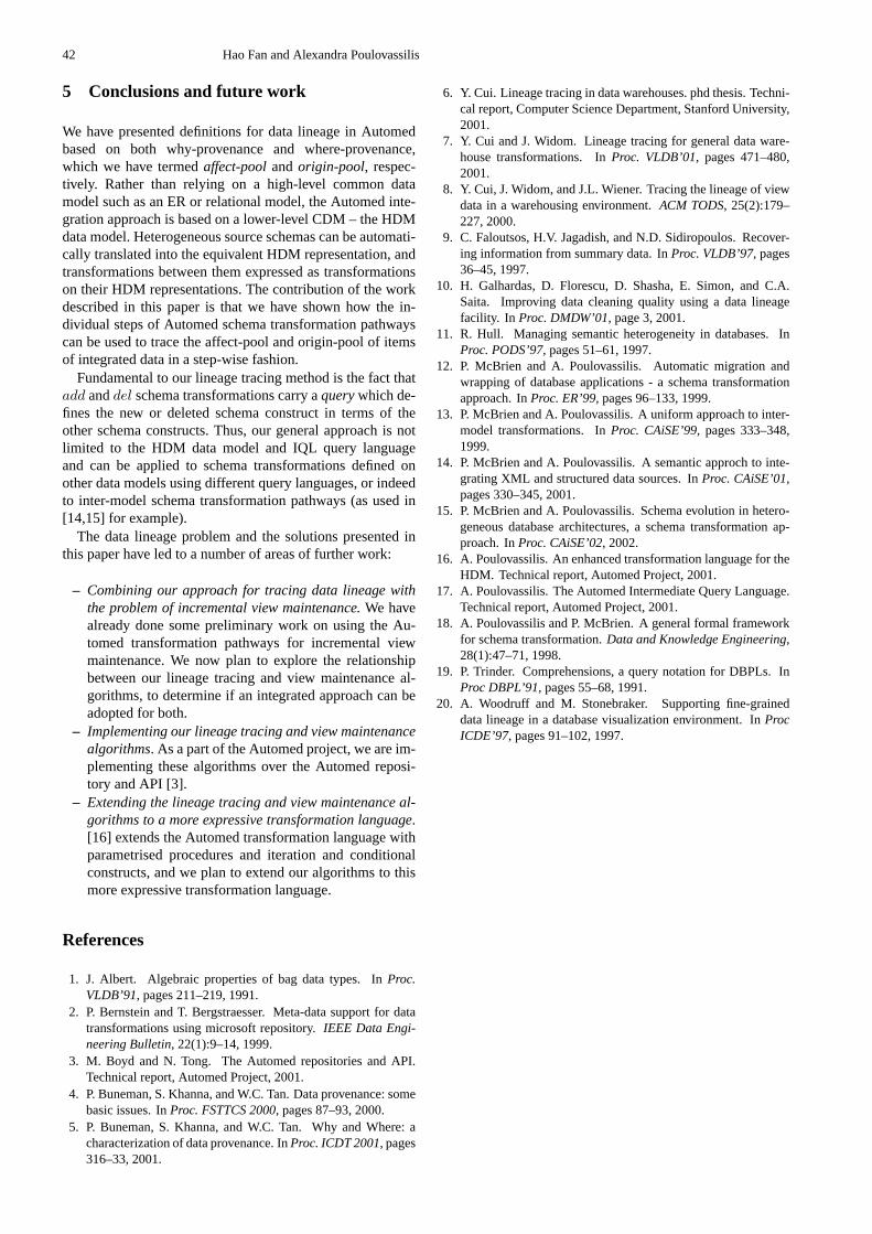
42 Hao Fan and Alexandra Poulovassilis
5 Conclusions and future work
We have presented definitions for data lineage in Automedbased on both why-provenance and where-provenance,which we have termedaffect-poolandorigin-pool, respec-tively. Rather than relying on a high-level common datamodel such as an ER or relational model, the Automed inte-gration approach is based on a lower-level CDM – the HDMdata model. Heterogeneous source schemas can be automati-cally translated into the equivalent HDM representation, andtransformations between them expressed as transformationson their HDM representations. The contribution of the workdescribed in this paper is that we have shown how the in-dividual steps of Automed schema transformation pathwayscan be used to trace the affect-pool and origin-pool of itemsof integrated data in a step-wise fashion.
Fundamental to our lineage tracing method is the fact thatadd anddel schema transformations carry aquerywhich de-fines the new or deleted schema construct in terms of theother schema constructs. Thus, our general approach is notlimited to the HDM data model and IQL query languageand can be applied to schema transformations defined onother data models using different query languages, or indeedto inter-model schema transformation pathways (as used in[14,15] for example).
The data lineage problem and the solutions presented inthis paper have led to a number of areas of further work:
– Combining our approach for tracing data lineage withthe problem of incremental view maintenance.We havealready done some preliminary work on using the Au-tomed transformation pathways for incremental viewmaintenance. We now plan to explore the relationshipbetween our lineage tracing and view maintenance al-gorithms, to determine if an integrated approach can beadopted for both.
– Implementing our lineage tracing and view maintenancealgorithms. As a part of the Automed project, we are im-plementing these algorithms over the Automed reposi-tory and API [3].
– Extending the lineage tracing and view maintenance al-gorithms to a more expressive transformation language.[16] extends the Automed transformation language withparametrised procedures and iteration and conditionalconstructs, and we plan to extend our algorithms to thismore expressive transformation language.
References
1. J. Albert. Algebraic properties of bag data types. InProc.VLDB’91, pages 211–219, 1991.
2. P. Bernstein and T. Bergstraesser. Meta-data support for datatransformations using microsoft repository.IEEE Data Engi-neering Bulletin, 22(1):9–14, 1999.
3. M. Boyd and N. Tong. The Automed repositories and API.Technical report, Automed Project, 2001.
4. P. Buneman, S. Khanna, and W.C. Tan. Data provenance: somebasic issues. InProc. FSTTCS 2000, pages 87–93, 2000.
5. P. Buneman, S. Khanna, and W.C. Tan. Why and Where: acharacterization of data provenance. InProc. ICDT 2001, pages316–33, 2001.
6. Y. Cui. Lineage tracing in data warehouses. phd thesis. Techni-cal report, Computer Science Department, Stanford University,2001.
7. Y. Cui and J. Widom. Lineage tracing for general data ware-house transformations. InProc. VLDB’01, pages 471–480,2001.
8. Y. Cui, J. Widom, and J.L. Wiener. Tracing the lineage of viewdata in a warehousing environment.ACM TODS, 25(2):179–227, 2000.
9. C. Faloutsos, H.V. Jagadish, and N.D. Sidiropoulos. Recover-ing information from summary data. InProc. VLDB’97, pages36–45, 1997.
10. H. Galhardas, D. Florescu, D. Shasha, E. Simon, and C.A.Saita. Improving data cleaning quality using a data lineagefacility. In Proc. DMDW’01, page 3, 2001.
11. R. Hull. Managing semantic heterogeneity in databases. InProc. PODS’97, pages 51–61, 1997.
12. P. McBrien and A. Poulovassilis. Automatic migration andwrapping of database applications - a schema transformationapproach. InProc. ER’99, pages 96–133, 1999.
13. P. McBrien and A. Poulovassilis. A uniform approach to inter-model transformations. InProc. CAiSE’99, pages 333–348,1999.
14. P. McBrien and A. Poulovassilis. A semantic approch to inte-grating XML and structured data sources. InProc. CAiSE’01,pages 330–345, 2001.
15. P. McBrien and A. Poulovassilis. Schema evolution in hetero-geneous database architectures, a schema transformation ap-proach. InProc. CAiSE’02, 2002.
16. A. Poulovassilis. An enhanced transformation language for theHDM. Technical report, Automed Project, 2001.
17. A. Poulovassilis. The Automed Intermediate Query Language.Technical report, Automed Project, 2001.
18. A. Poulovassilis and P. McBrien. A general formal frameworkfor schema transformation.Data and Knowledge Engineering,28(1):47–71, 1998.
19. P. Trinder. Comprehensions, a query notation for DBPLs. InProc DBPL’91, pages 55–68, 1991.
20. A. Woodruff and M. Stonebraker. Supporting fine-graineddata lineage in a database visualization environment. InProcICDE’97, pages 91–102, 1997.

An Algebra for the Composition of Ontologies?
Prasenjit Mitra and Gio Wiederhold
Infolab, Stanford University, Stanford, CA 94305, USA{mitra, gio }@db.stanford.edu
Abstract. Information needs to be composed frommultiple sources to create new information. Suchcomposition is essential, for example, to answerqueries posed by end-users on websites enablingelectronic commerce. In order to facilitate the com-position of information, ontologies have been usedto explicitly define the vocabulary used in the infor-mation sources. Today, a large number of such on-tologies are available. These ontologies in turn aresemantically heterogeneous and the need arises toalign and compose them before we can compose in-formation from the sources. In this paper, we out-line an algebra for the composition of ontologiesand show the properties of the algebraic operators.We show how the articulation generation functiondetermines the properties of the operators and dis-cuss the conditions that these functions must satisfyto enable optimized composition of ontologies.
1 Introduction
Often, queries cannot be answered from information ob-tained from one information source but need information tobe composed from multiple sources. Composing informationfrom multiple information sources creates new and usefulinformation. Thus, in a distributed framework like today’sWorld-Wide Web, it is absolutely crucial for us to composeinformation from multiple sources.
Several approaches to integrate information from diverseinformation sources have been proposed and implementedwith varying success [1], [2], [3], [4] etc.. However, a ma-jor problem to integrating information from various sourcesare the heterogeneity in their vocabularies. In order to solvethis problem, ontologies are increasingly being used to ex-plicitly define the terms and relationships used in an infor-mation source. Since the ontologies themselves are indepen-dently created, we need to resolve the semantic heterogeneityamong them. Thus, before we can compose information frominformation sources, there arises a need to compose their cor-responding ontologies [5]. Ontology-based integration of in-formation has been widely proposed.
In this work, we propose an algebra to enable systematiccomposition of ontologies. Composition of ontologies canthen be expressed in terms of expressions using the ontolo-gies and operators from the algebra. The properties of thealgebraic operators determine the types of optimization thatcan be enabled while composing the ontologies. We describethe properties of the composition operations formally anddiscuss how they can be used to optimize the compositionprocess.
To resolve semantic heterogeneity among ontologies be-fore composing them, we assume that there exists functions? This work has been supported by the AFOSR New World Vistas
program and the DARPA DAML program.
that take in two ontologies and generatearticulation rulesamong them. An articulation rule establishes the correspon-dence between two (or more) terms belonging to the differentontologies that are being articulated. Functions that gener-ate articulation rules are calledarticulation generation func-tions. Articulation rules generated by the articulation gener-ation function form the basis for the composition of ontolo-gies.
The binary operators of the algebra depend upon the artic-ulation rules generated by the articulation generation func-tion. For example, to compute the intersection of two ontolo-gies we need to know which concept in one ontology is simi-lar to which concepts in the other. Not surprisingly, therefore,the properties of the algebraic operators are determined bythe articulation generation functions. Most articulation gen-eration functions are manually written or semi-automaticallygenerated using heuristic methods that try to match two on-tologies and generate their articulation.
In this paper, we discuss the conditions the articulationgeneration functions should satisfy so that the composition ofthe ontologies can be optimized. Even though a lot of workhas been done on suggesting heuristics for articulating andaligning ontologies (or mapping schemas) [6], [7], [8], [9],[10], to the best of our knowledge, no prior work has studiedthe properties of such heuristics and shown how the task ofcomposition of ontologies (or databases) is affected by theirproperties.
The rest of the paper is organized as follows. In the nextsection, we discuss some preliminaries. In Section 3, we de-scribe the algebra and its operators. In Section 4, we discussthe properties of the operators and in Section 5, we conclude.
2 Preliminaries
2.1 Ontologies
The term ”ontology” has many definitions[11],[12]. It hasbeen represented using various data formats and rule lan-guages. Our approach is to use a definition and data for-mat that is simple - a ”least common format”. The for-mat captures the basic features common to most machine-represented ontologies and is simple enough to allow easytransformations from various other ontology formats to ours.
In its core, we represent an ontology as a graph and a setof horn-clause rules. Formally, an ontologyO = (G,R) isrepresented as a directed labeled graphG and a set of rulesR. The graphG = (V,E) comprises a finite set of nodesVand a finite set of edgesE. The label of a node inV is givenby a non-null string. In the context of ontologies, the label isoften a noun-phrase that represents a concept.
The label of an edge inE is the name of a semantic rela-tionship among the concepts inV and can be “null” if the re-lationship is not known. An edge is expressed as aStatement

44 Prasenjit Mitra et al.
of the form(SubjectRObject), whereSubject, Object ∈V andR is therelationshipbetween them.
The semantics of the relationships are typically specifiedin the document it is defined in and the namespace of therelationship is tagged along to clarify the relationship weare referring to. For example,rdfs : subClassOf whererdfs is an alias ofhttp : //www.w3.org/2000/01/rdf −schema# indicates that the relationship that is being used is”subclassOf” as specified in therdfs document. In the restof the paper, we omit the namespace unless we need to dif-ferentiate between two relationships of the same name or weneed to mention the source of the relationship to make ourpoint.
Rules in an ontology are expressed in a logic-based lan-guage. Although, theoretically, it might make sense to usefirst-order logic as the rule language due to its greater expres-sive power, in order to limit the computational complexity wewill use a simpler language like Horn Clauses. A typical ruler ∈ R is of the form :
CompoundStatement⇒ Statement
A Statementis of the form(Subject R Object). SubjectandObject are either labels of node in the ontology graphor a variable that can be bound to one or more nodes inthe ontology graph. As in an edge, the relationshipR ex-presses a relationship between the two conceptsSubject andObject. The antecedent of the ruleCompoundStatementis either a Boolean value (true or false) or a conjunctionof Statements. If the antecedent of the rule istrue, wesimplify the notation by dropping the body of the rule andwriting the consequent as a statement that holds (like edges).Edges can be thought of as rules whose antecedent is alwaystrue. Minimally we could define an ontology as a set of con-cepts and rules (since edges can be expressed as rules), how-ever, we believe the graphical representation aligns with hu-man intuition much better and thus describe our work usingthe above definition. A more detailed description of the on-tology format can be found in [13].
For ease of description of the algebra,we will introduce the following terminology:For a statements = (Subject R Object), Nodes(s)contains Subject(Object) provided Subject(Object)is not a variable ( that is, it is a node in some on-tology graph). For an ontologyO1, Nodes(O1)represents the set of nodes consisting of eachnode that belongs to the ontology graph forO1.For a set of rulesR, Nodes(R) represents the unionof Nodes(s) for all s, such thats is a statement in any ruler ∈ R.
Example 1.We introduce a running example in Figure 1,which we will use throughout the paper.O1, O2, andO3are three ontologies. We only show selected portions of theontology graphs corresponding to the three ontologies. Inorder to specify which ontology a concept is defined in,we tag the name of the ontology it belongs to the name ofthe node. For example, the node labeledO2.Car refers theconceptCar as defined in the ontologyO2. However, wherethe origin of the definition is not important (or is obvious)to the topic of discussion, we will simply use the conceptname without mentioning the fully qualified name (that is,
Car HouseBoat
MSRP
Denomination
Dollar
O2
hasA
hasA
InstanceOf
Boat Automobile
RetailPrice
Denomination
Dollar
O3
hasA
hasA
InstanceOf
LuxuryCarSubClassOf
VehicleO1
Articulation Rules:
true => (O2.Car SubClassOf O1.Vehicle)
(X InstanceOf O1.Car),(X hasA X.MSRP),(Y InstanceOf X.MSRP),
(Y hasA Y.Value), (Z InstanceOf Y.Value), (Y.Value > 40,000)
=> (X InstanceOf O2.LuxuryCar)
Value
hasA
Value
hasA
hasA
SubClassOf
SubClassOf
Fig. 1.Ontologies and Articulation Rules
drop the ontology name tagged in front of it). Let the setR = {(O2.Car SubClassOf O1.V ehicle),(O2.HouseBoat SubClassOf O1.V ehicle)}, thenNodes(R) = {O2.Car,O1.V ehicle,O2.HouseBoat}.
Edges(E,n), whereE is a set of edges andn is a nodein an ontology graph, represents all edges inE incident uponor incident from the noden. Formally,Edges(E,n) = {s ∈E| ∃n′, l : s = (n, l, n′) or s = (n′, l, n)}. Edges(E,N),whereN andE are a set of nodes and edges respectivelyin an ontology graph, represents a set of edgesS ∈ E.Both nodes (the node from which an edge is incident fromand the node to which it is incident upon) of each edgein the setS must belong to the set of nodesN . Formally,Edges(E,N) = s = (n1, l, n2) ∈ E|n1, n2 ∈ N .
2.2 Articulation Rules and Articulation GenerationFunctions
To resolve heterogeneity among ontologies, we need a pro-cedure to generate the correspondences and relationshipsamong concepts in the ontologies. Such relationships arecoded as articulation rules. We call such procedures that gen-erate articulation rules between ontologiesarticulation gen-eration functions. Note that the articulation generation func-tion can be an automatic subroutine that takes in the two on-tologies and outputs the articulation rules or it could be amanual effort where a human expert identifies the articula-tion rules by inspecting the two ontologies or a hybrid semi-automatic strategy that involves both a component that auto-matically suggests articulations and a human component thatratifies them. An articulation generation function takes is twoontologies (domain: the set of all possible ontologiesO) andoutputs a subset of the set of all possible rules (range: the setof all possible rulesR) between them (f : OxO → 2R. Weexpect the articulation generation to be a complete function.That is, given any two ontologies, the function always termi-nates and outputs a set of articulation rules that link them. Anarticulation ruler articulating two ontologiesO1 andO2 issuch that∃O1.n ∈ Nodes(r) and∃O2.n′ ∈ Nodes(r) forsome nodesn andn′ in O1 andO2 respectively.
Example 2.In our running example, we show a few of the ar-ticulation rules generated by an articulation generation func-tion. For lack of space, all articulation rules are not shown in
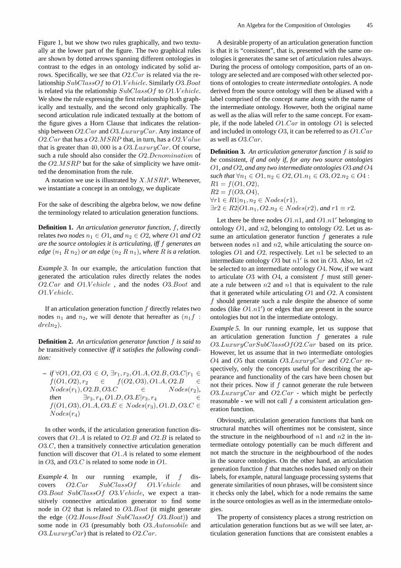
An Algebra for the Composition of Ontologies 45
Figure 1, but we show two rules graphically, and two textu-ally at the lower part of the figure. The two graphical rulesare shown by dotted arrows spanning different ontologies incontrast to the edges in an ontology indicated by solid ar-rows. Specifically, we see thatO2.Car is related via the re-lationshipSubClassOf toO1.V ehicle. SimilarlyO3.Boatis related via the relationshipSubClassOf to O1.V ehicle.We show the rule expressing the first relationship both graph-ically and textually, and the second only graphically. Thesecond articulation rule indicated textually at the bottom ofthe figure gives a Horn Clause that indicates the relation-ship betweenO2.Car andO3.LuxuryCar. Any instance ofO2.Car that has aO2.MSRP that, in turn, has aO2.V aluethat is greater than40, 000 is aO3.LuxuryCar. Of course,such a rule should also consider theO2.Denomination oftheO2.MSRP but for the sake of simplicity we have omit-ted the denomination from the rule.
A notation we use is illustrated byX.MSRP . Whenever,we instantiate a concept in an ontology, we duplicate
For the sake of describing the algebra below, we now definethe terminology related to articulation generation functions.
Definition 1. An articulation generator function,f , directlyrelatestwo nodesn1 ∈ O1, andn2 ∈ O2, whereO1 andO2are the source ontologies it is articulating, ifff generates anedge(n1 R n2) or an edge(n2 R n1), whereR is a relation.
Example 3.In our example, the articulation function thatgenerated the articulation rules directly relates the nodesO2.Car and O1.V ehicle , and the nodesO3.Boat andO1.V ehicle.
If an articulation generation functionf directly relates twonodesn1 andn2, we will denote that hereafter as(n1f :dreln2).
Definition 2. An articulation generator functionf is said tobe transitively connectiveiff it satisfies the following condi-tion:
– if ∀O1, O2, O3 ∈ O, ∃r1, r2, O1.A,O2.B,O3.C|r1 ∈f(O1, O2), r2 ∈ f(O2, O3), O1.A,O2.B ∈Nodes(r1), O2.B,O3.C ∈ Nodes(r2),then ∃r3, r4, O1.D,O3.E|r3, r4 ∈f(O1, O3), O1.A,O3.E ∈ Nodes(r3), O1.D,O3.C ∈Nodes(r4)
In other words, if the articulation generation function dis-covers thatO1.A is related toO2.B andO2.B is related toO3.C, then a transitively connective articulation generationfunction will discover thatO1.A is related to some elementin O3, andO3.C is related to some node inO1.
Example 4.In our running example, if f dis-covers O2.Car SubClassOf O1.V ehicle andO3.Boat SubClassOf O3.V ehicle, we expect a tran-sitively connective articulation generator to find somenode inO2 that is related toO3.Boat (it might generatethe edge(O2.HouseBoat SubClassOf O3.Boat)) andsome node inO3 (presumably bothO3.Automobile andO3.LuxuryCar) that is related toO2.Car.
A desirable property of an articulation generation functionis that it is “consistent”, that is, presented with the same on-tologies it generates the same set of articulation rules always.During the process of ontology composition, parts of an on-tology are selected and are composed with other selected por-tions of ontologies to createintermediate ontologies. A nodederived from the source ontology will then be aliased with alabel comprised of the concept name along with the name ofthe intermediate ontology. However, both the original nameas well as the alias will refer to the same concept. For exam-ple, if the node labeledO1.Car in ontologyO1 is selectedand included in ontologyO3, it can be referred to asO1.Caras well asO3.Car.
Definition 3. An articulation generator functionf is said tobe consistent, if and only if, for any two source ontologiesO1, andO2, and any two intermediate ontologiesO3 andO4such that∀n1 ∈ O1, n2 ∈ O2, O1.n1 ∈ O3, O2.n2 ∈ O4 :R1 = f(O1, O2),R2 = f(O3, O4),∀r1 ∈ R1|n1, n2 ∈ Nodes(r1),∃r2 ∈ R2|O1.n1, O2.n2 ∈ Nodes(r2), andr1 ≡ r2.
Let there be three nodesO1.n1, andO1.n1′ belonging toontologyO1, andn2, belonging to ontologyO2. Let us as-sume an articulation generator functionf generates a rulebetween nodesn1 andn2, while articulating the source on-tologiesO1 andO2. respectively. Letn1 be selected to anintermediate ontologyO3 butn1′ is not inO3. Also, letn2be selected to an intermediate ontologyO4. Now, if we wantto articulateO3 with O4, a consistentf must still gener-ate a rule betweenn2 andn1 that is equivalent to the rulethat it generated while articulatingO1 andO2. A consistentf should generate such a rule despite the absence of somenodes (likeO1.n1′) or edges that are present in the sourceontologies but not in the intermediate ontology.
Example 5.In our running example, let us suppose thatan articulation generation functionf generates a ruleO3.LuxuryCarSubClassOfO2.Car based on its price.However, let us assume that in two intermediate ontologiesO4 andO5 that containO3.LuxuryCar andO2.Car re-spectively, only the concepts useful for describing the ap-pearance and functionality of the cars have been chosen butnot their prices. Now iff cannot generate the rule betweenO3.LuxuryCar andO2.Car - which might be perfectlyreasonable - we will not callf a consistent articulation gen-eration function.
Obviously, articulation generation functions that bank onstructural matches will oftentimes not be consistent, sincethe structure in the neighbourhood ofn1 andn2 in the in-termediate ontology potentially can be much different andnot match the structure in the neighbourhood of the nodesin the source ontologies. On the other hand, an articulationgeneration functionf that matches nodes based only on theirlabels, for example, natural language processing systems thatgenerate similarities of noun phrases, will be consistent sinceit checks only the label, which for a node remains the samein the source ontologies as well as in the intermediate ontolo-gies.
The property of consistency places a strong restriction onarticulation generation functions but as we will see later, ar-ticulation generation functions that are consistent enables a

46 Prasenjit Mitra et al.
sequence of two intersections to be associative. Associativityof operators allow us to compose the ontologies in any or-der and the rearrangement of operators can be often used tooptimize the composition process.
In this work, we do not consider articulation rules thatmight introduce new nodes. For example, while articulatingbetweenPoundSterling andGuilders, an articulation gen-eration function might generate an intermediate node calledEuro and then give the relation betweenPoundSterlingand theEuro and that between theGuilder and theEuro.However, the presence of such an intermediate node influ-ences the properties of the algebraic operators. For example,if an articulation generation function generates intermediatenodes, the intersection operation between ontologies can notbe guaranteed to be associative. Thus, we do not considersuch articulation generation functions in this work but it isan interesting problem to handle in future.
If an articulation generation functionf relates two nodesin two different ontologies using at least one intermediatenode, we say thatf indirectly relatesthe two nodes (using theintermediate node). We denote this as(nf : ireln′), wheren, n′ are the two nodes in different ontologies connected bythe articulation generation functionf .
3 The Ontology-Composition Algebra
In order to formalize the task of composing ontologies, wepropose an algebra for the composition of ontologies. If weuse the algebraic framework to systematically compose on-tologies, we can enable optimizations depending upon theproperties of the operators. In this section, we describe theontology-composition algebra and in the next section we dis-cuss properties of its operators.
The algebra has one unary operator:Select, and three bi-nary operations:Intersection, Union, andDifference.
3.1 Unary Operator
Select: The Select operator is useful to select portions of anontology that might be of interest. For example, a person whowants to buy a car and does not care about houseboats, mightwant to select only portions of ontologyO2 that contain ter-minology about cars and cut out the portions that are not re-lated to cars.
Definition 4. The Select operator has two forms:
1. Given an ontologyO = ((N,E), R), and a noden ∈ N ,Select(O,n) = (Gn, Rn) whereGn = (Nn, En) is asubgraph ofG such that for all nodesn′ in Nn, thereexists a path fromn to n′ in G. The setEn = {e =(n1 R n2) ∈ E|n1, n2 ∈ Nn} is such that each edgein En expresses a relationship between nodesn1 andn2
where both nodesn1 andn2 are inNn Similarly,Rn ={r ∈ R|Nodes(r) ⊆ Nn} is the set of rules obtainedfromR containing all rules inO whose concepts are allin Nn.
2. Given an ontologyO = ((N,E), R), and set of nodesV , Select(O, V ) = (G,Rv) whereG = (V,Ev). ThesetEv = {e = (n1 R n2) ∈ E|n1, n2 ∈ V and the setRv = {r ∈ R|Nodes(r) ⊆ V }.
Example 6.In our example, the ontologyO3 contain theedges (O3.LuxuryCar SubClassOf O3.Automobile),and (O3.LuxuryCar hasA O3.RetailPrice).Select(O3, Automobile) would select all nodesreachable from the node O3.Automobile(LuxuryCar,RetailPrice,Denomination, V alue,and Dollar), and the edges between them.Select(O3, {Automobile, LuxuryCar}) wouldon the other hand only select the nodesO3.LuxuryCar,O3.Automobile and the edge(O3.LuxuryCar SubClassOf O3.Automobile).
Note that a ruler in R that does not involve any node inO hasNodes(r) = φ. Such a rule is included in the se-lected ontology since the empty set is a subset ofN . Forexample, a rule expressing the transitivity of the relationshipSubClassOf
(XSubClassOfY ), (Y SubClassOfZ)⇒ (XSubClassOfZ)
contains only variablesX, Y , andZ and no concepts fromany ontology. Such a rule is included in any selected ontologyS since the rule might be useful to reason about the relation-ships and concepts inS.
There is a case that could be made to include inthe results of the select operation edges (and rules)that can be derived using the edges and rules avail-able in the source ontology. For example, let us sup-pose that we had edges(LuxuryCar SubClassOf Car),and (Car SubClassOfV ehicle) in an ontology O.Select(O, {V ehicle, Car}) would select the last edge. Onthe other handSelect(O, V ehicle, LuxuryCar) would in-clude the nodesV ehicle, andLuxuryCar but no edgessince there are no edges between them. We could define Se-lect to add an edge(LuxuryCar SubclassOf V ehicle)if such a relationship could be derived from the ontologyO, for example, using a rule that said that the relationshipSubClassOf is transitive.
Similarly, it is easy to see that we could introduce addi-tional rules over and above the ones that the currentSelectoperation includes in the selected ontology. However, in or-der to generate these derived edges and rules, the ontologycomposition engine would need to interpret the rules of theontology. In order to allow our framework to be applicableto different ontologies with different interpretation seman-tics for rules and because potentially we could derive an infi-nite number of facts in certain scenarios (say with recursiverules), the ontology composition engine does not interpret therules so as to maintain its simplicity.
3.2 Binary Operators
Intersection Each binary operator takes as operands two on-tologies that we want to articulate, and generates an ontologyas a result, using the articulation rules. The articulation rulesare generated by an articulation generation function.
Intersection is the most important and interesting bi-nary operation. The intersection of two ontologiesO1 =((N1, E1), R1), andO2 = ((N2, E2), R2) with respect tothe set of articulation rule generating functionf is:OI1,2 = O1 ∩f O2, whereOI1,2 = (NI,EI,RI),NI = Nodes(f(O1, O2)),

An Algebra for the Composition of Ontologies 47
EI = Edges(E1, NI ∩ N1) + Edges(E2, NI ∩ N2) +Edges(f(O1, O2)) ,andRI = Rules(O1, NI ∩N1) +Rules(O2, NI ∩N2) +f(O1, O2))).The nodes in the intersection ontology are those nodes thatappear in the articulation rules. An edge in the intersectionontology are the edges among the nodes in the intersectionontology that were either present in the source ontologies orhave been output by the articulation generation function asan articulation rule. The rules in the intersection ontology arethe articulation rules that are present in the source ontologythat use only concepts that occur in the intersection ontology.
Note that since we consider each node as an object insteadof the subtree rooted at the node, we will get only the nodein the intersection by virtue of its appearing in an articula-tion rule and not automatically include its attributes or sub-classes. Again, a minimal linkage keeps the intersection on-tologies small and avoids the inclusion of possibly irrelevantconcepts. Inclusion of attributes will be required to definesubclass relationships among nodes in the source ontologiesprecisely.
Each node in the intersection has a label which containsthe URI of the source in which it appears. If the attributesof the object that it represents are required, the application’squery processor has to get that information from the originalsource. Defining the intersection with a minimal outlook re-duces the complexity of the composition task, and the main-tenance costs, which all depend upon the size of the articula-tion.
Union The union OU between two ontologiesO1 = (V 1, E1, R1) and O2 = (V 2, E2, R2) is ex-pressed asOU = O1 ∪AR O2 = (V U,EU,RU ) whereV U = V 1 ∪ V 2 ∪ V I1,2,EU = E1 ∪ E2 ∪ EI1,2,andRU = R1 ∪R2 ∪RU1,2,and whereOI1,2 = O1 ∩AR O2 = (V I1,2, EI1,2, RI1,2) isthe intersection of the two ontologies.
The setV I1,2 is non-null only if the articulation rules donot introduce new nodes. However, even if two nodes in theontologies being articulated have the same label, say,O1.xandO2.x andf indicates that they represent the same con-cept by generating the ruleO1.x Equals O2.x, in the inter-section and the union ontology, we would retain bothO1.xandO2.x and the edge between them instead of collapsingthem into one node. The articulation rules almost always in-dicate relationships between nodes in the two source ontolo-gies and thus introduces new edges ( the setEI1,2) that werenot there in the source ontologies.
Though queries are often posed over the union of severalinformation sources, we expect this operation to be rarelyapplied to entire source ontologies. The union of two sourceontologies is seldom materialized, since our objective is notto integrate source ontologies but to create minimal articula-tions and interoperate based on them. However, we do expectthat larger applications will often have to combine multiplearticulations and here is where the union operation is handy.
Difference The difference between two ontologiesO1 andO2, written asO1 − O2, between two ontologiesO1 =
((V 1, E1), R1) andO2 = ((V 2, E2), R2) is expressed asOD = ((V D,ED), RD), whereV D = V 1 − V I1,2,ED = E1 − EI1,2, andRD = RI − RI1,2, and whereOI1,2 = O1 ∩f O2 = (V I1,2, EI1,2, RI1,2) is the intersec-tion of the two ontologies using the articulation generationfunction f. That is, the difference ontology includes portionsof the first ontology that are not common to the second ontol-ogy. The nodes, edges and rules that are not in the intersec-tion ontology but are present in the first ontology comprisethe difference.
3.3 Properties of the Operators
We defined the operators in the algebra on the basis of the ar-ticulation rules produced by the articulation generating func-tion. Not surprisingly, most of the properties of the binaryoperations are based on the properties of the articulation gen-erating function.
Idempotence Idempotence is a very important property thatshould hold for operations like union and intersection. In-tuitively, we believe that the union (and intersection) of anontology with itself should result in the same ontology.
For the union operation to be idempotent to hold, we re-quireO1 ∪f O1 = O1. Also, letOU = O1 ∪f O1. LetAR = f(O1, O2). From the definition of the union it followsthatNodes(OU) = Nodes(AR). For union to be idempo-tent, we needNodes(OU) = Nodes(O1) = Nodes(AR).That is,f must generate articulation rules involving all nodesin the ontologyO1. This requirement is obvious since we arematching the same ontology to itself and would expect a setof rules to be generated that matches each node to itself.
Although, the nodes inOU andO1 are the same, the for-mer contains more edges and rules by virtue of the defini-tion of theunion operator. The extra edges are self-edgesbetween a node and itself generated byf that are included inthe union ontology.
Since the edges and rules ofOU andO1 are not the same,OU 6= O1, and theUnion operator is not idempotent. Al-though the strict definition of idempotence is not satisfied, weintroduce the concept ofsemantic idempotence. An binaryoperator is semantically idempotent if and only if the resultof the operation on two copies of the same ontology resultsin an ontology from which if we remove all self-edges andself-rules, the resulting ontology is the same as the sourceontology. Recall that self-edges are edges between one nodeand itself and a self-rule is a rule that has only one node (con-cept) in its definition.
Similarly, we can show that the intersection operator is se-mantically idempotent, if and only if, the articulation gener-ation function that generated the articulation rules betweenan ontology and itself generates self-edges and self-rules foreach node in the ontology.
It is easy to see that the difference operator is not idempo-tent but a difference operation using a well-behaved articula-tion generation function should return the empty set.
The semantic idempotence property serves as a sanitycheck to make sure that the articulation generation functionsthat we employ are semantically meaningful and intuitivelycorrect. Although, in order to guarantee that an articulationgeneration function is idempotent, we would have to check

48 Prasenjit Mitra et al.
over the set of all (potentially infinite) ontologies, in practicewe simply check to see that for the purposes of an applica-tion, the articulation generation function is idempotent for allontologies used by the application. That is, though we do notprove the functions to be idempotent, we check to see thatnone of the ontologies that is useful for the application canbe used to prove that the function is not idempotent. Articula-tion generator functions that do not satisfy the above equalityareunsoundand for the purposes of our compositions, we donot use any unsound articulation generator function.
Commutativity Commutativity of operators is another im-portant property. If an operator is commutative, the optimizerthat is generating a plan for the composition of the ontologieshas the freedom to flip the order of the operands if it sees thatan optimization can be achieved by flipping the order.
Theorem 1. The intersection and union operators are com-mutative if and only if the articulation generation function,on which they are based, is commutative.
The proofs of the theorems are not included in this paperfor space considerations but are provided in [14]. However,strict commutativity of the articulation generation functionmight not be achievable or necessary in order to allow theoperands to be swapped.
Consider the example where an articulation generator gen-erates articulation rules
f(O1, O2) = (O1.Car NM.SubClassOf O2.V ehicle)
and
f(O2, O1) = (O2.V ehicle NM.SuperClassOf O1.Car)
where O1, O2 are two ontologies andNM refers tothe namespace where the semantics of the relationshipsSubClassOf and SuperClassOf are defined. Althoughthe articulation generation function is not commutative,the semantic information contained in the articulation rulesare equivalent as long as the relationsSubClassOf andSuperClassOf defined in the namespaceNM are seman-tically similar after we invert their parameters. Thus, if therules obtained by swapping the operands are semanticallyequivalent, we can swap the operands without compromis-ing on the correctness of the result.
To capture this, we define the concept ofsemantic commu-tativity.
Definition 5. An articulation generation function,f , is se-mantically commutativeifff(O1, O2) ⇔ f(O2, O1)∀O1, O2, whereO1, andO2 areontologies.
and the necessary and sufficient condition for intersection tobe semantically commutative is:
Theorem 2. An intersection operator is semantically com-mutative iff the articulation generation function that it usesto derive the articulation rules is semantically commutative.
To determine the semantic commutativity of an articula-tion generation function, we need to prove that for any pairs
of ontologies, the articulation rules produced by the artic-ulation generation function are in fact semantically equiva-lent. Automatically proving an articulation generator com-mutative or semantically commutative might be easy for theSubClassOf andSuperClassOf examples, but is not al-ways feasible. In such cases, the system requires the pro-grammer of the articulation generation function and/or theexpert to indicate whether the function is semantically com-mutative. In the absence of such information, the system con-servatively assumes that the operation is not semanticallycommutative if it cannot prove otherwise.
We have identified the desired properties that a ”well-behaved” articulation generation function should have so thatquery optimization can be enabled. The algebra plays an im-portant part in influencing query rewriting, optimization andsystematic composition of information that forms the basisfor enabling interoperation among information sources.
Associativity If the operators are associative, then the or-der of their execution can be changed and we can optimizethe execution of the query based on available statistics aboutthe size of the ontologies and their intersections. Therefore,associativity is a very desirable property to have for the op-erators.
Example 7.For example, if we need to compute(O1 ∩fO2) ∩f O3 whereO1 andO2 are very large ontologies andO3 = null. The resulting intersection will obviously be null.If the intersection operator with the articulation generatorfwas associative, we could rewrite the above composition asO1∩f (O2∩f O3). If a query planner chose the former planto execute, it would spend a lot of time articulating the firsttwo large ontologies and then articulate it with a null ontol-ogy. On the other hand, if the intersection operator was as-sociative, an intelligent query planner that knows the sizesof the ontologies could opt for the second formula since inthat case we articulate a large ontology with the null ontol-ogy and then articulate a null ontology with the other largeontology. The presence of the null ontology in both articu-lations should make the second plan faster and require lessstorage for intermediate steps.
Intersection We need to show(O1 ∩ARules O2) ∩ARulesO3 = O1 ∩ARules (O2 ∩ARules O3).
Theorem 3. The intersection operator using an articulationgeneration functionf is associative ifff is consistent andtransitively connective.
A stricter form of a transitively connective articulationgenerator is one that is transitive.
Example 8.Consider the exampleO1 = (car, null, null),O2 = (truck, null, null) andO3 = (vehicle, null, null).That is, the three ontologies simply have one node eachand no edges or rules. Letf be an articulation genera-tion function that is not transitively connective. The thearticulation rules betweenO1 and O2 be as follows:f(O1, O2) = null. Articulating this null ontology withO3returns null. Therefore,(O1 ∪f O2) ∪f O3 = null Onthe other hand, let the articulation rulesf(O2, O3) =(O2.T ruck, SubclassOf,O3.V ehicle). Therefore,

An Algebra for the Composition of Ontologies 49
(O2 ∪f O3) = OI1 = ((O2.T ruck,O3.V ehicle),((O2.truck, SubclassOf,O3.V ehicle)), null). Intersect-ingOI with ontologyO1, we have(O1 ∪f (O2 ∪f O3)) =OI2 = ((O1.Car,O3.V ehicle),((O1.Car, SubclassOf,O3.V ehicle)), null). Since OI1andOI2 are not the same, we see that the intersection isnot associative but depends upon the order of the operandontologies.
In a lot of situations in practice, the person wishing to com-pose the two ontologies does not necessarily have a pref-erence in the order in which the ontologies are composed.In such a scenario, the composer might instruct the systemto assume associativity (and thus enable rearranging of theoperands), even though the articulation generation functionis not provably strictly transitively connective (and thus theintersections are not entirely independent upon the order ofthe operands).
Union The Union operation is associative if and only if∀O1,∀O2,∀O3|(O1∪f (O2∪fO3)) = ((O1∪fO2)∪fO3)wheref is the articulation generation function andO1, O2,andO3 are ontologies.
Theorem 4. The Union operation is associative if and onlyif the associated articulation generation functionf is consis-tent.
A consistent articulation generation functionf is a neces-sary and sufficient condition forUnion with respect tof tobe associative.
Difference Difference is not associative under any con-ditions. We need to show thatO1 − (O2 − O3) is notequal to(O1 − O2) − O3. Let O1, O2, O3 contain onlyone node each:n1, n2, andn3 (respectively). Letf generaterulesRule(n1, n2), Rule(n1, n3), Rule(n2, n3) while artic-ulatingO1 andO2,O1 andO2, andO2 andO3 respectively.Using the definition of difference,(O2−O3) is a null ontol-ogy since the only nodes inO2 andO3, namelyn2 andn3 arerelated byf . ThusO1−(O2−O3) = O1. Again(O1−O2)is a null ontology since the only nodes inO1 andO2, namelyn1 andn2 are related byf . Therefore,(O1−O2)−O3 is anull ontology. Thus, difference is not associative.
Associativity and Articulation Generation Functions Itfollows from the necessary and sufficient conditions that theintersection operation is not associative when the generationof the articulation rules is done by a function that bases its de-cision on the context of the nodes. Functions like structuralmatchers depend upon the presence of certain edges betweennodes in an ontology. Now, the process of intersection mightnot copy all edges in the neighbourhood of a node into the in-tersection ontology. Thus, when the intersection ontology iscomposed with another ontology, the same articulation rulesmight not be generated as would have been if the source on-tology was composed with the second ontology.
Therefore, if the articulation generation function dependsupon structural matchers are employed, the optimizationneeds to be disabled unless the matcher is guaranteed to sat-isfy the conditions mentioned above (primarily consistencyand transitive connectiveness).
Articulation generation functions that are based on linguis-tic matchers just look at the words appearing to describe theconcept and thus often satisfy such conditions.
With respect to optimizing compositions of ontologies, weprefer linguistic matchers to structural matchers. However, ifthe structural matchers generate significant semantic matchesthat are necessary for the application, we just have to pay theprice and not optimize the composition process.
Distributivity Similarly, we show that with a consistent ar-ticulation generation function the∪f and the∩f operationsare distributive as stated below. The distributivity property,again, enables the ontology composition engine to rewriteand reorder a composition task to optimize its performance.
Theorem 5. : (O1∪fO2)∩fO3) = (O1∩fO3)∪(O2∩fO3)iff the articulation generation functionf is consistent.
4 Conclusion
In this paper, we propose an algebra for the composition ofontologies. The algebraic operators closely depend upon theproperties of an articulation generation function that gener-ates the rules on which the algebra is based. Optimizationscan be enabled if the operations are commutative and asso-ciative. We identified the necessary and sufficient conditionsthat articulation generation functions need to satisfy beforethe optimizations can be turned on. As an important corol-lary, we find that linguistic matchers are more well behavedthan structural matchers and allow more scope for optimizingthe process of composing ontologies.
References
1. The stanford-ibm manager of multiple information sourceshttp://www-db.stanford.edu/tsimmis/
2. Information integration using Infomasterhttp://infomaster.stanford.edu/infomaster-info.html
3. Kirk, T., Levy, A.Y., Sagiv, Y., Srivastava, D.: The informationmanifold. In Knoblock, C., Levy, A., eds.: Information Gath-ering from Heterogeneous, Distributed Environments, StanfordUniversity, Stanford, California (1995)
4. C. H. Goh, S. E. Madnick, M.D.S.: Semantic interoperabil-ity through context interchange: Representing and reasoningabout data conflicts in heterogeneous and autonomous systemshttp://citeseer.nj.nec.com/191060.html
5. Wiederhold, G.: An algebra for ontology composition. In:Monterey Workshop on Formal Methods. (1994) 56–61
6. Melnik, S., Garcia-Molina, H., Rahm, E.: Similarity flood-ing: A versatile graph matching algorithm and its applicationto schema matching. In: Proceedings of the Twelfth Interna-tional Conference on Data Engineering, San Jose, CA, IEEEComputer Society (2002)
7. Doan, A., Domingos, P., Halevy, A.Y.: Reconciling schemasof disparate data sources: A machine-learning approach. In:SIGMOD 2002. (2001)
8. Madhavan, J., Bernstein, P.A., Rahm, E.: Generic schemamatching with cupid. In: VLDB 2001, Proceedings of 27th In-ternational Conference on Very Large Data Bases, September11-14, 2001, Roma, Italy, Morgan Kaufmann (2001) 49–58
9. Noy, N., Musen, M.: Prompt: Algorithm and tool for automatedontology mergin and alignment. In: Seventh National Confer-ence on Artificial Intelligence (AAAI-2000). (2000)

50 Prasenjit Mitra et al.
10. McGuiness, D., R.Fikes, Rice, J., Wilder., S.: The chimaeraontology environment. In: Seventh National Conference on Ar-tificial Intelligence (AAAI-2000). (2000)
11. Gruber, T.R.: Toward principles for the design of ontologiesused for knowledge sharing. In Guarion, N., ed.: Padua Work-shop on Formal Ontology. (1993)
12. Sowa, J.F.: http://users.bestweb.net/ sowa/ontology (2000)13. Mitra, P., Kersten, M., Wiederhold, G.: A graph-oriented model
for articulation of ontology interdependencies. In: Advances inDatabase Technology- EDBT 2000. Lecture Notes in ComputerScience, 1777, Springer-Verlag (2000) 86–100
14. Mitra, P.: An algebra for semantic interoperation of informationsources, http://www-db.stanford.edu/ prasen9/alg.txt. Techni-cal report, Infolab, Stanford University (2001)

Knowledge Representation and Transformationin Ontology-based Data Integration?
Silvana Castano and Alfio Ferrara
University of MilanoDSI - Via Comelico, 39
20135 Milano, Italy{castano,ferrara }@dsi.unimi.it
Abstract. The vision of the Semantic Web envis-ages the Web enriched with several domain ontolo-gies specifying formal semantics of data for vari-ous intelligent services. The paper describes an on-tology architecture for integration of heterogeneousXML data sources, where information about DTDsand their contents are represented at a semanticlevel by means of a semantic mapping scheme and amediation scheme. In the paper, we first describe in-formation transformation techniques for designingsuch ontology schemes with heterogeneous XMLdata. Then, we present a rule-based approach forautomatic derivation of a DAML+OIL representa-tion of the ontology knowledge, to enable ontologyinteroperability in Semantic Web.
1 Introduction
The vision of the Semantic Web envisages the Web enrichedwith several domain ontologies, which specify formal se-mantics of data, for different intelligent services for infor-mation search, retrieval, and transformation. In this paper,we focus on ontologies for the integration of heterogeneousXML data sources. The advent of the Web and of XMLhas dramatically increased the need for efficient and flexiblemechanisms to provide integrated views over multiple het-erogeneous information sources, and semantic integration ofXML data sources has recently received special attention inthe database community [1,2]. Research in this field is con-cerned with the development of methods and tools for infor-mation integration with respect to existing semantic hetero-geneity and for semantics management to capture the mean-ing of XML data appropriately [3,4].In this paper, we consider our reference architecture of do-main ontology for XML datasource integration [5], whereinformation about DTDs and their contents are represented atthe global level by means of asemantic mapping schemeanda mediation scheme. Design techniques for building the do-main ontology in a semiautomated way have been developedin the framework of theARTEMIS/MOMIS system [6,7,8]. Inthis paper, we first summarize information transformation is-sues in ontology design, for abstracting XML DTDs into ahigh level representation formalism (calledX-formalism[3]),and the schema matching and unification techniques forderiving the semantic mapping scheme and the mediationscheme. Then, we introduce a rule-based approach for therepresentation of the ontology knowledge in the DAML+OIL
? This paper has been partially funded by MIUR COFIN2000 D2Iproject.
ontology language standard proposal [9,10]. In this way, on-tology knowledge can be exported to Semantic Web in a uni-form and standardized way, ensuring ontology interoperabil-ity.The paper is organized as follows. In Section 2, we describethe reference ontology architecture for XML data integration.In Section 3, we describe the reference ontology formalismfor XML datasource integration and the associated ontologydesign techniques. In Section 4, we describe ontology knowl-edge representation in DAML+OIL. In Section 5, we discussrelated work on data integration. Finally, Section 6 presentsconcluding remarks and future work.
2 Ontology-based XML data integration
We consider a Web-based scenario, where XML is the stan-dard adopted for data exchange among different datasourcesin a given domain. We assume that, for each datasource, datato be integrated are described by means of a DTD, the mostcommonly used type description for XML data. In this sce-nario, we follow a semantic approach to information sharingand integration by setting up adomain ontology, organizingknowledge about datasource DTDs and their contents (e.g.,meaning of elements, sub-elements, attributes, inter-schemaproperties), according to asemantic mapping scheme, and amediation scheme. Each scheme constitutes a layer of the on-tology, provides a semantic view of the different datasources,and is organized as a network ofconceptsandlinks.In the semantic mapping scheme network, we have sets(clusters) of semantically related datasource concepts, for-mally represented asX-classesdefined according to theX-formalismwe adopt for abstracting DTDs [3]. In the media-tion scheme network, we have global concepts, formally rep-resented as global X-classes, providing an integrated repre-sentation of underlying datasource concepts. A global con-cept has associatedmapping rulesspecifying how to map thestructure of the global concept to the structure of the data-source concepts in its associated cluster.
Semantic links expresses semantic relationships betweenconcepts at a given layer (intra-layer links) and also betweenconcepts at different layers (inter-layer links). An intra-layerlink expresses an equivalence relationship between similardatasource concepts forming a cluster in the semantic map-ping layer, or a generic semantic relationship between globalconcepts in the mediation scheme layer, or an is-a relation-ship between global concepts in the mediation scheme layer.An inter-layer link expresses the relationship between a clus-ter and the global concept representative of the cluster at themediation scheme layer above.

52 Silvana Castano, Alfio Ferrara
<!ELEMENT TVSCHEDULE (CHANNEL+)><!ATTLIST TVSCHEDULE NAME CDATA #REQUIRED><!ELEMENT CHANNEL (BANNER, DAY+)><!ATTLIST CHANNEL CHAN CDATA #REQUIRED><!ELEMENT BANNER (#PCDATA)><!ELEMENT DAY ((DATE, HOLIDAY) | (DATE, PROGRAMSLOT+))+><!ELEMENT HOLIDAY (#PCDATA)><!ELEMENT DATE (#PCDATA)><!ELEMENT PROGRAMSLOT (TIME, TITLE, DESCRIPTION?)><!ATTLIST PROGRAMSLOT VTR CDATA #IMPLIED><!ELEMENT TIME (#PCDATA)><!ELEMENT TITLE (#PCDATA)><!ATTLIST TITLE RATING CDATA #IMPLIED><!ATTLIST TITLE LANGUAGE CDATA #IMPLIED><!ELEMENT DESCRIPTION (#PCDATA)>
http://videdot.com/project-report.html (a)
<!ELEMENT TVSCHEDULE (DATE, TVSTATION*)><!ELEMENT DATE EMPTY><!ATTLIST DATE day CDATA #REQUIRED
month CDATA #REQUIREDyear CDATA #REQUIRED>
<!ELEMENT TVSTATION (PROGRAMME*)><!ATTLIST TVSTATION name CDATA #REQUIRED
subscription (yes | no) ’no’adult (yes | no) ’no’>
<!ELEMENT PROGRAMME (TIME, TITLE, VIDEOPLUS?, DESCRIPTION?)><!ATTLIST PROGRAMME language (irish | english | french |
german) ’english’genre (general | drama | film |
science | quiz |documentary | sport | chat |politics | comedy | news |soap | music | children) ’general’
subtitles (yes | no) ’yes’signlanguage (yes | no) ’no’repeat (yes | no) ’no’>
<!ELEMENT TIME EMPTY><!ATTLIST TIME hour CDATA #REQUIRED
minute CDATA #REQUIRED><!ELEMENT TITLE (#PCDATA)><!ELEMENT VIDEOPLUS (#PCDATA)><!ELEMENT DESCRIPTION (TEXT?, CLIP?, FEATURES?, FILM?)><!ATTLIST DESCRIPTION rating
(NA | U | PG | 12 | 15 | 18) ’NA’starrating (NA |1 | 2 | 3 | 4 | 5) ’NA’>
<!ELEMENT TEXT (SHORT?, LONG?)><!ELEMENT SHORT (#PCDATA)><!ELEMENT LONG (#PCDATA)><!ELEMENT CLIP (AUDIO*, STILL*, VIDEO*)><!ELEMENT AUDIO (#PCDATA)><!ATTLIST AUDIO source CDATA #REQUIRED><!ELEMENT STILL (#PCDATA)><!ATTLIST STILL source CDATA #REQUIRED><!ELEMENT VIDEO (#PCDATA)><!ATTLIST VIDEO source CDATA #REQUIRED><!ELEMENT FILM (ACTOR*, DIRECTOR?)><!ATTLIST FILM colour (yes | no) ’yes’
year CDATA #REQUIRED><!ELEMENT ACTOR (#PCDATA)><!ELEMENT DIRECTOR (#PCDATA)><!ELEMENT FEATURES (PRESENTER*,GUEST*)><!ELEMENT PRESENTER (#PCDATA)><!ELEMENT GUEST (#PCDATA)>
http://student.cs.ucc.ie/mmedia00/ak1/theWeb.html (b)
Fig. 1. An example of DTDs of two real datasources in the TV en-tertainment domain
The ontology modelling schemes give raise to a semanticsearch space where users can browse on concept networks atdifferent layers through intra-layer semantic links, and moveacross layers through inter-layer links. The ontology supportsalso mediator services for query formulation and processing,to correctly answer a query formulated on the structure ofa global concept. By exploiting the mapping rules, such aquery can be reformulated by the mediator using the spe-cific terminology and structure of each datasource conceptinvolved in the definition of the global concept. Source datacan then be retrieved and merged by the mediator accordingto the global concept structure for presentation to the user.
3 Ontology design
The domain ontology is built according to a bottom-up pro-cess, articulated in the following steps: (1)DTD abstrac-tion, where DTDs associated with datasources are abstractedinto a set of X-classes according to a reference formalismcalled X-formalism; (2)semantic DTD matching, whereX-classes of different DTDs are grouped on the basis of se-mantic mappings established between them; (3)mediation
scheme design, where X-classes belonging to the same clus-ter are abstracted and unified intoglobal X-classes. More-over, mapping rules are defined between global X-classesand the X-classes in the corresponding clusters to map globalX-classes structure onto the structure of original XML data-sources. In this section, we first summarize X-formalism andthen the schema matching and unification techniques for con-structing the domain ontology schemes. A detailed descrip-tion of such techniques can be found in [8,7,3].
3.1 Reference formalism for DTD abstraction
To build the domain ontology, we assume that XML datato be integrated have associated a DTD, the most com-monly used type description for XML documents1. DTDsare abstracted into a set of X-classes according to the X-formalism [3], capable of describing at a high abstractionlevel the contents of a given DTD, by capturing the semanticsof various elements within the DTD through the concepts ofX-class, property, attribute, link, and referenced X-class. InX-formalism, an X-classxc corresponds to an element dec-laration with element content in XML, and is a 6-tuple of theform xc=(nxc, sxc, Pxc, Lxc, Rxc, Axc), where:nxc is theclass name;sxc is the class structure;Pxc is a set, possiblyempty, of properties;Lxc is a set, possibly empty, of links;Rxc is a set, possibly empty, of referenced X-classes (i.e.,X-classes whose name appears insxc); Axc is a set, possi-bly empty, of attributes. A propertyp of an X-class corre-sponds to an element withPCDATA, any , or empty contentin XML, and is a triple of the formp=(np,tp,Ap) wherenpis a name appearing insxc, tp ∈ {PCDATA,empty,any }is the property type, andAp is a set, possibly empty, of at-tributes. An attributea associated with an X-class (propertyor link, respectively) corresponds to an attribute defined inthe attribute list declaration of an element in XML, and isa triple of the forma=(na,ta,ka), wherena is the attributename,ta is the attribute type, andka is the attribute cardi-nality. A link l corresponds to anXLink elementin XML,and is represented as a class name insxc or as an attributeof a property/class in (Pxc ∪ Rxc). A referenced X-classrcorresponds to an element with element content in the struc-ture of a considered DTD, and is an X-class whose nameappears insxc. In the remainder of the paper, the term “fea-ture” is used to denote a property, link, referenced X-class,or attribute of a given X-class. The cardinality symbols usedin the XML DTD syntax are used to derive cardinality con-straints for X-class features. In particular, ‘+’ corresponds tothe cardinality constraint (1,n), ‘*’ to (0,n), and ‘?’ to (0,1),respectively. If no symbol is specified, the cardinality con-straint (1,1) is taken. In the X-formalism representation, anX-class, property, and attribute is represented as a rectangu-lar, oval, and double oval node, respectively. A link is rep-resented as an oval (or rectangular, depending on its type)labeled with the name of the link and connected by a dou-ble directed arc to the appropriate X-class node. There is anarc between two nodes if there is a containment relationshipbetween them. An XML DTD union structure (‘|’) is repre-sented as anor -labeled dashed arc crossing the arcs enter-
1 X-formalism has been recently extended to support other schemadefinition formalisms for XML, such as XML Schemas orDSDs [11].

Knowledge Representation in Data Integration 53
ing the class/property nodes involved in the union. An XMLDTD sequence structure with a cardinality constraint apply-ing to the whole structure is represented as anand -labeledarc crossing the arcs entering the involved X-class/propertynodes. A description of the basic X-formalism concepts andof their graphical representation is shown in Table 1. Finally,
X-formalism Graphical DescriptionConcept representation
X-class Corresponds to an element decla-ration with element content in aDTD.
Property Corresponds to an element withPCDATA, any , or empty contentin a DTD.
Attribute Corresponds to an attribute de-fined in the attribute list declara-tion of an element in a DTD.
Link Corresponds to anXLink elementin a DTD.
ReferencedX-class
Corresponds to an element withelement content in the structure ofa DTD.
Table 1.Basic X-formalism concepts
cardinality constraints associated with properties, links, at-tributes, and referenced X-classes are explicitly represented,if different from (1, 1), as labels attached to arcs;(1, 1) isimplicitly taken as a default.For instance, consider the DTDs illustrated in Figure 1 de-scribing information about two real TV entertainment data-sources. The X-classes of the first DTD areTvSchedule ,Channel , Day, andProgramslot , while the X-classesof the second DTD areTvSchedule , TvStation , Pro-gramme, Description , Film , Features , Text , andClip . The X-formalism graphical representation of the twoDTD is shown in Figure 2 and in Figure 3, respectively.
TvSchedule
Channel
Day
(1, n )
name
chan
Holiday Date
Date
(1, n )
Banner
Programslot vtr
Time Title Description
Rating language
(1, n )
(1, n )
(1, n )
OR
Fig. 2.X-formalism representation of the DTD in Fig. 1 (a)
3.2 Ontology design techniques
Schema matching techniques.The first step in the con-struction of the ontology consists in defining the semanticmapping scheme. This involves the comparison of X-classesof DTDs associated with different datasources to find simi-larities between them. To this purpose,ARTEMIS providesschema matching techniques based on the concept ofaffinityto identify X-classes having a semantic relationship. Affinityevaluation in ARTEMIS exploits a thesaurus of weightedterminological relationships (e.g., synonymy, hyperonymy)expressing inter-schema knowledge characterizing sourceDTDs. In particular, a validated thesaurus (called CommonThesaurus inARTEMIS/MOMIS) is defined containing thefollowing kinds of weighted terminological relationships:i) automatically extracted from WordNet for names ofX-classes and features (basic ontological knowledge); ii)automatically extracted considering X-classes and structure(schema knowledge); iii) manually supplied by the designer(domain knowledge). Terminological relationships captureinterschema knowledge between X-classes of differentDTDs both at the intensional level and at the extensionallevel (i.e., with reference to possible kinds of instanceoverlappings). We represent the thesaurus as a network,where nodes correspond to names (of X-classes and features)and labeled, weighted edges between nodes correspond toterminological relationships. A semantic mapping is estab-lished between X-classes and their features if their nameshave affinity according to the terminological relationshipsin the thesaurus. Two namesn andn′ have affinity if thereexists at least one path between them in the thesaurus andthe strength of the path is greater than or equal to a giventhreshold. The highest the number of attributes, properties,links, and referenced X-classes with affinity, the higher thestrength of the semantic mapping between two X-classes.A hierarchical clustering algorithm is used to find clustersof semantically related X-classes based on the semanticmapping strengths [8]. The interested reader can referto [7,8] for a detailed discussion of affinity-based schemamatching and some experimental results. For instance,with reference to the DTDs in Figures 2 and 3,ARTEMIS
determines three clusters containing X-classes of bothsources: cl1 = {S1.Tvschedule ,S2.TVschedule },cl2 = {S1.Programslot ,S2.Programme }, and cl3 ={S1.Channel ,S2.TVstation }. remaining X-classesare placed in singleton clusters.
Unification techniques.The subsequent step of the ontol-ogy design is the definition of the mediation scheme. Thisis performed through rule-based unification techniques bywhich X-classes belonging to a given cluster are reconciledinto global X-classes. The mediation scheme design pro-cess proceed as follows. In a first phase, we consider clus-ters of X-classes and we define preliminary global X-classesout of them, which constitute the skeleton global conceptsof the mediation scheme. For each global X-class, in thisstage we identify its basic features, namely, attributes, prop-erties, and links. We leave referenced X-classes pending inthis stage, to be fixed after completing this phase of theprocess. The second phase of the mediation scheme designprocess is devoted to revise preliminary global X-classes,to identify their structure and links. Finally, mapping rules

54 Silvana Castano, Alfio Ferrara
PROGRAMME S1.Programslot S2.Programme
ATTRIBUTESLanguage language CDATA #IMPLIED language (irish | english |
french | german) ’english’... ... ...PROPERTIESTime <!ELEMENT TIME (#PCDATA)> <!ELEMENT TIME EMPTY>Genre NULL genre (general | drama | film |
science | quiz | documentary |sport | chat | politics | comedy |news | soap | music | children)’general’
... ... ...REFERENCED X-CLASSESDescription <!ELEMENT DESCRIPTION (#PCDATA)> <!ELEMENT DESCRIPTION (TEXT?,
CLIP?, FEATURES?, FILM?) >
Table 2.Example of mapping table for the global X-classProgramme
Programme
Description
subtitles
repeat
vtr
signlanguage
time
title
videoplus
genre
minute
hour
language
rating
(0,1)
(0,1)
(0,1)
language
Fig. 4.Example of global X-class
between global X-classes and corresponding local X-classesbelonging to the associated cluster are defined. The globalX-class obtained from a singleton cluster coincides with theX-class in the cluster, that is, it has the same name andthe same features. For clusters containing more than oneX-class, the corresponding global X-class is obtained by rec-onciling properties, attributes, and referenced classes of theX-classes belonging to it by applying a set of basicrecon-ciliation rules whose purpose is to unify names, types, andcardinality constraints. Two kinds of features are consid-ered in unifying X-classes of a cluster, namelyhomologousfeatures (i.e., attribute-attribute and property-property) andnon-homologousones (i.e., attribute-property and property-referenced X-class). This is due to the fact that the sameconcept can be represented in different ways in differentDTDs, using XML elements of different kind and complex-ity. The reconciliation procedure first processes homologousfeatures (i.e., attributes, properties, Xlink attributes). Thereconciliation of non-homologous features is postponed tillall homologous features have been reconciled and a medi-ated feature representative of all them has been obtained.A detailed description of the reconciliation rules for medi-ation scheme design is described in [5]. As an example, theglobal X-classProgramme obtained from reconciliation of
X-classes of clustercl2 is shown in Figure 4. To complete theglobal X-class definition,mapping rulesare specified. Foreach global X-class, a persistentmapping-tablestoring allthe mapping rules is generated; it is a table whose columnsrepresent the set of the local X-classes belonging to the clus-ter associated with a given global X-class and whose rowsrepresent the global X-class features. For a given row, eachentry of the table contains the XML syntax of the correspond-ing feature of the involved local X-class in the cluster. An ex-ample of mapping rules for the global X-classProgrammeis shown in Table 2.
4 Ontology knowledge representation
In order to increase ontology interoperability for Seman-tic Web, a RDF and RDFSchema representation of theknowledge in our ontology is required. To this purpose, wedescribe ontology scheme knowledge representation usingDAML+OIL. In particular, we provide a set of rules to auto-matically derive the DAML+OIL description of the ontologysemantic mapping scheme and mediation scheme from theX-formalism formalization.First, we define the basic DAML+OIL concepts for X-formalism. Then, we define the rules for deriving theDAML+OIL representation of X-classes and clusters ofthem. Finally, we define the rules for deriving theDAML+OIL representation of the global X-classes and as-sociated mapping rules.
4.1 Basic concepts definition
The basic ontology concept to be represented in DAML+OILis the X-class, which can be local or global dependingon the scheme layer of the ontology we are considering.An X-class is defined by a name and a structure. TheX-class structure is defined in terms of names of proper-ties and/or names of other referenced X-classes. We de-fine a DAML+OIL classX-class in order to representX-classes and two DAML+OIL subclasses ofX-classnamedLocalX-class and GlobalX-class to repre-sent X-classes in the semantic mapping scheme (namedlocal X-classes in the following) and global X-classes in

Knowledge Representation in Data Integration 55
<daml:Class rdf:ID=LocalX-class><rdfs:subClassOf rdf:resource=#X-class/><rdfs:subClassOf>
<daml:Restriction><daml:onProperty
rdf:resource=#hasProperty/><daml:toClass rdf:resource=#Property/>
</daml:Restriction></rdfs:subClassOf><rdfs:subClassOf>
<daml:Restriction><daml:onProperty rdf:resource=#hasLink/><daml:toClass rdf:resource=#Link/>
</daml:Restriction></rdfs:subClassOf><rdfs:subClassOf>
<daml:Restriction><daml:onProperty
rdf:resource=#hasAttribute/><daml:toClass rdf:resource=#Attribute/>
</daml:Restriction></rdfs:subClassOf><rdfs:subClassOf>
<daml:Restriction><daml:onProperty
rdf:resource=#hasRefX-class/><daml:toClass rdf:resource=#X-class/>
</daml:Restriction></rdfs:subClassOf>
</daml:Class>
Fig. 5.DAML+OIL definition of LocalX-class
the mediation scheme, respectively. Furthermore, we de-fine a DAML+OIL classCluster to represent the clustersof the semantic mapping scheme. We define DAML+OILclassesProperty , Link , and Attribute , to repre-sent properties, links, and attributes of X-classes. Moreover,we define DAML+OIL object propertieshasProperty ,hasLink , hasAttribute , and hasRefX-class torepresent the relationships between X-classes and theirproperties, links, attributes, and referenced X-classes, re-spectively. Attribute, property and link types are repre-sented through the datatype propertiesAttributeType ,PropertyType , andLinkType , respectively. TheAt-tributeType range is the union of the attribute typesallowed in XML, the PropertyType range is the set{PCDATA, any, empty }, and theLinkType range isthe union of the property types and the features of the X-classstructure. Feature cardinalities are represented by the objectproperty card , whose range is the class of the cardinal-ities used in X-formalism, expressed as a pair (mc,MC),wheremc denotes the min cardinality andMC the maxcardinality. As an example, the DAML+OIL definition ofLocalX-class is reported in Figure 5. A summary ofthese basic DAML+OIL concepts is given in Table 3.
4.2 Rules for semantic mapping scheme representation
For each X-classxc of the semantic mapping scheme, aninstance of the DAML+OIL classLocalX-class is de-fined whose structure is derived from attributes, properties,links, and referenced X-classes ofxc applying the following
DAML+OIL concept Description
Classes
X-class Represents the general structure ofX-classes in the ontology schemes.
LocalX-class Represents the structure of theX-classes describing the datasourceconcepts in the semantic mappingscheme.
GlobalX-class Represents the structure of theglobal X-classes describing globalconcepts in the mediation scheme.
Cluster Represents the structure of clustersin the semantic mapping scheme.
Property Represents properties of X-classes.Link Represents links between
X-classes.Attribute Represents attributes of X-classes.
Object properties
hasProperty Represents the relationship be-tween an X-class and its properties.
hasLink Represents the relationship be-tween an X-class and its links.
hasAttribute Represents the relationship be-tween an X-class and its attributes.
hasRefX-class Represents the relationship be-tween an X-class and its referencedX-classes.
card Represents the relationship be-tween each feature X-class and itscardinality.
Datatype properties
AttributeType Represents the attribute types.PropertyType Represents the property types.LinkType Represents the link types.
Table 3.Description of the basic DAML+OIL concepts
X-formalism-to-DAML+OIL translation rules.
Attribute. An attribute a = (na, ta, ka) is translatedinto an instance of the DAML+OIL classAttribute ,namedna. The instance type is the attribute typeta. Theattribute cardinalityka is represented by means of the objectpropertycard in the DAML+OIL class instance defined fora.
Property. A property p = (np, tp, Ap) is translatedinto an instancenp of the DAML+OIL basic classProp-erty . The property typetp is the value of the DAML+OILproperty PropertyType . For each attributeai ∈ Apan object property clausehasAttribute is defined.The target of this property is the DAML+OIL instancerepresentingai. The property cardinality specified in theX-class structure is represented using the object propertycard in the DAML+OIL class instance defined forp.
Link. A link l = (nl, tl) is translated into an instancenl of the DAML+OIL classLink . The link typetl is thevalue of the DAML+OIL propertyLinkType .
Referenced X-class.A referenced X-classr is trans-

56 Silvana Castano, Alfio Ferrara
<LocalX-class rdf:ID=S2.Programme><card>(0,n)</card><hasAttribute rdf:resource=#S2.language/><hasAttribute rdf:resource=#S2.genre/><hasAttribute rdf:resource=#S2.subtitles/><hasAttribute rdf:resource=#S2.repeat/><hasAttribute
rdf:resource=#S2.signlanguage/><hasProperty rdf:resource=#S2.time/><hasProperty rdf:resource=#S2.title/><hasProperty rdf:resource=#S2.videoplus/><hasRefX-class
rdf:resource=#S2.Description/></LocalX-class>
Fig. 6. Example of DAML+OIL specification for the local X-classS2.Programme
lated into an instancenr of the LocalX-class , wherenr is the name ofr. The referenced X-class cardinalityspecified in the X-class structure is represented using theobject propertycard in the DAML+OIL specification forr.
X-class. An X-class xc = (nxc, sxc, Pxc, Lxc, Rxc,Axc) is translated into an instancenxc of the DAML+OILclassLocalX-class . If the X-classxc is a referencedX-class, it is translated according to the referenced X-classtranslation rule. In order to represent the X-class properties,the DAML+OIL object propertyhasProperty is used.Each propertypi ∈ Pxc which satisfieshasProperty hasto belong to the classProperty . According to the sameprocess, the propertieshasLink and hasAttributeare used for each linkli ∈ Lxc, and for each attributeai ∈ Axc. Finally, a propertyhasRefX-class is usedfor each referenced X-classri ∈ Rxc
2. As an example,the DAML+OIL specification of the referenced X-classS2.Programme is shown in Figure 6.
<Cluster rdf:ID= cl2><AffinityValue>0.667</AffinityValue><ClusterMember>
<rdf:bag><rdf:li>S1.Programslot</rdf:li><rdf:li>S2.Programme</rdf:li>
</rdf:bag></ClusterMember>
</Cluster>
Fig. 7.DAML+OIL representation on the clustercl2
Cluster. A cluster is represented as an instance of the classCluster . The instance name is the cluster name, and apropertyAffinityValue is defined in order to representthe affinity value associated with the cluster. Moreover, apropertyClusterMember is defined in order to represent
2 The structuresxc of an X-class is not explicitly represented inDAML+OIL; however it can be easily derived by consideringthe set of DAML+OIL object properties of theLocalX-class
the X-classes composing the cluster. TheClusterMemberdomain is the classCluster , while its range is the classLocalX-class . As an example, the DAML+OIL specifi-cation of the clustercl2 is shown in Figure 7.
4.3 Rules for mediation scheme representation
A global X-class is defined as an X-class plus a setMPof mapping rules, which represent the mappings betweenthe features of the global X-class and the features of theX-classes belonging to the cluster from which the globalX-class has been derived. A global X-class is translatedin DAML+OIL using the rules previously described forthe local X-class translation. An additional rule is nowintroduced for translating mapping rules in DAML+OIL.
Mapping rule. A mapping rule defines for each property,link, attribute, and referenced X-class of a global X-classthe corresponding feature (if any) of each local X-class ofthe involved cluster. We define a basic DAML+OIL objectpropertyMappingRule to represent a mapping rule. Foreach property, link, attribute, and referenced X-class of aglobal X-class, aMappingRule property is specified torepresent the corresponding features in each source X-class.For each MappingRule , a GlobalFeature and aSourceFeature object properties are defined to representthe feature of the global X-class and the correspondingfeatures in local X-classes, by referring to the correspondingDAML+OIL class. If a global feature does not have acorresponding feature in a local X-class of the cluster, (i.e.,aNULLvalue is specified in the mapping table), such a localfeature is not listed in theSourceFeature DAML+OILobject property.
Global X-class.A global X-classgxc is translated into an in-stancengxc of the DAML+OIL classGlobalX-class byapplying the translation rules for X-class and mapping rules.For eachhasProperty , hasLink , hasAttribute ,and hasRefX-class property, aMappingRule prop-erty is specified which links the DAML+OIL class instancerepresenting the global feature with the DAML+OIL classinstance representing the corresponding source feature. InFigure 8, we show an example of DAML+OIL specificationfor the global X-classProgramme of Figure 4, with thesample mapping rules of Table 2.
5 Related work
Work related to the issues discussed in the paper regards in-formation integration. The goal of information integration isto construct a global description, called global schema, of amultitude of heterogeneous datasources, to provide the userwith a uniform query interface against the sources, indepen-dent from their location and from heterogeneity of their data.In the literature, several approaches and tools for the inte-gration of heterogeneous data sources have been developed,and information integration architectures based on media-tor/middleware data models and ontologies have been pro-posed [12,13,14,15]. More recently, approaches and systemshave been proposed specifically devoted to semantic repre-sentation and integration of XML datasources. In the follow-

Knowledge Representation in Data Integration 57
<GlobalX-class rdf:ID=Programme><hasAttribute rdf:resource=#language/><MappingRule>
<GlobalFeature rdf:resource=#language/><SourceFeature>
<rdf:Bag><rdf:li rdf:resource=#S1.language/><rdf:li rdf:resource=#S2.language/>
</rdf:Bag></SourceFeature>
</MappingRule>...<hasProperty rdf:resource=#TIME/><MappingRule>
<GlobalFeature rdf:resource=#TIME/><SourceFeature>
<rdf:Bag><rdf:li rdf:resource=#S1.TIME/><rdf:li rdf:resource=#S2.TIME/>
</rdf:Bag></SourceFeature>
</MappingRule><hasProperty rdf:resource=#GENRE/><MappingRule>
<GlobalFeature rdf:resource=#GENRE/><SourceFeature rdf:resource=#S2.genre/>
</MappingRule>...<hasRefX-class rdf:resource=#Description/><MappingRule>
<GlobalFeature rdf:resource=#Description/><SourceFeature>
<rdf:Bag><rdf:li>S1.DESCRIPTION</rdf:li><rdf:li>S2.DESCRIPTION</rdf:li>
</rdf:Bag></SourceFeature>
</MappingRule>...
</GlobalX-class>
Fig. 8.Example of DAML+OIL specification for the global X-classProgramme of Figure 4
ing, we consider such works by focusing on schema match-ing and integration techniques and on metadata representa-tion issues, which are more strictly related with our work de-scribed in the paper.
Cupid [1] is a schema matching system providing differ-ent matching techniques for discovering mappings betweenelements of heterogeneous schema descriptions. Metadatarepresentation is through through graphs, using an extendedEntity-Relationship model. Cupid computes similarity coef-ficients among elements of different schemas, using a combi-nation of matching techniques. In a linguistic matching stage,a linguistic similarity coefficient is computed between pairsof elements, by considering their name, type and domain. In astructural matching stage, the similarity of the elements con-text is also considered. Finally, the similarity between eachpair of elements is computed as the average of the two simi-larity coefficients obtained in the two phases. In this system,the focus is mainly on schema matching techniques, ratherthan to datasource integration. Our schema matching tech-
niques for XML data, can be performed by taking into ac-count both linguistic and structure information on X-classesby means of X-formalism and of the thesaurus of termino-logical relationships.
In the Xyleme project [2], automated data integration tech-niques are developed for creating a dynamic XML ware-house for the Web. In particular, a DTD classification intodomains is performed based on a statistical analysis of thesimilarities between labels in the considered DTDs. Thesesimilarities are defined using ontologies or thesauri. Then,semantic mappings between elements in different DTDs areidentified. Metadata representation at the global level is pro-vided by the so calledabstract DTDs. An abstract DTD isa unified representation of the DTDs associated with a setof XML documents in a given domain, and is modeled as atree. The proposed solution for defining path mappings usesstandard natural language techniques and a thesaurus, andrelies on human interaction especially for identifying map-pings between DTD paths. Machine-learning techniques forXML datasource integration are described [4], for matchingsource DTDs against a pre-defined global schema in form ofDTD. The system ask the user to provide semantic mappingsfor a small set of datasources. A set of instance matchers,called learners, are trained on such mappings during a pre-processing step, in order to discover instance patterns andmatching rules to be applied for matching new DTDs againstthe global schema. Also in this system, metadata represen-tation is provided by XML schema trees. This system fol-lows a “local-as-view” approach to integration, in that theglobal schema is given and local source schemas are definedas views over the global schema. In our approach, we followa “global-as-view” approach to integration, and we constructthe global schema (i.e., the mediation scheme of our ontolo-gy) following a bottom-up process. The mediation scheme isthen mapped on local schemas, by means of mapping rules.
In [16], a methodological framework for information in-tegration, based on a knowledge representation approach ispresented. The representation of both the sources and theglobal domain is provided by Description Logics. The inte-gration is performed according to a local-as-view approach,and, as such, it is focused on representation of mappingsbetween source schemes and the global schema. The pro-posed approach emphazises the role of Description Logicsfor knowledge representation and reasoning in informationintegration. The DAML+OIL representation described in thispaper can play an analogous role.
Main contributions of our work with respect to these pro-posals regard: i) the organization of the ontology integrationknowledge into a semantic mapping scheme layer and a me-diation scheme layer; ii) the use of X-formalism for repre-senting source DTDs, which allows to conceptually describeDTDs contents and their role following a data model ap-proach (i.e., by distinguishing concepts like X-class, prop-erty, link); iii) use of DAML+OIL for ontology knowledgerepresentation, using a language ensuring compatibility andinteroperability with Semantic Web.
6 Concluding remarks
In this paper, we have described ontology-based integrationof heterogeneous XML data sources, where ontology knowl-

58 Silvana Castano, Alfio Ferrara
edge is organized into a semantic mapping scheme and a me-diation scheme. We have described the ontology design tech-niques, which are schema matching techniques, for derivingclusters of semantically related datasource concepts in the se-mantic mapping scheme, and unification techniques, for de-riving global concepts and links in the mediation scheme.Such techniques rely on the X-formalism conceptual repre-sentation of source DTDs for mapping DTD contents to con-structs of X-class, properties, attributes, links, and referencedX-class and on a thesaurus of terminological relationshipsspecifying interschema knowledge. We have described on-tology knowledge representation with DAML+OIL to exportthe ontology knowledge to Semantic Web in a standardizedway.
Future research work will proceed in the followingdirections. A CORBA module for producing DAML+OILspecification of the ontology is being developed in theframework of the ARTEMIS tool environment. Actually,ARTEMIS implements the ontology using ODLI3 , theODL-based object-oriented integration language developedin MOMIS [7]. In particular, ODLI3 describes heterogeneousschemas of structured and semistructured data sources ina common way and represents the mediation scheme andassociated mapping rules obtained from the integrationprocess by means of the basic construct of ODLI3 class withattributes of predefined or complex type. We are studyinghow to derive the DAML+OIL specification of the ontologyknowledge by considering directly ODLI3 . In this respect,the results presented in this paper will constitute the startingbase for designing the rules for the ODLI3-to-DAML+OILrepresentation. Moreover, the DAML+OIL knowledge rep-resentation can be the basis to export metadata knowledge toa metadata repository. We will address this problem in thecontext of the D2I (Integration, Warehousing, and Miningof Heterogeneous Data Sources) project, where a metadatarepository has been defined, providing a centralized andunified representation of the metadata documenting allactivities related to integration applications. Finally, wewill study how our matching and unification techniques canbe extended to the problem of matching and integratingontologies, by considering DAML+OIL specifications as aninput to the ontology design process.
References
1. Madhavan, J., Bernstein, P., Rahm, E.: Generic schema match-ing with cupid. In: Proc. of the Int. Conf. on Very Large DataBases (VLDB’01), Rome, India (2001) 49–58
2. Reynaud, C., Sirot, J., Vodislav, D.: Semantic integrationof XML heterogeneous data sources. In: Proc. of the Inter-national Database Engineering and Applications Symposium(IDEAS’01), Grenoble, France (2001) 199–208
3. Castano, S., Antonellis, V.D., di Vimercati, S.D.C.: An XML-based interorganizational knowledge mediation scheme to sup-port B2B solutions. In: 9th IFIP 2.6 Working Conference onDatabase Sematics (DS-9), Hong Kong, China (2001)
4. Doan, A., Domingos, P., Halevy, A.: Reconciling schemasof disparate data sources: A machine-learning approach. In:Proc. of ACM SIGMOD 2001, Santa Barbara, California, USA(2001) 509–520
5. Castano, S., Antonellis, V.D., Ferrara, A., Ottathycal, G.K.: Adisciplined approach for the integration of heterogeneous XMLdatasources. In: Proc. of DEXA WEBS Workshop, Aix-en-Provence, France (2002) To appear.
6. The ARTEMIS project http://www.ing.unibs.it/∼deantone/ in-terdatatema3/Artemis/artemis.html.
7. Bergamaschi, S., Castano, S., Vincini, M., neventa no, D.B.:Semantic integration of heterogeneous information sources.Data and Knowledge Engineering36 (2001)
8. Castano, S., Antonellis, V.D., di Vimercati, S.D.C.: Globalviewing of heterogeneous data sources. IEEE Transactions onKnowledge and Data Engineering13 (2001)
9. Connolly, D., van Harmelen, F., Horrocks, I., McGuinness,D., Patel-Schneider, P., Stein, L.: DAML+OIL (March 2001)Reference Description http://www.w3.org/TR/2001/NOTE-daml+oil-reference-20011218.
10. Horrocks, I.: DAML+OIL: a reason-able web ontology lan-guage. In: Proc. of EDBT 2002. (2002)
11. Castano, S., Antonellis, V.D., di Vimercati, S.D.C., Melchiori,M.: Semi-automated extraction of ontological knowledge fromXML datasources. In: Proc. of DEXA WEBH Workshop, Aix-en-Provence, France (2002) To appear.
12. Fernandez, M., Florescu, D., Kang, J., Levy, A., Suciu, D.:Catching the boat with strudel: Experiences with a web-sitemanagement system. In: Proc. of ACM SIGMOD Interna-tional Conference on Management of Data, Seattle, Washing-ton, USA (1998) 414–425
13. Garcia-Molina, H., Papakonstantinou, Y., Quass, D., Rajara-man, A., Sagiv, Y., et al., J.U.: The tsimmis approach to medi-ation: Data models and languages. Journal of Intelligent Infor-mation Systems2 (1997) 117–132
14. Haas, L., Miller, R., Niswonger, B., Roth, M., Schwarz, P.,Wimmers, E.: Transforming heterogeneous data with databasemiddleware: Beyond integration. IEEE Data Engineering Bul-letin 1 (1999) 31–36
15. Levy, A., Rajaraman, A., Ordille, J.: Querying heterogeneousinformation sources using source descriptions. In: Proc. of the22nd Int. Conf. on Very Large Data Bases (VLDB’96), Mum-bay (Bombay), India (1996) 251–262
16. Calvanese, D., Giacomo, G.D., Lenzerini, M., Nardi, D.,Rosati, R.: Knowledge representation approach to informationintegration. In: Proc. of AAAI Workshop on AI and Informa-tion Integration, AAAI Press/The MIT Press (1998) 58–65

Knowledge Representation in Data Integration 59
TvSchedule
TvStation
Programme
Description
Film Features Text Clip
date day
year
month
name
subscription
adult language
subtitles
genre
repeat
time
title
videoplus signlanguage
hour
minute
colour
year
director actor presenter guest
short
long audio
still
video
source source
source
(0, n )
(0, n )
(0, n ) (0, n ) (0, n ) (0, n ) (0, n ) (0, n )
(0, n )
(0,1)
(0,1)
(0,1) (0,1) (0,1) (0,1)
rating
starrating
(0,1)
(0,1)
Fig. 3.X-formalism representation of the DTD in Fig. 1 (b)

MAFRA — A MApping FRAmework for Distributed Ontologiesin the Semantic Web
Alexander Maedche1, Boris Motik1, Nuno Silva12, and Raphael Volz1
1 FZI Research Center for Information Technologies at the University of Karlsruhe, D-76131 Karlsruhe, Germany{maedche,motik,silva,volz }@fzi.de
2 ISEP Instituto Superior de Engenharia, Instituto Politecnico do Porto, Portugal
Abstract. Ontologies as means for conceptualiz-ing and structuring domain knowledge within acommunity of interest are seen as a key to realizethe Semantic Web vision. However, the decentral-ized nature of the Web makes achieving this con-sensus across communities difficult, thus, hamper-ing efficient knowledge sharing between them. Inorder to balance the autonomy of each communitywith the need for interoperability, mapping mech-anisms between distributed ontologies in the Se-mantic Web are required. In this paper we presentMAFRA, an interactive, incremental and dynamicframework for mapping distributed ontologies inthe Semantic Web.
1 Introduction
The current WWW is a grea1t success with respect to theamount of stored documents and the number of users. How-ever, the ever-increasing amount information on the Webplaces a heavy burden of accessing, extracting, interpretingand maintaining information on the human users of Web. TimBerners-Lee, the inventor of the WWW, coined the vision ofSemantic Web, providing means for annotation of Web re-sources with machine-processable metadata providing themwith background knowledge and meaning (see [2]). Ontolo-gies as means for conceptualizing and structuring domainknowledge are seen as the key to enabling the fulfillment ofthe Semantic Web vision.
However, the de-centralized nature of the Web makes in-deed inevitable that communities will use their own ontolo-gies to describe their data. In this vision, ontologies are them-selves distributed and the key point is the mediation be-tween distributed data using mappings between ontologies.Thus, complex mappings and reasoning about those map-pings are necessary for comparing and combining ontolo-gies, and for integrating data described using different on-tologies [15]. Existing information integration systems andapproaches (e.g., TSIMMIS [6], Information Manifold [8],Infomaster3, MOMIS4, Xyleme5) are “centralized” systemsof mediation between users and distributed data sources,which exploit mappings between a single mediated schemaand schemas of data sources. Those mappings are typicallymodeled as views (over the mediated schema in the local-as-view approach, or over the sources schemas in the global-as-view approach) which are expressed using languages havinga formal semantics. For scaling up to the Web, the “central-
3 http://infomaster.stanford.edu/infomaster-info.html4 http://sparc20.ing.unimo.it/Momis/5 http://www.xyleme.com
ized” approach of mediation is probably not flexible enough,and distributed systems of mediation are more appropriate.
Building on this idea and on existing work, we introducein this paper MAFRA, an Ontology MApping FRAmework(MAFRA) for distributed ontologies in the Semantic Web.Within MAFRA we provide an approach and conceptualframework that provides a generic view onto the overall dis-tributed mapping process. The distributed nature of SemanticWeb entails significant degrees of information redundancy,incoherence and constant evolution, thus changing the natureof the ontology mapping problem: instead of creating a staticspecification document relating entities in two ontologies, acontinuous, incremental, interactive and highly dynamic pro-cess supporting mapping evolution is required to scale up tothe ever-changing nature of ontologies being mapped. Estab-lishing a mapping between two ontologies is an engineeringprocess of consensus building between two communities al-ready agreeing on common ontologies for their own respec-tive domains. This task implies negotiation, so attention ispaid to providing means for cooperative mapping. Thus, pro-posed framework offers support in all parts of the ontologymapping life-cycle.
Organization of this paper.In section 2 we motivate ourwork by introducing an application for whose success a solu-tion to the distributed ontology mapping problem is required.Based on this application, we have collected the requirementsfor developing MAFRA. In section 3 we introduce the un-derlying conceptual architecture of MAFRA. In section 4 wefocus on mapping representation and present the current sta-tus of our semantic bridging ontology and discuss its fea-tures. Section 5 presents the realized mapping implementa-tion within KAON - an ontology and Semantic Web applica-tion framework6. Before we conclude a short discussion ofrelated and future work is given in section 6.
2 MAFRA – Application Scenarios
Design of MAFRA recognizes specific requirements of sev-eral concrete application scenarios. In this section we presentone of these scenarios and discuss its respective require-ments.
“People can’t share knowledge if they do not speak a com-mon language”. This simple insight accurately characterizeswhat makes knowledge management a challenging task. Itsgoal to reach global knowledge access within different de-partments of an enterprise is usually difficult due to the factthat different departments usually encompass different vo-cabularies, which hinders communication. Large companies
6 http://kaon.semanticweb.org

MAFRA — An Ontology MApping FRAmework 61
typically consist of departments such as Human Resources,Production, Sales, Marketing and Finance. By using ontolo-gies, the task of collecting, organizing, and distributing theknowledge within one department may be solved – ontolo-gies provide a sound semantic basis for the definition ofmeaning that can be understood by both humans and ma-chines. Also, a single department is typically small enoughso that achieving consensus among interested parties is fea-sible. However, designing a large-scale ontology covering theneeds of all departments has shown to be a very difficult taskdue to effort, scale and maintainability. Interoperability be-tween departments can then be achieved by mapping of on-tologies of each department. It is anticipated that mappingexisting ontologies will be easier than creating common on-tology because a smaller community is involved in the pro-cess. It is important to emphasize that we do not consider aclosed world and centralized information integration systemas a possible solution for the problem introduced above.
Ontologging7 is an ontology-based environment tacklingthis problem. It builds on Semantic Web standards with thegoal of enabling next generation knowledge management ap-plications allowing management and usage of multiple on-tologies. An important requirement within the developmentof the Ontologging multi-ontology system is that there ex-ists extensive tool support for supporting the overall mappingprocess. A specific requirement was the support of automaticdetection of similarities of entities contained in the two dif-ferent department ontologies.
3 Conceptual Framework
An ontology mapping process, as defined in [14], is the setof activities required to transform instances of a source on-tology into instances of a target ontology. By studying theprocess and analyzing different approaches from the liter-ature [14] we observed a set of commonalities and assem-bled them into the MAFRA conceptual framework, outlinedin Figure 1. The framework consists of five horizontal mod-ules describing the phases that we consider fundamental anddistinct in a mapping process. Four vertical components runalong the entire mapping process, interacting with horizontalmodules.
3.1 Horizontal Dimension of MAFRA
Within the horizontal dimension, we identified following fivemodules:
Lift & Normalization. This module focuses on raising alldata to be mapped onto the same representation level, copingwith syntactical, structural and language heterogeneity [16].Both ontologies must be normalized to a uniform represen-tation, in our case RDF(S), thus eliminating syntax differ-ences and making semantics differences between the sourceand the target ontology more apparent [14]. To facilitate that,we developed a LIFT tool providing means to bring DTDs,XML-Schema, and relational databases to the structural levelof the ontology. Lift is not further elaborated in this paper -we shall simply assume that the source and target ontologiesare already represented in RDF-Schema with their instancesin RDF.
7 http://www.ontologging.com
Similarity. This module establishes similarities between en-tities from the source and target ontology. Similarity betweenconceptual models is hard to measure and often establishinga suitable similarity measure is a very subjective task. Severaldifferent similarity measures have been proposed in literature[14,3,5,10,1], focusing on different aspects of ontology enti-ties. We don’t further elaborate on this issue, as it is not inscope of this paper.
Semantic Bridging.Based on the similarities computed inthe previously described phase, the semantic bridging mod-ule is responsible for establishing correspondence betweenentities from the source and target ontology. Technically,this is accomplished by establishing semantic bridges - enti-ties reflecting correspondence between two ontology entities.Apart from the semantic correspondence, additional “proce-dural” information is needed to further specify the transfor-mation to be performed, e.g. translation of measures like cur-rencies. Semantic bridging is further discussed in section 4.
Execution. This module actually transforms instances fromthe source ontology into target ontology by evaluating the se-mantic bridges defined earlier. In general two distinct modesof operation are possible, namely offline (static, one-timetransformation) and online (dynamic, continuous mappingbetween source and the target) execution. Execution issuesfurther discussed in section 5.
Post-processing.The post-processing module takes the re-sults of the execution module to check and improve the qual-ity of the transformation results. The most challenging taskof post-processing is establishing object identity - recogniz-ing that two instances represent the same real-world object[7]. Furthermore, by computing statistical properties of trans-formed instances, it is possible to check whether semanticbridges were underspecified.
3.2 Vertical Dimension of MAFRA
The vertical dimension of MAFRA contains modules that in-teract with horizontal modules during the overall mappingprocess. Following four modules have been identified andwill be only shortly mentioned in this paper:
Evolution. This modules focuses on keeping semanticbridges obtained by the “Semantic Bridge” module, whichmust be kept in synchrony with the changes in the sourceand target ontologies. Evolving ontologies on the SemanticWeb result in an update requirement of the corresponding se-mantic bridges. Although this may be achieved by reapplyingthe mapping process, this is probably not the most efficient oraccurate way. Thus, the mapping process must have an evolu-tion component that will reuse the existing semantic bridgesin adapting them to new requirements.
Cooperative Consensus Building.The cooperative Consen-sus Building module is responsible for establishing a consen-sus on semantic bridges between two communities partici-pating in the mapping process. This is a requirement as onehas to choose frequently from multiple, alternatively possi-ble mappings .The amount of human involvement required toachieve consensus may be reduced by automating the map-ping process as much as possible.

62 Alexander Maedche et al.
Fig. 1.Conceptual Architecture
Domain Constraints and Background Knowledge.The qual-ity of similarity computation and semantic bridging may bedramatically improved by introducing background knowl-edge and domain constraints, e.g. by using glossaries to helpidentify synonyms or by using lexical ontologies, such asWordNet or domain-specific thesauri, to identify similar con-cepts.
Graphical User Interface.Mapping is a difficult and timeconsuming process, which is not less difficult than buildingan ontology itself, i.e. deep understanding of both conceptu-alizations required on human side, thus extensive graphicalsupport must be given and it is a separate issue how this canbe achieved in an optimal way. The graphical user interfaces(GUI) modules allows the users drive the mapping process,provide domain constraint and background knowledge, cre-ate semantic bridges, refine bridges according to the resultsof the execution module, etc. Some aspects of the GUI arefurther elaborated in section 5.
4 Semantic Bridging
As mentioned in subsection 3.1, the role of the semanticbridging component is to semantically relate entities from thesource and target ontologies. This is achieved by creating so-called semantic bridges. A role of a semantic bridge is to en-capsulate all necessary information to transform instances ofone source ontology entity to instances of one target ontologyentity. In the rest of this section we first explore the nature ofsemantic bridges by analyzing their different dimensions de-termining each bridge. Next we discuss our approach of us-ing a meta-ontology to enable the specification of semanticbridges. At last we give an example of how semantic bridgescan be defined between two domain ontologies.
4.1 Dimensions of Semantic Bridges
The nature of semantic bridges may be understood by con-sidering different dimensions, each describing one particular
aspect of a semantic bridge. By analyzing ontologies used onthe Semantic Web, we identified following five dimensionsof semantic bridges:
1. Entity dimension reflects the type of ontology entitiesbeing bridged,
2. Cardinality dimension reflects the number of ontologyentities being bridged,
3. Structural dimension reflects the way how elementarybridges may be combined into more complex bridges,
4. Constraint dimension reflects constraints applied dur-ing the execution phase to instances from the source on-tology,
5. Transformation dimension reflects how instances ofthe source ontology are transformed during the mappingprocess.
Entity dimension.Semantic bridges may relate the ontologyentities (i) concepts (modeling classes of objects from thereal world), (ii) relations (modeling relationships betweenobjects in the real world), and,(iii) attributes (modeling sim-ple properties of objects in the real world) and(iv) exten-sional patterns (modeling the content of the instances).
Cardinality dimension.This dimension determines the num-ber of ontology entities at both sides of the semantic bridge,ranging from1 : 1 tom : n. However, we have found that inmost casesm : n is not a common requirement, so1 : n andm : 1 suffice. Even whenm : n are encountered, often theymay be decomposed into m1 : n bridges.
Structural dimension.This dimension reflects the way howelementary bridges may be combined into more complexbridges. We distinguish between the following different re-lations that may hold between bridges:
– Specializationallows a bridge to reuse definitions fromanother bridge and provide additional information (e.g. abridge relating Employee concepts from two ontologiesmay be a specialization of a more general bridge relatingPerson concepts),

MAFRA — An Ontology MApping FRAmework 63
– Abstraction is a variation of the type of the super-classes. When this attribute is set, the specified bridgeshould not be executed independently, but only as super-class of another.
– Composition relation between to bridges specifies that abridge is composed of other bridges,
– Alternatives relation between bridges specifies a set ofmutually exclusive bridges.
Constraint dimension.The constraint dimension permits tocontrol the execution of a semantic bridge. It reflects relevantconstraints applied during the execution phase to instancesfrom the source ontology. Constraints act as conditions thatmust hold in order the transformation procedures is appliedonto the instances of the source ontology, e.g. the bridge eval-uate only if the value of the source instance matches a certainpattern.
Transformation dimension.This dimension reflects how in-stances of the source ontology are transformed during themapping process. Transformations assume different com-plexity and variety depending on the ontologies beingbridged.
4.2 Semantic Bridging Ontology (SBO)
Within our approach four different types of relations betweenentities, a particular semantic bridge exists. A specificationof all available semantic bridges, organized in a taxonomy,is a semantic bridging ontology (SBO). To actually relatethe source and target ontology, the mapping process createsan instance of SBO containing semantic bridge instances,each encapsulating all necessary information to transform in-stances of one source entity to instances of the target entity.In the following sections we will describe the semantic bridg-ing ontology in more detail.
Figure 2 describes the most important entities of the se-mantic bridging ontology. We refer to the five, previouslydescribed semantic bridge dimensions:
– Three basic types of entities are considered: Concepts,Relations and Attributes,
– The class SEMANTIC BRIDGE is the most genericbridge, it defines the relations to source and target en-tities. It is specialized according to the entity type andaccording to cardinality. Though, there are many combi-nations of entity types and cardinality bridges that are notexplicitly specified, it is important to mention that theycan be easily specialized from more general bridges.
– The class SERVICE represents a class used to referenceresources that are responsible to connect to, or describetransformations. This class is intended to be used to de-scribe these transformations resources. Because servicesare normally external to the execution engine, it is re-quired to describe some fundamental characteristics likename, interface (number and type of arguments) and lo-cation. Argument and its sub classes Arg and ArgArraypermits to describes these characteristics in a simple anddirect form.
– RULE is the general class for constraints andtransformation-relevant information, which provides arelation to the service class.
– The class TRANSFORMATION is mandatory in each se-mantic bridge except if the semantic bridge is set as ab-stract. It uses the inService relation to link to the trans-formation procedure, and any execution engine and func-tion specific attributes in order to specify extra require-ments;
– The class CONDITION represents the conditions thatshould be verified in order to execute the semanticbridge. Condition is operationally similar to transforma-tion in the sense that it must specify all the extra require-ments for the function that test the conditions. Becauseany semantic bridge may have a condition, it allows tocontrol complex transformations according to both theschema and instances data, specially in combination withSemanticBridgeAlt and the Composition constructs.
– The COMPOSITION modelling primitive identifiedabove is supported by the hasBridge relation in theSEMANTICBRIDGE class. It has no cardinality limit nortype constraint which allows any semantic bridge to ag-gregate many different bridges. Those semantic bridgesare then called one by one, and processed in the contextof the former.
– The ALTERNATIVE modelling primitive is supported bythe SemanticBridgeAlt class. It groups several mutualexclusive semantic bridges. The execution parser checkseach of the bridges condition rules and the first bridgewhich conditions hold is executed while the others arediscarded.
In the following, we will describe how the semantic bridg-ing ontology has been represented so it may be used withinSemantic Web applications.
SBO represented in DAML+OIL. DAML+OIL 8 hasbeen choosen to represent the semantic bridge ontology.DAML+OIL builds on and extends RDF-Schema and pro-vides a formal semantics for it. One of the goals inspecifying the semantic bridge ontology was to main-tain and exploit the existent constructs and minimize ex-tra constructs, which would maximize as much as possi-ble the acceptance and understanding by general Seman-tic Web tools. The SBO ontology is available online athttp://kaon.semanticweb.org/2002/04/SBO.daml.
4.3 Example
Let us consider Figure 3 where a small part of two differentontologies are represented. The ontology on the left side (o1)describes the structure of royal families and associated indi-viduals. These concepts are combined with events, both indi-vidual events (birth date and death date) and families events(marriages and divorces). The ontology on the right side (o2),characterizes individuals using a very simple approach. It ismainly restricted in representing if the individual is eithera Man or a Woman. Unlike o1 that extensively enumeratesmarriages and divorces, o2 is concerned just with the num-ber of marriages. The goal of this example is to specify amapping between the source and target ontology (o1 and o2respectively), using the developed semantic bridge ontology
8 http://www.daml.org/2001/03/daml+oil-index.html

64 Alexander Maedche et al.
Fig. 2.Bridging Ontology view in UML
(SBO). In order to exploit the SBO potentialities, the map-ping specification follows the structure of the ontologies be-ing mapped, normally in the form of a taxonomy. Therefore,a mapping structure represented according to SBO tends toarrange bridges in a hierarchical way.
First, the mapping must define the two ontologies beingmapped. Additionally, one may specify top-level semanticbridges which serve as entry points for the translation, evenif there are not mandatory. In this case the translation enginestarts executing the ”Individual-Individual” bridge.
<Mapping rdf:ID="mapping"><relatesSourceOntology rdf:resource="&o1;"/><relatesTargetOntology rdf:resource="&o2;"/><hasBridge rdf:resource="#Individual-Individual"/>
</Mapping>
Notice that the target ontology intends to create instancesof either ”o2:Woman” or ”o2:Man”, but not ”o2:Individual”.In object oriented terminology ”o2:Individual” class is saidto be abstract. It is therefore required to state that this con-cept bridge should not be used to create instances, but servejust as support to sub bridges, like it happens in object ori-ented paradigm. SBO uses the abstract property in these cir-cumstances. If no abstract property is specified or if it isset to FALSE, then the concept bridge is considered as non-abstract.
It is now necessary to set the alternative between”o1:Individual” and either ”o2:Woman” or ”o2:Man”. Thissituation is specified by a SemanticBridgeAlt. In this case thealternatives are two ConceptBridge’s: ”Individual-Woman”and ”Individual-Man”. Bridges may be numerically orderedwhich can useful if the last bridge has no specified condition.Both rdf: n like syntax and the one presented are allowed tospecify the order.
<SemanticBridgeAlt rdf:ID="ManOrWoman"><hasBridge>
<Seq ordinal="1"><bridge rdf:resource="#Individual-Woman"/>
</Seq></hasBridge><hasBridge>
<Seq ordinal="2"><bridge rdf:resource="#Individual-Man"/>
</Seq></hasBridge>
</SemanticBridgeAlt>
The alternative ConceptBridge’s are presented next:”Individual-Woman” and ”Individual-Man”.
<ConceptBridge rdf:ID="Individual-Woman"><subBridgeOf rdf:resource="#Individual-Individual"/><relatesSourceEntity rdf:resource="#Individual"/><relatesTargetEntity rdf:resource="#Woman"/><whenVerifiedCondition rdf:resource="#isFemale"/>
</ConceptBridge>
<ConceptBridge rdf:ID="Individual-Man"><subBridgeOf rdf:resource="#Individual-Individual"/><relatesSourceEntity rdf:resource="#Individual"/><relatesTargetEntity rdf:resource="#Man"/>
</ConceptBridge>
Both bridges rely on the ”Individual-Individual” bridgeto translate ”o2:Man” and ”o2:Woman” inherited attributesfrom ”o2:Individual”. Hence, both are specified as sub-bridges of ”Individual-Individual” concept bridge. Addition-ally, ”Individual-Woman” concept bridge specifies the when-VerifiedCondition property to ”isFemale”. As remarked bel-low, this condition is responsible to test if the individual isof feminine sex. If the condition is verified the bridge is ex-ecuted. Otherwise, and because the condition is tested in thecontext of a SemanticBridgeAlt, the next concept bridge inthe alternative is processed. The next concept bridge in thealternative is ”Individual-Man” which has no associated con-dition, and therefore it is unconditionally executed.
Respecting the translation process, consider that an”o1:Individual” instance is to be translated. The translationengine seeks for bridges relating ”o1:Individual” to any o2entity. Three are found, but one of them is abstract and istherefore rejected. The other two are both defined in the con-text of a SemanticBridgeAlt. The SemanticBridgeAlt choos-ing/exclusion process starts. One of the bridges (or even-tually none if none of the associated conditions is veri-fied) is selected. The concept bridge must then create a tar-

MAFRA — An Ontology MApping FRAmework 65
Fig. 3.UML representation of two small ontologies
get instance which will serve as context for complementarybridges.
Complementary attribute bridges are in this example sim-ple 1:1 attribute bridges, relating one attribute from o1 to anattribute in o2, through the associated transformation.
<AttributeBridge rdf:ID="name-name"><relatesSourceEntity rdf:resource="#name"/><relatesTargetEntity rdf:resource="#name"/><accordingToTransformation rdf:resource="#copyName"/>
</AttributeBridge>
<Transformation rdf:ID="copyName"><mapSourceArgument>
<MapArg><from rdf:resource="#name"/><to>sourceString</to>
</MapArg></mapSourceArgument><mapTargetArgument>
<MapArg><from>targetString</from><to rdf:resource="#name"/>
</MapArg></mapTargetArgument><inService>CopyString</inService>
</Transformation>
The ”name-name” attribute bridge for example, bridges”o2:Individual.name” to ”o2:Individual.name”. The associ-ated transformation in this bridge has the responsibility tocopy/create the attribute and assign it to the concept instance.Remember that the concept instance has been created by theconcept bridge previously.
Concerning the transformation, it intends to map betweenthe bridge entities and the transformation service arguments.This mapping specification varies according to the service berequested, either in type, cardinality and used tags. For ex-ample, the ”copyName” transformation specifies the ”Copy-String” service to be called. This service expects to receivea source argument called ”sourceString” and the output isnamed ”targetString”. The transformation maps ”sourceS-tring” with the attribute ”o1:Individual.name” and ”target-String” to the ”o2:Individual.name”. ”title-title” attributebridge is very similar to the previous and is not be presented.
In contrast, ”marriages” attribute bridges for example, areslightly different from previous ones. Notice that the sourceentity is not an attribute but a relation to another concept.Normally an AttributeBridge would not be correctly applied.However, since this is a very common mapping pattern thetranslation engine allows to process the relation as an at-tribute. That could eventually be a problem if the translationservice expects an attribute. However, the ”CountRelations”
service expects a relation which is the case of ”spouseIn” andtherefore no problem occurs. A similar situation occurs with”birth-birth” AttributeBridge. Once again there is no prob-lem because the source entity is accepted as an attribute andthe rest is up to the transformation and its associated service.
<AttributeBridge rdf:ID="mariages"><relatesSourceEntity rdf:resource="#spouseIn"/><relatesTargetEntity rdf:resource="#noMariages"/><accordingToTransformation rdf:resource="#countSpouses"/>
</AttributeBridge>
<Transformation rdf:ID="countSpouses"> <putServiceArgument><MapArg>
<from>relation</from><to rdf:resource="#spouseIn"/>
</MapArg></putServiceArgument><mapTargetArgument>
<MapArg><from>count</from><to rdf:resource="#noMariages"/>
</MapArg></mapTargetArgument><inService>CountRelations</inService>
</Transformation>
<AttributeBridge rdf:ID="birth-birthDate"><relatesSourceEntity rdf:resource="#birth"/><relatesTargetEntity rdf:resource="#birthDate"/><accordingToTransformation rdf:resource="#Birth"/>
</AttributeBridge>
<Transformation rdf:ID="Birth"><putServiceArgument>
<MapArg><from>1</from><to rdf:resource="#birth"/>
</MapArg></putServiceArgument><putServiceArgument>
<MapArg><from>2</from><to rdf:resource="#date"/>
</MapArg></putServiceArgument><mapTargetArgument>
<MapArg><from>targetString</from><to rdf:resource="#birthDate"/>
</MapArg></mapTargetArgument><inService>RoyalDate</inService>
</Transformation>
Finally, the ”isFemale” condition is considered. This con-dition is responsible to verify if an instance of an individualis of feminine sex. In this case the pattern refers to the factthat the value of sex attribute has value ”F”. Normally, theservices applied in a condition return a boolean value. How-ever, this constraint would depend on the translation engineonce it is possible to create a table of correspondences be-tween boolean types and other types. For example, it wouldbe reasonable to consider a true result if the service returns aset of entities or false if it return a empty set.
<Condition rdf:ID="isFemale">

66 Alexander Maedche et al.
<putServiceArgument><MapArg>
<from>1</from><to rdf:resource="#sex"/>
</MapArg></putServiceArgument><putServiceArgument>
<MapArg><from>pattern</from><to>F</to>
</MapArg></putServiceArgument><inService>CascadeAndMatch</inService>
</Condition>
5 Implementation
MAFRA is currently under development within the KAONOntology and Semantic Web Framework9. KAON offers aframework and a common set of tools for realizing scalableand reliable ontology-enabled Semantic Web applications.The architecture underlying KAON is depicted in Figure 4,with elements split into three layers as described next.
– The Application and Services Layer contains com-ponents providing interface to KAON. Human agentstypically use one of user interface applications realizedwithin OntoMat - a UI framework for ontology appli-cations offering easy integration and interoperability ofdifferent tools for managing ontologies and metadata.KAON-Portal is a framework for the generation of Webportals from ontology-based data. Interoperability withnon-Java platforms is realized through a Web-service in-terface. Furthermore, machine agents use the Web Ser-vice interface to access KAON methods and functional-ity.
Fig. 4.KAON Architecture
– TheMiddleware Layer is focused around KAON API,providing primitives for ontology access and manipula-tion via different means. The middleware layer also in-cludes a remote, J2EE-based implementation of KAON-API which allows to work multiple user on the samemapping task. Mapping execution is realized within thislayer.
– TheData and Remote Services Layeris the back-endpart of KAON. For local, in-memory operation storagebased on a modified version of RDF API may be used.As mentioned above for enabling scalable and concur-rent applications, KAON RDF Server is realized withinthe J2EE framework. Atomicity of updates is ensured byusing transactions.
9 http://kaon.semanticeweb.org
As specified in section 4, mapping is specified and repre-sented as an instance of a bridging ontology. Therefore, map-pings can be created using OntoMat-SOEP – a tool for ontol-ogy and metadata management. However to simplify the taskof establishing mappings, a plug-in for OntoMat has been im-plemented. A screen-shot of the user interface for mappingspecification is presented in Figure 5. In this example twoontologies have been opened side by side, and in between aninstance of the semantic bridging ontology is created using asimplified user interface.
Fig. 5.Creating Mappings Using KAON Tools
As mentioned earlier mapping execution is implementedwithin KAON API – the focal point of the KAON architec-ture. KAON API models the domain of ontology applica-tions, providing classes such as Concept, Relation, Instanceetc. and means for their creation and manipulation. Conse-quently, instances of the semantic bridging ontology can beexpressed using KAON API constructs and processed andstored in the desired storage systems available within KAON.
The KAON mapping service supports the mapping execu-tion phase under two distinct modes of operation:
– Offline (static) execution, transforming source ontologyinstances into target ontology instances once, withoutlater synchronization,
– Online (dynamic) execution, where a connection be-tween source and target ontology instances is constantlymaintained.
Execution in either of the two modes is currently devel-oped on the basis of the run-time structure model depicted inFigure 6, taking the upper half of the KAON mapping ser-vice box for offline execution and the lower half for onlineexecution.
Offline execution is supported as a batch process. To exe-cute, a previously generated instance of the semantic bridg-ing ontology and an instance of the ontology to be trans-formed are passed to the offline mapping service. It can thenperform the execution and generate an instance of the tar-get ontology by applying transformations from the semanticbridging ontology. The offline mapping service as been im-plemented in Java.
Online execution is more complex, since the connectionbetween instances of the source and target ontology is con-stantly maintained - notifications of changes to source ontol-ogy instance are mapped to changes in the target ontology

MAFRA — An Ontology MApping FRAmework 67
Source
Ontology
Source
Ontology
Instance
OntologySemantic
Bridging
Ontology
Semantic
Bridge
Instance
maps data from
Target
Ontology
Instance
Offline
Mapping
Service
generates
Virtual Instance
of Target
OntologyKAON Mapping Service
source
Fig. 6.Mapping Run-time Structure
instance and propagated to the user. The user has no meansto detect that mapping is going on. To achieve this, as in theoffline case, first an instance of semantic bridging ontologymust be created. It and the source ontology instance are usedto create a virtual instance of the target ontology handlingonline mapping. Execution occurs dynamically - e.g., whenthe user queries for all instances of a concept of the targetontology, the query is mapped into a query for the source on-tology instance and executed there. Upon execution, the listof all instances obtained is then mapped into all instances ofthe target ontology and reported to the user.
6 Related Work
Much research has been done in the area of information in-tegration. Existing information integration systems and ap-proaches (e.g., TSIMMIS [6], Information Manifold [8], In-fomaster10, MOMIS11, Xyleme12) are “centralized” systemsof mediation between users and distributed data sources,which exploit mappings between a single mediated schemaand schemas of data sources. Those mappings are typicallymodeled as views (over the mediated schema in the local-as-view approach, or over the sources schemas in the global-as-view approach) which are expressed using languages havinga formal semantics. For scaling up to the Web, the “central-ized” approach of mediation is probably not flexible enough,and distributed systems of mediation are more appropriate.
Furthermore, mapping approaches can mainly be dis-tinguished along the following three categories: discovery,[14,3,5,10,1], mapping representation [9,1,11,13] and execu-tion [4,11]. However, none of the proposed solutions has re-ally encompassed the overall mapping process specially con-sidering the evolution and consensus building of semanticbridges. Having this in mind, we have introduced the On-tology MApping FRAmework (MAFRA) as a basis for man-aging and executing mapping between distributed ontologiesin the Semantic Web. Within MAFRA we provide an ap-proach and conceptual framework that provides a genericview and figure onto the overall mapping process. In this pa-per we have set a specific focus on the semantic bridgingphase corresponding to the mapping representation category.The approaches which resemble our approach more closelyare [13] and [12]. Basically, our work has been motivated bythe work done in [13], where an ontology has been specifiedfor the translation between the domain-knowledge-base com-
10 http://infomaster.stanford.edu/infomaster-info.html11 http://sparc20.ing.unimo.it/Momis/12 http://www.xyleme.com
ponents and problem-solving-method components. The ap-proach that comes nearest to ours has been described in [12].They describe an approach for integrating vocabularies in-cluding means for mapping discovery and representing map-pings with a focus on B2B applications (product catalogues)has been described. In contrast to our work, the RDFT on-tology describes a set of core bridges to(i) lift XML tags tothe RDF model and(ii) to define bridges between RDF(S)classes and properties and to(iii) translate transformation re-sults back to XML. In the paper [12] it remains unclear, howexecution specific information in the form of the constraintand transformation dimension is attached to the bridges. Fur-thermore, it is also not discussed if the overall process is ex-ecuted statically or dynamically, where we offer both solu-tions.
7 Conclusion and Future Work
Ontologies may used for achieving a common consensuswithin a user community about conceptualizing, structuringand sharing domain knowledge. Based on the applicationscenario provided by Ontologging we have motivated thatit is unrealistic to assume that one single ontology for dif-ferent communities of users is realistic in real-world appli-cations. We argue that decentralization has been one of thekey elements for the scalability of the World Wide Web andits underlying applications. In order to balance the autonomyof each community with the need for interoperability, map-ping mechanisms between ontologies have been proposed.In this paper we presented the Ontology Mapping Frame-work (MAFRA) supporting the interactive, incremental anddynamic ontology mapping process in the context of the Se-mantic Web. In this paper a specific focus has been set onthe semantic bridging phase where we have provided a de-tailed description of a semantic bridge meta-ontology, that isinstantiated when mapping between two domain ontologies.
In the future much work remains to be done. First, depend-ing on the domain ontologies, data sources, application sce-narios, user participation, capabilities and other factors fur-ther semantic bridges may be necessary. For example, proce-dural mechanisms may complement the taxonomy of seman-tic bridges. Thus, we consider the semantic bridging ontol-ogy as evolving. Second, considering the mapping process asa consensus building process of two communities, we will onthe basis of our technological infrastructure KAON, performan experiment how multi-user mapping may be efficientlysupported. Third, we will develop an integrated LIFT toolthat allows to lift several existing data representations includ-ing relational databases, XML-Schema, DTDs onto the samedata model. Executing a dynamic mapping process keepingthe autonomy of the different input data will be a challengingtask.
Acknowledgements.Research for this paper was financedby European Commission, IST, project ”Ontologging” (IST-2000-28293) and by Marie Curie Fellowship on SemanticWeb Technologies. Special thanks to Gabor Nagypal forfruitful discussions on defining the semantic bridging ontol-ogy and Oliver Fodor for stimulating discussions on the liftcomponent and cooperative mapping. Thanks to the students

68 Alexander Maedche et al.
Frank Westerhausen and Zoltan Varady who did the imple-mentation work for the graphical user interface and the statictransformation engine.
References
1. S. Bergamaschi, S. Castano, D. Beneventano, and M. Vincini.Semantic integration of heterogeneous information sources. InSpecial Issue on Intelligent Information Integration, Data &Knowledge Engineering, volume 36, pages 215–249. ElsevierScience B.V., 2001.
2. T. Berners-Lee.Weaving the Web. Harper, San Francisco, 1999.3. W. Cohen. The whirl approach to data integration.IEEE Intel-
ligent Systems, pages 1320–1324, 1998.4. T. Critchlow, M. Ganesh, and R. Musick. Automatic gener-
ation of warehouse mediators using an ontology engine. InProceedings of the 5 th International Workshop on KnowledgeRepresentation meets Databases (KRDB’98), 1998.
5. A. Doan, J. Madhavan, P. Domingos, and A. Halevy. Learningto map between ontologies on the semantic web. InProceed-ings of the World-Wide Web Conference (WWW-2002), 2002.
6. J. Hammer, H. Garcia-Molina, K. Ireland, Y. Papakonstantinou,J. Ullman, and J. Widom. Information Translation, Mediation,and Mosaic-Based Browsing in the TSIMMIS System. InEx-hibits Program of the Proceedings of the ACM SIGMOD Inter-national Conference on Management of Data, page 483, SanJose, California, June 1995., 1995.
7. S. Khoshafian and G. Copeland. Object identity. InProceed-ings of the 1st ACM OOPSLA conference, Portland, Oregon,September 1986., 1985.
8. Alon Y. Levy, Anand Rajaraman, and Joann J. Ordille. Query-ing Heterogeneous Information Sources Using Source Descrip-tions. InProceedings of VLDB-96, 1996, 1996.
9. J. Madhavan, P. A. Bernstein, and E. Rahm. Generic schemamatching with cupid. InProceedings of the 27th InternationalConferences on Very Large Databases, pages 49–58, 2001.
10. A. Maedche and S. Staab. Measuring similarity between on-tologies. InTechnical Report, E0448, University of Karlsruhe,2001.
11. P. Mitra, G. Wiederhold, and M. Kersten. A graph-orientedmodel for articulation of ontology interdependencies. InPro-ceedings of Conference on Extending Database Technology(EDBT 2000). Konstanz, Germany, 2000.
12. B. Omelayenko. Integrating Vocabularies: Discovering andRepresenting Vocabulary Maps. InProceedings of the First In-ternational Semantic Web Conference (ISWC-2002), Sardinia,Italy, June 9-12, 2002., 2002.
13. J. Y. Park, J. H. Gennari, and M. A. Musen. Mappings forreuse in knowledge-based systems. InTechnical Report, SMI-97-0697, Stanford University, 1997.
14. E. Rahm and P. Bernstein. A survey of approaches to automaticschema matching.VLDB Journal, 10(4):334–350, 2001.
15. M.C. Rousset. Standardization of a web ontology language.IEEE Intelligent Systems, March/April 2002, 2002.
16. P.R.S. Visser, D.M. Jones, T.J.M. Bench-Capon, and M.J.R.Shave. An analysis of ontology mismatches: Heterogeneityversus interoperability. InAAAI 1997 Spring Symposium onOntological Engineering, Stanford CA., USA, pages 164–72,1997.

Conceptual Normalisation of XML Data for Interoperability in Tourism
Oliver Fodor1, Mirella Dell’Erba1, Francesco Ricci1, Antonella Spada1, andHannes Werthner12
1 eCommerce and Tourism Research LaboratoryITC-irst, Italy
{fodor, dellerba, ricci, spada, werthner }@itc.it2 University of Trento, Italy
Abstract. Currently many tourism systems andstandardisation initiatives adopt XML as a stan-dard for data representation. Together with XML,XML Schema definition language is becomingmore widely used for describing the structure andconstraining the contents of the documents. How-ever neither XML itself nor XML Schema providessufficient mechanisms for the representation of datasemantics.In this paper we discuss the issue of conceptual nor-malisation of XML documents. Conceptual normal-isation is introduced as a pre-processing step of ourontology-mediated framework for the harmonisa-tion of electronic tourism systems. We propose touse RDF Schema as a mechanism for conceptualmodelling of data sources and investigate the rela-tion between semantics carrying constructs of XMLSchema and RDF Schema. Accordingly we elabo-rate on the idea of transforming XML data into aconceptual model corresponding to RDF statementsand vice-versa. Finally we propose a declarative so-lution and a high-level architecture of a toolkit fa-cilitating this process.
1 Introduction
Tourism in its nature is an industry strongly dependent on in-formation exchange. In reality, however, the domain is highlyfragmented mainly due to the heterogeneity of data sources.
The problem of bringing together heterogeneous and dis-tributed systems is known as the interoperability problem.The data heterogeneity is a well-known obstacle, and the cur-rent approach to achieve the data interoperability is, mainly,to write ad-hoc data interface programs for each pair of com-municating systems. Experience shows that development andmaintenance of these programs is expensive in terms of bothtime and money. The total effort required increases with thesquare of the number of communicating systems. Ontology-mediated document exchange provides a solution for thisscalability problem. The data model of a source documentis aligned with the representation specified by the ontologymaintained by mediator. The data is transformed accordinglyin both ways.
Nowadays the W3C standard for semi-structured data rep-resentation XML (eXtensible Markup Language) has beenadopted by many systems and domain specific standards fordata exchange over the Web. XML documents are often inaccordance to the schematic description provided by XMLSchema. Since XML Schema describes hierarchical structurefor data representation it can be considered as a logical modelfor XML data. Nevertheless, XML Schema does not providea unified mechanism for representing semantics of the data.
Therefore an additional pre-processing step is necessary inorder to facilitate the ontology-mediated solution for inter-operability. Explicit representation of concepts of the datasources enables to align them with the concepts of the medi-ation ontology.
Conceptual schemata can be used within the mediationtask to describe the semantics of information sources andto make the content explicit. Mediation based on concep-tual schemata instead of logical is preferable because concep-tual schemata have more clear semantics and are not boundto specific data structures. Presence of conceptual schematasimplifies identification and association of semantically cor-responding information concepts and consequent resolutionof semantic conflicts.
In this paper we present a bottom-up approach to the prob-lem of conceptual normalisationof XML data sources. Weidentify and discuss several related issues: re-engineering ofconceptual schemata from existing logical schemata, asso-ciating between logical and conceptual schemata and trans-forming of data instances into representation correspondingto the associated conceptual schema and its notions.
The conceptual normalisation process, introduced here,is a part of the ontology-mediated interoperability platformHarmonise3. Harmonise aims at the development of a com-prehensive solution for electronic tourism systems providingthem the possibility to freely cooperate by exchanging infor-mation in a seamless manner. However we believe that the is-sue of conceptual normalisation is relevant for a wider varietyof solutions for data integration. In Harmonise we decided tomake use of the W3C standards and recommendations for theSemantic Web. We believe that relying on widely acceptedstandards and technologies will make the Harmonise solutioncompatible with related initiatives. Therefore we use RDFSchema language (RDFS) for the representation of local con-ceptual schemata and RDF (Resource Description Frame-work) metadata format for representing the data instances.
This document is structured as follows: In the followingSection we will introduce the overall picture of the Har-monise platform. The Harmonisation Consortium elaborateduser requirements for the interoperability task and analysedrelevant tourism standards to be considered as input for theharmonisation process. An ontology-mediated solution hasbeen proposed, distinguishing two major tasks: conceptualnormalisation and semantic mapping. In Section 3 we willfocus on the conceptual normalisation as a pre-processingstep for the semantic mapping task. We will describe fourstages of the normalisation process: the re-engineering stagesupporting the creation of conceptual schemata, associationdiscovery and association definition stages for linking be-
3 http:// www.harmonise.org/

70 Oliver Fodor et al.
tween the logical and conceptual schemata and the dynamiclift stage taking care of the XML-to-RDF transformation andvice versa. In Section 4 we will propose a declarative solu-tion relying on a set of customisable normalisation templatesproviding basic association facilities between XML Schemaand RDF Schema. Finally, in Section 5, we will draft a high-level architecture for the normalisation toolkit as a part of theHarmonise solution.
2 Harmonise - Interoperability for Tourism
The Harmonise project is an initiative financed by the Euro-pean Commission (EC), under the 5th Framework RTD Pro-gramme, contract number IST-2000-29329. The primary aimof the project is to establish an open international consortium- Tourism Harmonisation Network (THN) - including majortourism stakeholders, domain experts and IT professionals.The THN will serve as a forum for discussing the interop-erability issues and coordinating the related activities withinthe tourism domain. Further, Harmonise aims to provide a so-lution for the interoperability problem in tourism by meansof the so-called Harmonise Platform.
The Harmonise Platform is an ontology-mediated solutionrelying on the newest technologies for knowledge representa-tion and following the philosophy of the Semantic Web, i. e.adding semantic annotations to the data sources. The goal isto allow the participating tourism organisations to keep theirproprietary data format and simultaneously cooperate witheach other, by exchanging information in a seamless manner.This will be possible through the help of a mediator module- the Harmonisation tool (H-tool)- providing a mediationservice between different proprietary data formats and trans-forming the fragmented services, data and events in a com-mon environment, where those can be easily and transpar-ently distributed. This mediator acts as a semantic gatewaybetween systems, permitting the receiver to view the sourceas an extension of its own information system, without anyconcern for the differences in names and representations ofdata.
The H-tool is based on the following three technologies asillustrated in Figure 1:
– A tourism ontologyIMHO (Interoperability MinimumHarmonisation Ontology)modelling and storing the ba-sic concepts used in representing the content of informa-tion exchanges in tourism transactions.
– An interchange formatHIR (Harmonise InterchangeRepresentation)suitable to represent the instance dataused within interoperable tourism transactions.
– A set of mapping rulesdefining the transformation ofdata from the proprietary local format into the Har-monise Interchange Representation, and vice versa. Eachsystem participating in Harmonise will maintain its ownset of rules; the mapping rules will be defined on the baseof the semantic correspondence of the local data modelswith respect to the IMHO.
2.1 XML as Common Input Format
The Harmonise Consortium agreed on XML as the commonsyntax for systems participating in the harmonisation pro-
Fig. 1.Harmonise solution
cess. This constraint was carefully decided after a wide dis-cussion with major tourism organisations, domain experts,industry leaders and IT professionals. While the XML for-mat was already accepted in some major industry standards(e. g. OTA4), several standards are currently in the prepara-tion phase or already undertaking the evolution step towardsXML. This is also true for the legacy systems of participatingNational Tourism Boards and their local standards (Finland,France, Portugal). Further it was agreed that logical schemata(XML Schema) of the XML documents will be also providedby the participants.
Nevertheless, it is intended to keep the Harmonise solutionopen for possible future extensions towards other physicallevel formats.
2.2 Interoperable Minimal Harmonisation Ontologyand Harmonise Interchange Representation
The Harmonise project will build the Interoperability Mini-mum Harmonisation Ontology by adopting the OPAL (Ob-ject, Process, Actor modelling Language) methodology. Thecore of OPAL is a business and enterprise ontology frame-work. The proposed framework is not a new language for on-tology modelling, but intends to build, on top of an existingontology language, domain-oriented constructs more famil-iar to enterprise experts than the basic modelling primitivesof existing languages. The additional constructs are intendedto ease the task of the tourism expert, by hiding the complex-ity of the underlying ontology representation formalism andsupporting the construction of effective enterprise ontology.
As a starting point, it was decided to use RDF Schema lan-guage for representing the IMHO. This decision was takenbased on an analysis of several ontology representation lan-guages (DAML+OIL, UML, XML Schema) as a compro-mise between the expressive power, user friendliness andglobal distribution of the language. Although RDF Schemahas limited expressive power we consider it as sufficient forthe purpose of Harmonise whereas still allowing future ex-tensions following new standards for representing ontolo-gies.
Accordingly, RDF metadata format was adopted by Har-monise for representing the Harmonise Interchange Repre-sentation (HIR).
4 OpenTravel Alliance, http://www.opentravel.org/

Conceptual Normalisation of XML 71
2.3 Analysis of the relevant standards
An analysis of relevant tourism standards (SIGRT5, Tour-InFrance6, OTA, xCBL7, IFITT RMSIG8, UN/EDIFACTTT&L 9, CEN/TC 32910) has taken place in the early phasesof the Harmonise project. A comparison of overlapping con-cepts has shown that two different kinds of conflicts arisewhen an XML document has to be translated from one for-mat to another one:
– Semantic clashes– Structural clashes
Semantic clashes.Semantic clashes are clashes betweenconcepts of different standards, or more precisely, betweenspecific conceptual models or ontologies behind differentstandards. Typical semantic clashes are completely differentconcepts, different naming of concepts or different granular-ity. Identified semantic conflicts have been classified in eightcategories. A detailed description can be seen in [13].
Table 1.Sample of semantic clashes
Different naming PostCode vs.PostalCodeDifferent position Postcode in Address rather than in
ContactInfoDifferent scope TelephonePrefix and Tele-
phoneNumber separated vs. Pre-fix TelephoneNumber as singleconcept
Structural clashes. Structural clashes are caused by the het-erogeneity of XML representation. Using XML format thesame concept can be expressed in several different ways.XML Schema enables constraining of XML documents butthis was designed for constraining the content of XML doc-uments not for the conceptual representation. Within XML,structural clashes are mainly caused by the different usageof specific constructs, e.g. by a different usage of attributesrather than embedded elements or by expressing concepts inenumeration values.
Usually freely designed XML documents used for specificapplication purposes do not provide sufficient informationabout the semantics of the data. The semantics of XML ele-ments used by Web applications is hard-coded into the appli-cations and is typically not available in machine-processableform. This applies also to documents with available structuralschemata (XML Schema), which in the most cases define thesyntactical structure of XML documents without unified im-plicit representation of their meaning.
5 Sistema de Informacao de Gestao de Recursos Turısticos, Portu-gal
6 National Tourism Board, France7 XML Common Business Library8 IFITT Reference Model Special Interest Group9 United Nations rules for Electronic Data Interchange for Admin-
istration, Commerce and Transport – Travel Tourism & Leisure10 European Committee for Standardization/ Technical Committee
Tourism Services
The example in Table 2 shows three different ways of ex-pressing the conceptPostalCode in XML.
Table 2.Structural heterogeneity of XML
<ContactInformation><Address PostalCode="X-1220" >Wannaby Street 59, Dreamtown</Address>
</ContactInformation><ContactInformation>
<Address><Street>Wannaby Street 59</Street><City>Dreamtown</City><PostalCode>X-1220</PostalCode>
</Address></ContactInformation><ContactInformation>
<Address>Wannaby Street 59,<PostalCode>X-1220</PostalCode>Dreamtown
</Address></ContactInformation>
In [5] the authors show that an attempt to resolve bothkinds of conflicts within one transformation step causes ascalability problem. Such a solution would lead to a rathercomplex set of rules and consequently to possible perfor-mance problems of the processing engine.
The separation between semantic and structural clashesindicates the need of a distinction between correspondingsteps in the overall transformation process. Due to these ar-guments the Harmonise solution introduces a pre-processingstep called conceptual normalisation. This step enables aseparation of semantic mapping (resolution of the seman-tic clashes) from the concrete physical representation of databeing transformed. In case different physical representationswill be used in the future, the semantic mapping definitionswill still remain valid.
Figure 2 depicts the two steps of data transformation fromlocal to the harmonised representation (HIR).
Fig. 2.Harmonise steps (forward harmonisation)

72 Oliver Fodor et al.
In the following Section we will discuss the basic issuesrelated to conceptual normalisation.
3 Conceptual Normalisation
As described above, we consider conceptual normalisation asa pre-processing step facilitating the overall mediation taskof the Harmonise ontology-based solution. Systems willingto participate in the harmonisation process will be encour-aged to add semantics to their data by means of conceptualschemata and normalisation maps described later in this pa-per. We assume that there are no conceptual schemata avail-able and a re-engineering based on existing data structureswill be necessary in order to obtain them. However, we ar-gue that available logical schemata (XML Schemata) are apromising base for the extraction of conceptual schemata.Obviously not all information about the data semantics canbe extracted from the logical schemata, therefore an inter-vention of a system engineer is also considered. Within Har-monise we aim to develop a toolkit fully supporting the pro-cess of conceptual normalisation of XML schemata and re-spective data manipulation.
The process of conceptual normalisation is a bottom-upapproach based on the existence of local logical schemata.We have identified four stages within the normalisation pro-cess as indicated in Figure 3. These stages will take place ina sequential step-by-step fashion.
Fig. 3.Stages of conceptual normalisation process
Conceptual Level. To facilitate the semantic interoperabil-ity additional information has to be provided on the datasources. The semantics has to be expressed in an unified form(human and machine understandable) and referred to by thedata to be harmonised. Therefore, Harmonise addresses theconcept ofNormalized Conceptual Schemataas explicit def-inition of the data semantics. Consequently, a new level of
abstraction is to be considered for the representation of lo-cal data. We call this levelconceptual level, also commonlyreferred to as data model level or semantic level.
The conceptual level has been introduced in the context ofa three-schema framework [1] for database management sys-tems. Three-layered approach for information representationon the Web was proposed in [2], where the semantic levelwas introduced above the lower object and syntax layers.Three layers for information integration (syntax, data model,ontology) were also adopted by [6] where data model layerserves for elimination of syntactical ambiguities of XML for-mat.
Normalised Conceptual Schema. Originally, conceptualschemata played a key role in the development of a largevariety of systems. In the above mentioned ANSI frameworka conceptual schema is defined as “a unique central descrip-tion of the information that might be in the database”. Con-ceptual schema is considered as a product of the conceptualmodelling process.
In the Harmonise solution, the purpose of NormalisedConceptual Schema is to provide a unified human and ma-chine understandable description of the concepts of local sys-tems and relations among them. The important characteristicof NCS is its ability to be aligned with the formal represen-tation of the Interoperable Minimal Harmonisation Ontology(IMHO). This intermediary product will simplify the processof semantic mapping since the mappings will be defined overrepresentations of the concepts at the same abstraction level(conceptual level).
As stated in Section 2.2, in Harmonise the IMHO is rep-resented by RDF Schema language. Therefore we propose touse RDF Schema as formalism for expressing the Normal-ized Conceptual Schemata for the systems participating inHarmonise. The convenience of RDF Schema for conceptualmodelling has been discussed in [2], [3], [5] and variety ofother sources. Accordingly, we use RDF format as a mecha-nism for representation of the data instances.
Conceptual Schema Re-engineering.Assuming that noconceptual schemata exist at the local sites these have to beobtained by a re-engineering of the available local data struc-tures. The available XML Schemata will serve as the basisfor the re-engineering of a corresponding conceptual schema.The elementary constructs and default semantics carrying el-ements of the logical schemata will be analysed in order toobtain an abstract conceptual model defining them. The se-mantic aspects of the logical schemata, e.g. the naming orgranularity, will be preserved within the process. The pur-pose of this step is to resolve the structural heterogeneity ofXML Schema and to separate the conceptual layer from thephysical representation of the data.
Association Discovery. Association discovery is an inter-mediary step between the re-engineering and association def-inition and serves as a bridge between them. The knowl-edge obtained in the re-engineering step is used here to pro-pose basic associations between the underlying logical andjust produced conceptual schemata. Associations are derivedfrom the default semantic correspondences of both schemata.

Conceptual Normalisation of XML 73
We consider a possible merge of the re-engineering and dis-covery phase and we will investigate the benefits in our futurework.
Association Definition In this stage the associations be-tween logical and conceptual schemata will be made ex-plicit. The linking between the building constructs will bedefined based on the associations proposed in the previousstep and the explicit knowledge of the data structures. There-fore this step will be mainly depending on a human interven-tion. The definitions produced here will allow the projectionof the underlying logical schema (tree) onto the conceptualschema (graph) defined in the re-engineering step and vice-versa. The symmetric character of the definitions is necessaryfor the backward harmonisation step where data is translatedfrom the harmonised to the local representation.
Execution - Lift. According to the previously defined asso-ciations the data instances must be transformed so that theycorrespond to the representation of the concepts. Essentially,in this step RDF statements are derived from the XML doc-uments and vice versa. This transformation of the data in-stances facilitates their further processing in the mediator.The lift can be seen as wrapping and un-wrapping of the datawhere the content is preserved, only some meta-informationabout the concepts is added. As already mentioned both di-rections must be supported therefore we distinguish betweenXML-to-RDF lift and RDF-to-XML extraction.
4 Declarative Approach
To the problem of conceptual normalisation we propose adeclarative approach. This is based on a set of customisablenormalisation bridgesenabling declarative definition of theassociations between logical and conceptual schemata. Fur-ther we propose a set ofnormalisation heuristicsbased ondefault semantic interpretations of XML Schema constructs.These heuristics will support automated and also manualphase of the re-engineering step. Normalisation heuristicswill be interrelated with the association bridges, which en-ables to partially automate also the association discoverystep. Therefore we consider our declarative approach assemi-automatic.
It is obvious that there is only a partial overlapping withrespect to the semantic expressiveness of XML Schema andRDFS. The dimensions of e.g. enumeration of property val-ues or basic data types cannot be preserved within the nor-malisation process. Hence, conceptual normalisation is alossy process. However we consider the information lost ac-ceptable for the initial release of the Harmonise solution. Inthe future this drawback can be removed by an extension ofRDFS or by adoption of higher level modelling formalismbased on RDFS.
Normalisation Ontology. First of all, we aim to create anormalisation ontology identifying all concepts related to theconceptual normalisation process. The mission of this ontol-ogy is to specify an unambiguous human comprehensible ref-erence model as a base for the specification of normalisationbridges. The ontology will cover all elementary constructs
of XML (e. g. element, attribute), XML Schema (e.g. ele-ment declaration, type definition), RDF (e. g. object, objectidentity), RDFS (e. g. class, property) and mechanisms fordefining associations among them (normalisation heuristics,normalisation bridges). We intend to specify this ontology incommon formats, like DAML+OIL, RDFS and OPAL.
Normalisation Heuristics. A set of heuristics related to thedefault semantic interpretations can be applied to support themodelling process in a semi-automatic way. These heuristicsaddress the components of XML Schema and suggest theircorrespondences with components of RDF Schema. Usually,there are several possibilities to interpret an XML Schemaconstruct in RDFS. To narrow down the number of optionswe also look at other relevant characteristics of XML Schemacomponents, e.g. its naming (named, anonymous) or positionin the schema (top-level, nested).
Consequently, the association discovery phase introducedin Section 3 can make benefit of the normalisation heuristicsand accordingly automatically derive associations betweenthe underlying schemata.
Table 3.Sample heuristics for conceptual modelling
Given an unnamed complex type definition. Create a concept(rdfs:Class) and name it with the name of the declared parentelement plus suffix “class”.Given a local element declaration declaring the element E ofa complex type. Create a relation (rdf:Property) and name itwith the name of the element E. Set the domain of E to the classdefined by the parent of the element declaration and the rangeof E to the class defined by the element’s type.
Table 3 introduces two related sample heuristics. Figure 4shows how a RDFS conceptual schema is created based onan existing XML Schema fragment in accordance to theseheuristics.
Normalisation Bridges. Normalisation bridges are a set ofcustomisable templates implementing associations betweenXML Schema and RDFS. The purpose of normalisationbridges is to associate components of two concrete schematain order to support transformation of the data instances. Nor-malisation bridges are customized within the association def-inition phase.
Each component to be associated by a normalisationbridge must be unambiguously addressed. To achieve this,we currently evaluate several techniques for naming and ref-erencing components and structures of both schemata: XMLNamespaces, XPath language and Uniform Resource Iden-tifier (URI). We intend to rely on the URI mechanism fornaming of RDF resources and XPath like naming convention(normalized uniform names) for XML Schema components.The later is described in detail in [16].
Normalisation templates must support associations in bothdirections. We expect that some association definitions willbe symmetric whereas in some cases an explicit definitionfor each direction will be required. Also we expect that oftenseveral bridges will be relevant for one information item in

74 Oliver Fodor et al.
Fig. 4.Re-engineering of a conceptual schema
the data instance. E. g. following two bridges apply to oneoccurrence of the elementContactInformation in theXML instance of the schema from Figure 4:
<xsd2rdfs_bridges:XSD2RDFSBridgerdf:ID="ContactInformation_element2property"xsd2rdfs_bridges:XSD_NuN="HotelAccommodation/*/ContactInformation"xsd2rdfs_bridges:RDFS_URI="SIGRT:ContactInformation" />
<xsd2rdfs_bridges:XSD2RDFSBridgerdf:ID="ContactInformation_type2class"xsd2rdfs_bridges:XSD_NuN="HotelAccommodation/*/ContactInformation/*"xsd2rdfs_bridges:RDFS_URI="SIGRT:ContactInformation_class" />
A set of customized normalisation bridges builds aNor-malisation Map. Its mission is to support the transformationprocess of underlying data instances. A Normalisation Mapwill be explicitly related to the schemata it applies to. An ap-propriate mechanism will be introduced in order to explicaterelations between bridges and their composition to build themap.
Figure 5 shows how a piece of XML document is trans-formed into RDF with respect to the schemata from Figure 4and the corresponding map.
5 Harmonise Normalisation Toolkit
In order to support conceptual normalisation we aim to de-velop a normalisation toolkit as a part of the Harmonise Plat-form. Figure 6 displays the high-level architecture of thetoolkit including several components. In this Section we willbriefly describe these components. Naturally, in order to pro-vide a solid solution an extensive requirement study and usecase analysis will take place within the next phases of theHarmonise project. Consequently, we intend to develop aprototype solution as a module based on the KAON11 on-tology infrastructure.
The normalisation toolkit described in this paper supportsonly manual process of semantic normalisation. The pro-
11 http://kaon.semanticweb.org/
Fig. 5.XML data transformation (lift)
Fig. 6.Normalisation toolkit
posed solution can be extended with automated engines, sup-porting the re-engineering process of conceptual schemataand the association discovery process.
RDFS Editor & Viewer. In the first release only manual cre-ation of conceptual schemata will be supported. This requiresan intervention of a system engineer who is familiar with thelocal data structures. This person manually extracts the con-cepts and relations from the existing XML Schemata and cre-ates an appropriate RDFS model. The basic component sup-porting this process will be an editor tool providing an easy-to-use graphical user interface for editing RDFS concepts.Naturally, this tool will also serve as a viewer for alreadyexisting models. KAON provides an ontology-managementcomponent called SOEP which we consider as a candidate tore-use.
XML Schema Viewer. We agreed that XML Schema is theinitial input for the normalisation process. Therefore, a com-ponent enabling viewing of schema documents is also nec-essary. A convenient visualization method for the XSD for-mat will be proposed considering both efficiency and humanreadability. The functionality of this component can be lim-ited to passive browsing.
Association Editor. Once we can browse through the nor-malized conceptual schemata (RDFS) and the underlyinglogical schemata (XSD) we need to provide a support for thedefinition of the associations among their elementary build-ing blocks. For this purpose a GUI editor is foreseen. The

Conceptual Normalisation of XML 75
tool will cooperate with both schema viewers and providea support for intuitive definition of the mappings, e.g. in a“drag-and-drop” fashion. The editor will implement the nor-malisation templates described earlier in this document. Theoutput of this editor will be the Normalisation Map includinga set of association definitions (normalisation bridges).
Lift Engine. This component will process a NormalisationMap at input and make use of it in order to transform thedata to be harmonised. The lift engine will support both di-rections: XML-to-RDF lift and RDF-to-XML extraction. Weexpect to compile the normalisation map into a lower-leveltransformation language suitable for transforming XML, orRDF documents. XSLT is a good candidate for the XML-to-RDF whereas a RDF query language might be more appro-priate for the RDF-to-XML direction.
6 Related Work
There is a rather big number of approaches to ontology-mediated integration of heterogeneous data sources. Most ofthese approaches, however, focus on integrated view over re-lational databases. Nevertheless, there are approaches [8] formapping between XML documents although these mostly fo-cus on direct transformation without considering the seman-tic level.
In [6] a three-level solution for B2B catalogue integrationis presented. The authors introduce an RDF mapping lan-guage RDF-T [7], which allows to map between two RDFSchemata and translate RDF instance documents accord-ingly. Recently, RDF-T has been extended with basic sup-port for mapping XML tags to RDFS resources. We followthe evolution of RDF-T and consider the language as a pos-sible candidate for our normalisation bridges.
A rule-based approach to DTD to conceptual schema con-version is presented in [4]. This proposal bases on a setof conversion rules that takes into account DTD elementsand attributes, syntactical constructs and heuristics relatedto their default semantic interpretations to generate a con-ceptual schema. This approach doesn’t introduce any mech-anism for an explicit definition of the associations betweenDTDs and corresponding conceptual schemata.
In [15] the authors propose to combine XML Schema withRDF Schema to enhance interoperability. Since this approachis relevant for proprietary designed schemata within applica-tions it is not suitable for existing schemata defined by al-ready adopted standards.
7 Conclusions
In this paper we introduced the process of semantic normal-isation as a part of ontology-based harmonisation platformfor tourism. Since the Harmonise solution builds on commonstandards for data representation and especially on the fun-damental technologies for the Semantic Web, this approachcan be also relevant for applications in other domains. Cur-rently there are many systems and standards based on theXML technology and more are to be expected. Therefore oursolution could be considered as a generic application for theSemantic Web.
From the perspective of electronic tourism systems partic-ipating in the harmonisation process we consider the seman-tic normalisation as an approximation step towards modernsophisticated solutions for interoperability. We believe thattourism is a very specific domain and its evolution is tightlycoupled with the evolution of the information and commu-nication technologies, the Internet in particular. Within Har-monise we intend to disseminate new promising technologiesin order to preserve the tourism domain as one of the leadingdomains in the World Wide Web.
Currently we are working on a high-level ontology for theconceptual normalisation (heuristics and bridges) and its for-mal description. Within the next phases of the Harmoniseproject we intend to develop a prototype of the normalisa-tion toolkit as a module for the KAON ontology framework.
8 Acknowledgement
Hereby we would like to thank the partners of Harmoniseproject for their contribution to the realisation of this paper.These are as follows:
– T6 (Italy)– ICEP (Portugal)– IFITT (Austria, IRL)– CNR-IASI (Italy)– LINK (Portugal)– EC3 (Austria)
References
1. Interim Report: ANSI/X3/SPARC Study Group on Data BaseManagement Systems 75-02-08. FDT - Bulletin of ACM SIG-MOD Vol. 7, No. 2 (1975) 1-140
2. Melnik, S., Decker, S.: A Layered Approach to InformationModelling and Interoperability on the Web. Proceedings of theWorkshop on the Semantic Web at the Fourth European Con-ference on Research and Advanced Technology for Digital Li-braries ECDL-2000, Lisbon, Portugal (2000)
3. Decker, S., Melnik, S., van Harmelen, F., Fensel, D., Klein, M.,Broekstra, J., Erdmann, M., Horrocks, I.: The Semantic Web: theRoles of XML and RDF. IEEE Internet Computing, Sept./Oct.2000, Vol. 4, No. 5 (2000) 63-74
4. dos Santos Mello, R., Heuser, C. A.: A Rule-Based Conversionof DTD to a Conceptual Schema. Proceedings of the 20th Inter-national Conference on Conceptual Modeling ER 2001, Yoko-hama, Japan (2001) 133-148
5. Omelayenko, B., Fensel, D.: Analysis of B2B Catalogue Inte-gration Problems. Content and Document Integration, In: Filipe,J., Sharp, B., Miranda, P. (eds.): Enterprise Information SystemsIII, Kluwer Academic Publishers, Dordrecht (2002) 270-277
6. Omelayenko B., Fensel D.: Scalable Document Integration forB2B Electronic Commerce. Submited (2001)
7. Omelayenko, B., Fensel, D., Klein, M.: RDF-T: An RDF Trans-formation Toolkit. Submitted (2001)
8. Su, H., Kuno, H., Rundensteiner, E. A.: Automating the Transla-tion of XML Documents. Technical Report WPI-CS-TR-01-13,Computer Science Department, Worcester Polytechnic Institute(2001)
9. Wiederhold, G.: Mediators in the Architecture of Future Infor-mation Systems. IEEE Computer, March 1992, Vol. 25, No. 3(1992) 38-49

76 Oliver Fodor et al.
10. Visser, U., Stuckenschmidt, H., Vogele, T., Wache, H.: En-abling Technologies for Interoperability. Submitted to Transac-tions in GIS (2001)
11. Harmonise technical committee: Harmonise Project TechnicalSummary. http://www.harmonise.org (2002)
12. Harmonise technical committee: D.1.1: Electronic Classifica-tion of Tourism standards. http://www.harmonise.org (2002)
13. Harmonise technical committee: D.1.2: Report on comparisonon standard methodologies. http://www.harmonise.org (2002)
14. Dell’Erba, M., Fodor, O., Ricci, F., Spada, A., Werthner, H.:Harmonise: A Solution for Data Interoperability. Submitted(2002)
15. Hunter, J., Lagoze, C.: Combining RDF and XML Schemasto Enhance Interoperability Between Metadata Application Pro-files. Proceedings of the Tenth International World Wide WebConference, WWW 10, Hong Kong, China (2001) 457-466
16. Brown, A., Fuchs, M., Robie, J., Wadler, P.: XMLSchema: Formal Description. W3C Working Draft,http://www.w3.org/TR/xmlschema-formal/ (25 September2001)

RDFT: A Mapping Meta-Ontology for Business Integration
Borys Omelayenko
Division of Mathematics and Computer ScienceVrije Universiteit, De Boelelaan 1081a, 1081 HV,
Amsterdam, The [email protected]
Abstract. To create new added value the SemanticWeb has to provide new means for business inte-gration enabling open world-wide cooperation be-tween various enterprises. Existing business inte-gration techniques assume the enterprises havingsimilar conceptual models of the objects being ex-changed, and this limits their application areas. TheSemantic Web needs to possess a technique capa-ble of mapping different conceptual models in thebusiness integration context. We propose a map-ping meta-ontology built on top of RDF Schemausing previous experiences in modelling mappings,specifics of RDF Schema and business integrationtasks.
1 Introduction
Historically business integration has been performed withinthe Electronic Document Exchange1 (EDI) paradigm viacostly Value-Added Networks (VANs) that use private ex-change protocols and provide full range of network servicesfor large companies. Each EDI implementation requires asubstantial labor effort to program and maintain, and thismakes EDI unacceptable for small and medium enterprisessearching for cheap and easy solutions. In this respect theWorld Wide Web and its successor the Semantic Web pro-vide open standard representation means for modeling busi-ness information on the Web and allowing development anew generation of integration solutions.
At present time integrating two companies basicallymeans integrating their database inputs and outputs availableas EDI or XML documents. The databases are either accessi-ble directly or via the Internet and with formal specificationof possible operations on them are now often referred as Webservices.
A number of toolkits have been developed to help the userin performing such kind of integration. The MS BizTalk2
tool supports the integration of different databases accessi-ble directly via SQL (or via EDI documents and appropriatewrappers). The documents pass through several steps. First,source documents are transformed into XML representationby means of wrappers. Second, the source XML schema ismapped to the target XML schema with the BizTalk Mappertool that provides a user interface for mapping and generatesXSLT scripts able to translate instance XML documents ac-cording to the maps. Finally, the resulting database record orEDI document is created from the target XML document.
Similar tasks are performed during the integration of dif-ferent web services described in Web Service Definition
1 www.x12.org2 www.biztalk.org
Language3 WSDL. In each message the service is expectedto receive or generate an XML document according to theXML Schema specified in the service description. Capes-tudio4 contains an XML mapping tool helping the user tomap two XML schemas and automatically generate the cor-respondent XSLT file, similar to the Biztalk’s Mapper. Inaddition, it provides advanced concerning working with on-line services and WSDL service descriptions (the same func-tionality is achieved with wrappers and SQL server in theBizTalk’s database integration scenario).
The new generation of tools, e.g. the Unicorn5 toolkit, usesontologies as structured vocabularies that help the users indeveloping the mapping rules. In this case the user maps doc-ument’s elements to ontological concepts and uses the hier-archy of ontological terms to navigate the elements. Theseterms are used to provide mediating names for database at-tributes, and do not constitute a mediating conceptual model.For example, it cannot support the case when in the sourcedatabase a single object is stored in a single record while inthe target database the same object is splitted up into severalrecords.
At their present status the integration tools help in speci-fying the maps between quite similar conceptual models andrequire substantial programming effort for aligning differentconceptual models. We aim at creation of an architecture thatallows mapping different conceptual models via a mediatingconceptual model.
The paper is organized as follows. The business integrationtask is outlined in Section 2 with typical conceptual mod-els that need to be mapped, the mapping meta-ontology foraligning conceptual models represented in RDF Schema isdiscussed in Section 3, and the mapping tool is shown inSection 5, followed by conclusions and future research di-rections.
2 The Integration Task
Different companies play different roles in business collabo-rations and hence develop different (and often partial) mod-els of business objects. Each document is specialized for acertain operation and represents an aggregation of propertiesof several objects specially grouped to support the operation.There does not exist any single exchanged document that rep-resents a complete model of an object.
The mediator needs to aggregate these partial models toconstruct the mediating model and perform document inte-gration via the aggregated mediating model rather than di-rectly translate the documents.
3 http://www.w3.org/TR/wsdl4 http://www.capeclear.com/products/capestudio/5 http://www.unicorn.com/

78 Borys Omelayenko
The mediating concepts might have the following features:
– All available knowledge about the objects is comingfrom input and output messages.
– The model must represent all the objects being ex-changed and be sufficient for producing all the necessarydocuments required for interchange.
– The objects tend to change in time, and these changesare often marked with the timepoints of the documentsor message validity times indicated in the messages.
– The model must evolve on-line with new customerscoming to the mediator and bringing new views of theconcepts they are willing to exchange.
– The documents are sometimes assigned to events in anon-trivial way, and a substantial effort may be neededto link the documents to workflow activities [1].
We treat the enterprise integration task as a service inte-gration tasks. We assume that the enterprises, which we aregoing to integrate, are represented as Web services specifiedin WSDL. For each of them WSDL specifies the messagesthat are expected and/or produced and XML Schemas of thedocuments being transferred with the messages. These mes-sages are produced by the company’s ERP system [2], andthe logic behind them is not accessible to the integration ser-vice, and even not important for the integration.
Accordingly, the integration service interacts with theworld via messages (events) described in WSDL that haveXML documents attached, which structure is specified in theXML Schemas included into WSDL descriptions.
2.1 Getting Conceptual Models from XML structures
Each message produced or expected by a company hasan XML Schema specifying its structure. XML DTDs andSchemas are traditionally regarded as structural informationthat possesses no formal semantics, however they clearly pre-serve a large piece of knowledge about the domain objectsthey represent. A well-defined XML structure captures mostof part-of relations between the domain objects and/or liter-als.
DTDs, which are much less expressive than XMLSchemas, can be easily converted to reasonable conceptualmodels for the objects being described in the documents. Arule-based approach for extracting conceptual models fromDTDs [3] provides a list of heuristic rules of two types: lex-ical rules that generate a taxonomy based on the inclusionrelationship between XML tag names and restructuring rulesthat transfer XML trees into a conceptual model handling ob-ject nesting, cardinality constraints, etc.
Let us consider a DTD sample
<!ELEMENT A (B,C,(D|E))>
where all the elementsB, C, D, andE are defined as literals(#PCDATA) and show how it may be converted to a con-ceptual model with the a slightly modified version of rulesfrom [3].
ExpressionD|E is processed with ruleC(Choice) thatcreates a new elementcD_E. ElementsD and E are con-verted to lexical conceptscD and cE that are connectedto cD_E with relationsD and E depicted in Figure 1. A
composite elementA is converted to conceptcA (rule CE-Composite Element ). Each of the elementsB andC isconverted to a literal conceptcB or cC respectively (ruleSCE-Simple Component element ) and relationsB,C, and D_E are added. More complicated examples incurother rules concerning repeating elements, cardinality, andcomplicated composite DTD elements.
cA cD _E
cB cC cD cEB C D E
D_E
Fig. 1.A fragment of a conceptual model constructed from DTD
A similar algorithm has been proposed for convertingXML DTDs to relational schemas and back [4]. Such algo-rithms take over all the routine tasks of converting DTDs toconceptual models. As a result the user can concentrate atextracting domain objects described in the documents andaligning them to the mediating or upper-level ontologies.
Finally, these conversion techniques ease the step of shift-ing the focus of the integration task from document inter-change to concept exchange discussed in this paper.
2.2 RDF Modelling
There exist a number of means for representing conceptualmodels: ER and UML (conceptual modeling) F-logic, RDB,etc. (databases), DAML+OIL, description logic, etc. (knowl-edge engineering). Open business integration techniques onthe Semantic Web might use Web standards for represent-ing conceptual models on the Web, and currently RDF andRDF Schema [5] seem to be the best candidates for sucha standard. There exist several extensions to RDF Schema,e.g. DAML+OIL6 proposal that has more expressive powerthan RDF Schema itself. However, we naturally expect corelanguages to be adopted wider and faster than the extensionsand hence we first concentrate on the use of RDF Schemastill keeping in mind these extensions.
RDF (and its schema language RDF Schema) was primar-ily targeted at annotation of existing documents with con-ceptual models. The models are targeted at capturing somepartial knowledge and we face a number of problems whilerepresentingcompletemodels of events and documents. Thisleads to the following drawbacks:
– Properties are defined in RDF as first-class objects andthey exist independently from classes. Such an inter-pretation is a bit unhandy for our needs. For exam-ple, the propertyAddress must be mapped in differ-ent ways depending on whether it is attached to classInvoice , where it stands for billing address, or to classDeliveryOrder , where it stands for delivery address.RDF provides the means to distinguish between differ-ent object-property-value triples on the level of instance
6 http://www.w3.org/TR/daml+oil-reference
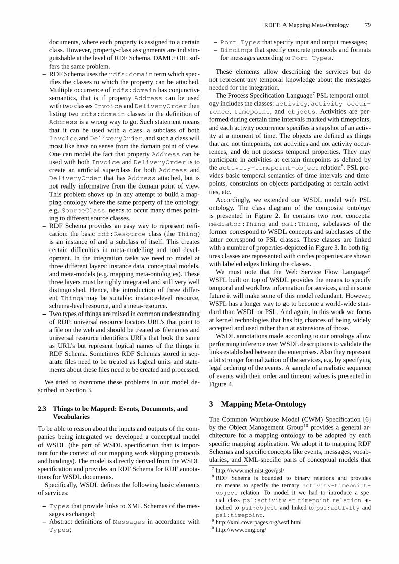
RDFT: A Mapping Meta-Ontology 79
documents, where each property is assigned to a certainclass. However, property-class assignments are indistin-guishable at the level of RDF Schema. DAML+OIL suf-fers the same problem.
– RDF Schema uses therdfs:domain term which spec-ifies the classes to which the property can be attached.Multiple occurrence ofrdfs:domain has conjunctivesemantics, that is if propertyAddress can be usedwith two classesInvoice andDeliveryOrder thenlisting two rdfs:domain classes in the definition ofAddress is a wrong way to go. Such statement meansthat it can be used with a class, a subclass of bothInvoice andDeliveryOrder , and such a class willmost like have no sense from the domain point of view.One can model the fact that propertyAddress can beused with bothInvoice andDeliveryOrder is tocreate an artificial superclass for bothAddress andDeliveryOrder that hasAddress attached, but isnot really informative from the domain point of view.This problem shows up in any attempt to build a map-ping ontology where the same property of the ontology,e.g.SourceClass , needs to occur many times point-ing to different source classes.
– RDF Schema provides an easy way to represent reifi-cation: the basicrdf:Resource class (theThing )is an instance of and a subclass of itself. This createscertain difficulties in meta-modelling and tool devel-opment. In the integration tasks we need to model atthree different layers: instance data, conceptual models,and meta-models (e.g. mapping meta-ontologies). Thesethree layers must be tighly integrated and still very welldistinguished. Hence, the introduction of three differ-ent Thing s may be suitable: instance-level resource,schema-level resource, and a meta-resource.
– Two types of things are mixed in common understandingof RDF: universal resource locators URL’s that point toa file on the web and should be treated as filenames anduniversal resource identifiers URI’s that look the sameas URL’s but represent logical names of the things inRDF Schema. Sometimes RDF Schemas stored in sep-arate files need to be treated as logical units and state-ments about these files need to be created and processed.
We tried to overcome these problems in our model de-scribed in Section 3.
2.3 Things to be Mapped: Events, Documents, andVocabularies
To be able to reason about the inputs and outputs of the com-panies being integrated we developed a conceptual modelof WSDL (the part of WSDL specification that is impor-tant for the context of our mapping work skipping protocolsand bindings). The model is directly derived from the WSDLspecification and provides an RDF Schema for RDF annota-tions for WSDL documents.
Specifically, WSDL defines the following basic elementsof services:
– Types that provide links to XML Schemas of the mes-sages exchanged;
– Abstract definitions ofMessages in accordance withTypes ;
– Port Types that specify input and output messages;– Bindings that specify concrete protocols and formats
for messages according toPort Types .
These elements allow describing the services but donot represent any temporal knowledge about the messagesneeded for the integration.
The Process Specification Language7 PSL temporal ontol-ogy includes the classes:activity , activity occur-rence , timepoint , and objects . Activities are per-formed during certain time intervals marked with timepoints,and each activity occurrence specifies a snapshot of an activ-ity at a moment of time. The objects are defined as thingsthat are not timepoints, not activities and not activity occur-rences, and do not possess temporal properties. They mayparticipate in activities at certain timepoints as defined bytheactivity-timepoint-object relation8. PSL pro-vides basic temporal semantics of time intervals and time-points, constraints on objects participating at certain activi-ties, etc.
Accordingly, we extended our WSDL model with PSLontology. The class diagram of the composite ontologyis presented in Figure 2. In contains two root concepts:mediator:Thing and psl:Thing , subclasses of theformer correspond to WSDL concepts and subclasses of thelatter correspond to PSL classes. These classes are linkedwith a number of properties depicted in Figure 3. In both fig-ures classes are represented with circles properties are shownwith labeled edges linking the classes.
We must note that the Web Service Flow Language9
WSFL built on top of WSDL provides the means to specifytemporal and workflow information for services, and in somefuture it will make some of this model redundant. However,WSFL has a longer way to go to become a world-wide stan-dard than WSDL or PSL. And again, in this work we focusat kernel technologies that has big chances of being widelyaccepted and used rather than at extensions of those.
WSDL annotations made according to our ontology allowperforming inference over WSDL descriptions to validate thelinks established between the enterprises. Also they representa bit stronger formalization of the services, e.g. by specifyinglegal ordering of the events. A sample of a realistic sequenceof events with their order and timeout values is presented inFigure 4.
3 Mapping Meta-Ontology
The Common Warehouse Model (CWM) Specification [6]by the Object Management Group10 provides a general ar-chitecture for a mapping ontology to be adopted by eachspecific mapping application. We adopt it to mapping RDFSchemas and specific concepts like events, messages, vocab-ularies, and XML-specific parts of conceptual models that
7 http://www.mel.nist.gov/psl/8 RDF Schema is bounded to binary relations and provides
no means to specify the ternaryactivity-timepoint-object relation. To model it we had to introduce a spe-cial class psl:activity at timepoint relation at-tached topsl:object and linked topsl:activity andpsl:timepoint .
9 http://xml.coverpages.org/wsfl.html10 http://www.omg.org/

80 Borys Omelayenko
mediator:Thing
mediator:Vocabulary
psl:object
psl:Thing
psl:activity_occurrence
mediator:Event
psl:timepoint
mediator:Document mediator:Message
psl:activity_at_timepoint_relation
psl:activitymediator:PortType
isaisa
isa
isa isaisaisa isa isa
isaisa isa
isaisa
mediator:Thing
mediator:Vocabulary
psl:object
psl:Thing
psl:activity_occurrence
mediator:Event
psl:timepoint
mediator:Document mediator:Message
psl:activity_at_timepoint_relation
psl:activitypsl:activitymediator:PortType
isaisa
isa
isa isaisaisa isa isa
isaisa isa
isaisa
Fig. 2.WSDL extension (class diagram)
mediator:PortType
mediator:Document
mediator:Event
mediator:Message
mediator:Vocabulary
psl:object
psl:activity_at_ timepoint_relation
psl:timepoint
psl:activity
psl:activity_occurrencemediator:
Documents
*
mediator:Events*
mediator:Messages*
mediator:Vocabularies*
isa
psl:at
psl:in
psl:before*
psl:begin*psl:end*
psl:occurrence_of_activity psl:exists_at
psl:participates_activity_ timepoint*
isa
isa
mediator:EventActivitymediator:EventDocument
psl:is_occurring_at*
isa
Fig. 3.WSDL extension (descriptions of classes)
Fig. 4.Event sequence
occur in the business integration tasks. CWM specifies thefollowing basic primitives for mapping:
– Class TransformationMap a subclass of theTransformation class. The former is a container forClassifierMaps .
– Each ClassifierMap links two groups of classeswith two properties source and target with multiple oc-
currence referring to the groups of source and targetclasses being mapped with the map.
– EachClassifierMap connects two groups of proper-ties with thefeatureMap property that links it to theFeatureMap class connectingsource andtargetproperties (called features).FeatureMap also includesa link to anotherClassifierMap mapping propertyvalues.
– Each ClassifierMap may connect a groupof properties and a group of classes with theClassifierFeatureMap class referenced viathecfMapproperty .
The CWM model concerns mapping generic conceptualmodels and seems to be too expressive for our needs. Map-ping classes that normally refer to physical objects to proper-ties that refer to properties of those is a large source of mis-understanding in the business tasks, while conceptually thereis nothing wrong with it. In RDF meta-model both propertiesand classes are treated in a uniform way, while at the levelof models those are clearly differentiated. Accordingly, weneed to skip it in our mapping framework.
The RDFT (RDF Transformation) mapping meta-ontology11 specifies a small language for mapping XMLDTDs to/and RDF Schemas specially targeted for businessintegration tasks. The class diagram for the basic top-levelclasses is presented in Figure 5 using the same notation asour previous drawings.
11 http://www.cs.vu.nl/ borys/RDFT

RDFT: A Mapping Meta-Ontology 81
RDFT:RDFBridge
RDFT:Bridge
RDFT:VocabularyMap
RDFT:Map
RDFT:Interface
RDFT:RolesRDFT:Event2Event
RDFT:DocumentMap
RDFT:XMLBridge
RDFT:EventMap
isa
isa
RDFT:RDFBridges*
RDFT:IncludedMaps*
RDFT:InputInterface* RDFT:OutputInterface*
RDFT:PrivateRoleRDFT:PublicRoleisa
RDFT:DocumentMaps*isa
isa
RDFT:RDFBridges*
RDFT:VocabularyMaps*RDFT:XMLBridges*
isa
RDFT:EventBridges*
Fig. 5.Main RDFT classes: Bridge, Map, Interface, BridgeRelation, and Roles
The basic RDFT class isBridge that connects two con-cepts (similar to the CWM’sClassifierMap ). Bridgedescribes common properties of bridges allowing only one-to-many and many-to-one bridges opposite to CWM allow-ing many-to-many mappings12.
The bridges also contain theRelation propertypointing to one of the relations subclassed from theBridgeRelation class:EquivalenceRelation orVersionRelation .
– Equivalence bridges specify that the source elementof a one-to-many bridge is equivalent to the target set ofelements, and the source set of elements is equivalent tothe target element for many-to-one bridges. E.g. a one-to-many bridge connecting a source class to a group oftarget classes states that the target group is semanticallyequivalent with respect to the instance data transforma-tion task to the source element.
– Version bridges specify that the target set of elementsform a (later) version of the source set of elements.Opposite to equivalence bridges, they assume that bothsource and target concepts belong to the same domain(or document standard), and may refer to two conceptswith the same name (but different namespaces indicatingversions), and imply that all the relations that held for the
12 Largely the objective of CWM is to model, i.e. to understand thethings, while the objective of RDFT is to be able to transforminstance data according to the mappings that imposes certain ar-chitectural restrictions.
original concept must hold for the versioned concept, ifthe opposite is not stated explicitly.
Several types ofBridges are defined in RDFT:
– Event2Event bridges link different events, specifytemporal event generation conditions, and link the eventsto the messages transmitted with them. They connect in-stances of the meta-classmediator:Event .
– Two kinds of RDFbridges : Class2Class andProperty2Property bridges between RDFSchema classes and properties.Class2Classbridges containSourceClass and TargetClassproperties pointing to rdfs:Class instances.Property2Property bridges containsSourceProperty and TargetProperty prop-erties pointing tordf:Property instances. Again,only one-to-many and many-to-one bridges are allowedin RDFT. In RDF Schema properties are defined asfirst-class objects together with classes, and they capturemost of domain knowledge. Classes mostly specifyaggregation of properties, and thus we do not includeclass-to-property and property-to-class bridges in RDFT.
– Four kinds of XMLBridges : Tag2Class andTag2Property bridges link source XML DTDtags and target RDF Schema classes and properties.Class2Tag and Property2Tag bridges connectRDF Schema classes and properties, and the ele-ments of the target DTD. These are constructed fromSourceTag andTargetTag properties in addition to

82 Borys Omelayenko
theSource/Target-Class/Property propertiesmentioned above.
In some cases it is possible to declaratively specify the cor-respondence of property or class values linked by a bridge(e.g. by specifying the set ofClass2Class bridges). If itis not feasible then we use theExpression property ofa Bridge . It specifies an XPath [7] expression transform-ing instance data. XPath defines the means for two tasks:addressing data elements in XML documents and perform-ing element or attribute value transformations (Chapter 4 ofthe specification ). We use only the second part of the XPathfunctions (e.g.substring_before ).
We need to create an ontology of a DTD to representdifferent DTDs in our framework and performing infer-ence involving DTD elements and attributes (e.g. to checkwhether all the elements are mapped with RDFT bridges).The DTDs themselves are available to the mediating ser-vice, and only DTD elements and attributes must be anno-tated. Accordingly, we introduce two classes to representthem: XMLElement and XMLAttribute , subclasses ofXMLTag. PropertiesSourceTag and TargetTag takeXMLTag instances as their values.
Several assignments of a property to a class (e.g. a prop-erty with multiple cardinality) are not distinguishable in RDFSchema because they are not that significant from the model-ing point of view. However, they are crucially important fromthe instance data transformation perspective, and we intro-duce classRole to specify each property-class assignment.
The bridges are grouped into maps. EachMap is acollection of bridges serving a single purpose. The mapsare identified by their names13 and form minimal reusablemodules of RDFT bridges. EachMap can include othermaps (theIncludedMaps property) and serves as a con-tainer for Bridge s (the Bridges property). The mapsuse some class and property names within the bridgesinside the maps and may be reused with other namespassed as formal parameters. These parameters are formal-ized with theInterface class depicted in Figure 5. EachInterface class contains two properties:PublicRoleand PrivateRole that specify the correspondence be-tween external and internal names, correspondingly.
Connecting two services means connecting their events(instantiating theEventMap depicted in Figure 5) consist-ing of Event2Event bridges. Each of the bridges points toaDocumentMap aligning the documents attached to events,and, in turn, consisting ofXMLBridges , RDFBridgesandVocabularyMaps .
We do not impose any restriction on class names of a userontology conforming the RDFT meta-ontology. Instead, allof them are marked as instances of RDFT meta-classes, asit is illustrated with aClass2Class bridge in Figure 8. Inthe figure user’s classes are marked asS0, S1, andT0, and abridge connecting them is marked withB_01.
It is important to differentiate the role of RDFT as ameta-ontology versus a template. Assume a definition of13 In this case we have a collision of resource identifiers URI’s
that’s are used in RDF Schema and represent a logical name with-out any associated physical object and resource locators URL’sthat point to files somewhere on the Web. The maps are identi-fied by their URI’s but should be accessible via their URL’s asreusable files with bridges.
a metaclassmCand a definition of propertymP with do-main mCand rangerdfs:Literal . ClassiC , an RDFinstance ofmCwill be a class definition that in addition toRDF Schema standard properties for a class definition (e.g.rdfs:subClassOf ) possesses instantiated literal prop-erty iC .
However, we would expectproperty definitionof iC to beapplicable tomCrather than theproperty itself. So, we wouldrather need to call our RDFT ontology as a template ontol-ogy, while the term ‘template’ is not specified within RDFSchema. The instantiation semantics of RDF Schema classdefinitions, opposite to properties, seems to be acceptable forour needs.
Another important notion related to RDFT is its complete-ness, i.e. possibility to map arbitrary RDF Schemas. The term‘map’ can be defined in different ways and each definition as-sumes a set of relations that need to be represented with themaps. In our case we try to map different part-of decompo-sitions of object’s properties, and one-to-many and many-to-one bridges seem to be sufficient for that. For extracting partsof properties we use quite expressive XPath language.
The main contribution of any architectural solution is toextract several most important tasks in the area and providethe means restricted in expressiveness but explicitly support-ing these tasks. The unsupported cases may be handled byprogramming in expressive languages. We follow this princi-ple in our mapping framework.
SourceClass TargetClassBridgeM
eta-
Ont
olog
yO
ntol
ogy B_01
S0
rdfs:Class rdfs:Class
S1
T0
rdf:Property
rdfs:Resource
PS00
PS01PT00
Fig. 8.The use of RDFT meta-ontology
4 Using Expressive Extensions of RDFSchema
It is always possible to express RDFT with expressive ex-tensions of RDF Schema. However, before using them weshould always ensure that this does not make things worse.People using DAML+OIL use specific DAML+OIL exten-sions quite seldom, and mostly they pick some minor butconvenient extensions ignoring really expressive languageconstructs [8].
The business integration scenario is more specific and re-stricted that a generic modeling scenario. Business objectsare quite simple and well-defined. Unlike the general case,most or all the objects might have physical representation,they are explicitly named, and are a part of a very shallowtaxonomy.
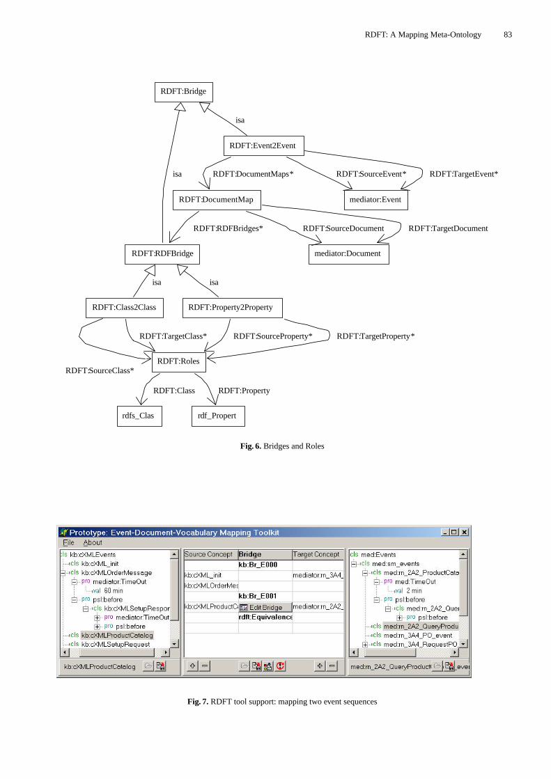
RDFT: A Mapping Meta-Ontology 83
RDFT:Class2Class
RDFT:RDFBridge
RDFT:Roles
RDFT:Bridge
RDFT:Property2Property
rdfs_Clas rdf_Propert
mediator:Document
RDFT:Event2Event
RDFT:DocumentMap mediator:Event
isa
RDFT:SourceClass*
RDFT:TargetClass*
isa
isa
RDFT:SourceProperty* RDFT:TargetProperty*
RDFT:Class RDFT:Property
isa
RDFT:DocumentMaps* RDFT:SourceEvent* RDFT:TargetEvent*
RDFT:RDFBridges* RDFT:SourceDocument RDFT:TargetDocument
Fig. 6.Bridges and Roles
Fig. 7.RDFT tool support: mapping two event sequences

84 Borys Omelayenko
Accordingly, we do not see any immediate needs for usingmore expressive language than RDF Schema.
The intention of the mapping is to be able parse the mapsand generate XML transformation scripts able to translate in-stance XML documents attached to the messages. That is,for each target DTD element we need to trace which prop-erty of which object corresponds to this element, and thentrace whether there is a map to a document from the sourcemodels. Finally, we need to find out which element from thesource DTDs contains the original description of the prop-erty.
We need to use search-based inference engines, e.g.CLIPS14, to find these chains. Then, each chain needs to betranslated into an XML transformation language, e.g. XSLT.
5 Tool Support
We are currently developing a prototype tool providing an ad-vanced map browsing and editing facilities and guiding theuser through the event, document and vocabulary integrationtasks. All these tasks are quite similar from the implementa-tion point of view: all of them can be treated as RDF Schemamapping tasks. In the case of event mapping (see Figure 7 fora screenshot) the prototype tool allows the user to browse twoRDF Schemas representing two event sequences and createRDFT maps between the schemas. Each bridge can be editedin details and necessary vocabulary bridges are edited withthe same RDFT map editor applied to document schemas in-stead of event sequences.
Several important features are still under development inthe tool: an interface to online web service described inWSDL, an inference engine, and an RDFT execution mod-ule. In addition, there are a number of small things that aretoo annoying to ignore them and too unimportant to talkabout them.
6 Conclusions
We proposed a service integration architecture to match thefollowing requirements:
– Allow switching from document transformation and ex-change between the services to concept and model ex-change.
– Annotate WSDL descriptions with concepts from tem-poral PSL ontology and some concepts from the businessintegration domain.
– Contain a mapping meta-ontology specifying map-ping information between DTD elements, RDF Schemaclasses and properties, and events.
– Allow performing inference-based checks for complete-ness and consistency of the mappings.
– Allow compiling the data transformation chains repre-sented by the mappings to a low-level XML transforma-tion language.
In the paper we present our current progress in satisfyingthese requirements, namely switching between document-based to concept-based integration, WSDL annotation, map-ping meta-ontology and preliminary steps in inference-basedvalidation and compilation.14 http://www.ghg.net/clips/CLIPS.html
Acknowledgements.The author would like to thank Di-eter Fensel, Christoph Bussler, Michel Klein, and VolodymyrZykov for their helpful discussions and the reviewers fortheir comments.
References
1. Bae, H., Kim, Y.: A Document-Process Association Model forWorkflow Management. Computers in Industry47 (2002) 139–154
2. Bussler, C.: Modeling and Executing Semantic B2B Integra-tion. In: Proceedings of the 12th International Workshop on Re-search Issues on Data Engineering: Engineering E-Commerce/ E-Business Systems (RIDE-2EC’2002) (In conjunction withICDE-2002), San Jose, USA, IEEE CS Press (2002)
3. Mello, R., Heuser, C.: A Rule-Based Conversion of a DTD toa Conceptual Schema. In Kunii, H., Jojodia, S., Solvberg, A.,eds.: Conceptual Modeling - ER’2001. Number 2224 in LNCS,Yokohama, Japan, Springer (2001) 133–148
4. Lee, D., Chu, W.: CPI: Constraint-Preserving Inlining algorithmfor mapping XML DTD to relational schema. Data and Knowl-edge Engineering39 (2001) 3–25
5. Brickley, D., Guha, R.: Resource Description Framework (RDF)Schema Specification 1.0. Technical report, W3C CandidateRecommendation, March 27 (2000)
6. CWM: Common Warehouse Model Specification. Technicalreport, Object Management Group (2001)
7. Clark, J.: XSL Transformations (XSLT). Technical report, W3CRecommendation, November 16 (1999)
8. van Harmelen, F.: The Complexity of the Web Ontology Lan-guage. IEEE Intelligent Systems17 (2002) 71–73

Enabling Services for Distributed Environments: Ontology Extraction andKnowledge Base Characterisation
Derek Sleeman1, Stephen Potter2, Dave Robertson2, and W. Marco Schorlemmer2
1 Department of Computing Science,University of Aberdeen
[email protected] Division of Informatics,University of Edinburgh
[email protected], {dr,marco }@dai.ed.ac.uk
Abstract. Existing knowledge base resources havethe potential to be valuable components of theSemantic Web and similar knowledge-based envi-ronments. However, from the perspective of theseenvironments, these resources are often under-characterised, lacking the ontological and structuralcharacterisation that would enable them to be ex-ploited fully.In this paper we discuss two currently independentservices, both integrated with their environment viaa brokering mechanism. The first of these servicesis an ontology extraction tool, which can be used toidentify ontological knowledge implicit in a knowl-edge base. The second service involves characteris-ing a given knowledge base in terms of the topic itaddresses and the structure of its knowledge. Thischaracterisation should permit a knowledge base tobe located and assessed as a potential candidate forre-use in a more intelligent and flexible manner.The discussion of some related research into broker-ing systems illustrates the roles that these servicescan play in distributed knowledge architectures asprecursors to problem-directed transformation andreuse of knowledge resources.
1 Introduction
The principal challenge for the Semantic Web community isto make machine-readable much of the material that is cur-rently human-readable, and thereby enrich web operationsfrom their current information-based state into a knowledge-centric form. Towards this end, for instance, the IBROWproject is addressing the complex task of developing a bro-kering system which, given a knowledge base/knowledgesource and a specification of the processing to be performed,would find an appropriate problem solver and perform anynecessary transformation of the knowledge sources [1]. Thefocus of this paper is primarily on our research into two com-plementary, and currently independent, techniques that en-able brokering systems to become more effective and moreintelligent. These techniques, then, are intended to facilitatethe reuse and transformation of knowledge.
The first of these techniques involves the extraction of do-main ontologies from existing knowledge bases. Work on on-tologies has played a central role in recent years in Knowl-edge Engineering, as ontologies have increasingly come tobe seen as the key to making (especially web) resourcesmachine-readable and -processable. Systems have been im-plemented which help individuals and groups develop on-tologies, detect inconsistencies in them, and merge two or
more. Ontologies are seen as theessenceof a knowledgebase, that is, they capture, in some sense, what is commonlyunderstood about a topic by domain experts. For a discussionof how ontologies are often developed, see [2]. Recently, sys-tems have been implemented which help domain experts lo-cate domain concepts, attributes, values and relations in tex-tual documents. These systems also often allow the domainexpert to build ontologies from these entities; it has beenfound necessary, given the shortcomings of the particular textprocessed, to allow the domain expert, as part of the knowl-edge modelling phase, to add entities which are thought tobe important, even if they are not found in the particular text[3].
Reflecting on this process has given us the insight thatknowledge bases3 themselves could act as sources of on-tologies, as many programs essentially contain a domain on-tology which although it may not be complete, is, in somesense, consistent. (Since if it were inconsistent this wouldlead, under the appropriate test conditions, to operationalproblems of the system in which the ontology is embedded).Thus, the challenge now becomes one of extracting ontolo-gies from existing knowledge-based systems. The followingsection describes one approach for doing this, from, in thefirst instance, Prolog knowledge bases. As well as enablingtheir re-use, this technique can also be seen as performing atransformation of these knowledge bases into their implicitontological knowledge.
In any distributed environment, before it can be re-usedor transformed, an appropriate knowledge resource must belocated. Doing this efficiently is not a trivial task, since itrequires the ability to identify that a resource fulfils certaindomain requirements and structural criteria without entailingthe need to analyse the entire content of that resource. Thesecond technique discussed in this paper addresses this prob-lem, attempting to summarise the essentials of a knowledgebase for this particular purpose.
The rest of the paper is structured as follows. Section 2 de-scribes, with examples, the technique for acquiring ontolog-ical knowledge from knowledge bases in a (semi-)automaticfashion. Section 3 discusses the approach to characterisingknowledge bases, describing them in a concise and succinct
3 Throughout this paper, by “knowledge base” we mean someknowledge-bearing computer program, not necessarily expressedin some dedicated knowledge representation language, but forwhich the decision has been made to express the knowledge ata semantic, conceptual level. For our purposes, however, we as-sume that an explicit ontology describing the terms of such aknowledge base isnotavailable.

86 Derek Sleeman et al.
manner to better allow their re-use. Section 4 gives a briefoverview of a brokering system, in order to illustrate the rolethat the two techniques can play in facilitating knowledgeservices within distributed environments. Section 5 discussesrelated work, and, to conclude, Section 6 summarises the pa-per.
2 Extracting Ontologies from PrologKnowledge Bases
The method used to hypothesise ontological constraints fromthe source code of a knowledge base is based on Clark’s com-pletion algorithm [4]. Normally this is used to strengthenthe definition of a predicate given as a set of Horn clauses,which have single implications, into a definition with double-implication clauses. Consider, for example, the predicatemember(E,L) which is true ifE is an element of the list,L:
member(X, [X|T ])member(X, [H|T ]) ← member(X,T )
The Clark completion of this predicate is:
member(X,L) ↔ L = [X|T ] ∨ (L = [H|T ] ∧member(X,T ))(1)
Use of this form of predicate completion allows us to hy-pothesise ontological constraints. For example, if we wereto assert thatmember(c, [a, b]) is a true statement in someproblem description then we can deduce that this is inconsis-tent with our use ofmember as constrained by its completionin expression (1) above because the implication below, whichis an instance of the double implication in expression (1), isnot satisfiable.
member(c, [a, b]) → [a, b] = [c|T ] ∨ ([a, b] = [H|T ] ∧member(c, T ))
(2)
Normally Clark’s completion is used for transformationof logic programs where we are concerned to preserve theequivalence between original and transformed code. It there-fore is applied only when we are sure that we have a completedefinition for a predicate (as we had in the case ofmember).However, we can still apply it in “softer” cases where defi-nitions are incomplete. Consider, for example, the followingincomplete definition of the predicateanimal(X):
animal(X) ← mammal(X)animal(X) ← fish(X)
Using completion as above, we could derive the constraint:
animal(X) → mammal(X) ∨ fish(X)
This constraint is over-restrictive since it asserts that an-imals can only be mammals or fish (and not, for instance,insects). Nevertheless, it is useful for two purposes:
– As a basis for editing a more general constraint on theuse of the predicate ‘animal’. We describe a prototypeextraction tool, which includes a basic editor, for thesesorts of constraints in Section 2.1.
– As a record of the constraints imposed by thisparticularuse of the predicate ‘animal’. We describe an automateduse of constraints under this assumption in Section 2.2.
2.1 A Constraint Extraction Tool: the EXTRACTexPSystem
We have produced a basic system for extracting ontologicalconstraints of the sort described above from Prolog sourcecode. Our tool can be applied to any standard Prolog pro-gram but is only likely to yield useful constraints for predi-cates which contain no control-effecting subgoals (althoughnon-control-effecting goals such aswrite statements are ac-commodated). While, in theory at least, the approach can beapplied to programs of any size, we will now demonstratethe current tool using an example involving a small numberof predicates.
Figure 1 shows the tool applied to a simple example of an-imal classification, following the introduction of the previoussection. The Prolog code is:
animal(X) :- mammal(X).animal(X) :- fish(X).mammal(X) :- vertebrate(X), warm_blooded(X),
milk_bearing(X).fish(X) :- vertebrate(X), cold_blooded(X), aquatic(X),
gill_breathing(X).
which corresponds to the Horn Clauses:
animal(X) ← mammal(X)animal(X) ← fish(X)
mammal(X) ← vertebrate(X) ∧ warm blooded(X)∧milk bearing(X)
fish(X) ← vertebrate(X) ∧ cold blooded(X) ∧ aquatic(X)∧gill breathing(X)
(3)
The constraints extracted for this program (seen in thelower window of Figure 1) are:
animal(X) → mammal(X) ∨ fish(X)fish(X) → vertebrate(X) ∧ cold blooded(X) ∧ aquatic(X)
∧gill breathing(X)mammal(X) → vertebrate(X) ∧ warm blooded(X)
∧milk bearing(X)
(4)
If it is deemed necessary, the user of the tool can thenchoose to edit manually the constraints. We show in Sec-tion 2.2 how these constraints, which, in this case, wereextracted completely automatically from the Prolog sourcecode, can be used to check another Prolog program purport-ing to adhere to the same ontology.
2.2 Ontological “Safe Envelopes”
The idea of running programs within ontological “safe en-velopes” was introduced in [5]. Programs are run accordingto the normal execution control regime of the language con-cerned but a record is kept of the cases where the executionuses terminology which does not satisfy a given set of onto-logical constraints. When this happens we say the executionhas strayed outside its safe envelope (from an ontologicalpoint of view). This sort of checking is not intended to al-ter the execution of the program in any significant way, onlyto pass back retrospective information about the use of ter-minology during an execution. This style of checking can beimplemented elegantly for languages, such as Prolog, whichpermit meta-interpretation, allowing us to define the controlstructure for execution explicitly and then to augment thiswith appropriate envelope checking. The Horn clauses shown

Enabling Services for Distributed Environments 87
Fig. 1.Ontology extraction tool
in expression (5) provide a basic example (extended versionsof this appear in [5]).
solve(true, {})solve((A ∧ B), Ea ∪ Eb) ← solve(A,Ea) ∧ solve(B,Eb)solve((A ∨ B), E) ← solve(A,E) ∨ solve(B,E)solve(X,E ∪ {C|(X → C ∧ not(C))}) ← clause(X,B)
∧solve(B,E)
(5)
In the expressions above,clause(X,B) means that thereis a clause in the program satisfying goalX contingent onconditions,B (where there are no conditions,B has the valuetrue). The implicationX → C is an ontological constraintof the sort we are able to derive in the extraction tool of Sec-tion 2.1. The operators←,∧,∨, and∪ are the normal logicaloperators for (left) implication, conjunction, disjunction andunion, whilenot(C) is the closed-world negation of condi-tionC.
The effect of the meta-interpreter above is to test each suc-cessful goal in the proof tree for a query against the availableontological constraints. The first clause of (5) matches thegoaltrue, which, as might be expected, violates no ontologi-cal constraints (and so, the empty set is returned). The secondand third clauses deal with conjunctions and disjunctions ofgoals respectively. In the case of the former, the union of thesets of violated constraints is returned; in the latter case, theset generated by the succeeding goal is returned.
In the final clause, if an assertedclause(X,B) is foundwhich satisfies the current goal,X, then the conditions,B, ofthis goal become subgoals of the interpreter, while the goalitself is tested against the ontological constraints. If a con-straint exists (X → C) that is not found to be consistent withthe known facts of the current situation (not(C), under theclosed-world assumption), then it is added to the set of vi-olated constraints. When a goal and its subgoals have beensolved, then the interpreter exits with success, returning theset of all violated constraints; if, on the other hand, a goalcannot be solved, then the interpreter fails.
For example, suppose we have the following informationabout animals,a1 anda2 , using the animal ontology of Sec-tion 2.1.
animal(a1).vertebrate(a1).warm_blooded(a1).milk_bearing(a1).animal(a2).vertebrate(a2).cold_blooded(a2).terrestrial(a2).
We could query this database in the normal way, for ex-ample by giving the goalanimal(X) which yields so-lutions with X = a1 and X = a2. If we want to per-form the same query while checking for violations ofthe ontological constraints we extracted in Section 2.1,then each of these facts is asserted in the form, e.g.,clause(animal(a1),true) , and we pose the queryvia the meta-interpreter we defined above — the appropri-ate goal beingsolve(animal(X), C) . This will yieldtwo solutions, as before, but each one will be accompaniedby corresponding ontological constraint violations (as corre-sponding instances of the variableC). The two solutions are:
X = a1 C = {}X = a2 C = {mammal(a2) ∨ fish(a2)}
When presented with the first goal,animal(a1) , the interpreter matches this withclause(animal(a1),true) from the database; thepreconditiontrue generates no ontological problems, andfrom expression (4), the constraintmammal(a1)∨fish(a1)is placed onanimal(a1) . Now, the additional facts inthe database and the other ontological constraints allow theconclusionmammal(a1) to be drawn, so it isnot the casethat not(mammal(a1) ∨ fish(a1)) is true (as tested bythe fourth clause of the interpreter), so no constraints areviolated, and the empty set is returned.
The solution of the second goal,animal(a2) proceedsin a similar fashion, but in this instance, the constraints

88 Derek Sleeman et al.
and database facts do not allow eithermammal(a2) orfish(a2) to be proved. Hence, under the closed-world as-sumption,not(mammal(a2)∨fish(a2)) is true, and so thisconstraint has been violated (this in spite of the fact that thedatabase allows the goalanimal(a2) itself to be proved).
2.3 Extracting Ontologies from Other Sorts ofKnowledge Bases
The majority of knowledge sources are not in Prolog so forour extraction tool to be widely applicable it must be able todeal with other sorts of source code. This would be very hardindeed if it were the case that the ontological constraints weextract have to encompass the entire semantics of the code.Fortunately, we are not in that position because it is suffi-cient to extract some of the ontological constraints from thesource code — enough to give a partial match when broker-ing or to give a starting point for constraint editing. The issuewhen moving from a logic-based language, like Prolog, to alanguage perhaps having more procedural elements is howmuch of the ontological structure we can extract. We discussthis using CLIPS as an example.
Suppose we have the following CLIPS facts and rules:
(deftemplate person "the person template"(slot name)(slot gender (allowed-symbols female male)
(default female))(slot pet))
(deftemplate pet "the pet template"(slot name)(slot likes))
(deffacts dating-agency-clients(person (name Fred) (gender male) (pet Tiddles))(person (name Sue) (pet Claud))(person (name Tom) (gender male) (pet Rover))(person (name Jane) (pet Squeak))(pet (name Tiddles) (likes Claud))(pet (name Claud) (likes Tiddles))(pet (name Rover) (likes Rover))(pet (name Squeak) (likes Claud)))
(defrule compatible(person (name ?person1) (pet ?pet1))(person (name ?person2) (pet ?pet2))(pet (name ?pet1) (likes ?pet2))=>(assert (compatible ?person1 ?person2)))
To extract ontological constraints from these using the cur-rent version of the EXTRACTexP tool we must translatethese CLIPS rules into Horn clauses. We outline below, ininformal terms, the transformation algorithm needed for thistask:
– For each CLIPS rule, take the assertion of the rule asthe head of the Horn clause and the preconditions as thebody of the clause.
– Consider each head, body or CLIPS fact as an objectterm.
– For each object term, refer to itsdeftemplate defi-nition and translate it into a series of binary relations asfollows:• Invent an identifier,I, for the instance of the object.• The relationobject(T, I) gives the type of object,T , referred to by instanceI.• The relationA(I, V ) gives the value,V , for an at-
tributeA of instanceI.
Applying this algorithm to our CLIPS example yields theHorn clauses shown below:
compatible(Person1, Person2)←
object(person,O1) ∧ name(O1, Person1) ∧ pet(O1, Pet1)∧object(person,O2) ∧ name(O2, Person2) ∧ pet(O2, Pet2)∧object(pet, O3) ∧ name(O3, Pet1) ∧ likes(O3, Pet2)
object(person, p1) name(p1, fred) gender(p1,male) pet(p1, tiddles)object(person, p2) name(p2, sue) gender(p2, female) pet(p2, claud)object(person, p3) name(p3, tom) gender(p3,male) pet(p3, rover)object(person, p4) name(p4, jane) gender(p4, female) pet(p4, squeak)
object(pet, x1) name(x1, tiddles) likes(x1, claud)object(pet, x2) name(x2, claud) likes(x2, tiddles)object(pet, x3) name(x3, rover) likes(x3, rover)object(pet, x4) name(x4, squeak) likes(x4, claud)
This does not capture the semantics of the original CLIPSprogram, since, for example, it does not express notions ofstate necessary to describe the operation of CLIPS workingmemory. It does, however, chart the main logical dependen-cies, which is enough for us then to produce ontological con-straints directly from EXTRACTexP. This translation-basedapproach is the most direct route to constraint extraction us-ing our current tool but we anticipate more sophisticatedroutes which perhaps do not translate so immediately to Hornclauses.
Extending this technique beyond knowledge representa-tion languages to enable the extraction of ontological infor-mation from conventional procedural languages such as Cwould prove difficult. Programmers of these languages haveno incentive to express their code at a conceptual level, withthe result that the ontological constraints, insofar as they areexpressed, tend to be embedded in the control elements andstructure of the code to a greater extent. Code written inobject-oriented languages, such as Java and C++, is poten-tially more susceptible to ontological extraction of this sort,since the object-oriented paradigm encourages the program-mer to codify the concepts of the domain in an explicit andstructured manner (the CLIPS templates in the above exam-ples can be viewed as simple objects in this sense). However,we have yet to investigate the possibilities of mining conven-tional object-oriented code for ontological information.
3 Characterising Knowledge Sources in aDistributed Environment
Reuse of both problem solving components and knowledgesources is a holy grail of knowledge engineering. While therehas been considerable discussion of re-use of problem solv-ing algorithms in Knowledge Engineering [6] and in Soft-ware Engineering [7], there has been much less work onreuse of knowledge bases/sources. But if a company hasspent a great deal of time and resource in developing aknowledge base for, say, the design of an engine, it wouldseem prudent, if it were possible, to use that same knowl-edge as the basis for a diagnostic knowledge base. In generalone could imagine designers making such requests over theinternet/company intranet:
“I am looking for a knowledge base which discussesthe design specification of machines for grape har-vesting.”

Enabling Services for Distributed Environments 89
In general, these requests can be characterised as “Requireknowledge base on topic T” or, more likely, “Require knowl-edge base on topic T where the knowledge conforms to cer-tain constraints C”. The ability to respond to a request of thisform would be an important step towards creating the sort ofenvironment in which the re-use of knowledge componentsis a commonplace.
We plan to address such knowledge base characterisationissues as follows: Firstly, we will decide what is the princi-pal topic, T, of a given knowledge base. Secondly we willdevelop a series of other programs (orfilters if one uses aLARKS-like nomenclature [8]) to look for different kinds ofstructure/constraints in the knowledge base. Each of these isdealt with briefly below.
3.1 Knowledge Base Topic Identification
Our current EXTRACTexP system can analyse a Prologknowledge base, and can extract all the predicates (and theirarities) which it contains (see top window of the tool in Fig-ure 1). Using knowledge of Prolog, its basic constructs likeread , write , etc. are discarded, leaving a set of domainterms. These terms could then be propagated through a pre-defined ontology (c.f. the spreading activation through a Se-mantic Network which was postulated in the ’70s as a possi-ble model to explain human focus of attention change [9]).This ontology would contain relevant concepts within theuniverse of discourse.
As a simple example, suppose we have the ontology de-picted in Figure 2. If the conceptsApples andPears werepassed to the system, it would suggest thatFruit mightbe the relevant focus of the knowledge base. Similarly, pro-viding the set{Apples, Pears, Potatoes, Car-rots} would suggest thatFruit-Vegetables mightbe the focus, and if one provided{Apples, Pota-toes, Chicken, Game} it would suggestFood mightbe the focus. We plan subsequently to extend the system sothat it will be able to detect two or more principal topics,e.g.Fruit andFood Processing , drawn from a number ofcomplementary ontologies.
Fig. 2.Example classification ontology
3.2 Knowledge Base Structure Filters
Filters which detect the structure of a knowledge sourcemight:
– Constrain knowledge sources such that a high percentageof their knowledge elements contain entities from bothontologies. So using the example from the last point, anappropriate goal for filtering might be “> P% of ele-ments would contain elements from the Fruit/Food on-tology and the Food Processing ontologies”.
– Require that elements of the knowledge base be stronglyrelated. Earlier in the COCKATOO system we demon-strated that we could acquire knowledge bases/data setswhich were essentially consistent with an Extended BNFgrammar [10]. Here, with the ‘essentials’ of the requiredknowledge expressed through such a grammar, ratherthan using this approach to acquire a knowledge baseconforming to that grammar, it can instead be used tocheck whether existing knowledge resources display anacceptable degree of coherence with respect to the gram-mar. To enable such an approach, it is likely that the ele-ments of the knowledge source would need to be markedup in XML or some comparable notation. As an illustra-tion, below we give a section of such an EBNF grammarwe used in the earlier work to describe rock formations[10]:
formation → <lithology>+lithology → (<rock> <lithology-depth>
[<lithology-length>])rock → (<rock-type> <rock-hardness>)rock-type → (shale | clay | chalk | granite
| other)rock-hardness → (very-soft | soft | medium | hard
| very-hard)
4 Knowledge Services and Brokering
In work reported elsewhere ([11]), we have been pursu-ing parallel research into brokering mechanisms for knowl-edge resources; the purpose of this section is to give a briefoverview of this work and to indicate how it relates to theknowledge services described above which are the principalfocus of this paper.
If the potential of the internet as a provider of knowledge-based services is to be fully realised, there would seem to bea need for automated brokering mechanisms that are able tomatch a customer’s knowledge requirements to appropriateknowledge providers. One of the fundamental difficulties en-countered when considering how to enable this sort of trans-action lies in the ‘semantic mismatch’ between customer andprovider: how should a provider advertise its services anda customer pose its queries so that advertisement and querycan be matched by the broker, and the transaction success-fully completed?
One possible solution to this problem, as a number of re-searchers into such agent-based architectures have realised(for example, see [12,13,8]), lies in the use of ontologi-cal knowledge. Since a well-built ontology can be seen asa conceptual ‘language’ expressing what is essential abouta domain, and uses terms that are common to that disci-pline, it offers some basis for enabling communication be-tween customer and provider. However, while there may be alarge number of existing knowledge resources, not all are ac-companied by explicit, machine-processable ontologies; un-less some alternative approach were available, any poten-tial gains to be made through the re-use of these resourceswould have to be offset against the effort involved in ‘reverse-engineering’ their ontologies manually. The ontology extrac-tion tool described above in Section 2 offers one such alter-native approach, by which an ontology can be constructed(semi-) automatically, thus facilitating and encouraging thereuse of knowledge.

90 Derek Sleeman et al.
As we conceive it, then, for the purposes of advertising itscapabilities to a broker, a knowledge resource describes itselfusing the term:
k resource(Name,Ontology, CompetenceSet)
where:
– Nameis the unique identifier of this resource;– Ontologyis the ontology to which the resource adheres,
and by which its services can be understood, and;– CompetenceSetis a set of the services, orcompetences
that the resource provides and which it is making avail-able through the broker. Each item in this set is of theform competence(C, In,Out,Ge) where:
• C is a term of the formG ← P , whereG is a goalwhich is satisfiable by the resource, given the satis-faction of the conditionsP .• In is a set of constraints placed on variables inC which must hold before the competence can beutilised (successfully).• Out is a set of constraints placed on variables inC
which hold after the competence has been applied.• Ge is a set of competence goals that are known to be
necessary for the successful discharge of this com-petence and that must be supplied by some externalagent.
As should be evident, the manner in which a resource ad-vertises its services has a major impact on the effectivenessand extent of the brokering that can be performed. We findthat, although relatively concise, the above information isrich enough to allow the broker to configure complex anddetailed responses to the requests it receives. When success-ful, these responses are in the form of one or more brokeragestructures, each describing a sequence of steps invoking theavailable competences of knowledge resources, which, whenexecuted in order, should achieve the target.
Without going into too much detail about the construc-tion of these sequences, an incoming request for service, inthe form of a goal described in terms of some ontology inthe system,4 is matched against available competence-goals;the setsIn, Out andGe place additional constraints on anymatches. These constraints take the form of either an onto-logical check of some item, or else of an additional goal thatmust be satisfied by the system, in which case the broker isinvoked recursively. Of particular interest here is the notionof bridgesin the system; a bridge (which will usually be con-structed manually) allows terms (and thus, competences) de-scribed according to one ontology to be described accordingto a second ontology.5 Bridges are a powerful concept forextending the range of the knowledge and capabilities of anysystem; however, they can only be defined if the ontology ofa knowledge resource is made explicit.
4 Currently, it is assumed that the ontologies used to describe ser-vices are available to all. Furthermore, in this discussion, we ig-nore all issues of access privileges, service costs, resource man-agement and so on that are pertinent to systems of this sort.
5 The use of bridges here is analogous to the use of bridges inUPML[6].
4.1 Ontology Extraction and the Broker
It can be seen, then, that ontologies are fundamental to anyapproach to brokering of this sort: they enable queries tobe posed to appropriate brokers, and semantic checks to bemade and bridges to be built. Unfortunately, it is not re-alistic to expect every potential knowledge resource to beequipped with its ontology; but nor is it desirable to simplyignore those without ontologies, given the intrinsic value ofknowledge resources. In this context, EXTRACTexP offersa means by which resources lacking ontological definitionscan be made accessible to brokers.
4.2 Knowledge Base Characterisation and the Broker
While this should lead to more flexible and intelligent envi-ronment, the language available for expressing queries to thebroker is still relatively impoverished, and perhaps not bestsuited to the sort of queries that will arise in a knowledge-centred system. In particular, while a certain knowledge re-source may conform to a particular ontology and satisfystated goals consistent with that ontology, this gives little in-dication of the range of the knowledge base, and the structureof the inferences it can make. To address this problem, wecan call upon the knowledge base characterisation servicesoutlined above in Section 3.
Consider the case where a query to the broker is now in theform of a request for a knowledge resource that addressesa topic T , and which conforms to a set of constraintsC.The technique outlined in Section 3.1 allows a descriptionof the topic that the resource addresses to be extracted. Thisdescription is in terms of some pre-defined ontologies thatcould be supplied by the querying agent. Alternatively (andperhaps more appropriately) these ontologies could be man-aged by the broker itself, along with any known characteri-sations of available knowledge sources. The topics of poten-tial candidate resources known to the environment could beextracted by the tool (again acting as a knowledge-serviceprovider in this environment) at the instigation of the broker.
Assuming that a number of knowledge resources are foundthat cover the desired topic area, the next step would be to ap-ply the constraint setC to these candidate resources, throughthe invocation (in a similar fashion) of the appropriate fil-ters. The result of this would be to locate those resources (ifany) that match the initial query. While providing no guaran-tee that these will fulfil the querying agent’s needs, it wouldseem to offer an approach that goes beyond the simple syn-tactic matching often adopted, and a move towards richer,semantic modes of transaction.
5 Related Work
The aim of this section is to summarise the related work inthe fields of ontology extraction and knowledge base char-acterisation and, as a result, set the knowledge services de-scribed in this paper in their proper context.
5.1 Ontology Extraction
In recent years there has been an increasing awareness ofthe potential value of ontologies — an awareness accompa-nied by a growing realisation of the effort required to de-velop them manually. As a consequence, there has been a

Enabling Services for Distributed Environments 91
certain amount of research into techniques by which onto-logical knowledge might be extracted from existing promis-ing sources in which it is considered to be implicit. The aimof this section is to summarise this research, and its relation-ship with the ontology extraction tool described in precedingsections.
One related research area in which there has been a lot ofinterest, probably due to the amount of available source ma-terial, is that of ontology extraction from natural languagetexts. Typically, this involves identifying within a text cer-tain linguistic or grammatical cues or patterns that suggesta certain ontological relationship between the concepts in-stantiating that pattern (for examples see [14,15,16]). Someresearchers have attempted to increase the inferential powerof these techniques by invoking machine learning algorithmsto try to generalise the relationships that are found [17,18].Thus far, the successes of these text-centred approaches havebeen limited, with unresolved questions surrounding the ex-tent of the background knowledge that is required for suchtechniques (which often try to extend an existing ontology),the amount of linguistic processing of the texts that is nec-essary, and, indeed, the extent and range of the ontologicalknowledge that it is possible to infer from texts.
Similarities can also be found to the discipline of datamining, the application of machine learning and statisticallearners to large databases. As for texts, the vast numbers ofdata often held by organisations — and the desire to exploitthese — make this an appealing approach. Applications ofdata mining are focused not only upon extracting ontologicalinformation, but also upon finding more ‘actionable’ knowl-edge implicit in the data. However, the limiting factor is oftenthe data themselves: there is no guarantee that these containany useful knowledge of any sort, but rather they are merelya collection of arbitrary or inconclusive facts. Indeed, it is of-ten the case that the sole outcome of a data mining exerciseis a confirmation of the limitations of the data in question.
The work reported here has certain parallels with the workof the software reverse-engineering community, whose mem-bers are concerned with the extraction of information fromlegacy software systems. There is a relationship with theconcept assignment problem[19], the (often very difficult)task of relating program terms and constructs to the real-world entities with which they correspond. Some techniqueswhich attempt to extract ontological knowledge from code,and which give, perhaps unsurprisingly, often mixed results,have emerged from this discipline [20,21].
However, while the EXTRACTexP tool undoubtedly hassimilar intentions and shares certain concerns with the workoutlined above, it is distinguished from them by the choiceof an existing knowledge base as the source of ontologi-cal knowledge. In some respects, it is surprising that hith-erto there has been little research into the possibilities forextracting ontologies from such sources. In constructing aknowledge base, its developers make conscious decisionsto express knowledge at a conceptual level. Consequently,it would seem to be a more immediate and more fertileground for ontological extraction than text, data or conven-tional code.
5.2 Knowledge Base Characterisation
The characterisation of knowledge bases (and, more gen-erally, knowledge-based systems) has been a concern ofAI research for many years, principally for the purposesof construction and analysis. As one example, the KADS[22] methodology involves characterising the knowledge sur-rounding a particular task — and hence, the knowledge baseto address that task — attask, inferenceand domain lev-els according to its nature and content, and the role that itplays in problem-solving. This sort of characterisation canpromote the re-use of knowledge components (of, for exam-ple, problem-solving methods at the inference level). Morerecently, projects such as that to develop UPML [6] have ex-tended some of these ideas with the express purpose of mod-elling distributed environments of knowledge-based compo-nents.
Here, we are interested specifically in characterising aknowledge base from the perspective of the potential re-user,and the nature of the requests for knowledge that are made.However, a feature essential to the work reported here is that,if it is to be of use, this characterisation should be (at least)semi-automatic; there has been little work published regard-ing this aspect, and, as such, we believe that there is a contri-bution to be made in this area.
6 Conclusions
The success of initiatives such as the semantic web effort willbe increased if existing resources can be brought within itscompass without the need for extensive re-engineering. In-deed, this might even be thought a necessary feature if theseinitiatives are to gain the widespread support that they requireto succeed. This paper has introduced two techniques that, ina relatively simple, low-cost manner, extract latent informa-tion from knowledge bases, namely implicit ontological con-straints and characterisation information. This information isof the sort that enables and facilitates the future reuse andtransformation of these knowledge bases within distributedenvironments and, as a consequence, serves to increase thescope and potential of those environments.
Acknowledgements
This work is supported under the Advanced KnowledgeTechnologies (AKT) Interdisciplinary Research Collabora-tion (IRC), which is sponsored by the UK Engineering andPhysical Sciences Research Council under grant numberGR/N15764/01. The AKT IRC comprises the Universities ofAberdeen, Edinburgh, Sheffield, Southampton and the OpenUniversity.
References
1. M. Crubezy, W. Lu, E. Motta, and M. A. Musen. The inter-net reasoning service: delivering configurable problem-solvingcomponents to web users. InProc. Workshop on InteractiveTools for Knowledge Capture at the First International Confer-ence on Knowledge Capture (K-CAP 2001), Victoria, Canada,pp. 15–22, 2001.

92 Derek Sleeman et al.
2. M.F. Lopez, A. Gomez-Perez, and M.D. Rojas-Amaya. Ontol-ogy’s crossed life cycle.Proc. EKAW-2000 Conference, Juan-les-Pins, France, Springer, pp. 65–79, 2000.
3. G. Lei, D. Sleeman, and A. Preece. N MARKUP: a systemwhich supports text extraction and the development of associ-ated ontologies. Technical Report, Computing Science Depart-ment, University of Aberdeen, UK (in preparation).
4. K.L. Clark. Negation as failure. In H. Gallaire, and J. Minker(eds.),Logic and Databases, pp.293–322. Plenum Press, 1978.
5. Y. Kalfoglou and D. Robertson. Use of formal ontologies tosupport error checking in specifications. InProc. 11th Euro-pean Workshop on Knowledge Acquisition, Modelling and Man-agement (EKAW-99), Germany, pages 207–221. Springer Verlag(Lecture Notes in Computer Science 1621), 1999.
6. D. Fensel, V.R. Benjamins, E. Motta and B. Wielinga. UPML:a framework for knowledge system reuse. InProc. InternationalJoint Conference on AI (IJCAI-99), Stockholm, Sweden, July 31–August 5, 1999, Morgan Kaufmann, pp. 16–23, 1999.
7. D.J. Reifer.Practical Software Reuse. John Wiley, New York,1997.
8. K. Sycara, M. Klusch, S. Widoff, and J. Lu. Dynamic servicematchmaking among agents in open information environments.In ACM SIGMOD Record (Special Issue on Semantic Interop-erability in Global Information Systems), A. Ouksel, A. Sheth(Eds.),28(1), March 1999, pp. 47–53, 1999.
9. A.M. Collins, and E.F. Loftus. A spreading-activation theory ofsemantic processing.Psychological Review, 82, pp. 407–428,1975.
10. S. White, and D. Sleeman. A grammar-driven knowledge ac-quisition tool that incorporates constraint propagation. InProc.First Int Conf on Knowledge Capture (KCAP-01), October 21–23, Victoria, Canada, ACM Press, pp. 187–193, 2001.
11. W. M. Schorlemmer, S. Potter, D. Robertson, and D. Sleeman.Formal knowledge management in distributed environments. InWorkshop on Knowledge Transformation for the Semantic Web,15th European Conference on Artificial IntelligenceECAI-2002,Lyon, France, 2002.
12. K. Arisha, T. Eiter, S. Kraus, F. Ozcan, R. Ross and V.S. Sub-rahmanian. IMPACT: interactive Maryland platform for agentscollaborating together,IEEE Intelligent Systems magazine,14(2), pp. 64–72, 2000.
13. M. Nodine, and A. Unruh. Facilitating open communication inagent systems. InIntelligent Agents IV: Agent Theories, Archi-tectures, and Languages, M. Singh, A. Rao and M. Wooldridge(Eds.), pp. 281–296. Springer-Verlag (Lecture Notes in AI V.1365), 1998.
14. P.R. Bowden, P. Halstead, and T.G. Rose. Extracting concep-tual knowledge from text using explicit relation markers. InN. Shadbolt, K. O’Hara, and G. Schreiber (eds.),Proc. Ninth Eu-ropean Knowledge Acquisition Workshop (EKAW-96), Notting-ham, UK, May 14-17 1996, Springer-Verlag, Berlin, pp. 147–162, 1996.
15. D. Faure, and C. Nedellec. Knowledge acquisition of predicateargument structures from technical texts using machine learning:the system ASIUM. In D. Fensel, R. Studer (eds.),KnowledgeAcquisition, Modeling and Management, Proc. Eleventh Euro-pean Workshop, EKAW ’99, Dagstuhl Castle, Germany, May26-29, 1999Lecture Notes in Computer Science, Vol. 1621,Springer, Berlin. pp. 329–334, 1999.
16. U. Hahn, M. Klenner, and K. Schnattinger. Automated knowl-edge acquisition meets metareasoning: incremental quality as-sessment of concept hypotheses during text understanding. InN. Shadbolt, K. O’Hara, and G. Schreiber, (eds.),Proc. NinthEuropean Knowledge Acquisition Workshop (EKAW-96), Not-tingham, UK, May 14-17 1996, Springer-Verlag, Berlin, pp.131–146, 1996.
17. A. Madche, and S. Staab. Discovering conceptual relationsfrom text. In W. Horn (ed.),Proc. Fourteenth European Confer-ence on Artificial Intelligence (ECAI 2000), August 20-25 2000,Berlin, Germany, IOS Press, Amsterdam, pp. 321–325, 2000.
18. U. Reimer. Automatic acquisition of terminological knowledgefrom texts. In L. C. Aiello (ed.),Proc. Ninth European Confer-ence on Artificial Intelligence (ECAI-90), Stockholm, August 6-10, 1990, Pitman, London, pp. 547–549, 1990.
19. T.J. Biggerstaff, B.G. Mitbander, and D.E. Webster, Programunderstanding and the concept assignment problem,”Comm.ACM, 37(5), pp. 72–83, 1994.
20. Y. Li, H. Yang, and W. Chu. Clarity guided belief revision fordomain knowledge recovery in legacy systems. InProc. 12thInternational Conference on Software Engineering and Knowl-edge Engineering (SEKE), Chicago, USA, Springer, 2000.
21. H. Yang, Z. Cui, and P. O’Brien. Extracting ontologies fromlegacy systems for understanding and re-engineering. InProc.IEEE 23rd International Conference on Computer Software andApplications (COMPSAC ‘99), October 1999, IEEE Press, 1999.
22. G. Schreiber, H. Akkermans, A. Anjewierden, R. de Hoog,N.R. Shadbolt, W. Van de Velde, and B. Wielinga.KnowledgeEngineering and Management, MIT Press, 2000.

The ‘Family of Languages’ Approach to Semantic Interoperability
Jerome Euzenat1 and Heiner Stuckenschmidt2
1 INRIA Rhone-Alpes,655 avenue de l’Europe, 38330 Montbonnot Saint-Martin, France
[email protected] Vrije Universiteit Amsterdam,
AI Department, Vrije Universiteit Amsterdam, De Boelelaan 1081a, 1081 HV Amsterdam, The [email protected]
Abstract. Exchanging knowledge via the webmight lead to the use of different representationlanguages because different applications could takeadvantage of this knowledge. In order to functionproperly, the interoperability of these languagesmust be established on a semantic ground (i.e.,based on the models of the representations). Sev-eral solutions can be used for ensuring this interop-erability.We present a new approach based on a set ofknowledge representation languages partially or-dered with regard to the transformability from onelanguage to another by preserving a particular prop-erty. The advantages of the family of languages ap-proach are the opportunity to choose the languagein which a representation will be imported and thepossibility to compose the transformations availablebetween the members of the family. For the sameset of languages, there can be several structures de-pending on the property used for structuring thefamily. We focus here on semantic properties of dif-ferent strength that allow us to perform practicablebut well founded transformations.
1 Motivation
The World Wide Web is the largest information system ever.Its size and heterogeneity makes ontology-based search andintegration even more important than in other informationsystems. The “semantic web” [5] is supported by the anno-tation of web pages, containing informal knowledge as weknow it now, with formal knowledge. These documents canreference each other and depend on ontologies and back-ground knowledge. Taking advantage of the semantic webrequires to be able to gather, compare, transform and com-pose these annotations. For several reasons (legacy knowl-edge, ease of use, heterogeneity of devices and adaptability,timelessness), it is unlikely that this formal knowledge willbe encoded in the very same language. The interoperabilityof formal knowledge languages must then be studied in or-der to interpret the knowledge acquired through the seman-tic web. The problem of comparing languages is well knownfrom the field of formal logic, but it takes a greater impor-tance in the context of the semantic web.
We refer to the problem of comparing and interpreting theannotations at the semantic level, i.e., to ascribe to each im-ported piece of knowledge the correct interpretation, or set ofmodels, assemantic interoperability. It will be further char-acterized below. There are several reasons to non interop-erability and several approaches to semantic interoperability[17,8,19] using different techniques. In this paper, the em-
phasis is on the mismatch between knowledge representationlanguages, leaving aside other important problems (e.g., ax-iomatization mismatches).
Consider a company developing applications involv-ing printer maintenance that is neither a printer spe-cialist nor a technical support specialist, it might havegreat interest in taking advantage of readily availableand acknowledged ontologies. There is not a printer sup-port ontology available so the company will have tomerge different knowledge sources. Fortunately, the li-brary of DAML (DARPA Agent Markup Language) con-tains an ontology describing a technical support applica-tion (http://www.daml.org/ontologies/69) and a printer ontol-ogy can be found at http://www.ontoknowledge.org/oil/case-studies/. However, the first ontology is encoded in DAML-ONT [18] and the second one in the OIL language [12].
The company wants to merge both representations for itsown business but it also wants to check the consistency of theresult. It thus requires an integration process through trans-formations that preserve the consequences and a path fromthat representation to a consistency checker that preservesconsistency (so that, if the target representation is found in-consistent, then the source representation was too).
We discuss an approach that helps achieving semantic in-teroperability through a structured set of knowledge repre-sentation languages for which the properties of transforma-tions from one language to another are known. The transfor-mation of representations from one language to another (e.g.,
the initial languages in which the ontologies were formu-lated to the language used by the consistency checker) cantake advantage of these characterized transformations in thefamily, minimizing the effort.
This paper first contrasts the family of languages approachwith other known approaches (§2). It then puts forth severalstructures for a family of languages based on different prop-erties (§3). We show that all these properties concur to se-mantic interoperability. Then, we show what concrete imple-mentation of this approach can be realized (§4).
2 Approaches to language interoperability
We first give a few definitions of the kind of languages thatwill be considered in this paper. Then, several approaches forimporting from one language to another are presented.
2.1 Languages
For the simple purpose of the present paper, a languageLwill be a set of expressions. A representation (r) is a set ofexpressions inL.

94 Jerome Euzenat and Heiner Stuckenschmidt
However, a language can be generated from a set of atomicterms and a set of constructors. A knowledge representationslanguage mainly consists of operators that can be used toform complex terms (or formulas or classes) from simpleones.
For the sake of concreteness, this paper will take advan-tage of the results obtained in the field of description logicsto illustrate the family of languages approach. This does notmean that the approach only applies to description logics, itcan be applied as well to first-order logic [9] or conceptualgraphs [3]. In the following we give an abstract definition ofsuch a language:
Example 1(Abstract description language [2]).An abstractdescription languageL is the set ofL-expressionsδ, over asetT of atomic terms (name of atomic classes) and a setFof operators, whereL-expressions are recursively defined asfollows:
– everyt ∈ T is aL-expression– if δ is aL-expression, then¬t is also aL-expression– it δ1 andδ2 areL-expressions, thenδ1 ∧ δ2 andδ1 ∨ δ2
areL-expressions– if f ∈ FL in an n-ary operator andδ1, · · · , δn areL-
expressions thenf(δ1, · · · , δn) is aL-expression
Note that the setT of atomic terms is independent of a spe-cific language.
The concepts in an ontology can be intentionally describedbyL-expressions. Knowledge representation formalisms aresubject to a well-known trade-off between expressiveness ofrepresentation and complexity of reasoning [16]. This trade-off leads to a situation that different formalisms are suited fordifferent application scenarios. This also holds for ontologylanguage: there is not one language that fits all situations.
Several approaches have been proposed for ensuring se-mantic interoperability. We present them under the stand-point of the transformation (τ : 2L −→ 2L
′) from one
knowledge representation language (L) to another (L′).
2.2 The Mapping Approach
The most direct and often used approach maps certain typesof expressions in the source language and create correspond-ing expressions in the target language. The formal nature ofthese mappings vary from purely syntactic matches to “the-ory interpretations” [9] with well defined properties. There-fore we characterize the mapping approach solely by the ex-istence of a function that maps expressions from one lan-guage to another.
∃τ, (∀δ ⊆ L, τ(δ) ⊆ L′)(1)
This approach has the drawback of requiring transforma-tions from any language to any other. It is thus not veryreusable and requires to check individually the propertiesof the transformations. The existence of a transformationτfromL toL′ is denoted by byL ≺ L′. A current example ofthe mapping approach is described in [7].
2.3 The Pivot Approach
In order to reduce the number of transformations necessaryto integrate a certain number of languages, a special transfor-mation architecture can be used. One of the most common isthe use of a single pivot languageP all other languages aretranslated to. In order to be able to preserve semantics, thispivot language has to cover all other languages. More for-mally, the pivot approach is characterized by the followingassumption:
∃!P,∀L, (L ≺ P )(2)
Probably the most prominent example of a pivot archi-tecture is Ontolingua [13]. In this approach the Ontolingualanguage serves as a pivot language. However, translationsare also performed from Ontolingua into less expressive lan-guages leading to a loss of information the approach has of-ten been criticized for.
2.4 The Layered Approach
A third approach to deal with semantic interoperability is theuse of a layered architecture containing languages with in-creasing expressiveness. This approach has been proposed inorder to avoid the problems arising from the need of usinga very expressive language and to ensure tractable reason-ing with the integrated languages. In such a layered architec-ture, representations can be translated into languages higherin the hierarchy without semantic mismatch. Formally speak-ing, the languages form a total order induced by the coveragerelation.
∀i, j, (i ≤ j ⇒ Li ≺ Lj)(3)
A recent example of a layered architecture is the ontol-ogy language OIL [12] that has been built onto existing webstandards. The idea is to use the W3C Standard RDF Schemaas the language on the lowest layer and build additional lan-guage features on top of it. Doing this, it is possible to trans-late RDF schema definitions into languages of the higher lev-els in order to enrich it.
2.5 The Family of Languages Approach
The family of languages approach, presented in this paper,considers a set of languages structured by a partial order (≺).This is more general than a total order, difficult to choose apriori, and more convenient for the users who can find lan-guages closer to their needs (or, for an intermediate language,languages closer to their own languages).
For every two languages in the family a third languageshould exist that covers both of them.
∀L,L′,∃L′′, (L ≺ L′′ ∧ L′ ≺ L′′)(4)
This equation is different from equation 3 becauseL′′ isdependent onL andL′. In fact, the family of languages ap-proach is a generalization of the pivot and the layered ap-proach that further increases the flexibility of the transforma-tion process.

The ‘Family of Languages’ Approach 95
Consequence.The family of languages property generalizesthe pivot and the layered approach to language integration,i.e.,(2)⇒ (4) and(3)⇒ (4).
The advantage of this approach are the ability to choosean entry (resp. exit) point into the family that is close to theinput (resp. output) language. This enables the use of exist-ing results on the family of languages for finding the bestpath from one language to another (at least by not choosinga very general pivot language). This path can be found withthe help of the coverage relation, i.e. by finding some leastupper language.
The approach generalizes the pivot approach insofar as thepivot approach fulfills the family of languages property, be-cause the pivot languageP can always be used as integrationlanguage. It also generalizes the layered approach, because inthe layered framework the language that is higher in the hier-archy can be used as the integration language in the sense ofthe family of languages property. However, the family of lan-guages approach is more flexible, because it does not requirea fixed pivot language nor a fixed layering of language. Onthe contrary, any language that fulfills certain formal criteriacan be used as integration language. We discuss these formalcriteria in the following section.
3 The Semantic Structure of a Family
A family of languages is a setL of languages. The goalof the family is to provide an organization that allows totransform one representation from one language of the fam-ily to another. We thus use the notion of a transformationτ : 2L −→ 2L
′from one representation into another as the
basis of the structure of the family. It will then be easier to usethis structure in transformations. The structure of a familly oflanguage is given by ordering this set with regard to availabletransformations satisfying some constraints (with the cover-ing order≺).
In order to provide a meaningful definition of this order-ing, we investigate orders based on the semantics of the lan-guages as provided by model theory. In this framework, aninterpretationI is a predicate over the set of assertions ofa language. Naturally, this interpretation can be defined bystructural rules such as those used for defining first-orderlogic interpretations or description logics.
A model of a representationr ⊆ L, is an interpretationIsatisfying all the assertions inr. The set of all models of arepresentationr of L is denoted byML(r). An expressionδ is said to be a consequence of a set of expressionr if itis satisfied by all models ofr (this is notedr |=L δ). Theconsiderations below apply to first-order semantics but theycan be extended.
The languages of a familyL are interpreted homoge-neously. This means that the constraints that apply to the def-inition of the interpretations are the same across languages ofthe family (and thus, if languages share constructs, like∨, ¬,∧, they are interpreted in the same way across languages).We generally consider languages defined by a grammar withan interpretation function defined by induction over the struc-ture of formulas (like description logics, first order logic orconceptual graphs). In this case, the homogeneity is providedby having only one interpretation rule per formula construc-tor.
Again, this can be illustrated in the description logicsframework.
Example 2(Abstract Description Model [2]).An Abstractdescription model is of the form:
= = 〈W,F= = (f=i )i∈I〉
whereW is a nonempty set andf=i are functions mappingevery sequence〈X1, · · · , Xni〉 of subsets ofW to a subsetof W .
We can define the interpretation mapping in two steps.First we assume an assignmentA mapping everyt ∈ T toa subset ofW , then we define the interpretation mapping re-cursively as follows:
Example 3(Semantics [2]).Let L be a language and= =〈W,F=〉 an abstract description model. AnassignmentA isa mapping from the set of atomic termT to 2W . The assign-ment of a subset ofW to a termt is denoted bytA. Theextensionδ=,A of aL-expression is now defined by:
1. t=,A := tA for everyt ∈ T2. (¬δ)=,A := W − δ=,A3. (δ1 ∧ δ2)=,A := δ=,A1 ∩ δ=,A2
4. (δ1 ∨ δ2)=,A := δ=,A1 ∪ δ=,A2
5. f(δ1, · · · , δn)=,A := f=(δ=,A1 , · · · , δ=,An ) for everyf ∈ F
The semantics definition given above is the basis for de-ciding whether an expressionδ is satisfiable and whetheran expressionδ1 follows from another expressionδ2. Morespecifically, theL-expressionδ is satisfiable ifδ=,A 6= ∅, anL-expressionδ1 is implied byδ2 if δ=,A1 ⊆ δ=,A2 . The defi-nition is general enough to capture description logics as wellas modal and first-order predicate logic.
This section will provide tools for defining the structureof a family of languages. It will focus on a semantic struc-ture that is prone to provide semantic interoperability. Thestructure is given by the coverage relation (≺ above) that canbe established between two languages when there exists atransformation from one to the other. In this section, the cov-erage relation will be characterized in function of a propertythat it satisfies. The ultimate goal of these properties are toensure the possible preservation of the consequences whiletransforming from a language to another.
3.1 Language inclusion
The simplest transformation is the transformation from alanguage to another syntactically more expressive one (i.e.,which adds new constructors).
Definition 1 (Language inclusion). A languageL is in-cluded in another languageL′ iff ∀δ ∈ L, δ ∈ L′.
The transformation is then trivial: it is thus identity.This trivial interpretation of semantic interoperability is onestrength of the “family of languages” approach because, inthe present situation, nothing have to be done for gatheringknowledge. This first property provides a first relation forstructuring a family:

96 Jerome Euzenat and Heiner Stuckenschmidt
Definition 2 (Language-based Coverage).
L≤L′ ⇔def (L ⊆ L′)
Language inclusion can be defined in a more specific wayon languages defined as a term algebra where the inclusionof languages can be reduced to the inclusion of the sets ofterm constructors.
Example 4(The FaCT Reasoner).The FaCT descriptionlogic reasoner implements two reasoning modules one for thelanguageSHF and one for the languageSHIQ which sim-ply extendsSHF with inverse roles and qualified numberrestrictions. As a consequence,SHF models can be handledby theSHIQ reasoner without change.
3.2 Interpretation preservation
The previous proposal is restricted in the sense that it onlyallows, in the target language, expressions expressible in thesource language, while there are equivalent non-syntacticallycomparable languages. This is the case of the descriptionlogic languagesALC andALUE which are known to beequivalent while none has all the constructors of the other3.This can be described as the equality of the Tarskian styleinterpretation for all the expressions of the language.
Definition 3 (Interpretation preservation). A transforma-tion τ preserves the interpretations iff
∀δ ∈ L,∀I, I(τ(δ)) = I(δ)
Example 5(Reasoning in Core-OIL).The lowest layer of theontology language OIL which has gained significant atten-tion in connection with the semantic web is Core -OIL whichprovides a formal semantics for a part of RDF schema. In or-der to provide reasoning services, the language is translatedinto the logicSHIQ and the FaCT Reasoner is used to pro-vide the reasoning services [14]. Core-OIL can contain
assertions restricting the applicability of a particular role(R ≤ (domainC). These assertions must be expressed inSHIQ which does not offer the domain constructor. It isthus translated into an assertion stating that for any termunder>, the range of the inverse of this relation is thisparticular domain. The translation contains the followinginterpretation-preserving mapping4:
τ(R ≤ (domainC)) = > ≤ (all (invR)C)
For that purpose, one can defineL�L′ if and only if thereexists a transformation fromL toL′ that preserves the inter-pretations of the expressions.
3 This is true if we consider that the languages hereare those described by their names:AL+negation vs.AL+disjunction+qualified existentials. Of course, becausethey have the same expressivity all the constructors of eachlanguage can be defined in the other. But this equivalence mustbe proved first.
4 This is not sufficient for eliminating all occurrences of do-main. For instance,(all (domain C) C’) has to be trans-formed into (or (not C) (all anyrelation C’)) .This does not work forconcrete domainseither.
Definition 4 (Interpretation-based coverage).
L�L′ ⇔def
∃ an interpretation preserving tranformationτ : L→ L′
Obviously, language inclusion is stronger than interpre-tation preservation because the languages are homogeneousand the transformation is then reduced to identity.
Proposition 1 (Language-based coverage entailsinterpretation-based coverage).If L′≤L thenL′�L.
The τ transformation is, in general, not easy to produce(and it can generally be computationally expensive) but weshow, in [11], how this could be practically achieved.
3.3 Expressiveness
The previous property was subordinated to the coincidenceof interpretation. In particular, the domain of interpretationhas to be the same and the way entities are interpreted mustcoincide.
Franz Baader [1] has provided a definition of expressive-ness of a first-order knowledge representation language intoanother by considering that a language can be expressed intoanother if there exists a way to transform any theory of thefirst into a theory of the second which preserves models upto predicate renaming.
His definitions is based on the idea of “abstract models”in which a language is a couple made of a languageL anda model selection functionModL which filters the accept-able models for the language (which are not all the first ordermodels). Here, we consider as acceptable all the first-ordermodels.
Definition 5 (Expressibility modulo renaming [1]). A lan-guage L is expressible in a languageL′ if and onlyif ∀r ∈ L, ∃ a transformationτ : L → L′, ∃ν :Pred(r) → Pred(τ(r)) such that∀m ∈ ML(r),∃m′ ∈ML′(τ(r));∀δ ∈ L,m(δ) = m′(ν(δ)) and ∀m′ ∈ML′(τ(r)),∃m ∈ ML(r);∀δ ∈ L,m(δ) = m′(ν(δ)).Pred(r) is the set of atomic termsT found in the expressionr.
Example 6(Eliminating undefined concepts axioms inT F).Bernhard Nebel has shown that the transformation from a T-Box with the introduction of undefined (primitive) conceptscan be translated into T-box with additional concepts (prim-itive component concepts). So, each undefined concept≤, isintroduced by a definition= as the conjunction (and) of itsknown subsumers and an undefined part (expressed with anoverline here):
τ(Man≤Human) = Man=(and Human Man)
This transformation preserves expressiveness [1].
We do not want to consider renaming here (it involvesknowing what to rename and using thePred function whichdenotes the set of predicates used in an expression). So, ex-pressibility is refined by simply using the transformationτinstead ofν.

The ‘Family of Languages’ Approach 97
Definition 6 (Expressibility modulo transformation). AlanguageL is expressible in a languageL′ if and only if∀r ∈ L, ∃ a transformationτ : L → L′, such that∀m ∈ML(r),∃m′ ∈ ML′(τ(r));∀δ ∈ L,m(δ) = m′(τ(δ))and ∀m′ ∈ ML′(τ(r)),∃m ∈ ML(r);∀δ ∈ L,m(δ) =m′(τ(δ))
Naturally, expressibility modulo transformation entails ex-pressibility modulo renaming.
Definition 7 (Expressibility-based coverage).
L�L′ ⇔def L is expressible (modulo transformation) inL′
The following proposition is easily obtained by noting thata interpretation-preserving transformation is also a model-preserving transformation. So the corresponding model, canbe the model itself (or an extension of itself to formulas miss-ing from the initial language).
Proposition 2 (Interpretation-based coverage entailsexpressivity-based coverage).If L�L′, thenL�L′.
3.4 Epimorphic transformations
Full isomorphism between the models of a representation andits transformations is prone to preserve a major part of themeaning. However, an isomorphism would constrain the twosets of models to have the same cardinality. This is relativelyartificial. We relax this constraint by asking each model of thetransformed representation to be closely related to one modelof the source representation. This can be useful when onedoes want to consider axiomatizations of different natures.This can be used when objects are taken as relations and viceversa (dual representation of graphs is an example).
Definition 8 (Model epimorphism). A model epimorphismπ : M → M ′ is a surjective map from a set of modelM toanother set of modelsM ′.
Model epimorphisms ensure that all models of the trans-formed representation are comparable to some model of thesource representation.
Definition 9 (Epimorphic transformation). A transforma-tion τ is epimorphic iff there exists a model epimorphismπ : ML′(τ(r)) → ML(r) such that∀r ⊆ L,∀m′ ∈ML′(τ(r)) and∀δ ∈ L, π(m′) |= δ ⇒ m′ |= τ(δ)
This kind of transformation allows the generated represen-tation to have many more very different models than the ini-tial representation, but constraint each of these models to pre-serve all the consequences of one of the models of the initialrepresentation.
Definition 10 (Correspondance-based coverage).
L�L′ ⇔def ∃ an epimorphic transformationτ : L→ L′
This basically ensures that the transformation does notloose information (i.e., does not generate unrelated models).The following proposition is obtained by building the epimo-sphism from the corresponding models in the second equa-tion of definition 6.
Proposition 3 (Expressibility-based coverage entailscorrespondance-based coverage).If L�L′, thenL�L′.
3.5 Consequence preservation
Consequence preservation can be considered the ultimategoal of semantic interoperability: it denotes the fact that theconsequences (what are satisfied by all models) of the sourceand the target representations are the same (modulo transfor-mation).
Definition 11 (Consequence preservation).A transforma-tion τ is said consequence-preserving iff∀r ⊆ L,∀δ ∈L, r |=L δ ⇒ τ(r) |=L′ τ(δ)
If τ is a consequence-preserving transformation, then foranyr ⊆ L, it is said thatτ(r) is a conservative extension ofr moduloτ .
Example 7(Translating fromDLR to SHIF). In order todecide query containement inDLR, [6] displays a mappingfrom theDLR logic (which introducesn-ary relations) toCPDL. If one considers the restriction introduced in [15]whereDLR does not contain regular path expressions. Theserelations are represented by concepts with exactlyn featuresto the components of the relation. This transformation is aconsequence preserving transformation.
This definition allows to define a coverage based on con-sequence as usual:
Definition 12 (Consequence-based coverage).
L�L′ ⇔def
∃ a consequence preserving transformationτ : L→ L′
Model-based coverage is stronger than consequence-basedbecause it already included the notion of consequence-preservation. The point is that there can be “more” modelsin L′ than inL, but they satisfy the same assertions as onemodel inL, they thus cannot inhibit any consequence.
Proposition 4 (Correspondance-based coverage entailsconsequence-based coverage).If L�L′, thenL�L′.
It is known that expressivity modulo renaming alone doesnot necessarily entail consequence preservation [1].
3.6 Consistency preservation
Preserving consistency is a very weak property (it is true ofany transformation that forgets knowledge). However, trans-formations that preserve consistency can be used for check-ing the inconsistency of a knowledge base: if the targetknowledge base is inconsistent, then the source was too.
Definition 13 (Consistency preservation).A transforma-tion τ is said to be consistency-preserving iff∀r ⊆L,ML(r) 6= ∅ ⇒ML′(τ(r)) 6= ∅
Example 8(Reasoning in Standard-OIL).The second layerof the OIL language called standard OIL provides an expres-sive language for building ontologies. Again, the languageis translated intoSHIQ in order to provide inference ser-vices. Standard OIL also includes capabilities for expressingassertional knowledge and instances in concept definitions.As the FaCT reasoner does not support instance reasoning,the translation from Standard OIL toSHIQ includes some

98 Jerome Euzenat and Heiner Stuckenschmidt
mappings that do not preserve the complete semantics, butpreserve satisfiability [14].
τ((one− of i1 i2)) = (or I1 I2)
This transformation replaces the enumeration of instances bya disjunction of concepts with the same name.
Consistency-based coverage is defined as usual.
Definition 14 (Consistency-based coverage).
L≤L′ ⇔def
∃ a consistency-preserving transformationτ : L→ L′
Proposition 5 (Expressivity-based coverage entailsconsistency-based coverage).If L�L′, thenL≤L′.
3.7 Composition of properties
As a consequence, all the coverage relations concur to pro-viding the families of language with a structure which en-riches the basic syntactic structure usually proposed for theselanguages.
This defines a hierarchy of more and more constrainedstructure for the family of language. Establishing this struc-ture can be more or less easy, so it is useful to be able tohave several of them that can be used only if necessary. Thispermits to have the best effort in looking for a path from onelanguage of the family to another.
There can be other useful properties (and thus other struc-tures) that anyone can integrate in the structure of a family.These properties do not have to be totally ordered from thestrongest to the weakest. However, for being useful to seman-tic interoperability, new properties should entail some of theproperties above.
These structures enable the composition of transforma-tions while knowing their properties. The following tableprovides the minimal property satisfied by the compositionof two transformations given their properties.
≤ � � ≤ � �≤ ≤ � � ≤ � ���� � ≤ � �� � � � ≤ � �≤ ≤ ≤ ≤ ≤ ∅ ∅� � � � ∅ � ����� ∅ ��
In summary, the semantic structure of a family of lan-guages provides us with different criteria for coverages allbased on the notion of transformability. These notions of cov-erage do not only give us the possibility to identify and provecoverage, they also specify a mechanisms for transformingthe covered into the covering language. Therefore we canshow that a suitable language can be generated and how thegeneration is being performed. In the next section we presentan instanciation of this approach.
4 Implementing the Approach
The family of language approach can take advantage ofmany knowledge representation formalisms that have beendesigned in a modular way. A concrete example of a familyis presented below through an example (§4.2) using theDLML
encoding of description logics supplied with transformations(§4.1).
4.1 A concrete family of languages
DLML [10] is a modular system of document type descriptions(DTD) encoding the syntax of many description logics inXML .It takes advantage of the modular design of description logicsby describing individual constructors separately. The speci-fication of a particular logic is achieved by declaring the setof possible constructors and the logic’sDTD is automaticallybuild up by just assembling those of elementary constructors.The actual system contains the description of more than 40constructors and 25 logics. ToDLML is a associated a set oftransformations (written inXSLT) allowing to convert a repre-sentation from a logic to another.
The first application is the import and export of terminolo-gies from a DL system. The FaCT system [4] has alreadydeveloped that aspect by using such an encoding. We also de-veloped, for the purpose of the examples presented here, thetransformations from OIL and DAML-ONT toDLML . Thesetransformation are simpleXSLT stylesheets.
4.2 Example
The company which needs a printer support ontology has tomerge different knowledge sources the technical support ap-plication ontology in DAML-ONT and the printer ontologywritten in the OIL language [12]. It also wants to translatethe merged ontology into theSHIQ language in order tocheck consistency of the result. The transformation must beconsistency preserving.
The translation methodology, from one language to an-other, consists in choosing the input and output languageswithin the family. The source representation will be trans-lated in the input language and the target representation willbe imported from the output language. The input languagesare obviouslyDLML counterparts of OIL and DAML-ONTand the translation is easily carried out because both lan-guage have been inspired by description logics. The targetlanguage will be theDLML language corresponding toSHIQ,supported by the FaCT reasoner.
Then, a path from the input language to the output lan-guage which satisfies required properties has to be found inthe family of languages used. This path is presented below.
The first goal will be achieved by translating the DAML-ONT and OIL representations in a representation language(calledG) which encompasses all the constructs of the initiallanguages. The transformations depend only on the languageinclusion property between the two input languages andG.
The second goal will be achieved by composing threeDLML
transformations that rewrite some representations with a par-ticular construct to representations without it, suitable to bechecked for consistency by the FaCT reasoner. This imple-ments transformations already at work in the OIL-based tools

The ‘Family of Languages’ Approach 99
[14]. It thus chain the following transformations (summa-rized by figure 1):
domain2allinv which replacesdomain restrictions on roledefinitions by a general constraint applying to the re-stricted terms (through the restriction of the inverserole codomain): this transformation is interpretation-preserving;
oneof2ornot which replaces enumerated domains (oneof )by disjunctive concepts whose disjuncts represents theelements of this domain: this transformation is only con-sistency preserving;
cexcl2not which replaces concept exclusion (introduced bythe previous transformation) by conjunction with thenegated concept. This transformation is also interpreta-tion preserving.
DAML OILLDAML LOIL
G = LDAML∨LOIL
Lint
L′int
LSHIQ SHIQ
- �
-
@@@@R
��
��
?
?
?
≤ ≤
�
≤
�
merge
domain2allinv
oneof2ornot
cexcl2not
Fig. 1. The transformation flow involved in importing the two on-tologies toSHIQ.
Thus the import of OIL and DAML-ONT intoSHIQ de-scribed above is consistency preserving.
5 Conclusion
The ’family of languages’ approach is one approach for fa-cilitating the exchange of formally expressed knowledge ina characterized way. It is not exclusive to other approacheslike direct translation or pivot approaches. It has several ad-vantages over other solutions to the semantic interoperabilityproblem because it allows users:
– to translate to closer languages among many of them;– to share and compose many simple transformations for
which the property are known and the transformationsavailable;
– to select the transformations to be used with regard tothe kind of properties that are required by the transfor-mation.
This approach is thus a tool for better ‘ontology engineering’.The approach generalizes previous proposals for transla-
tion architectures and provides a greater flexibility in terms
of languages that can be used for the integrated models. Wehave presented here this approach in a unified framework andproposed a first tower of structure for the family of languagesbased on the properties that are satisfied by the transforma-tions. Different semantic relations can be used to establishthe structure of a family of languages and ensure formalproperties of transformations between languages. We con-cluded with a brief description of an existing implementationof the approach.
The approach can easily be implemented using existingweb technologies such asXML andXSLT, but also provides aninfrastructure for ensuring formal properties by proving theformal properties of transformations between concrete lan-guages. It is even possible to annotate transformations withthese proof and use them for justifying or explaining thetransformations.
Acknowledgements
This work has benefited from the support of the OntoWebthematic network (IST-2000-29243) and the PAI Procopeprogram of the French Ministry of Foreign Affairs andDAAD.
References
1. Franz Baader. A formal definition of the expresive power ofterminological knowledge representation languages.Journalof logic and computation, 6(1):33–54, 1996.
2. Franz Baader, Carsten Lutz, Holger Sturm, and Frank Wolter.Fusions of description logics and abstract description systems.Journal of Artificial Intelligence Research, 16:1–58, 2002.
3. Jean-Francois Baget and Marie-Laure Mugnier. TheSG fam-ily: extensions of simple conceptual graphs. InProc. 17th IJ-CAI, Seattle (WA US), pages 205–210, 2001.
4. Sean Bechhofer, Ian Horrocks, Peter Patel-Schneider, and Ser-gio Tessaris. A proposal for a description logic interface. InProc. int. workshop on description logics, Linkping (SE), num-ber CEUR-WS-22, 1999. http://SunSITE.Informatik.RWTH-Aachen.DE/Publications/CEUR-WS/Vol-22/bechhofer.ps.
5. Tim Berners-Lee, James Hendler, and Ora Lassila. Thesemantic web. Scientific american, 279(5):35–43, 2001.http://www.scientificamerican.com/2001/0501issue/0501berners-lee.html.
6. Diego Calvanese, Giuseppe De Giacomo, and Maurizio Lenz-erini. On the decidability of query containment under con-straints. InProc. of the 17th ACM SIGACT SIGMOD SIGARTSym. on Principles of Database Systems (PODS’98), pages149–158, 1998.
7. Hans Chalupsky. OntoMorph: a translation system for sym-bolic knowledge. InProceedings of 7th international confer-ence on knowledge representation and reasoning (KR), Breck-enridge, (CO US), pages 471–482, 2000.
8. Mihai Ciocoiu and Dana Nau. Ontology-based semantics.In Proceedings of 7th international conference on knowledgerepresentation and reasoning (KR), Breckenridge, (CO US),pages 539–546, 2000. http://www.cs.umd.edu/ nau/papers/KR-2000.pdf.
9. Herbert Enderton.A mathematical introduction to logic. Aca-demic press, 1972. revised 2001.
10. Jerome Euzenat. Preserving modularity in XML encodingof description logics. In Deborah McGuinness, Peter Patel-Schneider, Carole Goble, and Ralph Moller, editors,Proc. 14thworkshop on description logics (DL), Stanford (CA US), pages20–29, 2001.

100 Jerome Euzenat and Heiner Stuckenschmidt
11. Jerome Euzenat. Towards a principled approach to semantic in-teroperability. In Asuncion Gomez Perez, Michael Gruninger,Heiner Stuckenschmidt, and Michael Uschold, editors,Proc.IJCAI 2001 workshop on ontology and information sharing,Seattle (WA US), pages 19–25, 2001.
12. Dieter Fensel, Ian Horrocks, Frank Van Harmelen, StefanDecker, Michael Erdmann, and Michel Klein. Oil in a nut-shell. In 12th International Conference on Knowledge Engi-neering and Knowledge Management EKAW 2000, Juan-les-Pins, France, 2000.
13. Thomas Gruber. A translation approach to portable ontologyspecifications.Knowledge Acquisitio, 5(2):199–220, 1993.
14. Ian Horrocks. A denotational semantics for Stan-dard OIL and Instance OIL, november 2000.http://www.ontoknowledge.org/oil/downl/semantics.pdf.
15. Ian Horrocks, Ulrike Sattler, Sergio Tessaries, and Stephan To-bies. Query containment using aDLR abox - preliminary ver-sion. LCTS Report 99-15, RWTH Aachen, 1999.
16. Hector Levesque and Ronald Brachmann.Readings in Knowl-edge Representation, chapter A Fundamental Tradeoff inKnowledge Representation and Reasoning (Revised Version),pages 31–40. Morgan Kaufmann Publishers, San Mateo, 1985.
17. Claudio Masolo.Criteri di confronto e costruzione di teorie as-siomatiche per la rappresentazione della conoscenza: ontolo-gie dello spazio e del tempo. Tesi di dottorato, Universit diPadova, Padova (IT), 2000.
18. Deborah McGuinness, Richard Fikes, Lynn Andrea Stein, andHendler James. DAML-ONT: An ontology language for thesemantic web. In Dieter Fensel, James Hendler, Henri Lieber-man, and Wolfgang Walhster, editors,The semantic web: why,what, and how?The MIT press, 2002. to appear.
19. Heiner Stuckenschmidt and Ubbo Visser. Semantic trans-lation based on approximate re-classification. InPro-ceedings of the KR workshop on semantic approximationgranularity and vagueness, Breckenridge, (CO US), 2000.http://www.tzi.de/ heiner/public/ApproximateReClassification.ps.gz.

A Logic Programming Approach ToRDF Document And Query Transformation
Joachim Peer1
Institute for Media and Communications Management,University of St.Gallen, Switzerland
Abstract. The Resource Description Framework(RDF) provides a means to explicitly express se-mantics of data. This makes it an attractive toolfor managing any kind of data, especially if mul-tiple heterogenous vocabularies are involved. How-ever, there exists neither a standard way of trans-forming RDF documents nor of transforming RDFqueries yet. Several concepts have been proposed sofar, each concentrating on different goals. This pa-per presents a concept following a Logic Program-ming approach, providing the amount of expressiv-ity needed to build generic services for managementof RDF data. In this paper we will focus on severaltransformation problems not satisfactory discussedyet and we will provide an overview of the algo-rithms and data structures needed to cope with theseproblems.
1 Introduction
Technical advancements and the success of the Internet andthe World Wide Web in the last years lead to an explosionof the amount of data available. Today, large parts of theeconomic and social world directly depend on the availabil-ity and processing of this data. However, the usefulness ofdata can be greatly enhanced if it is described in an ex-plicit, machine interpretable manner. A first step towardssuch a machine interpretable data format was provided bythe W3C with the eXtensible Markup Language (XML),which has already changed the way electronic business isconducted today. However, XML basically only provides ameans for parser-reuse and a means for machines to auto-matically check syntactical and structural document correct-ness. Although standardised XML DTDs and XML Schemaspartially provide semantics for certain defined XML ele-ments, the language concept of XML itself does not provideany sufficient means to allow the semantics of a documentbe expressed explicitly. Therefore, the W3C developed theResource Description Framework (RDF) [1], which is fromground up designed to be capable of explicitly expressing se-mantics of data. RDF does so by incorporating a very genericmodel of knowledge representation: It allows to formulatestatementsby assigningpropertiescombined with propertyvaluesto resources, whereby a property value may be eithera literal or another resource.
An important cornerstone of our work is that RDF can beseen as a language of First Order Predicate Logic, with re-sources being subjects, properties being predicates and prop-erty values either being subjects or constants. Direct quo-tation of other statements is - just as in First Order Pred-icate Calculus - not permitted. Instead, a syntactical tool
calledreification is provided for this purpose. Therefore, de-sirable computational properties (e.g. efficiency, tractability)are generally preserved for RDF, in opposition to HigherOrder-Predicate Calculi. RDF contains a reserved propertyrdf:type which provides a standardised way of typing re-sources. Typing of resources provides a basic means todistinguish between schema definitions and instance datawhich makes use of that schema definition. Several addi-tional constructs (like property-range and -domain restric-tions, subClass- and subProperty-relationships) were intro-duced in the RDF Schema specification [2], which is used todefine schemas for RDF instance documents. As discussedabove, RDF is suitable to present any kind of information inany complexity, without necessarily giving up computationaltractability. Another useful characteristic of RDF is that it is- in opposition to XML - syntax agnostic. As described in[3] and [4] XML provides an arbitrary big number of pos-sible valid XML trees to representone logical model. RDFon the other hand, provides exactly one tree for one logicalmodel. Thus, RDF can be seen as a means to reduce ambigu-ity and complexity of models to a minimum. Obviously, thischaracteristics of RDF is very useful for any task of schemaintegration, because in general the complexity of any trans-formation scheme tends to form a polynomial function of thecomplexity of the source and the destination schema. There-fore, the reduction of complexity of both sides can lead tomore efficient transformations.
However, XML is much more in use than RDF today, espe-cially in business-to-business applications. For transforma-tion between XML files mainly XML based techniques likeXSLT [5] are currently used to map XML files directly intoeach other, leading to complex transformation and prepara-tion tasks. As a solution to this problem a multi-layered ap-proach to ontology1 integration was proposed in [7]. It dis-tinguishes three separate layers of information: (1) the syntaxlayer, which presents the XML surface syntax of data, (2) thedata model layer, which represents the logical model of thedocument and may be represented using RDF, (3) the ontol-ogy layer, which relates elements from the data model layerto establish (domain-) specific conceptualisations. Accord-ing to this approach, XML data can be transformed to RDF,which in turn can be more easily processed and transformedby machines. Applying this framework to our work, we canuse both XML for exchange with legacy systems and RDFfor intelligent processing and querying of data.
This paper is organised as follows: in section 2 we presentan overview of selected RDF transformation approaches andconcepts, and we position our approach in relation to these
1 This paper uses the definition provided by Gruber [6], who de-fines an ontology as aformalisation of a conceptualisation.

102 Joachim Peer
concepts. In section 3 we then present our concept of RDFand RDF query transformations and we briefly describe thecontext of its application. In section 4 we present the processmodel of our concept, concrete algorithms for transformingRDF documents and RDF queries. We conclude the paperwith a short summary of findings and an outline of futurework.
2 Related Work
Currently there exists no standard way of transforming RDF-encoded documents or RDF queries, although we can iden-tify several approaches with different characteristics:
2.1 DAML+OIL sameAs Properties
The DAML+OIL language [8] provides a means to link on-tologies together in a very Web-like fashion. It defines apropertyequivalentTowhich can be assigned to any resource,stating that the resource is semantically equivalent to an-other resource specified. Derived from that basic propertythree specialised propertiessameClassAs, samePropertyAsand sameIndividualAsare defined, providing the ability toassociate classes with classes, properties with properties andinstances with instances. This kind of mapping definitionworks well for integrating ontologies with minor structuraldifferences. Especially synonym relations can be marked upand resolved in an inexpensive way. Another advantage ofthis concept is that queries can be automatically propagatedto the related ontologies: Let us consider an ontology A,which contains several sameAs-properties referring to con-structs of ontology B. If an agent submits a query usingconstructs of vocabulary A to a semantic search engine andif the semantic search engine is aware of the DAML+OILbased definitions of A and B, it should be able to expand thequery to the equivalent concepts of Vocabulary B. The draw-back of the sameAs-properties of DAML+OIL is that com-plex relationships between properties and classes need to beexpressed using class expressions likeRestriction-elements,which can be used in DAML+OIL ontologies only. There-fore, a full fledged DAML+OIL reasoner is needed to resolvesuch relationships.
2.2 XSLT Inspired Approach: RDFPath/RDFT
Given the fact that RDF can be expressed using an XMLbased notation called RDF/XML [1] and given the factthat the XML world provides specifications with productionready implementations for transforming XML documents -namely XPath [9] and XSLT - it is tempting to use XPathand XSLT to perform transformations on RDF/XML docu-ments. However, given the fact, that there exist several dif-ferent variants of RDF/XML (i.e. abbreviated serialisations)it turns out that using pure XPath/XSLT for transformationsis a tedious and improper approach.
An approach trying to overcome this problem and stillbeing modelled very closely after the XML transformationtools XPath and XSLT is the RDFPath/RDFT approach pre-sented in [10]. Just as in the XML-specific versions of theselanguages, RDFPath is used to localise information in anRDF model and to specify the path between two nodes in
a model. RDFT is, similar to XSLT, used to relate a sourcedocument with a destination document, using the expres-sions defined using RDFPath. The advantage of using RDF-Path/RDFT over XPath/XSLT is that it abstracts from theactual RDF/XML serialisation syntax, making RDF-to-RDFtransformations possible independent from the serialisationformat used. However, RDFT still focuses more on structurethan on the meaning of RDF documents. Characteristically,it does not allow custom rules to be defined, making it diffi-cult to resolve transitive relationships defined in custom RDFschemata. Although RDFT is therefore not well suited forcomplex RDF-RDF transformations, it may provide a goodconcept for mapping XML to RDF and vice versa.
2.3 Performance Optimised Approach: RDF-T
A concept explicitly designed for the task of RDF trans-formation is RDF-T [11]. It provides constructs (calledBridges) to define relations between RDF schema classes(using ClassBridges) and RDF property definitions (usingPropertyBridges) respectively. To define the characteristicsof an association drawn by a certain Bridge RDF-T providestwo propertiesrdft:Relationandrdft:Condition. Equivalencerelations, which we are particularly interested in, are repre-sented by Bridges with a property ”Relation” of value ”Map”and with a property ”Condition” containing the values ”Nec-essary” and ”Sufficient”. Both ClassBrigdes and Property-Bridges are capable of representing one-to-one, one-to-manyand many-to-many relationships.
This goal can also be achieved using the sameAs-properties of DAML+OIL presented above: To specify 1:nmappings using sameAs-properties DAML+OIL class ex-pressions likedaml:Unioncan be used. However, as alreadymentioned above, this would require the full machinery of aDAML+OIL reasoner.
The philosophy behind RDF-T is a different one: One ofthe core requirements of RDF-T is performance and it isreasonable that specialised constructs as provided by RDF-T can be processed much faster than general multi-purposeconstructs as represented by DAML+OIL. However, a po-tential disadvantage of RDF-T is that it permits only homo-geneous mappings between classes and classes and betweenproperties and properties. Cross-mappings between classesand properties (or vice versa) are not permitted. For certainareas and for certain controlled vocabularies this may be avalid assumption and the performance advantage gained bythis simplification will justify the loss of mapping expres-siveness in many cases. However, in a Semantic Web contextthis simplification can not be uphold. Though it is true thatRDF provides exactly one representation of one interpreta-tion (model) of a world, we must consider that there are, ofcourse, severaldifferentmodels of that world which can fol-low very different modelling paradigms.
2.4 KR-Transformation Approach
An approach with very high expressiveness is representedby OntoMorph [12]. OntoMorph is designed to transform in-stance data between different knowledge bases. OntoMorphallows to transfer meaning even between knowledge basesusing different logical and modelling paradigms, and using

A Logic Programming Approach To RDF Transformation 103
different notations. OntoMorph achieves the transformationusing so-calledrewrite rules. It defines two levels of trans-formation - the syntactical and the semantical level - and foreach of these two levels it provides a special kind of rewriterules:Syntacticalrewrite rules are used to transfrom differentsentences from one knowledge respresentation (KR) - syntaxto another; syntactical rewrite rules have the formpattern⇒result, whereby pattern and result are Lisp-style representa-tions of the parse trees of terms to be translated. Becausesyntactical rewrite rules provide no means for inference, On-toMorph also providessemanticalrewrite rules: On the leftside of a semantical rewrite rule is a PowerLoom-expression(which is a typed variant of a KIF expression) which de-termines and selects certain instances from the knowledgebase. On the right side of the semantical rewrite rule is an-other PowerLoom expression for reclassifying the translatedinstances.
Although adapting OntoMorph to the domain of RDFtransformations would be conceivable, we think that doingso may give away many opportunities for simplifications:Because our transformation approach is restricted to a sin-gle metamodel - the RDF model - we are able to dispensesome of the heavy weight expressive features of OntoMorph,including the necessity of Full First Order inference systemslike PowerLoom.
2.5 Logic Programming Approach
An approach closely related to the RDF data model is pre-sented in [13], which facilitates a Logic Programming2 ap-proach.
The concept presented in [13] presents a meta-data ar-chitecture which distinguishes between three levels of data:instance level data (e.g. RDF triples, Topic Map Instances,XML elements), schema level data (e.g. RDF- or Topic MapSchemas, XML DTDs), and model constructs (RDF model,Topic Map model, XML model). The idea behind that con-cept is that the definition of a common - RDF based - meta-model on top of the data model, similarly to the metamod-elling concepts presented in [14] and [15] may provide ameans of universal translation between these models. Thisclaim is based on the premise that each level of the archi-tecture can be viewed as an instantiation of the levels aboveit. More specifically, model constructs are seen as particularinstantiations of the abstractions defined by the metamodel,schema-level data as particular instantiations of the model’sschema constructs, and instance-level data are interpreted asinstantiations of the model’s instance constructs. However,since the metamodel described in [13] is expressed usingRDF, the findings of this paper are interesting to us indepen-dently of the metamodel-concept itself. From our perspectiveit is irrelevant if the RDF triples to be transformed representinstance-, schema-, metaschema-data or other superimposedinformation.
A transformation between two documents is defined by amapping definition M: M consists of a set of mapping rulesT ⇒ T’, where T and T’ are sets of S predicates (definitiongiven below). The rule can be read as follows: the left-hand
2 This paper uses the classical definition of this term, primarilyreferring to Horn Logic based languages like Prolog and Datalog.
side S-predicates must be true in order to generate the right-hand side S-predicates (i.e., the right-hand side S-predicatesareproducedby the rule). S, also called aproduction rule, isa predicate of the form S(L, t) that is true if t∈ L, which isa database of triples for a layer of information. Finally, thepredicate t(subject, predicate, object) presents an RDF triple.As briefly sketched in the introduction section, RDF can beinterpreted as an application of First Order Predicate Calcu-lus. Thus, the approach presented in [13] promises to fit thecharacteristics of RDF very well. However, some problemswe are concerned with in RDF transformation are not treatedby this concept: One of these problems is the mapping ofRDF graphs with major structural differences, which posescertain problems not discussed yet. Another open issue notsatisfyingly treated yet is the transformation of queries.
2.6 Our Position
We presented several approaches for translating RDF infor-mation. Promising approaches include RDF-T, which em-phasises performance rather than expressive power. At theother end of the spectrum is the Full First Order Logic-basedapproach presented by OntoMorph. Our approach is posi-tioned in the range between these two concepts, building onthe findings presented in [13]. Additionally to the conceptdescribed in [13] we focus on several questions importantto us, including the correct introduction and assignment ofanonymous nodes and the translation of queries.
3 The Proposed Concept
The concept presented serves as foundation for a part of alarger system for storage and intelligent retrieval of RDF en-coded data. This system is designed to be used as an infras-tructural component in distributed systems, thus proving ageneric service according to [16].
Beside the ability to develop and facilitate domain specificqueries for intelligent data retrieval one of the core require-ments (and reasons for facilitating RDF) is the support of in-teroperability between multiple heterogeneous vocabularies.We identified two requirements for interoperability betweenvocabularies: The first requirement is the ability to transformRDF instance data from one vocabulary into another (e.g.to convert e-business documents). The second requirementis the ability to transform queries executed against an RDFtriple store. The latter requirement is needed particulary ifthe RDF documents queried use multiple different vocabu-laries (e.g. RDF Schemas) and if queries should still be ableto reach most of the data.
3.1 Representing RDF Data and RDF Queries
At first we need to define the objects of interest for our trans-formation concept and how they are represented.
Representing RDF Data As already described on severalplaces (e.g. in [17] and [18]) RDF statements can be repre-sented as logical expressions. However, instead of defining atriple (P,S,O) directly as predicate P(S,O), we follow the ad-vise of [19] and define it as a ternary relation (which we willcall triple, throughout this paper)

104 Joachim Peer
triple(Subject,Predicate,Object).
The reason for choosing ternary relations is that statementsabout properties (e.g. subProperty-relationships) would leadto unwanted higher order constructs if the statements wouldbe expressed using binary relations.
An RDF document can therefore be represented as a setof ternary predicatestriple. However, if the content of mul-tiple RDF documents needs to be managed and processed, itis necessary to preserve the URI of the location the triplesoriginally stem from. This information can be stored in a factdata, whereby the URI of the documents containing the tripleis represented by the variableUri :
triple(Subject,Predicate,Object) :-data(Uri, Subject,Predicate,Object)
Representing RDF QueriesSeveral RDF Query languagesand systems have been proposed following approaches likethe database approachor theknowledge base approach, asidentified in [20]. The database approach interprets an RDFdocument primarily as an XML document, which leads toseveral drawbacks described in [20]. For this reason, all ofthe recently presented RDF Query languages and systems ad-here to the knowledge base approach, explicitly dealing withRDF triples instead of document trees. It is easy to see thatthe knowledge base approach of RDF querying fits the abil-ities of Logic Programming well. Queries can be expressedas (Horn-) rules, which may be asserted to and executed byany Logic Programming based engine.
The semantics of RDF query languages like RQL [21],RDFDB-QL [22], SQUISH [23] or Sesame [24] can be ex-pressed using Horn rules, even if the concrete implementa-tions use imperative languages instead of Logic Program-ming. In fact, these implementations can be seen as spe-cialised versions of Logic Programming algorithms like SLDresolution, which are (per se) imperative as well. Thereforewe suggest that the representation of RDF queries as Hornrules is a very natural one. Several alternative logic based no-tations to express RDF queries have been proposed, includ-ing Frame-logic based notation as presented in [25]. How-ever, even these notations can be translated back to Hornrules as shown in [25]. Using Horn rules to represent RDFqueries leads to a query format as follows:
query(arguments) :-rulehead1(arguments),...ruleheadN(arguments).
...query(arguments) :-
rulehead1(arguments),...ruleheadM(arguments).
Each query may consist of a set of conjunctions as de-picted above. Each conjunction consists of a set of ruleheadscontaining arguements (atoms and variables).
Representing Rules Formulating RDF statements andqueries in the way described above opens the door for LogicProgramming-based processing of that data. As shown in
[26] and [25], rules may be defined that operate upon thesefacts. In general we can distinguish two toplevel types ofrules for our concept:
– System rules, which are needed to provide basic predi-cates liketriple.
– Individual rules, which build on the set of system rules.
We can distinguish several types of individual rules: Theymay be defined to derive information according to semanticsdefined by formalisms like RDF Schema or DAML+OIL. Forinstance, asubClassOfrule may be defined to determine thetransitive closure of the subClassOf-relationsship providedby RDF Schema, (further examples for such rules are pre-sented in [27]) Another type of rules may encapsulatedo-main specificknowledge. Individual rules may be used just assystem rules in both queries and mapping definitions. The re-quirements and restrictions for using individual rules in map-ping definitions are discussed in section 4.3.
3.2 Transformation Rules
We follow the approach presented by [13] and specify atransformation schema as a set of rules. At first glance, thismay also look similar to the concept of rewrite rules as pre-sented in [12]. However, the focus on a specific modellingparadigm and data model (i.e. RDF) allows us to proposeseveral modifications and simplifications. First, we do notneed to distinguish between syntactic and semantical rewriterules. We can offer a single integrated rewrite method, whichtransforms one RDF graph into another, operating on boththe syntactical and the semantical level, whereby the distinc-tions between these two levels is unimportant in this context.Second, because both source and destination documents ad-here to the same metamodel (i.e. RDF), we deal with trans-lations of much less inherent complexity. This allows us toformulate mappings not only as unidirectional implications(denoted as ’⇒’), but also as equivalences (denoted as ’⇔’).
A specification of a transformation schema T consists of:
– a disjunction of n equivalences. Each equivalence E con-sists of two conjunctions of rule-heads, interconnectedby an equivalence operator⇔. Each rule-head can takeany number of arguments. Arguments can be atomic val-ues (literals) or logic variables.
– an optional set of facts about the relationships betweenvariables assigned to the rule-heads. Syntax and seman-tics of these optional facts are described in section 4.4.
To illustrate this concept, we will provide an examplefor a tranformation of e-business documents. We will usethis example throughout this paper for illustration purposes.The example makes use of two ontologies c and d, de-rived from XML based e-commerce standards. The RDFschema definitions of these ontologies are available onlineat http://elektra.mcm.unisg.ch/wm.
One of the differences between the ontologies c and d isthat they provide different concepts for the term ”supplier”.Ontology c provides an explicit class for this term, whereasd treats suppliers as an organisation with a special attributevalue associated. The transformation between instance dataof c and d therefore needs a mapping statement like ”all Re-sources X which are type c:Supplier are equal to Resources

A Logic Programming Approach To RDF Transformation 105
X of type d:Organization, given that a property d:Role withvalue ’supplier’ is assigned to that resource”. This statementcan be expressed as a logical equivalence as follows:
type(?X,’c:Supplier’)<=>type(?X,’d:Organization’),triple(?X,’d:role’,’supplier’)
According to the nature of logical equivalence, this trans-formation rule may be read in both directions. Evaluating itfrom left to right leads to abranchingof nodes, in the otherdirection it leads to aconflationof nodes. Depending on thetranslation direction each side of the equivalence serves ei-ther as matching rule or as production rule.
Large ontologies may lead to complex mapping expres-sions. Therefore, we provide ”syntactical sugar” in theform of substitution rules. Consider the following exam-ple: Large parts of the complex mapping statement ”allResources X with a property c:supplierLocation SL witha c:address A (of type c:Address) with a c:postalAddressPA (of type c:PostalAddress) with a c:street S is equiva-lent to a Ressource X whichc:has_address PA (of typed:Address) with a d:street S” can be encapsulated in substitu-tion rules (e.g. addressLeft and addressRight), thus enablingreadable mappings:
addressLeft(?X,?SL,?A,?PA),triple(?PA,’c:street’,?S)<=>addressRight(?X,?SL,?A,?PA),triple(?PA,’d:street’,?S)
The complex substitution rules themselves may be definedonce in a document and can be reused by other rules.
addressLeft(?X,?SL,?A,?PA) :-triple(?X,’c:supplierLocation’,?SL),triple(?SL,’c:address’,?A),type(?A,’c:Address’),triple(?A,’c:postalAddress’,?PA),type(?PA,’c:PostalAddress’)
addressRight(?X,?SL,?A,?PA) :-triple(?X,’d:has_address’,?PA),type(?PA,’d:Address’)
Without substitution rules, the matchings would look asfollows:
triple(?X,’c:supplierLocation’,?SL),triple(?SL,’c:address’,?A),type(?A,’c:Address’),triple(?A,’c:postalAddress’,?PA),type(?PA,’c:PostalAddress’),triple(?PA,’c:street’,?S)<=>triple(?X,’d:has_address’,?PA),type(?PA,’d:Address’),triple(?PA,’d:street’,?S)
4 Execution Model and Algorithms
After presenting the underlying concepts and the static struc-ture of our proposed concept, we will now focus on the algo-rithmic aspects.
4.1 Transforming Ontologies
We introduce the following pseudocode representation of ouralgorithm to ease its discussion:
(1) for each equiv. E inMapping-Rulebase {
(2) extract source rule part RPSfrom E.
(3) extract destination part RPDfrom E.
(4) find all solutions for RPS inthe triple store.
(5) for each solution S {(6) gather values of bound
variables from the currentsolution.
(7) for each rule-head R in RPD {(8) for each variable argument
V in R {(9) if a binding for V is part
of the solution {(10) unify with that value.(11) } else {(12) unify with a new id.(13) }(14) }(15) }(16) assert equivalent triple in
destination triple store.(17) }(18) }
The basic tranformation algorithm presented above can bedescribed as follows. The transformation engine iterates overa set of defined equivalences (line 1). Each of the equiva-lences is split up in its left and its right side (lines 2, 3). De-pending on the direction of the transformation process, oneside of each equivalence is used as matching rule and theother side is used as production rule. For each matching ruleall solutions can be found using Logic Programming resolu-tion techniques like SLD (line 4). These solutions representthe essential information of the source document that need tobe incorporated into the destination document. The algorithmiterates over all found solutions (line 5, 6). For each rulehead(line 7) and each variable argument (line 8) the current solu-tion is searched for values of matching variables. If a valueis found, then the resp. variable argument is unified with thatvalue (lines 9, 10). Otherwise a new (random) value is cre-ated and assigned to the variable argument (lines 11, 12). Inany case, the values assigned to the variable arguments ofthe production rule will be used to create new triples in thedestination document (line 16).
If we apply this algorithm (together with the equivalencesdefined in section 3.2) to the following RDF fragment

106 Joachim Peer
<c:Supplier about="http://org1.com" />
then it will be transformed to its pendant
<d:Organisation about="http://org1.com"><d:role>supplier</d:role>
</d:Organisation>
However, under certain conditions this basic algorithmproduces unwanted results. In section 4.4 we will analysethese conditions and present an extension to this algorithm toeliminate the unwanted behaviour.
4.2 Tranforming Queries
We suggest that a query can be seen as a special instantiationof a document schema. Therefore, most parts of the algo-rithm for document transformation as described above canbe applied to queries.
The first step in a query transformation process is to trans-form the query into the same form as any other RDF docu-ment to be transformed, so that we can apply our transforma-tion algorithm on it. We will illustrate this using the follow-ing example query:
q(X) :- triple(?X, ’isa’, ’c:Supplier’),triple(?X, ’c:name’, ?N),substring(?N, ’computer’)
q(X) :- triple(?X, ’isa’, ’c:Supplier’),triple(?X, ’c:name’, ?N),substring(?N, ’hardware’)
This query will be transformed to sets of ground rules,which we will callquery stores. A query store contains all el-ements (conjunctions) of a disjunction of a query. If a queryconsists of N disjunctive parts, then N query stores will begenerated. The query above consists of 2 disjunctive parts(i.e. N=2), therefore 2 query stores will be generated.
All variables in each query store are substituted by literals.After substitution, the query stores for the query above maylook as follows:
triple(’varX’, ’isa’, ’c:Supplier’),triple(’varX’, ’c:name’, ’varN’),substring(’varN’,’computer’)<=>triple(’varX’, ’isa’, ’c:Supplier’),triple(’varX, ’c:name’, ’varN’),substring(’varN’,’hardware’).
Now, after the logic variables are treated as simple atoms,we can apply the core algorithm provided above. All we needto do is to wrap an additional iteration around the algorithmas a whole (we introduce new lines 0 and 19). The adaptedalgorithm may be expressed in pseudocode as follows:
(0) for each query store QS in the setsof querystores {
(1) for each equiv. E inMapping-Rulebase {
(2) extract source rule part RPSfrom R.
/** equal toalgorithm above **/
(18) }(19) }
In the example case above, both query stores are processedaccording to our algorihm, therefore twodestination con-junctionsare constructed:
Conj. #1:triple(’varX’,’type’,’d:Organisation’),triple(’varX’,’d:role’,’d:Supplier’),triple(’varX’,’d:org_name’,’varN’),substring(’varN’,’computer’).
Conj. #2:triple(’varX’,’type’,’d:Organisation’),triple(’varX’,’d:role’,’d:Supplier’),triple(’varX’,’d:org_name’,’varN’),substring(varN,’hardware’).
After this transformation step, a simple substitution of themasked variable names (varX, varN) will finish the conver-sion of the query from vocabulary c to d:
q1’(X) :-triple(?X,’type’,’d:Organisation’),triple(?X,’d:role’,’d:Supplier’),triple(?X,’d:org_name’, ?N),substring(?N, ’computer’).
q1’(X) :-triple(?X, ’type’,’d:Organisation’),triple(?X, ’d:role’,’d:Supplier’),triple(?X, ’d:org_name’, ?N),substring(?N, ’hardware’).
4.3 Resolution of Production Rules
If a matching rule of a side of an equivalence evaluates to trueand binds free logical variables, we suppose the system totrigger actions to produce the equivalent values on the otherside. We have to distinguish three kind of production rules:
– triples– rules that can be reduced to a single conjunction of
triples– rules that cannot be reduced to a single conjunctions of
triples
The first kind of rules, i.e. triples, are very easy to han-dle. The algorithm only needs to substitute variable nameswith their concrete bindings; the same is true for the sec-ond kind of rules. However, there are rules that cannot bedirectly translated to conjunctions of triples. These are rulescontaining native rules (e.g. Prolog library predicates) or re-cursion. Such rules can not be used as production rules di-rectly, because the system would not be able to determine itsreciprocal semantics. Therefore it is necessary to define thissemantics individually.
As an example let us consider the recursive defined ruletype which reflects semantics of RDF Schema, namely thetransitive relationship between types and their subclasses.

A Logic Programming Approach To RDF Transformation 107
type(?I,?C) :-triple(?I, ’rdf:type’, ?C).
type(?A, ?CSuper) :-subClassOf(?Super, ?CSuper),type(?A, ?Super).
subClassOf(?C1,?C2) :-triple(?C1, ’rdf:subClassOf’, ?C2).
In the case of ontology transformation, an alternative pro-duction rule triple(I, ’rdf:type’, C) may be individually as-signed for the rule type(I,C). This will ensure that the knowl-edge about the class membership of a certain resource willbe translated safely. However, in the case of query transla-tion, this substitution is not always applicable, because in acontext of a query the modified semantics of the constructcan lead to unwanted consequences like too narrow or toowide search spaces. For instance, if type(I,C) is a conjunctivepart of a query and if it is transformed to triple(I, ’rdf:type’,C), the search space of the query is narrowed. Therefore, inthe case of query transformations many rules may be trans-ferred unmodified. This was the case for thesubstring -predicate, which was involved in the transformation exampleabove.
4.4 Dealing with Structural Differences
In many cases ontologies to be mapped show significantstructural differences that need to be captured by a propermapping mechanism. Consider the example ontologies c andd, which model the concept ofaddressesin a very differentway: Ontology c is more generic and distinguishes multipleSupplierLocations , which may consist of several ab-stractAddresses with multiple PostalAddresses . Incontrast, ontology d defines the postal addresses of an or-ganisation directly using a propertyhas_address . This isillustrated in figure 1.
Fig. 1.Example of structural differences
If we need to map the conceptsc:street andc:postalCode with their respective pendantsd:zipCode and d:street , we can, based on thefindings above, formulate two equivalences as follows (notethat these equivalences can be written down significantlyshorter using substitution rules as described above, but thenotation below reflects the problem depicted in figure 1 moretransparently):
triple(?X,’c:supplierLocation’,?SL),triple(?SL,’c:address’,?A),type(?A,’c:Address’),triple(?A,’c:postalAddress’,?PA),type(?PA,’c:PostalAddress’),triple(?PA,’c:street’,?S)<=>triple(?X,’d:has_address’,?PA),type(?PA,’d:Address’),triple(?PA,’d:street’,?S)
triple(?X,’c:supplierLocation’,?SL),triple(SL,’c:address’,?A),type(A,’c:Address’),triple(?A,’c:postalAddress’,?PA),type(?PA,’c:PostalAddress’),triple(?PA,’c:postalCode’,?Z)<=>triple(?X,’d:has_address’,?PA),type(?PA,’d:Address’),triple(?PA,’d:zipCode’,?Z)
Before we will present our solution, we will shortly dis-cuss the problems sketched above in more detail. In our dis-cussion we distinguish two common problems:
Problem of Branching If the equivalencies above are eval-uated from left to right, i.e. from the simpler to the morecomplex structure, the problem arises that there are no boundvalues for the variables SL and A, because these variablesdo not occur on the right side of the equivalence. The con-cept described in [13] partially solves this problem by intro-ducing a 0-ary Skolem functionguid() that delivers a uniqueidentifier to be unified with an unbound variable. However,this approach only works if it is admitted that for each occur-rence of a production rule containing an unbound variableand its associated guid() function a new resource is gener-ated. In many situations, including the situation above, this isnot the case: A translation algorithm successfully transform-ing the example in figure 1 needs tore-useanonymous re-source already generated, to preserve the semantic structureof the transformed document.
Problem of Conflation The case of conflation may look lesserror prone at the first glance: If the equivalences above areevaluated from left to right, i.e. from the more complex to thesimpler structure, the bindings of the variable PA are used toconstruct the simpler structure on the right side. Because allnodes already exist, there is no problem of generating (un-wanted) new anonymous ressources. However, if somewherein the mapping definition another equivalence dealing withthe address-objects exists, we run into a similar problem.Consider the following equivalence:
triple(?X,’c:supplierLocation’,?X_SL),triple(?X_SL,’c:address’,?A),type(?A,’c:Address’),triple(?A,’c:phone’,?P),triple(?P,’c:name’,’CustomerCare’),triple(?P,’c:value’,?V)

108 Joachim Peer
<=>triple(?X,’d:has_address’,?A),type(?A,’d:Address’),triple(?A,’d:servicePhone’,?V)
The problem is, that the above equivalence is agnosticof the entity ”postalLocation”. Therefore a tranformationengine would use the value ofA to construct the objectfor the statementtriple(X,’d:has_address’,A) onthe right side. However, the rules for translating ”street” and”postalCode” objects (introduced in our examples above)use the value of the postalAddressPA to create the sameconstruct. If these rules are used together in a single trans-formation process (which would be desirable) these con-flicts may become acute, leading to multiple occurrences ofhas_address properties constructed in the resulting doc-ument, which is unwanted.
Solution Each equivalence per se is logically correct (i.e. therelationships of the variables are correctly formulated in eachequivalence), but in conjunction problems arise, because therelationships between the variables across multiple equiva-lences are undefined. Therefore, it is necessary to introduceadditional factsthat provide meta-information about the re-lationships of the logic variables used in the production rules.
To solve the problem of branching for the example above,we need to define the relationships of the potentially conflict-ing variables. This can be achieved using a fact as follows:
dependence(’c’, [’X’, ’SL’, ’A’, ’PA’]).
This fact tells the translation engine that on the sidec thevariable PA depends on the variable A, which depends onthe variable SL, which depends on the variable X. For thetranslation engine this means that, before assigning any valueto one of these variables (e.g. A) it has to compare the cur-rent solutions for variables it depends on (e.g. X, SL) withsolutions of other equivalencies already processed. If sucha combination was found (e.g. a solution for X, SL and A,produced while processing some other equivalence) then theexisting value of the dependent variable is taken in favour ofusing the current binding or even creating a new one. Thiskind of value-tracking can be implemented using data struc-tures like trees.
Therefore we can now complete our algorithm fordocument- and query transformation by replacing lines 9-13with lines 9-22 of the pseudocode fragment below:
(7) for each rule-head R in RPD {(8) for each variable
argument V in R {(9) if(V is a dependent variable) {(10) if solution-tree contains
matching existing values {(11) unify with value found.(12) add solution to
solution-tree.(13) continue with next
variable.(14) }(15) }(16) if a binding for V is part
of the solution {(17) unify with that value.(18) } else {(19) unify with a new id.(20) }(21) add solution to solution-tree.(22) }(23) }
Each variable argument V is now tested if it is a dependentvariable, by looking up the set of defineddependence -facts (line 9). If V is a dependent variable, a test for exist-ing bindings is conducted (line 10). For this purpose the al-gorithm uses a tree-structure which holds all variable valuesused by production rules and which can be queried for exist-ing bindings. If such a combination of values is found, thenthe corresponding value is retrieved from the tree structureand is assigned to V (line 11).
If the variable V is not a dependent variable or if no match-ing combination of existing variable bindings was found,then the algorithm proceeds by consulting the current solu-tions (lines 16-20), as already introduced by the first versionof our algorithm in section 4.1.
In any case, a successful unification must be stored in thesolution tree (lines 12 and 21). This ensures that the bindingsare available for later iterations.
5 Summary and Outlook
RDF provides a good framework for effectively storing andretrieving data, especially if multiple heterogenous vocabu-laries are involved. Despite this fact, there exists neither astandard for transforming RDF documents nor for transform-ing RDF queries yet. However, several concepts have beenproposed so far, concentrating on different goals (e.g. expres-siveness, performance). Our concept follows the approach ofapplying Logic Programming as presented already in [13],because it provides the expressivity that we need to buildgeneric transformation services. In this paper we focused onproblems not satisfactory discussed yet, e.g. the problemsarising when transforming documents with substantial struc-tural differences.
As a proof of concept we have developed a firstversion of a prototype incorporating the concepts pre-sented in this paper. It can be accessed online viahttp://elektra.mcm.unisg.ch/wm.
However, there are many other issues related with trans-forming RDF documents that are not discussed in this paper:among these problems are the correct transformation of RDFcollections and reified statements. Another problem not ex-plicitly addressed in this paper is the problem of the seman-tics of negation (”not”) used in transformation rules.
References
1. Lassila, O., Swick, R.: Resource description framework (RDF)model and syntax specification. W3C Recommendation (1999)http://www.w3.org/TR/1999/REC-rdf-syntax-19990222/.
2. Brickley, D., Guha, R.: Resource description frame-work(RDF) schema specification 1.0. W3C CandidateRecommendation (2000) http://www.w3.org/TR/2000/CR-rdf-schema-20000327/.

A Logic Programming Approach To RDF Transformation 109
3. Berners-Lee, T.: Why RDF model is different fromthe XML model. Informal note (Draft) (1998)http://www.w3.org/DesignIssues/RDF-XML.html.
4. Berners-Lee, T.: Using XML for data. Informal note (Draft)(1998) http://www.w3.org/DesignIssues/RDF-XML.html.
5. Clark, J.: XSL transformations (xslt). W3C Recommendation(1999) http://www.w3.org/TR/xslt.
6. Gruber, T.R.: A translation approach to portable ontologies.Knowledge Acquisition5(2) (1993) 199–220
7. Omelayenko, B., Fensel, D.: Scalable document integrationfor b2b electronic commerce. Electronic Commerce ResearchJournal, Special Issue (submitted) (2002)
8. Horrocks, I., van Harmelen, F., Patel-Schneider, P.:Reference description of the DAML+OIL ontologymarkup language. Language specification (2001)http://www.daml.org/2001/03/daml+oil-index.html.
9. Clark, J., DeRose, S.: XML Path language (xpath). W3C Rec-ommendation (1999) http://www.w3.org/TR/xpath.
10. Kokkelink, S.: RDFPath: A path language for RDF. In prepa-ration (2001) http://zoe.mathematik.uni-osnabrueck.de/QAT/Transform/RDFTransform/RDFTransform.html.
11. Omelayenko, B., Fensel, D., Klein, M.: RDF-T: An RDFtransformation toolkit. WWW 2002 (submitted) (2002)http://www.cs.vu.nl/ borys/papers/RDFT-WWW02.pdf.
12. Chalupsky, H.: OntoMorph: A translation system forsymbolic knowledge. In: Principles of KnowledgeRepresentation and Reasoning. (2000) 471–482 cite-seer.nj.nec.com/chalupsky00ontomorph.html.
13. Bowers, S., Delcambre, L.: Representing and transformingmodel based information. In: Proc. of the Workshop of theSemantic Web at the 4th European Conference on Researchand Advanced Technology for Digital Libraries (ECDL-2000).(2000)
14. Object Management Group: Meta object facility (MOF)specification. OMB Document ad/99-09-04 (1999)http://www.omg.org/cgi-bin/doc?ad/99-09-04.
15. Rumbaugh, J., Jacobson, I., Booch, G.: The Unified ModelingLanguage User Guide. Addison Wesley (1999)
16. Schmid, B., Lechner, U.: Communities and media - towards areconstruction of communities on media. In Sprague, E., ed.:Hawaiian Int. Conf. on System Sciences (HICSS 2000), IEEEPress (2000)
17. Marchiori, M., Saarela, J.: Query + metadata + logic =metalog. QL’98 - The Query Languages Workshop (1998)http://www.w3.org/TandS/QL/QL98/pp/metalog.html.
18. Fikes, R., McGuinness, D.: An axiomatic semantics for RDF,RDF Schema, and DAML+OIL. KSL Technical Report KSL-01-01 (2001)
19. Hayes, P.: RDF model theory. W3C Working Draft (2002)http://www.w3.org/TR/rdf-mt/.
20. Karvounarakis, G.: RDF query lan-guages: A state-of-the-art (1998)http://139.91.183.30:9090/RDF/publications/state.html.
21. Karvounarakis, G., Alexaki, S., Christophides, V., Plexousakis,D., Scholl, M.: RQL: A declarative query language for RDF.In: The Eleventh International World Wide Web Conference(WWW’02). (2002)
22. Guha, R.: RDFDB : An RDF database (2000)http://rdfdb.sourceforge.net/.
23. Miller, L.: RDF query: Squish QL (2001)http://swordfish.rdfweb.org/rdfquery/.
24. Broekstra, J., Kampman, A., van Harmelen, F.: Sesame: ageneric architecture for storing and querying RDF and RDFschema. In Horrocks, I., Hendler, J., eds.: Proc. of the 2002 In-ternational Semantic Web Conference (ISWC 2002). Number2342 in Lecture Notes in Computer Science, Springer-Verlag(2002) To appear.
25. Decker, S., Sintek, M.: TRIPLE-an RDF query, inference,and transformation language. In Horrocks, I., Hendler, J.,eds.: Proc. of the 2002 International Semantic Web Conference(ISWC 2002). Number 2342 in Lecture Notes in Computer Sci-ence, Springer-Verlag (2002) To appear.
26. Conen, W., Klasping, R.: A logical interpretation of RDF. Elec-tronic Transactions on Artificial Intelligence (ETAI) (under re-view) (2001)
27. Zou, Y.: DAML XSB rule version 0.3. working paper (2001)http://www.cs.umbc.edu/ yzou1/daml/damlxsbrule.pdf.
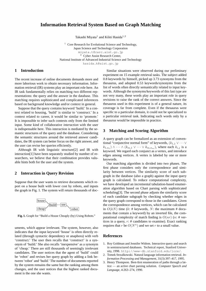
Information Retrieval System Based on Graph Matching
Takashi Miyata1 and Koiti Hasida1,2
1 Core Research for Evolutional Science and Technology,Japan Science and Technology Corporation
[email protected] Cyber Assist Research Center,
National Institute of Advanced Industrial Science and [email protected]
1 Introduction
The recent increase of online documents demands more andmore laborious work to obtain necessary information. Infor-mation retrieval (IR) systems play an important role here. AnIR task fundamentally relies on matching two different rep-resentations: the query and the answer in the database. Thismatching requires sophisticated and complicated inferencesbased on background knowledge and/or context in general.
Suppose that the query contains keyword ‘build.’ In a con-text related to housing, ‘build’ is similar to ‘construct.’ In acontext related to career, it would be similar to ‘promote.’It is impossible to infer such contexts only from the limitedinput. Some kind of collaborativeinteractionwith the useris indispensable here. This interaction is mediated by the se-mantic structures of the query and the database. Consideringthe semantic structures around the retrieved answer candi-dates, the IR system can better focus on the right answer, andthe user can revise her queries efficiently.
Although IR with linguistic structure[2] and IR withinteraction[1] have been separately studied by number of re-searchers, we believe that their combination provides valu-able hints both for the user and the system.
2 Interaction in Query Revision
Suppose that the user wants to retrieve documents which re-port on a house built with lower cost by robots, and inputsthe graph in Fig. 1. The system will return thousands of doc-
house
cheapbuild
��@@ use
robot@@
Fig. 1.Graph for “Build a House Cheaply (by) Using Robots.”
uments, which appear irrelevant. The system, however, alsoindicates that the input keyword ‘house’ is often directly re-lated (through syntactic dependency or anaphora) with verb‘construct.’ The user then recalls that ‘construct’ is a syn-onym of ‘build.’ She also recalls ‘inexpensive’ as a synonymof ‘cheap.’ There are still thousands of seemingly irrelevantcandidates. The user notices that the agent of ‘build’ couldbe ‘robot’ and revises her query graph by adding a link be-tween ‘robot’ and ‘build.’ The number of documents reportedby the system remains the same but the ranking among themchanges, and the user notices that the highest ranked docu-ment is the one she wants.
Similar situations were observed during our preliminaryexperiment on 15 example retrieval tasks. The subject added0.8 keywords by himself, picked up 3.73 synonyms from thethesaurus, and adopted 0.53 keywords/synonyms from thelist of words often directly semantically related to input key-words. Although the synonyms/keywords of this last type arenot very many, these words play an important role in queryrevisions to raise the rank of the correct answers. Since thethesaurus used in this experiment is of a general nature, itscoverage is far from complete. Even if the thesaurus werespecific to a particular domain, it could not be specialized toa particular retrieval task. Indicating such words only by athesaurus would be impossible in practice.
3 Matching and Scoring Algorithm
A query graph can be formalized as an extension of conven-tional “conjunctive normal form” of keywords,(k1,1 ∨ · · · ∨k1,n1) ∧ · · · ∧ (km,1 ∨ · · · ∨ km,nm), where eachki,j is akeyword. We regard each conjunct as a vertex, and introduceedges among vertices. A vertex is labeled by one or morekeywords.
Our matching algorithm is divided into two phases. Thefirst phase considers only the correspondence and simi-larity between vertices. The similarity score of each sub-graph in the database (also a graph) against the input querygraph is calculated. To reduce computational complexity,we have developed an incremental tabulation-based enumer-ation algorithm based on Chart parsing with sophisticatedscheduling[3]. The second phase adjusts the similarity scoreof each candidate subgraph by checking whether edges inthe query graph correspond to those in the candidates. Giventhe correspondence among vertices, which can be calculatedin O(kN) time (k: # keywords,N : the maximum # docu-ments that contain a keyword) by an inverted file, the com-putational complexity of match finding isO(nr) (n: # ver-tices in a query,r: # candidates to examine). Exact rankingrequires thatr beO(Nn) and we setr to a small value.
References
1. Roy Goldman and Jennifer Widom. Interactive query and searchin semistructured databases. Technical report, Stanford Univer-sity, 1998.http://www-db.stanford.edu/lore/ .
2. Tomek Strzalkowski. Natural language information retrieval.In-formation Processing and Management, 31(3):397–417, 1995.
3. Henry Thompson. Best-first enumeration of paths through a lat-tice — an active chart parsing solution.Computer Speech andLanguage, 4:263–274, 1990.

Formal Knowledge Management in Distributed Environments?
W. Marco Schorlemmer1, Stephen Potter1, David Robertson1, and Derek Sleeman2
1 CISA, Division of Informatics, The University of Edinburgh2 Department of Computing Science, University of Aberdeen
In order to address problems stemming from the dynamicnature of distributed systems, there is a need to be able toexpress notions of evolution and change of knowledge com-ponents of such systems. This need becomes more press-ing when one considers the potential of the Internet for dis-tributed knowledge-based problem solving — and the prag-matic issues surrounding knowledge integrity and trust thisraises. We introduce a formal calculus for describing trans-formations in the ‘lifecycles’ of knowledge components,along with suggestions about the nature of distributed en-vironments in which the notions underpinning the calculuscan be realised. The formality and level of abstraction of thislanguage encourages the analysis of knowledge histories andallows useful properties about this knowledge to be inferred.
Formal Lifecycles in a Brokering Architecture
We take the real-life example ofEcolingua3, an ontologyfor ecological meta-data. It was constructed on the Ontolin-gua Server4 by reusing classes from other ontologies in theserver’s library, and then automatically translated into Prologsyntax by the server’s translation service.
Fig. 1.Ecolingua’s lifecycle
Because the outcome of the translation process was anoverly large 5.3 Mb file, and in order to get a smaller andmore manageable set of axioms, it was necessary to reducethe ontology, by implementing filters that first deleted all ex-traneous clauses, and then pruned the class hierarchy and re-moved irrelevant clauses accordingly. Finally, a translation? Supported under the AKT IRC, which is sponsored by the UK
EPSRC under grant GR/N15764/01, and comprises the Univer-sities of Aberdeen, Edinburgh, Sheffield, Southampton and theOpen University.
3 Correa da Sliva et al.: On the insufficiency of ontologies: prob-lems in knowledge sharing and alternative solutions. Knowledge-Based Systems15 (2002) 147–167.
4 Farquhar, A., Fikes, R., Rice, J.: The Ontolingua Server: a toolfor collaborative ontology construction. International Journal ofHuman-Computer Studies46 (1997) 707–727.
into Horn clauses was performed in order to use the ontologywith a Prolog interpreter (see Figure 1).
We postulate that particular sequences of lifecycle stepslike those of Figure 1 might be common in particular do-mains and perhaps with particular forms of knowledge com-ponent. The ability to generalise and ‘compile’ these se-quences intolifecycle patternswould encourage more effi-cient behaviour when faced with the need to make similarmodifications in the future.
Fig. 2.EditingEcolingua’s lifecycle
For this reason we have implemented alifecycle editor andinterpreter that (1) enables a knowledge engineer to anal-yse the lifecycle of a knowledge component, extract its ab-stract pattern, and devise a formal representation of it (seeFigure 2), using rules of a formal lifecycle calculus that cap-ture abstract lifecycle steps such asweaken the ontologybymeans of a channel-theoretic semantics5; and (2) is capableof executing the formal representation of a lifecycle.
Since lifecycle patterns are described at a generic level, wehave implemented abrokering servicethat enacts the lifecy-cle execution in a distributed environment, so that a knowl-edge engineer can choose among several solvers capable ofperforming abstract lifecycle steps in a particular domain-specific fashion.
The lifecycle execution generates alifecycle historyof theknowledge component. This lifecycle history can later beused to infer properties of the components, not by inspect-ing the specification of the component itself — since thiswould require the cumbersome task of reasoning with theaxioms that constitute the specification — but by inspectingthe structure of its lifecycle.
5 Barwise, J., Seligman, J.: Information Flow: The Logic of Dis-tributed Systems. Cambridge University Press (1997).

Distributed Semantic Perspectives
Oliver Hoffmann and Markus Stumptner
University of South Australia([email protected],[email protected])
1 Introduction
With increased use of domain ontologies arises the task ofcombining or linking existing ontologies. But in general, ex-isting ontologies are based on different semantic contexts andtherefore simple merging of two or more existing ontologiesis not feasible: symbols in one ontology might have little orno congruency with symbols in another ontology; thereforesemantic context has to be reconstructed from within avail-able data [1] or via intervention from outside the computersystem. In this paper, a concept for re-construction of con-text and re-interpretation of knowledge on the basis of exter-nal user input is presented.
2 Non-Implementables
The semantics of a symbol can be described as a triangularrelationship between the symbol itself, the entity referred toby the symbol and the concept some individual has of thatentity [2].
individual concept of graduate student
GraduateStudent
Fig. 1. the semantic triangle
Figure 1 shows a semantic triangle for the symbol Grad-uateStudent: The symbol is set into relation with a graduatestudent (real world entity, bottom left) and the concept ofgraduate student as conceived by some individual (top). Twoof the three elements required for a semantic relationship(individual concept and real world entity) cannot be imple-mented in a computer system: A computer system can hold areference to real world entities or concepts of real world en-tities, but such references would have to be symbols and assuch only have semantic content when itself set in relation toentities and concepts outside of the computer system. Thusnon-implementables(nimps) are necessary and irreplaceablepreconditions for semantic content.
3 Standardized Interpretation
Although nimps are not directly accessible, knowledge en-gineering can influence nimps indirectly. For instance, indi-vidual concepts can be synchronized via the use of shared
symbols. Formal semantics of data contained in ontologiesfacilitate compatible interpretation of new symbols on the ba-sis of symbols already interpreted in a compatible way. Thusa standardized interpretation of symbols is developed, or a“world 3” as described by Karl Popper: In addition to theworld of real entities (“world 1”) and the concepts some in-dividual has about the world (“world 2”), a third world ofshared interpretations is built among some group of indi-viduals with the help of symbols. But according to Popper,this standardization process has to be open ended [3] if thestandards used are to serve a purpose like that envisioned inthe semantic web initiative [4]. It has to remain possible tore-define standards and to re-interpret standards in differentcontexts. For example, the term “graduate student” is ill de-fined in a standard German University context, because ofsignificant differences in University education structure. Ifthe symbol GraduateStudent in some ontology is interpretedas referring to the level of expertise, then the number ofsemesters of prior study can be the appropriate translation. IfGraduateStudent is interpreted as referring to the formal de-gree, then some adequate degree like “Diplom-Informatiker”might be the corresponding title. Thus implicitly standard-ized nimps associated with ontologies have to be taken intoconsideration when combining different ontologies.
4 Semantic Perspectives
The concept of semantic perspectives is a generalization ofdesign perspectives [5]. Distributed semantic perspectivesare ontologies loosely linked via plug-and-play translatorsand constitute different views on a common content., thuscreating a distributed system of different perspectives on thecommon semantic content. In the case of a single seman-tic perspective without links to other perspectives, the nimpparts of it’s semantic content can be assumed to be suffi-ciently standardized: Either the nimp parts of its semanticcontent are completely identical among different individu-als interacting with the perspective or nimp differences arecompatible with the perspective’s intended functionality. Ifperspectives are to be combined, however, nimp differenceshave to be considered. A specific translator between twogiven perspectives operates context-less in the sense that itonly operates on symbols, which can be interpreted as ei-ther ignoring nimp parts of semantic content or implicitlyassuming a standardized semantic context for the transla-tion. Therefore any automated choice of translator as in [6]is equivalent to restricting nimp parts of semantic content toone specific semantic context. In order to accomodate differ-ent contexts, translators between semantic perspectives canbe turned on and off at run time and two given perspectivescan be linked by any of a set of alternative translators, witheach translator implicitly determining semantic context forboth the source and target perspective.

Distributed Semantic Perspectives 113
Fig. 2.external choice of translator
This dynamic re-combination of translators and per-spectives (Figure 2), allows for re-interpretation and re-contextualization of semantic content, thus accomodatingchanging contexts. Distributed semantic perspectives can belinked and thus several ontologies can be combined, editedand used in parallel. In contrast, one final merging operationlike in [7] would eliminate the option of re-interpreting con-text for source perspectives and limit interpretation for themerged result perspective.
Semantic perspectives have been implemented via the in-tegration of the Java Agent Development Environment JADE[8] 1, a multi agent system, the Java Expert System ShellJESS [9]2, a rule based language, Protege-2000 [10]3, an on-tology editor, the JessTab [11] a plugin for Protege-2000, andJadeJessProtege4. Two types of features are added to stan-dard ontology editor features: First, the ability to extract andintegrate ontological information from and into the runningontology editor; second, the ability to transmit and receivesuch ontological information to and from translators into orfrom other ontology editors. With these additional features,the ontology editor is turned into an agent. Perspectives andtranslators, which can be hosted on different computers, reg-ister with a JADE platform. Once a semantic perspective hasestablished contact with the JADE agent platform and re-ceived a list of relevant translators, parts of the ontology can
1 http://jade.cselt.it2 http://herzberg.ca.sandia.gov/jess3 http://protege.stanford.edu4 http://JadeJessProtege.net
be extracted and sent to translators via JADE agent messages.Then translators re-contextualize content as illustrated by thefollowing JESS code:
(Information (Perspective Ontology1) (Class Student) (SlotName) (Value ?name))(Information (Perspective Ontology1) (Class Matura) (SlotName) (Value ?name))(Information (Perspective Ontology1) (Class Matura) (SlotYear) (Value ?year))(test (< ?year 1998))=>(assert (Information (Perspective Ontology2) (Class Gradu-ateStudent) (Slot Name)(Value ?name)))
In this example, information extracted from the sourceperspective Ontology1 is translated into information for thetarget perspective Ontology2. The source perspective con-tains information that a student with some name has passedMatura (high school graduation) before 1998. This is trans-lated into the information that the student is a graduate stu-dent. Here the number of years passed since some personcame out of high school is used as an (imperfect) indicatorof whether a student should be regarded as “graduate” stu-dent in a specific context.
References
1. Stuckenschmidt, H., Visser, U.: Semantic Translation basedon Approximate Re-Classification. In: Proceedings of theWorkshop “Semantic Approximation, Granularity and Vague-ness”, Proc. KR2000, San Francisco, California, U.S.A., Mor-gan Kaufmann (2000)
2. Sowa, J.: Knowledge Representation: Logical, Philosophicaland Computational Foundations. Brooks/Cole, Pacific Grove,California, U.S.A (2000)
3. Popper, K.: Objective Knowledge: An Evolutionary Approach.Oxford University Press, Oxford, U.K. (1972)
4. Berners-Lee, T., Hendler, J., Lassila, O.: The Semantic Web.Scientific American (2001)
5. Hoffmann, O., M.Stumptner, Chalabi, T.: Tolerating Incon-sistencies: The Distributed Perspectives Model. In: ComputerAided Architectural Design Futures, Dortrecht, N.L., Kluwer(2001) 375–386
6. Campbell, A.E., Shapiro, S.: Algorithms for Ontological Me-diation. Technical report, Dep. of CS and Engineering, StateUniv. of New York at Buffalo (1998)
7. McGuinness, D.L., Fikes, R., Rice, J., Wilder, S.: An Envi-ronment for Merging and Testing Large Ontologies. In: Proc.KR2000, Breckenridge, Colorado, U.S.A. (2000)
8. Bellifemine, F., Poggi, A., Rimassa, G.: JADE – a FIPA-compliant agent framework. In: Fourth International Confer-ence on the Practical Application of Intelligent Agents andMulti-Agent Technology(ATCS). (1999) 97–108
9. Friedmann-Hill, E.: Jess, the java expert system shell. Tech-nical report, Sandia National Laboratories, Livermore, CA,U.S.A. (1998)
10. Noy, N.F., Sintek, M., Decker, S., Crubezy, M., Fergerson,R.W., Musen, M.A.: Creating Semantic Web Contents withProtege-2000. IEEE Intelligent Systems2 (2001)
11. Eriksson, H.: The JessTab Approach to Protege and JESS Inte-gration. In: Intelligent Information Processing IIP-2002, Mon-treal, Canada (2002)

A framework to solve the ontology translation problem
Oscar Corcho
Facultad de Informatica. Universidad Politecnica de MadridCampus de Montegancedo, s/n. 28660 Boadilla del Monte. Madrid. Spain
Abstract. Ontologies are developed with differenttools and languages. Reusing an ontology usuallyrequires transforming it from its original formatto a target format. However, many problems usu-ally arise in these transformations, related to thecompatibility among tools/languages. We proposean ontology reengineering methodology (with itstechnological support) as a solution to the ontologytranslation problem.
1 Introduction
Nowadays, different tools exist for developing ontologies:OILEd, OntoEdit, Ontolingua, OntoSaurus, Protege2000,WebODE, WebOnto, etc. Each tool has their own knowledgemodel, and usually allows exporting/importing ontologies intheir own textual representation.
Several languages are also used for the implementationof ontologies, such as Ontolingua, LOOM, OCML, FLogic,XOL, SHOE, RDF(S), OIL, DAML+OIL, etc. Apart fromtheir lexical and syntactical differences, there are also moresignificant ones due to the knowledge representation (KR)formalism in which they are based (frames, semantic nets,description logic, etc.) and the semantics of their represen-tation primitives and constructs, which fully determine boththeir expressiveness and reasoning capabilities.
The ontology translation problem appears when we decideto reuse an ontology (or part of an ontology) using a toolor language that is different from those ones in which theontology is available. If we force each ontology developer,individually, to commit to the task of translating and incor-porating the necessary ontologies to their systems, they willneed both a lot of effort and a lot of time to achieve their ob-jectives. Therefore, ontology reuse in different contexts willbe highly boosted as long as we provide automatic ontologytranslation services among those languages and/or tools.
2 Characterisation of the ontology translationproblem
The first reference to this problem was presented by Gruberin [2]. He proposed, as a solution, to follow a set ofonto-logical commitmentswhen an ontology was created. Fromall these ontological commitments, the ”minimal encodingbias” deserves special attention: Gruber proposed to concep-tualise ontologies in the knowledge level, instead of doingit in the symbolic level, and to implement them using auto-matic translators. However, this criterion has not been com-monly followed in ontology development, forcing ontologydevelopers to translate existing ontologies manually or createad-hoc translators between languages or knowledge models,which is a time consuming task.
Translation problems can be classified as follows:Lexical problems. They appear when the terms used for
language identifiers, texts and constructs (names of compo-nents, sizes of their textual descriptions, etc.) follow differentconventions in the different languages and/or tools. For in-stance, concept National Park in Ontolingua is usually writ-ten asNational-Park, while in FLogic hyphens are not al-lowed inside identifiers (hence, it is written asNationalPark).
Syntax problems. Different languages/tools use differ-ent grammars to represent their components. Some lan-guages/tools also allow defining the same component in dif-ferent ways. When performing translations, both situationsmust be taken into account.
Expressiveness problems. These problems are caused be-cause different languages/tools are based on different KRparadigms. First, not all the languages allow expressing thesame knowledge: we must analyse what components can betranslated directly from a language to another one, what com-ponents can be expressed using other components from thetarget language, what components cannot be expressed in thetarget language, and what components can be expressed, al-though with losses of expressiveness.
Reasoning problems. The existence or not of an inferenceengine for a language, and the characteristics of this infer-ence engine, usually bias the implementation of an ontology.
3 The framework: WebODE and OntoDialect
We propose to solve the translation problem in the context ofa methodology for ontological reengineering. We distinguishthree main phases:reverse engineering(we transform auto-matically an ontology that has been coded in a language toa knowledge model that is independent from the implemen-tation); reestructuration(performed in the knowledge level,in accordance to the future uses of the ontology in an appli-cation); andimplementation(we transform automatically thereestructured ontology into the target language).
This methodology is technologically supported by the We-bODE ontology-engineering workbench [1]. Reestructura-tion is currently performed manually, with the WebODE on-tology editor. Translators from WebODE to ontology lan-guages/tools and vice versa can be created with the Onto-Dialect system, integrated in the workbench.
References
1. Arpırez JC, Corcho O, Fernandez-Lopez M, Gomez-PerezA. WebODE: a scalable workbench for ontological engineer-ing. First International Conference on Knowledge Capture(KCAP2001). Victoria. Canada. October, 2001.
2. Gruber R. A translation approach to portable ontology specifica-tion Knowledge Acquisition. #5: 199-220. 1993

Author Index
Bowers, Shawn 19
Casati, Fabio 1Castano, Silvana 51Chu, Wesley W. 3Corcho, Oscar 114
Delcambre, Lois 19Dell’Erba, Mirella 69
Euzenat, Jerome 93
Fan, Hao 36Felfernig, Alexander 11Ferrara, Alfio 51Fodor, Oliver 69Friedrich, Gerhard 11
Hasida, Koiti 110Hoffmann, Oliver 112
Jannach, Dietmar 11
Kiryakov, Atanas 27
Lee, Dongwon 3
Maedche, Alexander 60Mani, Murali 3
Mitra, Prasenjit 43Miyata, Takashi 110Motik, Boris 60
Ognyanov, Damyan 27Omelayenko, Borys 77
Peer, Joachim 101Potter, Stephen 85, 111Poulovassilis, Alexandra 36
Ricci, Francesco 69Robertson, Dave 85Robertson, David 111
Schorlemmer, W. Marco 85, 111Silva, Nuno 60Sleeman, Derek 85, 111Spada, Antonella 69Stuckenschmidt, Heiner 93Stumptner, Markus 11, 112
Volz, Raphael 60
Werthner, Hannes 69Wiederhold, Gio 43
Zanker, Markus 11