Proceedings of the Linux Symposium - Kernel
320
Proceedings of the Linux Symposium Volume Two July 20nd–23th, 2005 Ottawa, Ontario Canada
Transcript of Proceedings of the Linux Symposium - Kernel

Proceedings of theLinux Symposium
Volume Two
July 20nd–23th, 2005Ottawa, Ontario
Canada


Contents
PCI Express Port Bus Driver Support for Linux 1T.L. Nguyen, D.L. Sy, & S. Carbonari
pktgen the linux packet generator 11Robert Olsson
TWIN : A Window System for ‘Sub-PDA’ Devices 25K. Packard
RapidIO for Linux 35Matt Porter
Locating System Problems Using Dynamic Instrumentation 49V. Prasad, W. Cohen, F. Ch. Eigler, M. Hunt, J. Keniston, & B. Chen
Xen 3.0 and the Art of Virtualization 65I. Pratt, Fraser, Hand, Limpach, Warfield, Magenheimer, Nakajima, & Mallick
Examining Linux 2.6 Page-Cache Performance 79S. Rao, D. Heger, & S. Pratt
Trusted Computing and Linux 91K. Hall, T. Lendacky, E. Ratliff, & K. Yoder
NPTL Stabilization Project 111S. Decugis & T. Reix
Networking Driver Performance and Measurement - e1000 A Case Study 133J.A. Ronciak, J. Brandeburg, G. Venkatesan, & M. Willams
nfsim: Untested code is buggy code 141R. Russell & J. Kerr

Hotplug Memory Redux 151Schopp, Hansen, Kravetz, Hirokazu, Iwamoto, Yasunori, Kamezawa, Tolentino, & Picco
Enhancements to Linux I/O Scheduling 175S. Seelam, R. Romero, P. Teller, & B. Buros
Chip Multi Processing aware Linux Kernel Scheduler 193S. Siddha, V. Pallipadi, & A. Mallick
SeqHoundRWeb.py: interface to a comprehensive online bioinformatics resource 205Peter St. Onge
Ho Hum, Yet Another Memory Allocator. . . 209Ravikiran G. Thirumalai
Beagle: Free and Open Desktop Search 219Jon Trowbridge
Glen or Glenda 221Eric Van Hensbergen
LINUX R© Virtualization on Virtual Iron TM VFe 235A. Vasilevsky, D. Lively, & S. Ofsthun
Clusterproc: Linux Kernel Support for Clusterwide Process Management 251B.J. Walker, L. Ramirez, & J.L. Byrne
Flow-based network accounting with Linux 265Harald Welte
Introduction to the InfiniBand Core Software 271Bob Woodruff
Linux Is Now IPv6 Ready 283Hideaki Yoshifuji

The usbmon: USB monitoring framework 291Pete Zaitcev
Adopting and Commenting the Old Kernel Source Code for Education 297Jiong Zhao


Conference Organizers
Andrew J. Hutton,Steamballoon, Inc.C. Craig Ross,Linux SymposiumStephanie Donovan,Linux Symposium
Review Committee
Gerrit Huizenga,IBMMatthew Wilcox,HPDirk Hohndel,IntelVal Henson,Sun MicrosystemsJamal Hadi Salimi,ZnyxMatt Domsch,DellAndrew Hutton,Steamballoon, Inc.
Proceedings Formatting Team
John W. Lockhart,Red Hat, Inc.
Authors retain copyright to all submitted papers, but have granted unlimited redistribution rightsto all as a condition of submission.


PCI Express Port Bus Driver Support for Linux
Tom Long Nguyen, Dely L. Sy, & Steven CarbonariIntel R© Corporation∗
{tom.l.nguyen, dely.l.sy, steven.carbonari}@intel.com
Abstract
PCI ExpressR©1 is a high performance gen-eral purpose I/O Interconnect defined for awide variety of computing and communicationplatforms. It defines PCI Express Ports andswitches to provide a fabric based point-to-point topology. PCI Express categorizes PCIExpress Ports into three types: the Root Ports,the Switch Upstream Ports, and the SwitchDownstream Ports. Each PCI Express Portcan provide up to four distinct services: na-tive hot-plug, power management, advanced er-ror reporting, and virtual channels[1][3]. Tofit within the existing LinuxR©2 PCI DriverModel but provide a clean and modular solu-tion, in which each service driver can be builtand loaded independently, requires the PCI Ex-press Port Bus Driver architecture. The PCI Ex-press Port Bus Driver initializes all services anddistributes them to their corresponding servicedrivers. This paper is targeted toward kerneldevelopers and architects interested in the de-tails of enabling service drivers for PCI ExpressPorts. The i386 Linux implementation will beused as a reference model to provide insightinto the implementation of the PCI Express
∗Intel is a trademark or registered trademark of IntelCorporation in the United States, other countries, or both.This work represents the view of the authors and does notnecessarily represent the view of Intel.
1PCI Express is a trademark of the Peripheral Com-ponent Interchange Special Interest Group (PCI-SIG)
2Linux is a registered trademark of Linus Torvalds
Port Bus Driver and specific service drivers likethe advanced error reporting root service driverand the native hot-plug root service driver.
1 Introduction
The Linux PCI Driver Model restricts a deviceto a single driver. Drivers in Linux are loadedbased off the PCI Device ID and function. Oncea driver is loaded, no other drivers for that de-vice can be loaded[2]. Referring to Figure 1,if the Root Port hot-plug driver is loaded first,it claims the Root Port device. The Linux PCIDriver Model therefore prevents the support ofmultiple services per PCI Express Port usingindividual service drivers.
Figure 1: Service Drivers under the Linux PCIDriver Model
A PCI Express Port may have multiple distinctservices operating independently. A PCI Ex-press Port is not required to support all ser-vices, so some PCI Express Ports within a PCIExpress hierarchy may support none, some orall the services. A possible solution is to im-plement a single driver to handle all services
• 1 •

2 • PCI Express Port Bus Driver Support for Linux
per PCI Express Port. However, this solutionwould lack the ability to have each service builtand loaded independently from each other, pre-venting extensibility for addition of future ser-vices and the ability to have a service driverloaded on more than one PCI Express Port.Separate service drivers are required to supportaddition of new features and loading of servicesbased on the PCI Express Port capabilities.
To support multiple drivers per device withoutchanging the existing Linux PCI Driver Modelrequires a new architecture that fits withinthe existing Linux PCI Driver Model but pro-vides the flexibility required to support multi-ple service drivers per PCI Express Port. Asshown in Figure 2, the PCI Express Port BusDriver (PBD)[5] fits into the existing Linux PCIDriver Model while providing an interface toallow multiple independent service drivers tobe loaded for a single PCI Express Root Port.The PBD acts as a service manager that ownsall services implemented by the Ports. Each ofthese services is then distributed and handledby a unique service driver. The PBD achievesthe following key advantages:
• Allows multiple service drivers to runsimultaneously and independently fromeach other and to service more than onePCI Express Port.
• Allows service drivers to be designed andimplemented in a modular fashion.
• Centralizes management and distributionof resources of the PCI Express Port de-vices to requested service drivers.
This paper describes the PCI Express Port BusDriver architecture. Following the port busdriver architecture are two examples of servicedrivers. The first example is the advanced er-ror reporting service driver that was designed to
Figure 2: Service Drivers under the PBD
work with the port bus architecture. The secondexample is the hot-plug service driver that wasoriginally designed as an independent driverthen converted to a service driver to operatewith the Port Bus Driver. Lastly, an overviewof the impact to device drivers and future ser-vice drivers is outlined.
2 PCI Express Port Bus Driver
2.1 PCI Express Port Topology
To understand the Port Bus Driver architecture,it helps to begin with the basics of PCI ExpressPort topology. Figure 3 illustrates two types ofPCI Express Port devices: the Root Port andthe Switch Port. The Root Port originates aPCI Express Link from a PCI Express RootComplex. The Switch Port, which has its sec-ondary bus representing switch internal rout-ing logic, is called the Switch Upstream Port.The Switch Port which is bridging from switchinternal routing buses to the bus representingthe downstream PCI Express Link is called theSwitch Downstream Port[1].
Each PCI Express Port device can be imple-mented to support up to four distinct services:native hot plug (HP), power management event(PME), advanced error reporting (AER), virtualchannels (VC). The PCI Express services dis-cussed are optional, so in any given PCI Ex-press hierarchy a port may support none, some,or all of the services.

2005 Linux Symposium • 3
Figure 3: PCI Express Port Topology
2.2 PCI Express Port Bus Driver Architec-ture
The design of the PCI Express Port Bus Driverachieves a clean and modular solution in whicheach service driver can be built and loaded in-dependently from each other. The PCI ExpressPort Bus Driver serves as a service managerthat loads and unloads the service drivers ac-cordingly, as illustrated in Figure 4.
Figure 4: PCI Express Port Bus Driver SystemView
The PCI Express Port Bus Driver is a PCI-PCI Bridge device driver, which attaches to PCIExpress Port devices. For each PCI ExpressPort device, the PCI Express Port Bus Driversearches for all possible services, such as na-tive HP, PME, AER, and VC, implemented byPCI Express Port device. For each service
found, the PCI Express Port Bus Driver createsa corresponding service device, named pcieXYwhere X indicates the PCI Express Port typeand Y indicates the PCI Express service typeas described in Table 1, and then registers thisservice device into a system device hierarchy.Figure 5 shows an example of how the PCI Ex-press Port Bus Driver creates service deviceson a system populated with two Root Port de-vices, one Switch Upstream Port device, andtwo Switch Downstream Port devices.
Port Service Service Entity Description (pcieXY)Type Type(X) (Y)0 0 PME service on PCI Express Root Port (PMErs)0 1 AER service on PCI Express Root Port (AERrs)0 2 HP service on PCI Express Root Port (HPrs)0 3 VC service on PCI Express Root Port (VCrs)1 0 PME service on PCI Express Switch Upstream Port (PMEus)1 1 AER service on PCI Express Switch Upstream Port (AERus)1 2 Not a supported PCI Express configuration1 3 VC service on PCI Express Switch Upstream Port (VCus)2 0 PME service on PCI Express Switch Downstream Port (PMEds)2 1 AER service on PCI Express Switch Downstream Port (AERds)2 2 HP service on PCI Express Switch Downstream Port (HPds)2 3 VC service on PCI Express Switch Downstream Port (VCds)
Table 1: Service Entity Description
Figure 5: Service Devices in a PCI Express PortBus Driver Architecture
Once service devices are discovered and addedin the system device hierarchy, a service driveris loaded accordingly if it registers its ser-vice with the PCI Express Port Bus Driver.The PCI Express Port Bus Driver providesan interface, namedpcie_port_service_register , to allow a service driver to registerits service[4]. The registration enables the user

4 • PCI Express Port Bus Driver Support for Linux
to configure services during kernel configura-tion regardless of HW support. It enables de-bugging and adding of new services in a modu-lar fashion. When a service driver callspcie_port_service_register , the PCI Ex-press Port Bus Driver loads a service driverby invoking the PCI subsystem, which walksthrough a system device hierarchy for a servicematch. If the port bus finds a match, it loads aservice driver for that service device.
In addition, the PCI Express Port BusDriver provides pcie_port_service_
unregister , to undo the effects of callingfunction pcie_port_service_register
[4]. Note that a service driver should alwayscall pcie_port_service_unregister
when a service driver is unloading.
2.3 The Service Driver
To maintain modularity in the PCI Express PortBus Driver design, individual service driversare required. In some cases a driver may al-ready exist for a PCI Express Port. In these in-stances the driver must be ported to the servicedriver to allow other service drivers to load onthe PCI Express Port. To port drivers to servicedrivers, the following three basic steps are re-quired. Refer to Sections 3.1.1 to 3.1.3 for aspecific example.
• Specify service ID. The PCI Express PortBus Driver defines the data structure ofservice ID similar to the data structureof pci_device_id except with twoadditional fields: theport_type andservice_type fields as described inTable 1. Note that failure to specify a cor-rect service ID will prevent the port busfrom loading a service driver.
• Initialize service driver. The PCI ExpressPort Bus Driver defines the data struc-ture of service driver similar to thepci_
driver data structure. The pointer to thepci_dev data structure is replaced with apointer to thepcie_device data struc-ture in each callback function.
• Call pcie_port_service_register
insteadpci_register_driver .
Once a service driver is loaded, a service drivershould always configure and initialize its owncapability structure and required IOs to oper-ate normally without any support from the PCIExpress Port Bus Driver. However, a servicedriver is prohibited from doing the following:
• Switch the interrupt mode on a device.The interrupt mode can be INTx legacy,MSI or MSI-X. A service driver should al-ways use the assigned service IRQ to callrequest_irq to have its software in-terrupt service routine hookup. Note thatthe assigned service IRQ may be sharedamong service drivers; therefore, a servicedriver should always treat this assignedservice IRQ as shared interrupt.
• Access resources that are not directly re-quired by the service. For example, theadvanced error reporting service driver isprohibited from accessing any configura-tion registers other than the Advanced Er-ror Reporting Capability structure. A ser-vice driver uses theport pointer, a mem-ber of thepcie_device data structuredefined by PBD, to access PCI configura-tion and memory mapped IO space.
• Call pci_enable_device and pci_set_master functions. This is nolonger necessary because these functionsnow get called by the PCI Express PortBus Driver.

2005 Linux Symposium • 5
2.4 Resource Allocation and Distribution
Service drivers must adhere to the guidelines inthis document to deal with resource allocationand distribution. Since all service drivers of aPCI Express Port device are allowed to run si-multaneously, a decision of which driver (PortBus Driver vs. service driver) owns which re-source is described in Sections 2.4.1 to 2.4.3.These resources include the MSI capabilitystructure, the MSI-X capability structure, andPCI IO resources.
2.4.1 The MSI Capability Structure
The MSI capability structure enables a devicesoftware driver to callpci_enable_msi torequest an MSI based interrupt. Once MSI isenabled on a device, it stays in this mode un-til a device driver callspci_disable_msito return to INTx emulation. Since each ser-vice driver runs independently from each other,changing the interrupt mode on the PCI Ex-press Port by an individual service driver mayresult in unpredictable behavior. Each ser-vice driver is therefore prohibited from call-ing these APIs. The PCI Express Port BusDriver is responsible for determining the in-terrupt mode and assigning the service IRQto each service device accordingly. A servicedriver must use its service vector when callingrequest_irq /free_irq .
2.4.2 The MSI-X Capability Structure
Similar to MSI a device driver for an MSI-X ca-pable device can callpci_enable_msix torequest MSI-X interrupts. The key differenceis that the MSI-X capability structure enablesa PCI Express Port device to generate multi-ple messages. Managing multiple MSI-X vec-tors is handled by the PCI Express Port Bus
driver. The PCI Express Port Bus Driver is re-sponsible for determining the interrupt modetransparent to the service drivers. A servicedriver must use its service vector when callingrequest_irq /free_irq .
If a PCI Express Port device supports MSI-X,the PCI Express Port Bus Driver will requestthe number of MSI-X messages equal to thenumber of supported services for the device.This allows each service to have it own hard-ware interrupt resource independently gener-ated from other services.
2.4.3 PCI IO Resources
PCI IO resources include PCI memory/IOranges and PCI configuration registers are as-signed by BIOS during boot. For PCI mem-ory/IO ranges, the service driver is responsiblefor initializing its PCI memory/IO maps duringservice startup. There is possibly where the PCImemory/IO ranges are shared. If this occurs,each service driver is responsible for mappingits PCI memory/IO regions without overstep-ping on resources of others. The PCI ExpressPort Bus Driver does not arbitrate access to theregions and assumes service drivers to be wellbehaved.
For PCI configuration registers, each serviceruns PCI configuration operation on its own ca-pability structure except the PCI Express ca-pability structure, in which the Device Con-trol register and the Root Control register haveunique control bits assigned to AER serviceand PME service. A read-modify-write shouldalways be handled by the AER/PME servicedriver. Again this paper assumes that all servicedrivers are responsible for not overstepping onresources of others.
6 • PCI Express Port Bus Driver Support for Linux
3 PCI Express Advanced Error Re-porting Root Service Driver
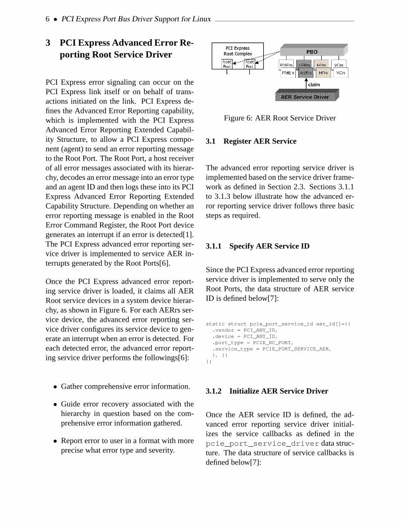
PCI Express error signaling can occur on thePCI Express link itself or on behalf of trans-actions initiated on the link. PCI Express de-fines the Advanced Error Reporting capability,which is implemented with the PCI ExpressAdvanced Error Reporting Extended Capabil-ity Structure, to allow a PCI Express compo-nent (agent) to send an error reporting messageto the Root Port. The Root Port, a host receiverof all error messages associated with its hierar-chy, decodes an error message into an error typeand an agent ID and then logs these into its PCIExpress Advanced Error Reporting ExtendedCapability Structure. Depending on whether anerror reporting message is enabled in the RootError Command Register, the Root Port devicegenerates an interrupt if an error is detected[1].The PCI Express advanced error reporting ser-vice driver is implemented to service AER in-terrupts generated by the Root Ports[6].
Once the PCI Express advanced error report-ing service driver is loaded, it claims all AERRoot service devices in a system device hierar-chy, as shown in Figure 6. For each AERrs ser-vice device, the advanced error reporting ser-vice driver configures its service device to gen-erate an interrupt when an error is detected. Foreach detected error, the advanced error report-ing service driver performs the followings[6]:
• Gather comprehensive error information.
• Guide error recovery associated with thehierarchy in question based on the com-prehensive error information gathered.
• Report error to user in a format with moreprecise what error type and severity.
Figure 6: AER Root Service Driver
3.1 Register AER Service
The advanced error reporting service driver isimplemented based on the service driver frame-work as defined in Section 2.3. Sections 3.1.1to 3.1.3 below illustrate how the advanced er-ror reporting service driver follows three basicsteps as required.
3.1.1 Specify AER Service ID
Since the PCI Express advanced error reportingservice driver is implemented to serve only theRoot Ports, the data structure of AER serviceID is defined below[7]:
static struct pcie_port_service_id aer_id[]={{.vendor = PCI_ANY_ID,.device = PCI_ANY_ID,.port_type = PCIE_RC_PORT,.service_type = PCIE_PORT_SERVICE_AER,}, {}
};
3.1.2 Initialize AER Service Driver
Once the AER service ID is defined, the ad-vanced error reporting service driver initial-izes the service callbacks as defined in thepcie_port_service_driver data struc-ture. The data structure of service callbacks isdefined below[7]:

2005 Linux Symposium • 7
static struct pcie_port_service_driver aerdrv={.name = "aer",.id_table = &aer_id[0],
.probe = aer_probe,
.remove = aer_remove,
.suspend = aer_suspend,
.resume = aer_resume,};
3.1.3 Calling pcie_port_service_register
The final step in initialization of the advancederror reporting service driver is calling func-tion pcie_port_service_register to reg-ister AER service with the PBD. During driverinitialization, the module routine is called forinitialization when the kernel calls the ad-vanced error reporting service driver. Call-ing pcie_port_service_register /pcie_
port_service_unregister should alwaysbe done inmodule_init /module_exit asdepicted below[7]:
static int __init aer_service_init(void){
return pcie_port_service_register(&aerdrv);}
static void __exit aer_service_exit(void){
pcie_port_service_unregister(&aerdrv);}
module_init(aer_service_init);module_exit(aer_service_exit);
Figure 7 depicts the state diagram once the ad-vanced error reporting service driver’s moduleroutine is called.
4 PCI Express Native Hot-PlugService Driver
The PCI Express Hot-Plug standard usagemodel is derived from the standard usage
Figure 7: State Diagram of Registering AERService with PBD
model defined in the PCI Standard Hot-PlugController and Subsystem Specification, Rev.1.0[8].
4.1 PCI Express Native Hot Plug Features
PCI Express Native Hot-Plug features are:
• Root ports and downstream ports ofswitches are hot-pluggable ports in PCIExpress hierarchy.
• Interrupt driven hot plug events will resultin hot-plug interrupts.
• Hot plug registers are part of the PCI Ex-press Capability register set; hot-plug op-erations are invoked by writing to theseregisters.
• Based on SHPC usage model, but not thebus centric SHPC register set.
4.2 Porting the PCI Express Hot-PlugDriver to a Service Driver
As mentioned in Section 2.2, the PCI ExpressPort Bus Driver provides a mechanism for a
8 • PCI Express Port Bus Driver Support for Linux
service driver to register its service. If the re-quested service is found in a service devicehierarchy, the service driver can successfullyload. This section focuses on showing what thechanges are required to port the PCI Expressnative hot-plug driver to a service driver.
4.2.1 Registering the Hot Plug ServiceDriver
The pciehp driver calls pcie_port_
service_register (struct pcie_
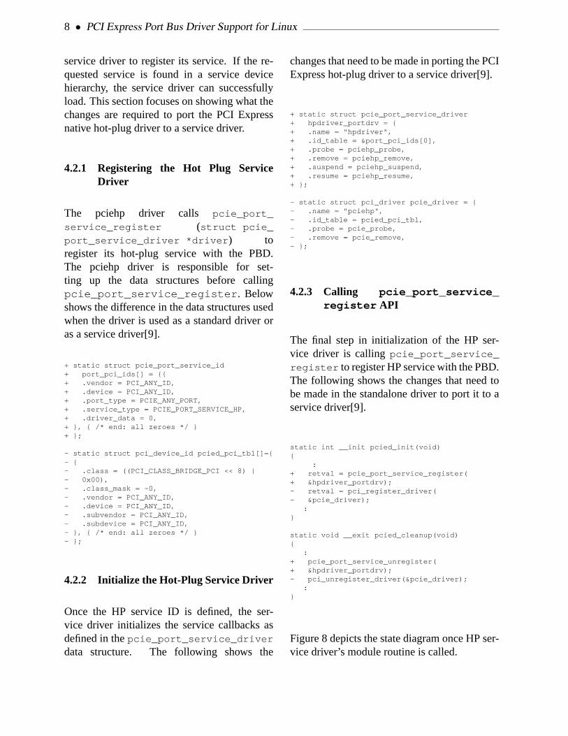
port_service_driver *driver ) toregister its hot-plug service with the PBD.The pciehp driver is responsible for set-ting up the data structures before callingpcie_port_service_register . Belowshows the difference in the data structures usedwhen the driver is used as a standard driver oras a service driver[9].
+ static struct pcie_port_service_id+ port_pci_ids[] = {{+ .vendor = PCI_ANY_ID,+ .device = PCI_ANY_ID,+ .port_type = PCIE_ANY_PORT,+ .service_type = PCIE_PORT_SERVICE_HP,+ .driver_data = 0,+ }, { /* end: all zeroes */ }+ };
- static struct pci_device_id pcied_pci_tbl[]={- {- .class = ((PCI_CLASS_BRIDGE_PCI << 8) |- 0x00),- .class_mask = ~0,- .vendor = PCI_ANY_ID,- .device = PCI_ANY_ID,- .subvendor = PCI_ANY_ID,- .subdevice = PCI_ANY_ID,- }, { /* end: all zeroes */ }- };
4.2.2 Initialize the Hot-Plug Service Driver
Once the HP service ID is defined, the ser-vice driver initializes the service callbacks asdefined in thepcie_port_service_driver
data structure. The following shows the
changes that need to be made in porting the PCIExpress hot-plug driver to a service driver[9].
+ static struct pcie_port_service_driver+ hpdriver_portdrv = {+ .name = "hpdriver",+ .id_table = &port_pci_ids[0],+ .probe = pciehp_probe,+ .remove = pciehp_remove,+ .suspend = pciehp_suspend,+ .resume = pciehp_resume,+ };
- static struct pci_driver pcie_driver = {- .name = "pciehp",- .id_table = pcied_pci_tbl,- .probe = pcie_probe,- .remove = pcie_remove,- };
4.2.3 Calling pcie_port_service_register API
The final step in initialization of the HP ser-vice driver is callingpcie_port_service_
register to register HP service with the PBD.The following shows the changes that need tobe made in the standalone driver to port it to aservice driver[9].
static int __init pcied_init(void){
:+ retval = pcie_port_service_register(+ &hpdriver_portdrv);- retval = pci_register_driver(- &pcie_driver);
:}
static void __exit pcied_cleanup(void){
:+ pcie_port_service_unregister(+ &hpdriver_portdrv);- pci_unregister_driver(&pcie_driver);
:}
Figure 8 depicts the state diagram once HP ser-vice driver’s module routine is called.

2005 Linux Symposium • 9
Figure 8: State Diagram of Registering HP Ser-vice with PBD
4.2.4 Available Resources
As a service driver, dev->irq is provided by thePCI Express Port Bus Driver and is passed tothe pciehp driver. Whether dev->irq is a reg-ular system interrupt, MSI or MSI-X, the PCIExpress Port Bus Driver assigns the value toit. The pciehp service driver does not needto call pci_enable_msi to request use ofMSI/MSI-X if the OS supports that.
5 Impacts to PCI Express Drivers
The Port Bus Driver design does not directlyimpact existing PCI Express endpoint devicedrivers. However, a service driver may impacta PCI Express endpoint driver. Additional PCIExpress services may require endpoint driverchanges to take full advantage of the new func-tionality. For example, to take full advantage ofAER error recovery will require drivers to sup-port the AER callback API. Driver writers forPCI Express components should be well versedwith this architecture and evaluate driver im-pacts as new services (VC or PME) becomeavailable.
The Port Bus perspective impacts devicedrivers for PCI Express Switch components.
The PCI Express Port Bus Driver claims all PCIExpress Ports in a system device hierarchy, in-cluding ports in a PCI Express switch. Switchservice drivers must follow the port bus driverframework. Switch vendors can use existingroot service drivers as a reference while writ-ing their own service drivers.
When developing a switch service driver theusage model at each level in the PCI Expresshierarchy needs to be considered. A servicedriver for a downstream switch port may berequired to provide different functionality thana similar root port service driver. For exam-ple, the AER Root service driver cannot bereusedas-is . The usage model is differ-ent. AER Switch service driver should pro-vide error-handling callbacks and AER initial-ization of the switch, while the AER Root ser-vice driver provides the primary mechanism tohandle the error recovery process. However, inthe case of the hot-plug driver, the same servicedriver may be used for both the Root Ports andthe Switch Downstream Ports because the hot-plug usage model is identical.
6 Conclusion
The design of the PCI Express Port Bus Driverdelivers a clean and modular solution to sup-port the multiple features of PCI Express whileremaining compatible with the Linux DriverModel. Each feature can have its own soft-ware service driver that can be built and loadedas a separate module. In addition when/if fu-ture PCI Express features come available or areadded to future specification revisions, the PCIExpress Port Bus architecture is extensible tosupport those additions. The PCI Express PortBus Driver and changes to port the native PCIExpress hot-plug driver has been incorporatedLinux kernel version 2.6.11. The advanced er-ror reporting service driver is currently underreview on the LKML.

10 • PCI Express Port Bus Driver Support for Linux
7 Acknowledgements
Special thanks to Greg Kroah-Hartman for hiscontributions to the architecture design of PCIExpress Port Bus driver.
References
[1] PCI Express Base Specification Revision1.1. March 28, 2005.http://www.pcisig.com/specifications/pciexpress/ .
[2] Linux Device Drivers, 3rd Edition.Publisher: O’Reilly & Associates; 3edition (February 10, 2005) by JonathanCorbet, Alessandro Rubini, GregKroah-Hartman.
[3] Renato John Recio. Promises andReality: Server I/O networks, past,present, and future. In Proceedings of theACM SIGCOMM Workshop onNetwork-I/O Convergence: Experience,Lessons, Implications. Pages 163-178,Karlsruhe, Germany, August 2003.
[4] PCIEBUS-HOWTO.txt. Available from:2.6.11/Documentation .
[5] PCI Express Port Bus Driver code.Available from:2.6.11/drivers/pci/pcie .
[6] PCIEAER-HOWTO.txt, under review. Ifbeing accepted:2.6.x/Documentation .
[7] PCI Express advanced error reportingdriver code, under review. If accepted:2.6.x/drivers/pci/pcie/aer.
[8] PCI Standard Hot-Plug Controller andSubsystem Specification Revision 1.0.June 20, 2001.
http://www.pcisig.com/
specifications/conventional/
pci_hot_plug/SHPC_10/ .
[9] PCI Express hot-plug driver code.Available from:2.6.11/drivers/pci/hotplug .

pktgen the linux packet generator
Robert OlssonUppsala Universitet & [email protected]
Abstract
pktgen is a high-performance testing tool in-cluded in the Linux kernel. pktgen is currentlythe best tool to test the TX process of devicedriver and NIC. pktgen can also be used to gen-erate ordinary packets to test other network de-vices. Especially of interest is the use of pkt-gen to test routers or bridges which often alsouse the Linux network stack. Because pktgen is“in-kernel,” it can generate high bandwith andvery high packet rates to load routers, bridges,or other network devices.
1 Introduction
This paper describes the novel rework of pktgenin Linux 2.6.11. Much of the rework has beenfocused on multi-threading and SMP support.The main goal is to have one pktgen thread perCPU which can then drive one or more NICs.An in-kernel pseudo driver offers unique pos-sibilities in performance and capabilities. Thetrade-off is additional responsibility in terms ofrobustness and avoiding kernel bloat (vs usermode application).
Pktgen is not an all-in-one testing tool. It offersa very efficient direct access to the host systemNIC driver/chip TX-process and bypasses mostof the Linux networking stack. Because of this,
use of pktgen requires root access. The packetstream generated by pktgen can be used as in-put to other network devices. Pktgen also exer-cises other subsystems such as packet memoryallocators and I/O buses. The author has donetests sending packets from memory to severalGIGE interfaces on different PCI-buses usingseveral CPU’s. Aggregate Rates > 10 GBit/shave been seen.
1.1 Other testing tools
There are lots of good testing tools for networkand TCP testing. netperf and ttcp are probablyamong the most widespread. Pktgen is not asubstitute for those tools but complements forsome types of tests. The test possibilities is de-scribed later in this paper. Most importantly,pktgen cannot do any TCP testing.
2 Pktgen performance
Performance varies of course with hardwareand type of test. Some examples follow. Asingle flow of 1.48 Mpps is seen with a XEON2.67 GHz using a patched e1000 driver (64 bytepackets). High numbers are also reported withbcm5703 with tg3 driver. Aggregated perfor-mance of >10 Gbit/s (1500 byte packets) comesfrom using 12 GIGE NIC’s and DUAL XEON

12 • pktgen the linux packet generator
2.67 MHz with hyperthreading enabled (moth-erboard has 4 independent PCI-X buses). Sim-ilarly, DUAL 1.6aGHz Opterons can generate2.4 Mpps (64 byte packets). Tests involvinglots of alloc’s results in lower sending perfor-mance (seeclone_skb() ).
Many other things also affect performance: PCIbus speed, PCI vs PCI-X, PCI-PCI Bridge,CPU speed, memory latency, DMA latency,number of MMIO reads/writes per packet orper interrupt, etc.
Figure 1 compares performance of Intel’sDUAL Port NIC (2 x 82546EB) with Intel’sQUAD NIC (4 x 82546EB; Secondary PCI-XBus runs at 120 Mhz). on a Dual Opteron 242(Linux 2.6.7 32-bit).
The graph shows a faster I/O bus gives higherperformance as this probably lowers DMA la-tency. The effects of the PCI-X bridge are alsoevident as the bridge is the difference betweenthe DUAL and QUAD boards.
It’s interesting to note that even bus bandwidthis much faster than 1 Gbit/s it degrades thesmall packet performance as seen from the ex-periment. 133 MHz would theoretically cor-respond to 8.5 Gbit/s. The patched version ofe1000 driver adds data prefetching and skb re-fill at hard_xmit() .
Figure 1: PCI Bus Topology vs TX perf
3 Getting pktgen to run
EnableCONFIG_NET_PKTGENin the .config,compile and build pktgen.o either in-kernel oras module, insmod pktgen if needed. Once run-ning, pktgen creates a kernel thread and bindsthread to that CPU. One can the register a de-vice to exactly one of those threads.This to givefull control of the device to CPU relationship.Modern platforms allow interrupts to be as-signed to a CPU (aka IRQ affinity) and this isnecessary to minimize cache-line bouncing.
Generally, we want the same CPU that gener-ates the packets to also take the interrupts givena symmetrical configuration (CPU:NIC is 1:1).
On a dual system we see two pktgen threads:[pktgen/0], [pktgen/1]
pktgen is controlled and monitored via the/proc file system. To help document a test con-figuration and parameters, shell scripts are rec-ommended to setup and start a test. Againreferring to our dual system, at start up thefiles below are created ina /proc/net/pktgen/ kpktgend_0, kpktgend_1, pgctrl
Assigning devices (e.g. eth1, eth2) to kpkt-gend_X thread, makes new instances of the de-vices show up in/proc/net/pktgen/ tobe further configured at the device level.
A test can be configured to run forever or ter-minate after a fixed number of packets. Ctrl-Caborts the run.
pktgen sends UDP packets to port 9 (discardport) by default. IP, MAC addresses, etc. can beconfigured. Pktgen packets can hence be iden-tified within the kernel network stack for pro-filing and testing.

2005 Linux Symposium • 13
4 Pktgen versioninfo
The pktgen version is printed in dmesg whenpktgen starts. Version info is also in/proc/
net/pktgen/pgctrl .
5 Interrupt affinity
When adding a device to a specific pktgenthread, one should also set/proc/irq/X/
smp_affinity to bind the NIC to the sameCPU. This reduces cache line bouncing in sev-eral areas: when freeing skb’s and in the NICdriver. The clone_skb parameter can insome cases mitigate the effect of cache linebouncing as skb’s are not fully freed. One mustexperiment a bit to achieve maximum perfor-mance.
The irq numbers assigned to particular NICscan be seen in/proc/interrupts . In the ex-ample below, eth0 uses irq 26, eth1 uses irq 27etc.
26: 933931 0 IO-APIC-level eth027: 936392 0 IO-APIC-level eth128: 8 936457 IO-APIC-level eth229: 8 939310 IO-APIC-level eth3
The example below assigns eth0, eth1 to CPU0,and eth2, eth3 to CPU1:
echo 1 > /proc/irq/26/smp_affinityecho 1 > /proc/irq/27/smp_affinityecho 2 > /proc/irq/28/smp_affinityecho 2 > /proc/irq/29/smp_affinity
The graph below illustrates the performance ef-fects of affinity assignment of PII system.
Figure 2: Effects of irq affinity
5.1 clone_skb: limiting memory allocation
pktgen uses a trick to increment the skb’s refcntto avoid full path of kfree and alloc when send-ing identical skb’s. This generally gives veryhigh sending rates. For Denial of Service (DoS)and flow tests this technique can not be used aseach skb has to be modified.
The parameterclone_skb controls this func-tionality. Think ofclone_skb as the numberof packet clones followed by a master packet.Settingclone_skb=0 gives no clones, justmaster packets, andclone_skb=1000000givs 1 master packet followed by one millionclones.
clone_skb does not test normal use of aNIC. While the kfree and alloc are avoided byusing clone_skb , one also avoids sendingpackets from dirty cachelines. The clean cachecan contribute as much as 20% in performanceas shown in Table 1.
Data in Table 1 was collected on HP rx2600-Itanium2 with BCM5703 (PCI-X) NIC running2.6.11 kernel. The difference in performancebetween columns (RC on vs. off) shows howmuch dirty cache can affect DMA. Numbersare in packets per second. Read Current (RC) isa Mckinley bus transaction that allows the CPUto respond to a cacheline request directly fromcache and retain ownership of the dirty cache-line. I.e., the cacheline can stay dirty-private

14 • pktgen the linux packet generator
clone_skb RC on RC off % Dropon 947315 913768 –3.54%off 630736 506711 –19.66%
Table 1: clone_skb and cache effects (pps)
and the CPU can write the same cacheline againwithout having to acquire ownership first.
It’s likely cache effects contribute to the differ-ence in performance between rows too (withand without clone_skb ). But it’s just aslikely clone_skb reduces the CPU’s use ofmemory bus bandwidth and thus contends lesswith DMA. This data is contributed by GrantGrundler.
5.2 Delay: Decreasing sending rate
pktgen can insert an extra artificial delay be-tween packets. The unit is specified in nanosec-onds. For small delays, pktgen busywaits be-fore putting this skb on the TX-ring. Thismeans traffic is still bursty and somewhathard to control. Experimentation is probablyneeded.
6 Setup examples
Below a very simple example of pktgen send-ing on eth0. One only needs to bring up thelink.
Figure 3: Just send/Link up
pktgen can send if the device is UP but manyderives also requires that link is up can be done
using a crossover cable connected to anotherNIC in the same box. If generated packetsshould be seen (i.e. Received) by the same host,set dstmac to match the NIC on the cross overcable as shown in Figure 4. Using a “fake” dst-mac value (e.g. 0) will cause the other NIC tojust ignore the packets.
Figure 4: RX/TX in one Host
On SMP systems, it’s better if the TX flow (pk-tgen thread) is on a different CPU from the RXflow (set IRQ affinity). One way to test FullDuplex functionality is to connect two hostsand point the TX flows to each other’s NIC.
Next, the box with pktgen is used just a packetsource to inject packets into a local or remotesystem. Note you need to configure dstmac oflocalhost or gateway appropriate.
Figure 5: Send to other
Below pktgen in a forwarding setup. The sinkhost receives and discards packets. Of course,forwarding has to be configured on all boxes.It might be possible to use a dummy device in-stead of sink box.
Figure 6: Forwarding setup
Forwarding setup using dual devices. Pktgencan use different threads to achieve high loadin terms of small packets or concurrent flows.
2005 Linux Symposium • 15
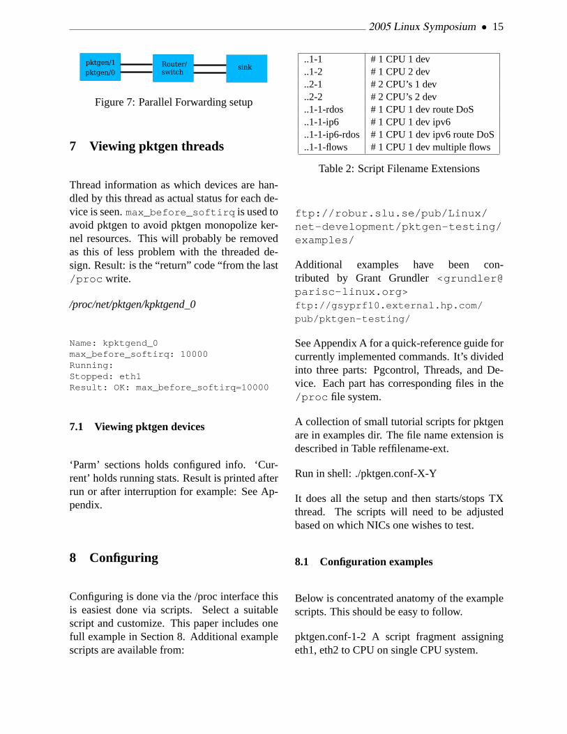
Figure 7: Parallel Forwarding setup
7 Viewing pktgen threads
Thread information as which devices are han-dled by this thread as actual status for each de-vice is seen.max_before_softirq is used toavoid pktgen to avoid pktgen monopolize ker-nel resources. This will probably be removedas this of less problem with the threaded de-sign. Result: is the “return” code “from the last/proc write.
/proc/net/pktgen/kpktgend_0
Name: kpktgend_0max_before_softirq: 10000Running:Stopped: eth1Result: OK: max_before_softirq=10000
7.1 Viewing pktgen devices
‘Parm’ sections holds configured info. ‘Cur-rent’ holds running stats. Result is printed afterrun or after interruption for example: See Ap-pendix.
8 Configuring
Configuring is done via the /proc interface thisis easiest done via scripts. Select a suitablescript and customize. This paper includes onefull example in Section 8. Additional examplescripts are available from:
..1-1 # 1 CPU 1 dev
..1-2 # 1 CPU 2 dev
..2-1 # 2 CPU’s 1 dev
..2-2 # 2 CPU’s 2 dev
..1-1-rdos # 1 CPU 1 dev route DoS
..1-1-ip6 # 1 CPU 1 dev ipv6
..1-1-ip6-rdos # 1 CPU 1 dev ipv6 route DoS
..1-1-flows # 1 CPU 1 dev multiple flows
Table 2: Script Filename Extensions
ftp://robur.slu.se/pub/Linux/net-development/pktgen-testing/examples/
Additional examples have been con-tributed by Grant Grundler<[email protected]>ftp://gsyprf10.external.hp.com/
pub/pktgen-testing/
See Appendix A for a quick-reference guide forcurrently implemented commands. It’s dividedinto three parts: Pgcontrol, Threads, and De-vice. Each part has corresponding files in the/proc file system.
A collection of small tutorial scripts for pktgenare in examples dir. The file name extension isdescribed in Table reffilename-ext.
Run in shell: ./pktgen.conf-X-Y
It does all the setup and then starts/stops TXthread. The scripts will need to be adjustedbased on which NICs one wishes to test.
8.1 Configuration examples
Below is concentrated anatomy of the examplescripts. This should be easy to follow.
pktgen.conf-1-2 A script fragment assigningeth1, eth2 to CPU on single CPU system.

16 • pktgen the linux packet generator
PGDEV=/proc/net/pktgen/kpktgend_0pgset "rem_device_all"pgset "add_device eth1"pgset "add_device eth2"
pktgen.conf-2-2 A script fragment assigningeth1 to CPU0 respectivly eth2 to CPU1.
PGDEV=/proc/net/pktgen/kpktgend_0pgset "rem_device_all"pgset "add_device eth1"
PGDEV=/proc/net/pktgen/kpktgend_1pgset "rem_device_all"pgset "add_device eth2"
pktgen.conf-2-1 A script fragment assigningeth1 and eth2 to CPU0 on a dual CPU system.
PGDEV=/proc/net/pktgen/kpktgend_0pgset "rem_device_all"pgset "add_device eth1"pgset "add_device eth2"
PGDEV=/proc/net/pktgen/kpktgend_1pgset "rem_device_all"
pktgen.conf-1-2 A script fragment assigningeth1, eth2 to CPU on single CPU system.
PGDEV=/proc/net/pktgen/kpktgend_0pgset "rem_device_all"pgset "add_device eth1"pgset "add_device eth2"
pktgen.conf-1-1-rdos A script fragment forroute DoS testing. Note clone_skb 0
PGDEV=/proc/net/pktgen/eth1pgset "clone_skb 0"# Random address with in the# min-max range# pgset "flag IPDST_RND"pgset "dst_min 10.0.0.0"pgset "dst_max 10.255.255.255"
pktgen.conf-1-1-ipv6 Setting device ipv6 ad-dresses.
PGDEV=/proc/net/pktgen/eth1pgset "dst6 fec0::1"pgset "src6 fec0::2"
pktgen.conf-1-1-ipv6-rdos
PGDEV=/proc/net/pktgen/eth1pgset "clone_skb 0"# pgset "flag IPDST_RND"pgset "dst6_min fec0::1"pgset "dst6_max fec0::FFFF:FFFF"
pktgen.conf-1-1-flows A script fragment forroute flow testing. Note clone_skb 0
PGDEV=/proc/net/pktgen/eth1pgset "clone_skb 0"# Random address within the# min-max range# pgset "flag IPDST_RND"pgset "dst_min 10.0.0.0"pgset "dst_max 10.255.255.255"# 8k Concurrent flows at 4 pktspgset "flows 8192"pgset "flowlen 4"
2x4+2 script
#Script contributed by Grant Grundler# <[email protected]># Note! 10 devices
PGDEV=/proc/net/pktgen/kpktgend_0pgset "rem_device_all"pgset "add_device eth3"pgset "add_device eth5"pgset "add_device eth7"pgset "add_device eth9"pgset "add_device eth11"pgset "max_before_softirq 10000"
PGDEV=/proc/net/pktgen/kpktgend_1pgset "rem_device_all"pgset "add_device eth2"

2005 Linux Symposium • 17
pgset "add_device eth4"pgset "add_device eth6"pgset "add_device eth8"pgset "add_device eth10"pgset "max_before_softirq 10000"
# Configure the individual devices
for i in 2 3 4 5 6 7 8 9 10 11do
PGDEV=/proc/net/pktgen/eth$iecho "Configuring $PGDEV"
pgset "clone_skb 500000"pgset "min_pkt_size 60"pgset "max_pkt_size 60"pgset "dst 192.168.3.10$i"pgset "dst_mac 01:02:03:04:05:0$i"pgset "count 0"
doneecho "Running... CTRL-C to stop"PGDEV=/proc/net/pktgen/pgctrlpgset "start"
tail -2 /proc/net/pktgen/eth*
9 Tips for driver/chip testing
When testing a particular driver/chip/platform,start with TX. Use pktgen on the host systemto get a sense of which ptkgen parameters areoptimal and how well a particular NIC can per-form TX. Try with a range of packet sizes from64 bytes to 1500 bytes or jumbo frames.
Then start looking at the RX on the target plat-form by using pktgen to inject packets eitherdirect via crossover cable or via pktgen fromanother host.
Again, vary the packet size etc To isolatedriver/chip from other parts of kernel stack pkt-gen packets can be counted and dropped at var-ious points. See section on detecting pktgenpackets.
Depending on the purpose of the test repeat theprocess with additional devices, one at a time.
Multiple devices are trickier since one needs toknow I/O bus topology. Typically one tries tobalance I/O loads by installing the NICs in the“right” slots or utilizing built-in devices appro-priately.
9.1 Multiple Devices
With multiple devices, it is best to use CTRL-C to stop a test run. This prevents any pktgenthread from stopping before others and skew-ing the test results. Sometimes, one NIC willTX packets faster than another NIC just be-cause of bias in the DMA latency or PCI busarbiter (to name only two of several possibili-ties). Using CTRL-C to stop a test run aborts allpktgen threads at once. This results in a cleansnapshot of how many packets a given configu-ration could generate over the same period oftime. After the CTRL-C is received, pktgenwill print the statistics the same as if the testhad been stopped by a counter going to zero.
9.2 Other testing aspects
To isolate driver/chip from other parts of ker-nel stack, pktgen packets can be counted anddropped at various points. See Section 9.3 ondetecting pktgen packets.
If the tested system only has one interface, thedummy interface can be setup as the output de-vice. The advantage is we can test the systemat very high load and the results are very re-produceable. Of course, other variables suchas different types of offload and checksummingshould be tested as well.
Besides knowing the hardware topology, oneshould know what workloads are expected tobe present on the target system when placed inproduction (i.e. real world use). An FTP servercan see quite a different workload than a web

18 • pktgen the linux packet generator
server, mail handler, or router, etc. Roughly160 Kpps seems to fill a Gigabit link when run-ning an FTP server. While this can vary, it givesan useful estimate of required packet per sec-ond (pps) versus bandwidth for this type of pro-duction system.
For routers the number of routes in the rout-ing table is also an issue as lookup times andother behaviour may be affected. The authorhas taken snapshots from current Internet rout-ing table IPV4 and IPV6 (BGP) and formedinto scripts for this purpose. The routes areadded via the ip utility so the tested system doesnot need any routing connectivity nor routingdaemon. Some scripts are available from:
ftp://robur.slu.se/pub/Linux/net-development/inet_routes/
At last use your fantasy when testing, elaboratewith new setups try to understand how thingsare functioning, monitor interested and relatedvariables add printouts etc. Testing understand-ing and development are closely related.
9.3 Detecting pktgen packets in kernel
Sometimes it’s very useful to monitor/drop pk-tgen packets within the driver/network stack ei-ther at ingress or egress. The technique for bothis essentially the same. The patchlet in Sec-tion 13.1 drops pktgen packets at ingress anduses an unused counter.
Also it should be possible to capture pktgenpackets via the tc command and the u32 clas-sifier which might be a better solution in mostcases.
10 Thanks to. . .
Thanks to Grant Grundler, Jamal Hadi Salim,Jens Låås, and Hans Wassen for comments and
useful insights. This paper covers several yearsof work and conversations with all of the above.
Relevant site:ftp://robur.slu.se://pub/Linux/net-development/pktgen-testing/
Good luck with the linux net-development!

2005 Linux Symposium • 19
11 Appendix A
Table 3: Command Summary
Commands
Pgcontrol commandsstart Starts sending on all threadsstopThreads commandsadd_device Add a device to thread i.e eth0rem_device_all Removes all devices from this threadmax_before_softirq do_softirq() after sending a number of packetsDevice commandsdebugclone_skb Number of identical copies of the same packet 0 means alloc for each skb.
For DoS etc we must alloc new skb’s.clear_counters normally handled automaticallypkt_size Link packet size minus CRC (4)min_pkt_size Range pkt_size setting If < max_pkt_size, then cycle through the port
range.max_pkt_sizefrags Number of fragments for a packetcount Number of packets to send. Use zero for continious sendingdelay Artificial gap inserted between packets in nanosecondsdst IP destination address i.e 10.0.0.1dst_min Same as dst If < dst_max, then cycle through the port range.dst_max Maximum destination IP. i.e 10.0.0..1src_min Minimum (or only) source IP. i.e. 10.0.0.254 If < src_max, then cycle
through the port range.src_max Maximum source IP.dst6 IPV6 destination address i.e fec0::1src6 IPV6 source address i.e fec0::2dstmac MAC destination adress 00:00:00:00:00:00srcmac MAC source adress. If omitted it’s automatically taken from source devicesrc_mac_count Number of MACs we’ll range through. Minimum’ MAC is what you set
with srcmac.dst_mac_count Number of MACs we’ll range through. Minimum’ MAC is what you set
with dstmac.FlagsIPSRC_RND IP Source is random (between min/max),IPDST_RND EtcTXSIZE_RNDUDPSRC_RND

20 • pktgen the linux packet generator
Commands continued
UDPDST_RNDMACSRC_RNDMACDST_RNDudp_src_min UDP source port min, If < udp_src_max, then cycle through the port range.udp_src_max UDP source port max.udp_dst_min UDP destination port min, If < udp_dst_max, then cycle through the port
range.udp_dst_max UDP destination port max.stop Aborts packet injection. Ctrl-C also aborts generator.Note: Use count 0
(forever) and stop the run with Ctrl-C when multiple devices are assignedto one pktgen thread. This avoids some devices finishing before others andskewing the results. We are primarily interested in how many packets alldevices can send at the same time, not absolute number of packets eachNIC sent.
flows Number of concurrent flowsflowlen Length of a flow
12 Appendix B
12.1 Sample pktgen output
/proc/net/pktgen/eth1output after run
Params: count 10000000 min_pkt_size: 60 max_pkt_size: 60frags: 0 delay: 0 clone_skb: 1000000 ifname: eth1flows: 0 flowlen: 0dst_min: 10.10.11.2 dst_max:src_min: src_max:src_mac: 00:00:00:00:00:00 dst_mac: 00:07:E9:13:5C:3Eudp_src_min: 9 udp_src_max: 9 udp_dst_min: 9 udp_dst_max: 9src_mac_count: 0 dst_mac_count: 0Flags:
Current:pkts-sofar: 10000000 errors: 39192started: 1076616572728240us stopped: 1076616585502839us idle: 1037781usseq_num: 11 cur_dst_mac_offset: 0 cur_src_mac_offset: 0cur_saddr: 0x10a0a0a cur_daddr: 0x20b0a0acur_udp_dst: 9 cur_udp_src: 9flows: 0
Result: OK: 12774599(c11736818+d1037781) usec, 10000000 (64byte)782840pps 382Mb/sec (400814080bps) errors: 39192
Results show 10 millon 64 byte packets were sent on eth1 to 10.10.11.2with a rate at 783 kpps

2005 Linux Symposium • 21
\section{Appendix C}\subsection{pktgen.conf-1-1 script}
Below is the full pktgen.conf-1-1 script
\begin{footnotesize}\begin{verbatim}#!/bin/sh
#modprobe pktgen
function pgset() {local result
echo $1 > $PGDEV
result=‘cat $PGDEV | fgrep "Result: OK:"‘if [ "$result" = "" ]; then
cat $PGDEV | fgrep Result:fi
}
function pg() {echo inject > $PGDEVcat $PGDEV
}
# Config Start Here -------------------------------------
# thread config# Each CPU has own thread. Two CPU exammple.# We add eth1, eth2 respectively.
PGDEV=/proc/net/pktgen/kpktgend_0echo "Removing all devices"
pgset "rem_device_all"echo "Adding eth1"
pgset "add_device eth1"echo "Setting max_before_softirq 10000"
pgset "max_before_softirq 10000"
# device config# delay is inter packet gap. 0 means maximum speed.
CLONE_SKB="clone_skb 1000000"# NIC adds 4 bytes CRCPKT_SIZE="pkt_size 60"
# COUNT 0 means forever#COUNT="count 0"COUNT="count 10000000"delay="delay 0"

22 • pktgen the linux packet generator
PGDEV=/proc/net/pktgen/eth1echo "Configuring $PGDEV"
pgset "$COUNT"pgset "$CLONE_SKB"pgset "$PKT_SIZE"pgset "$delay"pgset "dst 10.10.11.2"pgset "dst_mac 00:04:23:08:91:dc"
# Time to runPGDEV=/proc/net/pktgen/pgctrl
echo "Running... ctrl^C to stop"pgset "start"echo "Done"
# Result can be vieved in /proc/net/pktgen/eth1
13 Appendix D
13.1 Patchlet to ip_input.c
Below is the patchlet to count and drop pktgen packets.
--- linux/net/ipv4/ip_input.c.orig Mon Feb 10 19:37:57 2003+++ linux/net/ipv4/ip_input.c Fri Feb 21 21:42:45 2003@@ -372,6 +372,23 @@
IP_INC_STATS_BH(IpInDiscards);goto out;
}
+ {+ __u8 *data = (__u8 *) skb->data+20;++ /* src and dst port 9 --> pktgen */++ if(data[0] == 0 &&+ data[1] == 9 &&+ data[2] == 0 &&+ data[3] == 9) {+ netdev_rx_stat[smp_processor_id()].fastroute_hit++;+ goto drop;+ }+ }+

2005 Linux Symposium • 23
if (!pskb_may_pull(skb, sizeof(struct iphdr)))goto inhdr_error;

24 • pktgen the linux packet generator

TWIN: A Window System for ‘Sub-PDA’ Devices
Keith PackardHP Cambridge Research Laboratory
Abstract
With embedded systems gaining high resolu-tion displays and powerfulCPUs, the desire forsophisticated graphical user interfaces can berealized in even the smallest of systems. Whilethe CPU power available for a given powerbudget has increased dramatically, these tinysystems remain severely memory constrained.This unique environment presents interestingchallenges in graphical system design and im-plementation. To explore this particular space,a new window system,TWIN, has been de-veloped. Using ideas from modern windowsystems in larger environments,TWIN offersoverlapping translucent windows, anti-aliasedgraphics and scalable fonts in a total memorybudget of 100KB.
Motivation
Researchers at the HP Cambridge ResearchLaboratory are building a collection of sub-PDA
sized general purpose networked computers asplatforms for dissociated, distributed comput-ing research. These devices include smallLCD
or OLED screens, a few buttons and occasion-ally some kind of pointing device.
One of the hardware platforms under de-velopment consists of aTMS320 seriesDSP
(200MHz, fixed point, 384KB on-chip RAM),8MB of flash memory, an AgilentADNS-2030Optical mouse sensor, a Zigbee (802.15.4)wireless networking interface and an EpsonL2F50176T00 LCD screen (1.1”, 120 x 160color). At 200MHz, this processor is capable ofsignificant computation, but 384KB holds littledata.
In contrast, early graphical user interfaces fordesktop platforms was more constrained byavailable CPU performance than by memory.Early workstations had at least a million pixelsand a megabyte of physical memory but onlyabout 1MIPS of processing power. Softwarein this environment was much more a matterof what could be made fast enough than whatwould fit in memory.
While the X window system[7] has been portedto reasonably small environments[2], a mini-mal combination of window system server, pro-tocol library and application toolkit consumeson the order of 4 to 5MB of memory, some tentimes more than is available in the target plat-form.
Given the new challenge of providing a graph-ical user interface in these tiny devices, itseemed reasonable to revisit the whole graph-ical architecture and construct a new systemfrom the ground up. TheTWIN window sys-tem (for Tiny WINdow system) is the result ofthis research.

26 • T WIN: A Window System for ‘Sub-PDA’ Devices
Assumptions
The hardware described above can be general-ized to provide a framework within which theTWIN architecture fits. By focusing on specifichardware capabilities and limitations, the win-dow system will more completely utilize thoselimited resources. Of course, over-constrainingthe requirements can limit the potential targetenvironments. Given the very general nature ofexisting window systems, it seems interestingto explore what happens when less variation ispermitted.
The first assumption made was that little-to-no graphics acceleration is available within theframe buffer, and that the frame buffer is at-tached to theCPU through a relatively slowlink. This combination means that most draw-ing should be done with theCPU in local mem-ory, and not directly to the frame buffer. Thishas an additional benefit in encouraging syn-chronized screen updates where intermediaterendering results are never made visible to theuser. If theCPU has sufficient on-chip storage,this design can also reduce power consumptionby reducing off-chip data references.
The second limitation imposed was to require acolor screen with fixed color mapping. Whilethis may appear purely beneficial to the user,the software advantages are numerous as well.Imprecise rendering operations can now gener-ate small nearly invisible errors instead of vis-ibly incorrect results through the use of anti-aliased drawing. With smooth gradations ofcolor available, there is no requirement thatthe system support dithering or other color-approximating schemes.
Finally, TWIN assumes that the target machineprovides respectableCPU performance. Thisreduces the need to cache intermediate render-ing results, like glyph images for text. Hav-ing a homogeneously performant target market
means thatTWIN need support only one gen-eral performance class of drawing operations.For example,TWIN supports only anti-aliaseddrawing; non-antialiased drawing would befaster, but theCPUs supported by twin are re-quired to be fast enough to make this irrelevant.
The combined effect of these environmentallimitations means thatTWIN can provide sig-nificant functionality with little wasted code.Window systems designed for a range of tar-get platforms must often generalize functional-ity and expose applications to variability whichwill not, in practice, ever been experienced bythem. For example, X provides six differentcolor models for monochrome, colormappedand static color displays. In practice, only True-Color (separate monotonic red, green, blue ele-ments in each pixel) will ever be used by themajority of X users. Eliminating choice hasbenefits beyond the mere reduction of windowsystem code, it reflects throughout the applica-tion stack.
Windowing
Windowing can be thought of as the process ofsimulating multiple, separate, two-dimensionalsurfaces sharing the same display. These virtualsurfaces, or ‘windows,’ are then combined intoa single presentation. Traditional window sys-tems do this by presenting a ‘21/2’ dimensionaluser interface which assigns different constantZ values to each object so that the windows ap-pear to be stacked on top of one another.
TWIN provides this traditional metaphorthrough an architecture similar to the Xwindow system Composite extension in thatall applications draw to off-screen imagebuffers which are then combined and placedin the physical frame buffer. This has manyadvantages:

2005 Linux Symposium • 27
• Rendering performance is decoupled fromframe buffer performance. As the embeddedframe buffer controllers include a private framebuffer, the bandwidth available to theCPU forthat memory is quite restricted. Decouplingthese two operations means that rendering canoperate at full main memory speed instead ofthe reduced video controller memory speed• Rendering operations needn’t clip to over-lapping windows. Eliminating the need to per-form clipping reduces the complexity and sizeof the window system by eliminating the codeneeded to construct and maintain the clip listdata structures.• Applications need not deal with damageevents. In a traditional clipping-based windowsystem, applications must be able to reconstructtheir presentation data quickly to provide datafor newly visible portions of windows.• Multiple window image formats can be sup-ported, including those with translucency in-formation. By constructing the physical framebuffer data from the combination of variouswindow contents, it is possible to perform ar-bitrary image manipulation operations on thosewindow contents, including translucency ef-fects.
In the model supported in the X window systemby the Composite extension, an external appli-cation is responsible for directing the systemin constructing the final screen image from theoff-screen window contents. TWIN has a sim-pler model where window contents are com-posited together through a fixed mechanism.This, of course, eliminates significant complex-ity but at the cost of also eliminating significantgenerality. TWIN does not, and is not likely to,support immersive 3D environments.
TWIN tracks rectangular regions of modifiedpixels within each window. When updating thescreen, a single scanline of intermediate stor-age is used to compute new screen contents.The list of displayed windows is traversed and
any section* of the window overlapping thescanline is painted into the intermediate scan-line. When complete, the scanline is sent tothe frame buffer. This single scanline providesthe benefits of a double buffered display with-out the need for a duplicate frame buffer.
Graphics
The availability of small color screens using ei-therLCD or OLED technologies combined withsufficient CPUpower have encouraged the in-clusion of a rendering model designed to takemaximal advantage of the limited pixel reso-lution available. Anti-aliasing and sub-pixeladdressing is used to produce higher fidelityrenderings within the limited screen resolu-tion. Per-pixel translucency is included to ‘seethrough’ objects as well as permit arbitrary ob-ject shapes to minimize unused space on thescreen.
The complete drawing stack provides asimacrulum of thePDF 1.4 drawing environ-ment, complete with affine transforms, colorimage blending and PostScript path construc-tion and drawing tools. Leveraging this classicand well known environment ensures both thatdevelopers will feel comfortable with the toolsand that the system is ‘complete’ in some infor-mal sense.
Pixel Manipulation
TWIN uses the rendering operational modelfrom 81/2[5], the window system developed forthe Plan 9 operating system by Cox and Pike,the same as used in the X render extension[4].This three-operand rendering operator formsthe base upon which all drawing is built:

28 • T WIN: A Window System for ‘Sub-PDA’ Devices
dst = (src IN mask) OVER|SOURCE
dst
The IN, OVER and SOURCE operators are asdefined by Porter and Duff.[6] By manipulat-ing the operands, this single operator performsall of the rendering facilities in theTWIN sys-tem. Geometric operations are performed byconstructing a suitable mask operand based onthe shape of the geometry.
Pixel data are limited inTWIN to three formats,8 bit alpha, 32 bitARGB and 16 bitRGB. Lim-iting formats in this way along with the lim-ited number of operators in the rendering equa-tion provided an opportunity to instantiate eachcombination in custom compositing code. Withthree formats for each operand and two opera-tors, there are 54 different rendering functionsin 13KB of code.
Geometric Objects
For geometric operations,TWIN uses the modelfrom PostScript as implemented in the cairographics system.[8] ‘Paths’ are constructedfrom a sequence of lines and Bézier splines. Anarbitrary path can be convolved with a convexpath to construct a new path representing theoriginal path as stroked by the convex path. Theconvolution operation approximates the outlineof the Minkowski sum of the two paths.
A path can then be drawn by scan convertingit to a mask for use in the rendering operationdescribed above. Because the rendering opera-tion can handle translucency, this scan conver-sion operation does anti-aliasing by samplingthe path in a 4×4 grid over each pixel to com-pute approximate coverage data. This samplinggrid can be easily adjusted to trade quality forperformance.
The application interface includes an affinetransformation from an arbitrary 16.16 fixedpoint coordinate space to 12.4 fixed point pixelspace. The 16.16 fixed point values providereasonable dynamic range for hardware whichdoes not include floating point acceleration.The 12.4 fixed point pixel coordinates providesufficient resolution to accurately reproduceobject geometry on the screen. Note that thescreen is therefore implicitly limited to 4096pixels square.
Glyph Representation
Providing text at multiple sizes allows the userinterface to take maximal advantage of the lim-ited screen size. This can either be done bystoring pre-computed glyphs at multiple sizesor preparing glyphs at run-time from scalabledata. Commercial scalable font formats all rep-resent glyphs in outline form. The resultingglyph is constructed by filling a complex shapeconstructed from lines and splines. The out-line data for one face for theASCII characterset could be compressed to less than 7KB – sig-nificantly smaller than the storage needed for abitmap face at a single size.
However, a straightforward rasterization of anoutline does not provide an ideal presentationon the screen. Outline fonts often include hint-ing information to adjust glyph shapes at smallpixel sizes to improve sharpness and readabil-ity. This hinting information requires signif-icantly more code and data than the outlinesthemselves, making it impractical for the targetdevice class.
An alternative representation for glyphs is asstroke data. With only the path of the penrecorded, the amount of data necessary to rep-resent each glyph is reduced. More signifi-cantly, with the stroke width information iso-

2005 Linux Symposium • 29
lated from the stroke path, it is possible to auto-matically adjust the stroke positions to improvethe presentation on the screen. A secondary ad-justment of the pen shape completes the hintingprocess. The results compare favorably withfully hinted outline text.
An additional feature of the stroke representa-tion is that producing oblique and bold variantsof the face are straightforward; slanting the textwithout changing the pen shape provides a con-vincing oblique while increasing the pen widthproduces a usable bold.
The glyphs themselves have a venerable his-tory. The shapes come from work done byDr A.V. Hershey for the US National Bureauof Standards. Those glyphs were designed forperiod pen plotters and were constructed fromstraight line segments on a relatively low reso-lution grid. The complete set of glyphs containsmany different letterforms from simple gothicshapes to letters constructed from multiple par-allel strokes that provide an illusion of vary-ing stroke widths. Many additional decorativeglyphs were also designed.
From this set of shapes, a simple gothic set ofletters, numbers and punctuation was chosen.Additional glyphs were designed to provide acompleteASCII set. The curves within the Her-shey glyphs, designed as sequences of shortline segments, were replaced by cubic splines.This served both to improve the appearance ofthe glyphs under a variety of transforms as wellas to reduce the storage required for the glyphsas a single cubic spline can replace many linesegments. Figure 1 shows a glyph as originallydesigned with 33 line segments and the sameglyph described as seven Bézier splines. Stor-age for this glyph was reduced from 99 to 52bytes.
Figure 1: Converting Lines To Splines
Glyph Hinting
Given the desire to present text at a varietyof sizes, the glyph shapes need to undergo ascaling transformation and then be rasterizedto create an image. Unless this scaling is re-stricted to integer values, the edges of the re-sulting strokes will not necessarily align withthe pixel grid. The resulting glyphs will appearfuzzy and will be hard to read.
To improve the appearance of the glyphs on thescreen, a straightforward mechanism was de-veloped to reposition the glyph control pointsto improve the rasterized result. The glyph datawas augmented to include a list of X and a listof Y coordinates. Each ‘snap’ list contains val-ues along the respective axis where some pointwithin the glyph is designed to lie on a pixelboundary. These were constructed automati-cally by identifying all vertical and horizon-tal segments of each glyph, including splineswhose ends are tangent to the vertical or hori-zontal.
The glyph coordinates are then scaled to the de-sired size. The two snap lists (X and Y) areused to push glyph coordinates to the nearestpixel grid line. Coordinates between points ona snap list are moved so that the relative dis-tance from the nearest snapped coordinates re-main the same. The pen width is snapped to thenearest integer size. If the snapped pen widthis odd, the entire glyph is pushed1/2 a pixel

30 • T WIN: A Window System for ‘Sub-PDA’ Devices
in both directions to align the pen edges withthe pixel edges. Figure 2 shows a glyph beinghinted in this fashion.
Figure 2: Hinting A Glyph
The effect is to stretch or shrink the glyph toalign vertical and horizontal strokes to the pixelgrid. Glyphs designed with evenly spaced ver-tical or horizontal stems (like ‘m’) may end upunevenly spaced; a more sophisticated hintingsystems could take this into account by preserv-ing the relative spacing among multiple strokes.
User Interface Objects
With the window system supporting a singlescreen containing many windows, the toolkitextends this model by creating a single top-level widget. This top-level widget contains asingle box for layout purposes. Each box cancontain a number of widgets or other boxes.
Layout within each box is done either hori-zontally or vertically with an algorithm whichcomes from the Layout Widget[3] that the au-thor developed for Xt[1] library. Each wid-get has a natural size and stretch in both di-rections. The natural size and stretch of a boxis computed from the objects it contains. This
forms the sole geometry management mecha-nism within the toolkit and is reasonably com-petent at both constructing a usable initial lay-out and adapting to externally imposed sizechanges.
Process & Thread Model
TWIN was initially developed to run on a cus-tom embedded operating system. This operat-ing system design initially included simple co-operative threading support, andTWIN was de-signed to run different parts of the window sys-tem in different threads:• Input would run in one thread, events weredispatched without queuing directly to the re-ceiving object.• Each window would have a thread to redis-play the window contents. These threads wouldblock on a semaphore awaiting a change in ap-plication state before reconstructing the win-dow contents. Per window locks could blockupdates until the application state was consis-tent.• The window system had a separate threadto compose the separate window contents intothe final screen display. The global redis-play thread would block on a semaphore whichthe per-window redisplay threads would signalwhen any window content changed. A globalsystem lock could block updates while any ap-plication state was inconsistent.
This architecture was difficult to manage asit required per-task locking between input andoutput. The lack of actual multi-tasking of theapplication processing eliminated much of thevalue of threads.
Once this was working, support for threadingwas removed from the custom operating sys-tem.

2005 Linux Symposium • 31
With no thread support at all,TWIN was re-designed with a global event loop monitoringinput, timers and work queues. The combi-nation of these three mechanisms replaced thecollection of threads described above fairly eas-ily, and the complexities of locking between in-put and output within a single logical task wereremoved.
Of course, once this was all working, thecustom operating system was replaced withucLinux.
While the single thread model works fine inucLinux, it would be nice to split separate outtasks into processes. Right now, all of the tasksare linked into a monolithic executable. Thismodularization work is underway.
Input Model
A window system is responsible for collectingraw input data from the user in the form of but-ton, pointer and key manipulation and distribut-ing them to the appropriate applications.
TWIN takes a simplistic approach to this pro-cess, providing a single immutable model.Pointer events are delivered to the window con-taining the pointing device. Transparent areasof each window are excluded from this contain-ment, so arbitrary shapes can be used to selectfor input.
TWIN assumes that any pointing device willhave at least one associated signal – a mousebutton, a screen touch or perhaps somethingelse. When pressed, the pointing device is‘grabbed’ by the window containing the pointerat that point. Motion information is deliveredonly to that window until the button is released.
Device events not associated with a pointer,such as keyboards, are routed to a fixed ‘active’
window. The active window is set under ap-plication control, such as when a mouse buttonpress occurs within an inactive window. Theactive window need need not be the top-mostwindow.
Under both the original multi-threaded modeland the current single-threaded model, there isno event queueing within the window system;events are dispatched directly upon being re-ceived from a device. This is certainly easy tomanage and allows motion events to be easilydiscarded when the system is too busy to pro-cess them. However, with the switch to multi-ple independent processes running on ucLinux,it may become necessary to queue events be-tween the input collection agent and the appli-cation processing them.
Within the toolkit, events are dispatchedthrough each level of the hierarchy. Withineach box, keyboard events are statically routedto the active box or widget while mouse eventsare routed to the containing box or widget. Byexplicitly dispatching down each level, the con-taining widgets and boxes can enforce whateverpolicy they like for event delivery, includingmouse or keyboard grabs, focus traversal andevent replay.
While this mechanism is fully implemented,much investigation remains to be done to ex-plore what kinds of operations are useful andwhether portions of what is now application-defined behavior should be migrated into com-mon code.
Window Management
TWIN embeds window management right intothe toolkit. Support for resize, move and min-imization is not under the control of an exter-nal application. Instead, the toolkit automat-ically constructs suitable decorations for each

32 • T WIN: A Window System for ‘Sub-PDA’ Devices
window as regular toolkit objects and the nor-mal event dispatch mechanism directs windowmanagement activities.
While external management is a valuable archi-tectural feature in a heterogeneous desktop en-vironment, the additional space, time and com-plexity rules this out in today’s Sub-PDA world.
Status and Future Work
As computing systems continue to press intoever smaller environments, the ability to bringsophisticated user interface technologies alonggreatly increases both the value of such prod-ucts as well as the scope of the potential mar-ket.
The TWIN window compositing mechanism,graphics model and event delivery system havebeen implemented using a mock-up of the hard-ware running on Linux using the X windowsystem. Figure 3 shows most of the current ca-pabilities in the system.
While the structure of theTWIN window sys-tem is complete, the toolkit is far from com-plete, having only a few rudimentary widgets.And, as mentioned above, the port to ucLinux isnot yet taking advantage of the multiple processsupport in that environment. These changeswill likely be accompanied by others asTWIN
is finally running on the target hardware.
In the x86 emulation environment, the windowsystem along with a small cadre of demonstra-tion applications now fits in about 50KB of textspace with memory above that limited largelyto the storage of the off-screen window con-tents. Performance on a 1.2GHz laptop proces-sor is more than adequate; it will be rather inter-esting to see how these algorithms scale downto the targetCPU.
The current source code is available from viaCVS, follow the link from http://keithp.com.The code is licensed with anMIT -style license,permitting liberal commercial use.
References
[1] Paul J. Asente and Ralph R. Swick.XWindow System Toolkit. Digital Press,1990.
[2] William R. Hamburgen, Deborah A.Wallach, Marc A. Viredaz, Lawrence S.Brakmo, Carl A. Waldspurger, Joel F.Bartlett, Timothy Mann, and Keith I.Farkas. Itsy: Stretching the Bounds ofMobile Computing.IEEE Computer,34(4):28–35, April 2001.
[3] Keith Packard. The LayoutWidget: A TeXStyle Constraint Widget Class.The XResource, 5, Winter 1993.
[4] Keith Packard. Design andImplementation of the X RenderingExtension. InFREENIX Track, 2001Usenix Annual Technical Conference,Boston, MA, June 2001. USENIX.
[5] Rob Pike.draw - screen graphics. BellLaboratories, 2000. Plan 9 Manual PageEntry.
[6] Thomas Porter and Tom Duff.Compositing Digital Images.ComputerGraphics, 18(3):253–259, July 1984.
[7] Robert W. Scheifler and James Gettys.XWindow System. Digital Press, thirdedition, 1992.
[8] Carl Worth and Keith Packard. Xr:Cross-device Rendering for VectorGraphics. InProceedings of the OttawaLinux Symposium, Ottawa, ON, July 2003.OLS.

2005 Linux Symposium • 33
Figure 3: Sample Screen Image

34 • T WIN: A Window System for ‘Sub-PDA’ Devices

RapidIO for Linux
Matt PorterMontaVista Software, Inc.
Abstract
RapidIO is a switched fabric interconnect stan-dard intended for embedded systems. Provid-ing a message based interface, it is currentlycapable of speeds up to 10Gb/s full duplexand is available in many form factors includ-ing ATCA for telecom applications. In this pa-per, the author introduces a RapidIO subsystemfor the Linux kernel. The implementation pro-vides support for discovery and enumeration ofdevices, management of resources, and a con-sistent access mechanism for drivers and otherkernel facilities. As an example of the use ofthe subsystem feature set, the author presentsa Linux network driver implementation whichcommunicates via RapidIO message packets.
1 Introduction to RapidIO
1.1 Busses and Switched Fabrics
To date, most well known system interconnecttechnologies have been shared memory bus de-signs. ISA, PCI, and VMEbus are all examplesof shared memory bus systems. A shared mem-ory bus interconnect will have a specific buswidth which is measured by the number of datalines routed to each participant on the bus. An
arbitration mechanism is required to determinewhich participant owns the bus for purposes ofasserting an address-data cycle onto the bus.Other participants will decode the address-datacycle and latch data locally if the address cycleis intended for them. In the shared memory busarchitecture, there is one global address spaceshared amongst all participants.
Switched fabric interconnect technology hasbeen around for some time with proprietary im-plementations like StarFabric. In recent yearsthough, standardized switched fabrics like Hy-perTransport, Infiniband, PCI Express, and Ra-pidIO have become more familiar names. Aswitched fabric interconnect is usually mod-eled much like a switched network architecture.However, it provides features that a chip tochip or intra-chassis conventional shared mem-ory bus standard would provide. Each nodehas at least one link that can be connectedpoint to point or into a switch element. Animplementation-specific routing method deter-mines packet routing in the network. Typi-cally, a switched fabric interconnect incorpo-rates some method of sending messages andevents through the network. In some cases,the switched fabric will implement memorymapped I/O over the network.
• 35 •

36 • RapidIO for Linux
Logical Layer
MMIO Messaging
Transport Layer
8-bit Device ID 16-bit Device ID
Physical Layer
Parallel Serial8-bit/16-bit x1/x4
Figure 1: RapidIO Layers
1.2 RapidIO Overview
The RapidIO interconnect technology wasoriginally created by Motorola for use in em-bedded computing systems. Motorola (nowFreescale Semiconductor) later created the Ra-pidIO Trade Association (RTA) to guide futuredevelopment of the specification. A number ofembedded silicon vendors are active membersof the RTA and are now shipping or announc-ing RapidIO devices.
The RapidIO specification is divided into threedistinct layers. These layers are illustrated inFigure 1.
1. Logical LayerProvides methods for memory mapped I/O(MMIO) and message-based access to de-vices. MMIO allows for accesses within alocal memory space to generate read/writetransactions within the address space of aremote device. Each device has a uniqueRapidIO address space that can range from34-bits to 66-bits in size. RapidIO pro-vides a messaging model with mailboxand doorbell facilities. A mailbox is a
hardware port which can send and receivemessages up to 4KB in size. A doorbellis a specialized message port which can beused for event notifications similar to mes-sage signaled interrupts.
2. Transport LayerImplements the device ID routing method-ology. In RapidIO, packets are routed bya unique device ID. Two different sizes ofdevice IDs are defined , either a small (8-bit) or large (16-bit) device ID. The smalldevice ID allows a maximum of 256 de-vices whereas the large device ID allows amaximum of 65536 devices.
3. Physical LayerOffers either parallel or serial implemen-tations for the physical interconnect. Theparallel version is available in 8-bit or 16-bit configurations with full duplex speedsup to 8 Gb/s and 16 Gb/s, respectively.The serial implementation offers lane con-figurations of x1 or x4. In the x1 config-uration, the single lane offers up to 3.125Gb/s full duplex data throughput. In thex4 configuration, each lane offers up to2.5Gb/s full duplex data throughput result-ing in 10 Gb/s total bandwidth.
1.3 RapidIO versus PCI Express
RapidIO is often compared to PCI Express be-cause of the popularity of PCI Express in thecommodity PC workstation/server market. Onthe surface, both seem very similar, offeringfeatures that improve upon the use of conven-tional PCI as a system interconnect. RapidIO,however, is designed with some features tar-geted at specific embedded system needs thatwill likely facilitate its inclusion in many appli-cations. There are now embedded processorsavailable which include both PCI Express andRapidIO support on the chip.
2005 Linux Symposium • 37
PCI Express and RapidIO have similar data ratecapabilities. PCI Express offers lane configura-tions of x1 through x32 where each lane offers2 Gb/s full duplex data throughput. In a typicalPC implementation there is a single x16 slot forgraphics that handles 32 Gb/s full duplex andmultiple x1 slots which can handle 4 Gb/s fullduplex.
Both interconnects also have similar discoverymodels. A separate set of transactions is usedto access configuration space registers. Con-figuration space accesses are used to determineexistence of nodes in the system and additionalinformation about those nodes.
A major difference between PCI Express andRapidIO is in system topology capability. PCIExpress is backward compatible with PCI andtherefore depends on the host and multipleslave device model. RapidIO is designed formultiple hosts in the system performing redun-dant discovery. In addition, it can be configuredin any network topology allowing direct nodeto node communication.
Device addressing is very different as well. InPCI Express, the globally shared address spacewith hierarchical windows of address space isretained from PCI. This is important for back-ward compatibility of software and allows rout-ing of packets via base address assignments.RapidIO’s device ID based routing simplifieschanges to the network due to device failure orhot plug events.
PCI Express does not offer a standardized mes-saging facility. Most modern distributed appli-cations are based on message passing architec-tures.
2 RapidIO Hardware
The current generation RapidIO parts use an 8-bit wide parallel physical layer. These parts can
support up to 8Gb/s full duplex data through-put. The first RapidIO processor elements(endpoints with a processor) are Freescale’sMPC8540 and MPC8560 Systems-on-a-Chip(SoC). The first RapidIO switch is the TundraTsi500.
The first commercially available system withthese parts is the STx GP3 HIPPS2 de-velopment platform. This system includesone or more STx GP3 boards containing theMPC8560 processor and a HIPPS2 RapidIObackplane with two Tsi500 switches. TheLinux RapidIO subsystem is being developedusing this platform with two STx GP3 boardsplugged into the HIPPS2 backplane.
3 Linux RapidIO Subsystem
3.1 Subsystem Overview
Due to the discovery mechanism similaritiesbetween PCI and RapidIO, the RapidIO sub-system has a structure which is similar to thatof the PCI subsystem. The subsystem hooksinto the standard Linux Device Model (LDM)in a similar fashion to other busses in the ker-nel. RapidIO specific device and bus typesare defined and registered with the LDM. Thecore subsystem is designed such that there isa clear separation between the generic subsys-tem interfaces and architecture specific inter-faces which support RapidIO. Finally, a set ofsubsystem device driver interfaces is defined toabstract access to facilities by device drivers.
3.2 Subsystem Core
The core of the Linux RapidIO subsystem re-volves around four major components.

38 • RapidIO for Linux
1. Master Port. A master port is an inter-face which allows RapidIO transactions tobe transmitted and received in a system.A master port provides a bridge from aprocessor running Linux into the switchedfabric network.
2. Device. A RapidIO device is any endpointor switch on the network.
3. Switch. A RapidIO switch is a specialclass of device which routes packets be-tween point to point connections to reachtheir final destination.
4. Network. A RapidIO network comprises aset of endpoints and switches that are in-terconnected.
Each of these components is mapped into a sub-system structure. The RapidIO subsystem usesthese structures as the root handle for manipu-lating the hardware components abstracted bythe structures.
struct rio_mport (Figure 2) contains in-formation regarding a specific master port.Master port specific resources such as inboundmailboxes and doorbells are contained in thisstructure. If a master port is defined as a enu-merating host, then the structure will containa unique host device ID. The host device IDis used for multi-host locking purposes duringenumeration.
struct rio_switch (Figure 3) containsinformation about a RapidIO switch device.The structure is populated during enumerationand discovery of the system with informationsuch as the number of hops to the switch andthe routing table present in the switch. In ad-dition, pointers to switch specific routing tableoperations reside here.
struct rio_dev (Figure 4) contains infor-mation about an endpoint or switch that is part
of the RapidIO system. Fields are present tocache many common configuration space reg-isters.
struct rio_net (Figure 5) contains in-formation about a specific RapidIO networkknown to the system. It defines a list of alldevices that are part of the network. Anotherlist tracks all of the local processor master portsthat can access this network. Thehport fieldpoints to the default master port which is usedto communicate with devices within the net-work.
3.3 Subsystem Initialization
In order to initialize the RapidIO subsystem, anarchitecture must register at least one masterport to send and receive transactions within theRapidIO network. Asubsys_initcall()is registered which is responsible for any arch-specific RapidIO initialization. This includeshardware initialization and registration of ac-tive master ports in the system. The finalstep of the initcall is to executerio_init_mports() which performs enumeration anddiscovery on all registered master ports.
3.4 Enumeration and Discovery
The enumeration and discovery process is im-plemented to comply with the multiple hostenumeration algorithm detailed in theRapidIOInterconnect Specification: Annex I[1]. Enu-meration is performed by a master port whichis designated as a host port. A host port is de-fined as a master port which has a host deviceID greater than or equal to zero. A host deviceID is assigned to a master port in a platformspecific manner or can be passed on the com-mand line.

2005 Linux Symposium • 39
struct rio_mport {struct list_head dbells; / ∗ list of doorbell events ∗ /
struct list_head node; / ∗ node in global list of ports ∗ /
struct list_head nnode; / ∗ node in net list of ports ∗ /
struct resource iores;
struct resource riores[RIO_MAX_MPORT_RESOURCES];
struct rio_msg inb_msg[RIO_MAX_MBOX];
struct rio_msg outb_msg[RIO_MAX_MBOX];
int host_deviceid; / ∗ Host device ID ∗ /
struct rio_ops ∗ops; / ∗ maintenance transaction functions ∗ /
unsigned char id; / ∗ port ID, unique among all ports ∗ /
unsigned char index; / ∗ port index, unique among all portinterfaces of the same type ∗ /
unsigned char name[40];
};
Figure 2: struct rio_mport
struct rio_switch {struct list_head node;
u16 switchid;
u16 hopcount;
u16 destid;
u16 route_table[RIO_MAX_ROUTE_ENTRIES];
int ( ∗add_entry)(struct rio_mport ∗mport, u16 destid, u8 hopcount,
u16 table, u16 route_destid, u8 route_port);
int ( ∗get_entry)(struct rio_mport ∗mport, u16 destid, u8 hopcount,
u16 table, u16 route_destid, u8 ∗route_port);
};
Figure 3: struct rio_switch

40 • RapidIO for Linux
struct rio_dev {struct list_head global_list; / ∗ node in list of all RIO devices ∗ /
struct list_head net_list; / ∗ node in per net list ∗ /
struct rio_net ∗net; / ∗ RIO net this device resides in ∗ /
u16 did;
u16 vid;
u32 device_rev;
u16 asm_did;
u16 asm_vid;
u16 asm_rev;
u16 efptr;
u32 pef;
u32 swpinfo; / ∗ Only used for switches ∗ /
u32 src_ops;
u32 dst_ops;
struct rio_switch ∗rswitch; / ∗ RIO switch info ∗ /
struct rio_driver ∗driver; / ∗ RIO driver claiming this device ∗ /
struct device dev; / ∗ LDM device structure ∗ /
struct resource riores[RIO_MAX_DEV_RESOURCES];
u16 destid;
};
Figure 4: struct rio_dev
struct rio_net {struct list_head node; / ∗ node in list of networks ∗ /
struct list_head devices; / ∗ list of devices in this net ∗ /
struct list_head mports; / ∗ list of ports accessing net ∗ /
struct rio_mport ∗hport; / ∗ primary port for accessing net ∗ /
unsigned char id; / ∗ RIO network ID ∗ /
};
Figure 5: struct rio_net

2005 Linux Symposium • 41
During enumeration, maintenance transactionsare used to access the configuration space of de-vices. A maintenance transaction has two com-ponents to address a device, a device ID anda hopcount. The device ID is normally usedfor endpoint devices to determine if they shouldaccept a packet. It is a requirement for all de-vices to ignore the device ID and accept anytransaction during enumeration. Switches are adifferent case, however, as they do not imple-ment a device ID. Transactions which reach aswitch device must have their hopcount set ap-propriately. If a maintenance transaction with ahopcount of 0 reaches a switch, then the switchwill process the packet against its own configu-ration space. If a maintenance transaction has ahopcount greater than 0, then the switch decre-ments the hopcount in the packet and forwardsit along according to the route set for the corre-sponding device ID in the packet.
The enumeration process walks the networkdepth first. Like PCI enumeration, this is eas-ily implemented by recursion. When a deviceis found, the Host Device ID Lock Register iswritten to ensure that the enumerator has exclu-sive enumeration ownership of the device. Thedevice’s capabilities are then queried to deter-mine if it is a switch or endpoint device.
If the device is an endpoint, it is allocated a newunique device ID and this value is written tothe endpoint. A newrio_dev is allocated andinitialized.
If the device is a switch, its vendor and de-vice ID are queried against a table of knownRapidIO switches. A switch table entry has aset of switch routing operations which are spe-cific to the located switch. The routing opera-tions are used to read and write route entries inthe switch. Newrio_dev andrio_switchstructures are then allocated and initialized.
Enumeration past a switch device is accom-plished by iterating over each active switch port
on the switch. For each active link, a route toa fake device ID (0xFF for 8-bit systems and0xFFFF for 16-bit systems) is written to theroute table. The algorithm recurses by callingitself with hopcount + 1 and the fake device IDin order to access the device on the active port.While traversing the network, the current allo-cated device ID is tracked. When the depth firsttraversal completes, the recursion unwinds andpermanent routes are written into the switchrouting tables. The device IDs that were foundbeyond a switch port are assigned route entriespointing to the port which they were found be-hind.
When the host has completed enumerationof the entire network it callsrio_clear_locks() to clean up. For each device in thesystem, it writes a magic "enumeration com-plete" value to the Component Tag Register.This register is essentially a scratch pad registerreserved for enumeration housekeeping. Afterthis process, all Host Device ID Lock Registersare cleared. Remote nodes that are to initiatepassive discovery of the network wait for themagic value to appear in the Component TagRegister and then begin discovery.
The discovery process is similar to the enumer-ation process that has already been described.However, the discovery process is performedpassively. This means that all devices in thenetwork are traversed without modifying de-vice IDs or routing tables. This is necessaryin the case where there are multiple enumer-ation capable endpoints in the system. Typ-ically, only one or two processors with end-points will be designated as enumerating hosts.Out of the competing enumeration hosts, onlyone host can win. The losing hosts and othernon-enumerating processors are forced to waituntil enumeration is complete. At that point,they may traverse the network to find all de-vices without disturbing the network configu-ration. When discovery completes, the Linux

42 • RapidIO for Linux
Switch
0
3
2
1ProcessorElement
3
ProcessorElement
2
ProcessorElement
1
ProcessorElement
0
(Host)
Figure 6: Example RapidIO System
RapidIO subsystem will have a complete viewof all RapidIO devices in the network.
In the passive discovery process, the network iswalked depth first as with enumeration. How-ever, the existing route table entries are uti-lized to generate transactions that pass througha switch. When an endpoint device is discov-ered, ario_dev is allocated but the deviceID is retrieved from the value written in theBase Device ID Register. When a switch de-vice is found, discovery iterates over each ac-tive switch port as with enumeration. How-ever, in order to generate transactions for de-vices beyond that switch port, the routing ta-ble is scanned for an entry which is routed outthat switch port. Using the device ID associ-ated with the switch port, discovery issues atransaction with the associated device ID anda hopcount equal to the number of hops intothe network. The process continues in a similarmanner as described with enumeration until alldevices have been discovered.
3.5 Enumeration and Discovery Example
Figure 6 illustrates a typical RapidIO system.There are four processor elements (PEs) num-bered zero through three. Each PE provides Ra-pidIO endpoint functionality and is connectedto each of four ports on the switch in the center.PE 0 is the only designated enumerating host inthe system and is assigned a host device ID of 0.PEs 1-3 do not perform enumeration, but ratherwait for the signal indicating that enumerationhas been completed by PE 0.
PE 0 begins enumeration by attempting to ob-tain the host device ID lock on the adjoiningdevice. The transaction to configuration spaceis issued with a hopcount of 0 and a device IDof 0xFF. Since the hopcount of the transactionis 0, the switch will process the request and al-low PE 0 to obtain the lock. Once the lockis obtained, PE 0 queries the device to learnthat it is a switch and allocatesrio_dev andrio_switch structures.
PE 0 queries the switch to determine that thereare 4 ports with active links present. PE 0 thenbegins a loop to iterate over the 4 active ports,skipping the input port which it is using to ac-cess the switch device. For each active switchport, PE 0 performs the following:
1. Writes a route entry that assigns device ID0xFF to the current active switch port.
2. Issues configuration space transactionswith a hopcount of 1 to access the devicesthat are one hop from PE 0:
• Obtains the host device ID lock foreach device.
• Queries the device to determine thatit is an endpoint and allocates ario_dev structure.

2005 Linux Symposium • 43
• Assigns the next available device IDto the endpoint. PEs 1-3 are assigneddevice IDs 0x01-0x03, respectively.
3. Assigns route entries corresponding to theswitch ports where the PEs were discov-ered. Route entries for device IDs 0x01-0x03 are assigned to switch ports 1-3, re-spectively.
After this process completes, PE 0 writes themagic "enumeration complete" value into theComponent Tag Register on each device. Thisis followed by PE 0 releasing the host device IDlock on each device in the system. Once PEs 1-3 detect that enumeration is complete, they arefree to begin their discovery process.
3.6 Driver Interface
RapidIO device drivers are provided a specificset of functions to use in their implementation.In order to guarantee proper functioning of thesubsystem, drivers may not access hardware re-sources directly.
Configuration space access is managed similarto configuration space access in the PCI sub-system.
• rio_config_read_8()rio_config_read_16()rio_config_read_32()rio_config_write_8()rio_config_write_16()rio_config_write_32()
Read or write a specific size at an offset ofa device.
• rio_local_config_read_8()rio_local_config_read_16()rio_local_config_read_32()rio_local_config_write_8()
rio_local_config_write_16()rio_local_config_write_32()
Read or write a specific size at an off-set of the local master port’s configurationspace.
Several calls handle the ownership and initial-ization of mailbox and doorbell resources on amaster port or remote device.
• rio_request_outb_mbox()rio_request_inb_mbox()
Claim ownership of an outbound or in-bound mailbox, initialize the mailbox forprocessing of messages, and register a no-tification callback. The outbound mailboxcallback provides a interrupt context eventwhen a message has been sent. The in-bound mailbox callback provides an eventwhen a message has been received.
• rio_release_outb_mbox()rio_release_inb_mbox()
Give up ownership of an outbound or in-bound mailbox and unregister notificationcallback.
• rio_request_outb_dbell()
Claim ownership of a range of doorbellson a remote device. Ownership is onlyvalid for the local processor.
• rio_request_inb_dbell()
Claim ownership of a range of doorbellson the inbound doorbell queue, initializethe doorbell queue, and register a call-back. The doorbell callback provides anevent when a doorbell within the regis-tered range is received.
• rio_release_outb_dbell()
Give up ownership of a range of doorbellson a remote device.

44 • RapidIO for Linux
• rio_release_inb_dbell()
Give up ownership of a range of doorbellson the inbound doorbell queue.
Several calls provide access to doorbell andmessage queues.
• rio_send_doorbell()
Send a doorbell message to a specific de-vice.
• rio_add_outb_message()
Add a message to an outbound mailboxqueue.
• rio_add_inb_buffer()
Add an empty buffer to an inbound mail-box queue.
• rio_get_inb_message()
Get the next available message from an in-bound mailbox queue.
3.7 Architecture Interface
Every architecture must provide implementa-tions for a set of RapidIO functions. Thesefunctions manage hardware-specific featuresof configuration space access, mailbox access,and doorbell access.
• rio_ops.lcwrite()rio_ops.lcread()rio_ops.cwrite()rio_ops.cread()
Hardware specific implementations forgeneration of read and write transac-tions to configuration space. These mas-ter port specific routines are assigned toa struct rio_ops which is in turnbound to astruct rio_mport . These
low-level operations are used by the driverinterface configuration space access rou-tines.
• rio_ops.dsend()
Hardware specific implementation forgeneration of a doorbell write transaction.This master port specific routine is as-signed to astruct rio_mport andused by therio_send_doorbell()call.
• rio_hw_open_outb_mbox()rio_hw_open_inb_mbox()
Hardware specific initialization for out-bound and inbound mailbox queues.
• rio_hw_close_outb_mbox()rio_hw_close_inb_mbox()
Hardware specific cleanup for outboundand inbound mailbox queues.
• rio_hw_add_outb_message()
Hardware specific implementation to adda message buffer to the outbound mailboxqueue.
• rio_hw_add_inb_buffer()
Hardware specific implementation to addan empty buffer to the inbound mailboxqueue.
• rio_hw_get_inb_message()
Hardware specific implementation to getthe next available inbound message.
An architecture must also implement inter-rupt handlers for mailbox and doorbell queueevents. Typically, inbound doorbell and mail-box hardware will generate a hardware inter-rupt to indicate that a message has arrived. Out-bound doorbell hardware will typically gener-ate a hardware interrupt when a message has

2005 Linux Symposium • 45
been successfully sent. The architecture inter-rupt handler must process the event in an ap-propriate manner for the message type and ac-knowledge the hardware interrupt.
For inbound doorbell messages, the handlermust extract the doorbell message info andcheck for a callback that has been regis-tered for the doorbell message it has re-ceived. If a callback has been registered (usingrio_request_inb_dbell() ) for a door-bell range that includes the received doorbellmessage, the callback is executed. The call-back indicates the source, destination, and 16-bit info field (the doorbell message) that wasreceived.
A mailbox interrupt handler must execute theregistered callback for the mailbox that gen-erated the hardware interrupt. It may be re-quired to do some hardware-specific ring buffermanagement and must acknowledge the hard-ware interrupt. The callback is registered us-ing rio_request_inb_mbox() or rio_request_outb_mbox()
3.8 Device Model
The RapidIO subsystem ties into the Linux De-vice Model in a similar way to most other de-vice subsystems. A RapidIO bus is registeredwith the device subsystem and each RapidIOdevice is registered as a child of that bus. Ra-pidIO specificmatch anddev_attrs imple-mentations are provided.
rio_match_bus() implementation is asimple device to driver matching implementa-tion. It compares vendor and device IDs ofa candidate RapidIO device to determine if adriver will claim ownership of the device.
Therio_dev_attrs[] implementation ex-ports all of the common register fields in the
rio_dev structure to sysfs. In addition to thestandarddev_attrs sysfs support, aconfignode is exported similar to the same node in thePCI subsystem. It provides userspace access tothe 2MB configuration space on each RapidIOdevice.
RapidIO specific implementations ofprobe() , remove() , and driver register/unregister are also provided.
4 RapidIO Messaging NetworkDriver ( rionet)
4.1 rionet Overview
With the subsystem in place, a driver is stillneeded to make use of the new functional-ity. Since the first RapidIO parts availableare processors with RapidIO interfaces, a net-work driver to provide communication over theRapidIO switched fabric makes good sense.The RapidIO messaging model makes thiseasy since managing outbound and inboundmessages is much like a managing a moderndescriptor-based network controller.
4.2 rionet Features
rionethas the following features:
• Ethernet driver model for simplicity
• Dynamic discovery of network peers usingdoorbell messages
• Unique MAC address generation based onRapidIO device ID
• Maximum MTU of 4082
• Uses standard RapidIO subsystem mes-sage model to work on any RapidIO end-points with mailboxes and doorbells

46 • RapidIO for Linux
4.3 rionet Implementation
The rionet driver is initialized with ario_register_driver() call. The id_table is configured to match all RapidIO de-vices so that therionet_probe() call willqualify rionet devices. The probe routine ver-ifies that the device has mailbox and doorbellcapabilities. If the device is mailbox and door-bell capable, then it is added to a list of poten-tial rionetpeers. If at least one potential peer isfound, the local RapidIO device is queried forits device ID. The MAC address is generated byconcatenating 3 bytes of a well known Ethernettest network address with a 1 byte zero pad andfinally the 2 byte device ID of the local device.
When rionet is opened, it requests a range ofdoorbell messages and registers a doorbell call-back to process doorbell events. Two mes-sages,RIONET_JOIN andRIONET_LEAVE,are defined to manage the active peer discoveryprocess. For each device in the potential peerlist, theRIONET_JOIN andRIONET_LEAVEoutbound doorbell resources are claimed. Afterverifying that the potential peer device has ini-tialized inbound doorbell service, aRIONET_JOIN doorbell is sent to it.
The doorbell event handler processes aRIONET_JOIN doorbell by doing the follow-ing:
1. Adds the originating device ID to the ac-tive peer list.
2. Sends aRIONET_JOIN doorbell as a re-ply to the originator.
If a RIONET_LEAVEdoorbell is received, theoriginating device ID is removed from the ac-tive peer list.
rionet is designed such that it defaults to themaximum allowable MTU size. With a maxi-mum RapidIO message payload of 4096 bytes,the default MTU size is 4082 after allowing forthe 14 byte Ethernet header overhead. Due tothe inclusion of the RapidIO device ID in thegenerated MAC address, Ethernet packets inthis driver contain all the information requiredto send the packets over RapidIO.
The hard_start_xmit() implementationin rionet is similar to any standard Ethernetdriver except that it must verify that a desti-nation node is active before queuing a packet.The active peer list that was created during therionet discovery process is used for this verifi-cation. The least significant 2 bytes of the des-tination MAC address are used to index intothe active peer list to verify that the node isactive. If the node is active, then the packetis queued for transmission usingrio_add_outb_message() . Housekeeping for free-ing of completed skbs is handled using the out-bound mailbox transmission complete event.This is similar to how a standard Ethernet driveruses a direct hardware interrupt event for TXcomplete events.
Ethernet packet reception is also very similarto standard Ethernet drivers. In this case, it isdriven from the inbound mailbox event handler.This callback is executed when the hardwaremailbox receives an inbound message in itsqueue.rio_get_inb_message() is usedto retrieve the next inbound Ethernet packetfrom the inbound mailbox queue. As skbs areconsumed, a ring refill function adds additionalempty skbs to the inbound mailbox queue usingrio_add_inb_buffer() .
The result is an Ethernet compatible driverwhich can be used to leverage the huge setof TCP/IP userspace applications for develop-ment, testing, and deployment. The Ether-net implementation allows routing betweenri-onetand wired Ethernet networks, opening up
2005 Linux Symposium • 47
many interesting application possibilities. Itis possible to provide the root file system tonodes via NFS over RapidIO. Coupling thiswith firmware support for booting over Ra-pidIO, it is possible to boot an entire networkof RapidIO processor devices over the RapidIOnetwork.
5 Going Forward
Although the Linux RapidIO subsystem encap-sulates much of the hardware functionality ofRapidIO, a few areas have been left incomplete.The following features are in development orplanned for development.
• In the future, the Linux RapidIO sub-system will add an interface for man-aging MMIO regions which are mappedto per-device address spaces. As a partof this effort, mmapable sysfs nodes foreach region will be exported for use fromuserspace.
• Although parallel RapidIO provided thefirst available RapidIO hardware, 16-bitdevice ID addressable serial RapidIO isthe direction where all future hardware isheading. The subsystem is being extendedto handle 16-bit device IDs and the serialRapidIO physical layer.
• In order to make use of the standardizederror reporting facilities in RapidIO, an in-terface will be required to register and pro-cess Port Write Events. These are unso-licited transactions which are reported to aspecified host in RapidIO Typically, theywill be used for error reporting.
6 Conclusion
Today, the Linux RapidIO subsystem providesa complete layer for initialization of a Ra-pidIO network and a driver interface for mes-sage passing based drivers. The message pass-ing network driver,rionet, provides a simplemechanism for application developers to takeadvantage of RapidIO messaging. As new Ra-pidIO devices are released,rionet will serve asa reference driver for authors of new RapidIOdevice drivers.
References
[1] RapidIO Trade Association. RapidIOInterconnect Specification.http://www.rapidio.org .

48 • RapidIO for Linux

Locating System Problems Using DynamicInstrumentation
Vara [email protected]
William CohenRed Hat, [email protected]
Frank Ch. EiglerRed Hat, [email protected]
Martin HuntRed Hat, [email protected]
Brad ChenIntel [email protected]
Abstract
Diagnosing complex performance or kernel de-bugging problems often requires kernel modifi-cations with multiple rebuilds and reboots. Thisis tedious, time-consuming work that most de-velopers would prefer to minimize.
Systemtap uses the kprobes infrastructure todynamically instrument the kernel and user ap-plications. Systemtap instrumentation incurslow overhead when enabled, and zero overheadwhen disabled. SystemTap provides facilitiesto define instrumentation points in a high-levellanguage, and to aggregate and analyze the in-strumentation data. Details of the SystemTaparchitecture and implementation are presented,along with an example of its application.
1 Introduction
This paper introduces SystemTap, a new per-formance and kernel troubleshooting infras-tructure for Linux. SystemTap provides ascripting environment that can eliminate the
modify-build-test loop often required for un-derstanding details of Linux kernel behavior.SystemTap is designed to be sufficiently ro-bust and efficient to support applications in pro-duction environments. Our broad goals are toreduce the time and complexity for analyzingproblems that involve kernel activity, to greatlyexpand the community of engineers to whichsuch analyses are available, and to reduce theneed to modify and rebuild the kernel as a trou-bleshooting technique.
Today, identifying functional problems inLinux systems often involves modifying kernelsource with diagnostic print statements. Theprocess can be time-consuming and require de-tailed knowledge of multiple subsystems. Sys-temTap uses dynamic instrumentation to makethis same level of data available without theneed to modify kernel source or rebuild the ker-nel. It delivers this data via a powerful scriptingfacility. Interesting problem-analysis tools canbe implemented as simple scripts.
SystemTap is also designed for analyzingsystem-wide performance problems. While ex-isting Linux performance tools likeiostat ,vmstat , top , and oprofile are valuable
• 49 •

50 • Locating System Problems Using Dynamic Instrumentation
for understanding certain types of performanceproblems, there are many kinds of problemsthat they don’t readily expose, including:
• Interactions between applications and theoperating system
• Interactions between processes
• Interactions between kernel subsystems
• Problems that are obscured by ordinarybehavior and require examination of an ac-tivity trace
Often these problems are difficult to reproducein a test environment, making it desirable tohave a tool that is sufficiently flexible, robustand efficient to be used in production environ-ments. These scenarios further motivate ourwork on SystemTap.
SystemTap builds on, and extends, the capa-bilities of the kprobes [6, 7] kernel debug-ging infrastructure. SystemTap has been influ-enced by a number of earlier systems, includ-ing kerninst [9], Dprobes [6], the Linux TraceToolkit (LTT) [10], the Linux Kernel StateTracer (LKST) [1], and Solaris DTrace [5, 8].
This paper starts with a brief discussion of theexisting dynamic instrumentation provided byKprobes in the Linux 2.6 kernel, and explainsthe disadvantages of this approach. Next we de-scribe a few key aspects of the SystemTap de-sign, including the programming environment,the tapset abstraction, and safety in SystemTap.We continue with an example that illustrates thepower of SystemTap for troubleshooting per-formance problems that are difficult to addresswith existing Linux tools. We close the paperwith conclusions and future work.
2 Kprobes
Kprobes, a new feature in the Linux 2.6 kernel,allows for dynamic, in-memory kernel instru-mentation. To use kprobes, the developer cre-ates a loadable kernel module with calls intothe kprobes interface. These calls specify akernel instruction address, theprobe point, andan analysis routine orprobe handler. Kprobesarranges for control flow to be intercepted bypatching the probe point in memory, with con-trol passed to the probe handler. Kprobes hasbeen carefully designed to allow safe inser-tion and removal of probes and to allow in-strumentation of almost any kernel routine. Itlets developers add debugging code into a run-ning kernel. Because the instrumentation is dy-namic, there is no performance penalty whenprobes are not used.
The basic control flow interception facility ofkprobes has been enhanced with a number ofadditional facilities. Jprobesmakes it easy totrace function calls and examine function callparameters. Kretprobes is used to interceptfunction returns and examine return values. Al-though it is a powerful system for dynamic in-strumentation, a number of limitations preventkprobes from broader use:
• Kprobes does very little safety checkingof its probe parameters, making it easy tocrash a system through accidental misuse.
• Safe use of kprobes often requires detailedknowledge of the code path to be instru-mented. This limits the group of develop-ers who will use kprobes.
• Due to references to kernel addressesand specific kernel symbols, the porta-bility of the instrumentation code usingthe kprobes interface is poor. This lackof portability also limits re-usability ofkprobes-based instrumentation.

2005 Linux Symposium • 51
• Kprobes does not provide a convenientmechanism to access a function’s localvariables, except for a jprobe’s access tothe arguments passed into the function.
• Although using kprobes doesn’t require akernel build-install-reboot, it does requireknowledge to build a kernel module andlacks the support library routines for com-mon tasks. This is a significant barrier forpotential users. A script-based system thatprovides the support for common opera-tions and hides the details of building andloading a kernel module will serve a muchlarger community.
These limitations are part of our motivation forcreating SystemTap.
3 SystemTap
SystemTap [2] is being designed and devel-oped to simplify the development of system in-strumentation. The SystemTap scripting lan-guage allows developers to write custom in-strumentation and analysis tools to address theperformance problems they are examining. Italso improves the reuse of existing instrumen-tation. Thus, people can build on the expertiseof other developers who have already createdinstrumentation for specific kernel subsystems.
Portability is a concern of SystemTap. The in-tent is to provide SystemTap on all architec-tures to which kprobes has been ported.
Safety of the SystemTap instrumentation is an-other major concern. The tools minimize thechance that the SystemTap instrumentation willcause system crashes or corruption.
tapset library
probe scriptparse
elaborate
translate to C, compile
load module, start probe
extract output, unload
probe output
probe kernel object
Figure 1: SystemTap processing steps
3.1 SystemTap processing steps
The steps SystemTap uses to convert an instru-mentation script into executable instrumenta-tion and extract collected data are shown in Fig-ure 1. SystemTap takes a compilation approachto generate instrumentation code, unlike the in-terpreter approach other similar systems havetaken [6, 5, 8]. A compiler converts the in-strumentation script and tapset library into Ccode for a kernel module. After compilationand linking with the SystemTap runtime, thekernel module is loaded to start the data collec-tion. Data is extracted from module into user-space via reliable and high performance trans-port. Data collection ends when the moduleis unloaded from the kernel. The elaboration,translation, and execution steps are describedin greater detail in the following subsections.
3.2 Probe language
The SystemTap input consists of a script, writ-ten in a simple language described in Section 4.The language describes an association of han-dler subroutines with probe points. Aprobe

52 • Locating System Problems Using Dynamic Instrumentation
point may be a particular place in kernel/usercode, or a particular event (timers, counters)that may occur at any time. Ahandler is asubroutine that is run whenever the associatedprobe point is hit.
The SystemTap language is inspired by theUNIX scripting languageawk [4] and is sim-ilar in capabilities toDTrace’s “D” [5]. Ituses a simplified C-like syntax, lacking types,declarations, and most indirection, but addingassociative arrays and simplified string process-ing. The language includes some extensions tointeroperate with the target software being in-strumented, in order to refer to its data and pro-gram state.
3.3 Elaboration
Elaboration is a processing phase that analyzesthe input script and resolves references to thekernel or user symbols andtapsets. Tapsets arelibraries of script or C code used to extend thecapability of a basic script, and are described inSection 5. Elaboration resolves external refer-ences in the script file to symbolic informationand imported script subroutines in preparationfor translation to C. In this way, it is analogousto linking an object file with needed libraries.
References to kernel data such as function pa-rameters, local and global variables, functions,and source locations all need to be resolvedto actual run-time addresses. This is done byprocessing the DWARF debugging informationemitted by the compiler during the kernel build,as is done in a debugger. All debug data pro-cessing occurs prior to execution of the result-ing kernel module.
Debugging data contains enough information tolocate inlined copies of functions (very com-mon in the Linux kernel), local variables, types,
and declarations beyond what are ordinarily ex-ported to kernel modules. It enables place-ment of probe points in the interior of func-tions. However, the lack of debug data in someuser programs (for example, stripped binaries)will limit SystemTap’s ability to place probesin such code.
3.4 Translation
Once a script has been elaborated, it is trans-lated into C.
Each script subroutine is expanded to a blockof C that includes necessary locking and safetychecks. Looping constructs are augmentedwith checks to prevent infinite loops. Each vari-able shared by multiple probes is mapped to anappropriate static declaration, and accesses areprotected by locks. To minimize the use of ker-nel stack space, local variables are placed in asynthetic call frame.
Probe handlers are registered with the kernelusing one of thekprobes [6, 7] family of reg-istration APIs. For location-type probe pointsin the kernel, probe points are inserted in ker-nel memory. For user-level locations, the probepoint is inserted in the executable code loadedinto user memory while the probe handler is ex-ecuted in the kernel.
The translated script includes references to acommon runtime that provides routines forgeneric associative arrays, constrained memorymanagement, startup, shutdown, I/O, and otherfunctions.
When translation is complete, the generated Ccode is compiled and linked with the runtimeinto a stand-alone kernel module. The finalmodule may be cryptographically signed forsafe archiving or remote use.
2005 Linux Symposium • 53
3.5 Execution
After linking, the SystemTap driver programsimply loads the kernel module usinginsmod .The module will initialize itself, insert theprobes, then wait for probe points to be hit.When a probe is hit, the associated handler rou-tine is invoked, suspending the thread of exe-cution. When all handlers for that probe pointhave been executed, the thread of execution re-sumes. Because thread of execution is sus-pended, handlers must not block. Probe han-dlers should hold locks only while manipulat-ing shared SystemTap variables, or as neces-sary to access previously unlocked target-sidedata.
The SystemTap script concludes when the usersends an interrupt to the driver program, orwhen the script callsexit . At the end of therun, the module is unloaded and its probes areremoved.
3.6 Data Collection and Presentation
Data collected from SystemTap in the kernelmust be transmitted to user space. This trans-port must provide high throughput and low la-tency, and impose minimal performance impacton the monitored system. Two mechanisms arecurrently being tested: relayfs and netlink.
Relayfs provides an efficient way to move largeblocks of data from the kernel to user space.The data is sent via per-cpu buffers. Relayfscan be compiled into the kernel or built as aloadable module.
Netlink allows a simple stream of data to besent using the socket APIs. Performance testingsuggests that netlink provides less bandwidththan relayfs for transferring large amounts oftrace data.
By default, SystemTap output will be processedin batches and written tostdout at script exit.The output will also be automatically saved to afile. SystemTap can optionally produce a real-time stream as required by the application.
In user-space, SystemTap can report data assimple text, or in structured computer-parsableforms for consumption by applications such asgraphics generators.
4 SystemTap Programming Lan-guage
A SystemTap script file is a sequence of top-level constructs, of which there are three types:probe definitions, auxiliary function defini-tions, and global variable declarations. Thesemay occur in any order, and forward referencesare permitted.
A probe definition identifies one or more probepoints and a body of code to execute when anyof them is hit. Multiple probe handlers may ex-ecute concurrently on a multiprocessor. Mul-tiple probe definitions may end up referring tothe same event or program location: all of themare run in an unspecified sequence when theprobe point is hit. For tapset builders, there isalso a probe aliasing mechanism discussed inSection 5.1
An auxiliary function is a subroutine for probehandlers and other functions. In order to con-serve stack space, Systemtap limits the numberof outstanding nested or recursive calls. Thetranslator provides a number of built-in func-tions, which are implicitly declared.
A global variable declaration lists variables thatare shared by all probe handlers and auxiliaryfunctions. (If a variable is not declared global,it is assumed to be local to the function or probethat references it.)

54 • Locating System Problems Using Dynamic Instrumentation
A script may make references to an identi-fier defined elsewhere in the library of scripttapsets. Such a cross-reference causes the en-tire tapset file providing the definition to bemerged into the elaborated script, as if it wassimply concatenated. See Section 5 for moreinformation about tapsets.
Fatal errors that occur during script executioncause a cleanup of activity associated with theSystemTap script, and an early abort. Runningout of memory, dividing by zero, exceedingan operation count limit and calling too manynested functions are a few types of errors thatwill terminate a script.
4.1 Probe points
A probe definition specifies one or more probepoints in a comma-separated list, and an as-sociated action in the form of a statementblock. A trigger of any of the probe pointswill run the block. Each probe point spec-ification has a “dotted-functor” syntax suchaskernel.function("foo").return .The core SystemTap translator recognizes afamily of these patterns, and tapsets may definenew ones. The basic idea of these patterns is toprovide a variety of user-friendly ways to referto program spots of interest, which the transla-tor can map to a kprobe on a particular PC valueor an event.
The first group of probe point patterns re-lates to program points in the kernel and ker-nel modules. The first element,kernel ormodule("foo") , identifies the probe’s tar-get software as kernel or a kernel modulenamedfoo.ko . This first element is used tofind the symbolic debug information to resolvethe rest of the pattern.
For a probe point defined on a statically knownsymbol or other program structure, the transla-tor can use debug information to expose local
variables within the scopes of the active func-tions to the script.
4.1.1 Functions
To identify a function, thefunction("fn")element does so by name. If the function is in-lineable, all points of inlining are included inthe set. The function name may be suffixed by@filename or even@filename:linenoto identify a source-level scope within whichthe identifiers should be searched. The func-tion name may include wildcard characters*and? to refer to all suitable matching names.These may expand to a huge list of matches,and therefore must be used with discretion. Theoptional elementreturn may be added to re-fer to the moment of each function’s returnrather than the defaultentry . Below are somesample specifications for function probe points:
kernel.function("sys_read")
.return
A return probe on the named function.
module("ext3").function("*@fs/
ext3/inode.c")
Every function in the named source file,which is part of ext3fs.
4.1.2 Events
Probe points may be defined on abstract events,which are not associated with particular loca-tions in the target program. Therefore, thetranslator cannot expose much symbolic infor-mation about the context of the probe hit tothe script. Examples of probes that would fallin this category include probes that performsampling based on timers or performance mon-itoring hardware, and probes that watch forchanges in a variable’s value.

2005 Linux Symposium • 55
SystemTap defines special events associatedwith initialization and shutdown of the instru-mentation. The special elementbegin trig-gers a probe handler early during SystemTapinitialization, before normal probes are en-abled. Similarly,end triggers a probe dur-ing late shutdown, after all normal probes havebeen disabled.
4.2 Language Elements
Function and probe handler bodies are writ-ten using standard statement/expression syntaxthat borrows heavily from awk and C. The Sys-temTap language allows the C, C++, and awkstyle comments. White space and commentsare treated as in C.
SystemTap identifiers have the same syntax asC identifiers, except that$ is also a legal char-acter. Identifiers are used to name variables andfunctions. Identifiers that begin with$ are in-terpreted as references to variables in the targetsoftware, rather than to SystemTap script vari-ables.
The language includes a small number of datatypes, but no type declarations: a variable’stype is inferred from its use. To support this, thetranslator enforces consistent typing of func-tion arguments and return values, array indexesand values. Similarly, there are no implicit typeconversions between strings and numbers.
• Numbers are 64-bit signed integers. Liter-als can be expressed in decimal, octal, orhexadecimal, using C notation. Type suf-fixes (e.g.,L or U) are not used.
• Strings. Literals are written as in C. Over-all lengths are limited by the runtime sys-tem.
• Associative arrays are as in awk. A givenarray may be indexed by any consistentcombination of strings and numbers, andmay contain strings, numbers, or statisti-cal objects.
• Statistics. These are special objectsthat compute aggregations (statistical av-erages, minima, histograms, etc.) overnumbers.
The language has traditionalif-then-elsestatements and expressions of C and awk. Thelanguage also allows structured control state-ments such asfor andwhile loops. Unstruc-tured control flow operations such as labels andgoto statements are not supported. The trans-lator inserts runtime checks to bound the num-ber of procedure calls and backward branches.
To support associative arrays, the SystemTaplanguage has iterator anddelete statements.The iterator statement allows the programmerto specify an operation to perform on all the el-ements in the associative array. The delete op-eration can remove one or all the elements inthe associative array. The associative arrays al-low selection of an item by one or more keys.The in operation allows the code to determinewhether an entry exists in the associative array.
The typical set of arithmetic, bit, assignment,and unary operations in C are available in theSystemTap language, but they operate on 64-bit quantities. The assignment and comparisonoperations are overloaded for strings.
The SystemTap statistic type allows script writ-ers to keep track of the typical statistics such asminimum, maximum, and average. The<<<operator updates a variable storing statistics in-formation as shown in the example below:
global avg(s)probe kernel.syscall("read") {
56 • Locating System Problems Using Dynamic Instrumentation
process->s <<< $size}probe end {
trace (s)}
SystemTap does not support type casts,address-of operations, or following of arbitrarypointers through structures. However, macrooperations will allow access to elements of aparticular structure.
4.3 Auxiliary functions
An auxiliary function in SystemTap has es-sentially the same syntax and semantics as inawk. Specifically, an auxiliary function defini-tion consists of the keywordfunction , a for-mal argument list and a brace-enclosed state-ment block. SystemTap deduces the types ofthe function and its arguments from the expres-sions that refer to the function. An auxiliaryfunction must always return a value even if it isignored.
5 Tapsets
When diagnosing systemic problems, one isfaced with tracing various subsystems of theoperating system and applications. To facili-tate such diagnosis, SystemTap includes a li-brary of instrumentation modules for varioussubsystems known astapsets. The list of avail-able tapsets is published for use in end-userscripts. There are two ways to create tapsets:via the SystemTap scripting language and viathe C language.
5.1 Script tapsets
The simplest kind of tapset is one that usesthe SystemTap script language to define new
probes, auxiliary functions, and global vari-ables, for invocation by an end-user script oranother tapset. One can use this mechanismto define commonly useful auxiliary functionslike stp_print() for special purpose for-matting of output data. This facility can also beused to create global variables that can be ref-erenced in the end user scripts as built-in func-tions. In Figure 2 atgid_history globalvariable is created that gives a history of the lastfew scheduled tasks.
In addition, a script tapset can define aprobealias. Aliasing is a way of synthesizing a higherlevel probe from a lower level one. The exam-ple tapset shown in Figure 3 defines aliases fortheread system call, so that a SystemTap userdoes not have to know the name of the corre-sponding kernel function.
Aliasing consists of renaming a probe point,and may include some script statements. Thesestatements are all executedbefore the oth-ers that are within the user’s probe definition(which referenced the alias), as if they weresimply transcribed there. This way, they canprepare some useful local variables, or evenconditionally reject a probe hit using thenextstatement.
Aliases can also be used to define a new “event”and supply some local variables for use by itshandlers as in Figure 4.
An end-user script that uses the probe alias inFigure 4 may look like Figure 5.
5.2 C language tapsets
To allow kernel developers to work in a fami-lar programming language, SystemTap sup-ports a C interface for creating tapsets. A Ctapset is a set of data-collection functions fora given subsystem. Data collection functions

2005 Linux Symposium • 57
global tgid_history # the last few tgids scheduled
global _histsize
probe begin {_histsize = 10
}
probe kernel.function("context_switch") {# rotate arrayfor (i=_histsize-1; i>0; i--)
tgid_history [i] = tgid_history [i-1];tgid_history [0] = $prev->tgid;
}
Figure 2: SystemTap script using global variable.
probe kernel.syscall.read = kernel.function("sys_read"){ }
Figure 3: SystemTap script using probe alias.
probe kernel.resource.oom.nonroot =kernel.statement("do_page_fault").label("out_of_memory") {
if ($tsk->uid == 0) next;
victim_tgid = $tsk->tgid;victim_pid = $tsk->pid;victim_uid = $tsk->uid;victim_fault_addr = $address
}
Figure 4: SystemTap script for new out of memory event.
probe kernel.resource.oom.nonroot {trace ("OOM for pid " . string (victim_pid))
}
Figure 5: SystemTap script using out of memory event.

58 • Locating System Problems Using Dynamic Instrumentation
in the tapset are called tapset functions. Tapsetfunctions export data using one or more vari-ables. The C API requires a tapset writer toregister each probe point, corresponding data-collection function, and the data exported bythe function. When an end-user script refers tothe data exported by the corresponding tapsetfunction in the action block, SystemTap callsthe associated tapset function in the probe han-dler. The result is that local variables in the userscript are initialized with values from the tapsetfunction.
5.3 System call tapset
SystemTap provides tapsets for various subsys-tems of the kernel; the system call tapset is anexample of one such tapset. As system calls arethe primary interface for applications to interactwith the kernel, understanding them is a power-ful diagnostic tool. The system call tapset pro-vides a probe handler for each system call en-try and exit. A system call entry probe givesthe values of the arguments to the system call,and the exit probe gives the return value of thesystem call.
6 Safety
SystemTap is designed for safe use in produc-tion systems. One implication is that it shouldbe extremely difficult, if not impossible, to dis-able or crash a system through use or misuseof SystemTap. Problems like infinite loops, di-vision by zero, and illegal memory referencesshould lead to a graceful failure of a SystemTapscript without otherwise disrupting the moni-tored system. At the same time, we’d like tocompile extensions to native machine code, tobenefit from the stability of the existing toolchain, minimize new kernel code, and approachnative performance.
Our basic approach to safety is to design a safescripting language, with some safety propertiessupported by runtime checks. Table 1 providessome details of our basic approach. System-Tap compiles the script file into native code andlinks it with the SystemTap runtime library tocreate a loadable kernel module. Version andsymbol name checks are applied byinsmod .The elaborator generates instrumentation codethat gracefully terminates loops and recursion,if they run beyond a configurable threshold. Weavoid privileged and illegal kernel instructionsby excluding constructs in the script languagefor inlined assembler, and by using compileroptions used for building kernel modules.
SystemTap incorporates several additional de-sign features that enhance safety. Explicitdynamic memory allocation by scripts is notallowed, and dynamic memory allocation bythe runtime is avoided. SystemTap can fre-quently use explicitly synthesized frames instatic memory for local variables, avoiding us-age of kernel stack. Language and runtime sys-tems ensure that SystemTap-generated code forprobe handlers is strictly terminating and non-blocking.
SystemTap safety requires controlling access tokernel memory. Kernel code cannot be invokeddirectly from a SystemTap script. SystemTaplanguage features make it impossible to expresskernel data writes or to store a pointer to ker-nel data. Additionally, a modified trap handleris used to safely handle invalid memory ref-erences. SystemTap supports a “guru” modewhere certain of these constraints can be re-moved (e.g., in a tapset), allowing a tradeoffbetween safety and kernel debugging require-ments.
6.1 Safety Enhancements
A number of options are planned that extendthe safety and flexibility of SystemTap to match

2005 Linux Symposium • 59
lang
uage
desi
gn
tran
slat
or
insm
odch
ecks
runt
ime
chec
ks
mem
ory
port
al
stat
icva
lidat
or
infinite loops x o orecursion x o odivision by zero x o oresource constraints x xlocking constraints x xarray bounds errors x x x oinvalid pointers o o oheap memory bugs x oillegal instructions x oprivileged instructions x omemory r/w restrictions x x o omemory execute restrictions x x o oversion alignment o xend-to-end safety x xsafety policy specification facility x
Table 1: SystemTap safety mechanisms. An “x” indicates that an aspect of the implementation(columns) is used to implement a particular safety feature (rows). An “o” indicates optional func-tionality.

60 • Locating System Problems Using Dynamic Instrumentation
and exceed that of other systems. A memoryand code “portal” directs references to kernelmemory outside the loadable module througha special-purpose interpeter or “portal.” Thisprovides a single point of control for relatedsafety issues, and facilitates a desireable sep-aration of safety policy from mechanism. Triv-ial policies would support “guru mode” (no re-strictions) and default mode (read restrictionsto I/O memory, restricted write and code ac-cess). Other simple policies expand accessincrementally, for example, allowing externalcalls to an explicit list of kernel subroutines.Eventually, the policy could be extended to sup-port security goals such as secure non-root exe-cution and restricting memory access based onuser credentials.
An optional static analyzer examines a dis-assembled kernel module and confirms thatit satisfies certain safety properties. Simplechecks include disallowing privileged instruc-tions, locking primitives and instructions thatare illegal in kernel mode. In the future, moreelaborate checks may be included to confirmthat loop counters, memory portals and othersafety features are used.
6.2 Comparision to Other Systems
Solaris DTrace includes a number of unusualfeatures intended to enhance the safety and se-curity of the system. These features includea very restricted scripting language and thescripts being interpreted rather than compiled.
DTrace’s D language does not support proce-dure declarations or a general purpose loopingconstruct. This avoids a number of safety is-sues in scripts including infinite loops and infi-nite recursion.
Because D scripts are interpreted rather thanexecuted directly, it is impossible for them to
include illegal or privileged instructions or toinvoke code outside of the DTrace executionenvironment. The interpreter can also catchinvalid pointer dereferences, division by zero,and other run-time errors.
SystemTap will support kernel debugging fea-tures in guru mode that DTrace does not, in-cluding the ability to write arbitrary locationsin kernel memory and the ability to invoke ar-bitrary kernel subroutines.
Because the language infrastructure used bySystemTap is common to all C programs, ittends to be better tested and more robust thanthe special-purpose interpreter used by DTrace.
The embedding of an interpreter in the Solariskernel represents significant additional kernelfunctionality. This introduces an increased riskof kernel bugs that could lead to security or re-liability issues.
Dprobes and Dtrace have many safety featuresin common. Both use an interpreted language.Like SystemTap, both use a modified kerneltrap-handler to capture illegal memory refer-ences. Like kprobes, dprobes is intended foruse primarily by kernel developers. Conse-quently, it exposes the kprobes layer in such away that it is not crashproof. SystemTap seeksto address these safety issues.
6.3 Security
It is important that SystemTap can be usedwithout significantly impacting the overall se-curity of the system. Given that SystemTap isonly available to privileged users, our initial se-curity concerns are that the system be crash-proof by design, and that its implementationis of sufficient quality and simplicity to protectusers from unintentional lapses. A specific con-cern is the security of the communication layer;

2005 Linux Symposium • 61
that the kernel-to-user transport is secured fromnon-privileged users.
Future versions of SystemTap may provide fea-tures that support secure use of SystemTap bynon-privileged users. Specific features thatmight be required include:
• Protection of kernel memory based on usercredentials.
• Protection of kernel-to-user transportbased on user credentials.
• Recognition of a restricted subset of theSystemTap language that is permissiblefor non-privileged users.
A security scheme based on a virtual machinemonitor such as Xen [3] might provide a sim-pler and general solution to secure SystemTapuse by non-privileged users.
7 Example SystemTap Script
The SystemTap scripting language lends itselfto writing compact instrumentation. The fol-lowing example demonstrates a simple scriptto collect information. On SMP machines, theinterprocessor interrupt is an expensive oper-ation. One can find how many interproces-sor interrupts are performed on an SMP ma-chine by examining theLOC: entry of/proc/interrupts . However, this entry does notgive a complete picture of what is causing theinterprocessor interrupts.
A developer would like to know the process(PID), the process name, and the backtrace toget a better context of what is triggering theinterprocessor interrupts. Figure 6 shows theSystemTap script used to accumulate that in-formation into an associative array. Each time
smp_call_function is called, the appro-priate associative array entry is incremented.The $pid provides the process id number,the $pname provides the name of the pro-cess, andstack() the back trace in the ker-nel. This data is recorded in an associative ar-ray traces . When the data collection is overand the instrumentation is removed, the “endprobe” prints out information.
Figure 7 shows the beginning of the data gen-erated from a dual processor x86-64 machinewhen a DVD has just been loaded on the ma-chine. From the samples listed below, we seethat process 4010, hald, has caused a number ofinterprocessor interrupts. With the stack back-trace as part of the hash key, we can see that thefirst entry has to do with the disk change in theCDROM drive, and the second entry is causedby sys_close .
8 Conclusions and Future Work
We have described current dynamic instrumen-tation facilities in the Linux kernel and the needfor improvements. These motivate the Sys-temTap architecture and salient features of itsscripting language. We described the tapset li-brary and its importance in SystemTap. Safetyis a very important consideration of SystemTapdesign and we described how safety considera-tions impacted our SystemTap design. We pre-sented an example of how SystemTap is used togather interesting data to diagnose a problem.The Systemtap project is still in development.In our continuing work, we plan to implementtapset libraries for various kernel subsystems,and expand SystemTap to trace user-level ac-tivity.

62 • Locating System Problems Using Dynamic Instrumentation
global traces
probe kernel.function("smp_call_function") {traces[$pid, $pname, stack()] += 1;
}
probe end {print(traces);
}
Figure 6: SystemTap script to collect interprocessor interrupt information.
root# stp scf.stpPress Control-C to stop.All kprobes removedtraces[4010, hald, trace for 4010 (hald)0xffffffff8011a551 : smp_call_function+0x1/0x700xffffffff80182c0c : invalidate_bdev+0x1c/0x400xffffffff8019bc48 : __invalidate_device+0x58/0x700xffffffff80188f89 : check_disk_change+0x39/0xa00xffffffff80133c90 : default_wake_function+0x0/0x100xffffffff802abeef : cdrom_open+0xa0f/0xa600xffffffff80133c90 : default_wake_function+0x0/0x100xffffffff80132650 : finish_task_switch+0x40/0x900xffffffff80346bb9 : thread_return+0x54/0x8b0xffffffff801419cd : __mod_timer+0x13d/0x150] = 18traces[4010, hald, trace for 4010 (hald)0xffffffff8011a551 : smp_call_function+0x1/0x700xffffffff80182c0c : invalidate_bdev+0x1c/0x400xffffffff8018856e : kill_bdev+0xe/0x300xffffffff801890d6 : blkdev_put+0x76/0x1c00xffffffff80181eb2 : __fput+0x72/0x1600xffffffff801806de : filp_close+0x7e/0xa00xffffffff80180793 : sys_close+0x93/0xc00xffffffff8010e51a : system_call+0x7e/0x83] = 27
...
Figure 7: Run of SMP call instrumentation.

2005 Linux Symposium • 63
9 Acknowledgements
We would like to express our thanks to AnanthN. Mavinakayanahalli, Hien Q. Nguyen,Prasanna S. Panchamukhi, and ThomasZanussi for their valuable contributions to theproject. The authors are indebted to UlrichDrepper and Roland McGrath for their helpand advice in the project. Thanks are in orderto Suparna Bhattacharya and Richard Moorefor sharing their knowledge of Kprobes andDprobes. We would also like to thank RohitSeth, Rusty Lynch, and Anil Keshavamurthyfor Linux kernel and Itanium expertise. Spe-cial thanks to Doug Armstrong and VictoriaGromova for their input on features for parallelprogram analysis. Thanks to K. Sridharanand Charles Spirakis for studying support ofcommon profiling tasks.
10 Trademarks and Disclaimer
This work represents the views of the authors anddoes not necessarily represent the view of IBM, RedHat or Intel.
IBM is a registered trademark of International Busi-ness Machines Corporation in the United Statesand/or other countries.
Linux is a registered trademark of Linus Torvalds.
Solaris is a registered trademark of Sun Microsys-tems, Inc.
Red Hat is a registered trademark of Red Hat, Inc.
Other company, product, and service names may betrademarks or service marks of others.
References
[1] Linux kernel state tracer, May 2005.http://lkst.sourceforge.net/ .
[2] Systemtap, May 2005.http://sourceware.org/systemtap/ .
[3] The xen virtual machine monitor, May2005.http://www.cl.cam.ac.uk/Research/SRG/netos/xen/ .
[4] Alfred V. Aho, Brian K. Kernighan, andPeter J. Weinberger.The AWKProgramming Language.Addison-Wesley, 1988.
[5] Bryan M. Cantrill, Michael W. Shapiro,and Adam H. Levinthal. DynamicInstrumentation of Production Systems.In Proceedings of the 2004 USENIXTechnical Conference, pages 15–28, June2004.
[6] Richard J. Moore. A universal dynamictrace for Linux and other operatingsystems. InFREENIX, 2001.
[7] Prasanna S. Panchamukhi. Kerneldebugging with kprobes: Insert printk’sinto linux kernel on the fly, Aug 2004.http://www-106.ibm.com/developerworks/library/l-kprobes.html?ca=dgr-lnx%w07Kprobe .
[8] Sun Microsystems, Santa Clara,California. Solaris Dynamic TracingGuide, 2004.
[9] Ariel Tamches and Barton P. Miller.Fine-grained dynamic instrumentation ofcommodity operating system kernels. InProceedings of the Third Symposium onOperating Systems Design andImplementation, 1999.

64 • Locating System Problems Using Dynamic Instrumentation
[10] Karim Yaghmour and Michel R.Dagenais. Measuring and characterizingsystem behavior using kernel-level eventlogging. InIn Proceedings of the 2000USENIX Annual Technical Conference,2000.

Xen 3.0 and the Art of Virtualization
Ian Pratt, Keir Fraser, Steven Hand, Christian Limpach, Andrew WarfieldUniversity of Cambridge
{first.last}@cl.cam.ac.uk
Dan MagenheimerHewlett-Packard Laboratories
{first.last}@hp.com
Jun Nakajima, Asit MallickIntel Open Source Technology Center
{first.last}@intel.com
Abstract
The Xen Virtual Machine Monitor will soon beundergoing its third major release, and is ma-turing into a stable, secure, and full-featuredvirtualization solution for Linux and other op-erating systems. Xen has attracted consider-able development interest over the past year,and consequently the 3.0 release includes manyexciting new features. This paper provides anoverview of the major new features, includ-ing VM relocation, device driver isolation, sup-port for unmodified operating systems, and newhardware support for both x86/64 and IA-64processors.
1 VM Relocation
While many server applications may be verylong-lived, the hardware that it runs on will in-variably need service from time to time. A ma-jor benefit of virtualization is the ability to relo-cate arunningoperating system instance fromone physical host to another. Relocation allowsa physical host to be unloaded so that hardwaremay be serviced, it allows coarse-grained load-balancing in a cluster environment, and it al-lows servers to move closer to the users that
they serve. Bypre-copyingVM state to thedestination host while it is still running, relo-cation down-time can be made very small—experiments relocating a running Quake serverhave achieved repeatable relocation times withoutages of less than 100ms.
In the following subsections we describe someof the implementation details of our pre-copying approach. We describe how we use dy-namic network rate-limiting to effectively bal-ance network contention against OS downtime.We then proceed to describe how we amelioratethe effects of rapid page dirtying, and show re-sults for the relocation of a running Quake 3server.
1.1 Managing Relocation
Relocation is performed by daemons running inthe management VMs of the source and desti-nation hosts. These are responsible for creatinga new VM on the destination machine, and co-ordinating transfer of live system state over thenetwork.
When transferring the memory image of thestill-running OS, the control software performs
• 65 •

66 • Xen 3.0 and the Art of Virtualization
roundsof copying in which it performs a com-plete scan of the VM’s memory pages. Al-though in the first round all pages are trans-ferred to the destination machine, in subsequentrounds this copying is restricted to pages thatwere dirtied during the previous round, as indi-cated by adirty bitmapthat is copied from Xenat the start of each round.
During normal operation the page tables man-aged by each guest OS are the ones that arewalked by the processor’s MMU to fill theTLB. This is possible because guest OSes areexposed to real physical addresses and so thepage tables they create do not need to bemapped to physical addresses by Xen.
To log pages that are dirtied, Xen insertsshadow page tablesunderneath the running OS.The shadow tables are populated on demandby translating sections of the guest page tables.Translation is very simple for dirty logging: allpage-table entries (PTEs) are initially read-onlymappings in the shadow tables, regardless ofwhat is permitted by the guest tables. If theguest tries to modify a page of memory, the re-sulting page fault is trapped by Xen. If writeaccess is permitted by the relevant guest PTEthen this permission is extended to the shadowPTE. At the same time, we set the appropriatebit in the VM’s dirty bitmap.
When the bitmap is copied to the control soft-ware at the start of each pre-copying round,Xen’s bitmap is cleared and the shadow pagetables are destroyed and recreated as the relo-catee OS continues to run. This causes all writepermissions to be lost: all pages that are subse-quently updated are then added to the now-cleardirty bitmap.
When it is determined that the pre-copy phaseis no longer beneficial, the OS is sent a con-trol message requesting that it suspend itself ina state suitable for relocation. This causes the
OS to prepare for resumption on the destina-tion machine; Xen informs the control softwareonce the OS has done this. The dirty bitmap isscanned one last time for remaining inconsis-tent memory pages, and these are transferred tothe destination together with the VM’s check-pointed CPU-register state.
Once this final information is received at thedestination, the VM state on the source ma-chine can safely be discarded. Control softwareon the destination machine scans the memorymap and rewrites the guest’s page tables to re-flect the addresses of the memory pages that ithas been allocated. Execution is then resumedby starting the new VM at the point that the oldVM checkpointed itself. The OS then restartsits virtual device drivers and updates its notionof wallclock time.
1.2 Dynamic Rate-Limiting
It is not always appropriate to select a singlenetwork bandwidth limit for relocation traffic.Although a low limit avoids impacting the per-formance of running services, analysis showedthat we must eventually pay in the form of anextended downtime because the hottest pagesin the writable working set are not amenable topre-copy relocation. The downtime can be re-duced by increasing the bandwidth limit, albeitat the cost of additional network contention.
Our solution to this impasse is to dynami-cally adapt the bandwidth limit during eachpre-copying round. The administrator selectsa minimum and a maximum bandwidth limit.The first pre-copy round transfers pages at theminimum bandwidth. Each subsequent roundcounts the number of pages dirtied in the pre-vious round, and divides this by the durationof the previous round to calculate thedirtyingrate. The bandwidth limit for the next roundis then determined by adding a constant incre-ment to the previous round’s dirtying rate—we
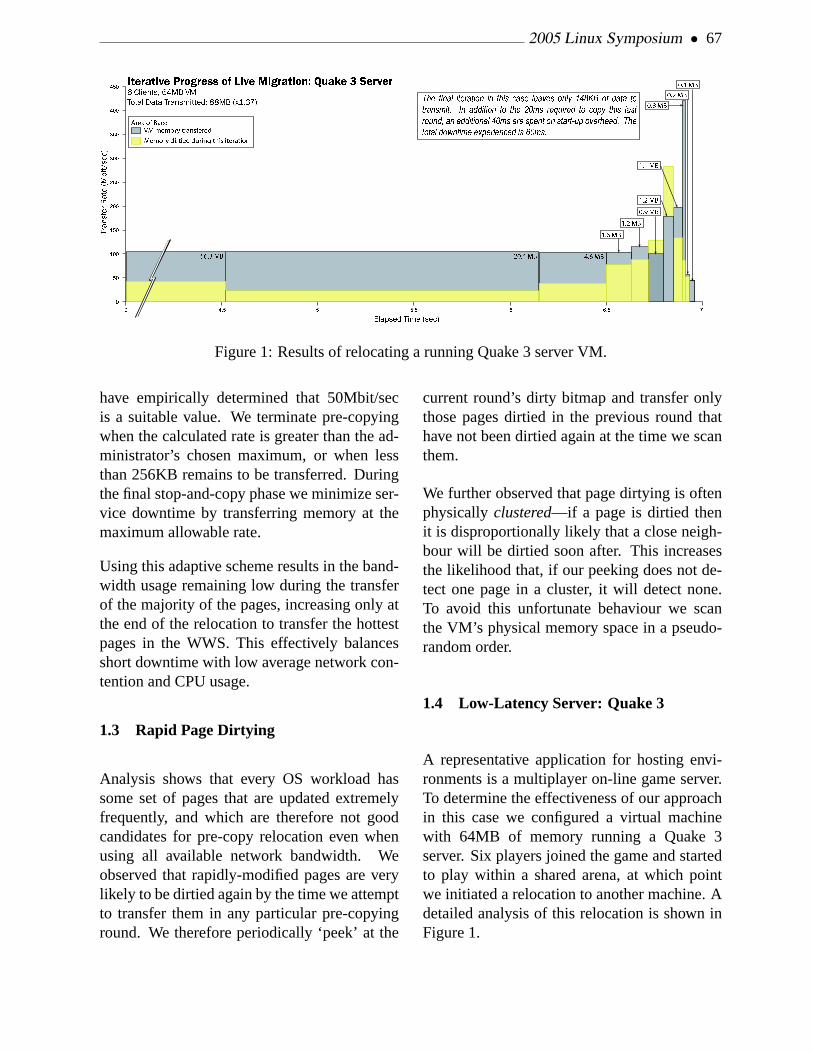
2005 Linux Symposium • 67
Figure 1: Results of relocating a running Quake 3 server VM.
have empirically determined that 50Mbit/secis a suitable value. We terminate pre-copyingwhen the calculated rate is greater than the ad-ministrator’s chosen maximum, or when lessthan 256KB remains to be transferred. Duringthe final stop-and-copy phase we minimize ser-vice downtime by transferring memory at themaximum allowable rate.
Using this adaptive scheme results in the band-width usage remaining low during the transferof the majority of the pages, increasing only atthe end of the relocation to transfer the hottestpages in the WWS. This effectively balancesshort downtime with low average network con-tention and CPU usage.
1.3 Rapid Page Dirtying
Analysis shows that every OS workload hassome set of pages that are updated extremelyfrequently, and which are therefore not goodcandidates for pre-copy relocation even whenusing all available network bandwidth. Weobserved that rapidly-modified pages are verylikely to be dirtied again by the time we attemptto transfer them in any particular pre-copyinground. We therefore periodically ‘peek’ at the
current round’s dirty bitmap and transfer onlythose pages dirtied in the previous round thathave not been dirtied again at the time we scanthem.
We further observed that page dirtying is oftenphysicallyclustered—if a page is dirtied thenit is disproportionally likely that a close neigh-bour will be dirtied soon after. This increasesthe likelihood that, if our peeking does not de-tect one page in a cluster, it will detect none.To avoid this unfortunate behaviour we scanthe VM’s physical memory space in a pseudo-random order.
1.4 Low-Latency Server: Quake 3
A representative application for hosting envi-ronments is a multiplayer on-line game server.To determine the effectiveness of our approachin this case we configured a virtual machinewith 64MB of memory running a Quake 3server. Six players joined the game and startedto play within a shared arena, at which pointwe initiated a relocation to another machine. Adetailed analysis of this relocation is shown inFigure 1.

68 • Xen 3.0 and the Art of Virtualization
Elapsed time (secs)0 10 20 30 40 50 60 70
Pack
et fli
ght tim
e (
secs
)
0
0.02
0.04
0.06
0.08
0.1
0.12
Packet interarrival time during Quake 3 migration
Mig
ratio
n 1
dow
ntim
e: 50m
s
Mig
ratio
n 2
dow
ntim
e: 48m
s
Figure 2: Effect on packet response time of relocating a running Quake 3 server VM.
We were able to perform the live relocationwith a total downtime of 60ms. To determinethe effect of relocation on the live players, weperformed an additional experiment in whichwe relocated the running Quake 3 server twiceand measured the inter-arrival time of packetsreceived by clients. The results are shown inFigure 2. As can be seen, from the client pointof view relocation manifests itself as a transientincrease in response time of 50ms. In neithercase was this perceptible to the players.
2 Device Virtualization
Xen’s strong isolation guarantees have provedvery useful in solving two major problems withdevice drivers: driver availability and reliabil-ity. Xen is capable of allowing individual vir-tual machines to have direct access to specificpieces of hardware. We have taken the ap-proach of using a single virtual machine to runthe physical driver for a device (such as a diskor network interface) and then export a virtu-alized version of the device to all of the otherguestOSes that are running on the host. Thisapproach means that a device need only besupported on a single platform (Linux, for in-stance), and may be available to all the OSes
that Xen runs. Each guest implements an ide-alized disk and network device, which are ca-pable of connecting to the hardware specificdriver in an isolateddevice domain. This ap-proach has the added benefit of making drivers,which are a major source of bugs in operatingsystems, more reliable. By running a driver inits own VM , driver crashes are limited to thedriver itself—other applications may continueto run. Device domains can even be rebootedto recover failed drivers, and result in down-times on the order of hundreds of milisecondsin cases where the entire machine would previ-ously have crashed completely.
This approach will no doubt sound familiarto anyone who has worked with microkernelsin the past—Xen’s isolation achieves a similarfragmentation ofOS subsystems. One majordifference between Xen and historical work onmicrokernels is that we have forgone the archi-tecturally pure fixation on IPC mechanisms infavour of a generalized, shared-memory ring-based communication primitive that is able toachieve very high throughputs by batching re-quests.
To achieve driver isolation, we restrict ac-cess privileges to device I/O registers (whethermemory-mapped or accessed via explicit I/O

2005 Linux Symposium • 69
ports) and interrupt lines. Furthermore, whereit is possible within the constraints of existinghardware, we protect against device misbehav-ior by isolating device-to-host interactions. Fi-nally, we virtualize the PC’s hardwareconfig-uration space, restricting each driver’s view ofthe system so that it cannot see resources that itcannot access.
2.1 I/O Registers
Xen ensures memory isolation amongst do-mains by checking the validity of address-spaceupdates. Access to a memory-mapped hard-ware device is permitted by extending thesechecks to allow access to non-RAM pageframes that contain memory-mapped registersbelonging to the device. Page-level protectionis sufficient to provide isolation because reg-ister blocks belonging to different devices areconventionally aligned on no less than a pageboundary.
In addition to memory-mapped I/O, many pro-cessor families provide an explicit I/O-accessprimitive. For example, the x86 architectureprovides a 16-bit I/O port space to which accessmay be restricted on a per-port basis, as speci-fied by an access bitmap that is interpreted bythe processor on each port-access attempt. Xenuses this hardware protection by rewriting theport-access bitmap when context-switching be-tween domains.
2.2 Interrupts
Whenever a device’s interrupt line is assertedit triggers execution of a stub routine withinXen rather than causing immediate entry intothe domain that is managing that device. Inthis way Xen retains tight control of the sys-tem by schedulingexecution of the domain’s
interrupt service routine (ISR). Taking the in-terrupt in Xen also allows a timely acknowl-edgement response to the interrupt controller(which is always managed by Xen) and allowsthe necessary address-space switch if a differ-ent domain is currently executing. When thecorrect domain is scheduled it is delivered anasynchronousevent notificationwhich causesexecution of the appropriate ISR.
Xen notifies each domain of asynchronousevents, including hardware interrupts, via ageneral-purpose mechanism calledevent chan-nels. Each domain can be allocated up to 1024event channels, each of which comprises a pairof bit flags in a memory page shared betweenthe domain and Xen. The first flag is used byXen to signal that an event ispending. When anevent becomes pending Xen schedules an asyn-chronous upcall into the domain; if the domainis blocked then it is moved to the run queue.Unnecessary upcalls are avoided by triggeringa notification only when an event first becomespending: further settings of the flag are then ig-nored until after it is cleared by the domain.
The second event-channel flag is used by thedomain to mask the event. No notificationis triggered when a masked event becomespending: no asynchronous upcall occurs anda blocked domain is not woken. By settingthe mask before clearing the pending flag, adomain can prevent unnecessary upcalls forpartially-handled event sources.
To avoid unbounded reentrancy, a level-triggered interrupt line must be masked at theinterrupt controller until all relevant deviceshave been serviced. After handling an event re-lating to a level-triggered interrupt, the domainmust calldown into Xen to unmask the inter-rupt line. However, if an interrupt line is notshared by multiple devices then Xen can usu-ally safely reconfigure it as edge-triggering, ob-viating the need for unmask downcalls.

70 • Xen 3.0 and the Art of Virtualization
When an interrupt line is shared by multiplehardware devices, Xen must delay unmaskingthe interrupt until a downcall is received fromevery domain that is managing one of the de-vices. Xen cannot guarantee perfect isolationof a domain that is allocated a shared interrupt:if the domain never unmasks the interrupt thenother domains can be prevented from receiv-ing device notifications. However, shared in-terrupts are rare in server-class systems whichtypically contain IRQ-steering and interrupt-controller components with enough pins for ev-ery device. The problem of sharing is set todisappear completely with the introduction ofmessage-based interrupts as part of PCI Ex-press [1].
2.3 Device-to-Host Interactions
As well as preventing a device driver from cir-cumventing its isolated environment, we mustalso protect against possible misbehavior of thehardware itself, whether due to inherent designflaws or misconfiguration by the driver soft-ware. The two general types of device-to-hostinteraction that we must consider are assertionof interrupt lines, and accesses to host memoryspace.
Protecting against arbitrary interrupt assertionis not a significant issue because, except forshared interrupt lines, each hardware device hasits own separately-wired connection to the in-terrupt controller. Thus it is physically impossi-ble for a device to assert any interrupt line otherthan the one that is assigned to it. Furthermore,Xen retains full control over configuration ofthe interrupt controller and so can guard againstproblems such as ‘IRQ storms’ that could becaused by repeated cycling of a device’s inter-rupt line.
The main ‘protection gap’ for devices, then, isthat they may attempt to access arbitrary ranges
of host memory. For example, although a de-vice driver is prevented from using the CPUto write to a particular page of system mem-ory (perhaps because the page does not belongto the driver), it may instead program its hard-ware device to perform a DMA to the page.Unfortunately there is no good method for pro-tecting against this problem with current hard-ware as it is infeasible for Xen to validate theprogramming of DMA-related device registers.Not only would this require intimate knowl-edge of every device’s DMA engine, it alsowould not protect against bugs in the hardwareitself: buggy hardware would still be able to ac-cess arbitrary system memory.
A full implementation of this aspect of our de-sign requires integration of an IOMMU intothe PC chipset—a feature that is expected tobe included in commodity chipsets in the verynear future. Similar to the processor’s MMU,this translates the addresses requested by a de-vice into valid host addresses. Inappropriatehost addresses are not accessible to the de-vice because no mapping is configured in theIOMMU. In our design, Xen would be respon-sible for configuring the IOMMU in responseto requests from domains. The required val-idation checks are identical to those requiredfor the processor’s MMU; for example, to en-sure that the requesting domain owns the pageframe, and that it is safe to permit arbitrarymodification of its contents.
2.4 Hardware Configuration
The PCI standard defines a genericconfigu-ration spacethrough which PC hardware de-vices are detected and configured. Xen restrictseach domain’s access to this space so that it canread and write registers belonging only to a de-vice that it owns. This serves a dual purpose:not only does it prevent cross-configuration ofother domains’ devices, but it also restricts the

2005 Linux Symposium • 71
domain’s view so that a hardware probe detectsonly devices that it is permitted to access.
The method of access to the configurationspace is system-dependent, and the most com-mon methods are potentially unsafe (eitherprotected-mode BIOS calls, or a small I/O-port ‘window’ that is shared amongst all devicespaces). Domains are therefore not permitteddirect access to the configuration space, but areforced to use a virtualized interface provided byXen. This has the advantage that Xen can per-form arbitrary validation and translation of ac-cess requests. For example, Xen disallows anyattempt to change the base address of an I/O-register block, as the new location may conflictwith other devices.
2.5 Device Channels
Guest OSs access devices viadevice channellinks with isolated driver domains (IDDs). Thechannel is a point-to-point communication linkthrough which each party can asynchronouslysend messages to the other. Channels are estab-lished by using a privilegeddevice managertointroduce an IDD to a guest OS, and vice versa.To facilitate this, the device manager automati-cally establishes an initial control channel witheach domain that it creates. Figure 3 shows aguest OS requesting a data transfer through adevice channel. The individual steps involvedare discussed later in this section.
Xen itself has no concrete notion of a controlor device channel. Messages are communi-cated via shared memory pages that are allo-cated by the guest OS but are simultaneouslymapped into the address space of the IDD or de-vice manager. For this purpose, Xen permits re-strictedsharingof memory pages between do-mains.
The sharing mechanism provided by Xen dif-fers from traditional application-level shared
Figure 3: Using device channel to request adata transfer.
memory in two key respects: shared mappingsare asymmetricand transitory. Each page ofmemory is owned by at most one domain at anytime and, with the assistance of Xen and thedevice manager, that owner may force reclama-tion of mappings from within other misbehav-ing domains.
To add a foreign mapping to its address space,a domain must present a validgrant refer-ence to Xen in lieu of the page number. Agrant reference comprises the identity of thedomain that is granting mapping permission,and an index into that domain’s privategranttable. This table contains tuples of the form(grant,D,P,R,U) which permit domainD tomap pageP into its address space; assertingthe boolean flagR restrictsD to read-only map-pings. The flagU is written by Xen to indicatewhetherD currently mapsP (i.e., whether thegrant tuple isin use).
When Xen is presented with a grant reference(A,G) by a domainB, it first searches for in-dexG in domainA’s active grant table(AGT),a table only accessible by Xen. If no match isfound, Xen reads the appropriate tuple from do-main A’s grant table and checks thatT=grant

72 • Xen 3.0 and the Art of Virtualization
andD=B, and thatR=false if B is requesting awritable mapping. Only if the validation checksare successful will Xen copy the tuple into theAGT and mark the grant tuple as in use.
Xen tracks grant references by associating a us-age count with each AGT entry. When a foreignmapping is created with reference to an existingAGT entry, Xen increments its count. The grantreference cannot be reallocated or reused by thegranting domain until the foreign domain de-stroys all mappings that were created with ref-erence to it.
Although it is clear that this mechanism allowsstrict checking of foreign mappings when theyare created, it is less obvious how these map-pings might be revoked. For example, if afaulty IDD stops responding to service requeststhen guest OSs could end up owning unusablememory pages. We handle the possibility ofdriver failure by taking a deadline-based ap-proach: if a guest observes that a grant tableentry is still marked as in use when it deter-mines that it ought to have been relinquished(e.g., because it requested that the device chan-nel should be destroyed), then it signals a po-tential domain failure to the device manager.
The device manager checks whether the speci-fied grant reference exists in the notifying do-main’s AGT and, if so, sets a deadline bywhich the suspect domain must relinquish thestale mappings. If a registered deadline passesbut stale mappings still exist then Xen notifiesthe device manager. At this point the devicemanager may choose to destroy and restart thedriver, thereby forcibly reclaiming the foreignmappings.
2.6 Descriptor Rings
I/O descriptor rings are used for asynchronoustransfers between a guest OS and an IDD. Ring
updates are based around two pairs of producer-consumer indexes: the guest OS places servicerequests onto the ring, advancing a request-producer index, while the IDD removes theserequests for handling, advancing an associatedrequest-consumer index. Responses are queuedonto the same ring as requests, albeit with theIDD as producer and the guest OS as consumer.A unique identifier on each request/response al-lows reordering if the IDD so desires.
The guest OS and IDD use a sharedinter-domain event channel to send asynchronousnotifications of queued descriptors. An inter-domain event channel is similar to the interrupt-attached channels described in Section 2.2. Themain differences are that notifications are trig-gered by the domain attached to the oppositeend of the channel (rather than Xen), and thatthe channel isbidirectional: each end may in-dependently notify or mask the other.
We decouple the production of requests or re-sponses on a descriptor ring from the notifica-tion of the other party. For example, in the caseof requests, a guest may enqueue multiple en-tries before notifying the IDD; in the case ofresponses, a guest can defer delivery of a noti-fication event by specifying a threshold numberof responses. This allows each domain to in-dependently balance its latency and throughputrequirements.
2.7 Data Transfer
Although storing I/O data directly within ringdescriptors is a suitable approach for low-bandwidth devices, it does not scale to high-performance devices with DMA capabilities.When communicating with this class of de-vice, data buffers are instead allocated out-of-band by the guest OS and indirectly referencedwithin I/O descriptors.

2005 Linux Symposium • 73
When programming a DMA transfer directly toor from a hardware device, the IDD must firstpin the data buffer. We enforce driver isolationby requiring the guest OS to pass a grant ref-erence in lieu of the buffer address: the IDDspecifies this grant reference when pinning thebuffer. Xen applies the same validation rules topin requests as it does for address-space map-pings. These include ensuring that the mem-ory page belongs to the correct domain, andthat it isn’t attempting to circumvent memory-management checks (for example, by request-ing a device transfer directly into its page ta-bles).
Returning to the example in Figure 3, theguest’s data-transfer request includes a grantreferenceGR for a buffer pageP2. The requestis dequeued by the IDD which sends a pin re-quest, incorporating GR, to Xen. Xen reads theappropriate tuple from the guest’s grant table,checks thatP2 belongs to the guest, and copiesthe tuple into the AGT. The IDD receives theaddress ofP2 in the pin response, and then pro-grams the device’s DMA engine.
On systems with protection support in thechipset (Section 2.3), pinning would trigger al-location of an entry in the IOMMU. This isthe only modification required to enforce safeDMA. Moreover, this modification affects onlyXen: the IDDs are unaware of the presence ofan IOMMU (in either case pin requests returna bus address through which the device can di-rectly access the guest buffer).
2.8 Device Sharing
Since Xen can simultaneously host many guestOSs it is essential to consider issues arisingfrom device sharing. The control mechanismsfor managing device channels naturally sup-port multiple channels to the same IDD. We
describe below how our block-device and net-work IDDs support multiplexing of service re-quests from different clients.
Within our block-device driver we servicebatchesof requests from competing guests ina simple round-robin fashion; these are thenpassed to a standard elevator scheduler be-fore reaching the disc controller. This bal-ances good throughput with reasonably fair ac-cess. We take a similar approach for networktransmission, where we implement a credit-based scheduler allowing each device channelto be allocated a bandwidth share of the formx bytes everyy microseconds. When choosinga packet to queue for transmission, we round-robin schedule amongst all the channels thathave sufficient credit.
A shared high-performance network-receivepath requires careful design because, withoutdemultiplexing packets in hardware [2], it is notpossible to DMA directly into a guest-suppliedbuffer. Instead of copying the packet into aguest buffer after performing demultiplexing,we insteadexchange ownershipof the pagecontaining the packet with an unused page pro-vided by the guest OS. This avoids copying butrequires the IDD to queue page-sized buffersat the network interface. When a packet isreceived, the IDD immediately checks its de-multiplexing rules to determine the destinationchannel—if the guest has no pages queued toreceive the packet, it is dropped.
3 Supporting Unmodified OSes
Xen’s original goal was to provide fast virtu-alization, which was achieved by ‘paravirtual-izing’ guest OSes. The downside of paravirtu-alization is that it requires modification of theguest OS source code—an approach which isuntenable for closed-source operating systems.

74 • Xen 3.0 and the Art of Virtualization
The alternative, full virtualization of the hard-ware platform, has traditionally been very diffi-cult on the x86 processor architecture. How-ever, new processor extensions promised byAMD and Intel provide hardware assistancewhich makes full virtualization much easier toprovide.
Preliminary support for Intel VirtualizationTechnology for x86 processors (VT-x) is al-ready checked into the Xen repository. Thisprovides a ‘virtual processor’ abstraction to theguest OS which, for example, can transparentlynotify Xen of any attempt to execute instruc-tions that would modify privileged processorstate. While these hardware extensions maketransparent virtualization easier, Xen still bearsresponsibility for device management and en-forcing isolation of shared resources such asCPU time and memory.
3.1 VT-x architecture overview
VT-x augments the x86 architecture with twonew forms of CPU operation: VMX root opera-tion and VMX non-root operation. Xen runs inVMX root operation, while guests run in VMXnon-root operation. Both forms of operationsupport all four privilege levels (rings 0 through3), allowing a guest OS to appear to run at itsusual ‘most privileged’ level. VMX root oper-ation is similar to x86 without VT-x. Softwarerunning in VMX non-root operation is depriv-ileged in certain ways, regardless of privilegelevel.
VT-x defines two new transitions: aVM en-try that transitions from Xen root operation toguest non-root operation, and aVM exitwhichdoes the opposite transition. Both VM entriesand VM exits load CR3 (the base address ofthe page-table hierarchy) allowing Xen and theguest to run in different address spaces. VT-x also defines a virtual-machine control struc-
ture (VMCS) that manages VM entries and ex-its and defines processor behavior during non-root execution.
Processor behavior changes substantially inVMX non-root operation. Most importantly,many instructions and events cause VM exits.Some instructions cannot be executed in VMXnon-root operation because they cause VMexits unconditionally; these include CPUID,MOV from CR3, RDMSR, and WRMSR.Other instructions, interrupts, and exceptionscan be configured to cause VM exits condition-ally, using VM-execution control fields in theVMCS.
VM entry loads processor state from the guest-state area of the VMCS. Xen can optionallyconfigure VM entry to inject an interrupt or ex-ception. The CPU effects this injection usingthe guest IDT, just as if the injected event hadoccurred immediately after VM entry. This fea-ture removes the need for Xen to emulate de-livery of these events. VM exits save processorstate into the guest-state area and load proces-sor state from the host-state area. All VM exitsuse a common entry point into Xen. To sim-plify the design of Xen, every VM exit savesinto the VMCS detailed information specifyingthe reason for the exit; many exits also recordan exit qualification, which provides further de-tails.
3.2 VT-x Support in Xen
The three major components for adding supportof VT-x and running unmodified OS in Xen are:
1. Extensions to the Xen hypervisor
2. Device models that emulate the PC plat-form
3. Administrator control panel

2005 Linux Symposium • 75
The hypervisor extensions involve adding sup-port for the specific hardware features and in-struction opcodes added by VT-x, and exten-sions to the user-space control tools for build-ing and controlling fully-virtualized guests.Device models provide emulation of the PCplatform devices for a VMX domain. Thesoftware models emulate all the hardware-levelprogramming interfaces that a normal devicedriver uses to perform I/O operation, and sub-mit requests to a physical device on the VMXdomain’s behalf.
QEMU and Bochs are two open source PC plat-form emulators that provided most of the func-tionality we needed for I/O emulation for VMXdomains. Our basic design has been to run thedevice models in domain 0 user space and runone process for each VMX domain. We neededto remove all CPU emulation code from theseemulators and modify the code that emulatedphysical memory (RAM). Normally, they allo-cate a large array to emulate the physical mem-ory. We modified the code to map all the phys-ical memory allocated to the VMX domain.
An example of I/O request handling from VMXguest is as follows:
1. VM exit due to an I/O access.
2. Xen decodes the instruction.
3. Xen constructs an I/O request describingthe event.
4. Xen sends the request to the device-modelprocess in domain 0.
5. When reading from a device register, theVMX domain is blocked until a responseis received from the device model.
4 New Architectures
Xen was originally designed and implementedto support the x86 architecture. As interest inXen has increased, several organisations haveexpressed interest in using Xen as a commonhypervisor for other hardware platforms. Thelast year has seen fervent development of ar-chitectural support for both x86/64 and IA-64.
In addition to x86/64 and IA-64, ports of Xenare underway to the IBM Power platform andto both of the upcoming fully virtualized ver-sions of x86, Intel’s VT (described in the pre-vious section) and AMD’s Pacifica/SVM. Ourexperience with IA-64 supports our belief thatXen will successfully accommodate these newarchitectures and any others that come along inthe future.
4.1 x86/64
When extending Xen to support the x86/64 ar-chitecure, we kept in mind that the platformis largely identical to x86/32, differing only insome of the details of the processor architec-ture. For example, processor registers are ex-tended to 64 bits and the page-table format isextended to support the larger address space.Fortunately, the hardware platfrom is largelyidentical: for example, sharing the same I/Obus and chipset implementations.
This led us to implement x86/64 support asa sub-architecture of the existing x86 target.Large swathes of code are shared between sub-architectures, with the main differences beingin assembly-code stubs and page-table manage-ment.
From a guest perspective, the most interest-ing change presented by x86/64 is the modi-fied protection model. x86/64 provides verylimited segment-level protection which makes

76 • Xen 3.0 and the Art of Virtualization
it impossible to protect the hypervisor, runningin ring 0, from a guest kernel running in ring 1.This architectural change necessitates runningboth the guest kernel and applications in ring 3,and raises the problem of protecting one fromthe other.
The solution is to run the guest kernel in a dif-ferent address space (i.e., on different page ta-bles) from its applications. When forking anew process, the guest kernel creates two newpage tables: one that is used in applicationcontext, and the other in kernel context. Thekernel page table contain all the same map-pings as the application page table but also in-clude a mapping of the kernel address space.All transitions between application and guest-kernel contexts must pass via Xen, which au-tomatically switches between the two page ta-bles.
4.2 IA-64
As of this writing, Xen/ia64 is between its al-pha release and beta release. All basic hy-pervisor capability is present: Domain 0 runssolidly as a ‘demoted’ guest OS, utilizing alldevices while booting to a full graphical con-sole and executing all Linux/ia64 applicationsunchanged. Multiple guest domains can belaunched, but virtual I/O functionality is notfinished so any unprivileged domain boots tothe point where init fails to find a root disk, thenpanics and reboots in an infinite cycle. SMPsupport is not yet present, either in the hypervi-sor itself or in the guest.
Full functionality in Xen/ia64 is expected laterthis year, but the port is sufficiently complete toillustrate some similarities and differences thatestablish credibility that Xen will prove widelyportable:
1. Hardware-walked page tables must be
carefully managed in Xen/x86 and, in-deed, handling page tables is one of themost complex parts of Xen, requiring afair amount of code in the hypervisor andnon-trivial changes in the paravirtualiza-tion of guests. On ia64, hardware page-table walking is still necessary for per-formance, but can be much more easilydiverted to hypervisor-managed page ta-bles. The difference is completely hiddenfrom common code and implemented inthe arch-specific layer.
2. Like the x86 architecture, ia64 is notfully virtualizable—certain instructionshave different results when executed atdifferent privilege levels. Both Xen archi-tectures ‘demote’ the guest OS and pro-vide an interface to handle these privilege-sensitive operations.
3. While the x86 has a small state vector, theia64 architecture has well over 500 regis-ters and two stacks that must be carefullymanaged for each thread. Linux solvesthis elegantly with multiple state stagingareas and lazy save/restore to optimizekernel entry and exit and thread switching.Recognizing the similarity between Linuxthreads and Xen domains allows most ofthe Linux code to be directly reusable.
4. The page size on x86 is 4kB. Modern ver-sions of x86 chips support a larger pagesize, but its use is limited. IA-64 sup-ports nine different page sizes and a guestOS may use all of them simultaneously.Thus, Xen/ia64 must manage this addi-tional complexity. Again, this is safelyhidden in Xen through asm macros andarch-specific modules.

2005 Linux Symposium • 77
5 Conclusion
In this paper, we have presented a briefoverview of the major new features in Xen 3.0including VM relocation, device driver isola-tion, support for unmodified operating systems,and new hardware support for both x86/64 andIA-64 processors. Xen is quickly maturing intoan enterprise-class VMM and is currently be-ing used in production environments around theglobe.
References
[1] PCI Express base specification 1.0a.PCI-SIG, 2002.
[2] I. Pratt and K. Fraser. Arsenic: AUser-Accessible Gigabit EthernetInterface. InProceedings of IEEEINFOCOM-01, pages 67–76, April 2001.

78 • Xen 3.0 and the Art of Virtualization

Examining Linux 2.6 Page-Cache Performance
Sonny Rao, Dominique Heger, Steven PrattIBM Corporation
{sonnyrao, dheger, slpratt}@us.ibm.com
Abstract
Given the current trends towards ubiquitous64-bit server/desktop computing with largeamounts of cheap system memory, the perfor-mance and structure of the LinuxR© page-cachewill undoubtedly become more important in thefuture. An empirical and analytical examina-tion of performance will be valuable in guidingfuture development.
The current 2.6 radix-tree based design repre-sents a huge leap forward from the old globalhash-table design, but there may be some issueswith the current radix-tree structure itself.
The main goal is to understand performanceof the current implementation, examine per-formance with respect to other potential data-structures, and look at ways to improve concur-rency.
1 The Radix-Tree based PageCache in Linux 2.6
The Linux 2.6 page cache is basically a collec-tion of pages that normally belong to files. Thepages are kept in memory for performance rea-sons. As on other UNIXR© operating systems,the page cache may take up the majority of theavailable memory. Whenever a thread reads
from or writes to a file, takes a page fault, oris paged out, the page cache becomes involved.Hence, the performance of the page cache hasa rather dramatic impact on the performance ofthe system. As a particular page is referenced,the page cache has to be able to locate the page,or has to determine that the page is not in thecache, in as efficient and effective way as possi-ble with a focus on minimal memory overhead.
1.1 Evolution of the Page Cache
In older versions the Linux kernel utilized aglobal hash-table based approach to maintainthe pages in the cache. The hash based ap-proach had some performance issues:
1. A hash key is normally not unique; hencethe system has to resolve collisions. Ahash chain had to be built to hold entries(each entry used up 8 bytes per referencedpage).
2. A single global lock governed the pagecache; causing scalability issues on SMPbased systems.
The radix-tree based page cache solution ad-dresses the issues discussed above.
Technically, the Linux 2.6 system consists ofmany smaller page cache subsystems, or more
• 79 •

80 • Examining Linux 2.6 Page-Cache Performance
specifically, one for each open file in the sys-tem.
Segregating page caches has a few advantages:
First, each page cache can have its own lock,avoiding the global page cache lock that wasnecessary in older versions.
Second, search operations work on a smalleraddress space, and complete more quickly.
Third, as there is one page cache per open file,the only index required to look up a specificpage is the offset within the file.
In the radix-tree, the 32-bit or 64-bit file off-set is divided into subsets whose size is basedon the value ofMAP_SHIFT as defined inlib/radix.c. The current implementation usesa MAP_SHIFT of six for 6-bit indices. Thehighest-order sub-field (or set) is used to branchinto a 64-entry table in the root of the radix-tree. An entry in that sub-table serves as apointer to the next node in the tree. The nextlower sub-field (from the index) is used to in-dex that particular node, yielding a third ab-straction. Eventually, the algorithm will reachthe bottom of the tree and obtain the actual pagepointer or finds an empty entry, signifiying thatthe page is not present. Table 2 shows maxi-mum file offset and number of pages versus treeheight for the shift value of six.
There is some precedent for using a value otherthan six for theMAP_SHIFT. Originally, sevenwas used for theMAP_SHIFTwhen the struc-ture was first introduced [7]. Larger valuesmean smaller trees in terms of height and thepossiblity of shorter search times. This possi-bility comes at the expense of bigger nodes inthe slab cache, which means that there is morepotential for wasted entries.
Shift through- delta profile deltaput
6 4.61 N/A 13.21 N/A8 4.745 (+3)% 12.09 (–8.7)%
10 4.705 (+2)% 12.40 (–6.14)%12 4.695 (+1.8)% 12.31 (–6.72)%4 4.683 (+1.6)% 17.22 (+30.4)%
Table 1. Sequential read throughput andpercent of profile ticks forradix_tree_lookup results for different values ofMAP_SHIFT . The units for throughput are GB/sec,and the profile column represents time spent inradix_tree_lookup . These values repre-sent the average of four runs.
height maximum maximumpages file
offset0 0 01 64 256 KB2 4096 16 MB3 262144 1 GB4 16777216 64 GB5 1073741823 4 TB6 4294967296 16 TB
Table 2. Max number of pages by radix-treeheight with a 32-bit key andMAP_SHIFTof 6,file offset assumes 4k pages
One optimization criterion was to ensure thatthe radix-tree would only be as deep as nec-essary. In the case where the system operateson small files (smaller than 65 pages), only onelevel of abstraction (one node) will be used. Inother words, only the least significant sub-fieldof the offset is being utilized. This property ofthe current implementation allows the normallydetrimental effects of a large key on a radix-tree to be minimized. The only potential down-side is in the case of a sparse file where nodeslocated at relatively large offsets will force ahigher tree depth than might otherwise be nec-essary.

2005 Linux Symposium • 81
1.2 Newer Features in 2.6
One of the newer features incorporated inLinux revolves around ‘tagging’ dirty pages inthe radix-tree. In other words, a dirty page isonly flagged in the radix-tree, and not movedto a separate list as in the pre 2.6.6 design.Along the same lines, pages that are being writ-ten back to disk are flagged as well. A newset of radix-tree functions was implemented tolocate these pages as necessary. Searching anentire tree structure for these pages is not asefficient as just traversing trough a dedicatedlist, but based on the feedback from the Linuxcommunity, the performance delta is not con-sidered a big issue. There is some concern inthe Linux community that with very large filesthe 2.6 lock-per-file based approach will be asbad as the global lock based 2.4 implementa-tion. The tagging of these pages in the newdesign required a lot of changes to the pagecache and the VM subsystems, respectively.One implication of the changes is that the dirtypages are now always written in file offset or-der out to disk. As the Linux community re-ports, this may cause some performance issuesinvolving parallel write() operations on largeSMP systems. The tagging of all these pagesin the radix-tree contributes to the complexityof switching from a radix-tree based approachto another data structure (if needed). Basedon the current implementation, improving theradix-tree seems more feasible than a completere-design and should therefore be explored first.TheMAP_SHIFTparameters in the radix codereveal some potential for performance work.
There is a scalability issue when dealing withonly a small amount of very large files and aworkload that consists of many concurrent readoperations on the files. The single lock govern-ing the radix-tree will basically eliminate anypotential scalability on SMP systems while ex-posed to such a workload. Scalability of courseis achieved when the workload consists of n
worker threads reading from n separate files,hence the locking is distributed over the set offiles being accessed. Table 3 shows the sever-ity of the locking problems of the current spin-lock design vs the rwlock design and shows thateven the rwlock implementation spends a gooddeal of time overall CPU time in locking func-tions.
Table 3 shows throughput on an IBM p650 8-CPU POWER4+ server with 16GB of RAMand two 7GB files fully cached with differingnumbers of threads attempting to sequentiallyread the files. Throughput is in GB/sec andthe profile columns show the percentage of timefrom the profile spent in locking functions.
Threads Spinlock Profile Rwlock Profile1 1.11 0.10% 1.04 0.80%4 2.26 12.4% 2.47 4.33%8 2.01 54.1% 2.82 9.75%
12 2.20 51.6% 2.98 9.86%14 2.31 49.3% 3.03 9.74%16 2.34 48.9% 3.13 9.52%
Table 3. Read throughput and time spent inlock functions for spinlock and rwlock kernels.
There has been some ongoing debate overwhether a rwlock solution would be more ac-ceptable, however as of this writing it has beenheld out of mainline due to specific concernsover the performance of the rwlock solution onPentium-4 machines [9, 10]. Although the costof locking is substantial on all architectures,this architecture seems to exhibit particularlyhigh latency on the unlock operation. This alsoseems to indicate that the radix-nodes tend tobe cached and that search times are small [8].
2 Alternative Data-Structures
Given the unique nature of the radix implemen-tation in the Linux kernel, comparative analysis

82 • Examining Linux 2.6 Page-Cache Performance
of the radix-tree with alternative data-structuresshould provide insights into its strengths andweaknesses. In general, for the application ofpage-cache lookup, speed should be paramountsince in the case of a cache hit, the entire read orwrite operation should occur at memory speed.Inserts, on the other hand, will typically be fol-lowed by disk I/O, and that I/O should becomethe limiting factor for the operation rather thanthe cache update. Deletes are initiated from atruncate operation or by the page-scanner whenthe system is under memory pressure. Thiscase of memory pressure is performance crit-ical since the VM wants to release the pagesselected as soon as possible, and updates tothe caching structures represent pure overhead.Operations such as “tagging” pages as dirtyare also interesting because they involve botha lookup and a modification to the state of thedata structure. However this operation is spe-cific to the Linux 2.6 radix-tree implementationand is not available on all data-structures. Insome cases it may be possible to graft these ad-ditional pieces of state information onto otherstandard data-structures, but it is not practicalin all cases.
Given these qualities, it seemed appropriate totest the Linux kernel implementation of radix-trees against a number of other data-structureseach with slightly different design trade-offs.
2.1 Extendible-Hashing
One idea suggested was that of extendible-hashing, which is a technique developed foroptimizing lookup operations in database sys-tems [6]. Among other interesting properties,extendible hashing guarantees that data can beaccessed in just two “page-faults” in databaseterminology, which translates to two pointerdereferences for our purposes. As the namesuggests, it is capable of extending itself as theamount of data stored increases, and it can do
this without costly re-hashing of the entire data-set. Conversely, the extendible hash-table canbe implemented to contract itself as elementsare removed. Naturally, these characteristicsare not free and represent a trade-off for thefixed number of memory dereferences in thelookup path.
The extendible hash-table typically is imple-mented using two structures: buckets, whichcontain the pointers to the data, and a directory,which contains the pointers to the buckets. Thedirectory is just a large array with a power-of-two size. The logarithm of the current size iscalled the directory depth.
Elements are inserted by computing a hash keyand taking the n most-significant bits of thatkey, where n is equal to the directory depth. Us-ing this value to index into the directory yieldsa pointer to the bucket where the new elementwill reside. Different strategies exist for plac-ing an element into a bucket. Depending on thesize of the bucket, the object’s hash value canbe used again to place the item, or if the bucketis fairly small, a simple linear insert can be ef-fective.
Each pointer in the directory is not necessarilyunique, and there can be mulitple pointers toa certain bucket. For this reason, the bucketskeep a local-depth value, which can be used tocompute the number of pointers to it in the di-rectory. When a bucket becomes full, it mustbe split into two separate buckets in an oper-ation called a bucket-split. After the bucket-split, each new bucket will get half of the oldpointers in the directory, and the local depth ofthe buckets will increase by one. If the buckethas a local depth equal to the directory depth,then the directory must be first doubled in sizebefore the bucket can be split. In this case,there is only one pointer in the directory to thisparticular bucket before the directory doublingoperation, and afterwards there are two point-ers and the bucket-split can proceed. When a

2005 Linux Symposium • 83
bucket-split occurs, the elements in the originalbucket are redistributed into the new buckets insuch a way that their hash-keys will lead to thecorrect bucket from the directory. In this way,the extendible hash-table avoids having to everglobally re-hash and instead limits redistribu-tion to bucket-splits while retaining the originalhash function.
One additional characteristic of the extendible-hashing is its ability to handle random se-quences of keys equally as well as sequentialsequences. Though many typical applicationswill primarily use sequential I/O patterns, someapplications might find this characteristic ben-eficial.
2.2 Threaded Red-Black Tree
Threaded red-black trees are a twist on the no-tion of a traditional red-black tree, which try tooptimize for sequential access sequences by us-ing normally NULL leaf pointers as “threads”which keep track of nodes with neighboringkeys [12]. So, if one already has a referenceto a particular leaf node, access to the previousnode (in terms of key order ) only requires ac-cessing that node’s left “thread.”
The regular red-black tree properties still ap-ply [1,2], but since almost all child pointersare used in some way, additional state informa-tion must be kept in the nodes to differentiatechildren from threads. Luckily, red-black trees,such as the one in the Linux kernel, already usean extra word per node to keep track of color.This extra word can be overloaded to keep trackof thread information as well with no additionalspace cost.
Since one cannot simply test for NULL duringlookups, one must also alter any open-codedlookup sequences to be thread-aware, which isto say such code must examine the state infor-mation in the node. Ideally, this should not be
a significant cost because the flags should typ-ically have reasonable spatial locality with theother pointers in the node and would be kept inthe same cache-line.
As with regular red-black trees, performance ofinserts and deletes is traded off to keep the treebalanced and keep average lookup times down.In the case of the threaded version this is evenmore true as thread information must be keptconsistent through rebalancing operations.
The implementation tested was similar to theLinux kernel’s present red-black tree imple-mentation which assumes the node contents areembedded into another object and passes off re-sponsibility for memory allocation and imple-menting lookups onto the tree’s user.
2.3 Treap
A treap is the basic data structure (BST) under-lying randomized search trees [3]. The nameitself refers to the synthesis of a tree and a heapstructure. More specifically, a treap representsa set of items where each item has associatedwith it a key and a priority. In general a pri-ority is randomly assigned to a given key bythe implementation. A treap represents a spe-cial case of a binary search tree, in which thenode set is arranged in order (with respect tothe keys) as well as in heap fashion with re-gards to the priority. The procedure for lookupin a treap is the same as for a normal binarysearch-tree and the node priorities are simplyignored. In a treap, the access time is propor-tional to the depth of an element in the tree. Aninsert of a new item basically consists of a twostep process. The first step consists of utiliz-ing the item’s key to attach to the treap at theappropriate leaf position, and second to use thepriority of the new element to rotate the new en-try up in the structure until the item locates theparent node that has a larger priority. Interest-ingly, it can be shown in the general case that

84 • Examining Linux 2.6 Page-Cache Performance
an insert will only cause two rotations, whichmeans updates are much less costly then in thecase of a strictly balanced tree such as an AVLtree or red-black tree.
The implementation tested used a simple poly-nomial hash function on the key to generate thepriority. This approach was used instead of thekernel’s random number generator to keep theimplementation as self-contained as possible.
Again, the implementation tested follows theLinux kernel’s convention of assuming the usermust allocate the nodes and open-code thelookup sequences.
2.4 Linux Radix-Tree
The Linux implementation of the radix-tree ishighly optimized and customized for use inthe kernel and differs signifcantly from whatis commonly referred to as a radix-tree [1,4,5]It avoids paying the memory cost of explictlykeeping keys, child-pointers, and separate data-pointers on each object but instead uses implicitordering along with node height to determinethe meaning of these pointers. For example, ifthe tree has a global height of three, then thepointers on the first two levels only point tochild nodes and the lowest level uses its point-ers for data objects. Data pointers only exist atthe lowest level.
By aggressively conserving memory and reduc-ing the tree’s overall size, the radix-tree has anextremely small cache footprint which is vitalto its success at larger tree sizes.
The main disadvantage of using implicit or-dering in the implementation is that a highlysparse file will force the use of more tree-levelsacross the entire tree for all offsets. The cur-rent implementation uses aMAP_SHIFTof sixwhich means sixty-four pointers per node, and
in the worst case all but one of those pointersis wasted from the root all the way down to theleaf. The height is directly related to the offsetof the last object inserted into the tree.
The kernel implementation also supports tag-ging which means each node not only consistsof an array of pointers but a set of bit-fields foreach pointer which can be used somewhat ar-bitrarily by the subsystem utilizing the tree. Inthe case of the page-cache, these tags are usedto keep track of whether a page is dirty or un-dergoing writeback.
The meaning of these tags is clear at the leafnodes, but at higher levels, tags are used to referto the state of any objects in or below the childnode at the corresponding offset.
For example, given a three level radix-tree, andthe page at offset one is dirty, then the dirty-tagfor bit one on the leaf node is set and the tagsfor bit zero are set in the two nodes above. Thisway, gang-lookups searching for tagged nodescan be optimized to skip over subtrees withoutany tagged descendants.
2.5 Analysis
In all three operations tested, there was no sig-nificant difference between the data structuresuntil roughly 128K elements where the differ-ences begin and are highlighted by the remain-ing data points.
The extendible-hashing results were initiallyvery surprising as it seems to perform muchworse than the tree structures at high objectcounts. After analyzing performance counterinformation, it was determined that the ex-tremely poor spatial and temporal locality ofthe the hash directory and buckets were causingTLB and similar translation cache misses andthus large amounts of time were spent doing

2005 Linux Symposium • 85
Figure 1: Sequential Lookup Performance
Figure 2: Sequential Insert Performance

86 • Examining Linux 2.6 Page-Cache Performance
Figure 3: Sequential Delete Performance
page-table walk operations. Also, the poor spa-tial locality caused a great deal of data-cachemisses which compounded the problems. Onthe other hand, for the tree structures, the se-quential nature of the test yielded significantbenefits to their cache interactions.
The two binary-tree structures offer mixed per-formance with generally worse performance onlookups and inserts with only the treap nar-rowly beating the radix-tree in deletes. Thethreaded red-black tree also seems to do worsethan expected in lookups which will requiresome further analysis.
The radix-tree scales extremely well into thevery large numbers of pages because the tree it-self fits into processor caches much better thanthe alternative designs. In the case of the deleteoperations the radix-tree still does well, but isbeaten in some cases by the treap. Most likely,this is because of the extensive updates whichmust occur to the tagging information up thetree which typically would not have good spa-
tial or temporal locality with respect to the ini-tial lookup.
This result has also been observed under a‘real’ data-base workload where theradix_
tree_delete call shows up higher in ker-nel profiles than theradix_tree_lookup op-erations, which was initially rather confus-ing, as it was expected that most of the timein the radix-tree code would be spent doinglookup operations. Table 4 shows this ef-fect, whereradix_tree_delete shows up asthe third highest kernel function andradix_
tree_lookup is number ten. Overall, thisparticular database query is heavily I/O bound,as dedicated_idle represents time spentwaiting on I/O to complete, and the rest of thefunctions indicate memory pressure (shrink_
list , shrink_cache , refill_inactive_
zone , and radix_tree_delete ) and otherfilesystem activity (find_get_block ).

2005 Linux Symposium • 87
DB Workload: Top 10 Kernel Functions
dedicated_idle__copy_tofrom_user
radix_tree_delete_spin_lock_irq
__find_get_blockshrink_list
refill_inactive_zone__might_sleep
shrink_cacheradix_tree_lookup
Table 4: Kernel functions reported by OProfilefrom a standard commercial database bench-mark which simulates a business decision sup-port workload. The tests were run on IBMOpenPower 720 4-CPU machine running onExt3 with 92% of time spent in the kernelfor this query. Other querys in the work-load showed similar results where in all casesradix_tree_delete was ordered higherthanradix_tree_lookup .
2.6 Continuing Work
In the interests of time, all of these resultswere collected in userspace. As time permits,the tests can be re-done using kernel-space im-plementations to keep user-space biases to aminium and to avoid any bias due to the mem-ory allocator.
These tests also represent best-case cache-behavior, because actual data pages were notbeing moved through the memory sub-system.Again, these structures should be re-examinedin the future with a mixed workload with sub-optimal caching behaviors.
3 Going Forward with Improve-ments to the Page-Cache
As far as improving the radix-tree, there doesnot appear to be any reason to outright replacethe current implementation, however perfor-mance could probably be improved for the classof workloads desiring concurrent access to theradix-tree structure by improving the lockingbehaviors for the radix-tree. As an example,a database system using large files for storingtables and using the page-cache could run intothis issue.
3.1 A Lockless Design
Ultimately, it would be beneficial to imple-ment a fully lockless design (for readers) us-ing a Read-Copy-Update (RCU) approach [11].This would allow the tree to better scale withmany concurrent readers, and should not causeany difference in performance for a writers.This could cause a number of issues and race-conditions where readers seeing “stale” datacould cause problems, and these issues must be

88 • Examining Linux 2.6 Page-Cache Performance
fully explored and understood before an imple-mentation can be attempted.
Of the data-structures mentioned above, theradix-tree and the extendible hash-table wouldbe the best structures suited for a lockless de-sign, while the binary-tree structures are some-what more difficult to modify for RCU.
In the case of the extendible hash-table, thereare two cases to consider: bucket-splits anddirectory-expansion. In the case of bucket-splits, two new buckets are typically allocatedto replace the original, so the original could beleft in place for other readers, while the writingthread copied the data from the original bucketto the new ones and then updated the point-ers in the directory. The race between readerslooking at the directory and seeing the origi-nal bucket and seeing one of the new buckets isnot problematic, since in either case, the appro-priate data will be in whichever bucket is seen.The release of the memory for the old bucketwould simply have to wait until all processorshad reached a quiescent state. In the case ofthe directory expansion (or contraction) a sim-ilar technique would apply, where the writingthread works to update the new directory whileleaving the old one in place. Then it can updatethe pointer to the directory after it finishes anduse a deferred release for the old directory.
For the radix-tree, the main update case isradix-tree extension, where a new offset is in-serted which requires an increase in the heightof the tree. Luckily, the radix-tree is fairly sim-ple and does not require complex restructuringin this case, but instead merely adds new levelsontop of the exisiting tree. So, in this case thewriter thread creates these new nodes and setsthem up while letting concurrent readers seethe pre-exisiting tree, then when all of the newradix-nodes are set up, the height of the tree canbe incremented and a new root installed. Thereis one problem with doing this today, the radix-tree root object currently consists of three fields
including the height and a pointer to the root.For the RCU design to work, it must be able toatomically update a single field for the readersto look at, however both the height and the rootpointer require updates. The solution to this isto add another level of indirection and simplykeep that information in a separate dynamic ob-ject.
3.2 An Evolutionary Improvement
An alternative approach using gang-lookups,which is more evolutionary with respect to thecurrent locking design, was suggested by Su-parna Bhattacharya1.
The current locking design works one page ata time where the radix-tree lock is acquiredand released for each page locked. This is onereason why the rwlock approach may not befaster, since it uses an atomic operation bothon acquisition and release whereas a spin-lockonly uses one atomic operation on a success-ful lock acquisition. Her suggestion was to in-stead use a gang-lookup and lock each page re-quested one after the other before releasing thetree-lock. This approach would drastically re-duce the number of costly atomic operations.This would come at the cost of increased lockhold times for the tree, but this could be mit-igated somewhat by going back to the rwlockapproach. Further, in this case the rwlock be-comes a more effective solution since the num-ber of unlock operations is drastically reduced.
method spin-lock rwlockpage by page 2n 3ngang-lookup n + 1 n + 2
1This idea was suggested in a private email to the au-thors, where she is working on converting the write-pathto do something similar

2005 Linux Symposium • 89
Table 5. Table showing number of atomic oper-ations required to lock n pages for the differentlocking strategies.
4 Summary
Overall, the performance of the current Linux2.6 radix-tree is quite good as compared to theother data-structures chosen. Probably the areawhich is most ripe for improvement is the lock-ing strategy for the radix-tree. A few differentalternatives have been suggested, and hopefullyby using these or other approaches, page-cacheperformance can be improved so that it evenbetter than it is today.
5 Legal
Copyrightc© 2005 IBM.
This work represents the view of the authors anddoes not necessarily represent the view of IBM.
IBM and the IBM logo are trademarks or registeredtrademarks of International Business Machines Cor-poration in the United States and/or other countries.
Linux is a registered trademark of Linus Torvalds.
UNIX is a registerd trademark of The Open Group,Ltd. in the United States and other countries.
Other company, product, and service names may betrademarks or service marks of others.
References in this publication to IBM products orservices do not imply that IBM intends to makethem available in all countries in which IBM oper-ates.
Disclaimer: The benchmarks discussed in this paperwere conducted for research purposes only, under
laboratory conditions. Results will not be realizedin all computing environments.
This document is provied “AS IS,” with no expressor implied warranties. Use the information in thisdocument at your own risk.
6 References
[1] Cormen, T.,Algorithms, Second Edition,MIT Press, 2001.
[2] Wirth, N., Algorithms + Data Structures =Programs, Prentice-Hall.
[3] Seidel, R., Aragon, C.,Randomized SearchTrees, Algorithmica 16, 1996.
[4] Andersson, A., Nielsson, S.,A NewEfficient Radix Sort, FOCS, 1994.
[5] Weiss, M.,Data Structures and CProgramsAddison-Wesley, 1997.
[6] R. Fagin, J. Nievergelt, N. Pippenger, andH.R. Strong.Extendible hashing—a fastaccess method for dynamic files, September1979, ACM Transactions on DatabaseSystems, 4(3):315–344.
[7] Hellwig, C. [PATCH] Radix-treepagecache for 2.5, January 2001,http://www.ussg.iu.edu/hypermail/
linux/kernel/0201.3/1234.html
[8] Morton, A. 2.5.67-mm1, April 2003,http://www.uwsg.iu.edu/hypermail/
linux/kernel/0304.1/0049.html .
[9] Morton, A. Re: 67-mjb2 vs 68-mjb1 (sdetdegredation), April 2003,http://www.cs.helsinki.fi/linux/
linux-kernel/2003-16/0426.html .

90 • Examining Linux 2.6 Page-Cache Performance
[10] Morton, A.Re: [PATCH] Fixing addressspace lock contention in 2.6.11, March 2005,http://www.ussg.iu.edu/hypermail/
linux/kernel/0503.0/1098.html .
[11] McKenney, P., Appavoo, J., et al.Read-Copy Update, July 2001, Ottawa LinuxSymposium.
[12] Pfaff, B.GNU Libavl 2.0.2Documentationhttp://www.stanford.
edu/~blp/avl/libavl.html/ .

Trusted Computing and Linux
Kylene HallIBM
Tom LendackyIBM
Emily RatliffIBM
Kent YoderIBM
Abstract
While Trusted Computing and LinuxR© mayseem antithetical on the surface, Linux userscan benefit from the security features, includingsystem integrity and key confidentiality, pro-vided by Trusted Computing. The purpose ofthis paper is to discuss the work that has beendone to enable Linux users to make use of theirTrusted Platform Module (TPM) in a non-evilmanner. The paper describes the individualsoftware components that are required to en-able the use of the TPM, including the TPMdevice driver and TrouSerS, the Trusted Soft-ware Stack, and TPM management. Key con-cerns with Trusted Computing are highlightedalong with what the Trusted Computing Grouphas done and what individual TPM owners cando to mitigate these concerns. Example ben-eficial uses for individuals and enterprises arediscussed including eCryptfs and GnuPG usageof the TPM. There is a tremendous opportunityfor enhanced security through enabling projectsto use the TPM so there is a discussion on themost promising avenues.
1 Introduction
The Trusted Computing Group (TCG) releasedthe first set of hardware and software specifi-cations shortly after the creation of that groupin 2003.1 This year, a short two years later,20 million computers will be sold containing aTrusted Platform Module (TPM) [Mohamed],which will largely go unused. Despite thecontroversy surrounding abuses potentially en-abled by the TPM, Linux has the opportunityto build controls into the enablement of theTrusted Computing technology to help the enduser control the TPM and take advantage of se-curity gains that can be made by exercising theTPM properly. This paper will cover the piecesneeded for a Linux user to begin to make use ofthe TPM.
This paper is organized into sections coveringthe goals of Trusted Computing, a brief intro-duction to Trusted Computing, the componentsrequired to make an operating system a trustedoperating system from the TCG perspective,the current state of Trusted Computing, usesof the TPM, clarification of common techni-cal misperceptions, and finally concludes with
1See [Fisher] and [TCGFAQ] for more history of theTrusted Computing Group.
• 91 •

92 • Trusted Computing and Linux
a section on future work.
2 Goals of Trusted Computing
The Trusted Computing Group (TCG) has cre-ated the Trusted Computing specifications inresponse to growing security problems in thetechnology field.
“The purpose of TCG is to develop, define, andpromote open, vendor-neutral industry specifi-cations for trusted computing. These includehardware building block and software inter-face specifications across multiple platformsand operating environments. Implementationof these specifications will help manage dataand digital identities more securely, protectingthem from external software attack and phys-ical theft. TCG specifications can also pro-vide capabilities that can be used for moresecure remote access by the user and enablethe user’s system to be used as a securitytoken.”[TCGBackground]
Fundamentally, the goal of the Trusted Com-puting Group’s specifications is to increase as-surance of trust by adding a level of verifiabilitybeyond what is provided by the operating sys-tem. This does not reduce the requirement fora secure operating system.
3 Introduction to Trusted Comput-ing
The Trusted Computing Group (TCG) has re-leased specifications about the Trusted Plat-form Module (TPM), which is a “smartcard-like device,” one per platform, typically real-ized in hardware that has a small amount ofboth volatile and non-volatile storage and cryp-tographic execution engines. Figure 1 shows
NVRAM
PCRs(Min 16)
EK
RNG
SHA-1
RSA
CryptographicCo-Processor
OPTIONALDSA, Eliptic Curve
Opt-In
ProgramCode
ExecutionEngine
I/O
PowerDetection
DIR(Deprecated in 1.2)
Figure 1: Trusted Platform Module
a logical view of a TPM. The TCG has alsoreleased a specification for APIs to allow pro-grams to interact with the TPM. The next sec-tion details the components needed to createa completely enabled operating system. Theinteraction between the components is graph-ically shown in Figure 2.
For a rigorous treatment of Trusted Comput-ing and how it compares to other hardware se-curity designs, please read Sean W. Smith’s“Trusted Computing Platforms Design and Ap-plications” [Smith:2005].

2005 Linux Symposium • 93
3.1 Key Concepts
There are a few key concepts that are essentialto understanding the Trusted Computing speci-fications.
3.1.1 Measurement
A measurement is a SHA-1 hash that is thenstored in a Platform Configuration Register(PCR) within the TPM. Storing a value in aPCR can only be done through what is knownas an extend operation. The extend operationtakes the SHA-1 hash currently stored in thePCR, concatenates the new SHA-1 value to it,and performs a SHA-1 hash on that concate-nated string. The resulting value is then storedin the PCR.
3.1.2 Roots of Trust
In the Trusted Computing Group’s model, trust-ing the operating system is replaced by trustingthe roots of trust. There are three roots of trust:
• root of trust for measurement
• root of trust for storage
• root of trust for reporting
The root of trust for measurement is the codethat represents the “bottom turtle”2. The rootof trust for measurement is not itself measured;it is expected to be very simple and immutable.It is the foundation of the chain of trust. It per-forms an initial PCR extend and then the per-forms the first measurement.
2This is an allusion to the folk knowledge of howthe universe is supported.http://en.wikipedia.org/wiki/Turtles_all_the_way_down
The root of trust for storage is the area wherethe keys and platform measurements are stored.It is trusted to prevent tampering with this data.
The root of trust for reporting is the mechanismby which the measurements are reliably con-veyed out of the root of trust for storage. Thisis the execution engine on the TPM.[TCGArch]
3.1.3 Chain of Trust
The chain of trust is a concept used by trustedcomputing that encompasses the idea that nocode other than the root of trust for measure-ment may execute without first being measured.This is also known as transitive trust or induc-tive trust.
3.1.4 Attestation
Attestation is a mechanism for proving some-thing about a system. The values of the PCRsare signed by an Attestation Identity Key andsent to the challenger along with the measure-ment log. To verify the results, the challengermust verify the signature, then verify the valuesof the PCRs by replaying the measurement log.
3.1.5 Binding Data to a TPM
Bound data is data that has been encrypted by aTPM using a key that is part of the root of trustfor storage. Since the root of trust of storageis different for every TPM, the data can only bedecrypted by the TPM that originally encryptedthe data. If the key used is a migratable key,however, then it can be migrated to the root oftrust for storage of a different TPM allowing thedata to be decrypted by a different TPM.

94 • Trusted Computing and Linux
PKCS#11
App/TPM Mgmt
App
TSS
KernelMeasurement
LinuxKernel
TPM DD
BIOS/Firmware
TPMHardwarePlatform
BootLoader
Figure 2: Trusted Computing Enabled Operat-ing System
3.1.6 Sealing Data to a TPM
Sealed data is bound data that additionallyrecords the values of selected PCRs at the timethe data is encrypted. In addition to the restric-tions associated with bound data, sealed datacan only be decrypted when the selected PCRshave the same values they had at the time ofencryption.
4 Components of Trusted Comput-ing on Linux
Several components are required to enable anoperating system to use the Trusted Computingconcepts. These components are described inthis section.
4.1 TPM
The Trusted Platform Module (TPM) is a hard-ware component that provides the ability to se-curely protect and store keys, certificates, pass-words, and data in general. The TPM enables
more secure storage of data through asymmet-ric key operations that include on-chip key gen-eration (using a hardware random number gen-erator), and public/private key pair encryptionand signature operations. The TPM provideshardware-based protection of data because theprivate key used to protect the data is never ex-posed in the clear outside of the TPM. Addi-tionally, the key is only valid on the TPM onwhich it was created unless created migratableand migrated by the user to a new TPM.
The TPM provides functionality to securelystore hash values that represent platform con-figuration information. The secure reportingof these values, if authorized by the platformowner, enables verifiable attestation of a plat-form configuration. Data can also be protectedunder these values, requiring the platform to bein the same configuration to access the data aswhen the data was first protected.
The owner of the platform controls the TPM.There are initialization and management func-tions that allow the owner to turn on and offfunctionality, reset the TPM, and take owner-ship of the TPM. There are strong controls toprotect the privacy of an owner and user.3 Theplatform owner must opt-in. Any user, even ifdifferent from the owner, may opt-out.
Each TPM contains a unique EndorsementKey. This key can be used by a TPM ownerto anonymously establish Attestation IdentityKeys (AIKs). Since privacy concerns preventthe Endorsement Key from being used to signdata generated internally by the TPM, an AIKis used. An AIK is an alias to the EndorsementKey. The TPM owner controls the creation andactivation of an AIK as well as the data associ-ated with the AIK.[TCGMain],[TPM]
3See Section 7.1 for more details.

2005 Linux Symposium • 95
4.1.1 A Software-based TPM Emulator forLinux
If you don’t have a machine that has a TPM butyou’d like to start experimenting with TrustedComputing and the TSS API, a software TPMemulator can provide a development environ-ment in which to test your program. While asoftware TPM will provide you with a develop-ment environment, it can’t provide you with the“trust” that a hardware TPM can provide.
The advantage of having the TPM be a hard-ware component is the ability to begin measur-ing a system almost immediately at boot time.This is the start of the “chain of trust.” By mea-suring as early in the boot cycle as possible,you lessen the chance that an untrusted compo-nent (hardware or software) can be introducedwithout being noticed. There must be an ini-tial “trusted” measurement established, knownas the root of trust for measurement, and themeasurement “chain” must not be interruped.
With a software TPM emulator, you have de-layed the initial measurement long into the bootcycle of the system. Many measurements havenot occurred and so the trust of the system cannot be fully validated. So while you would notwant to rely on a software TPM to validate thetrust of your systemm, it does provide you witha development environment to begin preparingto take advantage of trusted computing.
Mario Sasser, a student at the Swiss FederalInstitute of Technology has created a TPM em-ulator that runs as a kernel module.[Strasser]It is not a full implementation of thespecification and it is still under develop-ment. It is available fromhttp://www.infsec.ethz.ch/people/psevinc/or https://developer.berlios.de/projects/tpm-emulator .
4.2 TPM Device Driver
The TPM device driver is a driver for the Linuxkernel to communicate TPM commands andtheir results between the TCG Software Stack(TSS) and the TPM device. Today’s TPMs areconnected to the LPC bus. The TPM hardwareis located by the driver from the PCI device forthe LPC bus and attempts to read manufacturerspecific information at manufacturer specificoffsets from the standard TPM address. Sincethe TPM device can only handle one commandat a time and the result must be cleared beforeanother command is issued, the TPM devicedriver takes special care to provide that onlyone command is in-flight at a time and that thedata is returned to only the requester. Ratherthan tie up all system resources with an ioctl,the command is transmitted and the result gath-ered into a driver buffer on a write call. Thenthe result is copied to the same user on a sub-sequent read call. This coupling of write andread calls is enforced by locks, the file struc-ture’s private data pointer and timeouts. Atthe direction of the Trusted Computing GroupSpecification, the TSS is the only interface al-lowed to communicate with the TPM thus, thedriver only allows one open at a time, which isdone by the TSS at boot time. The driver al-lows canceling an in-flight command with itssysfs filecancel . Other sysfs files providedby the driver arepcrs for reading current pcrvalues,caps for reading some basic capabilityinformation about the TPM such as manufac-turer and version andpubek for reading thepublic portion of the Endorsement Key if al-lowed by the device. The current driver sup-ports the Atmel and National Semiconductorversion 1.1 TPMs, which are polled to deter-mine when the result is available. The com-mon functionality of the driver is in thetpmkernel module, and the vendor specifics arein a separate module. The driver is availableon Sourceforge athttp://sourceforge.

96 • Trusted Computing and Linux
net/projects/tpmdd/ under the projectname tpmdd and has been in Linux kernel ver-sions since 2.6.12.
4.3 TSS
The TCG Software Stack (TSS) is the API thatapplications use to interface with the TPM.
4.3.1 TSS Background
The TCG Software Stack (TSS)[TSS] is the setof software components that supports an ap-plication’s use of a platform’s TPM. The TSSis composed of a set of software modules andcomponents that allow applications to commu-nicate with a TPM.
The goals of the TSS are:
• Supply one entry point for applications tothe TPM’s functionality. (Provided by theTSS Service Provider Interface (The TSSAPI)).
• Provide synchronized access to the TPM.(Provided by the TSS Core Services Dae-mon(TCSD)).
• Hide issues such as byte ordering andalignment from the application. (Pro-vided by the TSS Service Provider Inter-face (TSPI)).
• Manage TPM resources. (Provided by theTCSD).
All components of the TSS reside in user space,interfacing with the TPM through the TPM de-vice driver.
TPM services provided through the TSS APIare:
• RSA key pair generation
• RSA encryption and decryption usingPKCS v1.5 and OAEP padding
• RSA sign/verify
• Extend data into the TPM’s PCRs and logthese events
• Seal data to arbitrary PCRs
• RNG
• RSA key storage
Applications will link with the TSP library,which provides them the TSS API and the un-derlying code necessary to connect to local andremote TCS daemons, which manage the re-sources of an individual TPM.
4.3.2 The TrouSerS project
The TrouSerS project aims to release a fullyTSS 1.1 specification compliant stack, follow-ing up with releases for each successive releaseof the TSS spec. TrouSerS is released underthe terms of the Common Public License, witha full API compliance test suite and examplecode (both licensed under the GPL) and docu-mentation. TrouSerS was tested against the At-mel TPM on i386 Linux and a software TPM onPPC64. TrouSerS is available in source tarballform and from CVS athttp://trousers.sf.net/ .
4.3.3 Technical features not in the TSSspecification
By utilizing udev.permissions for the TPM de-vice file and creating a UID and GID just forthe TSS, the TrouSerS TCS daemon runs with-out root owned resources.

2005 Linux Symposium • 97
For machines with no TPM support in theBIOS, TrouSerS supports an application levelinterface to the physical presence commandswhen the TCS daemon is executing in sin-gle user mode. This allows administrators toenable, disable, or reset their TPMs where aBIOS/firmware option is not available. This in-terface is automatically closed at the TCS levelwhen the TCS daemon is not running in singleuser mode, or cannot determine the run level ofthe system.
In order to maintain logs of all PCR extendoperations on a machine, TrouSerS supports apluggable interface to retrieve event log data.Presumably, the log data would be provided bythe Integrity Measurement Architecture (IMA)(see Section 4.6 below). As executable contentis loaded and extended by the kernel, a log ofeach extend event is recorded and made avail-able through sysfs. The data is then retrievedby the TCS Daemon on the next GetPcrEventAPI call.
To maintain the integrity of BIOS and ker-nel controlled PCRs, TrouSerS supports con-figurable sets of PCRs that cannot be extendedthrough the TSS. This is useful; for example inkeeping users from extending BIOS controlledPCRs or for blocking access to an IMA con-trolled PCR.
TCP/IP sockets were chosen as the interfacebetween TrouSerS’ TSP and TCS daemon, forboth local and remote access. This makes con-necting to a TCSD locally and remotely essen-tially the same operation. Access control to thelistening socket of the TCSD should be con-trolled with firewall rules. Access controls tothe TCSD’s internal functionality was imple-mented as a set of ‘operations,’ each of whichenable a set of functions to be accessible to aremote user that will enable that user to accom-plish the operation. For instance, enabling theseal operation allows a remote user to open andclose a context, create authorization sessions,
load a key, and seal data. By default, all func-tionality is available to local users and deniedto remote users.
4.4 TPM Management
Some TPM management functionality was im-plemented in the tpm-mgmt package and theopenCryptoki package. The tpm-mgmt pack-age contains support for controlling the TPM(enabling, activating, and so on) and for initial-izing and utilizing the PKCS#11 support that isprovided in the openCryptoki package.
4.4.1 Controlling the TPM
The owner of the platform has full control ofthe TPM residing on that platform. A TPMmaintains three discrete states: enabled or dis-abled, active or inactive, and owned or un-owned. The platform owner controls settingthese states. These states, when combined,form eight operational modes. Each opera-tional mode dictates what commands are avail-able.
Typically, a TPM is shipped disabled, inac-tive and unowned. In this operational mode,a very limited set of commands is available.This limited set of commands consists mainlyof self-test functions, capability functions andnon-volatile storage functions. In order to takefull advantage of the TPM, the platform ownermust enable, activate, and take ownership of theTPM. Enabling and activating the TPM is typ-ically performed using the platform BIOS orfirmware. If the BIOS or firmware does notprovide this support, but the TPM allows forthe establishment of physical presence throughsoftware, then TrouSerS can be used to estab-lish physical presence and accomplish the taskof enabling and activating the TPM. Taking
98 • Trusted Computing and Linux
ownership of the TPM sets the owner password,which is required to execute certain commands.
The tpm-mgmt package contains the com-mands that are used to control the TPM as de-scribed above, as well as perform other tasks.
4.4.2 PKCS#11 Support
The PKCS#11 standard defines an API inter-face used to interact with cryptographic de-vices. Through this API, cryptographic devicesare represented as tokens, which provide appli-cations a common way of viewing and access-ing the functionality of the device. Providinga PKCS#11 interface allows applications thatsupport the PKCS#11 API to take advantage ofthe TPM immediately.
The TPM PKCS#11 interface is implementedin the openCryptoki package as the TPM to-ken. Each user defined to the system has theirown private TPM token data store that can holdboth public and private PKCS#11 objects. Allprivate PKCS#11 objects are protected by theTPM’s root of trust for storage. A symmet-ric key is used to encrypt all private PKCS#11objects. The symmetric key is protected byan asymmetric TPM key that uses the user’sPKCS#11 user login PIN as the key’s autho-rization data. A user must be able to success-fully login to the PKCS#11 token in order touse a private PKCS#11 object. The TPM tokenprovides key generation, encryption and signa-ture operations through the RSA, AES, tripleDES (3DES), and DES mechanisms.
The following RSA mechanisms are supported(as defined in the PKCS#11 Cryptographic To-ken Interface Standard[PKCS11]):
• PKCS#1 RSA key pair generation
• PKCS#1 RSA
• PKCS#1 RSA signature with SHA-1 orMD5
The following mechanisms are supportedAES, 3DES, and DES (as defined in thePKCS#11 Cryptographic Token InterfaceStandard[PKCS11]):
• Key generation
• Encryption and decryption in ECB, CBCor CBC with PKCS padding modes
The RSA mechanisms utilize the TSS to per-form the required operations. By utilizing theTSS, all RSA private key operations are per-formed securely in the TPM. The symmetricmechanisms are provided to allow for the pro-tection of data through symmetric encryption.The symmetric key used to protect the data iscreated on the TPM token and is thus, protectedby the TPM. Since the key is protected by theTPM, the data is protected by the TPM.
Before any PKCS#11 token is able to be usedit must be initialized. Since each user has theirown TPM token data store, each user must per-form this intialization step. Once the data storeis initialized it can be used by applications sup-porting the PKCS#11 API.
The tpm-mgmt package contains commands toinitialize the TPM token data store as well asperform other tasks. Some of the other tasksare:
• Import X509 certificates and/or RSA keypairs
Existing certificates and/or key pairscan be stored in the data store to beused by applications.

2005 Linux Symposium • 99
• List the PKCS#11 objects in the data store
In addition to any objects that you im-port, applications may have createdor generated objects in the data store.tpm-mgmt lets you get a list of allthe PKCS#11 objects that exist in thedata store.
• Protect data using the “User Data Protec-tion Key”
Protect data by encrypting it with arandom 256-bit AES key. The key iscreated as a PKCS#11 secret key ob-ject with an label attribute of “UserData Protection Key.” This label at-tribute is used to obtain a PKCS#11handle to the key and perform en-cryption, or decryption operations onthe data.
• Change the PKCS#11 PINs (Security Of-ficer and User)
PKCS#11 tokens have security offi-cer and a user PINs associated withthem. It may be necessary or desir-able to change one or both of thesePINs at some point in time.
4.5 Boot Loader
To preserve the chain of trust beyond the bootloader, the boot loader must be instrumented tomeasure the kernel before it passes over con-trol. The root of trust for measurement mea-sured the BIOS before it transferred control, theBIOS measured the boot loader. Now the bootloader must measure the kernel. Seiji Mune-toh and Y. Yamashita of IBM’s Tokyo Research
Lab have instrumented Grub v.0.94 and v.0.96to perform the required measurements. SinceGrub is a multi-stage boot loader, each stagemeasures the next before it transfers control.This is a slight simplification. Stage 1 is mea-sured by the BIOS. Stage 1 measures the firstsector of stage 1.5, which then measures therest of stage 1.5 and stage 2. The configurationfile is measured early with additional measure-ments of files referred to in configuration filestaken in sequence. If stage 1.5 is not loaded,stage 1 measures the first sector of stage 2 in-stead and that sector measures the rest of stage2. The grub measurements are stored in PCR4, the grub configuration file measurement isstored in PCR 5, and the kernel measurementis stored in PCR 8. The PCRs used are config-urable but the defaults meet the requirementsof the TCG PC Specific Implementation Speci-fication Version 1.1[TCGPC].
Lilo has also been instrumented to take themeasurements by the Dartmouth Enforcerteam. (See more detail about this project inSection 6.1.1).
4.6 Kernel Measurement Architecture—IMA
Reiner Sailer, and others of the IBM T.J. Wat-son Research Center have extended the chainof trust to the Linux kernel by implementinga measurement architecture for the kernel asa LSM.[SailerIMA] (Note: To effectively pre-serve the chain of trust, the LSM must be com-piled into the kernel rather than dynamicallyloaded.) Thefile_mmap hook is used toperform the measurement on anything that ismapped executable before it is loaded into vir-tual memory. Kernel modules are measuredjust before they are loaded. The measurementis used to extend one of the PCRs numberedbetween 7-16, as configured in the kernel toallow for somewhat flexible PCR use. PCR 9

100 • Trusted Computing and Linux
is the default. Other files that are read and in-terpreted, such as bash scripts or Apache con-figuration files, require application modifica-tions to measure these files. Measurements arecached to reduce performance impact. Perfor-mance, usability, and bypass-protection are alladdressed in the Sailer, et al. report. Enforce-ment is not part of this architecture. The mea-surements (and measurement log) are intendedto be used by the challenger during remote at-testation to determine the integrity of the sys-tem, rather than by the system to enforce a se-curity policy.
5 Trusted Computing on LinuxNow and in the Future
Although version 1.1 TPMs provide many fea-tures usable today, significant hurdles exist todeploying the full capabilities of Trusted Com-puting outside a structured or corporate envi-ronment. Software that exists today basicallyenables the use of a TPM as one would use asmartcard. Other features, such as remote attes-tation, have more extensive requirements. Thecomponents required to implement remote atte-sation can be seen in Figure 3.
In order to implement remote attestation, TPMand Platform Vendor Support is required to:
• Put TPM support in the BIOS of shippingplatforms (currently shipping).
• Record the Public Endorsement Key insome way (such as make a cryptographichash) in order to identify whether a plat-form has a true TPM.
• Create and ship the TPM credential andthe platform credential.
Record of PubEKat manufacture time
Credentials suppliedto End Users
Privacy CA
TSS Stack
Creation ofAttestation Identity Key
Operating Systemboot loader support
Operating SystemPCR extend support
Remote Attestation
TSS Stack
TPM / Platform VendorSupport
TPMBIOS Support
Supported (GA)
Supported on some platforms
Figure 3: Dependencies for Full Trusted Com-puting Deployment
As long as the platform vendor has includedTPM support in the BIOS, a corporate envi-ronment can work around the lack of the otherelements by recording the PubEK as machinesare deployed and maintaining a PKI internally.However, in order to enable remote attestationfor general use by the public, a new infras-tructure among hardware and software vendorsmust be created. This infrastructure would pro-vide the credentials and a hash of the PubEKof shipping systems to Privacy CAs. The Pri-vacy CAs differ from existing CAs in the keycreation, certificate application, and certificatedelivery mechanism, so new CAs are needed orexisting CAs must implement the required soft-ware and procedures. At best, shipping plat-forms that fully support remote attestation areyears away. Because of the lack of this infras-tructure, no currently shipping platforms willhave the capability to provide remote attesta-tion for general use.
To make use of the more advanced features theTPM can provide, in addition to the infrastruc-ture element listed above, a Linux distro wouldneed to:
• Incorporate the measurement architecture

2005 Linux Symposium • 101
into the kernel.
• Ship measurement support for the bootloader.
• Include TrouSerS or some TCG SoftwareStack.
• Include attestation software.
• Include software for safe handling of theTPM and Platform credentials.
When this level of TPM hardware support isachieved, the groundwork will be laid to enablethe software that will be used for attestation.Ideas for an interoperable attestation interfaceinclude a stand-alone attestation daemon and amodified TLS protocol that includes attestation.Until one of these solutions is specified and im-plemented, attestation solutions are ad hoc atbest.
Finally, before general purpose remote attesta-tion can be widely used, tools and best practiceguidelines are needed to help define valid poli-cies and maintain policy currency. Dependingon the measurement architectures implementedby various operating systems, the policy be-comes quite complex very quickly.
6 Example Uses of the TPM
Given the passive nature of the TPM device, thedecision about its usefulness rests almost en-tirely on how one will use the device. Many ofthe doomsday scenarios surrounding the TPMdevice are based on scenarios involving soft-ware that Linux users will never agree to runon their hardware. In this section, some of themost promising uses of the TPM device are ad-dressed. See also “Interesting Uses of TrustedComputing”[Anonymous] and “The Role of
TPM in Enterprise Security”[Sailer] for morediscussion around this topic. Anonymous notesin the first article “Before wide-scale use of TCfor DRM, it will be necessary for the manufac-turers, software vendors and content providersto get past a few tiny details, like setting upa global, universal, widely trusted and securePKI. Hopefully readers . . . will understand thatthis is not exactly a trivial problem.” The usesdiscussed below do not depend on full deploy-ment of a complete Trusted Computing infras-tructure but only on existing capabilities.
6.1 Beyond Measurement –Enforcement
A couple of examples of how the Trusted Com-puting measurements can be used to enforce asecurity policy exist and are described in thissection.
6.1.1 Dartmouth’s Enforcer
Enforcer is an LSM that measures each fileas it is opened.[MacDonald] The measure-ment is compared against a database of pre-vious measurements. File attributes (mtime,inode number, and so on) are also inspected.If the file has changed, the system will ei-ther log the condition, deny access to the file,panic the kernel, or “lock” the TPM (by ex-tending the PCR used by Enforcer with ran-dom data, which makes decrypting data sealedto this PCR fail) based on the setting se-lected by the administrator. Enforcer doesnot require a TPM, but can optionally use theTPM to protect the database and configura-tion files. Enforcer also provideshelper ,which allows encrypting a loopback file systemwith a key protected by the TPM. Enforcer isavailable athttp://sourceforge.net/projects/enforcer/ .

102 • Trusted Computing and Linux
6.1.2 Trusted Linux Client
The IMA kernel measurement architecture de-scribed previously provides no direct enforce-ment mechanisms. Dave Safford of IBM’sT.J. Watson Research Center has proposedan extension to the concept that includes en-forcement. The idea is to provide a se-ries of LSMs that provide authenticated boot,encrypted home directories and file attributechecking. The first module validates the in-tegrity of initrd and the kernel, and releasesa TPM based kernel symmetric key. The keyis used to derive keys for encrypted home di-rectories via loopback file system and authen-ticated file attribute checking. The next mod-ule deals with extended attributes that are ap-plied to every file including a file hash, MAClabel, and others. The derived symmetric key isused to HMAC these attributes, and the value ischecked and cached once at open/execute. A fi-nal module provides LOMAC style mandatoryaccess control. See the presentation ’PuttingTrust into Computing: Where does it Fit?—RSA Conference 2005’ for an overview ofthis concept.[TCGRSA]
6.2 Enterprise Uses
Since the Trusted Computing Group is an in-dustry led standards organization it is no sur-prise that compelling use cases exist for the en-terprise.
6.2.1 Network attach
Enterprise networks are often described as’hard and crunchy on the outside, but soft andchewy on the inside’ reflecting the fact that theytypically have very good perimeter defenses,but are less well protected from the inside. Thisposes a problem for enterprises that allow their
employees to take mobile computing deviceson the road and connect to non-protected net-works. Viruses very often use unprotected mo-bile devices as a gateway device through whichto invade corporate networks. To defeat virusesand worms that come in this way, more inter-nal firewalls and choke points are architectedinto the network. A few vendors are now of-fering compliance checking software that chal-lenge mobile devices when they attempt to re-attach to the internal network; this is to provethat they meet corporate guidelines before al-lowing them to attach. This is typically donethrough agent software running on the mobiledevice. The agent software becomes the logi-cal attack point.
Trusted Computing can make this compliancechecking stronger. The Trusted Network Con-nect (TNC) subgroup of the Trusted ComputingGroup has released a specification[TNC] forclient and server APIs that allow developmentof plugins for existing network attach productsto do client integrity measurement and server-side verification of client integrity. The plug-ins add remote attestation capabilities to exist-ing network attach products. The products con-tinue to operate in their normal manner with theassurance that the client agents have not beensubverted.
6.2.2 Systems management
Remote attestation is extremely useful whencombined with systems management software.System integrity of the managed system is ver-ified through remote attestation periodically, oron demand. Tied into the intrusion detectionsystem, systematic integrity checking ensuresthat compromises can be quickly detected.

2005 Linux Symposium • 103
6.2.3 Common Criteria Compliance
Common Criteria evaluations are based on awell-defined and usually strict Security Target.Installing new software may cause the systemto flip to an unevaluated mode. Remote attes-tation can be employed to confirm that all sys-tems that are required to be Common Criteriacompliant, retain adherence to the Security Tar-get. This is one of the simpler uses of remoteattestation since the policy to which the clientmust adhere is so static, strict, and well-definedthat it eliminates the need for much policy man-agement.
6.3 Uses by Individuals
The TPM can also be used to secure individ-ual’s computer and data.
6.3.1 TPM Keyring
The TPM Keyring application illustrates us-age of the TSS API, and some of the proper-ties of keys created with a TPM. TPM Keyringis licensed under the GPL and contains ex-amples of how to wrap a software generatedkey with a TPM key, connect to local and re-mote TCS daemons, store and retrieve keys andencrypt and decrypt data using the TSS API.The source is available from CVS athttp://trousers.sf.net/ . TPM Keyring willwrap a software generated OpenSSL key withthe Storage Root Key (SRK) of an arbitrarynumber of users. Once each user has a copyof this wrapped key, all users of the keyringcan send secure messages to one another, butno user can give the key to anyone else, exceptthe owner of the original OpenSSL key. Scriptsare also provided to easily encrypt a symmetrickey and use OpenSSL to encrypt large files.
You can imagine usingtpm_keyring itself,or the concepts presented bytpm_keyringto create private and secure peer-to-peer net-works.
Creating a New Keyring tpm_keyringgenerates a plaintext RSA key pair in memoryand wraps the private key of that key with thepublic key of your TPM’s root key. The plain-text RSA key is then encrypted with a password(that you are prompted for), and written to disk.Once the new key ring is created, you shouldmove the encrypted software generated key toa safe place off your machine.
Adding Members to a Keyring After you’vecreated a keyring, you’ll probably want to addmembers so that you can start exchanging data.You’ll need to bring your encrypted key file outof retirement from off-site backup in order towrap it with your friend’s TPM’s root key. Con-tact this person and ask for their IP address orhostname. The public portion of your friend’sroot key will be pulled out of their TCS dae-mon’s persistent storage and used to wrap yourplaintext key. The resulting encrypted key isstored in your friend’s persistent storage, witha UUID generated by hashing the name of thekeyring you created. Let your friend know thename you gave the keyring so that they can im-port the key.
Importing a Key Once a friend has storedtheir key in your persistent store, you can im-port it so thattpm_keyring can use it. Runthe import command with the same name of thekey ring that your friend created and some host-name and alias pair to help you remember thefriend who’s keyring you’re joining.

104 • Trusted Computing and Linux
6.3.2 eCryptfs
The need for disk encryption is often over-looked but well motivated by security eventsin the news; for example, this article athttp://sanjose.bizjournals.com/sanjose/stories/2005/04/04/daily47.html about a physical theft com-promising 185,000 patients’ medical records.eCryptfs [Halcrow:2005], being presented atOLS 2005 by Michael Halcrow, offers as anoption, file encryption using TPM keys. Inthe case mentioned, if the information on diskhad been encrypted with a TPM key, the datawould not have been recoverable by the thief.Hot swappable drives and mobile storage beingso easy to remove, in particular, benefit fromencryption tied to a TPM key.
6.3.3 mod_ssl
Another use for the TPM is to provide securestorage for SSL private keys. Many system ad-ministrators face a problem of securely protect-ing the SSL private key and still being able torestart a web server as needed without humaninteraction. With the TPM, the private key canbe bound, or optionally, sealed to a certain setof PCRs allowing it to be unsealed as necessaryfor starting SSL in a trusted environment on theexpected platform.
6.3.4 GnuPG
Project Aegypten (http://www.gnupg.org/aegypten/ ) has extended GnuPG andother related projects so that GnuPG can usekeys stored on smartcards. This can be ex-tended to enable GnuPG to use keys stored onthe TPM.
6.3.5 OpenSSH
Similarly, as the mod_ssl use case mentionedabove, the TPM can be used to provide securestorage for SSH keys. In addition to the serverkey being protected, individuals can use theirown TPM key to protect their SSH keys.
7 Pros and Cons of Trusted Com-puting
So much emotionally charged material hasbeen written about Trusted Computing that itis difficult to separate the wheat from the chaff.
The seminal anti-TCG commentary is availablefrom [Anderson], [RMS], [Schoen:2003], and[Moglen] with the seminal pro-TCG commen-tary available from [Safford].
Seth Schoen has written an excellent paper“EFF Comments on TCG Design Implementa-tion and Usage Principles 0.95” with thought-ful, informed criticism of Trusted Computing.This paper makes the point “Many [criticisms]depend on what platform or operating systemvendors do.” [Schoen:2004]
Catherine Flick has written a comprehensivesurvey of the criticisms of Trusted Computingin her honor’s thesis entitled “The Controversyover Trusted Computing.” [Flick:2004]
This paper will address and attempt to clarifyonly the few technical issues that seem to comeup repeatedly.
7.1 Privacy
There were many valid privacy concerns sur-rounding the 1.1 version of the TPM specifica-tion requiring ’trusted third parties’ (PKI ven-dors) to issue AIKs. The concern was that the

2005 Linux Symposium • 105
trusted third party is able to link all pseudony-mous AIKs back to a single Platform Creden-tial. To address this concern, v. 1.2 now pro-vides a new way for requesting AIKs called Di-rect Anonymous Attestation. DAA is beyondthe scope of this paper, more information canbe found in [Brickell]. In the v.1.1 timeframe,privacy concerns are mitigated by the fact thatno manufacturer records a hash of the EK be-fore shipping the TPM.
The measurement log, as maintained by theIMA kernel measurement architecture containsan entry about every executable that has runsince boot. Like systems management data,this measurment log data may be consideredsensitive data that should not be shared be-yond the confines of the system, or perhapsthe local network. A couple of solutions havebeen proposed for this problem. One veryinteresting solution calls for a compact veri-fier which verifies the targeted system and re-ports the results back to the challenger with-out leaking data. The verifier is a stocksmall entity with no private attributes. Inthis solution, the verifier would ideally bea small neighboring partition or part of thehypervisor[Garfinkel:2003]. Another solutioncalls for attestation based on abstract propertiesrather than complete knowledge of the systemattributes. See [SadStu:2004] and [?].
7.2 TPM Malfunction
What happens to my encrypted data if the TPMon my motherboard dies? This depends on howthe data was encrypted and what type of keywas used to encrypt the data. When TPM keysare created, you have the option of making thekey migratable. This implies a trade-off be-tween security and availability so you are en-couraged to consider their goal for each indi-vidual key. If the key was created migratableand the data is bound but not sealed to the TPM,
you can import the key on a new TPM, restorethe encrypted data from a backup, and use thekey on the new TPM to access the data. If thekey was not created as a migratable key or thedata was sealed to the TPM, then the data willbe lost.4 Note that a backup of the migratablekey must be made and stored in a safe place.
7.3 Secure Boot
Will trusted computing help me be able to per-form secure boot as described by Arbaugh, andothers[Arbaugh:1997] Arbaugh and others de-scribed “A Secure and Reliable Bootstrap Ar-chitecture” that is widely believed to be an in-spiration for Trusted Computing. This paperdescribes the AEGIS architecture for establish-ing a chain of trust, driving the trust to lowerlevels of the system, and, based on those ele-ments, secure boot. Trusted Computing sup-plies some elements of this architecture, butthe TPM cannot completely replace the PROMboard described in the paper. Commerciallyavailable TPMs currently do not have enoughstorage to contain the secure recovery code.Additionally, the infrastructural5 and procedu-ral hurdles, described in Section 5, would stillhave to be overcome. Trusted Computing en-hanced BIOSes do not currently perform theverfication described in the paper, so the securerecovery has to be added to the BIOS imple-mentation or enforced at a higher level than de-scribed in the paper.
4This is a slight simplification. If the PCR(s) selectedfor the seal operation on the new machine are exactlyidentical to the ones that the data was sealed to, then youcan migrate the sealed data. Depending on the PCR cho-sen, to have the PCRs be the same the system, kernel,boot loader, and patch level of the two systems wouldhave to be identical.
5The assumption of “the existence of a cryptographiccertificate authority infrastructure” and the assumptionthat “some trusted source exists for recovery purposes.”

106 • Trusted Computing and Linux
7.4 Kernel Lock-out
Does trusted computing lock me out of beingable to boot my custom kernel? No, this func-tionality does not exist. The technical, infras-tructural, and procedural hurdles, described inSection 5, would have to be overcome to en-force this technology on a global basis. Willthis technology ever exist? There are culturaland political forces barring adoption of tech-nology that takes aways the individual’s rightto run their operating system of choice on theirgeneral purpose computer. There is economicdisincentive to forcibly limiting general pur-pose computing. The realization of this sce-nario depends more on political factors thantechnical capabilities.
7.5 Free and Open Source BIOS
Will I still be able to replace my computer’sBIOS with a free BIOS? Trusted Computingdoes not prevent you from replacing your sys-tem BIOS with one of the free BIOS replace-ments, however, doing so currently violates thechain of trust. The TPM on the system canbe used as a smartcard, but attestation wouldbe broken. Free BIOS replacements can im-plement the relevant measurement architectureand maintain the chain of trust, if the bootblock remains immutable and measures thenew BIOS before it takes control of the sys-tem. The challenger during attestation wouldsee that a different BIOS is loaded and canchoose to trust the system, or not, based on theirlevel of trust in the free BIOS.
7.6 Specific Additional Concerns
Is the Trusted Computing Group takingcomments about specific concerns? TheTrusted Computing Group has interacted
with many people and organizations whohave expressed concern with the group’sspecifications. Several of the concerns haveresulted in changes to the TPM specifica-tion, for example, the introduction of DirectAnonymous Attestation, which solves manyof the privacy problems that the BSI andindividuals expressed. The Trusted ComputingGroup invites serious comments to be sent [email protected], or enteredinto their comment web page athttps://www.trustedcomputinggroup.org/about/contact_us/ .
8 Conclusion
This paper has quickly covered a great dealof ground from Trusted Computing definitionsand components to uses and common concerns;no discussion about Trusted Computing andLinux is complete without citing Linus Tor-vald’s famous email ’Flame Linus to a crisp!’proclaiming ’DRM is perfectly ok with Linux.’6 Even though Linus considers DRM okay,the hope is that this paper makes clear that theuses of Trusted Computing are not limited toDRM, and that individual Linux users can usethe TPM to improve their security. The TrustedComputing Group has shown itself willing towork with serious critiques and the Linux com-munity is capabable of defending itself fromabusive technologies being adopted. With es-timates that more than 20 million computershave been sold containing a TPM, and the ex-istence of open source drivers and libraries,let’s put this technology to productive use inways that are compatible with free and opensource philosophies. While the infrastructureand software for complete support are futurework items, that does not prevent users from
6http://marc.theaimsgroup.com/?l=linux-kernel&m=105115686114064&w=2

2005 Linux Symposium • 107
utilizing their TPM to gain secure storage fortheir personal keys and data through projectsalready available or proposed by this and otherpapers.
9 Legal Statement
Copyright c©2005 IBM.
This work represents the view of the authorsand does not necessarily represent the view ofIBM.
IBM and the IBM logo are trademarks or regis-tered trademarks of International Business Ma-chines Corporation in the United States, othercountries, or both.
Linux is a registered trademark of Linus Tor-valds in the United States, other countries, orboth.
Other company, product, and service namesmay be trademarks or service marks of others.
References in this publication to IBM productsor services do not imply that IBM intends tomake them available in all countries in whichIBM operates.
This document is provided “AS IS,” with no ex-press or implied warranties. Use this informa-tion at your own risk.
References
[Anderson] Ross Anderson’TrustedComputing’ Frequently Asked Questions,2003,http://www.cl.cam.ac.uk/users/rja14/tcpa-faq.html
[Anonymous] AnonymousInteresting Uses ofTrusted Computing, 2004,http://invisiblog.com/1c801df4aee49232/article/0df117d5d9b32aea8bc23194ecc270ec
[Arbaugh:1997] William A. Arbaugh, DavidJ. Farber, and Jonathan M. SmithASecure and Reliable BootstrapArchitecture, Proceedings of the IEEESymposium on Security and Privacy,May 1997
[Brickell] E. Brickell, J. Camenisch, and L.ChenDirect Anonymous Attestation,Proceedings of 11th ACM Conference onComputer and Communications Security,2004
[Fisher] Dennis Fisher,Trusted ComputingGroup Forms, eWeek, April 8, 2003,http://www.eweek.com/article2/0,1759,1657467,00.asp
[Flick:2004] Catherine FlickThe Controversyover Trusted Computing, The Universityof Sydney, 2004,http://luddite.cst.usyd.edu.au/~liedra/misc/Controversy_Over_Trusted_Computing.pdf
[Garfinkel:2003] Tal Garfinkel, Ben Pfaff, JimChow, Mendel Rosenblum, and DanBonehTerra: A Virtual Machine-BasedPlatform for Trusted Computing,Proceedings of the 19th Symposium onOperating System Principles(SOSP2003), October 2003
[Halcrow:2005] Michael Austin HalcroweCryptfs: An Enterprise-classCryptographic Filesystem for Linux,Ottawa Linux Symposium, 2005
[Haldar:2004] Vivek Haldar, DeepakChandra, and Michael FranzSemantic

108 • Trusted Computing and Linux
Remote attestation: A Virtual MachineDirected Approach to TrustedComputing, USENIX Virtual MachineResearch and Technology Symposium,2004,http://gandalf.ics.uci.edu/~haldar/pubs/trustedvm-tr.pdf
[MacDonald] Rich MacDonald, Sean Smith,John Marchesini, and Omen WildBear:An Open-Source Virtual SecureCoprocessor based on TCPA, DartmouthCollege, August 2003,http://www.cs.dartmouth.edu/~sws/papers/msmw03.pdf
[Moglen] Eben MoglenFree SoftwareMatters: Untrustworthy Computing,2002,http://emoglen.law.columbia.edu/publications/lu-22.html
[Mohamed] Arif Mohamed,Who Can YouTrust?, ComputerWeekly.com, April 26,2005,http://www.computerweekly.com/articles/article.asp?liArticleID=138102&liArticleTypeID=20&liCategoryID=2&liChannelID=22&liFlavourID=1&sSearch=&nPage=1
[RMS] Richard StallmanCan you trust yourcomputer?, 2002,http://www.gnu.org/philosophy/can-you-trust.html
[PKCS11] RSA Laboratories PKCS #11v2.20: Cryptographic Token InterfaceStandard, 28 June 2004,ftp://ftp.rsasecurity.com/pub/pkcs/pkcs-11/v2-20/pkcs-11v2-20.pdf
[SadStu:2004] Ahmad-Reza Sadeghi andChristian StuebleProperty-basedAttestation for Computing Platforms:Caring about properties, notmechanisms, 20th Annual ComputerSecurity Applications Conference,December 2004,http://www.prosec.rub.de/Publications/SadStu2004.pdf
[Safford] David SaffordTCPAMisinformation Rebuttal, IBM T.J.Watson Research Center, 2002,http://www.research.ibm.com/gsal/tcpa/tcpa_rebuttal.pdf
[SailerIMA] Reiner Sailer, Xiaolan Zhang,Trent Jaeger, and Leendert van Doorn,Design and Implementation of aTCG-based Integrity MeasurementArchitecture, 13th Usenix SecuritySymposium, August 2004
[Sailer] Reiner Sailer, Leendert van Doorn,and James P. WardThe Role of TPM inEnterprise Security, September 2004,https://www.trustedcomputinggroup.org/press/news_articles/rc23363.pdf
[Schoen:2003] Seth SchoenTrustedComputing Promise and Risk, EFF, 2003,http://www.eff.org/Infrastructure/trusted_computing/20031001_tc.pdf
[Schoen:2004] Seth SchoenEFF Commentson TCG Design, Implementation andUsage Principles 0.95, EFF, 2004,http://www.eff.org/Infrastructure/trusted_computing/20041004_eff_comments_tcg_principles.pdf
[Smith:2005] Sean W. SmithTrustedComputing Platforms Design and
2005 Linux Symposium • 109
Applicatons, Springer, 2005, ISBN0-387-23916-2
[Strasser] Mario StrasserA Software-basedTPM Emulator for Linux, Swiss FederalInstitute of Technology, 2004,http://www.infsec.ethz.ch/people/psevinc/TPMEmulatorReport.pdf
[TCGArch] TCGTrusted Computing GroupSpecification Architectural Overview,Revision 1.2, April 28, 2004,http://www.trustedcomputinggroup.org/downloads/TCG_1_0_Architecture_Overview.pdf
[TCGBackground] TCGTrusted ComputingGroup Backgrounder, January 2005,http://www.trustedcomputinggroup.org/downloads/background_docs/TCGBackgrounder_revised_012605.pdf
[TCGFAQ] TCGTrusted Computing GroupFact Sheet, 2005,http://www.trustedcomputinggroup.org/downloads/background_docs/FACTSHEET_revised_020105.pdf
[TCGMain] TCGTCG Main SpecificationVersion 1.1b, 2003,http://www.trustedcomputinggroup.org/downloads/specifications/TCPA_Main_Architecture_v1_1b.zip
[TCGPC] TCGTCG PC SpecificImplementation Specification Version 1.1,August 18, 2003,http://www.trustedcomputinggroup.org/downloads/TCG_PCSpecification_v1_1.pdf
[TCGRSA] TCGPutting Trust intoComputing: Where does it Fit? - RSAConference 2005, https://www.trustedcomputinggroup.org/downloads/Putting_Trust_Into_Computing_Where_Does_It_Fit_021405.pdf
[TNC] TCG TCG TNC Architecture Version1.0, 2005,http://www.trustedcomputinggroup.org/downloads/specifications/TNC_Architecture_v1_0_r4.pdf
[TPM] TCG TCG TPM Specification Version1.2, 2004,http://www.trustedcomputinggroup.org/downloads/specifications/mainP1DP_rev85.zip
[TSS] TCGTCG Software Stack SpecificationVersion 1.1, 2003,http://www.trustedcomputinggroup.org/downloads/TSS_Version__1.1.pdf

110 • Trusted Computing and Linux
NPTL Stabilization ProjectNPTL Tests and Trace
Sébastien DECUGISBull S.A.
Tony REIXBull S.A.
Abstract
Our project is a stabilization effort on theGNU libc thread library NPTL—Native POSIXThreading Library. To achieve this, we focusedour work on extending the pool of open-sourcetests and on providing a tool for tracing the in-ternal mechanisms of the library.
This paper introduces our work with a short sta-tus on test coverage of NPTL at the beginningof the project (February 2004). It explains howwe built the prioritized list of NPTL routinesto be tested. It then describes our methodologyfor designing tests in the following areas: con-formance to POSIX standard, scalability, andstress. It also explains how we have simplifiedthe use of the tests and the analysis of the re-sults. Finally, it provides figures about our re-sults, and it shows how NPTL has evolved dur-ing year 2004.
The paper goes on to explain how this NPTLTrace Tool can help NPTL users, and hackers,to understand and fix problems. It describesthe features of the tool and presents our cho-sen architecture. Finally, it shows the currentstatus of the project and the possible future ex-tensions.
1 Introduction
NPTL library was first released on September2002 and merged with the glibc about sixteenmonths later. It was meant from the begin-ning to replace the LinuxThreads implementa-tion, and therefore become the standard threadlibrary in GNU systems. The new library pro-vides full conformance to the POSIX1 require-ments, including signal support, very good per-formance and scalability.
Porting from LinuxThreads to NPTL was in-tended to be transparent; however, there areseveral cases where software using NPTL mustbe modified. There are some documentedchanges, such as signal handling orgetpid()behavior. There are also changes in the applica-tion dynamics, such as those caused by threadsbeing created more quickly. A user applica-tion coded with incorrect assumptions aboutmulti-threaded programming can fail becauseof some of the semantic changes; such prob-lems are very difficult to debug. We had theopportunity to work with IBM on some of theirinternalBugZillareports, and in many cases theproblem appeared because of changes in appli-
1The POSIX® standard refers to the IEEE Std 1003.1,a.k.a. Single UNIX Specification [1] v3. The currentversion is the 2004 Edition and includes Technical Cor-rigendum 1 and 2. POSIX is a registered trademark ofthe IEEE, Inc.
• 111 •

112 • NPTL Stabilization Project
cation dynamics. Last but not least, NPTL isstill under development. New features are be-ing added from time to time. Fixes and op-timizations are also frequent. All these codemodifications have the potential to introducenew bugs.
Before NPTL could be used reliably in complexapplications on production systems, it neededmore substantial testing and validation. Anyproduction system providing reliable applica-tions should not crash or hang simply becausethe threading library is not stable. On the otherhand, the new library provides very good per-formance and therefore is of great interest forthese same systems.
To continuously improve the stability and qual-ity of NPTL as it evolves, as well as to shortenthe stabilization period after each change, wedeveloped a robust set of regression and stresstests. Ideally, these tests would be run fre-quently during NPTL development to look forregressions and the tests can be augmented asnew features are added. These tests shouldcover as many APIs, arguments to the APIs,and threading semantics as possible. The testsmust remain independent of the implementa-tion of the threading library so that the testswill not need to be changed each time the im-plementation changes. We will see in the nextchapter how were specified and developed a listof tests, how we tried to make these tests runsas simple and user-friendly as possible, and fi-nally we will show NPTL evolution, from thetest results point of view, through year 2004.
As we have seen previously, many of the prob-lems developers have to face when they portan application from LinuxThreads to NPTL aredue to bugs located in their application, not inNPTL. Bugs dealing with multi-threading areparticularly difficult to isolate and reproducemost of the time. As an example, when yourun the program step-by-step in a debugger,the thread creation time is totally different than
when it runs outside the debugger. These bugscan also depend on the machine load, on a de-vice access slowing only one of the threads, ora multitude of factors, resulting in weeks of re-search and testing for an application developer.Moreover, many POSIX standard interfaces arequite intricate, and many programmers do nottest all return codes from NPTL routines. Atbest, an application which receives an unex-pected error code may crash; at worst, the ap-plication may corrupt data silently.
To solve these issues, we have developed atrace tool for NPTL, called POSIX ThreadsTrace Tool (PTT). This tool keeps track of allNPTL related events, such as thread creation,lock acquisition, with little impact on the appli-cation. By tracing the library internals, we canunderstand the chain of events which lead to ahang or strange behavior in the application. Wecan also understand how the application is re-ally using NPTL functions, measure lock con-tention, and optimize both the NPTL imple-mentation and the application’s use of NPTL.Finally, these traces can prove that a bug is inNPTL or in the kernel, rather than in the appli-cation. The third chapter of this paper is dedi-cated to this trace tool. It attempts to show thelimitations of existing tools, then describes thefeatures of our tool and how these features canbe used efficiently to solve real situations. Italso shows the tool internals and its current lim-itations and future directions.
The paper concludes with an overview of theremaining work to do on NPTL, NPTL tests,and NPTL trace tool, in order to obtain a pro-duction quality level in this open-source prod-uct. It shows the current use of the tests in thelibrary and kernel development process. It alsoshows that this testing effort is necessarily not a"one-shot" project, and that more people shouldbe involved in projects like this one. As forthe trace, it shows how the trace tool can beextended into a dynamic code checker, or into

2005 Linux Symposium • 113
a profiling tool, with a minimal effort. It alsodeals with how this modified NPTL can be setup in a production environment, and why peo-ple should use this tool.
2 NPTL Tests
The first part of our project consisted of im-proving the test coverage for the NPTL library.Our goal was to be as exhaustive as possible,at least as far as POSIX requirements are con-cerned. We focused on the POSIX standard[1] among all standards the NPTL is supposedto conform to, because it is largely used onother platforms, and so is important for ensur-ing portability of an application, and becausereference is made in the library name—NativePOSIXThread Library—which means it is thefirst standard one would expect NPTL to con-form to.
2.1 Situation on March 2004
When we started our project in early 2004, weisolated three open-source projects which pro-vided test cases for NPTL.
The first one is theGNU lib C project [glibc]itself. NPTL source tree contains test cases thatcan be run against the freshly compiled glibcby issuing themake check command. Thesetests—about 160 files at that time—are not doc-umented at all and hardly commented. Theirnaming convention is the only hint to guesswhat each test is supposed to do. We had a hardtime reading each test case and writing a shortabstract on what the test is really doing. As asynthesis, these tests are mostly regression testswhich test for very specific features, and testcoverage for each library routine is far from ad-equate or complete. Moreover, the tests are of-ten very close to NPTL internals, which means
more maintenance when the library implemen-tation changes. These tests are useful for theglibc developers, but are by design too closelylinked to testing implementation specifics to beusable as a proof of reliability or indicator ofconformance.
The second project we focused on is theOpenPOSIX Test Suite[OPTS]. This is a pure testproject, with a lite harness—the only constrainton a test case is its return value—and a simplestructure, at least for the regression tests. Foreach library routine, an XML file contains a setof assertions that describe the POSIX standardrequirements for this routine, and then the testcases are named according to the assertion theyare testing. Extracting the coverage informa-tion is quite straightforward from this structure.The test cases are also often well documented,with few exceptions where the comments donot match the content.
The third project we considered is theLinuxTest Project[LTP]. This is the most used open-source test project for Linux, but it appearedthat it provides very few test cases for NPTL,aside from those of the OPTS which is in-cluded. Moreover, the structure is more com-plex and the format for test cases is more rigidthan in the OPTS.
After this analysis, we decided to release ourtest cases to the OPTS, as they would later beincluded in LTP with the complete OPTS newrelease. In situations where we would haveto write implementation-dependent test cases,they would be submitted to the glibc projectdirectly, but we did our best to avoid NPTL-internals dependent code, as it would requiremore maintenance.
2.2 Prioritized list
Our next step was to find what to test. NPTLcontains more than 150 routines, so we had to

114 • NPTL Stabilization Project
establish our priority list based on the followingcriteria:
1. functions which are used the most fre-quently;
2. functions which are complex enough topossibly contain bugs, based on their al-gorithm; and
3. functions which are not just a wrapper tothe kernel—as we are not testing the ker-nel.
To find out which functions are the mostused, we chose seven multi-threaded applica-tions representative of several computer sciencedomains where multi-threading is frequentlyused. The selected software were: two differentJava Virtual Machines;JOnAS, an open-sourceJava application server, compiled withgcj; theApacheweb server; thesquid web cache andproxy; theMySQLdatabase server; andGLu-cas, a scientific software described in the nextchapter. Each application was analyzed withthenmutility to find out which NPTL routineswere used. We also included a personal opinionbased on our past experience with each routine,to establish the list.
This work has resulted in a complete list offunctions split into 4 groups, from the mostimportant to test to the less important. Thefirst group (most important) contains 15 func-tions, dealing withthreads, mutexesandcond-vars. The second group contains 27 functions,dealing withthreads, signals, cancellationandsemaphores. The complete list is available onour website [2]. The remaining functions be-long to groups three and four. Even if NPTLcontains 150+ functions, many of those func-tions are only used to change a value in a struc-ture (attribute), so the bug probability is re-ally small. With groups 1, 2 and 3 we coveralmost all the functions which can encounter
problems. At this time, only groups 1 and 2have been completely tested. There is still agreat amount of work remaining to completethe test coverage—this will be detailed later inthis paper.
2.3 Methodology
We had to design a method for test writing. Webased it on the OPTS method.
For each library routine to test, the first step wasto analyze the POSIX standard and extract eachassertion that the function has to verify to becompliant. For some functions the standard ap-peared to be unclear or contradictory. In thesecases, we opened requests for clarification inthe Austin Revision Group [3], so that the nextTechnical Corrigendum for the standard wouldclarify the obscure parts.
In the next step, these assertions were com-pared to those already present in the OPTS, andthe assertions.xmlfile was updated accordingto the differences we found. Most of the dif-ferences we encountered so far were due to thePOSIX standard evolution since the OPTS wasfirst released.
The third step in the design was to check eachexisting test case for a given assertion, find outpossible errors, try to check that all situationswere tested, and list the missing cases whichhad to be written. For some assertions, we alsohad to specify stress tests to be written in orderto be exhaustive, or when we could not figureanother way to test a particular feature. We alsospecified scalability tests to be written for somefunctions where scalability is important, even ifthis is more a quality of implementation issuethan part of the POSIX standard.
At each step of this process, for each function,we posted an article in our project forum, pub-licly available and accessible from our website

2005 Linux Symposium • 115
[2]. This allowed other people to check howthey could help or see the rationale for a partic-ular test.
Once our design was complete, we had to writethe test cases and submit them to the OPTSproject. We wrote three kinds of test cases:conformance, stressandscalability.
A conformance test runs for a short period oftime and returns a value representing its result:PASSED, FAILED, UNRESOLVED, etc. Seethe OPTS documentation for a detailed expla-nation of return codes.
A stress test runs forever until it is interruptedwith SIGUSR1 (means success) or a problemoccurs (means failure). Most of the stress testsare very resource-consuming and are meant tobe run alone in the system. In this way, it ispossible to identify the cause of a failure, whenany occurs.
A scalability test loops on a given operation un-til the number of iterations is reached or un-til failure, and saves the duration of each iter-ation. Then, measures are parsed with a math-ematical algorithm which tells if the functionis scalable (constant duration) or not (durationdepends on the changing parameter). The al-gorithm is based on the least squares methodto model the results. The table of measurescan also be output and used to generate a graphof the results with thegnuplot tool. Figure 1gives an example of such a graphical output.It shows the duration ofsem_open() andsem_close() operations with an increasingnumber of opened semaphores in the system.Other examples can be found in our forum.
2.4 TSLogParser tool
To be useful, the tests must be run frequently,and the results must be easy to analyze and
0
0.1
0.2
0.3
0.4
0.5
0.6
0 10000 20000 30000 40000 50000 60000 70000Semaphores
sem_open/sem_close
sem_open sem_close
Figure 1: Graphical output sample
compare with other runs (references). Whereasrunning the tests is quite straightforward withOPTS (just set up the flags and runmake), theanalysis can be a real pain. As an example, af-ter we completed the test writing for our firstgroup of functions, we ran a complete test cam-paign on several Linux distributions with sev-eral hardware architectures—i686, PowerPC,ia64. We got a total of nine different con-figurations, and three runs on each configura-tion, which resulted in a total of about 50,000test case results to digest. Needless to say, weneeded automated tools to extract the useful in-formation!
In many cases, comparing several runs andfinding quickly what the differences are in de-tail is all we need. That supposes we have an ar-bitrary reference, to compare new code resultsto. But comparing huge log files is far from be-ing easy. Using thediff tool is not a solution,as there are expected differences between theruns—order of test case execution, timestamps,random values— and a long time can be spentdoing the analysis.
Another approach is to first make a synthesis ofeach run, and then only compare the synthesis.This is quite easy to achieve with tools such asgrepandwc. The Scalable Test Platform (dis-

116 • NPTL Stabilization Project
cussed in the next section), for example, usesthis kind of summary tool. Anyway, this ap-proach has some drawbacks. When a new fail-ure appears, it is not possible to find out whichtest is failing. Also, if the success/failure dis-tribution remains constant, while not involvingthe same individual tests, you won’t see any-thing with your tool.
To address all these issues, we have designed anew tool: TSLogParser[4]. The main idea isto parse the log file of a test suite run and savethe results and detailed information about eachtest into a database; and then be able to accessall this information through a web interface. Itallows filtering of results, to show only partialinformation or to access all details in just a fewclicks. It also makes comparing several runsquite easy.
The structure of this tool has been designed toallow several kinds of test suites to be parsedand displayed the same way. The parser mod-ule which saves the log file into the databaseis written as a plug-in. The visualization andadministration interfaces are not dependent onthe test suite format. The current implementa-tion is written in PHP and has been used withApache and MySQL. It is able to compare upto 10 OPTS runs at once on a standard work-station. It also extracts statistical informationfrom each run and allows filtering according totest status—for example one may want to hideall the successful tests or show only tests thatend with a segmentation fault.
This tool has made the analysis of OPTS runresults a fast and easy operation. It is a must-have—in our opinion—for anyone who is usingthe OPTS.
2.5 Scalable Test Platform
Another frequent issue in testing is that the ac-tive developers often lack the resources—time,
hardware—to run complete test campaigns fre-quently. This can be solved, thanks to theScal-able Test Platform[STP] andPatch LifecycleManager [PLM] projects from Open SourceDevelopment Labs(OSDL).
PLM tracks the official kernel patches and al-lows uploading of new patches (either manu-ally or automatically). STP allows people to re-quest runs against tests, against any PLM patch,with a choice of Linux distributions and ma-chine hardware. Our project contributed to STPby making the OPTS runnable through its inter-face. There is also a work in progress to bringthe same patch feature that PLM provides forthe glibc of the test system.
Once the requested test run completes, an emailis sent to the requester with a summary of theresults, and the complete log file is available fordownload. There is another work in progress tomake the results available through the TSLog-Parser interface, because as we already dis-cussed a summary can sometimes not containenough information.
A very interesting feature of the PLM projectis the ability to automatically pull new ker-nel patches and run a bunch of tests in STP—including the OPTS—against the new patchedkernel. This allows very quick detection whennew problems appear.
2.6 Situation on March 2005
After sixteen months of active work on thisproject, we are reaching the end of our credits.During this period, we were able to analyze andwrite test cases for all our 42 most importantNPTL functions. A total of 246 conformancetests, 9 scalability tests and 16 stress tests havebeen written. These 42 functions correspondto 283 distinct assertions in POSIX, of which246 (90%) are now covered by the OPTS and

2005 Linux Symposium • 117
135 (55% of OPTS) were contributed withinour project. Figure 2 shows the evolution ofthe number of test cases (upper plot) and func-tions tested (lower plot) during our project. Itonly refers to our contribution, not to the com-plete OPTS project. The horizontal step dur-ing November 2004 corresponds to our firsttest campaign. The vertical step on February2005 is due to semi-automated test generationfor some signal-related functions. It is interest-ing to note that both plots are almost identical.This means that the amount of work requiredfor each function to complete the OPTS work isalmost the same for all functions. This neededwork can be due to POSIX evolutions, as wellas incomplete or invalid OPTS test cases.
Figure 2: Project progression
Thanks to these test cases, a total of 22 de-fect reports have been issued—21 in the glibcand 1 in the kernel—most of which have beenfixed in recent releases. The kernel defectdeals with the scheduler and theSCHED_RRpolicy behavior on SMP machines. The glibcdefects are either conformance bugs (wrongerror code returned, bad#include files orsymbol requirements), or functional bugs (flagsrole in sigaction() , behavior of timeoutswith condvars), or else just bugs (segmentationfaults, hangs, unexpected behaviors). We’vealso found a scalability issue with the func-
tion sem_close() , the duration of which de-pends on the number of opened semaphores.
In the meantime, 5 enhancement requestshave been issued to the Austin RevisionGroup, about obscure or incomplete pointsin the POSIX standard. These requests ad-dressed issues inpthread_mutex_lock() ,pthread_cond_wait() , pthread_cond_
timedwait() , sigaction() , and sem_
open() . All have been accepted or are stillpending.
The most important part of our project is not thenumber of bugs we have found, but the num-ber of assertions which are now tested. For42 functions we analyzed, almostall of whatcan be testedis now tested in OPTS. The testcases for these 42 functions cover all the cur-rent POSIX requirements.
2.7 NPTL Evolution over year 2004
As an example, we have run the current OPTSrelease withFedora Core 1(FC1),Fedora Core2 (FC2) andFedora Core 3(FC3) distributions,as well as an ’unstable’ Fedora Core 3 update.After analyzing the results with the TSLog-Parser tool, we have come to find some inter-esting conclusions, detailed in the next para-graphs. This kind of analysis is very easy toachieve and can help tracking new bugs veryquickly. Anyway, as the TSLogParser tool isinteractive, we cannot reproduce its output inthis document, and encourage the reader tocheck the tool web site [4] for examples, in-cluding the data discussed here.
AIO operations. Some test cases related toAsynchronous I/O operations, such asaio_read() or aio_write() , returned PASSwith FC1 and FC2 and return FAIL or hangwith the more recent distributions. This mayindicate a bug in the new kernels or in the glibc.

118 • NPTL Stabilization Project
Clock routines. Some tests related to the clockroutines (clock_settime() , nanosleep() )did not pass in FC1, but things have been fixedsince FC3.
Message queues. The message queues routineswere not implemented in FC1, so the relatedtests reported a ’build failure’ status. Every-thing is fine since FC2.
Sched routines. A few test cases relatedto the sched routines (sched_setparam() ,sched_setscheduler() ) won’t compilein the latest FC3 update, whereas they passedin the previous releases.
There are some other test cases which wouldbe worth a deeper investigation, but we won’tenter into the details here. Reproducing theseresults is quite easy, and it would be valuablefor Linux and the glibc that more people carryon this kind of work.
3 NPTL Trace
The second part of our work was dedicated totracing NPTL.
3.1 Why Tracing?
Since more and more HyperThreaded or Multi-Core processors are available, it is expectedthat the design of many new applications willuse multi-threading for running several tasks si-multaneously and concurrently, in order to takeprofit of nearly all the available power of themachine.
Writing a portable multi-threaded application isa complex task: the POSIX Thread standard isnot easy to understand. It provides ten kindsof objects: Thread, Mutex, Barrier, Conditional
Variable, Semaphore, Spinlock, Timer, Read-Write lock, Message queues, and TLD (ThreadLocal Data). These objects are available undereighteen options:BAR, CS, MSG, PS, RWL ,SEM, SPI, SS,TCT , THR , TMO , TPI, TPP,TPS,TSA, TSH, TSP,TSS2 that may be sup-ported or not by Operating Systems. (See [1]for the meaning of each option). NPTL pro-vides about 150 different routines to managethe POSIX objects.
Also, “anything can occur at any time”: aprogram must not assume that an Event A al-ways occurs before—or after—Event B. Thatmay be true on a small machine; but it will cer-tainly be untrue some day on a bigger and fastermachine at a customer site. That makes writ-ing a multi-threaded application more complexthan initially expected.
On Linux, NPTL is quite perfectly compliantwith the POSIX Threads standard. Since sev-eral parts of the POSIX Threads standard areunspecified, they can be provided differentlyby two POSIX Threads libraries. So portingan application from another Operating System(though providing the same POSIX Threadsobjects and routines) to Linux may lead to badsurprises. Being able to quickly understandwhy an application behaves badly (hang, unex-pected behavior, etc.) is critical for customers.Often, reproducing the problem in support labsis not possible since it may appear after days ofcomputation. This may require sending a Linuxguru to the customer site. Also, understandingquickly if the problem is in the application, inNPTL, or in the Linux Kernel is critical.
Analyzing a multi-threaded application show-ing a race condition or a hang with a debug-ger is not the right approach because it willcertainly modify the way threads are sched-uled, possibly causing the problem to disap-
2The options provided by recent GNU libc are high-lighted inbold.

2005 Linux Symposium • 119
pear. The right approach is by using a less in-trusive method, such as a trace tool. A NPTLtrace tool enables recording of the most impor-tant multi-threading operations of an applica-tion or the main steps of NPTL with a min-imal impact to the application (performancesand flow of execution of threads). The trace canbe analyzed once the problem has appeared andthe application has stopped: it isPost-MortemAnalysis. If the impact on a critical applicationis acceptable, one can even continuously recordthe last few thousand traces so that analyzing afailure can be done when it occurs for the firsttime: it is First Failure Data Capture .
Why not use Linux Trace Toolkit [LTT]? First,LTT is designed to trace events in the kerneland not to trace programs in the user space.Second, LTT uses functions (likewrite() )that cannot be used when tracing NPTL. (Seesection 3.3.1 on page 120).
Why not simply use somewrapper enablingtrace of only the calls of the application toNPTL routines? Because such a tool does notenable to analyze both the behavior of NPTLand that of the application. And, since it alsorequires to put in place a complex mechanismfor collecting and storing traces, it is worthalso tracing the behavior of NPTL routines, byadding traces inside its code.
So, as explained hereafter, we finally decidedto design our own NPTL tracing tool.
3.2 Goals
At the beginning of 2004, when we started toadd new tests for NPTL, we also started tostudy a NPTL trace tool. After discussing thedesign of such a tool with people involved inthread technology and in the glibc (IBM: F.Levine, E. Farchi; HP: J. Harrow; Intel: I.Perez-Gonzalez; etc.), we decided to propose
to students from French Universities to studythe architecture of the tool and to build it.
The POSIX Threads NPTL Trace Tool[PTT]has been designed to provide a solution to therequirements discussed previously. It addressesthe three kinds of users described hereafter.
3.2.1 Users
We have studied the needs of three differentkinds of users:
A developer in charge of writing, porting ormaintaining a multi-threaded application. Hemainly needs to see when his program callsNPTL routines and when it exits from them,with details about the parameters. He wantsto be able to easily and quickly switch froma fast untraced NPTL to a traced NPTL, andvice-versa, without recompiling his applica-tion. When using the traced NPTL, the maxi-mum acceptable decrease in the performancesof his application is 10%.
A member of asupport team that providesLinux skills to other people who write, test oruse applications. This kind of user has skillsabout the Linux kernel and the GNU libc andhe needs to see what is happening inside NPTL.Also he is very interested in generating traces atcustomer sites and to analyze them in his ownoffices.
A hacker of NPTL. Since analyzing whyNPTL does not perform as expected is not aneasy task, it is crucial to provide help. Thisway, more people could contribute to analyzingthe behavior of NPTL and fix problems.
3.2.2 Features
Using PTT is a four step process:

120 • NPTL Stabilization Project
1. build or get a traced NPTL library;
2. trace the application and build a binarytrace;
3. translate the binary file into a text file thatwill be parsed by another program or thatwill be read manually;
4. analyze the trace, possibly with a toolhelping to handle many objects and traces.
Several features are required:
• do not break the POSIX conformancerules (mainly cancellation).
• enable several people to trace different ap-plications at the same time.
• handle large volumes of traces due to anapplication running days and weeks beforethe problem occurs: keep only last tracesor manage very large trace files.
• give meaningful names to NPTL objectsrather than hexadecimal addresses, sincethe application may create hundreds orthousands of objects of each kind.
• dynamically switch from a light trace to aricher or full trace.
• filter the decoded trace based on variouscriteria (name or kind of object, etc).
• start/stop the trace while the applicationis running, and provide solutions for han-dling incomplete traces.
• handle applications that fork new pro-cesses that must be traced.
• handle bad situations (hang, crash, kill).
3.3 Architecture
The main idea is to handle a buffer in sharedmemory: the threads of the application writethe traces in the buffer, while a daemon(launched as a separate process) concurrentlyand periodically reads the traces in the bufferand writes them into the binary file. Tracesare concurrently added by the threads into thebuffer at the time the events occur. Figure 3provides a simplified description of the archi-tecture of PTT.
Figure 3: Architecture
3.3.1 POSIX Constraints
The architecture must take into account the fol-lowing constraints.
• First, thePOSIX Threads standard de-fines which routines can be aCancella-tion Point(CP)3. POSIX defines three cat-egories: the routines that shall be a CP,
3A Cancellation Point is a place where a thread canbe canceled by means ofpthread_cancel() . Suchplaces appear when the cancellationstate is set toen-abled, andtypeis deferred.

2005 Linux Symposium • 121
those that cannot, and those that are un-defined (free). It means that adding a CPinto a routine that cannot have a CP isforbidden: routines likeprintf() can-not be called by trace code from insideNPTL routines. In few words, a NPTLtrace mechanism can almost only writeinto memory !
• Second, tracing an application must havea minimumimpact. It means that the ap-plication must not run significantly slowerand must not behave very differently thanwithout the trace: the application mustproduce the same results and its threadsshould continue executing in the same or-der so that problems do not disappear.
3.3.2 Components
Events are written into a buffer. Then a daemoncopies them to a binary file.
The basic component of the trace is anevent.An event shows either a change in an attribute(state, owner, value, . . . ) of a NPTL object,or the calls (in / out) to any NPTL routineby the application. Sixty events have beendefined for the four objects: Threads, Mutex,Barrier, CondVar. About 200 different eventsare expected to be defined when all routinesare traced. As an example, eleven eventshave been defined for the Thread object:THREAD_JOIN, _DETACH, _STATE_DEAD,
_STATE_WAIT, _STATE_WAKE, _INIT,
_CREATE_IN, _CREATE_OUT, _JOIN_IN,
_JOIN_OUT, _SET_PD. Each event isrecorded in the buffer with useful data:time-stamp (for computing the elapsed timebetween two events), process Id, thread Id, andparameters. Events contain various amountsand kinds of data.
Adjacent events are grouped as atrace point inorder to reduce the impact of the trace mecha-
nism: only one call is done instead of two ormore.
A circular buffer allocated in shared memoryis used for storing the traces. If the buffer is notappropriately sized (too small for a given num-ber of threads and processors), there is a risk ofoverflow: new traces are written over the oldesttraces that the daemon is attempting to copy tothe binary file. Buffer overflow is managed andproduces a clear message. But its probability isnearly null, as explained hereafter.
A daemon is in charge of continuously mon-itoring the filling rate of the buffer. Whena threshold is crossed, the daemon copies thetraces to the binary file. One instance of thedaemon is launched per application and be-haves as the parent process of the applicationprocess.
One binary file is filled with traces for eachtraced application. It can be converted to textby means of a decoding tool. And its size canbe greater than 2 Gigabytes.
3.3.3 Managing the Buffer
Correctly and efficiently managing the tracebuffer was a quite complex task. Since usingNPTL objects and routines (mutex) is forbid-den, we used the atomic macros provided bythe glibc.
We considered several solutions for managingthe trace buffer:
• use two buffers: when one is full thebuffers are switched and the threads writetraces in the other one, enabling the dae-mon to save the traces to file withoutblocking the application threads, but withthe risk of loosing traces.

122 • NPTL Stabilization Project
• the same, but with blocking the threadsand with no risk of loosing traces.
• use one buffer per processor in order to re-duce the contention between traces.
• use one buffer per thread, suppressing allcontention.
• use one buffer per process launched by thecommand to be traced.
• use one buffer for all processors, all pro-cesses and all threads launched by thecommand to be traced.
Each of these solutions has drawbacks and ben-efits about complexity, reliability and perfor-mance. We started looking in detail at the lastsolution. It appeared to be reliable, efficient,and not too complex, based on experiments wemade on bi- and quad-processor machines.
The solution is based on the following twomechanisms:
1) When a thread needs to store trace datainto the buffer, it firstreservesthe appropri-ate amount of space by increasing thereservedpointer in oneatomic operation. Then it writesthe trace data in the reserved space. And finallyit increases thewrittenpointer with the amountof written bytes by means of anotheratomicoperation. With this approach, the buffer isnever locked when threads reserve space andwrite traces.
2) The daemon continuously monitors the per-centage of buffer already filled with traces.When the daemon decides that it is time to savethe filled and reserved parts of the buffer, thedaemon blocks all threads attempting to reservemore space in the buffer. Once all threads havecompleted writing events in the buffer (whenwritten has reachedreserved), the daemon re-leases the threads which restart reserving space
in the buffer. Then the daemon writes the filledpart of the buffer into the binary file. The goalis not to lose traces.
The figure 4 explains the main steps:
Figure 4: Buffer management
1) Start: No space has been reserved.
2) Threads 1, 2 and 3 have successively re-served the space they need for writing theirtrace. The reserved space has crossed the High-Water mark: the daemon now blocks the otherthreads attempting to reserve space. Threads

2005 Linux Symposium • 123
1 and 3 have started writing the trace datawhereas thread 2 has not started yet.
3) Threads 1 and 3 have finished writing: anamount ofa+c bytes of data has already beenwritten. Thread 2 has started writing. Thread 4is blocked.
4) Thread 2 has finished writing. Now thewritten space (a+c+b) is equal to the reservedspace. The daemon knows which area must besaved to disk: Thread 4 is released.
5) The daemon is writing the trace data to thebinary file. Thread 4 has reserved the neededspace.
6) The daemon has finished writing the tracedata. Thread 4 is writing its trace data.
An overflow may occur when threads write datain the buffer faster than the daemon emptiesit. Experiments have shown that it may appearonly if the buffer is very small (let’s say: 1 MBfor one fast processor) and if the application iscontinuously writing traces due to many com-peting threads. Using a larger buffer is a goodsolution. By default, the threshold (indicatingwhen it is time to empty the buffer) is set tohalf the size of the buffer. The size of the bufferfor small and medium machines is computedas: (MemSize∗NberO f Processors)/K whereK = 128 by default. Thus, with a 1GB machinewith 2 processors, the size of the buffer is 16MB. We monitored the maximum usage of thebuffer with various applications and the con-clusion is that even an unrealistic applicationdesigned for writing PTT traces as fast as pos-sible cannot overflow the buffer when K is 64.The applications we used never fill the buffermore than 60% before the daemon empties it.If needed, the user is able to use a more ade-quate buffer size, as a parameter given to thePTT launcherptt-view .
If an overflow occurs, the threads of the appli-cation hang. After a time-out, the application is
stopped by the daemon.
Other problems may also occur when a threadis canceled, hangs or dies.
• A thread can be canceled by means ofthe pthread_cancel() routine. ThePOSIX standard defines that an applica-tion can switch from and to two differ-ent cancellation modes: asynchronous ordeferred (synchronous). In asynchronousmode, the thread can be canceled any-where (if the cancellation state isenabled).In deferred mode, the thread can only becanceled in Cancellation Points.
In order to guarantee that the trace datawritten in the buffer are always complete,the execution of the PTT trace mechanismis done in deferred mode (the previouscancellationmode is stored and then re-stored).
• A hang of the application can lead to 2different cases. If an application threadhangs after it has reserved space in thetrace buffer and before it has written itstrace data, the daemon saves the last tracesafter waiting a time-out. If a thread hangselsewhere, one must kill the application.
• When a thread runs into a SegmentationFault or receives a kill signal, the dae-mon is warned and saves the last unsavedtraces.
Moreover—as expected—once the applicationhas completed its task and has returned, thedaemon saves the last unsaved traces.
In order to simplify the design and to speed upthe writing of traces into the buffer, all informa-tion to be stored within each event are a multi-ple of 32 bits.

124 • NPTL Stabilization Project
Using syscalls likegettimeofday() totime-stamp the event introduces too much over-head. We must directly read a register of themachine whenever it is possible. This has beendone on IA32 by using the TSC register. Thiswill need to be studied for other architectures(PPC, IA64, . . . ) and for NUMA4 machineswhere each node may have its own counter.
3.3.4 Using the patched NPTL
PTT is made of three parts:
• A patch that adds the PTT trace points intothe NPTL routines.
• A patch that adds into NPTL the PTT codethat writes the traces into the buffer.
• The code of the daemon and the four PTTcommands.
PTT is delivered with instructions explaininghow a version of NPTL can be patched andcompiled. As explained above, no modificationor recompilation of the application is required.
There are two cases for using the patchedNPTL:
• For simple programs, it is easy to force thelibrary loader to use the appropriate NPTLlibrary. A script is delivered with PTT.
• For complex programs like JVMs, it isa bit more complex. Thejava com-mand acts as a library loader: it looksat /proc/self/exe in order to findits path and name, then it loads li-braries (libjava.so , . . . ) based onits path, and finally it reloads itself with
4Non-Uniform Memory Access
execve() . So one cannot simply useld.so .
There are 3 solutions:
1. If your system glibc is the same ver-sion as the patched one, then you canuseLD_PRELOAD.
2. You can edit the ELF header inorder to change the library loadername/path. Not so easy. . .
3. Or you can build achroot environ-ment with the patched library as de-fault glibc.
If the patched NPTL is delivered with adistribution, then theLD_PRELOADsolu-tion seems appropriate.
3.3.5 Measures and Performances
We have measured the impact of PTT on sev-eral applications: GLucas, Volano™Mark5 andSPECjbb20006 for Java, and an unrealistic pro-gram performing only calls to the tracing mech-anism. We have also compared the impact ofPTT with that of thestrace command. Allresults are done with the subset of traced NPTLroutines that were available in April: Threads,Mutexes, Barriers and CondVars. This meansthat the following results are preliminary andwill probably be different once PTT is final-ized.
On average, one call to the PTT trace mecha-nism leads to 30 bytes of trace data.
• GLucas [5] is an HPC7 program dedicatedto proving the primality of Mersenne num-bers (2q − 1). It is an open-source C pro-gram that implements a specific FFT8 by means
5Volano™ is a trademark of Volano LLC. [6]6SPECjbb® is a registered trademark of the Standard
Performance Evaluation Corporation (SPEC®). [7]7High Performance Computing8Fast Fourier Transform

2005 Linux Symposium • 125
of threads. This is a perfect tool for mea-suring the impact of PTT: its consumption ofmulti-threading is much higher than a simpleproducer-consumermodel, it can be configuredto use as many threads as wanted and it can belaunched for a variable amount of time,
• Volano™Mark [6] was designed for com-paring JVMs when used by the Volano™ chatproduct. It is a pure Java server benchmarkcharacterized by long-lasting network connec-tions and high thread counts. It is an unofficialJava benchmark that can be configured to usemany (thousands) threads for exchanging databetween one client and one server by means ofsockets. It creates client connections in groupsof 20 (aroom). It is a stress Java program whichoften makes a JVM crash or hang and whichhas been used by several studies of Linux per-formances in the past [9].
• SPECjbb®2000[7] is an official SPEC Javabenchmark simulating a 3-tier system, mainlythe middle tier (business logic and object ma-nipulation). It uses a small number of threads(2 to 3 times the number of processors).
We have made measures on a 2x IA32 machinewith 2.8 GHz processors. We observed thatthe maximum throughput before buffer over-flow was obtained with the unrealistic applica-tion running one thread: ~1,800,000 traces persecond. Due to contention, using more threadsled to a lower throughput.
When runningGLucas with 1000 iterationsand with small (2×10⁶) to medium (16×106)values for the exponentq , we measured thatthe system and user CPU cost of the daemonwas negligible, less than 10/00 of the CPU timeconsumed by GLucas. The throughput of tracesranged between 5,000 and 50,000 traces persecond: 40 times lower than the maximum.
When runningVolano™Mark with 10 rooms,the results depended greatly on the JVM. It ap-
peared that the three main JVMs available onia32 do not use NPTL in the same way (thismay also be due to the fact that only a subset ofNPTL routines were traced at that time), lead-ing to quite different results. First, the impactof using the patched NPTL with tracing dis-abled compared to using the original NPTL isnearly negligible: less than 2% with the fastestJVM, and less than∼ 5% with the slowest one.Second, the impact of running the bench withthe patched NPTL with full tracing comparedto the original NPTL was about 16% with thefastest JVM and about 47% with the slowestone. Leading to a volume of traces (client +server) that depends on the JVM: from 215 MBto 1,000 MB.
When runningSPECjbb®200065 times with10 warehouses on a bi-processors machine, theimpact of PTT could not be measured since itwas lower than the precision of the measure.
We used the strace tool for tracingVolano™Mark in two ways. First, whentracing all system calls and only the Volano™
server, the performances were divided by 14.6.Second, when tracing only the calls to thefutex system call and only the client, theperformances were divided by 3.2. Althoughstrace and PTT trace different things, thisclearly shows that PTT is much lighter thanstrace.
3.3.6 Testing
PTT is delivered with a set of tests.
First, there are tests verifying that the featuresprovided by PTT work fine. Examples: a pro-gram checks that thefork() is correctly han-dled; another one checks in detail concurrentaccesses to the buffer; and a program checksthat overloading the buffer and the daemon

126 • NPTL Stabilization Project
leads to a nice message warning the end-userthat he may loose traces.
Second, there are tests verifying in detail thatthe traces generated by each patched NPTLroutine are correct.
Third, two versions of aproducer-consumermodel have been written, using condvars orsemaphores.
GLucas and Java (Volano™Mark) are used forverifying that PTT does not modify the behav-ior of a large and complex application.
Also theOPTS is run in order to check that thePTT-patched NPTL is still compliant with thePOSIX Threads standard.
3.4 User Interface
3.4.1 Commands
Several commands are delivered:
ptt-trace for launching the application andgenerating a binary trace file
ptt-view for translating the binary trace fileinto a human or machine readable text format—see Figure 5. (It will enable the end-user to fil-ter the trace. Filters can be applied on: ProcessId, Thread Id, name of POSIX Thread Objects,name of Events.)
ptt-stat for providing statistics about theuse of POSIX Threads objects, etc
ptt-paje for translating the binary trace fileinto a Pajé trace file.
3.4.2 GUI
The analysis of the trace may be very difficultwithout the help of a graphical tool. Such a tool
may simply help the user to navigate throughthe traces (filter information, find interactingobjects, follow the status and the activity ofobjects, etc.); or it may also display traces inan easier-to-understand graphical way. Bothdirections are useful, but we decided to focusonly on the second one, because we found asophisticated open-source tool named Pajé thatprovides nearly all required features withoutthe pain of designing and coding a tool dedi-cated to PTT.
Pajé [8] was designed for visualizing the tracesof a parallel and distributed language (Athapas-can) and was developed in a laboratory of theFrench Research Center IMAG in Grenoble.Pajé is flexible and scalable and can be usedquite easily for visualizing the traces of any par-allel or distributed system. It can provide viewsat different scales with different levels of de-tails and one can navigate back and forth in alarge file of traces. It is built on the GNUstep[11] platform: an object-oriented frameworkfor desktop application development, based onthe OpenStep specification originally createdby NeXT—now Apple. Several important com-panies (France Telecom, . . . ) have already usedPajé for visualizing complex traces. Pajé is nowavailable in thesid (unstable) Debian distribu-tion and soon in thesarge(stable) Debian dis-tribution.
We have done preliminary studies and exper-iments with Pajé, showing that it seems quiteeasy to produce traces in the format expectedby Pajé.
The figure 6 is an example of how a trace couldbe visualized: the objects (threads, barriers,. . . ) appear as horizontal bars, with differentcolors according to their status; and the inter-actions between objects (when a thread createsor cancels other threads, etc.) are displayed asvertical arrows. The scenario of the example is:the main thread initializes a barrier (count=2)and creates a thread. Then the two threads call

2005 Linux Symposium • 127
Raw machine format:0.001724:START_USER_FUNC : 29336 : 0xb7ecb6b00.001908:BARRIER_INIT_IN : 29336 : 0xb7ecb6b0 : 0x8049d28 : (nil) : 20.001909:BARRIER_INIT : 29336 : 0xb7ecb6b0 : 0x8049d28 : 20.001909:BARRIER_INIT_OUT : 29336 : 0xb7ecb6b0 : 0
Text human format:0.001724 : Pid 29336, Thread 0xb7ecb6b0 starts user function0.001908 : Pid 29336, Thread 0xb7ecb6b0 enters function pthread_barrier_init.0.001909 : Pid 29336, Thread 0xb7ecb6b0 initializes barrier 0x8049d28, left=20.001909 : Pid 29336, Thread 0xb7ecb6b0 leaves function pthread_barrier_init.
Figure 5: An example of a trace written in human or machine readable text formats.
Figure 6: An example of visualizing a PTT trace with Pajé.

128 • NPTL Stabilization Project
pthread_barrier_wait : the two threadsare freed by the barrier. Finally, the main threadcalls pthread_thread_join on the sec-ond thread and destroys the barrier.
The Pajé tool will enable the user of PTT toclearly see the interactions between the objectsinvolved in his program. Pajé will help the de-veloper of a multi-threaded application to seehow his code executes in reality. He will beable to find possible dead-locks, understandwhich lock is blocking threads thus reducingthe performances, and analyze bugs. For ana-lyzing large traces, specific tools (naming, fil-tering, . . . ) must be designed and added in or-der to manage hundreds of objects and millionsof events.
3.5 Status & Future work
Two students work on PTT up to mid July thisyear. Hereafter, we describe: the status of theirwork end of April; what they plan to provide inmid July; known limitations; and future poten-tial tasks.
3.5.1 Status in April
At the end of April, PTT already provides thefollowing:
• User and Internal documentations areavailable.
• PTT is quite reliable and efficient.
• A patch is available for the glibc 2.3.4 (andsoon for 2.3.5).
The patch and the sources under CVS are avail-able on SourceForge.net [10].
3.5.2 Expected Status in July
At the end of July, PTT should provide the fol-lowing:
• Be reliable, efficient, and scalable;
• be available on 3 architectures: IA32,PPC, IA64; handle the most importantNPTL objects and routines; provide basicfiltering;
• and enable use of Pajé for visualizingsmall and medium volumes of traces.
3.5.3 Known Limitations
In order to know how much time has elapsedbetween two events, a time-stamp is recordedwithin each event. Since this time-stamp is ob-tained before the event space is reserved in thebuffer, it may occur that an event appears in thebuffer before older events. Although this couldbe fixed at the time of decoding the binary tracefile, we consider that the error is negligible.
Time-stamping the events on NUMA ma-chines: the actual solution does not take intoaccount the time difference that may appear onsuch machines.
3.5.4 Next Steps
The main concern when tracing multi-threadedapplications is to be able to link the informa-tion shown by the trace tool with the tracedprogram. Even with only a dozen threads andmutexes, it is not easy for the user to link thetraced thread he is looking at through PTT withthe thread managed by his code. Being able togive a name to each instance of NPTL objects

2005 Linux Symposium • 129
is very important. Several ways should be stud-ied and provided in order to replace the internalnames (like:0x401598c0 ) by easily under-standable names (like:SocketThread_1 ):
• automatically give the thread the nameof the routine that was started when thethread was created,
• enable the user to iteratively give names toobjects as the user recognizes the objects,
• enable reuse of some existing name table(JVMs).
PTT should be ported on other popular archi-tectures. On machines using several time coun-ters, like NUMA machines, the current versionwould deliver dates that sometimes could leadto mistakes. This needs to be solved.
Optimizations should be studied: manage thebuffer differently; reduce the amount of datastored with each event. More work must bedone in order to check the usability and scala-bility of PTT when used with big and complexapplications on large machines with many andfast processors.
We expect people facing complex problemswith multi-threaded applications to experimentwith PTT, in order to find and fix remainingbugs, and to provide requirements for new fea-tures making PTT easier to use and more pro-ductive.
PTT could also be a basis for dynamicallychecking if the application is compliant withthe POSIX Thread standard. It is so easy notto fulfill all the constraints of the standard.
The next step of the project is to prove thatPTT is really a useful tool: it shortens thetime needed for understanding a multi-threadedproblem, it speeds up the work of Linux or Java
support teams, and it simplifies the analysis ofthe behavior of NPTL when a misfunction issuspected.
Then PTT could be integrated into Linux Dis-tros. The final goal is to have PTT acceptedby the community and then integrated into theGNU libc.
3.5.5 Contributors
PTT has been designed by Sébastien Decugis,Mayeul Marguet, Tony Reix and the devel-opers. The developers are: Nadège Griesser(ENSIMAG-Telecom, Grenoble), LaetitiaKameni-Djinou (UTC, Paris) and MatthieuCastet (ENSIMAG, Grenoble).
4 Conclusion
As we demonstrated in this document, ourproject has completed some of its objectives,but more work remains pending.
Our testing effort is not complete yet. Wehave tested only 42 functions of the 150 NPTLcontains. Some of the remaining functionsmay contain bugs or at least are worth testingdeeply. The remaining domains areread-writelocks, barriers, spinlocks, thread-specific data,timers, andmessage queues.
Anticipating future problems by writing testcases before someone runs into a bug usuallysaves a lot of money for everybody. For thisreason, we’re calling for volunteers to continueour work and complete the testing. This workshall be a continued effort, because the POSIXStandard is changing regularly, therefore if thetest suite is not updated regularly it will be dep-recated sooner or later. To avoid this situation

130 • NPTL Stabilization Project
for the OPTS, the best bet is to have many peo-ple use it.
The targeted users are mostly developers ofPOSIX-compliant implementations. Automat-ing the use of OPTS is easy and, thanks to theTSLogParser tool, collecting and analyzing theresults is also quite simple. The next step to-wards quality for NPTL is to have a real testingprocess integrated into its development cycle.
The glibc addition to the STP project may be agood solution to solve this, as it is already usedfor the kernel development and has proved tobe useful by detecting new bugs very early inthe process.
As we’ve already told about our Trace Tool, weneed more beta testers to try it and give us theircomments. This way, we should be able to de-velop smart tools to use the traces, for exampleby parsing them in order to find possible prob-lems in threads synchronization or locks con-tention.
We will also be able to propose our tool to dis-tribution makers, the final goal being that thistrace tool be present on all systems. This way,debugging and profiling multi-threaded soft-ware will be much easier than it is currently.Is it a utopia? We don’t think so. . .
References
[1] Single UNIX® Specification:http://www.unix.org/single_unix_specification/
[2] NPTL Stabilization:http://nptl.bullopensource.org/
[3] Austin Revision Group:http://www.opengroup.org/austin/
[4] TSLogParser project:http://tslogparser.sourceforge.net/
[5] GLucas:http://www.oxixares.com/glucas/
[6] Volano™Mark:http://www.volano.com/
[7] SPECjbb®2000:http://www.spec.org/jbb2000/
[8] Pajé homepage:http://forge.objectweb.org/projects/paje/
[9] Linux Kernel Performance Measurementand Evaluation (IBM):http://linuxperf.sourceforge.net/lwesf-duc_vianney-chat.pdf
[10] PTT on SourceForge.net:http://sourceforge.net/projects/nptltracetool/
[11] GNUstep project:http://www.gnustep.org/
[glibc] GNU Lib C:http://www.gnu.org/software/libc/libc.html
[OPTS] Open POSIX Test Suite:http://posixtest.sourceforge.net/
[LTP] Linux Test Project:http://ltp.sourceforge.net/
[STP] Scalable Test Platform:http://www.osdl.org/lab_activities/kernel_testing/stp

2005 Linux Symposium • 131
[PLM] Patch Lifecycle Manager:http://www.osdl.org/plm-cgi/plm
[LTT] Linux Trace Toolkit:http://www.opersys.com/LTT/
[PTT] PTT (NPTL Traces) project:http://nptltracetool.sourceforge.net/

132 • NPTL Stabilization Project

Networking Driver Performance and Measurement -e1000 A Case Study
John A. RonciakIntel Corporation
Jesse BrandeburgIntel Corporation
Ganesh VenkatesanIntel Corporation
Mitch WilliamsIntel Corporation
Abstract
Networking performance is a popular topic inLinux and is becoming more critical for achiev-ing good overall system performance. This pa-per takes a look at what was done in the e1000driver to improve performance by (a) increas-ing throughput and (b) reducing of CPU utiliza-tion. A lot of work has gone into the e1000 Eth-ernet driver as well into the PRO/1000 Giga-bit Ethernet hardware in regard to both of theseperformance attributes. This paper covers themajor things that were done to both the driverand to the hardware to improve many of the as-pects of Ethernet network performance. Thepaper covers performance improvements due tothe contribution from the Linux community andfrom the Intel group responsible for both thedriver and hardware. The paper describes opti-mizations to improve small packet performancefor applications like packet routers, VoIP, etc.and those for standard and jumbo packets andhow those modifications differs from the smallpacket optimizations. A discussion on the toolsand utilities used to measure performance andideas for other tools that could help to measureperformance are presented. Some of the ideas
may require help from the community for re-finement and implementation.
Introduction
This paper will recount the history of e1000Ethernet device driver regarding performance.The e1000 driver has a long history whichincludes numerous performance enhancementswhich occurred over the years. It also showshow the Linux community has been involvedwith trying to enhance the drivers’ perfor-mance. The notable ones will be called outalong with when new hardware features be-came available. The paper will also point outwhere more work is needed in regard to perfor-mance testing. There are lots of views on howto measure network performance. For variousreasons we have had to use an expensive, closedsource test tool to measure the network perfor-mance for the driver. We would like to engagewith the Linux community to try to address thisand come up with a strategy of having an opensource measurement tool along with consistanttesting methods.
• 133 •

134 • Networking Driver Performance and Measurement - e1000 A Case Study
This paper also identifies issues with the systemand the stack that hinder performance. The per-formance data also indicates that there is roomfor improvement.
A brief history of the e1000 driver
The first generation of the IntelR© PRO/1000controllers demonstrated the limitation of the32-bit 33MHz PCI bus. The controllers wereable to saturate the bus causing slow responsetimes for other devices in the system (like slowvideo updates). To work with this PCI busbandwidth limitation, the driver team workedon identifying and eliminating inefficiencies.One of the first improvements we made wasto try to reduce the number of DMA transac-tions across the PCI bus. This was done usingsome creative buffer coalescing of smaller frag-ments into larger ones. In some cases this wasa dramatic change in the behavior of the con-troller on the system. This of course was a longtime ago and the systems, both hardware andOS have changed considerably since then.
The next generation of the controller was a 64-bit 66MHz controller which definitely helpedthe overall performance. The throughput in-creased and the CPU utilization decreased justdue to the bus restrictions being lifted. This wasalso when new offload features were being in-troduced into the OS. It was the first time thatinterrupt moderation was implemented. Thisimplementation was fairly crude, based on atimer mechanism with a hard time-out time set,but it did work in different cases to decreaseCPU utilization.
Then a number of different features like de-scriptor alignment to cache lines, a dynamicinter-frame gap mechanism and jumbo frameswere introduced. The use of jumbo frames re-ally helped transferring large amounts of data
but did nothing to help normal or small sizedframes. It also was a feature which requirednetwork infrastructure changes to be able touse, e.g. changes to switches and routers to sup-port jumbo frames. Jumbo frames also requiredthe system stacks to change. This took sometime to get the issues all worked out but theydo work well for certain environments. Whenused in single subnet LANs or clusters, jumboframes work well.
Next came the more interesting offload ofchecksumming for TCP and IP. The IP offloaddidn’t help much as it is only a checksum acrosstwenty bytes of IP header. However, the TCPchecksum offload really did show some perfor-mance increases and is widely used today. Thiscame with little change to the stack to supportit. The stack interface was designed with theflexibility for a feature like this. Kudos to thedevelopers that worked on the stack back then.
NAPI was introduced by Jamal Hadi, RobertOlsson, et al at this time. The e1000 driverwas one of the first drivers to support NAPI.It is still used as an example of how a drivershould support NAPI. At first the developmentteam was unconvinced that NAPI would giveus much of a benefit in the general test case.The performance benefits were only expectedfor some edge case situations. As NAPI andour driver matured however, NAPI has shownto be a great performance booster in almost allcases. This will be shown in the performancedata presented later in this paper.
Some of the last features to be added wereTCP Segment Offload (TSO) and UDP frag-ment checksums. TSO took work from thestack maintainers as well as the e1000 develop-ment team to get implemented. This work con-tinues as all the issues around using this havenot yet been resolved. There was even a rewriteof the implementation which is currently un-der test (Dave Miller’s TSO rewrite). The UDP

2005 Linux Symposium • 135
fragment checksum feature is another that re-quired no change in the stack. It is howeverlittle used due to the lack of use of UDP check-summing.
The use of PCI Express has also helped toreduce the bottleneck seen with the PCI bus.The significantly larger data bandwidth ofPCIe helps overcome limitations due to laten-cies/overheads compared to PCI/PCI-X buses.This will continue to get better as devices sup-port more lanes on the PCI Express bus furtherreducing bandwidth bottlenecks.
There is a new initiative called IntelR© I/O Ac-celeration Technology (I/OAT) which achievesthe benefits of TCP Offload Engines (TOE)without any of the associated disadvantages.Analysis of where the packet processing cyclesare spent was performed and features designedto help accelerate the packet processing. Thesefeatures will be showing up over the next six tonine months. The features include Receive SideScaling (RSS), Packet Split and Chipset DMA.Please see the [Leech/Grover] paper “Acceler-ating Network Receive Processing: IntelR© I/OAcceleration Technolgy” presented here at thesymposium. RSS is a feature which identifiesTCP flows and passes this information to thedriver via a hash value. This allows packetsassociated with a particular flow to be placedonto a certain queue for processing. The featurealso includes multiple receive queues which areused to distribute the packet processing ontomultiple CPUs. The packet split feature splitsthe protocol header in a packet from the pay-load data and places each into different buffers.This allows for the payload data buffers to bepage-aligned and for the protocol headers to beplaced into small buffers which can easily becached to prevent cache thrash. All of thesefeatures are designed to reduce or eliminate theneed for TOE. The main reason for this is thatall of the I/OAT features will scale with proces-sors and chipset technologies.
Performance
As stated above the definition of performancevaries depending on the user. There are a lot ofdifferent ways and methods to test and measurenetwork driver performance. There are basi-cally two elements of performance that need tobe looked at, throughput and CPU utilization.Also, in the case of small packet performance,where packet latency is important, the packetrate measured in packets per second is used asa third type of measurement. Throughput doesa poor job of quantifying performance in thiscase.
One of the problems that exists regarding per-formance measurements is which tools shouldbe used to measure the performance. Sincethere is no consistent open source tool, we usea closed source expensive tool. This is mostlya demand from our customers who want to beable to measure and compare the performanceof the Intel hardware against other vendors ondifferent Operating Systems. This tool, IxChar-iot by IXIA 1, is used for this reason. It doesa good job of measuring throughput with lotsof different types of traffic and loads but stilldoes not do a good job of measuring CPU uti-lization. It also has the advantage that there areendpoints for a lot of different OSes. This givesyou the ability to compare performance of dif-ferent OSes using the same system and hard-ware. It would be nice to have and Open Sourcetool which could do the same thing. This isdiscussed in Section , “Where do we go fromhere.”
There is an open source tool which can be usedto test small packet performance. The tool isthe packet generator or ‘pktgen’ and is a ker-nel module which is part of the Linux kernel.The tool is very useful for sending lots of pack-ets with set timings. It is the tool of choice for
1Other brands and names may be claimed as the prop-erty of others.

136 • Networking Driver Performance and Measurement - e1000 A Case Study
anyone testing routing performance and routingconfigurations.
All of the data for this section was collected us-ing Chariot on the same platform to reduce thenumber of variables to control except as noted.
The test platform specifications are:
• Blade Server
• Dual 2.8GHz PentiumR© 4 XeonTM CPUs,512KB cache 1GB RAM
• Hyperthreading disabled
• Intel R© 80546EB LAN-on-motherboard(PCI-X bus)
• Competition Network Interface Card in aPCI-X slot
The client platform specifications are:
• Dell2 PowerEdgeR© 1550/1266
• Dual 1266MHz PentiumR© III CPUs,512KB cache, 1GB RAM,
• Red Hat2 Enterprise Linux 3 with 2.4.20-8smp kernel,
• Intel R© PRO/1000 adapters
Comparison of Different Driver Versions
The driver performance is compared for a num-ber of different e1000 driver versions on thesame OS version and the same hardware. Thedifference in performance seen in Figure 1 wasdue to the NAPI bug that Linux communityfound. It turns out that the bug was there for a
2Other brands and names may be claimed as the prop-erty of others.
long time and nobody noticed it. The bug wascausing the driver to exit NAPI mode back intointerrupt mode fairly often instead of staying inNAPI mode. Once corrected the number of in-terrupts taken was greatly reduced as it shouldbe when using NAPI.
Comparison of Different Frames Sizesverses the Competition
Frame size has a lot to do with performance.Figure 2 shows the performance based on framesize against the competition. As the chartshows, frame size has a lot to do with the to-tal throughput that can be reached as well asthe needed CPU utilization. The frame sizesused were normal 1500 byte frames, 256 bytesframes and 9Kbyte jumbo frames.
NOTE: The competition could not accept a 256byte MTU so 512 bytes were used for perfor-mance numbers for small packets.
Comparison of OS Versions
Figure 3 shows the performance comparisonbetween OS versions including some differentoptions for a specific kernel version. There wasno reason why that version was picked otherthan it was the latest at the time of the tests.As can be seen from the chart in Figure 3, the2.4 kernels performed better overall for purethroughput. This means that there is more im-provement to be had with the 2.6 kernel for net-work performance. There is already new workon the TSO code within the stack which mayhave improved the performance already as theTSO code has been known to hurt the overallnetwork throughput. The 2.4 kernels do nothave TSO which could be accounting for atleast some of the performance differences.

2005 Linux Symposium • 137
Driver Version Performance
1310
1320
1330
1340
1350
1360
1370
1380
5.6.11 5.7.6.1 6.0.58 6.1.4Driver Version
Thro
ughp
ut (M
bps)
91
91.2
91.4
91.6
91.8
92
92.2
92.4
92.6
CPU
Usag
e (%
)
Throughput (Mbps)CPU Utilization
Figure 1: Different Driver Version Comparison
Frame Size Performance
0
200
400
600
800
1000
1200
1400
1600
1800
1500 256/512 9000Frame Size (bytes)
Tota
l Thr
ough
put (
Mbp
s)
0
10
20
30
40
50
60
70
80
90
100
CPU
Usag
e (%
)e1000 ThroughputComp. Throughpute1000 CPU UsageComp. CPU Usage
Figure 2: Frame Size Performance Against the Competition
Results of Tuning NAPI Parameters
Initial testing showed that with default NAPIsettings, many packets were being dropped onreceive due to lack of buffers. It also showedthat TSO was being used only rarely (TSO wasnot being used by the stack to transmit).
It was also discovered that reducing the driver’sweight setting from the default of 64 would
eliminate the problem of dropped packets. Fur-ther reduction of the weight value, even tovery small values, would continue to increasethroughput. This is shown in Figure 4.
The explanation for these dropped packets issimple, because the weight is smaller, the driveriterates through its packet receive loop (ine1000_clean_rx_irq ) fewer times, andhence writes the Receive Descriptor Tail regis-

138 • Networking Driver Performance and Measurement - e1000 A Case Study
OS Version Performance
0
200
400
600
800
1000
1200
1400
1600
1800
2000
2.6.5 2.6.9 2.6.10 2.6.11 2.6.12 2.6.12-no-napi
2.6.12-up
2.6.12-up-no-napi
2.4.30 2.4.30-no-napi
2.4.30UP
OS Version
Tota
l Thr
ough
put (
Mbp
s)
82
84
86
88
90
92
94
96
98
100
102
CPU
Usag
e (%
)
Throughput (Mbps)CPU Utilization
Figure 3: OS Version Performance
ter more often. This notifies the hardware thatdescriptors are available more often and elimi-nates the dropped packets.
It would be obvious to conclude that the in-crease in throughput can be explained by thedropped packets, but this turns out to not be thecase. Indeed, one can eliminate dropped pack-ets by reducing the weight down to 32, but thereal increase in throughput doesn’t come untilyou reduce it further to 16.
The answer appears to be latency. With thehigher weights, the NAPI polling loop runslonger, which prevents the stack from runningits own timers. With lower weights, the stackruns more often, and processes packets moreoften.
We also found two situations where NAPIdoesn’t do very well compared to normal in-terrupt mode. These are 1) when the NAPI polltime is too fast (less than time it takes to geta packet off the wire) and 2) when the proces-sor is very fast and I/O bus is relatively slow.In both of these cases the driver keeps enter-ing NAPI mode, then dropping back to inter-rupt mode since it looks like there is no work
to do. This is a bad situation to get into as thedriver has to take a very high number of inter-rupts to get the work done. Both of these situ-ations need to be avoided and possibly have adifferent NAPI tuning parameter to set a mini-mum poll time. It could even be calculated andused dynamically over time.
Where the Community Helped
The Linux community has been very helpfulover the years with getting fixes back to cor-rect errors or to enhance performance. Most re-cently, Robert Olsson discovered the NAPI bugdiscussed earlier. This is just one of countlessfixes that have come in over the years to makethe driver faster and more stable. Thanks to allto have helped this effort.
Another area of performance that was helpedby the Linux community was the e1000 smallpacket performance. There were a lot of com-ments/discussions in netdev that helped to getthe driver to perform better with small packets.Again, some of the key ideas came from Robert

2005 Linux Symposium • 139
Throughput vs Weight
1200
1220
1240
1260
1280
1300
1320
1340
1360
1380
4 5 6 7 8 12 16 20 24 32 48 64Weight
Thro
ughp
ut (M
bps)
Dropped packets seen at weights 48 and 64.
Figure 4: NAPI Tuning Performance Results
Olsson with the work he has done on packetrouting. We also added different hardware fea-tures over the years to improve small packetperformance. Our new RSS feature should helpthis as well since the hardware will be betterable to scale with the number of processor inthe system. It is important to note that e1000benefitted a lot from interaction with the OpenSource Community.
Where do we go from here
There are a number of different things that thecommunity could help with. A test tool whichcan be used to measure performance across OSversions is needed. This will help in compar-ing performance under different OSes, differentnetwork controllers and even different versionsof the same driver. The tool needs to be able touse all packet sizes and OS or driver features.
Another issue that should be addressed is theNAPI tuning as pointed out above. There arecases where NAPI actually hurts performancebut with the correct tuning works much better.
Support the new I/OAT features which givemost if not all the same benefits as TOE with-out the limitations and drawbacks. There aresome kernel changes that need to be imple-mented to be able to support features like thisand we would like for the Linux community tobe involved in that work.
Conclusions
More work needs to be done to help the net-work performance get better on the 2.6 kernel.This won’t happen overnight but will be a con-tinuing process. It will get better with workfrom all of us. Also, work should continue tomake NAPI work better in all cases. If it’s inyour business or personal interest to have betternetwork performance, then it’s up to you helpmake it better.
Thanks to all who have helped make everythingperform better. Let us keep up the good work.

140 • Networking Driver Performance and Measurement - e1000 A Case Study
References
[Leech/Grover] Accelerating Network ReceiveProcessing: IntelR© I/O Acceleration Tech-nolgy; Ottawa Linux Symposium 2005

nfsim: Untested code is buggy code
Rusty RussellIBM Australia, OzLabs
Jeremy KerrIBM Australia, OzLabs
Abstract
The netfilter simulation environment (nfsim )allows netfilter developers to build, run, andtest their code without having to touch a realnetwork, or having superuser privileges. On topof this, we have built a regression testsuite fornetfilter and iptables.
Nfsim provides an emulated kernel environ-ment in userspace, with a simulated IPv4 stack,as well as enhanced versions of standard kernelprimitives such as locking and a proc filesys-tem. The kernel code is imported into thenfsim environment, and run as a userspaceapplication with a scriptable command-line in-terface which can load and unload modules,add a route, inject packets, run iptables, controltime, inspect/proc , and so forth.
More importantly we can test every single per-mutation of external failures automatically—for example, packet drops, kmalloc failures andtimer deletion races. This makes it possible tocheck error paths that very rarely happen in reallife.
This paper will discuss some of our experienceswith nfsim and the progression of the netfil-ter testsuite as new features became availablein the simulator, and the amazing effect on de-velopment. We will also show the techniqueswe used for exhaustive testing, and why theseshould be a part of every project.
1 Testing Netfilter Code
The netfilter code is complicated. Technically,netfilter is just the packet-interception and man-gling framework implemented in each networkprotocol (IPv4, IPv6, ARP, Decnet and bridg-ing code)[3]. IPv4 is the most complete im-plementation, with packet filtering, connectiontracking and full dynamic Network AddressTranslation (NAT). Each of these, in turn, isextensible: dozens of modules exist within thetree to filter on different packet features, trackdifferent protocols, and perform NAT.
There were several occasions where codechanges unintentionally broke extensions, andother times where large changes in the network-ing layer (such as non-linearskb s1) causedsubtle bugs. Network testing which relies onusers is generally poor, because no single usermakes use of all the extensions, and intermit-tent network problems are never reported be-cause users simply hit “Reload” to work aroundany problem. As an example, the Linux 2.2masquerade code would fail on one in a thou-sand FTP connections, due to a control messagebeing split over two packets. This was never re-ported.
1skb s are the kernel representation of network pack-ets, and do not need to be in contiguous virtual memory.
• 141 •

142 • nfsim: Untested code is buggy code
2 The Existing Netfilter Testsuite
Netfilter had a testsuite from its early develop-ment. This testsuite used the ethertap2 devicesalong with a set of helper programs; the teststhemselves consisted of a series of shell scriptsas shown in Figure 1.
Unfortunately, this kind of testing requires rootprivileges, a quiescent machine (nossh -ing into run the testsuite!) and a knowledge of shellslightly beyond cut-and-paste of other tests.The result was that the testsuite bit-rotted, andwas no longer maintained after 2000.
2.1 Lack of Testing
The lack of thorough testing had pervasive ef-fects on the netfilter project which only becameclear as the lack was remedied. Most obviously,the quality of the code was not all that it couldhave been—the core functionality was solid,but the fringes contained longstanding and sub-tle bugs.
The less-noticed effect is the fear this knowl-edge induces in the developers: rewrites suchas TCP window tracking take years to enterthe kernel as the developers seek to slowly addusers to test functionality. The result is a cy-cle of stagnation and patch backlog, followedby resignation and a lurch forward in function-ality. It’s also difficult to assess test coverage:whether users are actually running the changedcode at all.
Various hairy parts of the NAT code had notbeen significantly altered since the initial im-plementation five years ago, and there are fewdevelopers who actually understand it: one of
2ethertap devices are virtual network interfaces thatallow userspace programs to inject packets into the net-work stack.
these, Krisztian Kovacs, found a nasty, previ-ously unnoticed bug in 2004. This discoverycaused Rusty to revisit this code, which in turnprompted the development ofnfsim .
3 Testsuite Requirements
There are several requirements for a good test-suite here:
• It must be trivial to run, to encourage de-velopers and others to run it regularly;
• It must be easy to write new tests, so non-core developers can contribute to testingefforts;
• It must be written in a language the devel-opers understand, so they can extend it asnecessary;
• It must have reasonable and measurablecoverage;
• It should encourage use of modern debug-ging tools such as valgrind; and
• It must make developerswantto use it.
4 The New Testsuite—nfsim
It was a long time before the authors had theopportunity to write a new testsuite. The aimof nfsim was to provide a userspace environ-ment to import netfilter code (from a standardkernel tree) into, which can then be built andrun as a standalone application. A command-line interface is given to allow events to be sim-ulated in the kernel environment. For example:
• generate a packet (either from a device orthe local network stack); or

2005 Linux Symposium • 143
tools/intercept PRE_ROUTING DROP 2 1 > $TMPFILE &sleep 1
tools/gen_ip $TAP0NET.2 $TAP1NET.2 100 1 8 0 55 57 > /dev/tap0
if wait %tools/intercept; then :else
echo Intercept failed:tools/rcv_ip 1 1 < $TMPFILEexit 1
fi
Figure 1: Shell-script style test for old netfilter testsuite
• advance the system time; or
• inspect the kernel state (e.g., through the/proc/ file system).
Upon this we can build a simple testsuite.
Figure 2 shows a simple configure-build-execute session ofnfsim .
Help text is automatically generated from doc-book XML comments in the source, which alsoform the man page and printable documenta-tion. There is a “trivial” XML stripper whichallows building if the required XML tools arenot installed.
When the simulator is started, it has a defaultnetwork setup consisting of a loopback inter-face and two ethernet interfaces on separatenetworks. This basic setup allows for the ma-jority of testing scenarios, but can be easily re-configured. Figure 3 shows the default networksetup as shown by theifconfig command.
The presence of this default network configu-ration was a decision of convenience over ab-straction. It would be possible to have no inter-faces configured at startup, but this would re-quire each test to initialise the required networkenvironment manually before running. From
further experience, we have found that the sig-nificant majority of tests do not need to alter thedefault network setup.
Although the simulator can be used interac-tively, running predefinednfsim test scriptsallows us to automate the testing process. Atpresent, a netfilter regression testsuite is be-ing developed in the main netfilter subversionrepository.
To assist in automated testing, the builtinexpect command allows us to expect a stringto be matched in the output of a specific com-mand that is to be executed. For example, thecommand:
expect gen_ip rcv:eth0
will expect the string “rcv:eth0 ” to bepresent in the output the next time that thegen_ip command (used to generate IPv4packets) is invoked. If the expectation fails,the simulator will exit with a non-zero exit sta-tus. Figure 4 shows a simplenfsim test whichgenerates a packet destined for an interface onthe simulated machine, and fails if the packetis not seen entering and leaving the networkstack.

144 • nfsim: Untested code is buggy code
$ ./configure --kerneldir=/home/rusty/devel/kernel/linux-2.6.12-rc4/...$ make...$ ./simulator --no-modulescore_init() completednfsim 0.2, Copyright (C) 2004 Jeremy Kerr, Rusty RussellNfsim comes with ABSOLUTELY NO WARRANTY; see COPYING.This is free software, and you are welcome to redistributeit under certain conditions; see COPYING for details.initialisation done> quit$
Figure 2: Building and runningnfsim
Note that there’s a helpfultest-kernel-source script in thenfsim-testsuite/ directory. Giventhe source directory of a Linux kernel, buildsnfsim for that kernel and runs all the tests. Ithas a simple caching system to avoid rebuildingnfsim unnecessarily.
During early development, a few benefits ofnfsim appeared.
Firstly, compared to a complete kernel, buildtime was very short. Aside from the code undertest, the only additional compilation involvedthe (relatively small) simulation environment.
Secondly, ‘boot time’ is great:
$ time ./simulator < /dev/nullreal 0m0.006suser 0m0.003ssys 0m0.002s
4.1 The Simulation Environment
As more (simulated) functionality is requiredby netfilter modules, we needed to “bring in”more code from the kernel, which in turn
depends on further code, leading to a largeamount of dependencies. We needed to decidewhich code was simulated (reimplemented innfsim ), and which was imported from the ker-nel tree.
Reimplementing functionality in the simulatorgives us more control over the “kernel.” For ex-ample, by using simulated notifier lists, we areable to account for each register and deregisteron all notifier chains, and detect mismatches.The drawback of reimplementation is that morenfsim code needs to be maintained; if the ker-nel’s API changes, we need to update our localcopy too. We also need to ensure that any be-havioural differences between the real and sim-ulated code do not cause incorrect test results.
Importing code allows us to bring in func-tionality ‘for free,’ and ensures that the im-ported functionality will mirror that of the ker-nel. However, the imported code will often re-quire support in another area, meaning that fur-ther functionality will need to be imported orreimplemented.
For example, we were faced with the decisionto either import or reimplement the IPv4 rout-ing code. Importing would guarantee that wewould deal with the ‘real thing’ when it came

2005 Linux Symposium • 145
> ifconfiglo
addr: 127.0.0.1 mask: 255.0.0.0 bcast: 127.255.255.255RX packets: 0 bytes: 0TX packets: 0 bytes: 0
eth0addr: 192.168.0.1 mask: 255.255.255.0 bcast: 192.168.0.255RX packets: 0 bytes: 0TX packets: 0 bytes: 0
eth1addr: 192.168.1.1 mask: 255.255.255.0 bcast: 192.168.1.255RX packets: 0 bytes: 0TX packets: 0 bytes: 0
Figure 3: Default network configuration ofnfsim
# packet to local interfaceexpect gen_ip rcv:eth0expect gen_ip send:LOCAL {IPv4 192.168.0.2 192.168.0.1 0 17 3 4}gen_ip IF=eth0 192.168.0.2 192.168.0.1 0 udp 3 4
Figure 4: A simplenfsim test
time to test, but required a myriad of other com-ponents to be able to import. We decided toreimplement a (very simple) routing system,having the additional benefit of increased con-trol over the routing tables and cache.
Generic functions, or functions strongly tiedto kernel code were reimplemented. We havea single kernelenv/kernelenv.c file,which defines primitives such askmalloc() ,locking functions and lists. The kernel environ-ment contains around 1100 lines of code.
IPv4 code is implemented in a separate module,with the intention of making a ‘pluggable pro-tocol’ structure, with an IPv6 implementationfollowing. The IPv4 module contains around1700 lines of code, the majority being in rout-ing and checksum functions.
Ideally, the simulation environment should be
as clean and simple as possible; adding com-plexity here may cause problems when the codeunder test fails.
4.2 Interaction with Userspace Utilities
The most often-used method of interacting withnetfilter code is through theiptables com-mand, run from userspace. We needed someway of providing this interface, without eithermodifying iptables, or reimplementing it in thesimulator.
To allow iptables to interface with netfilter codeunder test, we’ve developed a shared library, tobeLD_PRELOAD-ed when running an unmod-ified iptables binary. The shared libraryintercepts calls to{set,get}sockopt() ,and diverts these calls to the simulator.

146 • nfsim: Untested code is buggy code
4.3 Exhaustive Error Testing
During netfilter testing with an early versionof nfsim , it became apparent that almost allof the error-handling code was not being exer-cised. A trivial example fromip_tables.c :
counters = vmalloc(countersize);if (counters == NULL)
return -ENOMEM;
Because we do not usually see out-of-memoryproblems in the simulator (nor while running inthe kernel), the error path (wherecountersis NULL) will almost certainly never be tested.
In order to test this error, we need thevmalloc() to fail; other possible failuresmay be due to any number of possible exter-nal conditions when calling these ‘risky’ func-tions (such ascopy_{to,from}_user() ,semaphores or skb helpers).
Ideally, we would be able to simulate the fail-ure of these risky functions in every possiblecombination.
One approach we considered is to save the stateof the simulation when we reach a point of fail-ure, test one case (perhaps the failure), restoreto the previous state, then test the other case(success). This left us with the task of havingto implement checkpointing to save the simu-lator state; while not impossible, it would havebeen a large amount of work.
The method we implemented is based onfork() . When we reach a risky function, wefork() the simulator, test the error case in thechild process, and the normal case in the parent.This produces a binary tree of processes, witheach node representing a risky function. To pre-vent an explosion in the number of processes,
the parent blocks (inwait() ) while the childexecutes3.
The failure decision points are handled by afunction namedshould_i_fail() . Thishandles the process creation, error testing andfailure-path replay; the return value indicateswhether or not the calling function should fail.Figure 5 shows thenfsim implementation ofvmalloc , an example of a function that isprone to failure. The single (string) argumentto should_i_fail() is unique per call site,and allowsnfsim to track and replay failurepatterns.
The placement ofshould_i_fail() callsneeds to be carefully considered—while eachfailure test will increase test coverage, it canpotentially double the test execution time. Toprevent combinatorial increase in simulationtime, nfsim also has ashould_i_fail_once() function, which will test the failurecase once only. We have used this for functionswhose failure does not necessarily indicate anerror, for exampletry_module_get() .
When performing this exhaustive error testing,we cannot expect a successful result from thetest script; if we are deliberately failing a mem-ory allocation, it is unreasonable to expect thatthe code will handle this without problems.Therefore, when running these failure tests, wedon’t require a successful test result, only thatthe code will handle the failure gracefully (andnot cause a segmentation fault, for example).Running the simulator under valgrind[1] can beuseful in this situation.
If a certain failure pattern causes unexpectedproblems, the sequence of failures is printedto allow the developer to trace the pattern,and can be replayed using the--failpath
3Although it would be possible to implement parallelfailure testing on SMP machines by allowing a boundednumber of concurrent processes.

2005 Linux Symposium • 147
struct sk_buff *alloc_skb(unsigned int size, int priority){
if (should_i_fail(__func__))return NULL;
return nfsim_skb(size);}
Figure 5: Example of a risky function innfsim
command-line option, running under valgrindor a debugger.
One problem that we encountered was the useof iptables while in exhaustive failure testingmode: we need to be able tofork() while in-teracting with iptables, but can not allow bothresulting processes to continue to use the sin-gle iptables process. We have solved this byrecording all interactions with iptables up un-til the fork() . When it comes time to ex-ecute the second case, a new iptables processis invoked, and we replay the recorded session.However, we intend to replace this with a sys-tem that causes the iptables process to fork withthe simulator.
Additionally, the failure testing is very time-consuming. A full failure test of the 2.6.11 net-filter code takes 44 minutes on a 1.7GHz x86machine, as opposed to 5 seconds when run-ning without failure testing.
At present, the netfilter testsuite exercises 61%of the netfilter code, and 65% when runningwith exhaustive error checking. Although theincrease in coverage is not large, we are nowable to test small parts of code which are verydifficult to reliably test in a running kernel.This found a number of long-standing failure-path bugs.
4.4 Benefits of Testing in Userspace
Becausenfsim allows us to execute kernelcode in userspace, we have access to a numberof tools that aren’t generally available for ker-nel development. We have been able to exposea few bugs by runningnfsim under valgrind.
The GNU Coverage tool,gcov [2], has allowedus to find untested areas of netfilter code; thishas been helpful to find which areas need atten-tion when writing new tests.
Andrew Trigell’s talloc library[4] gives usclean memory allocation routines, and allowsfor leak-checking in kernel allocations. The‘contexts’ thattalloc uses allows developersto identify the source of a memory leak.
5 Wider Kernel Testing:kernsim ?
The nfsim technique could be usefully ap-plied to other parts of the kernel to allow aLinux kernel testsuite to be developed, andspeed quality kernel development. The Linuxkernel is quite modular, and so this approachwhich worked so well for netfilter could workwell for other sections of the kernel.
Currentlynfsim is divided intokernelenv ,ipv4 and thenetfilter (IPv4) code. The

148 • nfsim: Untested code is buggy code
first two are nfsim-specific testing implemen-tations of the kernel equivalents, such askmalloc and spin_lock . The latter istransplanted directly from the kernel source.
The design of a more completekernsimwould begin with dividing the kernel into othersubsystems. Some divisions are obvious, suchas the SCSI layer and VFS layer. Others areless obvious: the slab allocator, the IPv4 rout-ing code, and the IPv4 socket layer are allpotential subsystems. Subsystems can requireother subsystems, for example the IPv4 socketlayer requires the slab allocator and the IPv4routing code.
For most of these subsystems, a simulated ver-sion of the subsystem needs to be written,which is a simplified canonical implementa-tion, and contains additional sanity checks. Agood example innfsim is the packet gener-ator which always generates maximally non-linear skb s. A configuration language simi-lar to the Linux kernel ‘Kconfig’ configurationsystem would then be used to select whethereach subsystem should be the simulator versionor imported from the kernel source. This al-lows testing of both the independent pieces andthe combinations of pieces. The latter is re-quired because the simulator implementationswill necessarily be simplified.
The current nfsim commands are verynetwork-oriented: they will require signifi-cant expansion, and probably introduction of anamespace of some kind to prevent overload.
5.1 Benefits of akernsim
It is obvious to the nfsim authors thatwider automated testing would help speed andsmooth the continual redevelopment which oc-curs in the Linux kernel. It is not clear that theLinux developers’ antipathy to testing can be
overcome, however, so the burden of maintain-ing akernsim would fall on a small externalgroup of developers, rather than being includedin the kernel source in a series oftest/ sub-directories.
There are other possibilities, including the sug-gestion by Andrew Tridgell that a host kernelhelper could allow development of simple de-vice drivers withinkernsim . The potentialfor near-exhaustive testing of device drivers, in-cluding failure paths, against real devices is sig-nificant; including a simulator subsystem insidekernsim would make it even more attractive,allowing everyone to test the code.
6 Lessons Learnt fromnfsim
Nfsim has proven to be a valuable tool for easytesting of the complex netfilter system. By pro-viding an easy-to-run testsuite, we have beenable to speed up development of new compo-nents, and increase developer confidence whenmaking changes to existing functionality. Net-filter developers can now be more certain of anybugfixes, and avoid inadvertent regressions inrelated areas.
Unfortunately, persuading some developers touse a new tool has been more difficult than ex-pected; we sometimes see testsuite failures withnew versions of the Linux kernel. However, weare confident thatnfsim will be adopted by awider community to improve the quality of net-filter code. Ideally we will see almost all of thenetfilter code covered by a nfsim test some timein the near future.
Adopting the simulation approach to testing issomething that we hope other Linux kernel de-velopers will take interest in, and use in theirown projects.

2005 Linux Symposium • 149
Downloadingnfsim
nfsim is available from:
http://ozlabs.org/~jk/projects/nfsim/
Legal Statement
This work represents the view of the authors anddoes not necessarily represent the view of IBM.
IBM is a registered trademark of International Busi-ness Machines Corporation in the United States,other countries, or both. Linux is a trademark ofLinus Torvalds in the United States, other countries,or both. Other company, product, and service namesmay be trademarks or service marks of others.
References in this publication to IBM products orservices do not imply that IBM intends to makethem available in all countries in which IBM op-erates. This document is provided as is, with noexpress or implied warranties. Use the informationin this document at your own risk.
References
[1] Valgrind Developers. Valgrind website.http://valgrind.org/ .
[2] Free Software Foundation. GCOV — aTest Coverage Program.http://gcc.gnu.org/onlinedocs/gcc/Gcov.html .
[3] Netfilter Core Team. Netfilter/iptableswebsite.http://netfilter.org .
[4] Andrew Tridgell. talloc website.http://talloc.samba.org/ .

150 • nfsim: Untested code is buggy code
Hotplug Memory Redux
Joel Schopp, Dave Hansen, & Mike KravetzIBM Linux Technology Center
[email protected], [email protected], [email protected]
Hirokazu Takahashi & IWAMOTO ToshihiroVA Linux Systems Japan
[email protected], [email protected]
Yasunori Goto & KAMEZAWA HiroyukiFujitsu
[email protected], [email protected]
Matt TolentinoIntel
Bob PiccoHP
Abstract
Memory Hotplug is one of the most antici-pated features in the Linux Kernel. The pur-poses of memory hotplug are memory replace-ment, dynamic workload management, or Ca-pacity on Demand of Partitioned/Virtual ma-chines. In this paper we discuss the historyof Memory Hotplug and the LinuxVM includ-ing mistakes made along the way and technolo-gies which have already been replaced. Wealso discuss the current state of the art in Mem-ory Hotplug including user interfaces, CON-FIG_SPARSEMEM, the no bitmap buddy al-locator, free area splitting within zones, andmemory migration on PPC64, x86-64, andIA64. Additionally, we give a brief discussionon the overlap between Memory Hotplug andother areas including memory defragmentationand NUMA memory management. Finally, wegaze into the crystal ball to the future of Mem-
ory Hotplug.
1 Introduction
At the 2004 Ottawa Linux Symposium AndrewMorton had this to say in the keynote:
“Some features do tend to encapsulate poorlyand they have their little sticky fingers into lotsof different places in the code base. An exam-ple which comes to mind is CPU hot plug, andmemory hot unplug. We may not, we may endup not being able to accept such features at all,even if they’re perfectly well written and per-fectly well tested due to their long-term impacton the maintainability of those parts of the soft-ware which they touch, and also to the fact thatvery few developers are likely to even be ableto regression test them.” [1]

152 • Hotplug Memory Redux
It has been one year since that statement. An-drew Morton is a clever man who knows thatthe way to get developers to do something is totell them it can’t be done. CPU hot plug hasbeen accepted[15]. The goal of this paper is tolay out how developers have been planning andcoding to prove the memory half of that state-ment wrong.
2 Motivation
Memory hotplug was named for the abilityto literally plug and unplug physical memoryfrom a machine and have the Operating Systemkeep running.
In the case of plugging in new physical mem-ory the motivation is being able to expand sys-tem resources while avoiding downtime. Theproverbial example of the usefulness is theslashdot effect. In this example a sysadminruns a machine which just got slashdotted. Thesysadmin runs to the parts closet, grabs someRAM, opens the case, and puts the RAM intothe computer. Linux then recognizes the RAMand starts using it. Suddenly, Apache runsmuch faster and keeps up with the increasedtraffic. No downtime is needed to shutdown,insert RAM, and reboot.
Conversely, unplugging physical memory isusually motivated by physical memory failing.Modern machines often have the ability to re-cover from certain physical memory errors andto use those errors to predict that the physicalmemory is likely to have an unrecoverable errorin the future. With memory hotplug the mem-ory can be automatically disabled. The disabledmemory can then be removed and/or replacedat the system administrator’s convenience with-out downtime to the machine [31].
However, the ability to plug and unplug phys-ical memory has been around awhile and no-
body has previously taken it upon themselvesto write memory hotplug for the Linux kernel.Fast forward to today and we have most majorhardware vendors paying developers to writememory hotplug. Some things have changed;capacity upgrade on demand, partitioning, andvirtualization all have made the resources as-signed to an operating system much more fluid.
Capacity Upgrade On Demand came on theleading edge of this new wave. Manufactur-ers of hardware thought of a very clever anduseful way to sell more hardware. The manu-facturer would give users more hardware thanthey paid for. This extra unpaid for hardwarewould be disabled, and could be enabled if thecustomer later decided to pay for it. If the cus-tomer never decided to pay for it then the hard-ware would sit unused. Users got an afford-able seamless upgrade path for their machines.Hardware manufacturers sold enough of the ex-tra hardware they had already shipped they stillmade a profit on it. In business terms it was awin-win.
Without hotplug, capacity upgrades still requirea reboot. This is bad for users who have to de-lay upgrades for scheduled downtime. The de-layed upgrades are bad for hardware manufac-turers who don’t get paid for unupgraded sys-tems. With hotplug the upgrades can be donewithout delay or downtime. It is so convenientthat the manufacturers can even entice userswith free trials of the upgrades and the abilityto upgrade temporarily for a fraction of the per-manent upgrade price.
The idea of taking a large machine and divid-ing up its resources into smaller machines isknown as partitioning. Linux looks at a parti-tion like it is a dedicated machine. This bringsus back to our slashdotting example from phys-ical hotplug. The reason that example didn’tdrive users to want hotplug was that it was onlyuseful if there was extra memory in a closetsomewhere and the system administrator could

2005 Linux Symposium • 153
open the machine while it was running. Withpartitioning the physical memory is already inthe machine, it’s just probably being used byanother partition. So now hotplug is neededtwice. Once to remove the memory from a par-tition that isn’t being slashdotted and again toadd it to a partition that is. The system admin-istrator could even do this “hotplug” remotelyfrom a laptop in a coffee house. Better yetmanagement software could automatically de-cide and move memory around where it wasneeded. Because memory would be allocatedmore efficiently users would need less of it,saving them some money. Hardware vendorsmight even encourage selling less hardware be-cause they could sell the management softwarecheaper than they sold the extra hardware it re-places and still make more money.
Virtualization then takes partitioning to the nextlevel by removing the strict dependency onphysical resources [10][17]. At first glance itwould seem that virtualization ends the need forhotplug because the resources aren’t real any-way. This turns out not to be the case becauseof performance. For example, if a virtual par-tition is created with 4GB of virtual RAM theonly way to increase that to 256GB and haveLinux be able to use that RAM is to hotplug add252GB of virtual RAM to Linux. On the otherside of the coin, if a partition is using 256GB ofvirtual RAM and whatever is doing the virtual-izing only has 4GB of real honest-to-goodnessphysical RAM to use, performance will make itunusable. In this case the virtualization enginewould want to hotplug remove much of that vir-tual RAM.
So there are a variety of forces demandingmemory hotplug from hardware vendors tosoftware vendors. Some want it for reliabilityand uptime. Others want it for workload bal-ancing and virtualization.
Thankfully for developers it is also an interest-ing problem technically. There are lots of diffi-
cult problems to be overcome to make memoryhotplug a success, and if there is one thing adeveloper loves it is solving difficult problems.
3 CONFIG_SPARSEMEM
3.1 Nonlinear vs Sparsemem
Previous papers[6] have discussed the conceptof nonlinear memory maps: handling systemswhich have non-trivial relationships betweenthe kernel’s virtual and physical address spaces.
In 2004, Dave McCracken from IBM createda quite complete implementation of nonlin-ear memory handling for the hotplug mem-ory project. As presented in[6], this imple-mentation solved two problems: separating themem_map[] into smaller pieces, and the non-linear layout.
The nonlinear layout component turned outto be quite an undertaking. Its implemen-tation required changing the types of somecore VM macros: virt_to_page() andpage_to_virt() . It also required changingmany core assumptions, especially in boot-timememory setup code, which impaired other de-velopment. However, the component that sep-arated themem_map[]s turned out to be rela-tively problem-free.
The decision was made to separate the twocomponents. Nonlinear layouts are not re-quired by simple memory addition. However,the split-outmem_map[]s are. The memoryhotplug plan has always been to merge hot-addalone, before hot-remove, to minimize code im-pact at one time. Themem_map[] splittingfeature was named sparsemem, short for sparsememory handling, and the nonlinear portionwill not be implemented until hot-remove isneeded.

154 • Hotplug Memory Redux
3.2 What Does Sparsemem Do?
Sparsemem has several of the same designgoals as DISCONTIGMEM, which is currentlyin use in the kernel for similar purposes. Bothof them allow the kernel to efficiently han-dle gaps in its address space. The normalmethod for machines without memory gaps isto have astruct page for each physicalpage of RAM in memory. If there are gaps fromthings like PCI config space, there arestructpage ’s, but they are effectively unused.
Although a simple solution, simply not usingstructures like this can be an extreme wasteof memory. Consider a system with 100 1GBDIMM slots that support hotplug. When thesystem is first booted, only 1 of these DIMMslots is populated. Later on, the owner decidesto hotplug another DIMM, but puts it in slot100 instead of slot 2. This creates a 98GB gap.On a 64-bit system, eachstruct page is 64bytes.
( 98GB4096bytes
page
)∗ (64 bytesstruct page)≈ 1.5GB
The owner of the system might be slightly dis-pleased at having anet lossof 500MB of mem-ory once they plug in a new 1GB DIMM. Bothsparsemem and discontigmem offer an alterna-tive.
3.3 How Does Sparsemem Work?
Sparsemem uses an array to provide differentpfn_to_page() translations for each "sec-tion" of physical memory. The sections are ar-bitrarily sized and determined at compile-timeby each specific architecture. Each one of thesesections effectively gets its own, tiny version ofthemem_map[] .
However, one must also consider the storagecost of such an array which must represent ev-ery possible physical address. Let’s take PPC64
as an example. Its sections are 16MB in sizeand there are, today, systems with 1TB of mem-ory in a single system. To keep future expan-sion in mind (and for easy math), assume thatthe limit is 16TB. This means 220 possible sec-tions and, with 1 64-bitmem_map[] pointerper section, that’s 8MB of memory used. Evenon the smallest (256MB) configurations, thisamount is a manageable price to pay for ex-pandability all the way to 16TB.
In order to do quickpfn_to_page() opera-tions, the index into the large array of the page’sparent section is encoded inpage->flags .Part of the sparsemem infrastructure enablessharing of these bits more dynamically (atcompile-time) between thepage_zone()and sparsemem operations.
However, on 32-bit architectures, the numberof bits is quite limited, and may require grow-ing the size of thepage->flags type in cer-tain conditions. Several things might force thisto occur: a decrease in the size of each section(if you want to hotplug smaller, more granu-lar, areas of memory), an increase in the physi-cal address space (very unlikely on 32-bit plat-forms), or an increase in the number of con-sumedpage->flags .
One thing to note is that, once sparsemem ispresent, the NUMA node information no longerneeds to be stored in thepage->flags . Itmight provide speed increases on certain plat-forms and will be stored there if there are un-used bits. But, if there are inadaquate unusedbits, an alternate (theoretically slower) mech-anism is used;page_zone(page)->zone_
pgdat->node_id .
3.4 What happens to Discontig?
As was noted earlier sparsemem and discontig-mem have quite similar goals, although quite
2005 Linux Symposium • 155
different implementations. As implementedtoday, sparsemem replaces DISCONTIGMEMwhen enabled. It is hoped that SPARSEMEMcan eventually become a complete replacementas it becomes more widely tested and graduatesfrom experimental status.
A significant advantage sparsemem has overDISCONTIGMEM is that it’s completely sepa-rated from CONFIG_NUMA. When producingthis implementation, it became apparent thatNUMA and DISCONTIG are often confused.
Another advantage is that sparse doesn’t re-quire each NUMA node’s ranges to be contigu-ous. It can handle overlapping ranges betweennodes with no problems, where DISCONTIG-MEM currently throws away that memory.
Surprisingly, sparsemem also shows somemarginal performance benefits over DISCON-TIGMEM. The base causes need to be investi-gated more, but there is certainly potential here.
As of this writing there are ports for sparsememon i386, PPC64, IA64, and x86_64.
4 No Bitmap Buddy Allocator
4.1 Why Remove the Bitmap?
When memory is hotplug added or removed,memory management structures have to be re-allocated. The buddy allocator bitmap was oneof these structures.
Reallocation of bitmaps for Memory Hotplughas the following problems:
• Bitmaps were one of the things whichassumed that memory is linear. Thisassumption didn’t fit SPARSEMEM andMemory Hotplug.
• For resizing, physically contiguous pagesfor new bitmaps were needed. This in-creased possibility of failure of MemoryHotplug because of difficulty of large sizepage allocation.
• Reallocation of bitmaps is complicatedand computationally expensive
For Memory Hotplug, bitmaps presented alarge obstacle to overcome. One proposedsolution was dividing and moving bitmapsfrom zones to sections as was done withmemmaps. The other proposed solution, elimi-nating bitmaps altogether, proved simpler thanmoving them.
4.2 Description of the Buddy Allocator
The buddy allocator is an memory allocatorwhich coalesces pages into groups of 2X length.X is usually 0-10 in Linux. Pages are coalescedinto a group of length of 1, 2, 4, 8, 16, 32,64, 128, 256, 512, 1024. X is called an ”or-der”. Only a head page of a buddy is linked tofree_area[order] .
This grouping is called a buddy. A pair ofbuddies in order X, which are length of 2X,can be coalesced into a buddy of 2(X+1) length.When a pair of buddies can be coalesced in or-der X, offset of 2 buddies are 2(X+1) ∗Y and2(X+1) ∗Y + 2X. Hence, another buddy of abuddy in order X can be calculated as (Offsetof a buddy) XOR(1 << (X)).
For example, page 4 (0x0100) can be coa-lesced with page 5 (0x0101) in order 0, page6 (0x0110) in order 1, page 0 (0x0000) in order2.
4.3 Bitmap Buddy Allocator
The role of bitmaps was to record whether apage’s buddy in a particular order was free or

156 • Hotplug Memory Redux
not. Consider a pair of buddies at 2(X+1) ∗Yand 2(X+1) ∗Y +2X.
When free_area[X].bitmap[Y] was 1,one of the buddies was free. Sofree_pages() can determine whether a buddy canbe coalesced or not from bitmaps. When bothbuddies were freed, they were coalesced andfree_area[X].bitmap[Y] set to 0.
4.4 No Bitmap Buddy Allocator
When it comes to the no bitmap buddy alloca-tor, instead of recording whether a page has itsbuddy or not in a bitmap, the free buddy’s orderis recorded inmemmap. The following expres-sion is used to check a buddy page’s status:
page_count(page) == 0 &&PG_private is set &&page->private == X
The three elements that make up this expressionare:
• When page_count(page) == 0 ,page is not used.
• Even if page_count(page) == 0 ,it’s not sure that the page is linked to thefree area. When a page is linked to thefree area,PG_private is set.
• When page_count(page)==0 &&PG_private is set,page->privateindicates its order.
Here, offset of an another buddy of a buddy inorder X can be calculated as (Offset of page)XOR 2X. The following code is the core of nobitmap buddy allocator’s coalescing routine:
struct page *base = zone->zone_mem_map;int page_idx = page - base;while ( order < MAX_ORDER ) {
int buddy_idx = page_idx ^ (1 << order);struct page *buddy = base + buddy_idx;if (!(page_count(buddy) == 0 &&
PagePrivate(buddy) &&buddy->private == order))
break;remove buddy from zone->free_area[order]ClearPagePrivate(buddy);if (buddy_idx < page_idx)
page_idx = buddy_idx;order++;
}page = page_idx + base;SetPagePrivate(page);page->private = order;link page to zone->free_area[order]
There is no significant performance differenceeither way between bitmap and no bitmap coa-lescing.
With SPARSEMEM,base in the above codeis removed and following the relative offset cal-culation is used. Thus, the buddy allocator canmanage sparse memory very well.1
page_idx = pfn_to_page(page);buddy_idx = page_idx ^ (1 << order);buddy = page + (buddy_idx - page_idx);
5 Free Area Splitting Within Zones
The buddy system provides an efficient algo-rithm for managing a set of pages within eachzone [7][16][18][11]. Despite the proven effec-tiveness of the algorithm in its current form asused in the kernel, it is not possible to aggre-gate a subset of pages within a zone accord-ing to specific allocation types. As a result,two physically contiguous page frames (or setsof page frames) may satisfy allocation requeststhat are drastically different. For example, onepage frame may contain data that is only tem-porarily used by an application while the other
1SPARSEMEM guarantees that memmap is contigu-ous at least up to MAX_ORDER.
2005 Linux Symposium • 157
is in use for a kernel device driver. While thisis perfectly acceptable on most systems, thisscenario presents a unique challenge on mem-ory hotplug systems due to the variances in re-claiming pages that satisfy each allocation type.
One solution to this problem is to explicitlymanage pages according to allocation requesttype. This approach avoids the need to radi-cally alter existing page allocation and recla-mation algorithms, but does require additionalstructure within each zone as well as modifica-tion of the existing algorithms.
5.1 Origin of Page Allocation Requests
Memory allocations originate from two dis-tinct sources—user and kernel requests. Userpage allocations typically result from a writeinto a virtual page in the address space of aprocess that is not currently backed by physi-cal memory. The kernel responds to the faultby allocating a physical page and mapping thevirtual page to the physical page frame viapage tables. However, when the system isunder memory pressure, user pages may bepaged out to disk in order to reclaim physicalpage frames for other higher priority requestsor tasks. The algorithms and techniques usedto accomplish this function constitute muchof the virtual memory research conducted todate[22][23][24][25][26][27].
In Linux, user level allocations may be sat-isfied from pages contained in any zone, al-though they are preferably allocated from theHIGHMEM zone if that zone is employed bythe architecture. This is reasonable consider-ing these pages are not permanently mapped bythe kernel. Architectures that do not employthe HIGHMEM zone direct user level alloca-tions to one of the other two zone types, NOR-MAL or DMA. Unlike user allocations, kernelallocations must be satisfied from memory that
is permanently mapped in the virtual addressspace. Once a suitable zone is chosen, an ap-propriately sized region is plucked from the re-spective free area list via the buddy algorithmwithout regard for whether it satisfies a kernelallocation or a user allocation.
5.2 Distinguishing Page Usage
During a page allocation, attributes are pro-vided to the memory allocation interface func-tions. Each attribute provides a hint to the al-location algorithm in order to determine a suit-able zone from which to extract pages; how-ever, these hints are not necessarily providedto the buddy system. In other words, the re-gion from which the allocation is satisified isonly determined at a zone granularity. On sys-tems such as PPC64 this may include the en-tirety of system memory! In order to enable thedistinction of user allocation from kernel allo-cations within a zone, additional flags that spec-ify whether the region must be provided to thebuddy algorithm. These flags include:
• User Reclaimable
• Kernel Reclaimable
• Kernel Non-Reclaimable
Using these flags, the buddy allocation algo-rithm may further differentiate between pageallocations and attempt to maintain regions thatsatisfy similar allocations and more signifi-cantly, have similar presence requirements.
5.3 Multiple Free Area Lists
Existing kernels employ one set of free arealists per zone as shown in figure1. In order

158 • Hotplug Memory Redux
Figure 1: Existing free area list structure
to explicitly manage the user versus kernel dis-tinction of memory with zones, multiple sets offree area lists are used within each zone, specif-ically one set of free area lists per allocationtype. The basic strategy of the buddy algo-rithm remains unchanged despite this modifi-cation. Each set of free area lists employs theexact same splitting and coalescing steps dur-ing page allocation and reclamation operations.Therefore the functional integrity of the overallalgorithm is maintained. The novelty of the ap-proach involves the decision logic and account-ing involved in directing allocations and freeoperations to the appropriate set of free arealists.
Mel Gorman posted a patch that imple-ments exactly this approach in an attemptto minimize external memory fragmentation,a consistent issue with the buddy algorithm[19][8][7][11][16]. This approach introduces anew global free area list with MAX_ORDERsized memory regions and three new free arealists of size MAX_ORDER-1 as depicted in fig-ure 2 below.
Figure 2: New free area list structure for frag-mentation
Although Mel’s approach provides the basicinfrastructure needed by memory hotplug, ad-ditional structure is required. In addition tothe set of free area lists for each allocationtype, an additional global free area list for con-tiguous regions of MAX_ORDER size is alsomaintained as depicted in figure three. Theaddition of this global list enables account-ing for MAX_ORDER sized memory regionsaccording to the capability to hotplug the re-gion. Thus, during initialization, memory re-gions within each zone are directed to the ap-propriate global free area list based on the po-tential to hotplug the region at a later time. Thistranslates directly to the type of allocation apage satisfies. For example, many kernel pagesare pinned in memory and will never be freed.Hence, these pages will be obtained from theglobalpinnedlist. On the other hand nearly ev-ery user page may be reclaimed, so these pageswill be obtained from the globalhotpluglist.
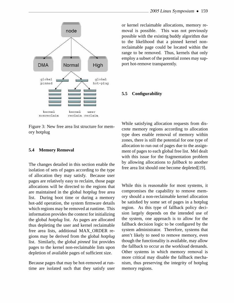
2005 Linux Symposium • 159
Figure 3: New free area list structure for mem-ory hotplug
5.4 Memory Removal
The changes detailed in this section enable theisolation of sets of pages according to the typeof allocation they may satisfy. Because userpages are relatively easy to reclaim, those pageallocations will be directed to the regions thatare maintained in the globalhotplug free arealist. During boot time or during a memoryhot-add operation, the system firmware detailswhich regions may be removed at runtime. Thisinformation provides the context for initializingthe globalhotplug list. As pages are allocatedthus depleting the user and kernel reclaimablefree area lists, additional MAX_ORDER re-gions may be derived from the globalhotpluglist. Similarly, the globalpinned list providespages to the kernel non-reclaimable lists upondepletion of available pages of sufficient size.
Because pages that may be hot-removed at run-time are isolated such that they satisfy user
or kernel reclaimable allocations, memory re-moval is possible. This was not previouslypossible with the existing buddy algorithm dueto the likelihood that a pinned kernel non-reclaimable page could be located within therange to be removed. Thus, kernels that onlyemploy a subset of the potential zones may sup-port hot-remove transparently.
5.5 Configurability
While satisfying allocation requests from dis-crete memory regions according to allocationtype does enable removal of memory withinzones, there is still the potential for one type ofallocation to run out of pages due to the assign-ment of pages to each global free list. Mel dealtwith this issue for the fragmentation problemby allowing allocations tofallback to anotherfree area list should one become depleted[19].
While this is reasonable for most systems, itcompromises the capability to remove mem-ory should a non-reclaimable kernel allocationbe satisfied by some set of pages in a hotplugregion. As this type of fallback policy deci-sion largely depends on the intended use ofthe system, one approach is to allow for thefallback decision logic to be configured by thesystem administrator. Therefore, systems thataren’t likely to need to remove memory, eventhough the functionality is available, may allowthe fallback to occur as the workload demands.Other systems in which memory removal ismore critical may disable the fallback mecha-nism, thus preserving the integrity of hotplugmemory regions.

160 • Hotplug Memory Redux
6 Memory migration
6.1 Overview
In memory hotplug removal events, all thepages in some memory region must be freed ina timely fashion, while processes are runningas usual. Memory migration achieves this byblocking page accesses and moves page con-tents to new locations.
Although usingshrink_list() function—which is the core ofkswapd —sounds sim-pler, it cannot reliably free pages and causesmany disk I/Os. Additionally, the functioncannot handle pages which aren’t associatedwith any backing stores. Pages on a ramdiskare an example of this. The memory migra-tion is designed to solve these issues. Pageaccesses aren’t a problem because they areblocked, whileshrink_list() cannot pro-cess pages that are being accessed. Unlikeshrink_list() , most dirty pages can beprocessed without writing them back to disk.
6.2 Interface to Migrate Page
To migrate pages, create a list of pages tomigrate and call the following function:int try_to_migrate_pages(struct
list_head *page_list)
It returns zero on success, otherwise setspage_list to a list of pages that cannot migrateand returns a non-zero value. Callers mustcheck return values and retry failed pages ifnecessary.
This function is primarily for memory hotplugremove, but also can be used for memory de-fragmentation (see Section 8.1) or process mi-gration (see Section 8.2.3).
6.3 How does the memory migrationwork?
A memory migration operation consists of thefollowing steps. The operation of anonymouspages is slightly different.
1. lockoldpage , which is the target page
2. allocate and locknewpage
3. modify oldpage entry in page_
mapping(oldpage)->page_tree
with newpage
4. invoke try_to_unmap(oldpage,
virtual_address_list) to unmapoldpage from the process addressspaces.
5. wait until !PageWriteback(oldpage)
6. write backoldpage if oldpage is dirtyandPagePrivate(oldpage) and nofile system specific method is available
7. wait until page_count(oldpage)drops to 2
8. memcpy(newpage, oldpage,PAGE_SIZE)
9. makenewpage up to date
10. unlocknewpage to wakeup the waiters
11. freeoldpage
The key is to block accesses to the page un-der operation by modifying thepage_tree .After the page_tree has been modified, nonew access goes tooldpage . The accessesare redirected tonewpage and blocked untilthe data is ready because it is locked and isn’tup to date (Figure 4).

2005 Linux Symposium • 161
page_tree
address_space
oldpage
newpage
PG_uptodate
PG_lockedblocked
page faults
system calls
PTE
Figure 4: page_tree rewrite and page ac-cesses
To handle mlock() ed pages, try_to_unmap() now takes two arguments. If the sec-ond argument is non-NULL, the function un-mapsmlock()ed pages also and records un-mapped virtual addresses, which are used toreestablish the PTEs when the migration com-pletes.
Because the direct I/O code protects targetpages with incrementedpage_count , mem-ory migration doesn’t interfere with the I/O.
In some cases, a memory migration operationneeds to be rolled back and retried later. Thisis a bit tricky because it is likely that some pro-cesses have already looked up thepage_treeand are waiting for its lock. Such processesneed to discardnewpage and look up thepage_tree again, asnewpage is now in-valid.
6.3.1 Anonymous Memory Migration
The memory migration depends onpage_tree lists of inodes, while anony-mous pages may not correspond to any ofthem. This structure is strictly requiredto block all accesses to pages on it duringmigration.
Therefore, anonymous pages should be movedinto the swap-cache prior to migrating them.
After that these pages are placed in thepage_tree of swapper_space , whichmanages all pages in the swap-cache. Thesepages can be migrated just like pages in thepage-cache without any disk I/Os.
The important issue of systems without swapdevices remains. To solve it, Marcelo Tosattihas proposed the idea of “migration cache”[2]and he’s working on its implementation. Themigration cache is very similar to the swap-cache except it doesn’t require any swap de-vices.
6.4 Keeping Memory Management Awareof Memory Migration
The memory migration functionality is de-signed to fit the existing memory managementsemantics and most of the code works withouta modification. However, the memory manage-ment code should satisfy the following rules:
• Multiple lookups of a page from itspage_tree should be avoided. If a ker-nel function looks up apage_tree loca-tion multiple times, a memory migrationoperation can rewrite thepage_treein the meanwhile. When such apage_tree rewrite happens, it usuallyresults in a deadlock between the kernelfunction and the memory migration opera-tion. The memory migration implements atimeout mechanism to resolve such dead-locks, but it is preferable to remove thepossibility of deadlocks by avoiding mul-tiple page_tree lookups of the samepage. Another option is to use non-hotremovable memory for such pages.
• The pages which may be grabbed foran unpredictably long time must be al-located from non-hotremovable memory,

162 • Hotplug Memory Redux
even though it may be in the page-cache oranonymous memory. For instance, pagesused as ring buffers for asynchronous in-put/output (AIO) events are pinned not tobe freed.
• For a swap-cache page, its PG_swapcacheflag bit needs checking after obtaining thepage lock. This is due to how the mem-ory migration is implemented for swap-cache pages and not directly related to un-winding. Such a check code is added indo_swap_page() .
• Functions that calllock_page() mustbe aware of the unwinding of memorymigration. Basically, a page must bechecked if it is still valid after everylock_page() call. If it isn’t, one has torestart the operation from looking up thepage_tree again. A good example ofsuch restart is infind_lock_page() .
6.5 Tuning
6.5.1 Implementing File System SpecificMethods for Memory Migration
Memory migration works regardless of file sys-tems in use. However, it is desirable that filesystems which are intensively used implementthe helper functions which are described in thissubsection.
There are various things that refer to pages,and some of these references need time con-suming operations such as disk I/Os to com-plete in order for the reference to be dropped.This subsection focuses on one of these—thehandling of dirty buffer structures pointed bypage->private .
When a dirty page is associated with a buffer,the page must be made clean by issuing a write-
back operation and the buffer must be freed un-less there is an available file system specific op-eration defined.
The above operation can be too slow to be prac-tical because it has to wait a writeback I/Ocompletion. A file system specific operationcan be defined to avoid this problem by im-plementing themigrate_page() method inthe address_space_operations struc-ture.
For example, thebuffer_head structuresthat belong to ext2 file systems are handled bythemigrate_page_buffer function. Thisfunction enables page migration without write-back operations by havingnewpage to takeover thebuffer_head structure pointed bypage->private . It is implemented as fol-lows:
• Wait until the page_count dropsto the prescribed value (3 when thePG_private page flag is set, 2 oth-erwise). While waiting, issue thetry_to_unmap() function calls.
• If the PG_private flag is set, processthe buffer_head structure by callingthe generic_move_buffer() func-tion. The function waits until thebuffer_count drops and the bufferlock is released. Then, it hasnewpageto take over the buffer_head struc-ture by modifying page->private ,newpage->private and theb_pagemember in thebuffer_head struc-ture. To adjustpage_count due to thebuffer_head structure, increment thepage_count of newpage by one anddecrement the one ofpage by one.
• At this point, thepage_count of pageis 2 regardless of the original state of thePG_private flag.
2005 Linux Symposium • 163
6.5.2 Combination Withshrink_list()
Memory pressure caused by memory migra-tion can be reduced. This memory pressurecan cause reclaim of pages as replacements.Inactive pages are not worth migrating whenthe resultant migration causes other valid pagesbe reclaimed. This undesirable effect perturbsthe LRUness of pages reclaimed. It would bepreferable to just release these pages withoutmigrating them.
The current implementation[3] invokesshrink_list() to release inactive pagesand moves only active pages to new locationsin case of memory hotplug removal.
6.6 Hugetlb Page Migration.
Due to certain workloads like databases andhigh performance computing (HPC) large pagecapability is critical for good performance. Be-cause these pages are so critical to these work-loads it follows that page migration must sup-port migration of large pages to be widely used.
6.6.1 Interface to Migrate Hugetlb Pages
The prototype[5] interface for hugetlb migra-tion seperates normal page migration fromhuge page migration.
When a caller notices the page needing to bemigrated is a hugetlb page, it has to pass thepage totry_to_migrate_hugepage() ,migrating it without any system freeze or anyprocess suspension.
6.6.2 Design of hugetlb page migration
The migration can be done in the same way fornormal pages, using the same memory migra-
tion infrastructure. Luckily, it’s not so hardto implement because Linux kernel manageslarge pages—often called hugetlb pages—viathe pseudo file system known as hugetlbfs.
Linux kernel handles them in a similar manneras it handles normal pages in the page-cache.It inserts each of them into thepage_treeof the associated inode in hugetlbfs andmaps them into process address spaces usingmmap() system call.
There is one additional requirement for migra-tion of large pages. Demand paging againsthugetlb pages must be blocked, with all ac-cesses via process address spaces to pages un-der migration blocked in a pagefault handleruntil the migration is completed.
Therefore, the hugetlb page management re-lated to demand paging feature has to be en-hanced as follows:
• A pagefault handler for hugetlbpages must be implemented. Theimplementation[4] Chen, Kenneth W andChristoph Lameter are working on can beused with some modification, making theprocesses block in the pagefault handler ifthe page is locked. This is similar to whatthe pagefault handler for normal pagesdoes.
• The function try_to_unmap() mustbe able to handle hugetlb pages to un-map them from process address spaces.This meansobjrmap —the object-basedreverse mapping VM—also has to be in-troduced so that page table entries associ-ated with any pages can be found easily.
Another interesting topic is hugetlb page allo-cation, which is almost impossible to do dy-namically. Physically contiguous memory allo-

164 • Hotplug Memory Redux
target hugetlb page
migrate
page
page
migrate
migrate
memory defragmentation
page
Figure 5:hugetlb page migration
cation is one of the well known issues remain-ing to be solved. The current hugetlb page man-agement chooses the approach that all pagesshould be reserved at system start-up time.
Despite its current state, hugetlb page migra-tion can not continue to use this approach. Ondemand allocation is strictly required. Fortu-nately, this is going to be solved with “Memorydefragmentation” (see Section 8.1). MarceloTosatti is working on “Free area splitting withinzones” effort (see section 5).
6.6.3 How hugetlb Page MigrationWorks
There really isn’t much difference betweenhugetlb page migration and normal page migra-tion. The following is the algorithm flow forthis migration.
1. Allocate a new hugetlb page from the pageallocator also known as the buddy allo-cator. This may require memory defrag-mentation to make a sufficient contiguousrange (figure 5).
2. Lock the newly allocated page andkeep it non-uptodate, without thePG_uptodate flag on it.
3. Replace a target hugetlb page with the newpage onpage_tree of the correspond-ing inode in hugetlbfs.
4. Unmap the target page from the processaddress spaces, clearing all page table en-tries mapping it.
5. Wait until all references on the target pageare gone.
6. Copy from the target page to the new page.
7. Make the new page uptodate, setting thePG_uptodate flag on it.
8. Release the target page into the page allo-cator directly.
9. Unlock the new page to wake up all wait-ers.
6.7 Restriction
Under some rare situations, pages cannot mi-grate, and making those migrations functionalwould require too much code to be practical.
• NFS page-cache may have a non-responding NFS server. NFS I/O requestscannot complete if the server isn’tresponding. The pages with such out-standing NFS I/O requests cannot migrate.It is technically possible to handle thissituation by updating all the references toan oldpage with ones to a newpage, butthe code modification would be very largeand probably not maintainable.
• Page-cache of which the file is usedby sendfile() are also problematic.When a page-cache page is used bysendfile() , its page_count is keptraised until corresponding TCP packetsare ACKed. This becomes a problemwhen a connection peer doesn’t read datafrom the TCP connection.

2005 Linux Symposium • 165
• RDMA client/server memory use mayalso be an issue but further investigationis required.
6.8 Future Work
Currently, nonlinear mmaped pages2 cannotmigrate astry_to_unmap() doesn’t unmapsuch pages. This must be addressed.
All file systems should have their ownmigrate_page() method. This will helpperformance considerably as the filesystemscan make more intelligent decisions about theirown data.
Kernel memory should be migratable too. Afirst approach would be migrating page ta-ble pages which consume significant memory.This migration should be reasonably straight-forward.
7 Architecture ImplementationSpecifics
Memory hotplug has been implemented onmany different architectures. Each of these ar-chitectures have unique hardware and conse-quently do memory management in differentways. They each present unique challenges andsolutions that should be of interest to future im-plementators on the other architectures that cur-rently don’t support memory hotplug. Addi-tionally, those whose architectures are alreadycovered can better understand their own archi-tectures by comparing them side by side withothers.
2With remap_file_pages() system call, sev-eral pieces of a file can be mapped into one contiguousvirtual memory.
7.1 PPC64 Implementation
The PPC64 architecture is perhaps the mostmature with respect to the support of memoryhotplug. This is because there are other operat-ing systems that currently support memory hot-plug on this architecture.
7.1.1 Logical Partition Environment
Operating Systems running on PPC64 oper-ate in a Logical Partition (LPAR) of the ma-chine. These LPARs are managed by a under-lying level of firmware known as the hypervi-sor. The hypervisor manages access to the ac-tual underlying hardware resources. It is possi-ble to dynamically modify the resources asso-ciated with an LPAR. Such dynamically mod-ifiable LPARS are known as Dynamic LPARS(DLPARs)[29].
Memory is one of the resources that can bedynamically added to or removed from a DL-PAR on PPC64. In a PPC64 system, physicalmemory is divided into memory blocks that arethen assigned to LPARs. The hypervisor per-forms remapping of real physical addresses toaddresses that are given to the LPAR3 Thesememory blocks with remapped addresses ap-pear as physical memory to the Operating Sys-tems in the LPAR. When an OS is started onan LPAR, the LPAR will have a set of mem-ory blocks assigned to it. In addition, mem-ory blocks can be added or removed to theLPAR while the OS is active. The size of mem-ory blocks managed by the hypervisor is scaledbased on the total amount of physical mem-ory in the machine. The minimum size block
3To Linux the addresses given to it are consideredphysical addresses, but they are not in actuality physicaladdresses. This causes no end of confusion in developersconversations because developers get confused over whatis a virtual address, physical address, remapped address,etc.

166 • Hotplug Memory Redux
is 16MB4. As a result, the default SPARSE-MEM section size for PPC64 is a relativelysmall 16MB.
7.1.2 Add/Remove Operations
On PPC64, the most common case of mem-ory hotplug is not expected to be the actual ad-dition or removal of DIMMs. Rather, mem-ory blocks will be added to or removed froma DLPAR by the hypervisor. These add or re-move operations are initiated on the HardwareManagement Console (HMC). When memoryis added to an LPAR, the HMC will notify adaemon running in the OS of the desire to addmemory blocks. The daemon in turn makesa special system call that results in calls be-ing made to the hypervisor. The hypervisorthen makes additional memory blocks availableto the OS. As part of the special system callprocessing, the physical address5 of these newblocks is obtained. With the physical addressknown, scripts called via the daemon use thesysfs memory hotplug interface to create newmemory sections associated with the memoryblocks.
For memory remove operations, the HMC onceagain contacts the daemon running in the OS.The OS then executes a script that uses the sysfsinterfaces to offline a memory section. Once asection is offlined, a special system call is madethat results in calls to the hypervisor to isolatethe memory from the DLPAR.
4256MB is a more typical minimum block size. Onsome machines the user can actually change the mini-mum block size the machine will use
5This is not the real physical address, but theremapped address that Linux thinks is a real physical ad-dress
7.1.3 Single Zone and Defragmentation
PPC64 makes minimal use of memory zones.This is because DMA operations can be per-formed to any memory address. As a result,only a single DMA zone is created on PPC64and no HIGHMEM or NORMAL zones. Ofcourse, there may be multiple DMA zones (oneper node) on a NUMA architecture. Havinga single zone makes things simpler but it doesnothing to segregate memory allocations of dif-ferent types. For example, on architectures thatsupport HIGHMEM, allocations for user pagesmostly come from this zone. Having multiplezones provides a very basic level of segrega-tion of different allocation types. Since we haveno such luxury on PPC64, we must employother methods to segregate allocation types.The memory defragmentation work done byMel Gorman is a good starting point for thiseffort[19]. Mel’s work segregates memory al-locations on the natural MAX_ORDER PAGEsize blocks managed by the page allocator. Be-cause PPC64 has a relatively small default sec-tion size of 16 MB, it should be possible to ex-tend this concept in an effort to segregate allo-cations to segment size blocks.
7.1.4 PPC64 Hypervisor Functionality
The PPC64 hypervisor provides functionalityto aid in the removal of memory sections. TheH_MIGRATE_DMA call aids in the remappingof DMA mapped pages. This call will selec-tively suspend bus traffic while migrating thecontents of DMA mapped pages. It also mod-ifies the Translation Control Entries (TCEs)used for DMA accesses. Such functionalitywill allow for the removal ofdifficult memorysections on PPC64.
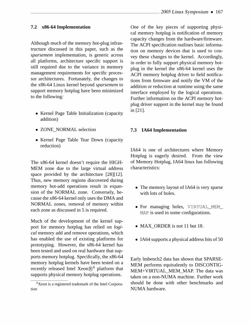
2005 Linux Symposium • 167
7.2 x86-64 Implementation
Although much of the memory hot-plug infras-tructure discussed in this paper, such as thesparsememimplementation, is generic acrossall platforms, architecture specific support isstill required due to the variance in memorymanagement requirements for specific proces-sor architectures. Fortunately, the changes tothe x86-64 Linux kernel beyondsparsememtosupport memory hotplug have been minimizedto the following:
• Kernel Page Table Initialization (capacityaddition)
• ZONE_NORMAL selection
• Kernel Page Table Tear Down (capacityreduction)
The x86-64 kernel doesn’t require the HIGH-MEM zone due to the large virtual addressspace provided by the architecture [28][12].Thus, new memory regions discovered duringmemory hot-add operations result in expan-sion of the NORMAL zone. Conversely, be-cause the x86-64 kernel only uses the DMA andNORMAL zones, removal of memory withineach zone as discussed in 5 is required.
Much of the development of the kernel sup-port for memory hotplug has relied onlogi-cal memory add and remove operations, whichhas enabled the use of existing platforms forprototyping. However, the x86-64 kernel hasbeen tested and used on real hardware that sup-ports memory hotplug. Specifically, the x86-64memory hotplug kernels have been tested on arecently released Intel XeonR©6 platform thatsupports physical memory hotplug operations.
6Xeon is a registered trademark of the Intel Corpora-tion
One of the key pieces of supporting physi-cal memory hotplug is notification of memorycapacity changes from the hardware/firmware.The ACPI specification outlines basic informa-tion on memory devices that is used to con-vey these changes to the kernel. Accordingly,in order to fully support physical memory hot-plug in the kernel the x86-64 kernel uses theACPI memory hotplug driver to field notifica-tions from firmware and notify the VM of theaddition or reduction at runtime using the sameinterface employed by the logical operations.Further information on the ACPI memory hot-plug driver support in the kernel may be foundin [21].
7.3 IA64 Implementation
IA64 is one of architectures where MemoryHotplug is eagerly desired. From the viewof Memory Hotplug, IA64 linux has followingcharacteristics:
• The memory layout of IA64 is very sparsewith lots of holes.
• For managing holes,VIRTUAL_MEM_MAPis used in some configurations.
• MAX_ORDER is not 11 but 18.
• IA64 supports a physical address bits of 50
Early lmbench2 data has shown that SPARSE-MEM performs equivalently to DISCONTIG-MEM+VIRTUAL_MEM_MAP. The data wastaken on a non-NUMA machine. Further workshould be done with other benchmarks andNUMA hardware.

168 • Hotplug Memory Redux
7.3.1 SPARSEMEM and VIRTUAL MEMMAP
The VM uses amemmap[], a linear ar-ray of page structures. With DISCONTIG-MEM, memmap[] is divided into severalnode_mem_maps. In general,memmap[] isallocated in physically contiguous pages at boottime.
The memory layout of IA64 is very sparsewith lots of holes. Sometimes there are GBsof memory holes, even for a non-NUMAmachine. In IA64 DISCONTIGMEM, avmemmapis used to avoid wasting memory. Avmemmapis amemmapwhich uses contiguousregion of virtual address instead of contiguousphysical memory.7
It is useful to hide holes and to create sparsememmap[]s. It resides in region 5 of the vir-tual address space, which uses virtual page ta-ble 8 like vmalloc.
Unfortunately, VIRTUAL_MEM_MAP isquite complicated. Because of the compli-cations VIRTUAL_MEM_MAP presents,early designs for MEMORY_HOTPLUGwere too complicated to be successfullyimplemented. SPARSEMEM cleanly re-moves VIRTUAL_MEM_MAP and thusavoids the associated complexity altogether.Because SPARSEMEM is simpler thanVIRTUAL_MEM_MAP it is a logical re-placement for VIRTUAL_MEM_MAP forsituations other than just hotplug. SPARSE-MEM divides the whole memmap intothe section’s section_memmap s. Allsection_memmap s reside in region 7 of thevirtual address space. Region 7 is an identitymapped segment and handled by the fast TLB
7VIRTUAL_MEM_MAP is configurable indepen-dent of DISCONTIGMEM
8VHPT, Virtual Hash Page Table, is a hardware sup-ported function to fill TLB
miss handler with big page size. If a holecovers the whole section, section_memmap isnot allocated. Holes in a section are treated asreserved pages. For example, an HP rx2600with 4GB of memory has the available physicalmemory at two locations with sizes of 1Gb and3Gb. For VIRTUAL_MEM_MAP the holeswould be represented by empty virtual spacewith vmemmap. SPARSEMEM handles a holewhich covers an entire section with an invalidsection.
7.3.2 SPARSEMEM NUMA
The mem_section[] array is on the BP’snode. Becausepfn_to_page() accesses it,a non BP nodepfn_to_page() is slightlymore expensive. Besides boot time the sectionarray is modified only during a hotplug event.These events should happen infrequently. Thisfrequently accessed but rarely changing datasuggests replicating the array into all nodes inorder to eliminate the non BP node penalty.Hotplug memory updates would have to notifyeach node of modifications to the array.
7.3.3 Size of Section and MAX_ORDER
One feature which is very aggresiveon IA64 is the configuration parameterFORCE_MAX_ZONEORDER. This over-writes MAX_ORDER to 18. For a 16kb pagesize the resultant MAX_ORDER region is4Gb(18+14). This is done for supporting4Gb HugetlbFS. SPARSEMEM constrainsPAGE_SIZE ∗ 2(MAX_ORDER−1) to be lessthan or equal to section size. For HugetlbFSwe have: (1)the smallest size of sectionis 4GB and (2)holes smaller than 4GBconsume reserved page structures. 18 ofMAX_ORDER seems to be rather optimistic

2005 Linux Symposium • 169
value for Memory Hotplug. Currently, con-figuation of FORCE_MAX_ZONEORDERis modified at compile time. At configu-ration time, if HUGETLB isn’t selected,FORCE_MAX_ZONEORDER can be con-figured to 11−20. If HUGETLB is selected,MAX_ORDER and SECTION_SIZE areadjusted to support 4Gb HUGETLB Page.
7.3.4 Vast 50 Bits Address Space of IA64
The IA64 architecture supports a physical ad-dress bit limit of 50, which can addresss up to1 petabyte of memory. A section array with a256Mb section size requires 32Mb of data tocover the whole address range. The Linux ker-nel by default is configured to only use 44 bitsmaximum, which can address 16 terabytes ofmemory. This only requires 512Kb of data tocover the whole address range. The number ofbits used is configurable at compile time.
8 Overlap with other efforts
During the development of memory hotplug thedevelopers discovered two surprising things.
• Parts of the memory hotplug code werevery useful to those who don’t care at allabout memory hotplug.
• Code others were developing without somuch as a thought of memory hotplugproved useful for memory hotplug.
This section attempts to briefly mention thesesurprising overlaps with other independent de-velopment without straying too far from thetopic of memory hotplug.
8.1 Memory Defragmentation
The primary concern for memory defragmen-tation within the VM subsystem is at the pagelevel. At the heart of this concern is the page al-locator and management of contiguous groupsof pages. Memory requests can be made forfor sizes in the range of a single page up to2(MAX_ORDER−1) contiguous pages. As timegoes by, various size allocations are obtainedand freed. The page allocator attempts to in-telligently group adjacent pages via the use ofbuddy allocator as previously described. How-ever, it still may become difficult to satisfy re-quests for large size allocations. When a suit-able size block is not found on the free lists,an attempt is made to reclaim pages so that asufficiently large block can assembled. Unfor-tunately, not all pages can be reclaimed. Forexample, those in use for kernel data. The freearea splitting concepts previously discussed ad-dress this issue. By grouping pages based onusage characteristics, the likelihood that a largeblock of pages can be reclaimed and ultimatelyallocated is greatly increased.
With memory hotplug, removing a memorysection is somewhat analogous to allocating allthe pages within the memory section. This isbecause all pages within the section must befree (not in use) before the section can be re-moved. Therefore, the concept of free list split-ting can also be applied to memory sectionsfor memory removal operations. Unfortunatelyhowever, memory sections do not map directlyto memory blocks managed by the page allo-cator. Rather, a memory section consists ofmultiple contiguous 2(MAX_ORDER−1) page sizeblocks. The number of blocks is dependenton architecture specific SECTION_SIZE andMAX_ORDER definitions. Future work withinthe memory hotplug project is to extend theconcepts used to avoid fragmentation to that ofmemory section size blocks. This will increase

170 • Hotplug Memory Redux
the likelihood that memory sections can be re-moved.
8.2 NUMA Memory Management
In a NUMA system, memory hotplug must con-sider the case where all of the memory on anode might be added/removed. Structures tomanage the node must be updated.
In addition, a user can specify nodes which areused by a user’s tasks by usingmbind() orset_mempolicy() in order to support loadbalancing among cpusets/dynamic partitioning.Memory hotplug has to not only update mem-policy information, but also make interfaces forload balancing scripts to move memory con-tents from nodes to other appropriate nodes.
8.2.1 Hotplug of Management Structuresfor a Node.
Structures which manage memory of a nodemust be updated in order to hotplug the nodeThis section describes some of the structures.
pgdat To reduce expensive cross node mem-ory accesses, Linux usespgdat struc-tures which include zone and zonelists.These structures are allocated on eachnode’s local memory in order to reduce ac-cess costs. If a new node is hotplug added,its pgdat structure should be allocated onits own node. Normally, there are no mmstructures for the node until the pgdat isinitialized, so pgdat has to be allocated byspecial routine early in the boot process.This allocation (getting a virtual addressand mapping physical address to it) is likea ioremap() , but it should be mappedon cached area unlikeioremap() .
zonelist The zonelist is an array of zone ad-dresses, and it is ordered by which zoneshould be used for its node. Its order isdetermined by access cost from a cpu tomemory and the zone’s attributes. Thisimplies when a node with memory is hot-plugged, all the node’s zonelists which arebeing accessed must be updated. For up-dating, the options are:
• getting locks
• giving up reordering
• stop other cpus while updating
Stopping other cpus while updating maybe the best way, because there is no im-pact on performance of page allocation un-less a hotplug event is in progress. In ad-dition, more structures than just zonelistsneed updating. For example, mempoli-cies of each process have to be updated toavoid using a removed node. To updatethem, the system has to remember all ofthe processes’ mempolicies. Linux doesnot currently do this, so further develop-ment is necessary.
8.2.2 Scattered Clone Structures AmongNodes
Pgdat, which includes zone and zonelist, isused to manage its own node, but some of datastructures’ clones are allocated on each of thenodes for light weight accesses. One currentexample isNODE_DATA() on IA64 imple-mentation. NODE_DATA(node_id) macropoints to eachnode_id ’s pgdat. In the IA64implementation,NODE_DATA(node_id) isnot just an array like it is in the IA32 imple-mentation. This data is localized on each nodeand it can be obtained fromper_cpu data.In this case, all of the nodes have clones ofpg_data_ptrs[] array.

2005 Linux Symposium • 171
#define local_node_data \local_cpu_data->node_data
#define NODE_DATA(nid) \local_node_data->pg_data_ptrs[nid]
Besides NODE_DATA(), many other datastructures which are often accessed are local-ized to each node. This implies that all ofthe node copies must also be updated whena hotplug event occurs. To update them,stop_machine_run may prove to be thebest method of serializing access.
8.2.3 Process Migration on NUMA
It is important to determine what the best des-tination node is for migration of memory con-tents. This applies not only automatic migra-tion, but also “manual page migration” as pro-posed by Ray Bryant at SGI. With manual pagemigration a load balancer script can specify thedestination node for migrating existing mem-ory. A potential interface would be a simplesystem call likesys_migrate_pages(pid,
oldnode, newnode) .
However, if there are too many nodes (ex, 128nodes) and tasks (ex, 256 processes) in the sys-tem, this system call will be called too fre-quently. Therefore, Ray Bryant is proposingan array interface to specify each node to avoidtoo many calls:sys_migrate_pages(pid,
count, old_nodes, new_nodes) .
The arguments tosys_migrate_pages()old_nodes andnew_nodes are the sets ofsource and destination nodes and count is thenumber of elements in each array. Therefore, auser can just callsys_migrate_pages()once for each task. If each task uses sharedmessage blocks, there will be a large reductionin the number of system calls.
9 Conclusion
Hotplug Memory is real and achievable due tothe dedication of its developers. This paperhas shown that the issues with memory hotplughave been well thought out. Most of memoryhotplug has already been implemented and ismaintained in the-mhp tree[3]—broken downinto the smallest possible independent piecesfor continued development. These small piecesare released early and often. As individualpieces of this code become ready for consump-tion by the general public they are merged up-stream. By maintaining this separate tree whichis updated at least once per -rc release, hotplugdevelopers have been able to test and stabilizean increasing amount of memory hotplug code.Thus, the pieces that get merged upstream aresmall, non-disruptive, and well tested.
Memory hotplug is a model of how a large, dis-ruptive feature can be developed and mergedinto a continuously stable kernel. In fact, hav-ing a stable kernel has made development muchmore disciplined, debugging easier, conflictswith other developers easier to identify, feed-back more thorough, and generally has been ablessing in disguise.
If in a parallel universe somewhere AndrewMorton gave his keynote today instead of ayear ago I suspect he would say something dif-ferent. The parallel universe Andrew Mortonmight say:
“Some features tend to be pervasive and havetheir little sticky fingers into lots of differentplaces in the code base. An example of whichcomes to mind is CPU hot plug, and memoryhot unplug. We may not be able to accept thesefeatures into a 2.7 development kernel due totheir long-term impact on stabilizing that ker-nel. To make it easier on the developers of fea-tures like these we have decided to never have a

172 • Hotplug Memory Redux
2.7 development kernel. Because of this, I ex-pect CPU hot plug and memory hot unplug tobe merged with relative ease as they reach thelevel of stability of the rest of the kernel.”
10 Acknowledgments
Special thanks to Ray Bryant of SGI for his re-view on NUMA migration, New Energy andIndustrial Technology Development Organiza-tion for funding some of the contributions fromthe authors who work at Fujitsu, Martin Blighfor his NUMA work and his work on IBMs testenvironment, Andy Whitcroft for his work onSPARSEMEM, Andrew Morton and the quiltdevelopers for giving us something to manageall of these patches, Sourceforge for hosting ourmailing list, OSDL for the work of the Hot-plug SIG—especially their work on testing, andMartine Silbermann for valuable feedback.
11 Legal Statement
This work represents the view of the authors anddoes not necessarily represent the view of IBM, In-tel, Fujitsu, or HP.
IBM is a trademark or registered trademark of In-ternational Business Machines Corporation in theUnited Sates and/or other countries.
Intel is a trademark or registered trademark of IntelCorporation in the United States, other countries, orboth.
Fujitsu is a trademark or registered trademark of Fu-jitsu Limited in Japan and/or other countries.
Linux is a registered trademark of Linus Torvalds.
References
[1] http://www.groklaw.net/article.php?story=20040802115731932
[2] M. Tosatti ([email protected] ) (14 Oct 2004),Patch:Migration Cache. Email to Dave Hansen,Iwamoto Toshihiro, Hiroyuki Kamezawa,[email protected] (http://lwn.net/Articles/106977/ )
[3] http://sr71.net/patches/
[4] C. Lameter ([email protected]) (21 Oct2004)Patch: Hugepages demand pagingV1[0/4]: Discussion and Overview.Email to Kenneth Chen, William LeeIrwin III, Ray Bryant,[email protected] (http://lwn.net/Articles/107719/ )
[5] H. Takahashi, 2004 [online]. Linuxmemory hotplug for Hugepages.Available from:http://people.valinux.co.jp/~taka/hpageremap.html[Accessed 2004].
[6] D. Hansen, M. Kravetz, B. Christiansen,M. Tolentino. Hotplug Memory and theLinux VM. In Proceedings of the OttawaLinux Symposium,Ottawa, Ontario,Canada, pages 278–294, July 2004.
[7] K. Knowlton. A Fast Storage Allocator.In Communications of the ACM,Vol. 8,Issue 10, pages 623–624, October 1965.
[8] M. Gorman. Understanding the LinuxVirtual Memory Manager, Prentice Hall,NJ, 2004.
[9] W. Bolosky, R. Fitzgerald, M. Scott.Simple But Effective Techniques for

2005 Linux Symposium • 173
NUMA Memory Management. InProceedings of the 12th ACM Symposiumon Operating Systems Principles,pages19–31, 1989.
[10] P. Barham, B. Dragovic, K. Fraser, S.Hand, T. Harris, A. Ho, R. Neugebauer, I.Pratt, A. Warfield. Xen and the Art ofVirtualization. InProceedings of theNineteenth ACM Symposium onOperating System Principles,pages164–177, October 2003.
[11] E. Demaine, J. Munro. Fast Allocationand Deallocation with an ImprovedBuddy System. InProceedings of the19th Conference on Foundations ofSoftware Technology and TheoreticalComputer Science,pages 84–96, 1999.
[12] Intel Corporation. 64-Bit ExtensionTechnology Software Developer’s Guide.2004.
[13] K. Li and K. Peterson. Evaluation ofMemory System Extensions. InProceedings of 18th Annual InternationalSymposium on Computer Architecture,pages 84–93, 1991.
[14] D. Mosberger, S. Eranian. ia-64 LinuxKernel Design and Implementation.Prentice Hall, NJ, 2002.
[15] Z. Mwaikambo, A. Raj, R. Russell, J.Schopp, S. Vaddagiri. Linux KernelHotpug CPU Support. InProceedings ofthe Ottawa Linux Symposium,pages467–479, July 2004.
[16] J. Peterson, T. Norman. Buddy Systems.In Communications of the ACM,Vol. 20,Issue 6, pages 421–431, June 1977.
[17] C. Waldspurger. Memory ResourceManagement in VMware ESX Server. InProcedings of the 5th Symposium on
Operating System Design andImplementation,pages 181–194, 2002.
[18] M.S. Johnstone, P.R. Wilson. TheMemory Fragmentation Problem:Solved? InInternational Symposium onMemory Management,pages 26–36,Vancouver, British Columbia, Canada,1998.
[19] Linux Weekly News, 2005 [online]. Yetanother approach to memoryfragmentation. Available fromhttp://lwn.net/121618/[Accessed Feb. 2005]
[20] ACPI Specification Version 3.0http://www.acpi.info/spec.htm
[21] L. Brown,et al. The State of ACPI in theLinux Kernel. InProceedings of theOttawa Linux Symposium, Ottawa,Ontario, Canada, July 2005.
[22] B. Jacob, T. Mudge. Virtual Memory inContemporary Microprocessors, IEEEMicro, pages 60–75, July 1998
[23] R. Rashid, A. Tevanian, M. Young, D.Golub, R. Baron, D. Black, W. Bolosky,J. Chew. Machine Independent VirtualMemory Management for PagedUniprocessor and MultiprocessorArchitectures, InProceedings of SecondInternational Conference onArchitectural Support for ProgrammingLanguages and Operating Systems,pages31–39, 1987.
[24] S. Hand. Self-Paging in the NemesisOperating System, InProceedings of theThird Symposium on Operating SystemsDesign and Implementation,pages73–86, February 1999.
[25] P. Denning. Virtual Memory, InACMComputing Surveys (CSUR),Vol. 2, Issue3, pages 153–189, September 1970.

174 • Hotplug Memory Redux
[26] A. Bensoussan, C. Clingen, R. Daley.The Multics Virtual Memory, InCommunications of the ACM,Vol. 15,Issue 5, pages 308–318, May 1972.
[27] V. Abrossimov, M. Rozier. GenericVirtual Memory Management forOperating System Kernels. InProceedings of the 12th ACM Symposiumon Operating System Principles,pages123–136, November 1989.
[28] A. Kleen. Porting Linux to x86-64. InProceedings of the Ottawa LinuxSymposium,, Ottawa, Ontario, Canada,July 2001.
[29] IBM. Dynamic Logical Partitioning inIBM eserver pSeries. October 2002.
[30] D.H. Brown Associates, Inc. Capacity onDemand A Requirement for thee-Business Environment. IBM WhitePaper. September 2003.
[31] L.D. Paulson. Computer System, HealThyself. InIEEE Computer,Vol. 35,Issue 8, August 2002.

Enhancements to Linux I/O Scheduling
Seetharami Seelam, Rodrigo Romero, Patricia TellerUniversity of Texas at El Paso
{seelam, romero, pteller}@cs.utep.edu
Bill BurosIBM Linux Technology Center
Abstract
The Linux 2.6 release provides four disk I/Oschedulers: deadline, anticipatory, noop, andcompletely fair queuing (CFQ), along with anoption to select one of these four at boot timeor runtime. The selection is based ona pri-ori knowledge of the workload, file system,and I/O system hardware configuration, amongother factors. The anticipatory scheduler (AS)is the default. Although the AS performswell under many situations, we have identi-fied cases, under certain combinations of work-loads, where the AS leads to process starvation.To mitigate this problem, we implemented anextension to the AS (called Cooperative AS orCAS) and compared its performance with theother four schedulers. This paper briefly de-scribes the AS and the related deadline sched-uler, highlighting their shortcomings; in addi-tion, it gives a detailed description of the CAS.We report performance of all five schedulerson a set of workloads, which represent a widerange of I/O behavior. The study shows that(1) the CAS has an order of magnitude im-provement in performance in cases where theAS leads to process starvation and (2) in sev-eral cases the CAS has performance compa-rable to that of the other schedulers. But, as
the literature and this study reports, no onescheduler can provide the best possible perfor-mance for all workloads; accordingly, Linuxprovides four I/O schedulers from which to se-lect. Even when dealing with just four, in sys-tems that service concurrent workloads withdifferent I/O behaviors,a priori selection ofthe scheduler with the best possible perfor-mance can be an intricate task. Dynamic se-lection based on workload needs, system con-figuration, and other parameters can addressthis challenge. Accordingly, we are developingmetrics and heuristics that can be used for thispurpose. The paper concludes with a descrip-tion of our efforts in this direction, in particular,we present a characterization function, basedon metrics related to system behavior and I/Orequests, that can be used to measure and com-pare scheduling algorithm performance. Thischaracterization function can be used to dy-namically select an appropriate scheduler basedon observed system behavior.
1 Introduction
The Linux 2.6 release provides four disk I/Oschedulers: deadline, anticipatory, completelyfair queuing (CFQ), and noop, along with an
• 175 •

176 • Enhancements to Linux I/O Scheduling
option to select one of these at boot time or run-time. Selection is based ona priori knowledgeof the workload, file system, and I/O systemhardware configuration, among other factors.In the absence of a selection at boot time, theanticipatory scheduler (AS) is the default sinceit has been shown to perform better than theothers under several circumstances [8, 9, 11].
To the best of our knowledge, there are noperformance studies of these I/O schedulersunder workloads comprised of concurrent I/Orequests generated by different processes thatexhibit different types of access patterns andmethods. We call these types of workloads“mixed workloads.” Such studies are of in-terest since, in contemporary multiprogram-ming/multiprocessor environments, it is quitenatural to have several different types of I/Orequests concurrently exercising the disk I/Osubsystem. In such situations, it is expectedthat the I/O scheduler will not deprive any pro-cess of its required I/O resources even whenthe scheduler’s performance goals are met bythe processing of concurrent requests gener-ated by other processes. In contrast, due to theanticipatory nature of the AS, there are situa-tions, which we identify in this paper, whenthe AS leads to process starvation; these situ-ations occur when a mixed workload stressesthe disk I/O subsystem. Accordingly, this pa-per answers the following three questions andaddresses a fourth one, which is posed in thenext paragraph.
Q1. Are there mixed workloads that potentiallycan starve under the AS due to its anticipatorynature?
Q2. Can the AS be extended to prevent suchstarvation?
Q3. What is the impact of the extended sched-uler on the execution time of some realisticbenchmarks?
In this paper we also explore the idea of dy-namic scheduler selection. In an effort to de-termine the best scheduler, [13] quantifies theperformance of the four I/O schedulers for dif-ferent workloads, file systems, and hardwareconfigurations. The conclusion of the study isthat there is “no silver bullet,” i.e., none of theschedulers consistently provide the best possi-ble performance under different workload, soft-ware, and hardware combinations. The studyshows that (1) for the selected workloads andsystems, the AS provides the best performancefor sequential read requests executed on sin-gle disk hardware configurations; (2) for mod-erate hardware configurations (RAID systemswith 2-5 disks), the deadline and CFQ sched-ulers perform better than the others; (3) thenoop scheduler is particularly suitable for largeRAID (e.g., RAID-0 with tens of disks) sys-tems consisting of SCSI drives that have theirown scheduling and caching mechanisms; and(4) the AS and deadline scheduler provide sub-stantially good performance in single disk and2-5 disk configurations; sometimes the AS per-forms better than the deadline scheduler andvice versa. The study infers that to get thebest possible performance, scheduler selectionshould be dynamic. So, the final question weaddress in this paper is:
Q4. Can metrics be used to guide dynamic se-lection of I/O schedulers?
The paper is organized as follows. Section 2describes the deadline and anticipatory sched-ulers, highlighting similarities and differences.The first and second questions are answered inSections 3 and 4, respectively, by demonstrat-ing that processes can potentially starve underthe AS and presenting an algorithm that ex-tends the AS to prevent process starvation. Toanswer the third question, Section 5 presentsa comparative analysis of the deadline sched-uler, AS, and extended AS for a set of mixedworkloads. Furthermore, the execution times

2005 Linux Symposium • 177
of a set of benchmarks that simulate web, file,and mail servers, and metadata are executed un-der all five schedulers are compared. Finally,the fourth question is addressed in Section 6,which presents microbenchmark-based heuris-tics and metrics for I/O request characterizationthat can be used to guide dynamic scheduler se-lection. Sections 7, 8, and 9 conclude the paperby highlighting our future work, describing re-lated work, and presenting conclusions, respec-tively.
2 Description of I/O Schedulers
This section describes two of the four sched-ulers provided by Linux 2.6, the deadlinescheduler and the anticipatory scheduler (AS).The deadline scheduler is described first be-cause the AS is built upon it. Similaritiesand differences between the two schedulers arehighlighted. For a description of the CFQ andnoop schedulers, refer to [13].
2.1 Deadline Scheduler
The deadline scheduler maintains two separatelists, one for read requests and one for writerequests, which are ordered by logical blocknumber—these are called thesort lists. Duringthe enqueue phase, an incoming request is as-signed an expiration time, also calleddeadline,and is inserted into one of the sort lists and oneof two additional queues (one for reads and onefor writes) ordered by expiration time—theseare called thefifo lists. Scheduling a request toa disk drive involves inserting it into a dispatchlist, which is ordered by block number, anddeleting it from two lists, for example, the readfifo and read sort lists. Usually a set of contigu-ous requests is moved to the dispatch list. Arequest that requires a disk seek is counted as
16 contiguous requests. Requests are selectedby the scheduler using the algorithm presentedbelow.
Step 1: If there are write requests in the writesort list and the last two scheduled requestswere selected using step 2 and/or step 3, thenselect a set of write requests from the write sortlist and exit.
Step 2: If there are read requests with expireddeadlines in the read fifo list, then select a setof read requests from this list and exit.
Step 3: If there are read requests in the read sortlist, then select a set of read requests from thislist and exit.
Step 4: If there are write requests in the writesort list, then select a set of write requests fromthis list and exit.
When the scheduler assigns deadlines, it givesa higher preference to reads; a read is satisfiedwithin a specified period of time—500ms is thedefault—while a write has no strict deadline. Inorder to prevent write request starvation, whichis possible under this policy, writes are sched-uled after a certain number of reads.
The deadline scheduler is work-conserving—it schedules a request as soon as the previousrequest is serviced. This can lead to poten-tial problems. For example, in many applica-tions read requests aresynchronous, i.e., suc-cessive read requests are separated by smallchunks of computation, and, thus, successiveread requests from a process are separated bya small delay. Ifp (p > 1) processes of thistype are executing concurrently, then ifp re-quests, one from each process, arrive duringa time interval, a work-conserving schedulermay first select a request from one process andthen select a request from a different process.Consequently, the work-conserving nature ofthe deadline scheduler may result in deceptive

178 • Enhancements to Linux I/O Scheduling
idleness [7], a condition in which the sched-uler alternately selects requests from multipleprocesses that are accessing disjoint areas ofthe disk, resulting in a disk seek for each re-quest. Such deceptive idleness can be elimi-nated by introducing into the scheduler a shortdelay before I/O request selection; during thistime the scheduler waits for additional requestsfrom the process that issued the previous re-quest. Such schedulers are called non-work-conserving schedulers because they trade offdisk utilization for throughput. The anticipa-tory scheduler, described next in Section 2.2,is an example of such a scheduler. The de-ceptive idleness problem, with respect to thedeadline scheduler, is illustrated in Section 5,which presents experimental results for variousmicrobenchmarks and real workloads. A studyof the performance of the deadline schedulerunder a range of workloads also is presented inthe same section.
The Linux 2.6 deadline scheduler has severalparameters that can be tuned to obtain betterdisk I/O performance. Some of these param-eters are the deadline time for read requests(read_expire ), the number of requests tomove to the dispatch list (fifo_batch ),and the number of times the I/O sched-uler assigns preference to reads over writes(write_starved ). For a complete descrip-tion of the deadline scheduler and various tun-able parameters, refer to [13].
2.2 Anticipatory Scheduler
Theseek-reducing anticipatory scheduleris de-signed to minimize the number of seek op-erations in the presence of synchronous readrequests and eliminate the deceptive idlenessproblem [7]. Due to some licensing issues [14],the Linux 2.6 implementation of the AS, whichwe refer to asLAS, is somewhat different fromthe general idea described in [7]. Nonetheless,
the LAS follows the same basic idea, i.e., if thedisk just serviced a read request from processp then stall the disk and wait (some period oftime) for more requests from processp.
The LAS is comprised of three components:(1) the original, non-anticipatory disk sched-uler, which is essentially the deadline scheduleralgorithm with the deadlines associated with re-quests, (2) the anticipation core, and (3) the an-ticipation heuristic. The latter two serve readrequests. After scheduling a request for dis-patch, the deadline scheduler selects a pendingI/O request for dispatch. In contrast, the LAS,selects a pending I/O request, using the samecriteria as the deadline scheduler, and evaluatesit via its anticipation heuristic.
The anticipation core maintains statistics re-lated to all I/O requests and decaying frequencytables of exit probabilities, mean process seekdistances, and mean process think times. Theexit probabilityindicates the probability that ananticipated request, i.e., a request from thean-ticipated process, i.e., the process that gener-ated the last request, will not arrive. Accord-ingly, it is decremented when an anticipatedrequest arrives and is incremented otherwise,e.g., when a process terminates before generat-ing a subsequent I/O request. If the exit proba-bility exceeds a specified threshold, any requestthat arrives at the anticipation core is scheduledfor dispatch. The seek distance (think time) isthe difference between the logical block num-bers (arrival times) of two consecutive requests.These metrics—exit probability, mean processseek distance, and mean process seek time—are used by the anticipation heuristic, in combi-nation with current head position and requestedhead position, to determine anticipation time.
The anticipation heuristic evaluates whether tostall the disk for a specific period of time (waitperiod or anticipation time), in anticipation ofa “better request", for example from the an-ticipated process, or to schedule the selected

2005 Linux Symposium • 179
request for dispatch. The anticipation heuris-tic used in the LAS is based on the shortestpositioning time first (SPTF) scheduling pol-icy. Given the current head position, it evalu-aes which request, anticipated or selected, willpotentially result in the shortest seek distance.This evaluation is made by calculating the po-sitioning times for both requests. If the logicalblock of the selected request is close to the cur-rent head position, the heuristic returns zero,which causes the request to be scheduled fordispatch. Otherwise, the heuristic returns a pos-itive integer, i.e., the anticipation time, the timeto wait for an anticipated request. Since syn-chronous requests are initiated by a single pro-cess with interleaved computation, the processthat issued the last request may soon issue a re-quest for a nearby block.
During the anticipation time, which usually issmall (a few milliseconds—6ms is the default)and can be adjusted, the scheduler waits for theanticipated request. If a new request arrivesduring the wait period, it is evaluated immedi-ately with the anticipation heuristic. If it is theanticipated request, the scheduler inserts it intothe dispatch list. Otherwise, the following al-gorithm is executed. If the algorithm does notresult in the new request being scheduled fordispatch, the core continues to anticipate andthe disk is kept idle; this leads to potential prob-lems, some of which are described in Section 3.
Step 1: If anticipation has been turned off, e.g.,as a result of a read request exceeding its dead-line, then update process statistics, schedule thestarving request for dispatch, and exit.
Step 2: If the anticipation time has expired thenupdate process statistics, schedule the requestfor dispatch, and exit.
Step 3: If the anticipated process has termi-nated, update the exit probability, update pro-cess statistics, schedule the new request for dis-patch, and exit.
Step 4: If the request is a read request that willaccess a logical block that is “close” to the cur-rent head position, then update process statis-tics, schedule the new request for dispatch, andexit. In this case, there is no incentive to waitfor a “better” request.
Step 5: If the anticipated process just startedI/O and the exit probability is greater than 50%,update process statistics, schedule the new re-quest for dispatch, and exit; this process mayexit soon, thus, there is no added benefit in fur-ther anticipation. This step creates some prob-lems, further described in Section 3, when co-operative processes are executing concurrentlywith other processes.
Step 6: If the mean seek time of the anticipatedprocess is greater than the anticipation time, up-date process statistics, schedule the request fordispatch, and exit.
Step 7: If the mean seek distance of the an-ticipated process is greater than the seek dis-tance required to satisfy the new request, up-date process statistics, schedule the request fordispatch, and exit.
Unlike the deadline scheduler, the LAS allowslimited back seeks. A back seek occurs whenthe position of the head is in front of the headposition required to satisfy the selected request.In deadline and other work-conserving sched-ulers, such requests are placed at the end ofthe queue. There is some cost involved in backseeks, thus, the number of back seeks is limitedto MAXBACK(1024*1024) sectors; see [13]for more information.
As described, the essential differences betweenthe LAS and deadline scheduler are the antici-pation core and heuristics, and back seeks. Per-formance of the LAS under a range of work-loads is studied in Section 5, which highlightsits performance problems.

180 • Enhancements to Linux I/O Scheduling
3 Anticipatory Scheduler Problems
The anticipatory scheduler (LAS) algorithm isbased on two assumptions: (1) synchronousdisk requests are issued by individual processes[7] and, thus, anticipation occurs only with re-spect to the process that issued the last request;and (2) for anticipation to work properly, theanticipated process must be alive; if the an-ticipated process dies, there is no further an-ticipation for requests to nearby sectors. In-stead, any request that arrives at the scheduleris scheduled for dispatch, irrespective of the re-quested head position and the current head po-sition. These two assumptions hold true as longas synchronous requests are issued by individ-ual processes. However, when a group of pro-cesses collectively issue synchronous requests,the above assumptions are faulty and can resultin (1) faulty anticipation, but not necessarilybad disk throughput, and (2) a seek storm whenmultiple sets of short-lived groups of processes,which are created and terminated in a veryshort time interval, issue synchronous requestscollectively and simultaneously to disjoint setsof disk area, resulting in poor disk through-put. We call processes that collectively issuesynchronous requests to a nearby set of diskblocks cooperative processes. Examples ofprograms that generate cooperative processesinclude shell scripts that read the Linux sourcetree, different instances ofmake scripts thatcompile large programs and concurrently reada small set of source files, and different pro-grams or processes that read several databaserecords. We demonstrate related behavior andassociated performance problems using the twoexamples below.
3.1 Concurrent Streaming and ChunkRead Programs
First, we demonstrate how the first assump-tion of the LAS can lead to process starvation.
Consider two programs, A and B, presented inFigure 2. Program A generates a stream ofsynchronous read requests by a single process,while program B generates a sequence of de-pendent chunk read requests, each set of whichis generated by a different process.
Assume that Program B is reading the top-leveldirectory of the Linux source tree. The pro-gram reads all the files in the source tree, in-cluding those in the subdirectories, one file ata time, and does not read any file outside thetop-level directory. Note that each file is readby a different process, i.e., when Program B isexecuted, a group of processes is created, oneafter the other, and each issues synchronousdisk read requests. For this program, con-sider the performance effect of the first assump-tion, i.e., the per-process anticipation built intothe LAS. Recall that LAS anticipation worksonly on a per-process basis and provides im-proved performance only under multiple out-standing requests that will access disjoint setsof disk blocks. When Program A or B is ex-ecuted while no other processes are accessingthe disk, anticipation does not reap a benefitbecause there is only a small set of pending I/Orequests (due to prefetching) that are associatedwith the executing program. There are no diskhead seeks that are targets for performance im-provement.
Now consider executing both programs concur-rently. Assume that they access disjoint diskblocks and the size of thebig-file readby Program A is larger than that of the buffercache. In this case, each read request resultsin a true disk access rather than a read fromthe buffered file copy. Since the two programsare executing concurrently, at any point in timethere are at least two pending I/O requests, onegenerated by each of the processes. Program Bsequentially creates multiple processes that ac-cess the disk and only a small set of the totalnumber of I/O requests generated by Program

2005 Linux Symposium • 181
B corresponds to a single process; all read re-quests associated with a particular file are gen-erated by one process. In contrast, the execu-tion of Program A involves only one processthat generates all I/O requests. Since the antic-ipation built into the LAS is associated with aprocess, it fails to exploit the disk spatial local-ity of reference of read requests generated bythe execution of Program B; however, it workswell for the requests generated by Program A.More important is the fact that concurrent ex-ecution of these two programs results in star-vation of processes generated by Program B.Experimental evidence of this is presented inSection 5.
3.2 Concurrent Chunk Read Programs
This section demonstrates how the second as-sumption of the LAS can fail and, hence, leadto poor disk throughput. Consider the concur-rent execution of two instances of Program B,instances 1 and 2, reading the top-level direc-tory of two separate Linux source trees thatare stored in disjoint sets of disk blocks. As-sume that there areF files in each source tree.Accordingly, each instance of Program B cre-atesF different processes sequentially, each ofwhich reads a different file from the disk.
For this scenario, consider the performance ef-fect of the second assumption, i.e., once theanticipated process terminates, anticipation forrequests to nearby sectors ceases. When twoinstances of program B are executing concur-rently, at any point in time there are at leasttwo pending I/O requests, one generated byeach program instance. Recall that requeststo any one file correspond to only one pro-cess. In this case, the anticipation works wellas long as only processess associated with oneprogram instance, say instance 1, are readingfiles. When there are processess from the two
instances reading files then the second assump-tion does not allow the scheduler to exploitthe disk spatial locality of reference of readrequests generated by another process associ-ated with instance 1. For example, given pend-ing I/O requests generated by two processes,one associated with instance 1 and one asso-ciated with instance 2, anticipation will workwell for each process in isolation. However,once a process from one instance, say instance1, terminates, even if there are pending requestsfrom another process of instance 1, the sched-uler schedules for dispatch a request of the pro-cess of instance 2. This results in a disk seekand anticipation on the instance 2 process thatgenerated the request. This behavior iteratesfor the duration of the execution of the pro-grams. As a result, instead of servicing all readrequests corresponding to one source tree and,thus, minimizing disk seeks, an expensive se-quence of seeks, caused by alternating betweenprocesses of the two instances of Program B,occurs. For this scenario, at least 2F −1 seeksare necessary to service the requests generatedby both instances of Program B. As demon-strated, adherence to the second assumption ofthe LAS leads to seek storms that result in poordisk throughput. Experimental evidence of thisproblem is presented in Section 5.
4 Cooperative Anticipatory Sched-uler
In this section we present an extension to theLAS that addresses the faulty assumptions de-scribed in Section 3 and, thus, solves the prob-lems of potential process starvation and poordisk throughput. We call this scheduler theCooperative Anticipatory Scheduler (CAS). Toaddress potential problems, the notion of antic-ipation is broadened. When a request arrivesat the anticipation core during an anticipation
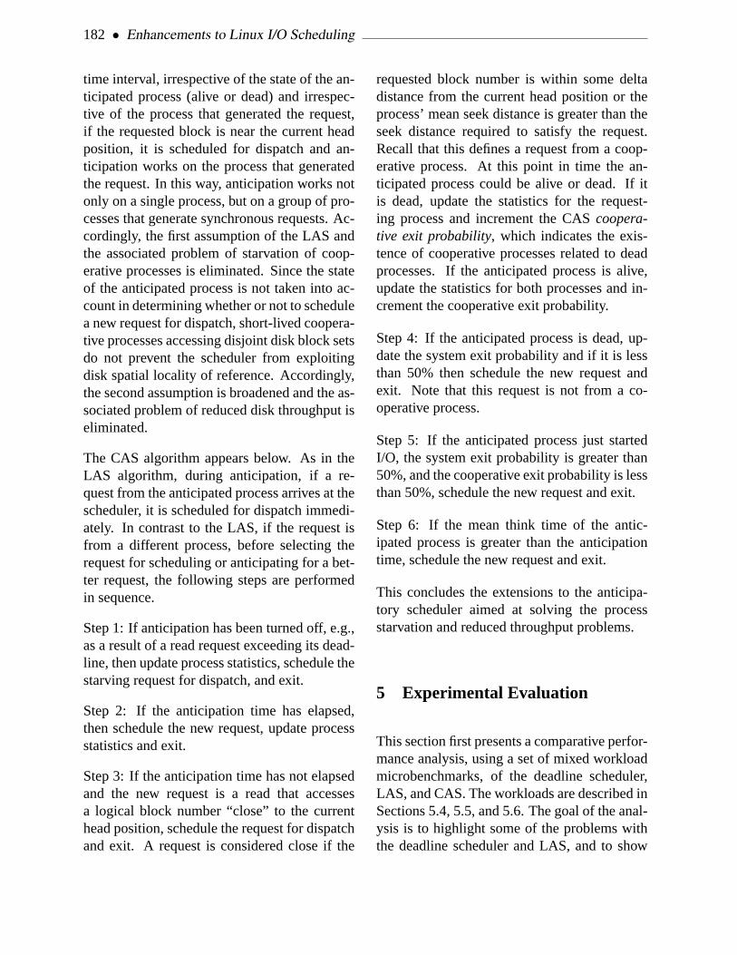
182 • Enhancements to Linux I/O Scheduling
time interval, irrespective of the state of the an-ticipated process (alive or dead) and irrespec-tive of the process that generated the request,if the requested block is near the current headposition, it is scheduled for dispatch and an-ticipation works on the process that generatedthe request. In this way, anticipation works notonly on a single process, but on a group of pro-cesses that generate synchronous requests. Ac-cordingly, the first assumption of the LAS andthe associated problem of starvation of coop-erative processes is eliminated. Since the stateof the anticipated process is not taken into ac-count in determining whether or not to schedulea new request for dispatch, short-lived coopera-tive processes accessing disjoint disk block setsdo not prevent the scheduler from exploitingdisk spatial locality of reference. Accordingly,the second assumption is broadened and the as-sociated problem of reduced disk throughput iseliminated.
The CAS algorithm appears below. As in theLAS algorithm, during anticipation, if a re-quest from the anticipated process arrives at thescheduler, it is scheduled for dispatch immedi-ately. In contrast to the LAS, if the request isfrom a different process, before selecting therequest for scheduling or anticipating for a bet-ter request, the following steps are performedin sequence.
Step 1: If anticipation has been turned off, e.g.,as a result of a read request exceeding its dead-line, then update process statistics, schedule thestarving request for dispatch, and exit.
Step 2: If the anticipation time has elapsed,then schedule the new request, update processstatistics and exit.
Step 3: If the anticipation time has not elapsedand the new request is a read that accessesa logical block number “close” to the currenthead position, schedule the request for dispatchand exit. A request is considered close if the
requested block number is within some deltadistance from the current head position or theprocess’ mean seek distance is greater than theseek distance required to satisfy the request.Recall that this defines a request from a coop-erative process. At this point in time the an-ticipated process could be alive or dead. If itis dead, update the statistics for the request-ing process and increment the CAScoopera-tive exit probability, which indicates the exis-tence of cooperative processes related to deadprocesses. If the anticipated process is alive,update the statistics for both processes and in-crement the cooperative exit probability.
Step 4: If the anticipated process is dead, up-date the system exit probability and if it is lessthan 50% then schedule the new request andexit. Note that this request is not from a co-operative process.
Step 5: If the anticipated process just startedI/O, the system exit probability is greater than50%, and the cooperative exit probability is lessthan 50%, schedule the new request and exit.
Step 6: If the mean think time of the antic-ipated process is greater than the anticipationtime, schedule the new request and exit.
This concludes the extensions to the anticipa-tory scheduler aimed at solving the processstarvation and reduced throughput problems.
5 Experimental Evaluation
This section first presents a comparative perfor-mance analysis, using a set of mixed workloadmicrobenchmarks, of the deadline scheduler,LAS, and CAS. The workloads are described inSections 5.4, 5.5, and 5.6. The goal of the anal-ysis is to highlight some of the problems withthe deadline scheduler and LAS, and to show

2005 Linux Symposium • 183
that the CAS indeed solves these problems.Second, we compare the execution times, underall five schedulers, of a set of benchmark pro-files that simulate web, file, and mail servers,and metadata. A general description of theseprofiles is provided in Section 5.1 and individ-ual workloads are described in Sections 5.7-5.10. The goal of this comparison is to showthat the CAS, in fact, performs better or as goodas the LAS under workloads with a wide rangeof characteristics. Using these benchmarks, weshow that (1) the LAS can lead to process star-vation and reduced disk throughput problemsthat can be mitigated by the CAS, and (2) un-der various workload scenarios, which are dif-ferent from those used to demonstrate processstarvation or reduced throughput, the CAS hasperformance comparable to the LAS.
5.1 Workload Description
The Flexible File System Benchmark (FFSB)infrastructure [6] is the workload generatorused to simulate web, file, and mail servers,and metadata. The workloads are specified us-ing profiles that are input to the FFSB infras-tructure, which simulates the required I/O be-havior. Initially, each profile is configured tocreate a total of 100,000 files in 100 directo-ries. Each file ranges in size from 4 KB to 64KB; the total size of the files exceeds the sizeof system memory so that the randomopera-tions (file read, write, append, create, or deleteactions) are performed from disk and not frommemory. File creation time is not counted inbenchmark execution time. A profile is config-ured to create four threads that randomly ex-ecute a total of 80,000 operations (20,000 perthread) on files stored in different directories.Each profile is executed three times under eachof the five schedulers on our experimental plat-form (described in Section 5.2). The average ofthe three execution times, as well as the stan-dard deviation, are reported for each scheduler.
5.2 Experimental Platform
We conducted the following experiments on adual-processor (2.28GHz Pentium 4 Xeon) sys-tem, with 1 GB main memory and 1 MB L2cache, running Linux 2.6.9. Only a single pro-cessor is used in this study. In order to elim-inate interference from operating system (OS)I/O requests, benchmark I/O accesses an ex-ternal 7,200 RPM Maxtor 20 GB IDE disk,which is different from the disk hosting theOS. The external drive is configured with theext3 file system and, for every experiment,is unmounted and re-mounted to remove buffercache effects.
5.3 Metrics
For the microbenchmark experiments, two ap-plication performance metrics, application ex-ecution time (in seconds) and aggregate diskthroughput (in MB/s), are used to demonstratethe problems with different schedulers. With noother processes executing in the system (exceptdaemons), I/O-intensive application executiontime is inversely proportional to disk through-put. In such situations, the scheduler with thesmallest application execution time is the bestscheduler for that workload. In mixed work-load scenarios, however, the execution time ofany one application cannot be used to compareschedulers. Due to the non-work-conservingnature of the LAS and CAS, these schedulers,when serving I/O requests, introduce delaysthat favor one application over another, some-times at the cost of increasing the executiontimes of other applications. Hence, in the pres-ence of other I/O-intensive processes, the ap-plication execution time metric must be cou-pled with other metrics to quantify the relativemerit of different schedulers. Consequently,we use the aggregate disk throughput metric insuch scenarios. Application execution time in-dicates the performance of a single application

184 • Enhancements to Linux I/O Scheduling
while truedo
Program 1:
done
Program 2:time cat 200mb-file > /dev/null
dd if=/dev/zero of=file \ count=2048 bs=1M
Figure 1: Program 1—generates stream writerequests; Program—2 generates stream read re-quests
and disk throughput indicates overall disk per-formance. Together, these two metrics help ex-pose potential process starvation and reducedthroughput problems with the LAS.
5.4 Experiment 1: Microbenchmarks—Streaming Writes and Reads
This experiment uses a mixed workload com-prised of two microbenchmarks [9], shown inFigure 1, to compare the performance of thedeadline scheduler, LAS, and CAS. It demon-strates the advantage of the LAS and CAS overthe deadline scheduler in a mixed workloadscenario. One microbenchmark, Program 1,generates a stream of write requests, while theother, Program 2, generates a stream of read re-quests. Note that the write requests generatedby Program 1 are asynchronous and can be de-layed to improve disk throughput. In contrast,Program 2 generates synchronous stream readrequests that must be serviced as fast as possi-ble.
When Programs 1 and 2 are executed concur-rently under the three different schedulers, ex-perimental results, i.e., application executiontimes and aggregate disk throughput, like those
shown in Table 1 are attained. These results in-dicate the following. (1) For synchronous readrequests, the LAS performs an order of mag-nitude better, in terms of execution time, andit provides 32% more disk throughput than thedeadline scheduler. (2) The CAS has perfor-mance similar to that of the LAS.
The LAS and CAS provide better performancethan the deadline scheduler by reducing un-necessary seeks and serving read requests asquickly as possible. For many such workloads,these schedulers improve request latency andaggregate disk throughput.
Scheduler Execution Time Throughput(sec.) (MB/s)
Deadline 129 25LAS 10 33CAS 9 33
Table 1: Performance of Programs 1 and 2 un-der the Deadline Scheduler, LAS, and CAS
5.5 Experiment 2: Microbenchmarks—Streaming and Chunk Reads
To compare the performance of the deadlinescheduler, LAS, and CAS, illustrate the processstarvation problem of the LAS, and show thatthe CAS solves this problem, this experimentuses a mixed workload microbenchmark com-prised of two microbenchmarks [9], shown inFigure 2. One microbenchmark, Program A,generates a stream of read requests, while theother, Program B, generates a sequence of de-pendent chunk read requests. Concurrent exe-cution of the two programs results in concur-rent generation of read requests from each pro-gram. Thus, assume that the read requests ofthese two programs are interleaved. In general,the servicing of a read request from one of theprograms will be followed by an expensive seek

2005 Linux Symposium • 185
Program A:while truedo cat big-file > /dev/nulldone
Program B:time find . -type f -exec \ cat ’{}’ ’;’ > /dev/null
Figure 2: Program—A generates stream readrequests; Program—B generates chunk read re-quests
in order to service a request from the other pro-gram; this situation repeats until one programterminates. However, if a moderate number ofrequests are anticipated correctly, the numberof expensive seeks is reduced. For each cor-rect anticipation, two seek operations are elim-inated; an incorrect anticipation costs a smalldelay. Accordingly, anticipation can be advan-tageous for a workload that generates depen-dent read requests, i.e., that exhibit disk spatiallocality of reference. However, as describedpreviously, the LAS can anticipate only if de-pendent read requests are from the same pro-cess. In this experiment the dependent read re-quests of Program A are from the same pro-cess, while the dependent chunk read requestsof Program B are from different processes.
Assume that Program B is reading the top-leveldirectory of the Linux source tree, as describedin Section 3.1. In this case, thefind commandfinds each file in the directory tree, then thecatcommand (spawned as a separate process) is-sues a read request to read the file, with thefile name provided by thefindprocess from thedisk. The newcat process reads the entire file,then the file is closed. This sequence of ac-tions is repeated until all files in the directoryare read.
Note that, in this case, each file read operationis performed by a different process, while LASanticipation works only on a per-process basis.Thus, if these processes are the only ones ac-cessing the disk, there will be no delays dueto seek operations to satisfy other processes.However, when run concurrently with ProgramA, the story is different, especially if, to elim-inate disk cache effects, we assume that thebig-file read by Program A is larger thanthe buffer cache. Note that during the execu-tion of Program A a single process generatesall read requests.
When these two programs are executed con-currently, anticipation works really well for thestreaming reads of Program A but it does notwork at all for the dependent chunk reads ofProgram B. The LAS is not able to recognizethe dependent disk spatial locality of referenceexhibited by thecat processes of Program B;this leads to starvation of these processes. Incontrast, the CAS identifies this locality of ref-erence and, thus, as shown in Table 2, providesbetter performance both in terms of executiontime and aggregate disk throughput. In addi-tion, it does not lead to process starvation.
Scheduler Execution ThroughputTime (sec.) (MB/s)
Deadline 297 9LAS 4767 35CAS 255 34
Table 2: Performance of Program A and B un-der the Deadline Scheduler, LAS, and CAS
The results in Table 2 show the following. (1)The LAS results in very bad execution time;this is likely because LAS anticipation doesnot work for Program B and, even worse, itworks really well for Program A, resulting ingood disk utilization for Program A and a verysmall amount of disk time being allocated forrequests from Program B. (2) The execution

186 • Enhancements to Linux I/O Scheduling
time under the deadline scheduler is 16 timessmaller than that under the LAS; this is likelybecause there is no anticipation in the deadlinescheduler. (3) Aggregate disk throughput un-der the deadline scheduler is 3.9 times smallerthan under the LAS; this is likely because LASanticipation works really well for Program A.(4) The CAS alleviates the anticipation prob-lems exhibited in the LAS for both dependentchunk reads (Program B) and dependent readworkloads (Program A). As a result, CAS pro-vides better execution time and aggregate diskthroughput.
5.6 Experiment 3: Microbenchmarks—Chunk Reads
To illustrate the reduced disk throughput prob-lem of the deadline scheduler and LAS and tofurther illustrate the performance of the CAS,this experiment first uses one instance of a mi-crobenchmark that generates a sequence of de-pendent chunk reads and then uses two con-currently executing instances of the same pro-gram, Program B of Figure 2, that access dis-joint Linux source trees. The results of this ex-periment are shown in Table 3 and Figure 3.
Scheduler Throughput (MB/s)1 Instance 2 Instances
Deadline 14.5 4.0LAS 15.5 4.0CAS 15.5 11.6
Table 3: Chunk Reads under the DeadlineScheduler, LAS, and CAS
As described before, in Program B a differ-ent cat process reads each of the files in thesource tree, thus, each execution of the programgenerates, in sequence, multiple processes thathave good disk spatial locality of reference.With two concurrently executing instances ofProgram B accessing disjoint sections of the
AS
Deadline
CAS
single
double
0
20
40
60
80
100
120
Execution time (seconds)
Figure 3: Reading the Linux Source: multi-ple, concurrent instances cause seek stormswith the deadline scheduler and LAS, which areeliminated by the CAS
disk, the deadline scheduler seeks back andforth several thousand times. The LAS is notable to identify the dependent read requestsgenerated by the differentcat processes and,thus, does not anticipate for them. As a re-sult, like the deadline scheduler, the LAS be-comes seek bound. In contrast, the CAS cap-tures the dependencies and, thus, provides bet-ter disk throughput and execution time. Recallthat, in this case, throughput is inversely pro-portional to execution time.
As shown in Figure 3 and Table 3, with one in-stance of Program B the three schedulers havea performance difference of about 7%. Onewould normally expect the execution time todouble for two instances of the program, how-ever, for the reasons described above the dead-line scheduler, LAS, and CAS increase their ex-ecution times by a factor of 7, 7, and 2.5, re-spectively. Again, the CAS has a smaller factorincrease (2.5) in execution time because it de-tects the dependencies among cooperative pro-cesses working in a localized area of disk and,thus, precludes the seek storms that occur oth-erwise in the deadline scheduler and LAS.

2005 Linux Symposium • 187
5.7 Experiment 4: Web Server Benchmark
This benchmark simulates the behavior of aweb server by making read requests to ran-domly selected files of different sizes. Themean of the three execution times for eachscheduler are reported in Figure 4 and Table 4.The numbers in the table are in seconds, andbold numbers indicate the scheduler with thebest execution time for each benchmark. It isworthwhile to point out that the standard de-viations of the results are less than 4% of theaverage values, which is small for all practi-cal purposes. From the table we can concludethat the CAS has the best performance of all theschedulers in the case of random reads and theCFQ has the worst performance. The LAS hasvery good execution time performance which iscomparable to that of CAS; it trails the CAS byless than 1%. The deadline, CFQ, and noopschedulers trail the CAS by 8%, 8.9%, and6.5%, respectively.
Scheduler Web Mail File MetaServer Server Server Data
Deadline 924 118 1127 305LAS 863 177 916 295CAS 855 109 890 288CFQ 931 112 1099 253noop 910 125 1127 319
Table 4: Mean Execution Times (seconds) ofDifferent Benchmark Programs
5.8 Experiment 5: File Server Benchmark
This benchmark simulates the behavior of atypical file server by making random read andwrite operations in the proportions of 80% and20%, respectively. The average of the three ex-ecution times are reported in Figure 4 and Ta-ble 4. The standard deviations of the results areless than 4.5% of the average values. Here we
CASAS
Deadline
CFQ
NOOP
Mail Server
MetaData
Web Server
File Server
0
200
400
600
800
1000
1200
Execution Time (seconds)
Figure 4: Mean Execution Time (seconds) onext3 File System
can conclude that the CAS has the best perfor-mance; the LAS trails the CAS by 2.9%; andthe other schedulers trail the CAS by at least23%.
5.9 Experiment 6: Mail Server Benchmark
This benchmark simulates the behavior of atypical mail server by executing random fileread, create, and delete operations in the pro-portions of 40%, 40%, and 20%, respectively.The average of the three execution times arereported in Figure 4 and Table 4. The stan-dard deviations of the results are less than 3.5%of the average values except for the LAS forwhich the standard deviation is about 11%.From these results we can conclude that theCAS has the best performance and the LAS hasthe worst performance, the LAS trails the CASby more than 62%. The CFQ scheduler hasvery good execution time performance com-pared to the CAS; it trails by a little more than3%. The deadline and noop schedulers trail theCAS by 8% and 14%, respectively.

188 • Enhancements to Linux I/O Scheduling
5.10 Experiment 7: MetaData Program
This benchmark simulates the behavior of atypical MetaData program by executing ran-dom file create, write-append, and delete opera-tions in the proportions of 40%, 40%, and 20%,respectively. Note that in this benchmark thereare no read requests. The average of the threeexecution times are reported in Figure 4 and Ta-ble 4. The standard deviations of the resultsare less than 3.5% of the average values exceptfor the noop scheduler for which the standarddeviation is 7.7%. From these results, we canconclude that the CFQ scheduler has the bestperformance. The LAS trails the CAS by 2%.The deadline, LAS, CAS, and noop schedulerstrail the CFQ, the best, scheduler by as much as26%.
6 I/O Scheduler Characterizationfor Scheduler Selection
Our experimentation (e.g., see Figure 4) aswell as the study in [13] reveals that no onescheduler can provide the best possible per-formance for different workload, software, andhardware combinations. A possible approachto this problem is to develop one scheduler thatcan best serve different types of these com-binations, however, this may not be possibledue to diverse workload requirements in realworld systems [13, 15]. This issue is furthercomplicated by the fact that workloads haveorthogonal requirements. For example, someworkloads, such as multimedia database appli-cations, prefer fairness over performance, oth-erwise streaming video applications may sufferfrom discontinuity in picture quality. In con-trast, server workloads, such as file servers, de-mand performance over fairness since small de-lays in serving individual requests are well tol-erated. In order to satisfy these conflicting re-
quirements, operating systems provide multi-ple I/O schedulers—each suitable for a differ-ent class of workloads—that can be selected, atboot time or runtime, based on workload char-acteristics.
The Linux 2.6.11 kernel provides four differentschedulers and an option to select one of themat boot time for the entire I/O system and switchbetween them at runtime on a per-disk basis [2].This selection is based ona priori understand-ing of workload characteristics, essentially by asystem administrator. Moreover, the schedulerselection varies based on the hardware config-uration of the disk (e.g., RAID setup), softwareconfiguration of the disk, i.e., file system, etc.Thus, static or dynamic scheduler selection isa daunting and intricate task. This is furthercomplicated by two other factors. (1) Systemsthat execute different kinds of workloads con-currently (e.g., a web server and a file server)—that require, individually, a different schedulerto obtain best possible performance—may notprovide best possible performance with a sin-gle scheduler selected at boot time or runtime.(2) Similarly, workloads with different phases,each phase with different I/O characteristics,will not be best served bya priori schedulerselection.
We propose a scheduler selection methodol-ogy that is based primarily on runtime work-load characteristics, in particular the averagerequest size. Ideally, dynamic scheduler selec-tion would be transparent to system hardwareand software. Moreover, a change in hard-ware or software configurations would be de-tected automatically and the scheduler selec-tion methodology would re-evaluate the sched-uler choice. With these goals in mind, we de-scribe below ideas towards the realization of arelated methodology.
We propose that runtime scheduler selectionbe based ona priori measurements of disk

2005 Linux Symposium • 189
Comparison of Different I/O Schedulers on RAID-0
0
9
18
27
36
45
1KB 4KB 16KB 32KB 65KB 256KB 1MB
Read Size
Bandwidth (MB/s) .
CFQ
AS
Deadline
NOOP
Points of interests
AS
Deadline
CFQ
Figure 5: Scheduler Ranking using a Mi-crobenchmark
throughput under the various schedulers and re-quest sizes. These measurements are then usedto generate a function that at runtime, given thecurrent average request size, returns the sched-uler that gives the best measured throughput forthe specified disk. Using the four schedulerson our experimental system, described in Sec-tion 5.2, augmented by a RAID-0 device withfour IDE 10 GB drives, we tooka priori mea-surements by executing a program that createsand randomly reads data blocks of various sizesfrom several large files. The system is config-ured with the ext3 file system; it runs the Linux2.6.11 kernel to permit switching schedulers.The ranking of the schedulers based on aver-age request size and disk throughput is shownin Figure 5. Experiments using this proposedmethodology to guide dynamic scheduler se-lection are in progress.
7 Future Work
Our cooperative anticipatory scheduler elim-inates the starvation problem of the AS byscheduling requests from other processes thataccess disk blocks close to the current headposition. It updates statistics related to re-quests on a per-process basis such that future-scheduling decisions can be made more appro-
priately. This scheduler has several tunable pa-rameters, e.g., the amount of time a requestspends in the queue before it is declared expiredand the amount of time the disk is kept idle inanticipation of future requests.
Because we were interested in investigating thepossible starvation problem and proposing asolution, we did not investigate the effects ofchanging these parameters; however, we havebegun to do so. We are especially interested instudying the performance effects of the CAS,with various parameter sets, on different disksystems. Given that the study shows that differ-ent parameter sets provide better performancefor systems with different disk sizes and config-urations [13], a methodology for dynamicallyselecting parameters is our goal. Furthermore,we intend to experiment with maintaining otherstatistics that can aid in making scheduling de-cisions for better disk performance. An exam-ple statistic is the number of times a processconsumes its anticipation time; if such a met-ric exceeds a certain threshold, it indicates thatthere is a mismatch between the workload ac-cess pattern and the scheduler and, hence, sucha process should not be a candidate for antici-pation.
With these types of advances, we will developa methodology for automatic and dynamic I/Oscheduler selection to meet application needsand to maximize disk throughput.
8 Related Work
To our knowledge the initial work on antici-patory scheduling, demonstrated on FreeBSDUnix, was done in [7]. Later, the general ideawas implemented in the Linux kernel by NickPiggin and was tested by Andrew Martin [11].To our surprise, during the time we were ex-ploring the I/O scheduler, the potential starva-

190 • Enhancements to Linux I/O Scheduling
tion problem was reported to the Linux com-munity independently on Linux mailing lists,however, no action was taken to fix the prob-lem [3].
Workload dependent performance of the fourI/O schedulers is presented in [13]; this workpoints out some performance problems withthe anticipatory scheduler in the Linux oper-ating system. There is work using genetic al-gorithms, i.e., natural evolution, selection, andmutation, to tune various I/O scheduler param-eters to fit workload needs [12]. In [15] the au-thors explore the idea of using seek time, av-erage waiting time in the queue, and the vari-ance in average waiting time in a utility func-tion that can be used to match schedulers toa wide range of workloads. This resulted inthe development of a maximum performancetwo-policy algorithm that essentially consistsof two schedulers, each suitable for differentranges of workloads. There also have beenattempts [2] to include in the CFQ schedulerpriorities and time slicing, analogous proces-sor scheduler concepts, along with the antic-ipatory statistics. This new scheduler, calledTime Sliced CFQ scheduler, incorporates the“good” ideas of other schedulers to provide thebest possible performance; however, as notedin posts to the Linux mailing list, this may notwork well in large RAID systems with TaggedCommand Queuing.
To the best of our knowledge, we are the firstto present a cooperative anticipatory schedulingalgorithm that extends traditional anticipatoryscheduling in such a way as to prevent processstarvation, mitigate disk throughput problemsdue to limited anticipation, and present a pre-liminary methodology to rank schedulers andprovide ideas to switch between them at run-time.
9 Conclusions
This paper identified a potential starvationproblem and a reduced disk throughput prob-lem in the anticipatory scheduler and proposeda cooperative anticipatory scheduling (CAS) al-gorithm that mitigates these problems. It alsodemonstrated that the CAS algorithm can pro-vide significant improvements in applicationexecution times as well as in disk throughput.At its core, the CAS algorithm extends the LASby broadening anticipation of I/O requests; itgives scheduling priority to requests not onlyfrom the process that generated the last requestbut also to processes that are part of a coop-erative process group. We implemented thismethodology in Linux.
In addition, the paper evaluated performancefor different workloads under the CAS and thefour schedulers in Linux 2.6. Microbench-marks were used to demonstrate the problemswith the Linux 2.6 schedulers and the effective-ness of the solution, i.e., the CAS. It was shownthat under the CAS web, mail, and file serverbenchmarks run as much as 62% faster.
Finally, the paper describes our efforts in rank-ing I/O schedulers based on system behavior aswell as workload request characteristics. Wehypothesize that these efforts will lead to amethodology that can be used to dynamicallyselect I/O schedulers and, thus improve perfor-mance.
10 Acknowledgements
We are grateful to Nick Piggin for taking thetime to answer a number of questions relatedto the implementation of the LAS and sharingsome of his thoughts. Also, we thank StevenPratt of IBM Linux Technology Center (LTC)

2005 Linux Symposium • 191
at IBM-Austin, TX for valuable discussions,Santhosh Rao of IBM LTC for his help withthe FFSB benchmark, and Jayaraman SureshBabu, UTEP, for his help with related experi-ments. This work is supported by the Depart-ment of Energy under Grant No. DE-FG02-04ER25622, an IBM SUR (Shared UniversityResearch) grant, and the University of Texas-El Paso.
11 Legal Statement
This work represents the view of the authors, anddoes not necessarily represent the view of the Uni-versity of Texas-El Paso or IBM. IBM is a trade-mark or registered trademark of International Busi-ness Machines Corporation in the United States,other countries, or both. Pentium is a trademark ofIntel Corporation in the United States, other coun-tries, or both. Other company, product, and servicenames may be trademarks or service marks of oth-ers. All the benchmarking was conducted for re-search purposes only, under laboratory conditions.Results will not be realized in all computing envi-ronments.
References
[1] Axboe, J., “Linux Block IO—Presentand Future,”Proceedings of the OttawaLinux Symposium 2004, Ottawa, Ontario,Canada, July 21–24, 2004, pp. 51–62
[2] Axobe, J., “Linux: Modular I/OSchedulers,”http://kerneltrap.org/node/3851
[3] Chatelle, J., “High Read Latency Test(Anticipatory I/O Scheduler),”http://linux.derkeiler.com/Mailing-Lists/Kernel/2004-02/5329.html
[4] Corbet, J., “Anticipatory I/OScheduling,”http://lwn.net/Articles/21274
[5] Godard, S., “SYSSTAT Utilities HomePage,”http://perso.wanadoo.fr/sebastien.godard/
[6] Heger, D., Jacobs, J., McCloskey, B., andStultz, J., “Evaluating SystemsPerformance in the Context ofPerformance Paths,”IBM TechnicalWhite Paper, IBM-Austin, TX, 2000
[7] Iyer, S., and Druschel, P., “AnticipatoryScheduling: a Disk SchedulingFramework to Overcome DeceptiveIdleness in Synchronous I/O,”18th ACMSymposium on Operating SystemsPrinciples (SOSP 2001), Banff, Alberta,Canada, October 2001, pp. 117–130
[8] Love, R.,Linux Kernel Development,Sams Publishing, 2004
[9] Love, R., “Kernel Korner: I/OSchedulers,”Linux Journal, February2004, 2004(118): p. 10
[10] Madhyastha, T., and Reed, D.,“Exploiting Global Input/Output AccessPattern Classification,”Proceedings ofSC ’97, San Jose, CA, November 1997,pp. 1–18
[11] Martin, A., “Linux: Where theAnticipatory Scheduler Shines,”http://www.kerneltrap.org/node.php?id=592
[12] Moilanen, J., “Genetic Algorithms in theKernel,” http://kerneltrap.org/node/4751
[13] Pratt, S., and Heger, D., “WorkloadDependent Performance Evaluation ofthe Linux 2.6 I/O Schedulers,”Proceedings of the Ottawa Linux

192 • Enhancements to Linux I/O Scheduling
Symposium 2004, Ottawa, Ontario,Canada, July 21–24, pp. 425–448
[14] Private communications with Nick Piggin
[15] Teory, T., and Pinkerton, T., “AComparative Analysis of DiskScheduling Policies,”Communications ofthe ACM, 1972, 15(3): pp. 177–184

Chip Multi Processing aware Linux Kernel Scheduler
Suresh [email protected]
Venkatesh [email protected]
Asit [email protected]
Abstract
Recent advances in semiconductor manufactur-ing and engineering technologies have led tothe inclusion of more than one CPU core in asingle physical processor package. This, pop-ularly know as Chip Multi Processing (CMP),allows multiple instruction streams to executeat the same time. CMP is in addition to today’sSimultaneous Multi Threading (SMT) capabil-ities, like IntelR© Hyper-Threading Technologywhich allows a processor to present itself as twological processors, resulting in best use of ex-ecution resources. With CMP, today’s LinuxKernel will deliver instantaneous performanceimprovement. In this paper, we will exploreideas for further improving peak performanceand power savings by making the Linux KernelScheduler CMP aware.
1 Introduction
To meet the growing requirements of proces-sor performance, processor architects are look-ing at new technologies and features focusingon enhanced performance at a lower power dis-sipation. One such technology is Simultane-ous Multi-Threading (SMT). Hyper-Threading(HT) Technology[5] introduced in 2002, is In-tel’s implementation of SMT. HT delivers two
logical processors running on the same execu-tion core, sharing all the resources like func-tional execution units and cache hierarchy. Thisapproach interleaves the execution of two in-struction streams, making the most effectiveuse of processor resources. It maximizes theperformance vs. transistor count and powerconsumption.
Recent advances in semiconductor manufactur-ing and engineering technologies are leading torapid increase in transistor count on a die. Forexample, forthcoming ItaniumR© family proces-sor code named Montecito will have more than1.7 billion transistors on a die! As the nextlogical step to SMT, these extra transistors areput to effective use by including more than oneexecution core with in a single physical pro-cessor package. This is popularly known asChip Multi Processing (CMP). Depending onthe number of execution cores in a package,it’s either called a dual-core[4] (two executioncores) or multi-core (more than two executioncores) capable processors. In multi-threadingand multi-tasking environment, CMP allowsfor significant improvement in performance atthe system level.
In this paper, in Section 2 we will look atan overview of CMP and some implementa-tion examples. Section 3 will talk about thegeneric OS scheduler optimization opportuni-ties that are appropriate in CMP environment.
• 193 •

194 • Chip Multi Processing aware Linux Kernel Scheduler
Linux Kernel Scheduler implementation detailsof these optimizations will be dwelled in Sec-tion 4. We will close the paper with a brief lookat CMP trends in future generation processors.
2 Chip Multi Processing
In a Chip Multi Processing capable physicalprocessor package, more than one executioncore reside in a physical package. Each corehas its own resources (architectural state, reg-isters, execution units, up-to a certain level ofcache, etc.). Shared resources between thecores in a physical package vary depending onthe implementation. Some of the implementa-tion examples are
a) each core could have a portion of on-diecache (for example L1) exclusively for itselfand then have a portion of on-die cache (forexample L2 and above) that is shared betweenthe cores. An example of this is the upcom-ing first mobile dual-core processor from Intel,code named Yonah.
b) each core having its own on-die cache hier-archy and its own communication path to theFront Side Bus (FSB). An example of this isthe IntelR© PentiumR© D processor.
Figure 1 shows a simplified block diagram ofa physical package which is CMP capable,where two execution cores reside in one physi-cal package, sharing the L2 cache and front sidebus resources.
A physical package can be both CMP and SMTcapable. In that case, each core in the physicalpackage can in turn contain more than one log-ical thread. For example, a dual-core with HTwill enable a single physical package to appearas four logical processors, capable of runningfour processes or threads simultaneously. Fig-ure 2 shows an example of a CMP with two
Figure 1: CMP implementation with two coressharing L2 cache and Bus interface
Figure 2: CMP implementation with two cores,each having two logical threads. Each core hastheir own cache hierarchy and communicationpath to FSB.
logical threads in each core and with each corehaving their own cache hierarchy and their owncommunication path to the FSB. An example ofthis is the IntelR© PentiumR© D Extreme Editionprocessor.
3 CMP Optimization opportunities
A multi-threaded application that scales welland is optimized on SMP systems will have aninstantaneous performance benefit from CMPbecause of these extra logical processors com-ing from cores and threads. Even if the appli-

2005 Linux Symposium • 195
cation is not multi-threaded, it can still take ad-vantage of these extra logical processors in amulti-tasking environment.
CMP also brings in new optimization oppor-tunities which will further improve the sys-tem performance. One of the optimization op-portunity is in the area of Operating System(OS) scheduler. Making the OS scheduler CMPaware will result in an improved peak perfor-mance and power savings.
In general, OS scheduler will try to equally dis-tribute the load among all the available proces-sors. In a CMP environment, OS scheduler canbe further optimized by looking at micro archi-tectural information(like L2 cache misses, Cy-cles Per Instruction (CPI), . . . ) of the runningtasks. OS scheduler can decide which tasks canbe scheduled on same core/package and whichcan’t be scheduled together based on this microarchitectural information. Based on these deci-sions, scheduler tries to decrease the resourcecontentions in a CPU core or a package andthereby resulting in increased throughput. Inthe past, some work[10, 9] has been done in thisarea and because of the complexities involved(like what micro architectural information needto be tracked for each task and issues in incor-porating this processor architecture specific in-formation into generic OS scheduler) this workis not quite ready for the inclusion in today’sOperating Systems.
We will not address the micro architectural in-formation based scheduler optimizations in thispaper. Instead this paper talks about the OSCMP scheduler optimization opportunities inthe case where the system is lightly loaded (i.e.,the number of runnable tasks in the system areless compared to the number of available pro-cessors in the system). These optimization op-portunities are simple and straight forward toleverage in today’s Operating Systems and willhelp in improving peak performance or powersavings.
3.1 Opportunities for improving peak per-formance
In a CMP implementation where there are noshared resources between cores sharing a phys-ical package, cores are very similar to individ-ual CPU packages found in a multi-processorenvironment. OS scheduler which is optimizedfor SMT and SMP will be sufficient for deliv-ering peak performance in this case.
However, in most of the CMP implementations,to make best use of the resources cores in aphysical package will share some of the re-sources (like some portion of cache hierarchy,FSB resources, . . . ). In this case, kernel sched-uler should schedule tasks in such a way that itminimizes the resource contention, maximizesthe system throughput and acts fair betweenequal priority tasks.
Let’s consider a system with four physical CPUpackages. Assume that each CPU package hastwo cores sharing the last level cache and FSBqueue. Let’s further assume that there are fourrunnable tasks, with two tasks scheduled onpackage 0, one each on package 1, 2 and pack-age 3 being idle. Tasks scheduled on package0 will contend for last level cache shared be-tween cores, resulting in lower throughput. Ifall the tasks are FSB intensive (like for exam-ple Streams benchmark), because of the sharedFSB resources between cores, FSB bandwidthfor each of the two tasks in package 0 will behalf of what individual tasks get on package1 and 2. This scheduling decision isn’t quiteright both from throughput and fairness per-spective. The best possible scheduling decisionwill be to schedule the four available tasks onthe four different packages. This will result ineach task having independent, full access to lastlevel shared cache in the package and each willget fair share of the FSB bandwidth.
On CMP with shared resources between cores

196 • Chip Multi Processing aware Linux Kernel Scheduler
in a physical package, for peak performancescheduler must distribute the load equallyamong all the packages. This is similar toSMT scheduler optimizations in todays operat-ing systems.
3.2 Opportunities for improving powersavings
Power management is a key feature in today’sprocessors across all market segments. Dif-ferent power saving mechanisms like P-statesand C-States are being employed to save morepower. The configuration and control infor-mation of these power saving mechanisms areexported through Advanced Configuration andPower Interface (ACPI)[2]. Operating Systemdirected Configuration and Power Management(OSPM) uses these controls to achieve desiredbalance between performance and power.
ACPI defines the power state of processors andare designated as C0, C1, C2, C3, . . . , Cn. TheC0 power state is an active power state wherethe CPU executes instructions. The C1 throughCn power states are processor sleeping (idle)states where the processor consumes less powerand dissipates less heat.
While in the C0 state, ACPI allows the perfor-mance of the processor to be altered throughperformance state (P-state) transitions. EachP-state will be associated with a typical powerdissipation value which depends on the operat-ing voltage and frequency of that P-state. Us-ing this, a CPU can consume different amountsof power while providing varying performanceat C0 (running) state. At a given P-state, CPUcan transit to numerically higher numbered C-states in idle conditions. In general, numeri-cally higher the P states (i.e., lower the CPUvoltage) and C-states, the lesser will be powerconsumed, heat dissipated.
3.2.1 CMP implications on P and C-states
P-states
In a CMP configuration, typically all cores inone physical package will share the same volt-age plane. Because of this, a CPU packagewill transition to a higher P-state, only whenall cores in the package can make this transi-tion. P-state coordination between cores canbe either implemented by hardware or soft-ware. With this mechanism, P-state transitionrequests from cores in a package will be co-ordinated, causing the package to transition totarget state only when the transition is guar-anteed to not lead to incorrect or non-optimalperformance state. If one core is busy runninga task, this coordination will ensure that otheridle cores in that package can’t enter lowerpower P-states, resulting in the complete pack-age at the highest power P-state for optimal per-formance. In general, this coordination will en-sure that a processor package frequency will bethe numerically lowest P-state (highest voltageand frequency) among all the logical processorsin the processor package.
C-states
In a CMP configuration with shared resourcesbetween the cores, processor package can bebroken up into different blocks, one block foreach execution core and one common blockrepresenting the shared resources between allthe cores (as shown in Figure 1). Depending onthe implementation, each core block can inde-pendently enter some/all of the C-state’s. Thecommon block will always reside in the numer-ically lowest (highest power) C-state of all thecores. For example, if one core is in C1 andother core is in C0, shared block will reside inC0.

2005 Linux Symposium • 197
3.2.2 Scheduling policy for power savings
Let’s consider a system having two physicalpackages, with each package having two coressharing the last level cache and FSB resources.If there are two runnable tasks, as observedin the Section 3.1 peak performance will beachieved when these two tasks are scheduledon different packages. But, because of the P-state coordination, we are restricting idle coresin both the packages to run at higher power P-state. Similarly the shared block in both thepackages will reside in higher power C0 state(because of one busy core) and depending onthe implementation, idle cores in both the pack-ages may not be able to enter the availablelowest power C-state. This will result in non-optimal power savings.
Instead, if the scheduler picks the same packagefor both the tasks, other package with all coresbeing idle, will transition slowly into the lowestpower P and C-state, resulting in more powersavings. But as the cores share last level cache,scheduling both the tasks to the same package,will not lead to optimal behavior from perfor-mance perspective. Performance impact willdepend on the behavior of the tasks and sharedresources between the cores. In this particularexample, if the tasks are not memory/cache in-tensive, performance impact will be very min-imal. In general, more power can be savedwith relatively smaller impact on performanceby scheduling them on the same package.
On CMP with no shared resources between thecores in a physical package, scheduler shoulddistribute the load among the cores in a pack-age first, before looking for an idle package. Asa result, more power will be saved with no im-pact on performance.
4 Linux Kernel Scheduler enhance-ments
Process scheduler in 2.6 Linux Kernel is basedon hierarchical scheduler domains constructeddynamically depending on the processor topol-ogy in the system. Each domain contains alist of CPU groups having a common property.Load balancer runs at each domain level andscheduling decisions happen between the CPUgroups at any given domain.
All the references to “Current Linux Kernel” inthe coming sections, stands for version 2.6.12-rc5[6]. Current Linux Kernel domain scheduleris aware of three different domains represent-ing SMT (calledcpu_domain ), SMP (calledphys_domain ) and NUMA (callednode_domain ). Current Linux kernel has core de-tection capabilities for x86, x86_64, ia64 ar-chitectures. This will place all CPU cores in anode into different sched groups in SMP sched-uler domain, even though they reside in dif-ferent physical packages. The first step nat-urally is to add a new scheduler domain rep-resenting CMP (calledcore_domain ). Thiswill help the kernel scheduler identify the coressharing a given physical package. This will en-able the implementation of scheduling policieshighlighted in Section 3.
Figure 3 shows the scheduler domain hierarchysetup with current Linux Kernel on a systemhaving two physical packages. Each packagehas two cores and each core having two logicalthreads. Figure 4 shows the scheduler domainhierarchy setup with the new CMP schedulerdomain.
4.1 Scheduler enhancements for improv-ing peak performance
As noted in Section 3.1, when the CPU cores ina physical package share resources, peak per-

198 • Chip Multi Processing aware Linux Kernel Scheduler
Figure 3: Scheduler domain hierarchy with cur-rent Linux Kernel on a system having two phys-ical packages, each having two cores and eachcore having two logical threads.
formance will be achieved when the load isdistributed uniformly among all physical pack-ages. Following subsections will look into theenhancements required for implementing thispolicy.
4.1.1 Active load balance in presence ofCMP and SMT
With SMT and SMP domains in current LinuxKernel, load balance at SMP domain will helpin detecting a situation where all the SMT sib-lings in one physical package are completelyidle and more than one SMT sibling is busyin another physical package. Load balance onprocessors in idle package will detect this situa-tion and will kick active load balance on one ofthe non idle SMT siblings in the busiest pack-age. Active load balance then looks for a pack-age with all the SMT threads being idle andpushes the task (which was just running beforeactive load balance got kicked in) to one of thesiblings of the selected idle package, resultingin optimal performance.
Similarly in the presence of new scheduler do-main for CMP, load balance in SMP domain
will help detect a situation where more than onecore in a package is busy, with another packagebeing completely idle. Similar to the above,active load balance will get kicked on one ofthe non-idle cores in the busiest package. Inthe presence of SMT and CMP, active load bal-ance needs to pick up an idle package if one isavailable; otherwise it needs to pick up an idlecore. This will result in load being uniformlydistributed among all the packages in a SMPdomain and all the cores with in a package.
In pre 2.6.12 -mm kernels, there is a change inactive load balance code which leverage the do-main scheduler topology more effectively. In-stead of looking for an idle package, active loadbalance code is modified in such a way, that itsimply moves the load to the processor whichdetects the imbalance. In some of the cases[1]this will take few extra hops in finding a correctprocessor destination for a process but becauseof simplicity reasons this was pursued. Thismodification to active load balance also worksin the presence of both SMT and CMP.
Figures 4 and 5 show how active balance playsa role in distributing the load equally amongthe physical packages and CPU cores in pres-ence of CMP and SMT. Figure 6 shows howthe new active balance will help in distributingthe load equally among the physical packages,even though there is no idle package available.This will help from the fairness perspective.
4.1.2 cpu_power selection
One of the key parameters of a scheduler do-main is the scheduler group’scpu_power .It represents effective CPU horsepower of thescheduler group and it depends on the under-neath domain characteristics. With SMP andSMT domains in current Linux Kernel,cpu_power of sched groups in the SMP domain is

2005 Linux Symposium • 199
Figure 4: Demonstration of active load balancewith 4 tasks, on a system having two physicalpackages, each having two cores and each corehaving two logical threads. Active load balancekicks in at the core domain for the first package,distributing the load equally among the cores
Figure 5: Demonstration of active load balancewith 2 tasks, on a system having two physicalpackages, each having two cores and each corehaving two logical threads. Active load bal-ance kicks in at SMP domain between the twophysical packages, distributing the load equallyamong the physical packages
Figure 6: Demonstration of active load balancewith 6 tasks, on a system having two physi-cal packages, each having four cores. Activeload balance kicks in at SMP domain betweenthe two physical packages, distributing the loadequally among the physical packages
calculated with the assumption that each ex-tra logical processor in the physical packagewill contribute 10% to thecpu_power of thephysical package.
With the new CMP domain,cpu_power forCMP domains scheduler group will be sameas cpu_power of schedule group in currentLinux Kernel’s SMP domain (as the under-neath SMT domain will remain same). Be-cause of the new CMP domain underneath, newcpu_power for SMP domains sched groupneeds to be selected.
If the cores in a physical package don’t shareresources, then thecpu_power of groups inSMP domain, will simply be the horsepowersum of all the cores in that physical package.On the other hand, if the cores in a physicalpackage share resources, then thecpu_powerof groups in SMP domain has to be smallerthan the no resource sharing case. We will dis-cuss more about this in the power saving Sec-tions 4.2.1 and 4.2.2 and determine how muchsmaller this needs to be for the peak perfor-mance mode policy.

200 • Chip Multi Processing aware Linux Kernel Scheduler
4.1.3 exec, fork balance
Pre 2.6.12 mm kernels has exec, forkbalance[3] introduced by Nick Piggin. SettingSD_BALANCE_{EXEC, FORK}flags to do-mains SMP and above, will enable exec, forkbalance. Because of this, whenever a new pro-cess gets created, it will start on the idlest pack-age and idlest core with in that package. Thiswill remove the dependency on the active loadbalance to select the correct physical package,CPU core for a new task. This makes the pro-cess of picking the right processor more opti-mal as it happens at the time of task creation,instead of happening after a task starts runningon a wrong CPU.
exec, fork balance will select the optimal CPUat the beginning itself and if dynamics changelater during the process run, active load bal-ance will kick in and distribute the load equallyamong the physical packages and the CPUcores with in them.
4.2 Scheduler enhancements for improv-ing power savings
As observed in Section 3.2, when the systemis lightly loaded, optimal power savings can beachieved when all the cores in a physical pack-age are completely loaded before distributingthe load to another idle package.
When the cores in a physical package share re-sources, this scheduling policy will slightly im-pact the peak performance. Performance im-pact will depend on the application behavior,shared resources between cores and the numberof cores in a physical package. When the coresdon’t share resources, this scheduling policywill result in an improved power savings withno impact on peak performance.
For the CMP implementations which don’tshare resources between cores, we can make
this power savings policy as default. For theother CMP implementations, we can allow theadministrator to choose a scheduling policy of-fering either peak performance (covered in Sec-tion 4.1) or improved power savings. Depend-ing on the requirements one can select either ofthese policies.
Following subsections highlights the changesrequired in kernel scheduler for implementingimproved power savings policy on CMP.
4.2.1 cpu_power selection
The first step in implementing this power sav-ings policy is to allow the system under lightload conditions to go into the state with onephysical package having more than one corebusy and with another physical package be-ing completely idle. Using scheduler group’scpu_power in SMP domain and with modifi-cations to load balance, we can achieve this.
In the presence of CMP domain, we will setcpu_power of scheduling group in SMP do-main to the sum of all the cores horsepowerin that physical package. And if the load bal-ance is modified such that, the maximum loadin a physical package can grow up to thecpu_power of that scheduling group, then the sys-tem can enter a state, where one physical pack-age has all its cores busy and another physicalpackage in the system being completely idle.
We will leave thecpu_power for the CMPdomain as before (same as the one used forSMP domain in the current Linux Kernel) andthis will result in active load balance whenit sees a situation where more than one SMTthread in a core is busy, with another core be-ing completely idle. As the performance con-tribution by SMT is not as large as CMP, thisbehavior will be retained in power saving modeas well.

2005 Linux Symposium • 201
4.2.2 Active load balance
Next step in implementing this power savingspolicy is to detect the situation where there aremultiple packages being busy, each having lotof idle cores and move the complete load intominimal number of packages for optimal powersavings (this minimal number depends on thenumber of tasks running and number of coresin each physical package).
Let’s take an example where there are twopackages in the system, each having two cores.There can be a situation where there are tworunnable tasks in the system and each end uprunning on a core in two different packages,with one core in each package being idle. Thissituation needs to be detected and the completeload needs to be moved into one physical pack-age, for more power savings.
For detecting this situation, scheduler will cal-culate watt wastage for each scheduling groupin SMP domain. Watt wastage represents num-ber of idle cores in a non-idle physical pack-age. This is an indirect indication of wastedpower by idle cores in each physical packageso that non-idle cores in that package run un-affected. Watt wastage will be zero when allthe cores in a package are completely idle orcompletely busy. Scheduler can try to mini-mize watt wastage at SMP domain, by movingthe running tasks between the groups. Duringthe load balance at SMP domain level, if thenormal load balance doesn’t detect any imbal-ance, idle core (in a package which is not wast-ing much power compared to others in SMPdomain) can run this power saving schedulingpolicy and see if it can pull a task (using activeload balance) from a package which is wastinglot of power.
In the last example, idle core in package 0can detect this situation and can pickup theload from busiest core in package 1. To pre-
Figure 7: Demonstration of active load balancefor improved power savings with 4 tasks, ona system having two physical packages, eachhaving four cores. Active load balance kicks inbetween the two physical packages, resulting inmovement of the complete load to one physicalpackage, resulting in improved power savings
vent the idle core in package 1 doing the samething to the busiest core in package 0 (caus-ing unnecessary ping-pong) load balance algo-rithm needs to follow the ordering. Figure 7shows a demonstration of this active load bal-ance, which will result in improved power sav-ings.
As the number of cores residing in a physicalpackage increase, shared resources between thecores will become bottle neck. As the con-tention for the resources increase, power sav-ing scheduling policy will result in an increasedimpact on peak performance. As shown in Fig-ure 7, moving the complete load to one physi-cal package will indeed consume lesser powercompared to keeping both the packages busy.But if the cores residing in a package sharelast level cache, the impact of sharing the lastlevel cache by 4 tasks may outweigh the powersaving. To limit such performance impact, wecan let the administrator choose the allowedwatt wastage for each package. Allowed wattwastage is an indirect indication of the schedul-ing group’s horsepower.cpu_power of thescheduling group in SMP domain can be mod-
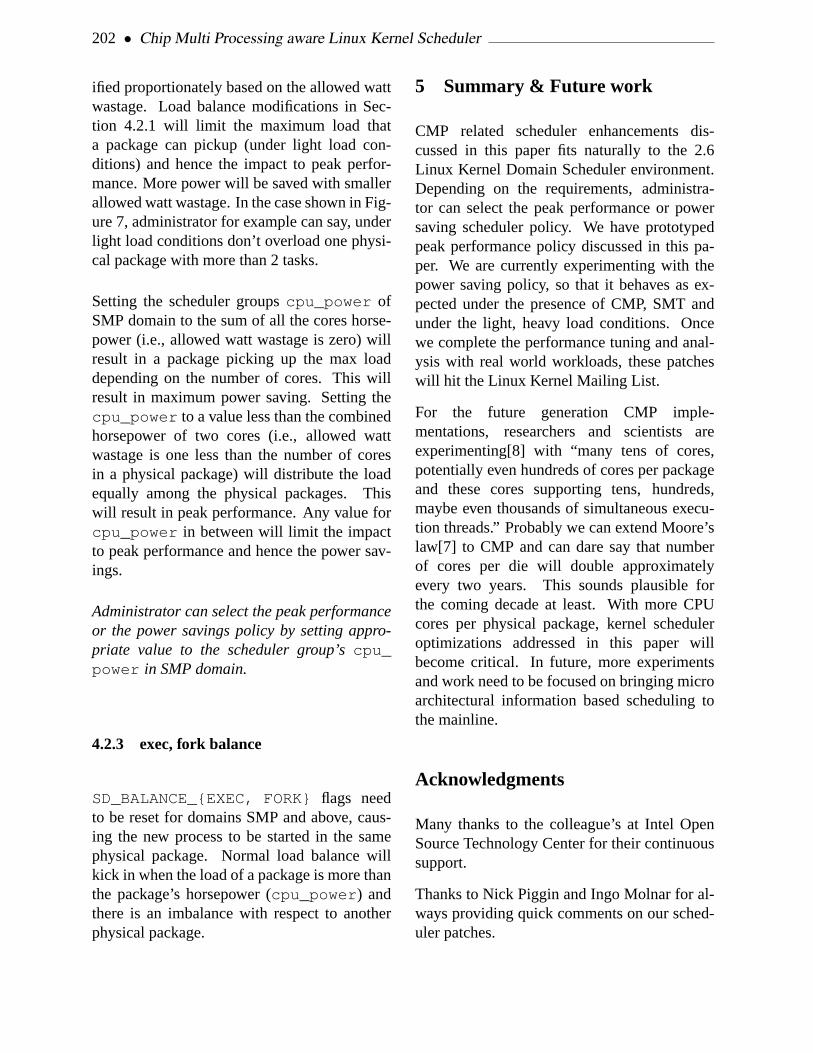
202 • Chip Multi Processing aware Linux Kernel Scheduler
ified proportionately based on the allowed wattwastage. Load balance modifications in Sec-tion 4.2.1 will limit the maximum load thata package can pickup (under light load con-ditions) and hence the impact to peak perfor-mance. More power will be saved with smallerallowed watt wastage. In the case shown in Fig-ure 7, administrator for example can say, underlight load conditions don’t overload one physi-cal package with more than 2 tasks.
Setting the scheduler groupscpu_power ofSMP domain to the sum of all the cores horse-power (i.e., allowed watt wastage is zero) willresult in a package picking up the max loaddepending on the number of cores. This willresult in maximum power saving. Setting thecpu_power to a value less than the combinedhorsepower of two cores (i.e., allowed wattwastage is one less than the number of coresin a physical package) will distribute the loadequally among the physical packages. Thiswill result in peak performance. Any value forcpu_power in between will limit the impactto peak performance and hence the power sav-ings.
Administrator can select the peak performanceor the power savings policy by setting appro-priate value to the scheduler group’scpu_power in SMP domain.
4.2.3 exec, fork balance
SD_BALANCE_{EXEC, FORK} flags needto be reset for domains SMP and above, caus-ing the new process to be started in the samephysical package. Normal load balance willkick in when the load of a package is more thanthe package’s horsepower (cpu_power ) andthere is an imbalance with respect to anotherphysical package.
5 Summary & Future work
CMP related scheduler enhancements dis-cussed in this paper fits naturally to the 2.6Linux Kernel Domain Scheduler environment.Depending on the requirements, administra-tor can select the peak performance or powersaving scheduler policy. We have prototypedpeak performance policy discussed in this pa-per. We are currently experimenting with thepower saving policy, so that it behaves as ex-pected under the presence of CMP, SMT andunder the light, heavy load conditions. Oncewe complete the performance tuning and anal-ysis with real world workloads, these patcheswill hit the Linux Kernel Mailing List.
For the future generation CMP imple-mentations, researchers and scientists areexperimenting[8] with “many tens of cores,potentially even hundreds of cores per packageand these cores supporting tens, hundreds,maybe even thousands of simultaneous execu-tion threads.” Probably we can extend Moore’slaw[7] to CMP and can dare say that numberof cores per die will double approximatelyevery two years. This sounds plausible forthe coming decade at least. With more CPUcores per physical package, kernel scheduleroptimizations addressed in this paper willbecome critical. In future, more experimentsand work need to be focused on bringing microarchitectural information based scheduling tothe mainline.
Acknowledgments
Many thanks to the colleague’s at Intel OpenSource Technology Center for their continuoussupport.
Thanks to Nick Piggin and Ingo Molnar for al-ways providing quick comments on our sched-uler patches.

2005 Linux Symposium • 203
References
[1] Active load balance modification in pre2.6.12 -mm kernels.http://www.ussg.iu.edu/hypermail/linux/kernel/0503.1/0057.html .
[2] Advanced configuration and power interfacespec 3.0.http://www.acpi.info/DOWNLOADS/ACPIspec30.pdf .
[3] Balance on exec and fork in pre 2.6.12 -mmkernels.http://www.ussg.iu.edu/hypermail/linux/kernel/0502.3/0037.html .
[4] Intel dual-core processors.http://www.intel.com/technology/computing/dual-core .
[5] Intel hyper-threading technology.http://www.intel.com/technology/hyperthread .
[6] Linux kernel.http://www.kernel.org .
[7] Moore’s law. http://www.intel.com/research/silicon/mooreslaw.htm .
[8] Processor and platform evolution for the nextdecade.http://www.intel.com/technology/techresearch/idf/platform-2015-keynote.htm .
[9] Daniel Nussbaum Alexandra Fedorova,Christopher Small and Margo Seltzer.ChipMultithreading Systems Need a NewOperating System Scheduler. SIGOPS, ACM,2004.
[10] Jun Nakajima and Venkatesh Pallipadi.Enhancements for Hyper-ThreadingTechnology in the operating System: Seekingthe Optimal Scheduling. WIESS, USENIX,December 2002.

204 • Chip Multi Processing aware Linux Kernel Scheduler

SeqHoundRWeb.py: interface to a comprehensive onlinebioinformatics resource
Peter St. OngeUniversity of Toronto
pete@{seul.org|economics.utoronto.ca}
Paul [email protected]
Abstract
In the post-genomic era, getting useful answersto challenging biological questions often de-mands significant expertise and resources notonly to acquire the requisite biological databut also to manage it. The storage requiredto maintain a workable genomic or proteomicdatabase is usually out of reach for most bi-ologists. Some toolsets already exist to facil-itate some aspects of data analysis, and oth-ers for access to particular data stores (e.g.,NCBI Toolkit), but there is a substantial learn-ing curve to these tools and installation is oftennon-trival. SeqHoundRWeb.py grew out of acommon frustration in bioinformatics—the ini-tiate bioinformaticist often has substantial bio-logical knowledge, but little experience in com-puting; Python is often held up as a good firstscripting language to learn, and in our experi-ence new users can be productive fairly rapidly.
Introduction
The discovery of DNA by Watson and Crickmarked the beginnings of massive upheaval inbiology, and ultimately, in the ways biologistswork. Research today, in the so-called post-genomic era, has embraced computing technol-
ogy as never before, with repercussions affect-ing all areas of biology[15].
One of the greatest hurdles a novice bioinfor-maticist must face is the learning curve whenlearning an approach to biology that does notinvolve the use of any of the classical or well-known laboratory techniques.
Perl is probably the most commonly usedbioinformatics language currently[13], and hassubstantial and rich object-oriented facilitiesto deal with biological data[2]. While Perlis highly versatile and effective in the handsof experienced bioinformaticists[14], my ex-perience shows that initiates to programmingthrough academic bioinformatics courses oftenhave considerable difficulty understanding thebreadth of Perl approaches and idioms suffi-ciently for it to be useful.
Like Perl, other languages have seen special-ized facilities to handle biological informa-tion develop considerably. Java[1], Ruby[4],Python[3], amongst others, all have have beenused successfully in research projects. In par-ticular, use of Python is becoming increasinglycommonplace in research[12].
A second issue is the ability to obtainand effectively exploit data in order to testthe research hypotheses of interest. Fortu-nately, there are many research sites provid-
• 205 •

206 • SeqHoundRWeb.py: interface to a comprehensive online bioinformatics resource
ing substantial data for research use, includ-ing the US National Center for Biotechnol-ogy Information[7] (NCBI), the Gene OntologyConsortium[5] (GO) and the European Bioin-formatics Institute[8] (EBI). Each of these siteshost a considerable amount of data, in both sizeand breadth, typically database table dumps al-lowing others to reconstitute and further de-velop the data for individual research needs.Although the data files are normally well un-der a gigabyte in size (compressed), typicalprocessing requires some skill even for simpleparsing and data work up, particularly becauseof the file sizes involved.
Not surprisingly, most research questions tendto be more complex and require more ro-bust approaches to managing data, such asrelational databases (e.g. MySQL and Post-GreSQL) which in turn often mean having sub-stantial hardware and some system administra-tion skills.
Other types of data processing, such asgenome-level comparisons between speciesthrough Basic Local Alignment SearchTool[10] (BLAST) can be highly CPU inten-sive for hours or even days depending on thesize of the genomes being searched and theunderlying hardware. As this data updates onan ongoing basis, the need to rebuild result setsdictates the availability of large quantities ofsubstantial computing power.
One project to assemble much of the data fromthese various sources and carry out many ofthe more demanding data process steps wasSeqHound[11], merging biological sequence(genomic and proteomic), taxonomy, annota-tion and 3-D structure within an object-orienteddatabase management system and exposed viaa web-based API. Although most of SeqHoundis F/OSS, hosting it locally locally would bedifficult for most researchers without substan-tial hardware and technical expertise, as thecurrent (as of Oct ’04) recommendation is to
have a system able to store some 650 GB ofdata[9].
In order to make access to SeqHound simplerfor novice bioinformaticists, my approach wasto trade off some speed for flexibility, and builda Python wrapper around SeqHound’s HTTPAPI, exposing much of the rich data providedby SeqHound to the ease-of-use of Python andits language features.
Overview
The primary prerequisites for SeqHoundR-Web.py are the urllib and os modules, so thismeans that SeqHoundRWeb.py should be ableto work on any platform supported by Python.Installation of the package will be via the typi-cal Python installation techniques, and we ex-pect that it will be made available throughthe normal distribution channels soon. Untilthen, the code can be imported into Python,as shown below as long as the location of theSeqHoundRWeb.py file is provided—novicePython users can take full advantage of thefunctions provided in this module without theneed for root or Administrator-level access!
Table 1 shows a straightforward example of re-trieval of a GenInfo (GI) identifier given a par-ticular accession number for a hypothetical pro-tein for a species of rat (specifically, the Nor-way Rat,Rattus norvegicus).
Acknowledgements
This project came about thanks to a number ofpeople: Alexander Ignachenko, Shaun Ghanny,Robin Haw, Henry Ling, Bianca Tong, KayuChin, Thomas Kislinger, and Ata Ghavidel allprovided constructive criticism and support, for

2005 Linux Symposium • 207
import osimport SeqHoundRWeb
# Set the proper URL for seqhoundos.environ["SEQHOUNDSITE"] = "http://seqhound.blueprint.org"
accs = ["CAA28783","CAA28784","CAA28786"
]
for acc in accs:result = SeqHoundRWeb.SeqHoundFindAcc([acc])if result[0] == ’SEQHOUND_OK’: # found it
print result[1]
Table 1: Simple SeqHoundRWeb Example - Rat
which I remain grateful. Katerina Michalick-ova, Michel Dumontier and others from theHogue Lab at Mount Sinai Hospital for cre-ating SeqHound and exposing its functionalityvia HTTP. An initial proof of concept, whichbecame the basis for this project, was built inthe Emili Lab at the University of Toronto, andI would like to thank the Department of Eco-nomics for allowing me the opportunity to con-tinue working on it as part of my professionalresponsibilities. Thanks also to Alex Brotman,Ales Hvezda and others from the SEUL Projectfor their keen eyes in finding mistakes in thetext. Any errors or omissions are, of course,my own[6].
References
[1] BioJava web site.http://www.biojava.org/ .
[2] BioPerl web site.http://bio.perl.org/ .
[3] BioPython web site.http://www.biopython.org/ .
[4] BioRuby web site.http://www.bioruby.org/ .
[5] Gene Ontology Consortium FTP site.http://archive.godatabase.org/latest-full/ .
[6] It’s All Pete’s Fault website.http://www.itsallpetesfault.org/ .
[7] NCBI FTP site.http://www.ncbi.nlm.nih.gov/Ftp/ .
[8] Catherine Brooksbank, Evelyn Camon,Midori A. Harris, Michele Magrane,Maria Jesus Martin, Nicola Mulder,Claire O’Donovan, Helen Parkinson,Mary Ann Tuli, Rolf Apweiler, EwanBirney, Alvis Brazma, Kim Henrick,Rodrigo Lopez, Guenter Stoesser, PeterStoehr, and Graham Cameron. TheEuropean Bioinformatics Institute’s dataresources.Nucl. Acids Res., 31(1):43–50,2003.

208 • SeqHoundRWeb.py: interface to a comprehensive online bioinformatics resource
[9] Ian Donaldson, Katerina Michalickova,Hao Lieu, Renan Cavero, MichelDumontier, Doron Betel, Ruth Isserlin,Marc Dumontier, Michael Matan, RongYao, Zhe Wang, Victor Gu, and ElizabethBurgess. The SeqHound Manual,Release 3.01, October 2004.
[10] Mark Yandell Ian Korf and JosephBedell. BLAST. O’Reilly, 2003.
[11] Katerina Michalickova, Gary Bader,Michel Dumontier, Hao Lieu, DoronBetel, Ruth Isserlin, and ChristopherHogue. Seqhound: biological sequenceand structure database as a platform forbioinformatics research.BMCBioinformatics, 3(1):32, 2002.
[12] J. Daniel Navarro, Vidya Niranjan, SurajPeri, Chandra Kiran Jonnalagadda, andAkhilesh Pandey. From biologicaldatabases to platforms for biomedicaldiscovery.Trends in Biotechnology,21(6):263–268, 2003.
[13] James Tisdall.Beginning Perl forBioinformatics. O’Reilly, 2001.
[14] James D. Tisdall.Mastering Perl forBioinformatics. O’Reilly, 2003.
[15] Johnathan D. Wren. Engineering ingenomics.IEEE Engineering inMedicine and Biology Magazine, pages87–98, March/April 2004.

Ho Hum, Yet Another Memory Allocator. . .Do We Need Another Dynamic Per-CPU Allocator?
Ravikiran G [email protected]
Dipankar SarmaLinux Technology Center, IBM India Software Lab
Manfred [email protected]
Abstract
The LinuxR© kernel currently incorporatesa minimalistic slab-based dynamic per-CPUmemory allocator. While the current alloca-tor exists with some applications in the form ofblock layer statistics and network layer statis-tics, the current implementation has issues.Apart from the fact that it is not even guar-anteed to be correct on all architectures, thecurrent implementation is slow, fragments, anddoes not do true node local allocation. A newper-CPU allocator has to be fast, work wellwith its static sibling, minimize fragmentation,co-exist with some arch-specific tricks for per-CPU variables and get initialized early enoughduring boot up for some users like the slab sub-system. In this paper, we describe a new per-CPU allocator that addresses all issues men-tioned above, along with possible uses of thisallocator in cache friendly reference counters(bigrefs), slab head arrays, and performancebenefits due to these applications.
1 Introduction
The Linux kernel has a number of alloca-tors, including the page allocator for allocatingphysical pages, the slab allocator for allocat-ing objects with caching, and vmalloc alloca-tor. Each of these allocators provide ways tomanage kernel memory in different ways. Withthe introduction of symmetric multi-processing(SMP) support in the Linux kernel, managingdata that are rarely shared among processorsbecame important. While statically allocatedper-CPU data has been around for a while, sup-port for dynamic allocation of per-CPU datawas added during the development of 2.6 ker-nel. Dynamic allocation allowed per-CPU datato be used within dynamically allocated datastructures making it more flexible for users.
The dynamic per-CPU allocator in the 2.6 ker-nel was, however only the first step toward bet-ter management of per-CPU data. It was a com-promise given that the use of dynamically allo-cated per-CPU data was limited. But with theneed for per-CPU data increasing and supportfor NUMA becoming important, we decided torevisit the issue.
• 209 •

210 • Ho Hum, Yet Another Memory Allocator. . .
In this paper, we present a new dynamic per-CPU data allocator that saves memory by in-terleaving objects of the same processor, sup-ports allocating objects from memory close tothe CPUs (for NUMA platforms), works duringearly boot and is independent of the slab allo-cator. We also show it allows implementationof more complex synchronization primitiveslike distributed reference counters. We discusssome preliminary results and future course ofaction.
2 Background
Over the years, CPU speed has been increas-ing at a much faster rate then speed of mem-ory access. This is even more important inmulti-processor systems where accessing mem-ory shared between the processors could besignificantly more costly if the correspondingcache line is not available in that processor’scache.
Operation Cost (ns)
Instruction 0.7Clock Cycle 1.4L2 Cache Hit 12.9Main Memory 162.4
Table 1: 700 MHz P-III Operation Costs
Table 1 shows the cost of memory opera-tions on a 700 MHz Pentium
TMIII processor.
When global data is shared between proces-sors, cache lines bouncing between processorsreduce memory bandwidth and thereby nega-tively impact scalability. As scalability im-proved during the development of the 2.6 ker-nel, the need for efficient management of in-frequently shared data also increased. The firststep towards this was interleaved static per-CPU areas proposed by Rusty Russell [3]. This
struct abc *ptr = alloc_percpu(struct abc);
cpu_to_node(i)); kmem_find_general_cachep(size, GFP_KERNEL)kmem_cache_alloc_node(
struct percpu_data.ptrs[]
NR_CPUS
Figure 1: Current allocator
allowed better management of cache lines bysharing them between CPU-local versions ofdifferent objects. As the need for per-CPU dataincreased beyond what could be declared stati-cally, the first RFC for a dynamic per-CPU dataallocator was proposed [6] along with a refer-ence implementation [7].
Subsequent discussions led to a simplified im-plementation of a dynamic allocator in the 2.5kernel as shown in Figure 1. This allocator pro-vides an interfacealloc_percpu() that re-turns a pointer cookie. The pointer cookie isthe address of an array of pointers to CPU-localobjects each corresponding to a CPU in thesystem. The array and the CPU-local objectsare allocated from the slab. Simplicity was themost important factor with this allocator, but itclearly had a number of problems.
1. The slab allocations are no longer paddedto cache line boundaries. This means thatthe current implementation would lead tofalse sharing.
2. An additional memory access (array ofCPU-local object pointers) has a perfor-mance penalty, mostly due to associativitymiss.
3. The array itself is not NUMA-friendly.

2005 Linux Symposium • 211
4. It wastes space.
We therefore implemented a new dynamic al-locator that worked around the problems ofthe current one. This allocator is based onthe reference implementation [7] published ear-lier. The key improvement has been the use ofpointer arithmetics to determine the address ofthe CPU-local objects, which reduces derefer-encing overhead.
3 Interleaved Dynamic Per-CPUAllocator
3.1 Design Goals
In order to address the inadequacies in the cur-rent per-CPU allocation schemes in the Linuxkernel, a new allocator must do the following:
1. Fast pointer dereferencing to get to theper-CPU object
2. Allocate node local memory for all CPUs
3. Save on memory, minimize fragmentation,maximize cache line utilization
4. Work well with CPU hotplug and memoryhotplug, sparse CPU numbers.
5. Get initialized early during boot
6. Independent of the slab allocator
7. Work well with its static sibling (static per-CPU areas)
A typical memory allocator returns a record(usually a pointer) that can be used to access theallocated object. A per-CPU allocator needs toreturn a record that can be used to access every
BLOCK_MANAGEMENT_SIZE
BLOCK
PCPU_BLK_SIZE
PCPU_BLK_SIZE
CONTIGUOUS VM SPACE
obj1
objN
CPU0 CHUNK
obj1
CPU1 CHUNK
objNobj1
CPU2 CHUNK
objNobj1
CPU3 CHUNK
objNobj1
CPUn CHUNK
objN
BLOCK MANAGEMENT
memory/pages
memory/pages
memory/pages
CPU0 local
CPU1 local
CPUN local
Figure 2: A block
copy of the object’s private data to the corre-sponding CPU. In our allocator, this record is acookie and the CPU-local versions of the allo-cated objects can be accessed using it. Deref-erencing speeds are very important, since thisis the fast path for all users of per-CPU data.The CPU-local versions of the object also needto be allocated from the memory nearest to theCPU on NUMA systems. Also, in order toavoid the overhead of an extra memory accessin the current per-CPU data implementation,we needed to use pointer arithmetics to accessthe object corresponding to a given CPU. Thepointer arithmetic should be simple and shoulduse as few CPU cycles as possible.
3.2 Allocating a Block
The internal allocation unit of the interleavedper-CPU allocator is ablock . Requests forper-CPU objects are served from ablock ofmemory. Theblock s are allocated on demandfor new per-CPU objects. Ablock is a con-tiguous virtual memory space (VA space) thatis reserved to contain a chunk of objects cor-responding to every CPU. It also contains ad-ditional space that is used to maintain internalstructures for managing the blocks.

212 • Ho Hum, Yet Another Memory Allocator. . .
Figure 2 shows the layout of ablock . The VAspace within ablock consists of two sections:
1. The top section consists ofNR_CPUchunks of VA space each of sizePCPU_BLK_SIZE . PCPU_BLKSIZE is a com-pile time constant. It represents the capac-ity of oneblock . Each CPU has one suchper-CPU chunk within ablock . Cur-rently the size of each per-CPU chunk istwo pages. PCPU_BLKSIZE is the sizelimit of a per-CPU object.
2. The bottom section of ablock con-sists of memory used to maintain theper-CPU object buffer control informationfor this block and plus block descrip-tor size. This section is of sizeBLOCK_MANAGEMENT_SIZE.
While the VA for the entireblock is allo-cated, the actual pages for each per-CPU chunkare allocated only if the corresponding CPU ispresent in thecpu_possible_mask . Thishas two benefits—it avoids unnecessary wasteof memory and each chunk can be allocated soit is closest to the corresponding CPU.alloc_page_node() is used to get pages nearest tothe CPU. The management pages at the bottomof a block are always allocated. Once thepages are allocated, VA space is then mappedwith pages for the CPU-local chunks.
Also, as shown in Figure 3, there won’t be map-pings for any VA space corresponding to CPUsthat are “not possible” on the system. The VAspace is contiguous forNR_CPUSprocessorsand this allows us to use pointer arithmetics tocalculate the address of an object correspond-ing to a given CPU. We also save memoryby not allocating for CPUs that are not in thecpu_possible mask.
���������������������������������������������������������������������������������������������������������������������������������������������������������������������������������������������������������������������������������������������������������������������
���������������������������������������������������������������������������������������������������������������������������������������������������������������������������������������������������������������������������������������������������������������������
���������������������������������������������������������������������������������������������������������������������������������������������������������������������������������������������������������������������������������������������������������������������
���������������������������������������������������������������������������������������������������������������������������������������������������������������������������������������������������������������������������������������������������������������������
��������������������������������������������������������������������������������������������������������������������
��������������������������������������������������������������������������������������������������������������������
��������������������������������������������������������������������������������������������������������������������
��������������������������������������������������������������������������������������������������������������������
����������������������������������������������������������������������������������������������������������������
����������������������������������������������������������������������������������������������������������������
������������������������������������������������������������������
������������������������������������������������������������������ � � � � � � � � � � � � � � � � � � � �
��������������������������������������������
������������������������������������������������������������������
���������������������������������������������������������������������������������������������������
���������������������������������
��������������������������������������������
��������������������������������������������������������������������������������������������������������������
������������������������������������������������������������������
���������������������������
���������������������������
���������������������������������������������������������
���������������������������������������������������������
CPU 0Node Local
CPU 1
Empty
Empty
CPU4
Node Local
Node Local
BlockManagement
X NR_CPUS
NUMA MP
CPU5 CPU4
CPU1 CPU0
Node Local
PCPU_BLK_SIZE
BLK_MANAGEMENT_SIZE
VIRTUALLY CONTIGUOUS BLOCK
CPU5
Figure 3: Page allocation for a block
3.3 Allocating Objects from a block
The per-CPU chunks inside ablock are fur-ther divided into units ofcurrency . Acurrency is the size of the smallest objectthat can be allocated in this scheme. The cur-rency size is defined assizeof(void *) inthe current implementation. Any object in thisallocator consists of one or more contiguousunits ofcurrency .
Eachblock in the system has a descriptor as-sociated with it. The descriptor is defined asbelow:
struct pcpu_block {void *start_addr;struct page *pages[PCPUPAGES_PER_BLOCK * 2];struct list_head blklist;unsigned long bitmap[BITMAP_ARR_SIZE];int bufctl_fl[OBJS_PER_BLOCK];int bufctl_fl_head;unsigned int size_used;
};
This is embedded into the block managementpart of the block. In the current implementa-tion, it is at the beginning of the block man-agement section of ablock . Each per-CPUobject is allocated from one suchblock main-tained by the interleaved allocator. The blockdescriptor records the base effective address of

2005 Linux Symposium • 213
���������������������������������������������������������������������������������������������������������������������������������������������������
������������������������������������������������������������������������������������������������������������������������������������������������������������������������������������������������������������������������������������������������������������������������������������������������������
���������������������������������������������������������������������������������������������������������������������������������������������������
���������������������������������������������������������������������������������������������������������������������
��������������������������������������������������������������������������������������������������������������������� �������
���������������������
������������������������������������������������������������������������
������������������������������������������������������������������������
bitmap
start_addrpages[]
blklist
bufctl_fl bufctl_fl_head
Pecpu memory block
Block of memory out of which per−cpu objects\are served
struct pcpu_block
bufctls
size_used
Block management
BLOCK MANAGEMENT STRUCTURE
buf_ctls
Figure 4: Managing blocks
the block (start_addr ) as well as the al-location state of eachcurrency within theblock . The allocation state is recorded usinga bitmap wherein each bit represents an isomor-phic currency of every per-CPU chunk inthat block. There are as many bits as the num-ber ofcurrency in one chunk of the block.
Figure 4 shows the organization of the blockmanagement area. Block descriptor has anarray of pointers, each pointing to a CPU-local chunk of physical pages allocated for thisblock. Each object allocated from ablockis represented by abufctl data structure.Thesebufctl structures are embedded in theblock management section of theblock andthey start right after the block descriptor. Theblock descriptor also has an array-based freelist to allocatebufctl or object descriptors.bufctl_fl is the array-based free list andbufctl_head stores the head of this free list.
During allocation of a per-CPU object, thebitmap indicatingcurrency allocation stateis sorted and saved. This array is sorted in as-cending order of available object sizes in thatblock due to contiguouscurrency regions.This array is traversed and the first element thatfits the allocation requirement is used and the
���������������������������������������������
���������������������������������������������
���������������������������
���������������������������
���������������������������������������������������������������������������������
���������������������������������������������������������������������������������
���������������������������
���������������������������
������������������������������������������������������������
������������������������������������������������������������
���������������������������������������������������������������������������������������������������������������������������
��������������������������������������������������������������������������������������������������������������������������� � � � � � � � � � � � � � � � � � � � � � � � � � � � � � � � � � � � � � � �
���������������������������������������������������������������������������������
���������������������������
���������������������������
���������������������������
���������������������������
���������������������������������������������
���������������������������������������������
���������������������������������������������
���������������������������������������������
1 1 1 1 1 0 1 1 1 1 0 0 0 0 0
CPU0 chunk
CPU1 chunk
struct pcpu_block.bitmap
OBJ1 OBJ2
bufctl
addr
size20
next
(OBJ1)
(OBJ2)
addr
size20
next
BLOCK
OBJ1 OBJ2
OBJ2OBJ1
BLOCK
bufctl
Object block list
0xf8880000
0xf8880018
0xf8880000
Figure 5: Object layout
correspondingcurrency units are allocated.
Figure 5 shows the relation between ablockin the allocator, per-CPU objects allocated fromtheblock , the bitmap corresponding to theseobjects,bufctl structures andbufctl listfor these objects. In this example, a per-CPUblock starts at 0xf8880000. The currency sizeis assumed to be 4 (sizeof (void *) onx86). The squares in CPU chunks representthe allocator currency. The first five consecu-tive currencies make OBJ1 (shaded currenciesin the block). Each currency is represented bya bit in the bitmap. Hence, bits 0–4 of thebitmap correspond to OBJ1. OBJ1 starts at ad-dress 0xf8880000. OBJ2 starts at 0xf8888018.The figure also depicts the bufctl structures andbufctl list for OBJ1 and OBJ2.
3.4 Managing blocks
The amount of per-CPU objects served by a sin-gle block is limited. So, our allocator allowsallocation of newblock on demand. When-ever a request for a per-CPU object cannot bemet with anyblock currently in the system, anewblock is added to the system that is iso-morphic to existing ones.

214 • Ho Hum, Yet Another Memory Allocator. . .
Sorted list of allocator blocks
firstnotfull
Memory used
Figure 6: Managing block lists
These blocks are linked to one another in acircular doubly linked sorted list (Figure 6).pcpu_block counts the amount of memoryused in the block (size_used ). This list issorted in descending order usingsize_used .Thefirstnotfull field contains the list po-sition of the firstblock in the list that hasavailable memory for allocation. On an al-location request, the list traversed from thefirstnotfull position and the first avail-able block with sufficient space is chosen forallocation. If no such block is found, a newblock is created and added to this list. Theblocks are repositioned in the list to preservethe sorted nature of the list upon every allo-cation and free request. During the course offreeing per-CPU objects, if the allocator noticesthatblkp->size_used goes to zero, the en-tire block—VA space, per-CPU pages, blockmanagement pages and the VA mapping are de-stroyed.
3.5 Accessing Per-CPU Data
A per-CPU allocation returns a pointer that isused as a cookie to access CPU-local versionof the object for any given CPU. This pointereffectively points to address of the CPU-local
object for CPU 0. To get to the CPU-localversion of CPU N, the following arithmeticsis used—cpu_local_address = p + N *
PCPU_BLKSIZE, where p is the cookie re-turned by the interleaved allocator. SincePCPU_BLKSIZE is a carefully chosen com-pile time constant of a proper page order, theabove arithmetics is optimized to a simple addand bit shift operations. The most expensiveoperation in accessing the CPU-local object isusually the determination of the current CPUnumber (smp_processor_id() ). This istrue for static per-CPU areas as well. To avoidthe cost ofsmp_processor_id() duringper-CPU data access, kernel developers likeRusty Russell have been contemplating usinga dedicated processor register to get a handle tothat processor’s CPU-local data. The currentstatic per-CPU area in the Linux kernel usesan array (__per_cpu_offset[] ) to storea handle to each CPU’s per-CPU data. Witha dedicated processor register,__per_cpu_offset[cpuN] would be loaded into the reg-ister and users of per-CPU data would not needto make a call tosmp_processor_id() toget to the CPU-local versions—simple arith-metic on the contents of the processor ded-icated register will suffice. In fact,smp_processor_id() could be derived from theregister based__per_cpu_offset[] ta-ble. This scheme can co-exist with our per-CPU allocator.
4 Using Dynamic Per-CPU Alloca-tor
4.1 Per-CPU structures within the slab al-locator
The Linux slab allocator uses arrays of objectpointers to speed up object allocation and re-lease. This avoids doing costly linked list or

2005 Linux Symposium • 215
struct kmem_cache_s {struct array_cache *array[NR_CPUS];/* ... additional members, only
* touched from slow path ... */};struct array_cache {
unsigned int avail;unsigned int limit;void * objects[];
};
Table 2: Main structures in the fast-path—before
spinlock operations in each operation. Each ob-ject cache contains one array for each CPU. Ifan array is not empty, then an allocation littlemore than looking up the per-CPU array andreturning one entry from that array. There-fore the time required for the pointer lookupis the most significant part of the executiontime for kmem_cache_alloc and kmem_cache_free .
At present, the lookup code mimics the imple-mentation of the dynamic per-CPU variables:kmem_cache_create returns a pointer tothe structure that contains the array of pointersto the per-CPU variables. Each allocation orrelease looks up the correct per-CPU structureand returns an object from the array. Table 2shows the (slightly simplified) structures.
While this is a simple implementation, it hasseveral disadvantages:
• It is a code duplication and it would be bet-ter if slab could reuse the primitives pro-vided by the dynamic per-CPU variables.This is not possible, because it would cre-ate a cyclic dependency: the dynamic per-CPU variable implementation relies on theslab allocator for its own allocations.
• It is a simple per-CPU allocator, thereforeeach access required a table lookup. De-pending on the value ofNR_CPUS, theremight be even frequent write operations,
struct kmem_cache_s { /* per-CPU variable */struct kmem_globalcache *global;unsigned int avail;unsigned int limit;void * objects[];
};struct kmem_globalcache { /* one instance */
/* ... additional members, only* touched from slow path ... */
};
Table 3: Main structures for fast-path—after
and thus cache line transfers on the cacheline that contains the table.
• The implementation is fixed withinslab.c , it’s not possible to override itwith arch specific code, even if an archi-tecture supports a fast per-CPU variablelookup.
Therefore the slab code was rearranged touse per-CPU variables natively for the ob-ject caches:kmem_cache_create returnsthe pointer to the per-CPU structure that con-tains the members that are needed in the fast-path of the allocator. The other membersare stored in a new structure (structkmem_globalcache ). The new structure layout isshown in Table 3.
The functionskmem_cache_alloc() andkmem_cache_free() only need to accessavail , limit , andobjects , thus there areno accesses to the global structure from thefast-path.
4.2 Statistics counters
As part of the scalable statistics counter workwe carried out earlier, it has already been es-tablished that per-CPU data is useful for ker-nel statistics counters, and solves the problemof cache line bouncing on NUMA and multi-processor systems [5]. During the development

216 • Ho Hum, Yet Another Memory Allocator. . .
of the 2.6 kernel, a number of kernel statisticswere converted to use a dynamic per-CPU al-locator. These include networking MIBs, diskstatistics and thepercpu_counter used inext2 and ext3 filesystems. With our allocator,the per-CPU statistics counters become moreefficient. In addition to faster dereferencing andnode-local allocation, our allocator savesNR_
CPUS x sizeof(void *) bytes of memoryfor each per-CPU counter by avoiding the arraystoring the CPU-local object pointers.
4.3 Distributed reference counters (bi-grefs)
Rusty Russell has an experimental patch thatmakes use of the dynamic per-CPU memoryallocator to avoid global atomic operations onreference counters[4].
A “bigref” reference counter would con-sist of two counters internally; one of typeatomic_t which is the global counter, andanother per-CPU counter of typelocal_t ,the distributed counter. Per-CPU memory forthe local_t is allocated when the bigref ref-erence counter is initialized. The referencecounter usually operates in the “fast” mode—it just increments or decrements the CPU-local local_t counter whenever the bigrefreference counter needs to be incremented ordecremented (get() andput() operations inLinux parlance). This operation onlocal_tper-CPU counters is much cheaper comparedto operations on a globalatomic_t type. Infact on x86, local increment is just anincl in-struction.
The reference counter switches to a “slow”mode when the element being protected by thereference counter is no longer needed in thesystem and is being released or ’disowned’.This switch from fast mode to slow mode isdone by usingsynchronize_kernel() to
make sure all CPUs recognize slow mode op-eration before the ’disowning’ completes. Thereference counter is biased with a high valueby setting theatomic_t counter with the highbias value before the switch to slow mode is ini-tiated. In fact this biasing itself indicates begin-ning of the switch. This bias value is subtractedfrom the reference counter after the switch toslow mode.
Bigrefs save on space and dereference speedswhen they use our per-CPU allocator. In ad-dition to space saving, our allocator interlacescounters on cache lines too, which results in in-creased cache utilization.
5 Results
5.1 Slab enhancements
The new slab implementation discussed inSection 4.1 was tested with both micro-benchmarks and real-world test loads.
• Micro-benchmarks showed no change be-tween the old and the new implemen-tation; In a tight loop,kmem_cache_alloc needed around 35 CPU cycles onan 64-bit AMD Athlon
TM. The lack of im-
provement is not unexpected because a ta-ble lookup is only slow on a cache miss.
• Tests with tbench (version 3.03 withwarm-up) on a 4-CPU HT Pentium 4(2.8GHz Xeon) system showed an im-provement of around 1%.
6 Future Work
The new allocator is not without its own limita-tions:

2005 Linux Symposium • 217
1. One major drawback of our allocator de-sign is increased TLB footprint. Since ourallocator uses the Linux vmalloc VM areato stitch all node local and block man-agement pages into one contiguous block,hot per-CPU data may take too many TLBentries when there are too many alloca-tor blocks within the system. Node-localpage allocation and fast dereferencing areof utmost importance, so we have to usea virtually contiguous area for fast pointerarithmetic. But to limit the increased TLBusage, in the future, we may want to uselarge pages for blocks, and fit all per-CPUdata in one block. This way, we can limitthe number of TLB entries taken up by thedynamic per-CPU allocator.
2. The allocation operation is slow. It is notdesigned for allocation speed. It is de-signed for maximum utilization and min-imum fragmentation. Given the currentusers of dynamic per-CPU allocator, itmay not be valuable to improve allocationoperation.
With the interleaved dynamic per-CPU alloca-tor, it has also become possible to implementdistributed locks [1] [2] and reference coun-ters [4].
7 Conclusion
The interleaved per-CPU allocator we imple-mented is a step forward from where we arein the Linux kernel. The current allocator inthe Linux kernel leads to false sharing and it isnot optimized. Our allocator overcomes all ofthose problems. As the Linux kernel matures,this will allow use of more sophisticated prim-itives in the Linux kernel without adding anyoverhead. The design has evolved over a num-ber of discussions and it is mature enough tohandle all architectures.
8 Acknowledgments
Rusty Russell started the ball rolling by first im-plementing the static per-CPU areas and lateradvising us. We thank him for all of his contri-butions. We would also like to thank a numberof Linux kernel hackers, including Dave Millerand Andrew Morton, all of whom advised us inmany different situations. We are indebted toGerrit Huizenga, Paul McKenney, Jim WaskoJr., and Vijay Sukthankar for being so support-ive of this effort.
9 Legal Statement
This work represents the view of the authors anddoes not necessarily represent the view of IBM.
IBM is a registered trademark of International Busi-ness Machines Corporation in the United States,other countries, or both.
Linux is a registered trademark of Linus Torvalds.
Pentium is a registered trademark of Intel Corpora-tion in the United States, other countries or both.
AMD Athlon is a registered trademark of AdvancedMicro Devices Inc. in the United States, other coun-tries or both.
Other company, product, and service names may betrademarks or service marks of others.
References
[1] M ELLOR-CRUMMEY, J. M., AND SCOTT,M. L. Algorithms for scalablesynchronization on shared-memorymultiprocessors.Transactions ofComputer Systems 9, 1 (February 1991),21–65.

218 • Ho Hum, Yet Another Memory Allocator. . .
[2] M ELLOR-CRUMMEY, J. M., AND SCOTT,M. L. Scalable reader-writersynchronization for shared-memorymultiprocessors. InProceedings of theThird PPOPP(Williamsburg, VA, April1991), pp. 106–113.
[3] RUSSELL, R. Subject: [patch] 2.5.1-pre5:per-cpu areas. Available:http://marc.theaimsgroup.com/?l=linux-kernel&m=100759080903883&w=2 , December2001.
[4] RUSSELL, R. Subject: Re: [patch] mm:Reimplementation of dynamic percpumemory allocator. Available:http://marc.theaimsgroup.com/?l=linux-kernel&m=110569951013489&w=2 , January2005.
[5] SARMA , D. Scalable statistics counters.Available:http://lse.sourceforge.net/counters/statctr.html , May2002.
[6] SARMA , D. Subject: [lse-tech] [rfc]dynamic percpu data allocator. Available:http://marc.theaimsgroup.com/?l=lse-tech&m=102215919918354&w=2 , May 2002.
[7] SARMA , D. Subject: [rfc][patch]kmalloc_percpu. Available:http://marc.theaimsgroup.com/?l=linux-kernel&m=102761936921486&w=2 , July 2002.

Beagle: Free and Open Desktop Search
Jon TrowbridgeNovell
Abstract
I will be discussing Beagle, a desktop searchsystem that is currently being developed byNovell. It acts as a search aggregator, pro-viding a simple API for simultaneously query-ing multiple data sources. Pluggable backendsdo the actual searching while Beagle handlesthe details, such as consolidating and rankingthe hits and passing them back to client appli-cations. Beagle includes a core set of back-ends that build full-text indexes of your per-sonal data, allowing you to efficiently searchyour files, e-mail, contacts, calendar, IM logs,notes and web history. These indexes are up-dated in real time to ensure that any search re-sults will always reflect the current state of yourdata.
Check Online
This author did not provide the body of this paper by deadline. Please check online for any updates.
• 219 •

220 • Beagle: Free and Open Desktop Search

Glen or GlendaEmpowering Users and Applications with Private Namespaces
Eric Van HensbergenIBM Research
Abstract
Private name spaces were first introduced intoL INUX during the 2.5 kernel series. Their usehas been limited due to name space manipu-lation being considered a privileged operation.Giving users and applications the ability to cre-ate private name spaces as well as the ability tomount and bind resources is the key to unlock-ing the full potential of this technology. Thereare serious performance, security and stabilityissues involved with user-controlled dynamicprivate name spaces in LINUX . This paper pro-poses mechanisms and policies for maintain-ing system integrity while unlocking the powerof dynamic name spaces for normal users. Itdiscusses relevant potential applications of thistechnology including its use with FILESYSTEM
IN USERSPACE[24], V9FS[8] (the LINUX portof the PLAN 9 resource sharing protocol) andPLAN 9 FROM USER SPACE[4] (the PLAN 9application suite including user space syntheticfile servers ported to UNIX variants).
1 What’s in a name?
Names are used in all aspects of computerscience[21]. For example, they are used to ref-erence variables in programing languages, in-dex elements in a database, identify machines
in a network, and reference resources withina file system. Within each of these cate-gories names are evaluated in a specific con-text. Program variables have scope, databaseindexes are evaluated within tables, networksmachine names are valid within a particulardomain, and file names provide a mapping tounderlying resources within a particularnamespace. This paper is primarily concerned withthe evaluation and manipulation of names andname space contexts for file systems under theL INUX operating system.
File systems evolved from flat mappings ofnames to multi-level mappings where each cat-alog (or directory) provided a context for nameresolution. This design was carried furtherby MULTICS[1] with deep hierarchies of di-rectories including the concept of links be-tween directories within the hierarchy[5]. Den-nis Ritchie, Rudd Canaday and Ken Thomp-son built the first UNIX file system basedon MULTICS, but with an emphasis onsimplicity[22]. All these file systems had a sin-gle, global name space.
In the late 1980s, Thompson joined with RobPike and others in designing the PLAN 9 oper-ating system. Their intent was to explore po-tential solutions to some of the shortcomingsof UNIX in the face of the widespread use ofhigh-speed networks[19]. It was designed fromfirst principles as a seamless distributed system
• 221 •

222 • Glen or Glenda
with integrated secure network resource shar-ing.
The configuration of an environment to useremote application components or services inplace of their local equivalent is achieved with afew simple command line instructions. For themost part, application implementations operateindependent of the location of their actual re-sources. PLAN 9 achieves these goals througha simple well-defined interface to services, asimple protocol for accessing both local and re-mote resources, and through dynamic, stack-able, per-process private name spaces whichcan be manipulated by any user or application.
On the other hand, the LINUX file system namespace has traditionally been a global flat namespace much like the original UNIX operat-ing system. In November of 2000, AlexanderViro proposed implementing PLAN 9 style per-process name space bindings[28], and in lateFebruary 2001 released a patch[2] against the2.4 kernel. This code was later adopted intothe mainline kernel in 2.5. This support, whichis described in more detail in section 4, estab-lished an infrastructure for private name spacesbut restricted the creation and manipulation ofname spaces as privileged.
This paper presents the case for making namespace operations available to common usersand applications while extending the existingL INUX dynamic name space support to havethe power and flexibility of PLAN 9 namespaces. Section 2 describes the design, imple-mentation and advantages of the PLAN 9 dis-tributed system. Example applications of thistechnology are discussed in Section 3. The ex-isting LINUX support is described in more de-tail in Section 4. Perceived barriers and solu-tions to extended LINUX name space supportare covered in Section 5. Section 6 overviewsrelated work and recent proposals as alterna-tives to our approach and Section 7 summarizesour conclusions and recommendations.
2 Background: Plan 9
In PLAN 9, all system resources and interfacesare represented as files. UNIX pioneered theconcept of treating devices as files, providing asimple, clear interface to system hardware. Inthe 8th edition, this methodology was taken fur-ther through the introduction of the /proc syn-thetic file system to manage user processes[10].Synthetic file systems are comprised of ele-ments with no physical storage, that is to saythe files represented are not present as files onany disk. Instead, operations on the file com-municate directly with the sub-system or ap-plication providing the service. LINUX con-tains multiple examples of synthetic file sys-tems representing devices (DEVFS), processcontrol (PROCFS), and interfaces to system ser-vices and data structures (SYSFS).
PLAN 9 took the file system metaphor fur-ther, using file operations as the simple, well-defined interface to all system and applicationservices. The design was based on the knowl-edge that any programmer knows how to inter-act with files. Interfaces to all kernel subsys-tems from the networking stack to the graphicsframe buffer are represented within syntheticfile systems. User-space applications and ser-vices export their own synthetic file systems inmuch the same way as the kernel interfaces.Common services such as domain name ser-vice (DNS), authentication databases, and win-dow management are all provided as file sys-tems. End-user applications such as editors ande-mail systems export file system interfaces as ameans for data exchange and control. The ben-efits and details of this approach are covered ingreat detail in the existing PLAN 9 papers[18]and will be covered to a lesser extent by appli-cation examples in section 3.
9P[15] represents the abstract interface used toaccess resources under PLAN 9. It is somewhatanalogous to the VFS layer in LINUX [11].

2005 Linux Symposium • 223
In PLAN 9, the same protocol operations areused to access both local and remote resources,making the transition from local resources tocluster resources to grid resources completelytransparent from an implementation standpoint.Authentication is built into the protocol andwas extended in its INFERNO[20] derivativeStyx[14] to include various forms of encryptionand digesting.
It is important to understand that all 9P opera-tions can be associated with different active se-mantics in synthetic file systems. Traversal of adirectory hierarchy can allocate resources or setlocks. Reading or writing data to a file interfacecan initiate actions on the server. The dynamicnature of these semantics makes caching dan-gerous and in-order synchronous execution offile system operations a must.
The 9P protocol itself requires only a reliable,in-order transport mechanism to function. It iscommonly used on top of TCP/IP[16], but hasalso been used over RUDP[13], PPP[23], andover raw reliable mechanisms such as the PCIbus, serial port connections, and shared mem-ory. The IL protocol was designed specificallyto provide 9P with a reliable, in order transporton top of an IP stack without the overhead ofTCP[17].
The final key design point of PLAN 9 is theorganization of all local and remote resourcesinto a dynamic private name space. Manipulat-ing an element’s location within a name spacecan be used to configure which services to use,interpose stackable layers onto service inter-faces, and create restricted "sandbox" environ-ments. Under PLAN 9 and INFERNO, the namespace of each process is unique and can be ma-nipulated by ordinary users through mount andbind system calls.
Mount operations allow a client to attach newinterfaces and resources which can be providedby the operating system, a synthetic file server,
or from a remote server. Bind commands al-low reorganization of the existing name space,allowing certain services to be bound to well-known locations. Bind operations can sub-stitute one resource for another, for example,binding a remote device over a local one. Bind-ing can also be used to create stackable layersby interposing one interface over another. Suchinterposer interfaces are particularly useful fordebugging and statistics gathering.
The default mount and bind behavior is to re-place the mount-point. However, PLAN 9 alsoallows multiple directories to be stacked at asingle point in the name space, creating auniondirectory. Within such a directory, each compo-nent is searched to resolve name lookups. Flagsto the mount and bind operations determine theposition of a particular component in the stack.A special flag determines whether or not filecreation is allowed within a particular compo-nent.
By default, processes inherit an initial namespace from their parent, but changes made tothe child’s name space are not reflected in theparent’s. This allows each process to have acontext-specific name space. The PLAN 9 forksystem call may be called with several flags al-lowing for the creation of processes with sharedname spaces, blank name spaces, and restrictedname spaces where no new file systems can bemounted. PLAN 9 also provides library func-tions (and associated system calls) for creatinga new name space without creating a processand for constructing a name space based on afile describing mount sources, destinations, andoptions.
3 Applications
There are many areas where the pervasive useof private dynamic name spaces under PLAN 9

224 • Glen or Glenda
can be applied in similar ways under LINUX .Many of these are detailed in the foundationalPLAN 9 papers [19, 18] as well as the PLAN
9 manual pages[15]. We will step through asubset of these applications and provide someadditional potential applications in the LINUX
environment.
Under PLAN 9, one of the more straightfor-ward uses of dynamic name space is to bindresources into well-known locations. For ex-ample, instead of using a PATH environmentvariable, various executables are bound into asingle/bin union directory. PLAN 9 clustersuse a single file server providing resources formultiple architectures. Typical startup profilesbind the right set of binaries to the/bin direc-tory. For example, if you logged in on an x86host, the binaries from/386/bin would bebound to/bin , while on PPC/power/binwould be bound over bin. Then the user’s pri-vate binary directory is bound on top of the sys-tem binaries. This has a side benefit of search-ing the various directories in a single lookupsystem call versus individually walking to ele-ments in the path list from the shell.
Another use of stackable binds in PLAN 9is within a development environment. Youcan bind directories (or even individual files)with your changes over read-only versions of alarger hierarchy. You can even recursively binda blank hierarchy over the read-only hierarchyto deposit compiled object files and executa-bles. The PLAN 9 development environmentat Bell Labs has a single source tree which peo-ple bind their working directories and privateobject/executable trees over. Once they are sat-isfied with their changes, they can push themfrom the local versions to the core directories.Using similar techniques developers can alsokeep distinct groups of changes separated with-out having to maintain copies of the entire tree.
Crafting custom name spaces is also a goodway to provide tighter security controls for ser-
vices. Daemons exporting network servicescan be locked into a very restrictive namespace, thus helping to protect system integrityeven if the daemon itself becomes compro-mised. Similarly, users accessing data fromother domains over mounted file systems don’trun as much risk of other users gaining accessif they mount the resources in a private namespace. Users can craft custom sandboxes foruntrusted applications to help protect againstpotential malicious software and applets.
As mentioned earlier, PLAN 9 combines dy-namic name space with a remote resource shar-ing protocol to enable transparent distributedresource utilization. Remote resources arebound into the local name space as appropri-ate and applications run completely obliviousto what resources they are actually using. Astraightforward example of this is mountinga networked stereo component’s audio devicefrom across the room instead of using yourworkstation’s sound card before starting an au-dio jukebox application. A more practical ex-ample is mounting the external network proto-col stack of a firewall device before running aweb browser client. Since the external networkprotocol stack is only mounted for the particu-lar browser client session, other services run-ning in separate sessions with separate namespaces (and protocol stacks) are safe from ex-ternal access. The PLAN 9 paradigm of mount-ing any distributed resource and transparentlyreplacing local resources (or providing a net-work resource when a local resource isn’t avail-able) provides an interesting model for imple-menting grid and utility based computing.
Another example of this is the PLAN 9 cpu(1)command which is used to connect from a ter-minal to a cluster compute node. Note thatthis command doesn’t operate like ssh or telnet.The cpu(1) command will export to the serverthe current name space of the process fromwhich it was executed on the client. Server side

2005 Linux Symposium • 225
scripts take care of binding the correct archi-tectural binaries for the cpu server over thoseof the client terminal. Interactive I/O betweenthe cpu and the client is actually performed bythe cpu server mounting the client’s keyboard,mouse, and display devices into the session’sprivate name space and binding those resourcesover its own. Custom profiles can be used tolimit the resources exported to the cpu server,or to add resources such as local audio devicesor protocol stacks. It represents a more ele-gant approach to the problems of grid, cluster,and utility-based computing providing a mech-anism for the seamless integration and orga-nization of local resources with those spreadacross the network.
Similar approaches can be provided to virtu-alization and para-virtualization environments.At the moment, the LINUX kernel is plagued bya plethora of “virtual” device drivers supportingvarious devices for various virtualized environ-ments. Separate gateway devices are supportedfor Xen[7], VMware[30], IBM Hypervisors[3],User Moder Linux[9], and others. Additionally,each of these virtualization engines requiresseparate gateways for each class of device. ThePLAN 9 paradigm provides a unified, simple,and secure method for supporting these vari-ous virtual architectures and their device, filesystem, and communication needs. Dynamicprivate name spaces enable a natural environ-ment for sub-dividing and organizing resourcesfor partitioned environments. Application fileservers or generic plug-in kernel modules pro-vide a variety of services including copy-on-write file systems, copy-on-write devices, mul-tiplexed network connections, and commandand control structures. IBM Research is cur-rently investigating usingV9FS together withprivate name spaces and application syntheticfile servers to provide just such an approach forpartitioned scale-out clusters executing high-performance computing applications.
4 Linux Name Spaces
The private name space support added in the2.5 kernel revolved around the addition of aCLONE_NEWNSflag to the LINUX clone(2)system call. The clone(2) system call allowsthe creation of new threads which share a cer-tain amount of context with the parent process.The flags to clone specify the degree of sharingwhich is desired and include the ability to sharefile descriptor tables, signal handlers, memoryspace, and file system name space. The currentdefault behavior is for processes and threadsto start with a shared copy of the global namespace.
When theCLONE_NEWNSflag is specified, thechild thread is started with a copy of the namespace hierarchy. Within this thread context,modifications to either the parent or child’sname space are not reflected in the other. Inother words, when a new name space is re-quested during thread creation, file serversmounted by the child process will not be vis-ible in the parent’s name space. The converseis also true. In this way, a thread’s name spaceoperations can be isolated from the rest of thesystem. The use of theCLONE_NEWNSflag isprotected by theCAP_SYS_ADMINcapability,making its use available only to privileged userssuch as root.
L INUX name spaces are currently manipu-lated by two system calls:mount(2) andumount(2) . Themount(2) system call at-taches a file system to a mount-point withinthe current name space and theumount(2)system call detaches it. More recently in the2.4 kernel series, theMS_BINDflag was addedto allow an existing file or directory subtreeto be visible at other mount-points in the cur-rent name space. Both system calls are onlyvalid for users withCAP_SYS_ADMINcapa-bility, and so are predominately used only byroot. The table of mount points in a thread’s

226 • Glen or Glenda
current name space can be viewed by lookingat the/proc/xxx/mounts file.
Users may be granted the ability to mountand unmount file systems through the mount(1)application and certain flags in the fstab(5)configuration file. This support requires thatthe mount application be configured with set-uid privileges and that the exact mount sourceand destination be specified in the fstab(5).Certain network file systems (such asSMBFS,CIFS, and V9FS) which have a more user-centric paradigm circumvent this by havingtheir own set-uid mount utilities: smbmnt(8),cifs.mount(8), and 9fs(1). More recently, therehas been increased interest in user-space fileservers such as FILESYSTEM IN USERSPACE
(FUSE)[24] with its own set-uid mount appli-cation fusermount(8).
The proliferation of these various set-uid ap-plications that circumvent the kernel protectionmechanisms indicates the need to re-evaluatethe existing restrictions so that a more practi-cal set of policies can be put in place withinthe kernel. Users should be able to mount filesystems when and where appropriate. Privatename spaces seem to be a natural fit for pre-venting global name space pollution with in-dividual user mount and bind activities. Theyalso provide a certain degree of isolation fromuser mounted synthetic file systems, providingan additional degree of protection to systemdemons and other users who might otherwiseunwittingly access a malicious user-level fileserver.
Private name space support in LINUX is un-der utilized primarily due to the classificationof name space operations as privileged. It isfurther crippled by the lack of stackable namespace semantics and application file servers.Unlocking applications and environments suchas those described in Section 3 by removingsome of the restrictions enforced by the LINUX
kernel would create a much more elegant and
powerful computing environment. Addition-ally, providing a more flexible, yet consistentset of kernel enforced policies would be far su-perior to the wide range of semantics currentlyenforced by file system specific set-uid mountapplications.
5 Barriers and Solutions
PLAN 9 is not LINUX , and LINUX is not PLAN
9. There are significant security model and filesystem paradigm differences between the twosystems. Concerns related to these differenceshave been broken down into four major cate-gories: concerns with user name space manipu-lation, problems with users being able to mountarbitrary file systems, potential problems withuser file systems, and problems with allowingusers to create their own private name spaces.
5.1 Binding Concerns
The mount(1) command specified with the-bind option, hereafter referred to as a bindoperation, is an incredibly useful tool even ina shared global name space. When combinedwith the notion of private name spaces, it allowsusers and applications to craft custom environ-ments in which to work. However, the ability todynamically bind directories and/or files overone another creates several security concernsthat revolve around the ability to transparentlyreplace system configuration and common datawith potentially compromised versions.
PLAN 9 places no restrictions on bind op-erations. Users are free to bind over anysystem directory or file regardless of accesspermissions—binding writable layers over oth-erwise read-only directories can be one of themore useful operations. However, PLAN 9’s

2005 Linux Symposium • 227
authentication and system configuration mech-anisms are constructed in such a way as tonot rely on accessing files when running underuser contexts. In other words, authenticationand configuration are system services which arestarted at boot (or reside on different servers),and so aren’t affected by user manipulations oftheir private name spaces.
Under LINUX , system services are constructeddifferently and there is still heavy reliance onwell-known files which are accessed through-out user sessions. Examples include suchsensitive files as/etc/passwd and /etc/fstab .
Similar concerns apply to certain system direc-tories which multiple users may have write ac-cess to, such as/tmp or /usr/tmp . If usersare able to bind over these public directoriesunder the global name space, they could poten-tially compromise the data of another user whoinadvertently used a bound/tmp instead of thesystem/tmp .
These problems can be addressed with a sim-ple policy of only allowing a user to bind overa directory they have explicit write access to.This solves the problem of system configura-tion files, but doesn’t cover globally writablespaces such as/usr/tmp . A simple solu-tion to protecting such shared spaces is to onlyallow user initiated binds within private namespaces. A slightly more complicated form ofprotection is based on the assumption that suchpublic spaces have thesticky bitset in the di-rectory permissions.
When used within directory permissions, thesticky bit specifies that files or subdirectoriescan only be renamed or deleted by their origi-nal owner, the owner of the directory, or a priv-ileged process. This prevents users from delet-ing or otherwise interfering with each other’sfiles in shared public spaces. A simple policy to
extend this protection to user name space ma-nipulation is to return a permissions error whena normal user attempts to bind over a directoryin which the sticky bit is set.
While limiting binds to sticky-bit directories isreasonable enough, it is an unnecessary restric-tion. The use of private name spaces solves sev-eral security concerns with user-modificationsto name space, and does so without overlylimiting the user’s ability to mount over theseshared spaces. Another benefit of requiringuser binds to be within a private name spaceis that it prevents such binds from polluting theglobal system name space.
5.2 Mounting Concerns
Another set of concerns has to do with allowingusers to mount new file systems into a namespace. As discussed previously, this is some-thing currently accomplished through set-uidmount applications which check the user’s per-missions versus particular policies. A moreglobal policy would give administrators moreconsistent control over users and help eliminatethe potential problems caused by the use of set-uid applications
One of the primary problems with giving usersthe ability to mount arbitrary file systems isthe concern that they may mount a file systemwith set-uid scripts allowing them to gain ac-cess to privileged accounts (i.e., root). It isrelatively trivial for a user to construct a filesystem image, floppy, or CD-ROM on a per-sonal machine with set-uid shells. If they wereallowed to mount these on an otherwise se-cure system, they could instantly compromiseit. The existing mount applications circum-vent such a vulnerability by providing aNO-SUID flag which disables interpretation of set-uid and set-gid permission flags. A similar

228 • Glen or Glenda
mechanism enforced as the default for all user-mounts would provide a certain level of protec-tion against such an attack.
Another possible attack vector would be the im-age being mounted. Most file systems are writ-ten on the assumption that the backing store issomewhat secure and reputable. LINUX kernelcommunity members have expressed concernthat disk images could be constructed specifi-cally to crash or corrupt certain file systems, soas to disable or disrupt system activity. This isparticularly difficult to protect against, but notall file systems are vulnerable to such attacks.In particular, network file systems are writtendefensively to prevent such corruption from af-fecting the rest of the system. Such defensivelywritten file systems could be marked with anadditional file system flag marking them as safefor users to mount.
Each mounted file system uses a certain amountof system resources. Unlocking the ability tomount a new file system also unlocks the abil-ity for the user to abuse the system resourcesby mounting new file systems until all sys-tem memory is expended. This sort of activityis easily controlled with per-user mount limitsmaintained using the kernel resource limit sys-tem with a policy set by the system administra-tor.
A slightly different form of resource abusementioned earlier is name space pollution. Ifusers are granted the ability to mount and bind alarge number of file systems, the resulting namespace pollution could prove to be distracting, ifnot damaging to performance. Enforcing a pol-icy in which users are only able to mount newfile systems within a private name space eas-ily contains such pollution to the user’s session.Additionally, the current name space garbagecollection will take care of conveniently un-mounting file servers and recovering resourceswhen the session associated with the privatename space closes.
5.3 User File System Concerns
A driving motivation behind providing usersthe ability to mount and bind file systems is theincrease in popularity of user-space file servers.These predominantly synthetic file systems areenabled through a number of different pack-ages includingV9FS and more predominantlyFUSE. These packages export VFS interfacesor equivalent APIs to user space, allowing ap-plications to act as file servers. Practical usesfor such file servers include the exporting ofarchive file contents as mountable name spaces,adding cryptographic layers, and mapping ofnetwork transports such as ftp to synthetic filehierarchies.
Since they are implemented as user applica-tions, these synthetic file servers pose an evengreater danger to system integrity by allow-ing users to implement arbitrary semantics foroperations. These implementations can easilyprovide corrupt data to system calls or blocksystem call resolution indefinitely, bringing theentire system to a grinding halt. Because ofthis, application file servers have fallen underharsh criticism from the LINUX kernel commu-nity. However their many practical uses makesthe engineering of a safe and reliable mecha-nism allowing their use in a LINUX environ-ment highly desirable.
Many of the prior solutions mentioned can beused to limit the damage done by a malicioususer-space file servers. Private name spaces canprotect system daemons and other users fromstumbling into a synthetic file system trap. Re-strictions preventing set-uid and set-gid inter-pretation within user mounts can prevent mali-cious users from using application file serversto gain access to privileged accounts or infor-mation.
A different sort of permissions problem is alsointroduced by application file servers. Typi-

2005 Linux Symposium • 229
cally, the file servers are started by a certainuser and information within the file system isaccessed under that user’s authority, potentiallyin a different authentication domain. For ex-ample, if a user mounts a ftpfs or an sshfs bylogging into a remote server domain, they arepotentially exposing the data from that domainto other users and administrators on the localdomain. As this is undesirable, it is importantthat other users (besides the initiator) do notobtain direct access to mounted file systems.While there are several ways of approachingthis (including overloaded permissions checksthat deny access to anyone but the mounter),private name spaces seem to handle this nicelywithout changing other system semantics.
5.4 Private Name Space Concerns
While they are limited, several barriers do existto user creation and use of private name spaces.One objection to allowing users to create theirown private name spaces is the existence of avulnerability in thechroot(1) infrastructurein the presence of such private name spaces.The chroot(1) command is used to estab-lish a new root for a particular user’s namespace. However, if a private name space is cre-ated with theCLONE_NSflag, the new thread isallowed to traverse out of the chroot “jail” sim-ply using the dot-dot traversal. This appears tobe more of a bug than a feature and should beeasy to defend against by never allowing a userto traverse out of the root of their current namespace.
The same resource concerns that apply to usermounts also apply to private name spaces.However, since the user can have no more pri-vate name spaces than processes, there is a pre-existing constraint. Additionally, due to thecopy semantics present in the existing LINUX
name space infrastructure, the user will be
charged for every mount he inherits when cre-ating a private name space. If these two limita-tions are deemed insufficient, an additional per-user limit can be established for private namespaces.
More prevalent among these perceived prob-lems is the change in basic paradigm. Nolonger can the same file system environmentbe expected from every session on a particu-lar system. In fact, depending on the extent towhich private name spaces are used there mayeven be different file system views in differentwindows on the same session. The plurality ofname spaces across processes and sessions pro-vides a great deal of flexibility in constructionof private environments, but is quite a departurefrom expected behavior.
The ability to maintain a certain degree of tra-ditional semantics is desirable during a transi-tion in paradigms. Further, having to mountcore resources for each session is rather te-dious and undesirable. To a certain extent thiscan be mitigated by more advanced inheritancetechniques within the private name spaces—allowing changes in parents to be propagatedto children but not vice versa. This is furtherdiscussed in the Related Work section regard-ing Alexander Viro’s shared subtrees proposal.
Another possibility is a per-session name spacecreated when a user logs into the system. Thisprovides a single name space for that sessionseparate from the global name space insulat-ing user modifications from the unsuspecting.However, in simpler embodiments it doesn’tprovide the per-user name space semanticssome desire (ie. the name space wouldn’t ac-tually bridge two different SSH sessions). Onepossibility here is to tightly bind creation andadoption of the per-user name space to the lo-gin process (potentially as part of the PAM in-frastructure). Another possibility would be touse the name space description present in the

230 • Glen or Glenda
/proc/xxxx/mounts synthetic file to cre-ate a duplicate name space in different processgroups. This would work well for network filesystems, binds, andV9FS but may not workwell for certain user file servers such as FUSE.
V9FS enables multi-session user file serverswithout problems as it separates mount-pointfrom the file system semantics. In other words,when you run aV9FS application file server, itcreates a mount point which could be used byseveral different clients to mount the resultingfile system. Besides giving the ability to sharethe resulting file system between user sessions,this technique potentially allows other users toaccess the mount-point. User credentials arepart of theV9FSmount protocol, so each user isauthenticated on the file system based on theirown credentials instead of the credentials of theuser who initially started the file server applica-tion.
6 Related Work
There are several historical as well as ongoingattempts to provide more dynamic name spaceoperations in LINUX and/or open up those op-erations to end-users and not just privileged ad-ministrators. There are also several outstandingrequest-for-comments on extensions to the ex-isting name space support.
The originalV9FS project had tried to integrateprivate name space support into the file sys-tem and remote-resource sharing [12]. Whilethis worked in practice, Alexander Viro’s re-lease of private name space support within theL INUX kernel suspended work on theV9FSpri-vate name space implementation.
As a follow-up to Viro’s initial name space sup-port, he released a shared sub-tree request-for-comments[29] detailing specific policies for
propagating name space changes from parent tochildren. This provides a more convenient formof inheritance allowing name space changes inparents to also take effect in children with pri-vate name spaces.
Miklos Szeredi, the project leader of FUSE hasproposed several patches related to opening upand expanding name space support. Amongthese were an altered permission semantics[25]to prevent users other than the mounting userfrom accessing FUSE mounts. After this metfrom some resistance from the LINUX ker-nel community, Miklos proposed an invisiblemount patch[26] which tries to protect otherusers from potentially malicious mounts byhiding them from other users without the useof private name spaces. A separate patch[27]attempted to unlock mount privileges by en-forcing a static policy on user-mounts includ-ing some of the protections we have describedpreviously (only writable directories can bemounted over, only safe file systems can bemounted, and set-uid/set-gid permissions aredisabled). To date, none of these patches havebeen incorporated into the mainline, but mostof these events are happening concurrently withthe writing and revision of this paper.
One of the responses to the FUSE patches wasthe assertion that the job may have been bet-ter done in user-space by an extended form ofthe mount(1) application. The advantage to us-ing a user-space policy solution is a much widerand dynamic set of policies than would be de-sirable to incorporate directly into the kernel.Such an application would have set-uid stylepermissions, which several in the communityhave criticized as undesirable. An alternativeto this approach would be to use up-calls fromthe kernel to a user-space policy daemon.
Another outcome of the FUSE discussion wasa patch[6] providing an unshare system callwhich could be used to create private namespaces in a pre-existing thread. In other words,

2005 Linux Symposium • 231
this would allow a thread to request a privatename space without having been spawned withone, making the creation of private name spacesmore accessible. The unshare patch also pro-vides similar facilities for controlling other re-sources originally only available via flags dur-ing the clone system call.
The file system translator project (FIST)[33]takes a different approach, offering users theability to add incremental features to existingfile systems. It provides a set of templatesand a toolkit which allow for relatively easycreation of kernel file system modules whichsit atop pre-existing conventional file systems.The resulting modules have to be installed andmounted by a privileged user. Instead of re-lying on set-uid helper applications, FIST al-lows use of “private” instances of the file sys-tem through a special ioctl attach command andper-user sub-hierarchies. Several example filesystem layers are provided with the standardFIST distribution including cryptographic lay-ers and access control list enforcement layers.
One of the more interesting FIST file systemlayers isUNIONFS[32][31]. It provides a fan-out file system which goes beyond the rel-atively simple semantics of PLAN 9’s uniondirectories by providing additional flexibilityand granular control of specific components.There is also support for rudimentary sandbox-ing without the use of private name spaces.
Among the additional features ofUNIONFS isrecursive unification allowing deep binds of di-rectories. In PLAN 9 and the existing LINUX
name space implementations, a bind only af-fects a single file or directory. The recursiveunification feature of UNIONFS allows entirehierarchies to be bound. This is particularlyuseful in the context of copy-on-write file sys-tem semantics. While such functionality canbe provided with scripts under PLAN 9 andL INUX , theUNIONFS approach would seem toprovide a more efficient and scalable solution.
7 Conclusions
Opening up name space operations to com-mon users will enable better working environ-ments and transparent cluster computing. Usersshould be granted the permission to establishprivate name spaces through flags provided tothe clone(2) system call or using the newlyproposed unshare system call. Once isolatedin a private name space, normal users shouldbe granted the ability to mount new resourcesand organize existing resources in ways theysee fit. A simple set of system-wide restric-tions on these activities will prevent malicioususers from obtaining privileged access, disrupt-ing system operation, or compromising pro-tected data. Adding stackable file name spacesinto the kernel file system interfaces would fur-ther extend these benefits.
8 Acknowledgements
Between the time this paper was proposed andpublished, much debate has occurred on theL INUX kernel mailing list and the LINUX filesystems developers mailing list. I’ve incorpo-rated a great deal of that discussion and com-mentary into this document and many of theideas represented here come from that commu-nity.
I’d like to thank Alexander Viro for laying theground work by adding the initial private namespace support to LINUX . I’d also like to thankMiklos Szeredi and the FUSE team for push-ing the ideas of unprivileged mounts and userapplication file servers.
Support for this paper was provided in partby the Defense Advance Research ProjectsAgency under Contract No. NBCH30390004.

232 • Glen or Glenda
References
[1] F. J. Corbato and V.A. Vyssotsky.Introduction and overview of the multicssystem.Joint Computer Conference,1965.
[2] Jonathan Corbet. Kernel development.LWN.NET Weekly News, 0301, March2001.
[3] IBM Corp. Virtualization engine.http://www.ibm.com/ .
[4] Russ Cox. Plan 9 from user space.http://swtch.com/plan9port .
[5] R.C. Daley and P.G. Neumann. Ageneral-purpose file system forsecondary storage.Fall Joint ComputerConference, 1965.
[6] Janak Desai. new system call, unshare.EMAIL, May 2005.http://marc.theaimsgroup.com/?l=linux-fsdevel&m=111573064706562&w=2 .
[7] B. Dragovic, K. Fraser, S. Hand,T. Harris, A. Ho, I. Pratt, A. Warfield,P. Barham, and R. Neugebauer. Xen andthe art of virtualization. InProceedingsof the ACM Symposium on OperatingSystems Principles, October 2003.
[8] E. Van Hensbergen and R. Minnich.Grave robbers from outer space: Using9p200 under linux. InProceedings ofFreenix Annual Conference, pages83–94, 2005.
[9] Hans jorg H Oxer, Hans jorg Hoxer,Kerstin Buchacker, and Volkmar Sieh.Implementing a user mode linux withminimal changes from original kernel.unknown, 2002.
[10] T.J. Killian. Processes as files. InUSENIX Summer Conf. Proceedings, SaltLake City, UT, June 1984.
[11] Robert Love.Linux Kernel Development.Sam’s Publishing, 800 E. 96th Street,Indianapolis, Indiana 46240, 2nd edition,August 2003.
[12] Ron Minnich. V9fs: A private namespace system for unix and its uses fordistributed and cluster computing. InConference Francaise sur les Systemes,June 1999.
[13] C. Partridge and r. Hinden. Reliable dataprotocol. Internet RFC/STD/FYI/BCPArchives, April 1990.
[14] R. Pike and D. M. Ritchie. The styxarchitecture for distributed systems.BellLabs Technical journal, 4(2):146–152,April-June 1999.
[15] Rob Pike et al.Plan 9 Programmer’sManual - Manual Pages. Vita NuovaHoldings Limited, 3rd edition, 2000.
[16] J. Postel. Transmission control protocoldarpa internet program protocolspecification. InternetRFC/STD/FYI/BCP Archives,September 1981.
[17] D. Presotto and P. Winterbottom.The ILProtocol, volume 2, pages 277–282.AT&T ell Laboratories, Murray Hill, NJ,1995.
[18] D. Presotto R. Pike et al. The use of namespaces in plan 9.Operating SystemsReview, 27(2):72–76, April 1993.
[19] K. Thompson R. Pike et al. Plan 9 frombell labs.Computing Systems, Vol8(3):221–254, Summer 1995.

2005 Linux Symposium • 233
[20] R. Pike S. Dorward et al. The infernooperating system.Bell Labs TechnicalJournal, 2(1):5–18, Winter 1997.
[21] J. H. Saltzer.Lecture Notes in computerScience, 60, Operating systems - AnAdvanced Course, chapter 3.A.: Namingand Binding of Objects, pages 99–208.Springer-Verlag, 1978.
[22] Peter H. Salus.The Daemon, the GNU,and the Penguin, chapter 2 & 3: UNIX.Groklaw, 2005.
[23] W. Simpson. The point-to-point protocol(ppp) for the transmission ofmulti-protocol datagrams overpoint-to-point links. InternetRFC/STD/FYI/BCP Archives, May1992.
[24] Miklos Szeredi. Filesystem in userspace.http://fuse.sourceforge.net .
[25] Miklos Szeredi. Fuse permission modell.EMAIL, April 2005.http://marc.theaimsgroup.com/?l=linux-fsdevel&m=111323066112311&w=2 .
[26] Miklos Szeredi. Private mounts. EMAIL,April 2005.http://marc.theaimsgroup.com/?l=linux-fsdevel&m=111437333932219&w=2 .
[27] Miklos Szeredi. Unpriviledgedmount/umount. EMAIL, May 2005.http://marc.theaimsgroup.com/?l=linux-fsdevel&m=111513156417879&w=2 .
[28] Alexander Viro. Re: File systemenhancement handled above the filesystem level. Email, November 2000.
[29] Alexander Viro. Shared subtrees.EMAIL, January 2005.
http://marc.theaimsgroup.com/?l=linux-fsdevel&m=110565591630267&w=2 .
[30] VMware. Vmware home page.http://www.vmware.com .
[31] C. P. Wright et al. Versatility and unixsemantics in a fan-out unification filesystem. Technical Report FSL-04-01B,Computer Science Department, StonyBrook University, October 2004.http://www.fsl.cs.sunysb.edu/docs/unionfs-tr/unionfs.pdf .
[32] C.P. Wright and E. Zadok. Unionfs:Bringing file systems together.LinuxJournal, December 2004.
[33] E. Zadok. Writing stackable file systems.Linux Journal, pages 22–25, May 2003.

234 • Glen or Glenda

LINUX R© Virtualization on Virtual IronTM VFe
Alex Vasilevsky, David Lively, Steve OfsthunVirtual Iron Software, Inc.
{alex,dflively,sofsthun}@virtualiron.com
Abstract
After years of research, the goal of seamlesslymigrating applications from shared memorymulti-processors to a cluster-based computingenvironment continues to be a challenge. Themain barrier to adoption of cluster-based com-puting has been the need to make applicationscluster-aware. In trying to solve this problemtwo approaches have emerged. One consistsof the use of middleware tools such as MPI,Globus and others. These are used to reworkapplications to run on a cluster. Another ap-proach is to form a pseudo single system imageenvironment by clustering multiple operatingsystem kernels[Pfister-98]. Examples of theseare Locus, Tandem NonStop Kernel, OpenSSI,and openMosix.
However, both approaches fall far short of theirmark. Middleware level clustering tools re-quire applications to be reworked to run a clus-ter. Due to this, only a handful of highly spe-cialized applications sometimes referred to asembarrassingly parallel —have beenmade cluster-aware. Of the very few commer-cial cluster-aware applications, the best knownis OracleR©Database Real Application Cluster-ing. OS kernel clustering approaches presentother difficulties. These arise from the sheercomplexity of supporting a consistent, singlesystem image to be seen on every system callmade by every program running on the sys-tem: applications, tools, etc; to making ex-
isting applications that use SystemV shared-memory constructs to run transparently, with-out any modifications, on this pseudo singlesystem.
In 2003, Virtual Iron Software began to investi-gate the potential of applying virtual machinemonitors (VMM) to overcome difficulties inprogramming and using tightly-coupled clus-ters of servers. The VMM, pioneered by IBMin the 1960s, is a software-abstraction layer thatpartitions hardware into one or more virtualmachines[Goldberg-74], and shares the under-lying physical resource among multiple appli-cations and operating systems.
The result of our efforts is Virtual Iron VFe,a purpose-built clustered virtual machine mon-itor technology, which makes it possible totransparently run any application, without mod-ification, on a tightly-coupled cluster of com-puters. The Virtual Iron VFe software elegantlyabstracts the underlying cluster of computerswith a set of Clustered Virtual Machine Moni-tors (CVMM). Like other virtual machine mon-itors, the CVMM layer takes complete con-trol of the underlying hardware and creates vir-tual machines, which behave like independentphysical machines running their own operatingsystems in isolation. In contrast to other virtualmachine monitors, the VFe software transpar-ently creates a shared memory multi-processorout of a collection of tightly-coupled servers.
Within this system, each operating system has
• 235 •

236 • LINUX R© Virtualization on Virtual IronTM VFe
the illusion of running on a single multi-processor machine withN CPUs on top ofM physical servers interconnected by highthroughput, low latency networks.
Using a cluster of VMMs as the abstractionlayer greatly simplifies the utilization and pro-grammability of distributed resources. Wefound that the VFe software can run any ap-plication without modification. Moreover, thesoftware supports demanding workloads thatrequire dynamic scaling, accomplishing this ina manner that is completely transparent to OSsand their applications.
In this paper we’ll describe Linux virtualiza-tion on Virtual Iron VFe, the virtualization ca-pabilities of the Virtual Iron Clustered VMMtechnology, as well as the changes made to theLINUX kernel to take advantage of this newvirtualization technology.
1 Introduction
The CVMM creates virtual shared memorymulti-processor servers (Virtual Servers) fromnetworks of tightly-coupled independent phys-ical servers (Nodes). Each of these virtualservers presents an architecture (the VirtualIron Machine Architecture, or ViMA) thatshares the user mode instruction set with theunderlying hardware architecture, but replacesvarious kernel mode mechanisms with calls tothe CVMM, necessitating a port of the guestoperating system (aka guest OS) kernel in-tended to run on the virtual multi-processor.
The Virtual Iron Machine Architecture ex-tends existing hardware architectures, virtualiz-ing access to various low-level processor, mem-ory and I/O resources. The software incorpo-rates a type of Hybrid Virtual Machine Mon-itor [Robin-00], executing non-privileged in-structions (a subset of the hardware platform’s
Instruction Set Architecture) natively in hard-ware, but replacing the ISA’s privileged instruc-tions with a set of (sys)calls that provide themissing functionality on the virtual server. Be-cause the virtual server does not support the fullhardware ISA, it’s not a virtual instance of theunderlying hardware architecture, but rather avirtual instance of the Virtual Iron Machine Ar-chitecture (aka Virtual Hardware), having thefollowing crucial properties:
• The virtual hardware acts like a multi-processor with shared memory.
• Applications can run natively “as is,”transparently using resources (memory,CPU and I/O) from all physical serverscomprising the virtual multi-processor asneeded.
• Virtual servers are isolated from one an-other, even when sharing underlying hard-ware. At a minimum, this means a soft-ware failure in one virtual server doesnot affect1 the operation of other virtualservers. We also prevent one virtual serverfrom seeing the internal state (includingdeallocated memory contents) of another.This property is preserved even in thepresence of a maliciously exploitive (orrandomly corrupted) OS kernel.
Guaranteeing the last two properties si-multaneously requires a hardware plat-form with the following key architecturalfeatures[Goldberg-72]:
• At least two modes of operation (aka privi-lege levels, or rings) (but three is better forperformance reasons)
1Unreasonably, that is. Some performance degrada-tion can be expected for virtual servers sharing a CPU,for example. But there should be no way for a misbe-having virtual server to starve other virtual servers of ashared resource.

2005 Linux Symposium • 237
• A method for non-privileged programs tocall privileged system routines
• A memory relocation or protection mech-anism
• Asynchronous interrupts to allow the I/Osystem to communicate with the CPU
Like most modern processor architectures, theIntel IA-32 architecture has all of these fea-tures. Only the Virtual Iron CVMM is allowedto run in kernel mode (privilege level 0) onthe real hardware. Virtual server isolation im-plies the guest OS cannot have uncontrolled ac-cess to any hardware features (such as the CPUcontrol registers) nor to certain low-level datastructures (such as the paging directories/tablesand interrupt vectors).
Since the IA-32 has four privilege levels, theguest OS kernel can run at a level more highlyprivileged than user mode (privilege level 3),though it may not run in kernel mode (privi-lege level 0, reserved for the CVMM). So theLINUX kernel runs in supervisor mode (privi-lege level 1) in order to take advantage of theIA-32’s memory protection hardware to keepapplications from accessing pages meant onlyfor the kernel.
2 System Design
In the next few sections we describe the basicdesign of our system. First, we mention thefeatures of the virtualization that our CVMMprovides. Next, we introduce the architectureof our system and how virtual resources aremapped to physical resources. And lastly wedescribe the LINUX port to this new virtualmachine architecture.
2.1 Virtual Machine Features
The CVMM creates an illusion of a sharedmemory virtual multi-processor. Key featuresof our virtualization are summarized below:
• The CVMM supports an IntelR© ISAarchitecture of modern Intel processors(such as Intel XEONTM).
• Individual VMMs within the CVMM arenot implemented as a traditional virtualmachine monitor, where a complete pro-cessor ISA is exposed to the guest op-erating system; instead a set of datastructures and APIs abstract the underly-ing physical resources and expose a “vir-tual processor” architecture with a con-ceptual ISA to the guest operating sys-tem. The instruction set used by a guestOS is similar, but not identical to thatof the underlying hardware. This resultsin a greatly improved performance, how-ever it does require modifications to theguest operating system. This approachto processor virtualization is known inthe industry as hybrid virtualization or asparavirtualization[Whitaker-00].
• The CVMM supports multiple virtual ma-chines running concurrently in completeisolation. In the Virtual Iron architecture,the CVMM provides a distributed hard-ware sharing layer via the virtual multi-processor machine. This virtual multi-processor machine provides access to thebasic I/O, memory and processor abstrac-tions. A request to access or manipulatethese items is handled via the ViMA APIspresented by the CVMM.
• Being a clustered system Virtual Iron VFeprovidesdynamic resource management,such as node eviction or addition visible

238 • LINUX R© Virtualization on Virtual IronTM VFe
Figure 1: A Cluster of VMMs supporting a fourprocessor VM.
to the Virtual Machine as hot-plug proces-sor(s), memory and device removal or ad-dition respectively.
We currently support LINUX as the guest OS;however the underlying architecture of the Vir-tual Iron VFe is applicable to other operatingsystems.
2.2 Architecture
This section outlines the architecture of Vir-tual Iron VFe systems. We start with differingviews of the system to introduce and reinforcethe basic concepts and building blocks. TheVirtual Iron VFe system is an aggregation ofcomponent systems that provide scalable capa-bilities as well as unified system managementand reconfiguration. Virtual Iron VFe softwarecreates a shared memory multi-processor sys-tem out of component systems which then runsa single OS image.
2.2.1 Building Blocks
Each system is comprised of elementary build-ing blocks: processors, memory, intercon-
nect, high-speed I/O and software. The ba-sic hardware components providing processorsand memory are called nodes. Nodes are likelyto be packages of several components such asprocessors, memory, and I/O controllers. AllI/O in the system is performed over intercon-nect fabric, fibre channel, or networking con-trollers. All elements of the system present ashared memory multiprocessor to the end appli-cations. This means a unified view of memory,processors and I/O. This level of abstraction isprovided by the CVMM managing the proces-sors, memory and the interconnect fabric.
2.2.2 Server View
Starting from the top, there is a virtual serverrunning guest operating system, such as RHAS,SUSE, etc. The guest operating systempresents the expected multi-threaded, POSIXserver instance running multiple processes andthreads. Each of these threads utilizes resourcessuch as processor time, memory and I/O. Thevirtual server is configured as a shared mem-ory multi-processor. This results in a numberof processors on which the guest operating sys-tem may schedule processes and threads. Thereis a unified view of devices, memory, file sys-tems, buffer caches and other operating systemitems and abstractions.
2.2.3 System View
The Building Blocks View differs from the pre-viously discussed Server View in significantways. One is a collection of unshared com-ponents. The other is a more typical, unified,shared memory multi-processor system. Thisneeds to be reconciled. The approach that weuse is to have the CVMM that presents VirtualProcessors (VPs) with unified logical memoryto the guest OS, and maps these VPs onto the
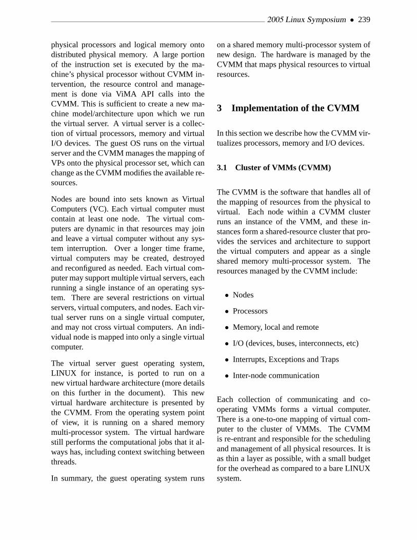
2005 Linux Symposium • 239
physical processors and logical memory ontodistributed physical memory. A large portionof the instruction set is executed by the ma-chine’s physical processor without CVMM in-tervention, the resource control and manage-ment is done via ViMA API calls into theCVMM. This is sufficient to create a new ma-chine model/architecture upon which we runthe virtual server. A virtual server is a collec-tion of virtual processors, memory and virtualI/O devices. The guest OS runs on the virtualserver and the CVMM manages the mapping ofVPs onto the physical processor set, which canchange as the CVMM modifies the available re-sources.
Nodes are bound into sets known as VirtualComputers (VC). Each virtual computer mustcontain at least one node. The virtual com-puters are dynamic in that resources may joinand leave a virtual computer without any sys-tem interruption. Over a longer time frame,virtual computers may be created, destroyedand reconfigured as needed. Each virtual com-puter may support multiple virtual servers, eachrunning a single instance of an operating sys-tem. There are several restrictions on virtualservers, virtual computers, and nodes. Each vir-tual server runs on a single virtual computer,and may not cross virtual computers. An indi-vidual node is mapped into only a single virtualcomputer.
The virtual server guest operating system,LINUX for instance, is ported to run on anew virtual hardware architecture (more detailson this further in the document). This newvirtual hardware architecture is presented bythe CVMM. From the operating system pointof view, it is running on a shared memorymulti-processor system. The virtual hardwarestill performs the computational jobs that it al-ways has, including context switching betweenthreads.
In summary, the guest operating system runs
on a shared memory multi-processor system ofnew design. The hardware is managed by theCVMM that maps physical resources to virtualresources.
3 Implementation of the CVMM
In this section we describe how the CVMM vir-tualizes processors, memory and I/O devices.
3.1 Cluster of VMMs (CVMM)
The CVMM is the software that handles all ofthe mapping of resources from the physical tovirtual. Each node within a CVMM clusterruns an instance of the VMM, and these in-stances form a shared-resource cluster that pro-vides the services and architecture to supportthe virtual computers and appear as a singleshared memory multi-processor system. Theresources managed by the CVMM include:
• Nodes
• Processors
• Memory, local and remote
• I/O (devices, buses, interconnects, etc)
• Interrupts, Exceptions and Traps
• Inter-node communication
Each collection of communicating and co-operating VMMs forms a virtual computer.There is a one-to-one mapping of virtual com-puter to the cluster of VMMs. The CVMMis re-entrant and responsible for the schedulingand management of all physical resources. It isas thin a layer as possible, with a small budgetfor the overhead as compared to a bare LINUXsystem.

240 • LINUX R© Virtualization on Virtual IronTM VFe
Figure 2: Virtual Iron paravirtualization (IntelIA-32).
3.2 Virtualizing Processors
Each of the physical processors is directly man-aged by the CVMM and only by the CVMM.A physical processor is assigned to a single vir-tual computer, and may be used for any of thevirtual servers that run on that virtual computer.As we stated before, the method of virtualizingthe processors that is used in the Virtual IronVFe isparavirtualization. The diagram inFig-ure 2 illustrates our implementation of the par-avirtualization concept on the IA-32 platform:
In this scheme, the vast majority of the vir-tual processor’s instructions are executed by thereal processor without any intervention fromthe CVMM, and certain privileged instructionsused by the guest OS are rewritten to use theViMA APIs. As with other VMMs, we takeadvantage of underlying memory protection inthe Intel architecture. The CVMM runs in theprivilege ring-0, the guest OS runs in ring-1 andthe user applications run in ring-3. The CVMMis the only entity that runs in ring-0 of the pro-cessor and it is responsible for managing all op-erations of the processor, such as booting, ini-tialization, memory, exceptions, and so forth.
Virtual processors are mapped to physical pro-
cessors by the CVMM. There are a number ofrules that are followed in performing this map-ping:
• Virtual processors are scheduled concur-rently, and there are never more virtualprocessors than physical processors withina single virtual server.
• The CVMM maintains the mapping of vir-tual processors to physical processors.
• Physical processors may belong to a vir-tual computer, but are not required to beused or be active for any particular virtualserver.
These rules lead to a number of conclusions.First, any number of physical processors maybe assigned to a virtual computer. However, atany given moment, the number of active phys-ical processors is the same as the number ofvirtual processors in the current virtual server.Moreover, the number of active virtual proces-sors in a virtual server is less than or equalto the number of physical processors available.For instance, if a node is removed from a vir-tual computer, it may be necessary for a vir-tual server on that virtual computer to reducethe number of active virtual processors.
3.3 Interrupts, Traps and Exceptions
The CVMM is set-up to handle all inter-rupts, traps and exceptions. Synchronous trapsand exceptions are mapped directly back intothe running virtual processor. Asynchronousevents, such as interrupts, have additional logicsuch that they can be mapped back to the ap-propriate virtual server and virtual processor.
2005 Linux Symposium • 241
3.4 Virtualizing Memory
Memory, like processors, is a resource that isshared across a virtual computer and used bythe virtual servers. Shared memory imple-mented within a distributed system naturallyresults in non-uniform memory access times.The CVMM is responsible for memory man-agement, initialization, allocation and sharing.Virtual servers are not allowed direct access tothe page tables. However, these tables needto be managed to accommodate a number ofgoals:
• First, they need to be able to specificallylocate an individual page which may re-side in any one of the physical nodes
• They must be able to allow several levelsof cost. That is, the virtual server shouldbe able to manipulate page tables at thelowest possible cost in most instances toavoid round-trips through the CVMM.
• Isolation is a requirement. No virtualserver should be able to affect any othervirtual server. If several virtual serversare running on the same virtual computer,then any failures, either deliberate or acci-dental, should not impact the other virtualservers.
The illusion of a shared memory multi-processor system is maintained in the VirtualIron architecture by the sharing of the memoryresident in all of the nodes in a virtual com-puter. As various processors need access topages of memory, that memory needs to be res-ident and available for local access. As pro-cesses, or the kernel, require access to pages,the CVMM is responsible for insuring the rel-evant pages are accessible. This may involvemoving pages or differences between the mod-ified pages.
3.5 Virtualizing I/O Devices
Just as with the other resources, the CVMMmanages all I/O devices. No direct access bya virtual server is allowed to any I/O device,control register or interrupt. The ViMA pro-vides APIs to access the I/O devices. The vir-tual server uses these APIs to access and con-trol all I/O devices.
All I/O for the virtual computer is done viainterfaces and mechanisms that can be sharedacross all the nodes. This requires a set ofdrivers within the CVMM that accommodatethis, as well as a proper abstraction at the levelof a virtual server to access the Fibre Channeland Ethernet.
With the previous comments in mind, the jobof the CVMM is to present a virtualized I/O in-terface between the virtual computer physicalI/O devices and the virtual servers. This inter-face provides for both sharing and isolation be-tween virtual servers. It follows the same styleand paradigm of the other resources managedby the CVMM.
4 LINUX Kernel Port
This section describes our port of the LINUX2.6 kernel to the IA-32 implementation of theVirtual Iron Machine Architecture. It doesn’tspecify the architecture in detail, but rather de-scribes our general approach and important pit-falls and optimizations, many of which can ap-ply to other architectures real and virtual. Firstwe’ll look at the essential porting work requiredto make the kernel run correctly, then at themore substantial work to make it run well, andfinally at the (substantial) work required to sup-port dynamic reconfiguration changes.

242 • LINUX R© Virtualization on Virtual IronTM VFe
4.1 Basic Port
We started with an early 2.6 LINUX kernel, de-riving our architecture port from the i386 codebase. The current release as of this writingis based on the 2.6.9 LINUX kernel. As theburden of maintaining a derived architecture issubstantial, we are naturally interested in co-operating with various recent efforts to refac-tor and generalize support for derived (e.g.,x86_64) and virtualized (e.g., Xen) architec-tures.
The ViMA interface is mostly implemented viasoft interrupts (like syscalls), though memory-mapped interfaces are used in some specialcases where performance is crucial. Thedata structures used to communicate with theCVMM (e.g., descriptor tables, page tables) areclose, if not identical, to their IA-32 equiva-lents.
The basic port required only a single modifica-tion to common code, to allow architectures tooverridealloc_pgd()and free_pgd(). Thoughas we’ll see later, optimizing performance andadding more dynamic reconfiguration supportrequired more common code modifications.
The virtual server configuration is always avail-able to the LINUX kernel. As mentioned ear-lier, it exposes the topology of the underlyinghardware: a cluster ofnodes, each providingmemory and (optionally) CPUs. The configura-tion also describes the virtual devices availableto the server. Reading virtual server configu-ration replaces the usual boot-time BIOS andACPI table parsing and PCI bus scanning.
4.2 Memory Management
The following terms are used throughout thissection to describe interactions between the
Page Type MeaningPhysical page A local memory instance
(copy) of a ViMA logicalpage. The page contentsare of interest to the own-ing virtual server.
Physical pageframe
A local memory con-tainer, denoted by aspecific physical address,managed by the CVMM.
Logical page A virtual server page,the contents of which aremanaged by the guest op-erating system.The phys-ical location of a logicalpage is not fixed, nor evenexposed to the guest oper-ating system.
Logical pageframe
A logical memory con-tainer, denoted by a spe-cific logical address, man-aged by the guest operat-ing system.
Replicated page A logical page may bereplicated on multiplenodes as long as thecontents are quaranteedto be identical. Writing toa replicated logical pagewill invalidate all othercopies of the page.
Table 1: Linux Memory Management in VirtualIron VFe
LINUX guest operating system and the VirtualIron CVMM.
Isolating a virtual server from the CVMM andother virtual servers sharing the same hardwarerequires that memory management be carefullycontrolled by the CVMM. Virtual servers can-not see or modify each other’s memory underany circumstances. Even the contents of freedor “borrowed” physical pages are never visibleto any other virtual server.

2005 Linux Symposium • 243
Accomplishing this isolation requires explicitmechanisms within the CVMM. For example,CPU control register cr3 points to the top-levelpage directory used by the CPU’s paging unit.A malicious guest OS kernel could try to pointthis to a fake page directory structure map-ping pages belonging to other virtual serversinto its own virtual address space. To preventthis,only the CVMM can create and modify thepage directories / tables used by the hardware,and it must ensure that cr3 is set only to a top-level page directory that it created for the ap-propriate virtual server.
On the other hand, the performance of memorymanagement is also of crucial importance. Tak-ing a performance hit on every memory accessis not acceptable; thecommon case(in whichthe desired logical page is in local memory,mapped, and accessible)suffers no virtualiza-tion overhead.
The MMU interface under ViMA 32-bit archi-tecture is mostly the same as that of the IA-32in PAE mode, with three-level page tables of64-bit entries. A few differences exist, mostlythat ours map 32-bit virtual addresses to 40-bit logical addresses, and that we use softwaredirty and access bits since these aren’t set bythe CVMM.
The page tables themselves live in logicalmemory, which can be distributed around thesystem. To reduce possibly-remote page tableaccesses during page faults, the CVMM im-plements fairly aggressive software TLB. Un-like the x86 TLB, the CVMM supports Ad-dress Space Number tags, used to differenti-ate and allow selective flushing of translationsfrom different page tables. The CVMM TLB isnaturally kept coherent within a node, so a lazyflushing scheme is particularly useful since (aswe’ll see later) we try to minimize cross-nodeprocess migration.
4.3 Virtual Address Space
The standard 32-bit LINUX kernel reserves thelast quarter (gigabyte) of virtual addresses forits own purposes. The bottom three quarters ofvirtual addresses makes up the standard process(user-mode) address space.
Much efficiency is to be gained by having theCVMM share its virtual address space with theguest OS. So the LINUX kernel is mapped intothe top of the CVMM’s user-space, somewhatreducing the virtual address space available toLINUX users. The amount of virtual addressspace required by the CVMM depends on avariety of factors, including requirements ofdrivers for the real hardware underneath. Thisoverhead becomes negligible on 64-bit archi-tectures.
4.4 Booting
As discussed earlier, a guest OS kernel runsat privilege level 1 in the IA-32 ViMA. Wefirst replaced the privileged instructions in thearch code by syscalls or other communicationwith the CVMM. Kernel execution starts whenthe CVMM is told to start a virtual server andpointed at the kernel. The boot virtual proces-sor then starts executing the boot code. VPs arealways running in protected mode with pagingenabled, initially using anull page table sig-nifying direct (logical = virtual) mapping. Sothe early boot code is fairly trivial, just estab-lishing a stack pointer and setting up the ini-tial kernel page tables before dispatching to Ccode. Boot code for secondary CPUs is evenmore trivial since there are no page tables tobuild.
4.5 Interrupts and Exceptions
The LINUX kernel registers handlers for inter-rupts with the CVMM via a virtualized Inter-

244 • LINUX R© Virtualization on Virtual IronTM VFe
rupt Descriptor Table. Likewise, the CVMMprovides a virtualized mechanism for maskingand unmasking interrupts. Any information(e.g., cr2, etc.) necessary for processing an in-terrupt or exception that is normally readableonly at privilege level 0 is made available tothe handler running at level 1. Interrupts actu-ally originating in hardware are delivered to theCVMM, which processes them and routes themwhen necessary to the appropriate virtual serverinterrupt handlers. Particular care is taken toprovide a “fast path” for exceptions (like pagefaults) and interrupts generated and handled lo-cally.
Particularly when sharing a physical proces-sor among several virtual servers, interruptscan arrive when a virtual server is not cur-rently running. In this case, the interrupt(s) arepended , possibly coalescing several for thesame device into a single interrupt. Becausethe CVMMs handle all actual device communi-cation, LINUX is not subject to the usual hard-ware constraints requiring immediate process-ing of device interrupts, so such coalescing isnot dangerous, provided that the interrupt han-dlers realize the coalescing can happen and actaccordingly.
4.6 I/O
The ViMA I/O interface is designed to beflexible and extensible enough to support newclasses of devices as they come along. Theinterface is not trying to present somethingthat looks likereal hardware , but ratherhigher-level generic conduits between the guestOS and the CVMM. That is, the ViMA itselfhas no understanding of I/O operation seman-tics; it merely passes data and control signalsbetween the guest operating system and theCVMM. It supports the following general ca-pabilities:
• device discovery
• device configuration
• initiation of (typically asynchronous) I/Ooperations
• completion of asynchronous I/O opera-tions
Because I/O performance is extremely impor-tant, data is presented in large chunks to mit-igate the overhead of going through an extralayer. The only currently supported I/O devicesare Console (VCON), Ethernet (VNIC), and Fi-bre Channel storage (VHBA). We have imple-mented thebottom layer of three new de-vice drivers to talk to the ViMA, while the in-terface from above remains the same for driversin the same class. Sometimes the interfacefrom above is used directly by applications, andsometimes it is used by higher-level drivers. Ineither case, the upper levels work “as is.”
In almost all cases, completion interrupts aredelivered on the CPU that initiated the opera-tion. But since CPUs (and whole nodes) maybe dynamically removed, LINUX can steer out-standing completion interrupts elsewhere whennecessary.
4.7 Process and Thread Scheduling
The CVMM runs one task per virtual proces-sor, corresponding to its main thread of control.The LINUX kernel further divides these tasksto run LINUX processes and threads, startingwith the vanilla SMP scheduler. This approachis more like the one taken by CoVirt[King-03]and VMWare Workstation[Sugerman-01], asopposed to having the underlying CVMMschedule individual LINUX processes as donein L4[Liedtke-95] . This is consistent with our

2005 Linux Symposium • 245
general approach of exposing as much informa-tion and control as possible (without compro-mising virtual server isolation) to the guest OS,which we assume can make better decisions be-cause it knows the high-level context. So, otherthan porting the architecture-specific context-switching code, no modifications were neces-sary to use the LINUX scheduler.
4.8 Timekeeping
Timekeeping is somewhat tricky on such aloosely coupled system. Because thejiffiesvariable is used all over the place, updatingthe global value on every clock interrupt gener-ates prohibitively expensive cross-node mem-ory traffic. On the other hand, LINUX ex-pects jiffies to progress uniformly. Normallyjiffies is aliased tojiffies_32, the lower 32 bitsof the full 64-bit jiffies_64counter. Throughsome linker magic, we makejiffies_32 pointinto a special per-node page (a page whose log-ical address maps to a different physical pageon each node), so each node maintains its ownjiffies_32. The globaljiffies_64is still updatedevery tick, which is no longer a problem sincemost readers are looking atjiffies_32. Thelocal jiffies_32values are adjusted (incremen-tally, without going backwards) periodically tokeep them in sync with the global value.
4.9 Crucial Optimizations
The work described in the previous sections isadequate to boot and run LINUX, but the re-sulting performance is hardly adequate for allbut the most contrived benchmarks. The tough-est challenges lie in minimizing remote mem-ory access (and communication in general).
Because the design space of potentially usefuloptimizations is huge, we strive to focus our op-timization efforts by guiding them with perfor-mance data. One of the advantages of a virtual
machine is ease of instrumentation. To this end,our CVMM has a large amount of (optional)code devoted to gathering and reporting per-formance data, and in particular for gatheringinformation about cross-node memory activity.Almost all of the optimizations described herewere driven by observations from this perfor-mance data gathered while running our initialtarget applications.
4.9.1 Logical Frame Management andNUMA
When LINUX runs on non-virtualized hard-ware, page frames are identified by physicaladdress, but when it runs on the ViMA, pageframes are described bylogical address.Though logical page frames are analogous tophysical page frames, logical page frames havesomewhat different properties:
• Logical page frames are dynamicallymapped to physical page frames by theCVMM in response to page faults gener-ated while the guest OS runs
• Logical page frames consume physicalpage frames only when mapped and ref-erenced by the guest OS.
• The logical page frames reserved by theCVMM are independent of the physicalpage frames reserved for PC-compatiblehardware and BIOS.
Suppose we have a system consisting of fourdual-processor SMP nodes. Such a systemcan be viewed either as a “flat” eight-processorSMP machine or (viaCONFIG_NUMA) asa two-level hierarchy of four two-processornodes (i.e., the same as the underlying hard-ware). While the former view works correctly,

246 • LINUX R© Virtualization on Virtual IronTM VFe
hiding the real topology has serious perfor-mance consequences. The NUMA kernel as-sumes each node manages its own range ofphysical pages. Though pages can be used any-where in the system, the NUMA kernel tries toavoid frequent accesses to remote data.
In some sense, the ViMA can be treated is avirtual cache coherent NUMA (ccNUMA) ma-chine, in that access to memory is certainlynon-uniform.
By artificially associating contiguous logicalpage ranges with nodes, we can make ourvirtual server look like a ccNUMA machine.We realized much better performance by treat-ing the virtual machine as a ccNUMA ma-chine reflecting the underlying physical hard-ware. In particular the distribution of mem-ory into more zones alleviates contention forthe zone lock and lru_lock. Furthermore, theoptimizations that benefit most ccNUMA ma-chines benefit ours. And the converse is trueas well. We’re currently cooperating with otherNUMA LINUX developers on some new op-timizations that should benefit all large cc-NUMA machines.
For various reasons, the most important be-ing some limitations of memory removal sup-port, we currently have a fictitious CPU-lessnode 0 that manages all of low memory (theDMA and NORMAL zones). So HIGHMEMis divvied up between the actual nodes in pro-portion to their relative logical memory size.
4.9.2 Page Cache Replication
To avoid the sharing of page metadata by nodesusing replicas of read-only page cache pages,we have implemented a NUMA optimizationto replicate such pages on-demand from node-local memory. This improves benchmarks thatdo a lot of exec’ing substantially.
4.9.3 Node-Aware Batch Page Updates
Both fork() andexit()update page metadata forlarge numbers of pages. As currently coded,they update the metadata in the order the pagesare walked. We see measurable improvementsby splitting this into multiple passes, each up-dating the metadata only for pages on a specificnode.
4.9.4 Spinlock Implementation
The i386 spinlock implementation also turnedout to be problematic, as we expected. Theatomic operation used to try to acquire a spin-lock requires write access to the page. Thisworks fine if the lock isn’t under contention,particularly if the page is local. But if some-one else is also vying for the lock, spinningas fast as possible trying to access remote dataand causing poor use of resources. We con-tinue to experiment with different spinlock im-plementations (which often change in responseto changes in the memory access characteris-tics of the underlying CVMM). Currently wealways try to get the lock in the usual way first.If that fails, we fall into our ownspinlock_wait() that does a combination of “remote”reads and yielding to the CVMM before tryingthe atomic operation again. This avoids over-loading the CVMM to the point of restrictinguseful work from being done.
4.9.5 Cross-Node Scheduling
The multi-level scheduling domains intro-duced in 2.6 LINUX kernel match very nicelywith a hierarchical system like Virtual IronVFe. However, we found that the cross-nodescheduling decisions in an environment likethis are based on much different factors than theschedulers for more tightly-coupled domains.

2005 Linux Symposium • 247
Moreover, because cross-node migration of arunning program is relatively expensive, wewant to keep such migrations to a minimum. Sothe cross-node scheduler can runmuchless of-ten than the other domain schedulers, so it be-comes permissible to take a little longer mak-ing the scheduling decision and take more fac-tors into account. In particular, task and nodememory usage are crucial—much more impor-tant than CPU load. So we have implemented adifferent algorithm for the cross-node schedul-ing domain.
The cross-node scheduling algorithm repre-sents node load (and a task’s contributionto it) with a 3-d vector whose compo-nents represent CPU, memory, and I/O us-age. Loads are compared by taking the vectornorm[Bubendorfer-96]. While we’re still ex-perimenting heavily with this scheduler, a fewconclusions are clear. First, memory mattersfar more than CPU or I/O loads in a system likeours. Hence we weight the memory componentof the load vector more heavily than the othertwo. It’s also important to be smart about howtasks share memory.
Scheduling and logical memory management istightly intertwined. Using the default NUMAmemory allocation, processes try to get mem-ory from the node on which they’re runningwhen they allocate. We’d prefer that processesuse such local pages so they don’t fight withother processes or the node’s swap daemonwhen memory pressure rises. This implies thatwe would rather avoid moving a process af-ter it allocates its memory. Redistributing aprocess to another node atexec()time makesa lot of sense, since the process will have itssmallest footprint at that point. Processes oftenshare data with other processes in the same pro-cess group. So we’ve modifiedsched_exec()toconsider migrating an exec’ing process to an-other node only if it’s a process group leader(and with even more incentive—via a lower im-
balance threshold—for session group leaders).Furthermore, whensched_exec()does considermigrating to another node, it looks at the 3-d load vectors described earlier. This policyhas been particularly good for distributing thememory load around the nodes.
4.10 Dynamic Reconfiguration Support(Hotplug Everything)
When resources (CPU or memory) are added orremoved from a the cluster, the CVMM noti-fies the guest OS via a special “message” inter-rupt also used for a few other messages (“shut-down,” “reboot,” etc.). LINUX processes theinterrupt by waking a message handler thread,which then reads the new virtual server config-uration and starts taking the steps necessary torealize it. Configuration changes occur in twophases. During the first phase, all resourcesbeing removed are going away. LINUX ac-knowledges the change when it has reducedits resource usage accordingly. The resourcesare, of course, not removed until LINUX ac-knowledges. During the second phase, all re-sources being added are added (this time be-fore LINUX acknowledges), so LINUX simplyadds the new resources and acknowledges thatphase. This implies certain constraints on con-figuration changes. For example, there must beat least one VP shared between the old and newconfigurations.
4.10.1 CPU and Device Hotplug
Adding and removing CPUs and devices re-quired some porting to our methods of start-ing and stopping CPUs and devices, but for themost part this is much easier with idealized vir-tual hardware than with the real thing.

248 • LINUX R© Virtualization on Virtual IronTM VFe
4.10.2 Node Hotplug
Adding and removing whole nodes was a littlemore problematic as most iterations over nodesin the system assumes online nodes are con-tiguous going from 0 tonumnodes-1. Node re-moval can leave a “hole” which invalidates thisassumption. The CPUs associated with a nodeare made “physically present” or absent as thenode is added or removed.
4.10.3 Memory Hotplug
Memory also comes with a node (thoughnodes’ logical memory can be increased or de-creased without adding or removing nodes),and must be made hotpluggable. Unfortunatelyour efforts in this area proceeded independentlyfor quite a while until we encountered thememory hotplug effort being pursued by othermembers of LINUX development community.We’ve decided to combine our efforts and planon integrating with the new code once we moveforward from 2.6.9 code base. Adding memoryisn’t terribly hard, though some more synchro-nization is needed. At the global level, a mem-ory hotplug semaphore, analogous to the CPUhotplug semaphore, was introduced. Carefulordering of the updates to the zones allowsmost of the existing references to zone memoryinfo to continue to work without locking.
Removing memory is much more difficult. Ourexisting approach removes only high memory,and does so by harnessing the swap daemon. Anew page bit,PG_capture, is introduced (nameborrowed from the other memory hotplug ef-fort) to mark pages that are destined for re-moval. Such pages are swapped out more ag-gressively so that they may be reclaimed assoon as possible. Freed pages marked for cap-ture are taken off the free lists (and out of theper-cpu pagesets), zeroed (so the CVMM can
forget them), then counted as removed. Duringmemory removal, the swap daemons on nodeslosing memory are woken often to attempt toreclaim pages marked for capture. In addi-tion, we try reclaiming targeted pages from theshrinking zones’ active lists.
This approach works well on a mostly idle (orat least suspended) machine, but has a num-ber of weaknesses, particularly when the mem-ory in question is being actively used. Directpage migration (bypassing swap) would be anobvious performance improvement. There arepages that can’t be removed for various rea-sons. For example, pages locked into memoryvia mlock()can’t be written to disk for securityreasons.
But because our logical pages aren’t actuallytied to nodes (but just artificially assigned tothem for management purposes), we can tol-erate a substantial number of “unremovable”pages. A node that has been removed, but stillhas some “unremovable” pages is known as a“zombie” node. No new pages are allocatedfrom the node, but existing pages and zone dataare still valid. We’ll continue to try and re-claim the outstanding pages via the node’s swapdaemon (now running on a different node, ofcourse). If another node is added in its placebefore all pages are removed, the new node cansubsume the “unremovable” pages and it be-comes a normal page again. In addition, it isalso possible to exchange existing free pagesfor “unremovable” pages to reclaim space forreplicas. While this scheme is currently farfrom perfect or universal, it works predictablyin enough circumstances to be useful.
5 Conclusion
In this paper we have presented a ClusteredVirtual Machine Monitor that virtualizes a set

2005 Linux Symposium • 249
of distributed resources into a shared mem-ory multi-processor machine. We have portedLINUX Operating System onto this platformand it has shown to be an excellent platformfor deploying a wide variety of general purposeapplications.
6 Acknoweledgement
We would like to thank all the members of theVirtual Iron Software team without whom Vir-tual Iron VFe and this paper would not be pos-sible. Their contribution is gratefully acknowl-edged.
Virtual Iron and Virtual Iron VFe are trademarks ofVirtual Iron Software, Inc. LINUXR© is a registeredtrademark of Linus Torvalds. XEON is a trademarkof Intel Corp. All other other marks and names men-tioned in this paper may be trademarks of their re-spective companies.
References
[Pfister-98] Gregory F. Pfister.In Search ofClusters, Second Edition, Prentice HallPTR, pp. 358–369, 1998.
[Goldberg-74] R.P. Goldberg. Survey of Vir-tual Machines Research.Computer, pp.34–45, June 1974.
[Robin-00] J.S. Robin and C.E. Irvine. Analy-sis of the Intel Pentium’s Ability to Sup-port a Secure Virtual Machine Monitor. InProceedings of the 9th USENIX SecuritySymposium, pp. 3–4, August 20, 2000.
[Goldberg-72] R.P. Goldberg.ArchitecturalPrinciples for Virtual Computer Systems.Ph.D. Thesis, Harvard University, Cam-bridge, MA, 1972.
[Whitaker-00] A. Whitaker, M. Shaw, and S.Gribble. Scale and Performance in the De-nali Isolation Kernel. InACM SIGOPSOperating System Rev., vol. 36, no SI, pp.195–209, Winter 2000.
[King-03] S. King, G. Dunlap, and P. ChenOperating System Support for VirtualMachines. InProceedings of the 2003USENIX Technical Conference, 2003.
[Sugerman-01] J. Sugerman, G. Venkitacha-lam, and B. Lim. Virtualizing I/O Deviceson VMWare Workstation’s Hosted Vir-tual Machine Monitor. InProceedings ofthe 2001 USENIX Technical Conference,June, 2001.
[Liedtke-95] Dr. Jochen Liedtke. On Micro-Kernel Construction. InProceedings ofthe 15th ACM Symposium on OperatingSystems Principles, December, 1995.
[Bubendorfer-96] K.P. Bubendorfer.ResourceBased Policies for Load Distribution.Masters Thesis, Victoria University ofWellington, Wellington, New Zealand,1996.

250 • LINUX R© Virtualization on Virtual IronTM VFe

Clusterproc: Linux Kernel Support for ClusterwideProcess Management
Bruce J. WalkerHewlett-Packard
Laura RamirezHewlett-Packard
John L. ByrneHewlett-Packard
Abstract
There are several kernel-based clusterwide pro-cess management implementations availabletoday, providing different semantics and ca-pabilities (OpenSSI, openMosix, bproc, Ker-righed, etc.). We present a set of hooks to allowvarious installable kernel module implementa-tions, with a high degree of flexibility and vir-tually no performance impact. Optional capa-bilities that can be implemented via the hooksinclude: clusterwide unique pids, single init,heterogeneity, transparent visibility and accessto any process from any node, ability to dis-tribute processes at exec or fork or thru mi-gration, file inheritance and full controlling ter-minal semantics, node failure cleanup, cluster-wide /proc/<pid> , checkpoint/restart andscale to thousands of nodes. In addition, wedescribe an OpenSSI-inspired implementationusing the hooks and providing all the featuresdescribed above.
1 Background
Kernel based cluster process management(CPM) has been around for more than 20years, with versions on Unix by Locus[1] andMosix[2]. The Locus system was a general pur-pose Single System Image (SSI) cluster, with a
single root filesystem and a single namespacefor processes, files, networking and interpro-cess communication objects. It provided highavailability as well as a simple managementparadigm and load balancing of processes.Mosix focused on process load balancing. Theconcepts of Locus have moved to Linux via theOpenSSI[3] open source project. Mosix hasmoved to Linux via the openmosix[4] project.
OpenSSI and Mosix were not initially tar-geted at large scale parallel programming clus-ters (eg. those using MPI). The BProc[5]CPM project has targeted that environment tospeed up job launch and simplify process man-agement and cluster management. More re-cent efforts by Kerrighed[6] and USI[7] (nowCassat[8]) were also targeted at HPC environ-ments, although Cassat is now interested incommercial computing.
These 5 CPM implementations have somewhatdifferent cluster models (different forms of SSI)and thus fairly different implementations, inpart driven by the environment they were orig-inally developed for. The “Introduction to SSI”paper[10] details some of the differences. Herewe outline some of the characteristics relevantto CPM. Mosix started as a workstation tech-nology that allowed a user on one workstationto utilize cpu and memory from another work-station by moving running processes (processmigration) to the other workstation. The mi-
• 251 •

252 • Clusterproc: Linux Kernel Support for Clusterwide Process Management
grated processes had to see the OS view of theoriginal workstation (home node) since therewas no enforced common view of resourcessuch as processes, filesystem, ipc objects, bina-ries, etc. To accomplish the home-node view,most system calls had to be executed back onthe home node—the process was effectivelysplit, with the kernel part on the home nodeand the application part elsewhere. What thismeans to process ids is that home nodes gener-ate ids which are not clusterwide unique. Mi-grated processes retain their home node pid ina private data structure but are assigned a lo-cal pid by the current host node (to avoid pidconflicts). The BProc model is similar exceptthere is a single home node (master node) thatall processes are created on. These ids are thusclusterwide unique and a local id is not neededon the host node.
The model in OpenSSI, Kerrighed and Cassat isdifferent. Processes can be created on any nodeand are given a single clusterwide pid whenthey are created. They retain that pid no matterwhere they execute. Also, the node the processwas created on does not retain part of the pro-cess. What this means to the CPM implementa-tion is that actions to be done against processesare done where the process is currently execut-ing and not on the creation or home node.
There are many other differences among theCPM implementations. For example, OpenSSIhas a single, highly available init process whilemost/all other implementations do not. Addi-tionally, BProc does not retain a controlling ter-minal (or any other open files) when processesmove, while other implementations do. Someimplementations, like OpenSSI, support clus-terwide ptrace, while others do not.
With some of these differences in mind, wenext look at the goals for a set of CPM hooksthat would satisfy most of the CPM implemen-tations.
2 Goals and Requirements for theClusterproc Hooks
The general goals for the hooks are to enablea variety of CPM implementations while beingnon-invasive enough to be accepted in the basekernel. First we look at the base kernel require-ments and then some of the functional require-ments.
Changes to the base kernel should retain the ar-chitectural cleanliness and not affect the per-formance. Base locking should be used andcopies of base routines should be avoided. Theclusterproc implementations should be instal-lable modules. It should be possible to buildthe kernel with the hooks disabled and that ver-sion should have no impact on performance. Ifthe hooks are enabled, the module should beoptional. Without the module loaded, perfor-mance impact should be negligible. With themodule loaded, one would have a one nodecluster and performance will depend on theCPM implementation.
The hooks should enable at least the followingfunctionality:
• optionally have a per process data struc-ture maintained by the CPM module;
• allowing for the CPM module to allocateclusterwide process ids;
• support for distributed process rela-tionships including parent/child, processgroup and session; optional support fordistributed thread groups and ptrace par-ent;
• optional ability to move running pro-cesses from one node to another either atexec/fork time or at somewhat arbitrarypoints in their execution;
2005 Linux Symposium • 253
• optional ability to transparently check-point/restart processes, process groups andthread groups;
• optional ability to have process continue toexecute even if the node they were createdon leaves the cluster;
• optional ability to retain relationships ofremaining processes, no matter whichnodes may have crashed;
• optional ability to have full controlling ter-minal semantics for processes running re-motely from their controlling terminal de-vice;
• full, but optional/proc/<pid> capabil-ity for all processes from all nodes;
• capability to support either an “init” pro-cess per node or a single init for the entirecluster;
• capability to function within a shared rootenvironment or in an environment with aroot filesystem per node;
• capability to be an installable modulethat can be installed either from theramdisk/initramfs or shortly thereafter;
• support for clusters of up to 64000 nodes,with optional code to support larger;
In the next section we detail a set of hooks de-signed to meet the above set of goals and re-quirements. Following that is the design of theOpenSSI 3.0, as adapted to the proposed hooks.
3 Proposed Hook Architecture,Hook Categories and Hooks
To enable the optional inclusion of clusterwideprocess management (referred also as “clus-terproc” or CPM) capability, very small data
structure additions and a set of entry pointsare proposed. The data structure additions area pointer in the task structure (CPM imple-mentations could then allocate a per processstructure that this pointer points to), and 2 flagbits. The infrastructure for the hooks is pat-terned after the security hooks, although not ex-actly the same. IfCONFIG_CLUSTERPROCisnot set, the hooks are turned into inline func-tions that are either empty or return the de-fault value. WithCONFIG_CLUSTERPROCde-fined, the hook functions call clusterproc ops ifthey are defined, otherwise returning the defaultvalue. The ops can be replaced, and the clus-terproc install-able module will replace the opswith routines to provide the particular CPM im-plementation. The clusterproc module wouldbe loaded early in boot. All the code to sup-port the clusterwide process model would beunder GPL. To enable the module some addi-tional symbols will have to exported to GPLmodules.
The proposed hooks are grouped into cat-egories below. Each CPM implementationcan provide op functions for all or someof the hooks in each category. For eachcategory we list the relevant hook functionsin pseudo-C. The names would actually beclusterproc_xxx but to fit here we leaveout the clustproc_ part. The parametersare abreviated. For each category, we de-scribe the general purpose of the hooks inthat category and how the hooks could beused in different CPM implementations. Thecategories are: Init and Reaper; Allocation/Free; Update Parent; Process lock/unlock;Exit/Wait/Reap; Signalling; Priority and Capa-bility; Setpgid/Setsid; Ptrace; Controlling Ter-minal; and Process movement;
3.1 Init and Reaper
void single_init();
254 • Clusterproc: Linux Kernel Support for Clusterwide Process Management
void child_reaper(*pid);
One of the goals was to allow the cluster torun with a single init process for the cluster.The single_init hook in init/main.c ,init() can be used in a couple of ways. First,if there is to be a single init, this routine canspawn a “reaper” process that will locally reapthe orphan processes that init normally reaps.On the node that is going to have the init, theroutine returns to allow init to be exec’d. Onother nodes it can exit so there is no process1 on those nodes. The other hook in this cat-egory ischild_reaper , which is in timer.c,sys_getppid() . It returns 1 if the process’sparent was thechild_reaper process. Nei-ther of these hooks would be used in those CPMimplementations that have an init process pernode.
3.2 Allocation/ Free
int fork_alloc(*tsk);void exit_dealloc(*tsk);int pid_alloc(pid);int local_pid(pid);void strip_pid(*pid);
There are 5 hooks functions in this category.First isfork_alloc , which is called incopy_
process() in fork.c . This routine is calledto allow the CPM to allocate a private datastructure pointed to byclusterproc pointerwhich is added to the task structure. Free-ing that structure is done via the hookexit_
dealloc() which is called in release_
task() in exit.c and under error condi-tions in copy_process() in fork.c Theexit_dealloc routine can also be used to doremote notifications necessary for pgrp and ses-sion management. All CPM implementationswill probably use these hooks. The other 3hooks deal with pid allocation and freeing and
are only used in those implementations present-ing a clusterwide single pid space. Thepid_
alloc hook is called inalloc_pidmap() inpid.c . It takes a locally unique pid and re-turns a clusterwide unique pid, possibly by en-coding a node number in some of the high orderbits. Thelocal_pid andstrip_pid hooksare in free_pidmap() , also in pid.c Thelocal_pid hook returns 1 if this pid was gen-erated on this node and the process id is nolonger needed clusterwide. Otherwise return0. Thestrip_pid hook is called to undo theeffects ofpid_alloc so the base routines oneach node can manage their part of the cluster-wide pid space.
3.3 Update parent
int update_parent(*ptsk,*ctsk,flag,sig,siginfo);
Update_parent is a very general hook calledin several places. It is used by a child pro-cess to notify a parent process if the parentprocess is executing remotely. Inptrace.c , it is called in __ptrace_unlink() and__ptrace_link() . In the arch version ofptrace.c it is called insys_ptrace() . Inexit.c it is called inreparent_to_init()
and infork.c , copy_process() , it is calledin the CLONE_PARENTcase. Although not allCPM implementations will support distributedptrace orCLONE_PARENT, support for some ofthe instances of this hook will probably be ineach CPM implementation.
3.4 Process lock/unlock
void proc_lock(*tsk,base_lock);void proc_unlock(*tsk,base_lock);

2005 Linux Symposium • 255
Theproc_lock andproc_unlock hooks al-low the CPM implementation to either use thebasetsk->proc_lock (default) or to intro-duce a sleep lock in their private process datastructure. In some implementations, a sleeplock is needed because remote operations maybe executed while this lock is held. In addition,calls to proc_lock and proc_unlock areadded inexit_notify() , in exit.c , be-causeexit_notify() may not be atomic andmay need to be interlocked withsetpgid()
and with process movement (the locking callsfor setpgid and process movement would be inthe CPM implementation.
3.5 Exit/Wait/Reap
int rmt_reparent_children(*tsk);int is_orphan_pgrp(pgrp);void rmt_orphan_pgrp(newpgrp,*ret);void detach_pid(*tsk,nr,type);int rmt_thread_group_empty(*tsk,pid,opt);int rmt_wait_task_zombie(*tsk,noreap,
*siginfo,*stat_addr, *rusage);int rmt_wait_stopped(*tsk,int,noreap,
*siginfo,*stat_addr,*rusage);int rmt_wait_continued(*tsk,noreap,
*siginfo,*stat_addr, *rusage);
There are several hooks proposed to accom-plish all the actions around the exit of a processand wait/reap of that process. One early actionin exit is to reparent any children to thechild_
reaper . This is done inforget_original_
parent() in exit.c . Thermt_reparent_
children hook provides an entry to repar-ent those children not executing with the par-ent. Accurate orphan process group process-ing can be difficult with other pgrp members,children and parents all potentially executingon different nodes. The “home-node” modelimplementations will have all the necessary in-formation at the home node. For non–home-node implementations like OpenSSI, two hooksare proposed—is_orphan_pgrp and rmt_
orphan_pgrp . is_orphan_pgrp is called
in is_orphan_pgrp() , in exit.c . It re-turns 1 if orphaned and 0 if non-orphaned. Ifnot provided, the existing base algorithm isused. rmt_orphan_pgrp is called inwill_
become_orphaned_pgrp() in exit.c . Itis called if there are no local processes remain-ing that make the process group non-orphan. Inthat case it determines if the pgrp will becomeorphan and if so it effects the standard actionon the pgrp members. Adetach_pid hookin detach_pid() is proposed to allow CPMimplementations to update any data structuresmaintained for process groups and sessions.
There are 4 proposed hooks in wait. Thefirst, in eligible_child() , exit.c , isrmt_thread_group_empty . This is usedto determine if the thread group is empty,for thread groups in which the thread groupleader is executing remotely. If it isempty, the thread group leader can bereaped; otherwise it cannot. The other 3hooks arermt_wait_task_zombie , rmt_
wait_stopped and rmt_wait_continued
which are called inwait_task_zombie() ,wait_task_stopped() and wait_task_
continued() respectively. These hooks al-low the CPM implementation to move the re-spective functions to the node where the pro-cess is and then execute the base call there, re-turning an indication if the child was reaped orif there was an error.
3.6 Signalling
void rmt_sigproc(pid,sig,*siginfo,*error);int pgrp_list_local(pgrp,*flag);int rmt_sigpgrp(pgrp,sig,*signfo);void sigpgrp_rmt_members(pgrp,sig,*siginfo,
*reg,flag);int kill_all(sig,*siginfo,*count,*ret,tgid);void rmt_sig_tgkill(tgid,*siginfo,pid,flag,
*tsk*,*error);void rmt_send_sigio(*tsk,*fown,fd,band);int rmt_pgrp_send_sigio(pgid,*fown,fd,band);void rmt_send_sigurg(*tsk,*fown);int rmt_pgrp_send_sigurg(pgid,*fown);void timedwait(timeout,*timespec,*ret);

256 • Clusterproc: Linux Kernel Support for Clusterwide Process Management
There are many places in the kernel that maysignal a process, for a variety of of reasons.Hooks inkill_proc_info() andkill_pg_
info() handle many cases. One could define ageneral hook function that handles many of thecases (process, pgrp, killall, sigio, sigurg, etc.).Doing so would reduce the number of differenthook functions but would require a superset ofparameters and the op would have to relearn thereason it was called. For now we have proposedthem as separate hooks.rmt_sigproc is thehook in kill_proc_info() , called only ifthe process is not found locally. It tries to findthe process on another node and deliver the sig-nal. For the process group case we currentlyhave 3 hooks inkill_pg_info() . Based onthe assumption that some node knows the listof pgrp members (or at least the nodes theyare on), the first hook (pgrp_list_local )determines if such a list is local. If not, itcalls rmt_sigpgrp which will transfer con-trol to such a node, so the basekill_pg_
info() can be called. Given we are nowexecuting on the node where the list is, thepgrp_list_local hook can lock the list sothat no members will be missed during the sig-nal operation. After that, the base code to signallocally executing pgrp members is executed,followed by the code to signal remote mem-bers (sigpgrp_rmt_members ). That hookalso does the list unlock. Support for cluster-wide kill –1 is provided by a hook inkill_
something_info() . A CPM implementationcould loop thru all the nodes in the cluster, call-ing kill_something_info() on each one.Linux has 2 system calls for thread signalling—sys_tkill() andsys_tgkill() . The pro-posed hookrmt_sig_tgkill is inserted ineach of these system calls to find the thread(s)and deliver the signal, if the threads were not al-ready found locally. Thesend_sigio() func-tion in fcntl.c can send process or pgrp sig-nals. Thermt_send_sigio or rmt_pgrp_
send_sigio hook is called if the process orprocess group is remote. Similar hooks are
needed insend_sigurg() in fcntl.c (withdifferent parameters). The final signal relatedhook istimedwait , which is called fromsys_
rt_sigtimedwait() , in signal.c . It iscalled only if a process was in a scheduledtimeout and was woken up to do a migrate.It restarts thesys_rt_sigtimedwait() af-ter the migrate.
3.7 Priority and Capability
void priority(cmd,who,niceval,*tsk,*err);int pgrp_priority(cmd,who,niceval,*ret);int prio_user(cmd,who,niceval,*err);int capability(cmd,pid,header,data,*reg);int pgrp_capset(pgrp,*effective,*inherit,
*permitted,*ret);int capset_all(*effective,*inherit,
*permitted,*ret);
In sys_setpriority() (sys.c ), schedul-ing priority can be set on processes, pro-cess groups or “all processes owned bya given user.” A get-priority can bedone for a process or a pgrp. Thepriority , pgrp_priority andprio_user
hooks are proposed to deal with distribu-tions issues for these functions. Capabil-ity setting/getting (sys_capset() and sys_
capget() in capability.c ) are quite sim-ilar and capability , pgrp_capset andcapset_all hooks are proposed for thosefunctions.
3.8 Setpgid/Setsid
int is_process_local(pid,pgid);int rmt_setpgid(pid,pgid,caller,sid);int verify_pgid_session(pgid,sid);void pgrp_update(*tsk);void setpgid_done(*tsk,pid);void rmt_proc_getattr(pid,*pgid,*siod);void setsid(void);
Setpgid (sys.c ) may be quite straightforwardto handle in the home/master node implementa-tions because all the process, process group and

2005 Linux Symposium • 257
session information will be at the home/masternode. For the more peer-oriented implementa-tions, in the most general case there could beseveral nodes involved. First, while the setpgidoperation is most often done against oneself, itdoesn’t have to be, so there is a hook set earlyin sys_setpgid to move execution to thenode on which the setpgid is to be done (is_
process_local and rmt_setpgid ). is_
process_local can also acquire a sleep lockon the process since setpgid may not be atomicto the tasklist_lock . One of the tests insetpgid is to make sure there is someone in theproposed process group in the same session asthe caller. If that check isn’t satisfied locally,verify_pgid_session is called to check therest of the process group. Given the operationis approved, thepgrp_update hook is calledto allow the CPM implementation to adjust or-phan pgrp information, to create or update anycentral pgrp member list and to update anycached information that might be at the pro-cess’s parent’s execution site (to allow him toeasily do waits). A final hook insys_setpgid
(setpgid_done ) is called to allow the CPMimplementation to release the process lock ac-quired inis_process_local .
The rmt_proc_getattr hook in sys_getpgid() and sys_getsid() suppliesthe pgid and/or sid for processes not executinglocally.
The setsid hook in sys_setsid() can beused by the CPM implementation to updatecached information at the parent’s executionnode, at children execution nodes and at anysession or pgrp list management nodes.
3.9 Ptrace
void rmt_ptrace(request,pid,addr,data,*ret);*tsk rmt_find_pid(pid);int ptrace_lock(*tsk,*tsk)void ptrace_unlock(*tsk,*tsk);
Clusterwide ptrace support is not provided inall CPM implementations (eg. BProc) butcan be supported with the help of a fewhooks. Unfortunatelysys_ptrace() is inthe arch tree, inptrace.c . The rmt_
ptrace hook is needed if the process to beptraced is not local. It reissues the call onthe node where the process is running. Inptrace_attach() , in the non-arch versionof ptrace.c , the rmt_find_pid hook isused in the scenario that the request was gen-erated remotely. This hook helps ensure thatthe the process being traced is attached to theprocess debugging and not to a server daemonacting on behalf of that process. Theptrace_
lock and ptrace_unlock hooks are usedin do_ptrace_unlink() (ptrace.c ) andde_thread() (exec.c ). They can be usedto provide atomicity across operations that re-quire remote messages.
3.10 Controlling Terminal
void clear_my_tty(*tsk);void update_ctty_pgrp(pgrp,npgrp);void rmt_vhangup(*tsk);void get_tty(*tsk,*tty_nr,*tty_pgrp);void clear_tty(sid,*tty,flag);void release_rmt_tty(*tsk,flag);int has_rmt_ctty();int rmt_tty_open(*inode,*file);void rmt_tty_write_message(*msg,*tty);int rmt_is_ignored(pid,sig);
Some CPM implementation do not supportcontrolling terminal for processes after theymove (eg. BProc). In the home-node styleCPM, the task structure on the home node willhavetty pointer. On the node where the pro-cess migrated, the task structure has nottypointer. As long as any interrogation or up-dating using that pointer is done on the homenode, this strategy works. For CPM imple-mentations where system calls are done locally,some hooks are needed to deal with a poten-tially remote controlling terminal. The pro-posed strategy is that if the controlling terminal

258 • Clusterproc: Linux Kernel Support for Clusterwide Process Management
is remote, thetty pointer would be null butthere would be information in the CPM privatedata structure.
Daemonize(), inexit.c , normally clearsthe tty pointer in the task structure. Ad-ditionally it calls the hookclear_my_tty
to do any other bookkeeping in the casewhere the controlling terminal is remote.In drivers/char/tty_io.c , the routinesdo_tty_hangup() , disassociate_dev() ,release_dev() andtiosctty() all call thehook clear_tty , which clears the tty in-formation for all members of the session onall nodes. release_rmt_tty is called bydisassociate_ctty() if the tty is not local;the hook callsdisassociate_ctty() on thenode where the tty is.get_tty is called inproc_pid_stat() in fs/proc/array.c togather the foreground pgrp and device id for thetask’s controlling terminal. The hookupdate_
ctty_pgrp is called by tiocspgrp() , indrivers/char/tty_io.c and can be usedby the CPM to inform all members of the oldpgrp that they are no longer in the control-ling terminal foreground pgrp and to inform thenew pgrp members as well. Distributed knowl-edge of which pgrp is the foreground pgrp isimportant for correct behavior in the situationwhen the controlling terminal node crashes.Sys_vhangup() , in fs/open.c , has a call tormt_vhangup() if tty is not set (if there is aremote tty, the CPM can callsys_vhangup()
on that node). Indrivers/char/tty_io.c ,tiosctty() and tty_open() call the hookhas_rmt_ctty to determine if the processalready has a controlling terminal that is re-mote. Also indrivers/char/tty_io.c , thetty_open() function calls rmt_tty_open
for opens of/dev/tty if the controlling ter-minal is remote. Theis_ignored() functionin drivers/char/n_tty.c calls rmt_is_
ignored if it is called by an agent for a processthat is actually running remotely. Finally,rmt_
tty_write_message is called in kernel/
printk.c , tty_write_message() if the ttyit wants to write to is remote.
3.11 Process movement
int do_rexec(*char,*argv,*envp,*regs,*reg);
void rexec_done();int do_rfork(flags,stk,*regs,size,
*ptid,*ctid,pid,*ret);int do_migrate(*regs,signal,flags);
As mentioned in the goals, the hooks shouldallow for process movement at exec() time, atfork() time and during execution. Earlier ver-sions of OpenSSI accomplished this via newsystem calls. The proposal here does not re-quire any system calls although that is an op-tion. For fork() and exec(), a hook is put indo_
fork() anddo_execve() respectively. Opsbehind the hooks can determine if the operationshould be done on another node. A load balanc-ing algorithm can be consulted or the processcould have been marked (eg. via a procfs filelike /proc/<pid>/goto ) for remote move-ment. An additional hook,rexec_done is pro-vided so the CPM implementation can get con-trol after the exec on the new node has com-pleted but before returning to user mode, so thatprocess setup can be completed and the originalnode can be informed that the remote execve()was successful.
A single hook is needed for process migration.The proposed mechanism is that via/proc/<pid>/goto or a load balancing subsystem,processes haveTIF_MIGPENDING flag (addedflag in flags field ofthread_info structure)set if they should move. That flag is checkedjust before going back to user space, indo_
notify_resume() , in arch/xxx/kernel/
signal.c and calls thedo_migrate hook.Checkpoint and restart can be invoked via thesame hook (migrate to/from disk).

2005 Linux Symposium • 259
Determining if these hooks are sufficient to al-low an implementation that satisfies the goalsand requirements outlined earlier is best doneby implementing a CPM using the hooks. TheOpenSSI 3.0 CPM, which provides almost allthe requirements, including optional ones, hasbeen adapted to work via the hooks describedabove. Work to ensure that other CPM im-plementations can also be adapted needs to bedone. The OpenSSI 3.0 CPM design is de-scribed in the next section.
4 Clusterproc Design for OpenSSI
In this section we describe a Cluster ProcessManagement (CPM) implementation adaptedfrom OpenSSI 2.0. It is part of a functionalcluster which is a subset of OpenSSI. The sub-set does not have a cluster filesystem, a singleroot or single init. It does not have clusterwidedevice naming, a clusterwide IPC space or acluster virtual ip. It does not have connectionor process load balancing. All those capabil-ities will be subsequently added to this CPMimplementation to produce OpenSSI 3.0.
To allow the CPM implementation to be part ofa functional cluster, several other cluster com-ponents are needed. A loadable membershipservice is needed, together with an intra-nodecommunication service layered on tcp sockets.To enable the full ptrace and remote control-ling terminal support, a remote copy–to/from–user capability is needed. Also, a set of re-mote file ops is needed to allow access to re-mote controlling terminals. Finally, a couple offiles are added to/proc/<pid> to provideand get information for CPM. Implementationsof all needed capability are available and nonerequire significant hooks. Like the clusterprochooks, however, these hooks must be studiedand included if they are general and allow fordifferent implementations.
In this section we describe the process id andprocess tracking design, the module initializa-tion, and per process private data. Then wedescribe how all the process relationships aremanaged clusterwide, followed by sections on/proc and process movement.
4.1 Process Ids and Process Tracking
As in OpenSSI, process ids are created by firsthaving the local base kernel generate a locallyunique id and then, using the hooks, adding thelocal node number in the higher order bits ofthe pid. This is the only pid the process willhave and when the pid is no longer in use, thelocally unique part is returned to the pool on thenode it was generated on. The node who gener-ated the process id (creation or origin node) isresponsible for tracking if the process still ex-ists and where it is currently running so opera-tions on the process can be routed to the correctnode and so ultimately the pid can be reused.If the origin node leaves the cluster, tracking istaken over by a designated node in the cluster(surrogate origin node) so processes are alwaysfindable without polling.
4.2 Clusterproc Module Initialization andPer Process Clusterproc Data Struc-ture
The clusterproc module is loaded during theramdisk processing although it could be donelater. It assumes the membership, intra-nodecommunication remote copy-in/copy-out andremote file ops modules are already loaded andregisters with them. It sets up its data structuresand installs the function pointers in the cluster-proc op table. It also allocates and initializesclusterproc data structures for all existing pro-cesses, linking the structures into the task struc-ture. After this initialization, each new processcreated will get a private clusterproc data struc-ture via thefork_alloc hook.

260 • Clusterproc: Linux Kernel Support for Clusterwide Process Management
XYZ
Child B
Figure 2: xyz children’s execution node
LocalChild CLocal
Child A
RemoteChild B
XYZsiblingchildren sibling
parent
parent
parent
pid_chain
pid_chain
Figure 1: Parent xyz’s execution node
parent
Child D
RemoteChild D
children parent
sibling
sibling
parentsurrogate_hash
pid_hash[PIDTYPE_PID]
pid_hash[PIDTYPE_PID]
surrogate_hash
pids[0].pid_chain
pids[0].pid_chainpid_chain
pid_chain
pid_chain
4.3 Parent/Child/Ptrace Relationships
To minimize hooks and changes to the baseLinux, the complete parent/child/sibling rela-tionship is maintained at the current executionnode of the parent, using surrogate task struc-tures for any children that are not currently ex-ecuting on that node. Surrogate task structuresare just structtask_struct but are not hashedinto the any of the base pid hashes and thusonly visible to the base in the context of theparent/child relationship. Surrogate task struc-tures have cached copies of the fields the parentwill need to executesys_wait() without hav-ing to poll remote children. The reap operationdoes involve an operation to the child execu-tion node. Theupdate_parent hook is usedto maintain the caches of child information. For
each node that has children but no parent, thereis a surrogate task structure for the parent and apartial parent/child/sibling list. Surrogate taskstructures are hashed off a hash header privateto the CPM module. Figure 1 shows how parentprocess XYZ is linked to his children on his ex-ecution node and Figure 2 shows the structureson a child node where XYZ is not executing.
Ptrace parent adds some complexity because aprocess’s parent changes over time andreal_
parent can be different fromparent . Theupdate_parent hook is used to maintain allthe proper links on all the nodes.

2005 Linux Symposium • 261
Figure 3: Pgrp Leader XYZ Origin Node (leader executing locally)
Local member C
Localmember A
XYZpids[2].pid_list
pids[2].pid_list
For clusterprocs, a supplemental structure witha nodelist where other pgrp members are executing and the pgrp_list_sleep_lock
pids[0]pid_chain
Figure 4: Pgrp Leader XYZ Origin Node (leader not executing locally)
Local member C
Localmember A pids[2].pid_list
b
pid_hash[PIDTYPE_PID]
pid_hash[PIDTYPE_PID]
pid_hash[PIDTYPE_PGID]
pid_hash[PIDTYPE_PGID]
pid_chain
For clusterprocs, a supplemental structure witha nodelist where other pgrp members are executing and the pgrp_list_sleep_lock
pids[0]pid_chain
pid_chain
pid_chain
pid_chain
pid_chain
pid_chain
pid_chain
4.4 Process Group and Session Relation-ships
With the process tracking described above, ac-tions on an individual process is pretty straight-forward. Actions on process groups and ses-sions are more complicated because the mem-bers may be scattered. For this CPM imple-mentation, we keep a list of nodes where mem-bers are executing on the origin/surrogate ori-gin node for the pid that is the name of the pgrpor session. On that origin node any local mem-bers are linked together as in the base but an ad-ditional structure is maintained that records theother nodes where members are on. This struc-ture also has a sleep lock in it to make certainpgrp or session operations are atomic. Figures3 and 4 shows the data structure layout on the
origin node with and without the pgrp leaderexecuting on that node. As with process track-ing, this origin node role is assumed by the sur-rogate origin if the origin node fails and is thusnot a single point of failure.
Operations on process groups are directed tothe origin node (aka the list node). On that nodethe operation first gets the sleep lock. Thenthe operation can be done on any locally exe-cuting members by invoking the standard basecode. Then the operation is sent to each nodein the node list and the standard base operationis done for any members on that node.
A process group is orphan if no member hasa parent in a different pgrp but with the samesession id (sid). Linux needs to know if a pro-cess group is orphan to determine if processes
262 • Clusterproc: Linux Kernel Support for Clusterwide Process Management
can stop (SIGTSTP, SIGTTIN, SIGTTOU). Ifa process group is orphan, they cannot. Linuxalso needs to know when a process group be-comes orphan, because at that point any mem-bers that are stopped get SIGHUP and SIG-CONT signals. A process exit might effectits own pgrp and the pgrp on all its children,which could involve looking at all the pgrpmembers (and their parents) of all the pgrps ofall the exiting process’s children. When all thepgrps and processes are distributed, this couldbe very expensive. The OpenSSI CPM, throughthe described hooks, has each pgrp list cachewhether it is orphan or not, and if not, whichnodes have processes contributing to its non-orphaness. Process exit can locally determineif it necessary to update the current process’spgrp list. Each child must be informed of theparents exit, but they can locally determine ifthey have to update the pgrp list orphan infor-mation. With a little additional information thismechanism can survive arbitrary node failures.
4.5 Controlling Terminal Management
In the OpenSSI cluster, the controlling terminalmay be managed on a node other than that ofthe session leader or any of the processes usingit. There is a relationship in that processes needto know who their controlling terminal is (andwhere it is) and the controlling terminal needsto know which session it is associated with andwhich process group is the foreground processgroup.
In the base linux, processes have atty pointerto their controlling terminal. Thetty_struct
has apgrp and asession field. In cluster-proc, the base structures are maintained as is,with the pgrp and session fields in the tty struc-ture and the tty pointer in the task’s signal struc-ture. The tty pointer will be maintained if thetty is local to the process. If the tty is not lo-cal, the clusterproc structure will have cttynode
and cttydev fields to allow CPM code to deter-mine if and where the controlling terminal is.To avoid hooks in some of the routines beingexecuted at the controlling terminal node, svr-procs (agent kernel threads akin to nfsd’s) do-ing opens, ioctls, reads and writes of devicesat the controlling node will masquerade as theprocess doing the request (pid, pgrp, session,and tty). To avoid possible problems their mas-querading might cause, svrprocs will not behashed on thepid_hash[PIDTYPE_PID] .
4.6 Clusterwide/proc
Clusterwide/proc is accomplished by stack-ing a new pseudo filesystem (cprocfs ) overan unmodified/proc . Hooks may be neededto do the stacking but will be modest. Inaddition, a couple of new files are added to/proc/<pid> —agoto file to facilitate pro-cess movement and awhere file to displaywhere the process is currently executing. Theproposed semantics forcprocfs would bethat:
• readdir presents all processes from allnodes and other proc files would either bean aggregation (sysvipc, uptime, net/unix,etc.) or would pass thru to the local/proc
• cprocfs function ships all ops on pro-cesses to the nodes where they are execut-ing and then calls theprocfs on thosenodes;
• cprocfs inodes don’t point at task struc-tures but at small structures which havehints as to where the process is executing.
• /proc/node/# directories are redi-rected to the/proc on that node so onecan access all the hardware informationfor any node.

2005 Linux Symposium • 263
• readdir of /proc/node/# only showsthe processes executing on that node.
4.7 Process Movement
Via the hooks described earlier, the OpenSSICPM system provides several forms of processmovement, including a couple of forms of re-mote exec, an rfork and somewhat arbitraryprocess migration. In addition, these interfacesallow for transparent and programmatic check-point/restart.
The external interfaces to invoke process move-ment are library routines which in turn use the/proc/<pid>/goto interface to affect howstandard system calls function. Writes to thisfile would take a buffer and length. To allowconsiderable flexibility in specifying the formof the movement and characteristics/functionsto be performed as part of the movement, thebuffer consists of a set of stanzas, each madeup of a command and arguments. The ini-tial set of commands is: rexec, rfork, migrate,checkpoint, restart, and context, but additionalcommands can be added. The arguments torexec, rfork and migrate() are a node number.The argument to checkpoint and restart are apathname for the checkpoint file. The contextcommand indicates whether the process is tohave the context of the node it is moving toor remain the way it was.Do_execve() anddo_fork() have hooks which, if clusterprocis configured, will check thegoto informa-tion that was stored off the clusterproc struc-ture, and if appropriate, turn an exec into anrexec or a fork into an rfork.
The goto is also used to enable migrations.Besides saving thegoto value, the write tothe goto sets a new bit in thethread_info
structure (TIF_MIGPENDING). Each time theprocess leaves the kernel to return to user space(did a system call or serviced an interrupt),
the do_notify_resume() function is calledif any of the flags inthread_info.flags areset (normally there are none set). The functiondo_notify_resume() now has a hook whichwill check for theTIF_MIGPENDING flag andif it is set, the process migrates itself. Thishook only adds pathlength when any of theflags are set (TIF_SIGPENDING, etc.), whichis very rarely.
OpenSSI currently has checkpoint/restart ca-pability and this can be adapted to use thegoto file and migration hook. Two formsof kernel-based checkpoint/restart have beendone in OpenSSI. The first is transparent tothe process, where the action is initiated byanother process. The other is when the pro-cess is checkpoint/restart aware and is doing thecheckpoint on itself. In that case, the processmay wish to “know” when it is being restarted.To do that, we propose that the process openthe /proc/self/goto file and attach a sig-nal and signal handler to it. Then, when theprocess is restarted, the signal handler will becalled. Checkpoint/restart are variants of mi-grate. The argument field to thegoto file isa pathname. In the case of checkpoint, theTIF_MIGPENDING will be set and at the endof the next system call, the process will saveits state in the filename specified. Another ar-gument can determine whether the process isto continue or destroy at that point. Restart isdone by first creating a new process and thendoing the “restart”goto command to populatethe new process with the saved image in the filewhich is specified as an argument.
A more extensive design document is availableon the OpenSSI web site[9].
5 Summary
Process management in Linux is a compli-cated subsystem. There are several differ-

264 • Clusterproc: Linux Kernel Support for Clusterwide Process Management
ent relationships—parent/child, process group,session, thread group, ptrace parent and con-trolling terminal (session and foreground pgrp).There are some intricate rules, like orphan pro-cess groups andde_thread with ptrace on thethread group leader. Making all this function ina completely single system way requires quite afew different hook functions, as defined above(some could be combined to reduce this num-ber), but there is no performance impact andthe footprint impact on the base kernel is verysmall (patch file touches 23 files with less than500 lines of total changes, excluding the newclusterproc.h file).
References
[1] Popek, G., Walker, B.The LOCUSDistributed System Architecture, MITPress, 1985.
[2] Barak, A., Guday, S., Wheeler, R.TheMOSIX Distributed Operating System,Load Balancing for UNIXvolume 672 ofLecture Notes in Computer Science,Spinger-Verlag, 1993
[3] http://www.openssi.org
[4] http://www.openmosix.org
[5] http://bproc.sourceforge.net
[6] Valle’e, G., Morin, C., et.al.,Processmigration based on gobelins distributedshared memory, in proceedings of theworkshop on Distributed Shared Memory(DSM’02) in CCGRID 2002, pg.325–330, IEEE Computer Society, May2002.
[7] Private communication
[8] http://www.cassatt.com
[9] http://openssi.org/proc-hooks/proc-hooks.pdf
[10] http://openssi.org/ssi-intro.pdf

Flow-based network accounting with Linux
Harald Weltenetfilter core team / hmw-consulting.de / Astaro AG
Abstract
Many networking scenarios require some formof network accounting that goes beyond somesimple packet and byte counters as availablefrom the ‘ifconfig’ output.
When people want to do network accouting, thepast and current Linux kernel didn’t providethem with any reasonable mechanism for doingso.
Network accounting can generally be done ina number of different ways. The traditionalway is to capture all packets by some userspaceprogram. Capturing can be done via a num-ber of mechanisms such asPF_PACKETsock-ets,mmap() ed PF_PACKET, ipt_ULOG , orip_queue . This userspace program then ana-lyzes the packets and aggregates the result intoper-flow data structures.
Whatever mechanism used, this scheme has afundamental performance limitation, since allpackets need to be copied and analyzed by auserspace process.
The author has implemented a different ap-proach, by which the accounting information isstored in the in-kernel connection tracking tableof the ip_conntrack stateful firewall statemachine. On all firewalls, that state table has tobe kept anyways—the additional overhead in-troduced by accounting is minimal.
Once a connection is evicted from the state ta-ble, its accounting relevant data is transferredto userspace to a special accounting daemon forfurther processing, aggregation and finally stor-age in the accounting log/database.
1 Network accounting
Network accounting generally describes theprocess of counting and potentially summariz-ing metadata of network traffic. The kind ofmetadata is largely dependant on the particularapplication, but usually includes data such asnumbers of packets, numbers of bytes, sourceand destination ip address.
There are many reasons for doing accountingof networking traffic, among them
• transfer volume or bandwisth based billing
• monitoring of network utilization, band-width distribution and link usage
• research, such as distribution of trafficamong protocols, average packet size, . . .
2 Existing accounting solutions forLinux
There are a number of existing packages to donetwork accounting with Linux. The follow-
• 265 •

266 • Flow-based network accounting with Linux
ing subsections intend to give a short overviewabout the most commonly used ones.
2.1 nacctd
nacctd also known asnet-acct is proba-bly the oldest known tool for network account-ing under Linux (also works on other Unix-like operating systems). The author of this pa-per has usednacctd as an accounting toolas early as 1995. It was originally developedby Ulrich Callmeier, but apparently abandonedlater on. The development seems to have con-tinued in multiple branches, one of them beingthe netacct-mysql1 branch, currently at version0.79rc2.
Its principle of operation is to use anAF_
PACKETsocket vialibpcap in order to cap-ture copies of all packets on configurable net-work interfaces. It then does TCP/IP headerparsing on each packet. Summary informationsuch as port numbers, IP addresses, number ofbytes are then stored in an internal table foraggregation of successive packets of the sameflow. The table entries are evicted and storedin a human-readable ASCII file. Patches ex-ist for sending information directly into SQLdatabases, or saving data in machine-readabledata format.
As a pcap-based solution, it suffers from theperformance penalty of copying every fullpacket to userspace. As a packet-based solu-tion, it suffers from the penalty of having to in-terpret every single packet.
2.2 ipt_LOG based
The Linux packet filtering subsystem iptablesoffers a way to log policy violations via the
1http://netacct-mysql.gabrovo.com
kernel message ring buffer. This mechanismis calledipt_LOG (or LOG target ). Suchmessages are then further processed byklogdand syslogd , which put them into one ormultiple system log files.
As ipt_LOG was designed for logging policyviolations and not for accounting, its overheadis significant. Every packet needs to be inter-preted in-kernel, then printed in ASCII formatto the kernel message ring buffer, then copiedfrom klogd to syslogd, and again copied intoa text file. Even worse, most syslog installa-tions are configured to write kernel log mes-sages synchronously to disk, avoiding the usualwrite buffering of the block I/O layer and disksubsystem.
To sum up and anlyze the data, often customperl scripts are used. Those perl scripts have toparse the LOG lines, build up a table of flows,add the packet size fields and finally export thedata in the desired format. Due to the inefficientstorage format, performance is again wasted atanalyzation time.
2.3 ipt_ULOG based (ulogd, ulog-acctd)
The iptablesULOG target is a more effi-cient version of theLOG target describedabove. Instead of copying ascii messages viathe kernel ring buffer, it can be configured toonly copies the header of each packet, andsend those copies in large batches. A specialuserspace process, normally ulogd, receivesthose partial packet copies and does further in-terpretation.
ulogd 2 is intended for logging of security vi-olations and thus resembles the functionality ofLOG. it creates one logfile entry per packet. It
2http://gnumonks.org/projects/ulogd
2005 Linux Symposium • 267
supports logging in many formats, such as SQLdatabases or PCAP format.
ulog-acctd 3 is a hybrid betweenulogdand nacctd . It replaces thenacctd libp-cap/PF_PACKET based capture with the moreefficient ULOG mechanism.
Compared toipt_LOG , ipt_ULOG reducesthe amount of copied data and required ker-nel/userspace context switches and thus im-proves performance. However, the wholemechanism is still intended for logging of se-curity violations. Use for accounting is out ofits design.
2.4 iptables based (ipac-ng)
Every packet filtering rule in the Linux packetfilter (iptables , or even its predecessoripchains ) has two counters: number ofpackets and number of bytes matching this par-ticular rule.
By carefully placing rules with no target (so-calledfallthrough) rules in the packetfilter rule-set, one can implement an accounting setup,i.e., one rule per customer.
A number of tools exist to parse the iptablescommand output and summarized the coun-ters. The most commonly used package isipac-ng 4. It supports advanced features suchas storing accounting data in SQL databases.
The approach works quite efficiently for smallinstallations (i.e., small number of accountingrules). Therefore, the accounting granularitycan only be very low. One counter for eachsingle port number at any given ip address iscertainly not applicable.
3http://alioth.debian.org/projects/pkg-ulog-acctd/
4http://sourceforge.net/projects/ipac-ng/
2.5 ipt_ACCOUNT (iptaccount)
ipt_ACCOUNT5 is a special-purpose iptablestarget developed by Intra2net AG and avail-able from the netfilter project patch-o-matic-ngrepository. It requires kernel patching and isnot included in the mainline kernel.
ipt_ACCOUNT keeps byte counters per IPaddress in a given subnet, up to a ‘/8’ net-work. Those counters can be read via a specialiptaccount commandline tool.
Being limited to local network segments up to‘/8’ size, and only having per-ip granularity aretwo limiteations that defeatipt_ACCOUNT asa generich accounting mechainism. It’s highly-optimized, but also special-purpose.
2.6 ntop (including PF_RING)
ntop 6 is a network traffic probe to shownetwork usage. It useslibpcap to cap-ture the packets, and then aggregates flows inuserspace. On a fundamental level it’s there-fore similar to whatnacctd does.
From the ntop project, there’s alsonProbe , anetwork traffic probe that exports flow based in-formation in Cisco NETFLOW v5/v9 format.It also contains support for the upcoming IETFIPFIX7 format.
To increase performance of the probe, the au-thor (Luca Deri) has implementedPF_RING8,a new zero-copy mmap()ed implementation for
5http://www.intra2net.com/opensource/ipt_account/
6http://www.ntop.org/ntop.html7IP Flow Information Export
http://www.ietf.org/html.charters/ipfix-charter.html
8http://www.ntop.org/PF_RING.html

268 • Flow-based network accounting with Linux
packet capture. There is a libpcap compatibil-ity layer on top, so any pcap-using applicationcan benefit fromPF_RING.
PF_RING is a major performance improve-ment, please look at the documentation and thepaper published by Luca Deri.
However, ntop / nProbe / PF_RING areall packet-based accounting solutions. Everypacket needs to be analyzed by some userspaceprocess—even if there is no copying involved.Due to PF_RING optimiziation, it is probablyas efficient as this approach can get.
3 New ip_conntrack based ac-counting
The fundamental idea is to (ab)use the connec-tion tracking subsystem of the Linux 2.4.x /2.6.x kernel for accounting purposes. There areseveral reasons why this is a good fit:
• It already keeps per-connection state in-formation. Extending this information tocontain a set of counters is easy.
• Lots of routers/firewalls are already run-ning it, and therefore paying its per-formance penalty for security reasons.Bumping a couple of counters will intro-duce very little additional penalty.
• There was already an (out-of-tree) systemto dump connection tracking informationto userspace, called ctnetlink.
So given that a particular machine was alreadyrunning ip_conntrack , adding flow basedacconting to it comes almost for free. I do notadvocate the use ofip_conntrack merelyfor accounting, since that would be again awaste of performance.
3.1 ip_conntrack_acct
ip_conntrack_acct is how the in-kernelip_conntrack counters are called. There isa set of four counters: numbers of packets andbytes for original and reply direction of a givenconnection.
If you configure a recent (>= 2.6.9) kernel,it will prompt you for CONFIG_IP_NF_CT_
ACCT. By enabling this configuration option,the per-connection counters will be added, andthe accounting code will be compiled in.
However, there is still no efficient means ofreading out those counters. They can be ac-cessed viacat /proc/net/ip_conntrack, but that’snot a real solution. The kernel iterates overall connections and ASCII-formats the data.Also, it is a polling-based mechanism. If thepolling interval is too short, connections mightget evicted from the state table before their fi-nal counters are being read. If the interval is toosmall, performance will suffer.
To counter this problem, a combination of con-ntrack notifiers and ctnetlink is being used.
3.2 conntrack notifiers
Conntrack notifiers use the core kernel no-tifier infrastructure (struct notifier_block ) to notify other parts of the kernel aboutconnection tracking events. Such events in-clude creation, deletion and modification ofconnection tracking entries.
The conntrack notifiers can help usovercome the polling architecture. If we’d onlylisten toconntrack deleteevents, we would al-ways get the byte and packet counters at the endof a connection.
However, the events are in-kernel events andtherefore not directly suitable for an account-ing application to be run in userspace.

2005 Linux Symposium • 269
3.3 ctnetlink
ctnetlink (short form for conntracknetlink) is a mechanism for passing connectiontracking state information between kernel anduserspace, originally developed by Jay Schulistand Harald Welte. As the name implies, it usesLinux AF_NETLINK sockets as its underlyingcommunication facility.
The focus ofctnetlink is to selectively reador dump entries from the connection trackingtable to userspace. It also allows userspace pro-cesses to delete and create conntrack entries aswell asconntrack expectations.
The initial nature ofctnetlink is there-fore again polling-based. An userspace processsends a request for certain information, the ker-nel responds with the requested information.
By combining conntrack notifierswith ctnetlink , it is possible to register anotifier handler that in turn sendsctnetlinkevent messages down theAF_NETLINK socket.
A userspace process can now listen for suchDELETEevent messages at the socket, and putthe counters into its accounting storage.
There are still some shortcomings inherent tothatDELETEevent scheme: We only know theamount of traffic after the connection is over.If a connection lasts for a long time (let’s saydays, weeks), then it is impossible to use thisform of accounting for any kind of quota-basedbilling, where the user would be informed (ordisconnected, traffic shaped, whatever) whenhe exceeds his quota. Also, the conntrack en-try does not contain information about whenthe connection started—only the timestamp ofthe end-of-connection is known.
To overcome limitation number one, the ac-counting process can use a combined event and
polling scheme. The granularity of accountingcan therefore be configured by the polling in-terval, and a compromise between performanceand accuracy can be made.
To overcome the second limitation, the ac-counting process can also listen forNEWevent messages. By correlating theNEW andDELETEmessages of a connection, accountingdatasets containign start and end of connectioncan be built.
3.4 ulogd2
As described earlier in this paper,ulogd is auserspace packet filter logging daemon that isalready used for packet-based accounting, evenif it isn’t the best fit.
ulogd2 , also developed by the author of thispaper, takes logging beyond per-packet basedinformation, but also includes support for per-connection or per-flow based data.
Instead of supporting onlyipt_ULOG in-put, a number of interpreter and output plug-ins, ulogd2 supports a concept calledpluginstacks. Multiple stacks can exist within onedeamon. Any such stack consists out of plu-gins. A plugin can be a source, sink or filter.
Sources acquire per-packet or per-connectiondata from ipt_ULOG or ip_contnrack_acct .
Filters allow the user to filter or aggregate in-formation. Filtering is requird, since thereis no way to filter the ctnetlink event mes-sages within the kernel. Either the function-ality is enabled or not. Multiple connectionscan be aggregated to a larger, encompassingflow. Packets could be aggregated to flows (likenacctd ), and flows can be aggregated to evenlarger flows.

270 • Flow-based network accounting with Linux
Sink plugins store the resulting data to someform of non-volatile storage, such as SQLdatabases, binary or ascii files. Another sinkis a NETFLOW or IPFIX sink, exporting in-formation in industy-standard format for flowbased accounting.
3.5 Status of implementation
ip_conntrack_acct is already in the ker-nel since 2.6.9.
ctnetlink and the conntrack eventnotifiers are considered stable and will besubmitted for mainline inclusion soon. Bothare available from the patch-o-matic-ng reposi-tory of the netfilter project.
At the time of writing of this paper,ulogd2development was not yet finished. How-ever, the ctnetlink event messages can alreadybe dumped by the use of the “conntrack”userspace program, available from the netfilterproject.
The “conntrack” prorgram can listen to thenetlink event socket and dump the informationin human-readable form (one ASCII line per ct-netlink message) to stdout. Custom accountingsolutions can read this information from stdin,parse and process it according to their needs.
4 Summary
Despite the large number of available account-ing tools, the author is confident that inventingyet another one is worthwhile.
Many existing implementations suffer fromperformance issues by design. Most of themare very special-purpose. nProbe/ntop togetherwith PF_RING are probably the most universal
and efficient solution for any accounting prob-lem.
Still, the new ip_conntrack_acct ,ctnetlink based mechanism described inthis paper has a clear performance advantage ifyou want to do acconting on your Linux-basedstateful packetfilter—which is a common case.The firewall is suposed to be at the edge ofyour network, exactly where you usually doaccounting of ingress and/or egress traffic.

Introduction to the InfiniBand Core Software
Bob WoodruffIntel Corporation
Sean HeftyIntel Corporation
Roland DreierTopspin Communications
Hal RosenstockVoltaire [email protected]
Abstract
InfiniBand support was added to the kernel in2.6.11. In this paper, we describe the vari-ous modules and interfaces of the InfiniBandcore software and provide examples of how andwhen to use them. The core software consistsof the host channel adapter (HCA) driver and amid-layer that abstracts the InfiniBand deviceimplementation specifics and presents a con-sistent interface to upper level protocols, suchas IP over IB, sockets direct protocol, and theInfiniBand storage protocols. The InfiniBandcore software is logically grouped into 5 ma-jor areas: HCA resource management, memorymanagement, connection management, workrequest and completion event processing, andsubnet administration. Physically, the coresoftware is currently contained within 6 ker-nel modules. These include the Mellanox HCAdriver, ib_mthca.ko, the core verbs module,ib_core.ko, the connection manager, ib_cm.ko,and the subnet administration support modules,ib_sa.ko, ib_mad.ko, ib_umad.ko. We will alsodiscuss the additional modules that are underdevelopment to export the core software inter-faces to userspace and allow safe direct accessto InfiniBand hardware from userspace.
1 Introduction
This paper describes the core software compo-nents of the InfiniBand software that was in-cluded in the linux 2.6.11 kernel. The reader isreferred to the architectural diagram and foilsin the slide set that was provided as part of thepaper’s presentation at the Ottawa Linux Sym-posium. It is also assumed that the reader hasread at least chapters 3, 10, and 11 of Infini-Band Architecture Specification [IBTA] and isfamiliar with the concepts and terminology ofthe InfiniBand Architecture. The goal of the pa-per is not to educate people on the InfiniBandArchitecture, but rather to introduce the readerto the APIs and code that implements the In-finiBand Architecture support in Linux. Notethat the InfiniBand code that is in the kernel hasbeen written to comply with the InfiniBand 1.1specification with some 1.2 extensions, but it isimportant to note that the code is not yet com-pletely 1.2 compliant.
The InfiniBand code is located in the ker-nel tree under linux-2.6.11/drivers/
infiniband . The reader is encouraged to readthe code and header files in the kernel tree. Sev-eral pieces of the InfiniBand stack that are inthe kernel contain good examples of how to use
• 271 •

272 • Introduction to the InfiniBand Core Software
the routines of the core software described inthis paper. Another good source of informa-tion can be found at the www.openib.org web-site. This is where the code is developed priorto being submitted to the linux kernel mailinglist (lkml) for kernel inclusion. There are sev-eral frequently asked question documents plusemail lists <[email protected]> . where people can ask questions or sub-mit patches to the InfinBand code.
The remainder of the paper provides a highlevel overview of the mid-layer routines andprovides some examples of their usage. It istargeted at someone that might want to writea kernel module that uses the mid-layer orsomeone interested in how it is used. The pa-per is divided into several sections that coverdriver initialization and exit, resource manage-ment, memory management, subnet adminis-tration from the viewpoint of an upper levelprotocol developer, connection management,and work request and completion event pro-cessing. Finally, the paper will present a sec-tion on the user-mode infrastructure and howone can safely use the InfiniBand resource di-rectly from userspace applications.
2 Driver initialization and exit
Before using InfiniBand resources, kernelclients must register with the mid-layer. Thisalso provides the way, via callbacks, forthe client to discover the available Infini-Band devices that are present in the system.To register with the InfiniBand mid-layer, aclient calls theib_register_client rou-tine. The routine takes as a parameter apointer to aib_client structure, as definedin linux-2.6.11/drivers/infiniband/
include/ib_verbs.h . The structure takes apointer to the client’s name, plus two functionpointers to callback routines that are invoked
when an InfiniBand device is added or removedfrom the system. Below is some sample codethat shows how this routine is called:
static void my_add_device(struct ib_device *device);
static void my_remove_device(struct ib_device *device);
static struct ib_client my_client = {.name = "my_name",.add = my_add_device,.remove = my_remove_device
};static int __init my_init(void){
int ret;
ret = ib_register_client(&my_client);
if (ret)printk(KERN_ERR
"my ib_register_client failed\n");return ret;
}static void __exit my_cleanup(void){
ib_unregister_client(&my_client);
}module_init(my_init);module_exit(my_cleanup);
3 InfiniBand resource management
3.1 Miscellaneous Query functions
The mid-layer provides routines that allow aclient to query or modify information about thevarious InfiniBand resources.
ib_query_deviceib_query_portib_query_gidib_query_pkey

2005 Linux Symposium • 273
ib_modify_deviceib_modify_port
The ib_query_device routine allows aclient to retrieve attributes for a given hardwaredevice. The returneddevice_attr structurecontains device specific capabilities and limi-tations, such as the maximum sizes for queuepairs, completion queues, scatter gather entries,etc., and is used when configuring queue pairsand establishing connections.
The ib_query_port routine returns infor-mation that is needed by the client, such as thestate of the port (Active or not), the local iden-tifier (LID) assigned to the port by the subnetmanager, the Maximum Transfer Unit (MTU),the LID of the subnet manager, needed forsending SA queries, the partition table length,and the maximum message size.
The ib_query_pkey routine allows theclient to retrieve the partition keys for a port.Typically, the subnet manager only sets onepkey for the entire subnet, which is the defaultpkey.
The ib_modify_device and ib_modify_
port routines allow some of the device or portattributes to be modified. Most ULPs do notneed to modify any of the port or device at-tributes. One exception to this would be thecommunication manager, which sets a bit in theport capabilities mask to indicate the presenceof a CM.
Additional query and modify routines are dis-cussed in later sections when a particular re-source, such as queue pairs or completionqueues, are discussed.
3.2 Protection Domains
Protection domains are a first level of accesscontrol provided by InfiniBand. Protection do-mains are allocated by the client and associated
with subsequent InfiniBand resources, such asqueue pairs, or memory regions.
Protection domains allow a client to associatemultiple resources, such as queue pairs andmemory regions, within a domain of trust. Theclient can then grant access rights for send-ing/receiving data within the protection domainto others that are on the Infinband fabric.
To allocate a protection domain, clients call theib_alloc_pd routine. The routine takes andpointer to the device structure that was returnedwhen the driver was called back after register-ing with the mid-layer. For example:
my_pd = ib_alloc_pd(device);
Once a PD has been allocated, it is used in sub-sequent calls to allocate other resources, suchas creating address handles or queue pairs.
To free a protection domain, the client callsib_dealloc_pd , which is normally onlydone at driver unload time after all of the otherresources associated with the PD have beenfreed.
ib_dealloc_pd(my_pd);
3.3 Types of communication in InfiniBand
Several types of communication betweenend-points are defined by the InfiniBand ar-chitecture specification [IBTA]. These includereliable-connected, unreliable-connected,reliable-datagram, and unreliable datagrams.Most clients today only use either unreliabledatagrams or reliable connected commu-nications. An analogy in the IP networkstack would be that unreliable datagramsare analogous to UDP packets, while areliable-connected queue pairs provide a
274 • Introduction to the InfiniBand Core Software
connection-oriented type of communication,similar to TCP. But InfiniBand communicationis packet-based, rather than stream oriented.
3.4 Address handles
When a client wants to communicate via un-reliable datagrams, the client needs to createan address handle that contains the informationneeded to send packets.
To create an address handle the client callsthe routineib_create_ah() . An examplecode fragment is shown below:
struct ib_ah_attr ah_attr;struct ib_ah *remote_ah;
memset(&ah_attr, 0, sizeof ah_attr);ah_attr.dlid = remote_lid;ah_attr.sl = service_level;ah_attr.port_num = port->port_num;
remote_ah = ib_create_ah(pd, &ah_attr);
In the above example, the pd is the protectiondomain, theremote_lid and service_level are obtained from an SA path recordquery, and theport_num was returned in thedevice structure through theib_register_client callback. Another way to get theremote_lid and service_level infor-mation is from a packet that was received froma remote node.
There are also core verb APIs for destroying theaddress handles and for retrieving and modify-ing the address handle attributes.
ib_destroy_ahib_query_ahib_modify_ah
Some example code that callsib_create_ah to create an address handle for a multicastgroup can be found in the IPoIB network driverfor InfiniBand, and is located inlinux-2.6.
11/drivers/infiniband/ulp/ipoib .
3.5 Queue Pairs and Completion QueueAllocation
All data communicated over InfiniBand is donevia queue pairs. Queue pairs (QPs) containa send queue, for sending outbound messagesand requesting RDMA and atomic operations,and a receive queue for receiving incomingmessages or immediate data. Furthermore,completion queues (CQs) must be allocated andassociated with a queue pair, and are used to re-ceive completion notifications and events.
Queue pairs and completion queues are allo-cated by calling theib_create_qp andib_create_cq routines, respectively.
The following sample code allocates separatecompletion queues to handle send and receivecompletions, and then allocates a queue pair as-sociated with the two CQs.
send_cq = ib_create_cq(device,my_cq_event_handler,NULL,my_context,my_send_cq_size);
recv_cq = ib_create_cq(device,my_cq_event_handler,NULL,my_context,my_recv_cq_size);
init_attr->cap.max_send_wr = send_cq_size;init_attr->cap.max_recv_wr = recv_cq_size;init_attr->cap.max_send_sge = LIMIT_SG_SEND;init_attr->cap.max_recv_sge = LIMIT_SG_RECV;
init_attr->send_cq = send_cq;init_attr->recv_cq = recv_cq;init_attr->sq_sig_type = IB_SIGNAL_REQ_WR;init_attr->qp_type = IB_QPT_RC;init_attr->event_handler = my_qp_event_handler;
my_qp = ib_create_qp(pd, init_attr);
After a queue pair is created, it can be con-nected to a remote QP to establish a connec-tion. This is done using the QP modify routineand the communication manager helper func-tions described in a later section.
There are also mid-layer routines that allow de-struction and release of QPs and CQs, along

2005 Linux Symposium • 275
with the routines to query and modify the queuepair attributes and states. These additional coreQP and CQ support routines are as follows:
ib_modify_qpib_query_qpib_destroy_qpib_destroy_cqib_resize_cq
Note thatib_resize_cq is not currently im-plemented in the mthca driver.
An example of kernel code that allocates QPsand CQs for reliable-connected style of com-munication is the SDP driver [SDP]. It can befound in the subversion tree at openib.org, andwill be submitted for kernel inclusion at somepoint in the near future.
4 InfiniBand memory management
Before a client can transfer data across Infini-Band, it needs to register the correspondingmemory buffer with the InfiniBand HCA. TheInfiniBand mid-layer assumes that the kernelor ULP has already pinned the pages and hastranslated the virtual address to a Linux DMAaddress, i.e., a bus address that can be used bythe HCA. For example, the driver could callget_user_pages and thendma_map_sgto get the DMA address.
Memory registration can be done in a couple ofdifferent ways. For operations that do not havea scatter/gather list of pages, there is a memoryregion that can be used that has all of physicalmemory pre-registered. This can be thought ofas getting access to the “Reserved L_key” thatis defined in the InfiniBand verbs extensions[IBTA].
To get the memory region structure that hasthe keys that are needed for data transfers, theclient calls theib_get_dma_mr routine, forexample:
mr = ib_get_dma_mr(my_pd,IB_ACCESS_LOCAL_WRITE);
If the client has a list of pages that are notphysically contiguous but want to be virtuallycontiguous with respect to the DMA opera-tion, i.e., scatter/gather, the client can call theib_reg_phys_mr routine. For example,
*iova = &my_buffer1;
buffer_list[0].addr = dma_addr_buffer1;buffer_list[0].size = buffer1_size;buffer_list[1].addr = dma_addr_buffer2;buffer_list[1].size = buffer2_size;
mr = ib_reg_phys_mr(my_pd,buffer_list,2,IB_ACCESS_LOCAL_WRITE |IB_ACCESS_REMOTE_READ |IB_ACCESS_REMOTE_WRITE,iova);
The mr structure that is returned contains thenecessary local and remote keys, lkey andrkey, needed for sending/receiving messagesand performing RDMA operations. For exam-ple, the combination of the returned iova andthe rkey are used by a remote node for RDMAoperations.
Once a client has completed all data transfers toa memory region, e.g., the DMA is completed,the client can release to the resources back tothe HCA using theib_dereg_mr routine, forexample:
ib_dereg_mr(mr);
There is also a verb,ib_rereg_phys_mrthat allows the client to modify the attributes of

276 • Introduction to the InfiniBand Core Software
a given memory region. This is similar to do-ing a de-register followed by a re-register butwhere possible the HCA reuses the same re-sources rather than deallocating and then real-locating new ones.
status = ib_rereg_phys_mr(mr,mr_rereg_mask,my_pd,buffer_list,num_phys_buf,mr_access_flags,
iova_start);
There is also a set of routines that allow a tech-nique called fast memory registration. FastMemory Registration, or FMR, was imple-mented to allow the re-use of memory regionsand to reduce the overhead involved in regis-tration and deregistration with the HCAs. Us-ing the technique of FMR, the client typicallyallocates a pool of FMRs during initialization.Then when it needs to register memory withthe HCA, the client calls a routine that mapsthe pages using one of the pre-allocated FMRs.Once the DMA is complete, the client can un-map the pages from the FMR and recycle thememory region and use it for another DMA op-eration. The following routines are used to al-locate, map, unmap, and deallocate FMRs.
ib_alloc_fmrib_unmap_fmrib_map_phys_fmrib_dealloc_fmr
An example of coding using FMRs can befound in the SDP [SDP] driver available atopenib.org .
NOTE: These FMRs are a Mellanox specificimplementation and are NOT the same as theFMRs as defined by the 1.2 InfiniBand verbs
extensions [IBTA]. The FMRs that are imple-mented are based on the Mellanox FMRs thatpredate the 1.2 specification and so the develop-ers deviated slightly from the InfiniBand speci-fication in this area.
InfiniBand also has the concept of memorywindows [IBTA]. Memory windows are a wayto bind a set of virtual addresses and attributesto a memory regions by posting an operationto a send queue. It was thought that peoplemight want this dynamic binding/unbinding in-termixed with their work request flow. How-ever, it is currently not used, primarily becauseof poor H/W performance in the existing HCA,and thus is not implemented in the mthca driverin Linux.
However, there are APIs defined in the mid-layer for memory windows for when it is im-plemented in mthca or some future HCA driver.These are as follows:
ib_alloc_mwib_dealloc_mw
5 InfiniBand subnet administration
Communication with subnet administra-tion(SA) is often needed to obtain informationfor establishing communication or settingup multicast groups. This is accomplishedby sending management datagram (MAD)packets to the SA through InfiniBand specialQP 1 [IBTA]. The low level routines thatare needed to send/receive MADs along withthe critical data structures are defined inlinux-2.6.11/drivers/infiniband/
include/ib_mad.h .
Several helper functions have been imple-mented for obtaining path record informationor joining multicast groups. These relieve

2005 Linux Symposium • 277
most clients from having to understand thelow level MAD routines. Subnet adminis-tration APIs and data structures are locatedin linux-2.6.11/drivers/infiniband/
include/ib_sa.h and the following sectionsdiscuss their usage.
5.1 Path Record Queries
To establish connections, certain information isneeded, such as the source/destination LIDs,service level, MTU, etc. This informationis found in a data structure known as a pathrecord, which contains all relevant informa-tion of a path between a source and destina-tion. Path records are managed by the In-finiBand subnet administrator(SA). To obtain apath record, the client can use the helper func-tion:
ib_sa_path_rec_get
This function takes the device structure, re-turned by the register routine callback, the localInfiniBand port to use for the query, a timeoutvalue, which is the time to wait before givingup on the query, and two masks,comp_maskand gfp_mask . The comp_mask specifiesthe components of theib_sa_path_rec toperform the query with. Thegfp_mask isthe mask used for internal memory alloca-tions, e.g., the ones passed to kmalloc,GFP_KERNEL, GFP_USER, GFP_ATOMIC, GFP_USER. The**query parameter is a returnedidentifier of the query that can be used tocancel it, if needed. For example, given asource and destination InfiniBand global identi-fier (sgid/dgid) and the partition key, here is anexample query call taken from the SDP [SDP]code.
query_id = ib_sa_path_rec_get(
info->ca,info->port,&info->path,(IB_SA_PATH_REC_DGID |
IB_SA_PATH_REC_SGID |IB_SA_PATH_REC_PKEY |
IB_SA_PATH_REC_NUMB_PATH),info->sa_time,GFP_KERNEL,sdp_link_path_rec_done,info,&info->query);
if (result < 0) {sdp_dbg_warn(NULL,
"Error <%d> restarting path query",result);
}
In the above example, when the query com-pletes, or times-out, the client is called backat the provided callback routine,sdp_link_
path_rec_done . If the query succeeds, thepath record(s) information requested is re-turned along with the context value that wasprovided with the query.
If the query times out, the client can retry therequest by calling the routine again.
Note that in the above example, the callermust provide the DGID, SGID, and PKEYin the info->path structure, In the SDPexample, theinfo->path.dgid , info->path.sgid , and info->path.pkey areset in the SDP routinedo_link_path_lookup .
5.2 Cancelling SA Queries
If the client wishes to cancel an SA query, theclient uses the returned**query parameterand query function return value (query id), e.g.,
ib_sa_cancel_query(query_id,query);

278 • Introduction to the InfiniBand Core Software
5.3 Multicast Groups
Multicast groups are administered by the sub-net administrator/subnet manager, which con-figure InfiniBand switches for the multicastgroup. To participate in a multicast group, aclient sends a message to the subnet adminis-trator to join the group. The APIs used to dothis are shown below:
ib_sa_mcmember_rec_setib_sa_mcmember_rec_deleteib_sa_mcmember_rec_query
The ib_sa_mcmember_rec_set routineis used to create and/or join the multicast groupand the ib_sa_mcmember_rec_deleteroutine is used to leave a multicast group.The ib_sa_mcmember_rec_query rou-tine can be called get information on avail-able multicast groups. After joining the mul-ticast group, the client must attach a queuepair to the group to allow sending and receiv-ing multicast messages. Attaching/detachingqueue pairs from multicast groups can be doneusing the API shown below:
ib_attach_mcastib_detach_mcast
The gid and lid in these routines are the mul-ticast gid(mgid) and multicast lid (mlid) ofthe group. An example of using the multi-cast routines can be found in the IP over IBcode located inlinux-2.6.11/drivers/
infiniband/ulp/ipoib .
5.4 MAD routines
Most upper level protocols do not need to sendand receive InfiniBand management datagrams
(MADs) directly. For the few operations thatrequire communication with the subnet man-ager/subnet administrator, such as path recordqueries or joining multicast groups, helperfunctions are provided, as discussed in an ear-lier section.
However, for some modules of the mid-layeritself, such as the communications manager,or for developers wanting to implement man-agement agents using the InfiniBand specialqueue pairs, MADs may need to be sentand received directly. An example might besomeone that wanted to tunnel IPMI [IPMI]or SNMP [SNMP] over InfiniBand for re-mote server management. Another exam-ple is handling some vendor-specific MADsthat are implemented by a specific Infini-Band vendor. The MAD routines are definedin linux-2.6.11/drivers/infiniband/
include/ib_mad.h .
Before being allowed to send or receive MADs,MAD layer clients must register an agent withthe MAD layer using the following routines.The ib_register_mad_snoop routine canbe used to snoop MADs, which is useful fordebugging.
ib_register_mad_agentib_unregister_mad_agentib_register_mad_snoop
After registering with the MAD layer, the MADclient sends and receives MADs using the fol-lowing routines.
ib_post_send_madib_coalesce_recv_madib_free_recv_madib_cancel_madib_redirect_mad_qpib_process_mad_wc

2005 Linux Symposium • 279
The ib_post_send_mad routine allows theclient to queue a MAD to be sent. After aMAD is received, it is given to a client throughtheir receive handler specified when register-ing. When a client is done processing an in-coming MAD, it frees the MAD buffer by call-ing ib_free_recv_mad . As one would ex-pect, theib_cancel_mad routine is used tocancel an outstanding MAD request.
ib_coalesce_recv_mad is a place-holderroutine related to the handling of MAD seg-mentation and reassembly. It will copy re-ceived MAD segments into a single data buffer,and will be implemented once the InfiniBandreliable-multi-packet-protocol (RMPP) supportis added.
Similarly, the routineib_redirect_mad_qp and the routineib_process_mad_wcare place holders for supporting QP redirec-tion, but are not currently implemented. QP re-direction permits a management agent to sendand receive MADs on a QP other than theGSI QP (QP 1). As an example, a protocolwhich was data intensive could use QP redi-rection to send and receive management data-grams on their own QP, avoiding contentionwith other users of the GSI QP, such as connec-tion management or SA queries. In this case,the client can re-redirect a particular Infini-Band management class to a dedicated QP us-ing theib_redirect_mad_qp routine. Theib_process_mad_wc routine would thenbe used to complete or continue processing apreviously started MAD request on the redi-rected QP.
6 InfiniBand connection manage-ment
The mid-layer provides several helper func-tions to assist with establishing connec-tions. These are defined in the header file,
linux-2.6.11/drivers/infiniband/
include/ib_cm.h Before initiating a con-nection request, the client must first registera callback function with the mid-layer forconnection events.
ib_create_cm_idib_destroy_cm_id
The ib_create_id routine creates a com-munication id and registers a callback handlerfor connection events. Theib_destroy_cm_id routine can be used to free the commu-nication id and de-register the communicationcallback routine after the client is finished us-ing their connections.
The communication manager implements aclient/server style of connection establishment,using a three-way handshake between the clientand server. To establish a connection, the serverside listens for incoming connection requests.Clients connect to this server by sending a con-nection request. After receiving the connectionrequest, the server will send a connection re-sponse or reject message back to the client. Aclient completes the connection setup by send-ing a ready to use (RTU) message back to theserver. The following routines are used to ac-complish this:
ib_cm_listenib_send_cm_reqib_send_cm_repib_send_cm_rtuib_send_cm_rejib_send_cm_mraib_cm_establish
The communication manager is responsible forretrying and timing out connection requests.Clients receiving a connection request may re-quire more time to respond to a request than the

280 • Introduction to the InfiniBand Core Software
timeout used by the sending client. For exam-ple, a client tries to connect to a server that pro-vides access to disk storage array. The servermay require several seconds to ready the drivesbefore responding to the client. To prevent theclient from timing out its connection request,the server would use theib_send_cm_mraroutine to send a message received acknowl-edged (MRA) to notify the client that the re-quest was received and that a longer timeout isnecessary.
After a client sends the RTU message, it can be-gin transferring data on the connection. How-ever, since CM messages are unreliable, theRTU may be delayed or lost. In such cases,receiving a message on the connection notifiesthe server that the connection has been estab-lished. In order for the CM to properly trackthe connection state, the server callsib_cm_establish to notify the CM that the connec-tion is now active.
Once a client is finished with a connection,it can disconnect using the disconnect requestroutine (ib_send_cm_dreq ) shown below.The recipient of a disconnect request sends adisconnect reply.
ib_send_cm_dreqib_send_cm_drep
There are two routines that support path migra-tion to an alternate path. These are:
ib_send_cm_lapib_send_cm_apr
The ib_send_cm_lap routine is used to re-quest that an alternate path be loaded. Theib_send_cm_apr routine sends a responseto the alternative path request, indicating if thealternate path was accepted.
6.1 Service ID Queries
InfiniBand provides a mechanism to allow ser-vices to register their existence with the subnetadministrator. Other nodes can then query thesubnet administrator to locate other nodes thathave this service and get information needed tocommunicate with the other nodes. For exam-ple, clients can discover if a node contains aspecific UD service. Given the service ID, theclient can discover the QP number and QKeyof the service on the remote node. This canthen be used to send datagrams to the remoteservice. The communication manager providesthe following routines to assist in service IDresolution.
ib_send_cm_sidr_reqib_send_cm_sidr_rep
7 InfiniBand work request andcompletion event processing
Once a client has created QPs and CQs, reg-istered memory, and established a connec-tion or set up the QP for receiving data-grams, it can transfer data using the workrequest APIs. To send messages, performRDMA reads or writes, or perform atomicoperations, a client posts send work requestelements (WQE) to the send queue of thequeue pair. The format of the WQEs alongwith other critical data structures are locatedin linux-2.6.11/drivers/infiniband/
include/ib_verbs.h . To allow data tobe received, the client must first post receiveWQEs to the receive queue of the QP.
ib_post_sendib_post_recv

2005 Linux Symposium • 281
The post routines allow the client to post a listof WQEs that are linked via a linked list. Ifthe format of WQE is bad and the post routinedetects the error at post time, the post routinesreturn a pointer to the bad WQE.
To process completions, a client typically setsup a completion callback handler when thecompletion queue (CQ) is created. The clientcan then callib_req_notify_cq to requesta notification callback on a given CQ. Theib_req_ncomp_notif routine allows thecompletion to be delivered after n WQEs havecompleted, rather than receiving a callback af-ter a single one.
ib_req_notify_cqib_req_ncomp_notif
The mid-layer also provides routines forpolling for completions and peeking to see howmany completions are currently pending on thecompletion queue. These are:
ib_poll_cqib_peek_cq
Finally, there is the possibility that the clientmight receive an asynchronous event from theInfiniBand device. This happens for certaintypes of errors or ports coming online or goingoffline. Readers should refer to section 11.6.3of the InfiniBand specification [IBTA] for a listof possible asynchronous event types. The mid-layer provides the following routines to registerfor asynchronous events.
ib_register_event_handlerib_unregister_event_handler
8 Userspace InfiniBand Access
The InfiniBand architecture is designed so thatmultiple userspace processes can share a sin-gle InfiniBand adapter at the same time, witheach the process using a private context so thatfast path operation can access the adapter hard-ware directly without requiring the overhead ofa system call or a copy between kernel spaceand userspace.
Work is currently underway to add this sup-port to the Linux InfiniBand stack. A kernelmoduleib_uverbs.ko implements charac-ter special devices that are used for control pathoperations, such as allocating userspace con-texts and pinning userspace memory as wellas creating InfiniBand resources such as queuepairs and completion queues. On the userspaceside, a library called libibverbs will provide anAPI in userspace similar to the kernel API de-scribed above.
In addition to adding support for accessing theverbs from userspace, a kernel module (ib_umad.ko ) allows access to MAD servicesfrom userspace.
There also now exists a kernel module to proxyCM services into userspace. The kernel moduleis calledib_ucm.ko .
As the userspace infrastructure is still underconstruction, it has not yet been incorporatedinto the main kernel tree, but it is expected tobe submitted to lkml in the near future. Peo-ple that want get early access to the code candownload it from the InfiniBand subversion de-velopment tree available fromopenib.org .
9 Acknowledgments
We would like to acknowledge the UnitedStates Department of Energy for their fund-

282 • Introduction to the InfiniBand Core Software
ing of InfiniBand open source work and fortheir computing resources used to host theopenib.org web site and subversion database. We would also like to acknowledge theDOE for their work in scale-up testing of theInfiniBand code using their large clusters.
We would also like to acknowledge all of thecompanies of theopenib.org alliance thathave applied resources to theopenib.orgInfiniBand open source project.
Finally we would like the acknowledge the helpof all of the individuals in the Linux communitythat have submitted patches, provided code re-views, and helped with testing to ensure the In-finiBand code is stable.
10 Availability
The latest stable release of the InfiniBand codeis available in the Linux releases (starting in2.6.11) available fromkernel.org .
ftp://kernel.org/pub
For those that want to track the latest Infini-Band development tree, it is located in a sub-version database at openib.org.
svn checkouthttps://openib.org/svn/gen2
References
[IBTA] The InfiniBand ArchitectureSpecification, Vol. 1, Release 1.2http://www.ibta.org
[SDP] The SDP driver, developed by LiborMichalekhttp://www.openib.org
[IPMI] Intelligent Platform ManagementInterfacehttp://developer.intel.com
[SNMP] Simple Network ManagementProtocolhttp://www.ietf.org
[LJ] May 2005 Linux Journal—InfiniBandand Linuxhttp://www.linuxjournal.com

Linux Is Now IPv6 Ready
Hideaki YoshifujiKeio University / USAGI/WIDE Project
Abstract
Linux has included an IPv6 protocol stack for along time. Its quality, however, was not quitegood at the early stage. The USAGI Projectwas founded to promote this situation and pro-vide high quality IPv6 stack for Linux systems.As a result of 5 years of our intensive activity,our stack is now certified as IPv6 Ready. It hasbeen merged into main-line kernel so that theLinux IPv6 stack has enough quality to get theIPv6 Ready Logo now. To maintain the stackstable, we developed an automatic testing sys-tem, which greatly helps us saving our time. Inthis paper and the relevant presentation, we willshow our efforts and technology to get the Logoand to maintain the quality of kernel. In addi-tion, we will discuss our future plan.
1 Introduction
The current Internet has been running with theInternet Protocol Version 4, so called as IPv4,since the end of 1960s. At the end of 1980,the internet experts working at the IETF (In-ternet Engineering Task Force) recognized thatwe needed a new version of Internet Protocol tocope with rapid growth of the Internet. In 1992,this new version of protocol was named as IPng(IP next generation).
The first full-scale technical discussion on theIPng started in 1992 at the IETF. IPng, i.e., In-ternet Protocol Version 6 (IPv6), was intendedto solve the various problems on the traditionalIPv4, such as performance of packet forward-ing, protocol extensibility, security and privacy.
According to the above principles, the basicspecification of IPv6 was defined in 1994. Af-ter a series of experimental implementation andnetwork operation (e.g., 6bone), the IPv6 tech-nology is now getting into professional phaseand applied to production. Commercial IPv6services by Internet Service Providers and theapplications running with IPv6 have been al-ready available around us. This means thatIPv6 stack implemented in any devices must beof production quality.
Linux system has also supported the IPv6 pro-tocol as well as other operating systems such asFreeBSD, Sun Solaris and Microsoft WindowsXP. Linux has included IPv6 stack since 1996when early Linux 2.1.x version released. How-ever, Linux IPv6 stack was not actively devel-oped nor maintained for some time.
Considering above circumstances, USAGIProject was lunched in October, 2000. To de-ploy IPv6, it aims at providing improved IPv6stack on Linux, which is one of the most popu-lar open-source operating system in the world.
With a number of developments and treatmentson problems, the quality has been remarkably
• 283 •

284 • Linux Is Now IPv6 Ready
improved. It is now good enough to be certifiedto the IPv6 Ready Logo Phase-1.
2 Quality Assessment of IPv6
There are some basic concepts about the qualityassessment of IPv6. Among them, TAHI Con-formance Test Suite, IPv6 Ready Logo Pro-gram Phase-1 and Phase-2 are most importantones.
2.1 TAHI Conformance Test Suite
TAHI Conformance Teat Suite is designed toexamine the conformity to the IPv6 specifica-tions. The details of the test are described inthe test-scripts including the following fields;e.g.
• IPv6 Core
• ICMPv6
• Neighbor Discovery
• Stateless Address Autoconfiguration
• Path MTU Discovery
• Tunneling
• Robustness
• IPsec
This test suite is considered one of the de-factostandard tools for judgment of conformance ofIPv6 stack. Linux IPv6 stack can also be exam-ined by this suite.
2.2 IPv6 Ready Logo Program
IPv6 Ready Logo Program is a worldwide au-thorization activity for the interoperability onthe IPv6. To obtain the certification, applicantsshould submit corresponding results of self testand pass the examination of the interoperabil-ity for the test scenario prior to the judgment.Some test sets, such as TAHI Conformance TestTool that is a core part of TAHI ConformanceTest Suite, are admitted as a tool for the SelfTest.
2.2.1 Phase-1
The IPv6 Ready Logo Phase-1 indicates thatthe product includes IPv6 mandatory core pro-tocols and can interoperate with any other IPv6equipments. Self Test covers mandatory fea-tures of IPv6 core, ICMPv6, Neighbor Discov-ery, and Stateless Address Autoconfiguration.On the other hand, simple trial for the interop-erability is carried out.
2.2.2 Phase-2
Phase-2 logo indicates that a product has suc-cessfully satisfied strong requirements statedby the IPv6 Logo Committee (v6LC). Thev6LC defines the test profiles with associatedrequirements for specific functionalities.
The Core Protocols Logo covers the fields ofIPv6 core, NDP, Addrconf, PMTU, ICMPv6,is designed to examine the MUST- andSHOULD- items in specifications, and its testsfor interoperability are much more complicatedthan those of Phase-1. Other discussions areunderway on the tests for IPsec, MLDv2, Mo-bile IPv6.

2005 Linux Symposium • 285
3 Quality Improvement Activitieson Linux
As mentioned above, when the USAGI Projectstarted, the quality of IPv6 stack is far beyondsatisfaction though it was available on Linux.Linux IPv6 stack could not get good scores inthe fields of Neighbor Discovery and StatelessAddress Autoconfiguration in TAHI IPv6 Con-formance Test Suite.
The members of USAGI Project and other con-tributers analyzed the problems of the stack,which are categorized as follows:
Improper State Transition. In Neighbor Dis-covery, improper state transition to thespecification had been carried out. Tosolve the problem, the mutual dependencywas sorted out in state machine to makethe maintenance easier.
Inadequate time management.Time man-agement at Neighbor Discovery andStateless Address Auto-configuration didnot have enough time accuracy. We con-ducted the structural reform mentionedabove which enable the simplification ofthe management and more accurate timecontrol.
Inadequate use of routing. In the previousmethod, there were some occasions whereinvalid route was used in an improper way.
Improper treatment against wrong input.Checks of input from outer sources werenot adequate, improper treatments weregoing on for the wrong or malicious input.
The project results dealing with the above prob-lems have been applied in main-line kernel stepby step, until the version 2.6.11-rc2.
4 TAHI Automatic Running Sys-tem
USAGI Project has been seeking for more fea-tured and higher functional code, improvingIPv6 stack for Linux, its libraries and applica-tions. The results have been gradually acceptedin the Linux community. For example, manyimprovements on IPv6 stack have been addedin main-line kernels.
These good results are obtained by introduc-ing TAHI Automatic Running System, whichis improved system of TAHI Conformance TestSuite.
4.1 Background
The main objective of USAGI Project is to pro-vide a better environment of IPv6 for Linux,and all the member of this project have beenworking hard for this purpose. One of those ac-tivities is to merge USAGI kernel patches to themain-line kernel.
Active improvement and amendment of themain-line kernel are under way on daily ba-sis. As for the codes around the network, otherpatches as well as those by USAGI are tried tobe taken in. Many maintainers and contribu-tors are always wary of not being involved inmixing up bugs, but it is very difficult to avoidcompletely the possibility of regression after al-ternation.
The improved code is accepted widely in Linuxcommunity. While it is important to continuedeveloping new functionality further more, tomaintain the quality of present code is defi-nitely necessary.
In order to solve these problems, a systemwas developed, which enables us to test the

286 • Linux Is Now IPv6 Ready
configure
build
install
wait fornew release
summarizeperformtest
serious error
more tests/modes
NG
NG
NG
NG
rebootNG
OK OK
no moretests/modes
OK
OK
OK
found
rebootfor test
Figure 1: The Flowchart of the system
functions of IPv6 stack at each release ofthe snapshots of main-line kernel that is pub-lished every day. TAHI IPv6 ConformanceTest Tool (http://www.tahi.org ) pro-vided by TAHI Project is used in order to testthe functions of IPv6. Using this system thatruns the test automatically, immediate amend-ment and tackling of the problems are possibleeven if some regression may be observed on thefunctions of IPv6. The system is open to thegeneral public, and you can see it athttp://
testlab.linux-ipv6.org through the con-nect via IPv6.
4.2 Procedure of the System
The system is a bunch of some procedures, eachof which consists of waiting for new releaseof the kernel, building-up, and testing. Thoseprocedures are repeated, and the results are ob-served. The state transition of each procedureis shown in Figure 1.
The system waits for new kernel release whenthe test is not performed. The release objectivesare not only stable version, but also rc versionthat is a preparing stage for stable version, to-
gether with bk version1 that is released everynight.
When the system finds a new release of a ver-sion, it begins to build up the kernel with auto-matic procedures of configuration, building-up,and installment. The logs in each procedure arepreserved in the system, so that building errorscan be analyzed. When the treatment of eachprocedure fails, the system assumes that thesource contained the cause of problem, waitingfor next release of version.
Once the building-up of the kernel has finished,the system carries out the test. This system isdesigned to run multiple tests with several set-tings for one kernel. For this purpose, NUT, thetest target, is rebooted with proper mode suchas router or host, and with proper settings suchas IP address, prior to the launch of each test,and then the test is carried out. Each time whenthe test is finished, the result is shown in a table,which is compared with the previous records.That enable us to make sure if the regressionmight have occurred after the introduction ofa new patch. The logs of each rebooting pro-cess and test result are preserved. If the systemfailed to reboot the target, it will stop its au-tomatic operation and wait for manual resumeafter checking.
After the test of kernel, the system will be backto the stage of waiting for a new release of ker-nel. Before this transition to the waiting stage,the test target will be rebooted in order to get itback to the stable stage, with putting it back toa stable kernel verified. The logs at the stage ofrebooting are also preserved.
4.3 Collected Data and Access to the Infor-mation
The system collects many kinds of data, suchas the results of tests, the differences between
1as of April 2005

2005 Linux Symposium • 287
ct-v6ready1.hostct-v6ready1.routerct-v6ready2-core.hostct-v6ready2-core.routerdiff-ct-v6ready1.hostdiff-ct-v6ready1.routerdiff-ct-v6ready2-core.hostdiff-ct-v6ready2-core.router
log configure.txtinstall.txtreboot_ct-v6ready1.host.txtreboot_ct-v6ready1.router.txtreboot_ct-v6ready2-core.host.txtreboot_ct-v6ready2-core.router.txtreboot_recover.txt
testkernel
Result of each test set
Difference of result of each test setfrom previous kernel
Logs of each stage
Source, configuration and binaries
.
Figure 2: Data Collected by the Autorun Sys-tem
each test result and its previous equivalent test,the source and the compiled binaries, or variouslogs in each process of tests like kernel-build.Figure 2 shows what kinds of data should becollected at each release of kernel.
Each datum is exported by HTTP daemon andpeople can browse it using web browsers. Thebrowser window is designed to seek the objec-tive data open to the public as quick as possible.Figure 3 shows an access example through theweb browser.
4.4 Development in Future
As of April in 2005, according to this system,IPv6 Ready Logo Phase 1 Self Test and Phase2 Core Protocols Self Test are conducted onlyon the version 2.6 in main-line kernel. The ex-pecting developments in future are as follows;
1. parallel proceedings to different kernel re-lease, such as USAGI kernel and main-linekernel
2. supporting other tests, such as those forIPsec, MLDv2 and Mobile IPv6
3. General definition to the test target and testsets
Figure 3: Access Example through WebBrowser
These items are now being discussed under de-velopment.
5 Linux Is IPv6 Ready
As described in Section 2.2, IPv6 Ready LogoProgram is an international activity for proof ofinteroperability. As of December 2004, morethan 120 products have been approved withgaining the Phase-1 certification, which meansthose products have the basic interoperability inIPv6.
IPv6 used to be classified as EXPERIMENTALin Linux, so that people are worrying for longtime that IPv6 in the Linux would not be useful.Getting this logo, however, the anxiety wouldbe expelled completely.
288 • Linux Is Now IPv6 Ready
5.1 USAGI Project
USAGI Project decided to join this programto gain the international certificate, which willshow what credible results we are offering.
In 2004, USAGI Project took part in IPv6Ready Logo Program with its patched kerneland tool. In February, the Project obtained IPv6Ready Logo Phase-1 on both functions of hostand router with its product based on 2.6 kerneland with its enhanced tool. In September 2004,and in April 2005, it gained IPv6 Ready LogoPhase-1 on 2.4-based kernel, in addition to 2.6-based one, on the functions of host and router.
5.2 Main-line
Many improvements by USAGI Project mem-bers and other developers were unified intothe main-line kernel in the 2.6.11 timeframe,and the version 2.6.11-rc2, with patched radvd(router advertisement daemon), is finally ap-proved with IPv6 Ready Logo Phase-1.
In addition to this, the version 2.6.12 will in-clude the kernel function that is needed to getIPv6 Ready Logo Phase-2 certificate.
5.3 KNOPPIX/IPv6
USAGI Project collaborated with KNOP-PIX/IPv6 (http://www.alpha.co.
jp/knoppix/ipv6/ ), which uses theprovided code by USAGI to their prod-ucts, and helped them to take part inIPv6 Ready Logo Program. KNOPPIX(http://www.knopper.net/knoppix/ )is one of the major Linux distributions whichmakes it possible to boot with single CDwithout any special installing operation.USAGI Project collaborated with AIST
(National Institute of Advanced IndustrialScience and Technology), Alpha SystemssInc. to develop special IPv6-aware KNOPPIXbased on KNOPPIX Japanese Edition (http:
//unit.aist.go.jp/itri/knoppix/ ).The code provided by USAGI Projectwas integrated, and the resulting prod-uct was named “KNOPPIX/IPv6” (http:
//www.alpha.co.jp/knoppix/ipv6/ ).With KNOPPIX/IPv6, together with the meritof KNOPPIX that “only starting of CD-ROMis needed without installment and setting-up”and the high quality IPv6 protocol stack byUSAGI Project, a new technical 1 CD OSworld has been achieved where beginners caneasily experience the IPv6 world.
To summarize the dealing with situation ofKNOPPIX/IPv6, major desktop applicationssuch as web browsers (Mozilla, Konqueror),mail clients (Sylpheed, Kmail) support IPv6.On the other hand, as for coping with funda-mental IPv6 networking, 6to4 is adopted. Thisfunction is supported, because users do not al-ways connect their machines to the global IPv6Internet. Even if a user connects to the IPv4-only network, KNOPPIX/IPv6 automaticallydetects it and configures 6to4 tunnel to the out-side local network. Therefore, from now on, itis possible for users to enjoy more sophisticatednetwork without realizing whether it is IPv4 orIPv6.
In September 2004, KNOPPIX/IPv6 could ob-tain IPv6 Ready Logo Phase-1 on both ker-nel versions based on 2.4 and 2.6. The neces-sary tests to confirm interoperability were con-ducted at laboratory of USAGI Project in KeioUniversity as a cooperative work of the Projectand developers of the KNOPPIX Japanese Edi-tion.

2005 Linux Symposium • 289
5.4 Development in Future
USAGI Project is going to participate in IPv6Ready Logo Phase-1 Program to improve thequality of interoperability.
On the other hand, in the new IPv6 Ready LogoPhase-2 Program, the aim of which is verifica-tion of the system whether it is available in thereal network environment, not only basic IPv6functions but also IPsec, MIPv6, and MLD aresubject to verification. USAGI Project is goingto participate actively in the Phase-2 Program,and will play an initiative role in the quality im-provement.
The Self Test for IPv6 Ready Logo contains alot of its functions, playing a great role for thequality improvement and maintenance of theLinux, contributing to the less personal burdenof labor. However, it does not warrant liabil-ity against the stress and attack from the out-side, nor the stability in SMP (symmetric multi-processing). Now, IPv6 is enabled by default inLinux, it is more important to maintain the sta-bility of the system on the more complicatedin higher stage. The members of this projectwill continue to achieve this objective throughfulfillment of the experiments and the practicalenvironment.
Acknowledgements
This work was performed based on the USAGIProject and the author is grateful to valuablecomments and helpful discussion with Prof.Jun Murai at Keio University and Prof. HiroshiEsaki at The University of Tokyo.

290 • Linux Is Now IPv6 Ready

The usbmon: USB monitoring framework
Pete ZaitcevRed Hat, Inc.
Abstract
For years, Linux developers usedprintk()to debug the USB stack, but this approachhas serious limitations. In this paper we dis-cuss “usbmon,” a recently developed facility tosnoop USB traffic in a more efficient way thancan be done withprintk() .
From far away, usbmon is a very straightfor-ward piece of code. It consists of circularbuffers which are filled with records by hooksinto the USB stack and a thin glue to the usercode which fetches these records. The devil,however, is in details. Also the user mode toolsplay a role.
1 Introduction
This paper largely deals with the kernel partof the USB monitoring infrastructure, which isproperly called “usbmon” (all in lower case).We describe usbmon’s origins, overall design,internals, and how it is used, both by C code inkernel and by human users. To conclude, weconsider if experience with usbmon is applica-ble to subsystems other than USB.
2 Origins
Although the need to have a robust, simple,and unobtrusive method of snooping appearsto be self-evident, Linux USB developers weregetting by with layers of macros on top ofprintk() for years. Current debugging fa-cilities are represented by a patchwork of build-time configuration settings, such asCONFIG_USB_STORAGE_DEBUG. To make the use ofsystems with tracing included more palatable,usbserial and several other modules offer“debug” parameter.
Limitations of the this approach became pro-nounced as more users running preconfiguredkernels appeared. For a developer, it is oftenundesirable to make users to rebuild their ker-nels with CONFIG_USB_STORAGE_DEBUGenabled. These difficulties could be overcomeby making tracing configurable at runtime, bya module parameter. Nonetheless, this style oftracing is still not ideal, for several reasons.Output to the system console and/or log fileis lossy when a large amount of data is pipedthrough though the syslog subsystem. Tim-ing variations introduced by formatted print-outs skew results, which makes it harder to pin-point problems when peripherals require delaysin the access pattern. And finally,printk()calls have to be added all the time to capturewhat is important. Often it seems as if the onekey printk() is missing, but once added, it
• 291 •

292 • The usbmon: USB monitoring framework
stays in the code forever and serves to obscureprintouts needed at that time.
A facility similar to tcpdump(8) would be agreat help for USB developers. The usbmonaims to provide one.
David Harding proposed a patch to address thisneed back in 2002, but for various reasons thateffort stalled without producing anything suit-able to be accepted into the Linus’ kernel. Theusbmon picks up where the previous work leftand is available in the mainline kernel startingwith version 2.6.11.
3 Architecture
The USB monitoring or snooping facilities forLinux consist of the kernel part, or usbmon,and the user mode part, or user mode tools. Tojump-start the development, usbmon took thelead while tools lagged.
At highest level of architecture, usbmon is un-complicated. It consists of circular buffers, fedby hooks in the USB stack. Every call puts anevent into a buffer. From there, user processesfetch these events for further processing or pre-sentation to humans. Events for all devices ona particular bus are delivered to users together,separately from other buses. There is no filter-ing facility of any sort.
At the lower level, a couple of interesting de-cisions were made regarding the placement ofhooks and the formatting of events when pre-sented to user programs.
An I/O request in the USB stack is rep-resented by so-called “URB.” A peripheral-specific driver, such as usb-storage, initializesand submits URB with a call to the USB stackcore. The core dispatches URB to a Host Con-troller Driver, or HCD. When I/O is done, HCD
invokes a specified callback to notify the coreand the requesting driver. The usbmon hooksreside in the core of USB stack, in the sub-mission and callback paths. Thus, usbmon re-lies on HCD to function properly and is onlymarginally useful in debugging of HCDs. Suchan arrangement is accepted for two reasons.First, it allows usbmon to be unobtrusive andsignificantly less buggy itself. Second, the vastmajority of bugs occur outside of HCDs, in inupper level drivers or peripherals.
The user interface to the usbmon answers todiverse sets of requirements with prioritieschanging over time. Initially, a premium isplaced on ease of implementation and the pos-sibility to access the information with simpletools. But in perspective, performance starts toplay a larger role. The first group of require-ments favors an interface typified by/proc
filesystem, the one of pseudo text files. Thesecond group pulls toward a binary and ver-sioned API.
Instead of forcing a choice between text and bi-nary interfaces, usbmon adopts a neutral solu-tion. Its data structures are set up to facilitateseveral distinct types of consumers of events(called “readers”). Various reader classes canprovide text and binary interfaces. At this time,only text-based interface class is implemented.
Every instance of a reader has its own circularbuffer. When hooks are called, they broadcastevents to readers. Readers replicate events intoall buffers which are active for a given bus. Tobe sure, this entails an extra overhead of datacopying. However, the complication of hav-ing all aliasing properly tracked and resolvedturned out to be insurmountable in the timeframe desired, and the performance impact wasfound manageable.

2005 Linux Symposium • 293
struct mon_bus {struct list_head bus_link;
spinlock_t lock;
struct dentry ∗dent_s; / ∗ Debugging file ∗ /
struct dentry ∗dent_t; / ∗ Text interface file ∗ /
struct usb_bus ∗u_bus;
/ ∗ Ref ∗ /
int nreaders; / ∗ Under mon_lock AND mbus->lock ∗ /
struct list_head r_list; / ∗ Chain of readers (usually one) ∗ /
struct kref ref; / ∗ Under mon_lock ∗ /
/ ∗ Stats ∗ /
unsigned int cnt_text_lost;
};
struct mon_reader { / ∗ An instance of a process which opened a file ∗ /
struct list_head r_link;
struct mon_bus ∗m_bus;
void ∗r_data;
void ( ∗rnf_submit)(void ∗data, struct urb ∗urb);
void ( ∗rnf_complete)(void ∗data, struct urb ∗urb);
};
Figure 1: The bus and readers.
4 Implementation
The usbmon is implemented as a Linux ker-nel module, which can be loaded and unloadedat will. This arrangement is not intrinsic tothe design; it is intended to serve as a con-venience to developers only. Hooks and ad-ditional data fields remain built into the USBstack core at all times as long as usbmon isconfigured on. In a proprietary OS, usbmonwould have to be implemented in a differentway. It is entirely possible to make the usb-mon an add-on that stacks on top of HCDs bymanipulating existing function pointers. Suchan implementation would make usbmon effec-tively non-existing when not actively monitor-ing. However, this approach introduces a sig-nificant complexity of tracking of active URBswhich had their function pointers replaced, andbrings only a marginal advantage for an open-
source OS. In present, when usbmon is not run-ning, it adds 8 bytes of memory use per bus(on a 32-bit system) and an additionalif()statement in submit and callback paths. Thiswas deemed an acceptable price for the lack oftracking.
The key data structure that keeps usbmon to-gether isstruct mon_bus (See Figure 1).One of them is allocated for every USB buspresent. It holds a list of readers attached tothe bus, pointer to the corresponding bus struc-ture, statistic counters, reference count, and aspinlock. The manner in which circular buffersare arranged is encapsulated entirely within areader.
The locking model is straightforward. Allhooks execute with the bus spinlock taken, soreaders do not do any extra locking. The onlytime instances ofstruct mon_bus may in-

294 • The usbmon: USB monitoring framework
fluence each other is when buses are added orremoved. Data words touched at that time, suchas linked list entries, are covered with a globalsemaphore,mon_lock .
The reference count is needed because busesare added and removed while user processes ac-cess devices. Captured events may remain inbuffers after a bus was removed. The count isimplemented with a predefined kernel facilitycalledkref . Themon_lock is used to sup-port kref as required by API.
5 Interfaces
The usbmon provides two principal interfaces:the one into the USB core and the other facingthe user processes.
The USB core interface is conventional for aninternal Linux kernel API. It consists of regis-tration and deregistration routines provided bythe core, operations table that is passed to thecore upon registration, and inline functions forhooks called by the core. It all comes down tothe code shown in Figure 2.
As was mentioned previously, only one type ofinterface to user processes exists at present: textinterface. It is implemented with the help of apseudo filesystem called “debugfs ” and con-sists of a few pseudo files, same group per everyUSB bus in the system. Text records are pro-duced for every event, to be read from pseudofiles. Their format is discussed below.
6 Use (user mode)
A common way to access usbmon without anyspecial tools is as following:
# mount -t debugfs none /sys/kernel/debug# modprobe usbmon# cat /sys/kernel/debug/usbmon/3tdfa105cc 1578069602 C Ii:001:01 0 1 Ddfa105cc 1578069644 S Ii:001:01 -115 2 Dd6bda284 1578069665 S Ci:001:00 -115 4 <d6bda284 1578069672 C Ci:001:00 0 4 = 01010100........
The number 3 in the file name is the number ofthe USB bus as reported by/proc/bus/usb/
devices .
Each record copied bycat starts with a tag thatis used to correlate various events happening tothe same URB. The tag is simply a kernel ad-dress of the URB. Next words are: a timestampin milliseconds, event type, a joint word for thetype of transfer, device number, and endpointnumber, I/O status, data size, data marker anda varying number of data words. More precisedocumentation exists within the kernel sourcecode, in fileDocumentation/usb/usbmon.
txt .
This format is terse, but it can be read by hu-mans in a pinch. It is also useful for postings tomailing lists, Bugzilla attachments, and othersimilar forms of data exchange.
Tools to ease dealing with usbmon are beingdeveloped. Only one such tool exists today:the USBMon (written with upper case letters),originally written by David Harding. It is a toolwith a graphical interface.
7 Lessons
When compared to tcpdump(8) or Ethereal(1),usbmon today is rudimentary. Despite that, inthe short time it has existed, usbmon helpedthe author to quickly pinpoint several bugs thatotherwise would take many kernel rebuilds andgaining an understanding of unfamiliar system

2005 Linux Symposium • 295
struct usb_mon_operations {void ( ∗urb_submit)(struct usb_bus ∗bus, struct urb ∗urb);
void ( ∗urb_submit_error)(struct usb_bus ∗bus, struct urb ∗urb, int err);
void ( ∗urb_complete)(struct usb_bus ∗bus, struct urb ∗urb);
void ( ∗bus_add)(struct usb_bus ∗bus);
void ( ∗bus_remove)(struct usb_bus ∗bus);
};
extern struct usb_mon_operations ∗mon_ops;
static inline void usbmon_urb_submit(struct usb_bus ∗bus, struct urb ∗urb)
{if (bus →monitored)
( ∗mon_ops→urb_submit)(bus, urb);
}
static inline void usbmon_notify_bus_remove(struct usb_bus ∗bus)
{if (mon_ops)
( ∗mon_ops→bus_remove)(bus);
}
int usb_mon_register(struct usb_mon_operations ∗ops);
void usb_mon_deregister(void);
Figure 2: The interface to the USB core.
log messages. Having any sort of usable uni-fied tracing is helpful when developers have towork with an explicitly programmed messagepassing bus.
A large part of usbmon’s utility comes frombeing always enabled, which requires its over-head to be undetectable when inactive and lowenough not to change the system’s behaviourwhen active. So it probably is unreasonable toimplement an equivalent of usbmon for PCI:performance overhead may be too great; thelevel of messages is too low; there are no stan-dard protocols to be parsed by upper level tools.But developers of subsystems such as SCSI orInfiniband are likely to benefit from introduc-tion of “scsimon” or “infinimon” into their set
of tools.
8 Future Work
The usbmon and user mode tools have a longway to go before they can be as developedas tcpdump(8) is today. Below we list issueswhich are prominent now.
• When USB buses are added and removed,tools have to be notified, which is not doneat present. As a workaround, tools res-can file/proc/bus/usb/devices peri-odically. A solution may be something as

296 • The usbmon: USB monitoring framework
simple as select(2) working on a specialfile.
• Users often observe records which shouldcarry data, but do not. For example:
c07835cc 1579486375 S Co:002:00 -115 0d2ac6054 1579521858 S Ii:002:02 -115 4 D
In the first case, setup packet of a controltransfer is not captured, and in the secondcase, data part of an interrupt transfer ismissing. The ’D’ marker means that, ac-cording to the flags in the URB, the datawas not mapped into the kernel space, andwas only available for the DMA. The codeto handle these cases has yet to be devel-oped.
• The raw text data is difficult to interpretfor people. So, it is desirable to decodethe output to higher level protocols: SCSIcommands, HID reports, hub control mes-sages. This task belongs to the tools suchas USBMon.
• Some tool developers express preferencesfor a binary and versioned API to compli-ment the existing text-based interface tousbmon. These requests need to be ad-dressed.
References
Van Jacobson et al.tcpdump(8), the manual.In tcpdump version 3.8.2, 2004.
Greg Kroah-Hartman.kobjects and krefs.InProceedings of the Linux Symposium (formerOLS) 2004.

Adopting and Commenting the Old Kernel Source Codefor Education
Jiong ZhaoUniversity of TongJi, Shanghai
Trent JarviUniversity of Denver
Abstract
Dissecting older kernels including their prob-lems can be educational and an entertaining re-view of where we have been. In this session,we examine the older Linux kernel version 0.11and discuss some of our findings. The pri-mary reason for selecting this historical kernelis that we have found that the current kernel’svast quantity of source code is far too complexfor hands-on learning purposes. Since the 0.11kernel has only 14,000 lines of code, we caneasily describe it in detail and perform somemeaningful experiments with a runnable sys-tem effienctly. We then examine several as-pects of the kernel including the memory man-agement, stack usage and other aspects of theLinux kernel. Next we explain several aspectsof using Bochs emulator to perform experi-ments with the Linux 0.11 kernel. Finally, wepresent and describe the structure of the Linuxkernel source including thelib/ directory.
1 Introduction
As Linus once said, if one wants to understandthe details of a software project, one should“RTFSC—Read The F**king Source Code.”The kernel is a complete system, the parts re-late to each other to fulfill the functions of a
operating system. There are many hidden de-tails in the system. If one ignores these details,like a blind men trying to size up the elephantby taking a part for the whole, its hard to under-stand the entire system and is difficult to under-stand the design and implementations of an ac-tual system. Although one may obtain some ofthe operating theory through reading classicalbooks like the “The design of Unix operatingsystem,” [4] the composition and internal rela-tionships in an operating system are not easy tocomprehend. Andrew Tanenbaum, the authorof MINIX[1], once said in his book, “teachingonly theory leaves the student with a lopsidedview of what an operating system is really like.”and “Subjects that really are important, such asI/O and file systems, are generally neglectedbecause there is little theory about them.” Asa result, one may not know the tricks involvedin implementing a real operating system. Onlyafter reading the entire source code of a oper-ating system, may one get a feeling of suddenenlightened about the kernel.
In 1991 Linus made a similar statements[5] af-ter distributing kernel version 0.03, “TheGNUkernel (Hurd) will be free, but is currently notready, and will be too big to understand andlearn.” Likewise, the current Linux kernel istoo large to easily understand. Due to the smallamount of code (only 14,000 lines) as shownin Figure 1, the usability and the consistency
• 297 •
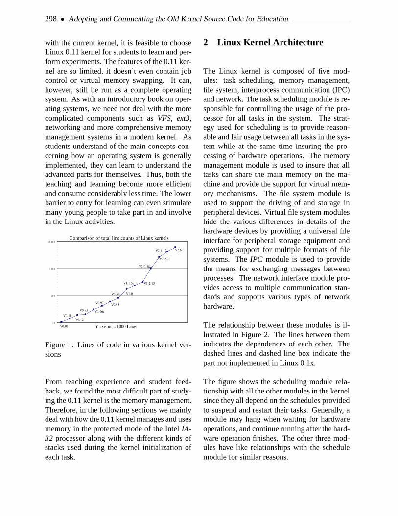
298 • Adopting and Commenting the Old Kernel Source Code for Education
with the current kernel, it is feasible to chooseLinux 0.11 kernel for students to learn and per-form experiments. The features of the 0.11 ker-nel are so limited, it doesn’t even contain jobcontrol or virtual memory swapping. It can,however, still be run as a complete operatingsystem. As with an introductory book on oper-ating systems, we need not deal with the morecomplicated components such asVFS, ext3,networking and more comprehensive memorymanagement systems in a modern kernel. Asstudents understand of the main concepts con-cerning how an operating system is generallyimplemented, they can learn to understand theadvanced parts for themselves. Thus, both theteaching and learning become more efficientand consume considerably less time. The lowerbarrier to entry for learning can even stimulatemany young people to take part in and involvein the Linux activities.
Comparison of total line counts of Linux kernels
V1.2.13
V1.0
V1.1.52
V0.01
V0.11V0.12
V0.95 V0.96a
V0.97 V0.98
V0.99
V2.0.38
V2.2.20
V2.4.17 V2.6.0
Y axis unit: 1000 Lines
Figure 1: Lines of code in various kernel ver-sions
From teaching experience and student feed-back, we found the most difficult part of study-ing the 0.11 kernel is the memory management.Therefore, in the following sections we mainlydeal with how the 0.11 kernel manages and usesmemory in the protected mode of the IntelIA-32 processor along with the different kinds ofstacks used during the kernel initialization ofeach task.
2 Linux Kernel Architecture
The Linux kernel is composed of five mod-ules: task scheduling, memory management,file system, interprocess communication (IPC)and network. The task scheduling module is re-sponsible for controlling the usage of the pro-cessor for all tasks in the system. The strat-egy used for scheduling is to provide reason-able and fair usage between all tasks in the sys-tem while at the same time insuring the pro-cessing of hardware operations. The memorymanagement module is used to insure that alltasks can share the main memory on the ma-chine and provide the support for virtual mem-ory mechanisms. The file system module isused to support the driving of and storage inperipheral devices. Virtual file system moduleshide the various differences in details of thehardware devices by providing a universal fileinterface for peripheral storage equipment andproviding support for multiple formats of filesystems. TheIPC module is used to providethe means for exchanging messages betweenprocesses. The network interface module pro-vides access to multiple communication stan-dards and supports various types of networkhardware.
The relationship between these modules is il-lustrated in Figure 2. The lines between themindicates the dependences of each other. Thedashed lines and dashed line box indicate thepart not implemented in Linux 0.1x.
The figure shows the scheduling module rela-tionship with all the other modules in the kernelsince they all depend on the schedules providedto suspend and restart their tasks. Generally, amodule may hang when waiting for hardwareoperations, and continue running after the hard-ware operation finishes. The other three mod-ules have like relationships with the schedulemodule for similar reasons.

2005 Linux Symposium • 299
Figure 2: The relationship between Linux ker-nel modules
The remaining modules have implicit depen-dences with each other. The scheduling subsys-tem needs memory management to adjust thephysical memory space used by each task. TheIPC subsystem requires the memory manage-ment module to support shared memory com-munication mechanisms. Virtual file systemscan also use the network interface to supportthe network file system (NFS). The memorymanagement subsystem may also use the filesystem to support the swapping of memory datablocks.
From the monolithic model structure, we canillustrate the main kernel modules in Figure 3based on the structure of the Linux 0.11 kernelsource code.
3 Memory Usage
In this section, we first describe the usage ofphysical memory in Linux 0.1x kernel. Thenwe explain the memorysegmentation, paging,multitasking and theprotection mechanisms.Finally, we summarize the relationship betweenvirtual, linear, and physical address for the codeand data in the kernel and for each task.
Figure 3: Kernel structure framework
3.1 Physical Memory
In order to use the physical memory of the ma-chine efficiently with Linux 0.1x kernel, thememory is divided into several areas as shownin Figure 4.
Figure 4: The regions of physical memory
As shown in Figure 4, the kernel code anddata occupies the first portion of the physi-cal memory. This is followed by the cacheused for block devices such as hard disks andfloppy drives eliminating the memory spaceused by the adapters andROM BIOS. When a
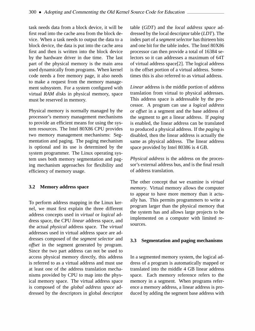
300 • Adopting and Commenting the Old Kernel Source Code for Education
task needs data from a block device, it will befirst read into the cache area from the block de-vice. When a task needs to output the data to ablock device, the data is put into the cache areafirst and then is written into the block deviceby the hardware driver in due time. The lastpart of the physical memory is the main areaused dynamically from programs. When kernelcode needs a free memory page, it also needsto make a request from the memory manage-ment subsystem. For a system configured withvirtual RAM disksin physical memory, spacemust be reserved in memory.
Physical memory is normally managed by theprocessor’s memory management mechanismsto provide an efficient means for using the sys-tem resources. The Intel 80X86 CPU providestwo memory management mechanisms: Seg-mentation and paging. The paging mechanismis optional and its use is determined by thesystem programmer. The Linux operating sys-tem uses both memory segmentation and pag-ing mechanism approaches for flexibility andefficiency of memory usage.
3.2 Memory address space
To perform address mapping in the Linux ker-nel, we must first explain the three differentaddress concepts used invirtual or logical ad-dress space, the CPUlinear address space, andthe actualphysicaladdress space. Thevirtualaddresses used in virtual address space are ad-dresses composed of thesegment selectorandoffset in the segment generated by program.Since the two part address can not be used toaccess physical memory directly, this addressis referred to as a virtual address and must useat least one of the address translation mecha-nisms provided by CPU to map into the phys-ical memory space. The virtual address spaceis composed of theglobal address spacead-dressed by the descriptors in global descriptor
table (GDT) and thelocal address spacead-dressed by the local descriptor table (LDT). Theindex part of asegment selectorhas thirteen bitsand one bit for the table index. The Intel 80X86processor can then provide a total of 16384 se-lectors so it can addresses a maximum of 64Tof virtual address space[2]. The logical addressis the offset portion of a virtual address. Some-times this is also referred to as virtual address.
Linear address is the middle portion of addresstranslation from virtual to physical addresses.This address space is addressable by the pro-cessor. A program can use alogical addressor offset in a segment and the base address ofthe segment to get a linear address. Ifpagingis enabled, the linear address can be translatedto produced a physical address. If thepagingisdisabled, then the linear address is actually thesame as physical address. The linear addressspace provided by Intel 80386 is 4 GB.
Physical addressis the address on the proces-sor’s external address bus, and is the final resultof address translation.
The other concept that we examine isvirtualmemory. Virtual memory allows the computerto appear to have more memory than it actu-ally has. This permits programmers to write aprogram larger than the physical memory thatthe system has and allows large projects to beimplemented on a computer with limited re-sources.
3.3 Segmentation and paging mechanisms
In a segmented memory system, the logical ad-dress of a program is automatically mapped ortranslated into the middle 4 GB linear addressspace. Each memory reference refers to thememory in a segment. When programs refer-ence a memory address, a linear address is pro-duced by adding the segment base address with

2005 Linux Symposium • 301
Figure 5: The translation between virtual orlogical, linear and physical address
the logical address visible to the programmer.If pagingis not enabled, at this time, the linearaddress is sent to the external address bus of theprocessor to access the corresponding physicaladdress directly.
If pagingis enabled on the processor, the linearaddress will be translated by thepagingmech-anism to get the final physical correspondingphysical address. Similar to the segmentation,paging allow us to relocate each memory ref-erence. The basic theory of paging is that theprocessor divides the whole linear space into
pages of 4 KB. When programs request mem-ory, the processor allocates memory in pagesfor the program.
Since Linux 0.1x kernel uses only onepage di-rectory, the mapping function from linear tophysical space is same for the kernel and pro-cesses. To prevent tasks from interfering witheach other and the kernel, they have to occupydifferent ranges in the linear address space. TheLinux 0.1x kernel allocates 64MB of linearspace for each task in the system, the systemcan therefor hold at most 64 simultaneous tasks(64MB * 64 = 4G) before occupying the entireLinear address space as illustrated in Figure 6.
Figure 6: The usage of linear address space inthe Linux 0.1x kernel
3.4 The relationship between virtual, lin-ear and physical address
We have briefly described the memory segmen-tation and paging mechanisms. Now we willexamine the relationship between the kerneland tasks in virtual, linear and physical addressspace. Since the creation oftasks 0and1 arespecial, we’ll explain them separately.
3.4.1 The address range of kernel
For the code and data in the Linux 0.1x ker-nel, the initialization inhead.s has alreadyset the limit for the kernel and data segments to

302 • Adopting and Commenting the Old Kernel Source Code for Education
be 16MB in size. These two segments over-lap at the same linear address space startingfrom address 0. Thepage directoryandpagetable for kernel space are mapped to 0-16MBin physical memory (the same address range inboth spaces). This is all of the memory thatthe system contains. Since one page table canmanage or map 4MB, the kernel code and dataoccupies four entries in thepage directory. Inother words, there are four secondary page ta-bles with 4MB each. As a result, the addressin the kernel segment is the same in the physi-cal memory. The relationship of these three ad-dress spaces in the kernel is depicted in Figure7.
Figure 7: The relationship of the three addressspaces in a 0.1x kernel
As seen in Figure 7, the Linux 0.1x kernelcan manage at most 16MB of physical mem-ory in 4096 page frames. As explained ear-lier, we know that: (1) the address range ofkernel code and data segments are the same asin the physical memory space. This configura-tion can greatly reduce the initialization oper-ations the kernel must perform. (2)GDT and
Interrupt Descriptor Table (IDT) are in the ker-nel data segment, thus they are located in thesame address in both address spaces. In theexecution of code insetup.s in real mode,we have setup both temporaryGDT andIDT atonce. These are required before entering pro-tected mode. Since they are located by physicaladdress0x90200 and this will be overlappedand used for block device cache, we have torecreateGDT and IDT in head.s after en-tering protected mode. The segment selectorsneed to be reloaded too. Since the locations ofthe two tables do not change after entering pro-tected mode, we do not need to move or recre-ate them again. (3) All tasks excepttask 0needadditional physical memory pages in differentlinear address space locations. They need thememory management module to dynamicallysetup their own mapping entries in thepage di-rectoryandpage table. Although the code andstatic data oftask 1are located in kernel space,we need to obtain new pages to prevent interfer-ence withtask 0. As a result,task 1also needsits own page entries.
While the default manageable physical mem-ory is 16MB, a system need not contain 16MBmemory. A machine with only 4MB or even2MB could run Linux 0.1x smoothly. For a ma-chine with only 4MB, the linear address range4MB to 16MB will be mapped to nonexistentphysical space by the kernel. This does not dis-rupt or crash the kernel. Since the kernel knowsthe exact physical memory size from the initial-ization stage, no pages will be mapped into thisnonexistent physical space. In addition, sincethe kernel has limited the maximum physicalmemory to be 16MB at boot time (inmain()corresponding tostartkernel() ), memoryover 16MB will be left unused. By addingsome page entries for the kernel and chang-ing some of the kernel source, we certainly canmake Linux 0.1x support more physical mem-ory.

2005 Linux Symposium • 303
3.4.2 The address space relationship fortask 0
Task 0is artificially created or configured andrun by using a special method. The limits of itscode and data segments are set to the 640KB in-cluded in the kernel address space. Nowtask 0can use the kernel page entries directly withoutthe need for creating new entries for itself. Asa result, its segments are overlapped in linearaddress space too. The three space relationshipis shown in Figure 8.
Figure 8: The relationship of three addressspaces for task 0
As task 0 is totally contained in the kernelspace, there is no need to allocate pages fromthe main memory area for it. The kernel stackand the user stack fortask 0are included thekernel space.Task 0still has read and writerights in the stacks since the page entries usedby the kernel space have been initialized to bereadable and writable with user privileges. Inother words, the flags in page entries are set asU/S=1, R/W=1.
3.4.3 The address space relationship fortask 1
Similar totask 0, task 1is also a special case inwhich the code and data segment are includedin kernel module. The main difference is thatwhen forkingtask 1, one free page is allocatedfrom the main memory area to duplicate andstoretask 0’s page table entries fortask 1. Asa result,task 1has its ownpage tableentries inthepage directoryand is located at range from64MB to 128MB (actually 64MB to 64MB +640KB) in linear address space. One additionalpage is allocated for task 1 to store itstaskstructure (PCB)and is used as its kernel modestack. The task’sTask State Segment (TSS)isalso contained in task’s structure as illustratedin Figure 9.
Figure 9: The relationship of the three addressspaces in task 1
Task 1and task 0will share their user stackuser_stack[] (refer tokernel/sched.c , lines 67-72). Thus, the stack space should be‘ ‘clean” beforetask 1uses it to ensure that there

304 • Adopting and Commenting the Old Kernel Source Code for Education
is no unnecessary data on the stack. When fork-ing task 1, the user stack is shared betweentask0 andtask 1. However whentask 1starts run-ning, the stack operating intask 1would causethe processor to produce a page fault becausethe page entries have been modified to be readonly. The memory management module willtherefor need allocate a free page fortask 1’sstack.
3.4.4 The address space relationship forother tasks
For task 2and higher, the parent istask 1or theinit process. As described earlier, Linux 0.1xcan have 64 tasks running synchronously in thesystem. Now we will detail the address spaceusage for these additional tasks.
Beginning withtask 2, if we designatenr asthe task number, the starting location fortasknr will be at nr * 64MB in linear addressspace.Task 2, for example, begins at address 2* 64MB = 128MB in the linear address space,and the limits of code and data segments are setto 64MB. As a result, the address range occu-pied by task 2is from 128MB to 192MB, andhas 64MB/4MB = 16 entries in the page direc-tory. The code and data segments both mapto the same range in the linear address space.Thus they also overlap with the same addressrange as illustrated in Figure 10.
After task 2has forked, it will call the func-tion execve() to run a shell program such asbash. Just after the creation oftask 2and be-fore callexecve() , task 2is similar totask 1in the three address space relationship for codeand data segments except the address range oc-cupied in linear address space has the rangefrom 128MB to 192MB. Whentask 2’scodecalls execve() to load and run a shell pro-gram, the page entries are copied fromtask 1and corresponding memory pages are freed and
Figure 10: The relationship of the three addressspaces in tasks beginning with task 2
new page entries are set for the shell program.Figure 10 shows this address space relation-ship. The code and data segment fortask 1arereplaced with that of the shell program, and onephysical memory page is allocated for the codeof the shell program. Notice that although thekernel has allocated 64MB linear space fortask2, the operation of allocating actual physicalmemory pages for code and data segments ofthe shell program is delayed until the programis running. This delayed allocation is called de-mand paging.
Beginning with kernel version 0.99.x, the usageof memory address space changed. Each taskcan use the entire 4G linear space by changingthe page directory for each tasks as illustratedin Figure 11. There are even more changes arein current kernels.

2005 Linux Symposium • 305
Figure 11: The relationship of the three addressspace for tasks in newer kernels
4 Stack Usage
This section describes several different meth-ods used during the processing of kernel boot-ing and during normal task stack operations.Linux 0.1x kernel uses four different kinds ofstacks: the temporary stack used for systembooting and initialization under real addressmode; The kernel initialization stack used afterthe kernel enters protected mode, and the userstack fortask 0after moving into task 0; Thekernel stack of each task used when running inthe kernel and the user stacks for each task ex-cept fortasks 0 and 1.
There are two main reasons for using four dif-ferent stacks (two used only temporarily forbooting) in Linux. First, when entering pro-tected from real mode, the addressing methodused by the processor has changed. Thus thekernel needs to rearrange the stack area. In ad-dition, to solve the protection problems broughtby the new privilege level on processor, weneed to use different stacks for kernel code at
level 0 and for user code at level 3 respectively.When a task runs in the kernel, it uses the ker-nel mode stack pointed by the values inss0andesp0 fields of itsTSSand stores the task’suser stack pointer in this stack. When the con-trol returns to the user code or to level 3, theuser stack pointer will be popped out, and thetask continues to use the user stack.
4.1 Initialization period
When theROM BIOScode boots and loadsthe bootsect into memory at physical address0x7C00 , no stack is used until it is movedto the location0x9000:0 . The stack is thenset at0x9000:0xff00 . (refer to line 61–62 in boot/bootsect.s ). After control istransferred tosetup.s , the stack remains un-changed.
When control is transferred tohead.s , theprocessor runs in protected mode. At this time,the stack is setup at the location ofuser_stack[] in the kernel code segment (line 31in head.s ). The kernel reserves one 4 KBpage for the stack defined at line 67–72 insched.c as illustrated in Figure 12.
This stack area is still used after the controltransfers intoinit/main.c until the execu-tion of move_to_user_mode() to hand thecontrol over totask 0. The above stack is thenused as a user stack fortask 0.
4.2 Task stacks
For the processor privilege levels 0 and 3 usedin Linux, each task has two stacks: kernel modestack and user mode stack used to run kernelcode and user code respectively. Other than theprivilege levels, the main difference is that thesize of kernel mode stack is smaller than thatof the user mode stack. The former is located

306 • Adopting and Commenting the Old Kernel Source Code for Education
Figure 12: The stack used for kernel code afterentering protected mode
at the bottom in a page coexisting with task’sstructure, and no more than 4KB in size. Thelater can grow down to nearly 64MB in userspace.
As described, each task has its own 64MB log-ical or linear address space except fortask 0and1. When a task was created, the bottom ofits user stack is located close to the end of the64MB space. The top portion of the user spacecontains additional environmental parametersand command line parameters in a backwardsorientation, and then the user stack as illus-trated in Figure 13.
Task code at privilege level 3 uses this stack allof the time. Its corresponding physical memorypage is mapped by paging management codein the kernel. Since Linux utilizes thecopy-on-write[3] method, both the parent and childprocess share the same user stack memory untilone of them perform a write operation on the
Figure 13: User stack in task’s logical space
stack. Then the memory manager will allocateand duplicate the stack page for the task.
Similar to the user stack, each task has its ownkernel mode stackused when operating in thekernel code. This stack is located in the mem-ory to pointed by the values inss0 , esp0fields in task’sTSS. ss0 is the stack segmentselector like thedata selectorin the kernel.esp0 indicates the stack bottom. Whenevercontrol transfers to the kernel code from usercode, the kernel mode stack for the task alwaysstarts fromss0:esp0 , giving the kernel codean empty stack space. The bottom of a task’skernel stack is located at the end of a mem-ory page where the task’s data structure begins.This arrangement is setup by making the privi-lege level 0 stack pointer inTSSpoint to the endof the page occupied by the task’s data struc-ture when forking a new task. Refer to line 93in kernel/fork.c as below:
p->tss.esp0 = PAGE_SIZE+(long)p;p->tss.ss0 = 0x10;
p is the pointer of the new task structure,tssis the structure of the task status segment. Thekernel request a free page to store the task struc-ture pointed byp. The tss structure is a field inthe task structure. The value oftss.ss0 isset to the selector of kernel data segment andthe tss.esp0 is set to point to the end of thepage as illustrated in Figure 14.
As a matter of fact,tss.esp0 points to thebyte outside of the page as depicted in the fig-

2005 Linux Symposium • 307
Figure 14: The kernel mode stack of a task
ure. This is because the Intel processor de-creases the pointer before storing a value on thestack.
4.3 The stacks used by task 0 and task 1
Both task 0or idle task andtask 1or init taskhave some special properties. Althoughtask 0and task 1have the same code and data seg-ment and 640KB limits, they are mapped intodifferent ranges in linear address space. Thecode and data segments oftask 0begins at ad-dress 0, andtask 1 begins at address 64MBin the linear space. They are both mappedinto the same physical address range from 0to 640KB in kernel space. After calling thefunction move_to_user_mode() , the ker-nel mode stacks oftask 0andtask 1are locatedat the end of the page used for storing theirtask structures. The user stack oftask 0is thesame stack originally used after entering pro-tected mode; the space foruser_stack[]array defined insched.c program. Sincetask1 copiestask 0’s user stack when forking, theyshare the same stack space in physical memory.When task 1starts running, however, a pagefault exception will occur whentask 1writesto its user stack because the page entries fortask 1have been initialized as read-only. Atthis moment, the kernel will allocate a free page
in main memory area for the stack oftask 1inthe exception handler, and map it to the loca-tion of task 1’s user stack in the linear space.From now on,task 1has its own separate userstack page. As a result, the user stack fortask0 should be “clean” beforetask 1uses the userstack to ensure that the page of stack duplica-tion does not contain useless data fortask 1.
The kernel mode stack fortask 0is initializedin its static data structure. Then its user stack isset up by manipulating the contents of the stackoriginally used after entering protected modeand emulating the interrupt return operation us-ing IRET instruction as illustrated in Figure 15.
031
Figure 15: Stack contents while returning fromprivilege level 0 to 3
As we know, changing the privilege level willchange the stack and the old stack pointerswill be stored onto the new stack. To emu-late this case, we first push thetask 0’s stackpointer onto the stack, then the pointer of thenext instruction intask 0. Finally we run theIRET instruction. This causes the privilegelevel change and control to be transferred totask 0. In the Figure 15, the oldSSfield storesthe data selector ofLDT for task 0(0x17) andthe oldESPfield value is not changed since thestack will be used as the user stack fortask 0.The oldCSfield stores the code selector (0x0f)for task 0. The oldEIP points to the next in-struction to be executed. After the manipula-tion, aIRET instruction switches the privileges
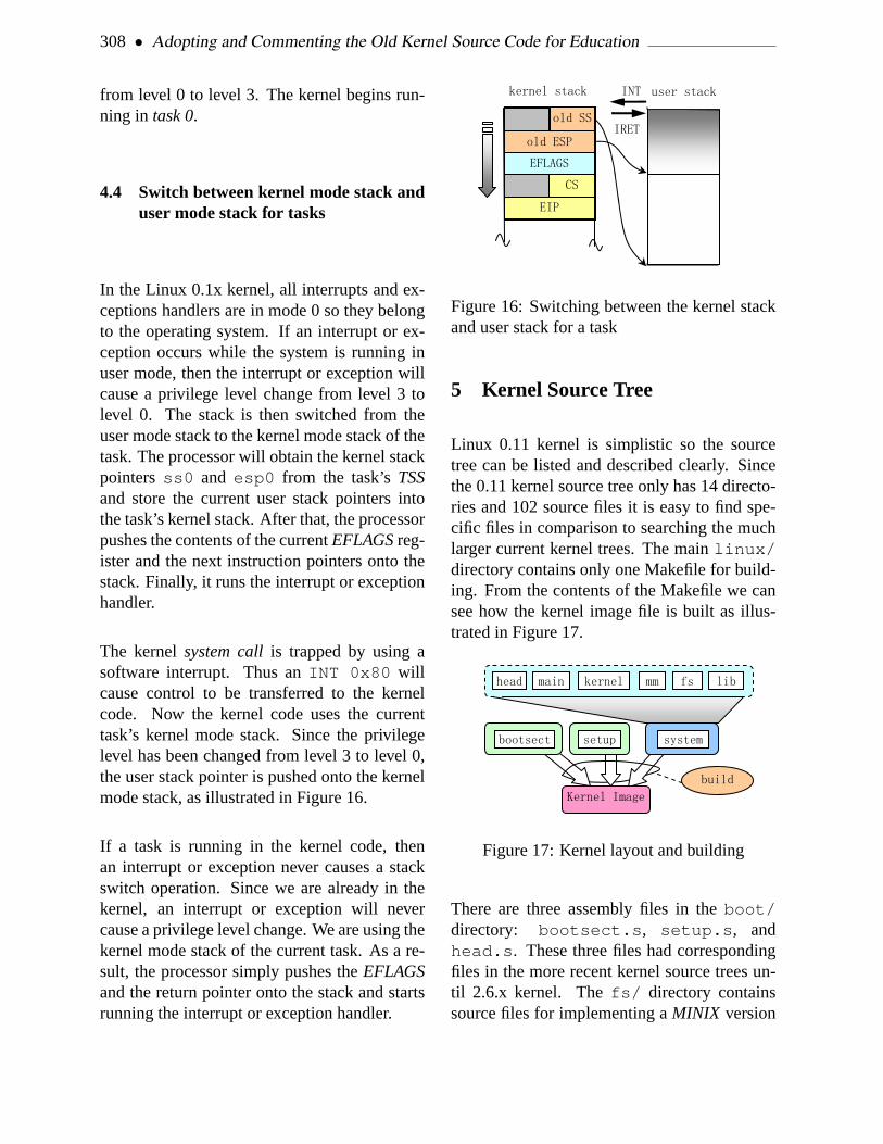
308 • Adopting and Commenting the Old Kernel Source Code for Education
from level 0 to level 3. The kernel begins run-ning in task 0.
4.4 Switch between kernel mode stack anduser mode stack for tasks
In the Linux 0.1x kernel, all interrupts and ex-ceptions handlers are in mode 0 so they belongto the operating system. If an interrupt or ex-ception occurs while the system is running inuser mode, then the interrupt or exception willcause a privilege level change from level 3 tolevel 0. The stack is then switched from theuser mode stack to the kernel mode stack of thetask. The processor will obtain the kernel stackpointersss0 and esp0 from the task’sTSSand store the current user stack pointers intothe task’s kernel stack. After that, the processorpushes the contents of the currentEFLAGSreg-ister and the next instruction pointers onto thestack. Finally, it runs the interrupt or exceptionhandler.
The kernelsystem callis trapped by using asoftware interrupt. Thus anINT 0x80 willcause control to be transferred to the kernelcode. Now the kernel code uses the currenttask’s kernel mode stack. Since the privilegelevel has been changed from level 3 to level 0,the user stack pointer is pushed onto the kernelmode stack, as illustrated in Figure 16.
If a task is running in the kernel code, thenan interrupt or exception never causes a stackswitch operation. Since we are already in thekernel, an interrupt or exception will nevercause a privilege level change. We are using thekernel mode stack of the current task. As a re-sult, the processor simply pushes theEFLAGSand the return pointer onto the stack and startsrunning the interrupt or exception handler.
Figure 16: Switching between the kernel stackand user stack for a task
5 Kernel Source Tree
Linux 0.11 kernel is simplistic so the sourcetree can be listed and described clearly. Sincethe 0.11 kernel source tree only has 14 directo-ries and 102 source files it is easy to find spe-cific files in comparison to searching the muchlarger current kernel trees. The mainlinux/directory contains only one Makefile for build-ing. From the contents of the Makefile we cansee how the kernel image file is built as illus-trated in Figure 17.
Figure 17: Kernel layout and building
There are three assembly files in theboot/directory: bootsect.s , setup.s , andhead.s . These three files had correspondingfiles in the more recent kernel source trees un-til 2.6.x kernel. Thefs/ directory containssource files for implementing aMINIX version

2005 Linux Symposium • 309
1.0 file system. This file system is a clone of thetraditional UN*X file system and is suitable forsomeone learning to understand how to imple-ment a usable file system. Figure 18 depicts therelationship of each files in thefs/ directory.
Figure 18: File relationships in fs/ directory
The fs/ files can be divided into four types.The first is the block cache manager filebuffer.c . The second is the files concern-ing with low level data operation files suchinode.c . The third is files used to processdata related to char, block devices and regularfiles. The fourth is files used to execute pro-grams or files that are interfaces to user pro-grams.
The kernel/ directory contains three kindsof files as depicted in Figure 19.
The first type is files which deal with hardwareinterrupts and processor exceptions. The sec-ond type is files manipulating system calls from
Figure 19: Files in the kernel/ directory
user programs. The third category is files im-plementing general functions such as schedul-ing and printing messages from the kernel.
Block device drivers for hard disks, floppydisks and ram disks reside in a subdirectoryblk_drv/ in the kernel/ , thus the Linux0.11 kernel supports only three classical blockdevices. Because Linux evolved from a ter-minal emulation program, the serial terminaldriver is also included in this early kernel inaddition to the necessary console character de-vice. Thus, the 0.11 kernel contains at least twotypes of char device drivers as illustrated in Fig-ure 20.
The remaining directories in the kernel sourcetree include, init, mm, tools, andmath . The include/ contains the head filesused by the other kernel source files.init/contains only the kernel startup filemain.c ,in which, all kernel modules are initialized andthe operating system is prepared for use. Themm/ directory contains two memory manage-ment files. They are used to allocate and freepages for the kernel and user programs. Asmentioned, the mm in 0.11 kernel uses demandpaging technology. Themath/ directory onlycontains math source code stubs as 387 emula-

310 • Adopting and Commenting the Old Kernel Source Code for Education
Figure 20: Character devices in Linux 0.11 ker-nel
tion did not appear until the 0.12 kernel.
6 Experiments with the 0.1x kernel
To facilitate understanding of the Linux 0.11kernel implementation, we have rebuilt arunnable Linux 0.11 system, and designed sev-eral experiments to watch the kernel internalactivities using theBochs PC emulator. Bochsis excellent for debugging operating systems.TheBochssoftware package contains an inter-nal debugging tool, which we can use to ob-serve the dynamic data structures in the kerneland examine the contents of each register on theprocessor.
It is an interesting exercise to install the Linux0.11 system from scratch. It is a good learningexperience to build a root file system image fileunder Bochs.
Modifying and compiling the kernel sourcecode are certainly the most important experi-ments for learning about operating systems. Tofacilitate the process, we provide two environ-ments in which, one can easily compile the ker-nel. One is the originalGNU gcc environment
under Linux 0.11 system in Bochs. The otheris for more recent Linux systems such asRedHat 9 or Fedora. In the former environment,the 0.11 kernel source code needs no modifi-cations to successfully compile. For the laterenvironment one needs to modify a few linesof code to correct syntax errors. For peoplefamiliar with MASM andVC environment un-der windows, we even provide modified 0.11kernel source code that can compile. Offer-ing source code compatible with multiple envi-ronments and providing forums for discussionhelps popularize linux and the linux communitywith new people interested in learning aboutoperating systems:-)
7 Summary
From observing people taking operating systemcourses with the old Linux kernel, we foundthat almost all the students were highly inter-ested in the course. Some of them even startedprogramming their own operating systems.
The 0.11 kernel contains only the basic featuresthat an operating system must have. As a result,there are many important features not imple-mented in 0.11 kernel. We now plan to adopteither the 0.12 or 0.98 kernel for teaching pur-poses to include job control, virtualFS, virtualconsole and even network functions. Due totime limitations in the course, several simpli-fications and careful selection of material willbe needed.
References
[1] Albert S. Woodhull AndrewS. Tanenbaum.OPERATING SYSTEMS:Design and Implementation.Prentice-Hall, Inc., 1997.

2005 Linux Symposium • 311
[2] Patrick P. Gelsinger John H. Crawford.Programming the 80386. SYBEX Inc.,1987.
[3] Robert Love.Linux Kernel Development.Sams Inc., 2004.
[4] M.J.Bach.The Design of Unix OperatingSystem. Prentice-Hall, Inc., 1986.
[5] Linus Torvalds. LINUX – a free unix-386kernel. October 1991.

312 • Adopting and Commenting the Old Kernel Source Code for Education