PROCEDURE FOR SELECTING AND EVALUATING A SPECIAL …
22
PROCEDURE FOR SELECTING AND EVALUATING A SPECIAL PURPOSE MOTOR by Clifford P. Cook Senior Specialist and Supervisor, Rotating Equipment Section Texaco, Incorporated Bellaire, Texas and Michael J. Costello Electrical Machinery Consultant, Instrumentation and Electrical Group Texaco, Incorporated Houston, Texas Clford P. Cook is Senior Specialist and Supervisor of the Rotating Equipment Sec- tion of Texaco, Inc., Central Engineering Department. This gro is responsible for the specication, selection, design, review, installation, and startup of rotating equip- mentfor major domestic and foreign Texaco refine and chemical plant expansions. He has a total of more than 25 years ex- perience with rotating equipment. Mr. Cook holds a B.S. degree from the U.S. Merchant Marine Academy, and an M.S. degree in Mechan- ical Engineering from Lehigh Universi. He is a Registered Engineer in the State ofTexas, a member of the API Su bcommittee on Mechanical equipment, the Vibration Institute, and the IEEE. Michael J. Costello is an Electrical Machine Consultant in the Instrumenta- tion and Electrical group of Texaco Cen- tral Engineering and Purchasing Division in Houston, Texas. From 1 980 to 1 988, he was employed by Nippes Professional As- sociates, Inc., and was President of Mag- netic Products and Services, Inc., from 1988 to June 1991. He has performed elec- trical and substation design of power sys- tems as well as extensive mechanical and electrical analysis ofthe performance of electrical machines up to 500 MW. Mr. Costello has developed motor qualipurchasing programs for clients in the petrochemical industry and has peormed con- siderable field engineering in the correction and analysis ofmotor problems and failures. Mr. Costello graduatedfrom New Jersey Institute ofTechnolo- gy in 1980, as an Electrical Engineer. He is a member of the IEEE and is presently serving on Working Group PI 12 and P841 for the revision of Induction Motor Standards as well as the Induction Machine Subcommittee of the PES. He is also a member of the Vibration Institute. ABSTRACT During recent years, there has been considerable interest in motors. This interest has stemmed from what appears to be an 187 increase in motor problems. As a result of this, along with the need for machinery reliability, manufacturers and users are starting to evaluate the motor's overall performance. In a petroleum or petrochemical facility, the department respon- sible for motor reliability often consists of mechanical engineers who may have had little or no formal training in motor construction or design. In order to evaluate and troubleshoot motor problems however, their construction features must be understood. In order to understand even the simplest of motor problems, it is important that one have knowledge of the various manufacturing and construction features which make up a motor. Only in this manner can an engineer decide on proper methods of repair, and whether or not they may be in contradiction with the basic design or construction principles. The components and construction features of induction motors are described and a technical tabulation is presented which, when completed by the manufacturer, can be used to evaluate the new motor. In process manufacturing tests normally specified to in- crease the reliability of motors are also described in detail. INTRODUCTION As a result of what appears to be an increase in motor problems and failures, most users in the petroleum and chemical industries are critically evaluating special purpose induction motors when they are specified and purchased. When purchasing special pur- pose motors, by far the most important consideration involves obtaining a motor which will provide years of reliable service. It is recommended that the following aspects be incorporated into the motor procurement as stringent spec ifications alone do not guarantee a well running and reliable machine [ 1]. • Utilize detailed motor specifications which rely on industry standards if applicable to the application. • Qualify various motor manufacturers to ascertain their man- ufacturing, quality control, and testing capabilities. • Contact other users of identical machines to learn of their experience. • Evaluate the motor from a technical and from a commercial standpoint. Determine the various manufacturers' design features and drawbacks. • Perform a comprehensive design review regarding both the electrical and mechanical designs.
Transcript of PROCEDURE FOR SELECTING AND EVALUATING A SPECIAL …

PROCEDURE FOR SELECTING AND
EVALUATING A SPECIAL PURPOSE MOTOR
by
Clifford P. Cook
Senior Specialist and Supervisor, Rotating Equipment Section Texaco, Incorporated
Bellaire, Texas and
Michael J. Costello
Electrical Machinery Consultant, Instrumentation and Electrical Group Texaco, Incorporated
Houston, Texas
Clifford P. Cook is Senior Specialist and Supervisor of the Rotating Equipment Section of Texaco, Inc . , Central Engineering Department. This group is responsible for the specification, selection, design, review, installation, and startup of rotating equipmentfor major domestic and foreign Texaco refinery and chemical plant expansions. He has a total of more than 25 years experience with rotating equipment.
Mr. Cook holds a B.S. degree from the U.S. Merchant Marine Academy, and an M.S. degree in Mechanical Engineering from Lehigh University. He is a Registered Engineer in the State ofTexas, a member of the API Subcommittee on Mechanical equipment, the Vibration Institute, and the IEEE.
Michael J. Costello is an Electrical Machinery Consultant in the Instrumentation and Electrical group of Texaco Central Engineering and Purchasing Division in Houston, Texas. From 1 980 to 1 988, he was employed by Nippes Professional Associates, Inc . , and was President of Magnetic Products and Services, Inc. , from 1988 to June 1 991 . He has performed electrical and substation design of power systems as well as extensive mechanical and
electrical analysis of the performance of electrical machines up to 500 MW.
Mr. Costello has developed motor quality purchasing programs for clients in the petrochemical industry and has performed considerable field engineering in the correction and analysis of motor problems and failures .
Mr. Costello graduated from New Jersey Institute ofTechnology in 1 980, as an Electrical Engineer. He is a member of the IEEE and is presently serving on Working Group PI 1 2 and P841 for the revision of Induction Motor Standards as well as the Induction Machinery Subcommittee of the PES. He is also a member of the Vibration Institute .
ABSTRACT
During recent years, there has been considerable interest in motors. This interest has stemmed from what appears to be an
187
increase in motor problems. As a result of this, along with the need for machinery reliability, manufacturers and users are starting to evaluate the motor's overall performance.
In a petroleum or petrochemical facility, the department responsible for motor reliability often consists of mechanical engineers who may have had little or no formal training in motor construction or design. In order to evaluate and troubleshoot motor problems however, their construction features must be understood.
In order to understand even the simplest of motor problems, it is important that one have knowledge of the various manufacturing and construction features which make up a motor. Only in this manner can an engineer decide on proper methods of repair, and whether or not they may be in contradiction with the basic design or construction principles.
The components and construction features of induction motors are described and a technical tabulation is presented which, when completed by the manufacturer, can be used to evaluate the new motor. In process manufacturing tests normally specified to increase the reliability of motors are also described in detail.
INTRODUCTION
As a result of what appears to be an increase in motor problems and failures, most users in the petroleum and chemical industries are critically evaluating special purpose induction motors when they are specified and purchased. When purchasing special purpose motors, by far the most important consideration involves obtaining a motor which will provide years of reliable service.
It is recommended that the following aspects be incorporated into the motor procurement as stringent specifications alone do not guarantee a well running and reliable machine [ 1].
• Utilize detailed motor specifications which rely on industry standards if applicable to the application.
• Qualify various motor manufacturers to ascertain their manufacturing, quality control, and testing capabilities.
• Contact other users of identical machines to learn of their experience.
• Evaluate the motor from a technical and from a commercial standpoint. Determine the various manufacturers' design features and drawbacks.
• Perform a comprehensive design review regarding both the electrical and mechanical designs.

188 PROCEEDINGS OF THE TWENTIETH TURBOMACHINERY SYMPOSIUM
• Develop a comprehensive shop inspection and witness test plan.
The design principals and manufacturing and test procedures necessary for users to technically evaluate a special purpose motor are discussed. It is recognized that definitions for special purpose motors may vary from user to user; however, API 54 1 has defined it as follows:
Special purpose motors are those motors driving unspared equipment in critical service, motors rated over 1000 horsepower, motors driving high inertia loads, motors that are part of a complete train requiring vibration sensitivity criteria, or motors which must operate in abnormally hostile environments [2].
TECHNICAL TABULATION
It is recommended that a motor technical tabulation be included in the request for quotation (RFQ). This should be completed and submitted by the motor manufacturer along with the quotation. The tabulation included in the APPENDIX has proven invaluable when determining the technical and design aspects of the proposed motor. It is also an excellent source or outline document during the motor design review meeting. The amount of detail contained in the tabulation is critical and necessary when comparing the various manufacturers' proposed designs; however, as a result, it is necessary to completely understand the various items. As this tutorial is directed towards the mechanical engineer, the items specifically relating to motors are reviewed in detail (section on TECHNICAL TABULATION). The remaining table lists mostly mechanical items which are very familiar to rotating machinery specialists and as such, are not discussed here.
The following is an explanation from "Special Purpose Induction Motor Technical Tabulation" in the APPENDIX.
Explanation of Technical Tabulation Items
Manufacturer
The manufacturer listed on the technical tabulation should be checked against the users acceptable vendors list issued for the project.
Place of Manufacturer
The place of manufacture should be compared against the acceptable or qualified manufacturing locations.
Motor Model Number
The manufacturer should be queried as to where the application being offered falls within the motor frame capability. Additionally, refer to Laminations of the TECHNICAL TABULATION which asks for maximum and minimum core length that the frame can handle along with the core length of the machine being offered. The diameter and length of the rotor and stator cores are significant items with regard to the horsepower rating and the critical speed of the motor.
Guaranteed Efficiency at Normal Operation Point
It should be confirmed that the motor manufacturer was given the normal operating point horsepower. For compressor applications this could be in the range of 70 to 80 percent of the nameplate rating of the motor. Typically, motor manufacturers guarantee the efficiency at full load horsepower. The motor, however, is most likely not going to be run at full load; therefore, the guaranteed efficiency should be at the driven equipment's normal operating point. Normal operating point horsepower can be obtained from the compressor data sheets.
Enclosure Type
TEWAC enclosure (YIN). Consideration should be given requiring TEW AC enclosures since this design minimizes the entrance of corrosive atmospheres or harmful contaminants into the motor windings.
Top or bottom mounted coolers. It is suggested that coolers be mounted below the motor. Top mounted coolers may be offered as an alternative when there is considerable economic advantage and manufacturing expertise. If the motor manufacturer indicates that he has not made motors with coolers mounted underneath, then he should be allowed to quote coolers mounted above the motor. Coolers mounted above the motor should have double tube construction. Bottom mounted coolers are preferred, since it is less likely that a leak in the cooler will result in water dripping on the rotor and stator.
How many coolers? It is suggested that two 60 percent coolers be specified. This allows continued, uninterrupted operation of the motor, if one of the coolers has to be removed from service for cleaning, or if a cooler tube springs a leak and has to be replaced. Stator temperature rise with one cooler out of service and the ability to remove a cooler while the motor is running should be reviewed with the motor manufacturer.
Tube design and material details. Double tube design should be required for coolers mounted above the motor. Coolers mounted below the motor may be of single tube construction. The materials for the coolers should be: steel for shells, channels and covers; naval brass for tube sheets and inhibited admiralty (ASTM 1 1 1, type 44 or 444) for the tubes in accordance with API requirements. No U-tube construction should be allowed.
Water supply flowrate, pressure drop and delta T
Allowable change in water flow, pressure drop and delta T. Both of these lines should be compared with the water cooler design requirements outlined in API.
Tube fouling factor used in cooler sizing. This should be compared with that specified in the specifications.
How long can the motor run without one cooler? The answer to this should be given for fouled conditions, and at the maximum expected hp rating of the compressor. Since API requires the motor to be 10 percent larger than the maximum specified hp condition of the compressor, and the motor temperature rise is typically limited to class B rise, it is anticipated that the motor could run continuously if stator temperatures are allowed to increase to the Class F temperature rise that the insulation is good for.
At what horsepower can the motor run continuously without one cooler? This is the companion question to How long can the motor run without one cooler? This should be given for clean and fouled tube conditions. The motor temperature rise can be allowed to increase to that allowed for Class F insulation.
TEIGF enclosure (YIN). TEIGF, that is, "totally enclosed inert gas filled" motors are generally not purchased. The electrical group or the people specifying a TEIGF construction should be contacted to determine the reason for this type of enclosure (hazardous location).
Acceptable leakage rate in scfm at psig. The leakage rate should be guaranteed by the motor manufacturer. A test requiring confirmation of the leakage rate should be specified. If a TEIGF motor is purchased, it should be made clear to the manufacturer that the indicated leakage rate is a guaranteed rate, not an expected rate.
Type of shaft seals. A cross section of the shaft seals at the framei
shaft junction should be provided in the proposal. These are the seals which contain the inert gas purge. The motor manufacturers experience with TEIGF and this type of seal should be determined. It is recommended that the manufacturer supply names and phone numbers of other users so that the amount of gas leakage and reliability of the seals can be confirmed by actual field operation.

PROCEDURE FOR SELECTING AND EVALUATING A SPECIAL PURPOSE MOTOR 189
Type of gas. The type of gas is usually specified by the purchaser. In most cases, nitrogen is specified. Alternate inert gases may be considered if they are readily available.
Frame Construction
Fabricated or Cast?
The frame should be cast iron, cast steel or fabricated from welded steel plate. Generally, the smaller motors have cast frames; whereas, the large motors are of a fabricated type. During the technical tabulation a review of the motor manufacturers experience with the proposed frame construction should be made. The motor manufacturer should be asked to advise the motor sizes for which the motor frames are cast.
Material (ASTM No. ).
The manufacturer should advise what QC checks are used to confirm that the frame is in accordance with his material specifications.
Frame thickness (in).
The manufacturer's fabricated thicknesses should be to give an indication of the "heftiness" of the frame. Care should be used in evaluating this parameter, since internal bracing can greatly increase the stiffness of a frame, even though the "skin" material might be slightly thinner. When reviewing this item with the manufacturer, obtain the thickness of the frame at various locations.
Core stacked in frame, frame fabricated around core, or core inserted in frame. This information is being requested to obtain a general idea of how the motor is being manufactured. One method is not necessarily any better or worse than another method.
Core stacked in frame. This construction generally appears on large motors with segmental stator core laminations. Segmental laminations are made in pie shape angular segments if electrical steel widths are not great enough to encompass the core OD. They are not one piece full circle stampings. The frame is placed vertically, while the segmental stator laminations, which have been punched with "keyway" slots on their outside diameter, are stacked inside the motor frame. A "core stacked in frame" design requires the entire motor frame (with the core in place) to be placed in the vacuum pressure impregnation (VPI) tank. This generally requires a very large VPI tank, or an insulation system that is not VPI'd.
Core fabricated and inserted into the frame. Separate frames are shown in Figures L 2, and 3, and fabricated stator cores are presented in Figures 4 and 5. In this design, the stator core is wound separate from the frame. The wound stator is VPI' d and then inserted into the frame. This design allows a separate wound and VPI' d stator to be purchased as a spare and inserted into the frame if the original stator fails. This is typically not done as business interruption losses are normally significantly greater than the frame direct cost. If this type of protection is required, it is recommended that an entire stator/frame assembly be purchased.
Frame built around core. This construction is also done on larger units and is of the same philosophy as the "core stacked in frame" design.
How is core centered and retained in frame?
For the "core stacked in frame design" the core is retained radially by keyways or dove tail slots. The entire core is then pressed together axially, located, clamped, and secured in the frame. With the "core shrunk in frame design," the core is retained with a shrink or close fit and possibly keyed into the frame inside diameter and then doweled in place. Problems can develop with this type of design, if the frame stiffness in one direction is not the same as the stiffness in another direction. When the stator is
Figure 1. Fabricated Motor Frame.
inserted into a frame which has uneven stiffness, the core can be deformed into an egg shape position. Reportedly, one motor manufacturer has had this problem. They bored the core ID to
Figure 2. Frame for Small Motor Without Stator Installed.

190 PROCEEDINGS OF THE TWENTIETH TURBOMACHINERY SYMPOSIUM
Figure 3. Fabricated Motor Frame Without Stator Installed.
· . . ··· : .-:8tM clil .... ...
AJR':¥1»1'
Figure 4. Separate Wound Stator.
Figure 5. Fabricated Stator Core.
make it concentric ; however, this resulted in uneven stator core lamination dimensions (core depth) . Once the rotor was inserted into the frame and the air gap checked, the air gap indicated a symmetrical construction . During operation, however, a magnetic variation of the air gap flux resulted . This, in tum, caused a significant unbalanced electromechanical force resulting in high vibrations . It is, therefore, recommended that no machining of the core be permitted . Another obvious reason against machining would be the possible introduction of metallic chips into the winding setting up a potential winding failure .
The core bore should also be checked to confirm it is concentric with the pilot fits on the frame that position the bearing housing . This should result in a concentric air gap. If the stator bore is not
concentric with these piloted fits, it will not be concentric with the bearing and an uneven air gap will result . It is suggested that these concentricities be checked to eliminate major air gap variations .
Air baffle material
On motors where the air baffle, which directs cooling air flow in the machine, is very close to the stator end turns, a severe problem can result . The stator end coils generate high magnetic fields which can "link" with the air baffle if it is magnetic . This will result in eddy currents flowing in the baffle causing considerable temperatures, noise, and vibration . Therefore, the air baffle is usually made of fiberglass or aluminum. Magnetic baffles should not be accepted.
Stator Core
Core steel type ASTM designation. Stator core steel is selected to minimize core losses and to require the minimum exciting current for the necessary operating magnetic field (highest magnetic permeability), when considering sizing, efficiency and cost factors . This steel is manufactured to have the grain boundaries oriented in the same direction . The lower the last three ASTM numbers, the lower the core losses and the more efficient the machine is assuming the other losses remain the same . The Steel Products Manual [3] is an excellent reference on the background of the development of electrical steels . Steels used for cores in electrical machinery are rolled into thin laminations and have silicon added to reduce core losses . These are referred to as eddy current and hysteresis losses .
Core Plate Material
AISI Designation C5 or C6. Core laminations are insulated from each other . There are several types of core plate (lamination insulation) in use and the methods of application vary . AISI has designated coreplates as follows :
Temp. Withstood Motors
Designation Description Used on Burn-Out Anneal
CO Natural or enhanced Small Yes Yes
oxide film
C3 Organic enamel, All No No baked or air dry
C4 Organic by chemical Small Yes Low Range surface treatment
C5 Inorganic by chemical Large Yes Yes
C6
surface treatment
New-combination of C3 and C5
All Yes
Large motors utilize C3, CS, C6, or a combination ofC3 and CS . Electrical steel is normally purchased with the core plate applied by the steel supplier. Individual laminations are then punched from this steel . Burrs raised by this punching operation can become a problem if they short across various laminations . This will result in stator hotspots causing coil failures or rotor localized heating causing thermal instabilities . These can be controlled by keeping dies sharp and tolerances tight . Techniques have been devised to grind off the lamination burrs; however, the core plate insulation can be easily damaged, and removed in this operation . A more costly and reliable method, which is employed on the largest and/ or most critical machinery, is to apply insulation after the burrs are removed. This has the additional advantage of having the core plate coating cover the entire lamination, even the edges .
Another factor for consideration with respect to stator laminations, is the presence and effect of punching stresses and distortions . If allowed to remain, the punching distortions can produce

PROCEDURE FOR SELECTING AND EVALUATING A SPECIAL PURPOSE MOTOR 19 1
a wavy punching . This causes them to stack poorly . There is thus less active steel in the fixed core length. It is also difficult, if not impossible, to obtain a tight core . The high contact points cause the core plate insulation to wear away and shorting can then occur . The presence of this distortion can be detected as gaps or inconsistent waviness in the stacked core . The effect of stresses on laminations is to alter the steel grain structure, increasing eddy current and hysteresis losses and possibly increasing excitation current for a given magnetic flux. These effects are greatest in laminations with many punched surfaces over their area, i .e ., for the same machine size, a stator with 144 slots would be affected much more than one with 42 slots . Lamination distortion and stresses can be removed by annealing in an oven with the laminations clamped flat . This may be performed on laminations after punching and prior to applying the core plate for C3, C4, and possibly C6. For C5 core plate, annealing can be performed on the fully core plated, punched and de burred laminations ; however, even here the core plate may be applied after punching, de burring, and annealing, especially for the largest machines .
It is suggested that stator and rotor lamination core plate be AISI insulation designation C5/C6 quality . AISI C-3 should not be used even along with C5 or C6 . The Steel Products Manual for electrical steels [3, pp . 15- 16], discusses the aforementioned surface insulation of the core plates . API-54 1 specifies only C6 insulation; however, C5 insulation has the highest burnout withstand temperature . Winding burnout is the most widely used method for removal of a failed winding and consists of placing the winding in a controlled oven to "melt" away the VPI resins . The coils can then be removed from the stator and new coils installed . The burn out is normally performed at approximately 750°F. Reportedly, both C5 and C6 can withstand temperatures of approximately 1250°F before degradation. Some C3 insulation has been reported to withstand burnout temperatures ; however, for the most part, it is often destroyed . This may be due to the exothermic properties of the organic material producing core internal temperatures much higher than the oven set temperature of 750°F. Refer to Figures 6, 7,8, and 9, where laminations are shown prior to punching, and stator and rotor laminations are shown after punching.
Figure 6. Rotor and Core Laminations Prior to Punching.
Number of coats
Coated both sides? (Y,N)
Thickness of core plate insulation (in). According to the Steel Products Manual [3] these coating thicknesses are approximately 0 .0002 in or less per side . Some manufactures only coat one side of the laminations, since they are stacked so that the adjacent lamination provides the insulated surface . As far as the manufacturing process is concerned, the C5 coatings tend to dull the punching dyes used to make the laminations . Dull punching dyes result in unacceptable dimensions and burrs on the edges of the laminations . It is suggested to limit these burrs to 3 .0 mils.
Figure 7. Stator Laminations After Punching.
Figure 8. Rotor Laminations with Rotor Bar Slots Punched.
Figure 9 . Rotor Laminations with C5 Core Plate.
Stator Vent Duct Details
Number placed axially. In Figure 4, the stator air vent ducts are clearly shown. These vent ducts allow cooling air to circulate through the stator for cooling . The cooling air usually enters the motor at both ends, flows through ventilation passages in the rotor, across the air gap, and through these stator ducts . As it flows through the rotor and stator, it increases in temperature as it absorbs heat generated by losses in the motor . A typical cooling air circuit for a two pole motor is shown on Figure 10 . It is suggested that the manufacturer be queried as to the means used to avoid recirculation of the air and how adequate cooling air with proper distribution through the cores and windings was determined . The desired CFM/KW and means to minimize the losses (KW) to circulate the air should be explained .
Cross section of duct spacer. The duct spacers should b e i n the form of an 1-beam, as shown Figure 1 1. An alternative to this 1-beam type construction is a rectangular cross section area spacer . This type of spacer is not as good as the 1-beam type, since the

192 PROCEEDINGS OF THE TWENTIETH TURBOMACHINERY SYMPOSIUM
Figure 10. Cooling Air Circuit Example.
Figure 11. Vent Duct Spacers.
I-beam type has a greater bearing surface on the laminations. Vent duct spacers (shown in Figure 12) have been tack welded to the adjacent rotor lamination, which should be thicker than the standard lamination.
Average and maximum psi loading on spacers. The manufacturer should be queried on the means used to minimize pressure concentrations. The average and maximum psi loadings on the duct spacers and end fingers should be provided.
Stator End Fingers
Type material (ASTM No.). As mentioned earlier, the stator core of a motor is composed of laminations which are pressed together.
Figure 12. Rotor Air Vent Duct Spacers.
For a "core fabricated and inserted into frame design," the laminations are held together by clamping plates, which are tied together by strapping bars. For a "core stacked in frame design" the laminations are held together by these clamping plates which are then welded to the frame. These clamping plates and strapping bars are shown in Figure 4. The clamping should be a minimum of 100 psi, but usually results in about 125 to 150 psi holding the stator core together. Slots at the ID of the stator are used to hold the stator coils. If the stator core was held together only by the clamping plate, the laminations at the inside diameter or teeth would tend to flare apart. As a result, it is necessary to install end fingers that clamp the core between the coil extensions to hold the stator laminations under compression at the ID of the stator. On motors above 6KV, it is recommended that these fingers be nonmagnetic as the magnetic field in the area has the potential for causing localized eddy currents which can result in winding failures.
Tapered or kinked to maintain pressure on tooth? (YIN). For additional assurance of a tight core in the teeth area, some designs have the fingers kinked. With a kinked design, the end fingers will exert more pressure on the tooth tips as the fingers bend and hold the ID of the laminations tight.
Design details, material( nonmagnetic), proximity to bore , etc. Since the end fingers are very close to the ID of the stator and, therefore, the rotor, there is the possibility for air gap magnetic field linking the end fingers as mentioned earlier . On large motors (above 7000 hp) and also high voltage motors, it is recommended that stainless steel clamping plates and end fingers be used. If these fingers are magnetic, eddy currents can circulate in this area and localized heating will result. The heating can eventually break down the coil and lamination core plate insulation, leading to core and coil failure. The tips of the end fingers should extend to within 1/8 in to 1/4 in of the stator ID to provide proper clamping .
Integral with clamping plates? (YIN). On small motors, end 'fingers are absent altogether or end laminations are either heavier gage or are spot welded together. On medium sized motors, it is common to have the end fingers nonintegral with the clamping plate. Sometimes, they are actually the same as the duct spacers referenced previously. On large motors, the end fingers are part of a designed clamping network capable of maintaining equal and continuous pressure on the core for all anticipated mechanical, thermal and vibration conditions. End fingers shown in Figure 13 are tack welded to the end ring.
Stator Clamping Plates
Type material (ASTM No.). The stator clamping plate is a ring located between the bottom of the stator slots and the OD of the stator. This is far enough away from the magnetic. field of the air
Figure 13. End Fingers Tack Welded to Clamping Plate.
PROCEDURE FOR SELECTING AND EVALUATING A SPECIAL PURPOSE MOTOR 193
gap that they can be made of a magnetic material and not experience significant eddy currents . When the stator clamping plates are separate from the end fingers they may be magnetic . If they are integral with the clamping fingers, they will be the same material as the clamping fingers which should be nonmagnetic .
Thickness (in). Thickness of the clamping plate is usually based on the core clamping requirements, and the frame size and horsepower of the motor . They generally range from about 3/4 in to 1-1/2 in thick. The clamping plate on each end can be secured to each other by bars as shown on Figure 4. These bars are welded to the clamping plate on each end .
An example is shown in Figure 14 of clamping plates which are bolted to the motor frame . This construction usually uses the "core stacked in frame" design . This requires the entire frame and stator to be VPI' d or the use of a "B Stage" coil which is VPI' d separately and then inserted in the core for curing .
Radial depthwithin one inch is the clamping plate radial depth the same as the back of stator core depth? (Y,N). The stator clamping plate should cover as much of the laminations as possible .
The purpose of the wide clamping plate is to maintain uniform pressure on the stator laminations . It is desirable to have the clamping plate radial depth equal to the back of stator core depth .
"Back of stator core depth" equals the OD of the motor stator, minus the ID of the stator core at the bottom of the coil slot .
Stator Core Pressure
Design clamping pressure psi. This should normally range between 125 to 150 psi, for both the rotor and stator. It must not be less than 100 psi .
How is clamping pressure achieved and maintained? The methods used by the various manufacturers should be reviewed with the manufacturer at this point to determine what quality control checks are made to confirm that the proper clamping pressure has been applied and that the clamping pressure is maintained once the manufacturing fixtures are removed.
Laminations
Full or segmented. On small and medium sized motors, each circular stator lamination is one piece (Figure 6) . Physical limitations of larger motors require the manufacturer to make the laminations in segments as pie type sections, rather than full circle laminations . Segmental laminations are used in "core stacked in frame" design . (Refer to explanation in Core stacked in frame, frame fabricated around core, or core inserted in frame. ) A full lamination does not have the additional burrs on the mating joint between segments .
Figure 14. Clamping Plates Bolted to Motor Frame.
1f segmented, number of segments for one complete circle. Usually there are seven to fifteen segments per full circle, depending on the size of the motor . The segment layers are stacked in the frame so the radial joints do not line up. This way each of the segments are identical and the staggering during stacking prevents occurrence of high reluctance gaps in the core . It also provides for good mechanical rigidity of the fully stacked and clamped stator core . Each segment has two dove tail or other type "keyway" slots on the OD. An example of a segmental laminations is shown in Figure 15.
Figure 15. Segmental Laminations.
Coil sloth width
Slot depth. The slot width and slot depth in the assembled stator should not be smaller by more than 0.0 15 in of the single lamination slot width and depth (due to lamination stagger) . Slots on each lamination should be identical in size to within 0.00 1 in .
The stacked core slot should be compared against the finished coil dimension which appears later under Cross sectional dimension of slot portions of coil, just prior to its insertion into the slat or slot (in x in). The coil should be tight in the slot with an allowable clearance not exceeding 0.0 15 in, except where there is intentional use of tightening side fillers . When side fillers are used, it is suggested that the width of the slot should be 0.020 in or more larger than the coil width, in order to have side fillers of sufficient rigidity, so they can be driven between the coil and the slot to produce a tight fit .
Back of core depth. The location of this dimension is shown in Figure 15. It should be compared against the clamping plate information previously provided in Design details , material (nonmagnetic), proximity to bore, etc. The back of core depth is also used to calculate parameters in the stator core test which may be required .
Tooth width at gap (in). This dimension is also shown in Figure 15. Tooth widths on individual laminations should be equal to one another to within 0.00 1 in . In the stacked core they should be no larger than the individual widths by more than 0.0 15 in (due to lamination stagger) .
Core 1D (inches). This information can be used to review the electrical performance of the motor . A comparison of one manufacturer's design with the other vendors may be made, in comparing OUTPUT FACTORS (OF) where:
OF =
Number of slots. This is also useful in analyzing electrical performance of the motor . With few slots, the slot width is larger.

194 PROCEEDINGS OF THE TWENTIETH TURBOMACHINERY SYMPOSIUM
This increases slot harmonics and the harmonic component of leakage reactance, and stray losses. On the plus side, a larger proportion of copper may be employed in the core reducing stator FR losses. The numbers of stator slots, in conjunction with the number of rotor slots and poles, is critical in determining cusps and dead spots in the motor speed torque curve. It also is critical, along with the stator core natural frequencies, in determining the presence of core magnetic vibration frequencies and modes.
Skewed? (Y ,N). Skewed construction results when the winding slots of either the stator or the rotor are twisted, so they are not parallel with the axis of the machine. Skewing these slots effects the motor power factor and torques. Normal slots (Figure 16) are parallel to the axis of the . machine and a stator is shown with skewed slot design. The slot harmonic can be eliminated by skewing either the stator or rotor slots, but not both.
Figure 16. Stator Winding Slots.
Peak operating flux level (K Lineslin2 ), at stator tooth minimum section and back of stator core. The flux density level at the OD of the core is lower than at the stator tooth. All manufacturers should give approximately the same numbers. The flux density ranges from 1.2 to 1.5 tesla. A 1.8 tesla level reading is high. If the tesla level is above 1.8, saturation of the core may result. That is, no more flux can be generated with an increase in current. The flux levels in the stator are not a function of the horsepower, but depend upon the level of applied stator voltage. The quoted flux densities should be at 100 percent voltage. Refer to Figure 3 in the Steel Products Manual [3]. This is a plot of gauss and tesla against DC magnetizing force, which is proportional to voltage. These steels, except for # 1, saturate at approximately 20,000 gauss or 2.0 tesla.
Saturation level of core steel (K lines!in2). At what level is the core saturated? This should be compared against Peak operating flux level (K Lines!in2), at slator tooth minimum section and back of stator core to determine how close to saturation the core is operating. A vendor with less flux density might have a longer rotor/stator or a larger surface area, i.e., diameter. Reduced flux levels require larger surface areas to produce the required hp. A maximum flux density level below saturation is employed to maximize the utilization of active steel. A short rotor is often desirable to keep the critical speed above the operating level.
Stator Core Length
Maximum and Minimum Core Length for Proposed Frame
Core length of proposed machine. By comparing these, it is possible to determine where the proposed machine is within the frame capability. A preferable design is to have the proposed core length in the midrange for that frame.
Stator Windings
lnsulation Class, VPJ orB Stage VPJ
Proper insulation of the stator winding coils is critical to the successful operation of the motor. It is suggested that an epoxy vacuum pressure impregnation (VPI) process be required for a sealed insulation system. An alternative VPI system is a polyester resin system which has found not to be as rigid as epoxy and, therefore, unacceptable for these special purpose motors. A "B Stage" VPI system is generally used on very large stators which cannot be inserted into a VPI tank. A "B Stage" system is a two step process. The coils are wrapped with an insulation tape which has epoxy embedded into it or the coils may be VPI'd separately. The coils are then inserted into the stator and the entire assembly put into an oven and cured. In the normal VPI process, the strands, turns, and coils are all taped with layers of insulation, as shown in Figure 17. They are then inserted into the stator core, coil-to-coil connections are made, slot wedges are driven, and the winding is braced. The entire stator is then put into the VPI tank. A vacuum is drawn to remove all air from the stator assembly, the epoxy resin is admitted to the tank and is forced, under pressure,into the entire stator winding, filling all voids and coating the exterior surfaces with epoxy resins.
Figure 17. Stator Coil Cross Section.
Most repair shops do not have epoxy VPI facilities. They have also come up with a second use for VPI by attempting to tighten loose rotor bars by VPI'ing the rotor. The motor might perform better for a short period of time ; however, the VPI resin, under mechanical and thermal stress, will eventually cease to bond the bars to the slot and the rotor cage will again become loose. Motor rotors should not be VPJ' d. VPI of the stator is essential for today's insulation systems. The various components are shown in Figure 17 of a coil and the different insulations used in its construction.
The stator coils are manufactured in several steps. Individual copper strands are employed to reduce eddy currents in the coils and to facilitate coil forming. In the example of Figure 17, a tum is made up of two strands, located next to each other. While strand to strand voltages are very low, the voltage between turns, (in the example, there are five turns per coil) can be significant. On small machines, tum to tum voltages can be in the order of two to ten volts, while on larger machines they can be in the hundreds of volts. Each copper strand is insulated with a polyester film or dacron glass tape. The operating voltage between turns and the required surge withstand voltage determines the type of tum insulation used. Strand insulation of polyester film and dacron glass tape serving as tum insulation is not usually acceptable for voltages over 50 volts. If tum to tum voltages exceed 30 volts, it

PROCEDURE FOR SELECTING AND EVALUATING A SPECIAL PURPOSE MOTOR 195
is recommended that separate turn insulation be applied. This is usually comprised of mica tape; however, dacron or nomex may be acceptable.
The ground wall insulation is that insulation which separates the coil, (i.e., composed of the five turns) and the stator core. This insulation experiences the line to neutral voltage applied across the stator. The overall quality control checks done on the stator are outlined further herein.
When a stator winding is meggered or over potential tested in the field, the ground wall insulation is the only insulation being tested. The turn and strand insulation systems are not being tested.
Turn insulation is affected by steep front voltage transients or surges such as may be generated by switching, lightning, or faults on the electrical system. IEEE has developed a standard [4] for surge testing of motor windings. It is interesting to note that approximately 50 percent of insulation failures result from turn insulation deficiencies.
Strand Insulation Details
Strand insulation details should be similar to that providedfor turn insulation. However, since the voltage levels are much lower, the material can be polyester or epoxy varnish, film, or fiberglass with a polyester or epoxy resin binder.
Turn Insulation Details and RMS Operating Volts/Turn
A typical response would be material-nomex, polyester, mica, or dacron glass ; the number of layers applied ; the calculated volts per turn, nns or peak (i.e., three layers, half lapped, 20 volts per turn rms).
Groundwall lnsulation
Materials. Medium voltage motors, 2300 volts and 4000 volts must employ micabased insulation systems. These can be either mica flake or mica paper. The latter is a reconstituted mica, which is more readily available. These are combined with epoxy resins and a mechanical support backing tape such as mylar, glass or dacron glass.
Corona suppressant materials are required on the slot section of coils on high voltage (above six KV) applications. The corona suppressant material is either a paint or tape which is semiconductive and covering the outer layer of the ground wall insulation. The motor manufacturer should furnish recommendations for its use on low and medium voltage applications. In the absence of corona suppressant treatment, corona is formed around the stator coil and partial discharge occurs between the surface of the insulation and the slot wall. Eventually, this burns through the ground wall insulation and a coil-to-ground fault develops.
Number of layers and tape thickness
Slot portion
End winding and nose portion
Corona suppressant materials
This information should be referred to when in process inspection trips are made to the motor manufacturers.
Stator Circuit
• Number of strands per turn
• Number of turns per coil
• Number of circuits and type
This is design information and cannot be directly compared among vendors. If a detailed design audit is performed on the motor, this information is needed.
Number of separate cables per phase brought out from the winding.
Wire size
Insulation type
The motor is either "WYE" or delta connected according to the electrical connections shown in Figure 18. In either case, it is recommended to require that both ends of each phase be brought to the main terminal box as shown. Along with the motor service factor, rated current should be used to check the amp/cable size rating. Cables typically employ fine stranding which permits bending and snaking through openings in the frame. If adequate provisions are not taken prior to VPI, the impregnate may enter the wire strands and create a stiff, unmanageable cable, possibly incapable of placing on lugs and making connections. Means to prevent stiffening of these cables should be clarified during the design review meeting.
Figure 18. Stator Electrical Connections.
Stator winding differential protection. A current transformer is used to monitor the current going "into" and "out" of each phase. If a fault occurs, the current into a phase does not equal the current out of that phase and therefore a secondary current flows to the differential relay. These current transformers are usually installed in the main motor terminal box. As shown, this requires that all six stator leads be brought out to the main terminal box to accommodate the differential protection.
Stator coil assembly. After forming and insulating (Figures 19, 20, and 2 1 ), the stator coils are tested, and inserted into the stator slots and then surge tested. The leads from each stator coil are then connected to form the coil series connections which will then be connected into phase groups. The coils themselves have one side in the bottom of one slot and the other side in the top of another slot,

196 PROCEEDINGS OF THE TWENTIETH TURBO MACHINERY SYMPOSIUM
as shown in Figure 22. The number of slots spanned by the coil, counting both slots the coil sides are in, is called the coil span or pitch . It is usually designated 1- 16 where one coil side is in slot 1 and the second coil side is in slot 16.
Figure 19. Stator Coils Being Taped with Insulation .
Figure 20. Taped and Formed Stator Coils Prior to Installing in Stator Core.
Figure 21. Stator Coils with Taped Insulation Prior to Insertion into Stator Core.
Cross sectional dimension of slot portions of coil just prior to its insertion into the stator slot (in X in). It is recommended that the coils be secured tightly in the slots . The dimensions given here should be compared with the slot size requested under Stator Core Pressure to confirm that the coils are tight in the slots .
Slot fillers used? (Y ,N). This section specifically requests whether slot fillers, sometimes called side fillers, are used as discussed earlier in Slot depth. Side fillers are not slot liners which are thin insulation strips sometimes placed to line the slot prior to coil insertion Figures 22 and 23.
In addition, slot sticks or wedges and fillers are placed between the bottom and top coils to provide physical separation. Insulation
Figure 22. Use of Slot Liners Used to Protect Coils During Insertion into Stator.
Figure 23. Coils Being Wound into Stator.
strips are also placed between the top of the coil and slot wedge in order to fill up and hold the coils tight in the slot . Fillers should also be used where the coils have more than the maximum 0.0 15 in width clearance . Filler strips should extend the full height of the coil side .
Where coils employ corona suppressant material, all the fillers must be made of semiconducting material to provide the necessary corona protection.
Stator End Turn Bracing
Number of surge rings on the OD of the end turns on each end of the stator
Material
· Thickness
· Unsupported or supported to frame
Surge rings are braces which circumferentially encompass the entire OD of the stator end turns . These surge rings support the winding end turns and prevent vibration . These surge rings are required to prevent insulation cracking and fatigue from motion during motor starting and operation . Individual coil vibration should not exceed five mils (Figure 4) . A motor constructed with two surge rings is shown in Figure 24 . A motor constructed with one surge ring is shown in Figure 25. In Figure 4, the surge rings are braced to the stator clamping plate . In Figure 25, the surge ring (item 5) is braced to the motor frame . Should metal surge rings be used, they must be insulated adequately . Two surge rings are shown braced to the frame in Figure 26.

PROCEDURE FOR SELECTING AND EVALUATING A SPECIAL PURPOSE MOTOR 197
Figure 24. Motor with Two Surge Rings.
Figure 25. Motor with One Surge Ring.
Figure 26. Surge Rings Braced to Motor Frame.
Coil to Coil Bracing
Material
Compression and/or tension bracing
Most U.S . manufacturers use compression bracing via felt spacers, as shown in Figure 27. Tension bracing either has a tape tied to adjacent coils or glass rope weaving through the end turns, as demonstrated Figure 28. The tension bracing method is superior and should be required for the higher horsepower motors . On smaller motors, it is typically not necessary to employ tension bracing, as forces are lower and it is difficult to weave the bracing material around each of the coils due to size constraints . Therefore, felt pad compression bracing can be used in these applications .
Figure 27. Coil-to-Coil Compression Bracing.
Figure 28. Coil-to Coil Bracing .
· Number of axial rows on ID and OD of end turn.The coil-tocoil bracing provides a physical separation between coils, whereas, the surge rings prevent the end coils from moving radially outward . The coil to coil bracing is used on the ID and OD (i .e., top and bottom coil sides) of each end turn . Refer to Figure 24. On long end turns there may be several rows of bracing on the top and bottom of the end turn.
Stator Winding Temperature Detectors
Type
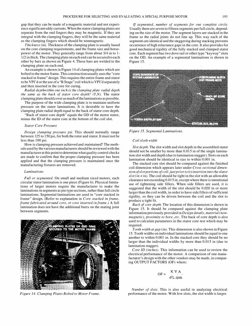
Number per phase, where axially and circumferentially located. It is suggested that six stator RTDs, two per phase, equally spaced circumferentially in the motor winding slots be purchased. Refer to Figure 29. The stator RTDs are inserted between the top and bottom coils of the stator . On short machines, they are generally at the machines' centerline or halfway between the bearings . On
198 PROCEEDINGS OF THE TWENTIETH TURBOMACHINERY SYMPOSIUM
Figure 29. RTD Leads in Stator.
Figure 30. Stator Coils Prior to Making Coil-to-Coil Connections.
Figure 31. Making Coil-to-Coil Connections.
longer machines, their axial position may be staggered, but should be located in the hottest region of the stator. The stator RTDs are thin elements composed of metallic wire wound non inductively to provide the proper resistance at a reference temperature (usually 32°F). Materials commonly used for the wire are copper, platinum, or nickel. This material must match the characteristic of the recording instruments. It is suggested that three wire detectors be employed to eliminate errors due to lead resistance.
Recommended alarm setting
Recommended shutdown setting. In accordance with NEMA, Class F insulation is rated for 105 °C rise by resistance. Most users specify Class F insulation but require that the motor must operate within Class B rise which is listed as 80°C by resistance. This practice has been in use for years, and is a way of building extra life into the insulation system. A general rule of thumb states that for
each additional! 0 degree rise in temperature the insulation life is reduced in half. This is the reason for being conservative on specifying the operating temperatures of motors. Vendors usually recommend setting the stator temperature alarms at the rated temperature rise. However, it should be based on an allowable increase in temperature above the actual running temperature rise.
Rotor Assembly
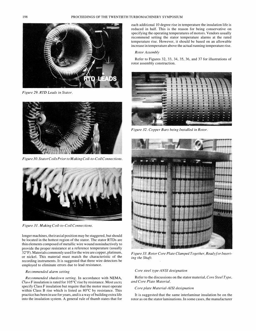
Refer to Figures 32, 33, 34, 35, 36, and 37 for illustrations of rotor assembly construction.
Figure 32. Copper Bars being Installed in Rotor.
Figure 33. Rotor Core Plate Clamped Together, Ready for Inserting the Shaft.
Core steel type-ANSI designation
Refer to the discussions on the stator material, Core Steel Type, and Core Plate Material.
Core plate Material-A/Sf designation
It is suggested that the same interlaminar insulation be on the rotor as on the stator laminations. In some cases, the manufacturer
PROCEDURE FOR SELECTING AND EVALUATING A SPECIAL PURPOSE MOTOR 199
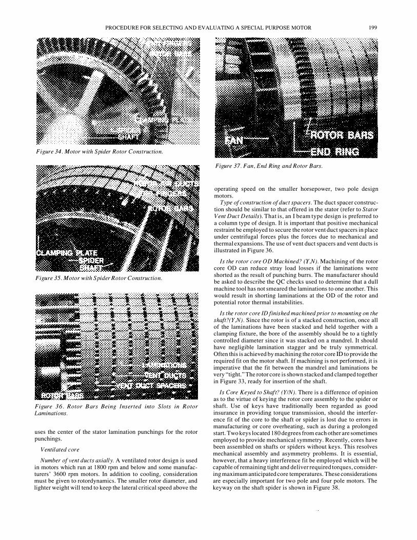
Figure 34. Motor with Spider Rotor Construction.
Figure 35. Motor with Spider Rotor Construction.
Figure 36. Rotor Bars Being Inserted into S lots in Rotor Laminations.
uses the center of the stator lamination punchings for the rotor punchings.
Ventilated core
Number of vent ducts axially. A ventilated rotor design is used in motors which run at 1800 rpm and below and some manufacturers' 3600 rpm motors. In addition to cooling, consideration must be given to rotordynamics. The smaller rotor diameter, and lighter weight will tend to keep the lateral critical speed above the
Figure 37. Fan , End Ring and Rotor Bars.
operating speed on the smaller horsepower, two pole design motors.
Type of construction of duct spacers. The duct spacer construction should be similar to that offered in the stator (refer to Stator Vent Duct Details). That is, an I beam type design is preferred to a column type of design. It is important that positive mechanical restraint be employed to secure the rotor vent duct spacers in place under centrifugal forces plus the forces due to mechanical and thermal expansions. The use of vent duct spacers and vent ducts is illustrated in Figure 36.
Is the rotor core OD Machined? (Y ,N). Machining of the rotor core OD can reduce stray load losses if the laminations were shorted as the result of punching burrs. The manufacturer should be asked to describe the QC checks used to determine that a dull machine tool has not smeared the laminations to one another. This would result in shorting laminations at the OD of the rotor and potential rotor thermal instabilities.
Is the rotor core ID finished machined prior to mounting on the shaft?(Y,N). Since the rotor is of a stacked construction, once all of the laminations have been stacked and held together with a clamping fixture, the bore of the assembly should be to a tightly controlled diameter since it was stacked on a mandrel. It should have negligible lamination stagger and be truly symmetrical. Often this is achieved by machining the rotor core ID to provide the required fit on the motor shaft. If machining is not performed, it is imperative that the fit between the mandrel and laminations be very "tight." The rotor core is shown stacked and clamped together in Figure 33, ready for insertion of the shaft.
Is Core Keyed to Shaft? (YIN). There is a difference of opinion as to the virtue of keying the rotor core assembly to the spider or shaft. Use of keys have traditionally been regarded as good insurance in providing torque transmission, should the interference fit of the core to the shaft or spider is lost due to errors in manufacturing or core overheating, such as during a prolonged start. Two keys located 180 degrees from each other are sometimes employed to provide mechanical symmetry. Recently, cores have been assembled on shafts or spiders without keys. This resolves mechanical assembly and asymmetry problems. It is essential, however, that a heavy interference fit be employed which will be capable of remaining tight and deliver required torques, considering maximum anticipated core temperatures. These considerations are especially important for two pole and four pole motors. The keyway on the shaft spider is shown in Figure 38.

200 PROCEEDINGS OF THE TWENTIETH TURBOMACHINERY SYMPOSIUM
Nominal Lamination Shrink Fit to Shaft or Spider (Mils/Inch Per Shaft Diameter)
Usually an acceptable value is 0.00075 in to 0.00 1 in interference fit per inch of shaft diameter.
Figure 38. Four Pole Motor Shaft with Six Spider Arms.
Maximum torque transmission capability of interference fit
The manufacturer should be queried to confirm that the torque transmission capability of the interference fit is sufficient for the five to eight times full load torque, or its amplified torsional value, which the motor can encounter during its first few cycles of inrush.
Core Clamping
Are end fingers and clamping plates integral or separate pieces? The core clamping plate on the rotor serves the same function as the end ring clamping plate on the stator. That is, it is used to compress (to approximately 100 psi) the rotor laminations. Refer to Figures 34 and 35, in which the rotor clamping plate and end fingers are illustrated.
The fingers on the clamping plate compress the laminations and prevent them from flaring. On the larger motors, the clamping plate and end fingers may be integral. On other motors, the clamping plate is separate from the fingers and the fingers are restrained against the centrifugal force by mechanical retainers or by spot welding to the end lamination. The fingers extend between the rotor bars and serve the same purpose as the fingers on the stator. Aluminum die cast rotor cages, employed on smaller and some less costly medium sized motors, count on the cast end ring, located up close to the core, as the core clamping mechanism in addition to being the current carrying end ring.
How is rotor core axially positioned and retained on the motor shaft? The core clamping plate is generally positioned on the shaft via a shoulder (Figures 34 and 35). An integral clamping plate usually is better than a two piece clamping plate.
ASTM designation of end fingers and clamping plate . These should be made of steel.
Thickness of end fingers and clamping plate . This can range from 1/4 in to 1- 1/2 in, depending on the motor size.
Radial distance from end fingers to OD of core in inches . The end fingers should extend almost to the OD of the rotor laminations to prevent flaring of the ends of the lamination as a result of the clamping pressure.
Is clamping plate or end fingers "dished" to maintain tooth clamping pressure? (Y,N). A dished clamping plate is superior to a flat clamping plate. The dish design is similar to that referenced in the stator clamping plate design.
Design Clamping Pressure (psi). The design clamping pressure is typically about 125 psi but should not be less than 100 psi.
How is pressure maintained? The clamping pressure is maintained by through bolts, or it is maintained by pressing the rotor laminations up against a shoulder in the shaft (Figure 34) and then positioning the clamping plate, usually with a split key.
Rotor Laminations
The data required by subparagraphs on Slot Geometry, Core ID, Core OD, Slot Depth, and Slot Width , cannot be compared between manufacturers. This information is needed to do an electrical design audit of the motor. The rotor bars may be tapered, teardrop, rectangular or other cross sections, depending on the torque and electrical requirements required by the driven equipment. Illustrations of rotor laminations are presented in Figures 8 and 9.
Core length (in). The core length should be a minimum to get the highest critical speed. A shorter core and larger diameter are generally preferred when considering the mechanical aspects. If one manufacturer employs vastly different proportions than the others, it should show up as a difference of the phrol (infinite support stiffness) critical speed.
Rotor Bars and End Rings
Material (ASTM No). lt is suggested that fabricated bar rotors be furnished with copper/copper alloy bars and end rings.
Bar extension from core to end ring (in). This extension length is critical to bar and end ring stress control, considering the full range of operating conditions. While a shorter bar extension may be better, often the longer extension can produce an overall preferred choice. All design and operation conditions must be evaluated. As the end ring expands due to centrifugal and thermal stresses, the greater the tendency for the bars or brazing to crack and the bar/end ring joint to fail.
Cross section dimensions of end ring (in x in). Many rotor failures typically occur at the rotor bar extension and end ring junction. It is suggested that a test be made to demonstrate that the rotor is designed to withstand a momentary overspeed without mechanical injury in accordance with MG 1-20.44 [5] which states that squirrel cage and wound rotor induction motors shall be so constructed that, in an emergency not to exceed one minute, they will withstand without mechanical injury overspeeds above synchronous speed in accordance with the following :
Synchronous Speed rpm
180 1 and over 1800 and below
Overspeed % of Synchronous Speed
20 25

PROCEDURE FOR SELECTING AND EVALUATING A SPECIAL PURPOSE MOTOR 20 1
The overspeeding also allows checking if the critical speed is in the overspeed region .
Brazing
· Materials (AWS No .) The bar shall be radially supported in the current carrying end ring and brazed into the ring with a phosphorous free brazing material. Butt type joints are not acceptable . Gas tungsten arc welding or full circle induction or gas brazing should also be required . The motor vendor should supply welding and brazing procedures for review and approval by the metallurgist to confirm that they are acceptable . Material and processes for attaching the bars to the end ring should be selected to minimize hydrogen embrittlement . When using stick electrodes, the weld rods have to be kept dry . Generally, they are kept in an oven until they are ready to be used . If they are not in the oven, the flux absorbs atmospheric moisture and, during the welding process, this water is decomposed into H2 and 02. The hydrogen gets into the weld and this results in hydrogen embrittlement . This problem does not exist if TIG welding is used. The welding procedures should, therefore, indicate what precautions the manufacturer uses to keep the weld rods dry until they are ready to be used .
· Procedure . In brazing the end ring to the rotor bars, the preferred method is induction brazing. This heats the entire end ring and all rotor bars evenly. The next most desirable method, is the multiple torch method whereby the rotor is set vertically on a heating table to which multiple gas torches are attached . The entire end ring and a ll rotor bars are heated at the joint from below. The least desirable is manual heating of the end ring and rotor bars by several people with torches .
Retaining Ring . Rotors for two and four pole motors require special design considerations . Medium sized motors may employ high strength alloy retaining rings . It is recommended that rotors for two and large four pole motors shall provided with shrunk-on stainless steel retaining rings. The purpose of the retaining rings is to provide for equal compressive and tensile stress of the end rings and to restrict rotor bar stresses to within a narrow range . Refer to Figure 39 in which the end ring is shown machined back, and the retaining ring is shown being slipped on .
· Material (ASTM No.). The end ring should be required to be nonmagnetic .
· Diametrical intnj'erence to end ring mils/inch ring cliameter. The retaining ring interference fit to the end ring is a design determined value, as described above . The manufacturer should be queried to determine their standard and confirm that this end ring remains tight under all conditions . The manufacturer should be queried as to determine what operating conditions are used to set the end ring shrink fit .
Bar/end ring joint stresses at
starting,
motor name plate conditions,
overspeed,
· Maximum allowable .
These numbers should be compared, as each manufacturer should be queried to determine the safety factor and that the allowable vs actual stresses are within the manufacturer 's own design guidelines .
Rotor Fans
Refer to Figures 37 and 38 in which various types of fans are illustrated .
R S F O R S Q U I R R H * C A G E M O T O R S
RETAINING RING
Figure 39. Rotors j(Jr Squirrel Cage Motors .
Material (ASTM No.)
Axial or Radial Flow. Axial flow fans are designed to handle larger flow volumes than radial centrifugal fans . The axial and combined flow fans direct air axially into the core end and into the air gap . They are also directional, so the fans must be exchanged end-for-end, if operation in the opposite direction is desired . Centrifugal fans may be either unidirectional or bidirectional, depending upon their design . There is no preference for an axial or radial flow fan . The blades on an axial flow fan, however, should not be in resonance within 15 percent of the operating speed. Campbell diagrams for the axial flow fan blading should be provided on very large motors . If the manufacturer can supply an installation list for machines using these same blades and blade height, then the requirement for Campbell diagrams might be waived .
Unidirectional or bidirectional. Fans which circulate air regardless of the motor rotation are bidirectional fans . Unidirectional fans depend upon the proper rotation of the motor . They c irculate air in only one direction .
How secured to shaft. Fans should be either integrally cast with the end rings (on small cast designs) or separately mounted . Separable fans should be permanently indexed angularly and axially . Fans with two pole motors should be shrunk on the shaft. A check for fan balance should be made by requiring that after final balance of the rotor, fans shall be installed and balanced . Corrections should be made on the fans only . Fans should be removed and reassembled on the assembly's residual unbalance, and phase

202 PROCEEDINGS OF THE TWENTIETH TURBOMACHINERY SYMPOSIUM
angle should not change. It i s, therefore, important that the fan be secured to the rotor end ring or spider using a rabbit or pilot fit positioned for accurate, repeatable positioning . The clearance in the bolt holes is insufficient to result in unrepeatable balancing once the fan has been removed. It is for this reason that a rabbit fit is required .
Flowrate (icfm)for each fan. A comparison of cfm between the vendors should be made. The manufacturer should be queried as to how it has been determined that the fans provide the flow and distribution of cooling air required.
Balance Provisions
Number of balance planes and locations. It is recommended that the manufacturer submit his balance procedures . Some motor manufacturers can balance the rotors at operating speed ( 1800 rpm or 3600 )rpm. Some balance machines read out unbalance as a bearing cap velocity in millimeters per second. They do not give rotor residual unbalance in gram-inches or ounce-inches as typical balance machines do . An ISO grade I , which is 1 .0 millimeter per second, where API 4W/N requirement is equivalent to approximately 0 .75 ISO or 3/4 of a millimeter per second.
Balance weight. Although most users require a balance tolerance of 4W/N, it is not uncommon to balance rotors to 1/4 of that value .
· Material (ASTM No.)
· How are balance weights secured in place?
Balance weights added to the rotor assembly (excluding fans and couplings) should be 300 stainless steel or an equivalent corrosion resistant material . Parent metal is to be drilled out in a banner which wil l maintain the structural integrity of the rotor and will not cause hot spots in operation . Chiseling, sawing, or torch burning should not be permitted under any circumstances . The use of solder or similar deposits for balancing purposes is not acceptable .
Shafts
Refer to Figure 38, which illustrates a four pole motors shaft with six spider arms submerged arc welded to the shaft, and a keyway in one of the spiders .
Shaft Material A/Sf No.
API requires that shafts be manufactured from one piece heat treated AISI 4 140 forged steel suitably ground . . . a shaft whose largest diameter is six inches or less may be machined from hot rolled steel, providing such bar stock meets all quality and heat treatment criteria established for shaft forgings . The diameter referenced should be the diameter of the rough shaft forging . The hot rolled steel criteria can be met only with rolling in accordance with aircraft quality bar stock .
Solid forging with or without spider. As previously indicated, a spider i s normally welded to the shaft on four pole motors . The spiders on four pole machines are generally welded to the shaft using a submerged arc procedure .
Material Yield Strength. It is suggested that the shaft be heat treated ANSI 4 140 forged steel . ANSI 4 140, depending on the tempering temperature, can have a yield strength from 95,000 psi with a tempering temperature of 1200°F to 238,000 with a temperature of 400°F. The mechanical properties of this steel are shown in Figures 40 and Figure 4 1 .
Shaft Stress a t Coupling (Allowable)
Steady State at Motor Nameplate Rating (psi)
Maximum transient during startup (psi). It is suggested that the shaft stresses be determined based on breakdown torque of the motor and the torsional analysis of the driven equipment
manufacturer . Fillet stress concentration factors should be taken into account .
API 67 1 [6] covers special purpose couplings for refinery services ; paragraph 2 . 1 . 1, states in part "the coupling and coupling juncture shall be capable of transmitting 1 15 percent of the purchaser' s specified maximum transient torque without damage." Induction motor drive shafting and couplings experience the maximum stress levels under two transient conditions . The first transient condition is called the initial torque burst and occurs during the first few seconds of rotation and i s caused by the initial current inrush. Depending on the stiffness of the electrical system, that i s, how much voltage drop occurs at the motor terminals during the initial start, the shaft end can be subject to between five to eight times full load torque . The second transient high stres s level i s during a motor pullout torque condition . For induction motors, this is approximately 225 percent of motor full load torque. For initial design considerations, the motor shaft end should be capable of withstanding a transient torque of approximately eight times full load torque . Fault conditions, such as a system short circuit also creates severe transient torques, especially on a phase to phase short ."
Shaft End Configuration (Tapered, Integral)
Integral flanges are more and more used so as to eliminate the grinding of a tapered fit on the shaft end and matching it to the coupling . Integral flange ends are also used to reduce overhung moments and, thus, help the critical speeds and rotor response of the equipment . As a result of the large torque requirements on a motor, the flange end may be fairly large . This may prevent the motor manufacturer from installing the cooling fan on the motor shaft . If this interference occurs, the integral shaft can be made in pieces .
Shaft Diameter (Inches)
At Bearing Journals
At core fit. Using the following formulas the approximate stres s levels a t the journal can be calculated .
HP = TN/63025
T = Torque (in-lbs)
N = operating speed in rpm
Ss = 16 x T/yield
The allowable stres s, Ss, is equal to the yield strength divided by 4. These calculations are without stress concentration factors . The same calculations can be obtained at the core fit .
Bearing Span (Inches)
Overall Length (Inches)
These two items can be compared between manufacturers to get an idea of the size of the motors offered .
End Brackets and B earing Housing
End Bracket or Pedestal Configuration
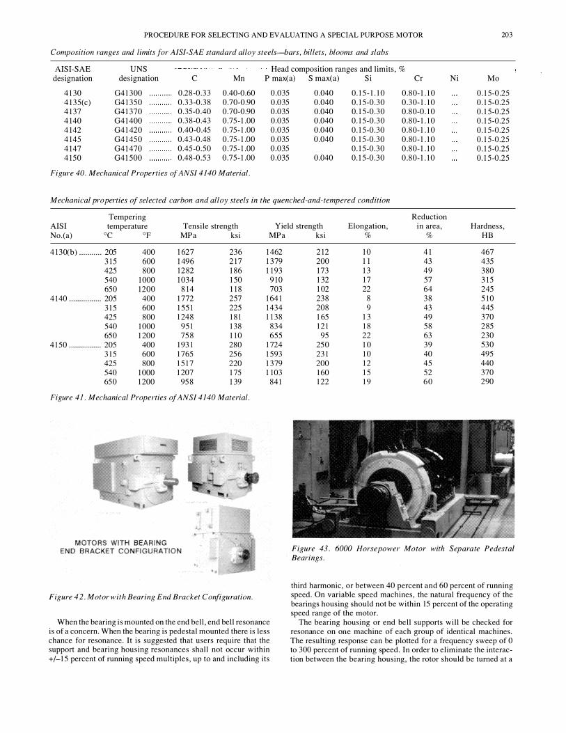
On an end bracket or end bell configuration, the bearing housing and its support structure is bolted to the machine frame . Refer to Figure 42. In order to position it radially, it is preferable to have this a rabbit fit and then, subsequently, dowelled and bolted . This configuration should also have its bearing centerline on the same vertical axis as the machine feet .
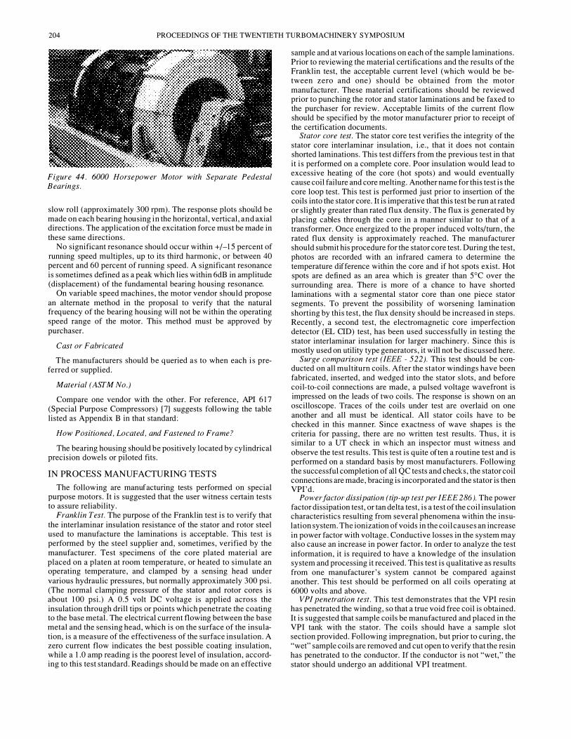
Pedestal bearing housings are separate from the machine frame and have their own mounting arrangements to the base . Refer to Figures 43 and 44 . This configuration is usually not widely used except on physically very large motors .
PROCEDURE FOR SELECTING AND EVALUATING A SPECIAL PURPOSE MOTOR 203
Composition ranges and limits for AISI-SAE standard alloy steels-bars, billets, blooms and slabs
AISI-SAE UNS Head composition ranges and limits, % designation designation c Mn P max( a) S max(a) Si Cr Ni Mo
4 130 04 1300 0.28-0.33 0.40-0.60 0.035 0.040 0. 15- 1. 10 0.80- 1. 10 0. 15-0.25 4 135(c) 04 1350 0.33-0.38 0.70-0.90 O.D35 0.040 0. 15-0.30 0.30- 1. 10 0. 15-0.25 4 137 04 1370 0.35-0.40 0.70-0.90 0.035 0.040 0. 15-0.30 0.80-0. 10 0. 15-0.25 4 140 04 1400 0.38-0.43 0.75- 1.00 0.035 0.040 0. 15-0.30 0.80- 1. 10 0. 15-0.25 4 142 04 1420 0.40-0.45 0.75- 1.00 0.035 0.040 0. 15-0.30 0.80- 1. 10 0. 15-0.25 4 145 04 1450 0.43-0.48 0.75- 1.00 0.035 0.040 0. 15-0.30 0.80- 1. 10 0. 15-0.25 4 147 04 1470 0.45-0.50 0.75- 1.00 0.035 0. 15-0.30 0.80- 1. 10 0. 15-0.25 4 150 04 1500 0.48-0.53 0.75- 1.00 0.035 0.040 0. 15-0.30 0.80- 1. 10 0. 15-0.25
Figure 40. Mechanical Prope rties of ANSI 41 40 Material.
Mechanical properties of selected carbon and alloy steels in the quenched-and-tempered condition
Tempering Reduction AISI temperature Tensile strength Yield strength Elongation, in area, Hardness, No. ( a) oc op MPa ksi
4 130(b) ........... 205 400 1627 236 3 15 600 1496 2 17 425 800 1282 186 540 1000 1034 150 650 1200 8 14 1 18
4 140 ................ 205 400 1772 257 3 15 600 155 1 225 425 800 1248 18 1 540 1000 95 1 138 650 1200 758 1 10
4 150 ................ 205 400 193 1 280 3 15 600 1765 256 425 800 15 17 220 540 1000 1207 175 650 1200 958 139
Figure 4I . Mechanical Properties of ANSI 41 40 Material.
MOTORS WITH BEARING END BRACKET CONFIGURATION
Figure 42. Motor with Bearing End Bracket Configuration.
MPa
1462 1379 1 193
9 10 703
164 1 1434 1 138 834 655
1724 1593 1379 1 103 84 1
When the bearing is mounted on the end bell, end bell resonance is of a concern. When the bearing is pedestal mounted there is less chance for resonance. It is suggested that users require that the support and bearing housing resonances shall not occur within +/-15 percent of running speed multiples, up to and including its
ksi % % HB
2 12 10 4 1 467 200 1 1 43 435 173 13 49 380 132 17 57 3 15 102 22 64 245 238 8 38 5 10 208 9 43 445 165 13 49 370 12 1 18 58 285 95 22 63 230
250 10 39 530 23 1 10 40 495 200 12 45 440 160 15 52 370 122 19 60 290
Figure 43 . 6000 Horsepower Motor with Separate Pedestal Bearings.
third harmonic, or between 40 percent and 60 percent of running speed. On variable speed machines, the natural frequency of the bearings housing should not be within 15 percent of the operating speed range of the motor.
The bearing housing or end bell supports will be checked for resonance on one machine of each group of identical machines. The resulting response can be plotted for a frequency sweep of 0 to 300 percent of running speed. In order to eliminate the interaction between the bearing housing, the rotor should be turned at a
204 PROCEEDINGS OF THE TWENTIETH TURBO MACHINERY SYMPOSIUM
Figure 44. 6000 Horsepower Motor with Separate Pedestal Bearings.
slow roll (approximately 300 rpm). The response plots should be made on each bearing housing in the horizontal, vertical, and axial directions. The application of the excitation force must be made in these same directions.
No significant resonance should occur within +/-15 percent of running speed multiples, up to its third harmonic, or between 40 percent and 60 percent of running speed. A significant resonance is sometimes defined as a peak which lies within 6dB in amplitude (displacement) of the fundamental bearing housing resonance.
On variable speed machines, the motor vendor should propose an alternate method in the proposal to verify that the natural frequency of the bearing housing will not be within the operating speed range of the motor. This method must be approved by purchaser.
Cast or Fabricated
The manufacturers should be queried as to when each is preferred or supplied.
Material (ASTM No.)
Compare one vendor with the other. For reference, API 6 17 (Special Purpose Compressors) [7] suggests following the table listed as Appendix B in that standard.
How Positioned, Located, and Fastened to Frame?
The bearing housing should be positively located by cylindrical precision dowels or piloted fits.
IN PROCESS MANUFACTURING TESTS
The following are manufacturing tests performed on special purpose motors. It is suggested that the user witness certain tests to assure reliability.
Franklin Test. The purpose of the Franklin test is to verify that the interlaminar insulation resistance of the stator and rotor steel used to manufacture the laminations is acceptable. This test is performed by the steel supplier and, sometimes, verified by the manufacturer. Test specimens of the core plated material are placed on a platen at room temperature, or heated to simulate an operating temperature, and clamped by a sensing head under various hydraulic pressures, but normally approximately 300 psi. (The normal clamping pressure of the stator and rotor cores is about 100 psi.) A 0.5 volt DC voltage is applied across the insulation through drill tips or points which penetrate the coating to the base metal. The electrical current flowing between the base metal and the sensing head, which is on the surface of the insulation, is a measure of the effectiveness of the surface insulation. A zero current flow indicates the best possible coating insulation, while a 1.0 amp reading is the poorest level of insulation, according to this test standard. Readings should be made on an effective
sample and at various locations on each of the sample laminations. Prior to reviewing the material certifications and the results of the Franklin test, the acceptable current level (which would be between zero and one) should be obtained from the motor manufacturer. These material certifications should be reviewed prior to punching the rotor and stator laminations and be faxed to the purchaser for review. Acceptable limits of the current flow should be specified by the motor manufacturer prior to receipt of the certification documents.
Stator core test. The stator core test verifies the integrity of the stator core interlaminar insulation, i.e., that it does not contain shorted laminations. This test differs from the previous test in that it is performed on a complete core. Poor insulation would lead to excessive heating of the core (hot spots) and would eventually cause coil failure and core melting. Another name for this test is the core loop test. This test is performed just prior to insertion of the coils into the stator core. It is imperative that this test be run at rated or slightly greater than rated flux density. The flux is generated by placing cables through the core in a manner similar to that of a transformer. Once energized to the proper induced volts/tum, the rated flux density is approximately reached. The manufacturer should submit his procedure for the stator core test. During the test, photos are recorded with an infrared camera to determine the temperature difference within the core and if hot spots exist. Hot spots are defined as an area which is greater than 5°C over the surrounding area. There is more of a chance to have shorted laminations with a segmental stator core than one piece stator segments. To prevent the possibility of worsening lamination shorting by this test, the flux density should be increased in steps. Recently, a second test, the electromagnetic core imperfection detector (EL CID) test, has been used successfully in testing the stator interlaminar insulation for larger machinery. Since this is mostly used on utility type generators, it will not be discussed here.
Surge comparison test (IEEE - 522). This test should be conducted on all multi turn coils. After the stator windings have been fabricated, inserted, and wedged into the stator slots, and before coil-to-coil connections are made, a pulsed voltage wavefront is impressed on the leads of two coils. The response is shown on an oscil loscope. Traces of the coils under test are overlaid on one another and all must be identical. All stator coils have to be checked in this manner. Since exactness of wave shapes is the criteria for passing, there are no written test results. Thus, it is similar to a UT check in which an inspector must witness and observe the test results. This test is quite often a routine test and is performed on a standard basis by most manufacturers. Following the successful completion of all QC tests and checks, the stator coil connections are made, bracing is incorporated and the stator is then VPI 'd.
Power factor dissipation (tip-up test per IEEE 286 ). The power factor dissipation test, or tan delta test, is a test of the coil insulation characteristics resulting from several phenomena within the insulation system. The ionization of voids in the coil causes an increase in power factor with voltage. Conductive losses in the system may also cause an increase in power factor. In order to analyze the test information, it is required to have a knowledge of the insulation system and processing it received. This test is qualitative as results from one manufacturer 's system cannot be compared against another. This test should be performed on all coils operating at 6000 volts and above.
VPI penetration test. This test demonstrates that the VPI resin has penetrated the winding, so that a true void free coil is obtained. It is suggested that sample coils be manufactured and placed in the VPI tank with the stator. The coils should have a sample slot section provided. Following impregnation, but prior to curing, the "wet" sample coils are removed and cut open to verify that the resin has penetrated to the conductor. If the conductor is not "wet," the stator should undergo an additional VPI treatment .

PROCEDURE FOR SELECTING AND EVALUATING A SPECIAL PURPOSE MOTOR 205
Immersion test (sealed winding conformance). The immersion test is performed when the stator has completed its specified amount of VPI cycles. This test is required in accordance with IEEE 429 [7] "Standard Test Procedures for the Evaluation of Sealed Insulation Systems for AC Electrical Machinery Implying Form Wound Stator Coils." The test should be tested in accordance with NEMA MG- 1-20.49. 1. A stator which cannot be submerged because of its size will be tested by a spray test in accordance with NEMA MG-2-20.49.2. 1-3.
Corona test. The standards for this test are not clearly defined. They extend from visually observing the energized stator in the dark, to picking up noise on an FM radio, to sophisticated recording of peaks and average levels of positive and negative voltage discharge pulses. The test is conducted when there are suspected corona problems, if a manufacturer is first being qualified, or where benchmark tests are needed.
Shaft ultrasonic testing. The rotor shaft should be manufactured from one piece heat treated AISI 4 140 forged steel. The shaft should be witnessed ultrasonic inspected prior to f inished machine. Ultrasonic inspection requires a witness point since there are no records of the UT test.
SUGGESTED INSPECTION POINTS
• The material certification for the core laminations of the rotor and stator should be reviewed. In addition, obtain the lamination thicknesses. A sample copy of the material certifications for the laminations should be obtained from the manufacturer during the bid review, so that any additional checks can be specified prior to placing the order for the motor.
• Review certifications of Franklin test obtaining acceptable l imits (zero be ing best, one being worse) from the motor manufacturer.
• Check that the punching burrs of the stator and rotor laminations are less than the permissible, preferably by optical inspection.
• Ask manufacturer to determine what type of quality control is used on welds holding the bars to the clamping plate. It appears that as a minimum they should be surfaced checked for cracks using liquid dye penetrant.
• A visual inspection of the rotor and stator prior to the VPI can be made. If a knife edge can be inserted between the laminations on either the stator or the rotor, insufficient clamping pressure is present.
• Review charts on VPI tank and oven charts to determine that the stator has undergone the proper VPI procedure. Review manufacturers standard quality control checks on their resins prior to insulation.
• Stator tests a) resin impregnations, b) surge comparisons, c) power factor dissipation test, d) immersion test, e) stator core test,and f) pre-VPI stator inspection.
• The stator core bore should be checked to confirm that it is concentric with the pilot fits on the frame that position the bearing housing. This should result in a concentric air gap. If the stator bore is not concentric with these piloted fits, it will not be concentric with the bearing and an uneven air gap will result.
• Inspect shaft laminations visually before the rotor is painted. This is done typically with a magnifying glass to confirm that none of the laminations have been shorted. After this inspection, the rotor is typically painted with an electrical grade varnish.
• Review with the motor manufacturer the quality control checks made of the brazed rotor bar to end ring joint. Confirm that no cracks exist and that a suitable fillet is present.
• There should be no change in core length before and after the core is mounted on the shaft. The axial dimensions of the rotor core
should be recorded at 90 degree intervals around the circumference of the rotor.
• Confirm that both fans are mounted with the proper rotation.
• The material certificates for the shafting should be reviewed and compared with that stated in the proposal. ANSI 4 140, depending on the tempering temperature, can have a yield strength from 95,000 psi with a tempering temperature of 1200°F up to 238,000 psi with a tempering temperature of 400°F.
APPENDIX
Technical Thbulation Inquiry No. : -------
Induction Motor Date:----------
Service : ______ _ Project: ---�-----
Manufacturer: ------ Thg No . : ---------
Location: --------
Guarantee Conditions Contractor: --------
Horsepower: ------ Phases---------
Speed: -------- Frequency: --------
Voltage : ------- Temperature Rise @ 40° C AMB _
I . Manufacturer 2. Place of Manufacture 3 . Motor Model Number 4. Guaranteed Efficiency at Normal Operating Point 5 . Enclosure Type -
A. TEWAC Enclosure (YIN) I) Top or bottom mounted coolers 2) How many coolers? 3 ) Tube design and material details 4) Water supply flowrate, pressure drop and
temperature (gpm, psi, 0F) 5) Allowable change in water flow, pressure
drop and temperature (gpm, psi, °F) maximum and ntinimum gpm.
6) Tube fouling factor used in cooler sizing 7) How long can motor run without one cooler? 8) At what horsepower can the motor run
continuously without one cooler? B. TEIGF Enclosure (YIN)
1) Acceptable leakage rate, scfm @ ___ psig 2) Type of shaft seals 3) Type of gas
6. Frame Construction A. Fabricated or Cast B. Material (ASTM No) C. Frame thickness (in . ) D . Core stacked i n frame, frame fabricated
around core or core inserted in frame. E. How is core centered and retained in frame? F. Air Baffle Material
7. Stator Core A. Core Steel Type - ASTMN Designation B. Core Plate Material
I) AISI Designation C5 or C6 2) Number of coats 3) Coated both sides? 4) Thickness of core plate insulation (in)
! . ___ _ 2. __ _ 3 . ___ _ 4. ___ _ 5 . ___ _ A. ___ _
1 . __ _ 2. __ _ 3 . __ _ 4. __ _
5 . __ _
6. __ _ 7 . __ _ 8. __ _
B . ___ _ !. __ _ 2. __ _ 3 .
6 . ___ _ A. ___ _ B . ___ _ c. ___ _ D. ___ _
E. ___ _ F. ___ _ 7. ___ _
A. ___ _ B . __ _
! . __ _ 2. __ _ 3. __ _ 4. __ _

206 PROCEEDINGS OF THE TWENTIETH TURBOMACHINERY SYMPOSIUM
D . Stator Vent Duct Details D. I) Number of vent ducts axially !. ___ I ) Number placed axially ! . ___ 2) Type of construction of duct spacer. 2. ___ 2) Cross section of duct spacer 2 . ___ D . Is rotor core O D machined? (YIN) D . 3) Avg and M a x psi loading on spacers 3. ___ E. Is rotor core ID fmish machined prior to E .
E . Stator End Fingers E. mounting on shaft? (YIN) I) Type material (ASTM No) 1 . ___ F Is core keyed to shaft (YIN) F.
2) Tapered or "kinked" to maintain pressure 2. ___ G. Nominal lamination shrink fit to shaft or G . o n tooth? (YIN) spider (mils/shaft dia)
3) Design details; material (nonmagnetic), 3 . ___ H. Maximum torque transmission capability of H . proximity t o bore , etc . interference fit. (ft-lb)
4) Integral with clamping plates? (YIN) 4. ___ I . Rotor Core Clamping I . F . Stator Clamping Plates F. I) Are end fingers and clamping plate I .
I ) Type material (ASTM No) 1 . ___ integral or separate pieces? 2) Thickness (in . ) 2 . ___ 2) How is rotor core axially positioned and 2. ___ 3) Radial Depth within I in, is the clamping 3. ___ retained on shaft?
plate radial depth the same as the back of 3) ASTM material designation of end fingers 3. ___ stator core depth? (YIN) and clamping plate
G . Stator Core Pressure G. 4) Thickness of end fingers and clamping 4. ___ I) Design Clamping Pressure ! . ___ plate (in, in) 2) How is clamping pressure achieved and 2. ___ 5) Radial distance from end fmgers to OD of 5. ___
maintained? core (in) H . Stator Laminations H . 6) Is clamping plate or end fingers "dished" 6. ___
1 ) Full or segmented 1 . ___ to maintain tooth clamping pressure (YIN) 2) If segmented, number of segments for one 2. ___ 7) Design clamping pressure (psi) 7. ___
complete "circle" 8) How is pressure maintained? 8. ___ 3) Slot width (in) 3 . ___ J . Rotor Laminations J .
4) Slot depth (in) 4. ___ I ) Slot Geometry !. ___ 5) Back of core depth (in) 5. ___ 2) Core ID (punching and finish dimensions) 2. ___ 6) Tooth width at gap (in) 6 . ___ (in, in) 7) Core ID (in) 7. ___ 3) Core OD (punching and finish 3. ___ 8) Number of slots 8. ___ dimensions) (in, in) 9) Skewed (YIN) 9. ___ 4) Slot depth (max) (in) 4 . ___
I . Peak Operating Flux Level (K lines/in) , stator I . 5) Slot width (max) (in) 5. ___ tooth minimum section and back of core 6) Number of slots 6. ___
J. Saturation level of core steel (K lines/in) J. 7) Core length (in) 7. ___ K . Stator Core Length K. K. Rotor Bars and End Rings K .
I ) Maximum/minimum core length for proposed ! . ___ I ) Material (ASTM No) ! . ___ frame (in) 2) Bar extension from core to end ring length 2. ___
2) Core length of proposed machined (in) 2 . ___ (in) 8. Stator Winding 8 . 3) Cross section dimensions o f end ring 3. ___
A. Insulation Class, VPI or B stage A. (in x in) B. Strand Insulation Details B . 4 ) Brazing 4. ___ C. Tum Insulation Details and RMS operating c. a) Materials (AWS No) a . ___
volts/tum b) Procedure b. ___ D. Groundwall Insulation D. 5) Retaining Ring 5. ___
I) Materials ! . ___ a) Material (ASTM No) a. ___ 2) Number of layers and tape thickness 2. ___ b) Diametral interference fit to end ring b. ___
a) Slot portion a . ___ (mils/in ring diameter) b) End winding and nose sections b . ___ 6) Bar/end ring joint stresses at 6. ___ c) Corona suppressant materials c. ___ a) Starting load a. ___
E. Stator Circuit E. b) Motor nameplate conditions b. ___ I) Number of strands per tum ! . ___ c) Overspeed c. ___ 2) Number of turns per coil 2. ___ d) Maximum allowable d. ___ 3) Number of circuits and type 3. ___ L. Rotor Fans L . 4) Number of separate cables per phase brought 4. ___ I) Material (ASTM No) !. ___
out from winding 2) Axial or radial flow 2. ___ a) Wire size a . ___ 3) Unidirectional or bidirectional 3. ___ b) Insulation b. ___ 4) How secured to shaft 4. ___
5) Cross sectional dimension of slot portion 5. ___ 5) Flow rate each fan (ICFM) 5. ___ of coil just prior to its insertion into slot 6) Normal range of cfmlkw 6. ___ (in x in) 7) Actual cfrnlkw 7. ___
6) Slot fillers used (YIN) 6 . ___ M. B alance Provisions M . F. Stator End Thrning Bracing F. I ) Number of balance planes and locations !. ___
1 ) Number of surge rings on OD of end turns I . 2) Balance Weight 2. ___ each end a) Material (ASTM No) a. ___ a) Material a. b) How secured in place? b. ___ b) Thickness (in) b . ___ 10 . Shaft 10 . c) Unsupported or supported to frame c. ___ A. Shaft material (ASTM No) A .
2) Coil-to-Coil Bracing 2. ___ B . Solid forging with or without spider B . a ) Material a. ___ C. Material yield stress (psi) c.
b) Compression and/or tension bracing b . ____ D. Shaft stress at coupling (allowable/actual) D . c) Number o f axial rows o n I D and O D of c. ___ I ) Motor nameplate rating (psi) I .
end turns 2) Transient during starting (psi) 2. ___ G. Stator Winding Temperature Dectors G. E . Shaft End configuration (tapered, integral) E .
I ) Type !. ___ F. Shaft diameter (in) F.
2) Number per phase , where axially and 2. ___ I ) At bearing journals I . circumferentially located 2) At core fit 2. ___
3) Recommend alarm set at °CI F 3. ___ G . Bearing span (in) G. 4. Recommend shutdown set at °CI F 4. ___ H. Overall length (in) H .
9. Rotor Assembly 9 . I I . End brackets and bearing housing I I . A . Core Steel Type - ASTM Designation A. A. End bracket or pedestal configuration A . B . Core plate Material - AISI Designation B . B . Cast o r fabricated B . C . Ventilated Core c. C. Material (ASTM No) c.

PROCEDURE FOR SELECTING AND EVALUATING A SPECIAL PURPOSE MOTOR 207
D. How positioned, located and fastened to frame?
1 2 . Radial Bearings A. TYJ>e - Sleeve or Pressure Dam
I) Provisions for alignment with shaft (how provided)
2) Backing material 3) Are bearings insulated? (YIN) 4) Insulation type 5) Loading (allowable/actual) (psi) 6) 'JYpe babbitt 7) Babbitt thickness
B. 'JYpe - Tilt Pad (YIN) I) Number of segments 2) Load on pad/between pad 3) Loading (allowble/actual) (psi) 4) Pivot (center, offset/percent) 5) Pad material 6) 'JYpe babbitt 7) Babbitt thickness 8) Axial tilt? (YIN) 9) Are bearing(s) insulated? (YIN)
10) Insulation type C. Temperature Detectors
1) 'JYpe (RTD or TCs) 2) Installation details 3) Maximum allowable operating temperature.
(C/F) D. Bearing-fit-to housing diametral dimension.
(mils loose or tigbt) E. Bearing-to-journal diametral clearance. (mils) F. Thrust Provisions? (YIN) G . Oil Seals
1) 'JYpe 2) Material
H. Gas Seals (for TEIGF Motors) I) 'JYpe 2) Material 3) Guaranteed Gas Leakage
1 3 . Lube Oil Requirements A. Self Lube (YIN)
I) Oil rings - How Many, Material (ASTM No) 2) Self oilers (YIN) 3) Oil type
B. Pressure Lube (YIN) I) Oil rings or other method for emergency
coastdown lubrication. (YIN) 2) Oil type (SSU @ .F) 3) Minimum oil pressure and flow rates
(psi , gpm) 4) Max oil inlet temperature (0F)
14. Vibration monitoring Equipment Manufacturer A. Access to probes during operation? (YIN) B. Probes mounted inbound or outbound of bearing
centerline C. Accelerometers mounted in which plane on
bearing housings 1 5 . Rotordynamics
A. Location of first lateral critical speed (rpm) B . Maximum amplification factor through critical
16 . Space Heater 'JYpe 17 . Noise Level Guarantee (dBA) 1 8 . Maximum Rotor End Float (in) 19 . Motor Space Requirements
Length/Width/Height 20 . Weights
D. __ _
12 . ___ _ A. __ _
1. __ _
2. __ _ 3 . __ _ 4. __ _ 5 . __ _ 6. __ _ 7 . __ _
B . ___ _ 1. __ _ 2. __ _ 3 . __ _ 4. __ _ 5 . __ _ 6. __ _ 7 . __ _ 8. __ _ 9. __ _
c. ___ _ 1. __ _ 2. __ _ 3 . __ _
D. __ _
E. ___ _ F. ___ _
G. __ _ 1. __ _ 2. __ _
H. __ _ 1. __ _ 2. __ _ 3 . __ _
1 3 . ___ _ A. ___ _
1. __ _ 2. __ _ 3 . __ _
B . ___ _ 1. __ _
2. __ _ 3. __ _
4. __ _ 14 . ___ _ A. ___ _ B . ___ _
c. ___ _
1 5 . ___ _ A. ___ _ B . ___ _ 16 . ___ _ 17 . ___ _ 1 8 . ___ _ 19 . ___ _
20 . ___ _
A. Rotor Weigbt (lb) B. Stator Frame Weight (lb) C. Cooler Weight (lb) D . Net Weight (lb) E . Shipping Weigbt (lb) F. Maximum Maintenance Weight (identify) (lb)
21. Electrical Performance Data A . Locked Rotor Code B . Locked Rotor Current (amps) and Torque (ft-lb)
1) Rated Voltage 2) 80 percent Voltage
C. Locked Rotor Power Factor D. Pull-Out Torque (ft-lb) E. Locked rotor withstand time-cold and hot (sec)
at 100 percent, 90 percent, 80 percent, volt. F. WK of motor rotor at motor speed (lb ft) G. Maximum allowable load WK during 80 percent
voltage start (lb ft) H. State allowable starting requirements I. Open circuit time constant (in seconds) J . X/R Ratio
22. Calculated Guarantee Efficiencies A. Full load B. Normal Operating Point C. % load D. Y2 load E. V• load
23 . Calculated Power Factor Corresponding to Item 22. A. Full load B. Normal Operating Point C. % load D. 1h load E. V• load
24. Test Facility A. Load testing method and capability B. Efficiency determination (IEEE Method) C. Vibration instrumentation available
REFERENCES
A. ___ _ B . ___ _ c. ___ _ D. __ _ E. ___ _ F. ___ _
2 1 . __ _ A. __ _ B . ___ _
1. __ _ 2. __ _
c. ___ _ D. ___ _ E. __ _
F. ___ _ G. __ _
H. ___ _ I. __ _ J. __ _
22. ___ _ A. ___ _ B . __ _ c. ___ _ D. ___ _ E. __ _
23 . ___ _ A. ___ _ B . __ _ c. __ _ D. ___ _ E. ___ _
24. __ _ A. ___ _ B . ___ _ c. __ _
1. Costello, M. J ., "Understanding The Vibration Forces In Induction Motors," Proceedings of the 1 9th Turbomachinery Symposium, Turbomachinery Laboratory, Department of Mechanical Engineering, Texas A&M University, College Station, Texas ( 1990).
2. "Form-Wound Squirrel Cage Induction Motors 250 Horsepower and Larger," 2nd Edition. API Standard 54 1.
3. Steel Products Manual, Electrical Steels, American Iron and Steel Institute, (January 1983).
4. " IEEE Guide for Testing Turn-to-Turn Insulation on Form-Wound Stator Coils for Alternating-Current Rotating Electric Machines-For Trial Use," IEEE Standard 522 ( 1977).
5. "Motors and Generators," NEMA MG 1 ( 1978).
6. "Special Purpose Couplings for Refinery Services," API Standard 67 1.
7. "Centrifugal Compressors for General Refinery Services," 4th Edition, API 6 17.

208 PROCEEDINGS OF THE TWENTIETH TURBO MACHINERY SYMPOSIUM