Procedure for Longworth Chuck constructiontnvalleywoodclub.org/articles/PDFs/Construction of a...
10
Procedure for Longworth Chuck construction Overall construction The Longworth chuck is composed of three major components. Connected to the lathe spindle is some device that fastens to the first of two disks called the base disk. The second disk we’ll call the face disk since that is the one we see as we look at the chuck from the turner’s perspective while turning. The two disks rotate relative to each other on their centers and have counter positioned spiral slots such that as the disks are rotated relative to one another they provide an opening between them where the spiral slots intersect. Grippers are attached through these openings so that as the disks are rotated relative to one another the grippers close on or open from the center of the disks. There are no inventions in this article. This construction procedure is based on a review of other articles on the subject. I picked up the methods of some directly (e.g. the disk marking process) but developed others to suit my own practices. I suggest that you read completely through this before starting and decide for yourself what parts work for you and what you may wish to change to better suit your individual practices. Leaving the grippers for the moment we can concentrate on three major components; the base disk, the face disk, and the means for connecting to the spindle. Let’s call the connecting means a spindle adapter – even though if may be a faceplate or some other device – for the rest of this document. Keep this in mind as you go through this procedure. It’s important to have a good reference point for the center. It’s a good idea to keep this in mind as you make each component. If at all possible keep a hole (just big enough to force a nail through it – be consistent with the nail size) in the center of these three components throughout the steps below. If you do this, you’ll be able to ensure alignment by putting a nail through the three holes. Locating the hole in the two disks is easy if you use a center jig for the band saw since they’ll have a hole in the middle for the pin. Wait until you have your spindle adapter on the lathe spindle and use the Jacob’s chuck in the tailstock to drill your pilot hole in the spindle adapter so that you know it’s concentric with the lathe spindle.
Transcript of Procedure for Longworth Chuck constructiontnvalleywoodclub.org/articles/PDFs/Construction of a...

Procedure for Longworth Chuck construction
Overall construction The Longworth chuck is composed of three major components. Connected to the lathe spindle is some
device that fastens to the first of two disks called the base disk. The second disk we’ll call the face disk
since that is the one we see as we look at the chuck from the turner’s perspective while turning. The
two disks rotate relative to each other on their centers and have counter positioned spiral slots such
that as the disks are rotated relative to one another they provide an opening between them where the
spiral slots intersect. Grippers are attached through these openings so that as the disks are rotated
relative to one another the grippers close on or open from the center of the disks.
There are no inventions in this article. This construction procedure is based on a review of other articles
on the subject. I picked up the methods of some directly (e.g. the disk marking process) but developed
others to suit my own practices. I suggest that you read completely through this before starting and
decide for yourself what parts work for you and what you may wish to change to better suit your
individual practices.
Leaving the grippers for the moment we can concentrate on three major components; the base disk, the
face disk, and the means for connecting to the spindle. Let’s call the connecting means a spindle
adapter – even though if may be a faceplate or some other device – for the rest of this document.
Keep this in mind as you go through this procedure. It’s important to have a good reference point for
the center. It’s a good idea to keep this in mind as you make each component. If at all possible keep a
hole (just big enough to force a nail through it – be consistent with the nail size) in the center of these
three components throughout the steps below. If you do this, you’ll be able to ensure alignment by
putting a nail through the three holes. Locating the hole in the two disks is easy if you use a center jig for
the band saw since they’ll have a hole in the middle for the pin. Wait until you have your spindle
adapter on the lathe spindle and use the Jacob’s chuck in the tailstock to drill your pilot hole in the
spindle adapter so that you know it’s concentric with the lathe spindle.

Figure 1 Major components: Spindle adapter, base disk, and face disk
The base disk is firmly fixed to spindle adapter and becomes a part of a subassembly that no more
operates separately. If a faceplate is chosen as a spindle adapter and is removed it must be carefully
replaced for use so that the original alignment is maintained. If at all possible the spindle adapter, be it
a faceplate or other means, should be permanently mounted on the base disk.
If you choose to use a faceplate, you may choose to attach it to the base disk and true the assembly
before doing the disk preparation which follows. That will require that you also align your face disk in
this way. If you do that make sure you do not mistake the center from the band sawing operation with
the center you make on the lathe.
Disk preparation Two disks are prepared by band sawing the two disks from flat sheet material. The base disk must be
rigid to carry the motion, without vibration or wobble, to the face disk and workpiece. The face disk
need not be as rigid but should be of substantial material to withstand movement of the screws that
connect the grippers through the face disk and the base disk without excessive wear. Band sawing the
disks using a centering jig will leave a clear hole at the center of the disk for later alignment.
The two disks are machined together and then separated and positioned so that the spiral slots in the
face disk spiral out and to the right and those on the base disk spiral out and to the left. Creating the
spirals is a critical step in construction since errors in their placement are transmitted directly to the
workpiece. It’s essential to ensure concentricity of the slots with the center axis of the lathe. To do so
means that you need to have a way to align the center of your spindle adapter and both disks before
attaching them. As previously noted, a small hole centered at the intended center of rotation is the best
way to accomplish that. Probably the best way to find the center of a disk is to use a circle cutter on the

band saw while cutting the disk from sheet stock in the first place. The pin hole used in that process is,
by definition, the center of the disk; and a disk cut this way will run true on the lathe if the spindle
adapter is also aligned true.
To make the required marks for cutting the spiral slots in the disks:
1. Draw a diagonal across the face disk. Make sure that all of your diagonals cross exactly the
center of the disk.
2. Using a drafting triangle and straight edge, draw another diagonal perpendicular to the first;
crossing exactly at the center.
3. Using a protractor or 45 degree drafting triangle, draw a diagonal at 45 degrees with either of
the previous diagonals.
4. Using the drafting triangle, draw a fourth diagonal 90 degrees from your previous one.
Note: You should now have eight equal segments on the face disk.
Figure 2 Eight segments
5. Draw the first circle on the face disk about 1/2” from the outside edge of spindle adapter.
Exactly where this circle is placed isn’t critical but will affect the rest of the circles and thus the
spiral slots. Keep in mind that the wing nuts will need to clear the spindle adapter to tighten
the grippers.
6. Draw the second circle about 1/2" to 3/4" (depending on disk size) from the outside of the disk.
7. Draw the third circle about halfway between the first and second circle.
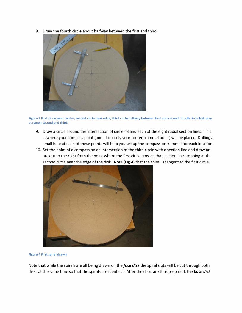
8. Draw the fourth circle about halfway between the first and third.
Figure 3 First circle near center; second circle near edge; third circle halfway between first and second; fourth circle half way between second and third.
9. Draw a circle around the intersection of circle #3 and each of the eight radial section lines. This
is where your compass point (and ultimately your router trammel point) will be placed. Drilling a
small hole at each of these points will help you set up the compass or trammel for each location.
10. Set the point of a compass on an intersection of the third circle with a section line and draw an
arc out to the right from the point where the first circle crosses that section line stopping at the
second circle near the edge of the disk. Note (Fig.4) that the spiral is tangent to the first circle.
Figure 4 First spiral drawn
Note that while the spirals are all being drawn on the face disk the spiral slots will be cut through both
disks at the same time so that the spirals are identical. After the disks are thus prepared, the base disk

will be flipped over so that the slots will spiral out the opposite direction thus leaving a nominally square
opening through which the gripper bolts will pass.
11. Look carefully at how close that arc comes to the intersection at which the point of your compass (and ultimately your trammel point) will go on adjacent arcs. Take into account the diameter of the router bit you’ll be using and decide if that point will be too close to the spiral slot you’ll be cutting. If it’s too close to ensure that you’ll have a good purchase for the router trammel point you’ll need to change one of the parameters to move it away. You can resolve to change the length of the router trammel so that it will cut above or below the spiral line (away from the intersections) or increase the size of circle #1 (effectively the same thing). Once you have decided on a course of action, remove the spiral line and redraw it as necessary.
12. Repeat this four times, each time skipping one section line. You should now have 4 spirals separated by 90 degrees between the first and second circles.
Figure 5 First 4 spirals
Note: The end of the spirals nearest the center need not go all the way to the first circle, but where they end will determine the smallest bowl that can be gripped with these grippers.
13. Set the point of the compass on an intersection of the third circle with a section line 45 degrees
from the first set of four spirals and draw an arc out to the right from the point where the fourth
circle crosses that section line stopping at the second circle near the edge of the disk.
Note: It’s important that enough material be left between the first set of four spirals and
this set of four so that the disks retain strength in this area. Stopping at the fourth circle will
ensure enough separation but will increase the size of the smallest bowl possible. If you
need to turn a smaller bowl, you can remove four of the grippers and hold the smaller bowl
with just four grippers.
14. Repeat the above three more times to get four new curves 45 degrees removed from the first
four.

Figure 6 All 8 spirals. Note that the second half don't go all the way into the middle circle
15. The disks should now be connected firmly together. Before making any firm connections ensure
that the centers of the disks are aligned by inserting a nail through the pilot holes in the center.
One way to attach the disks is to put three screws through the face disk into the base disk
approximately 120 degrees separated around the outer edge but located so as not to interfere
with the following operations. Note: These screws may need to be removed to enable swinging
the router trammel, but make sure you remove only one of the screws at a time, replacing it
when the clearance is no longer needed. In other words: Keep at least 2 screws engaged at all
times to ensure that the disks do not rotate relative to one another.
16. Once the disks are fastened together it’s time to route the slots. The router should have a
trammel base plate. Just as you did to draw the spiral, adjust the trammel radius so that the
distance from the trammel pin matches the distance from the intersection of the third circle
with one of the section lines to the spiral line you drew in a previous step. Check that the router
bit follows your drawn arc.
17. Clearly mark the center points for the trammel. A small hole at each of these points will help
you set up the trammel for each location. If you haven’t already drilled these holes do it now.
Set the pin of the trammel into the hole you’ve drilled, tap it with a hammer, and swing the
router around that point.
18. Plunge the router bit partially into the disk at the centermost point of the spiral and swing out
until the bit comes to the outermost circle. Continue plunging the router until both disks are
completely cut.
19. Repeat the above for all of the required grooves. Make sure you start the slots where you
marked the spirals.
Finish the disks appropriately. The face disk needs to turn relative to the base disk smoothly and as it
turns, the grippers need to expand or contract smoothly relative to the center. A soft granular surface
or edge isn’t likely to produce smooth turning or stand up to repeated use. Slots must be sanded
smooth and finished with a durable product such as shellac that will reinforce the edges and internal
surfaces.

Your Spindle Adapter The spindle adapter is simply the piece that attaches the lathe spindle to the base disk of the Longworth
chuck. You can use a regular face plate that fits you lathe, a disk made from durable materials that you
grip in a four jaw chuck, or a threaded block you make. Make sure that when the spindle adapter is
attached to the base disk the slots spiral out to the left when facing the chuck from the tailstock end.
Using a faceplate
The most critical issue with using a standard faceplate is that it must be very well aligned with the base
disk. To do that can be difficult. If you’ve made your disks already and now need to center your
faceplate, you can do the following:
1. Secure piece of hardwood to the faceplate.
2. Install the faceplate on the lathe and turn the hardwood true making sure its face is flat.
3. Using a Jacobs Chuck in the tail stock, drill a small hole in the center of the hardwood piece.
Plan the diameter of this hole to tightly fit a nail that you’ll use in the following steps.
4. Leaving the hardwood attached to the faceplate, apply glue to the face of the hardwood disk.
5. Put a nail through the center hole of the base disk and through the hardwood to hold them on
center and press them together by bringing up the tailstock (remove live center) and clamping
the assembly together firmly.
Note: Surfaces of the base disk and the hardwood piece must be flat, true, and clean. It may be wise to
drive screws through the base disk into the hardwood block as additional security.
Using a durable disk gripped in a four jaw chuck
The means for attaching a disk involves a similar process as that for a faceplate but doesn’t necessarily
require a hardwood piece. Follow this procedure:
1. Install your disk into the scroll chuck. You may need to use spacers under the disk to get it flush
with the outer face of the chuck’s jaws and turning true.
2. Drill a small hole in the center of your disk using a bit in a Jacobs chuck in the tail stock.
3. Follow the above technique to keep the disk aligned while attaching it to the base disk.
Using a threaded block
Make your block long enough to accommodate the depth of the spindle and the screws needed to
attach it to the base disk. After the threads are cut into the block and the block is shaped on the lathe,
drill a small hole in the spindle adapter with a Jacobs chuck in the tail stock to use for alignment with the
base disk.
The Grippers Grippers need to be strong but malleable so they grip the workpiece without damaging it. My choice for
this project was #5 stoppers with a 3/16” hole from a specialty company. The dimensions are:

Top Diameter: 1-1/16"
Bottom Diameter: 7/8"
Length: 1"
Hole Diameter: 3/16"
The 3/16” hole would clear a 10-24 bolt but that bolt would be loose in the 1/4" square hole left by the
crossing 1/4” spiral slots. So I used 1/4” – 20 bolts drilling the stoppers with a 5/16” drill bit. The hole
was enlarged enough to let the 1/4” bolts pass through with little difficulty and be held loosely by the
rubber stopper which closed up a bit after the drilling operation. As it turns out, the 1/4” bolts work
very well in the slots.
Figure 7 Gripper assembly with stopper; 1/4" screw; wing nuts; fender washers; and 1/4" flat washer The machine screws need to be about 1/2" longer than the thickness of the disk sandwich so that the
wing nuts won’t un-screw and fall off during adjustment of the chuck.
Drilling of the stoppers presented no problem. I used an 3/4" MDF jig which was simply a flat board
with eight 1” hole drilled with a Forstner bit. Eight stoppers at a time were pressed into the holes, the
board with stoppers was placed on the drill press table upside down (wide part of stoppers down) and a
5/16” bit passed through each a few passes. The whole operation took less than five minutes.
Figure 8 Stopper drilling jig

The 1/4” bolts are then passed through a flat washer, the stopper, and a fender washer. The assembled
parts then pass through the disks and a second fender washer is added before the wing nut.
Assembly of the spindle adapter and the base disk Regardless of your choice of spindle adapter it’s imperative that the spindle adapter be centered exactly
as possible with the base disk. Using the holes drilled into the center of each of the three major
components as the alignment mechanism helps to ensure co-axial alignment.
Once the disks are aligned using a nail through the hole previously drilled into the center of the two
disks and the spindle adapter it’s time to permanently attach the two disks together.
Clamp the two disks together securely. Use at least 3 of the grippers through the holes of the two disks
to immobilize the disks relative to each other. With this done, you can remove the nail and secure the
two disks with screws and washers appropriate to connecting them is a way that the face disk freely
rotates relative to the base disk.
While this could be done with a wood screw, I suggest drilling and tapping a hole to accommodate a
substantial machine screw. Ideally, the screw would go through the base disk and thread into the
spindle adapter. A washer between the head of the screw and the face disk would provide a bearing
for assembly. In my case, I used a nylon flat washer, a steel flat washer, and a 1/4” screw.
The screw should be secure but not so tight as to restrict the face disk rotation. If the screw is loose to
the extent that it doesn’t hold fast through repeated rotations of the face disk, remove the screw; put a
little CA glue on the threads (be careful not to get it on the hole in the face disk) and screw it back in.
Figure 9 Finished Longworth chuck set for 7" bowl. Note the center screw and washer combination
Using the Longworth Chuck The Longworth chuck is a convenient mechanism to hold a turning to do operations in an area that
otherwise may not be accessible; for example: the base of a bowl. The temptation is to make your
chuck as large as your lathe will handle – in my case, my chuck is 19 1/2" in diameter – and that may not
be consistent with the physics of the situation. A bowl that would require that large a diameter chuck
would be pretty heavy and could have the center of its mass quite a distance back from the face of the
chuck thus precipitating a pretty hazardous condition if it should get loose.
So using the chuck requires some precaution. There are three things that will add safety to the
operation of the chuck:
1. Keep the speed low. A general rule of thumb for turning bowls is to set your speed so that the
outer circumference of the piece does not exceed 27 feet per second. The edge speed of a 20”
disk at 300 RPM is 26 feet per second. In contrast to that, a 12” disk at 500 RPM is just 26 feet
per second. Be aware of the size and weight distribution of your workpiece and set your speeds
accordingly. To quickly calculate the lathe speed, divide 6000 by the diameter of the work; for
example: a 12” workpiece would be 500 RPM – [6000/12 = 500].
2. Always bring the tailstock up to press the workpiece to the Longworth chuck. This takes a bit of
planning to leave a nub on the base or to have some other means of contact between the live
center and the bowl. Keep the tailstock in place as long as possible while dressing the area and
check the hold of the chuck when you must remove the tailstock to finish up.
3. Plan your work so that you can finish off the area with light cuts. Avoid cuts that could dig in
and yank the workpiece out of the chuck.
Summary This procedure isn’t the only one and maybe not the best one. If you followed the advice in the
beginning of this article you’ve arrived here before committing to the procedure yourself. If anything in
the procedure doesn’t suit your work habits, I encourage you to note the change and share it with the
rest of us. We’re here to learn after all.
If you have questions send me an email at [email protected] and/or post it on the forum; and
Good Luck!