RAPID MACROCELL TESTS OF ASTM A775, A615, and A1035 REINFORCING BARS

FSEL PROCEDURE FOR
INSTALLATION OF STRAIN GAGES ON REINFORCING BARS
Rev. 0 1
1. PROCEDURE OVERVIEW
This procedure is to be used for installation of bonded strain gages on reinforcing bars. It includes necessary materials and a recommended practice for surface preparation, installation, and protection of strain gages.
Actual installation of the strain gage itself is a relatively minor portion of this procedure. The majority of this procedure is related to waterproofing and mechanical protection of the gage. These items are needed to ensure the gage will survive the concrete casting process.
1.1. Student Responsibilities:
• Read and understand the requirements of this procedure • Provide reinforcing bars for instrumentation • Acquire all materials for strain gage installation
1.2. Staff Responsibilities:
• Read and understand the requirements of this procedure • Assist students with installation as needed
2. EQUIPMENT AND TOOLS
There are two primary suppliers for strain gages at FSEL: Texas Measurements (http://www.straingage.com/) and Micro Measurements (http://www.vishaypg.com/micro-measurements/). Texas Measurements is an importer of gages manufactured by Tokyo Sokki Kenkyujo (http://www.tml.jp/e/).
Lead times for purchasing gages vary wildly. Occasionally gages are in stock in the U.S. and can be shipped right away. Often gages are not in stock and occasionally gages must be sent from Japan to local suppliers. In that case, lead times can be 2 to 3 months. Historically, Micro Measurements has had a longer lead-time than Texas Measurements. It is recommended that the supplier be contacted prior to ordering to get estimated lead times.
2.1. Gages Purchased from Texas Measurements
The typical gage for reinforcing bars is FLA-5-11-5LT. This gage is a 5-mm, 120 Ω general purpose, uniaxial gage that is temperature compensated for mild steel. It has a pre-attached 3-lead wire that is 5 m long. An alternative gage that is commonly used is FLA-6-350-11-3LT.

FSEL PROCEDURE FOR
INSTALLATION OF STRAIN GAGES ON REINFORCING BARS
Rev. 0 2
This gage is similar to the previous gage but has a longer gage length of 6 mm and a resistance of 350Ω.
2.2. Gages Purchased from Micro Measurements Strain Gages
The typical gage for reinforcing bars is C2A-06-250LW-350. This gage is very similar to the FLA-6-350-11-3LT gages described in the previous section.
2.3. Materials from Texas Measurements
▪ CN adhesive ▪ SB Tape ▪ VM tape
▪ Epoxy overcoat (Hardman Epoweld 8173, Part A & Part B)
2.4. Materials from Micro-Measurements
▪ M-Coat A ▪ Gage Installation Tape (PCT 2M)
2.5. Materials Generally Available at FSEL
▪ Pneumatic Angle die grinder ▪ Fine Sanding Disc ▪ Coarse Sanding Disc
▪ Non-Woven Sponges ▪ Razor Blade or Utility Knife ▪ Digital Multimeter
▪ Electrical tape ▪ Zip ties
2.6. Additional Materials
▪ Acetone
3. PERSONAL PROTECTIVE EQUIPMENT
▪ Safety glasses ▪ Safety shoes ▪ Dust Mask ▪ Rubber gloves
4. DETAILED PROCEDURE
4.1. Mark the area of the bar to be gaged.
Typically, an area about 1 in. long is sufficient for gage installation. Avoid placing a gage directly on a longitudinal rib because it would require removing a considerable portion of the rebar cross section.
4.2. Grind the bar surface

FSEL PROCEDURE FOR
INSTALLATION OF STRAIN GAGES ON REINFORCING BARS
Rev. 0 3
4.2.1. Using a coarse sanding disc on a pneumatic angle die grinder, begin smoothing the bar surface.
Typically, the strain gage installation area will be longer than the transverse rib spacing of the bar. Use the coarse sanding disc to remove the transverse ribs and make the bar surface smooth. Excessive grinding of the bar, i.e. to the extent that the resulting surface is flat instead of round surface, should be avoided.
4.2.2. Using a fine sanding disc on a pneumatic angle die grinder, complete smoothing the bar surface.
The finished surface should be smooth, shiny, and free of grinding marks, as shown in Figure 1.
Figure 1 – Photograph of bar after grinding
4.3. Clean the bar surface using acetone and non-woven sponges.
Wet the sponge thoroughly with acetone and wipe across the polished area of the bar. Repeat the process with fresh sponges and wiping in one direction until the non-woven sponge remains white after wiping. Be careful not to wipe the sponges through a dirty un-polished area into the clean, polished area as shown in Figure 2.
Note that acetone is a highly flammable material and should be handled accordingly. Wear safety glasses to protect your eyes from acetone. Long-term exposure to acetone vapors is harmful and at a minimum, can cause headache and dizziness. Use acetone in a properly ventilated area and avoid breathing in acetone vapors.

FSEL PROCEDURE FOR
INSTALLATION OF STRAIN GAGES ON REINFORCING BARS
Rev. 0 4
Figure 2 – Wiping the clean area
4.4. Mark the gage location.
Mark the final gage location with a pencil or marker. The mark should be adjacent to the freshly cleaned area, i.e. not in the gage installation region, to avoid contamination.
4.5. Attach the strain gage.
For satisfactory bonding of the gage to the bar, it is essential that the bar surface be completely clean prior to gage installation. If there is a delay between surface preparation steps described above and the gage installation, carefully inspect the surface, and repeat the cleaning steps as needed. Re-applying acetone is highly recommended to remove the collected dust on the surface. Using the fine sanding disc might also be needed for delays that are longer than 1 to 2 days.
Attaching the gage consists of a number of smaller steps. These steps need to be done quickly and smoothly to ensure a reliable bond between the gage and the substrate.
4.5.1. Identify the top and bottom surfaces of the strain gage before removing it from the protective sleeve.
The “top” of the strain gage has the visible metallic wires printed on it. The “top” of the gage will also have the lead wires attached to it; these can be seen in Figure 3. The printed wires are visible from the “bottom,” but they will be dull in color.
Do not touch the bottom surface of the strain gage, as it would contaminate the bonding surface.

FSEL PROCEDURE FOR
INSTALLATION OF STRAIN GAGES ON REINFORCING BARS
Rev. 0 5
Figure 3 – Identifying the top of the gage
4.5.2. Remove the gage from the protective plastic and apply a piece of gage installation tape to the top of the gage without touching the bottom of the gage.
The tape serves two purposes: 1) it allows handling of the gage without touching it and 2) it helps position the gage on the specimen for bonding. The piece of tape should be 2 to 3 in. long with the gage centered in the strip of tape, as shown in Figure 4.
The gage can be temporarily placed on a clean glass surface to apply the tape. If this technique is used, the glass surface needs to be completely cleaned before placing each gage, preferably using acetone.
Figure 4 – Applying tape to the gage
Top Surface Bottom Surface

FSEL PROCEDURE FOR
INSTALLATION OF STRAIN GAGES ON REINFORCING BARS
Rev. 0 6
4.5.3. Position and tape the gage on the bar.
Using the tape to handle the gage, position the gage over the ground and cleaned area of the reinforcing bar. Press the tape to the bar to temporarily hold the gage in place as shown in Figure 5. Inspect the position of the gage. If repositioning after pressing the tape is needed, make sure the area to be covered by the strain gage is not contaminated by the residue from the tape. Use acetone and non-woven sponge as needed to ensure a clean surface.
Figure 5 – Strain gage held in position with tape
4.5.4. Partially peal back the tape to expose the bottom surface of the gage.
Starting with the end of the tape near the strain gage lead wires, slowly peel the tape from the bar. Stop peeling the tape once the complete gage is expose. The portion of the tape beyond the gage should be left adhered to the bar to allow the gage to be returned to its previous location as shown in Figure 6.
FSEL PROCEDURE FOR
INSTALLATION OF STRAIN GAGES ON REINFORCING BARS
Rev. 0 7
Figure 6 – Strain gage and tape peeled back for gluing
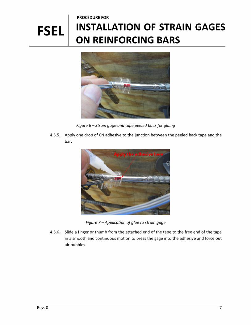
4.5.5. Apply one drop of CN adhesive to the junction between the peeled back tape and the bar.
Figure 7 – Application of glue to strain gage
4.5.6. Slide a finger or thumb from the attached end of the tape to the free end of the tape in a smooth and continuous motion to press the gage into the adhesive and force out air bubbles.
Apply the adhesive here

FSEL PROCEDURE FOR
INSTALLATION OF STRAIN GAGES ON REINFORCING BARS
Rev. 0 8
Figure 8 – Pressure applied to strain gage and adhesive
4.5.7. Maintain pressure on the tape and gage for approximately 1 minute to allow the adhesive to set and harden.
Adhesive drying times are affected by ambient temperature and humidity.
4.5.8. Carefully remove the tape from the gage and bar.
Peel back the tape from the end of the gage opposite the lead wires. The tape must be peeled back slowly, carefully, and as horizontally as possible to avoid damaging the gage or lead wires.
4.5.9. After removing the tape, inspect the gage for unbonded areas.
Unbonded areas will appear as air bubbles or areas of a slightly different color than the bonded areas. If the unbonded areas are on the edges of the gage, more adhesive can be added. If more adhesive is added, reapply pressure to allow the adhesive to cure.
FSEL PROCEDURE FOR
INSTALLATION OF STRAIN GAGES ON REINFORCING BARS
Rev. 0 9
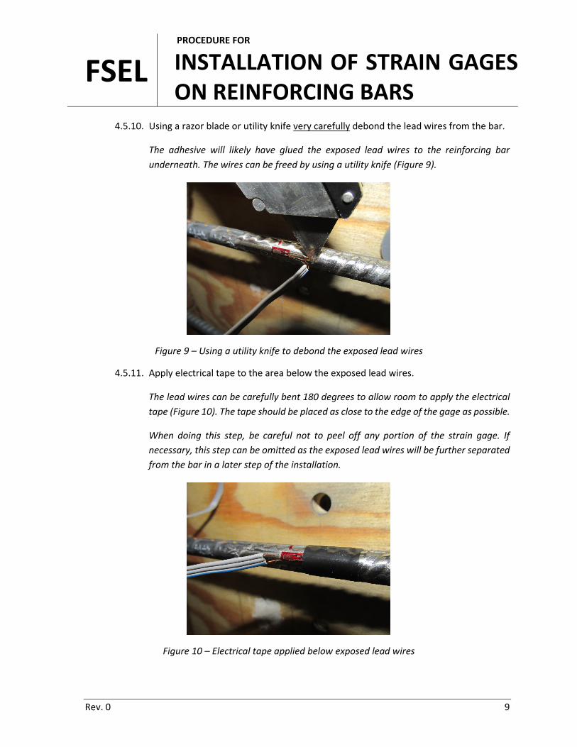
4.5.10. Using a razor blade or utility knife very carefully debond the lead wires from the bar.
The adhesive will likely have glued the exposed lead wires to the reinforcing bar underneath. The wires can be freed by using a utility knife (Figure 9).
Figure 9 – Using a utility knife to debond the exposed lead wires
4.5.11. Apply electrical tape to the area below the exposed lead wires.
The lead wires can be carefully bent 180 degrees to allow room to apply the electrical tape (Figure 10). The tape should be placed as close to the edge of the gage as possible.
When doing this step, be careful not to peel off any portion of the strain gage. If necessary, this step can be omitted as the exposed lead wires will be further separated from the bar in a later step of the installation.
Figure 10 – Electrical tape applied below exposed lead wires

FSEL PROCEDURE FOR
INSTALLATION OF STRAIN GAGES ON REINFORCING BARS
Rev. 0 10
4.6. Apply waterproofing and mechanical protection to the gage.
Since the gage and bar will be placed in fresh concrete and that concrete will be consolidated with vibration, the gage will need both waterproofing and mechanical protection.
4.6.1. Apply coating(s) of M-Coat A to the strain gage, exposed lead wires, and surrounding area.
Apply a thin coat of M-Coat A using the brush provided (Figure 11). Allow 10 to 15 minutes for the coating to dry. It is recommended that three layers of M-Coat be used for each strain gage. Each coating layer needs to dry before applying the next layer.
Figure 11 – Application of M-Coat A to exposed lead wires
4.6.2. Cut a strip of SB tape long enough to cover the entire strain gage.
4.6.3. Completely cover the gage with SB tape, peel off the paper backing.

FSEL PROCEDURE FOR
INSTALLATION OF STRAIN GAGES ON REINFORCING BARS
Rev. 0 11
4.6.4. Press the SB tape onto the bar making sure to seal the SB tape to the bar.
Figure 12 – Strain gage and bar covered in SB tape
4.6.5. Fold the exposed lead wired on top of the layer of SB tape applied in Article 4.6.4 and lightly press the wires into the SB tape.
In this step, the lead wires should be bent 180 degrees from their original direction before embedding in the SB tape (Figure 13).
Figure 13 – Exposed lead wired bent onto SB tape layer

FSEL PROCEDURE FOR
INSTALLATION OF STRAIN GAGES ON REINFORCING BARS
Rev. 0 12
4.6.6. Place another small piece of SB tape on top of the exposed lead wires to encapsulate them.
The bare lead wire should be completely encapsulated in SB tape. Only the insulated portion of wire should be visible after this step (Figure 14).
Figure 14 – Lead wire encapsulated in SB tape
4.6.7. Completely cover the SB tape with a single wrap of VM tape.
Figure 15 – Strain gage and bar covered in VM tape

FSEL PROCEDURE FOR
INSTALLATION OF STRAIN GAGES ON REINFORCING BARS
Rev. 0 13
4.6.8. Wrap the VM tape with electrical tape.
Figure 16 – Strain gage and bar covered with electrical tape
4.6.9. Mix a small amount of epoxy overcoat (Hardman Epoweld 8173) per the directions provided on the bottle.
4.6.10. Coat the entire strain gage area as defined by the electrical tape with a thin layer of epoxy and allow the epoxy to set and cure.
This epoxy forms a hard layer that improves mechanical protection of the gage during concrete casting.
4.7. Wire protection.
The wires also need mechanical protection in case the wire is pulled during concrete casting.
4.7.1. Using a zip tie, tightly attach the wire to the bar at the location where it exits the layer of epoxy.
4.7.2. Make a small loop in the lead wire by wrapping it ground a finger.
FSEL PROCEDURE FOR
INSTALLATION OF STRAIN GAGES ON REINFORCING BARS
Rev. 0 14
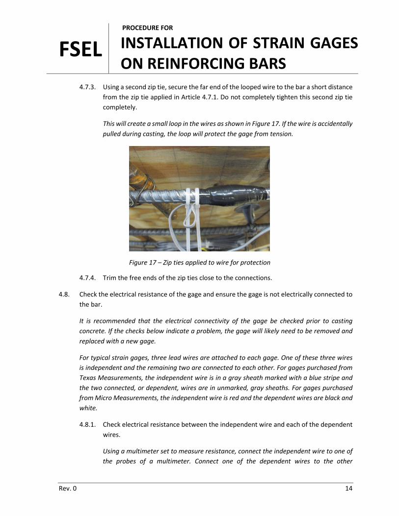
4.7.3. Using a second zip tie, secure the far end of the looped wire to the bar a short distance from the zip tie applied in Article 4.7.1. Do not completely tighten this second zip tie completely.
This will create a small loop in the wires as shown in Figure 17. If the wire is accidentally pulled during casting, the loop will protect the gage from tension.
Figure 17 – Zip ties applied to wire for protection
4.7.4. Trim the free ends of the zip ties close to the connections.
4.8. Check the electrical resistance of the gage and ensure the gage is not electrically connected to the bar.
It is recommended that the electrical connectivity of the gage be checked prior to casting concrete. If the checks below indicate a problem, the gage will likely need to be removed and replaced with a new gage.
For typical strain gages, three lead wires are attached to each gage. One of these three wires is independent and the remaining two are connected to each other. For gages purchased from Texas Measurements, the independent wire is in a gray sheath marked with a blue stripe and the two connected, or dependent, wires are in unmarked, gray sheaths. For gages purchased from Micro Measurements, the independent wire is red and the dependent wires are black and white.
4.8.1. Check electrical resistance between the independent wire and each of the dependent wires.
Using a multimeter set to measure resistance, connect the independent wire to one of the probes of a multimeter. Connect one of the dependent wires to the other

FSEL PROCEDURE FOR
INSTALLATION OF STRAIN GAGES ON REINFORCING BARS
Rev. 0 15
multimeter probe. These connections can be made by firmly pressing the bare wires to the multimeter probes. The measured resistance should approximately match the nominal resistance of the gage (120Ω or 350Ω). Perform this check on each of the two dependent wires.
4.8.2. Check the electrical resistance between each of the three lead wires and the reinforcing bar.
One at a time, connect each lead wire to a multimeter probe while holding the other multimeter probe firmly to the bare reinforcing bar. The multimeter should read “OL” for overload, indicating a very high resistance. The overload indicates the gage is electrically isolated from the bar as it should be.
4.9. Label all strain gage wires and bundle them together.
The lead wires must extend outside the concrete volume prior to casting. Typically, the wires are secured in bundles to nearby reinforcing bars using zip ties. The free end of the bundle should be placed to minimize interference with concrete casting and finishing operations.
4.10. Record the gage factor for the gage.
When setting up the data acquisition system, the gage factor will be needed to convert voltage measurements to strain values.
5. SUPPORTING DOCUMENTS
None.
6. REFERENCED DOCUMENTS
None.

FSEL PROCEDURE FOR
INSTALLATION OF STRAIN GAGES ON REINFORCING BARS
Rev. 0 16
7. RECORD OF REVISIONS
Revision Date Affected Pages Description
0 2016-09-23 All Initial Issue