Pro Mk2 04new - BattleBots & Combat Robotics Information · RB2 Reverse Forward 3 Features The...
16
www.4QD.co.uk [email protected] “We're in Control” “We're in Control” 36 Greenfields Earith Cambridgeshire PE28 3QH Instruction Manual Pro-120 series controllers Mark 2 series Foreword 4QD try to write a manual which is readable. Please read the manual through before starting installation. To help you, we have marked the more technical sections ¶ so that you may ignore them. This manual covers installation and wiring of 4QD's Pro series controller in the usual applications. There are finer points of installation which are outside the scope of such a printed manual and you should refer to our www site for more information. Models The Pro-120 is available either for 24v operation or for 12v operation. Models can also be supplied for 36v and 48v The voltage is marked on the relays. Make sure this are correct as 24v relays will not operate from 12v and 12v relays will soon burn out if used on 24v. The standard model is suitable for permanent magnet or shunt wound motors. Applications 4QD’s Pro range of 4 quadrant controllers are well suited to general purpose speed control applications where reversing is required. They are used extensively by hobbyists and industry. Amongst other applications our controllers have been successfully used in the following: Camera dollies Caravan shifters Carnival floats Conveyors Factory stores vehicles Floor cleaning machines Golf buggies Invalid scooters Kiddie cars Miniature railways, 3”, 5” and 7¼ gauge Mobile targets Mountain rescue vehicles Remote controlled vehicles (Robots) Ride on golf buggies Winches In fact wherever battery motor speed control is required Date printed: 27th January 2015
Transcript of Pro Mk2 04new - BattleBots & Combat Robotics Information · RB2 Reverse Forward 3 Features The...

www.4QD.co.uk [email protected]
“We're in Control”“We're in Control”
36 Greenfields
Earith
Cambridgeshire
PE28 3QH
Instruction Manual
Pro-120 series controllers
Mark 2 series
Foreword
4QD try to write a manual which is readable. Please
read the manual through before starting installation.
To help you, we have marked the more technical
sections ¶ so that you may ignore them.
This manual covers installation and wiring of 4QD's
Pro series controller in the usual applications. There
are finer points of installation which are outside the
scope of such a printed manual and you should refer
to our www site for more information.
Models
The Pro-120 is available either for 24v operation or
for 12v operation. Models can also be supplied for
36v and 48v
The voltage is marked on the relays. Make sure this
are correct as 24v relays will not operate from 12v
and 12v relays will soon burn out if used on 24v.
The standard model is suitable for permanent magnet
or shunt wound motors.
Applications
4QD’s Pro range of 4 quadrant controllers are
well suited to general purpose speed control
applications where reversing is required. They
are used extensively by hobbyists and industry.
Amongst other applications our controllers have
been successfully used in the following:
Camera dollies
Caravan shifters
Carnival floats
Conveyors
Factory stores vehicles
Floor cleaning machines
Golf buggies
Invalid scooters
Kiddie cars
Miniature railways, 3”, 5” and 7¼ gauge
Mobile targets
Mountain rescue vehicles
Remote controlled vehicles (Robots)
Ride on golf buggies
Winches
In fact wherever battery motor speed control is
required
Date printed: 27th January 2015

Page 2 Pro-120 controller instructions
Contents
Section
Introduction 1
Safety 2
Features 3
¶ Specifications 4
Mounting 5
Connections 7
Power Connections 8
Battery wiring 8.01
Motor wiring 8.02
Circuit breaker 8.03
Battery condition meter. 8.04
Controls 9
Speed pot 9.01
¶ Use as voltage follower 9.02
Ignition (On/Off) switch 9.03
¶ High Pot lock-out 9.04
¶ Battery Discharge Protection 9.05
Reversing switch 9.06
Section
Braking 10
Parking brake 10
Adjustments 11
Gain 11.01
Full speed 11.02
Ramps 11.03
RAT and MST 11.04
¶ Expansion connector 12
Heat & Heatsinking 13
Base and cover option. 14
Waterproofing 15
Choice of motor 16
Disabling Regenerative Braking 17
Common faults 18
Fuses 18
Service & Guarantee 19
More information 21
4QD’s Pro-120 is a reversing motor speed controller
for battery operated vehicles covering currents up to
120 amps (over 150 amps peak). They are available
for operation on voltages ranging from 12v to 48v.
They are high frequency chopper drivers giving
control of motor speed both in drive mode and in
braking mode. They use MOSFETs in state-of-the-
art high frequency circuitry to give best possible
performance and battery economy. The controllers
incorporate many advanced features such as reverse
polarity protection, regenerative braking,
independent, linear, adjustable acceleration and
deceleration ramps, controlled performance at power
down, reverse speed reduction, dual ramp reversing,
pot fault protection and electromagnetic brake driver.
Many of these features can be disabled if so required.
The simplest configuration is shown in section 7.
However because of the features and versatility of
our controllers we give a lot of extra information in
this manual - which may make it seem to be more
complicated than it is so we’ve marked the more
technical sections ¶ so you may ignore them. Please
don’t be put off but read the manual quickly through
before you start. This should introduce you to what
you can do with our controllers and clarify what we
are trying to say.
Our drives are protected: provided you don’t actually
connect them wrongly or short them out, they will
survive almost any type of motor for a short time- we
regularly use a 12v starter motor as a test load,
stalling it with a monkey wrench. The drives survive
this but will get hot and therefore will eventually fail.
1 Introduction
Handling - Important!
Before handling the controller, disconnect the
batteries and short out the controller’s battery input
terminals. This will discharge the main capacitors,
which otherwise can store charge for many minutes.
If any foreign body contacts the board while these
capacitors are still charged, the controller may be
damaged.
MOSFETs tend to fail safe (i.e. open-circuit) so
failure to full speed is very unlikely. However, if the
controller is not mounted properly water might get
onto the board: no designer can make a controller
operate properly under these conditions.
The Pro has a power disconnect relay and special
sensing circuitry. If the ignition switch is switched
off at full speed then internal circuitry ramps the
2 Safety

Page 3Pro-120 controller instructions
controller down, slowing the machine.When the
controller’s output stops switching (i.e. at zero
speed), the power relay switches off.
Reversing on the Pro series controllers is normally
‘dual ramp’ but can be changed to 'pre-select' by
removing a jumper on the board.
Dual Ramp Reversing means that, when the
reversing switch is operated at speed, the controller
slows down under control of the deceleration ramp,
automatically reverses when motor speed gets near
zero and accelerates again under control of the
acceleration ramp. If the ramp controls are set for
quick response this process can be quite violent.
Also, reversing is done by monitoring the demand
speed (after the ramping circuit) and not by
measuring the motor voltage. Therefore, if the
vehicle is reversed when going down a hill, motor
will still be rotating and the vehicle will be travelling
when reversing occurs. Reversing can therefore be
accomplished on any hill but it will be more or less
violent depending on the setting of the ramp
controls. The user is however best advised therefore
not to reverse at speed. We make no guarantees
about the mechanical effects!
Pre-select Reversing
Dual ramp reversing can be disabled on-board, when
the reversing becomes pre-select. The selected
direction will only be engaged when the throttle pot
is advanced from zero. If pre-select is used with a
joystick the controller will not reverse unless the
stick is held at zero until the motor has stopped.
Regen Braking
Regenerative braking is very reliable. However, it
works by feeding power back into the battery. If
your battery is already fully charged then regen
braking may have difficulty in operating as it has to
overcharge the battery. A similar problem exists if
the battery is disconnected, or the wiring faulty.
There are several options as to how the controller
should react under such fault conditions so if in
doubt, ask!
In any case, all passenger carrying vehicles should
be fitted with mechanical brakes: it is unwise to rely
on the battery as an emergency brake!
Charger Inhibit
Some machines have in-situ battery charging. Other
machines are designed so that the batteries have to
be removed for charging. Where the batteries are left
connected during charging, it may be considered
desirable to stop the user driving off before
disconnecting. This is the function of ‘Charger
inhibit’.
The Pro-120 has no separate inhibit input, so it is
necessary to be a little clever with the existing
inputs. You can use a switched socket for the
charger. This is a socket with an auxiliary switch
which is broken when the (charger) plug is inserted.
Such a break switch should be wired in-series with
the ignition switch, so the ignition cannot be
activated when the charger is connected.
Failing this, you can use a third pin on the charger
connector, wired as shown below.
When the charger is inserted, the link is made,
shorting the wiper of the throttle pot to battery
negative. Even if the ignition is now switched on, no
speed can be selected so the machine cannot drive.
The female part should be on the vehicle with its
sockets arranged so no metal object can touch them
when the charger is unplugged.
Many 3 pin connectors have one pin advanced so
that it is the first contact to make when the plug is
inserted. This pin should be battery negative since, if
any other pin made contact, battery positive could be
applied back to the pot wiper with destructive
consequences!
SocketB+
B-
centre of pot (pin E)Charger +
Charger -
Plug

Page 4 Pro-120 controller instructions
S
30-3B-2-04
1
21
2
22
3
23
4
24
25
16 17
18
19
30 31
32
8
9
12
CB5 0AH U K4 Q D
www.4qd.co.uk
1 2 3 4 5 6 7 8 9
10
5
2927
28
26
15
13
10
0K
10
K3K
3
3M
3
10
0K
10
0K
9V1
1µ0
10
0n
4µ7
1µ0
4µ7
N
1µ0
10
n
P
10
n
NP
N
P
N
NN
N N P
N
N
PP N
NNN
P P
1µ0
N
1K
5
1K
0
3V
9
10
K
33
K
4K
7
33
0K
33
K
330K
3K3
180K
10
K 9V
1
10
K
47
K
10
K10
K
10
0K
22
K
10
0K
10
0K
10
0K
10
0K
10
K
10
K
10
K
1N
40
0?
1N400?
4K
7
4K7
4K7
10
0K
10
K
10
K
10
K
33
0K
10
0K
10
0K
33
K
6R
8
3K
3
33
K
47
K
4µ7NN
P
10
R10
R
10R
10
R10
R
HPLO
DRR
RB1
10
K
33
0K
33
0K
10
n
10n
10
K
1µ0
47
K
10R
C1
C2
C3
C4
C5
C6
C7
C8
C9B
C9A
C10
C11
C11b
C12
C13
C14
C15
C16
C17
20
47µ1µ0
C19
C21C22C20
C23
C2410p
10
p
22
K10
0K
10
0K
18
0K
RB2
12
0K
47v
14
1K0 N10
0n
10
K18
0K
10
0n
1M
0
10
0p
330p
100R
100K10K
47
K
18
R10
K
Z‡
33
K ‡
10
K
10
K
10
K
10
K
1K
5
10
0K
10
0K
10
0K
10
0K
10
0K
100K
100K
100K
100K
1K
0
1µ0
1K
0
N
6V
2
4K
7
10
K10
KPBDP
10
0K
22
K
10
K
10
K
N76
47
0RP 1
8R
10
K8V
2
10K
33
0p
330p
1K
0
Full speedHalf speed
Dual Ramp Reverse
Gain
Accel
MST
RAT
Decel
Expansion connector HPLO Thermal sensor Trickle resistorUVP
Brake drive transistor
Battery +
Controls
Parking brake
Motor −
Motor +
Battery −
ABCD
FE
ABC
RB1
RB2
Reverse
Forward
3 Features
The Pro-120 has double 9.5mm motor tabs, for one
or two motors and single 9.5mm battery tabs. Also
fitted on the battery terminals is a set of 6.3mm
blades, to connect a charger or for similar purpose.
These are illustrated below.
Also available is an expansion connector option as
shown above, see section 12.
There are several on board options which can be
altered by removable jumpers:
Feature Section Page
High Pot Lockout 9.04 8
UVP (Battery Discharge Protection) 9.05 8
Reverse speed 9.07 9
Dual ramp/Preselect reversing 9.08 9
Regenerative Braking 17 15
There are also several user adjustments:
Gain 11.01 10
Acceleration 11.03 10
Deceleration 11.03 10
RAT 11.04 11
MST 11.04 11
For shipping, the mating parts of the 'Controls' and 'Parking brake' connectors are inserted into the sockets
on the board. See page 7.
Single 9.5mm
Double 9.5mm
Cover (optional)
Heatsink (optional) Relays
Battery & Motor connections
Pot & direction switch via IDC
Splashplate (with cover)
Page 5Pro-120 controller instructions
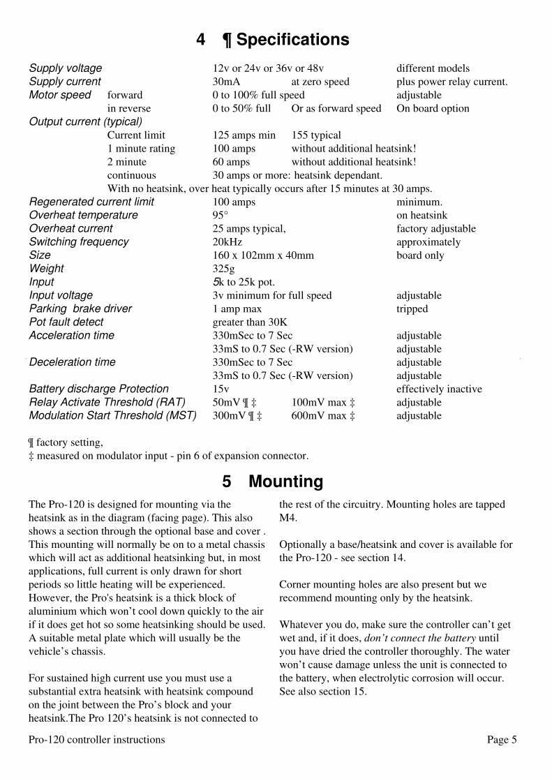
4 ¶ Specifications
5 Mounting
The Pro-120 is designed for mounting via the
heatsink as in the diagram (facing page). This also
shows a section through the optional base and cover .
This mounting will normally be on to a metal chassis
which will act as additional heatsinking but, in most
applications, full current is only drawn for short
periods so little heating will be experienced.
However, the Pro's heatsink is a thick block of
aluminium which won’t cool down quickly to the air
if it does get hot so some heatsinking should be used.
A suitable metal plate which will usually be the
vehicle’s chassis.
For sustained high current use you must use a
substantial extra heatsink with heatsink compound
on the joint between the Pro’s block and your
heatsink.The Pro 120’s heatsink is not connected to
the rest of the circuitry. Mounting holes are tapped
M4.
Optionally a base/heatsink and cover is available for
the Pro-120 - see section 14.
Corner mounting holes are also present but we
recommend mounting only by the heatsink.
Whatever you do, make sure the controller can’t get
wet and, if it does, don’t connect the battery until
you have dried the controller thoroughly. The water
won’t cause damage unless the unit is connected to
the battery, when electrolytic corrosion will occur.
See also section 15.
Supply voltage 12v or 24v or 36v or 48v different models
Supply current 30mA at zero speed plus power relay current.
Motor speed forward 0 to 100% full speed adjustable
in reverse 0 to 50% full Or as forward speed On board option
Output current (typical)
Current limit 125 amps min 155 typical
1 minute rating 100 amps without additional heatsink!
2 minute 60 amps without additional heatsink!
continuous 30 amps or more: heatsink dependant.
With no heatsink, over heat typically occurs after 15 minutes at 30 amps.
Regenerated current limit 100 amps minimum.
Overheat temperature 95° on heatsink
Overheat current 25 amps typical, factory adjustable
Switching frequency 20kHz approximately
Size 160 x 102mm x 40mm board only
Weight 325g
Input 5k to 25k pot.
Input voltage 3v minimum for full speed adjustable
Parking brake driver 1 amp max tripped
Pot fault detect greater than 30K
Acceleration time 330mSec to 7 Sec adjustable
33mS to 0.7 Sec (-RW version) adjustable
Deceleration time 330mSec to 7 Sec adjustable
33mS to 0.7 Sec (-RW version) adjustable
Battery discharge Protection 15v effectively inactive
Relay Activate Threshold (RAT) 50mV ¶ ‡ 100mV max ‡ adjustable
Modulation Start Threshold (MST) 300mV ¶ ‡ 600mV max ‡ adjustable
¶ factory setting,
‡ measured on modulator input - pin 6 of expansion connector.

Page 6 Pro-120 controller instructions
6 core cable
Speed control potBattery Condition Meter
Ignition wire removed
To fit battery dischargeprotection.
Reverse switch
Ignition switch
Black
Green
Blue
Red
Black
Black
Blue
Red
RedRed
Yellow
White
R fitted (12K)uvp
Permanentmagnetmotor
YellowWhiteBlack
GreenBlueRed
Fuse or breaker, see text
The diagram shows the simplest connections needed
to use the controller.
More information on wiring follows.
Yellow is directly connected to battery +ve. White
and black may also be battery +ve (depending on the
control switches). Green is battery -ve and blue and
red are the control pot.
Fuse in yellow wire is optional but recommended -
see p 15.
7 Connections
8.01 Battery wiringUse only good quality battery connectors: the
controller feeds current back the battery during
braking and if a battery connector falls off when
braking this regenerated current can pump up the
voltage on the dud battery connection. Although the
controller is protected against damage, this is not
advised since control is lost. The same will happen if
a fuse or circuit breaker opens during braking.
Wire size.
Use heavy duty wire for the battery leads and make
them as short as possible. This also applies to the
battery linking wire on 24v systems.
4mm (12awg) wire is ‘officially’ rated to handle 41
amps continuously. At 100 amps it gets too hot to
touch within about 60 seconds. We therefore suggest
you use at least 6.0mm² (10awg) wire for battery
connections.
On the 12v controllers, voltage loss in the wire is
important and you may need to use two lengths of
6mm² wire for the battery - depending on their
length. Excessive voltage loss will cause the voltage
8 Power Connections

Page 7Pro-120 controller instructions
at the controller to fall so low that the controller
detects a fault condition and the relay will switch off.
On the 24v versions, use of wire that is too long
(and/or too thin) will cause loss of power but will not
harm the controller although the decoupling
capacitor (see ‘features’ diagram above) may heat
up. Heat will shorten the operating life of capacitors.
Crimp Contacts
You must use fully insulated crimps: the power
connections are close to each other and uninsulated
crimps may short out and cause damage. Best of all
use ‘F type’ crimps with vinyl covers. 4QD can
supply these pre-crimped only as they require a
special crimp tool.
8.02 Motor wiring
This is not quite so critical as battery wiring: too
long and/or too thin wire will cause a loss of
performance, it will get and will waste battery power
but will not damage the controller. However, wire
which is too thick will do no harm either so we
recommend the same wire for the motor as for the
battery.
8.03 Circuit breaker
A fuse or circuit breaker may be fitted if required.
The main advantage is that it will enable the battery
or motor to be disconnected in the event of an
emergency or for security. A circuit breaker will not
protect the drive in the event of a fault: MOSFETs
fail far faster than a circuit breaker can operate.
This may be fitted in the battery lead as shown: take
care not to increase the wiring length too much.
Also, certain types of breaker can have the same
effect as increased battery lead length. A breaker in
the motor may therefore be best: it will enable you to
quickly disconnect the motor in an emergency. Also
with the motor disconnected, freewheeling becomes
possible. It is also possible to get a battery isolator
switch - these are normally fitted to lorries, buses
and boats to isolate the battery in an emergency - but
this is not required as the Pro-120 has a power relay
which effectively disconnects the battery (except for
a small bleed resistor).
8.04 Battery condition meter.
This should connect between Pins B and F (white
and green on the diagram). White is connected via
the ignition switch to battery positive and green is
always connected via the wiring to the battery
negative.
9 Controls
The mating connector supplied is
suitable only for the correct size of wire.
Acceptable wire sizes are:
7 stranded 0.22-0.25mm²
24 AWG (7/32 AWG)
It is an Insulation Displacement
Connector (IDC):
Do not strip the insulation from the
wires, simply push them into the top part
of the open connector, from the front
(visible in the diagram) and squeeze it
closed in a vice or with suitable parallel
action pliers. As you do so, the tines of the contacts
bite through the insulation to make contact with the
conductors.
You can re-open a closed connector by gently
moving the tabs at the sides of the top cover outward
to disengage the latches while lifting the cover
slightly, one side at a time.
Wire which is too thin will not make good contact.
Wire which is too thick will damage the tines which
may short to each other
Solid wire will quickly break with use.
Under no circumstances should you solder to the
connector or the circuit board.
ABCDEFClosedOpen
D red: Max speed (about 7v when ign on)E blue: Wiper (0 to Max Speed, as pot is varied)F green: 0v (Min speed)
C black: Reverse (0v = forward, >5v = reverse)
A yellow: +24v (V Batt) to IgnitionB white: Ignition
A B C D E F
1
1

Page 8 Pro-120 controller instructions
9.01 Speed pot
We advise a 10K linear pot, although you can use
any value from 4K7 to 20K.
The gain adjustment on the
controller alters the amount of
rotation required before full speed
is reached: this allows various
input devices to be used.
The simplest speed control is an
ordinary rotary pot: this won’t give
any ‘dead man’ control as the pot
won’t return to zero when it is
released. 4QD can supply a spring
return to zero hand control or a
plunger operated pot (linear
position sensor), suitable for
incorporating into a foot pedal.
9.02 ¶ Use as voltage follower
Instead of a pot, the input may be fed from a variable
voltage. 0v (common) to pin F, signal input (+ve) to
pin E. A resistor (10k) should be connected from pin
D to pin F to over-ride the internal pot fault detector
circuit. Zero speed will be for zero voltage input and
full speed voltage may be adjusted (by the pre-set) to
be from 3v to above 20v.
The reverse line may also be operated by a voltage.
With zero volts present controller will operate in
forward. Apply a voltage (any voltage over
approximately 5) and reverse will be selected.
9.03 Ignition (On/Off) switch
Circuitry in the controller switches it off (zero
current consumption) unless pins A and B of the
connector are joined. Therefore a switch must be
fitted.
There are three ways of factory wiring the
ignition:the following notes apply to the standard
controller, not to the RW version.
Do not permanently link these pins. For correct
operation, the ignition switch must be turned on (or
the hand control box plugged in) after power has
been applied to the controller. If the ignition switch
is turned on before power is applied then the ignition
relay may not pull in properly as its operation relies
on the Pro’s internal capacitor charging through a
bleed resistor before the ignition switch is closed.
Beware of opening the switch when the motor is
running: the motor will brake to a halt more or less
quickly, depending on the deceleration ramp setting.
With the ignition off, or even
with the battery disconnected,
the relays short out the motor
so free-wheeling is not
possible. To freewheel
properly the motor should be
disconnected.
The Pro controller has special
circuitry so that, if the ignition
is switched off at full speed,
the motor will be braked to a
stop (under control of the
deceleration ramp) and only
when it has stopped will the
ignition relay switch off. For
this to work properly it is important that the ‘Gain’
control is not turned up too far - see section 11.01.
9.04 ¶ High Pot lock-out
This feature switches off the ignition if this is
activated with the speed pot other than at low speed
to guard against the vehicle taking off because the
ignition is activated with the throttle depressed.
In some applications this feature may be undesirable.
e.g. with a Joystick Interface when the system will
not power up unless the stick is central at switch on -
this can cause confusion!. It can be disengaged by
simply removing the header marked HPLO on the
diagram ‘features’ - page 4.
Note: the Trickle Resistor (p.4) may get hot when
HPLO is engaged and a relay may click on and off.
9.05 ¶ UVP (Battery Discharge Protection)
this can be used to protect the the battery from
damage that could be done by over-discharging it.
To do this, the voltage at the controllers battery
terminals is monitored and the performance is
reduced as this voltage falls.
The level is factory set to a low voltage (about 15v)
so the feature is effectively inactive on 24v
controllers. For 12v controllers the feature must be
totally deactivated by fitting the header marked UVP
in the features diagram (page 4).
To enable UVP on 24v, fit the 12K resistor Ruvp
Speed
Min Max
On
Off
Reverse
Forward
F
ED
C
BA
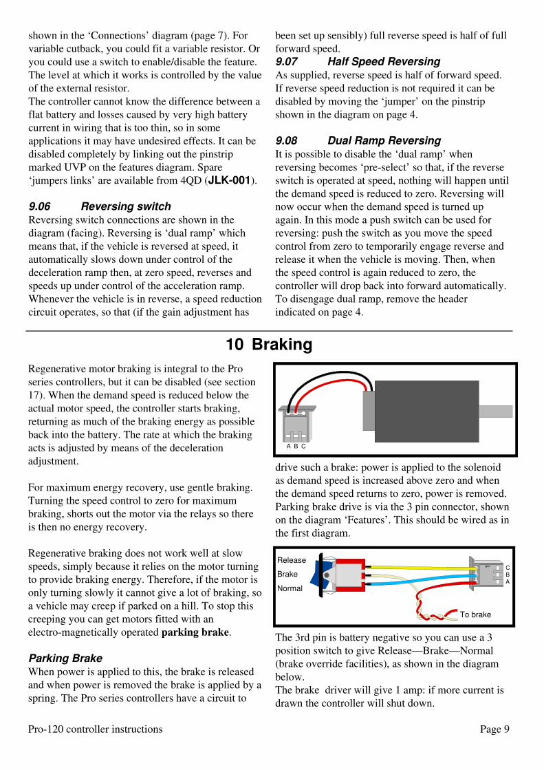
10 Braking
Page 9Pro-120 controller instructions
Regenerative motor braking is integral to the Pro
series controllers, but it can be disabled (see section
17). When the demand speed is reduced below the
actual motor speed, the controller starts braking,
returning as much of the braking energy as possible
back into the battery. The rate at which the braking
acts is adjusted by means of the deceleration
adjustment.
For maximum energy recovery, use gentle braking.
Turning the speed control to zero for maximum
braking, shorts out the motor via the relays so there
is then no energy recovery.
Regenerative braking does not work well at slow
speeds, simply because it relies on the motor turning
to provide braking energy. Therefore, if the motor is
only turning slowly it cannot give a lot of braking, so
a vehicle may creep if parked on a hill. To stop this
creeping you can get motors fitted with an
electro-magnetically operated parking brake.
Parking Brake
When power is applied to this, the brake is released
and when power is removed the brake is applied by a
spring. The Pro series controllers have a circuit to
drive such a brake: power is applied to the solenoid
as demand speed is increased above zero and when
the demand speed returns to zero, power is removed.
Parking brake drive is via the 3 pin connector, shown
on the diagram ‘Features’. This should be wired as in
the first diagram.
The 3rd pin is battery negative so you can use a 3
position switch to give Release—Brake—Normal
(brake override facilities), as shown in the diagram
below.
The brake driver will give 1 amp: if more current is
drawn the controller will shut down.
A B C
Release
Brake
Normal
To brake
1
ABC
shown in the ‘Connections’ diagram (page 7). For
variable cutback, you could fit a variable resistor. Or
you could use a switch to enable/disable the feature.
The level at which it works is controlled by the value
of the external resistor.
The controller cannot know the difference between a
flat battery and losses caused by very high battery
current in wiring that is too thin, so in some
applications it may have undesired effects. It can be
disabled completely by linking out the pinstrip
marked UVP on the features diagram. Spare
‘jumpers links’ are available from 4QD (JLK-001).
9.06 Reversing switch
Reversing switch connections are shown in the
diagram (facing). Reversing is ‘dual ramp’ which
means that, if the vehicle is reversed at speed, it
automatically slows down under control of the
deceleration ramp then, at zero speed, reverses and
speeds up under control of the acceleration ramp.
Whenever the vehicle is in reverse, a speed reduction
circuit operates, so that (if the gain adjustment has
been set up sensibly) full reverse speed is half of full
forward speed.
9.07 Half Speed Reversing
As supplied, reverse speed is half of forward speed.
If reverse speed reduction is not required it can be
disabled by moving the ‘jumper’ on the pinstrip
shown in the diagram on page 4.
9.08 Dual Ramp Reversing
It is possible to disable the ‘dual ramp’ when
reversing becomes ‘pre-select’ so that, if the reverse
switch is operated at speed, nothing will happen until
the demand speed is reduced to zero. Reversing will
now occur when the demand speed is turned up
again. In this mode a push switch can be used for
reversing: push the switch as you move the speed
control from zero to temporarily engage reverse and
release it when the vehicle is moving. Then, when
the speed control is again reduced to zero, the
controller will drop back into forward automatically.
To disengage dual ramp, remove the header
indicated on page 4.

Page 10 Pro-120 controller instructions
11 Adjustments
Do not use excessive force when adjusting the
presets: these are quite small and are easily damaged.
11.01 Gain
This is marked ‘Gain’ on the diagram ‘Features’. Set
this so that, at maximum required pot range, the
controller just reaches full speed: this is easiest to do
with the motor unloaded. Set the speed pot to your
required maximum point (e.g. full up) then, listening
to the motor, adjust the preset. It it usually quite easy
to tell when the motor stops accelerating. Too low a
setting and the motor will not reach full speed (this
can be useful to restrict top speed).
Too high a setting and there will be a ‘flat’ spot at
maximum speed where the control has no effect.
This will also confuse the special ‘power down’
circuitry so you will get a bumpy ride if you switch
off at speed.
Maximum setting of the gain preset will give full
output for about 3v input. The sensitivity can be
increased by fitting a resistor: contact the factory for
details.
11.02 Full speed
Where user adjustment of the top speed is required
the ’gain control’ is not satisfactory. In this case the
arrangement below can be used.
Both pots should be the same value (10K). The
resistor shown in the green lead to the top speed
adjust pot is optional: if left out (open-circuit) the top
speed will adjust between 50% and 100%
resistor
none 50% - 100%
10K 33% - 100%
4K7 25% - 100%
3K3 20% - 100%
2K2 15% - 100%
1K2 10% - 100%
linked: 0% - 100%
Alternatively, you can simply fit a resistor in the top
of the pot (red wire) but the value of this resistor plus
the pot should not exceed 20K.
11.03 Ramps
The Pro series controllers incorporate very
sophisticated ramps to control the acceleration and
deceleration rates. These are user adjustable and, to
get best performance from your machine, you should
adjust them!
Acceleration ramp
This is shown as ‘Accel’ on the ‘Features’ diagram.
It is present to make the vehicle accelerate smoothly
when the speed pot is increased suddenly so as to
avoid sudden surges and shocks to the mechanics. As
supplied it is at half setting so that the motor takes
about 3 seconds to accelerate.Adjust it as you require
to give smooth acceleration. Clockwise increases the
time (reduces the acceleration) anticlockwise
decreases the time (increases the acceleration) If the
time is set too short (anticlockwise) the vehicle’s
acceleration will be limited by the current limit
which does no harm (except that repeated accel/decel
will cause over heating) but it means that
acceleration is not being controlled properly, so will
vary depending on the gradient.
Deceleration ramp
This is shown as ‘Decel’ on the Features diagram: it
is present to make the vehicle decelerate smoothly
when the speed pot is reduced suddenly. As supplied
it is at half setting (about 3 seconds). Adjust it as you
require to give smooth deceleration. You will usually
find you require a lower setting (more anticlockwise)
for Decel than for Accel. If the Decel time is set too
low (anticlockwise) then the relays will drop out and
short out the motor before regenerative braking has
finished. This may give a jerk before the vehicle
stops completely and may also shorten the life of the
relays.
11.04 RAT and MST
Two other presets exist: we advise against altering
these.
Normal setting is centre scale.
Another sensible setting is with both fully
clockwise.
RAT. As the throttle is moved from zero, at a low
setting one or other direction relay engages
(depending on the selected direction). This is the
RAT (Relay Acceptance Threshold). At the same
Blue
Green
Top speed adjust
Speed control pot
Red

Page 11Pro-120 controller instructions
12 ¶ Expansion connector
This 9 way connector may be fitted as an option.
Additional features (such as tachogenerator closed
loop control and IR compensation) can be added
here. It is also for ganging two Pro-120 controllers
together, to drive two motors simultaneously, when
the combination can control up to 240 amps of motor
current, making the combination quite suitable for
even high performance ride-on golf buggies. For
quantity orders 4QD can supply a slave version -
contact the factory for more information.
Double headingWhen two standard controllers are used, one is the
master the second is the slave. This combination
might be used, for example, in an electric railway for
‘double heading’ a train with one engine at each end.
The controller which is to be the slave should have
its ignition switched off, it will be controlled by the
master.
The slave controller need have only battery
connections and connections to the second motor. It
is connected to the master Pro by a 4 way cable
between the two expansion connectors.
This cable should join as follows:
Pin numbers are printed on the circuit board.
The two controllers will work as one, controlling the
two motors together with the gain and ramp
adjustments of the master controlling both.
HPLO should however be disabled - either on both,
or just on the slave, or it will engage causing one
controller not to work (power relay will click on and
off).
Slaving is automatic: with the wire linked as shown
one will be slave (whichever you chose to drive
from!) and with the link disconnected, they will be
independent.
The two motors will perform identically but with
independent current limits. If two motors are used
off one single 200 amp controller, then the full 200
amps current is available to drive either motor in
stall conditions. With the Pro-120, each motor may
only draw up to 120 amps, limited by its own
controller. The system therefore offers more
protection to the motors. Also, if one motor gets
disconnected, the second motor will still be
protected. Lastly, if there is a failure in one
controller the chances are that the vehicle may still
be operable on the other controller, providing an
emergency ‘get you home’ service, albeit at reduced
performance.
Other Uses
The expansion connector is designed to allow
additional facilities to be fitted - so there are many
possibilities!
point, the parking brake is released.
MST. As the throttle is further advanced then,
normally just above the RAT, the controller starts to
modulate: i.e. it starts switching and voltage is fed to
the motor. This is the MST (Modulation Start
Threshold).
Because of stiction in the motors, they need a small
voltage before they start to rotate: this will occur at a
slightly higher throttle setting.
Full speed is reached approximately 3v above the
MST (measured on pin 6 of expansion connector).
In certain applications, altering these adjustments
can make for better low speed control, near zero
speed. For instance, increasing RAT could suppress
relay jitter in a radio control application.
Master Slave Function
pin 1 pin 1 Ignition
pin 2 do not connect +9v
pin 3 do not connect Oscillator
pin 4 do not connect Oscillator
pin 5 pin 5 Speed
pin 6 do not connect Speed
pin 7 pin 7 Direction
pin 8 do not connect Current limit
pin 9 pin 9 0v
31
2 3
4 5
6 7
8 9
N

Page 12 Pro-120 controller instructions
14 Base and cover option.(facing page)
The diagram shows the dimensions of 4QD’s base
which is available as an option.
Two A holes are for mounting the Pro-120’s
heatsink onto the base plate.
Four B holes are for mounting the cover.
Two C holes are mounting holes in the baseplate.
The board is shown cut away (the oval hole) to show
the position of the Pro 120’s heatsink block.
Base and cover are available separately so you may
use your own base.
The cover is supplied with four plastic ‘push rivets’
which locate in the ‘B’ holes.
Alternatively the cover may be fixed by using double
sided adhesive tape around the rim of the cover.
Mounting the cased controller.
Mounting holes are pre-drilled in the base plate but
if alternative mounting points are required and there
are virtually no restrictions on positioning.
The supplied holes are M5 tapped.
You can of course clamp mount the controller by
metal plates clamping onto the periphery of the
controller.
Do not drill extra holes in the base: swarf could get
into the controller and this will invalidate any
warranty.
13 Heat & Heatsinking
The long time current the controller can give is
limited by the build up of heat in the heatsink. The
controller will give over 110 amps for one minute -
this is limited by the heatsink and by heating in the
printed wiring, relays and other components. For
periods of more than a minute you need an external
heatsink to remove heat.The available continuous
current will depend on this external heatsink.
Steel is not a good heatsink material: heat does not
flow easily in steel. Aluminium or copper is far
better. If you have a steel plate, sandwich an
aluminium sheet between the steel and the Pro to
spread the heat.
For really arduous use we suggest heatsink
compound between the Pro’s heatsink and your own:
this helps heat flow across the join. Make sure both
surfaces are flat and free of grit.
Pro-120 incorporate a thermal sensor which cuts
back the output current if the controller gets too hot
(95°C) so the available current is (only) about 25
amps. At this current the MOSFETs will dissipate
about 20 watts. This is still enough to keep the
heatsink hot so don’t rely too heavily on it!

Page 13Pro-120 controller instructions
113.9
181
166
121118
0
0 3
15
47.8 73.2
A A
B
B
B
B
50
60.5
C
126C

Page 14 Pro-120 controller instructions
15 Waterproofing
The cover is a vacuum forming which is waterproof.
The cased assembly is best mounted with the
heatsink at the bottom: water may run over the
aluminium base with no problem - in fact water on
the base would have to be about 10mm deep before it
touched anything electrically live.
In the mouth of the cover you should fit a splash
plate (supplied with the cover) in the position shown
in diagram 6. The splash plate should be
sealed/glued in place with suitable silicone rubber
(Dow Corning 734 RTV) between plate and circuit
board. Run a fillet of rubber along the top edge of the
plate and push it up to the relays. Leave the assembly
board-side down while the rubber sets so that it runs
down to the circuit board forming a seal. When
supplied as a controller with case, 4QD will fix the
splash plate in position.
The cover has a strip of foam already fitted to help
sealing between cover and board. However you must
not let water get onto the board - at the very least
electrolytic corrosion will occur - so take a moment
to consider what will happen if water runs down the
leads to the controller: put a kink in the leads so
water drops off at that point.
If mounting the controller on its side, remember that
if water gets into the mouth it could sit inside the
controller and could easily touch the circuit board.
Either make sure water cannot enter or else drill a
drainage hole in the bottom side of the cover, at the
mouth, so water can escape. We also suggest you
seal the splash plate to the side of the cover with
silicone rubber.
16 Choice of motor
All speed controllers should only be used with good
quality motors. Motors with damaged, worn
brushgear will causes arcing. On occasion brush
arcing can cause seemingly random controller
failure. This effect is quite rare, but be careful.
Ideally the motor should include an internal
suppression capacitor, a ceramic type of 10n value is
ideal. If the motor does not include this you are
advised to fit one across the brushes as close as
possible to the motor body. The controller will work
without this capacitor, but fitting it can lengthen the
life of the system.
A word of warning: many car type motors have the
chassis connected to one terminal. Take great care
with these as you could easily short the controller out
- which would be fatal. It is best to avoid these
motors. Otherwise either make sure the motor is
mounted on insulation (including the drive shaft), or
make certain that no other point of the control
system can be earthed to chassis.
Most modern d.c. motors use permanent magnets.
These are the best for battery operation. However,
other types can be used: at 4QD we regularly use a
12v car starter motor for testing (even with our 24v
150 amp drives) since these are a far worse load than
is ever likely to be met. Into such a motor (stalled)
the controllers simply deliver their maximum current
and quickly get hot. It is virtually impossible to
damage the controllers by an unsuitable motor (the
controller will simply get hot quickly), so don’t be
afraid to experiment.
There is no reason why you cannot use a 24v motor
from 12 volts - it will only go at half its design
speed. Also, if you use a 12 volt motor from 24v, it
will go at twice its rated speed. Since the Pro is
current limited you won’t overload the 12v motor,
provided it can handle the available (limited) current.
Shunt wound motors are suitable - they react as a
permanent magnet one.
Series wound motors are not suitable for the standard
controller because they will not reverse by normal
armature control.
The nameplate current quoted for motors is normally
a continuous rating: most motors will safely take an
overload of about 400% for short periods.
The current the motor actually requires is determined
by the mechanical loading, not by the controller or
the motor. If the motor is too small, it will overheat
and if the controller is too small, then it will
overheat. For more information on motors see our
www site
Page 15Pro-120 controller instructions
18 Common faults
There are no ‘common’ faults: as soon as 4QD find a
fault which occurs which can be prevented, we try to
alter the design to eliminate it. This makes it difficult
to give you sensible fault finding tips - but it does
improve our product!
Most controllers returned for attention are either nor
faulty or have been damaged by ‘foreign bodies’:
nuts and bolts in the works or water etc.
There's a lot more service and fault finding info on
our www site: www.4QD.co.uk/serv/ than we can
print here!
Controller appears to be dead
Check the High Pot lockout (page 8) and the pot you
are using. HPLO and pot fault detector are intended
to detect faults and stop the controller from
working.
If HPLO engages, it will cause the power relay to
deactivate.
If a Pot fault is detected, it will simply prevent the
controller giving any output, but will not disengage
the relay.
Controller switches off erratically
The protection circuitry will switch the controller off
in the event of a fault: faults inside the controller are
rare and generally are not erratic: the controller
works or it fails.
Parking brake is used: if this is faulty or is drawing
too much current, the controller will switch off and
this will seem erratic.
Otherwise: if too low a pot value is used or some
other device draws current from the pot supply, a
fault will be detected.
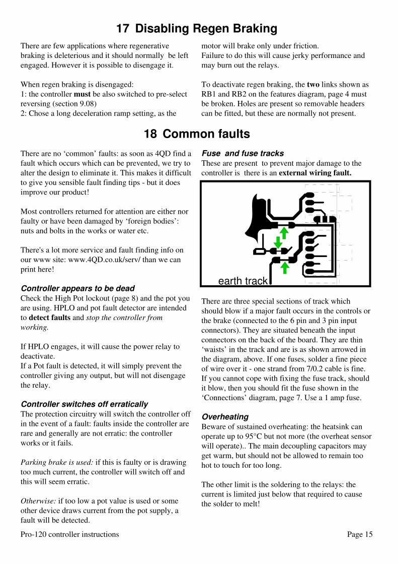
Fuse and fuse tracks
These are present to prevent major damage to the
controller is there is an external wiring fault.
There are three special sections of track which
should blow if a major fault occurs in the controls or
the brake (connected to the 6 pin and 3 pin input
connectors). They are situated beneath the input
connectors on the back of the board. They are thin
‘waists’ in the track and are is as shown arrowed in
the diagram, above. If one fuses, solder a fine piece
of wire over it - one strand from 7/0.2 cable is fine.
If you cannot cope with fixing the fuse track, should
it blow, then you should fit the fuse shown in the
‘Connections’ diagram, page 7. Use a 1 amp fuse.
Overheating
Beware of sustained overheating: the heatsink can
operate up to 95°C but not more (the overheat sensor
will operate).. The main decoupling capacitors may
get warm, but should not be allowed to remain too
hot to touch for too long.
The other limit is the soldering to the relays: the
current is limited just below that required to cause
the solder to melt!
earth track
There are few applications where regenerative
braking is deleterious and it should normally be left
engaged. However it is possible to disengage it.
When regen braking is disengaged:
1: the controller must be also switched to pre-select
reversing (section 9.08)
2: Chose a long deceleration ramp setting, as the
motor will brake only under friction.
Failure to do this will cause jerky performance and
may burn out the relays.
To deactivate regen braking, the two links shown as
RB1 and RB2 on the features diagram, page 4 must
be broken. Holes are present so removable headers
can be fitted, but these are normally not present.
17 Disabling Regen Braking

19 Service & Guarantee
20 Other products
All 4QD’s products carry the normal 12 month
guarantee against faults of original manufacture.
Outside the guarantee period, or when the fault is not
due to faulty manufacture, we can normally repair
the controller, subject to it not being of excessive age
(about 5 years)
This offer does not apply if the controller has been
modified in any way or if the controller is returned
attached to any customer’s metalwork or wiring:
such alterations/additions mean the controller won’t
fit 4QD’s test jigs and an extra charge will be made
for handling and postage, even when the controller is
covered by the guarantee.
It also saves postage (both ways) if the controller is
returned without the base plate attached.
21 More information
IDC wire size
Some problems are caused by the use of the wrong
wire size or type in the IDC connectors. Wire that is
too thin may make poor contact. If it is too
thick(16/0.2) it may cause shorts. Single stand wire
can break.
MOSFETs
MOSFETs do fail occasionally, but in practise
failures are very rare. They are doing an enormous
amount of work and sometimes one simply gives up:
commonly the drive MOSFETs cause their drive
resistors to burn up - a sure sign the MOSFET has
failed.
Relay drop-out
A flat battery or wiring which is too thin can cause
excessive voltage drop. If the supply voltage gets to
low then, on the 24v controllers, the battery
discharge protection operates and reduces controller
performance.
On the 12v controllers, discharge protection is not
fitted as standard - so the internal 9v rail can drop. If
it does, the relay will drop out, switching off the
controller. The controller will work happily down to
10.5v (the minimum you should discharge a battery).
Sticky relays.
The power relays are switched by the controller at
low current so are very reliable. However a wiring
error can cause an arc at the contacts which are
delicately balanced against the spring to maximise
contact pressure. So a small arc can, on occasion,
cause a relay to stick. If a relay does not click when
expected, it is worth tapping it with a screwdriver
handle, to see if it is sticking.
4QD manufacture a full range of controllers: from
our Eagle and 1QD series through to our high current
4QD series (up to 300 amps, 48v) as well as a range
of extras such as LED voltmeters for 12v and 24v,
joystick interfaces and a timer for ‘stand-off’
operation in golf caddies. We also manufacture
controllers for golf caddies, golf buggies, kiddie cars,
wheelbarrows, conveyors and other battery motor
uses.
A manual such as this cannot cover all the points
everyone may need to know. If you require more
information, the best source is 4QD's Internet site,
where there is a wealth of 4QD technical
information on motor control.