ALLPPT.com _ Free PowerPoint Templates, Diagrams and Charts.
Upload
jasper-garrettCategory
view
225download
1
PRIYADARSHINI
SHRAVYAKAVYAA
MOBILE CON-TROLLED ROBOT
USING DTMF
ALLPPT.com _ Free PowerPoint Templates, Diagrams and Charts

Contents
Project OverviewComponents RequiredDTMF definitionDecoder circuitAudio jack descriptionMotor driver pin diagramConstruction of the robotDecoder output’sProject Improvisation

Project Overview
The robot is controlled by a mobile that makes call to the mobile attached to the robot. During the call if any button is pressed, a tone corresponding to the button pressed is heard at the other end of the call, which is called DTMF. The robot receives this DTMF tone with the help of phone placed in the robot. The received tone is processed by micro-controller(atmega16) with the help of decoder(MT8870). The decoder decodes the DTMF tone into its equivalent binary di-git that is sent to the microcontroller which is pre-programmed to take a decision for any given input and outputs its decision to motor drivers in order to drive the motors for forward or backward motion or a turn. The mobile that makes a call to the mobile phone stacked in the robot acts as a remote.


Components Required MT8870 DTMF Decoder – 1 Atmega16 Microcontroller – 1 L293d motor driver IC – 1 100K resistances – 2 330K resistances – 1 0.1 microFarad capacitors – 1 22 picoFarad capacitors – 4 3.57MHz crystal – 1 8 MHz crystal – 1 DC geared motors – 2 Battery 8v – 1 Wheels – 2 Mobile phone – 2 Audio jack – 1 7805(voltage Regulator) - 1

Dual Tone Multi Fre-quency
DTMF (Dual tone multi frequency) uses a combination of two sine wave tones to represent a key. These tones are called row and column frequencies as they correspond to the layout of a telephone keypad.The corresponding frequencies for each key pressed are given below :

MT8870 - Decoder
The decoder uses digital counting techniques to detect and decode all 16 DTMF tone pairs into a 4-bit code.
Applications: Credit card systems Remote control Telephone answering machine

Decoder Circuit
Refer datasheet for pin description

Decoded Output for DTMF Input

Audio Jack A 3.5mm audio jack is used to connect the mobile phone. There are three parts in a audio jack, namely tip, ring and sleeve. In this project we have used the tip and ring. Using multi-meter, find the corresponding pins and solder two wires to connect it to the breadboard.

Motor DriverL293D is the motor driver used. The pin diagram is shown below.

Construction
Step 1 : Make the Vcc and GND connections by connecting the top and bottom hubs respectively as shown in figure 1.
Step 2 : Connect the switch and make the voltage regulator connections as shown in figure 2.
Figure 1 Figure 2

Step 3 : Connect the motor to the chasis and attach the wheel to the motor as shown in figure 3.
Figure 3

Step 4 : Find the corresponding terminals (tip, ring, sleeve) of the audio jack using multimeter in the continuity mode and solder the wire for the terminals as shown in the figure below.
Figure 4
Figure 5

Step 5 : Give the circuit connections for the decoder as shown in figure 6.
Step 6 : Connect the decoder circuit output to the microcontroller as input as shown in figure 7.
Figure 6 Figure 7
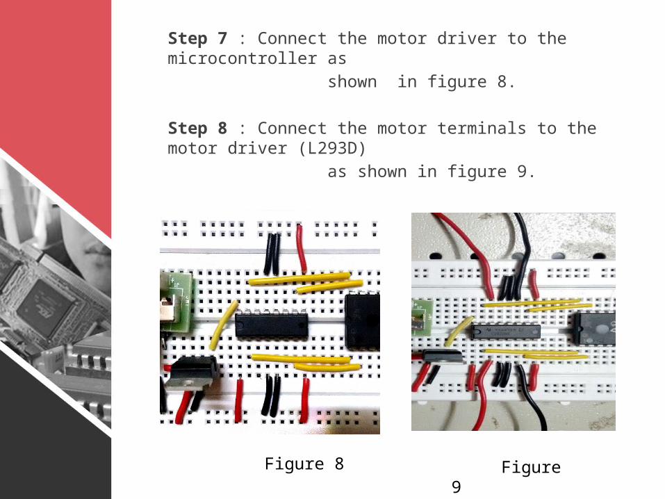
Step 7 : Connect the motor driver to the microcontrol-ler as shown in figure 8.
Step 8 : Connect the motor terminals to the motor driver (L293D) as shown in figure 9.
Figure 9 Figure 8

Step 9 : Load the program to the microcontroller us-ing USB programmer , by inserting the programmer on 5th pin of the microcontroller.
The robot is ready!!

Sample decoder output

Project ImprovisationMotion Detector:If a PIR sensor is integrated to DTMF controlled robot, then it can be used to detect the motion of the warm blood beings.
PIR sensor principle:The PIR sensor has two slots in it where each slot is made of a special material that is sensitive to IR. When the sensor is idle, both slots detect the same amount of IR, the ambient amount radiated from the room or walls or outdoors. When a warm body like a human or animal passes by, it first intercepts one half of the PIR sensor, which causes a positive differential change between the two halves. When the warm body leaves the sensing area, the reverse happens, whereby the sensor generates a negative differential change. These change pulses are what is detected.

Working of PIR sensor PIR sensor

ConstructionStep 1 : Connect the RMC cable to the PIR sensor pins.
Step 2 : Connect the Gnd and Vcc pins accordingly and the output pin to the microcontroller(any pin of your choice).
Step 3 : Connect a buzzer so that if the sensor detects any motion of objects, the buzzer will buzz.
Step 4 : Load the program and the motion detector robot is ready!