PRIUS PRIME PRIUS PHV - Toyota · 2018-06-22 · PRIUS PRIME, PRIUS PHV to help ensure the high...
48
PRIUS PRIME PRIUS PHV Plug-in Hybrid Gasoline-Electric Hybrid Synergy Drive ZVW52 Series
Transcript of PRIUS PRIME PRIUS PHV - Toyota · 2018-06-22 · PRIUS PRIME, PRIUS PHV to help ensure the high...
PRIUS PRIME PRIUS PHV
Plug-in Hybrid
Gasoline-Electric
Hybrid Synergy Drive
ZVW52 Series

Foreword
This guide was developed to educate and assist dismantlers in the safe handling of Toyota PRIUS
PRIME, PRIUS PHV gasoline-electric hybrid vehicles. PRIUS PRIME, PRIUS PHV dismantling
procedures are similar to other non-hybrid Toyota vehicles with the exception of the high voltage
electrical system. It is important to recognize and understand the high voltage electrical system features
and specifications of the Toyota PRIUS PRIME, PRIUS PHV, as they may not be familiar to
dismantlers.
High voltage electricity powers the A/C compressor, electric motor, generator, and inverter/converter.
All other conventional automotive electrical devices such as the head lights, radio, and gauges are
powered from a separate 12 Volt auxiliary battery. Numerous safeguards have been designed into the
PRIUS PRIME, PRIUS PHV to help ensure the high voltage, approximately 351.5 Volt, Lithium-ion
(Li-ion) Hybrid Vehicle (HV) battery pack is kept safe and secure in an accident.
The Li-ion HV battery pack contains sealed batteries that are similar to rechargeable batteries used in
some battery operated power tools and other consumer products. The electrolyte is absorbed in the cell
plates and will not normally leak out even if the battery is cracked. In the unlikely event the electrolyte
does leak, it can be easily neutralized with a dilute boric acid solution or vinegar.
High voltage cables, identifiable by orange insulation and connectors, are isolated from the metal chassis
of the vehicle.
Additional topics contained in the guide include:
Toyota PRIUS PRIME, PRIUS PHV identification.
Major hybrid component locations and descriptions.
By following the information in this guide, dismantlers will be able to handle PRIUS PRIME, PRIUS
PHV hybrid-electric vehicles as safely as the dismantling of a conventional gasoline engine automobile.
2016 Toyota Motor Corporation All rights reserved. This book may not be reproduced or copied, in whole or in part, without the written permission of Toyota Motor Corporation.

Table of Contents
About the PRIUS PRIME, PRIUS PHV................................................................................................... 1
PRIUS PRIME, PRIUS PHV Identification............................................................................................. 2 Exterior ........................................................................................................................................................ 3 Interior ......................................................................................................................................................... 4 Engine Compartment .................................................................................................................................. 5
Hybrid Component Locations & Descriptions ......................................................................................... 6 Specifications .............................................................................................................................................. 7
Hybrid Synergy Drive Operation .............................................................................................................. 8 Vehicle Operation ........................................................................................................................................ 8
Hybrid Vehicle (HV) Battery Pack and Auxiliary Battery...................................................................... 9 HV Battery Pack .......................................................................................................................................... 9 Components Powered by the HV Battery Pack ........................................................................................... 9 HV Battery Pack Recycling ....................................................................................................................... 10 Auxiliary Battery ........................................................................................................................................ 10
High Voltage Safety .................................................................................................................................. 11 High Voltage Safety System ...................................................................................................................... 11 Service Plug Grip ...................................................................................................................................... 12
Precaution to be observed when dismantling the vehicle ...................................................................... 13 Necessary Items ....................................................................................................................................... 13
Spills .......................................................................................................................................................... 14
Dismantling the vehicle ............................................................................................................................ 15
Removal of HV battery ............................................................................................................................ 20

1
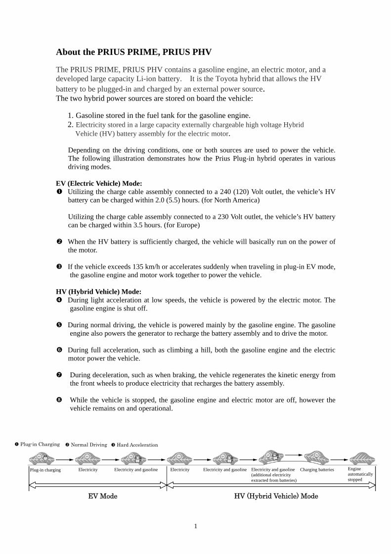
About the PRIUS PRIME, PRIUS PHV The PRIUS PRIME, PRIUS PHV contains a gasoline engine, an electric motor, and a developed large capacity Li-ion battery. It is the Toyota hybrid that allows the HV battery to be plugged-in and charged by an external power source. The two hybrid power sources are stored on board the vehicle:
1. Gasoline stored in the fuel tank for the gasoline engine. 2. Electricity stored in a large capacity externally chargeable high voltage Hybrid
Vehicle (HV) battery assembly for the electric motor.
Depending on the driving conditions, one or both sources are used to power the vehicle. The following illustration demonstrates how the Prius Plug-in hybrid operates in various driving modes.
EV (Electric Vehicle) Mode: Utilizing the charge cable assembly connected to a 240 (120) Volt outlet, the vehicle’s HV
battery can be charged within 2.0 (5.5) hours. (for North America) Utilizing the charge cable assembly connected to a 230 Volt outlet, the vehicle’s HV battery can be charged within 3.5 hours. (for Europe)
When the HV battery is sufficiently charged, the vehicle will basically run on the power of the motor.
If the vehicle exceeds 135 km/h or accelerates suddenly when traveling in plug-in EV mode, the gasoline engine and motor work together to power the vehicle.
HV (Hybrid Vehicle) Mode: During light acceleration at low speeds, the vehicle is powered by the electric motor. The
gasoline engine is shut off.
During normal driving, the vehicle is powered mainly by the gasoline engine. The gasoline engine also powers the generator to recharge the battery assembly and to drive the motor.
During full acceleration, such as climbing a hill, both the gasoline engine and the electric
motor power the vehicle.
During deceleration, such as when braking, the vehicle regenerates the kinetic energy from the front wheels to produce electricity that recharges the battery assembly.
While the vehicle is stopped, the gasoline engine and electric motor are off, however the
vehicle remains on and operational.
Hard Acceleration Normal Driving
EV Mode HV (Hybrid Vehicle) Mode
Plug-in Charging
Plug-in charging Electricity Electricity and gasoline Electricity Electricity and gasoline Electricity and gasoline (additional electricity extracted from batteries)
Charging batteries Engine automatically stopped
2
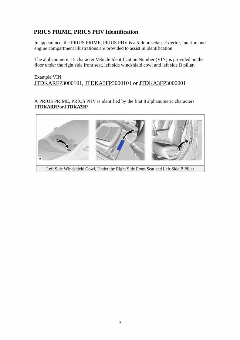
PRIUS PRIME, PRIUS PHV Identification In appearance, the PRIUS PRIME, PRIUS PHV is a 5-door sedan. Exterior, interior, and engine compartment illustrations are provided to assist in identification. The alphanumeric 15 character Vehicle Identification Number (VIN) is provided on the floor under the right side front seat, left side windshield cowl and left side B pillar. Example VIN: JTDKARFP3000101, JTDKA3FP3000101 or JTDKA3FP3000001 A PRIUS PRIME, PRIUS PHV is identified by the first 8 alphanumeric characters JTDKARFP or JTDKA3FP.
Left Side Windshield Cowl, Under the Right Side Front Seat and Left Side B Pillar
3
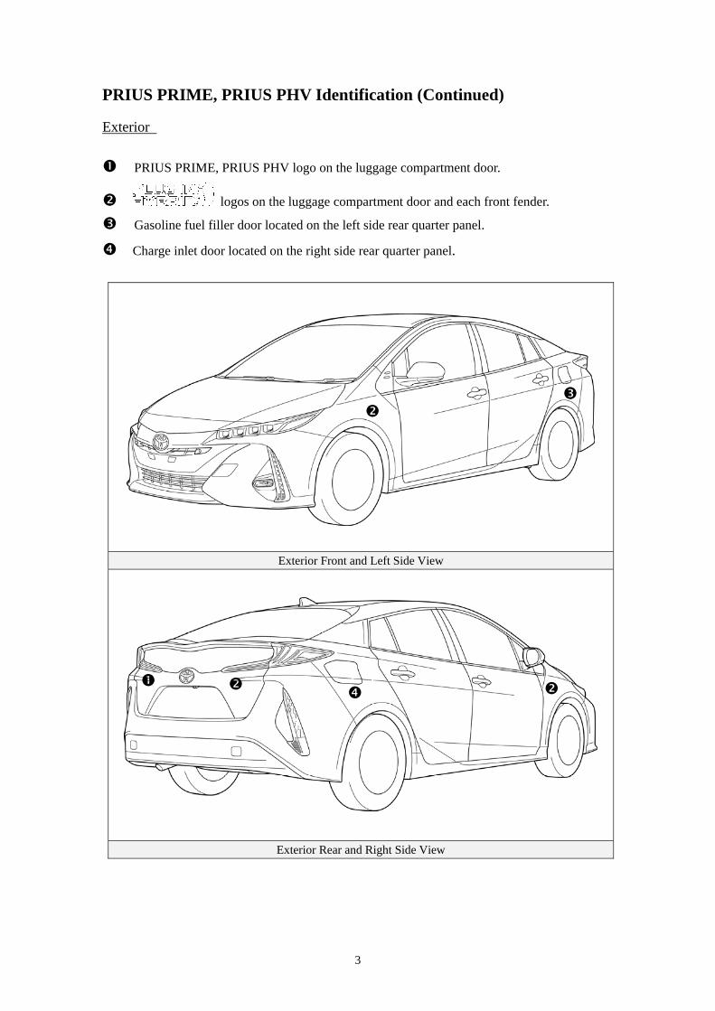
PRIUS PRIME, PRIUS PHV Identification (Continued) Exterior
PRIUS PRIME, PRIUS PHV logo on the luggage compartment door.
logos on the luggage compartment door and each front fender.
Gasoline fuel filler door located on the left side rear quarter panel.
Charge inlet door located on the right side rear quarter panel.
Exterior Front and Left Side View
Exterior Rear and Right Side View
4
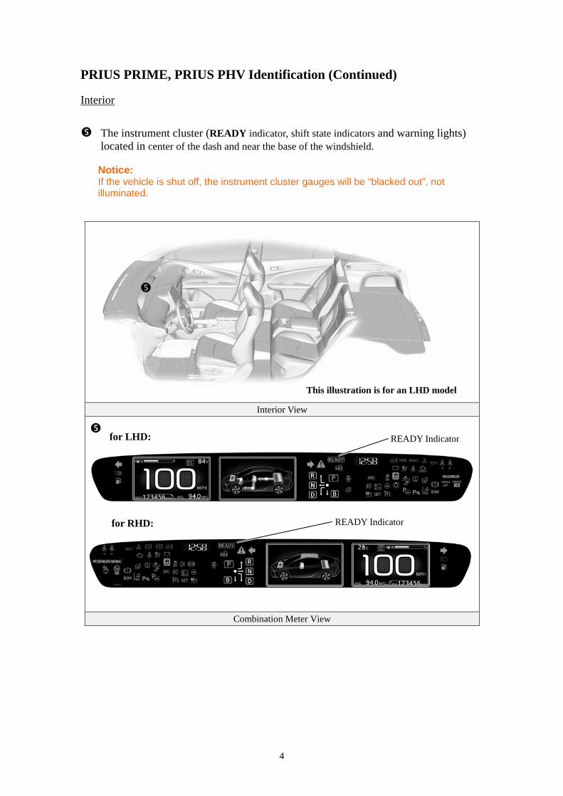
PRIUS PRIME, PRIUS PHV Identification (Continued) Interior
The instrument cluster (READY indicator, shift state indicators and warning lights) located in center of the dash and near the base of the windshield.
Notice: If the vehicle is shut off, the instrument cluster gauges will be “blacked out”, not illuminated.
Interior View
Combination Meter View
This illustration is for an LHD model
READY Indicator
for LHD: READY Indicator
for RHD:
5
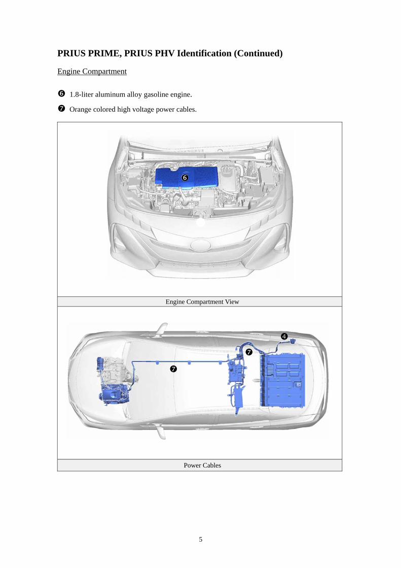
PRIUS PRIME, PRIUS PHV Identification (Continued) Engine Compartment
1.8-liter aluminum alloy gasoline engine.
Orange colored high voltage power cables.
Engine Compartment View
Power Cables
6
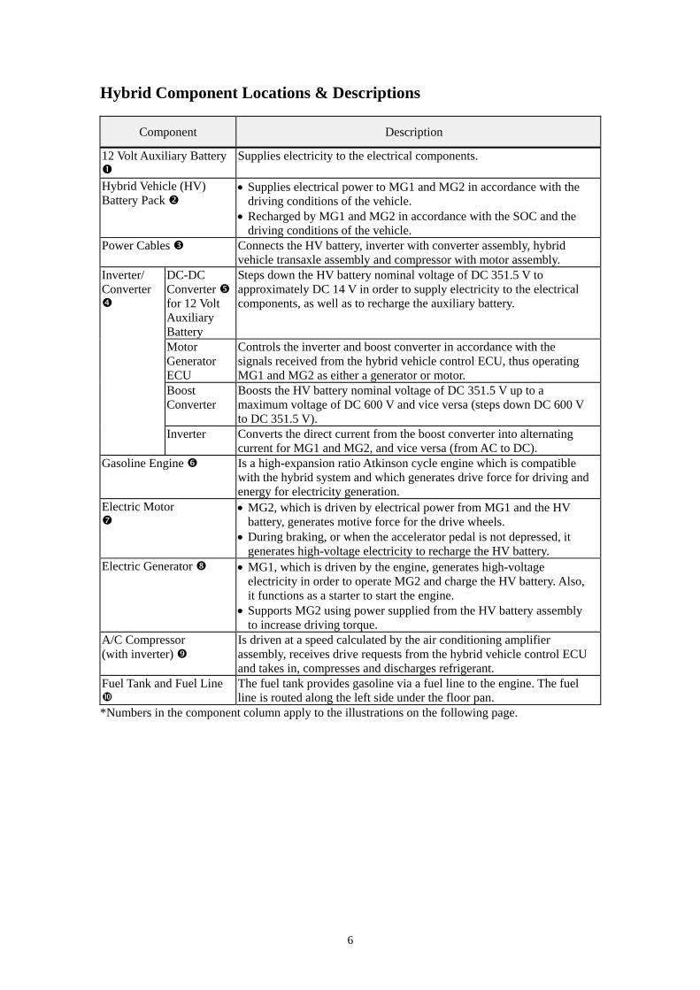
Hybrid Component Locations & Descriptions
Component Description
12 Volt Auxiliary Battery
Supplies electricity to the electrical components.
Hybrid Vehicle (HV) Battery Pack
Supplies electrical power to MG1 and MG2 in accordance with the driving conditions of the vehicle.
Recharged by MG1 and MG2 in accordance with the SOC and the driving conditions of the vehicle.
Power Cables Connects the HV battery, inverter with converter assembly, hybrid vehicle transaxle assembly and compressor with motor assembly.
Inverter/ Converter
DC-DC Converter for 12 Volt Auxiliary Battery
Steps down the HV battery nominal voltage of DC 351.5 V to approximately DC 14 V in order to supply electricity to the electrical components, as well as to recharge the auxiliary battery.
Motor Generator ECU
Controls the inverter and boost converter in accordance with the signals received from the hybrid vehicle control ECU, thus operating MG1 and MG2 as either a generator or motor.
Boost Converter
Boosts the HV battery nominal voltage of DC 351.5 V up to a maximum voltage of DC 600 V and vice versa (steps down DC 600 V to DC 351.5 V).
Inverter Converts the direct current from the boost converter into alternating current for MG1 and MG2, and vice versa (from AC to DC).
Gasoline Engine
Is a high-expansion ratio Atkinson cycle engine which is compatible with the hybrid system and which generates drive force for driving and energy for electricity generation.
Electric Motor
MG2, which is driven by electrical power from MG1 and the HV battery, generates motive force for the drive wheels.
During braking, or when the accelerator pedal is not depressed, it generates high-voltage electricity to recharge the HV battery.
Electric Generator MG1, which is driven by the engine, generates high-voltage electricity in order to operate MG2 and charge the HV battery. Also, it functions as a starter to start the engine.
Supports MG2 using power supplied from the HV battery assembly to increase driving torque.
A/C Compressor (with inverter)
Is driven at a speed calculated by the air conditioning amplifier assembly, receives drive requests from the hybrid vehicle control ECU and takes in, compresses and discharges refrigerant.
Fuel Tank and Fuel Line
The fuel tank provides gasoline via a fuel line to the engine. The fuel line is routed along the left side under the floor pan.
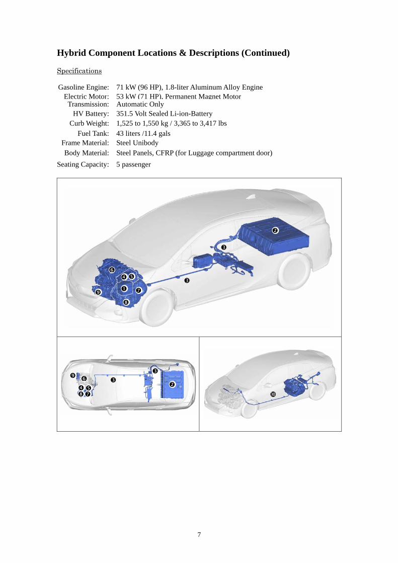
*Numbers in the component column apply to the illustrations on the following page.
7
Hybrid Component Locations & Descriptions (Continued) Specifications Gasoline Engine: 71 kW (96 HP), 1.8-liter Aluminum Alloy Engine
Electric Motor: 53 kW (71 HP), Permanent Magnet MotorTransmission: Automatic Only
HV Battery: 351.5 Volt Sealed Li-ion-Battery Curb Weight: 1,525 to 1,550 kg / 3,365 to 3,417 lbs
Fuel Tank: 43 liters /11.4 gals Frame Material: Steel Unibody Body Material: Steel Panels, CFRP (for Luggage compartment door)
Seating Capacity: 5 passenger
8
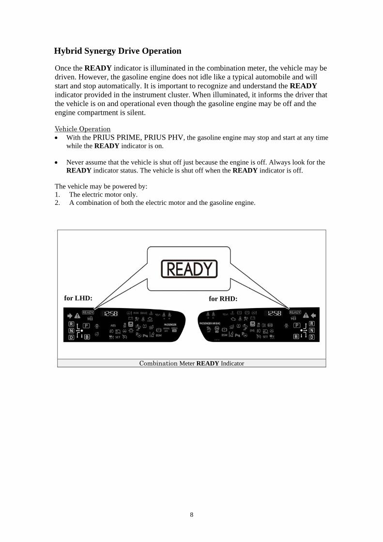
Hybrid Synergy Drive Operation Once the READY indicator is illuminated in the combination meter, the vehicle may be driven. However, the gasoline engine does not idle like a typical automobile and will start and stop automatically. It is important to recognize and understand the READY indicator provided in the instrument cluster. When illuminated, it informs the driver that the vehicle is on and operational even though the gasoline engine may be off and the engine compartment is silent. Vehicle Operation With the PRIUS PRIME, PRIUS PHV, the gasoline engine may stop and start at any time
while the READY indicator is on. Never assume that the vehicle is shut off just because the engine is off. Always look for the
READY indicator status. The vehicle is shut off when the READY indicator is off. The vehicle may be powered by: 1. The electric motor only. 2. A combination of both the electric motor and the gasoline engine.
Combination Meter READY Indicator
for LHD: for RHD:
9
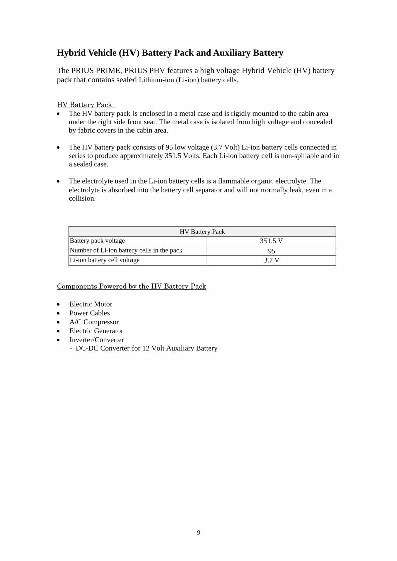
Hybrid Vehicle (HV) Battery Pack and Auxiliary Battery The PRIUS PRIME, PRIUS PHV features a high voltage Hybrid Vehicle (HV) battery pack that contains sealed Lithium-ion (Li-ion) battery cells. HV Battery Pack The HV battery pack is enclosed in a metal case and is rigidly mounted to the cabin area
under the right side front seat. The metal case is isolated from high voltage and concealed by fabric covers in the cabin area.
The HV battery pack consists of 95 low voltage (3.7 Volt) Li-ion battery cells connected in
series to produce approximately 351.5 Volts. Each Li-ion battery cell is non-spillable and in a sealed case.
The electrolyte used in the Li-ion battery cells is a flammable organic electrolyte. The
electrolyte is absorbed into the battery cell separator and will not normally leak, even in a collision.
HV Battery Pack Battery pack voltage 351.5 V Number of Li-ion battery cells in the pack 95 Li-ion battery cell voltage 3.7 V
Components Powered by the HV Battery Pack
Electric Motor Power Cables A/C Compressor Electric Generator Inverter/Converter
- DC-DC Converter for 12 Volt Auxiliary Battery
10
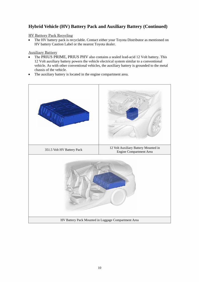
Hybrid Vehicle (HV) Battery Pack and Auxiliary Battery (Continued) HV Battery Pack Recycling The HV battery pack is recyclable. Contact either your Toyota Distributor as mentioned on
HV battery Caution Label or the nearest Toyota dealer. Auxiliary Battery The PRIUS PRIME, PRIUS PHV also contains a sealed lead-acid 12 Volt battery. This
12 Volt auxiliary battery powers the vehicle electrical system similar to a conventional vehicle. As with other conventional vehicles, the auxiliary battery is grounded to the metal chassis of the vehicle.
The auxiliary battery is located in the engine compartment area.
351.5 Volt HV Battery Pack 12 Volt Auxiliary Battery Mounted in
Engine Compartment Area
HV Battery Pack Mounted in Luggage Compartment Area
11
High Voltage Safety The HV battery pack powers the high voltage electrical system with DC electricity. Positive and negative orange colored high voltage power cables are routed from the battery pack, under the vehicle floor pan, to the inverter/converter. The inverter/converter contains a circuit that boosts the HV battery voltage from 351.5 to 600 Volts DC. The inverter/converter creates 3-phase AC to power the motor. Power cables are routed from the inverter/converter to each high voltage motors (electric motor and electric generator). The following systems are intended to help keep occupants in the vehicle and emergency responders safe from high voltage electricity: High Voltage Safety System A high voltage fuse * provides short circuit protection in the HV battery pack. Positive and negative high voltage power cables * connected to the HV battery pack are
controlled by 12 Volt normally open relays *. When the vehicle is shut off, the relays stop electricity flow from leaving the HV battery pack.
WARNING: ・ The high voltage system may remain powered for up to 10
minutes after the vehicle is shut off or disabled. To prevent serious injury or death from severe burns or electric shock, avoid touching, cutting, or opening any orange high voltage power cable or high voltage component.
Both positive and negative power cables * are insulated from the metal body. High
voltage electricity flows through these cables and not through the metal vehicle body. The metal vehicle body is safe to touch because it is insulated from the high voltage components.
A ground fault monitor * continuously monitors for high voltage leakage to the metal
chassis while the vehicle is running. If a malfunction is detected, the hybrid vehicle
computer * will illuminate the master warning light in the instrument cluster and a message indicating that the hybrid system is malfunctioning will be displayed on the multi-information display.
The HV battery pack relays will automatically open to stop electricity flow in a collision
sufficient to activate the SRS. *Numbers apply to the illustration on the following page.
12
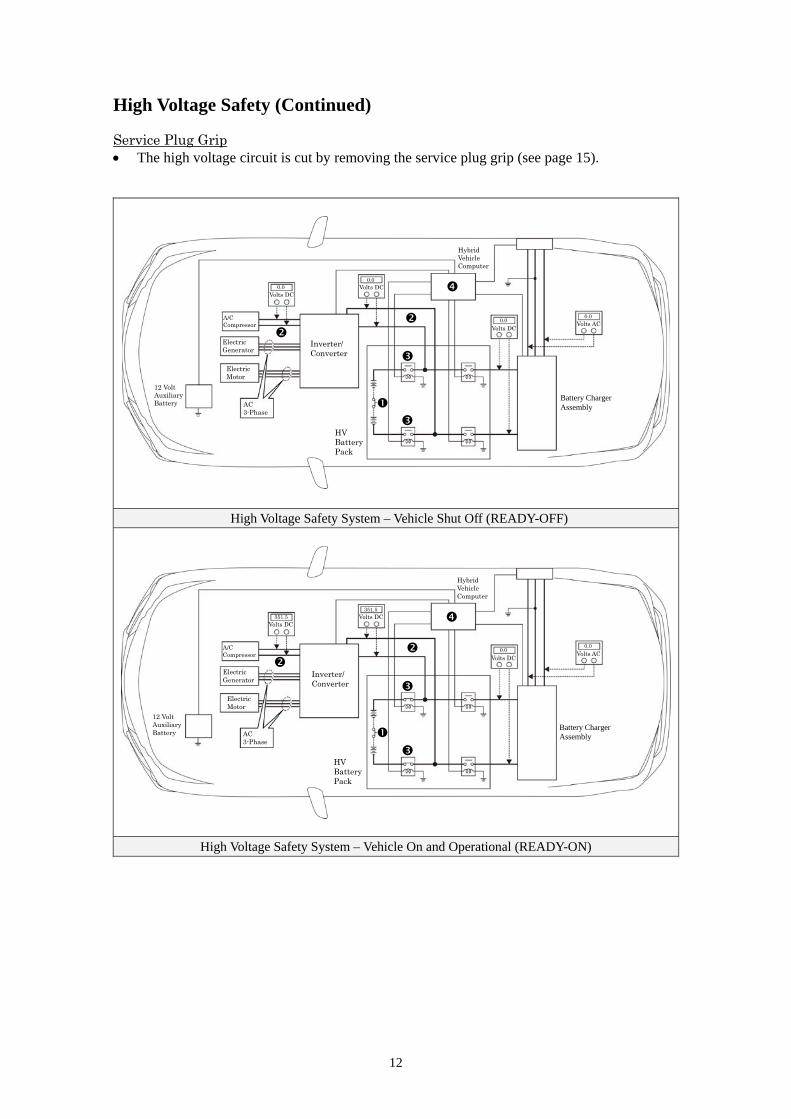
High Voltage Safety (Continued) Service Plug Grip The high voltage circuit is cut by removing the service plug grip (see page 15).
High Voltage Safety System – Vehicle Shut Off (READY-OFF)
High Voltage Safety System – Vehicle On and Operational (READY-ON)
A/C Compressor
Electric Generator
Electric Motor
0.0
0.0
AC 3-Phase
Inverter/ Converter
Volts DC
Volts DC
HV Battery Pack
12 Volt Auxiliary Battery
Hybrid Vehicle Computer
Volts DC 0.0
0.0 Volts AC
Battery Charger Assembly
A/C Compressor
Electric Generator
Electric Motor
351.5
0.0
AC 3-Phase
Inverter/ Converter
Volts DC
Volts DC
HV Battery Pack
12 Volt Auxiliary Battery
Hybrid Vehicle Computer
Volts DC 351.5
0.0
Volts AC
Battery Charger Assembly
13
Precaution to be observed when dismantling the vehicle
WARNING:
・ The high voltage system may remain powered for up to 10
minutes after the vehicle is shut off or disabled. To prevent
serious injury or death from severe burns or electric shock,
avoid touching, cutting, or opening any orange high voltage
power cable or high voltage component.
Necessary Items
Protective clothing such as insulated gloves (electrically insulated), rubber gloves, safety goggles, and safety shoes.
Insulating tape such as electrical tape that has a suitable electrical insulation rating. Before wearing insulated gloves, make sure that they are not cracked, ruptured, torn, or damaged in
any way. Do not wear wet insulated gloves. An electrical tester that is capable of measuring DC 750 Volts or more.

14
Spills The PRIUS PRIME, PRIUS PHV contains the same common automotive fluids used in other
non-hybrid Toyota vehicles, with the exception of the Li-ion electrolyte used in the HV battery pack.
The electrolyte used in the Li-ion battery cells is a flammable organic electrolyte. The electrolyte is
absorbed into the battery cell separators, even if the battery cells are crushed or cracked, it is unlikely
that liquid electrolyte will leak. Any liquid electrolyte that leaks from a Li-ion battery cell quickly
evaporates.
WARNING:
・ The Li-ion battery contains organic electrolyte. Only a small
amount may leak from the batteries which may irritate the eyes,
nose, throat, and skin.
・ Contact with the vapor produced by the electrolyte may irritate the nose and throat.
・ To avoid injury by coming in contact with the electrolyte or vapor,
wear personal protective equipment for organic electrolyte
including SCBA or protective mask for organic gases.
Handle Li-ion electrolyte spills using the following Personal Protective Equipment (PPE):
• Splash shield or safety goggles. A fold down face shield is not acceptable for acid or
electrolyte spills.
• Rubber gloves or gloves suitable for organic solvents.
• Apron suitable for organic solvents.
• Rubber boots or boots suitable for organic solvents.
• Protective mask for organic gases or SCBA.
15
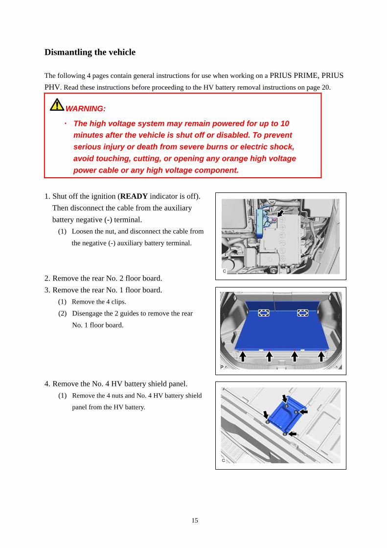
Dismantling the vehicle
The following 4 pages contain general instructions for use when working on a PRIUS PRIME, PRIUS
PHV. Read these instructions before proceeding to the HV battery removal instructions on page 20.
WARNING:
・ The high voltage system may remain powered for up to 10
minutes after the vehicle is shut off or disabled. To prevent
serious injury or death from severe burns or electric shock,
avoid touching, cutting, or opening any orange high voltage
power cable or any high voltage component.
1. Shut off the ignition (READY indicator is off).
Then disconnect the cable from the auxiliary
battery negative (-) terminal.
(1) Loosen the nut, and disconnect the cable from
the negative (-) auxiliary battery terminal.
2. Remove the rear No. 2 floor board.
3. Remove the rear No. 1 floor board.
(1) Remove the 4 clips.
(2) Disengage the 2 guides to remove the rear
No. 1 floor board.
4. Remove the No. 4 HV battery shield panel.
(1) Remove the 4 nuts and No. 4 HV battery shield
panel from the HV battery.

16
5. Remove the service plug grip.
Caution:
・Wear insulated gloves.
・Do not inspect or service the high voltage
system with the service plug grip installed.
・To reduce the risk of electric shock, make sure to remove the service plug grip to
cut off the high voltage circuit before servicing the vehicle..
・To reduce the risk of electric shock, make sure
to wait at least 10 minutes after removing the
service plug grip to fully discharge the high
voltage capacitor inside the inverter with
converter assembly.
・Keep the removed service plug grip in your pocket to prevent other technicians from
accidentally installing it while you are servicing the vehicle.
・Place a "HIGH VOLTAGE WORK IN PROGRESS. DO NOT TOUCH." sign, in order to
prevent other technicians from accidentally reconnecting the power while work is in
progress.
Notice:
・After removing the service plug grip, turning the power switch on (READY) may cause a
malfunction. Do not turn the power switch on (READY) unless instructed by the repair manual.
・Do not touch the terminals of the service plug grip.
Hint:
Waiting for at least 10 minutes is required to discharge the high voltage capacitor inside the
inverter with converter assembly.
17
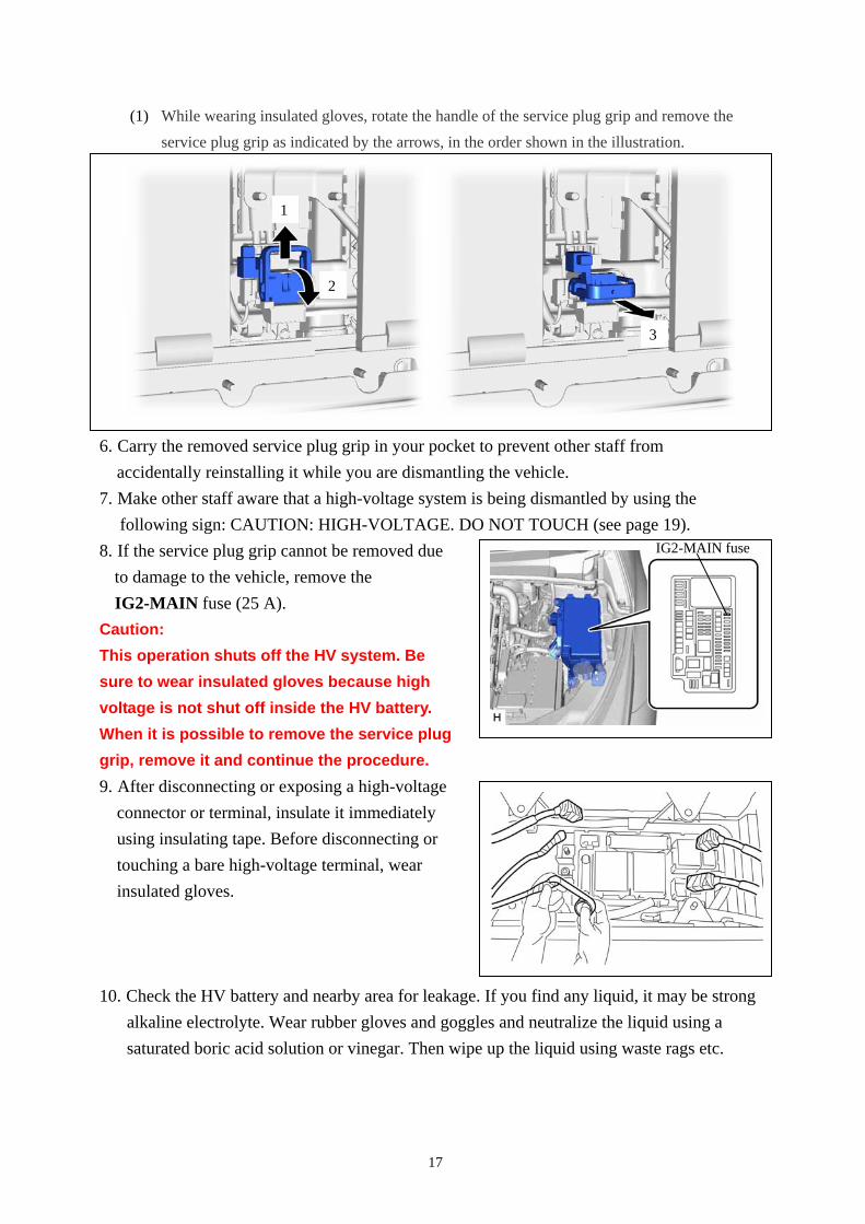
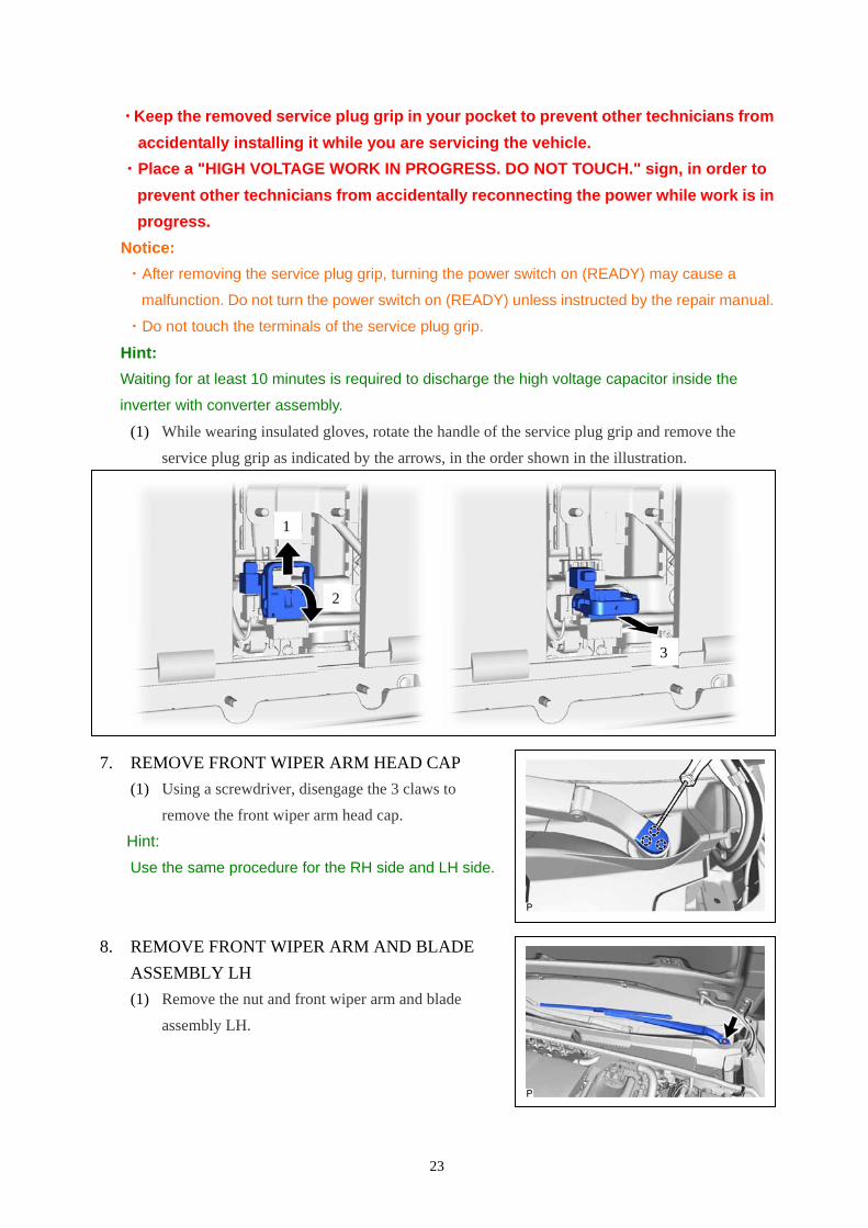
(1) While wearing insulated gloves, rotate the handle of the service plug grip and remove the
service plug grip as indicated by the arrows, in the order shown in the illustration.
6. Carry the removed service plug grip in your pocket to prevent other staff from
accidentally reinstalling it while you are dismantling the vehicle.
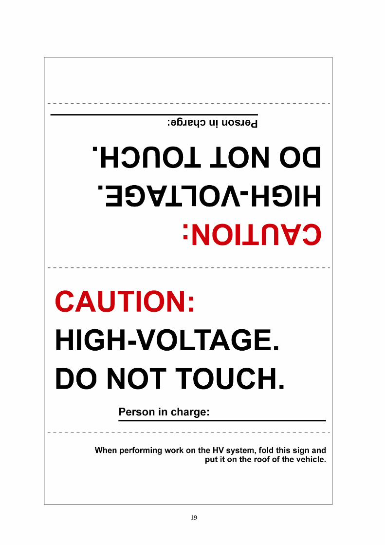
7. Make other staff aware that a high-voltage system is being dismantled by using the
following sign: CAUTION: HIGH-VOLTAGE. DO NOT TOUCH (see page 19).
8. If the service plug grip cannot be removed due
to damage to the vehicle, remove the
IG2-MAIN fuse (25 A).
Caution:
This operation shuts off the HV system. Be
sure to wear insulated gloves because high
voltage is not shut off inside the HV battery.
When it is possible to remove the service plug
grip, remove it and continue the procedure.
9. After disconnecting or exposing a high-voltage
connector or terminal, insulate it immediately
using insulating tape. Before disconnecting or
touching a bare high-voltage terminal, wear
insulated gloves.
10. Check the HV battery and nearby area for leakage. If you find any liquid, it may be strong
alkaline electrolyte. Wear rubber gloves and goggles and neutralize the liquid using a
saturated boric acid solution or vinegar. Then wipe up the liquid using waste rags etc.
IG2-MAIN fuse
1
2
3

18
11. If the electrolyte comes into contact with your skin, wash the skin immediately using a
saturated boric acid solution or a large amount of water. If the electrolyte adheres to any
article of clothing, take the clothing off immediately.
12. If the electrolyte comes into contact with your eye(s), call out loudly for help. Do not
rub your eye(s). Instead, wash the eye(s) with a dilute boric acid solution or a large
amount of water and seek medical care.
13. With the exception of the HV battery, remove parts by following procedures which are
similar to conventional Toyota vehicles. For the removal of the HV battery, refer to the
following pages.
19
20
Removal of HV battery
WARNING:
・ Be sure to wear insulated gloves when handling high-voltage
parts.
・ Even if the vehicle is shut off and the relays are off, be sure to
remove the service plug grip before performing any further
work.
・ Power remains in the high voltage electrical system for 10
minutes even after the HV battery pack is shut off because the
circuit has a condenser that stores power.
・ Make sure that the tester reading is 0 V before touching any
high-voltage terminals which are not insulated.
・ The SRS may remain powered for up to 90 seconds after the
vehicle is shut off or disabled. To prevent serious injury or
death from unintentional SRS deployment, avoid cutting the
SRS components.
・ The solar panels generate electricity with even a small amount
of sunlight. To stop generation of electricity, cover the solar
panels completely with a material that will block sunlight.
(with Solar Charging System)
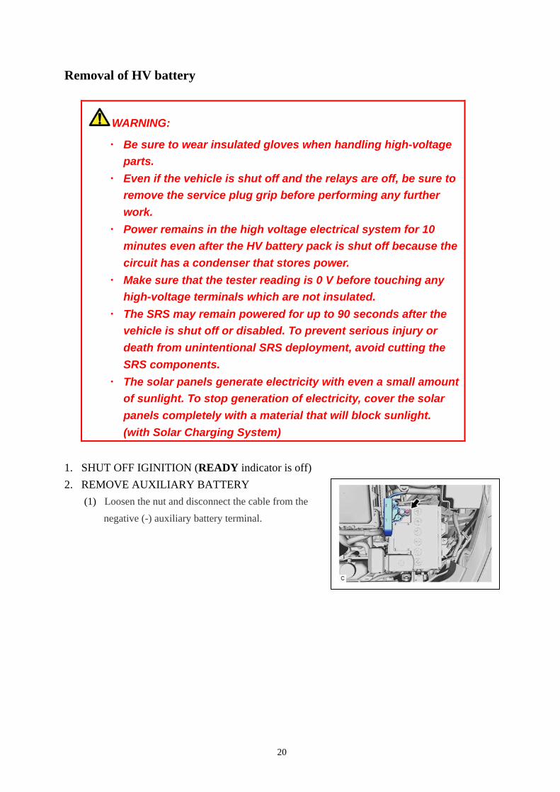
1. SHUT OFF IGINITION (READY indicator is off)
2. REMOVE AUXILIARY BATTERY
(1) Loosen the nut and disconnect the cable from the
negative (-) auxiliary battery terminal.
21
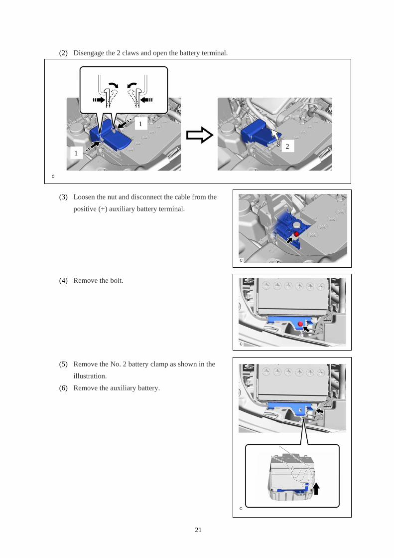
(2) Disengage the 2 claws and open the battery terminal.
(3) Loosen the nut and disconnect the cable from the
positive (+) auxiliary battery terminal.
(4) Remove the bolt.
(5) Remove the No. 2 battery clamp as shown in the
illustration.
(6) Remove the auxiliary battery.
1 2
1
22
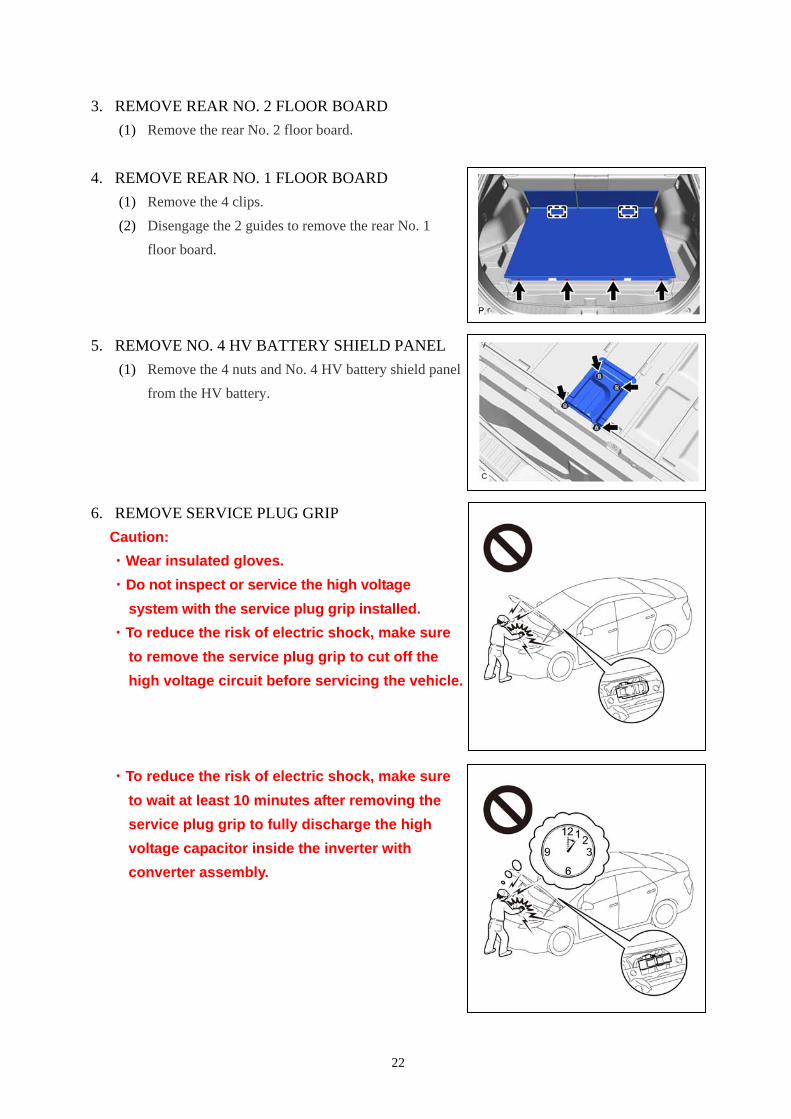
3. REMOVE REAR NO. 2 FLOOR BOARD
(1) Remove the rear No. 2 floor board.
4. REMOVE REAR NO. 1 FLOOR BOARD
(1) Remove the 4 clips.
(2) Disengage the 2 guides to remove the rear No. 1
floor board.
5. REMOVE NO. 4 HV BATTERY SHIELD PANEL
(1) Remove the 4 nuts and No. 4 HV battery shield panel
from the HV battery.
6. REMOVE SERVICE PLUG GRIP
Caution:
・Wear insulated gloves.
・Do not inspect or service the high voltage
system with the service plug grip installed.
・To reduce the risk of electric shock, make sure
to remove the service plug grip to cut off the
high voltage circuit before servicing the vehicle.
・To reduce the risk of electric shock, make sure
to wait at least 10 minutes after removing the
service plug grip to fully discharge the high
voltage capacitor inside the inverter with
converter assembly.
23
・Keep the removed service plug grip in your pocket to prevent other technicians from
accidentally installing it while you are servicing the vehicle.
・Place a "HIGH VOLTAGE WORK IN PROGRESS. DO NOT TOUCH." sign, in order to
prevent other technicians from accidentally reconnecting the power while work is in
progress.
Notice:
・After removing the service plug grip, turning the power switch on (READY) may cause a
malfunction. Do not turn the power switch on (READY) unless instructed by the repair manual.
・Do not touch the terminals of the service plug grip.
Hint:
Waiting for at least 10 minutes is required to discharge the high voltage capacitor inside the
inverter with converter assembly.
(1) While wearing insulated gloves, rotate the handle of the service plug grip and remove the
service plug grip as indicated by the arrows, in the order shown in the illustration.
7. REMOVE FRONT WIPER ARM HEAD CAP
(1) Using a screwdriver, disengage the 3 claws to
remove the front wiper arm head cap.
Hint:
Use the same procedure for the RH side and LH side.
8. REMOVE FRONT WIPER ARM AND BLADE
ASSEMBLY LH
(1) Remove the nut and front wiper arm and blade
assembly LH.
2
1
3
24
9. REMOVE FRONT WIPER ARM AND BLADE
ASSEMBLY RH
(1) Remove the nut and front wiper arm and blade
assembly RH.
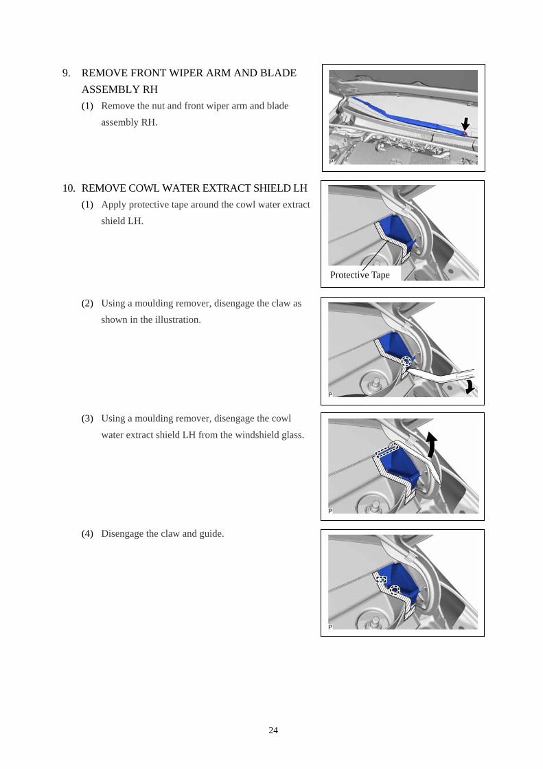
10. REMOVE COWL WATER EXTRACT SHIELD LH
(1) Apply protective tape around the cowl water extract
shield LH.
(2) Using a moulding remover, disengage the claw as
shown in the illustration.
(3) Using a moulding remover, disengage the cowl
water extract shield LH from the windshield glass.
(4) Disengage the claw and guide.
Protective Tape
25
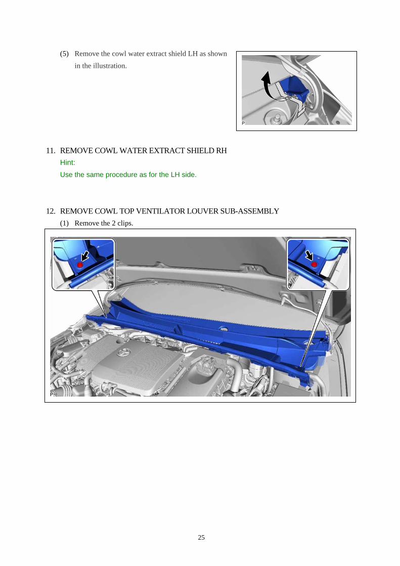
(5) Remove the cowl water extract shield LH as shown
in the illustration.
11. REMOVE COWL WATER EXTRACT SHIELD RH
Hint:
Use the same procedure as for the LH side.
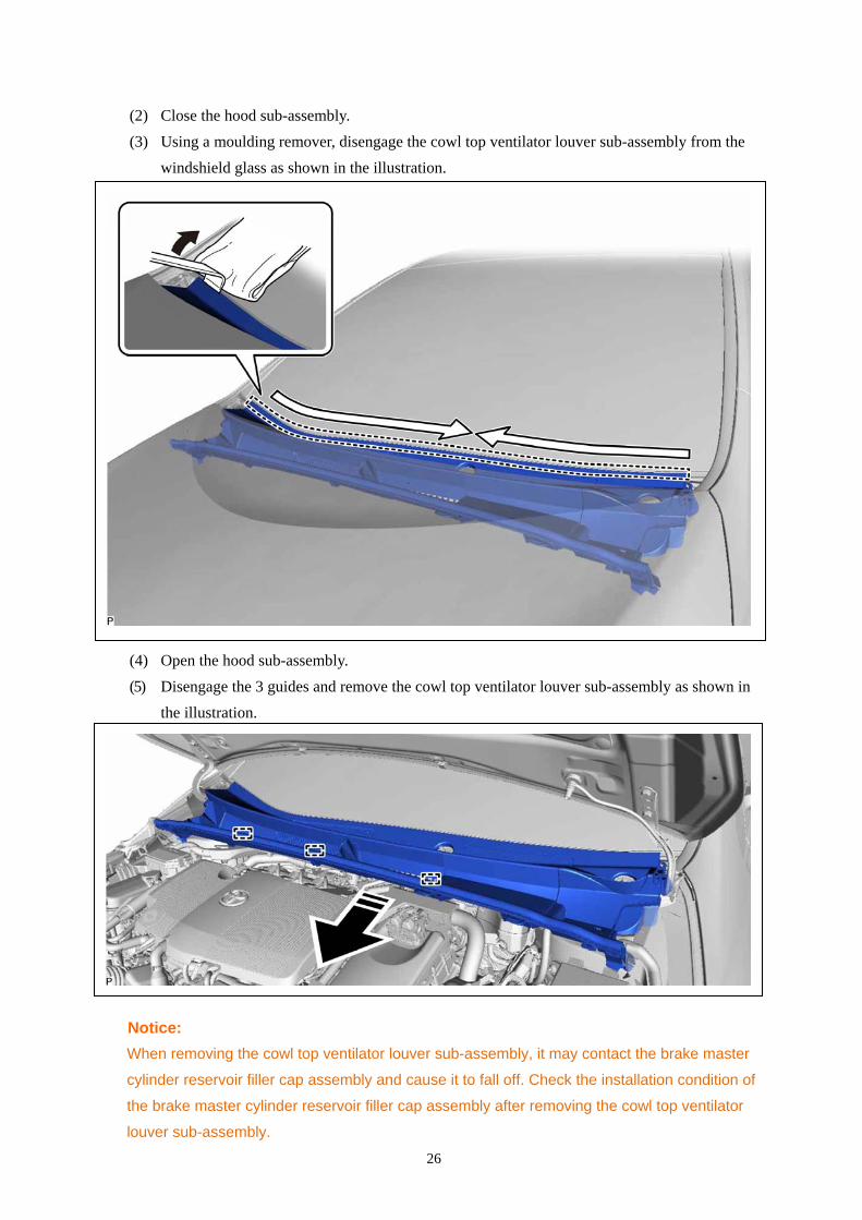
12. REMOVE COWL TOP VENTILATOR LOUVER SUB-ASSEMBLY
(1) Remove the 2 clips.
26
(2) Close the hood sub-assembly.
(3) Using a moulding remover, disengage the cowl top ventilator louver sub-assembly from the
windshield glass as shown in the illustration.
(4) Open the hood sub-assembly.
(5) Disengage the 3 guides and remove the cowl top ventilator louver sub-assembly as shown in
the illustration.
Notice:
When removing the cowl top ventilator louver sub-assembly, it may contact the brake master
cylinder reservoir filler cap assembly and cause it to fall off. Check the installation condition of
the brake master cylinder reservoir filler cap assembly after removing the cowl top ventilator
louver sub-assembly.
27
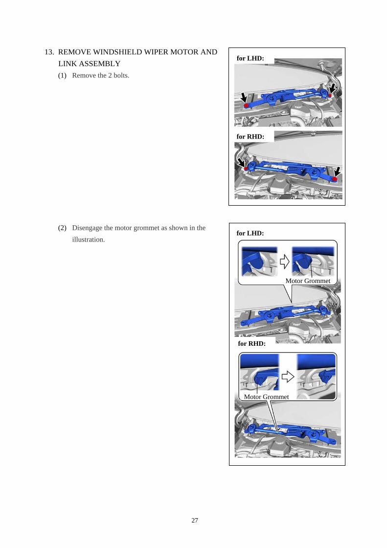
13. REMOVE WINDSHIELD WIPER MOTOR AND
LINK ASSEMBLY
(1) Remove the 2 bolts.
(2) Disengage the motor grommet as shown in the
illustration.
Motor Grommet
for LHD:
for RHD:
for LHD:
for RHD:
Motor Grommet
28
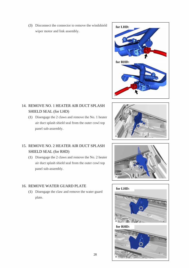
(3) Disconnect the connector to remove the windshield
wiper motor and link assembly.
14. REMOVE NO. 1 HEATER AIR DUCT SPLASH
SHIELD SEAL (for LHD)
(1) Disengage the 2 claws and remove the No. 1 heater
air duct splash shield seal from the outer cowl top
panel sub-assembly.
15. REMOVE NO. 2 HEATER AIR DUCT SPLASH
SHIELD SEAL (for RHD)
(1) Disengage the 2 claws and remove the No. 2 heater
air duct splash shield seal from the outer cowl top
panel sub-assembly.
16. REMOVE WATER GUARD PLATE
(1) Disengage the claw and remove the water guard
plate.
for LHD:
for RHD:
for LHD:
for RHD:
29
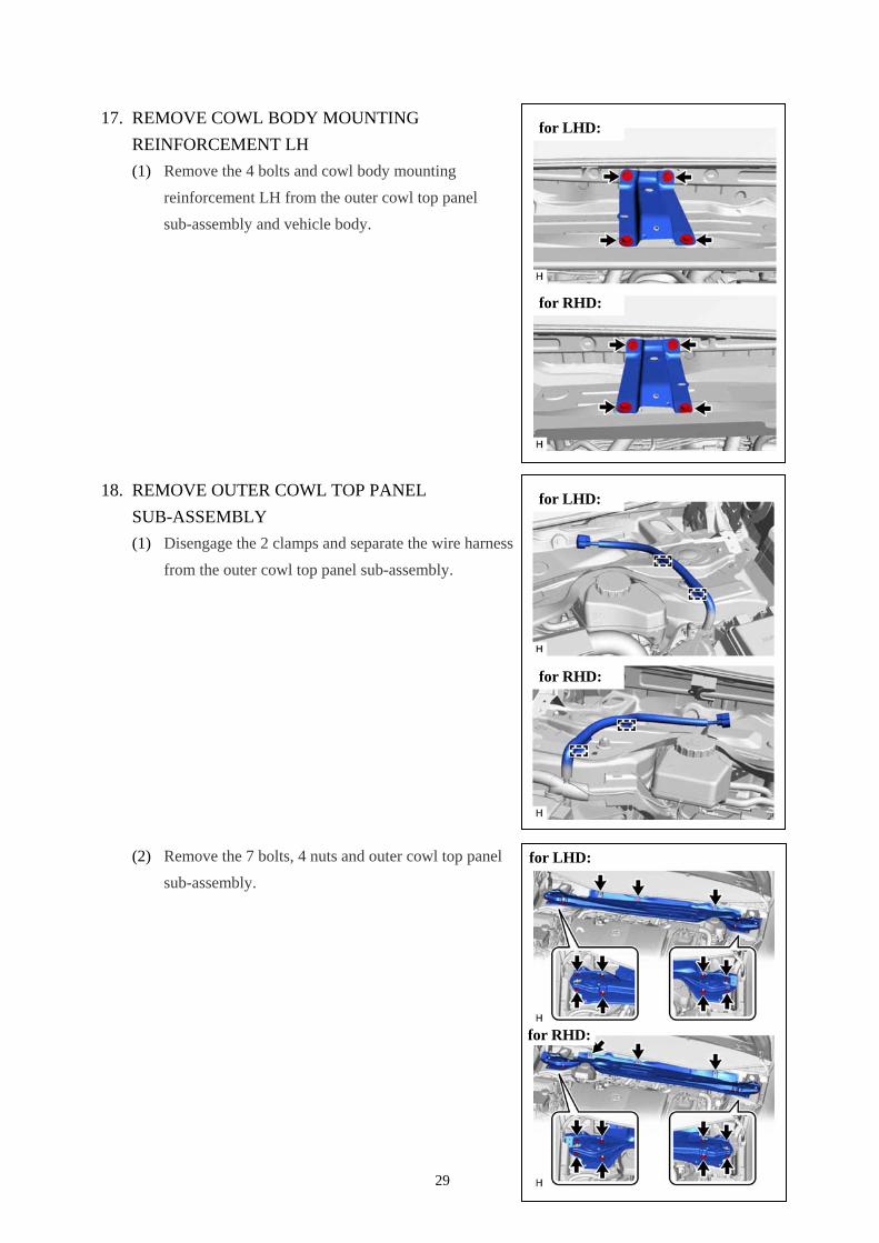
17. REMOVE COWL BODY MOUNTING
REINFORCEMENT LH
(1) Remove the 4 bolts and cowl body mounting
reinforcement LH from the outer cowl top panel
sub-assembly and vehicle body.
18. REMOVE OUTER COWL TOP PANEL
SUB-ASSEMBLY
(1) Disengage the 2 clamps and separate the wire harness
from the outer cowl top panel sub-assembly.
(2) Remove the 7 bolts, 4 nuts and outer cowl top panel
sub-assembly.
for LHD:
for RHD:
for LHD:
for RHD:
for LHD:
for RHD:
30
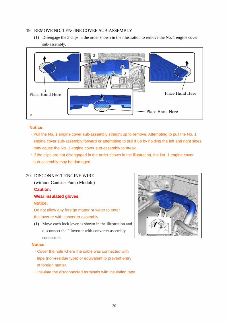
19. REMOVE NO. 1 ENGINE COVER SUB-ASSEMBLY
(1) Disengage the 3 clips in the order shown in the illustration to remove the No. 1 engine cover
sub-assembly.
Notice:
・Pull the No. 1 engine cover sub-assembly straight up to remove. Attempting to pull the No. 1
engine cover sub-assembly forward or attempting to pull it up by holding the left and right sides
may cause the No. 1 engine cover sub-assembly to break.
・If the clips are not disengaged in the order shown in the illustration, the No. 1 engine cover
sub-assembly may be damaged.
20. DISCONNECT ENGINE WIRE
(without Canister Pump Module)
Caution:
Wear insulated gloves.
Notice:
Do not allow any foreign matter or water to enter
the inverter with converter assembly.
(1) Move each lock lever as shown in the illustration and
disconnect the 2 inverter with converter assembly
connectors.
Notice:
・Cover the hole where the cable was connected with
tape (non-residue type) or equivalent to prevent entry
of foreign matter.
・Insulate the disconnected terminals with insulating tape.
2
1
3
Place Hand Here
Place Hand HerePlace Hand Here
31
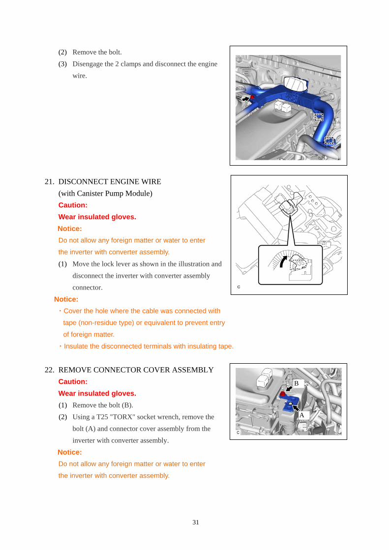
(2) Remove the bolt.
(3) Disengage the 2 clamps and disconnect the engine
wire.
21. DISCONNECT ENGINE WIRE
(with Canister Pump Module)
Caution:
Wear insulated gloves.
Notice:
Do not allow any foreign matter or water to enter
the inverter with converter assembly.
(1) Move the lock lever as shown in the illustration and
disconnect the inverter with converter assembly
connector.
Notice:
・Cover the hole where the cable was connected with
tape (non-residue type) or equivalent to prevent entry
of foreign matter.
・Insulate the disconnected terminals with insulating tape.
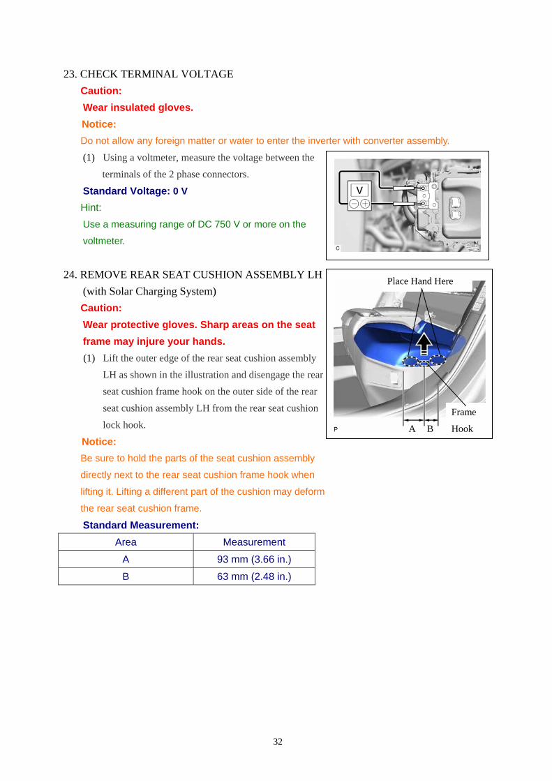
22. REMOVE CONNECTOR COVER ASSEMBLY
Caution:
Wear insulated gloves.
(1) Remove the bolt (B).
(2) Using a T25 "TORX" socket wrench, remove the
bolt (A) and connector cover assembly from the
inverter with converter assembly.
Notice:
Do not allow any foreign matter or water to enter
the inverter with converter assembly.
A
B
32
23. CHECK TERMINAL VOLTAGE
Caution:
Wear insulated gloves.
Notice:
Do not allow any foreign matter or water to enter the inverter with converter assembly.
(1) Using a voltmeter, measure the voltage between the
terminals of the 2 phase connectors.
Standard Voltage: 0 V
Hint:
Use a measuring range of DC 750 V or more on the
voltmeter.
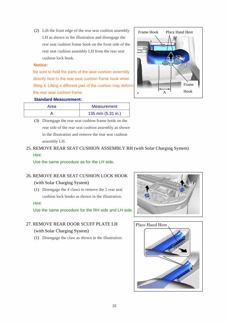
24. REMOVE REAR SEAT CUSHION ASSEMBLY LH
(with Solar Charging System)
Caution:
Wear protective gloves. Sharp areas on the seat
frame may injure your hands.
(1) Lift the outer edge of the rear seat cushion assembly
LH as shown in the illustration and disengage the rear
seat cushion frame hook on the outer side of the rear
seat cushion assembly LH from the rear seat cushion
lock hook.
Notice:
Be sure to hold the parts of the seat cushion assembly
directly next to the rear seat cushion frame hook when
lifting it. Lifting a different part of the cushion may deform
the rear seat cushion frame.
Standard Measurement:
Area Measurement
A 93 mm (3.66 in.)
B 63 mm (2.48 in.)
A
Frame
HookB
Place Hand Here
33
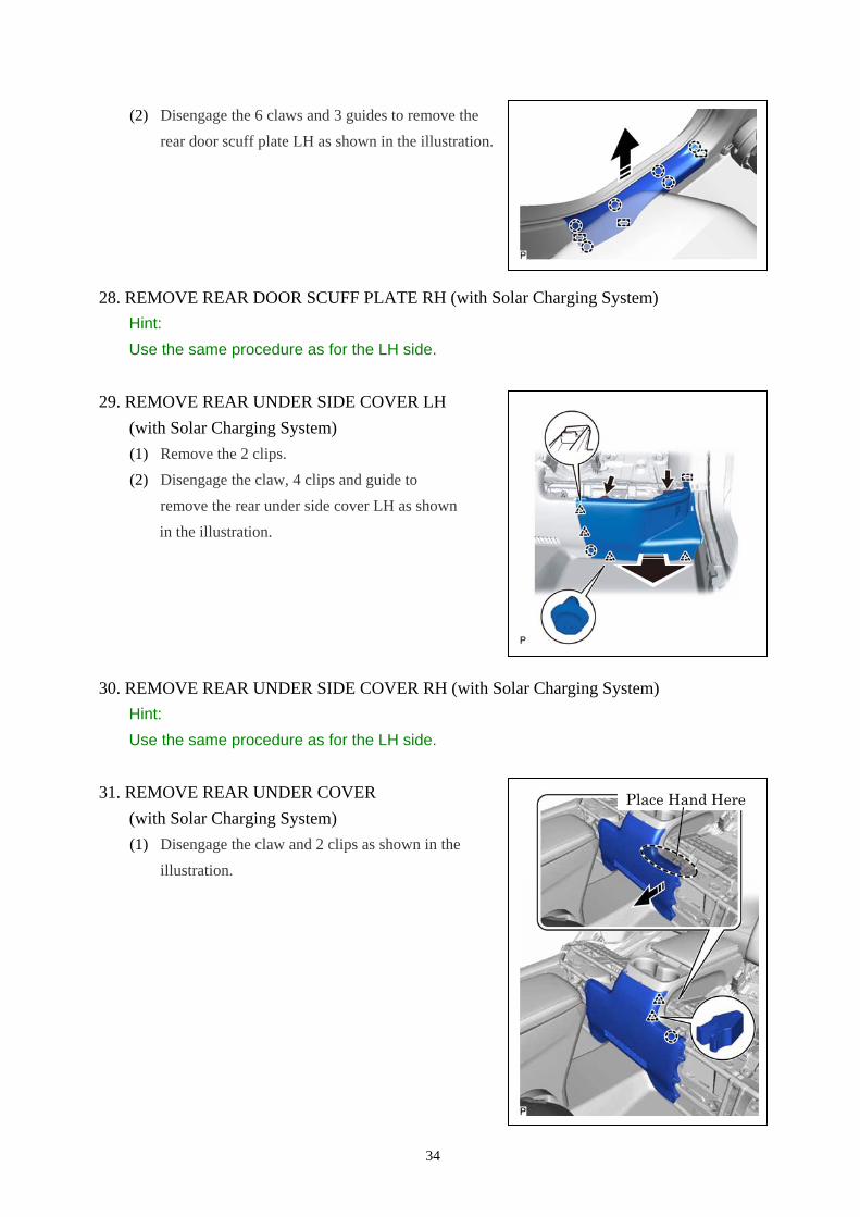
(2) Lift the front edge of the rear seat cushion assembly
LH as shown in the illustration and disengage the
rear seat cushion frame hook on the front side of the
rear seat cushion assembly LH from the rear seat
cushion lock hook.
Notice:
Be sure to hold the parts of the seat cushion assembly
directly next to the rear seat cushion frame hook when
lifting it. Lifting a different part of the cushion may deform
the rear seat cushion frame.
Standard Measurement:
Area Measurement
A 135 mm (5.31 in.)
(3) Disengage the rear seat cushion frame hook on the
rear side of the rear seat cushion assembly as shown
in the illustration and remove the rear seat cushion
assembly LH.
25. REMOVE REAR SEAT CUSHION ASSEMBLY RH (with Solar Charging System)
Hint:
Use the same procedure as for the LH side.
26. REMOVE REAR SEAT CUSHION LOCK HOOK
(with Solar Charging System)
(1) Disengage the 4 claws to remove the 2 rear seat
cushion lock hooks as shown in the illustration.
Hint:
Use the same procedure for the RH side and LH side.
27. REMOVE REAR DOOR SCUFF PLATE LH
(with Solar Charging System)
(1) Disengage the claw as shown in the illustration.
Place Hand Here
A
Frame
Hook
Frame Hook Place Hand Here
34
(2) Disengage the 6 claws and 3 guides to remove the
rear door scuff plate LH as shown in the illustration.
28. REMOVE REAR DOOR SCUFF PLATE RH (with Solar Charging System)
Hint:
Use the same procedure as for the LH side.
29. REMOVE REAR UNDER SIDE COVER LH
(with Solar Charging System)
(1) Remove the 2 clips.
(2) Disengage the claw, 4 clips and guide to
remove the rear under side cover LH as shown
in the illustration.
30. REMOVE REAR UNDER SIDE COVER RH (with Solar Charging System)
Hint:
Use the same procedure as for the LH side.
31. REMOVE REAR UNDER COVER
(with Solar Charging System)
(1) Disengage the claw and 2 clips as shown in the
illustration.
Place Hand Here
35
(2) Disengage the claw and 3 clips as shown in the
illustration.
(3) Disengage the 2 clips to remove the rear under
cover as shown in the illustration.
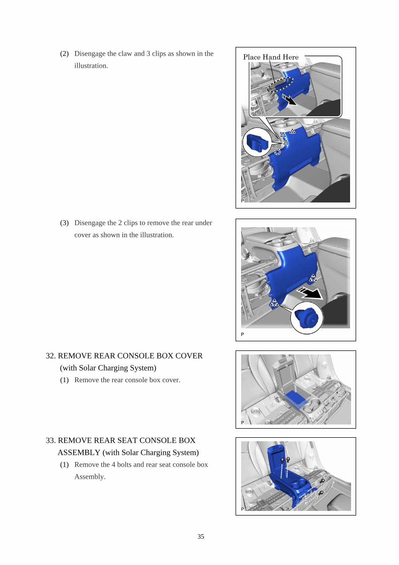
32. REMOVE REAR CONSOLE BOX COVER
(with Solar Charging System)
(1) Remove the rear console box cover.
33. REMOVE REAR SEAT CONSOLE BOX
ASSEMBLY (with Solar Charging System)
(1) Remove the 4 bolts and rear seat console box
Assembly.
Place Hand Here
36
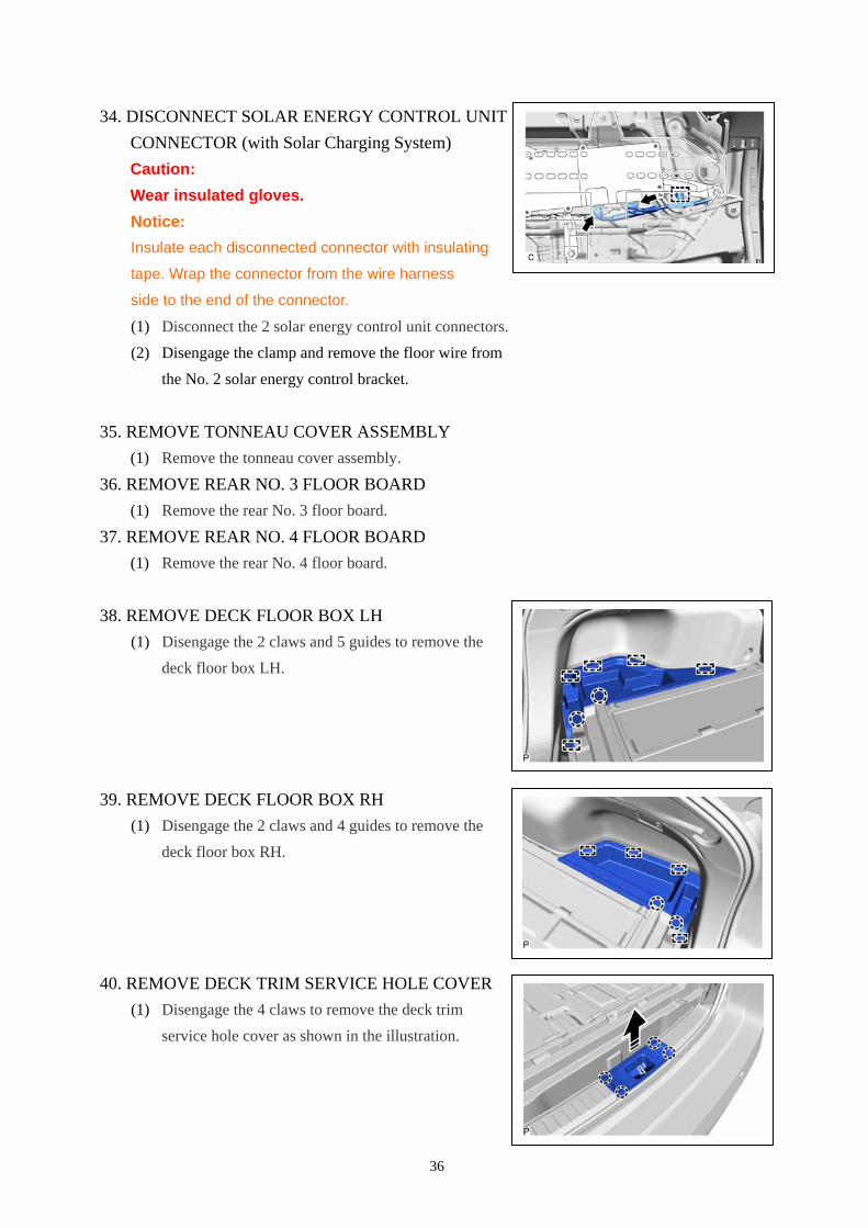
34. DISCONNECT SOLAR ENERGY CONTROL UNIT
CONNECTOR (with Solar Charging System)
Caution:
Wear insulated gloves.
Notice:
Insulate each disconnected connector with insulating
tape. Wrap the connector from the wire harness
side to the end of the connector.
(1) Disconnect the 2 solar energy control unit connectors.
(2) Disengage the clamp and remove the floor wire from
the No. 2 solar energy control bracket.
35. REMOVE TONNEAU COVER ASSEMBLY
(1) Remove the tonneau cover assembly.
36. REMOVE REAR NO. 3 FLOOR BOARD
(1) Remove the rear No. 3 floor board.
37. REMOVE REAR NO. 4 FLOOR BOARD
(1) Remove the rear No. 4 floor board.
38. REMOVE DECK FLOOR BOX LH
(1) Disengage the 2 claws and 5 guides to remove the
deck floor box LH.
39. REMOVE DECK FLOOR BOX RH
(1) Disengage the 2 claws and 4 guides to remove the
deck floor box RH.
40. REMOVE DECK TRIM SERVICE HOLE COVER
(1) Disengage the 4 claws to remove the deck trim
service hole cover as shown in the illustration.
37
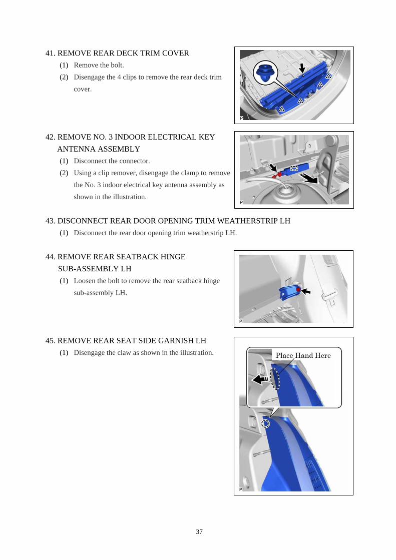
41. REMOVE REAR DECK TRIM COVER
(1) Remove the bolt.
(2) Disengage the 4 clips to remove the rear deck trim
cover.
42. REMOVE NO. 3 INDOOR ELECTRICAL KEY
ANTENNA ASSEMBLY
(1) Disconnect the connector.
(2) Using a clip remover, disengage the clamp to remove
the No. 3 indoor electrical key antenna assembly as
shown in the illustration.
43. DISCONNECT REAR DOOR OPENING TRIM WEATHERSTRIP LH
(1) Disconnect the rear door opening trim weatherstrip LH.
44. REMOVE REAR SEATBACK HINGE
SUB-ASSEMBLY LH
(1) Loosen the bolt to remove the rear seatback hinge
sub-assembly LH.
45. REMOVE REAR SEAT SIDE GARNISH LH
(1) Disengage the claw as shown in the illustration.
Place Hand Here
38
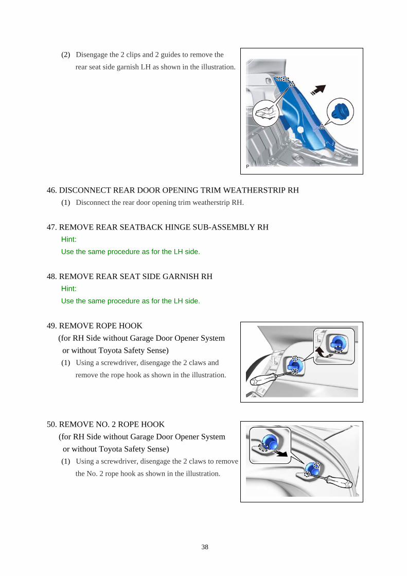
(2) Disengage the 2 clips and 2 guides to remove the
rear seat side garnish LH as shown in the illustration.
46. DISCONNECT REAR DOOR OPENING TRIM WEATHERSTRIP RH
(1) Disconnect the rear door opening trim weatherstrip RH.
47. REMOVE REAR SEATBACK HINGE SUB-ASSEMBLY RH
Hint:
Use the same procedure as for the LH side.
48. REMOVE REAR SEAT SIDE GARNISH RH
Hint:
Use the same procedure as for the LH side.
49. REMOVE ROPE HOOK
(for RH Side without Garage Door Opener System
or without Toyota Safety Sense)
(1) Using a screwdriver, disengage the 2 claws and
remove the rope hook as shown in the illustration.
50. REMOVE NO. 2 ROPE HOOK
(for RH Side without Garage Door Opener System
or without Toyota Safety Sense)
(1) Using a screwdriver, disengage the 2 claws to remove
the No. 2 rope hook as shown in the illustration.
39
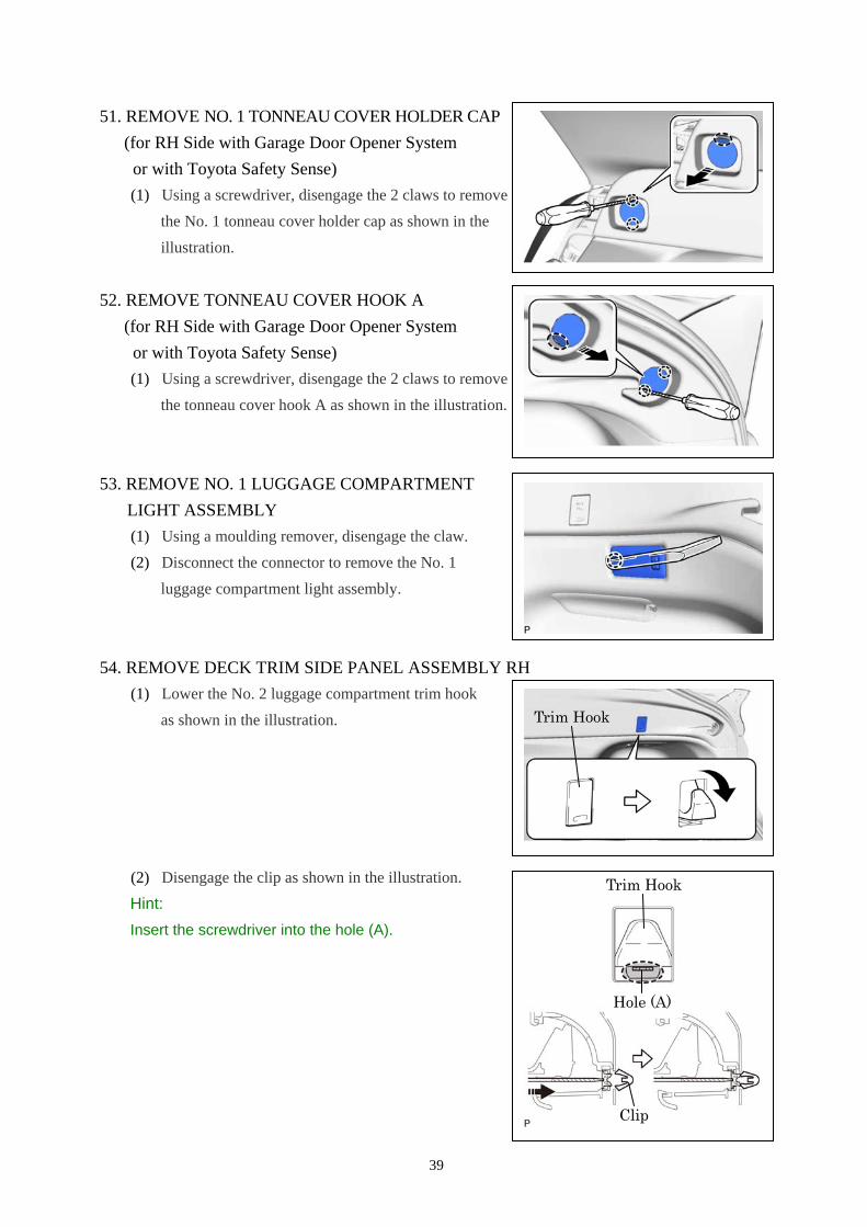
51. REMOVE NO. 1 TONNEAU COVER HOLDER CAP
(for RH Side with Garage Door Opener System
or with Toyota Safety Sense)
(1) Using a screwdriver, disengage the 2 claws to remove
the No. 1 tonneau cover holder cap as shown in the
illustration.
52. REMOVE TONNEAU COVER HOOK A
(for RH Side with Garage Door Opener System
or with Toyota Safety Sense)
(1) Using a screwdriver, disengage the 2 claws to remove
the tonneau cover hook A as shown in the illustration.
53. REMOVE NO. 1 LUGGAGE COMPARTMENT
LIGHT ASSEMBLY
(1) Using a moulding remover, disengage the claw.
(2) Disconnect the connector to remove the No. 1
luggage compartment light assembly.
54. REMOVE DECK TRIM SIDE PANEL ASSEMBLY RH
(1) Lower the No. 2 luggage compartment trim hook
as shown in the illustration.
(2) Disengage the clip as shown in the illustration.
Hint:
Insert the screwdriver into the hole (A).
Hole (A)
Trim Hook
Clip
Trim Hook
40
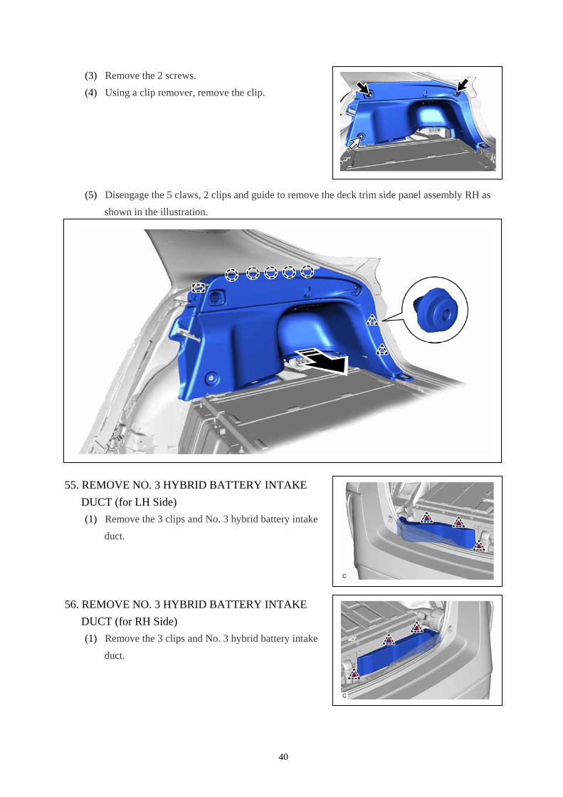
(3) Remove the 2 screws.
(4) Using a clip remover, remove the clip.
(5) Disengage the 5 claws, 2 clips and guide to remove the deck trim side panel assembly RH as
shown in the illustration.
55. REMOVE NO. 3 HYBRID BATTERY INTAKE
DUCT (for LH Side)
(1) Remove the 3 clips and No. 3 hybrid battery intake
duct.
56. REMOVE NO. 3 HYBRID BATTERY INTAKE
DUCT (for RH Side)
(1) Remove the 3 clips and No. 3 hybrid battery intake
duct.
41
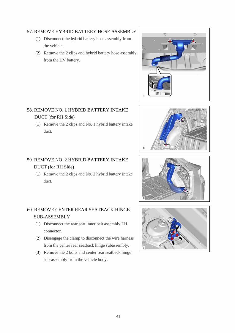
57. REMOVE HYBRID BATTERY HOSE ASSEMBLY
(1) Disconnect the hybrid battery hose assembly from
the vehicle.
(2) Remove the 2 clips and hybrid battery hose assembly
from the HV battery.
58. REMOVE NO. 1 HYBRID BATTERY INTAKE
DUCT (for RH Side)
(1) Remove the 2 clips and No. 1 hybrid battery intake
duct.
59. REMOVE NO. 2 HYBRID BATTERY INTAKE
DUCT (for RH Side)
(1) Remove the 2 clips and No. 2 hybrid battery intake
duct.
60. REMOVE CENTER REAR SEATBACK HINGE
SUB-ASSEMBLY
(1) Disconnect the rear seat inner belt assembly LH
connector.
(2) Disengage the clamp to disconnect the wire harness
from the center rear seatback hinge subassembly.
(3) Remove the 2 bolts and center rear seatback hinge
sub-assembly from the vehicle body.
42
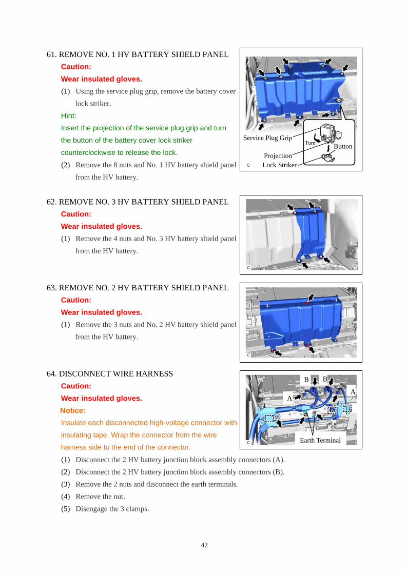
61. REMOVE NO. 1 HV BATTERY SHIELD PANEL
Caution:
Wear insulated gloves.
(1) Using the service plug grip, remove the battery cover
lock striker.
Hint:
Insert the projection of the service plug grip and turn
the button of the battery cover lock striker
counterclockwise to release the lock.
(2) Remove the 8 nuts and No. 1 HV battery shield panel
from the HV battery.
62. REMOVE NO. 3 HV BATTERY SHIELD PANEL
Caution:
Wear insulated gloves.
(1) Remove the 4 nuts and No. 3 HV battery shield panel
from the HV battery.
63. REMOVE NO. 2 HV BATTERY SHIELD PANEL
Caution:
Wear insulated gloves.
(1) Remove the 3 nuts and No. 2 HV battery shield panel
from the HV battery.
64. DISCONNECT WIRE HARNESS
Caution:
Wear insulated gloves.
Notice:
Insulate each disconnected high-voltage connector with
insulating tape. Wrap the connector from the wire
harness side to the end of the connector.
(1) Disconnect the 2 HV battery junction block assembly connectors (A).
(2) Disconnect the 2 HV battery junction block assembly connectors (B).
(3) Remove the 2 nuts and disconnect the earth terminals.
(4) Remove the nut.
(5) Disengage the 3 clamps.
Lock Striker
Turn Button
Projection
Service Plug Grip
Earth Terminal
A
B
A
B
43
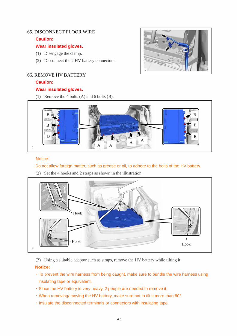
65. DISCONNECT FLOOR WIRE
Caution:
Wear insulated gloves.
(1) Disengage the clamp.
(2) Disconnect the 2 HV battery connectors.
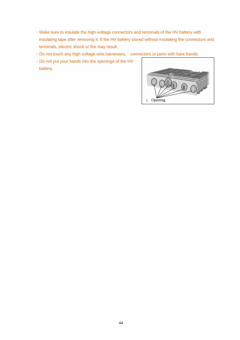
66. REMOVE HV BATTERY
Caution:
Wear insulated gloves.
(1) Remove the 4 bolts (A) and 6 bolts (B).
Notice:
Do not allow foreign matter, such as grease or oil, to adhere to the bolts of the HV battery.
(2) Set the 4 hooks and 2 straps as shown in the illustration.
(3) Using a suitable adaptor such as straps, remove the HV battery while tilting it.
Notice:
・To prevent the wire harness from being caught, make sure to bundle the wire harness using
insulating tape or equivalent.
・Since the HV battery is very heavy, 2 people are needed to remove it.
・When removing/ moving the HV battery, make sure not to tilt it more than 80°.
・Insulate the disconnected terminals or connectors with insulating tape.
A
B
B
B
A A A
B
B
B
Hook
Hook
Hook
44
・Make sure to insulate the high-voltage connectors and terminals of the HV battery with
insulating tape after removing it. If the HV battery stored without insulating the connectors and
terminals, electric shock or fire may result.
・Do not touch any high voltage wire harnesses, connectors or parts with bare hands.
・Do not put your hands into the openings of the HV
battery.
Opening