Printing - National Fire Codes 2006 Annual Revision...
141
Copyright NFPA N FPA 15 Standard for Water Spray Fixed Systems for Fire Protection 2007 Edition Copyright © 2006 National Fire Protection Association. All Rights Reserved. This edition of NFPA 15, Standard for Water Spray Fixed Systems for Fire Protection , was prepared by the Technical Committee on Water Spray Fixed Systems. It was issued by the Standards Council on July 28, 2006, with an effective date of August 17, 2006, a nd supersedes all previous editions. This edition of NFPA 15 was approved as an American National Standard on August 17, 2006. Origin and Development of NFPA 15 The Standard for Water Spray Fixed Systems for Fire Protection , formerly Water Spray Nozzles and Extinguishing Systems , first prepared by the Committee on Manufacturing Hazards, was tentatively adopted in 1939, with final adoption in 1940. Subsequently, th is standard was placed under the jurisdiction of the Committee on Special Extinguishing Systems, and a new edition was adopted in 1947. In 1959 the committee organization was further changed to place primary responsibility in the hands of the Committee on Water Spray, under the general supervision of the General Committee on Special Extinguishing Methods. In 1966 the General Committee on Special Extinguishing Methods was discontinued, and the Committee on Water Spray was constituted as an independent commit tee. Revised editions were presented in 1969, 1973, 1977, 1979, and 1982. The 1985 edition incorporated several technical changes concerning special piping provisions. The format of the document was also changed to more closely follow the NFPA Manual of Style . Given the limited changes in water spray technology over the past few years, it was apparent that the 1985 edition could be reconfirmed with referenced publications being updated. The 1996 edition represented a complete reorganization of the standard. Information was rearranged in a more functional and concise format to improve the
Transcript of Printing - National Fire Codes 2006 Annual Revision...
Copyright NFPA
NFPA 15Standard for
Water Spray Fixed Systems for Fire Protection
2007 Edition
Copyright © 2006 National Fire Protection Association. All Rights Reserved.
This edition of NFPA 15, Standard for Water Spray Fixed Systems for Fire Protection, was prepared by the Technical Committee on Water Spray FixedSystems. It was issued by the Standards Council on July 28, 2006, with an effective date of August 17, 2006, and supersedes all previous editions.
This edition of NFPA 15 was approved as an American National Standard on August 17, 2006.
Origin and Development of NFPA 15
The Standard for Water Spray Fixed Systems for Fire Protection, formerly Water Spray Nozzles and Extinguishing Systems, first prepared by the Committee onManufacturing Hazards, was tentatively adopted in 1939, with final adoption in 1940. Subsequently, this standard was placed under the jurisdiction of theCommittee on Special Extinguishing Systems, and a new edition was adopted in 1947. In 1959 the committee organization was further changed to place primaryresponsibility in the hands of the Committee on Water Spray, under the general supervision of the General Committee on Special Extinguishing Methods. In1966 the General Committee on Special Extinguishing Methods was discontinued, and the Committee on Water Spray was constituted as an independentcommittee. Revised editions were presented in 1969, 1973, 1977, 1979, and 1982.
The 1985 edition incorporated several technical changes concerning special piping provisions. The format of the document was also changed to more closelyfollow the NFPA Manual of Style.
Given the limited changes in water spray technology over the past few years, it was apparent that the 1985 edition could be reconfirmed with referencedpublications being updated.
The 1996 edition represented a complete reorganization of the standard. Information was rearranged in a more functional and concise format to improve the

Copyright NFPA
usability of the document.
Other major changes included a new chapter on high-speed systems, and revised requirements for spray nozzles, piping protection, spacing of pilot sprinklers,discharge densities, and design calculations.
The 2001 edition represented a complete reorganization of the standard to conform to the requirements of the 2000 edition of the Manual of Style for NFPATechnical Committee Documents.
The 2007 edition incorporates welding requirements for pipe and fittings as well as coordinating requirements for fire department connections with NFPA 13.
Technical Committee on Water Spray Fixed Systems
Kerry M. Bell, ChairUnderwriters Laboratories Inc., IL [RT]
Robert M. Gagnon, SecretaryGagnon Engineering, MD [SE]
Kevin F. Carrier, Miami-Dade County, FL [E]
Paul A. Cera, Schering-Plough Corporation, NJ [U]
Gary A. Fadorsen, Pyrotech International Inc., OH [IM]
Russell P. Fleming, National Fire Sprinkler Association, NY [IM]
Harvey E. Goranson, HSB Professional Loss Control, TN [I]
Scott D. Henderson, Fireman’s Fund Insurance Company, MA [I]
Stephen R. Hoover, Stephen R. Hoover Associates, IL [SE]
Thomas L. Jacquel, Allstate Fire Sprinkler Inc., CT [IM]Rep. American Fire Sprinkler Association
Robert A. Loyd, U.S. Department of the Army, IA [U]

Copyright NFPA
James M. Maddry, James M. Maddry, P.E., GA [SE]
Christy J. Marsolo, Tyco International Limited, GA [M]
David A. Moore, Jr., Ohio State Fire Marshals Office, OH [E]
Thomas L. Multer, Reliable Automatic Sprinkler Company, GA [M]Rep. National Fire Sprinkler Association
Larry W. Owen, Dooley Tackaberry, Inc., TX [IM]
Gerald F. Piasecki, Jr., U.S. National Aeronautics and Space Administration, OH [U]
Edward A. Ramirez, TVA Fire and Life Safety, Inc., MO [SE]
Lynn A. Rawls, GE Insurance Solutions, MS [I]
Rick R. Schartel, PPL Generation, LLC, PA [U]Rep. Edison Electric Institute
James D. Soden, Shell E&P Americas, TX [U]Rep. American Petroleum Institute
Frank J. Spitz, Jr., Spitz Fire Protection Design Company, MD [SE]
James R. Streit, U.S. Department of Energy, NM [U]
Dennis W. Taylor, Bechtel Corporation, TX [SE]
Alfred G. Vance, The Dow Chemical Company, TX [U]
Alternates
Michael J. Bosma, The Viking Corporation, MI [M](Alt. to T. L. Multer)

Copyright NFPA
George E. Laverick, Underwriters Laboratories Inc., IL [RT](Alt. to K. M. Bell)
Kenneth W. Linder, GE Insurance Solutions, CT [I](Alt. to L. A. Rawls)
David S. Mowrer, HSB Professional Loss Control, TN [I](Alt. to H. E. Goranson)
James R. Myers, S&S Sprinkler Company, LLC, AL [IM](Alt. to T. L. Jacquel)
Arkady Okun, ConEdison of New York, Inc., NY [U](Alt. to R. R. Schartel)
Robert V. Scholes, Fireman's Fund Insurance Company, CA [I](Alt. to S. D. Henderson)
Victoria B. Valentine, National Fire Sprinkler Association, NY [IM](Alt. to R. P. Fleming)
Terry L. Victor, Tyco/SimplexGrinnell, MD [M](Alt. to C. J. Marsolo)
David R. Hague, NFPA Staff Liaison
This list represents the membership at the time the Committee was balloted on the final text of this edition. Since that time, changes in the membership may have occurred. A keyto classifications is found at the back of the document.
NOTE: Membership on a committee shall not in and of itself constitute an endorsement of the Association or any document developed by the committee on which the memberserves.
Committee Scope: This Committee shall have primary responsibility for documents on the design, construction, installation, and test of fixed water spray systems for fireprotection purposes.
NFPA 15Standard for

Copyright NFPA
Water Spray Fixed Systems for Fire Protection2007 Edition
IMPORTANT NOTE: This NFPA document is made available for use subject to important notices and legal disclaimers. These notices and disclaimersappear in all publications containing this document and may be found under the heading “Important Notices and Disclaimers Concerning NFPADocuments.” They can also be obtained on request from NFPA or viewed at www.nfpa.org/disclaimers.
NOTICE: An asterisk (*) following the number or letter designating a paragraph indicates that explanatory material on the paragraph can be found in Annex A.
Changes other than editorial are indicated by a vertical rule beside the paragraph, table, or figure in which the change occurred. These rules are included as an aidto the user in identifying changes from the previous edition. Where one or more complete paragraphs have been deleted, the deletion is indicated by a bullet (•)between the paragraphs that remain.
A reference in brackets [ ] following a section or paragraph indicates material that has been extracted from another NFPA document. As an aid to the user, thecomplete title and edition of the source documents for extracts in mandatory sections of the document are given in Chapter 2 and those for extracts ininformational sections are given in Annex C. Editorial changes to extracted material consist of revising references to an appropriate division in this document orthe inclusion of the document number with the division number when the reference is to the original document. Requests for interpretations or revisions ofextracted text shall be sent to the technical committee responsible for the source document.
Information on referenced publications can be found in Chapter 2 and Annex C.
Chapter 1 Administration
1.1 Scope.
1.1.1 This standard provides the minimum requirements for the design, installation, and system acceptance testing of water spray fixed systems for fireprotection service and the minimum requirements for the periodic testing and maintenance of ultra high-speed water spray fixed systems.
1.1.2* Water spray fixed systems shall be specifically designed to provide for effective fire control, extinguishment, prevention, or exposure protection.
1.1.3* This standard shall not apply to water spray protection from portable nozzles, sprinkler systems, monitor nozzles, water mist suppression systems,explosion suppression, or other means of application covered by other standards of NFPA.
1.2 Purpose.
The purpose of this standard shall be to provide the minimum requirements for water spray fixed systems based upon sound engineering principles, test data, andfield experience.
Copyright NFPA
1.3 Application.
1.3.1 Water spray is applicable for protection of specific hazards and equipment and shall be permitted to be installed independently of, or supplementary to,other forms of fire protection systems or equipment.
1.3.2 Water spray protection is acceptable for the protection of hazards involving each of the following groups:
(1) Gaseous and liquid flammable materials
(2) Electrical hazards such as transformers, oil switches, motors, cable trays, and cable runs
(3) Ordinary combustibles such as paper, wood, and textiles
(4) Certain hazardous solids such as propellants and pyrotechnics
1.4 Retroactivity.
The provisions of this standard reflect a consensus of what is necessary to provide an acceptable degree of protection from the hazards addressed in this standardat the time the standard was issued.
1.4.1 Unless otherwise specified, the provisions of this standard shall not apply to facilities, equipment, structures, or installations that existed or were approvedfor construction or installation prior to the effective date of the standard. Where specified, the provisions of this standard shall be retroactive.
1.4.2 In those cases where the authority having jurisdiction determines that the existing situation presents an unacceptable degree of risk, the authority havingjurisdiction shall be permitted to apply retroactively any portions of this standard deemed appropriate.
1.4.3 The retroactive requirements of this standard shall be permitted to be modified if their application clearly would be impractical in the judgment of theauthority having jurisdiction, and only where it is clearly evident that a reasonable degree of safety is provided.
1.5 Equivalency.
Nothing in this standard is intended to prevent the use of systems, methods, or devices of equivalent or superior quality, strength, fire resistance, effectiveness,durability, and safety over those prescribed by this standard. Technical documentation shall be submitted to the authority having jurisdiction to demonstrateequivalency. The system, method, or device shall be approved for the intended purpose by the authority having jurisdiction.
1.6 Units and Formulas.
1.6.1 Metric units of measurement in this standard are in accordance with the modernized metric system known as the International System of Units (SI). Twounits (liter and bar), outside of but recognized by SI, are commonly used in international fire protection. These units are listed in Table 1.6.1, with conversionfactors.

Copyright NFPA
1.6.1 Metric units of measurement in this standard are in accordance with the modernized metric system known as the International System of Units (SI). Twounits (liter and bar), outside of but recognized by SI, are commonly used in international fire protection. These units are listed in Table 1.6.1, with conversionfactors.
Table 1.6.1 Unit Conversions
Name of Unit Unit Symbol Conversion FactorLiter L 1 gal = 3.785 LLiter per minute per square meter (L/min)/m2 1 gpm/ft2 = 40.746
(L/min)/m2
Cubic decimeter dm3 1 gal = 3.785 dm3
Pascal Pa 1 psi = 6894.757 PaBar bar 1 psi = 0.0689 barBar bar 1 bar = 105 Pa
Note: For additional conversions and information see IEEE/ASTM-SI-10, Standard Practice for Use of the International System of Units (SI): The Modern Metric System.

Copyright NFPA
1.6.2 If a value for measurement as given in this standard is followed by an equivalent value in another unit, the first stated shall be regarded as the requirement.A given equivalent value might be approximate.
1.6.3 The conversion procedure for the SI units has been to multiply the quantity by the conversion factor and then to round the result to the appropriate numberof significant digits.
Chapter 2 Referenced Publications
2.1 General.
The documents or portions thereof listed in this chapter are referenced within this standard and shall be considered part of the requirements of this document.
2.2 NFPA Publications.
National Fire Protection Association, 1 Batterymarch Park, Quincy, MA 02169-7471.
NFPA 13, Standard for the Installation of Sprinkler Systems, 2007 edition.
NFPA 20, Standard for the Installation of Stationary Pumps for Fire Protection, 2007 edition.
NFPA 22, Standard for Water Tanks for Private Fire Protection, 2003 edition.
NFPA 24, Standard for the Installation of Private Fire Service Mains and Their Appurtenances, 2007 edition.
NFPA 25, Standard for the Inspection, Testing, and Maintenance of Water-Based Fire Protection Systems, 2002 edition.
NFPA 51B, Standard for Fire Prevention During Welding, Cutting, and Other Hot Work, 2003 edition.
NFPA 70, National Electrical Code®, 2005 edition.
NFPA 72®, National Fire Alarm Code®, 2007 edition.
NFPA 1963, Standard for Fire Hose Connections, 2003 edition.
2.3 Other Publications.
2.3.1 ANSI Publications.
American National Standards Institute, Inc., 25 West 43rd Street, 4th Floor, New York, NY 10036.
Copyright NFPA
ANSI/ASME B1.20.1, Pipe Threads, General Purpose, 1983.
ANSI B16.1, Cast Iron Pipe Flanges and Flanged Fittings, 1998.
ANSI B16.3, Malleable Iron Threaded Fittings, 1998.
ANSI B16.4, Gray Iron Threaded Fittings, 1998.
ANSI B16.5, Pipe Flanges and Flanged Fittings, 2003.
ANSI B16.9, Factory-Made Wrought Steel Buttwelding Fittings, 2003.
ANSI B16.11, Forged Fittings, Socket-Welding and Threaded, 2001.
ANSI B16.18, Cast Copper Alloy Solder Joint Pressure Fittings, 2001.
ANSI B16.22, Wrought Copper and Copper Alloy Solder Joint Pressure Fittings, 2001.
ANSI B16.25, Buttwelding Ends, 1997.
ANSI B36.10M, Welded and Seamless Wrought Steel Pipe, 2000.
ANSI B36.19M, Stainless Steel Pipe, 1985.
ANSI C2, National Electrical Safety Code, 2002.
2.3.2 ASME Publication.
American Society of Mechanical Engineers, Three Park Avenue, New York, NY 10016-5990.
ASME Section IX, Welding and Brazing Qualifications, 2003.
2.3.3 ASTM Publications.
ASTM International, 100 Barr Harbor Drive, Box C700, West Conshohocken, PA 19428-2959.
ASTM A 53, Standard Specification for Pipe, Steel, Black and Hot-Dipped, Zinc-Coated, Welded and Seamless, 2004.
ASTM A 135, Standard Specification for Electric-Resistance-Welded Steel Pipe, 2001.
ASTM A 182, Standard Specification for Forged or Rolled Alloy-Steel Pipe Flanges, Forged Fittings, and Valves and Parts for High-Temperature Service,2004.
ASTM A 234, Standard Specification for Piping Fittings of Wrought Carbon Steel and Alloy Steel for Moderate and High Temperature Service, 2004.
ASTM A 312, Standard Specification for Seamless Welded and Heavily Cold Worked Austenitic Stainless Steel Pipes, 2004.

Copyright NFPA
ASTM A 536, Standard Specification for Ductile Iron Castings, 1984.
ASTM A 795, Standard Specification for Black and Hot-Dipped Zinc-Coated (Galvanized) Welded and Seamless Steel Pipe for Fire Protection Use, 2004.
ASTM B 75, Standard Specification for Seamless Copper Tube, 2002.
ASTM B 88, Standard Specification for Seamless Copper Water Tube, 2003.
ASTM B 251, Standard Specification for General Requirements for Wrought Seamless Copper and Copper-Alloy Tube, 2002.
2.3.4 AWS Publications.
American Welding Society, 550 N. W. LeJeune Road, Miami, FL 33126.
AWS A5.8, Specification for Filler Metals for Brazing and Braze Welding, 2004.
AWS B2.1, Specification for Welding Procedures and Performance Qualification, 2005.
AWS B2.2, Standard for Brazing Procedure and Performance Qualification, 1991.
2.3.5 IEEE Publication.
Institute of Electrical and Electronics Engineers, Three Park Avenue, 17th Floor, New York, NY 10016-5997.
IEEE/ASTM-SI-10, Standard Practice for Use of the International System of Units (SI): The Modern Metric System, 2002.
2.3.6 Other Publications.
Merriam-Webster’s Collegiate Dictionary, 11th edition, Merriam-Webster, Inc., Springfield, MA, 2003.
2.4 References for Extracts in Mandatory Sections.
NFPA 13, Standard for the Installation of Sprinkler Systems, 2007 edition.
NFPA 25, Standard for the Inspection, Testing, and Maintenance of Water-Based Fire Protection Systems, 2002 edition.
Chapter 3 Definitions
3.1 General.
The definitions contained in this chapter shall apply to the terms used in this standard. Where terms are not defined in this chapter or within another chapter, theyshall be defined using their ordinarily accepted meanings within the context in which they are used. Merriam-Webster’s Collegiate Dictionary, 11th edition, shall

Copyright NFPA
be the source for the ordinarily accepted meaning.
3.2 NFPA Official Definitions.
3.2.1* Approved. Acceptable to the authority having jurisdiction.
3.2.2* Authority Having Jurisdiction (AHJ). An organization, office, or individual responsible for enforcing the requirements of a code or standard, or forapproving equipment, materials, an installation, or a procedure.
3.2.3* Listed. Equipment, materials, or services included in a list published by an organization that is acceptable to the authority having jurisdiction andconcerned with evaluation of products or services, that maintains periodic inspection of production of listed equipment or materials or periodic evaluation ofservices, and whose listing states that either the equipment, material, or service meets appropriate designated standards or has been tested and found suitable fora specified purpose.
3.2.4 Shall. Indicates a mandatory requirement.
3.2.5 Should. Indicates a recommendation or that which is advised but not required.
3.3 General Definitions.
3.3.1 Combined System. A system of piping that connects both sprinklers and water spray nozzles in a common fire area, and is supplied by a single riser andsystem actuation valve.
3.3.2 Control of Burning. Application of water spray to equipment or areas where a fire can occur to control the rate of burning and thereby limit the heatrelease from a fire until the fuel can be eliminated or extinguishment effected.
3.3.3 Deflagration. Propagation of a combustion zone at a velocity that is less than the speed of sound in the unreacted medium.
3.3.4 Density. The unit rate of water application to an area or surface expressed in gpm/ft2 [(L/min)/m2].
3.3.5 Detection Equipment.
3.3.5.1 Automatic Detection Equipment. Equipment that automatically detects heat, flame, products of combustion, flammable gases, or other conditions likelyto produce fire or explosion and cause other automatic actuation of alarm and protection equipment. [25, 2002]
3.3.5.2 Flammable Gas Detection Equipment. Equipment that will automatically detect a percent volume concentration of a flammable gas or vapor relative toa predetermined level.
3.3.6 Detonation. Propagation of a combustion zone at a velocity that is greater than the speed of sound in the unreacted medium.
3.3.7 Electrical Clearance. The air distance between the water spray equipment, including piping and nozzles, and unenclosed or uninsulated live electricalcomponents at other than ground potential.
Copyright NFPA
3.3.8 Exposure Protection. Absorption of heat through application of water spray to structures or equipment exposed to a fire, to limit surface temperature to alevel that will minimize damage and prevent failure.
3.3.9* Fire Area. An area that is physically separated from other areas by space, barriers, walls, or other means in order to contain fire within that area.
3.3.10 Flammable and Combustible Liquids. Flammable liquids shall be or shall include any liquids having a flash point below 100°F (37.8°C) and having avapor pressure not exceeding 40 psi (276 kPa) (absolute) at 100°F (37.8°C). Flammable liquids shall be subdivided as follows: Class I liquids shall include thosehaving flash points below 100°F (37.8°C) and shall be subdivided as follows: (1) Class IA liquids shall include those having flash points below 73°F (22.8°C)and having a boiling point below 100°F (37.8°C); (2) Class IB liquids shall include those having flash points below 73°F (22.8°C) and having a boiling pointabove 100°F (37.8°C); (3) Class IC liquids shall include those having flash points at or above 73°F (22.8°C) and below 100°F (37.8°C). Combustible liquidsshall be or shall include any liquids having a flash point at or above 100°F (37.8°C). They shall be subdivided as follows: (1) Class II liquids shall include thosehaving flash points at or above 100°F (37.8°C) and below 140°F (60°C); (2) Class IIIA liquids shall include those having flash points at or above 140°F (60°C)and below 200°F (93.3°C); (3) Class IIIB liquids shall include those having flash points at or above 200°F (93.3°C).
3.3.11 Impingement. The striking of a protected surface by water droplets issuing directly from a water spray nozzle.
3.3.12 Insulation.
3.3.12.1* Insulated. Refers to equipment, structures, or vessels provided with an encapsulating material that, for the expected duration of fire exposure, willlimit steel temperatures to a maximum of 850°F (454°C) for structural members or 650°F (343°C) for vessels. The insulation system shall be: (1)Noncombustible and fire retardant; (2) Mildew and weather resistant; (3) Resistant to the force of hose streams; and (4) Secured by fire and corrosion-resistantfastenings.
3.3.12.2 Uninsulated. Refers to equipment, structures, or vessels not provided with an encapsulating material that meets the requirements defined as “insulated.”
3.3.13 Net Rate. The total rate of water discharge density, less water wastage due to factors such as wind effects and inaccuracies in nozzle angles of spray.
3.3.14* Nonabsorbing Ground. Earth or fill that is not readily permeable or absorbent to large quantities of flammable or combustible liquid or water, or both.
3.3.15 Pilot Sprinkler. An automatic sprinkler or thermostatic fixed temperature release device used as a detector to pneumatically or hydraulically release thesystem actuation valve.
3.3.16 Rundown. The downward travel of water along a surface, caused by the momentum of the water or by gravity.
3.3.17 Ultra High-Speed Water Spray System. A type of automatic water spray system where water spray is rapidly applied to protect specific hazards wheredeflagrations are anticipated.
3.3.17.1 Ultra High-Speed Water Spray System — Area Application. The application of ultra high-speed water spray over a specific floor area or over thesurface area of a specific object.
3.3.17.2 Ultra High-Speed Water Spray System — Local Application. The application of ultra high-speed water spray on a specific point or points of

Copyright NFPA
ignition, such as cutting, mixing or grinding operations.
3.3.18 Valve.
3.3.18.1 Deluge Valve. A type of system actuation valve that is opened by the operation of a detection system installed in the same areas as the spray nozzles orby remote manual operation supplying water to all spray nozzles.
3.3.18.2 System Actuation Valve. The main valve that controls the flow of water into the water spray system.
3.3.19 Water Spray. Water in a form having a predetermined pattern, particle size, velocity, and density discharge from specially designed nozzles or devices.
3.3.20 Water Spray Nozzle.
3.3.20.1 Automatic Water Spray Nozzle. A nozzle intended to open automatically by operation of a heat responsive element that maintains the dischargeorifice closed by means such as the exertion of force on a cap (button or disc), that when discharging water under pressure, will distribute the water in a specific,directional pattern.
3.3.20.2* Open Water Spray Nozzle. An open water discharge device that, when discharging water under pressure, will distribute the water in a specific,directional pattern.
3.3.21* Water Spray System. An automatic or manually actuated fixed pipe system connected to a water supply and equipped with water spray nozzlesdesigned to provide a specific water discharge and distribution over the protected surfaces or area.
3.3.22* Water Wastage. That discharge from water spray nozzles that does not impinge on the surface being protected.
Chapter 4 General Requirements
4.1* Design Objectives.
In general, water spray shall be considered effective for any one of or a combination of the following objectives (see Chapter 7):
(1) Extinguishment of fire
(2) Control of burning
(3) Exposure protection
(4) Prevention of fire
4.2 Special Considerations.
4.2.1 A study shall be made of the physical and chemical properties of the materials for which the water spray protection is being considered to determine the

Copyright NFPA
advisability of its use.
4.2.2 The flash point, specific gravity, viscosity, miscibility, and solubility and permeability of the material, temperature of the water spray, and the normaltemperature of the hazard to be protected are among the factors that shall be given consideration.
4.2.3* Where water spray can encounter confined materials at a high temperature or with a wide distillation range, the slopover or frothing hazard shall beevaluated.
4.2.4 Water Soluble Materials.
4.2.4.1 Where protecting water soluble materials, such as alcohol, systems shall be permitted to be designed for extinguishment by control, extinguishment bydilution, or extinguishment by an adequate application rate and coverage.
4.2.4.2 Each water soluble material shall be tested under the conditions of use to determine the applicability of a water spray system, unless design supportivedata is available.
4.2.5* Water spray shall not be used for direct application to materials that react with water, such as metallic sodium or calcium carbide, which produce violentreactions or increase hazardous products as a result of heated vapor emission.
4.2.6 Water spray shall not be used for applications involving liquefied gases at cryogenic temperatures (such as liquefied natural gas), which boil violentlywhen heated by water.
4.2.7 An evaluation shall be conducted, given the possibility of damage, distortion, or failure of equipment operating at high temperatures due to water sprayapplication.
4.3* Workmanship.
Water spray system design, layout, and installation shall be entrusted to fully experienced and responsible parties only.
4.4 Control of Runoff.
4.4.1* Water discharge from water spray systems shall be controlled or contained to prevent the spread of fire where flammable or combustible liquids arepresent.
4.4.2 Where flammable or combustible liquids are not present and the potential for water damage to adjacent areas is minimal, water discharged from waterspray systems shall not be required to be controlled or contained.
4.4.3* The control or containment system shall utilize any one of the following:
(1) Curbing and grading
(2) Underground or enclosed drains

Copyright NFPA
(3) Open trenches or ditches
(4) Diking or impoundment
(5) Any combination of 4.4.3(1) through (4)
4.4.4* Where the protected hazard involves the possible release of flammable or combustible liquids, the drainage system shall be designed to safely handleburning liquids.
4.4.5 Enclosed drain systems shall be fitted with traps or other means to prevent the entrance of flames or burning liquids into the system.
4.4.6 Open trenches and ditches shall be routed so as not to expose fire fighters, critical equipment and piping, other important structures, or property of others.
4.4.7 The control or containment system shall be designed to accommodate the total combined flow from all of the following:
(1)* All water spray systems intended to operate simultaneously within the fire area (where the actual discharge will exceed the design flow rate, the actualflow rate shall be used)
(2) Supplemental hose streams and monitor nozzle devices likely to be used during the fire
(3) The largest anticipated spill or accidental release of process liquids where applicable
(4) Any normal discharge of process liquids or cooling water into the drainage system
(5)* Rain water, provided local conditions warrant inclusion
4.4.8* The control or containment system shall be designed to accommodate the total combined flow for the fire’s expected duration.
4.4.9 Where approved, the system shall be permitted to be designed to accommodate the total combined flow for a period less than the fire’s expected duration.
4.4.10 The water and liquids drained from protected areas shall be collected and treated as required by local regulations.
4.4.11 Hazardous chemicals and contaminated water shall not be discharged to open waterways or onto the property of others.
Chapter 5 System Components
5.1 General.
5.1.1 All component parts shall be coordinated to provide complete systems.
5.1.2 Only listed materials and devices shall be used in the installation of water spray systems.

Copyright NFPA
5.1.2.1 Components that do not affect system operation, such as drain valves and signs, shall not be required to be listed.
5.1.2.2 Only new materials and devices shall be employed in the installation of new water spray systems.
5.1.2.3 The use of reconditioned valves and devices, other than automatic water spray nozzles, as replacement equipment in existing systems shall be permitted.
5.1.3 System components shall be rated for the maximum working pressure to which they are exposed, but not less than 175 psi (12.1 bar).
5.1.4 System components installed outside, or in the presence of a corrosive atmosphere, shall be constructed of materials that will resist corrosion or be suitablyprotected from corrosion.
5.2 Water Spray Nozzles.
Water spray nozzles shall be of a type listed for use in water spray systems with the following discharge characteristics:
(1) K factor
(2) Spray patterns at various pressures, distances, and orientation angles
(3) Uniformity of water distribution over its spray pattern
5.2.1 Water spray nozzles shall be permanently marked with their characteristics according to their listing.
5.2.2 Standard temperature ratings and color code designations of automatic water spray nozzles shall be as required for automatic sprinklers in NFPA 13,Standard for the Installation of Sprinkler Systems.
5.2.3 Special Coatings.
5.2.3.1 Listed corrosion-resistant spray nozzles shall be installed in locations where chemicals, moisture, or other corrosive vapors sufficient to cause corrosionof such devices exist.
5.2.3.2 Corrosion-Resistant Coatings.
5.2.3.2.1 Corrosion-resistant coatings shall be applied by the manufacturer of the spray nozzle.
5.2.3.2.2 Any damage to the protective coating occurring at the time of installation shall be repaired immediately, using only the coating of the manufacturer ofthe spray nozzle in the approved manner so that no part of the spray nozzle will be exposed after installation.
5.2.3.3* Painting.
5.2.3.3.1 Unless applied by the manufacturer, spray nozzles shall not be painted.
5.2.3.3.2 Any spray nozzles that have been painted by other than the manufacturer or after installation shall be replaced with spray nozzles of the samecharacteristics, including K factor, thermal response (automatic nozzles), and water distribution.

Copyright NFPA
5.2.4 Guards. Automatic water spray nozzles subject to mechanical damage shall be protected with listed guards.
5.2.5* Stock of Spare Automatic Water Spray Nozzles and Pilot Sprinklers.
5.2.5.1 A supply of automatic water spray nozzles and pilot sprinklers shall be maintained on the premises so that any automatic water spray nozzles or pilotsprinklers that have operated or been damaged in any way can be promptly replaced.
5.2.5.2 These automatic water spray nozzles and pilot sprinklers shall correspond to the types and temperature ratings of the automatic water spray nozzles andpilot sprinklers on the property.
5.2.5.3 The automatic water spray nozzles and pilot sprinklers shall be kept in a cabinet where the ambient storage temperature does not exceed 100°F (38°C).
5.2.5.4 Where required by the manufacturer, a special automatic water spray nozzle and/or pilot sprinkler wrench shall be provided to be used in the removaland installation of automatic water spray nozzles and pilot sprinklers.
5.2.5.5 The stock of spare automatic water spray nozzles and pilot sprinklers shall include as a minimum 1 of each type of automatic water spray nozzle andpilot sprinkler present on the property and shall in no case be less than the following total quantities based on the total number of automatic water spray nozzlesand pilot sprinklers on the property:
(1) For properties with less than 300 automatic water spray nozzles or pilot sprinklers, not less than 6 automatic water spray nozzles or pilot sprinklers
(2) For properties with 300 to 1000 automatic water spray nozzles or pilot sprinklers, not less than 12 automatic water spray nozzles or pilot sprinklers
(3) For properties with over 1000 automatic water spray nozzles or pilot sprinklers, not less than 24 automatic water spray nozzles or pilot sprinklers
5.3 Pipe and Tube.
5.3.1 Pipe or tube used in water spray systems shall meet or exceed one of the standards in Table 5.3.1 or be in accordance with 5.3.4. In addition, steel pipeshall be in accordance with 5.3.2 and 5.3.3, and copper tube shall be in accordance with 5.3.4.
Table 5.3.1 Pipe or Tube Specifications
Materials and Dimensions StandardFerrous Piping (Welded and Seamless)Stainless Steel Pipe ANSI B36.19MStandard Specification for Seamless and Welded Austenitic Stainless Steel Pipes ASTM A 312Standard Specification for Black and Hot-Dipped Zinc-Coated (Galvanized) Welded and Seamless Steel Pipe for Fire ProtectionUse*
ASTM A 795
Standard Specification for Pipe, Steel, Black and Hot-Dipped, Zinc-Coated, Welded and Seamless* ASTM A 53Welded and Seamless Wrought Steel Pipe ANSI B36.10MStandard Specification for Electric-Resistance-Welded Steel Pipe ASTM A 135

Copyright NFPA
Table 5.3.1 Pipe or Tube Specifications
Materials and Dimensions StandardCopper Tube (Drawn, Seamless)Standard Specification for Seamless Copper Tube* ASTM B 75Standard Specification for Seamless Copper Water Tube* ASTM B 88Standard Specification for General Requirements for Wrought Seamless Copper and Copper-Alloy Tube ASTM B 251Specification for Filler Metals for Brazing and Braze Welding (Classification BCuP-3 or BCuP-4) AWS A5.8
*Denotes pipe or tubing suitable for bending according to ASTM standards.
5.3.2* Where steel pipe listed in Table 5.3.1 is used and joined by welding or by roll grooved pipe and fittings, the minimum nominal wall thickness forpressures up to 300 psi (20.7 bar) shall be in accordance with Schedule 10 for pipe sizes up to 5 in. (127 mm); 0.134 in. (3.40 mm) for 6 in. (152 mm ) pipe; and0.188 in. (4.78 mm) for 8 in. and 10 in. (203 mm and 254 mm) pipe.
5.3.2.1 Pressure limitations and wall thickness for steel pipe listed in accordance with 5.3.5 shall be in accordance with the listing requirements.
5.3.3 Where steel pipe listed in Table 5.3.1 is joined by threaded fittings or by fittings used with pipe having cut grooves, the minimum wall thickness shall be inaccordance with Schedule 30 [in pipe sizes 8 in. (203 mm) and larger] or Schedule 40 [in pipe sizes less than 8 in. (203 mm)] for pressures up to 300 psi (20.7bar).
5.3.4 Copper tube shall be permitted in water-filled water spray systems where system pressures do not exceed 175 psi (12.1 bar). Copper tube specified in thestandards listed in Table 5.3.1 shall have wall thicknesses of Type K, L, or M.
5.3.5* Other types of pipe or tube investigated for suitability in automatic water spray installations and listed for this service, including but not limited to steeldiffering from that provided in Table 5.3.1, shall be permitted where installed in accordance with their listing limitations, including installation instructions.Bending of pipe shall be permitted as allowed by the listing.
5.3.6 Steel Piping.
5.3.6.1 Steel pipe used in manual and open systems shall be galvanized on its internal and external surfaces in accordance with Table 5.3.1.
5.3.6.2 The threaded ends of galvanized pipe shall be protected against corrosion.
5.3.6.3 Water-filled steel piping shall be permitted to be black steel.
5.3.6.4 Stainless steel pipe shall not be required to be galvanized.
5.3.7 Corrosion Protection. Where no other piping material will provide the required corrosion resistance for a particular corrosive application, listed coatedpipe or an approved corrosion resistance system applied to piping shall be permitted.
Copyright NFPA
5.3.8 Minimum Pipe Size. The minimum pipe size shall be 1 in. (25 mm) for steel and galvanized steel, and ¾ in. (19 mm) for copper and stainless steel.
5.3.9 Pipe Bending.
5.3.9.1 Bending of steel piping of wall thickness equal to or greater than Schedule 10 and Types K and L copper tube shall be permitted where bends are madewith no kinks, ripples, distortions, reductions in internal diameter, or any noticeable deviations from round.
5.3.9.2 For Schedule 40 steel piping and Types K and L copper tubing, the minimum radius of bend shall be 6 pipe diameters for pipe sizes 2 in. (51 mm) andsmaller, and 5 pipe diameters for pipe sizes 2½ in. (64 mm) and larger.
5.3.9.3 For all other types of steel pipe, the minimum radius of bend shall be 12 pipe diameters for all pipe sizes.
5.3.10 Pipe Identification.
5.3.10.1 All pipe, including specially listed pipe allowed by 5.3.5, shall be marked continuously along its length by the manufacturer in such a way as toproperly identify the type of pipe.
5.3.10.2 This identification shall include the manufacturer’s name, model designation, or schedule.
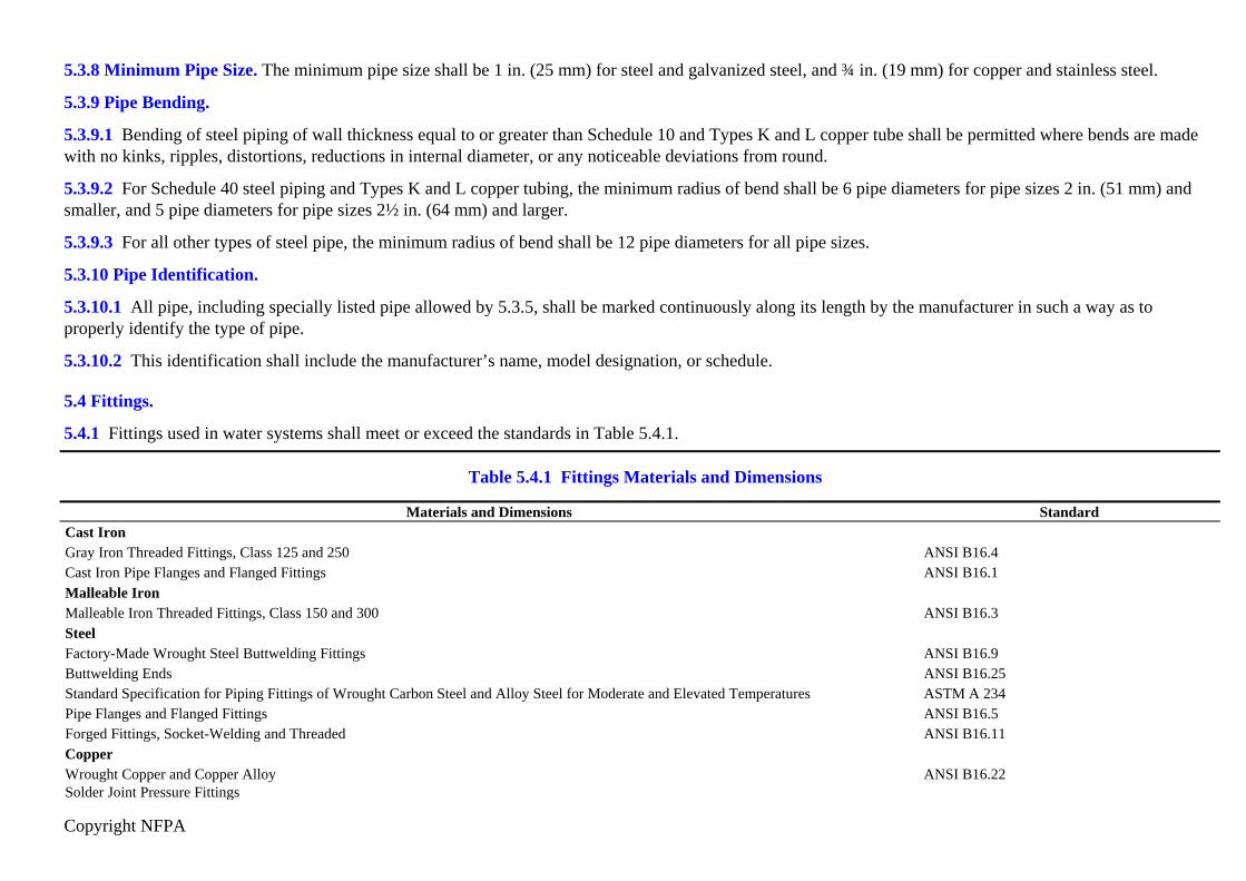
5.4 Fittings.
5.4.1 Fittings used in water systems shall meet or exceed the standards in Table 5.4.1.
Table 5.4.1 Fittings Materials and Dimensions
Materials and Dimensions StandardCast IronGray Iron Threaded Fittings, Class 125 and 250 ANSI B16.4Cast Iron Pipe Flanges and Flanged Fittings ANSI B16.1Malleable Iron Malleable Iron Threaded Fittings, Class 150 and 300 ANSI B16.3SteelFactory-Made Wrought Steel Buttwelding Fittings ANSI B16.9Buttwelding Ends ANSI B16.25Standard Specification for Piping Fittings of Wrought Carbon Steel and Alloy Steel for Moderate and Elevated Temperatures ASTM A 234Pipe Flanges and Flanged Fittings ANSI B16.5Forged Fittings, Socket-Welding and Threaded ANSI B16.11CopperWrought Copper and Copper Alloy Solder Joint Pressure Fittings
ANSI B16.22

Copyright NFPA
Table 5.4.1 Fittings Materials and Dimensions
Materials and Dimensions StandardCast Copper Alloy Solder Joint Pressure Fittings ANSI B16.18Ductile IronStandard Specification for Ductile Iron Castings ASTM A 536Stainless SteelStandard Specification for Forged or Rolled Alloy-Steel Pipe Flanges, Forged Fittings, and Valves and Parts for High-Temperature Service ASTM A 182
5.4.2 In dry sections of the piping exposed to possible fire or in self-supporting systems, ferrous fittings shall be of steel, malleable iron, or ductile iron.
5.4.3 Galvanized fittings shall be used where galvanized pipe is used.
5.4.4 Other types of fittings investigated for suitability in water spray system installations and listed for this service, including but not limited to fiberglass andsteel differing from that provided in Table 5.4.1, shall be permitted when installed in accordance with their listing limitations, including installation instructions.
5.4.5 Fittings shall be extra heavy pattern where pressures exceed 175 psi (12 bar).
5.4.6 Standard weight pattern malleable iron fittings 6 in. (150 mm) in size or smaller shall be permitted where pressures do not exceed 300 psi (20.7 bar).
5.4.7 Listed fittings shall be permitted for system pressures up to the limits specified in their listings.
5.4.8 Couplings and Unions.
5.4.8.1 Screwed unions shall not be used on pipe larger than 2 in. (50 mm).
5.4.8.2 Couplings and unions of other than screwed type shall be of types listed specifically for use in water spray or sprinkler systems.
5.4.9 Reducers and Bushings.
5.4.9.1 A one-piece reducing fitting shall be used wherever a change is made in the size of pipe.
5.4.9.2 Hexagonal or face bushings shall be permitted for use in reducing the size of openings of fittings where standard fittings of the required size and materialare not available from the manufacturer.
5.4.10* Rubber-gasketed fittings shall be permitted to be used to connect pipe in fire-exposed areas where the water spray system is automatically controlled.
5.4.11 Fire-exposed areas where rubber-gasketed fittings are located shall be protected by automatic water spray systems or other approved means.
5.5 Joining of Pipe and Fittings.
Copyright NFPA
5.5.1 Threaded Pipe and Fittings.
5.5.1.1 All threaded pipe and fittings shall have threads cut in accordance with ANSI/ASME B1.20.1, Pipe Threads, General Purpose.
5.5.1.2* Steel pipe with wall thicknesses less than Schedule 30 [in pipe sizes 8 in. (200 mm) and larger] or Schedule 40 [in pipe sizes less than 8 in. (200 mm)]shall not be joined by threaded fittings.
5.5.1.3 Where wall thicknesses are less than those required in 5.5.1.2, pipes shall be permitted to be threaded where the threaded assembly is investigated andlisted for this service.
5.5.1.4 Joint compound or tape shall be applied only to male threads.
5.5.2* Welded Pipe and Fittings.
5.5.2.1 General. Welding shall be permitted as a means of joining water spray system piping in accordance with 5.5.2.2 through 5.5.2.6.
5.5.2.2 Fabrication.
5.5.2.2.1 Field welding shall be permitted provided that the requirements of 5.5.2 through 5.5.2.5 are met.
5.5.2.2.2 When welding in the field, safe welding and cutting practices shall be followed in accordance with NFPA 51B, Standard for Fire Prevention DuringWelding, Cutting, and Other Hot Work.
5.5.2.2.3 Welding shall not be performed where there is impingement of rain, snow, sleet, or high wind on the weld area of the pipe product.
5.5.2.2.4 Torch cutting and welding shall not be permitted as a means of modifying or repairing water spray systems.
5.5.2.2.5 Where longitudinal earthquake braces are provided, tabs welded to pipe for longitudinal earthquake braces shall be permitted.
5.5.2.2.6 Where welded piping is to be galvanized, pipe shall be fabricated into spooled sections and shall be galvanized after fabrication.
5.5.2.3 Fittings.
5.5.2.3.1 Welded fittings used to join pipe shall be listed fabricated fittings or manufactured in accordance with Table 5.4.1.
5.5.2.3.2 Manufactured fittings joined in conformance with a qualified welding procedure as set forth in this section shall be permitted to be an acceptableproduct under this standard, provided that materials and wall thickness are compatible with other sections of this standard.
5.5.2.3.3 Fittings shall not be required where pipe ends are butt-welded in accordance with the requirements of 5.5.2.4.3.
5.5.2.3.4 When reducing the pipe size in a run of piping, a reducing fitting designed for that purpose shall be used.
5.5.2.4 Welding Requirements.

Copyright NFPA
5.5.2.4.1* Welds between pipe and welding outlet fittings shall be permitted to be attached by full penetration, partial penetration, or fillet welds.
5.5.2.4.2* The minimum throat thickness shall be not less than the thickness of the pipe, the thickness of the welding fitting, or in. (5 mm), whichever isleast.
5.5.2.4.3* Circumferential butt joints shall be cut, beveled, and fit so that full penetration is achievable. Full penetration welding shall not be required.
5.5.2.4.4 Where slip-on flanges are welded to pipe with a single fillet weld, the weld shall be on the hub side of the flange, and the minimum throat weldthickness shall not be less than 1.25 times the pipe wall thickness or the hub thickness, whichever is less.
5.5.2.4.5 Face welds on the internal face of the flange shall be permitted as a water seal in addition to the hub weld required in 5.5.2.4.4.
5.5.2.4.6 Tabs for longitudinal earthquake bracing shall have minimum throat weld thickness not less than 1.25 times the pipe wall thickness and welded on bothsides of the longest dimension.
5.5.2.4.7 Where welding is performed, the following shall apply:
(1) Holes cut in piping for outlets shall be cut to the full inside diameter of fittings prior to welding in place of the fittings.
(2) Discs shall be retrieved.
(3) Openings cut into piping shall be smooth bore, and all internal slag and welding residue shall be removed.
(4) Fittings shall not penetrate the internal diameter of the piping.
(5) Steel plates shall not be welded to the ends of piping or fitting.
(6) Fittings shall not be modified.
(7) Nuts, clips, eye rods, angle brackets, or other fasteners shall not be welded to pipe or fittings, except as permitted in 5.5.2.2.5 and 5.5.2.4.6.
(8) Completed welds shall be free from cracks, incomplete fusion, surface porosity greater than in. (1.5 mm) diameter, and undercut deeper than 25percent of the wall thickness or in., (0.8 mm).
(9) Completed circumferential butt weld reinforcements shall not exceed in. (2.4 mm).
5.5.2.5 Qualifications.
5.5.2.5.1 A welding procedure shall be prepared and qualified by the contractor or fabricator before any welding is done.
5.5.2.5.2 Qualification of the welding procedure to be used and the performance of all welders and welding operators shall be required and shall meet or exceed

Copyright NFPA
the requirements of American Welding Society Standard AWS B2.1, Specification for Welding Procedures and Performance Qualification; ASME Section IX,Welding and Brazing Qualifications; or other applicable qualification standard as required by the AHJ, except as permitted by 5.5.2.5.4.
5.5.2.5.3 Successful procedure qualification of complete joint penetration groove welds shall qualify partial joint penetration (groove/fillet) welds and filletwelds in accordance with the provisions of this standard.
5.5.2.5.4 Welding procedures qualified under standards recognized by previous editions of this standard shall be permitted to be continued in use.
5.5.2.5.5 Contractors or fabricators shall be responsible for all welding they produce.
5.5.2.5.6 Each contractor or fabricator shall have available to the authority having jurisdiction an established written quality assurance procedure ensuringcompliance with the requirements of 5.5.2.5.
5.5.2.6 Records.
5.5.2.6.1 Welders or welding machine operators shall, upon completion of each welded pipe, place their identifiable mark or label onto each piece adjacent to aweld.
5.5.2.6.2 Contractors or fabricators shall maintain certified records of the procedures used and the welders or welding machine operators employed by them,along with their welding identification, which shall be available to the authority having jurisdiction.
5.5.2.6.3 Records shall show the date and the results of procedure and performance qualifications and shall be available to the authority having jurisdiction.
5.5.3 Groove Joining Methods.
5.5.3.1 Pipe joined with grooved fittings shall be joined by a listed combination of fittings, gaskets, and grooves.
5.5.3.2 Grooves cut or rolled on pipe shall be dimensionally compatible with the fittings.
5.5.4* Brazed Joints.
5.5.4.1* Joints for the connection of copper tube shall be brazed using the brazing material in Table 5.3.1.
5.5.4.2 Field brazing shall be permitted.
5.5.4.3 Safe brazing practices shall be followed in accordance with NFPA 51B, Standard for Fire Prevention During Welding, Cutting, and Other Hot Work.
5.5.4.4 Brazing methods shall comply with all of the requirements of AWS B2.2, Standard for Brazing Procedure and Performance Qualification.
5.5.4.5 Fittings used to join copper tube shall be manufactured in accordance with Table 5.4.1 or shall be listed mechanically formed/extruded connectionsystems.
5.5.4.6 No brazing shall be performed if there is impingement of rain, snow, sleet, or high wind on the braze area of the tube product.

Copyright NFPA
5.5.4.7 Brazing shall be performed in accordance with the following:
(1) Fittings and branch connections shall not penetrate the internal diameter of the tubing.
(2) Copper plates shall not be brazed to the ends of tubing or fittings.
(3) Fittings shall not be modified.
(4) Nuts, clips, eye rods, angle brackets, or other fasteners shall not be brazed to tube or fittings.
5.5.4.8 Where the tube size in a run of tubing is being reduced, a reducing fitting designed for that purpose shall be used.
5.5.4.9 Qualifications.
5.5.4.9.1 A brazing procedure shall be prepared and qualified by the contractor or fabricator before any brazing is done.
5.5.4.9.2 Qualification of the brazing procedure to be used and performance of all brazers and brazing operators shall be required and shall meet or exceed therequirements of AWS B2.2, Standard for Brazing Procedure and Performance Qualification.
5.5.4.9.3 Contractors or fabricators shall be responsible for all brazing they produce.
5.5.4.9.4 Each contractor or fabricator shall have available to the authority having jurisdiction an established written quality assurance procedure ensuringcompliance with the requirements of 5.5.4.7.
5.5.4.9.5 Records.
5.5.4.9.5.1 Contractors and fabricators shall maintain certified records of the brazing procedures used and the brazers and brazing operators employed by them.
5.5.4.9.5.2 Records shall show the date and the results of procedure and performance qualification, and shall be available to the authority having jurisdiction.
5.5.5 Other Types. Other joining methods investigated for suitability in water spray sprinkler installations and listed for this service shall be permitted whereinstalled in accordance with their listing limitations, including installation instructions.
5.5.6 End Treatment.
5.5.6.1 Pipe ends shall have burrs and fins removed after cutting.
5.5.6.2 Pipe used with listed fittings and its end treatment shall be in accordance with the fitting manufacturer’s installation instructions and the fitting’s listing.
5.6 Hangers.
5.6.1 General. The types of hangers used shall be in accordance with the requirements of NFPA 13, Standard for the Installation of Sprinkler Systems.
5.6.2 Hangers used outdoors or in locations where corrosive conditions exist shall be galvanized, suitably coated, or fabricated from corrosion-resistive

Copyright NFPA
materials.
5.7 Valves.
5.7.1 Control Valves.
5.7.1.1 All valves controlling connections to water supplies and to supply pipes to water spray nozzles shall be listed indicating valves.
5.7.1.2 Listed underground gate valves equipped with listed indicator posts shall be permitted in underground applications.
5.7.1.3 Where approved, replacement or installation of a nonindicating valve, such as a T-wrench-operated roadway box, shall be permitted to be installed.
5.7.1.4 Control valves shall not close in less than 5 seconds when operated at maximum possible speed from the fully open position.
5.7.1.5 Wafer-type valves with components that extend beyond the valve body shall be installed in a manner that does not interfere with the operation of anysystem components.
5.7.2 System Actuation Valves.
5.7.2.1* System actuation valves shall be listed.
5.7.2.2* Accessories used to operate the actuation valve shall be listed and compatible.
5.7.2.3* System actuation valves shall be provided with manual means of actuation independent of the automatic release system and detection devices.
5.7.2.4 Alarm check valves shall not require an independent means of activation.
5.7.2.5 Manual controls of actuation valves shall not require a pull of more than 40 lbf (178 N) or a movement of more than 14 in. (356 mm) to secure operation.
5.7.3 Drain Valves and Test Valves. Drain valves and test valves shall be approved.
5.7.4 Identification of Valves.
5.7.4.1 All control, drain, and test connection valves shall be provided with permanently marked weatherproof metal or rigid plastic identification signs.
5.7.4.2 The identification sign shall be secured with corrosion-resistant wire, chain, or other approved means.
5.8 Pressure Gauges.
Required pressure gauges shall be listed and shall have a maximum limit not less than twice the normal working pressure where installed.
5.9 Strainers.
5.9.1* Pipeline strainers shall be specifically listed for use in water supply connections.

Copyright NFPA
5.9.2 Strainers shall be capable of removing from the water all solids of sufficient size to obstruct the spray nozzles [normally in. (3.2 mm) perforations aresuitable].
5.9.3 Pipeline strainer designs shall incorporate a flushing connection.
5.9.4 Individual or integral strainers for spray nozzles, where required, shall be capable of removing from the water all solids of sufficient size to obstruct thespray nozzle they serve.
5.10 Fire Department Connections.
5.10.1 Unless the requirements of 5.10.1.1, 5.10.1.2, or 5.10.1.3 are met, the fire department connection(s) shall consist of two 2½ in. (65 mm) connectionsusing NH internal threaded swivel fitting(s) with “2.5–7.5 NH standard thread,” as specified in NFPA 1963, Standard for Fire Hose Connections. [13: 6.8.1]
5.10.1.1* Where local fire department connections do not conform to NFPA 1963, Standard for Fire Hose Connections, the authority having jurisdiction shallbe permitted to designate the connection to be used. [13: 6.8.1.1]
5.10.1.2 The use of threadless couplings shall be permitted where required by the authority having jurisdiction and where listed for such use. [13: 6.8.1.2]
5.10.1.3 A single-outlet fire department connection shall be acceptable where piped to a 3 in. (76 mm) or smaller riser. [13: 6.8.1.3]
5.10.2 Fire department connections shall be equipped with approved plugs or caps, properly secured and arranged for easy removal by fire departments. [13:6.8.2]
5.10.3 Fire department connections shall be of an approved type. [13: 6.8.3]
5.10.4 Connections shall be equipped with approved plugs or caps.
5.11 Alarms.
5.11.1 Waterflow alarm apparatus shall be listed for this service.
5.11.2 An alarm unit shall include a listed mechanical alarm or horn or a listed electric device, bell, speaker, horn, or siren.
5.11.3* Outdoor water-motor-operated or electrically operated bells shall be protected from the weather and shall be provided with guards.
5.11.4 Piping to the water-motor-operated devices shall have corrosion resistance equal to or better than galvanized ferrous pipe and fittings and shall be of asize not less than ¾ in. (20 mm).
5.11.5 Drains from alarm devices shall be sized and arranged to prevent water overflow at the drain connection when system drains are open wide and undersystem pressure.
5.11.6 Electrical alarm devices used outdoors shall be listed for this purpose.

Copyright NFPA
5.11.7 Electrical fittings and devices listed for use in hazardous locations shall be used where required by NFPA 70, National Electrical Code.
5.12 Detection Systems.
5.12.1 Automatic detection equipment, release devices, and system accessories shall be listed for the intended use.
5.12.2 The detection systems shall be automatically supervised in accordance with NFPA 72, National Fire Alarm Code.
Chapter 6 Installation Requirements
6.1 Basic Requirements.
6.1.1 Hazardous Locations. Components of the electrical portions of water spray systems that are installed in classified locations as defined in Article 500 ofNFPA 70, National Electrical Code, shall be listed for such use.
6.1.2* Electrical Clearances.
6.1.2.1 All system components shall be located so as to maintain minimum electrical clearances from live parts.
6.1.2.2 The electrical clearances in Table 6.1.2.2 shall apply to altitudes of 1000 m (3300 ft) or less.
Table 6.1.2.2 Electrical Clearance from Water Spray Equipment to Live Uninsulated Electrical Components
Minimum* Clearance
Nominal System Voltage (kV)Maximum System Voltage
(kV)Design BIL
(kV) in. mmTo 13.8 14.5 110 7 178
23.0 24.3 150 10 25434.5 36.5 200 13 33046.0 48.3 250 17 43269.0 72.5 350 25 635
115.0 121.0 550 42 1067138.0 145.0 650 50 1270161.0 169.0 750 58 1473230.0 242.0 900 76 1930
1050 84 2134345.0 362.0 1050 84 2134
1300 104 2642

Copyright NFPA
Table 6.1.2.2 Electrical Clearance from Water Spray Equipment to Live Uninsulated Electrical Components
Minimum* Clearance
Nominal System Voltage (kV)Maximum System Voltage
(kV)Design BIL
(kV) in. mm500.0 550.0 1500 124 3150
1800 144 3658765.0 800.0 2050 167 4242
Note: BIL values are expressed as kilovolts (kV), the number being the crest value of the full wave impulse test that the electrical equipment is designed to withstand. For BIL values thatare not listed in the table, clearances can be found by interpolation.*For voltages up to 161 kV, the clearances are taken from NFPA 70, National Electrical Code. For voltages 230 kV and above, the clearances are taken from Table 124 of ANSI C2,National Electrical Safety Code.
6.1.2.3 At altitudes in excess of 1000 m (3300 ft), the electrical clearance shall be increased at the rate of 1 percent for each 100 m (330 ft) increase in altitudeabove 1000 m (3300 ft).
6.1.3 Where the design BIL is not available and where nominal voltage is used for the design criterion, the highest minimum clearance listed for this group shallbe used.
6.2 Water Spray Nozzles.
6.2.1* Selection.
6.2.1.1 Open water spray nozzles shall be used.
6.2.1.2 Automatic nozzles shall be permitted where positioned and located so as to provide satisfactory performance with respect to activation time anddistribution.
6.2.1.3 The selection of the type and size of spray nozzles shall be made with proper consideration given to such factors as discharge characteristics, physicalcharacter of the hazard involved, ambient conditions, material likely to be burning, and the design objectives of the system.
6.2.1.4 Where acceptable to the authority having jurisdiction, sprinklers shall be permitted to be used in water spray systems and installed in positions other thananticipated by their listing to achieve specific results where special situations require.
6.2.2 Temperature Rating. The temperature rating for automatic nozzles shall be based on the maximum ambient temperature and determined in accordancewith NFPA 13, Standard for the Installation of Sprinkler Systems.
6.2.3 Water spray nozzles shall be permitted to be placed in any position, within their listing limitations, necessary to obtain proper coverage of the protected

Copyright NFPA
area.
6.2.4 The positioning of water spray nozzles shall include an evaluation of all the following factors:
(1) The shape and size of the area to be protected
(2) The nozzle design and characteristics of the water spray pattern to be produced
(3) The effect of wind and fire draft on very small drop sizes or on large drop sizes with little initial velocity
(4) The potential to miss the target surface and increase water wastage
(5) The effects of nozzle orientation on coverage characteristics
(6) The potential for mechanical damage
6.3 Piping Installation.
6.3.1 Valves.
6.3.1.1 Water Supply Control Valves. Each system shall be provided with a control valve located so as to be accessible during a fire in the area the systemprotects, or any adjacent areas, or, in the case of systems installed for fire prevention, during the existence of the contingency for which the system is installed.
6.3.1.2 Valve Supervision. Valves controlling the water supply to water spray systems shall be supervised in the normally open position by one of the followingmethods:
(1) Central station, proprietary, or remote station alarm service
(2) Local alarm service that will cause the sounding of an audible signal at a constantly attended point
(3) Locking valves open
(4) Sealing of valves and approved weekly recorded inspection where valves are located within fenced enclosures under the control of the owner
6.3.1.3 Underground gate valves with roadway boxes shall not be required to be supervised.
6.3.1.4 Location of System Actuation Valves.
6.3.1.4.1 System actuation valves shall be as close to the hazard protected as accessibility during the emergency will permit.
6.3.1.4.2 The location of system actuation valves shall include an evaluation of all the following factors:
(1) Radiant heat from exposing fire
(2) Potential for explosions

Copyright NFPA
(3) The location and arrangement of drainage facilities including dikes, trenches, and impounding basins
(4) Potential for freezing and mechanical damage
(5) Accessibility
(6) System discharge time
6.3.2 Pipe Support.
6.3.2.1 System piping shall be supported to maintain its integrity under fire conditions.
6.3.2.2 Piping shall be supported from steel or concrete structural members or pipe stands.
6.3.2.2.1* Pipe stands used to support piping shall be in accordance with Table 6.3.2.2.1 to determine maximum heights for pipe stands supporting variousdiameters of looped piping.
Table 6.3.2.2.1 Maximum Pipe Stand Heights
Pipe Stand DiameterDiameter of Pipe 1½ in. 2 in. 2½ in. 3 in. 4 in.
1½ in. 10 ft 14 ft 18 ft 28 ft 30 ft2 in. 8 ft 12 ft 16 ft 26 ft 30 ft
2½ in. 6 ft 10 ft 14 ft 24 ft 30 ft3 in. — 8 ft 12 ft 22 ft 30 ft
>3 in. — — — — 10 ftNote: For SI units, 1 in. = 25.4 mm; 1 ft = 0.305 m.
6.3.2.2.2* Distance between pipe stands exceeding those in Table 6.3.2.2.2 shall be permitted where a 45-degree diagonal is attached between the pipe stand andthe loop piping. (See Figure A.6.3.2.2.2.) For piping of other than Schedule 40, pipe stand shall be spaced in accordance with the hanger references of NFPA 13.
Table 6.3.2.2.2 Pipe Stand Distance
Loop Size Distance Between Pipe Standsin. mm ft mm1 25 10 3048
1½ 40 12 36582 50 14 4267
2½ – 8 65–200 15 4572

Copyright NFPA
6.3.2.2.3 Pipe stands shall be constructed of Schedule 40 threaded pipe, malleable iron flange base, and shall have a threaded cap top.
6.3.2.2.4* Pipe stands shall be anchored to a concrete pier or footing with either expansion shields, bolts for concrete, or cast-in-place J hooks.
6.3.2.2.5* Piping shall be attached to the pipe stand with U-bolts or equivalent attachment.
6.3.2.3 Piping support shall be permitted to be attached directly to vessels or other equipment, provided the equipment is capable of supporting the system andthe design is certified by a registered professional engineer.
6.3.2.4 Tapping and drilling of load-bearing structural elements shall be permitted only where the design of the structural members takes the drilling or tappinginto account, where the design includes the additional loads created by the water spray system, and where the design is certified by a registered professionalengineer.
6.3.2.5 Where welding of supports directly to vessels or equipment is necessary, it shall be done in a safe manner in conformance with the provisions of allsafety, structural, and fire codes and standards.
6.3.2.6* Hangers shall be installed and located in accordance with NFPA 13, Standard for the Installation of Sprinkler Systems.
6.3.2.7* Where the pipe support methods outlined in this standard or NFPA 13, Standard for the Installation of Sprinkler Systems, cannot be used, water spraysystem piping shall be supported in a manner equivalent to the performance requirements of this standard or NFPA 13 and the design certified by a registeredprofessional engineer.
6.3.2.8 Piping shall be supported and braced to restrict movement due to nozzle reaction and water surges so that system performance and integrity ismaintained.
6.3.3 Piping Drainage.
6.3.3.1 All water spray system pipe and fittings shall be installed so that the system can be drained.
6.3.3.2 Drains shall discharge to a safe location, and drain valves, where provided, shall be accessible.
6.3.3.3 Drains shall not be directly interconnected with any sewer systems.
6.3.3.4 The drain discharge shall conform to any health or water department regulations.
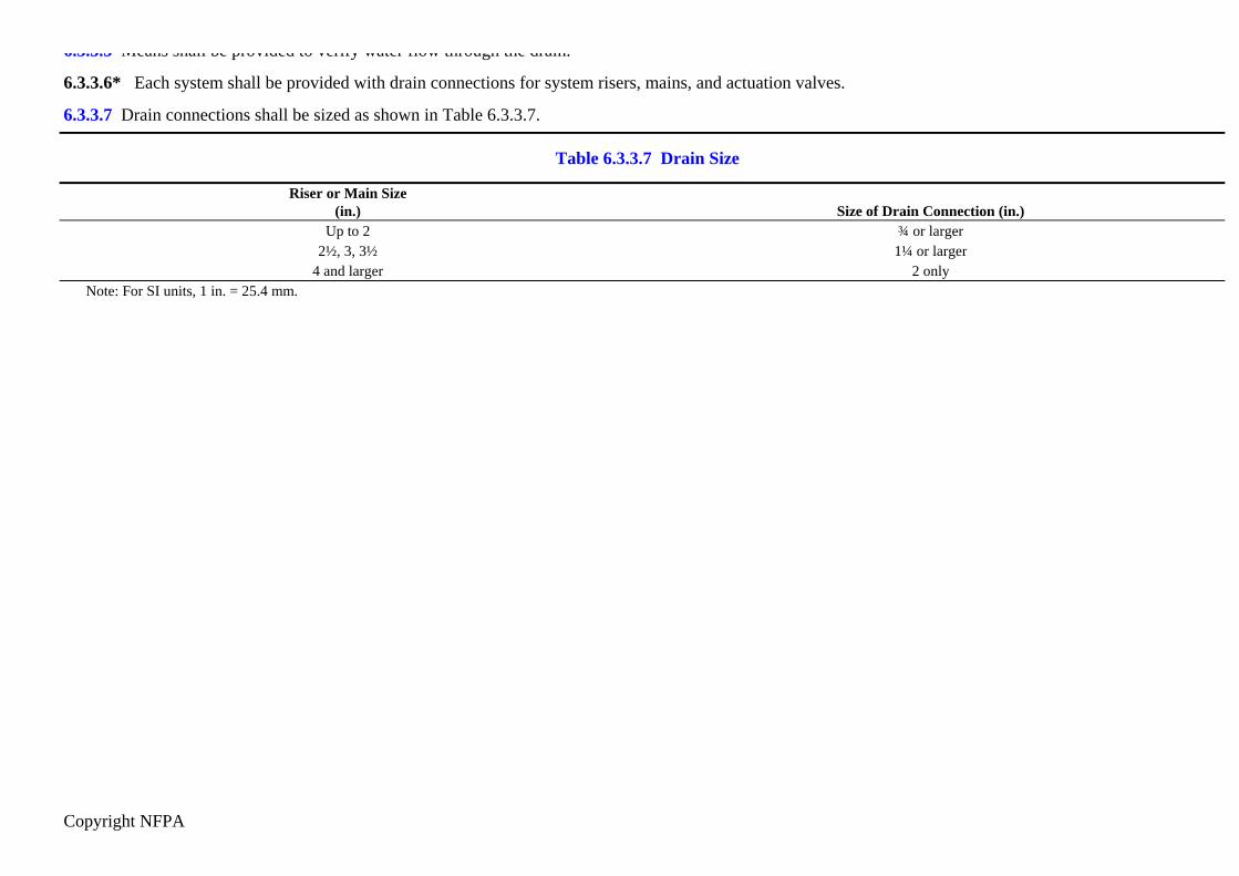
6.3.3.5 Means shall be provided to verify water flow through the drain.
6.3.3.6* Each system shall be provided with drain connections for system risers, mains, and actuation valves.
6.3.3.7 Drain connections shall be sized as shown in Table 6.3.3.7.
Copyright NFPA
6.3.3.5 Means shall be provided to verify water flow through the drain.
6.3.3.6* Each system shall be provided with drain connections for system risers, mains, and actuation valves.
6.3.3.7 Drain connections shall be sized as shown in Table 6.3.3.7.
Table 6.3.3.7 Drain Size
Riser or Main Size (in.) Size of Drain Connection (in.)
Up to 2 ¾ or larger2½, 3, 3½ 1¼ or larger
4 and larger 2 onlyNote: For SI units, 1 in. = 25.4 mm.

Copyright NFPA
6.3.3.8 Auxiliary Drains.
6.3.3.8.1 Auxiliary drains shall be provided where a change in piping direction prevents drainage of system piping through either the main drain valve or openwater spray nozzles.
6.3.3.8.2 The sizing of auxiliary drains for water spray systems shall be in accordance with Table 6.3.3.8.2.
Table 6.3.3.8.2 Minimum Auxiliary Drain Size for Trapped Water Spray Piping
Volume of Trapped Pipinggal L Drain Size (in.)< 5 < 18.9 ½
5 to 50 18.9 to 189.3 ¾> 50 > 189.3 1.0
Note: For SI units, 1 gal = 3.8 L; 1 in. = 25.4 mm.
6.3.4 Protection Against Freezing.
6.3.4.1 Where used, valve rooms shall be lighted and heated.
6.3.4.2 The source of heat shall be of a permanently installed type and shall be capable of maintaining a room temperature at a minimum of 40°F (4°C).
6.3.4.3 Where water-filled supply pipes, risers, system risers, or feed mains pass through open areas, cold rooms, passageways, or other areas exposed tofreezing, the pipe shall be protected against freezing by insulating coverings, frostproof casing, or other means capable of maintaining a minimum temperature of40°F (4°C).
6.3.4.4 Unheated areas shall be permitted to be protected by antifreeze systems in accordance with NFPA 13, Standard for the Installation of Sprinkler Systems,if acceptable to the authority having jurisdiction.
6.3.5 Protection Against Damage Where Subject to Earthquakes. Protection of piping against damage where subject to earthquakes shall be in accordancewith NFPA 13, Standard for the Installation of Sprinkler Systems.
6.3.6* Protection of Piping Against Damage Where Explosion Potential Exists. Where water spray systems are installed in areas having an explosionpotential, they shall be installed in a manner that will minimize damage to the piping and system control and actuation valves.
6.4 System Attachments.
Copyright NFPA
6.4.1 Alarms.
6.4.1.1 All automatic water spray systems shall be provided with a local alarm.
6.4.1.2 Any flow from a single automatic nozzle of the smallest orifice size installed on the system or flow from any group of nonautomatic nozzles shall resultin an audible alarm on the premises within 90 seconds after flow begins.
6.4.1.3 Where a separate detection system is used to activate the water spray system, the alarm shall be actuated independently of system water flow to indicateoperation of the detection system.
6.4.1.4 Waterflow alarms shall be installed in accordance with NFPA 13, Standard for the Installation of Sprinkler Systems.
6.4.1.5 Electrically operated alarm attachments shall be installed in accordance with NFPA 72, National Fire Alarm Code.
6.4.1.6 Water spray system waterflow alarm systems that are not a part of a required protective signaling system shall not be required to be supervised, but shallbe installed in accordance with Article 760 of NFPA 70, National Electrical Code.
6.4.2 Remote Manual Actuation.
6.4.2.1 At least one manual actuation device independent of the manual actuation device at the system actuation valve shall be installed for all automaticsystems.
6.4.2.2 Where the manual release at the systems actuation valve meets the requirements of 6.4.2.1, a separate remote manual activation device shall not berequired.
6.4.2.3 Systems that protect normally unoccupied areas shall not require a separate manual activation means.
6.4.2.4 Remote manual actuation devices shall be located so as to be accessible during an emergency.
6.4.2.5 Remote manual actuation devices shall be identified with a permanently marked weatherproof metal or rigid plastic sign identifying the system(s)controlled.
6.4.3* Fire Department Connections.
6.4.3.1* One or more fire department connections shall be provided as described in this subsection.
6.4.3.2 Fire department connections shall not be required for the following installations:
(1) Systems located in remote areas that are inaccessible for fire department support shall not require a fire department connection.
(2) Large capacity systems exceeding the pumping capacity of the fire department shall not require a fire department connection.
(3) Ultra high-speed water spray systems shall not require a fire department connection.

Copyright NFPA
6.4.3.3 The number of outlets and size of the outlets and piping in the fire department connection shall be sufficient to supply the water spray system demand.
6.4.3.4 The arrangement and other installation features of fire department connections shall be in accordance with NFPA 13, Standard for the Installation ofSprinkler Systems.
6.4.4 Gauges.
6.4.4.1 Pressure gauges shall be installed as follows:
(1) Below the system actuation valve
(2) Above and below alarm check valves
(3) On the air or water supply to pilot lines
6.4.4.2 Pressure gauges shall be installed so as to permit removal.
6.4.4.3 Pressure gauges shall be located where they will not be subject to freezing.
6.4.4.4 Provisions shall be made for test gauges at or near the highest or most remote nozzle on each separate section of the system.
6.4.4.5 At least one gauge connection shall be provided at or near the nozzle calculated as having the least pressure under normal flow conditions.
6.4.5 Alarm Test Connection for Wet Pipe Systems. An alarm test connection shall be provided for all wet pipe systems in accordance with NFPA 13,Standard for the Installation of Sprinkler Systems.
6.4.6 Strainers.
6.4.6.1* Main pipeline strainers shall be provided for all systems utilizing nozzles with waterways less than in. (9.5 mm) and for any system where the wateris likely to contain obstructive material.
6.4.6.2 Mainline pipeline strainers shall be installed so as to be accessible for flushing or cleaning.
6.4.6.3 Individual or integral strainers shall be provided at each nozzle where waterways smaller than in. (5 mm) are used.
6.5 Automatic Detection Equipment.
6.5.1 Protection.
6.5.1.1 Corrosion Protection. Detection equipment installed outdoors or in the presence of possible corrosive vapors or atmospheres shall be protected fromcorrosion by suitable materials of construction or by suitable protection coatings applied by the equipment manufacturer.
6.5.1.2 Protective Canopy. Detection equipment requiring protection from the weather shall be provided with a canopy, hood, or other suitable protection.
Copyright NFPA
6.5.1.3* Mechanical Damage. Detection equipment shall be located so as to be protected from mechanical damage.
6.5.1.4 Mounting. Detectors shall, in all cases, be supported independently of their attachment to wires or tubing.
6.5.1.5 Pilot Sprinklers. Pilot type automatic sprinklers shall be permitted to be supported by their piping or tubing.
6.5.2 Selection, Location, and Spacing of Detectors.
6.5.2.1 The selection, location, and spacing of automatic fire detectors for the actuation of fixed water spray systems shall meet or exceed the applicablerequirements of NFPA 72, National Fire Alarm Code, and be consistent with the following:
(1) Data obtained from field experience
(2) Tests
(3) Engineering surveys
(4) Manufacturer’s recommendations
(5) Detectors’ listing criteria
(6) Nature of the hazard being protected
(7) Both normal and abnormal air velocities
(8) Range of anticipated temperatures
(9) Maximum expected rates of temperature change under nonfire conditions
(10) Number and height of structural levels
(11) Effects of precipitation (rain and snow)
(12) Presence and magnitude of electromagnetic interference
(13) Presence of obstructions that might retard or mitigate timely detection
(14) Other conditions that might affect the efficacy of the fire detection employed
6.5.2.2 Detectors shall be located so as to promptly respond to a fire, flammable gas release, or other design condition.
6.5.2.2.1 The detection system shall be capable of detecting a fire up to the elevation of the highest level of protected equipment surface.
6.5.2.2.2 Detectors shall be located so that no portion of the hazard being protected extends beyond the perimeter line of detectors.

Copyright NFPA
6.5.2.3* Outdoor Detector Spacing.
6.5.2.3.1 Where located out of doors or in the open, the spacing of fixed temperature or rate-of-rise detectors shall be reduced by at least 50 percent from thelisted spacings under smooth ceilings.
6.5.2.3.2 Where testing has demonstrated acceptable performance at other spacings, those spacings shall be permitted.
6.5.2.3.3 Pilot sprinklers spaced in accordance with 6.5.2.4 shall not require reduced spacing.
6.5.2.3.4 Where specific guidance is provided in the listing, detectors specifically listed for outdoor installation shall be installed in accordance with the listingrequirements.
6.5.2.4 Pilot-Type Sprinklers.
6.5.2.4.1 The temperature rating of pilot-type sprinklers shall be selected in accordance with NFPA 13, Standard for the Installation of Sprinkler Systems.
6.5.2.4.2 Where located under a ceiling, pilot sprinklers shall be positioned in accordance with the requirements for automatic sprinklers in NFPA 13, Standardfor the Installation of Sprinkler Systems.
6.5.2.4.3 Maximum horizontal spacing for indoor locations shall not exceed 12 ft (3.7 m).
6.5.2.4.4 The obstruction to water distribution rules for automatic sprinklers shall not be required to be followed where pilot sprinklers are used.
6.5.2.4.5 Pilot sprinklers shall be permitted to be spaced more than 22 in. (559 mm) below a ceiling or deck where the maximum spacing between pilotsprinklers is 10 ft (3 m) or less.
6.5.2.4.6 Other maximum horizontal pilot sprinkler spacings differing from those required in 6.5.2.4.2 and 6.5.2.4.3 shall be permitted where they are installedin accordance with their listing.
6.5.2.4.7 Pilot sprinklers located outdoors, such as in open process structures, shall be spaced such that the elevation of a single level of pilot sprinklers andbetween additional levels of pilot sprinklers shall not exceed 17 ft (5.2 m).
6.5.2.4.8 The horizontal distance between pilot sprinklers installed outdoors shall not exceed 8 ft (2.5 m).
6.5.2.4.9 The horizontal distance between pilot sprinklers installed outdoors on a given level shall be permitted to be increased to 10 ft (3 m) where the elevationof the first level does not exceed 15 ft (4.6 m), the distance between additional levels does not exceed 12 ft (3.7 m), and the pilot sprinklers are staggeredvertically.
6.5.2.4.10 Other vertical pilot sprinkler spacings differing from those required in 6.5.2.4.7 and 6.5.2.4.8 shall be permitted where installed in accordance withtheir listing.
6.5.2.5 Special Situations.
Copyright NFPA
6.5.2.5.1 Open-Sided Buildings.
6.5.2.5.1.1 Detectors located in open-sided buildings shall follow the indoor spacing rules.
6.5.2.5.1.2 A line of detectors in accordance with the outdoor detector spacing rules shall be located along the open sides of open-sided buildings.
6.5.2.5.2 Under Open Gratings. Detectors located under open gratings shall be spaced in accordance with 6.5.2.3.
6.5.2.6 Two or More Systems. Where there are two or more adjacent water spray systems in one area controlled by separate detection systems, the detectors oneach system shall be spaced independently as if the dividing line between the systems were a wall or draft curtain.
6.5.2.7* Flammable Gas Detectors.
6.5.2.7.1 Flammable gas detectors shall be located with consideration for the density of the flammable gas and its temperature and proximity to equipmentwhere leakage is more likely to occur.
6.5.2.7.2 Access for testing, calibration, and maintenance of flammable gas detectors shall be provided.
6.5.2.8 Radiant Energy-Sensing Fire Detectors. Radiant energy-sensing fire detectors shall be spaced and located in accordance with their listings andmanufacturer’s recommendations.
6.5.3 Arrangement and Supervision of Systems.
6.5.3.1 Electrical Systems.
6.5.3.1.1 Water spray systems that depend on electric thermostats, relay circuits, flammable gas detectors, or other similar equipment shall be so arranged thatsuch equipment is normally energized or completely supervised in a manner that will result in positive notifications on an abnormal condition in accordance withNFPA 72, National Fire Alarm Code, unless failure of the detection system results in the operation of the water spray system.
6.5.3.1.2 Supervision shall include, but not be limited to, the tripping device, solenoid valve, and any connecting wiring.
6.5.3.2 Pneumatic and Hydraulic Systems. Pneumatically and hydraulically operated systems shall be supervised in a manner such that failure will result inpositive notification of the abnormal condition, unless the failure results in operation of the water spray system.
Chapter 7 Design Objectives
7.1 System Design.
7.1.1 Systems shall be arranged for automatic operation with supplementary manual tripping means provided.
7.1.2 Manual operation shall be permitted where automatic operation of the system presents a hazard to personnel.

Copyright NFPA
7.1.3 Manual operation of the system shall be permitted where a system is isolated and attended by trained personnel at all times.
7.1.4 Systems shall be designed to accomplish at least one of the design objectives defined in Section 4.1 and in accordance with Sections 7.2 through 7.5, asapplicable.
7.1.5 Systems shall be permitted to have other design objectives requiring different protection where approved by the authority having jurisdiction.
7.1.6* The system and water supplies shall be designed to admit water into the piping and to discharge effective water spray from all open nozzles withoutdelay.
7.1.7 The design shall ensure that the nozzle spray patterns meet or overlap.
7.1.8 Nozzle spacing (vertically or horizontally) shall not exceed 10 ft (3 m).
7.1.9 Nozzles shall be permitted to exceed the spacing requirements of 7.1.8 where listed for spacing exceeding 10 ft (3 m).
7.1.10 Size of System and Water Demand.
7.1.10.1* A single system shall not protect more than one fire area.
7.1.10.2* The number of systems expected to operate simultaneously shall be determined by evaluating the following factors:
(1) Possible flow of burning liquids between areas before or during operation of the water spray systems
(2) Possible flow of hot gases between fire areas that could actuate adjoining systems, thereby increasing demand
(3) Flammable gas detection set to automatically actuate systems
(4) Manual operation of multiple systems
(5) Other factors that would result in operation of systems outside of the primary fire area
7.1.10.3 The hydraulically designed discharge rate for a single system or multiple systems designed to operate simultaneously shall not exceed the availablewater supply. (See 9.2.1.)
7.2 Extinguishment.
7.2.1 General.
7.2.1.1 Design Objective. Systems shall be designed so that extinguishment shall be accomplished and all protected surfaces shall be cooled to prevent flashbackoccurring after the system is shut off.
7.2.1.2* Extinguishment Methods. Extinguishment of fires by water spray shall be accomplished by one or a combination of the following methods:
Copyright NFPA
(1) Surface cooling
(2) Smothering by produced steam
(3) Emulsification
(4) Dilution
(5) Other factors
7.2.1.3* Design Density. A general range of water spray application rates that shall apply to most ordinary combustible solids or liquids shall be from 0.15gpm/ft2 to 0.50 gpm/ft 2 [6.1 (L/min)/m2 to 20.4 (L/min)/m2] of protected surface.
7.2.1.3.1 The specific design density for extinguishment shall be based on test data or knowledge concerning conditions similar to those that will apply in theactual installation.
7.2.2 Cable Trays and Cable Runs.
7.2.2.1* Where insulated wire and cable or nonmetallic tubing is to be protected by an automatic water spray (open nozzle) system designed for extinguishmentof fire that originates within the cable or tube, the system shall be hydraulically designed to impinge water directly on each tray or group of cables or tubes at anet rate of 0.15 gpm/ft2 [6.1 (L/min)/m2] on the projected plane containing the cable or tubing tray or run.
7.2.2.2 Cable trays and cable runs shall be permitted to be protected by other water spray densities and methods of application where verified by tests and whereacceptable to the authority having jurisdiction.
7.2.2.3* Automatic detection devices shall detect smoldering or slow-to-develop flames.
7.2.2.4 Where it is likely that spills of flammable liquids or molten materials will expose cables, nonmetallic tubing, and tray supports, the design of protectionsystems shall be in accordance with that specified for exposure protection. (See 7.4.3.8.)
7.2.3 Belt Conveyors.
7.2.3.1 General.
7.2.3.1.1 Open nozzles shall be located to direct water spray onto the surfaces to extinguish fire in hydraulic oil, the belt, the contents on the belt, or the driveunit.
7.2.3.1.2 Water spray impingement on structural elements shall provide exposure protection against radiant heat or impinging flame.
7.2.3.1.3 Interlocks shall be provided between the detection system and the machinery to shut down belt conveyor operation, including upstream feed. (SeeSections 6.5 and 7.7.)
7.2.3.1.4 The water supply shall be capable of supplying both the design flow rate and 250 gpm (946 L/min) for hose streams for a minimum duration of 1 hour.
Copyright NFPA
7.2.3.2* Drive Unit.
7.2.3.2.1 The water spray system shall be installed to protect the drive rolls, the take-up rolls, the power units, and the hydraulic-oil unit.
7.2.3.2.2 The net rate of water application for the drive unit shall be not less than 0.25 gpm/ft2 [10.2 (L/min)/m2] of roll and belt.
7.2.3.3 Conveyor Belt.
7.2.3.3.1* The water spray system shall be installed to automatically wet the top belt, its contents, and the bottom return belt.
7.2.3.3.2 Discharge patterns of water spray nozzles shall envelop, at a net rate of not less than 0.25 gpm/ft2 [10.2 (L/min)/m2], the top and bottom belt surfacearea, conveyor surfaces where combustible materials are likely to accumulate, the structural parts, and the idler rolls supporting the belt.
7.2.3.3.3 Water spray system protection for belt conveyors shall accomplish either of the following:
(1) Extend onto transfer belts, transfer equipment, and transfer building
(2) Interlock in such a manner that the water spray system protecting the feeding belt will automatically actuate the water spray system protecting the firstsegment of the downstream equipment
7.3 Control of Burning.
7.3.1 General.
7.3.1.1* A system for the control of burning shall operate as intended until there has been time for the burning material to be consumed, for steps to be taken toshut off the flow of leaking material, or until the burning material can be otherwise extinguished.
7.3.1.2 Nozzles shall be positioned to impinge water directly on the areas of the source of fire and where spills are likely to spread or accumulate.
7.3.1.3 The water application rate shall be at a net rate of not less than 0.50 gpm/ft2 [20.4 (L/min)/m2] of protected area.
7.3.2* Pumps, Compressors, and Related Equipment. Pumps or other devices that handle flammable liquids or gases shall have the shafts, seals, and othercritical parts enveloped by directed water spray at a net rate of not less than 0.50 gpm/ft2 [20.4 (L/min)/m2] of projected surface area of the equipment.
7.3.3 Flammable and Combustible Liquid Pool Fires. Water spray systems designed to control pool fires resulting from a flammable or combustible liquidspill fire shall be designed to apply a net rate of not less than 0.30 gpm/ft2 [12.2 (L/min)/m2] of protected area.
7.3.3.1 Subsection 7.3.3 shall apply to the control of pool fires resulting from a flammable or combustible liquid spill.
7.3.3.2 The water spray system shall be designed to apply a net rate of not less than 0.30 gpm/ft2 [12.2 (L/min)/m2] of protected area.
7.4 Exposure Protection.

Copyright NFPA
7.4.1* General. A system for exposure protection shall operate as intended for the anticipated duration of the exposure fire.
7.4.2* Vessels.
7.4.2.1 Water spray shall be applied to vessel surfaces (including top and bottom surfaces of vertical vessels) at a net rate of not less than 0.25 gpm/ft2 [10.2(L/min)/m2] of exposed surface.
7.4.2.2* Where rundown is contemplated, the distance between nozzles at different levels or elevations, protecting vertical or inclined surfaces, shall not exceed12 ft (3.7 m) as measured along the surface.
7.4.2.3* The horizontal distance between nozzles shall be such that spray patterns meet or overlap at the protected surface.
7.4.2.4 Spherical or horizontal cylindrical surfaces below the vessel equator shall not be considered wettable from rundown.
7.4.2.5 Where projections (manhole flanges, pipe flanges, support brackets, relief valves, etc.) will obstruct water spray coverage, including rundown on verticalsurfaces, additional nozzles shall be installed around the projections to maintain the wetting pattern that otherwise would be seriously interrupted.
7.4.2.6 All uninsulated vessel skirts and any uninsulated steel saddles greater than 12 in. (305 mm) high at the lowest point shall have water spray applied onone exposed (uninsulated) side, at a net rate of not less than 0.25 gpm/ft2 [10.2 (L/min)/m2].
7.4.3 Structures and Miscellaneous Equipment.
7.4.3.1* Horizontal Structural Steel. Horizontal, stressed (primary) structural steel members shall be protected by nozzles and piping of such size andarrangement to discharge a net rate of not less than 0.10 gpm/ft2 [4.1 (L/min)/m2] over the wetted area, as per Figure 7.4.3.1.
FIGURE 7.4.3.1 Wetted Surface of a Structural Member (a beam or column).
7.4.3.2 Horizontal structural steel that has been encased in fire-resistant insulating material to provide a level of fire resistance acceptable to the authority havingjurisdiction shall not require water spray protection.
7.4.3.3 Alternative Engineering Analysis for Horizontal Structural Steel. Horizontal structural steel shall not require water spray exposure protection whereall of the following are met:
(1) Horizontal structural steel shall be analyzed and determined, through calculations certified by a registered professional engineer, to withstand theworst-case postulated fire.

Copyright NFPA
(2) Calculations shall verify that the temperature of the steel members does not exceed that which would compromise structural integrity.
(3) The calculation methodology shall be approved and acceptable to the authority having jurisdiction.
7.4.3.4* Vertical Structural Steel. Vertical structural steel members shall be protected by nozzles and piping of such size and arrangement as to discharge a netrate of not less than 0.25 gpm/ft2 [10.2 (L/min)/m2] over the wetted area. (See Figure 7.4.3.1.)
7.4.3.5 Vertical structural steel that has been encased in fire-resistant insulating material to provide a level of fire resistance acceptable to the authority havingjurisdiction shall not require water spray protection.
7.4.3.6 Alternative Engineering Analysis for Vertical Structural Steel. Vertical structural steel shall not require water spray exposure protection where all ofthe following are met:
(1) Vertical structural steel shall be analyzed and determined, through calculations certified by a registered professional engineer, to withstand the worst-casepostulated fire.
(2) Calculations shall verify that the temperature of the steel members does not exceed that which would compromise structural integrity.
(3) The calculation methodology shall be approved and acceptable to the authority having jurisdiction.
7.4.3.7 Metal Pipe, Tubing, and Conduit.
7.4.3.7.1 Water spray intended to protect metal pipe, tubing, and conduit in racks shall be directed toward the underside of the pipes, tubes, and conduit.
7.4.3.7.2 Water spray protection shall be permitted to be applied to the top of pipes on racks where water spray piping cannot be installed below the rack due tothe potential of physical damage or where space is inadequate for proper installation.
7.4.3.7.3 The levels protected and the densities required shall be in accordance with Table 7.4.3.7.3.
Table 7.4.3.7.3 Protection of Metal Pipe, Tubing, and Conduit
Plan View Density at
Lowest LevelPlan View Density at
Upper Level(s)*
Number of Rack Levels gpm /ft2
(L/min) /m2
gpm /ft2
(L/min) /m2
Levels Requiring Nozzles
1 0.25 10.2 N/A N/A All2 0.20 8.2 0.15 6.1 All3, 4, or 5 0.20 8.2 0.15 6.1 Alternate6 or more 0.20 8.2 0.10 4.1 Alternate
*The table values contemplate exposure from a spill fire.

Copyright NFPA
7.4.3.7.4 Water spray shall be applied to the underside of the top level even if located immediately above a protected level.
7.4.3.7.5 Nozzles shall be selected and positioned such that spray patterns meet or overlap at the protected surface for the entire width of the rack.
7.4.3.7.6 Nozzles shall be positioned no more than 2½ ft (0.8 m) below the bottom of the level being protected.
7.4.3.7.7 Where the rack horizontal support members create an obstruction to the spray pattern, nozzles shall be spaced within the bays.
7.4.3.7.8 Vertical structural supports shall be protected in accordance with 7.4.3.4.
7.4.3.7.9 Vertically stacked piping shall be protected by water spray directed at one side (vertical plane) of the piping at a net rate of not less than 0.15 gpm/ft2
[6.1 (L/min)/m2].
7.4.3.8 Cable Trays and Cable Runs.
7.4.3.8.1 Where insulated wire, cable, or nonmetallic tubing in open trays or runs is to be protected by water spray from a spill fire exposure, a net rate of notless than 0.30 gpm/ft2 [12.2 (L/min)/m2] of projected horizontal or vertical plane area containing the cables or tubes shall be provided.
7.4.3.8.2 Water spray nozzles shall be arranged to supply water at this rate both over and under (or to the front and rear of) cable or tubing runs and to the racksand supports.
7.4.3.8.3 Flame Shield Use.
7.4.3.8.3.1 Where flame shields equivalent to in. (1.6 mm) thick steel plate are mounted below cable or tubing runs, the water density requirements shall bepermitted to be reduced to a net rate of not less than 0.15 gpm/ft2 [6.1 (L/min)/m2] over the upper surface of the cable or rack.
7.4.3.8.3.2 The steel plate or equivalent flame shield shall be wide enough to extend at least 6 in. (152 mm) beyond the side rails of the tray or rack in order todeflect flames or heat emanating from spills below cable or conduit runs.
7.4.3.8.4 Where other water spray nozzles are arranged to extinguish, control, or cool exposing liquid surfaces, the water spray density shall be permitted to bereduced to a net rate of not less than 0.15 gpm/ft2 [6.1 (L/min)/m2] over the upper surface, front, or back of the cable or tubing tray or run.
7.4.4 Transformers.
7.4.4.1* Transformer protection shall provide complete water spray impingement on all exposed exterior surfaces.
7.4.4.2 Where there is insufficient space to install water spray nozzles underneath transformers such that the water spray cannot directly impinge upon thebottom surfaces, it shall be permitted to protect the surfaces underneath the transformer by horizontal projection or by nozzles directed to cool the area below thetransformer projections.
7.4.4.3 Application and Protection.

Copyright NFPA
7.4.4.3.1 The water shall be applied at a net rate not less than 0.25 gpm/ft2 [10.2 (L/min)/m2] of projected area of rectangular prism envelope for the transformerand its appurtenances, and not less than 0.15 gpm/ft2 [6.1 (L/min)/m2] on the expected nonabsorbing ground surface area of exposure.
7.4.4.3.2 The water shall be applied at a net rate of not less than 0.15 gpm/ft2 [6.1(L/min)/m2] on the expected nonabsorbing ground surface area of exposure.
7.4.4.3.3 Water spray application as specified in 7.4.4.3.1 and 7.4.4.3.2 shall be provided for special configurations, conservator tanks, pumps, and so forth.
7.4.4.3.4 Where transformer components create spaces greater than 12 in. (305 mm) in width, the surfaces shall be individually protected.
7.4.4.3.5 Where there is insufficient clearance to achieve direct impingement, it shall be permitted to protect the surfaces underneath the transformer byhorizontal projection or by nozzles directed to cool the area below the transformer projections.
7.4.4.3.6 The water supply shall be capable of supplying both the design flow rate and 250 gpm (946 L/min) for hose streams for a minimum duration of 1 hour.
7.4.4.4 Water spray piping shall not be routed across the top of the transformer tank or across the face of the transformer cabinet.
7.4.4.5 Piping shall be permitted to be routed across the top of the transformer tank or across the face of the transformer cabinet, where impingement cannot beaccomplished with any other configuration and the required distance from live electrical components is maintained. (See 6.1.2.)
7.4.4.6 Nozzles shall be positioned such that the water spray does not envelop energized bushings or lightning arresters by direct impingement.
7.4.4.7 Direct impingement of water spray on energized bushings and/or lightning arresters shall be permitted only when authorized by the manufacturer ormanufacturer’s literature and the owner.
7.5* Prevention of Fire.
7.5.1 The system shall operate as intended for the time necessary to dissolve, dilute, disperse, or cool flammable vapor, gases, or hazardous materials.
7.5.2 The duration of release of the flammable materials shall be included in the determination of the water spray duration time.
7.5.3 The minimum net rate of application shall be based upon field experience with the product or upon actual test data.
7.6 Combined Systems.
7.6.1* General.
7.6.1.1 The sprinkler system portion of combined systems shall be designed and installed in accordance with NFPA 13, Standard for the Installation ofSprinkler Systems.
7.6.1.2 The water spray portion of any combined system shall be designed and installed in accordance with this standard.
7.6.2* Design.

Copyright NFPA
7.6.2.1 The system demand shall include the simultaneous hydraulic demand from all sprinklers and water spray nozzles on the system.
7.6.2.2 The water spray component of the combined demand shall not reduce the minimum required sprinkler discharge density.
7.7 Automatic Detection Equipment.
7.7.1* General. Detection systems providing an actuation signal to fixed water spray systems shall be designed in accordance with NFPA 72, National FireAlarm Code.
7.7.2 The spacing, location, and position of detectors shall be in accordance with 6.5.2.
7.7.3* The following shall be evaluated when selecting and adjusting detection equipment:
(1) Normally changing conditions
(2) Non-fire temperature changes
7.7.4* Response Time.
7.7.4.1 The detection system shall be designed to cause actuation of the system actuation valve to operate without delay.
7.7.4.2 Where ambient conditions exist that cause false system operations, detection systems shall be permitted to include delays that would override theseconditions.
Chapter 8 Plans and Hydraulic Calculations
8.1 General.
8.1.1* Hydraulic calculations shall be conducted as part of the design of the piping system to determine that the required pressure and flow is available at eachnozzle.
8.1.2* Minimum operating pressure of any nozzle protecting outdoor hazard shall be 20 psi (1.4 bar).
8.1.3 Nozzles protecting interior hazards shall have minimum operating pressures in accordance with their listing.
8.1.4* Except where permitted by 8.1.5, correction for velocity pressure shall be included in the calculations.
8.1.5* The calculations shall be permitted to ignore velocity pressure corrections where the velocity pressure does not exceed 5 percent of the total pressure ateach junction point.
8.2 Working Plans.

Copyright NFPA
8.2.1 General.
8.2.1.1 Working plans shall be submitted to the authority having jurisdiction before any equipment is installed or remodeled.
8.2.1.2 Deviation from approved plans shall require permission of the authority having jurisdiction.
8.2.1.3 Working plans, including elevations, shall be drawn to an indicated scale, show all essential details, and include the following pertinent data as aminimum:
(1) The dates of initial submission and revisions.
(2) The name of the owner and occupant.
(3) The name and address of the contractor and layout technician.
(4) The location, including the street address.
(5) The point of the compass.
(6) The full height cross section.
(7) The structural features.
(8) The relative elevations of nozzles, junction points, and supply or reference points.
(9) Full information concerning water supplies, including such items as pumps, underground mains, earthquake protection, and flow test results.
(10) The make, type, size, location, position, and direction of spray nozzles.
(11) The make, type, model, and size of the system actuation valve, control valve, or special system valve. The method of control valve supervision shall beindicated on the plans.
(12) The type and location of alarm devices to be provided. The type and location of the control panel.
(13) The number of each size and type of spray nozzles on each system.
(14) The type of pipe and schedule of wall thickness, lengths of pipe, and whether center to center or cutting lengths are shown.
(15) The size and type of all fittings; the dimensions and locations of shop-welded sections.
(16) The sensing devices for detection, including the type, arrangement, and location.
(17) The hydraulic reference points shown on the plan shall correspond to comparable reference points on the hydraulic calculation sheets.
(18) The calculated system demand at a reference point.
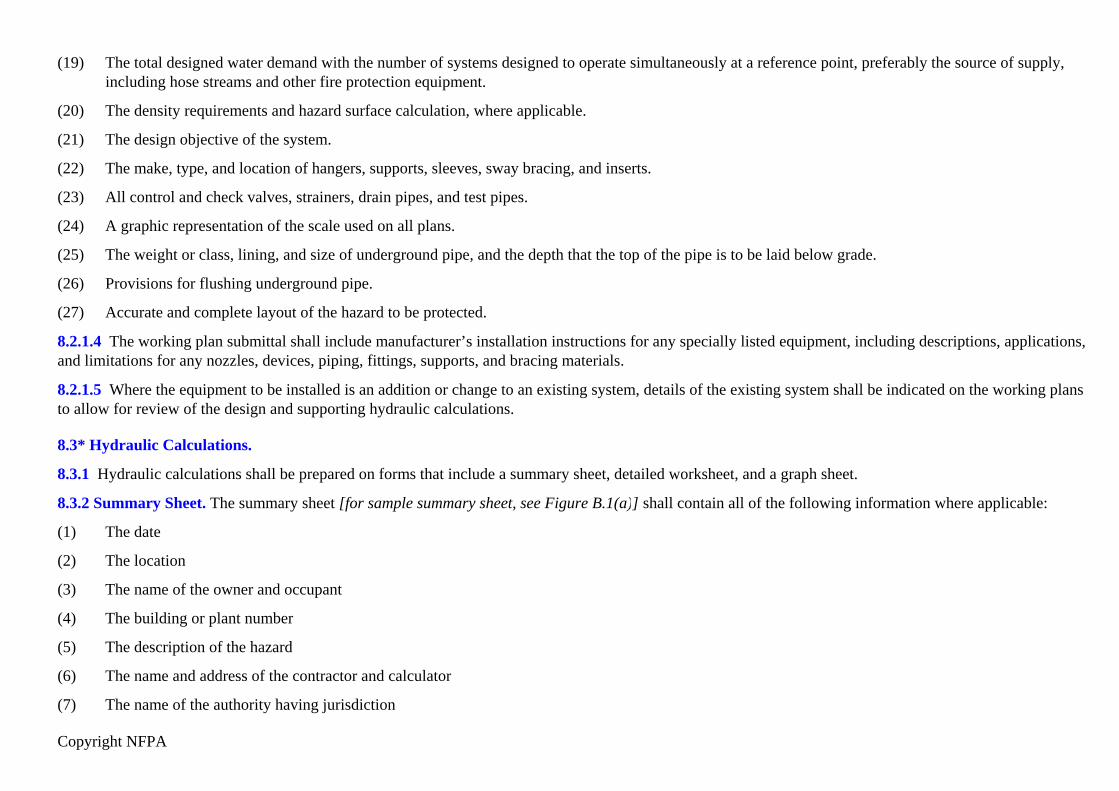
Copyright NFPA
(19) The total designed water demand with the number of systems designed to operate simultaneously at a reference point, preferably the source of supply,including hose streams and other fire protection equipment.
(20) The density requirements and hazard surface calculation, where applicable.
(21) The design objective of the system.
(22) The make, type, and location of hangers, supports, sleeves, sway bracing, and inserts.
(23) All control and check valves, strainers, drain pipes, and test pipes.
(24) A graphic representation of the scale used on all plans.
(25) The weight or class, lining, and size of underground pipe, and the depth that the top of the pipe is to be laid below grade.
(26) Provisions for flushing underground pipe.
(27) Accurate and complete layout of the hazard to be protected.
8.2.1.4 The working plan submittal shall include manufacturer’s installation instructions for any specially listed equipment, including descriptions, applications,and limitations for any nozzles, devices, piping, fittings, supports, and bracing materials.
8.2.1.5 Where the equipment to be installed is an addition or change to an existing system, details of the existing system shall be indicated on the working plansto allow for review of the design and supporting hydraulic calculations.
8.3* Hydraulic Calculations.
8.3.1 Hydraulic calculations shall be prepared on forms that include a summary sheet, detailed worksheet, and a graph sheet.
8.3.2 Summary Sheet. The summary sheet [for sample summary sheet, see Figure B.1(a)] shall contain all of the following information where applicable:
(1) The date
(2) The location
(3) The name of the owner and occupant
(4) The building or plant number
(5) The description of the hazard
(6) The name and address of the contractor and calculator
(7) The name of the authority having jurisdiction

Copyright NFPA
(8) The design purpose
(9) The rates of the water application (density) and applied areas in gpm/ft2 [L/min)/m2]
(10) The total system water requirements as calculated, including allowance for hose streams
(11) The total designed water demand with number of systems designed to operate simultaneously at a reference point, preferably the source of supply,including hose streams and other fire protection equipment
(12) Water supply information
8.3.3 Detailed Worksheets. Detailed worksheets or computer printout sheets [for sample worksheet, see Figure B.1(b)] shall contain all of the followinginformation:
(1) Sheet number, date, job number, and identification of calculations covered
(2) Description of discharge constant (K) (or provide the discharge curve or tabulation) for each nozzle type
(3) Hydraulic reference points
(4) Flow in gpm (L/min)
(5) Pipe size in in. (mm)
(6) Pipe lengths, center to center of fittings (or cut lengths) in ft (m)
(7) Equivalent pipe lengths for fittings and devices in ft (m)
(8) Friction loss in psi (bar) between reference points
(9) Total friction loss in psi (bar) between reference points
(10) Elevation head in psi (bar) between reference points
(11) Required pressure in psi (bar) at each reference point
(12) Velocity pressure and normal pressure if included in calculations
(13) Notes to indicate starting points, reference to other sheets, or to clarify data shown
(14) Combined K-factor calculations for nozzles on drops, armovers, or sprigs where calculations do not begin at a nozzle
(15) Where extending existing equipment, hydraulic calculations indicating the previous design, volume, and pressure at points of connection, and adequateadditional calculations to indicate effect on existing systems

Copyright NFPA
8.3.4* Graph Sheet.
8.3.4.1 The graph sheet shall be plotted on semi-logarithmic graph paper (Q 1.85).
8.3.4.2 Water supply curves and system requirements, plus hose demand if required, shall be plotted to present a graphic summary of the complete hydrauliccalculation.
8.4 Water Supply Information.
The following information shall be included on the plans and calculations:
(1) Location and elevation of static and residual test gauge, with relation to the system actuation valve reference point
(2) Flow location
(3) Static pressure, psi (bar)
(4) Residual pressure, psi (bar)
(5) Flow, gpm (L/min)
(6) Date
(7) Time
(8) Source of water flow test information
(9) Other sources of water supply, with pressure or elevation
8.5 Hydraulic Calculation Procedures.
8.5.1 Formulae.
8.5.1.1 Friction Loss Formula. Pipe friction losses shall be determined on the basis of the Hazen and Williams formula,
where:
p = frictional resistance in psi per foot of pipe Q = flow in gpm C = friction loss coefficient

Copyright NFPA
d = actual internal diameter of pipe in inches or in SI units,
where:
Pm = frictional resistance in bars per meter of pipe Qm = flow in L/min C = friction loss coefficient dm = actual internal diameter in mm
8.5.1.2* Velocity Pressure Formula. The velocity pressure shall be determined on the basis of the formula,
where:
Pv = velocity pressure in psiQ = flow in gpmD = inside diameter in inches
8.5.1.3 Normal Pressure Formula. Normal pressure shall be determined on the basis of the formula,
where:
Pn = normal pressure in psi (bar) Pt = total pressure in psi (bar) Pv = velocity pressure in psi (bar)
8.5.1.4 Hydraulic Junction Points.
8.5.1.4.1 Hydraulic junction point calculations shall be balanced within 0.5 psi (0.03 bar).
8.5.1.4.2 The highest pressure at the junction point, and the total flows as adjusted, shall be carried into the calculations.
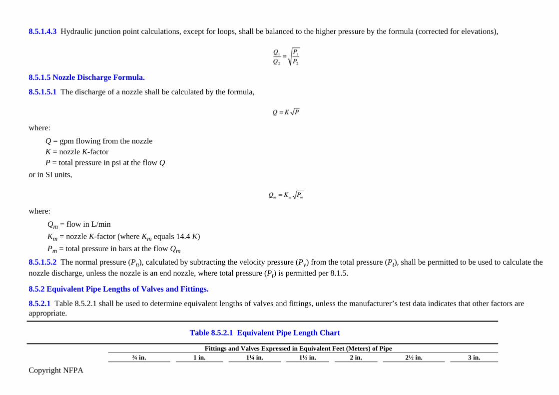
Copyright NFPA
8.5.1.4.3 Hydraulic junction point calculations, except for loops, shall be balanced to the higher pressure by the formula (corrected for elevations),
8.5.1.5 Nozzle Discharge Formula.
8.5.1.5.1 The discharge of a nozzle shall be calculated by the formula,
where:
Q = gpm flowing from the nozzleK = nozzle K-factorP = total pressure in psi at the flow Q
or in SI units,
where:
Qm = flow in L/min Km = nozzle K-factor (where Km equals 14.4 K) Pm = total pressure in bars at the flow Qm
8.5.1.5.2 The normal pressure (Pn), calculated by subtracting the velocity pressure (Pv) from the total pressure (Pt), shall be permitted to be used to calculate thenozzle discharge, unless the nozzle is an end nozzle, where total pressure (Pt) is permitted per 8.1.5.
8.5.2 Equivalent Pipe Lengths of Valves and Fittings.
8.5.2.1 Table 8.5.2.1 shall be used to determine equivalent lengths of valves and fittings, unless the manufacturer’s test data indicates that other factors areappropriate.
Table 8.5.2.1 Equivalent Pipe Length Chart
Fittings and Valves Expressed in Equivalent Feet (Meters) of Pipe¾ in. 1 in. 1¼ in. 1½ in. 2 in. 2½ in. 3 in.

Copyright NFPA
appropriate.
Table 8.5.2.1 Equivalent Pipe Length Chart
Fittings and Valves Expressed in Equivalent Feet (Meters) of Pipe¾ in. 1 in. 1¼ in. 1½ in. 2 in. 2½ in. 3 in.
Fittings and Valves ft m ft m ft m m ft ft m ft m ft m45° Elbow 1 0.3 1 0.3 1 0.3 2 0.6 2 0.6 3 0.9 3 0.990° Standard elbow 2 0.6 2 0.6 3 0.9 4 1.2 5 1.5 6 1.8 7 2.190° Long turn elbow 1 0.3 2 0.6 2 0.6 2 0.6 3 0.9 4 1.2 5 1.5Tee or cross (flow turned90°)
4 1.2 5 1.5 6 1.8 8 2.4 10 3.1 12 3.7 15 4.6
Gate valve — — — — — — — — 1 0.3 1 0.3 1 0.3Butterfly valve — — — — — — — — 6 1.8 7 2.1 10 3.1Swing check* 4 1.2 5 1.5 7 2.1 9 2.7 11 3.4 14 4.3 16 4.9
Fittings and Valves Expressed in Equivalent Feet (Meters) of Pipe
Fittings and Valves3½ in. 4 in. 5 in. 6 in. 8 in. 10 in. 12 in.
ft m ft m ft m ft m ft m ft m ft m45° Elbow 3 0.9 4 1.2 5 1.5 7 2.1 9 2.7 11 3.4 13 4.090° Standard elbow 8 2.4 10 3.1 12 3.7 14 4.3 18 5.5 22 6.7 27 8.290° Long turn elbow 5 1.5 6 1.8 8 2.4 9 2.7 13 4.0 16 4.9 18 5.5Tee or cross (flow turned90°)
17 5.2 20 6.1 25 7.6 30 9.2 35 10.7 50 15.3 60 18.3
Gate valve 1 0.3 2 0.6 2 0.6 3 0.9 4 1.2 5 1.5 6 1.8Butterfly valve — — 12 3.7 9 2.7 10 3.1 12 3.7 19 5.8 21 6.4Swing check* 19 5.8 22 6.7 27 8.2 32 9.8 45 13.7 55 16.8 65 19.8
*Due to the variations in design of swing check valves, the pipe equivalents indicated in this chart are to be considered average.Notes:(1) Use the equivalent ft (m) value for the “standard elbow” on any abrupt 90° turn such as the screw-type pattern. Use the equivalent ft (m) value for the “long turnelbow” on any sweeping 90° turn such as flanged, welded, or mechanical joint elbow type.(2) For internal pipe diameters different from Schedule 40 steel pipe, the equivalent feet shown shall be multiplied by a factor derived from the following formula:
8.5.2.2 Specific friction loss values or equivalent pipe lengths for system actuation valves and other devices shall be made available to the authority having

Copyright NFPA
jurisdiction.
8.5.2.3 Table 8.5.2.1 shall be used with a Hazen-Williams C factor of 120 only. For other values of C, the figures in Table 8.5.2.1 shall be multiplied by thefollowing factors:Value of C 100 120 130 140 150Multiplying factor 0.713 1.00 1.16 1.33 1.51
Notes:(1) This is based upon the friction loss through the fitting being independent of the C factor applicable to the piping.(2) Specific friction loss values or equivalent pipe lengths for alarm valves, dry-pipe valves, deluge valves, strainers, and other devices or fittings should be made available to theauthority having jurisdiction.
8.5.3* Calculation Procedure.
8.5.3.1 Worksheets shall be provided to show the flow and pressure for all nozzles and junction points to the water supply.
8.5.3.2 A graph sheet shall be included with the calculations in accordance with 8.3.4.
8.5.3.3 The friction loss for all pipes, and devices such as valves, meters, and strainers, shall be included in the calculation.
8.5.3.4 A legend of the symbols used for all devices shall be included.
8.5.3.5 The loss of all fittings shall be calculated where a change in direction of the flow occurs, as follows:
(1) The loss for a tee or a cross shall be calculated where the flow direction change occurs, based upon the equivalent pipe length for the smaller size of thetee or cross in the path of the turn. Loss for that portion of the flow that passes straight through the run of a tee or a cross shall not be included.
(2) The loss of reducing elbows shall be calculated based upon the equivalent length value in feet of the smallest outlet.
(3) Friction loss shall be excluded for tapered reducers and for the fitting directly supplying the spray nozzle.
8.5.3.6 Elevation changes affecting the discharge or the total required pressure, or both, shall be included in the calculations at the point of occurrence.
8.5.3.7 The water allowance for hose stream(s), where served from the same supply, shall be added to the system requirement at the system connection to thesupply main.
8.5.3.8 The total water requirements shall then be calculated to a known water supply reference point.
8.5.3.9 Orifice plates shall not be used for balancing the system.
8.5.3.10 Pipe friction loss shall be calculated in accordance with the Hazen and Williams formula, using C values as shown in Table 8.5.3.10, and using theactual internal pipe diameter in the formula.

Copyright NFPA
8.5.3.8 The total water requirements shall then be calculated to a known water supply reference point.
8.5.3.9 Orifice plates shall not be used for balancing the system.
8.5.3.10 Pipe friction loss shall be calculated in accordance with the Hazen and Williams formula, using C values as shown in Table 8.5.3.10, and using theactual internal pipe diameter in the formula.
Table 8.5.3.10 Hazen and Williams C Value for Pipe and Tube
Pipe or TubeHazen and Williams
C ValueUnlined cast or ductile iron 100Galvanized steel (all) 120Plastic (listed) — underground 150Cement lined cast or ductile iron 140Copper tube or stainless steel 150

Copyright NFPA
8.5.3.11 Different C values shall be permitted to be used where required by the authority having jurisdiction.
Chapter 9 Water Supplies
9.1 General.
Every water spray system shall have at least one automatic water supply.
9.2 Volume and Pressure.
9.2.1 The water supplies shall be capable of providing the required flow and pressure for the required duration, including systems designed to operatesimultaneously, as specified in Chapter 7.
9.2.2 For water supply distribution systems, an allowance for the flow rate of other fire protection water requirements shall be made in determining the totalwater supply requirement.
9.3 Acceptable Water Supply Systems.
9.3.1* Water for water spray systems shall be from one or more water supplies, such as the following:
(1) Connections to waterworks systems, in accordance with NFPA 24, Standard for the Installation of Private Fire Service Mains and Their Appurtenances
(2) Gravity tanks, in accordance with NFPA 22, Standard for Water Tanks for Private Fire Protection
(3) Fire pumps with adequate water supply, in accordance with NFPA 20, Standard for the Installation of Stationary Pumps for Fire Protection
(4) Pressure tanks, in accordance with NFPA 22, Standard for Water Tanks for Private Fire Protection, and NFPA 13, Standard for the Installation ofSprinkler Systems, sized per the hydraulically calculated method
9.3.2 Installation of underground private fire service mains connecting water spray systems to water supplies shall be in conformance with the applicable criteriaof NFPA 13, Standard for the Installation of Sprinkler Systems.
Chapter 10 System Acceptance
10.1* Certification.

Copyright NFPA
The contractor shall prepare and submit a set of as-built drawings and hydraulic calculations of the system, maintenance and instruction bulletins, and theapplicable parts of the contractor’s material and test certificates covering material and tests certifying that the work has been completed and tested in accordancewith plans and specifications.
10.2 Flushing of Pipe.
10.2.1* Supply Piping. Underground mains and lead-in connections to system risers shall be flushed thoroughly before connection is made to system piping inorder to remove foreign materials that might have entered the underground mains or connections during the course of the installation or that might have beenpresent in existing piping. The minimum flow rate shall be at least that necessary to provide a velocity of 10 ft/sec (3 m/sec). (See Table 10.2.1.)
Table 10.2.1 Flow Required to Produce a Velocity of 10 ft/sec (3 m/sec) in Pipes
Pipe Size Flowin. mm gpm L/min4 100 390 1,4766 150 880 3,3318 200 1,560 5,905
10 250 2,440 9,23512 300 3,520 13,323
10.2.2 Where the system cannot provide a velocity of 10 ft/sec (3 m/sec), then the supply piping shall be permitted to be flushed at the maximum flow rateavailable to the system under fire conditions.
10.2.3 The flushing operations for all systems shall be continued for a sufficient time to ensure thorough cleaning.
10.2.4 All system pipe shall be made free of debris that would inhibit system discharge.
10.2.5 Where flushing is not possible, cleanliness shall be determined by internal examination of all sections of pipe not flushed.
10.3 Hydrostatic Pressure Tests.
All new system piping shall be hydrostatically tested in accordance with the provisions of NFPA 13, Standard for the Installation of Sprinkler Systems.
10.4 Operating Tests.
10.4.1 Performance. Operation tests shall be conducted to ensure that the water spray system(s) will respond as designed, both automatically and manually.
10.4.2* Response Time.

Copyright NFPA
10.4.2.1 Under test conditions, the heat detection system, where exposed to a heat source or pilot sprinkler line test valve opened, shall operate the systemactuation valve within 40 seconds.
10.4.2.2 Under test conditions, the flammable gas detection system shall operate within the time frame specified in the system design.
10.4.2.3 All test times shall be recorded.
10.4.2.4 Response time for ultra high-speed water spray systems shall comply with 12.2.2.
10.4.3 Discharge Tests on Systems with Open Nozzles.
10.4.3.1 The water discharge patterns from all of the spray nozzles shall be observed to verify the following:
(1) Patterns are not impeded by plugging of the nozzles.
(2) Nozzles are properly positioned.
(3) Nozzle discharge patterns are not obstructed from wetting surfaces to be protected as designed.
10.4.3.2* Pressure Readings.
10.4.3.2.1 Pressure readings shall be recorded at the hydraulically most remote nozzle to verify that the water flow has not been impeded.
10.4.3.2.2 A second pressure reading shall be recorded at the system actuation valve to ensure the water supply is adequate.
10.4.3.2.3 Those readings shall be compared to the design criteria to determine that the system is operating as designed.
10.4.3.3 The time lapse between operation of the detection systems and water flow at the most remote water spray nozzle shall be recorded.
10.4.3.4 The time lapse for ultra high-speed water spray systems shall comply with 12.2.2.
10.4.4 Manual Operation. Each manual actuation device shall be tested.
10.4.5 Multiple Systems. The maximum number of systems that would be expected to operate in case of fire shall be tested simultaneously to determine theadequacy and condition of the water supply.
Chapter 11 System Maintenance
11.1 General.
11.1.1 A water spray system installed in accordance with this standard shall be properly maintained in accordance with NFPA 25, Standard for the Inspection,Testing, and Maintenance of Water-Based Fire Protection Systems, and NFPA 72, National Fire Alarm Code, to provide at least the same level of performance

Copyright NFPA
and protection as designed.
11.1.2 The owner shall be responsible for conducting system maintenance and maintaining the system in operating condition.
Chapter 12 Ultra High-Speed Water Spray Systems
12.1* General.
12.1.1* Ultra high-speed water spray systems shall operate to be used for the extinguishment or control of deflagrations in open, unconfined areas or withinprocess equipment.
12.1.2* Ultra high-speed water spray systems shall not be used for the extinguishment or control of detonations, or for the suppression of deflagrations inenclosed or confined vessels for purposes of limiting overpressurization.
12.1.3 Ultra high-speed water spray systems shall be permitted to be used to prevent a deflagration from transitioning to a detonation.
12.1.4 Ultra high-speed water spray systems shall conform to the applicable requirements of the standards of the National Fire Protection Association listed inChapter 2.
12.2 Response Time.
12.2.1 Response time shall be the time for system operation from the presentation of an energy source to the detector to flow of water from the water spraynozzle being tested.
12.2.2 Ultra high-speed water spray systems shall be designed to have a response time of not more than 100 milliseconds.
12.2.3 Faster response times than indicated in 12.2.2 shall be provided where required by the properties of the hazard being protected.
12.2.4 In order to meet the response time criteria, ultra high-speed water spray systems shall utilize water-filled piping.
12.3 Design Considerations.
12.3.1 System Types.
12.3.1.1* Ultra High-Speed Local-Application Water Spray System. Nozzle(s) shall be placed as close to the point of ignition as possible.
12.3.1.2* Ultra High-Speed Area-Application Water Spray System. Nozzles shall be spaced such that the minimum density is applied uniformly over theentire hazard area.
12.3.1.3* Dual Application System. A system that uses both the local- and area-application concepts shall be permitted.

Copyright NFPA
12.3.1.4* Personnel Protection. Where protection of personnel is required, coverage by the ultra high-speed water spray system shall include locations wherepersonnel are expected to be within the hazard area and their immediate means of egress.
12.3.2 Flow and Density.
12.3.2.1 Local Application. The design shall produce a flow rate of not less than 25 gpm (95 L/min) per nozzle at the point of water application.
12.3.2.2 Where higher nozzle flow rates are required for local application based on test data or field information, the higher rates shall be used.
12.3.2.3* Area Application. The minimum design density shall be 0.50 gpm/ft2 [2 (L/min)/m2] of area covered by ultra high-speed water spray.
12.3.2.4 Where higher nozzle flow rates are required for area applications based on test data or actual field information, the higher rates shall be used.
12.3.3 Design Pressure.
12.3.3.1 Operating pressure at the hydraulically most remote nozzle shall be not less than 50 psi (3.5 bar).
12.3.3.2 Static pressure maintained on the system prior to system actuation shall be maintained at a pressure no less than 50 psi (3.5 bar).
12.3.3.3 For systems utilizing blowoff caps or rupture disks on the nozzles, the system static pressure shall not exceed 75 percent of the rating of the lowestrated blowoff caps or rupture disks.
12.3.4* System Volume Limitation.
12.3.4.1 No larger than a 500 gal (1893 L) system capacity shall be controlled by one system actuation valve.
12.3.4.2 System capacity shall be permitted to exceed 500 gal (1893 L) if the system design is such that the system response time required by 12.2.2 is met.
12.3.5 Duration.
12.3.5.1 Systems shall have a duration of not less than 15 minutes.
12.3.5.2 Where the time for safe evacuation of personnel is longer than 15 minutes, the evacuation time shall be the required minimum system duration.
12.3.6 Fire Hose Connection. Hose connections shall not be permitted to be supplied by the ultra high-speed water spray system.
12.3.7 System Operation. Systems shall be designed to operate automatically with supplementary manual actuation means provided.
12.3.8 Discharge Delays.
12.3.8.1 Timers. Timers or similar devices to delay system activation shall not be permitted.
12.3.8.2* Water Supply. The water supply pressure for a properly functioning ultra high-speed water spray system shall be maintained such that it is available atthe time a system functions.

Copyright NFPA
12.3.9 Nozzle Placement.
12.3.9.1* Nozzles shall be located as close as practicable to the protected area or likely point, or points, of ignition.
12.3.9.2 Nozzles shall be positioned to provide complete water spray impingement for the protected area or likely point, or points, of ignition.
12.3.9.3 Local application systems requiring two or more nozzles shall have nozzles positioned in a counter-opposed fashion for the most efficient water spraycoverage of the hazard and the most efficient distribution of water onto the hazard. (See Figure A.12.3.1.1.)
12.3.9.3.1 Nozzles shall be positioned in such a way that burning materials are not propelled toward personnel and so that personnel and material-in-processcannot impede or block water flow.
12.3.9.4 Nozzle locations that are subject to mechanical damage shall be suitably protected.
12.3.10* System Actuation Valves and Accessories.
12.3.10.1* System actuation valves and accessories shall be placed as close as practical to the water spray nozzles.
12.3.10.2 System actuation valves shall be accessible for maintenance and shall be protected from damage.
12.3.11 Piping.
12.3.11.1 Piping used in ultra high-speed water spray systems shall comply with the requirements of Chapter 5.
12.3.11.2 High pressure flexible hydraulic hose shall be permitted to be used to connect nozzles on local application systems where approved by the authorityhaving jurisdiction.
12.3.11.3* All piping including wet pilot lines shall be sloped at a minimum of 1 in. per 10 ft (25 mm per 3 m) of pipe.
12.3.11.4 Air bleeder valves shall be placed at all piping high points to bleed air trapped in the system.
12.3.11.5 Piping shall be routed as directly as practical from the system actuation valve to the protected area or hazard with the fewest number of fittings andchanges of direction.
12.3.12* Pipe Support. Piping shall be supported in accordance with the requirements of 6.3.2.
12.3.13 Strainers.
12.3.13.1* Systems utilizing pilot-operated nozzles shall be equipped with strainers in the main waterway.
12.3.13.2 Pilot lines shall be equipped with a separate strainer capable of removing particles that are 75 percent of the flow orifice in the solenoid.
12.3.14 Detection.
Copyright NFPA
12.3.14.1 General. The detection systems shall be in accordance with NFPA 72, National Fire Alarm Code.
12.3.14.2 Sensing devices shall be as follows:
(1) Response characteristics:
(a) Radiant energy-sensing devices capable of sensing the expected wavelength emissions of the materials in combustion.
(b) Other types of sensing devices having equivalent response characteristics to radiant energy-sensing devices shall be permitted to be used.
(2) Protected from physical damage
(3) Suitable for the electrical area classification where they are installed
(4) Accessible for testing, cleaning, and maintenance
(5) Aimed and adjusted to minimize false actuation
12.3.14.3 Detection for Local Application.
12.3.14.3.1 One or more detectors shall be placed as close as physically possible to sources of ignition.
12.3.14.3.2 Detectors shall provide complete detection coverage for the likely point, or points, of ignition and shall not be blocked by shielding, equipment, orpersonnel.
12.3.14.4 Detection for Area Application. One or more detectors shall be located to provide general coverage for the area occupied by operating personnel,including egress routes and other possible sources of ignition within the space.
12.3.15 Control Panel.
12.3.15.1 The control panel shall conform to the requirements of NFPA 72, National Fire Alarm Code.
12.3.15.2 The control panel shall be located in an area protected from physical injury and from electromagnetic energy emitted from other electrical devices thatcould induce false actuation.
12.3.15.3 Control panel enclosures shall be rated for the ambient environment where they are located.
12.3.16 Wiring. Wiring shall be in compliance with NFPA 70, National Electrical Code, and NFPA 72, National Fire Alarm Code, in addition to the followingrequirements:
(1) Circuits between initiating or actuating devices and their controllers shall be shielded.
(2) All wiring between the initiating or actuating devices and the control panel shall be continuous with no splices.

Copyright NFPA
12.4* System Acceptance.
The performance of the system shall be tested to verify that the response time criteria in Section 12.2 will be met and that each nozzle provides the correctcoverage and flow rate.
12.5 Testing and Maintenance.
Ultra high-speed water spray systems shall be maintained in accordance with NFPA 25, Standard for the Inspection, Testing, and Maintenance of Water-BasedFire Protection Systems, and NFPA 72, National Fire Alarm Code.
12.5.1* A maintenance program in addition to the requirements of NFPA 25, Standard for the Inspection, Testing, and Maintenance of Water-Based FireProtection Systems, and NFPA 72, National Fire Alarm Code, shall be established.
12.5.2 Systems not in use shall not be required to be periodically tested.
12.5.3 Systems not in use shall be tested when put back into service.
12.5.4 Records of the tests shall be kept on file at the facility.
12.5.5 The following tests shall be conducted in addition to the requirements of NFPA 25, Standard for the Inspection, Testing, and Maintenance ofWater-Based Fire Protection Systems, and NFPA 72, National Fire Alarm Code.
12.5.6 The following shall be completed in addition to any of the requirements of Section 12.5:
(1) A full operational flow test shall be conducted at intervals not to exceed 1 year, including measurement of response time. The results of tests shall beretained on file for the life of the system. (See A.12.4 for suggested time testing procedures.)
(2) Detectors shall be tested and inspected for physical damage and accumulation of deposits on the lenses at least monthly.
(3) Controllers shall be checked at the start of each shift for any faults.
(4) Valves on the water supply line shall be checked at the start of each shift to ensure they are open.
(5) Valves secured in the open position with a locking device or monitored by a signaling device that will sound a trouble signal at the deluge system controlpanel or other central location shall not be required to be checked.
12.5.7 Response time testing shall be conducted where required by other sections of this standard.
Annex A Explanatory Material
Annex A is not a part of the requirements of this NFPA document but is included for informational purposes only. This annex contains explanatory material,
Copyright NFPA
numbered to correspond with the applicable text paragraphs.
A.1.1.2 Water spray systems can be independent of, or supplementary to, other forms of protection.
The design of specific systems can vary considerably, depending on the nature of the hazard and the basic purposes of protection. Because of these variations andthe wide choice in the characteristics of spray nozzles, these systems should be competently designed, installed, and maintained. It should be essential that theirlimitations as well as their capabilities be thoroughly understood by the designer.
A.1.1.3 For information on these applications refer to the following:
(1) NFPA 13, Standard for the Installation of Sprinkler Systems
(2) NFPA 14, Standard for the Installation of Standpipe and Hose Systems
(3) NFPA 69, Standard on Explosion Prevention Systems
(4) NFPA 750, Standard on Water Mist Fire Protection Systems
(5) NFPA 1964, Standard for Spray Nozzles
A.3.2.1 Approved. The National Fire Protection Association does not approve, inspect, or certify any installations, procedures, equipment, or materials; nor doesit approve or evaluate testing laboratories. In determining the acceptability of installations, procedures, equipment, or materials, the authority having jurisdictionmay base acceptance on compliance with NFPA or other appropriate standards. In the absence of such standards, said authority may require evidence of properinstallation, procedure, or use. The authority having jurisdiction may also refer to the listings or labeling practices of an organization that is concerned withproduct evaluations and is thus in a position to determine compliance with appropriate standards for the current production of listed items.
A.3.2.2 Authority Having Jurisdiction (AHJ). The phrase “authority having jurisdiction,” or its acronym AHJ, is used in NFPA documents in a broad manner,since jurisdictions and approval agencies vary, as do their responsibilities. Where public safety is primary, the authority having jurisdiction may be a federal,state, local, or other regional department or individual such as a fire chief; fire marshal; chief of a fire prevention bureau, labor department, or health department;building official; electrical inspector; or others having statutory authority. For insurance purposes, an insurance inspection department, rating bureau, or otherinsurance company representative may be the authority having jurisdiction. In many circumstances, the property owner or his or her designated agent assumesthe role of the authority having jurisdiction; at government installations, the commanding officer or departmental official may be the authority havingjurisdiction.
A.3.2.3 Listed. The means for identifying listed equipment may vary for each organization concerned with product evaluation; some organizations do notrecognize equipment as listed unless it is also labeled. The authority having jurisdiction should utilize the system employed by the listing organization to identifya listed product.
A.3.3.9 Fire Area. The physical separations also include diking and special drainage systems.
A.3.3.12.1 Insulated. Noncombustible materials affording 2-hour fire ratings under NFPA 251, Standard Methods of Tests of Fire Resistance of Building

Copyright NFPA
Construction and Materials, will usually satisfy the requirements of Chapter 5 when properly fastened and weather protected. For equipment, structures, andvessels of nonferrous metals, somewhat lower temperature limits than indicated in Chapter 5 might be required, based upon reliable metallurgical data.
A.3.3.14 Nonabsorbing Ground. Most soils are not considered sufficiently permeable or absorbent to be considered absorbing ground. Paving, such as concreteor asphalt, is considered nonabsorbing.
A.3.3.20.2 Open Water Spray Nozzle. A water spray nozzle is usually a discharge device with an open waterway. However, it is possible for nozzles to beequipped with operating elements such as fusible links or glass bulbs for special applications.
A.3.3.21 Water Spray System. Automatic systems can be actuated by separate detection equipment installed in the same area as the water spray nozzles or bythe water spray nozzles using an operating element. In some cases, the automatic detector can also be located in another area.
A.3.3.22 Water Wastage. Some causes of wastage are wind velocity and sometimes the overcarry of discharge pattern beyond the targeted surface.
A.4.1 The design objectives are as follows:
(1) Extinguishment of fire by water spray is accomplished by cooling, smothering from produced steam, emulsification of some liquids, dilution in somecases, or a combination of these factors.
(2) Control of fires is accomplished by an application of water spray to the burning materials, producing controlled burning. The principle of control can beapplied where combustible materials are not susceptible to complete extinguishment by water spray or where complete extinguishment is not considereddesirable.
(3) Effective exposure protection is accomplished by application of water spray directly to the exposed structures or equipment to remove or reduce the heattransferred to them from the exposing fire. Water spray curtains are less effective than direct application but can, under favorable conditions, providesome protection against fire exposure through subdivision of fire areas. Unfavorable conditions can include such factors as windage, thermal updrafts,and inadequate drainage.
(4) Start of fire is prevented by the use of water sprays to dissolve, dilute, disperse, or cool flammable materials or to reduce flammable vapor concentrationsbelow the lower flammable limit (LFL).
A.4.2.3 See NFPA 49, Hazardous Chemicals Data, and NFPA 325, Guide to Fire Hazard Properties of Flammable Liquids, Gases, and Volatile Solids. (Note:Although NFPA 49 and 325 have been officially withdrawn from the National Fire Codes, the information is still available in NFPA’s Fire Protection Guide toHazardous Materials.)
A.4.2.5 In special cases, where adequate safeguards have been provided, water spray systems for the protection of structures, equipment, or personnel in thepresence of such materials as described in 4.2.5 might be acceptable.
A.4.3 Water spray system installation is a specialized field that is a trade in itself.
A.4.4.1 The rapid removal of spills and fire protection water from the area protected by a water spray system can greatly reduce the amount of fuel involved in a

Copyright NFPA
fire. In addition, if water discharge is not controlled, hydrocarbons or other liquid fuels can spread into adjacent areas and increase the size of the fire, exposingadditional property and making the fire more difficult to control or extinguish.
An example of a protected hazard that might not require a system for controlling or containing water spray discharge would be a rubber belt conveyor located inan aboveground conveyor housing.
A.4.4.3 Each of the methods listed has advantages and disadvantages. In most cases, a combination of methods should be used in designing an effective controlor containment system.
The characteristics of any hazardous materials in the protected area should be considered in the design of a control or containment system, including volume,solubility in water, flammability, reactivity, environmental concerns (e.g., toxicity), and vapor pressure at ambient and normal processing conditions. Forexample, particular attention should be given to the removal of burning flammable liquids away from process vessels containing reactive materials sensitive toheat.
Curbing, along with appropriate grading, can be of significant benefit in preventing water or burning liquid from spreading horizontally into adjacent areas.Grading should ideally be sloped at a pitch not less than one percent away from critical equipment and toward drains, trenches, ditches, or other safe area.Concrete surfacing is most desirable, but other hard surfacing or crushed rock or equivalent is suitable.
Process areas and buildings handling hydrocarbons or hazardous chemicals normally have a closed drain system to capture leaks, spills, normal drainage, washdown, and so forth. In some cases, it might not be practical to design the closed drain system to accommodate the full flow from the fire protection systems.Additionally, even where designed with adequate capacity, floor drains will often become clogged with debris during a fire. The excess that cannot be carried offby the closed drain system will then overflow to the surface drainage systems, which might include storm sewers, open ditches, streets, or similar features. Theproper design of area drainage should anticipate where the excess will flow so that it can be safely routed and controlled.
See NFPA 30, Flammable and Combustible Liquids Code, for diking requirements for the tank storage of flammable and combustible liquids.
Diking is not a desirable means of containing water spray discharge where buildings, process structures, or important equipment are being protected fromexposure to flammable or combustible liquids.
A.4.4.4 Underground or enclosed drains are preferred over open trenches since enclosed drains provide a method of removing spilled liquids from the areawithout exposing equipment to burning liquids. Further, trenches can act as collection points for heavier-than-air vapors. If used, trenches should be routed in away that will not carry fire protection water and burning liquids through another fire area. If unavoidable, fire stops (weirs) should be provided in the trenchsystem between the fire areas.
Trenches should be twice as wide as deep, and in no case should the depth exceed the width. Trenches should be provided with covers that are one-third opengrating and two-thirds solid plate or concrete. (See Figure A.4.4.4.)

Copyright NFPA
FIGURE A.4.4.4 Drainage Trench Detail.
Drains should be in sufficient number that the required runoff is handled without formation of significant pools.
A.4.4.7(1) The actual flow rate can be determined by plotting the demand curve (fixed water supply systems) and the water supply curve on semi-exponential(N1.85) graph paper. The intersection of the demand curve and the supply curve provides a realistic estimate of the actual flow rate that would be anticipated.
A.4.4.7(5) Judgment should be used in determining the chance of having a major fire simultaneous with a heavy rainfall. For areas experiencing little rainfall,drainage calculations can ignore rainfall. For areas experiencing frequent rainfall, a flow rate from rainfall might or might not be warranted, depending on thehazards being protected and other factors. If included, a rainfall rate less than the highest anticipated would ordinarily be used, as it is not likely that themaximum fire and rainfall demands would occur simultaneously. The effect of rainfall on the size of any areas designed to contain runoff should also beconsidered.
A.4.4.8 It is desirable to contain runoff for the anticipated duration of any fire. However, in large chemical or petrochemical facilities, a major fire can last for 8hours or more, resulting in extremely large holding basins or retention ponds. Where the anticipated incident duration results in retention basins that are ofimpractical size, methods to limit the duration of runoff might be required.
When an extended duration is anticipated, a duration of 4 hours is usually considered the practical maximum. During that time, it is often possible to isolateequipment and reduce the flow rate of water and other materials so that the continuous discharge flow rate is less than the initial flow rate. If a significant amountof flammable materials can be removed from the protected area, it could be possible to shut down water spray systems and manually fight the fire, greatlyreducing the amount of material that needs to be contained.
Smaller facilities with limited holdups might not require as long a duration. For example, if the exposing fire is caused by a spill of 500 gal (1893 L) or less, withgood drainage and containment systems, the anticipated duration could be as little as 30 minutes to 1 hour. In special circumstances (e.g., involving promptmanual response), an anticipated duration less than 30 minutes would be acceptable.
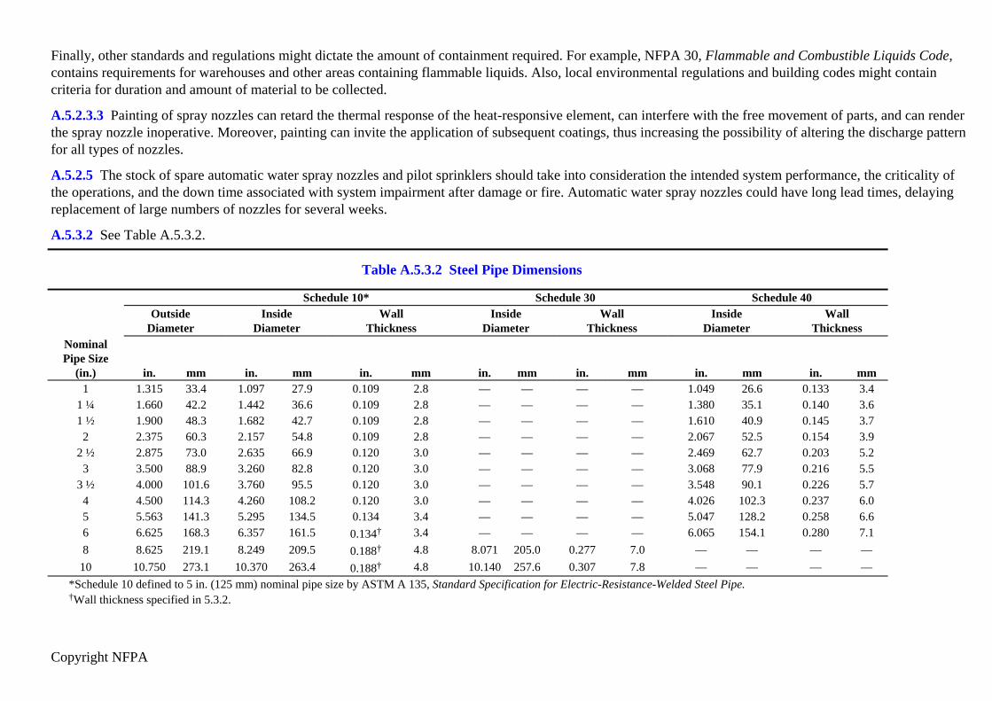
Copyright NFPA
Finally, other standards and regulations might dictate the amount of containment required. For example, NFPA 30, Flammable and Combustible Liquids Code,contains requirements for warehouses and other areas containing flammable liquids. Also, local environmental regulations and building codes might containcriteria for duration and amount of material to be collected.
A.5.2.3.3 Painting of spray nozzles can retard the thermal response of the heat-responsive element, can interfere with the free movement of parts, and can renderthe spray nozzle inoperative. Moreover, painting can invite the application of subsequent coatings, thus increasing the possibility of altering the discharge patternfor all types of nozzles.
A.5.2.5 The stock of spare automatic water spray nozzles and pilot sprinklers should take into consideration the intended system performance, the criticality ofthe operations, and the down time associated with system impairment after damage or fire. Automatic water spray nozzles could have long lead times, delayingreplacement of large numbers of nozzles for several weeks.
A.5.3.2 See Table A.5.3.2.
Table A.5.3.2 Steel Pipe Dimensions
Schedule 10* Schedule 30 Schedule 40 Outside
Diameter Inside
DiameterWall
ThicknessInside
DiameterWall
ThicknessInside
DiameterWall
ThicknessNominalPipe Size
(in.) in. mm in. mm in. mm in. mm in. mm in. mm in. mm1 1.315 33.4 1.097 27.9 0.109 2.8 — — — — 1.049 26.6 0.133 3.4
1 ¼ 1.660 42.2 1.442 36.6 0.109 2.8 — — — — 1.380 35.1 0.140 3.61 ½ 1.900 48.3 1.682 42.7 0.109 2.8 — — — — 1.610 40.9 0.145 3.7
2 2.375 60.3 2.157 54.8 0.109 2.8 — — — — 2.067 52.5 0.154 3.92 ½ 2.875 73.0 2.635 66.9 0.120 3.0 — — — — 2.469 62.7 0.203 5.2
3 3.500 88.9 3.260 82.8 0.120 3.0 — — — — 3.068 77.9 0.216 5.53 ½ 4.000 101.6 3.760 95.5 0.120 3.0 — — — — 3.548 90.1 0.226 5.7
4 4.500 114.3 4.260 108.2 0.120 3.0 — — — — 4.026 102.3 0.237 6.05 5.563 141.3 5.295 134.5 0.134 3.4 — — — — 5.047 128.2 0.258 6.66 6.625 168.3 6.357 161.5 0.134† 3.4 — — — — 6.065 154.1 0.280 7.18 8.625 219.1 8.249 209.5 0.188† 4.8 8.071 205.0 0.277 7.0 — — — —
10 10.750 273.1 10.370 263.4 0.188† 4.8 10.140 257.6 0.307 7.8 — — — —*Schedule 10 defined to 5 in. (125 mm) nominal pipe size by ASTM A 135, Standard Specification for Electric-Resistance-Welded Steel Pipe.†Wall thickness specified in 5.3.2.

Copyright NFPA
A.5.3.5 Other types of pipe and tube that have been investigated and listed for water spray applications include lightweight steel pipe. While these products canoffer advantages, such as ease of handling and installation, cost-effectiveness, and reduction of friction losses, it is important to recognize that they also havelimitations that are to be considered by those contemplating their use or acceptance.
Corrosion studies for lightweight steel pipe have shown that, in comparison to Schedule 40 pipe, its effective life might be reduced, with the level of reductionbeing related to its wall thickness. Further information with respect to corrosion resistance is contained in the individual listings of such products.
The investigation of pipe and tube other than described in Table 5.3.1 should involve consideration of many factors, including the following:
(1) Pressure rating
(2) Beam strength (hangers and spacing)
(3) Unsupported vertical stability
(4) Movement during system operation (affecting water distribution)
(5) Corrosion (internal and external), chemical and electrolytic
(6) Resistance to failure where exposed to elevated temperatures
(7) Methods of joining (strength, permanence, fire hazard)
(8) Physical characteristics related to integrity during earthquakes
(9) Resistance to mechanical and, where applicable, explosion damage
(10) Susceptibility to degradation due to environmental exposure (ultraviolet degradation and low temperatures, etc.)
A.5.4.10 Rubber-gasketed pipe fittings and couplings should not be installed where ambient temperatures can be expected to exceed 150°F (66°C) unless listedfor this service. If the manufacturer further limits a given gasket compound, those recommendations should be followed.
A.5.5.1.2 Some steel piping material having lesser wall thickness than specified in 5.5.1.2 has been listed for use in water spray systems when joined withthreaded connections. The service life of such products can be significantly less than that of Schedule 40 steel pipe, and it should be determined if this servicelife will be sufficient for the application intended.
All such threads should be checked by the installer, using working ring gauges conforming to the Table 8, Basic Dimensions of Ring Gauges for USA(American) Standard Taper Pipe Threads, NPT, in accordance with ANSI/ASME B1.20.1, Pipe Threads, General Purpose, 1983.
A.5.5.2 See Figure A.5.5.2(a) and Figure A.5.5.2(b).

Copyright NFPA
FIGURE A.5.5.2(a) Acceptable Weld Joints.

Copyright NFPA
FIGURE A.5.5.2(b) Unacceptable Weld Joints. [For correct pipe penetration of flange, see Figure A.5.5.2(a).]
A.5.5.2.4.1 Partial penetration welds on outlet fitting connections are considered adequate since there is no significant load on the joint other than that caused by
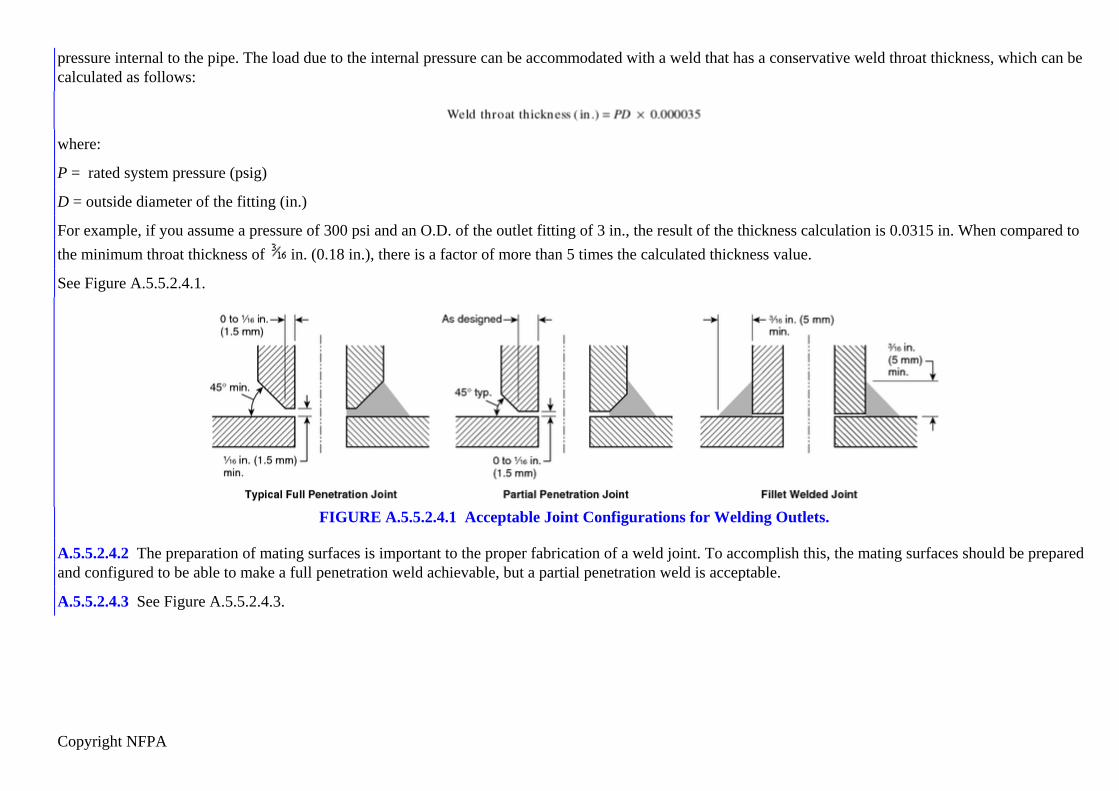
Copyright NFPA
pressure internal to the pipe. The load due to the internal pressure can be accommodated with a weld that has a conservative weld throat thickness, which can becalculated as follows:
where:
P = rated system pressure (psig)
D = outside diameter of the fitting (in.)
For example, if you assume a pressure of 300 psi and an O.D. of the outlet fitting of 3 in., the result of the thickness calculation is 0.0315 in. When compared tothe minimum throat thickness of in. (0.18 in.), there is a factor of more than 5 times the calculated thickness value.
See Figure A.5.5.2.4.1.
FIGURE A.5.5.2.4.1 Acceptable Joint Configurations for Welding Outlets.
A.5.5.2.4.2 The preparation of mating surfaces is important to the proper fabrication of a weld joint. To accomplish this, the mating surfaces should be preparedand configured to be able to make a full penetration weld achievable, but a partial penetration weld is acceptable.
A.5.5.2.4.3 See Figure A.5.5.2.4.3.
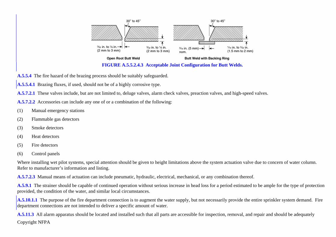
Copyright NFPA
FIGURE A.5.5.2.4.3 Acceptable Joint Configuration for Butt Welds.
A.5.5.4 The fire hazard of the brazing process should be suitably safeguarded.
A.5.5.4.1 Brazing fluxes, if used, should not be of a highly corrosive type.
A.5.7.2.1 These valves include, but are not limited to, deluge valves, alarm check valves, preaction valves, and high-speed valves.
A.5.7.2.2 Accessories can include any one of or a combination of the following:
(1) Manual emergency stations
(2) Flammable gas detectors
(3) Smoke detectors
(4) Heat detectors
(5) Fire detectors
(6) Control panels
Where installing wet pilot systems, special attention should be given to height limitations above the system actuation valve due to concern of water column.Refer to manufacturer’s information and listing.
A.5.7.2.3 Manual means of actuation can include pneumatic, hydraulic, electrical, mechanical, or any combination thereof.
A.5.9.1 The strainer should be capable of continued operation without serious increase in head loss for a period estimated to be ample for the type of protectionprovided, the condition of the water, and similar local circumstances.
A.5.10.1.1 The purpose of the fire department connection is to augment the water supply, but not necessarily provide the entire sprinkler system demand. Firedepartment connections are not intended to deliver a specific amount of water.
A.5.11.3 All alarm apparatus should be located and installed such that all parts are accessible for inspection, removal, and repair and should be adequately

Copyright NFPA
supported.
A.6.1.2 The minimum clearances listed in Table 6.1.2.2 are for the purpose of electrical clearance under normal conditions; they are not intended for use as“safe” distances during fixed water spray system operation.
The clearances are based upon minimum general practices related to design basic insulation level (BIL) values. To coordinate the required clearance with theelectrical design, the design BIL of the equipment being protected should be used as a basis, although this is not material at nominal line voltages of 161 kV orless.
Up to electrical system voltages of 161 kV, the design BIL kV and corresponding minimum clearances, phase to ground, have been established through longusage.
At voltages higher than 161 kV, uniformity in the relationship between design BIL kV and the various electrical system voltages has not been established inpractice. For these higher system voltages, it has become common practice to use BIL levels dependent on the degree of protection that is to be obtained. Forexample, in 230 kV systems, BILs of 1050, 900, 825, 750, and 650 kV have been utilized.
Required clearance to ground can also be affected by switching surge duty, a power system design factor that along with BIL should correlate with selectedminimum clearances. Electrical design engineers might be able to furnish clearances dictated by switching surge duty. Table 6.1.2.2 deals only with clearancesrequired by design BIL. The selected clearance to ground should satisfy the greater of switching surge or BIL duty, rather than being based upon nominalvoltage.
Possible design variations in the clearance required at higher voltages are evident in the table, where a range of BIL values is indicated opposite the variousvoltages in the high voltage portion of the table. However, the clearance between uninsulated energized parts of the electrical system equipment and any portionof the water spray system should not be less than the minimum clearance provided elsewhere for electrical system insulation on any individual component.
A.6.2.1 Water spray systems are usually applied to special fire protection problems beyond the capability of a standard sprinkler system. They are specificallydesigned for fire control, extinguishment, prevention, or exposure protection. These systems typically require that the water be applied rapidly to all protectedsurfaces at the same time, an objective that might not be possible with closed nozzles. In addition, to protect specific surfaces, the use of special nozzles withdirectional discharge is employed. The placement of these nozzles to provide proper coverage is often in conflict with the required placement to ensure promptoperation where automatic nozzles are used. Thus, the standard contemplates that open nozzles will normally be employed and that a separate detection systemwill be used to actuate the system.
There are cases, however, where it is desirable to use closed nozzles to limit the discharge of water to prevent equipment damage (such as when water spray isused to protect turbine bearings), or there are environmental concerns. Automatic nozzles should only be used where open nozzles present such problems and theposition of the nozzles can meet both the coverage and response time design objectives.
A.6.3.2.2.1 See Figure A.6.3.2.2.1.

Copyright NFPA
FIGURE A.6.3.2.2.1 Typical Arrangement of Support Legs for Pipe Stands.
A.6.3.2.2.2 See Figure A.6.3.2.2.2.

Copyright NFPA
FIGURE A.6.3.2.2.2 Sway/Support Brace.
A.6.3.2.2.4 See Figure A.6.3.2.2.4.

Copyright NFPA
FIGURE A.6.3.2.2.4 Support Leg Footings.
A.6.3.2.2.5 See Figure A.6.3.2.2.5(a) through Figure A.6.3.2.2.5(d).

Copyright NFPA
FIGURE A.6.3.2.2.5(a) Typical Pipe Stand Bracket.

Copyright NFPA
FIGURE A.6.3.2.2.5(b) Acceptable Attachment for Pipe to Support Legs — Example 1.

Copyright NFPA
FIGURE A.6.3.2.2.5(c) Acceptable Attachment for Pipe to Support Legs — Example 2.

Copyright NFPA
FIGURE A.6.3.2.2.5(d) Multiple Pipes Supported by One Pipe Stand.
A.6.3.2.6 In cases where the piping cannot be supported by structural members, piping arrangements that are essentially self-supporting are often employedtogether with such hangers as are necessary.
A.6.3.2.7 The performance of piping support systems should allow for expansion and contraction due to temperature change, expansion due to internal waterpressure (thrust), restrained and/or unrestrained joints or pipe runs, heavy point loads (e.g., valves), and pipe deflection (span/support spacing). Manufacturer'sinstallation instructions and engineering design guides should be consulted.
A.6.3.3.6 See Figure A.6.3.3.6.

Copyright NFPA
FIGURE A.6.3.3.6 Drain Connection for System Riser.
A.6.3.6 Areas considered to have an explosion potential can include those having the following characteristics:
(1) Highly exothermic reactions that are relatively difficult to control, such as nitration, oxidation, halogenation, hydrogenation, alkylation, or polymerization
(2) Flammable liquids or gases where a flammable vapor or release of more than 10 tons in a 5-minute time period is possible
(3) Other particularly hazardous operations where an explosion hazard might exist
To limit the potential for explosion damage, the following guidelines should be used:
(1) System actuation valves should be remotely located [at least 50 ft (15.2 m)] from the area to be protected, housed within a blast-resistant valve house orbehind a blast wall designed for at least a gauge pressure of 3 psi (20.7 kPa) static overpressure.
(2) Piping should be located underground wherever possible. Risers should rise aboveground behind a protecting steel column or other structural element.Other piping should be located behind structural elements providing shielding from explosion overpressures and flying debris.
(3) The number of system actuation valves manifolded together should be limited to no more than three.
(4) Fire water mains should be buried, and accessible post indicator isolation valves should be provided.
(5) All water spray piping 2½ in. (65 mm) or larger should be of the welded-flanged type and as shown in Figure A.6.3.6.

Copyright NFPA
FIGURE A.6.3.6 Explosion Protection of Water Spray or Piping (Elevation).
A.6.4.3 Suitable suction provisions can entail the following:
(1) Suitable suction hydrants accessible to apparatus on primary or auxiliary supplies, or both
(2) Suitable all-weather landings or locations where pumper apparatus can take suction at surface water supplies
A.6.4.3.1 Fire department connections should be located and arranged so that hose lines can be readily and conveniently attached without interference fromnearby objects including buildings, fences, posts, or other fire department connections. Where a hydrant is not available, other water supply sources such as anatural body of water, a tank, or a reservoir should be utilized. The water authority should be consulted when a nonpotable water supply is proposed as a suctionsource for the fire department.
See Figure A.6.4.3.1.

Copyright NFPA
FIGURE A.6.4.3.1 Fire Department Connection.
A.6.4.6.1 Care should be taken in the selection of strainers, particularly where nozzle waterways are less than ¼ in. (6.5 mm) in dimension. Considerationshould be given to the size of screen perforation, the volume available for accumulation without excessive friction loss, and the facility for inspection andcleaning.
A.6.5.1.3 Consideration should be given to the protection of the detection system in areas subject to earthquake damage.
A.6.5.2.3 Where detectors are located outdoors or without a ceiling over them to trap the heat, their spacing should be reduced if prompt detection is to beachieved. In general, thermal detectors are to be located within the hot air currents created by the fire if they are to operate. A 50 percent reduction in the spacingbetween detectors is required in the absence of test data on a particular detector and fire size. Some guidance might be available from the manufacturer. Thesensitivity of other detectors (e.g., flammable gas detectors) can also be adversely affected by wind or the lack of walls or ceilings surrounding the hazard.
Heat collectors located above the pilot sprinklers or other thermal detectors for the sole purpose of trapping heat are not recommended. They are consideredprotected canopies (see 6.5.1.2). They can provide some benefit if they are of sufficient size [18 in. × 18 in. (457 mm × 457 mm), or larger] to trap heat. Smallercollectors can reduce sensitivity by causing a “dead” air space. However, shields or canopies needed to protect the detector from the weather should not be

Copyright NFPA
eliminated because of concerns they might reduce detector sensitivity.
Other types of detectors, such as UV detectors that do not rely on air currents to detect a fire or hazardous condition might not require a reduced spacing whenthey are used outdoors.
A.6.5.2.7 Use of flammable gas detectors should consider the following:
(1) Calibration. Automatic flammable gas detection equipment should be calibrated for the specific flammable gas to be detected.
(2) Operation — Alarms. Flammable gas detectors typically are equipped with two independently adjustable alarms for detection of flammable gas. Each unitshould be equipped with a visual indication of alarm points, unit malfunction, and normal operation. Typically, the first alarm point is set between 10percent and 25 percent of the LFL, and the second alarm point trips the water spray system between 25 percent and 65 percent of the LFL. Where theanalyzers alarm in a continuously manned location, remote manual operation of the water spray system from a continuously manned location issometimes utilized with the flammable gas analyzers alarming only in lieu of the automatic trip arrangement.
(3) Inadvertent Activation. A reduction in the potential to inadvertently activate a system can be attained by designing cross-zone activation into the system.With a cross-zone activation scheme, the activation of a water spray system is triggered by the “high” alarm condition of any two or more detectorscomprising the system.
(4) Wiring. Flammable gas detectors should not be wired in series.
(5) Multiple Channel Systems. Where a multiple channel flammable gas detector system is utilized, continuous, instantaneous analysis should be provided onall channels and an alarm or trip should be indicated immediately at the analyzer. No more than one water spray system should be actuated by a singlemultiple channel analyzer.
A.7.1.6 Prompt operation of the water spray system is needed to meet the design objectives. In most installations, the delivery of effective water spray from allopen nozzles should take place within 30 seconds after detection. This can be accomplished by the remote starting of fire pumps. The use of devices such astimers would delay system actuation and negatively affect the system’s intended performance.
A.7.1.10.1 Single systems should be designed to limit flow rates to as small as practicable, with consideration given to the water supplies and other factorsaffecting reliability of the protection. Large system size could decrease system reliability and increase transfer time, water wastage, and environmental impact.Large systems should generally be limited to a discharge rate of 2500 gpm to 3000 gpm (9463 L/min to 11,355 L/min).
A.7.1.10.2 For large areas protected by many adjacent systems, it might not be necessary to base the design flow rate on all systems operating simultaneously.Provided that floor drainage is sloped and sectionalized to reduce the flow of flammables to adjacent areas and assuming that detection systems are carefullydesigned, the maximum design flow rate could be determined by adding the flow rate for any system to the flow rates for all immediately adjacent systems. [Seeexample in Table A.7.1.10.2(a) and Table A.7.1.10.2(b).] The largest sum determined from considering all logical combinations should be used. This maximumanticipated flow rate basis is valid when the systems selected are judged to represent the worst-case situation. Assuming that the above conditions are met, somefires involving several adjacent water spray systems could be adequately controlled with fewer systems operating. Careful engineering judgment should be usedin the determination and calculation of the actuation, capacity, and duration of adjacent water spray systems.

Copyright NFPA
example in Table A.7.1.10.2(a) and Table A.7.1.10.2(b).] The largest sum determined from considering all logical combinations should be used. This maximumanticipated flow rate basis is valid when the systems selected are judged to represent the worst-case situation. Assuming that the above conditions are met, somefires involving several adjacent water spray systems could be adequately controlled with fewer systems operating. Careful engineering judgment should be usedin the determination and calculation of the actuation, capacity, and duration of adjacent water spray systems.
Table A.7.1.10.2(a) Determining Design Flow Rate for Multiple Water Spray Fixed Systems
System 1 System 2 System 3 System 4 System 5 System 6Flow 1800
gpm6813
L/min2100 gpm
7949 L/min
1950 gpm
7381 L/min
2300 gpm
8706 L/min
2400 gpm
9084 L/min
1700 gpm
6435 L/min
Pressure 80 psi 3.8 kPa 95 psi 4.6 kPa 105 psi 5.0 kPa 100 psi 4.8 kPa 90 psi 4.3 kPa 85 psi 4.1 kPaNote: Flow and pressure are required at the point of supply (other common hydraulic point).

Copyright NFPA
Table A.7.1.10.2(b) Determining Design Flow Rate for Combined System, Flow Balanced to Highest Pressure
Flow Flow Flow FlowSystem gpm L/min System gpm L/min System gpm L/min System gpm L/min
1 2062 7805 2 2208 8357 3 1950 7381 4 2300 87062 2208 8357 3 1950 7381 4 2357 8921 5 2530 95763 1950 7381 4 2357 8921 5 2592 9811 6 1844 6979
Total 6220 23,542 Total 6515 24,659 Total 6899 26,113 Total 6674 25,261Notes:(1) The combination of Systems 3, 4, and 5 creates the largest flow at the highest pressure at the point of supply (or other common hydraulic point). Therefore, the designflow rate for this installation is selected as 6899 gpm at 105 psi (26,113 L/min at 5.0 kPa). Total water demand would be 6899 gpm (26,113 L/min), plus an allowance forhose stream application.(2) Systems shall be permitted to be combined in a logical manner such that systems that can be expected to be involved in the same incident and are expected to operatesimultaneously are combined to determine the design flow rate.
A.7.2.1.2 The following are extinguishment methods:
(1) Surface Cooling. Where extinguishment by surface cooling is contemplated, the design provides for complete water spray coverage over the entiresurface. Surface cooling is not effective on gaseous products or flammable liquids and is not generally satisfactory for combustible liquids having flashpoints below 140°F (60°C).
(2) Smothering by Steam Produced. Where this effect is contemplated, the intensity of the expected fire should be sufficient to generate adequate steam fromthe applied water spray, and conditions should be otherwise favorable for the smothering effect. The water spray is to be applied to essentially all theareas of expected fire. This effect should not be contemplated where the material protected could generate oxygen when it is heated.
(3) Emulsification. This effect should be contemplated only for liquids not miscible with water. The water spray should be applied over the entire area offlammable liquids. For those liquids having low viscosities, the coverage should be uniform, and the minimum rate required should be applied with thenozzle pressure not less than the minimum on which approval is based. For more viscous materials, the coverage should be complete but need not be souniform, and the unit rate of application can be lower. A water additive that reduces the surface tension of water can be considered where the effect ofemulsification is contemplated.
(4) Dilution. Where extinguishment by dilution is contemplated, the material should be miscible with water. The application rate should be adequate to effectextinguishment within the required period of time based upon the expected volume of material and the percentage of dilution necessary to render theliquid nonflammable, but not less than that required for control and cooling purposes.
(5) Other Factors. The system design can contemplate other extinguishing factors, such as a continuous film of water over the surface where the material is
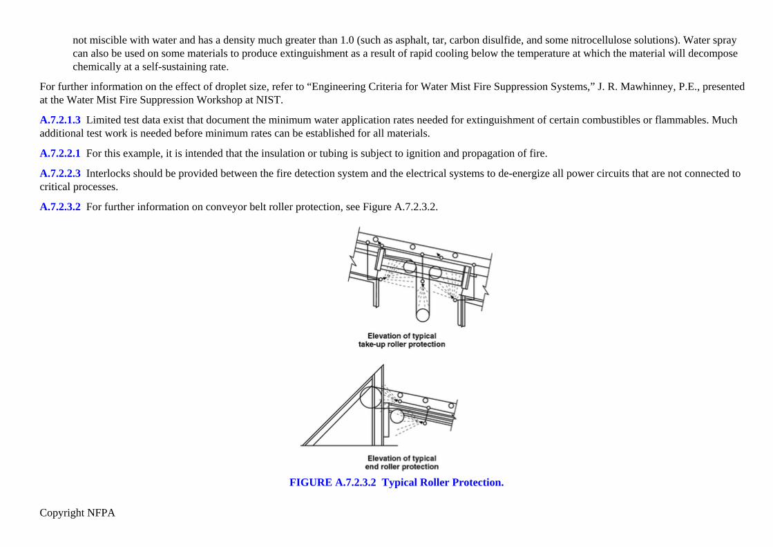
Copyright NFPA
not miscible with water and has a density much greater than 1.0 (such as asphalt, tar, carbon disulfide, and some nitrocellulose solutions). Water spraycan also be used on some materials to produce extinguishment as a result of rapid cooling below the temperature at which the material will decomposechemically at a self-sustaining rate.
For further information on the effect of droplet size, refer to “Engineering Criteria for Water Mist Fire Suppression Systems,” J. R. Mawhinney, P.E., presentedat the Water Mist Fire Suppression Workshop at NIST.
A.7.2.1.3 Limited test data exist that document the minimum water application rates needed for extinguishment of certain combustibles or flammables. Muchadditional test work is needed before minimum rates can be established for all materials.
A.7.2.2.1 For this example, it is intended that the insulation or tubing is subject to ignition and propagation of fire.
A.7.2.2.3 Interlocks should be provided between the fire detection system and the electrical systems to de-energize all power circuits that are not connected tocritical processes.
A.7.2.3.2 For further information on conveyor belt roller protection, see Figure A.7.2.3.2.
FIGURE A.7.2.3.2 Typical Roller Protection.

Copyright NFPA
A.7.2.3.3.1 For further information on typical conveyor belt protection, including return belt, see Figure A.7.2.3.3.1(a) and Figure A.7.2.3.3.1(b).
FIGURE A.7.2.3.3.1(a) Typical Conveyor Belt Protection.

Copyright NFPA
FIGURE A.7.2.3.3.1(b) Typical Hooded Conveyor.
A.7.3.1.1 System operation for a duration of several hours might be necessary before the required activities are completed.
A.7.3.2 Control of burning by directional water spray is not intended to preclude the installation of exposure protection for pump and compressor connections,exposed piping, compressor casings, drivers, lubrication systems, and related equipment.
A.7.4.1 Generally, the upper portions of equipment and the upper levels of supporting structures are less severely exposed by fire than are the lower portions orlevels, due to the accumulation at grade level of fuel from spillage or equipment rupture. Consideration can thus be given to reducing the degree of (oreliminating) water spray protection for the upper portions of high equipment or levels of structures, provided a serious accumulation of fuel or torch action frombroken process piping or equipment cannot occur at these elevations and serious fire exposure does not exist. Examples are certain types of distillation columns[above the 30 ft or 40 ft (9.2 m or 12.2 m)] level and above the third or fourth level of multilevel open structures.
The densities specified for exposure protection include a safety factor of 0.05 gpm/ft2 [2.0 (L/min)/m2] to compensate for unanticipated wastage.
To determine the duration of the exposing fire, consideration should be given to the properties and quantities of the exposing combustibles and the anticipatedeffect of available manual fire fighting. System operation for several hours might be required.
A.7.4.2 It has been established that uninsulated vessels, under average plant conditions, enveloped with flame can be expected to absorb heat at a rate of at least

Copyright NFPA
20,000 Btu/hr/ft2 (63,100 W/m2) of exposed surface wetted by the contents. Unwetted, uninsulated steel equipment absorbs heat rapidly, and failure occurs fromoverpressure or overheating, or both, when such equipment is exposed to fire. Figure A.7.4.2(a) is a time–temperature curve showing the lengths of time requiredfor vessels of different sizes containing volatile materials to have their contents heated to 100°F (38°C) from a starting temperature of 70°F (21°C) for tankcontents and 60°F (16°C) for the tank steel. (See Transactions of the ASME, January, 1944.)
The application of water spray to a vessel enveloped by fire will reduce the heat input rate to a value on the order of 6000 Btu/hr/ft2 (18,930 W/m2) of exposedsurface wetted by the contents where the unit rate of water application is 0.20 gpm/ft2 [8.2 (L/min)/m2] of exposed surface. The 6000 Btu/hr/ft2 (18,930 W/m2)rate was also established in Rubber Reserve Company Memorandum 123. Figure A.7.4.2(b) shows the estimated time for volatile liquid contents of atmosphericstorage tanks to reach the boiling point where absorbing heat at 6000 Btu/hr/ft2 (18,930 W/m2). This value can be compared with Figure A.7.4.2(a) to show thebenefits derived from water spray systems.
FIGURE A.7.4.2(a) Time–Temperature Curve for Vessels Containing Volatile Materials Heated to 100°F (37.8°C).

Copyright NFPA
FIGURE A.7.4.2(b) Time–Temperature Curve for Atmospheric Storage Tank with Volatile Liquid Contents to Reach the Boiling Point.
Where the temperature of a vessel or its contents should be limited, higher densities than specified in 7.4.2.1 might be required.
Internally insulated or lined vessels require special consideration to determine water spray requirements.
A.7.4.2.2 See Figure A.7.4.2.2.

Copyright NFPA

Copyright NFPA
FIGURE A.7.4.2.2 Typical Vertical Tank with Skirt Protection. Refer to 7.4.2.6.
A.7.4.2.3 See Figure A.7.4.2.3.

Copyright NFPA
FIGURE A.7.4.2.3 Typical Horizontal Tank Protection.
A.7.4.3.1 The locations of nozzles should preferably be on alternate sides of the horizontal structural steel.
The wetted surface of a structural member (a beam or column) is defined as one side of the web and the inside surface of one side of the flanges.
A.7.4.3.4 The locations of nozzles should preferably be on alternate sides of the vertical structural steel.
A.7.4.4.1 See Figure A.7.4.4.1.

Copyright NFPA

Copyright NFPA
FIGURE A.7.4.4.1 Typical Transformer Layout.
A.7.5 Water spray systems designed for extinguishment, exposure protection, or control of burning can disperse flammable gases for fire prevention. Whendesigning water spray systems primarily for dispersion of flammable gases (for fire prevention), the following should be considered:
(1) Spray nozzles should be of the size and type to discharge a dense spray into the area of possible flammable vapor release at sufficient velocity to rapidlydilute the flammable vapors to a level below the lower flammable limit.
(2) Spray nozzles should be positioned to provide coverage of potential leak sources such as flanges, flexible connections, pumps, valves, vessels, containers,and so forth.
A.7.6.1 Examples of combined systems include the following:
(1) Open nozzle water spray protection for a vessel combined with area protection provided by a deluge system
(2) Automatic nozzle water spray protection for cable trays combined with area protection provided by a wet pipe system
A.7.6.2 Generally, the water spray component of a combined system is intended to supplement the protection provided by the sprinkler or deluge portion. Thewater spray usually is intended to cover a specific hazard or to cover specific areas or equipment items that cannot be otherwise adequately covered. Therefore,the required density from the sprinkler system should not be reduced when supplemental water spray is provided.
However, it would be acceptable to adjust the extent of water spray coverage when a portion of the coverage is provided by the sprinkler deluge portion of acombined system. For example, pressure vessels within the process structure protected by area deluge are typically provided with supplemental water spray onthe bottom surfaces where the top surfaces are adequately covered by the deluge system above.
A.7.7.1 Different arrangements from those required for other types of detection systems might be required. In particular, it should be remembered that mostlisted detection devices are tested in an indoor, ceiling-mounted environment, while many water spray systems are installed outdoors. This can affect the type ofdetector chosen and its installed spacing.
A.7.7.3 Installations with temperature fluctuations include transformer protection involving heat exchangers having automatic fans and installations involvingindustrial ovens and furnaces. Additionally, protection of machinery involving movement of a hazardous material such as a belt conveyor would require adetection system having a faster response time than normal and appropriate interlocks to stop drive units, as well as other modifications.
A.7.7.4 Though not an aspect that can be designed prior to installation, the response time goal for the detection system is generally 40 seconds from exposure toinitiation of the system actuation valve. The intent of the paragraph is to ensure that artificial delays are not built into the detection (initiating device) system.
A.8.1.1 See Annex B for sample calculations forms.
A.8.1.2 The minimum operating pressure is required for proper pattern development and to overcome the effects of wind. For nozzles with orifices of in. (9.5mm) or less, a minimum pressure of 30 psi (1.4 kPa) is recommended.

Copyright NFPA
A.8.1.4 See Annex B for sample calculations.
A.8.1.5 If then the velocity pressure does not need to be calculated, where v is the velocity (ft/sec) and Pt is the total pressure (psi).
The equation is based on the following calculations:
The starting equation is the basic formula for calculating velocity pressure where flow is in gpm, diameter is in inches, and velocity pressure is in psi.
where:
Pv = pressure, velocity
Q = flow in gpm (L/min)
D = pipe diameter (inside) in inches (mm)
Pt = pressure, total

Copyright NFPA
v = velocity in feet/sec (m/s)
A = cross-sectional area in inches squared (mm2)
The fifth line of the equation corrects the flow to units of cubic feet per second, while the sixth line of the equation corrects the units of feet. The next step is tosubstitute area times velocity for the flow rate, then pi times the diameter squared divided by four for the area. By reducing the numbers and solving for v, thevelocity in the pipe needs to remain at or lower than 2.7 times the square root of the total pressure as proposed.
The velocity is something that many computer models are already solving for, and it is a calculation the user can perform to determine if velocity pressureactually needs to be taken into account prior to doing the velocity pressure.
A.8.3 The standard abbreviations and symbols in Figure B.1(d) should be used.
A.8.3.4 See Figure B.1(c).
A.8.5.1.2 The velocity pressure Pv is determined by trial and error. It is necessary to estimate the flow, Q, in the pipe on the upstream side of the nozzle, whichis used to determine a trial Pv, a trial q, and a trial Q. After determining the trial Q, use this value to determine a new Pv. If the new Pv is approximately equal tothe trial Pv, consider the trial Q to be the actual Q and proceed with calculations. If the Pv does not check with the trial Pv, estimate Q again and proceed withsuccessive corrections until an actual Pv is obtained that checks with a trial Pv.
The velocity pressure Pv is a measure of the energy required to keep the water in a pipe in motion. At the end of the nozzle or end section of a system (whenconsidering the junction of sections of systems) the total pressure available in a pipe at that point should be considered as causing flow. However, at othernozzles or junction points, the pressure causing flow will be the normal pressure, which is the total pressure minus the velocity pressure. Figure A.8.5.1.2(a) andFigure A.8.5.1.2(b) can be used for determining velocity pressures, or velocity pressure can be determined by dividing the flow in gpm squared by the properconstant from Table A.8.5.1.2.

Copyright NFPA
FIGURE A.8.5.1.2(a) U.S. Units. Graph for the Determination of Velocity Pressure.

Copyright NFPA
FIGURE A.8.5.1.2(b) Metric Units. Graph for the Determination of Velocity Pressure.
Table A.8.5.1.2 Constants for Determining Velocity Pressure
Pipe SchedulePipe Size
(in.)Constant Based on
Actual I.D.40 1 1,08040 1¼ 3,230

Copyright NFPA
Table A.8.5.1.2 Constants for Determining Velocity Pressure
Pipe SchedulePipe Size
(in.)Constant Based on
Actual I.D.40 1½ 5,98040 2 16,20040 2½ 33,10040 3 78,80040 3½ 141,00040 4 234,00040 5 577,00040 6 1,204,00030 8 3,780,00040 8 3,620,000
The following assumptions are to be used in applying velocity pressure to the calculations:
(1) At any nozzle along a pipe, except the end nozzle, only the normal pressure can act on a nozzle. At the end nozzle, the total pressure can act.
(2) At any nozzle along a pipe, except the end nozzle, the pressure acting to cause flow from the nozzle is equal to the total pressure minus the velocitypressure on the upstream side.
(3) To find the normal pressure at any nozzle except the end nozzle, assume a flow from the nozzle in question and determine the velocity pressure for thetotal flow on the upstream side. Because the normal pressure is equal to the total pressure minus the velocity pressure, the value of the normal pressure sofound should result in a nozzle flow approximately equal to the assumed flow. If not, a new value should be assumed and the calculations repeated.
Velocity pressure has the effect of reducing the flow from the side outlet of a junction. Ignoring velocity head can introduce a significant error, resulting in anactual nozzle pressure that is less than required. This is especially true where velocities are high (in excess of 20 ft/sec).
The example shown in Figure A.8.5.1.2(b) has been crafted to illustrate situations where a design, if not corrected for an excessive velocity pressure, could yieldresults that underestimate the required flow and pressure for the system.
A.8.5.3 Experience has shown that good results are obtained if the calculations are made in accordance with this section. It is recognized that satisfactory resultscan be obtained by using other methods. However, in order to simplify the checking of calculations and to obtain more consistent correlation between calculatedsystem characteristics and actual system characteristics, it is desirable to use a standard method. The flow from nozzles can be obtained from discharge curvesrather than individual calculations at the preference of the calculator. Similarly, flow characteristics of lines or sections of systems can be obtained by plottingresults on charts made up to N1.85 rather than by calculating constants (K-values).

Copyright NFPA
A.9.3.1 A fire department connection should not be considered as a primary source of water supply for a water spray system.
A.10.1 See NFPA 13, Standard for the Installation of Sprinkler Systems, and NFPA 24, Standard for the Installation of Private Fire Service Mains and TheirAppurtenances, for further information on system acceptance.
A.10.2.1 When planning the flushing operations, consideration should be given to disposal of the water issuing from the test outlets.
A.10.4.2 Some detection circuits might be deliberately desensitized in order to override unusual ambient conditions. In such cases, the response in 10.4.2 mightbe exceeded.
Testing of integrated tubing systems might be related to this test by means of a standard pressure impulse test specified by the listing laboratory.
One method of testing heat detection uses a radiant heat surface at a temperature of 300°F (149°C) and a capacity of 350 W at a distance of 1 in. (25 mm) but notmore than 2 in. (50 mm) from the nearest part of the detector. This method of testing with an electric test set should not be used in hazardous locations. Other testmethods can be employed, but the results should be related to the results obtained under these conditions.
A.10.4.3.2 During the acceptance discharge test, it might be advisable to partially close the system control valve to reduce the system supply pressure to theminimum pressure required by the system calculation. With the gauge at the deluge valve reading the minimum pressure, the test gauges at the most remotenozzle should be read to verify minimum required nozzle pressure. Additionally, pattern and coverage from each open nozzle should be observed to verifyadequate operation.
A.12.1 This standard deals with fixed piped ultra high-speed water spray systems. There are specialized self-contained ultra high-speed deluge systems, whichare outside the scope of this standard. The supervised systems can be used alone or with the ultra high-speed deluge systems discussed in this standard.Nonsupervised systems should not be used without fixed pipe ultra high-speed backup as described in this standard. The following two small self-containeddeluge systems are currently in use [the military ordnance industry (both government and private facilities) is currently the primary user].
(1) The portable deluge system is a transportable self-contained ultra high-speed deluge system. The system uses multiple optical fire detectors, multiplenozzles, and a pressurized water tank [typically 100 gal (379 L) of water]. Response time does not exceed 100 milliseconds (detection to water at thenozzle). The portable system is intended to protect short-term operations. This system is supervised.
(2) A fixed pressurized sphere ultra high-speed deluge system is a self-contained system. The system uses one or more optical fire detectors, at least onepressurized [typically 500 psi (3448 kPa)] water sphere [typically 2.5 gal to 8 gal (10 L to 30 L)] with a rupture disc and internal squib), and an electroniccontroller. Response time is less than 10 milliseconds (detection to water at the nozzle). The sphere discharges water when the squib fires, opening therupture disc. A screen breaks the water into small-atomized particles and collects the residual squib fragments. This system is not currently supervised.
A.12.1.1 Extinguishment of fires using ultra high-speed water spray systems is accomplished by surface cooling, by dispersion or dilution of the combustiblematerial, by cooling the expanding flame front, or by a combination of these factors.
Examples of facilities where such systems are advantageous include rocket fuel manufacturing or processing, solid propellant manufacturing or handling,ammunition manufacturing, pyrotechnics manufacturing, and the manufacture or handling of other volatile solids, chemicals, dusts, or gases. Other facilities

Copyright NFPA
where the very rapid application of water spray is desirable can be considered. Where used to protect process equipment, these systems will not preventoverpressures. This equipment should be protected in accordance with NFPA 68, Guide for Venting of Deflagrations.
A.12.1.2 For the design of deflagration suppression systems for purposes of limiting overpressure, refer to NFPA 69, Standard on Explosion PreventionSystems.
There is no fire protection system that can stop the detonation process when the explosive goes to a high-order state. In many cases, there is a fire or deflagrationbefore the incident progresses to a detonation. An example of high explosives process applications is the extrusion dies for C-4 explosives. In this situation, thereis a high probability that there will be deflagration that can be suppressed with an ultra high-speed water spray system before the transition to a detonation.
A.12.3.1.1 See Figure A.12.3.1.1.
FIGURE A.12.3.1.1 Ultra High-Speed Local Application for a Point of Hazard.
A.12.3.1.2 See Figure A.12.3.1.2.

Copyright NFPA
FIGURE A.12.3.1.2 Ultra High-Speed Area Application for a Small Room.
A.12.3.1.3 An example of a dual application system could be one that protects a specified area from the ceiling and also has nozzles located to protect a specificpoint or points of likely ignition (see Figure A.12.3.1.3).

Copyright NFPA
FIGURE A.12.3.1.3 Ultra High-Speed Dual Application System.
A.12.3.1.4 For additional information, refer to U.S. Department of Defense standard DOD 6055.9-STD, Ammunition and Explosives Safety Standards.
To protect personnel, the process equipment should be interlocked to shut down upon activation of the ultra high-speed water spray system.
A.12.3.2.3 A commonly used density for preventing propagation and structural damage is 0.5 gpm/ft2 [200 (L/min)/m2].
Some hazards, particularly the extinguishment of pyrotechnic fires, require significantly higher density rates. These rates can be as high as 3.0 gpm/ft2 [11(L/min)/m2] for area coverage, or 50 gpm (189 L/min) per nozzle for point protection coverage. Tests have shown that fires involving some pyrotechnicmaterials require a water flow of 200 gpm (757 L/min) or more to extinguish.
A.12.3.4 As speed is a strong function of volumetric capacity, it is recommended that ultra high-speed water spray systems be kept as small as possible. Testshave shown that systems having a capacity in excess of 500 gal (1893 L) are less likely to be capable of delivering water to the nozzles within 100 milliseconds.The capacities of various sizes of pipe are given in Table A.12.3.4 for convenience in calculating system capacity.
Table A.12.3.4 Capacity of One Foot of Pipe (Based on Actual Internal Pipe Diameter)
Gal Gal
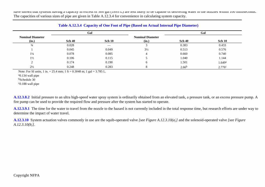
Copyright NFPA
have shown that systems having a capacity in excess of 500 gal (1893 L) are less likely to be capable of delivering water to the nozzles within 100 milliseconds.The capacities of various sizes of pipe are given in Table A.12.3.4 for convenience in calculating system capacity.
Table A.12.3.4 Capacity of One Foot of Pipe (Based on Actual Internal Pipe Diameter)
Gal GalNominal Diameter
(in.) Sch 40 Sch 10Nominal Diameter
(in.) Sch 40 Sch 10¾ 0.028 — 3 0.383 0.4331 0.045 0.049 3½ 0.513 0.576
1¼ 0.078 0.085 4 0.660 0.7401½ 0.106 0.115 5 1.040 1.1442 0.174 0.190 6 1.501 1.649a
2½ 0.248 0.283 8 2.66b 2.776c
Note: For SI units, 1 in. = 25.4 mm; 1 ft = 0.3048 m; 1 gal = 3.785 L.a0.134 wall pipebSchedule 30c0.188 wall pipe
A.12.3.8.2 Initial pressure to an ultra high-speed water spray system is ordinarily obtained from an elevated tank, a pressure tank, or an excess pressure pump. Afire pump can be used to provide the required flow and pressure after the system has started to operate.
A.12.3.9.1 The time for the water to travel from the nozzle to the hazard is not currently included in the total response time, but research efforts are under way todetermine the impact of water travel.
A.12.3.10 System actuation valves commonly in use are the squib-operated valve [see Figure A.12.3.10(a)] and the solenoid-operated valve [see FigureA.12.3.10(b)].

Copyright NFPA
FIGURE A.12.3.10(a) Ultra High-Speed System Using Squib-Actuated Valve.

Copyright NFPA
FIGURE A.12.3.10(b) Ultra High-Speed System Using Solenoid-Operated Valves.
A.12.3.10.1 Consideration should be given to personnel, operations, and maintenance of protected equipment.
A.12.3.11.3 Trapped air in an ultra high-speed water spray system dramatically increases system response time. Piping systems must be sufficiently sloped toallow removal of all trapped air.
A.12.3.12 Pipe movement can be caused by system activation or from the force of a deflagration.
A.12.3.13.1 Strainers minimize sediment from interfering with the proper seating of the poppet.
A.12.4 Response time is commonly measured by placing a waterflow detector on the nozzle and measuring the time from presentation of an energy source to the

Copyright NFPA
sensing device and commencement of water flow at the nozzle.
The following two methods are commonly used to measure response time:
(1) Digital Timer. A millisecond digital timer is started when a saturating energy source is presented to the sensing device and stopped by the actuation of awaterflow switch at the nozzle.
(2) High-Speed Video Recording System. A high-speed video camera and recorder (at least 120 frames/second) can be used to provide a very accuratemeasurement. It can also be used to measure the water travel time from the nozzle to the hazard.
A.12.5.1 A good preventive maintenance program is needed to keep systems operational and reduce false activations. Experience has shown that increasing thetime period beyond 6 weeks results in a significant increase of false activations and other system problems. The following items should be considered whenestablishing maintenance procedures:
(1) System checks.
(a) Measure all voltages.
(b) Put all controllers in bypass, and check for loose wires and/or relays.
(c) Clean all dirt and debris from control panel.
(d) Check all lamps on control panel.
(e) Spot check conduit fittings for moisture and/or loose wire nuts.
(f) Check squib-operated valve o-rings (damp or wet primers).
(g) Check OS&Y valve limit switches on water supply lines.
(2) Sensing devices.
(a) Remove each lens and clean.
(b) Remove each barrel, and check grounding springs, when used.
(c) Tighten each terminal screw in sensing devices.
(d) Clean and inspect all optical integrity rings, when used.
(e) Check for moisture and/or corrosion inside sensing device housings.
(f) Check each detector for proper alignment.
(g) Check housing for continuity.

Copyright NFPA
(h) Reactivate system, and check for problems.
(3) Flow tests should be conducted as follows:
(a) Annually for active systems.
(b) After major maintenance or modification.
(c) After reactivating an inactive system.
(4) Priming water — squib-operated system.
(a) Check weekly.
(b) Open vent.
(c) Crack priming valve.
(d) Allow water to flow for a few minutes, close priming valve, then the vent valve.
(5) Squib-operated valve.
(a) Trip system at least annually by firing primers.
(b) Replace primers at least annually.
(6) Solenoid-operated valves.
(a) Trip system at least annually.
(b) Check solenoid valve for leaks.
Annex B Hydraulic Calculations
This annex is not a part of the requirements of this NFPA document but is included for informational purposes only.
B.1 Forms for Hydraulic Calculations.
See Figure B.1(a) through Figure B.1(d).
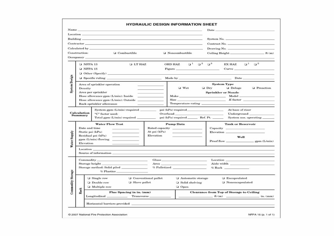
Copyright NFPA

Copyright NFPA
FIGURE B.1(a) Sample Summary Sheet.

Copyright NFPA

Copyright NFPA
FIGURE B.1(b) Sample Worksheet.
FIGURE B.1(c) Sample Graph Sheet.

Copyright NFPA
FIGURE B.1(d) Abbreviations and Symbols for Hydraulic Calculations.
B.2 Sample Calculations.
Figure B.2(a) shows a hypothetical water spray system layout. Figure B.2(e) and Figure B.2(f) show a sample calculation for this system, using pipe sizing andnozzles with constants such that the velocity pressures generally exceed 5 percent of the total pressures, and the designer elected to include velocity pressures.Figure B.2(g) and Figure B.2(h) show a sample calculation for this system, using pipe sizing and nozzles with constants such that velocity pressures are less than5 percent of the total pressures, and the velocity pressures were not included in the calculation. Figure B.2(c) and Figure B.2(d) show a graphical representationof the results of hydraulic calculations shown in Figure B.2(g) and Figure B.2(h), assuming 250 gpm (946 L/min) outside hydrant flow requirements and 4.0 psi(0.28 bar) of underground friction loss.
Calculations for the system in Figure B.2(b) are fairly straightforward until one attempts to balance at junction point “C.” The side outlet of the tee at “C” onlysees the normal pressure. In this example, due to the high velocity through “C”, the normal pressure available to “B” is less than that required to satisfy theindividual nozzle demand. This requires actually increasing the total pressure coming into “C” to satisfy the rule for both velocity head correction and for

Copyright NFPA
pressure balance. If not, the nozzles fed by line “C–B” will be denied adequate flow. [Refer to Figure B.2(b).] The 28.2 psi pressure at “C” from the side outlet isused as a minimum normal pressure starting point, to which the assumed velocity pressure of 13.6 psi is added, to get a new total pressure of 41.8 psi. The flowstraight through the tee at point “C” is then increased by the ratio of (41.8/29.7)1/2.
Figure B.2(i) and Figure B.2(j) present calculations in which velocity pressure is ignored. For the example system shown, correcting the velocity pressureindicates that the system would require 12.1 percent more flow (785.2 gpm vs. 700.5 gpm) and 26.9 percent more pressure (120.2 psi versus 94.7 psi).
The alternatives for correcting the system to a more balanced configuration include increasing the pipe size to reduce the effect of velocity pressure (though thiscan result in an alteration of the specified nozzle’s spray pattern) and modifying the piping arrangement (for example, using bull-headed tees at criticaljunctions). Whether or not a correction is made, the velocity pressure at each side outlet should be examined to determine if corrective action is desired.
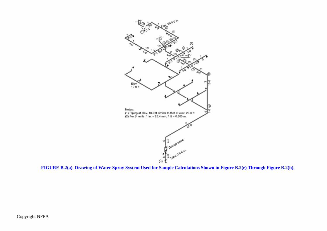
Copyright NFPA
FIGURE B.2(a) Drawing of Water Spray System Used for Sample Calculations Shown in Figure B.2(e) Through Figure B.2(h).

Copyright NFPA
FIGURE B.2(b) Drawing of Water Spray System Used for Sample Calculations Shown in Figure B.2(i) and Figure B.2(j).

Copyright NFPA
FIGURE B.2(c) English. Sample Graph Sheet.
FIGURE B.2(d) Metric. Sample Graph Sheet.

Copyright NFPA

Copyright NFPA
FIGURE B.2(e) English. Calculation of System Shown in Figure B.2(a) with Velocity Pressure Included.

Copyright NFPA

Copyright NFPA
FIGURE B.2(e) Continued

Copyright NFPA

Copyright NFPA
FIGURE B.2(f) Metric. Calculation of System Shown in Figure B.2(a) with Velocity Pressure Included. Nozzle constant = Km = 129.6.

Copyright NFPA

Copyright NFPA
FIGURE B.2(f) Continued

Copyright NFPA

Copyright NFPA
FIGURE B.2(g) English. Calculation of System Shown in Figure B.2(a) with Velocity Pressure Not Included.

Copyright NFPA

Copyright NFPA
FIGURE B.2(g) Continued

Copyright NFPA

Copyright NFPA
FIGURE B.2(h) Metric. Calculation of System Shown in Figure B.2(a) with Velocity Pressure Not Included. Km = 43.2.

Copyright NFPA

Copyright NFPA
FIGURE B.2(h) Continued

Copyright NFPA

Copyright NFPA
FIGURE B.2(i) English. Calculation of System Shown in Figure B.2(b) with Velocity Pressure Included.

Copyright NFPA

Copyright NFPA
FIGURE B.2(j) English. Calculation of System Shown in Figure B.2(b) with Velocity Pressure Not Included.
Annex C Informational References
C.1 Referenced Publications.
The documents or portions thereof listed in this annex are referenced within the informational sections of this standard and are not part of the requirements ofthis document unless also listed in Chapter 2 for other reasons.
C.1.1 NFPA Publications. National Fire Protection Association, 1 Batterymarch Park, Quincy, MA 02169-7471.
NFPA 13, Standard for the Installation of Sprinkler Systems, 2007 edition.
NFPA 14, Standard for the Installation of Standpipe and Hose Systems, 2007 edition.
NFPA 24, Standard for the Installation of Private Fire Service Mains and Their Appurtenances, 2007 edition.
NFPA 30, Flammable and Combustible Liquids Code, 2003 edition..
NFPA 30A, Code for Motor Fuel Dispensing Facilities and Repair Garages, 2007 edition.
NFPA 68, Guide for Venting of Deflagrations, 2002 edition.
NFPA 69, Standard on Explosion Prevention Systems, 2002 edition.
NFPA 251, Standard Methods of Tests of Fire Resistance of Building Construction and Materials, 2006 edition.
NFPA 750, Standard on Water Mist Fire Protection Systems, 2006 edition.
NFPA 1964, Standard for Spray Nozzles, 2003 edition.
Fire Protection Guide to Hazardous Materials, 2001 edition.
C.1.2 Other Publications.
C.1.2.1 ANSI Publications. American National Standards Institute, Inc., 25 West 43rd Street, 4th Floor, New York, NY 10036.
ANSI/ASME B1.20.1, Pipe Threads, General Purpose, 1983.
C.1.2.2 ASME Publications. American Society of Mechanical Engineers, Three Park Avenue, New York, NY 10016-5990.
ASME B.1.20.1, Pipe Threads, General Purpose, 1983.

Copyright NFPA
Transactions of the ASME, January 1944, 1–53. “Requirements for relief of pressure in vessels exposed to fire,” “Venting of tanks exposed to fire,” and “Heatinput to vessels.”
C.1.2.3 ASTM Publications. ASTM International, 100 Barr Harbor Drive, PO. Box C700, West Conshohocken, PA 19428-2959.
ASTM A 135, Standard Specification for Electric-Resistance-Welded Steel Pipe, 1993.
C.1.2.4 NIST Publications. National Institute of Standards and Technology, 100 Bureau Drive, Stop 1070, Gaithersburg, MD 20899-1070.
Mawhinney, J. R. 1993. “Engineering Criteria for Water Mist Fire Suppression Systems.” Presented at Water Mist Fire Suppression Workshop, March 1–2.
C.1.2.5 National Technical Information Service Publications. 5285 Port Royal Road, Springfield, VA 22161.
U.S. Department of Defense Standard DOD 6055.9-STD, Ammunition and Explosives Safety Standards.
C.1.2.6 Other Publications.
Department of the Army, Ammunition and Explosives Safety Standards, Headquarters Department of the Army, Washington D.C. Pamphlet 385-64, 28November 1997.
Sprinkler Hydraulics and What It’s All About, Harold S. Wass, Jr., Society of Fire Protection Engineers, April 2000.
Rubber Reserve Company Memorandum 123, “Protection of Vessels Exposed to Fire.”
C.2 Informational References.
The following documents or portions thereof are listed here as informational resources only. They are not a part of the requirements of this document.
Requirements for Relief of Overpressure in Vessels Exposed to Fire, J. J. Duggan, C. H. Gilmour, P. F. Fisher.
Rubber Reserve Company Memorandum 89, November 19, 1944, “Heat Input to Vessels.”
C.3 References for Extracts in Informational Sections. (Reserved)