Principle of Structural Restoration for Hagia
10
Principle of Structural Restoration for Hagia Sophia Dome T. Aoki\ S. Kato^. K. Ishikawa^ K. Hidaka\ M. Yorulmaz^ &F. CiliS ^School of Design and Architecture, Nagoya City University, Chikusa, Nagoya 464- Japan EMail: aoki@sda. nagoya-cu. ac.jp ^Department of Architecture and Civil Engineering, Toyohashi University, Fukui 910. Japan EMail: [email protected] Taksim, Istanbul 80191. Turkey EMail: [email protected] Abstract The present study includes 1) measurements of natural frequencies by ambient vibrations, 2) estimation of the Young's modulus for the used materials based on dynamic measurements for the domes and minarets, and 3) finite element three dimensional elasto-plastic analysis (FEM) in both cases of dead and earthquake loads, for the dome considering the effects of the supporting structure. The discussions on structural behaviors lead a principle for structural restoration for Hagia Sophia. Transactions on the Built Environment vol 26, © 1997 WIT Press, www.witpress.com, ISSN 1743-3509
Transcript of Principle of Structural Restoration for Hagia

Principle of Structural Restoration for HagiaSophia Dome
T. Aoki\ S. Kato^. K. Ishikawa K. Hidaka\ M. Yorulmaz^
&F. CiliS
^School of Design and Architecture, Nagoya City University,
Chikusa, Nagoya 464- Japan
EMail: aoki@sda. nagoya-cu. ac.jp
^Department of Architecture and Civil Engineering, Toyohashi
University, Fukui 910. Japan
EMail: [email protected]
Taksim, Istanbul 80191. Turkey
EMail: [email protected]
Abstract
The present study includes 1) measurements of natural frequencies by ambientvibrations, 2) estimation of the Young's modulus for the used materials based ondynamic measurements for the domes and minarets, and 3) finite element threedimensional elasto-plastic analysis (FEM) in both cases of dead and earthquakeloads, for the dome considering the effects of the supporting structure. Thediscussions on structural behaviors lead a principle for structural restoration forHagia Sophia.
Transactions on the Built Environment vol 26, © 1997 WIT Press, www.witpress.com, ISSN 1743-3509

468 Structural Studies, Repairs and Maintenance of Historical Buildings
1 Introduction
Our present work is a part of the surveying project of Hagia Sophia whichhag been conducted from 1990 to 1997 as a joint research between Japaneseand Turkish scholars. The structural survey of our project have been par-tially published as the following four parts, i.e.. 1) investigation of crackpattern[l], 2) measurements of natural frequencies by ambient vibrations[2.3], 3) estimation of the Young's modulus for the used materials based ondynamic measurements for the domes and minarets[3. 4], and 4) FEM threedimensional elasto-plastic analysis, in both cases of dead and earthquakeloads to the comprehensive structural system including the dome and thesupporting structures [5. 6].
In this paper, based on the above investigation, the structural weak-ness of the whole structure for Hagia Sophia was estimated and a possiblestructural system for its rehabilitation is presented.
2 Estimation of the Young's Modulus
2.1 Analytical Model
We have prepared two types of analytical models: one is composed of 9-nodeisoparametric Heterosis shell elements and the other is composed of 20-nodeisoparametric solid elements (Figure 1). The analytical models correspondto one half of the actual structure. The boundary condition at the baseof the minarets is assumed to be fixed and their rocking behaviors are nottaken into account. As the stiffness of the wooden roof of the minarets
(a)brick (b)stone (c)stone (d)stone (e)stonesouth-east south-west north-east south-east north-west
Hagia Sophia Siileymaniye MosqueFigure 1: Fundamental frequencies (Hz) and spectra based on the measure-ment of micro tremors and analytical models with first natural mode fromeigenvalue analysis.
Transactions on the Built Environment vol 26, © 1997 WIT Press, www.witpress.com, ISSN 1743-3509
Structural Studies, Repairs and Maintenance of Historical Buildings 469
is lower than the stiffness of brick and stone, the stiffness of the roof wasignored and only their weights were taken into consideration.
From the experience of Prof. Yorulmaz[7]. the bulk density of the brickand the stone used in the finite element analysis are assumed to be 1.72//nfand 2.0fy/77?3, respectively. Each total numbers for nodes and elements inthese models are given in Table 1.
Table 1: Total number of nodes and Table 2: Results of the eigenvalueelements in the models. analysis.
node
element
20-node9-node20-node9-node
HaB-SE4192254848
gia SophiaS-SW4192254848
S-NE4192254848
SiilevmaniveS-SE5182796060
S-NW4192254848
Frequency (Hz)E(xlO*kgf/cnr)
20-node9-node
Hagia SophiaB-SE1.002.812.79
S-SW1.256.136.06
S-NE1.007.357.26
SiileymaniyeS-SE0.877.487.47
S-NW1.126.126.11
2.2 Young's moduli of the brick and the stone
The results of the eigenvalue analysis are shown graphically in Figure 1 andTable 2. showing the global configurations for the original and deformedminarets as their first natural mode.
From comparing the fundamental frequency observed in micro tremorswith the result obtained through numerical eigenvalue analysis, the Young'smoduli of the brick and the stone used for those minarets are estimated2.8 x lO^y/cm^ and 6.8 x lO^p/ycnf. respectively. That is. the Young'smoduli of the brick and the stone used for those minarets are about 1/7.5and 1/3.1 of the Young's modulus of concrete of 2.1 x
3 Three dimensional FEM elasto-plastic analysis
3.1 Analytical Model
Structural characteristics of the dome are investigated through materialand geometrical non-linear analyses. The three dimensional elasto-plasticanalysis is applied to the comprehensive structural system including thedome and supporting structures [5] . The analytical models correspond toone quarter and one half of the actual structure, respectively, dependingon the loading cases of dead and dead plus earthquake load. Two typesof analytical models are prepared using 9-node Heterosis shell elements:Model A and B (Figures 5 and 7). Difference is found in the treatment ofthe lowest part of the dome where the dome is ringed by the buttress-likepiers. Model A comprises double rows of shell elements in this part, the innerrow corresponding to the domical shell and the outer row corresponding tothe projection of the buttress-like piers. In Model B. the entire thick wall ofthe lowest part is represented by a single row of elements with transitional
Transactions on the Built Environment vol 26, © 1997 WIT Press, www.witpress.com, ISSN 1743-3509
470 Structural Studies, Repairs and Maintenance of Historical Buildings
trapezoidal elements over them. As for the lower supporting structure.Model A comprises the main pier, the buttress pier, the secondary pier,the semidome with the barrel vault on its narrowed end, the transversalarch, the double arch framing the tympanum, the pendentive and the dome(Figure 5). Model B is more inclusive, comprising furthermore the outerwall of the aisle, the gallery roof, the tympanum, the exedra. the wall closingthe nave from the narthex and the square dome base covering back side thependentive on the back side (Figure 7). Total numbers of elements andnodes in these two models are given in Table 3.
The shell element consists of eight layers, the yielding condition of whichis given in Figure 2. Figures 3 and 4 show the stress-strain relationship ofconcrete characterizing the element. Strain hardening of the material afterthe ultimate strength is ignored, though a small amount of tension stiffeningis assumed for the sake of the expediency to achieve numerical efficiency.1/2 Young's Modulus of concrete is assumed here and material constantsused in the analysis are listed in Table 4.
3.2 Results of the analysis
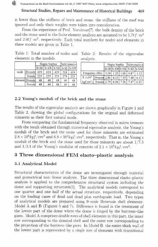
The results of the analysis in case of dead load are shown graphically inFigures 5 to 9. The global configurations in Model A and B are shown inFigures 5 and 7 for the original and deformed dome. The circle delineatedby the base of the dome deforms into an ellipse in both these cases. Themassive double arches on the north and the south sides deflect outwarddue to the thrust of the dome. On the eastern and the western sides,however, the upper parts of the great semidomes deflect inward due to therigidity discontinuity at the north-south great arches, while the main domeproducing the outward thrust. This oval displacement pattern of the baseof the dome is in accordance with the actual state of the structure. Onthe narrowed end of the semidome. the thrust pushes down the edge ofthe adjacent barrel vault, which again qualitatively tallies with what wasrecorded by Van Nice [8].
Admittedly, the main piers and buttresses are deformed owing to thethrust exerted by the upper structure. According to our result, the directionof the deformation deviates slightly southward (or northward) from thediagonal of the central square defined by the four piers. This tendency makesus suppose that the magnitude of the component of the thrust transmittedthrough the western (or eastern) transverse arch and the adjacent area ofthe pendentive is greater than the other component given primarily by thedouble arches. In this respect. Prof. Mark has provided the specific data[9].The east-west reaction at the top of the main pier is reported to be 540£/and north-south reaction to be 400f/. The qualitative result of our analysisis not opposing to these values.
Displacements of and around the pier are smaller in Model B than ModelA. The rigidity of the structure and the weight of the semi-cubic dome-base
Transactions on the Built Environment vol 26, © 1997 WIT Press, www.witpress.com, ISSN 1743-3509

Structural Studies, Repairs and Maintenance of Historical Buildings 471
over the pendentive surely contribute to lessen the relating displacementsin Model B.
Figure 2: Yielding condition applied Figure 3: Stress-strain relationshipin the analysis for concrete const it u- for concrete constitutive model.tive model.
Table 4: Material constants used inthe finite element analvsis.
Young's modulusPoisson's ratioWeight per unit volume
domelower structure
Ultimate strengthtensih
compressmUltimate compressive strainTension stiffening parameter
E = 1At = 1
y = 17 = 2
ft'-f/ = 2£ u=0« m=0a =0
.OxlO'kefcrrr6
.7tfm-
.Otf nr
2kgf cnrOOkefcm-.003.002.5
Figure 4: Loading and unloading be-havior of cracked concrete for tensionstiffening.
Table 3: Total number of nodes andelements in the models.
Modelnode
element
A-Q1244220
B-Q2462491
A-NS2447440
A-EW2448440
B-NS4865982
B-EW4837982
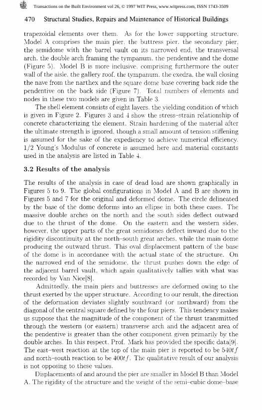
The relationship between the vertical load parameter A and the dis-placements at various locations in Model A and B are plotted in Figure9. Comparison of the displacements of two transverse arches seems to giveinformation that the north to south arch is weaker than the west to eastarch. This structural property is congruent with the analytical fact that thecollapse mode of the analyzed structure is due to the failure by happeninga mechanism at the middle height of the north to south arch. On the otherhand, the horizontal displacement at the junction of the two big arches atopthe main pier in the present Model B is not so large and reversible with thereduction of loading parameter. Thus, together with the progressive behav-ior of the arch located at the junction between the central dome and thesemi dome, the main reason of the global collapse of the structure may beattributed to the failure of the north to south arch.
Transactions on the Built Environment vol 26, © 1997 WIT Press, www.witpress.com, ISSN 1743-3509
472 Structural Studies, Repairs and Maintenance of Historical Buildings
Figure 5: Deformation of the struc- Figure 6: Crack of the structureture at maximum vertical load state at maximum vertical load state inin Model A-Q. Model A-Q.
Figure 7: Deformation of the struc- Figure 8: Crack of the structureture at maximum vertical load state at maximum vertical load state inin Model B-Q. Model B-Q.
Model A-
-(mm).-60 -40 - 20 0
Vertical displacementat the apex of the dome
j5 2o>roS 1
I ' I rModel A-
-80 -40 0Vertical displacementat the N- S arch top
0 40 80Horizontal displacement
at double arch topFigure 9: Relationship between vertical load parameter A and displacementsat various points in the structure in Model A and B.
Transactions on the Built Environment vol 26, © 1997 WIT Press, www.witpress.com, ISSN 1743-3509
Structural Studies, Repairs and Maintenance of Historical Buildings 473
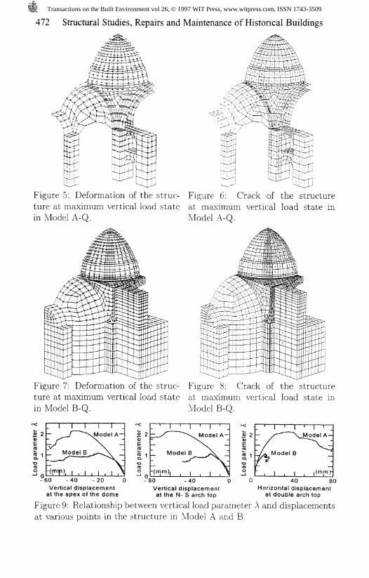
Figure 10: Deformation of the struc- Figure 11: Crack of the structure atture at maximum horizontal N-S maximum horizontal N-S load stateload state in Model A-XS. in Model A-NS.
Figure 12: Deformation of the struc- Figure 13: Crack of the structure atture at maximum horizontal N-S maximum horizontal N-S load stateload state in Model B-NS. in Model B-NS.
0.2
I I IModel A
-60 -40 -20Vertical displacementat the apex of the dome
Model B -f I , | , |(mm)L
-40 -20Vertical displacementat the N- S arch top
0 20 40Horizontal displacement
at double arch top
Figure 14: Relationship between horizontal N-S load parameter A and dis-placements at various points in the structure in Model A and B.
Transactions on the Built Environment vol 26, © 1997 WIT Press, www.witpress.com, ISSN 1743-3509

474 Structural Studies, Repairs and Maintenance of Historical Buildings
Figure 15: Deformation of the struc- Figure 16: Crack of the structure atture at maximum horizontal E-W maximum horizontal E-W load stateload state in Model A-EW. in Model A-EW.
Figure 17: Deformation of the struc- Figure 18: Crack of the structure atture at maximum horizontal E-W maximum horizontal E-W load stateload state in Model B-EW. in Model B-EW.
0.2
0-01
IQ.2
0.1
-60 -40 -20 0Vertical displacementat the apex of the dome
-100 -50 0Vertical displacementat the N- S arch top
-40 -20 0Horizontal displacement
at double arch topFigure 19: Relationship between horizontal E-W load parameter A anddisplacements at various points in the structure in Model A and B.
Transactions on the Built Environment vol 26, © 1997 WIT Press, www.witpress.com, ISSN 1743-3509
Structural Studies, Repairs and Maintenance of Historical Buildings 475
The results of the analysis in case of dead plus earthquake loads areshown graphically in Figures 10 to 19. The global configurations in Model Aand B are shown in Figures 10, 12, 15 and 17 for the original and deformeddome. The relationship between the horizontal load parameter A and thedisplacements at various locations in Model A and B are plotted in Figures14 and 19. There is no difference between the tendency of the displace-ments between dead and dead plus earthquake loads. This phenomenonsuggests that the main reason of the global collapse of the structure maybe attributed to the failure of the north to south arch.
According to the allowable stress design in Turkey, the design baseshear coefficient for important masonry buildings is 0.18. The dome ofHagia Sophia seems to be safe in both horizontal directions against theearthquake with about 80 gals, where dynamic amplification is assumed 2.5times.
4 Conclusion
Though the actual deformation is too large to be analyzed in the elasto-plastic phase of the material, our results correspond well to the oval de-formation observed along the base of the dome. The above investigationhas concluded that the structural weakness of the whole structures exist inthe east and west arches combined with the two adjacent half domes. Thisconclusion leads to the structural policy that this weakness exists still underthe dead loads and will appear surely apw-agou distinctly under earthquakes innear future, and that the west and east great arches, the two half domes andthe adjacent supporting structures have to be structurally repaired followedby a proposal for a possible structural system for rehabilitation.
Acknowledgement
The authors wish to express gratitudes to the Ministry of Education, Sci-ence, Sports and Culture (Monbusho International Scientific Research Pro-gram: Field Research) and Daikou Scholarship Foundation for financialsupports.
References
1. T. Aoki, S. Kato & K. Hidaka, Crack Pattern in Hagia Sophia Domeand its Comparison with those from Analysis. Proceedings of theIASS-CSCE International Symposium, Toronto, Canada. Vol.1, pp.730-741. 1992.
2. T. Aoki, S. Kato & K. Ishikawa, Structural Characteristics of theDome of Hagia Sophia from Measurement of Micro Tremor, Proceed-ings of the STREMA International Symposium, Bath, UK, pp.115-122. 1993.
Transactions on the Built Environment vol 26, © 1997 WIT Press, www.witpress.com, ISSN 1743-3509

476 Structural Studies, Repairs and Maintenance of Historical Buildings
3. T. Aoki, S. Kato, K. Ishikawa, M. Yorulmaz & F. C ili,o
o?% Mms^reme/z^ o/ A/zero Tremors, Journal of StructuralEngineering, Tokyo, Japan, Vol.40B, pp.87-98, 1994.
4. T. Aoki, S. Kato. K. Ishikawa, M. Yorulmaz & F. Qili,
on Measurement of Micro Tremors. Proceedings of theIASS International Symposium, Milan. Italy. Vol.2, pp.1135-1142,1995.
5. S. Kato, T. Aoki, K. Hidaka & H. Nakamura, Finite-Element Mod-eling of the First and Second Domes of Hagia Sophia, Hagia SophiaFrom the Age of Justinian to the Present, Cambridge University Press.pp.103-119, 1992.
6. T. Aoki, S. Kato, K. Ishikawa & K. Hidaka, Deformation and SeismicStrength of the Dome of Hagia Sophia, Journal of Structural Engi-neering, Tokyo, Japan, Vol.43B, pp.641-646, 1997.
7. M. Yorulmaz, Anastylosis of the Apollo Temple in Side/Antalya. Turkey,Proceedings of the STREMA International Symposium, Florence. Italy,pp.447-456, 1989.
8. L. Van Nice. 51 5bp&m m MomW - /Im ArcM2ecZ%W wruei/, Wash-ington, 1st installment 1965, 2nd installment due 1986. (The funda-mental record of the present state of the structure).
9. R. Mark, Z/zpK l W. 6Yr%cf%re, MIT Press, 1990.
Transactions on the Built Environment vol 26, © 1997 WIT Press, www.witpress.com, ISSN 1743-3509