
PRINCE WILLIAM COUNTY VINT HILL RD. EXTENSION
287
PRINCE WILLIAM COUNTY VINT HILL RD. EXTENSION PWC Project No. SPR2018-00040 INVITATION FOR BID NO. IFB7029107 Prince William County post notices of amendment/addenda to a solicitation on the County’s e-procurement website at: www.pwcgov.org/eservices/eprocurement. All Bidders must verify or confirm issuance of addenda prior to submitting a bid. Notice to all Bidders: In the event of inclement weather and Prince William County implements its liberal leave policy the due date for receipt of bids is postponed until such time as extended by subsequent written addenda. BID DUE DATE: July 26, 2018 NO LATER THAN 3:00 P.M. LOCAL TIME (unless changed by formal written addenda) DELIVER SEALED BID TO: PRINCE WILLIAM COUNTY PURCHASING McCOART ADMINISTRATION SHANA N. TERRY, SR. CONTRACT SPECIALIST 1 COUNTY COMPLEX COURT, SUITE 205 PRINCE WILLIAM, VA 22192-9201 Direct written technical questions to Owner Representative: Mark Gunn P.E, Project Manager, Rinker Design Associates, P.C. (703) 368-7373, or email at: [email protected] with subject line “VINT HILL RD. EXTENSION” with a copy to Shana N. Terry at [email protected]. General and Informational Questions Contact: Shana N. Terry, Senior Contract Specialist at 703-792-7233, or email at: [email protected] with subject line “VINT HILL RD. EXTENSION”. Advertisement Date: June 22, 2018
Transcript of PRINCE WILLIAM COUNTY VINT HILL RD. EXTENSION

PRINCE WILLIAM COUNTY VINT HILL RD. EXTENSION
PWC Project No. SPR2018-00040
INVITATION FOR BID NO. IFB7029107
Prince William County post notices of amendment/addenda to a solicitation on the County’s e-procurement website at: www.pwcgov.org/eservices/eprocurement. All Bidders must verify or confirm issuance of addenda prior to submitting a bid.
Notice to all Bidders: In the event of inclement weather and Prince William County implements its liberal leave policy the due date for receipt of bids is postponed until such time as extended by subsequent written addenda.
BID DUE DATE: July 26, 2018 NO LATER THAN 3:00 P.M. LOCAL TIME (unless changed by formal written addenda)
DELIVER SEALED BID TO: PRINCE WILLIAM COUNTY PURCHASING McCOART ADMINISTRATION SHANA N. TERRY, SR. CONTRACT SPECIALIST 1 COUNTY COMPLEX COURT, SUITE 205 PRINCE WILLIAM, VA 22192-9201
Direct written technical questions to Owner Representative: Mark Gunn P.E, Project Manager, Rinker Design Associates, P.C. (703) 368-7373, or email at: [email protected] with subject line “VINT HILL RD. EXTENSION” with a copy to Shana N. Terry at [email protected].
General and Informational Questions Contact: Shana N. Terry, Senior Contract Specialist at 703-792-7233, or email at: [email protected] with subject line “VINT HILL RD. EXTENSION”.
Advertisement Date: June 22, 2018

VINT HILL RD. EXTENSION Table of Contents TOC-1
PRINCE WILLIAM COUNTY VINT HILL RD. EXTENSION
PWC Project No. SPR2018-00040
TABLE OF CONTENTS
MISCELLANEOUS DOCUMENTS
Cover Page
Table of Contents
BIDDING DOCUMENTS
Invitation I-1
*Proposal Form P-1
*Summary/Schedule of Unit Prices S-1
*Bid Bond BB-1
Insurance Checklist INS CK-1
Conditions of the Contract
County Supplemental Specifications to SS-1 VDOT Road and Bridge Specifications
County Contract Special Provisions CSP-1
City of Manassas Waterline Special Provisions CSP-2
Contract (Sample) C-1
VDOT Special Provisions, Supplemental Specifications, VSP-1 and Special Provision Copied Notes
Contract Requirements
*Bidder Certification of Prequalification BC-1 Classification and Work Capacity
Contractor’s Request for Payment RP-2
Change Order CO-1
Change Order Directive CD-1

VINT HILL RD. EXTENSION Table of Contents TOC-2
Performance Bond PB-1
Labor and Materials Payment Bond LM-1
Affidavit, Waiver of Lien and Release of Contractor, WL-1 Subcontractor, or Supplier
Contractor’s Proposal to Sublet/Source of Supplies CS-1
Escrow Agreement EA-1
Appendices
APPENDIX A – Geotechnical Engineering Report.
APPENDIX B – Environmental Permits
END OF TABLE OF CONTENTS

VINT HILL RD. EXTENSION I-1 of 2 Invitation for Bid
PRINCE WILLIAM COUNTY VINT HILL RD. EXTENSION
INVITATION FOR BID NO. IFB7029107 PWC Project No. SPR2018-00040
Unless changed by formal written addenda, sealed bids for VINT HILL RD. EXTENSION construction project will be received until 3:00 P.M., July 26, 2018, in the Prince William County McCoart Administration, Purchasing Office, Suite 205, 1 County Complex Court, Prince William, Virginia 22192-9201, (703) 792-6770 (located off of the Prince William Parkway, Woodbridge, Virginia). Bids received after the time specified will not be accepted.
Generally, the Project includes construction of the widening of Vint Hill Road (Rte. 215) from 0.1 miles west of Sudley Manor Drive (Rte. 1566) to 0.3 miles east of Gary Glen Drive (Rte. 3100) with a project length of 0.3 miles. The project will also include widening along Kettle Run Road from Vint Hill Road to Patriot High School (approximately 0.1 miles). This segment of Route 215 is classified as an Urban Collector Street System (GS-7) with a design speed of 45 mph. Major project features include: 1) roadway widening and reconstruction, 2) storm drainage improvements, 3) major culvert construction, 4) stormwater management facilities, 5) large water main construction and utility relocations, and 6) traffic signal reconstructions.
Work includes, but is not limited to, the installation of erosion control devices, clearing and grubbing, grading, excavation, installing storm sewers pipes and drainage structures, culvert installation, stormwater management facilities, curb and gutter, placing aggregate, asphalt paving, pedestrian facilities (sidewalk/shared use path), installation of traffic signage and pavement markings, fencing, waterline and sanitary sewer construction, traffic signal, and all measures required for the maintenance of traffic during construction. All work shall be performed in accordance with the approved project plans and bid documents. The completed project shall meet any and all requirements for final acceptance by the Virginia Department of Transportation.
Interested Contractors may become a registered Plan Holder by purchasing a CD ROM of printable all inclusive Bidding/Contract Documents, Specs and Plans (drawings and specs) for non-refundable amount of $60.00 from the County’s consulting engineer at: Rinker Design Associates, P.C., 9385 Discovery Boulevard, Suite 200, Manassas, VA 20109, Attention: Mark Gunn PE, (703) 368-7373. Checks shall be made payable to Rinker Design Associates, P.C.
Registered Plan Holders may make copies for purpose of directly bidding the project but are not permitted to re-sell, copy, or re-distribute printed plans and specs or the CD ROM. Bids will not be accepted from any firm who is not registered as a Plan Holder (Purchaser of the Plans and Bidding Documents).
Bidders are advised that notice of Addenda to this project are publicized on Prince William County e-procurement website. Bidders shall attest to receipt of addenda prior to submitting a bid.
If Specifications, Plans, a word, phrase, clause, or any other portion of the Invitation For Bid including the Bid Pricing Proposal or other documents which makeup the Contract Documents, is alleged to be ambiguous/confusing or in conflict, the Bidder shall submit written notice of such to the Engineer: Mark Gunn, P.E., [email protected] with a copy to Shana N. Terry,

VINT HILL RD. EXTENSION I-2 of 2 Invitation for Bid
[email protected] no later than seven (10) days prior to the date for receipt of Bids and shall request an interpretation. The County shall not be responsible for any other explanations or interpretations of the Bidding Documents or Contract Documents unless made by formal Addenda. No employee or agent of the County shall have the authority to furnish any other explanation or interpretation, verbal or written.
All Bidders shall have a valid certificate of authority or registration to transact business in Virginia with the Virginia State Corporation Commission as required by Title 13.1 or Title 50 of the Code of Virginia at time of bid submission. Prior to submission of bids, all Bidders shall be VDOT prequalified.
In accordance with Prince William County Purchasing Regulations, the County reserves the right to reject any bids, waive informalities and irregularities in bidding, and to accept bids, which are, in consideration, in the best interest of the County.
Bidders interested in bidding shall have registered with Prince William County Purchasing e-Procurement, a 24 hour access for vendor registration, including a variety of solicitation, contract and general information at: www.pwcgov.org/eservices/eprocurement .
END OF SECTION

VINT HILL RD. EXTENSION P-1 of 3 Proposal Form
PRINCE WILLIAM COUNTY VINT HILL RD. EXTENSION
INVITATION FOR BID NO. IFB7029107PWC Project No. SPR2018-00040
PROPOSAL PRICING FORM I. DECLARATION:
COMPANY NAME OF BIDDER: ______________________________________________
I/We, the undersigned have examined the location of the proposed work, declare: no other person, firm or corporation has interest in this Proposal; carefully examined any/all documents pertaining to the Contract thoroughly and understand the contents thereof; that Plans, Standard Specifications, Supplemental Specifications, Special Provisions, Addenda, and all other documents form a part of this Proposal as if set forth fully herein.
I/We, the undersigned, understand that the attached Summary of Prices are incorporated by reference and made a part hereto and any quantities of work as shown unless designated as plan quantity are estimated by the Engineer and are approximate only and may be greater or less, and offer to do the work, based on this estimate of quantities, at the UNIT prices stated on the Summary of Prices, unless such quantities change as a result of authorized changes by the Engineer or the County; in which case the compensation will increase or decrease at the Unit Price times the quantities of the item of work performed. The Summary or Schedule of Prices shall be good for a period of at least one hundred twenty (120) days after date set for receipt of bids unless this period is extended by the Bidder.
I/We, the undersigned, declare as full compensation for the satisfactory prosecution of the project, the Total Cost which is to be determined by multiplying the actual in place quantities (except for noted plan quantities) by the appropriate unit prices as set forth in the agreement. The Contract Total Bid amount is set forth:
______________________________________________________________________________(In Words)
Dollars ($___________________________________) which is determined by multiplying the appropriate estimated quantities by the appropriate unit prices as set forth in the Summary/Schedule of Unit Prices contained herein.

VINT HILL RD. EXTENSION P-2 of 3 Proposal Form
II. ACKNOWLEDGEMENTS AND CERTIFICATIONS: The undersigned Bidderacknowledges and certifies:
FIRST: To begin Work within fifteen calendar days from date of Contract award by the Board of County Supervisors unless otherwise indicated in the written “Notice to Proceed” prosecute the Work in such a manner as to achieve to Final Completion by August 31, 2019 for any and all Work, including Punch-list Work, other contractual requirements set by the Contract.
SECOND: Bidder acknowledges receipt of Addenda Number ______of ____ and also acknowledges Bid submitted reflects all such Amendment/Addenda and any/all changes/revisions to Contract Documents inclusive of specifications/plan sheets.
THIRD: The Bidder (check/circle one) WILL / WILL NOT adopt the Escrow Provision specified in Supplementary Specification. Failure to indicate will be construed Bidder will not adopt the Escrow Provision.
FOURTH: The Bidder agrees and understands Liquidated Damages are set in accordance with 2016 VDOT Road Bridge Specifications Section 108.6(b) Liquidated Damages on this project for each day beyond 12 months of the Notice to Proceed, in which the work including punch-list items, all submittals and all other contractual requirements whatsoever under this project remain incomplete.
III. BID REPRESENTATION AND EXECUTION:
I/We, represent in preparation and submission of this Bid, I/we did not, either directly or indirectly, enter into any combination or arrangement with any person, firm or corporation or enter into any agreement, participate in any collusion, or otherwise take any action in restraint of free, competitive bidding in violation of the Sherman Act (15 U.S.C. Section 1 et seq) or Sections 59.1-9.1 through 59.1-9.17 or Sections 59.1-68.6 through 59.1-68.8 of the Code of Virginia, 1950 as amended, and is as such a violation of the State and Federal law and can result in fines, prison sentences, and civil damage awards.
I/We, hereby declare and certify that the responses to the above representations, certifications-actions, and other statements are accurate and complete and meet the requirements of Title 54.1, Chapter 11, of the Code of Virginia, pertaining to regulations and registrations of construction contractors.
I/We declare as a vendor transacting business with Prince William County shall have a valid certificate of authority from or register with the State Corporation Commission (SCC), as required by Title 13.1 or Title 50 of the Code of Virginia and shall maintain such authority or registration to transact business in the Commonwealth during the term of any resulting contract.
I/We, agree to abide by all conditions of the Contract for which I/We are bidding and certify that I/We are authorized to sign this bid on behalf of the Bidder and declare below under penalty of perjury of the laws of the United States.

VINT HILL RD. EXTENSION P-3 of 3 Proposal Form
Bidder is (Check one): Individual ( ) Partnership ( ) Corporation ( )
Residence of Bidder:
(if individual)
Name of Partners:
(if partnership)
State of Incorporation: (if corporation)
Organized under the laws of the State of __________________________________
Name and Street Address of Registered Agent or person authorized to accept service of process on behalf of the entity ___________________________________________________________
Street Address of Principal place of business _______________________________________
Attach to this form the names and addresses of all persons having an ownership interest of 3% or more in the Company:
SIGNATURE: By:
(Typed/Printed Name of Bidder) Authorized Representative
Title:
Date of Bid:
Phone Number: _________________________Fax: __________________________
Electronic (E-Mail): ______________________________________
Virginia Contractor Registration No. _________________ Expiration: _____________
PWC Vendor Registration No.
State Corporation Commission (SCC) Licensing Registration No.____________________, as required by Title 13.1 or Title 50 of the Code of ___________________

VINT HILL RD. EXTENSION SCHEDULE OF UNIT PRICES
IFB No. IFB7029107
ITEMVDOT ITEM
CODESPEC DESCRIPTION UNIT
ESTIMATED QUANTITY
UNIT PRICE EXTENDED PRICE
1 513 513 MOBILIZATION LS 1 $ ‐ $ ‐
2 517 517 CONSTRUCTION SURVEYING LS 1 $ ‐ $ ‐
3 301 301 CLEARING & GRUBBING LS 1 $ ‐ $ ‐
4 303 303 REGULAR EXCAVATION CY 8,463 $ ‐ $ ‐
5 303 303 BORROW EXCAVATION CY 12,475 $ ‐ $ ‐
6 303 303 UNDERCUT EXCAVATION ‐ CONTINGENT CY 2,054 $ ‐ $ ‐
7 514 514 FIELD OFFICE TYPE I MO 12 $ ‐ $ ‐
8 10013 307 CEMENT STABILIZED AGGREGATE MATERIAL NO. 21A TON 665 $ ‐ $ ‐
9 10103 308 309 CR. RUN AGGR. MATL. NO. 25 OR 26 TON 101 $ ‐ $ ‐
10 10128 305 AGGREGATE BASE MATL.TY.1 NO. 21B TON 6,283 $ ‐ $ ‐
11 10610 315 ASPHALT CONCRETE TY. IM‐19.0A TON 2,438 $ ‐ $ ‐
12 10636 315 ASPHALT CONCRETE TY. SM‐9.5A TON 834 $ ‐ $ ‐
13 10636 315 ASPHALT CONCRETE TY. SM‐9.5D TON 2,074 $ ‐ $ ‐
14 10642 315 ASPHALT CONCRETE TY. BM‐25.0A TON 4,724 $ ‐ $ ‐
15 10417 315 TACK COAT GAL 40 $ ‐ $ ‐
16 16110 315 ASPHALT SLURRY SEAL TYPE A SY 397 $ ‐ $ ‐
17 02090 501 NS PIPE (EX. PIPE TO BE CLEANED) LF 641 $ ‐ $ ‐
18 10628 515 FLEXIBLE PAVEMENT PLANING (TWO 1‐INCH PASSES) SY 27,427 $ ‐ $ ‐
GENERAL ITEMS
PAVEMENT ITEMS
INCIDENTAL ITEMS
Page 1 OF 14

VINT HILL RD. EXTENSION SCHEDULE OF UNIT PRICES
IFB No. IFB7029107
ITEMVDOT ITEM
CODESPEC DESCRIPTION UNIT
ESTIMATED QUANTITY
UNIT PRICE EXTENDED PRICE
19 11070 315 NS SAW‐CUT ASPH. CONC. FULL DEPTH LF 6,551 $ ‐ $ ‐
20 11070 316 NS SAW CUT ASPH. CONC. LF 114 $ ‐ $ ‐
21 12030 502 STD. CURB CG‐3 LF 570 $ ‐ $ ‐
22 12032 502 RADIAL CURB CG‐3 LF 86 $ ‐ $ ‐
23 12600 502 STD.COMB.CURB & GUTTER CG‐6 LF 4,094 $ ‐ $ ‐
24 12610 502 RAD.COMB.CURB & GUTTER CG‐6 LF 720 $ ‐ $ ‐
25 12700 502 STD.COMB.CURB & GUTTER CG‐7 LF 278 $ ‐ $ ‐
26 12710 502 RAD.COMB.CURB & GUTTER CG‐7 LF 74 $ ‐ $ ‐
27 12920 502 ENTRANCE GUTTER CG‐9D SY 212 $ ‐ $ ‐
28 13108 105,502 CG‐12 DETECTABLE WARNING SURFACE SY 23 $ ‐ $ ‐
29 13212 503 R/W MONUMENT RM‐2 EA 53 $ ‐ $ ‐
30 13220 502 HYDR.CEMENT CONC.SIDEWALK AND CURB RAMP 4" SY 2,024 $ ‐ $ ‐
31 13281 221,505 GUARDRAIL MGS1A LF 160 $ ‐ $ ‐
32 NS PLAN MOD. BGR‐01 BOX CULVERT GUARDRAIL LF 25 $ ‐ $ ‐
33 13286 221,505 GUARDRAIL MGS2 EA 2 $ ‐ $ ‐
34 14440 502 SAW CUT SIDEWALK LF 22 $ ‐ $ ‐
35 14450 502 SAW CUT CURB AND GUTTER LF 14 $ ‐ $ ‐
36 21020 502 MEDIAN STRIP MS‐1 SY 63 $ ‐ $ ‐
37 21110 502 MEDIAN STRIP MS‐1A SY 192 $ ‐ $ ‐
38 21215 502 MEDIAN STRIP MS‐2 LF 831 $ ‐ $ ‐
39 22643 507 FENCE FE‐CL LF 350 $ ‐ $ ‐
Page 2 OF 14

VINT HILL RD. EXTENSION SCHEDULE OF UNIT PRICES
IFB No. IFB7029107
ITEMVDOT ITEM
CODESPEC DESCRIPTION UNIT
ESTIMATED QUANTITY
UNIT PRICE EXTENDED PRICE
40 22677 507 FE‐CL DOUBLE GATE L=14' EA 1 $ ‐ $ ‐
41 24410 508 DEMOLITION OF PAVEMENT SY 6,538 $ ‐ $ ‐
42 24502 510 NS REMOVE EXISTING PIPE LF 331 $ ‐ $ ‐
43 24502 510 NS REMOVE EXISTING STRUCTURE & TOP EA 1 $ ‐ $ ‐
44 24502 510 NS REMOVE EXISTING ENDWALL EA 5 $ ‐ $ ‐
45 00211 303 MINOR STR. EXCAV. PIPE CULVERT CY 223 $ ‐ $ ‐
46 00212 303 MINOR STR. EXCAV. BOX CULVERT CY 46 $ ‐ $ ‐
47 00522 302 CONCRETE CLASS A4 BOX CULVERT CY 43 $ ‐ $ ‐
48 00525 302 CONCRETE CLASS A3 MISC. CY 19 $ ‐ $ ‐
49 00540 302 406 REINF. STEEL (BOX CULVERT) LB 4,880 $ ‐ $ ‐
50 00585 501 UNDERDRAIN UD‐2 (PERFORATED) LF 589 $ ‐ $ ‐
51 00588 501 UNDERDRAIN UD‐4 (PERFORATED) LF 5,900 $ ‐ $ ‐
52 00588 501 UNDERDRAIN UD‐4 (NON PERFORATED) LF 321 $ ‐ $ ‐
53 00595 501 OUTLET PIPE LF 164 $ ‐ $ ‐
54 00596 302 EW‐12 END WALL (4:1) EA 3 $ ‐ $ ‐
55 01150 302 15" PIPE LF 171 $ ‐ $ ‐
56 01152 302 15" CONC. PIPE LF 10 $ ‐ $ ‐
57 01156 302 STORM SEWER PIPE 15" LF 2,413 $ ‐ $ ‐
58 01180 302 18" CONC. PIPE LF 33 $ ‐ $ ‐
59 01186 302 STORM SEWER PIPE 18" LF 202 $ ‐ $ ‐
DRAINAGE ITEMS
Page 3 OF 14

VINT HILL RD. EXTENSION SCHEDULE OF UNIT PRICES
IFB No. IFB7029107
ITEMVDOT ITEM
CODESPEC DESCRIPTION UNIT
ESTIMATED QUANTITY
UNIT PRICE EXTENDED PRICE
60 01200 302 18" GASKETED STORM SEWER PIPE LF 38 $ ‐ $ ‐
61 01200 302 CONCRETE CRADLE LF 38 $ ‐ $ ‐
62 01242 302 24" REINF. CONC. PIPE LF 27 $ ‐ $ ‐
63 01246 302 STORM SEWER PIPE 24" LF 321 $ ‐ $ ‐
64 01480 302 48" PIPE LF 125 $ ‐ $ ‐
65 06150 302 15" END SECTION ES‐1 EA 16 $ ‐ $ ‐
66 06180 302 18" END SECTION ES‐1 EA 3 $ ‐ $ ‐
67 06240 302 24" END SECTION ES‐1 EA 1 $ ‐ $ ‐
68 06240 602 MOD. EW‐1 END WALL EA 1 $ ‐ $ ‐
69 06495 302 48" EW‐2 END WALL EA 2 $ ‐ $ ‐
70 006495 302 EW‐6S END WALL EA 1 $ ‐ $ ‐
71 06745 302 DROP INLET DI‐2A EA 1 $ ‐ $ ‐
72 06815 302 DROP INLET DI‐3A EA 3 $ ‐ $ ‐
73 06816 302 DROP INLET DI‐3AA EA 1 $ ‐ $ ‐
74 06817 302 DROP INLET DI‐3B, L=4' EA 5 $ ‐ $ ‐
75 06818 302 DROP INLET DI‐3B, L=6' EA 10 $ ‐ $ ‐
76 06819 302 DROP INLET DI‐3B, L=8' EA 4 $ ‐ $ ‐
77 06820 302 DROP INLET DI‐3B, L=10' EA 3 $ ‐ $ ‐
78 06835 302 DROP INLET DI‐3C, L=6' EA 2 $ ‐ $ ‐
79 07506 302 DROP INLET DI‐5 (TYPE III GRATE) EA 2 $ ‐ $ ‐
80 08990 302 ST'D MONOLITHIC BOX EA 2 $ ‐ $ ‐
Page 4 OF 14

VINT HILL RD. EXTENSION SCHEDULE OF UNIT PRICES
IFB No. IFB7029107
ITEMVDOT ITEM
CODESPEC DESCRIPTION UNIT
ESTIMATED QUANTITY
UNIT PRICE EXTENDED PRICE
81 08990 302 ST'D B‐2 DOGHOUSE W/ FOOTING BASE EA 1 $ ‐ $ ‐
82 09056 302 MANHOLE MH‐1 OR 2 LF 1.3 $ ‐ $ ‐
83 09057 302 FRAME & COVER MH‐1 EA 1 $ ‐ $ ‐
84 09148 414 EROS. CONTR. STONE CL.A1, TYPE A EC‐1 TON 261 $ ‐ $ ‐
85 09148 414 EROS. CONTR. STONE CL.1, TYPE B EC‐1 TON 284 $ ‐ $ ‐
86 10100 309 AGGREGATE MATERIAL NO. 21B TON 49 $ ‐ $ ‐
87 22643 507 FENCE FE‐CL LF 348 $ ‐ $ ‐
88 22653 507 LINE BRACE UNIT FE‐CL EA 1 $ ‐ $ ‐
89 22663 507 CORNER BRACE UNIT FE‐CL EA 4 $ ‐ $ ‐
90 22677 507 GATE FE‐CL L=14' EA 1 $ ‐ $ ‐
91 24831 510 NS ADJUST EXIST DROP INLET EA 2 $ ‐ $ ‐
92 27326 303 SOIL STAB.MAT.EC‐3 TYPE B SY 835 $ ‐ $ ‐
93 27500 303 GEOTEXTILE FABRIC SY 57 $ ‐ $ ‐
94 27545 302 STORM WATER MANAGEMENT BASIN EXCAVATION CY 1,848 $ ‐ $ ‐
95 27550 302 STORM WATER MANAGEMENT DRAINAGE STRUCT. SWM‐1 LF 6.5 $ ‐ $ ‐
96 27552 303 NS NO. 57 STONE TON 38 $ ‐ $ ‐
97 23560 512 TEMPORARY SAFETY FENCE 4' LF 349 $ ‐ $ ‐
98 27288 303 EROSION CONTROL MULCH ACRE 5 $ ‐ $ ‐
99 27345 303 TEMPORARY DIVERSION DIKE LF 470 $ ‐ $ ‐
100 27415 303 CHECK DAM(ROCK) TY. II EA 65 $ ‐ $ ‐
EROSION & SEDIMENT CONTROL ITEMS
Page 5 OF 14

VINT HILL RD. EXTENSION SCHEDULE OF UNIT PRICES
IFB No. IFB7029107
ITEMVDOT ITEM
CODESPEC DESCRIPTION UNIT
ESTIMATED QUANTITY
UNIT PRICE EXTENDED PRICE
101 27422 303 DEWATERING BASIN EC‐8 EA 2 $ ‐ $ ‐
102 27430 303 SILTATION CONTROL EXCAVATION CY 1,799 $ ‐ $ ‐
103 27451 303 INLET PROTECTION TYPE A EA 4 $ ‐ $ ‐
104 27461 303 INLET PROTECTION TYPE B EA 39 $ ‐ $ ‐
105 27505 303 TEMP. SILT FENCE LF 7,789 $ ‐ $ ‐
106 27012 602 TOPSOIL CLASS A 2" ACRE 2.9 $ ‐ $ ‐
107 27101 603 TEMPORARY SEEDING LB 290 $ ‐ $ ‐
108 27102 603 REGULAR SEEDING LB 435 $ ‐ $ ‐
109 27103 603 OVERSEEDING LB 348 $ ‐ $ ‐
110 27104 603 LEGUME SEED LB 19 $ ‐ $ ‐
111 27105 603 LEGUME OVERSEEDING LB 15 $ ‐ $ ‐
112 27230 603 FERTILIZER (NITROGEN ‐ N) LB 278 $ ‐ $ ‐
113 27231 603 FERTILIZER (PHOSPHORUS ‐ P) LB 381 $ ‐ $ ‐
114 27232 603 FERTILIZER (POTASSIUM ‐ K) LB 191 $ ‐ $ ‐
115 27250 603 LIME TON 14 $ ‐ $ ‐
116 27112 603 HYDRAULIC EROSION CONTROL PRODUCT TYPE 2 SY 17,545 $ ‐ $ ‐
117 27112 603 HYDRAULIC EROSION CONTROL PRODUCT TYPE 3 SY 14,036 $ ‐ $ ‐
118 ATTD 303 TMP EARTHWORK (SEE CONTRACT SP) LS 1 $ ‐ $ ‐
119 13604 512 PLAN IMPACT ATTEN.SER.TY.I (TL‐3,> 45 MPH) EA 2 $ ‐ $ ‐
ROADSIDE DEVELOPMENT
TRANSPORTATION MANAGEMENT PLAN/SEQUENCE OF CONSTRUCTION ITEMS
Page 6 OF 14

VINT HILL RD. EXTENSION SCHEDULE OF UNIT PRICES
IFB No. IFB7029107
ITEMVDOT ITEM
CODESPEC DESCRIPTION UNIT
ESTIMATED QUANTITY
UNIT PRICE EXTENDED PRICE
120 23560 512 TEMPORARY SAFETY FENCE 4' LF 9,000 $ ‐ $ ‐
121 24100 511 ALLAYING DUST HR 650 $ ‐ $ ‐
122 24150 512 TYPE III BARRICADE, 4' EA 4 $ ‐ $ ‐
123 24152 512 TMP ‐ TYPE III BARRICADE, 8' EA 27 $ ‐ $ ‐
124 24160 512 CONSTRUCTION SIGNS SF 2,500 $ ‐ $ ‐
125 24272 512 TRUCK MOUNTED ATTENUATOR HR 2,000 $ ‐ $ ‐
126 24278 512 GROUP 2 CHANNELIZING DEVICES DAY 45,000 $ ‐ $ ‐
127 24279 512 PORTABLE CHANGEABLE MESSAGE SIGN HR 4,500 $ ‐ $ ‐
128 24281 512 ELECTRONIC ARROW HR 2,500 $ ‐ $ ‐
129 24282 512 FLAGGER SERVICE HR 4,000 $ ‐ $ ‐
130 24297 512 TRAFFIC BARRIER SERVICE CONC.DOUBLE FACE LF 900 $ ‐ $ ‐
131 51955 512, ATTDTEMPORARY TRAFFIC CONTROL SIGNAL (VINT HILL RD & SUDLEY MANOR DRIVE) (SEE CONTRACT SP)
LS 1 $ ‐ $ ‐
132 51955 512, ATTDTEMPORARY TRAFFIC CONTROL SIGNAL(VINT HILL ROAD & KETTLE RUN ROAD) (SEE CONTRACT SP)
LS 1 $ ‐ $ ‐
133 54105 512 ERADICATION OF EXIST. PAVE.MARKING (LINEAR) LF 15,000 $ ‐ $ ‐
134 54106 512 ERADICATION OF EXIST. PAVE.MARKING (NONLINEAR) SF 420 $ ‐ $ ‐
135 54217 512 TEMP. PAVE. MARKER. 1 WAY EA 45 $ ‐ $ ‐
136 54217 512 TEMP. PAVE. MARKER. 2 WAY EA 15 $ ‐ $ ‐
137 54424 512 CONSTRUCTION PAVEMENT MARKING TYPE D ELONG.ARROW EA 10 $ ‐ $ ‐
138 54510 512 CONSTRUCTION PAVEMENT MARKING (TY.D, CI.I) 4" LF 12,000 $ ‐ $ ‐
139 54522 512 CONSTRUCTION PAVEMENT MARKING (TY.D, CI.I) 24" LF 420 $ ‐ $ ‐
140 80082 512, ATTDIMPLEMENTATIONS OF TMP/SOC DETOUR (SHEETS 1L(4)‐1L(5)) ‐ VINT HILL ROAD CLOSURE
LS 1 $ ‐ $ ‐
Page 7 OF 14
VINT HILL RD. EXTENSION SCHEDULE OF UNIT PRICES
IFB No. IFB7029107
ITEMVDOT ITEM
CODESPEC DESCRIPTION UNIT
ESTIMATED QUANTITY
UNIT PRICE EXTENDED PRICE
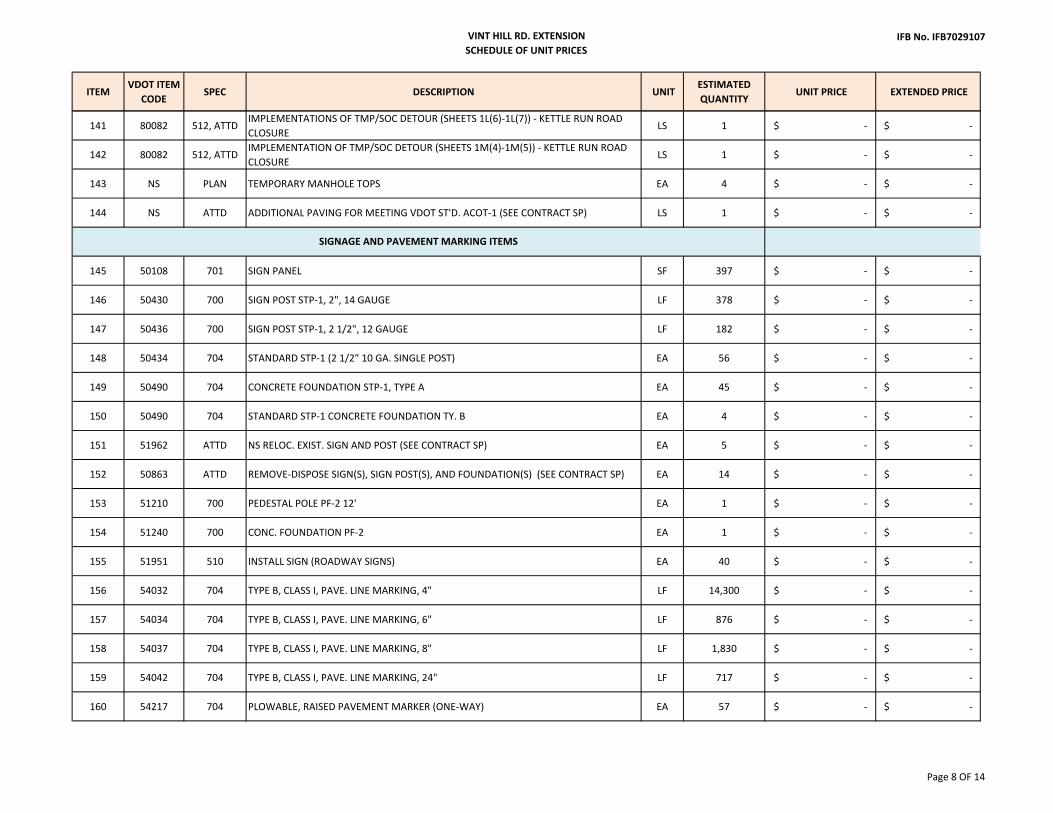
141 80082 512, ATTDIMPLEMENTATIONS OF TMP/SOC DETOUR (SHEETS 1L(6)‐1L(7)) ‐ KETTLE RUN ROAD CLOSURE
LS 1 $ ‐ $ ‐
142 80082 512, ATTDIMPLEMENTATION OF TMP/SOC DETOUR (SHEETS 1M(4)‐1M(5)) ‐ KETTLE RUN ROAD CLOSURE
LS 1 $ ‐ $ ‐
143 NS PLAN TEMPORARY MANHOLE TOPS EA 4 $ ‐ $ ‐
144 NS ATTD ADDITIONAL PAVING FOR MEETING VDOT ST'D. ACOT‐1 (SEE CONTRACT SP) LS 1 $ ‐ $ ‐
145 50108 701 SIGN PANEL SF 397 $ ‐ $ ‐
146 50430 700 SIGN POST STP‐1, 2", 14 GAUGE LF 378 $ ‐ $ ‐
147 50436 700 SIGN POST STP‐1, 2 1/2", 12 GAUGE LF 182 $ ‐ $ ‐
148 50434 704 STANDARD STP‐1 (2 1/2" 10 GA. SINGLE POST) EA 56 $ ‐ $ ‐
149 50490 704 CONCRETE FOUNDATION STP‐1, TYPE A EA 45 $ ‐ $ ‐
150 50490 704 STANDARD STP‐1 CONCRETE FOUNDATION TY. B EA 4 $ ‐ $ ‐
151 51962 ATTD NS RELOC. EXIST. SIGN AND POST (SEE CONTRACT SP) EA 5 $ ‐ $ ‐
152 50863 ATTD REMOVE‐DISPOSE SIGN(S), SIGN POST(S), AND FOUNDATION(S) (SEE CONTRACT SP) EA 14 $ ‐ $ ‐
153 51210 700 PEDESTAL POLE PF‐2 12' EA 1 $ ‐ $ ‐
154 51240 700 CONC. FOUNDATION PF‐2 EA 1 $ ‐ $ ‐
155 51951 510 INSTALL SIGN (ROADWAY SIGNS) EA 40 $ ‐ $ ‐
156 54032 704 TYPE B, CLASS I, PAVE. LINE MARKING, 4" LF 14,300 $ ‐ $ ‐
157 54034 704 TYPE B, CLASS I, PAVE. LINE MARKING, 6" LF 876 $ ‐ $ ‐
158 54037 704 TYPE B, CLASS I, PAVE. LINE MARKING, 8" LF 1,830 $ ‐ $ ‐
159 54042 704 TYPE B, CLASS I, PAVE. LINE MARKING, 24" LF 717 $ ‐ $ ‐
160 54217 704 PLOWABLE, RAISED PAVEMENT MARKER (ONE‐WAY) EA 57 $ ‐ $ ‐
SIGNAGE AND PAVEMENT MARKING ITEMS
Page 8 OF 14

VINT HILL RD. EXTENSION SCHEDULE OF UNIT PRICES
IFB No. IFB7029107
ITEMVDOT ITEM
CODESPEC DESCRIPTION UNIT
ESTIMATED QUANTITY
UNIT PRICE EXTENDED PRICE
161 54217 704 PLOWABLE, RAISED PAVEMENT MARKER (TWO‐WAY) EA 16 $ ‐ $ ‐
162 54300 704 PAVEMENT MESSAGE MARK. ELONGATED ARROW SINGLE EA 27 $ ‐ $ ‐
163 54400 704 PAVEMENT MESSAGE MARK. "ONLY" EA 11 $ ‐ $ ‐
164 NS ATTD NS ELECTRICAL SERVICE/COMM CONNECTION TO SCHOOL FLASHER SIGN(SEE CONTRACT SP) LS 1 $ ‐ $ ‐
165 50108 701 SIGN PANEL (FOR SIGNAL) SF 166 $ ‐ $ ‐
166 51030 PLAN NS CONTROLLER EA 1 $ ‐ $ ‐
167 51137 510 INSTALL CONTROLLER EA 1 $ ‐ $ ‐
168 51961 PLAN NS MODIFY CONTROLLER EA 1 $ ‐ $ ‐
169 51160 700 ELEC. SERV. GROUNDING ELECTRODE 10' EA 7 $ ‐ $ ‐
170 51170 700 ELECTRICAL SERVICE SE‐5 EA 1 $ ‐ $ ‐
171 51184 703 TRAFFIC SIGNAL HEAD SECTION 12" LED EA 54 $ ‐ $ ‐
172 51198 703 PEDESTRIAN ACTUATION PA‐2 EA 8 $ ‐ $ ‐
173 51212 700 PF‐2 PEDESTAL POLE 12' EA 8 $ ‐ $ ‐
174 51238 700 CONCRETE FOUNDATION SIGNAL POLE PF‐8 CY 40 $ ‐ $ ‐
175 51240 700 CONCRETE FOUNDATION SIGNAL POLE PF‐2 EA 11 $ ‐ $ ‐
176 51247 700 CONCRETE FOUNDATION CF‐3 EA 1 $ ‐ $ ‐
177 51248 700 PF‐2 PEDESTAL POLE 5' (FOR SE‐5) EA 1 $ ‐ $ ‐
178 51425 700 NS SIGNAL POLE (ST'D MP‐3 POLE) EA 3 $ ‐ $ ‐
179 51426 700 NS MAST ARM (49' ARM FOR ST'D. MP‐3) EA 1 $ ‐ $ ‐
180 51426 700 NS MAST ARM (75' ARM FOR ST'D. MP‐3) EA 1 $ ‐ $ ‐
TRAFFIC SIGNALIZATION ITEMS
Page 9 OF 14

VINT HILL RD. EXTENSION SCHEDULE OF UNIT PRICES
IFB No. IFB7029107
ITEMVDOT ITEM
CODESPEC DESCRIPTION UNIT
ESTIMATED QUANTITY
UNIT PRICE EXTENDED PRICE
181 51426 700 NS MAST ARM (78' ARM FOR ST'D. MP‐3) EA 1 $ ‐ $ ‐
182 51540 703 LOOP DETECTOR AMPLIFIER EA 15 $ ‐ $ ‐
183 51600 700 14/2 CONDUCTOR CABLE LF 1,935 $ ‐ $ ‐
184 51600 700 14/2 SHIELDED CONDUCTOR CABLE LF 4,225 $ ‐ $ ‐
185 51607 700 14/7 CONDUCTOR CABLE LF 6,275 $ ‐ $ ‐
186 51615 700 14/1 ENCLOSED COND. CABLE LF 2,720 $ ‐ $ ‐
187 51830 703 HANGER ASSEMBLY SM‐3 ONE WAY (IN LINE) EA 75 $ ‐ $ ‐
188 51830 703 HANGER ASSEMBLY SM‐3 ONE WAY (CLUSTER) EA 1 $ ‐ $ ‐
189 51840 703 NS HANGER ASSEMBLY SMD‐2 (FOR SIGNAL SIGNS) EA 27 $ ‐ $ ‐
190 51951 510 INSTALL SIGN (FOR SIGNAL) EA 19 $ ‐ $ ‐
191 51963 ATTD NS REMOVE EX. SIGNAL EQUIPMENT (PER INTERSECTION) (SEE CONTRACT SP) LS 2 $ ‐ $ ‐
192 51963 703 SAW CUT (FOR LOOP DETECTORS) LF 1,820 $ ‐ $ ‐
193 51525 703, PLAN EVP DETECTION CABLE LF 1,600 $ ‐ $ ‐
194 51523 703, PLAN EVP DETECTION SYSTEM 3 WAY EA 6 $ ‐ $ ‐
195 51526 703, PLAN AUX. PREEMPTION OPTICAL DETECTOR EA 6 $ ‐ $ ‐
196 52002 ATTD NS SIGNALIZATION TEST‐PIT (EXIST. UTILITY LOCATION FOR CONDUITS) EA 55 $ ‐ $ ‐
197 51996 703, PLAN UNINTERRUPTIBLE POWER SUPPLY CABINET ATTACHED EA 1 $ ‐ $ ‐
198 51995 703, PLAN UNINTERRUPTIBLE POWER SUPPLY BATTERY PACK EA 1 $ ‐ $ ‐
199 51994 703, PLAN UNINTERRUPTIBLE POWER SUPPLY, TYPE 2 EA 1 $ ‐ $ ‐
200 52404 703, PLAN SP‐9 PEDESTRIAN SIGNAL HEAD COUNTDOWN EA 8 $ ‐ $ ‐
201 55060 700 NO. 6 CONDUCTOR CABLE (#6 AWG) LF 200 $ ‐ $ ‐
Page 10 OF 14

VINT HILL RD. EXTENSION SCHEDULE OF UNIT PRICES
IFB No. IFB7029107
ITEMVDOT ITEM
CODESPEC DESCRIPTION UNIT
ESTIMATED QUANTITY
UNIT PRICE EXTENDED PRICE
202 55586 700 JUNCTION BOX JB‐S1 EA 3 $ ‐ $ ‐
203 55587 700 JUNCTION BOX JB‐S2 EA 24 $ ‐ $ ‐
204 55588 700 JUNCTION BOX JB‐S3 EA 2 $ ‐ $ ‐
205 56020 700 1" CONDUIT LF 30 $ ‐ $ ‐
206 56022 700 1" CONDUIT (M) LF 210 $ ‐ $ ‐
207 56026 700 1‐1/4" CONDUIT (M) LF 25 $ ‐ $ ‐
208 56030 700 2" CONDUIT LF 350 $ ‐ $ ‐
209 56034 700 3" CONDUIT LF 1,565 $ ‐ $ ‐
210 56038 700 4" CONDUIT LF 150 $ ‐ $ ‐
211 56050 700 2" CONDUIT (BORED) LF 190 $ ‐ $ ‐
212 56052 700 4" CONDUIT BORED LF 500 $ ‐ $ ‐
213 56200 700 TRENCH EXCAVATION ECI‐1 LF 2,365 $ ‐ $ ‐
214 56205 700 TEST BORE EA 3 $ ‐ $ ‐
215 51541 703, PLAN NS DETECTION TEMPORARY VIDEO DETECTION (PER INTERSECTION) LS 2 $ ‐ $ ‐
216 51839 703 HANGER ASSEMBLY SMB‐3, ONE‐WAY EA 4 $ ‐ $ ‐
217 51212 700 NS PF‐2 PEDESTAL POLE, 14' EA 3 $ ‐ $ ‐
218 50430 700 CONC. FOUNDATION STP‐1, TYPE A EA 2 $ ‐ $ ‐
219 50430 700 SIGN POST STP‐1, 2", 14 GAGE LF 28 $ ‐ $ ‐
220 51832 703 HANGER ASSEMBLY SMB‐1, ONE‐WAY EA 3 $ ‐ $ ‐
221 NS PLAN, ATTD 6" DIP SANITARY FORCE MAIN LF 1,000 $ ‐ $ ‐
PWCSA UTILITIES
Page 11 OF 14

VINT HILL RD. EXTENSION SCHEDULE OF UNIT PRICES
IFB No. IFB7029107
ITEMVDOT ITEM
CODESPEC DESCRIPTION UNIT
ESTIMATED QUANTITY
UNIT PRICE EXTENDED PRICE
222 NS PLAN, ATTD 1.5" TRUE UNION PVC BALL VALVE EA 1 $ ‐ $ ‐
223 NS PLAN, ATTD 6" TRUE UNION PVC BALL VALVE EA 4 $ ‐ $ ‐
224 NS PLAN, ATTD ADJUST EXIST. SANITARY SEWER LATERAL EA 1 $ ‐ $ ‐
225 NS PLAN, ATTD FLUSHING STATION EA 2 $ ‐ $ ‐
226 NS PLAN, ATTD AIR RELEASE ASSEMBLY EA 1 $ ‐ $ ‐
227 NS PLAN, ATTD REMOVE EX. SANITARY FORCE MAIN LF 33 $ ‐ $ ‐
228 NS PLAN, ATTD CONNECT TO EXISTING FORCE MAIN EA 2 $ ‐ $ ‐
229 NS PLAN, ATTD ADJUST EXIST. 6" VALVE EA 1 $ ‐ $ ‐
230 NS PLAN, ATTD ADJUST EXIST. 12" VALVE EA 3 $ ‐ $ ‐
231 NS PLAN, ATTD ADJUST EXIST. 16" VALVE EA 1 $ ‐ $ ‐
232 NS PLAN, ATTD ADJUST EXIST. FIRE HYDRANT EA 1 $ ‐ $ ‐
233 NS PLAN, ATTD 6" DIP WATER LINE LF 10 $ ‐ $ ‐
234 NS PLAN, ATTD 12" DIP WATER LINE LF 28 $ ‐ $ ‐
235 NS PLAN, ATTD 6" VALVE EA 1 $ ‐ $ ‐
236 NS PLAN, ATTD CUT & CRIMP EXIST. 3/4" WATER SERVICE CONNECTION EA 1 $ ‐ $ ‐
237 NS PLAN, ATTD PLUG & CAP EXIST. 6" WATER LINE EA 1 $ ‐ $ ‐
238 NS PLAN, ATTD FIRE HYDRANT ASSEMBLY EA 1 $ ‐ $ ‐
239 NS PLAN, ATTD REMOVE EXIST. FIRE HYDRANT EA 1 $ ‐ $ ‐
240 NS PLAN, ATTD REMOVE EXIST. 6" WATER LINE LF 8 $ ‐ $ ‐
241 NS PLAN, ATTD REMOVE EXIST. 12" WATER LINE LF 25 $ ‐ $ ‐
242 NS PLAN, ATTD CONNECT TO EXISTING WATER LINE EA 2 $ ‐ $ ‐
Page 12 OF 14

VINT HILL RD. EXTENSION SCHEDULE OF UNIT PRICES
IFB No. IFB7029107
ITEMVDOT ITEM
CODESPEC DESCRIPTION UNIT
ESTIMATED QUANTITY
UNIT PRICE EXTENDED PRICE
243 NS PLAN, ATTD TEST PIT ‐ CITY OF MANASSAS WATER MAIN EA 7 $ ‐ $ ‐
244 NS PLAN, ATTD 36" DUCTILE IRON WATER MAIN LF 3,434 $ ‐ $ ‐
245 NS PLAN, ATTD 54" TRENCHLESS CROSSING LF 461 $ ‐ $ ‐
246 NS PLAN, ATTD 24‐INCH TIE‐IN EA 1 $ ‐ $ ‐
247 NS PLAN, ATTD 24" BUTTERFLY VALVE & BOX EA 1 $ ‐ $ ‐
248 NS PLAN, ATTD 36" BUTTERFLY VALVE & BOX EA 1 $ ‐ $ ‐
249 NS PLAN, ATTD BLOW‐OFF VALVE & BOX EA 1 $ ‐ $ ‐
250 NS PLAN, ATTD AIR RELEASE HYDRANT EA 1 $ ‐ $ ‐
251 NS PLAN, ATTD 2" BLOW‐OFF HYDRANT EA 1 $ ‐ $ ‐
252 NS PLAN, ATTD 2" AIR RELEASE VALVE MANHOLE EA 3 $ ‐ $ ‐
253 NS PLAN, ATTD 1" WATER SERVICE LINE LF 46 $ ‐ $ ‐
254 NS PLAN, ATTD TEST ASSEMBLY STATION (CS) EA 2 $ ‐ $ ‐
255 NS PLAN, ATTD TEST ASSEMBLY STATION (IS) EA 3 $ ‐ $ ‐
256 NS PLAN, ATTD TEST ASSEMBLY STATION (TD‐1) EA 6 $ ‐ $ ‐
257 NS PLAN, ATTD TEST ASSEMBLY STATION (TD‐2) EA 2 $ ‐ $ ‐
258 00516 ATTD D‐700 ‐ PARCEL 006 EX. WOODEN SIGN ‐ 2 PANELS (SEE CONTRACT SP) LS 1 $ ‐ $ ‐
259 56205 700, ATTD FLOWABLE BACKFILL (CONTINGENT SEE CONTRACT SP) CY 50 $ ‐ $ ‐
260 NS ATTD PROJECT MOWING (CONTINGENT SEE CONTRACT SP) EA 1 $ ‐ $ ‐
MISC. ITEMS
TRAFFIC ITEMS
CITY OF MANASSAS UTILITIES
Page 13 OF 14

VINT HILL RD. EXTENSION SCHEDULE OF UNIT PRICES
IFB No. IFB7029107
ITEMVDOT ITEM
CODESPEC DESCRIPTION UNIT
ESTIMATED QUANTITY
UNIT PRICE EXTENDED PRICE
261 NS ATTD WELL TESTING (CONTINGENT SEE CONTRACT SP) EA 1 $ ‐ $ ‐
262 NS ATTD PARCEL 019 DRAINFIELD INSPECTION (SEE CONTRACT SP) LS 1 $ ‐ $ ‐
263 NS ATTD PARCEL 019 STRUCTURAL INSPECTION (SEE CONTRACT SP) LS 1 $ ‐ $ ‐
262 NS ATTD NO. 57 STONE (CONTINGENT SEE CONTRACT SP) TON 50 $ ‐ $ ‐
263 NS ATTD GEOGRID (TRIAX TX130S OR EQUAL) (CONTINGENT SEE CONTRACT SP) SY 1,577 $ ‐ $ ‐
‐$
__________________________________________
Company Name
__________________________________________ ______________________
Authorized Signature Date
_________________________________________ ______________________
Printed/Typed Name Title
PROJECT TOTAL
Page 14 OF 14

VINT HILL RD. EXTENSION BB-1 of 1 Bid Bond
PRINCE WILLIAM COUNTY VINT HILL RD. EXTENSION
BID BOND
KNOW ALL MEN BY THESE PRESENTS, that we, the undersigned: ______________________________________________________________________ as Principal and
________________________________________________________________as Surety, are hereby held and firmly bound unto Prince William Board of County Supervisors (OWNER) in the penal sum of (5% total amount of Bid) for the payment of which, well and truly to be made, we hereby jointly and severely bind ourselves, successors and assigns. Signed, this
_________ day of ____________________ 20 ____. Bond No.________________________
The condition of the above obligation is such that whereas the Principal has submitted to Prince William Board of County Supervisors a certain BID, attached hereto and hereby made a part hereof to enter into a contract in writing for: ______________________________________________________________________________
NOW THEREFORE; (a.) If said BID shall be rejected, or; (b.) If said BID shall be accepted and the Principal shall execute and deliver a contract in the Form of Contract (properly completed in accordance with said BID) and shall furnish a BOND for his faithful performance of said contract, and for the payment of all persons performing labor or furnishing materials in connection therewith, and shall in all other respects perform the agreement created by the acceptance of said BID,
Then this obligation shall be void, otherwise the same shall remain in force and effect; it being expressly understood and agreed that the liability of the Surety for any and all claims hereunder shall, in no event, exceed the penal amount of this obligation as herein stated.
The Surety, for value received, hereby stipulates and agrees that the obligations of said Surety and its BOND shall be in no way impaired or affected by any extension of the time within which the OWNER may accept such BID; and said Surety does hereby waive notice of any such extension.
IN WITNESS WHEREOF, the Principal and the Surety have hereunto set their hands and seals, and such of them as are corporations have caused their corporate seals to be hereto affixed and these presents to be signed by their proper officers, the day and year first set forth above.
____________________________(L.S.) __________________________________ Principal Surety
____________________________ By: _______________________________
IMPORTANT: Surety companies executing bonds must be licensed to do business in the Commonwealth of Virginia. The Surety Corporation providing the bond for this project shall obtain a written release from the Prince William County prior to releasing bond before the expiration date. Surety shall provide the Owner with written consent of the Surety to the Final Payment by the Owner. The Surety shall have AM Best Rating of A or better.
(AFFIX SEAL)

PRINCE WILLIAM COUNTY VINT HILL RD. EXTENSION
VINT HILL RD. EXTENSION INSURANCE CHECKLIST INS CK- 1
INSURANCE CHECKLIST
Items marked “X” are required to be provided if award is made to your firm. Contractor’s Insurance Agent shall mark a “check” yes or no as to availability of insurance.
COVERAGES REQUIRED LIMITS (FIGURES DENOTES MINIMUMS) Yes No* ___ ___ X 1. Workers’ Compensation 1. Statutory Limits of___ ___ and Employers’ Liability: the Commonwealth of VA:___ ___ X Admitted in Virginia Yes___ ___ X Employers’ Liability $100,000___ ___ X All States Endorsement Statutory
___ ___ X 2. General Liability: 2. $1,000,000 Combined___ ___ X M&C/CGL Single Limit Bodily ___ ___ X Products Injury and Property ___ ___ X Completed Operations Damage Each Occurrence ___ ___ X Broad Form CG&L $1,000,000 Aggregate ___ ___ X Personal Injury ___ ___ X Independent Contractors ___ ___ X Floater Installation Coverage
___ ___ X 3. Automobile Liability: 3. $1,000,000 Combined___ ___ X Owned, Hired, & Single Limit Bodily
Non-Owned Injury and Property
___ ___ X 4. Fire Legal Liability ___ ___ X 5. Property Insurance on the insurable value of work including materials on the job site.
The portion of the policy dealing with property damage liability shall contain a provision of endorsement providing insurance protection against property damage, including loss of use, caused by explosion and/or collapse, and against damage of existing underground and overhead pipes, cables, ducts and other such facilities, whether or not such facilities appear on available plans and whether or not accurately located on such plans.
___ ___ X 6. County named as additional insured on Auto and General equipment (and including non-owned and hired vehicles) Liability Policies (This coverage is primary to all other coverages the County may possess).
___ ___ X 7. Contractual Indemnity/Hold Harmless Exactly as Specified. The Contractual Liability Insurance policy requirements of this section may be satisfied by the inclusion of an Umbrella Excess Liability clause in the Contractor's standard insurance policy for an amount equal to One Million Dollars for Bodily Injury and Property Damage.
___ ___ X 8. Umbrella excess liability over $1,000,000 coverage.
Bidder and Insurance Agent Acknowledgment and Certification: We, the undersigned hereby acknowledge that insurance coverages in accordance with this checklist and the General Conditions shall be provided in the event the Bidder is awarded a contract for this project. BY: ______________________________ ____________________________ Bidder Signature Insurance Agent/Broker Signature
______________________________ ____________________________ Typed/Printed Name Typed/Printed Name
END OF SECTION

VINT HILL RD. EXTENSION PWC Supplemental Specifications 2016 VDOT Spec
Page SS Page 1 of 33
PRINCE WILLIAM COUNTY VINT HILL RD. EXTENSION
PRINCE WILLIAM COUNTY SUPPLEMENTAL SPECIFICATIONS
TO
VIRGINIA DEPARTMENT OF TRANSPORTATION
ROAD AND BRIDGE SPECIFICATIONS, DATED 2016
Note: This Table of Contents reflects those provisions which the County has made revisions.
Section 101 Definition of Terms
101.02 Terms
Section 102 Bidding Requirements and Conditions
102.03 Interpretation of Quantities in Proposal 102.04 Examination of Site of Work and Proposal102.05 Preparation of Bid102.06 Irregular Bids102.07 Proposal Guaranty102.09 Submission of Bid102.10 Withdrawal of Bids102.11 Vendor Registration102.12 Public Opening of Bids
Section 103 Award and Execution of Contract
103.02 Award of Contract 103.05 Requirements of Contract Bonds103.06 Contract Documents
Section 104 Scope of Work 104.01 Intent of Contract
Section 105 Control of Work 105.01 Notice to Proceed105.03 Authorities of Project Personnel105.10 Plans and Working Drawings105.12 Coordination of Plans, Standard Drawings, Specifications,
105.14
Supplemental Specifications, Special Provisions and SpecialProvision Copied Notes Maintenance During Construction
105.19 Submission and Disposition of Claims

VINT HILL RD. EXTENSION PWC Supplemental Specifications 2016 VDOT Spec
Page SS Page 2 of 33
106 Control of Material
106.04 Disposal Areas
Section 107 Legal Relations and Responsibility to the Public
107.08 Protecting and Restoring Property and Landscape 107.12 Responsibility for Damage Claims107.16 Environmental Stipulations
Section 108 Prosecution and Progress of Work
108.01 Prosecution of Work 108.03 Progress Schedule108.04 Determination and Extension of Contract Time Limit 108.06 Failure to Complete on Time108.09 Acceptance108.10 Termination of Contractor’s Responsibilities
Section 109 Measurement and Payment
109.05 Extra and Force Account Work (Change Orders) 109.08 Partial Payments109.09 Measurement and Payment109.10 Final Payment109.11 Liens and Lien Release (new Section 109.11)

VINT HILL RD. EXTENSION PWC Supplemental Specifications 2016 VDOT Spec
Page SS Page 3 of 33
COUNTY SUPPLEMENTAL SPECIFICATIONS
TO
VIRGINIA DEPARTMENT OF TRANSPORTATION ROAD AND BRIDGE SPECIFICATIONS, DATED 2016
The following Supplemental Specifications represent modifications to the corresponding sections of the Virginia Department of Transportation (VDOT) Specifications; hereinabove defined, and relate exclusively to this Contract. In case of conflicting requirements between the Virginia Department of Transportation Specifications and these Supplemental Specifications, the modifications of these Supplemental Specifications shall govern. Any applicable provision in the Virginia Department of Transportation Specifications not amended by and not in conflict with any Supplemental Specification shall be understood to be in full effect. All modifications given herein are additions to the provisions of the designated sections of the Virginia Department of Transportation Specifications unless the text specifically identifies a requirement to be an amendment to, deletion of or substitution for a provision in the Virginia Department of Transportation Specifications.
DIVISION I GENERAL PROVISIONS
SECTION 101 - DEFINITION OF TERMS
The following terms in the VDOT Specifications are revised as follows:
VDOT Term Prince William County (PWC) Term State Prince William County/County Board The Board of Supervisors of Prince William County, VA authorized by the PWC
Purchasing Regulations or other law to enter into contracts. Commissioner Chairman of the PWC Board of County Supervisors Department PWC Transportation Department Engineer PWC Transportation Director Contract Engineer PWC Purchasing Manager The following new definitions are added to this Section.
ADDENDUM - A written or telegraphic revision or addition to any of the Contract Documents, transmitted prior to or in advance of the opening of bids to all parties who have been recorded by the County/Consulting Engineer as having secured a full and complete sets of the Plans & Bidding Documents/Contract Documents.
COUNTY - The County of Prince William in the Commonwealth of Virginia.

VINT HILL RD. EXTENSION PWC Supplemental Specifications 2016 VDOT Spec
Page SS Page 4 of 33
CONTRACT ADMINISTRATOR (may also refer to as “ Engineer”) - Shall mean PWC Transportation Director who may assign an employee as its designee or by separate contract, hire services of an outside consulting engineering firm.
CONTRACT - The written instrument used for signature and execution which binds the County and Contractor and is evidence of mutual understanding and agreement between the Parties. The Contract expressly incorporates and enumerates any documents therein which is referred to as the “Contract Documents”.
CONTRACT DOCUMENTS - The Contract Documents are complimentary, and what is required by one shall be as binding as if required by all. The intent of the Contract Documents is to include all items necessary for the proper execution and completion of the Work, including without limitation, all labor, materials, equipment, and furnishings required in connection therewith. Such incorporated documents customarily include, but are not limited to; Contract Special Provisions, Special Provision Copied Notes, the Plans, Prince William County Purchasing Regulations, Contractor bid response, General Conditions, Supplemental General Conditions, VDOT Road and Bridge Specifications, Special Conditions, Plans, Insurance coverages/polices, bonds, Specifications, and all Modifications, including Addenda and subsequent Change Orders.
ENGINEER, RESIDENT (may also be referred to as Inspector/County’s Representative) - The County reserves the right by separate contract to obtain a construction engineering and inspection consultant to act on behalf of the County to apprise the Engineer as to the progress and quality of the work and who shall monitor compliance with the Contract Documents. In cases where the County has no separate contract for these services such services shall be provided by an employee of the Department. The County’s Representative shall have no authority to bind the County to additional time or funds unless such authority is agreed upon by the Contract Administrator in writing.
PROJECT MANAGER - The PWC Employee designated by the Engineer (Director - Department of Transportation) to administer the construction contracts on behalf of the Engineer.
RESPONSIBLE BIDDER - Shall mean a Bidder who has the capability, past experience, and qualifications in similar projects, in all respects, to perform fully the Contract requirements, and the moral and business integrity and reliability which will assure good faith performance.
STANDARD DRAWINGS - Whenever the Plans or specifications refer to “Standards” or “Standard Drawings” such reference shall be construed to mean the set of standard drawings issued by Virginia Department of Transportation, current edition, and entitled “Road and Bridge Standards of the Virginia Department of Transportation”. Only those standard drawings specifically referred to by number in the various Contract Documents are applicable to work on this Contract.
SPECIFICATIONS - The general term comprising all the directions, provisions, and requirements contained in the Virginia Department of Transportation, “Road and Bridge Specifications”, current Edition, the County’s Supplemental Specifications and Special Provisions, and any Addenda and Change Orders or Supplemental Agreements that may be issued, all of which are necessary for the proper performance of the Contract.

VINT HILL RD. EXTENSION PWC Supplemental Specifications 2016 VDOT Spec
Page SS Page 5 of 33
Section 101.02 - Terms
This section is amended to include the following:
It is understood that wherever in the Virginia Department of Transportation Specifications and Standard Drawings handbook the term “Department” appears, it shall be construed to refer to the Prince William County Transportation Department, except in references to said Virginia Department of Transportation as the author of the Specifications and Standard Drawings.
Whenever in the Virginia Department of Transportation Specifications and Standard Drawings, the term “District Engineer” appears, it shall be replaced by the term “Engineer” or “County Contract Administrator”. The County reserves the right to enter into a separate contract with a consultant who shall serve as the County’s Resident Engineer. The consultant shall be identified in final Contract between the County and the Contractor.
Whenever in the various Contract Documents the term “State” appears in the context of the governing body of the Commonwealth of Virginia, and whenever the terms “Board”, “Virginia Department of Transportation” and “Department” appear in the context of the authority vested with the operation of the state's roadway network, such term shall remain unchanged.
Whenever in the various Contract Documents the term “PWC” appears it shall mean Prince William County.
SECTION 102 - BIDDING REQUIREMENTS AND CONDITIONS
Section 102.03 – Interpretation of Quantities in Proposal
In the first paragraph, third sentence insert at the beginning of the sentence “Unless, otherwise indicated in the Summary/Schedule of Unit Bid Prices,…”.
Delete the last sentence in the first paragraph of this section in its entirety.
The County may within 3-5 business days after opening of Bids, request a scope review meeting with the apparent successful Bidder to discuss project requirements, major milestones and critical issues.
Section 102.04 - Examination of Plans, Specifications, Special Provisions and Site of Work
Paragraph (b), second line, of this section delete District Materials Engineer or State Materials Division Administrator and replace with “County Engineer”.
Paragraph (c), delete the first paragraph in its entirety and replace with the following:

VINT HILL RD. EXTENSION PWC Supplemental Specifications 2016 VDOT Spec
Page SS Page 6 of 33
If a word, phrase, clause, or any other portion of the Invitation For Bid including the Bid Pricing Proposal or other documents which makeup the Contract Documents, is alleged to be ambiguous/confusing or in conflict, the Bidder shall submit written notice of such to the Engineer/Owner’s Consultant and request an interpretation. No employee or agent of the County shall have the authority to furnish any other explanation or interpretation, verbal or written and is not responsible for any other explanations or interpretations of the Bidding Documents or Contract Documents unless made by formal Addenda.
Paragraph (c), second paragraph, replace “on the CABB” with “to the Engineer/Owner’s Consultant”.
Paragraph (c), third paragraph, replace “State Construction Contract Engineer” with “Contract Engineer”.
Section 102.05 - Preparation of Bid
Delete in the first sentence in the first paragraph item (a) in its entirety and replace with the following:
The County may provide the Summary of Bid Prices/Schedule of Unit Prices in electronic format to Bidders so requesting in writing. It shall be the sole responsibility of the Bidder to request in writing from the County any/all subsequent amended electronic documents/files. It shall be the sole responsibility of the Bidder to ensure when submitting his bid that his Bid is submitted using the most current version of Summary of Bid Prices/Schedule of Unit Prices reflective of any/all amendments/addenda. Failure of the Bidder to submit his bid using the most current version of any document will result in rejection of Bid.
The County reserves the right not to provide any electronic documents. The County shall not be obligated to furnish any document in electronic format to any Bidder.
The County shall have the right to reject any or all Bids and to reject a Bid not accompanied by required bid security or other data required by the Bidding Documents, or to reject a Bid which is in any way incomplete or irregular.
The County reserves the right to reject any and or all Bids and to reject a bid not accompanied by required bid security or other data required by the Bidding Documents, or to reject a Bid which is in any way incomplete or irregular.
The County reserves the right to waive informality or irregularity. A minor informality or irregularity is one that is merely a matter of form and not of substance or some immaterial defect in a bid or variation of a bid from the exact requirements of the invitation that can be corrected or waived without being prejudicial to other bidders.
Delete the third paragraph from item (a) in its entirety.
Delete in the seventh paragraph from item (a) in its entirety.
In item (d), first paragraph, replace “State Contract Engineer” with “Contract Engineer” and delete from item (d), second paragraph, all text after the first sentence in its entirety.

VINT HILL RD. EXTENSION PWC Supplemental Specifications 2016 VDOT Spec
Page SS Page 7 of 33
Delete from item (e) in its entirety and replace with the following:
The Bidder shall acknowledge receipt of all revisions to the bid documents issued prior to receipt of bid by inserting the appropriate signed Amendment/Addenda as part of bidder’s submission. Failure by the bidder to acknowledge any Amendment/Addenda date(s) with bid submission may result in the bid being considered non-responsive, irregular, and the bid being rejected.
Add new subparagraph to this Section item (g) as follows:
(g) Non-Discrimination Against Faith-Based Organizations:
The Prince William County Government does not discriminate against faith-based organizations in procuring goods, services, or construction.
Section 102.06 - Irregular Bids
Delete item (m) of this section and replace with the following:
(m) failure to submit most current version (amended/addenda) of any bid submittal forms including Proposal Form/Summary of Bid Prices/Schedule of Unit Prices.
Section 102.07 - Proposal Guaranty
Delete “$250,000” and replace with “$100,000”. Delete “Commonwealth of Virginia” and replace with “Prince William County”. Delete Department’s form (Form C-24)” and replace with “the form provided in the Invitation for Bid package”.
Add paragraph as follows:
The Bidder shall use the Bonding forms included with the Bidding Documents. If a certified check or a cashiers’ check is submitted as the Proposal Bid Bond, the check is to be made payable to Director of Finance, Prince William County, and the project name and Contract Number shall appear on the face of the check, as well as the business name of the Bidder.
Section 102.09 – Submission of Bid
Delete the first paragraph in its entirety and replace with the following:
Bidder shall deliver/submit Bid in a sealed envelope clearly marked to indicate its contents prior to date and time for receipt. Deliver sealed bid to:

VINT HILL RD. EXTENSION PWC Supplemental Specifications 2016 VDOT Spec
Page SS Page 8 of 33
Prince William County McCoart Administration Building Purchasing Office, Suite 205
Attention: Shana N. Terry, Senior Contract Specialist 1 County Complex Court Prince William, Virginia 22192-9201.
The Board of County Supervisors of Prince William County, Virginia reserves the right to reject any and all bids, waive informalities and irregularities in bidding, and to accept bids, which are, in consideration, in the best interest of the County.
Bidders shall submit the following forms with Bid Submission. Bidders shall use the forms provided and included within the Bidding Documents when submitting bids. The following forms are included with the bidding documents:
Proposal Form, as may be amended; Summary/Schedule of Unit Bid Prices, as may be amended PWC; and Bid Bond (Proposal Surety Guarantee).
The Bidder shall state, on the form in the Proposal, the Unit Price for each pay item listed therein and shall also show the products of the respective unit prices and quantities.
The County reserves the right to request from the apparent lowest bidder after submission of bids the following:
Contractor’s Proposal to Sublet Contract; County’s Contractor Qualification Statement including complete details
supporting qualification and experience in satisfactorily completing projectsimilar to scope and size to this project;
Insurance Checklist; and Proof VDOT Vendor Prequalification Certification.
Section 102.10 – Withdrawal of Bids
Delete 102.10 in its entirety and replace with the following:
“Withdrawal of bids is strictly governed by the Prince William County Purchasing Regulations, as amended. If a bid may be lawfully withdrawn, notice of withdrawal must be provided in writing within two (2) business days after the bid opening”.
Section 102.11 – eVA Business-To-Government Vendor Registration
Amend Section heading to read: Section 102.11 – Prince William County Vendor Registration
Delete 102.11 in its entirety and replace with following:

VINT HILL RD. EXTENSION PWC Supplemental Specifications 2016 VDOT Spec
Page SS Page 9 of 33
Bidders are not required to be a registered vendor with Prince William County e-procurement at time bids are submitted. Prior to award the apparent successful bidder shall register themselves over the internet at www.pwcgov.org/bid.
If internet access is not available or problems are experienced during registration, contact the Purchasing Office shown on the front page of the solicitation.
Section 102.12 – Public Opening of Bids
Delete Section 102.12 in its entirety and replace with the following:
Sealed Bids shall be opened and read publicly at the time and place designated for delivery of bids. Interested parties are invited to attend.
SECTION 103 - AWARD AND EXECUTION OF CONTRACT
Section 103.02 – Award of Contract
Add new subparagraphs as follows:
Contractor shall demonstrate qualification and experience in similar scope and size projects as determined acceptable by the County to ensure all the work, services, construction, improvements, and maintenance is awarded to the lowest, Responsive, and Responsible Bidder. A Responsible Bidder shall mean a Bidder VDOT Prequalifed Contractor who has the capability, past experience, and qualifications, in all respects, to perform fully the Contract requirements, and moral and business integrity. The following other factors may be considered in determining whether a Bidder is responsible:
a) Whether the Bidder can perform the Contract or provide the services promptly, or within the timespecified, without delay or interference;
b) The character, integrity, reputation, judgment, experience, and efficiency of the Bidder;c) The quality of performance of previous contracts or services preformed by the bidder or its
proposed subcontractors;d) The previous existing compliance by the Bidders with laws, regulations, requirments, codes,
and ordinances relating to contracts or services;e) The quality, availability, and adaptability of the goods or services to the particular use
required;f) The ability of the Bidder to provide service for the warranty period of the Contract; if so
required by the Contract and;g) Whether the Bidder is in arrears to the County on a debt or contract or is in default or is a defaulter
on surety to the County or whether the Bidder’s County taxes or assessments are delinquent.

VINT HILL RD. EXTENSION PWC Supplemental Specifications 2016 VDOT Spec
Page SS Page 10 of 33
The County may post Notice of Contract Award as a result of this solicitation on the Prince William County e-procurement website.
The successful Bidder, upon award of Contract, shall be required to be license in accordance with the Prince William County Business, Professional and Occupational Licensing (BPOL), Prince William County Code Sec. 11.1-4 et seq.
Section 103.05 - Requirements of Contract Bonds
Delete in its entirety and replace with the following:
The Contractor shall furnish along with the required number of copies of the Contract duly signed by him, two (2) originals of Performance and Payment Bonds, (forms included in the Bid Documents), each in an amount equal to one hundred percent (100%) of the Contract Sum. Bonds shall be properly issued and executed by a Surety licensed in the State of Virginia and acceptable to the County. Cost of Bonds shall be included in the total estimated Bid Price. The Performance Bond shall remain in effect for one (1) year after final acceptance. The cost of obtaining Bonds shall be included in Summary of Unit Bid Prices under the item for Mobilization.
The Contractor shall deliver the required Bonds to the County not later than the date of execution of the Contract. However, such Bonds shall not be delivered later than five (5) calendar days after Award of the Contract by the Board of County Supervisors. The Contractor shall require the Attorney-in-Fact who executes the required Bonds on behalf of the Surety to affix thereto a certified and current copy of his power of attorney indicating the monetary limit of such power.
The Contractor shall use the Performance Bond and Payment Bond forms included in the Contract Documents and both shall be written in the amount of the Contract Sum.
From the surety providing bonding for the successful bidder for this project, the County reserves the right to request and receive documentation of the surety’s financial capabilities, past experience, and other evidence of surety’s reliability.
In the event that the Contractor’s surety company becomes insolvent, bankrupt, or in any way incapable of providing the services and/or security of the Performance and Payment bonds, the Contractor shall within ten (10) calendar days of notification to the Contractor that his surety company has become insolvent, furnish County new Performance and Payment bonds from a surety licensed to transact business in Virginia. Any additional cost in securing new bonding shall be the responsibility of the Contractor.
Surety companies executing bonds shall be licensed to do business in the Commonwealth of Virginia. The Surety Corporation providing the bond for this project shall obtain a written release from the Prince William County prior to releasing bond before the expiration date. Surety shall provide the County with written consent of the Surety to the Final Payment by the County. The Surety shall have an AM Best Rating of A or better.

VINT HILL RD. EXTENSION PWC Supplemental Specifications 2016 VDOT Spec
Page SS Page 11 of 33
Section 103.06 - Contract Documents
Delete in its entirety the first paragraph and subparagraph (a) of this section and replace with following:
The intent of the Contract Documents is to include all items necessary for the proper execution and completion of the work, including without limitation, all labor, materials, equipment, and furnishings required in connection therewith. The Contract Documents are complimentary, and what is required by one shall be as binding as if required by all.
(a) Contract: The written instrument which binds the County and Contractor and is evidence of the mutual understanding and agreement between the Parties. The Contract is executed instrument by the County and Contractor and expressly incorporates and enumerates any documents therein which is referred to as the “Contract Documents”. Such incorporated documents customarily include but, are not limited to; the Bid response submitted by the Contractor, these Supplemental Conditions, any Special Conditions, the Plans and the Specifications, and all Modifications, including Addenda and subsequent Change Orders.
Delete subsection (e) and replace with following:
(e) Progress Schedule/Construction Schedule: The Contractor shall submit a progress schedule/construction schedule in accordance with the Contract Special Provisions. Where the term “progress schedule” is referred shall also mean “construction schedule”.
(f) Delete the second paragraph of this subsection in its entirety and replace with the following: The Contractor shall provide insurance issued by companies admitted and licensed to do business within the Commonwealth of Virginia, with the Best’s Key Rating of at least A:VI.
The Contractor shall attach to each liability insurance policy, with the exception of Workers’ Compensation, an endorsement to save and hold harmless, defend at its own expense, and indemnify the County from any liability or damages whatsoever arising out of the contract work in accordance with the following endorsement which will form a part of the resulting contract:
“ENDORSEMENT”
The Contractor hereby agrees to indemnify, defend at its own expense, and hold harmless Prince William County, Virginia, its officers, agents, employees, and volunteers, from any and all claims for property damage, bodily injuries, and personal injuries of any kind whatsoever, including cost of investigation, all expenses of litigation, including reasonable attorneys fees, and the cost of appeals arising out of any such claims or suits, because of any and all acts, errors, and of omissions of the Contractor, including their agents, subcontractors, employees, volunteers, or in connection with work under this Contract.

VINT HILL RD. EXTENSION PWC Supplemental Specifications 2016 VDOT Spec
Page SS Page 12 of 33
It is understood and agreed that the Contractor is at all times herein acting as an independent Contractor.
The Contractor shall provide an original, signed certificate of insurance, evidencing such insurance and such endorsements as prescribed herein, and shall have it filed with the County Purchasing Manager before a contract is executed and any work is started.
In connection with the indemnification assumed by the Contractor by virtue of this section, but by no means to be construed as a limitation or release of his responsibility for such indemnification, the Contractor shall provide the following types and minimum amounts of insurance coverage for this project:
(a) Contractor's Comprehensive General Bodily Injury and Property Damage Liability Insurance, including Contractor's Protective Liability Insurance and Contractual Liability Insurance:
1. One person in any one occurrence, amount One Million Dollars ($1,000,000.00).
2. Two (2) or more persons in any one (1) occurrence, amount One Million Dollars ($1,000,000.00).
3. Property damage in any one occurrence, amount One Million Dollars ($1,000,000.00).
The portion of the policy dealing with property damage liability shall contain a provision of endorsement providing insurance protection against property damage, including loss of use, caused by explosion and/or collapse, and against damage to existing underground and overhead pipes, cables, ducts and other such facilities, whether or not such facilities appear on available plans and whether or not accurately located on such plans.
The Contractual Liability Insurance policy shall contain an endorsement attesting to the Contractor's responsibilities for indemnification set forth in this section. Insurance certificates shall specifically indicate the inclusion of such an endorsement with particular reference to the Contract number and to “Compliance with Section 107.12 of the Specifications”.
4. The Contractual Liability Insurance policy requirements of this section may be satisfied by the inclusionof an Umbrella Excess Liability clause in the contractor's standard insurance policy for an amount equalto One Million Dollars ($1,000,000.00) for Bodily Injury and Property Damage.
(b) Comprehensive Automobile and Truck Liability Insurance including coverage for Contractor's automotive equipment (and including non-owned and hired vehicles):
1. One (1) or more persons in any one (1) occurrence, amount One Million Dollars ($1,000,000.00).
2. Property damage in any one (1) occurrence, amount One Million Dollars ($1,000,000.00).
3. XCU Property Damage, if necessary for nature of the work and as applicable to the project
(c) Workmen’s Compensation Insurance - Statutory, as required by the Commonwealth of Virginia.

VINT HILL RD. EXTENSION PWC Supplemental Specifications 2016 VDOT Spec
Page SS Page 13 of 33
If any part of the work is sublet, all of the above insurance coverage shall also be provided by or on behalf of each subcontractor.
Furnish satisfactory evidence, in triplicate, of all required insurance coverage, including special endorsements, shall be forwarded to the County for approval within five (5) calendar days after the date of written notice of Award of Contract. All insurance coverage must be approved by the County before the Contract will be executed by the County.
The County’s approval of insurance furnished by the Contractor, or its failure to disapprove such insurance, shall not relieve the Contractor of full responsibility for liability, damages and accidents as set forth elsewhere herein.
The cost of such insurance and bonds shall be included the unit price bid for mobilization which is a part of the Contractor’s Proposal.
No change, cancellation, or non-renewal shall be made in any insurance coverage without a forty five (45) calendar day written notice to the County Purchasing Manager. The Contractor shall furnish a new certificate prior to any change or cancellation date. The failure of the Contractor to deliver a new and valid certificate will result in suspension of all payments until the new certificate is furnished to the County Purchasing Manager.
Insurance coverage required in these specifications shall be in force throughout the contract term. Should the Contractor fail to provide acceptable evidence of current insurance within five (5) calendar days of written notice at any time during the contract term, the County shall have the absolute right to terminate the contract without any further obligation to the Contractor, and Contractor shall be liable to the County for the entire additional cost of procuring the incomplete portion of the contract at time of termination.
Compliance by the Contractor and all subcontractors with the foregoing requirements as to carrying insurance shall not relieve the Contractor and all subcontractors of their liabilities and obligations under this heading or under any other section or provisions of the contract.
Contractual and other liability insurance provided under the contract shall not contain a supervision, inspection, or services exclusion that would preclude the County from supervising and/or inspecting the project as to the end result. The Contractor shall assume all on the job responsibilities as to the control of persons directly employed by it and of the subcontractors and any person employed by the subcontractor.
SECTION 104 - SCOPE OF WORK
Section 104.01 -Intent of Contract
This section is amended to include the following:
Strict adherence to the progress schedule shall be one of the obligations of this Contract.
The Contractor understands that the County Risk and Safety personnel shall periodically visit the project site in an effort to protect the County’s interest with regards to safety or risk issues. The Contractor shall have an established risk and safety program and ensure all its employees are adequately trained and detail familiar with

VINT HILL RD. EXTENSION PWC Supplemental Specifications 2016 VDOT Spec
Page SS Page 14 of 33
such program. The Contractor is required to provide a copy of its safety and risk manual to the County Risk Manager upon request. The County Risk Manager shall have authority to shut-down any project it determined as unsafe.
This project shall be subject to the provisions of the current edition of “Rules and Regulations Covering Construction, Demolition and All Excavation”, as adopted by the Safety Codes Commission of the Commonwealth of Virginia.
In addition to other safety requirements and restrictions, the project shall be subject to the requirements and provisions of the Occupational Safety and Health Administration (OSHA), and the Contractor shall be responsible for compliance with such requirements and provisions at no added cost to the Owner.
The Contractor shall be responsible for initiating, maintaining and supervising all safety precautions and programs in connection with the performance of the Contract. The Contractor shall ensure any/all applicable OSHA/VOSHA requirements are maintained during their performance of the Work by the Contractor, including subcontractors.
The Contractor shall designate a responsible member of the Contractor’s organization at the site whose duty shall be the prevention of accidents. This person shall be the Contractor's Project Superintendent unless otherwise designated by the Contractor in writing to the Owner and Architect. The Contractor’s superintendent shall be appropriately skilled and trained as deemed necessary according to the nature and extent of the Work. Written records shall be maintained at the project site of any/all incidents involving injury to persons and/or damage to property. The Contractor shall immediately inform the Prince William County Risk Manager of any/all incidents involving injury to persons and/or damage or safety related incidents, mishaps, accidents, etc. Depending upon the nature of the incident, the County Risk Manager may require the Contractor to furnish within a reasonable time a written report detailing the issues and circumstances.
The Contractor shall take reasonable precautions for safety of, and shall provide reasonable protection to prevent damage, injury or loss to:
1. Employees on the Work and other persons who may beaffected thereby;
2. The work and materials and equipment to be incorporated therein, whether instorage on or off the site, under care, custody or control of the Contractor orthe Contractor's Subcontractors or Sub-subcontractors; and
3. Other property at the site or adjacent thereto, such as trees, shrubs, lawns,walks, pavements, roadways, structures and utilities not designated forremoval, relocation or replacement in the course of construction.
The Contractor shall give notices and comply with applicable laws, ordinances, rules, regulations, and lawful orders of public authorities bearing on safety of persons or property or their protection from damage, injury or loss. The provisions of all rules and regulations governing health and safety as adopted by the Safety Codes Commission of the Commonwealth of Virginia, issued by the Virginia Department of Labor and Industry under Title 40.1 of the Code of Virginia shall apply to all Work under this Contract.

VINT HILL RD. EXTENSION PWC Supplemental Specifications 2016 VDOT Spec
Page SS Page 15 of 33
The Contractor shall erect and maintain, as required by existing conditions and performance of the Contract, reasonable safeguards for safety and protection, including posting danger signs and other warnings against hazards, promulgating safety regulations, and notifying owners and users of adjacent sites and utilities.
When use or storage of explosives or other hazardous materials or equipment or unusual methods are necessary for execution of the Work, the Contractor shall exercise utmost care and carry on such activities under supervision of properly qualified personnel.
The Contractor shall promptly remedy damage and loss (other than damage or loss insured under property insurance required by the Contract Documents) to property caused in whole or in part by the Contractor, a Subcontractor, a Sub-subcontractor, or anyone directly or indirectly employed by any of them, or by anyone for whose acts they may be liable and for which the Contractor is responsible.
SECTION 105 - CONTROL OF WORK
Section 105.01 – Notice to Proceed
Add new paragraph at beginning of section as follows:
Prior to issuance of Notice to Proceed by the County to the Contractor, the Contractor shall provide a work history or résumé to the Engineer for the Project Superintendent. The resume shall include supporting information, demonstrating to the County’s satisfaction, acceptable experience and qualifications. At no time shall the Superintendent be replaced, except for cause, unless the Engineer has received prior notification and has approved the replacing Superintendent. A resume of equitable replacement shall be provided to the County for consideration.
Section 105.03 – Authorities of Project Personnel
Replace paragraphs (a) and (b) in their entirety with the following:
(a) Authority of Engineer and Inspector
No decision made by the Engineer in good faith to exercise or not to exercise its authority shall create any duty or responsibility of the Engineer to the Contractor or any of its subcontractors.
Neither the County nor the Resident Engineer (also may be referred to as Inspector/Project Inspector and/or County Representative) is responsible for the Contractor's means and methods; safety precautions or programs; or the Contractor's failure to execute the work in accordance with the Contract Documents or for any acts or omissions of the Contractor.
The Engineer or its Resident Engineer has the authority to stop work wholly or in part if the Contractor fails to correct conditions that are unsafe for workers or the general public or carry out the provisions of the Contract. The Contractor is not entitled to additional compensation or an extension of contract time in the event that the

VINT HILL RD. EXTENSION PWC Supplemental Specifications 2016 VDOT Spec
Page SS Page 16 of 33
Engineer stops work for unsafe conditions or a failure by the Contractor to carry out the provisions of the Contract.
The County reserves the right by separate contract to hire an outside consultant to serve as its Resident Engineer during the progress of the work. The Resident Engineer shall have no authority to bind the County to additional funds or time.
The Resident Engineer will work under the authority of the County Contract Administrator/Engineer in the administration and inspection of this Contract. The responsibilities and duties of the Resident Engineer are listed below.
General: It shall be the responsibility to provide services, as necessary, to administer the Construction Contract in the manner so that the project is constructed in reasonable conformity with the plans, specifications and Contract provisions.
The Resident Engineer shall advise the Engineer, in writing, of any omissions, substitutions, defects and deficiencies noted in the work of the Contractor and the corrective action taken. The work provided by the Resident Engineer or the any of the County employees shall, in no way, shall relieve the Contractor of responsibility for the satisfactory performance of the Construction Contracts.
Resident Inspection/Project Inspector: Prince William County shall provide personnel and services to monitor the Contractor's on site construction operations. One or more persons employed by the County to inspect the Work for the County and/or to document and maintain records of activities at the Site to the extent required by the County. The County shall notify the Contractor in writing of the appointment of such Project Inspector(s).
The duties of the Project Inspector are for the benefit of the County only and not for the Contractor. The Contractor may not rely upon any act, statement, or failure to act on the part of the Project Inspector, nor shall the failure of the Project Inspector to properly perform his duties in any way excuse Defective Work or otherwise improper performance of the Contract by the Contractor.
(a) All material and workmanship shall be subject to inspection, examination and testing by the County, the Engineer, the Project Inspector, authorized inspectors and authorized independent testing entities at any and all times during manufacture and/or construction. The Engineer and the County shall have authority to reject defective material and workmanship and require its correction. Rejected workmanship shall be satisfactorily corrected and rejected material shall be satisfactorily replaced with proper material without charge therefore, and the Contractor shall promptly segregate and remove the rejected material from the Site. If the Contractor fails to proceed at once with replacement of rejected material and/or the correction of defective workmanship, the County may, by contract or otherwise, replace such material and/or correct such workmanship and charge the cost to the Contractor, or may terminate the right of the Contractor to proceed. As a result, the Contractor and its Surety may be held liable for any damages to the same extent as provided in Contract for termination hereunder.
(b) Site inspections, tests conducted on Site or tests of materials gathered on Site, which the Contract requires to be performed by independent testing entities, shall be contracted and paid for by the County.

VINT HILL RD. EXTENSION PWC Supplemental Specifications 2016 VDOT Spec
Page SS Page 17 of 33
Examples of such tests are the testing of cast-in-place concrete, foundation materials, soil compaction, pile installations, caisson bearings and steel framing connections. The Contractor shall promptly furnish, without additional charge, all reasonable facilities, labor and materials necessary and convenient for making such tests. Except as provided in (d) below, whenever such examination and testing finds defective materials, equipment or workmanship, the Contractor shall reimburse the County for the cost of re-examination and retesting. Although conducted by independent testing entities, the County will not contract and pay for tests or certifications of materials, manufactured products or assemblies which the Contract, codes, standards, etc., require to be tested and/or certified for compliance with industry standards such as Underwriters Laboratories, Factory Mutual or ASTM. If fees are charged for such tests and certifications, they shall be paid by the Contractor. The Contractor shall also pay for all inspections, tests, and certifications which the Contract specifically requires him to perform or to pay, together with any inspections and tests which he chooses to perform for his own purposes, but are not required by the Contract.
(c) Where Work is related to or dependent on the Defective Work, the Contractor shall stop such related or dependent Work until the Defective Work or deficiency is corrected or an alternative solution is presented that is satisfactory to the County. Where Work is rejected because of defective material or workmanship, the Contractor shall stop like Work in other areas or locations on the Project until the matter is resolved and the County has approved corrective measures.
(d) Should it be considered necessary or advisable by County or the Resident Engineer/Inspector at any time before final acceptance of the entire Work to make an examination of any part of the Work already completed, by removing or tearing out portions of the Work, the Contractor shall on request promptly furnish all necessary facilities, labor and material to expose the Work to be tested to the extent required. If such Work is found to be defective in any respect, due to the fault of the Contractor or his Subcontractors, the Contractor shall defray all the expenses of uncovering the Work, of examination and testing, and of satisfactory reconstruction. If, however, such Work is found to meet the requirements of the Contract, the actual cost of the Contractor’s labor and material necessarily involved in uncovering the Work, the cost of examination and testing, and Contractor’s cost of material and labor necessary for replacement including a markup of fifteen (15%) percent for overhead and profit shall be paid to the Contractor and he shall, in addition, if completion of the Work has been delayed thereby, be granted a suitable extension of time. Notwithstanding the foregoing, the Contractor shall be responsible for all costs and expenses in removing and replacing the Work if the Contractor had covered the Work prior to any inspection or test contrary to the instructions of the Engineer, County or Project Inspector. The County has the authority to recommend to the Engineer that the Work be suspended when in his judgment the Contract Documents are not being followed. Any such suspension shall be continued only until the matter in question is resolved to the satisfaction of the County. The cost of any such Work stoppage shall be borne by the Contractor unless it is later determined that no fault existed in the Contractor’s Work.
(e) The County has the authority to recommend to the Engineer that the Work be suspended when in his judgment the Contract Documents are not being followed. Any such suspension shall be continued only until the matter in question is resolved to the satisfaction of the County. The cost of any such Work stoppage shall be borne by the Contractor unless it is later determined that no fault existed in the Contractor’s Work.

VINT HILL RD. EXTENSION PWC Supplemental Specifications 2016 VDOT Spec
Page SS Page 18 of 33
(f) The County/Project Inspector has the right and the authority to:
(1) Inspect all construction materials, equipment, and supplies for quality and for compliance with the Contract Documents and/or approved shop drawings and Submittals.
(2) Inspect workmanship for compliance with the standards described in the Contract Documents.
(3) Observe and report on all tests and inspections performed by the Contractor. (4) Recommend rejection of Work which does not conform to requirements of the Contract
Documents. (5) Keep a record of construction activities, tests, inspections, and reports. (6) Attend all joint Site construction meetings and inspections held by the County and/or the
Engineer with the Contractor. (7) Check materials and equipment, together with documentation related thereto, delivered for
conformance with approved Submittals and the Contract. (8) Check installations for proper workmanship and conformance with shop drawing and
installation instructions. (9) Assist in the review and verification of the change order, Schedule of Values &
Certificate for Payment, submitted by the Contractor each month. (10) Do all things for or on behalf of the County as the County may subsequently direct in writing.
(g) The Project Inspector shall have no authority to:
(1) Authorize deviations from the Contract Documents; (2) Enter into the area of responsibility of the Contractor’s superintendent; (3) Issue directions relative to any aspect of construction means, methods, techniques, sequences or
procedures, or in regard to safety precautions and programs in connection with the Work; (4) Authorize or suggest that the County occupy the Project, in whole or in part; or (5) Issue a certificate for payment.
No decision made by the Engineer in good faith to exercise or not to exercise its authority shall create any duty or responsibility of the Engineer to the Contractor or any of its subcontractors.
Neither the County nor the Resident Engineer (also may be referred to as Inspector/Project Inspector and/or County Representative) is responsible for the Contractor's means and methods; safety precautions or programs; or the Contractor's failure to execute the work in accordance with the Contract Documents or for any acts or omissions of the Contractor. The Engineer or its Resident Engineer has the authority to stop work wholly or in part if the Contractor fails to correct conditions that are unsafe for workers or the general public or carry out the provisions of the Contract. The Contractor is not entitled to additional compensation or an extension of contract time in the event that the Engineer stops work for unsafe conditions or a failure by the Contractor to carry out the provisions of the Contract.
The County reserves the right by separate contract to hire an outside consultant to serve as its Resident Engineer during the progress of the work. The Resident Engineer shall have no authority to bind the County to additional funds or time.

VINT HILL RD. EXTENSION PWC Supplemental Specifications 2016 VDOT Spec
Page SS Page 19 of 33
The Resident Engineer will work under the authority of the County Contract Administrator/Engineer in the administration and inspection of this Contract. The responsibilities and duties of the Resident Engineer are listed below.
General: It shall be the responsibility to provide services, as necessary, to administer the Construction Contract in the manner so that the project is constructed in reasonable conformity with the plans, specifications and Contract provisions.
The Resident Engineer shall advise the Engineer, in writing, of any omissions, substitutions, defects and deficiencies noted in the work of the Contractor and the corrective action taken. The work provided by the Resident Engineer or the any of the County’s employees shall, in no way, relieve the Contractor of responsibility for the satisfactory performance of the Construction Contracts.
Resident Inspection/Project Inspector: Prince William County shall provide personnel and services to monitor the Contractor’s on site construction operations. One or more persons employed by the County to inspect the Work for the County and/or to document and maintain records of activities at the Site to the extent required by the County. The County shall notify the Contractor in writing of the appointment of such Project Inspector(s).
The duties of the Project Inspector are for the benefit of the County only and not for the Contractor. The Contractor may not rely upon any act, statement, or failure to act on the part of the Project Inspector, nor shall the failure of the Project Inspector to properly perform his duties in any way excuse Defective Work or otherwise improper performance of the Contract by the Contractor”.
(b) Not used.
Section 105.10 – Plans and Working Drawings
Delete second paragraph in item (C) “Working Drawings” in its entirety and replace with following:
Reviewed Working Drawings will be returned to the Contractor within 45 calendar days from the date of receipt by the County. In the event other entities may need review of drawings such time period for return of drawings to the Contractor shall be within 60 calendar days for receipt. If the Working Drawings are not returned by the time specified, no additional compensation will be allowed except that an extension of time in accordance with Section 108.04 may be considered if the Work element detailed by the Working Drawings is on the Project Critical Path or involves a controlling item of Work. Three sets of Working Drawings marked with any suggested modification or comments will be returned to the Contractor. The other sets will be retained by the County. The Contractor shall submit seven (7) prints (on white background) of each shop or working drawing to the Engineer for review sufficiently in advance of the time when the related materials must be ordered and/or related work begun, to allow for the Engineer's review and for possible corrections and resubmissions by the Contractor. Materials ordered and work begun before the governing shop or working drawings are completely approved shall be at the sole risk and expense of the Contractor. Upon completion of review, one print of each shop or working drawing will be returned to the Contractor either marked “No Exceptions Taken” or bearing

VINT HILL RD. EXTENSION PWC Supplemental Specifications 2016 VDOT Spec
Page SS Page 20 of 33
the reasons for rejection. Rejected drawings shall be corrected and resubmitted (7 prints) as often as necessary until no exceptions are taken by the Engineer. Each resubmission shall be identified by a revision number and date. Shop or working drawings shall be uniform in size and of the same dimensions as the Contract Plans. Each drawing shall state in the title box the name of the Project, Contract number, drawing title and number, revision number and date, scale(s), and names of Contractor and subcontractor (if any). A space approximately 3 inches by 4 inches shall be left clear adjacent to the title box for stamping purposes.
The Resident Engineer shall review and return to the Contractor within a reasonable time, all shop and working drawings submitted for review.
Section 105.12 - Coordination of Plans, Standard Drawings, Specifications, Supplemental Specifications, Special Provisions and Special Provision Copied Notes
Delete the second paragraph of Section 105.12 and items (a) – (f) and replace with the following:
In the event of conflict among documents refer to the “Order of Precedence” in the Sample Contract hich is made a part of the Bidding Documents by reference.
Section 105.14—Maintenance During Construction of the Specifications is amended to add the following:
The Contractor shall provide at least one person on the project site during all work operations who is currently verified either by the Department in Intermediate Work Zone Traffic Control, or by the American Traffic Safety Services Association (ATSSA) as a Traffic Control Supervisor (TCS). This person must have the verification card with them while on the project site. This person shall be responsible for the oversight of work zone traffic control within the project limits in compliance with the contract requirements involving the plans, specifications, the VWAPM, and the MUTCD. This person’s duties shall include the supervision of the installation, adjustment (if necessary), inspection, maintenance and removal when no longer required of all traffic control devices on the project. If none of the Contractor’s on-site personnel responsible for the supervision of such work has the required verification with them or if they have an outdated verification card showing they are not currently verified either by the Department in Intermediate Work Zone Traffic Control, or by the American Traffic Safety Services Association (ATSSA) as a Traffic Control Supervisor (TCS) all work on the project will be suspended by the Engineer.
The Contractor shall provide at least one person on site who is, at a minimum, verified by the Department in Basic Work Zone Traffic Control for each construction and\or maintenance operation that involves installing, maintaining, or removing work zone traffic control devices. This person shall be responsible for the placement, maintenance and removal of work zone traffic control devices.
In the event none of the Contractor’s on-site personnel of any construction/maintenance operation has, at a minimum, the required verification by the Department in Basic Work Zone Traffic Control, that construction/maintenance operation will be suspended by the Engineer until that operation is appropriately staffed in accordance with the requirements herein.

VINT HILL RD. EXTENSION PWC Supplemental Specifications 2016 VDOT Spec
Page SS Page 21 of 33
Section 105.19 - Submission and Disposition of Claims
In item (a), add new to beginning of first paragraph of this section as follows: “Prior to submission of an official Certified Claim, the”
In item (a), add new to beginning of second paragraph of this section as follows: “Prior to submission of an official Certified Claim,”
Delete (b), (c) and (f) of this Section in their entirety and replace with the following:
Official Certified Claims shall be submitted to the County in accordance with “Claims and Disputes” provision included in the Contract Agreement which shall govern and control disposition of claims and disputes with regards to this project.
Any impending/intent or official claim by the Contractor shall set forth the full facts upon which the claim is based. The Contractors shall include all pertinent data and correspondences that significant justification to fully support the Contractor’s facts and figures for the basis of his intent. Only actual cost for materials, labor and equipment will be considered. In an effort to analyze the Claim, the County reserves the right, at its expense to review, inspect, and copy all Contractors project files, data/materials including but not limited to electronic information, and other related items.
Delete item (d) of this Section in its entirety and replace with the following:
Claims Submission Certification - The Contractor shall submit by Certified US Mail, a certified claim document using the following format: Pursuant to Prince William County Purchasing Regulations, I hereby submit this Claim to Prince William County Director of Transportation for the project entitled “” Contract Name________________________________ Contract Number______________________ dated___________________. I certified this is true and accurate representation of additional cost incurred by (name of contractor) in the performance of the required contract work. I understand any false statements are considered a violation of the law of Commonwealth of Virginia and may be considered for a Class 6 Felony.
(Company)
By:
As Officer or Duly Appointed Agent of (Company name)
Title:
Date:
State Of:

VINT HILL RD. EXTENSION PWC Supplemental Specifications 2016 VDOT Spec
Page SS Page 22 of 33
City/County of . To-Wit:
I, the undersigned, a Notary Public in and for the City/County and State aforesaid, do hereby certify that, whose same is signed to the foregoing instrument, bearing date of day of , 20 , has this day acknowledged the same before me in my (City/County and State).
Given under my hand this day of and month , 20
Notary Public Signature Printed Name
My commission expires Registration No.
SECTION 106 - CONTROL OF MATERIAL
In the second paragraph, add to end of the second sentence “at no change in cost to the County”.
Section 106.04 - Disposal Areas
Delete first paragraph in section 106.04 in its entirety and replace with the following:
All unsuitable and surplus materials of whatever nature, whether shown on the plans or not, shall be disposed of off the right-of-way at the Contractor's expense at a location provided by the Contractor and approved in advance and in writing by the Engineer and in compliance with all federal, state, and County laws, codes, ordinances, regulations, and requirements. Disposal areas on-site or flattening of slopes, proposed by the Contractor as a possible disposal area, may be considered by the Engineer whose decisions on such matters shall be final.
In Item (b), paragraph 2., first sentence, replace “shall be disposed of” with “shall be disposed of in a manner approved by the Engineer, including”.
SECTION 107 - LEGAL RELATIONS AND RESPONSIBILITY TO THE PUBLIC
Section 107.08 - Protecting and Restoring Property and Landscape
The section of the Specifications is amended to include the following:
The Contractor’s attention in particular is called to the fact that it shall be the Contractor’s responsibility to protect all trees from damage. Trees outside the right-of-way, but within the temporary construction easement that do not impact construction operations, shall be protected and not damaged. All trees adjacent to the work but outside the right of way and temporary construction easement shall be protected and not damaged.

VINT HILL RD. EXTENSION PWC Supplemental Specifications 2016 VDOT Spec
Page SS Page 23 of 33
After flagging limits of clearing and prior to commencing clearing operations, the Contractor shall meet with the Engineer to identify selected trees to save within the Temporary Construction Easement. At the time of this meeting, the Contractor shall have sufficient stakeout in place to reference the clearing limits to centerline or offset stationing on intervals not exceeding 100 feet. The Contractor shall positively and clearly identify “save” trees and review these trees with his clearing crew. The Engineer will be responsible for coordinating with County where saving trees within the Temporary Construction Easements creates a deviation from standards (e.g., elimination of slope rounding or slopes steeper than 2:1). Should the Contractor subsequently damage or destroy “save” trees during construction, the Contractor shall be responsible for removing and disposing of these trees at no additional cost an promptly replacing same or similar trees at its cost.
Section 107.12 - Responsibility for Damage Claims
Delete in its entirety and replace with the following:
The Contractor shall indemnify, defend at its own expense, and hold harmless the Prince William County Board of County Supervisors, and its officers, agents, and employees, from suits, actions, or claims brought for or on account of any injuries or damages received or sustained by any person, persons, or property resulting from or arising out of the Work performed by the Contractor, or by or in consequence of any neglect in safeguarding the Work, through the use of unacceptable materials in the construction or the improvement, or resulting from any act, omission, neglect, error, or misconduct of the Contractor; or by or on account of any claims or amounts recovered by infringement of any patent, trademark, or copyright. The Contract Administrator may retain as much of the monies due the Contractor under and by virtue of the Contract as the County of Prince William considers necessary to ensure funds are available to pay a settlement or judgment of such suits, actions, or claims. If no monies are due, the Contractor's Surety shall be held accountable until all such claims and actions have been settled and suitable evidence to that effect has been furnished to the County. Any extension of time granted the Contractor, in which to complete the Contract shall not relieve him or his surety of this responsibility.
It is not intended by any of the provisions of any part of the Contract to create the public or any member thereof as a third party beneficiary hereunder or to authorize anyone not a party to the Contract to maintain a suit for personal injuries or property damage pursuant to the terms or provisions of the Contract.
The Contractor shall comply with all requirements, conditions, and terms of the Contract, including but not limited to, environmental permits, commitments identified within the Contract, and applicable environmental laws. The Contractor shall not cause damage, except as allowed under the terms of the Contract, or as allowed under applicable permits or laws, to the Commonwealth’s air, water, or other natural resources, or cause damage to adjacent or off-site property.
When any act, omission, error, neglect, or misconduct, or other action of the Contractor occurs, which violates the requirements, conditions or terms of the Contract, and affects the health, safety, or welfare of the public or the Commonwealth’s natural resources, the County Engineer will direct the Contractor to take prompt action to repair, replace, or restore the damage or injury within a reasonable time frame established by the County Engineer. If the Contractor fails to make such repair, replacement, or restoration within the established time

VINT HILL RD. EXTENSION PWC Supplemental Specifications 2016 VDOT Spec
Page SS Page 24 of 33
frame, the County Engineer may have the damage or injury repaired, replaced, or restored and shall deduct the cost of such repair, replacement, or restoration from monies due the Contractor.
If the Contract Administrator (Transportation Department Director) determines by its own investigation that injury or damage has occurred as a result of Work performed or neglected by the Contractor, the Contract Administrator (Transportation Department Director) may suspend the Contractor from future bidding or initiate debarment in a manner consistent with State law and County Purchasing Regulations, and Contract Administrator (Transportation Department Director) regulations and policies. Injury is defined as harm or impairment to persons or natural resources. Damage is defined as the loss or harm resulting from injury to person or property. In addition, the Contract Administrator (Transportation Department Director) may recover either (i) the loss or damage that the Contract Administrator (Transportation Department Director) suffers as a result of such act, omission, error, neglect, misconduct or other action, and/or (ii) any liquidated damages established in such contract in addition, the County may recover reasonable attorney’s fees, expert witness fees, staff salaries, and equipment charges associated with any investigation.
Upon a finding against the Contractor by the Contract Administrator (Transportation Department Director), the Contractor is responsible for and shall reimburse the Prince William County for all expenses associated with the injury or damage. Expenses include, but are not limited to: investigating the act, omission or other action, financial penalties incurred by the Contract Administrator (Transportation Department Director) as a result of the injury or damage, salary and expenses incurred by employees or consultants of Prince William County, road user expenses as determined by the Contract Administrator (Transportation Department Director) due to damage or loss of use of the project area, attorney fees, and expert witness fees. The Contract Administrator (Transportation Department Director) may deduct the reimbursement of expenses from any payments owed to the Contractor.
Upon determination by the Contract Administrator (Transportation Department Director) of egregious or repetitious acts, omissions, errors, neglect, misconduct, or other actions related to injury or damage to person or property, the Contractor shall be responsible for and shall reimburse the Contract Administrator (Transportation Department Director) for all expenses associated with the investigation as described in this provision herein, and the Contract Administrator (Transportation Department Director) shall impose other appropriate actions, as permitted by law, Purchasing Regulations, policy and Specifications, such as, but not limited to, suspension of Work, removal of the Contractor from the bidders’ list, or debarment.
Once determination is made that injury or damage has resulted in an action against the Contractor, the Contractor shall have the right of appeal through the Director of Finance.
Should any cost remain in dispute after appeal to the Director of Finance, resolution shall be handled in accordance with the requirements set out in the Claims and Disputes provision included in the Contract.
Furthermore, in connection with the indemnification assumed by the Contractor by virtue of this Section, and Section 107.19, but by no means to be construed as a limitation or release of Contractor’s responsibility for such indemnification, the Contractor shall provide the following types and minimum amounts of insurance coverage for this Project:

VINT HILL RD. EXTENSION PWC Supplemental Specifications 2016 VDOT Spec
Page SS Page 25 of 33
In compliance with Section 103.06, satisfactory evidence, in triplicate, of all required insurance coverage, including special endorsements, shall be forwarded to the County for approval within five (5) calendar days after the date of written notice of Award of Contract. All insurance coverage must be approved by the County before the Contract will be executed by the County.
The County’s approval of insurance furnished by the Contractor, or its failure to disapprove such insurance, shall not relieve the Contractor of full responsibility for liability, damages, and accidents as set forth elsewhere herein.
All policies required above shall include an endorsement requiring thirty (30) calendar days prior written notice to the Owner and the Engineer before any changes or cancellations are made effective. No separate payment shall be made for the cost of the insurance herein specified, but the Contractor shall include the cost of such insurance in the unit price under mobilization bid item in its Schedule of Unit Prices.
Section 107.16 - Environmental Stipulations
Add the following to 107.16 (b) 3. “The Contractor shall conform to the requirements of the Prince William County Noise Ordinance, Prince William County Sec. 14-1 et seq.”
SECTION 108 - PROSECUTION AND PROGRESS OF WORK
Section 108.01– Prosecution of Work
To the beginning of the first paragraph, add “The Contractor shall begin work within 15 Calendar Day s of the Contract execution unless otherwise permitted by specific language in the Contract or as indicated by the date specified in the written notice to proceed (NTP) with the work furnished to the Contractor by the County.
Section 108.03 – Progress Schedule
Add new second sentence to 108.03, item b) as follows:
The County will deduct an amount equivalent to 5 percent of the monthly progress estimate and shall retain such monies until Semi-Final payment of 100% of the Work is completed by the Contractor. Final Payment should be made for Retainage in accordance with Section 109.10 as modified by the County herein Supplementary Specifications.
Add new item (f) paragraph to end of this Section 108.03 as follows:
c) The Contractor shall provide monthly Construction Schedule/Progress Report for the duration of the project.The Contractor will only be paid for this service on monthly basis after the County has reviewed and approved the monthly Construction Schedule/Progress Report. Contractor shall refer to the County Contract Special Provisions regarding Construction Schedule.

VINT HILL RD. EXTENSION PWC Supplemental Specifications 2016 VDOT Spec
Page SS Page 26 of 33
Section 108.04– Determination and Extension of Contract Time
Add the following new paragraphs to this section:
The Contractor shall demonstrate to the Engineer’s satisfaction through an analysis of the Contractor's initial and current accepted Progress Schedule, that due to some cause beyond the control and without the fault or negligence of the Contractor, that the Critical Path of work or some part thereof, will be extended beyond the Contract Time(s) or Contract Milestone(s), prior to the Department authorizing any extension in the Contract Time(s) or Contract Milestone(s).
When delays occur due to reasonable causes beyond the control and without the fault or negligence of the Contractor, including but not restricted to “Acts of God”, to war, whether or not declared, civil war, insurrection, rebellion or revolution, or to any act or condition incident to any of the foregoing, acts of the Government, acts of the State or any political subdivision thereof, the Contract Time shall be extended, if the Contractor has adequately demonstrated the impact of the event or cause to the satisfaction of the Engineer as described above in this Subsection. The amount of the extension in Contract Time(s) or Contract Milestone(s) shall be as determined by the Engineer, and if granted, shall be the Contractor's sole and exclusive remedy for any delay resulting from any of the causes listed in this Subsection.
Unless otherwise indicated in the Contract Special Provisions, an “Act of God” as used in this Subsection is construed to mean an earthquake, flood, cyclone, or other cataclysmic phenomenon of nature beyond the power of the Contractor to foresee or make preparation in defense of. A rain, windstorm, or other natural phenomenon of normal intensity, based on United States Weather Bureau reports, for the particular locality and for the particular season of the year in which the work is being prosecuted, shall not be construed as an “Act of God” and no extension in Contract Time(s) or Contract Milestone(s) will be granted for the delays resulting therefrom.
Within the scope of acts of the Government, consideration will be given to properly documented evidence that the Contractor has been delayed in obtaining any material or class of labor because of any assignment or preference ratings by the Federal Government or its agencies to defense or other Contracts.
No extension in Contract Time(s) or Contract Milestone(s) will be granted for any delay or any suspension of the work due to the fault of the Contractor, nor if a request for an extension of time on account of delay due to any of the aforesaid causes is not filed within ten (10) calendar days of the date of the commencement of the delay nor if the request is based on any claim that the Contract Time(s) or Contract Milestone”.
Section 108.06 – Failure To Complete on Time
Add new subparagraphs to the end of item (a) as follows:
The Contractor agrees and understands that Liquidated Damages in the amount as set forth in the Contract (included herein) on a per day basis that will be assessed against the Contractor on this project for each day beyond the date set in the Contract for completion of the work, in which the work including punchlist items, all submittals and all other contractual requirements whatsoever under this project remain incomplete.

VINT HILL RD. EXTENSION PWC Supplemental Specifications 2016 VDOT Spec
Page SS Page 27 of 33
The Contractor shall complete the work within the Contract Time(s) and achieve the Contract Milestone(s) specified in the Work schedule.
If the Contractor fails to complete the Work required to achieve a Contract milestone or complete the work within the Contract time for completion of the Work, as specified in the Contract Documents, or as adjusted by Change Order, the Contractor shall pay to the County not as penalty, but as Liquidated Damages the amounts as set forth in the Contract for each Calendar Day of delay as set out in the Contract.
The assessments against the Contractor for Liquidated Damages may be cumulative and additive to each other.
In the event that the Work has been physically completed, but there remains to be submitted to the County by the Contractor any reports or other documents in accordance with the requirements of the Contract, the Work shall not be considered satisfactorily completed until the receipt of such reports, instruments of record, and/or any other documents by the Engineer.
Section 108.09 - Acceptance
Add following new subparagraph (d) to Section 108.09 entitled Correction Period and Warranty Period.
(d) Correction Period and Warranty Period
1. If within one year after date of Final Completion of the Work, or such longer period of time as may beprescribed by laws or regulations or by the terms of any applicable special guarantee required by the contract documents or by any specific provision of the contract documents, any work found to be defective, or if the repair of any damages to the land or areas made or areas made available for Contractor’s use by County or permitted by laws and regulations is found to be defective, the Contractor shall promptly, without cost to County and in accordance with County’s written instructions:
a) repair such defective land or areas, orb) correct such defective work or, if the defective work has been rejected by County, remove it
from the project and replace it with work that is not defective, andc) Satisfactorily correct or repair or remove and replace any damage to other work, to the work
of others or other land or areas resulting therefrom.
If Contractor does not promptly comply with the terms of such instructions, or in an emergency where delay would cause serious risk of loss or damage, County may have the defective work corrected or repaired or may have the rejected work removed and replaced, and all claims, costs, losses, and damages (including but not limited to all fees and charges of engineers, Contractors, attorneys, and other professionals and all court or arbitration or other dispute resolution costs) arising out of or relating to such correction or repair or such removal and replacement (including but not limited to all costs of repair or replacement of work of others) seek restitution from the Contractor Surety under the Performance Bond.
2. Where defective work (and damage to other work resulting therefrom) has been corrected or removed and replaced,the correction period hereunder with respect to such work will be extended for an additional period of one year after such correction or removal and replacement has been satisfactorily completed.

VINT HILL RD. EXTENSION PWC Supplemental Specifications 2016 VDOT Spec
Page SS Page 28 of 33
3. Contractor’s obligations hereunder are in addition to any other obligation or warranty. This provision shall not beconstrued as a substitute for or a waiver of the provisions of any applicable statute of limitation or repose.
Section 108.10 - Termination of Contractor’s Responsibilities
Add new first paragraph as follows:
Termination for Default and Termination for Convenience of County shall be also be governed by provisions included in the Contract (Sample Contract is included in the Bidding Documents).
SECTION 109 - MEASUREMENT AND PAYMENT
Section 109.05 – Payment for Contract Changes
Add new sentence at the beginning of the first paragraph as follows:
Where the term “Work Order” is referred it shall also mean “Change Order”.
Add the following new paragraphs to the end of item 109.05 (a) – Payment for Contract Changes as follows:
4. Change Order Directives
When the County executes a Change Order, the Contractor explicitly agrees that the total amount of the Change Order includes all amounts necessary to pay for and cover any and all Contractor overhead, administrative fees, profit, labor and equipment charges, and any delay claims or other charges associated with the extension of time for Contract completion granted by the Change Order.
A Construction Change Directive is a written order prepared by the Engineer/County and signed by the County and Engineer, directing a change in the Work prior to agreement or adjustment, if any, in the Contract Sum or Contract Time, or both.
A Construction Change Directive shall be used in the absence of total agreement on the terms of a Change Order.
Without invalidating the Contract and without notice to any Surety, the County may, at any time or from time to time, order additions, deletions, or revisions in the Work by a written Change Order, or a Work Change Directive. Upon receipt of any such document, Contractor shall promptly proceed with the work involved which shall be performed under the applicable conditions of the Contract Documents (except as otherwise specifically provided).

VINT HILL RD. EXTENSION PWC Supplemental Specifications 2016 VDOT Spec
Page SS Page 29 of 33
Upon receipt of a Construction Change Directive, the Contractor shall promptly proceed with the change in the Work involved and advise the Engineer of the Contractor's agreement or disagreement with the method, if any, provided in the Construction Change Directive for determining the proposed adjustment in the Contract Sum or Contract Time. If the Construction Change Directive provides for an adjustment to the Contract Sum, the adjustment shall be based on but, not limited to the following methods:
1 mutual acceptance of a lump sum properly itemized and supported by sufficient substantiating data to permit evaluation;
2 unit prices stated in the Contract Documents or subsequently agreed upon; or 3 cost to be determined in a manner agreed upon by the parties and a mutually
acceptable fixed price.
If the Contractor does not respond promptly or disagrees with the method for adjustment in the Contract Sum/Contract Unit Prices, the method and the adjustment shall be determined by the County on the basis of reasonable expenditures and savings of those performing the Work attributable to the change, including, in case of an increase in the Contract Sum, a reasonable allowance for overhead and profit. In such case, the Contractor shall keep and furnish, in such form as the County may prescribe, an itemized accounting together with appropriate supporting data. Unless otherwise provided in the Contract Documents, costs for the purposes of this Section shall be limited to the following:
1 costs of labor, including social security, and unemployment insurance, fringe benefits required by agreement or custom, and workers' compensation insurance;
2 costs of materials, supplies and equipment, including cost of transportation, whether incorporated or consumed;
3 rental costs of machinery and equipment, exclusive of hand tools, whether rented from the Contractor or others;
4 costs of premiums for all bonds and insurance, permit fees, and sales, use or similar taxes related to the Work; and
5 additional costs of supervision and field office personnel directly attributable to the change.
Pending final determination of the total cost of a Construction Change Directive to the County, amounts not in dispute for such changes in the Work shall be included in Applications for Payment accompanied by a Change Order indicating the parties' agreement with part or all of such costs. For any portion of such cost that remains in dispute, the County will make an interim determination for purposes of monthly certification for payment for those costs as acceptable to the County. That determination of cost shall adjust the Contract Sum on the same basis as a Change Order, subject to the right of either party to disagree and assert a claim.
The County reserves the right to request the Contractor submit a Cost Proposal to perform the changes in the Work. The Cost Proposal shall include but, not limited to; a complete breakdown in a form showing all units of labor, materials, project overhead and profit. Such information shall include any/all supporting documentation/invoices for work provided by subcontractors and materials from suppliers.
If County and Contractor are unable to agree on entitlement to, or on the amount or extent, if any, of an adjustment in the Contract Price or Contract Times, or both, that should be allowed as a result, a Work Change Directive shall be ordered by the County and a claim may be made therefor as provided herein.

VINT HILL RD. EXTENSION PWC Supplemental Specifications 2016 VDOT Spec
Page SS Page 30 of 33
When the County and Contractor agree with the determination concerning the adjustments in the Contract Sum and Contract Time, or otherwise reach agreement upon the adjustments, such agreement shall be effective immediately and shall be recorded by preparation and execution of an appropriate Change Order.
After issuance of a Change Order, Contractor shall ensure that the amount of the Performance Bond and Labor and Material Payment Bond coverage have been revised to reflect any increase in the Contract Price due to the Change Order and shall provide the County notice of the same.
Section 109.08 - Partial Payments
Delete the paragraphs (1) (2) and (3), in this Section in their entirety and replace with the following:
Payments are Net 30 calendar days after receipt of satisfactory invoice from the Contractor. Partial payments will be based on a monthly progress estimate consisting of approximate quantities and value of work performed prepared by the Contractor and approved by the Engineer. When the method of measurement for a contact item is in units of each or lump sum, the value of work accomplished for partial payment will be determined from the values assigned to the activities on the cost-loaded CPM Schedule. Partial payments will be made once each month for the work performed in accordance with the Contract requirements except when the net receivable amount is less that $500. In this case, no partial payment will be made and the value of such work will be carried over to the next monthly progress estimate.
Partial payments will be made for the work shown on the monthly progress estimate subject to the limitations established herein. If the Engineer determines that the Contractor has been overpaid, the Department will deduct such overpayments from any future payments due the Contractor.
The County will deduct an amount equivalent to 5 percent of the monthly progress estimate and will retain such monies until Semi-Final payment of 100% of the Work is completed by the Contractor. Final Payment should be made for Retainage”.
Section 109.09 – Measurement and Payment
Delete the paragraphs in this Section in their entirety and replace with the following:
When requested in writing by the Contractor, payment allowances may be made for material secured for use on the project. Such material payments will be for only those actual quantities identified in the contract, approved work orders, or otherwise authorized and documented by the Engineer as required to complete the project and shall be in accordance with the following terms and conditions:
(a) Structural Steel or Reinforcing Steel: An allowance of 100 percent of the cost to the Contractor for structural steel or reinforcing steel materials secured for fabrication not to exceed 60 percent of the contract price may be made when such material is delivered to the fabricator and has been adequately identified for exclusive use on the project. The provisions of this section for steel reinforcement will only apply where the quantity of steel reinforcement is identified as a separate and distinct bid item for payment. An

VINT HILL RD. EXTENSION PWC Supplemental Specifications 2016 VDOT Spec
Page SS Page 31 of 33
allowance of 100 percent of the cost to the Contractor for superstructure units and reinforcing steel, not to exceed 90 percent of the contract price, may be made when fabrication is complete. Prior to the granting of such allowances, the materials and fabricated units shall have been tested or certified and found acceptable to the Department and shall have been stored in accordance with the requirements specified herein. Allowances will be based on invoices, bills, or the estimated value as approved by the Engineer and will be subject to the retainage requirements of Section 109.08. For the purposes of this section fabrication is defined as any manufacturing process such as bending, forming, welding, cutting or coating with paint or anti-corrosive materials which alters, converts, or changes raw material for its use in the permanent finished work.
(b) Other Materials: For aggregate, pipe, guardrail, signs and sign assemblies, and other nonperishable material, an allowance of 100 percent of the cost to the Contractor for materials, not to exceed 90 percent of the contract price, may be made when such material is delivered to the project and stockpiled or stored in accordance with the requirements specified herein. Prior to the granting of such allowances, the material shall have been tested and found acceptable to the Department. Allowances will be based on invoices, bills, or the estimated value of the material as approved by the Engineer and will be subject to the retainage provisions of Section 109.08.
(c) Excluded Items: No allowance will be made for fuels, form lumber, falsework, temporary structures, or other work that will not become an integral part of the finished construction. Additionally, no allowance will be made for perishable material such as cement, seed, plants, or fertilizer.
(d) Storage: Material for which payment allowance is requested shall be stored in an approved manner in areas where damage is not likely to occur. If any of the stored materials are lost or become damaged, the Contractor shall repair or replace them at no additional cost to the Department. Repair or replacement of such material will not be considered the basis for any extension of contract time. If payment allowance has been made prior to such damage or loss, the amount so allowed or a proportionate part thereof will be deducted from the next progress estimate payment and withheld until satisfactory repairs or replacement has been made.
When it is determined to be impractical to store materials within the limits of the project, the Engineer may approve storage on private property or, for structural units and reinforcing steel, on the manufacturer’s or fabricator’s yard. Requests for payment allowance for such stored material shall be accompanied by a release from the owner or tenant of such property or yard agreeing to permit the removal of the materials from the property without cost to the Commonwealth.
(e) Materials Inventory: If the Contractor requests a payment allowance for properly stored material, he shall submit a certified and itemized inventory statement to the Engineer no earlier than five days and no later than two days prior to the progress estimate date. The statement shall be submitted on forms furnished by the Department and shall be

VINT HILL RD. EXTENSION PWC Supplemental Specifications 2016 VDOT Spec
Page SS Page 32 of 33
accompanied by supplier’s or manufacturer’s invoices or other documents that will verify the material’s cost. Following the initial submission, the Contractor shall submit to the Engineer a monthly-certified update of the itemized inventory statement within the same time frame. The updated inventory statement shall show additional materials received and stored with invoices or other documents and shall list materials removed from storage since the last certified inventory statement, with appropriate cost data reflecting the change in the inventory. If the Contractor fails to submit the monthly-certified update within the specified time frame, the Engineer will deduct the full amount of the previous statement from the progress estimate.
At the conclusion of the project, the cost of material remaining in storage for which payment allowance has been made will be deducted from the progress estimate.
Section 109.10 – Final Payment
Add new subparagraph regarding “semi-final estimate” to the end of the section:
After final inspection and final acceptance of the project has been made by the Engineer and VDOT, the Contractor shall prepare a semifinal estimate of the quantities of the various classes of work performed. The Semifinal Payment estimate shall include billing for all work performed under the Contract, but shall not include billing for retainage.
Upon receipt of payment for the semifinal estimate and prior to submitting the final estimate for retainage only, the Contractor is required to make payment in full to all Subcontractors including all retainage withheld by the Contractor. Along with the final estimate and application/invoice for final payment, the Contractor shall be required to furnish the following items to the Engineer:
a) An executed Final Release of Liability (on the County’s standard form) including final consentform from the Contractor’s surety, attesting to the fact that all bills, charges and salaries for labor, services, materials and rentals of equipment, arising out of the prosecution of work under this Contract have been fully paid and all other just demands and liens relating to this project fully satisfied, and releasing the County, the Engineer and their representatives from all claims, demands, and liability of whatever nature from anything done or furnished under this Contract;
(b) Sworn statements of any property owner or other parties who may have had any claims against the Contractor, evidencing that all their claims and liens are fully satisfied and the Contractor, the County and the Engineer are released therefrom:
(c) Two sets of as-built drawings and specifications and any other documents, invoices, guarantees, releases or objects which are required by the Contract.
After the above items have been forwarded to the Engineer, and the final estimate and certificate for final payment sent to the County with the Engineer's recommendation for acceptance, the Contractor will be paid

VINT HILL RD. EXTENSION PWC Supplemental Specifications 2016 VDOT Spec
Page SS Page 33 of 33
the total Contract amount less the amounts of all previous partial payments and less any imposed liquidated damages and less any other damages payable by the Contractor under the Contract.
Prior partial estimates and payments shall be subject to correction in the semi-final estimate and payment. Final Payment shall be for release of Retainage.
The final payment will become due and payable to the Contractor within 60 calendar days after the date when all the above-listed documents and tracings have been received by the Engineer and acknowledged by him in writing. The Contractor will be entitled to interest on the final payment amount for the length of time beyond said 60 calendar day period that the final payment should remain unpaid. The County will not pay additional interest on funds that are deposited in escrow.
The rate of interest will be the greater of the rate set forth in the escrow agreement or the base rate on corporate loans (prime rate) at large U.S. money center commercial banks as reported in The Wall Street Journal. When a split rate is published in The Wall Street Journal, the lower of the two rates shall be used. However, in no event shall the rate of interest paid exceed the rate of interest established pursuant to Section 58.1-1812 of the Code of Virginia 1950, as amended, and the rate effective on the 61st day following final acceptance will be applicable throughout the period of time for which interest is paid. The period subject to payment of interest will begin on the 61st calendar day after the above listed documents and tracings have been received by the Engineer and acknowledged by him in writing, and will extend through the calendar day the final estimate is certified for payment by the County.
New Section 109.11 – Liens and Lien Release
Add a new section 109.11 entitled “Liens and Lien Release” following 109.10:
“The Contractor shall execute (and shall cause all subcontractors to execute) such documents as requested monthly by the County to evidence the provisions hereof. Such documents (Affidavit To Partial Payment, Waiver of Lien, and Release and Consent of Surety to Final Payment) is included on pages herein or available by request from the County. These documents shall be provided to the County prior to the release of subsequent partial payments, escrow retainage and/or final payment.
The Contractor hereby waives and releases (and agrees to cause each subcontractor to waive and release) any and all laborer’s, mechanic’s, material men's and similar liens that it may have or acquire under the Contract or otherwise as to the Work or the Site or any other property owned by the County”.
End of Supplementary Specifications

VINT HILL RD. EXTENSION Page CSP-1 of 38 Contract Special Provisions
PRINCE WILLIAM COUNTY CONTRACT SPECIAL PROVISIONS
for
PRINCE WILLIAM COUNTY VINT HILL RD. EXTENSION
PWC Project No. SPR2018-00040
Item CONTRACT SPECIAL PROVISIONS
CSP-1 CONTINGENT ITEMS IN SCHEDULE OF UNIT PRICES.
CSP-2 UNDERDRAIN.
CSP-3 RIPRAP BEDDING.
CSP-4 INCLEMENT WEATHER.
CSP-5 CONSTRUCTION SAFETY AND HEALTH STANDARDS.
CSP-6 SHOP AND WORK DRAWINGS.
CSP-7 AS-BUILT DRAWINGS AND SPECIFICATIONS.
CSP-8 MAJOR/MINOR ITEMS.
CSP-9 ENVIRONMENTAL PERMIT PRECONSTRUCTION MEETING.
CSP-10 PROJECT MOWING—CONTINGENT.
CSP-11 MULTIPLE HANDLING OF MATERIAL.
CSP-12 AGGREGATE BEDDING MATERIAL #57—CONTINGENT.
CSP-13 PIPE BEDDING MATERIAL.
CSP-14 EROSION AND SEDIMENTATION CONTROL.
CSP-15 SILTATION CONTROL EXCAVATION.
CSP-16 EROSION CONTROL MULCH.
CSP-17 SPREAD FOUR-INCH TOPSOIL CLASS A OR B
CSP-18 LIQUID ASPHALT ADJUSTMENT—ALLOWANCE.
CSP-19 FUEL ADJUSTMENTS.
CSP-20 STEEL ADJUSTMENTS.
CSP-21 REMOVAL OF EXISTING ENTRANCES.
CSP-22 TEMPORARY SAFETY FENCE 4’
CSP-23 TEMPORARY SEEDING

VINT HILL RD. EXTENSION Page CSP-2 of 38 Contract Special Provisions
CSP-24 CONNECTION TO EXISTING DRAINAGE STRUCTURES
CSP-25 SWPPP RESPONSIBILITY
CSP-26 PARCEL (06) D-700 WOODEN SIGN
CSP-27 IMPLEMENTATIONS OF TMP/SOC DETOURS
CSP-28 DETOURS NOT IN PLAN.
CSP-29 TEMPORARY TRAFFIC CONTROL SIGNALS
CSP-30 ADDITIONAL PAVING FOR MEETING VDOT ST’D. ACOT-1
CSP-31 NS RELOCATE EXISTING SIGN AND POST
CSP-32 NS REMOVE-DISPOSE SIGNS(S) SIGN POST AND FOUNDATION
CSP-33 NS ELECTRICAL SERVICE/COMM CONNECTION TO SCHOOL FLASHER SIGN
CSP-34 NS REMOVE EX. SIGNAL EQUIPMENT (PER INTERSECTION)
CSP-35 NS MODIFY CONTROLLER.
CSP-36 ROCK EXCAVATION
CSP-37 STAMPED PATTERN ON CONCRETE MEDIANS.
CSP-38 WELL TESTING
CSP-39 GEOGRID (TRIAX TX130S OR EQUAL)
CSP-40 RIGHT OF WAY COMMITMENTS.
CSP-41 SEQUENCE OF CONSTRUCTION AND TIMING OF UTILITY RELOCATION.
CSP-42 SEQUENCE OF CONSTRUCTION – CITY OF MANASSAS WATER MAIN
CSP-43 CONSTRUCTION ACTIVITIES WITHIN COLONIAL PIPELINE AND WILLIAMS/TRANSCO PIPELINE EASEMENTS
CSP-44 CONTRACTOR UTILITY COORDINATION – MINOR UTILITY ADJUSTMENTS

3 VINT HILL RD. EXTENSION Contract Special Provisions
PRINCE WILLIAM COUNTY CONTRACT SPECIAL PROVISIONS
For
VINT HILL RD. EXTENSION
CSP-1 CONTINGENT ITEMS IN SCHEDULE OF UNIT PRICES.
Items noted in the Schedule of Unit Prices to be contingent items may be necessary for construction of this project and shall be used at the direction of the Engineer.
CSP-2 UNDERDRAIN.
The Unit Price Bid for Underdrain shall include all items incidental to the furnishing, installation and maintenance of the Underdrain during the Contract duration and shall include but not be limited to the following: underdrain pipe, aggregate around underdrain, connections to drainage structures including modifications to those drainage structures, geotextile fabric, backfilling, other connections or underdrain fixtures, trenching, compaction, splicing, inspection ports, if any, disposing of surplus and unsuitable materials, and installing outlet markers, post-construction inspection, and any excavation necessary for the installation of the underdrain, including excavation from finished grade.
Outlet pipe for underdrains shall be measured in linear feet, complete-in-place, and will be paid for at the contract unit price per linear foot.
CSP-3 RIPRAP BEDDING.
The cost of furnishing and installing riprap bedding, preparing the surface, geotextile, overlaps, repair work, and excavating and backfilling toe-ins and all material necessary for riprap shall be included in the Contract Unit Price for the respective riprap.
CSP-4 INCLEMENT WEATHER.
The Contract time shall not be adjusted for normal inclement weather. The Contractor shall substantiate to the satisfaction of the Engineer that there was greater-than-normal inclement weather considering the full term of the contract time and using a twenty-five (25) year average of accumulated record mean values from climatological data compiled by the US Department of Commerce, National Oceanic and Atmospheric Administration (N.O.A.A.) for the locale of the Project and that such alleged greater-than-normal inclement weather actually delayed the work or portions thereof that had an effect upon the contract time. If the total accumulated number of calendar days lost due to inclement weather from the start of Work until final completion exceeds the norm (as previously defined) for the same period, then the Engineer will consider an extension of time for contract completion.
The supporting data shall include an analysis showing the actual impact of the weather on the Construction Schedule. No adjustments in the Contract time shall be allowed if the weather did not directly impact the critical path.
CSP-5 CONSTRUCTION SAFETY AND HEALTH STANDARDS.
A. The Contractor shall be fully and solely responsible for conducting all field operations under this Contract at all times in such a manner so as to avoid the risk of bodily harm to persons and damage to property. The Contractor shall continually and diligently inspect all work, materials and equipment to discover conditions, which might involve such risks and shall be solely responsible for discovery and correction of such conditions.

4 VINT HILL RD. EXTENSION Contract Special Provisions
B. The Contractor shall furnish safety equipment, test equipment, safety apparel and shall enforce the use of such equipment by its employees and the employees of any of its subcontractors for all Work conducted in the field at any of the work areas.
C. The Contractor shall be totally responsible for its own first-aid and other medical treatment of its employees and its subcontractor’s personnel of any tier for work conducted at any of the field work areas.
D. The Contractor and its subcontractors shall take measures to protect the public’s safety as well as the safety of their employees and all persons at or on the work site. Such measures shall include, but are not limited to, providing protection barriers and barricades, signs, navigation lights and buoys where marine work may be involved, and all other measures required for compliance with all applicable laws and regulations. The Contractor’s responsibility for safety shall apply continuously twenty-four (24) hours per day during the term of this Contract and shall not be limited to normal working hours. The Engineer and the Department, and its agents and consultants shall not be responsible in any way for the methods selected by the Contractor in discharging its exclusive responsibility for safety of its work hereunder.
E. Prior to commencement of the Work, the Contractor shall develop and implement a Health and Safety Plan which is in compliance with applicable Federal, state, local labor and occupational safety procedures, shall be submitted to the Department within five (5) calendar days after the date of Notice-to-Proceed and in no event later than commencement of work, whichever occurs first.
F. The Contractor shall designate a trained, qualified Field Safety Representative who shall be empowered to monitor and enforce the Health and Safety Plan. No Work shall commence prior to acceptance of the Field Safety Representative by the Engineer. The Field Safety Representative shall participate in periodic meetings with the Contractor’s personnel and shall prepare a monthly summary of injuries and manhours lost due to injuries in the field on the appropriate OSHA forms. The Contractor shall be solely responsible for compliance by its employees, and employees of its subcontractors, with the directives of the Field Safety Representative.
G. The Contractor shall at all times provide safe access to the Work for the Engineer and his staff and for all consultants for the purpose of inspecting the work performing and all necessary or required testing. Work that is not tested or inspected due to failure to provide safe access to the work are subject to rejection and will not be paid for until approved by Engineer.
H. It is the Contractor’s sole liability for the safety of the work-site and for the selection of all means, methods, techniques, sequences or procedures of construction, and the safety precautions and programs incident thereto. The Engineer, the Department, its officers and employees and consultants operating on behalf of the Department shall not be responsible for safety on site as a result of their inspection, testing or administration work.
CSP-6 SHOP AND WORK DRAWINGS.
All shop drawings, working drawings, detail sheets, materials and sample submittals required by Contract are to be indicated on the Construction Schedule shall include at least 45 calendar day review, approval or correction period including re-submittals time, where required, so that there is no delay to the work. All submittals are to be made, in the form and the number specified in the Specifications, to the Construction Engineer who will be responsible for logging, checking, transmitting to the relevant approving entity, expediting and returning to Contractor for action all reviewed submittals. Although the County will cooperate in making a timely review of the submittals, the County cannot be held responsible for any delay in the review.

5 VINT HILL RD. EXTENSION Contract Special Provisions
CSP-7 AS-BUILT DRAWINGS AND SPECIFICATIONS.
The Contractor shall maintain at the Field Office a complete set of full-size plans and specifications. During the Contract the Contractor shall mark-up these plans and specifications concurrent with changes in the work in order to maintain an as-built record of the work. The Engineer will review these as-built plans and specifications monthly to verify that they are being kept current. On completion of the Project, and as a requirement for final payment, the Contractor shall deliver the original set and one copy of the as-built drawings per Prince William County Standards and Specifications to the Construction Engineer. The Contractor shall also provide as-built plans in electronic format (as PDF files, compatible with the latest version of Adobe Acrobat DC) to the Construction Engineer. With the as-built drawings and specifications, the Contractor shall submit a certification signed by an officer of the company that all work has been completed in accordance with the Plans and Specifications with the exception of the changes noted on the as-built plans and specifications. No payment shall be made for the preparation of As-Built Drawings & Specifications.
CSP-8 MAJOR/MINOR ITEMS.
Major items are defined as those items of work that total in excess of $100,000 for that particular contract unit.
CSP-9 ENVIRONMENTAL PERMIT PRECONSTRUCTION MEETING.
The Contractor shall, within 14 calendar days after receipt of notice to proceed by the County, hold a preconstruction meeting on-site to review the environmental permit for the project. The Contractor shall coordinate scheduling this meeting with the County, the Engineer and all other interested parties. Any cost incurred for coordination of this meeting shall be included in the price of mobilization.
CSP-10 PROJECT MOWING—CONTINGENT.
The project construction limits, including the right-of-way, throughout the project will be mowed as directed by the Engineer, during the growing season each year or until acceptance of the contract, whichever comes first. The mowing will be to a height of not less than 4 inches. Equipment used for mowing operations shall be in accordance with section 608 of the specifications.
A pay item is set up for the mowing. All associated costs for the mowing shall be considered part of this pay item. The measurement is in units of each which will include all activities and costs necessary for each complete mowing.
CSP-11 MULTIPLE HANDLING OF MATERIAL.
In the event where material may require more than one handling by the Contractor, no additional payment will be made for additional handling requirements. The Contractor is to schedule his work to avoid multi-handling or adjust his bid prices according to cover extra handlings.
CSP-12 AGGREGATE BEDDING MATERIAL #57—CONTINGENT.
This work shall consist of furnishing and placing Aggregate Bedding Material #57 for use as pipe bedding material where standing or running water is present in the pipe foundation excavation. Aggregate Bedding Material #57 shall be installed as directed by the Engineer and paid for in tons, complete-in-place. The price bid shall include furnishing, handling, stockpiling, and placing of aggregate bedding material, and any incidentals required to complete the work.
CSP-13 PIPE BEDDING MATERIAL.
The cost of furnishing and installing pipe bedding material and backfill material as required by VDOT standards and specifications and geotechnical recommendations shall be included in the Contract Unit Price for the

6 VINT HILL RD. EXTENSION Contract Special Provisions
respective pipe. Where pipe is installed underneath pavement, regular backfill material in accordance with Section 302 of the Road and Bridge Specifications shall extend to pavement subbase. The cost of this backfill shall be included in the Contract Unit Price for the respective pipe.
CSP-14 EROSION AND SEDIMENTATION CONTROL.
The Virginia Erosion and Sedimentation Control Regulations shall be incorporated into this Contract and will be enforced on this Project. A suggested erosion and sedimentation (E&S) control plan has been developed and applicable E&S control items are shown on the plans. The Contractor shall develop a detailed erosion and sedimentation control plan for his work for approval by the Engineer. This E&S plan shall be fully and effectively implemented, maintained and updated as necessary throughout the construction of the Project. Maintenance of the erosion and sediment control items shall be done throughout the duration of the Project. All costs associated with the development of the E&S plan, implementing it, maintaining the items and updating the plan as necessary shall be included in the individual Contract Unit Prices for the applicable E&S control items.
The items shown on the plans are intended to identify areas that will require protective action and to provide estimated quantities for bidding purposes. Applicable erosion and sediment control measures include, but are not limited to, slope drains, protective covering, paved ditches, erosion control treatment, erosion control riprap, sediment basins, sediment traps, temporary silt fences, temporary filter barrier, diversion dikes, rock check dams, inlet protection, erosion control mulch, temporary seeding, tree protection and construction entrances.
A. Stabilized Construction Entrances: Whenever construction traffic will enter or cross a public road, a stabilized construction entrance is required to minimize the transportation of sediment onto the adjoining surface. These entrances shall be constructed of 6 to 10 inches of No. 1 Coarse Aggregate. The aggregate shall extend the full width of the entrance (10’ minimum) with a minimum length of 100’. Filter Cloth Drainage Fabric Type I shall be provided under the aggregate. The number and locations of the stabilized construction entrances shall be shown on the contractor’s E&S control plan according to his proposed operations. The stabilized construction entrances will not be measured or paid for separately, but the cost of them shall be included in Contract Unit Price Bid for individual E&S control items.
When the volume in sediment basins has been reduced by approximately 25% or when a silt fence retains sediment up to ½ of its height, cleanout shall be performed. All silt removal and sediment cleanout from erosion and sediment control items shall be paid for at the Contract Unit Price Bid for Siltation Control Excavation.
All E&S items shall be constructed according to the details shown on the plans and/or shown in the Virginia Erosion and Sediment Control Handbook, Chapter 3, State Minimum Criteria, Standards and Specifications.
All costs for mobilization and remobilization associated with the execution of the E&S Plan shall be included in the individual Contract Unit Prices for applicable E&S control items.
CSP-15 SILTATION CONTROL EXCAVATION.
The cost of removal and disposal of all items related to siltation control excavation shall be included in the Contract bid price for the respective Siltation Control Excavation.
CSP-16 EROSION CONTROL MULCH.
Erosion control mulch shall be installed as directed by the Engineer on a contingent basis and paid for on a square yard basis. Unit price shall include the furnishing, installation and maintenance of all materials necessary for erosion control mulch.
CSP-17 SPREAD FOUR-INCH TOPSOIL CLASS A OR B
Topsoil Class A or B shall be spread to a depth of 4” on any disturbed area requiring establishment of grasses and/or legumes to achieve final grade. Topsoil shall be free from refuse and any other materials

7 VINT HILL RD. EXTENSION Contract Special Provisions
toxic to plant growth and subsoil, stumps, viable noxious weeds, roots, brush, rocks, clay lumps, or similar objects larger than 0.5 inches in any dimension. Topsoil will be measured and paid for at the Contract unit price per acre. This price shall include preparing areas to receive topsoil; furnishing, loading, transporting, and applying topsoil; finishing areas; and restoring damaged areas prior to final acceptance.
CSP-18 LIQUID ASPHALT ADJUSTMENT—ALLOWANCE.
There shall be no asphalt adjustments on this project.
CSP-19 FUEL ADJUSTMENTS.
There shall be no fuel adjustments on this project.
CSP-20 STEEL ADJUSTMENTS.
There shall be no steel adjustments on this project.
CSP-21 REMOVAL OF EXISTING ENTRANCES.
Description. In areas where entrances are to be relocated or existing entrances removed, Contractor shall obscure the existing entrance at no additional charge.
Procedures. All construction procedures shall be performed in accordance with Section 508 of the 2007 VDOT Road and Bridge Specifications.
Measurement and Payment. No payment shall be made for the removal and obscuring of existing entrances.
CSP-22 TEMPORARY SAFETY FENCE 4’
The Contractor shall install temporary “orange” safety fence as directed by the County Engineer and shall be paid for under the pay item for Temporary Safety Fence 4’. Maintenance or replacement of safety fence shall be incidental to the project once installed.
CSP-23 TEMPORARY SEEDING
Temporary seeding shall be placed in accordance with the Virginia Erosion and Sediment Control Handbook and as directed by the Engineer to reduce erosion and sedimentation in disturbed areas. Payment for furnishing and placing temporary seed shall be included in the Contract Unit Price for other Bid Items.
CSP-24 CONNECTION TO EXISTING DRAINAGE STRUCTURES
Where plans call for proposed storm sewer to tie into an existing drainage structure, the Contractor shall determine what will be required to make proper connection to the existing structure. Costs associated with structure modifications shall not be paid for as a separate item, but shall be included in the price for other storm drainage items.
CSP-25 SWPPP RESPONSIBILITY
Upon notice to proceed from the County the Contractor shall revise/update the provided SWPPP book to identify the Contractor’s qualified individual as the Responsible Land Disturber (RLD). The Contractor shall be responsible for all duties and responsibilities identified within or referenced within the SWPPP, construction plans, VDOT 2016 Road and Bridge Specifications, and all other Contract documents including but not limited to, amendments, modifications, revisions, updates, and storage and maintenance of original hardcopies.

8 VINT HILL RD. EXTENSION Contract Special Provisions
CSP-26 PARCEL (06) D-700 WOODEN SIGN
Demolition work item D-700 shall include removing and disposing of all items including foundation. This shall also include restoration of the disturbed area in kind to existing line and/or proposed grade as applicable.
CSP-27 IMPLEMENTATIONS OF TMP/SOC DETOURS
Approved detours are included in the plans. Three detours are included in the plans, and each detour is given a pay item as follows:
“IMPLEMENTATION OF TMP/SOC DETOUR (SHEETS 1L(4)-1L(5)) - VINT HILL ROADCLOSURE
“IMPLEMENTATION OF TMP/SOC DETOUR (SHEETS 1L(6)-1L(7)) - KETTLE RUNROAD CLOSURE
“IMPLEMENTATION OF TMP/SOC DETOUR (SHEETS 1M(4)-1M(5)) - KETTLE RUNROAD CLOSURE
The lump sum payment for each of these detours shall include all costs associated with detour implementations. For each of the lump sum pay items the cost shall include all allowed detour implementations. The lump sum cost includes, but is not limited to:
• All PCMS signage required for advance notices• All PCMS signage during implementation of detour• All signage panels, posts (installation and removal) – No tripod installations are permitted• All traffic control devices (i.e., barricades, group 2 channelization devices, TMA etc.)• Coordination with Prince William County Fire & Rescue, and State/County Police• Costs for Police Presence• Maintenance/Replacement of all signage, post and detour control devices, regardless of
reason.• Public notice (including mailing/postage for up to 500 addresses) for each detour 14 days
prior to first implementation. Public note shall include a color plot of the detour map, routesand location of closure.
• Providing County Construction Manger full size color plots (24” x 36”) of the detour map,detour routes, signage (shown on the map) and location of closure and police set-up.
It is the Contractor’s responsibility to coordinate and staff the proposed Detour through the appropriate County and State Agencies, including Fire & Rescue and Police. The scheduling of detours shall not conflict with major school events, such as home sporting events at nearby schools. The Contractor shall provide a schedule for detour implementation for County review at least 30 days in advance, and detour schedules are subject to County approval. Any detour that deviates from the approved plans and latest edition of the Manual of Uniform Control Traffic Devices, any VDOT Supplements, and the Virginia Work Area Protection Manual may require a separately approved plan, as noted in CSP-29. The Contractor shall inspect detours daily and keep a daily detour maintenance log when detours are implemented and restore/remedy any maintenance issues at no cost to the project. County reserves the right to see daily inspection logs.
CSP-28 DETOURS NOT IN PLAN.
Additional detours are considered part of the Contractor’s means and methods of construction activities and therefore are the COMPLETE, EXCLUSIVE and SOLE responsibility of the Contractor. Detours at a minimum require plan preparation, coordination and approval through regulatory agencies, sealing and stamping of the approved plans, and execution. All detours shall be signed and sealed by a professional engineer, holding a valid license to practice engineering in the Commonwealth of Virginia. It is the Contractor’s responsibility to coordinate and staff the proposed Detour through the appropriate County and

9 VINT HILL RD. EXTENSION Contract Special Provisions
State Agencies, including Fire & Rescue and Police. Any Traffic Pattern that deviates from the approved plans and latest edition of the Manual of Uniform Control Traffic Devices, any VDOT Supplements, and the Virginia Work Area Protection Manual may require a detour. No additional compensation SHALL be provided to the Contractor to implement additional detours.
CSP-29 TEMPORARY TRAFFIC CONTROL SIGNALS
Temporary measures for both signals within the project’s limits are required as part of the project’s TMP/SOC, and each signal is given a pay item as follows:
“TEMPORARY TRAFFIC CONTROL SIGNAL (VINT HILL RD & SUDLEY MANORDRIVE)
“TEMPORARY TRAFFIC CONTROL SIGNAL (VINT HILL ROAD & KETTLE RUN ROAD)
The lump sum payment for each of these locations is all inclusive to require the Contractor to provide/install/perform all temporary measures required to maintain signalization during construction for the life of project and shall include all costs associated for ensuring continued signal operations. This shall include preparing temporary signal plans and temporary signal timings and implementing temporary signal timings. These pay items shall also include all materials, labor, signal equipment required.
CSP-30 ADDITIONAL PAVING FOR MEETING VDOT ST’D. ACOT-1
The Contractor as part of the project’s TMP/SOC plan shall be required to provide smooth ties from existing pavement to proposed and/or temporary pavement areas at all times in accordance with VDOT’s ACOT-1. This shall include all paving necessary through all phases of construction, including milling for removal prior to installation of final grade or pavement items. This pay item shall include all materials, labor, equipment to provide smooth temporary pavement ties in accordance with VDOT’s St’d. ACOT-1. This pay item is LS, and all-inclusive for the life of the project, and no additional compensation shall be provided to the Contractor.
CSP-31 NS RELOCATE EXISTING SIGN AND POST
Relocate Signs(s), Sign Post(s) will be paid for at the contract pay item price. This price shall be considered full compensation for the relocation of an existing sign (including all panels) and installation of sign (including all panels) at the designated new location shown in the plans. Removal of the sign’s original foundation shall be included in this compensation and shall consist of removal and disposal of the foundation and anchor bolts, and restoration of the disturbed area in kind to existing line and grade. This pay item shall include replacing the existing sign post with a new sign post, providing a new anchor/bolts, new hanger assembly (including all hardware to post sign(s) to new post. This pay item shall be full compensation, to include all labor, materials, and equipment to execute this pay item as stated.
Payment will be will made under:
Pay Item Pay Unit RELOCATE EXISTING SIGN(S), Each SIGN POST(S)
CSP-32 NS REMOVE-DISPOSE SIGNS(S) SIGN POST AND FOUNDATION
Remove-Dispose Signs(s), Sign Post(s), and Foundation(s) will be paid for at the contract pay item price. This price shall be considered full compensation for the removal and disposal of the signs, sign posts and sign foundations. Removal of the sign foundation shall include removal and disposal of the foundation and anchor bolts, and restoration of the disturbed area in kind to existing line and/or proposed grade as applicable. This pay item shall be full compensation, to include all labor, materials, and equipment to execute this pay item as stated.
Payment will be will made under:

10 VINT HILL RD. EXTENSION Contract Special Provisions
Pay Item Pay Unit REMOVE-DISPOSE SIGN(S), Each SIGN POST(S), AND FOUNDATION(S)
CSP-33 NS ELECTRICAL SERVICE/COMM CONNECTION TO SCHOOL FLASHER SIGN
On Sheet 12(4), the Contractor shall provide electrical service to the relocated flashing school sign. This sign shall remain operational at all times unless permitted in writing by the County. This pay item shall include the following:
Relocation of all hardware (nuts, bolts etc.), flashers, meter (if necessary), panels etc., for the signto be relocated. (Note: St’d PF-2 Foundation and Pole is provided as a separate pay item.)
Prior to start of work activity to relocate the sign, the Contractor shall investigate the existingsign, locate the service connection/power source and meter. Following relocation of the sign, theContractor shall have a certified electrician relocate the power and communication (if one exists)to the relocated sign. All materials, wires, cables, equipment, conduits (matching existing size),labor, shall be included.
The Contractor shall replace any deficient items, hardware, wires, conducts, bulbs, lenses, ifdeemed (and at the sole discretion of the County Construction Manager) necessary by the County.
Maintain continuous operation of the flasher unless school is out of session and permitted inwriting by the County Engineer. Any temporary measures (including all materials, labor,equipment, hardwire, wires and service connections) to maintain operational service shall beincluded in price bid.
CSP-34 NS REMOVE EX. SIGNAL EQUIPMENT (PER INTERSECTION)
I. DESCRIPTION
This work shall consist of the removal and disposal of existing signal equipment as shown on the plans or as directed by the Engineer.
II. REMOVAL OPERATIONS
Existing signal poles, pedestals, mast arms, signal head sections, signs, wires, hanger assemblies, tether attachments and back-plates shall be removed and appropriately disposed of by the Contractor. Underground items such as conduit and conductors may be abandoned in place. In-ground items such as foundations, manholes and junction boxes shall be removed to a point at least 3 feet below finished grade. Any remaining hollow portion of an in-ground item shall be filled, properly compacted and finished with material matching its surrounding area.
Existing traffic signal controller and cabinet must be salvaged intact and delivered to VDOT Northern Region Operation traffic field operations facility located at 8010 Mason King Court, Manassas, VA 20109. The Contractor shall contact the traffic field operations facility at least 72 hours in advance to arrange delivery of salvaged equipment.
Existing power and telephone shall be appropriately disconnected and removed in accordance with the related utility company’s requirements.
III. MEASUREMENT AND PAYMENT

11
VINT HILL RD. EXTENSION Contract Special Provisions
Remove Existing Signal Equipment will be paid for at the contract lump sum price. This price shall be considered full compensation for the removal and disposal of the signal pole, pole foundation, mast arm, signal heads, hanger assemblies, signs, and conductor cables. For the purposes of this section, a signal head assembly is defined as an arrangement of signal head sections, hanger assembly and tether assembly to form one complete assembly. Removal of the pole foundation shall include removal and disposal of the foundation and anchor bolts, and restoration of the disturbed area in kind to existing line and grade. Payment will be will made under:
Pay Item Pay Unit NS Remove Exist. Signal Equipment Lump Sum
CSP-35 NS MODIFY CONTROLLER.
This pay item shall include all materials, equipment, labor for the Contractor to modify the existing Controller at the intersection of Vint Hill Road and Sudley Manor Drive for the change in signal operations for the proposed improvements. This pay item shall be all inclusive to all materials, labor, hardware, wiring to achieve VDOT Acceptance of the Controller into the VDOT system for maintenance.
CSP-36 ROCK EXCAVATION
Contractor should note that rock excavation within the project site is anticipated. Limited geotechnical data has been provided in the geotechnical report (attached as an appendix to the Bid Documents). No additional payment shall be made for rock excavation.
The cost for rock excavation shall be included in the unit price bid for Regular Excavation.
CSP-37 STAMPED PATTERN ON CONCRETE MEDIANS.
All Proposed Concrete Medians on Vint Hill Road Extension Project shall be stamped and colored concrete. The intent of the stamped concrete treatment is to provide an appearance of conventional red brick. The stamped pattern shall be a brick paver type with a basket weave pattern. The Contractors construction methods for providing the stamped and colored concrete shall be submitted to the Prince William County Department of Transportation and VDOT for review and approval prior to construction, and test panels for the stamped and colored concrete treatment areas shall be provided to PWC Department of Transportation for review and approval.
No additional payment will be added for the coloring or stamping of concrete. The Contractor shall include the coloring and stamping of medians in the price of MS-1 or MS-1A in the Schedule of Unit Prices.
CSP-38 WELL TESTING
Water quality testing for a Class III water well, shall be performed on existing water wells in accordance with the State Department of Health Private Well Regulations April 1, 1992, Virginia Water Control Board, and local jurisdiction requirements. Testing shall be performed before and after construction of the Vint Hill Road Extension Project and in the presence of the Engineer. The Contractor shall provide all equipment, tools, labor, materials, and incidentals necessary to perform the testing. Testing shall be repeated until satisfactory results are obtained according to section 12 VAC 5-630-370 of the State Department of Health Private Well Regulations. If tests indicate that the water is unsatisfactory, refer to section 12 VAC 5-630-370 for proper treatment.
Payment shall be made for EACH well test performed.

12 VINT HILL RD. EXTENSION Contract Special Provisions
CSP-39 GEOGRID (TRIAX TX130S OR EQUAL)
The Unit Price Bid for GEOGRID shall include all items incidental to the furnishing, installation and maintenance of the GEOGRID system. The Schedule of Unit Price for “GEOGRID (TRIAX TX130S OR EQUAL)” shall be measured in square yards, complete-in-place, and will be paid for at the contract unit price per SY.
Product Specification - TriAx® TX130S Geogrid
General
1. The geogrid is manufactured from a punched polypropylenesheet, which is then oriented in three substantially equilateraldirections so that the resulting ribs shall have a high degree ofmolecular orientation, which continues at least in part throughthe mass of the integral node.
2. The properties contributing to the performance of a mechanically stabilized layer include thefollowing:
Index Properties Longitudinal Diagonal General
Rib pitch(2), mm (in) Rib shape Aperture shape
33 (1.30) 33 (1.30)Rectangular
Triangular
Structural Integrity
Junction efficiency(3), % Isotropic Stiffness Ratio(4)
Radial stiffness at low strain(5),kN/m @ 0.5% strain
(lb/ft @ 0.5% strain)
93 0.6 200
(13,708)
Durability
Resistance to chemicaldegradation(6)
Resistance to ultra-violet light andweathering(7)
100% 70%
Dimensions and Delivery
The TX geogrid shall be delivered to the jobsite in roll form with each roll individually identified and nominally measuring 3.0 meters (9.8 feet) and/or 4.0 meters (13.1feet) in width and 75 meters (246 feet) in length and 4.87 meters (16 feet) in width by 100 meters (328 feet) in length.
Notes
1. Unless indicated otherwise, values shown are minimum average roll values determined inaccordance with ASTM D4759. Brief descriptions of test procedures are given in thefollowing notes.
2. Nominal dimensions.3. Load transfer capability determined in accordance with ASTM D6637 and ASTM D7737 and
expressed as a percentage of ultimate tensile strength.4. The ratio between the minimum and maximum observed values of radial stiffness at 0.5% strain,

13
VINT HILL RD. EXTENSION Contract Special Provisions
measured on rib and midway between rib directions. 5. Radial stiffness is determined from tensile stiffness measured in any in-plane axis from testing in
accordance with ASTM D6637. 6. Resistance to loss of load capacity or structural integrity when subjected to chemically aggressive
environments in accordance with EPA 9090 immersion testing. 7. Resistance to loss of load capacity or structural integrity when subjected to 500 hours of ultraviolet
light and aggressive weathering in accordance with ASTM D4355.
CSP-40 RIGHT OF WAY COMMITMENTS.
The Contractor shall comply will the following parcel-specific requirements during the execution of the work:
Parcel 003 – During clearing operations, the Contractor shall cut trees to be removed along the frontage of Parcel 003 into lengths of approximately 18 inches and stack the wood in a location to be determined by the County Engineer. Wood shall become the property of the landowner. No additional payment shall be made.
Parcel 005 – As noted on the Plans, Contractor shall slurry seal the entirety of the asphalt driveway following completion of construction of the proposed entrance connections. Scheduling of the driveway sealing shall be coordinated with the County Engineer.
Parcel 019 – Contractor shall perform the following inspections prior to and following completion of construction:
Well Testing – Contractor shall perform well testing in accordance with CSP-39 “Well Testing”. Drainfield Location & Testing – Contractor shall locate and flag the limits of the existing drainfield on
Parcel 019. Construction activities shall not encroach on the existing drainfield. Contractor shall perform an inspection of the condition of the existing drainfield system in accordance with Virginia Department of Health requirements, and submit an inspection report to the County for acceptance prior to proceeding with construction adjacent to Parcel 019. Pay item includes the location of the drainfield, pre-construction inspection, post-construction inspection, and one intermediate inspection to be performed when directed by the County Engineeer.
Structural Inspection – Contractor shall perform an inspection of the existing 1-story brick dwelling and pool. Inspection shall be a visual inspection of the structure and pool, documented with photographs and narrative report identifying the condition of the structures and any structural deficiencies (cracks, etc.)
CSP-41 SEQUENCE OF CONSTRUCTION AND TIMING OF UTILITY RELOCATION.
When Notice To Proceed is provided to the Contractor by the County, utility relocations required for project construction will be ongoing. Areas which are active with utility relocations will be unavailable to the Contractor at the start of construction and may remain unavailable until the utility relocations are complete. The Contractor shall sequence, plan and execute his work such that no work will interfere with or be dependent upon the completion of any uncompleted utility relocation activities.
The County shall coordinate utility relocation. Contractor shall coordinate with Prince William County to receive approval of any construction activities within areas where utility relocation is ongoing. Phasing of construction due to utility relocation activities shall not be the basis of any claim.
The Contractor shall not under any circumstances be compensated for inconveniences or delays suffered due to earthwork or other material imbalances resulting from the sequencing of the construction. The Contractor may find it necessary to temporarily stockpile excavated material at sites within project right of way outside of the above listed areas in order to properly conduct the work within the sequencing limitations. The Contractor shall coordinate with the County to identify these sites.

14 VINT HILL RD. EXTENSION Contract Special Provisions
The Contractor is responsible for means, methods and sequencing of the work based upon on-going utility relocation during construction as indicated herein. Depending on the details of his own sequencing, the Contractor may also find it necessary to import offsite embankment material before other on site material can be excavated for use within the project. No additional compensation shall be made for these activities.
The Contractor may find it necessary to stage multiple mobilizations, including clearing and grubbing, in order to prosecute the work in the sequence described herein. No separate payment shall be made by the County for multiple mobilization(s) or multiple clearing and grubbing activities. The Contract Unit price for mobilization, clearing and grubbing and any other activities necessary to perform the Work described herein shall include all costs for performing all activities related to these items, regardless of the time or distance between the individual activities being performed.
In the event that utility relocations are not completed within eight (8) months from Notice-To-Proceed and it is proven by the Contractor, beyond any reasonable doubt, that the ongoing utility relocation adversely impacts the project’s critical path (CPM), the County may extend the Contract Time of the project’s completion date concurrently with the number of interruption days caused by the utility relocation to the project’s critical path. No monetary compensation will be made due to delays resulting from ongoing utility relocation.
CSP-42 SEQUENCE OF CONSTRUCTION – CITY OF MANASSAS WATER MAIN
Due to ongoing utility relocations at the time when Notice-To-Proceed is issued, the City of Manassas Water Main construction shall be constructed as the first phase of construction. Contractor shall prosecute the City of Manassas Water Main construction independent of the roadway construction without delay immediately following Notice-To-Proceed.
CSP-43 CONSTRUCTION ACTIVITIES WITHIN COLONIAL PIPELINE AND WILLIAMS/TRANSCO PIPELINE EASEMENTS
Contractor shall comply with all Colonial Pipeline and Williams/Transco Pipeline requirements for construction activities within and adjacent to the pipeline rights of way/easements. Requirements include, but are not limited to the following documents included as a part of the Contract Documents in Appendix C:
Colonial Pipeline Company Right of Way Procedure – Third Party Excavation & Backfill Williams Developers Handbook
Contractor is solely responsible for all coordination and fees, including but not limited to inspection fees, related to work within and in the vicinity of the pipeline rights of way/easements. Separate payment shall not be paid for these fees and coordination efforts.
CSP-44 CONTRACTOR UTILITY COORDINATION – MINOR UTILITY ADJUSTMENTS
Contractor shall coordinate minor utility work as needed to adjust service connections for the roadway features or adjust manholes/handholes of the utility company to the final grade of the roadway project. Additionally, during construction of the fill at approximate Sta. 21+00 LT on Kettle Run Road the contractor will need to build the fill and slope around the existing anchor and guy. Upon completion of the fill, Dominion Energy will replace the anchor and remove the existing anchor. Contractor shall coordinate these minor items directly with the utility owner, utilizing the point of contacts shown on the underground utility information sheet of the plans. No additional time nor payment will be granted for coordinating minor adjustments with the utility owners.

CITY OF MANASSAS
8500 Public Works Dr. Manassas, Virginia 20110
Route 215 / Vint Hill Rd. Between Route 1566 / Sudley Manor Dr.
& Route 655 / Schaeffer Lane Water Main Relocations and Water System Improvements
SPECIAL PROVISIONS For VDOT Project No.
0215-076-146, C-502, RW-202
March 2018


SECTION 00010
TABLE OF CONTENTS
CONTRACT REQUIREMENTS
Section Title
00010 Table of Contents SPECIFICATIONS DIVISION 2 – SITE CONSTRUCTION Section Title 02260 Excavation Support Systems 02315 Excavating, Backfilling and Compacting 02400 Trenchless Crossings 02510 Ductile Iron Pipe (DIP) Water Main and Appurtenances 02512 Thrust Restraints 02513 Disinfection of Water Distribution Systems 02514 Leakage Test DIVISION 9 – FINISHES Section Title 09900 Special Coatings DIVISION 13 – SPECIAL CONSTRUCTION Section Title 13110 Cathodic Protection

NO TEXT THIS PAGE

Route 215/Vint Hill Road Water Main 02260-1 3/7/2018
SECTION 02260
EXCAVATION SUPPORT SYSTEMS
PART 1 GENERAL
1.01 SECTION INCLUDES
A. Shoring and Bracing B. Trench Shields (Boxes)
1.02 REFERENCES
A. ASTM D245 Establishing Structural Grades and Related Allowable Properties for Visually Graded Lumber.
B. American Wood Preservers Institute C2. C. Road and Bridge Specifications, Virginia Department of Transportation. D. Occupational Safety and Health Standards - Excavations; Final Rule 29CFR Part A26.
Occupational Safety and Health Administration, OSHA.
1.03 SUBMITTALS
A. Submit shop drawings and material certificates of compliance in accordance with the Contract Documents.
B. Design Data:
1. Submit design drawings of excavation support system to be used at locations of all water main installations, including but not limited to: trench excavations five feet and deeper, system interconnections and tie-in locations, trenchless crossing access pits. Excavation support system shall include provisions to protect and support existing utilities, including but not limited to poles, manholes, water and sewer mains, brick screen walls, underground cables, etc. Drawings must be sealed and signed by a Professional Engineer registered in the Commonwealth of Virginia.
2. Trench Shields: Submit design or approval of trench shields by registered Professional Engineer.
a. Refer to OSHA Standard for design requirements.
1.04 REGULATORY REQUIREMENTS
A. OSHA: Comply with OSHA regulations for excavation safety. B. Virginia Department of Labor and Industry: Comply with requirements of Virginia Department
of Labor for Excavation Safety.
PART 2 PRODUCTS
2.01 MATERIALS
A. Timber and Lumber: Timber and lumber shall meet the requirements of ASTM D245 and the following:

Route 215/Vint Hill Road Water Main 02260-2 3/7/2018
1. General: Timber and lumber shall be free from shakes, wanes, black and unsound knots and decay.
2. Untreated Lumber: Timber and lumber for shoring and bracing shall be new pine, Douglas fir, or spruce unless otherwise shown or specified. Timber and lumber for decking and supports shall be hard yellow pine. No secondhand timber or lumber shall be used where strength and appearance are considerations.
3. Treated Lumber: Treated timber and lumber shall be well seasoned No. 1 southern yellow pine or Douglas fir, reasonably free of knots, splits, seasoning checks, pitch pockets and streaks, wormholes and other defects.
a. Timber and lumber shall be treated with Grade One coal-tar wood preserving oil by the empty cell process, in conformity with the requirements of the American Wood Preservers Institute C2.
2.02 EQUIPMENT
A. Trench Shields: Trench Shields and/or other shoring, bracing, etc. shall meet all applicable OSHA Requirements for such units.
PART 3 EXECUTION
3.01 INSTALLATION
A. General: Shore and brace excavations as required by law and all applicable regulations or where conditions dictate to prevent shifting of material or damage to structures or adjacent property, and to avoid delays to the Work.
B. Bracing: Arrange bracing to avoid placing strain on portions of the completed Work until the
shoring and bracing is to be removed. C. Trench Shields: Trench Shields shall be installed in accordance with manufacturer's
instructions.
3.02 REMOVAL
A. Shoring and bracing: Remove shoring and bracing as excavation is backfilled in a manner which avoids caving of the bank, damage to the Work, and disturbance to adjacent areas, pipelines, and other under-ground utilities or structures.
1. Voids: Fill voids left by withdrawal of the shoring by jetting, ramming or as otherwise directed.
B. Sheeting Left in Place: Sheeting shall be left in place only where indicated on the Drawings or when directed by the Engineer.
PART 4 MEASUREMENT AND PAYMENT
A. Excavation support systems will not be measured for separate payment, but shall be included in the costs of associated water main installation and/or trenchless crossings.
END OF SECTION 02260

Route 215/Vint Hill Road Water Main 02315-1 3/7/2018
SECTION 02315
EXCAVATING, BACKFILLING, AND COMPACTING
PART 1 GENERAL
1.01 SECTION INCLUDES
A. Excavating Trenches for Water Mains and Appurtenant Facilities. B. Rock Excavation C. Backfilling and Compacting
1.02 REFERENCES
A. Land Use Permit Manual, Virginia Department of Transportation. B. Road and Bridge Specifications, Virginia Department of Transportation. C. ASTM D698 - Test Methods for Moisture Density Relations of Soils and Soil-Aggregate
Mixtures Using 5.5 lb. Hammer and 12-inch Drop. D. Manual of Accident Prevention in Construction. Associated General Contractors of America. E. Occupational Safety and Health Standards-Excavation; Final Rule 29 CFR Part 1926, OSHA.
F. Prince William County Design and Construction Standards Manual
G. City of Manassas Design and Construction Standards Manual
PART 2 PRODUCTS
2.01 FILL MATERIALS
A. Select Fill: Select fill shall meet the following requirements:
1. Type A - Unpurchased Material: Type A - unpurchased material shall consist of clean earth, inspected and approved by the Engineer, which has been obtained by the Contractor from sources outside the Work and not meeting the criteria for Type B indicated below.
2. Type B - Crushed Stone: Type B - Crushed Stone shall consist of 21A crushed stone conforming to VDOT specifications, or an approved substitute. NOTE: No. 57 stone shall be used (in lieu of 21A stone) at creek crossings and in areas containing groundwater.
3. The conversion factor for Select Fill supplied by weight instead of volume will be 3000 pounds per cubic yard.
B. Suitable Fill: Suitable fill material shall conform to the following requirements.
1. Type I: Type I material shall consist of clean earth excavated from the trench containing no stone larger than 3/4 inch across.
2. Type II: Type II suitable material may be substituted for Type I suitable material, in the area from 12 inches above top of pipe to original grade. Type II material shall contain good earth and stone excavated from the trench.

Route 215/Vint Hill Road Water Main 02315-2 3/7/2018
a. Stone material contained in Type II suitable fill shall not exceed 6 inches across andshall be uniformly distributed.
b. Type II suitable material shall not consist of more than 50 percent stone by volume.
2.02 BEDDING MATERIALS
A. Bedding: Pipe bedding shall be Type B Crushed Stone and shall meet the requirements of Paragraph 2.01.A.2 above.
PART 3 EXECUTION
3.01 PREPARATION
A. Identify: Required lines, levels, contours, and datum.
B. Protect Existing Vegetation: Protect plant life, lawns, and other features remaining as a portion of final landscaping.
C. Protect Existing Features: Protect bench marks, existing structures, fences, sidewalks, paving, mailboxes, gas line markers, curbs, and other similar features from excavation equipment and vehicular traffic.
3.02 EARTH EXCAVATION
A. Shaping and Trimming: Excavate trenches to the widths and depths specified below, except where indicated otherwise.
1. Trench width at bottom of pipe:
Nominal Pipe Diameter Trench Width (Inches) (Inches) Ductile Iron 3 – 4 24 6 – 16 OD + 18 24 - 36 OD + 24 42 - 54 OD + 30
2. Trench Bottom: Grade and align pipe trench bottoms to provide bearing for the full lengthof the pipe barrel. Provide bell holes for the proper assembly of pipe joints.
B. Additional Excavation: If unsuitable bedding materials are encountered at the specified elevation, or if additional depth is required for other reasons, no additional payment will be made unless such further excavation is carried to the depth requested by the Contractor and approved in writing by the Engineer. It is the responsibility in the first instance of the Contractor to evaluate the suitability of bedding materials and to notify the Engineer of any irregularity or unsuitability. Notwithstanding the foregoing, in the event the Engineer, Prince William County, or City of Manassas determines the bedding materials in any area to be unsuitable, with or without the concurrence of the Contractor, the Contractor shall promptly follow the direction of the Engineer in addressing such condition. Where additional excavation has been ordered and approved, the Contractor shall replace the removed material with select fill material (No. 21A) as directed by the Engineer.
C. Unauthorized Excavation: Wherever the excavation is carried beyond or below the lines and grades given by the Engineer, except as specified above, all such excavated space shall be refilled with such material and in such manner as may be directed in order to ensure the stability of the various structures. Beneath all structures, space excavated without authority shall be refilled by the Contractor at his own expense, with fill materials as defined herein and directed by the Engineer.
D. Excavation support systems: Refer to the provisions of Section 02260 for requirements.

Route 215/Vint Hill Road Water Main 02315-3 3/7/2018
3.03 ROCK EXCAVATION
A. Limits of Rock Excavation: Excavate rock within the widths and depths specified for earth excavation and specified in this paragraph.
1. Proposed Structures: Excavate only to the bottom of structure.
2. Rock Trench: Remove rock to a minimum of 6 inches below the bottom of pipe andreplace with 6 inches of select fill material for pipe bedding.
3. Existing Structures: Excavate rock within 5 feet of existing structures and utilities bywedging, barring or other approved method.
B. Blasting
1. Blasting shall not be permitted.
2. Rock excavation may be performed by the use of a rock trenching machine or otherapproved method. Machine shall be adequate to excavate rock of the type and in thequantities necessary to perform the work required by this project.
3. When the use of a rock trenching machine is inappropriate (such as at utility crossings),rock shall be excavated by barring, wedging or other approved methods.
C. Protection of Backfill Material
1. Excavated materials from rock excavation operations, that are deemed suitable for useas backfill, shall be placed back in the trench, compacted, and protected from inclementweather prior to re-excavation for, and during new pipeline installation, at no additionalcost to the Owner. If the Contractor fails to protect the suitable material, thereby allowingit to become unsuitable, he shall provide select fill at no additional cost to the Owner.
2. Unsuitable Materials: Refer to the provisions for disposal of materials under the earthexcavation requirements of this specification section.
3.05 BACKFILLING
A. Pipe Trenches: Backfill trenches to original grade or to such other grades as shown or directed.
1. Manual Backfilling: Backfill around pipe manually with No. 21A aggregate, from 6 inchesbelow the pipe up to 6 inches above the pipe in non-paved areas, unless specifiedotherwise herein. Limits of select fill in paved (roadway) areas, at stream crossings,under asphalt trails, or other designated areas shall be as defined on the Trench detailson the Drawings. If rock is encountered, backfill around pipe (with select fill) from belowpipe, in accordance with limits of rock excavation defined in paragraph 3.03.A.2 above,up to 6 inches above the pipe. This material shall be placed in layers approximately 6inches thick, up to the limits indicated (on the trench details) on the Drawings, each layerbeing thoroughly tamped and compacted in place to a minimum of 95% of maximum drydensity in accordance with ASTM D698 and VDOT Road and Bridge specifications.Tamp using tools of approved weight to the following points:
Nominal Pipe Diameter Top of Manual Backfilling 16 Inches and Under 12 Inches Above Top of Pipe Greater than 16 Inches 6 Inches Above Top of Pipe
2. Backfilling by machine: After backfilling around the pipes as specified above, theremainder of the trench may be backfilled by machine with suitable fill, but the Work shallbe done in such a way as to prevent dropping of material directly on top of the pipe orstructure. Material shall be deposited in uniform horizontal layers up to 2 feet in depth

Route 215/Vint Hill Road Water Main 02315-4 3/7/2018
and compacted to a minimum 85% density in accordance with ASTM D698. If, due to rain or other causes, the material is too wet for satisfactory compaction, it shall be allowed to dry partially before compacting.
3. Select fill: Where select fill material is ordered by the Engineer to bed and backfill the pipe, this material shall be consolidated to the identical points specified where suitable fill material is used as backfill. The use of select material shall be based upon the actual trench conditions encountered and depth shall be determined by the Engineer.
4. Prevention of Settlement: Where structures such as pipelines, walks, asphalt trails, driveways and roadways are to be constructed or replaced later, on backfilled areas, the entire backfill in such areas placed in layers, rolled, rammed, or otherwise thoroughly compacted to a minimum of 95% of maximum dry density to prevent settlement.
5. Use of water for compaction is prohibited.
B. Backfilling Around Structures: Backfilling around thrust collars, and other structures and conduits shall be performed manually.
1. Removal of foreign matter: Remove lumber, rubbish, braces and refuse from behind walls prior to starting backfill operation.
2. Backfill shall be compacted to a minimum 95% density.
C. Compaction testing, by an independent testing laboratory approved by the Owner, shall be paid for by the Contractor, at no additional cost.
1. One compaction test shall be made for each 250 linear feet of pipeline installed. Test location and depth will be as directed by the Engineer Testing shall be continued along the backfill benching so as not to delay pipe laying activities.
PART 4 MEASUREMENT AND PAYMENT
A. Excavating, backfilling and compacting, including pipe bedding, backfill material and compaction testing, will not be measured for separate payment, but shall be included in the per linear foot cost of the respective sizes of water main in accordance with Special Provision Section 02510 and Section 520.06 of the VDOT Road and Bridge Specifications.
The cost for explosives and blasting operations, or alternative methods, monitoring, recording and submission of daily blasting logs, if required, will be considered incidental to the cost of the water mains, and will not be measured separately for payment.
END OF SECTION 02315

Route 215/Vint Hill Rd. Water Main 02400-1 3/7/2018
SECTION 02400 TRENCHLESS CROSSINGS
PART 1 GENERAL
1.01 SECTION INCLUDES
A. Trenchless Crossings: Perform crossings by one or more of the following methods:
1. Boring
2. Liner plate tunneling
B. Pipe Installation: Pipe installation within encasing conduit
1.02 REFERENCES
A. ASTM A123 Standard Specification for Zinc (Hot-dip Galvanized) Coatings on Iron and Steel Products
B. ASTM A153 Standard Specification for Zinc Coating (Hot-dip) on Iron and Steel Hardware
C. ASTM A307 Standard Specification for Carbon Steel Bolts and Studs
D. ASTM C62 Specification for Building Brick (Solid Masonry Units Made From Clay or Shale)
E. AREMA Manual for Railway Engineering – American Railway Engineering and Maintenance-of-Way Association (AREMA)
1.03 DEFINITIONS
A. Trenchless Crossing: The installation of a system consisting of conduit and appurtenances such as tunnel liner plate or casing pipe and a carrier pipe (water main) by one or a combination of methods commonly known as jacking, boring or tunneling. Trenchless Crossing shall be considered equivalent with Tunneled Crossings in these documents.
1.04 SUBMITTALS
A. Submit a minimum of 6 copies of each of the following for City of Manassas approval, plus any additional copies the Prince William County and the Contractor require for their own records.
B. Shop Drawings: Furnish shop drawings for the following items:
1. Casing pipe
2. Casing insulators:
a. Typeb. Numberc. Spacingd. Installation instructions
3. Liner plate:
a. Cross section dimensionsb. Diameterc. Thickness

Route 215/Vint Hill Rd. Water Main 02400-2 3/7/2018
d. Grout hole locations C. Methods and Procedures: Provide an outline of the methods and procedures, including
drawings, specifications and methods of operation for the following:
1. Boring/Jacking equipment and methods: Provide materials outlining methods of operation, design and specifications for boring operation.
2. Liner plate construction methods: Provide an outline of the methods to be used in prosecuting Work.
3. Excavation Support System: Provide design drawings, sealed and signed by a professional engineer registered in the Commonwealth of Virginia.
D. Design Data:
1. Liner plate: Submit design drawings and load computations for liner plate. Drawings shall be sealed and signed by a Professional Engineer registered in the Commonwealth of Virginia.
2. Grout mixture: Submit grout mixture design for filling voids outside liner plate.
1.05 QUALIFICATIONS
A. Trenchless Crossing Contractor: Trenchless Crossings shall be constructed by personnel fully qualified and experienced for the Work. The Contractor shall have a minimum of ten (10) years experience of the type, size and complexity similar to work on this project.
B. The Contractor shall provide the services of a competent superintendent and trenchless crossing installation crew, who shall have been in charge of installing at least five (5) trenchless crossing projects of a minimum of 50 linear feet of 54-inch or larger diameter either partially or wholly within a highway right-of-way. One (1) of the trenchless crossing projects shall have exceeded 400 continuous linear feet of trenchless crossing installation.
C. Upon request and prior to award, the Contractor shall submit the Boring Superintendent’s and installation crew’s experience in installing the trenchless crossing and the method of installation. Give project titles, casing diameter and length, locations, reference contacts, addresses, and telephone numbers.
1.06 REGULATORY REQUIREMENTS
A. Governmental Agencies: Contractor shall comply with all requirements of the governmental agency such as Virginia Department of Transportation (VDOT) or other agency with jurisdiction over the roadway or crossing.
1. Materials shall conform to the regulating agency's standards or Owner’s if more rigorous.
2. The approval of all materials and methods shall be obtained from the appropriate agency prior to start of Work.
PART 2 PRODUCTS
2.01 STEEL CASING PIPE
A. Materials: Welded steel pipe for boring and jacking highway crossings shall be carbon steel, in accordance with ASTM A139, Grade B, and shall have the following minimum wall thickness:
1. Wall thickness:

Route 215/Vint Hill Rd. Water Main 02400-3 3/7/2018
DIAMETER MINIMUM THICKNESS 16 inches to 36 inches 0.375 inches 42 inches and greater 0.50 inches
2. Joints: for casing pipe shall be squared and continuously welded
B. Size: See contract drawings for casing pipe size required
2.02 CASING INSULATORS
A. Approved Manufacturers: City of Manassas publishes a Public Works “Design and Construction Standards Manual” which lists, by category, manufacturer’s products and/or product requirements approved for use in the City of Manassas’s system. Copies of this document are available from City of Manassas’s website, www.manassascity.org. -
B. Materials: Carbon steel with polyvinyl chloride coating as manufactured by PSI or stainless steel as manufactured by Cascade Waterworks, Inc.
1. Insulators shall be 8 inches in length for pipe 12 inches and less in diameter, and 12 inches in length for pipe 14 inches and greater in diameter.
2. Runner width shall be a minimum of 2 inches.
2.03 END CLOSURES
A. Materials:
1. Brick: ASTM C62 grade MW or better
a. New, whole bricks of uniform standard commercial size with straight parallel edges and square corners.
2. Mortar: composed of one part cement, two parts sand, and water.
2.04 GROUT
A. Materials: Grout for filling voids outside of liner plates shall consist of portland cement, fine aggregate, and water.
1. Fine aggregate: shall conform to the requirements of Section 202 of the VDOT Road and Bridge Specifications.
2. Admixtures: Submit information on admixtures proposed to improve flow ability of grout mixture.
2.05 LINER PLATE
A. Approved Manufacturers:
1. Contech Construction Products (formerly Armco, Inc.)
2. Republic Steel Corporation
3. Commercial Pantex Sika, Inc.
B. Materials: Hot-dipped galvanized steel in accordance with the requirements of ASTM A123.
1. Thickness: Liner plate shall be a minimum of 8 gage in thickness and shall be capable of supporting an AASHTO HS20 loading as well as all other superimposed loads. Each

Route 215/Vint Hill Rd. Water Main 02400-4 3/7/2018
section of liner plate shall be certified by the manufacturer for thickness and material quality, galvanizing quality and quality of bituminous coating.
2. Grout holes: Provide a minimum of 1 grout hole for every 3 liner plate rings.
a. Grout holes shall be 2-inch half couplings provided with 2-inch cast iron plugs.
3. Bolts and nuts: Provide bolts and nuts of the length, diameter and quality recommended by the manufacturer.
a. Bolts and nuts shall conform to ASTM A307, Grade B.
b. Bolts and nuts shall be hot-dipped galvanized in accordance with ASTM A153
2.06 CORROSION CONTROL
A. Refer to Section 13110 and the Plans for requirements.
2.07 SLED ASSEMBLIES
A. Provide design where project requirements dictate.
PART 3 EXECUTION
3.01 PREPARATION
A. Identify: Required lines, levels, contours and datum.
3.02 PROTECTION
A. Existing Structures: Protect existing structures and benchmarks from excavation equipment. B. Highways: Protect highway being crossed from damage or disturbance due to excavation or
settlement. C. Utilities: Maintain and protect above and below grade utilities which are to remain.
Contractor shall be responsible for verifying locations of all underground utilities at Trenchless Crossings.
3.03 ACCESS PIT CONSTRUCTION
A. Safety: Take all measures necessary to assure safe working conditions including the following:
1. Provide protective concrete barriers and steel plating at top of access pits.
2. Provide excavation support system in accordance with Section 02260.
B. Water Control: Maintain excavation free of water. The Contractor shall take measures to prevent access pits from accepting surface water and soil material. The Department shall not be responsible for the Contractor’s inaction to prevent filling of the pits due to storm events. The Contractor shall restore any open pits damaged or filled by storm events at no additional cost to the Department.
C. Jacking and Bore Pit Requirements: Size the access pits to permit the Work to be performed
safely and at the lines and grades shown on the Plans.
3.04 TRENCHLESS CROSSING CONSTRUCTION

Route 215/Vint Hill Rd. Water Main 02400-5 3/7/2018
A. General: The Contractor has the option of installing liner plate, at no additional charge to the
Owner, in lieu of jacking or boring.
1. Increase in size of encasing conduit or other material changes required by the Contractor's selection of liner plate shall be his responsibility.
2. Carrier pipe within casing/liner plate installation shall be restrained.
B. Boring Method: 1. Boring machine: Boring machines shall afford adequate protection against loss of
ground, and permit ground support adjacent to trenchless crossing's face as required by ground conditions.
a. Use a method of advancing the boring machine which ensures correct alignment at all times without binding or imposing excessive loads on the initial trenchless crossing supports or upon the supporting ground.
2. Deviation from line and grade shall not exceed 3 inches in any direction at any point along the casing pipe.
C. Liner Plate Method:
1. General: Discontinue trenchless crossing operations when cave-ins or loose materials are encountered or anticipated. Provide approved shoring and fill voids in accordance with VDOT requirements with pressure grouting prior to continuing Work.
a. Bulkhead trenchless crossing heading at any interruption of the tunneling operation.
b. Conduct trenchless crossing operation continuously on a 24-hour basis when so directed by VDOT, at no additional cost.
2. Trimming excavation: Exercise care in trimming excavation surface to provide a snug fit of liner plates against undisturbed material.
a. Advance excavation only the amount required for installation of the succeeding liner plate section.
b. Support vertical face of excavation to prevent sloughing.
3. Rock excavation and removal: Remove rock encountered in the excavation by means of air hammers in a manner which minimizes the occurrence of voids outside the liner plates.
4. Deviation from line and grade shall not exceed 3 inches in any direction, at any point along the trenchless crossing.
5. Grouting: Place a uniform Portland cement grout mixture under pressure behind the liner plates to fill voids existing between liner plate and undisturbed material.
a. Install a threaded plug in each grout hole as grouting is completed there.
b. Keep grouting of liner plate within 4 feet of tunnel heading. Grout entire length of liner plate installed when trenchless crossing operations cease overnight.
E. Corrosion Control:
1. Install test stations and other corrosion control measures in accordance with Section 13110- Cathodic Protection and the Plans.
3.05 CARRIER PIPE INSTALLATION

Route 215/Vint Hill Rd. Water Main 02400-6 3/7/2018
A. Pipe Joints: Assemble carrier pipe for installation within casing pipe or liner plate tunnel in accordance with Sections 02510.
B. Casing Insulators: Install insulators in accordance with approved submittals and Drawings.
Center-to-center spacing shall not exceed that indicated on the drawings.
3.06 END CLOSURES A. Masonry Closures: Seal ends of encasing conduit with brick masonry and mortar.
PART 4 MEASUREMENT AND PAYMENT
For purposes of this contract, the trenchless crossing method of installation is referred to as Trenchless Crossing. Trenchless Crossing Encasement Pipe will be measured in linear feet, complete-in-place, and will be paid at the Contract Unit price per linear foot, for the size indicated, in accordance with Section 520.06 of the VDOT Road and Bridge Specifications.
Payment will be made under: Pay Item Pay Unit Trenchless Crossing Encasement Pipe (size) Linear Foot
END OF SECTION 02400

Route 215/Vint Hill Rd. Water Main 02510-1 3/7/2018
SECTION 02510
DUCTILE IRON PIPE (D.I.P.) WATER MAINS AND APPURTENANCES
PART 1 GENERAL
1.01 DESCRIPTION
A. Scope:
1. Contractor shall furnish all materials and labor, supervision, tools, equipment and incidentals required to furnish, deliver and install 36-inch diameter ductile iron pipe (DIP), fittings, specials, and accessories for the water pipeline as required by the Plans, City Of Manassas Design and Construction Standards, Prince William County Design and Construction Standards, and these Special Provisions and as required to complete the Work.
1.02 RELATED SECTIONS
A. Section 02260 – Excavation Support Systems B. Section 02315 – Excavating, Backfilling, and Compacting C. Section 02512 – Thrust Restraints D. Section 02513 – Disinfection of Water Distribution Systems E. Section 02514 – Leakage Tests F. Section 13110 – Cathodic Protection
1.03 QUALITY ASSURANCE
A. Pipe Manufacturer Qualification: The Materials specified herein shall be manufactured by a single pipe manufacturer that has supplied similar size and type of pipe, fittings and specials for at least 5 years.
B. Design Responsibility: The design and layout of Materials to meet the service conditions and
the criteria specified in this Section are the responsibility of the Contractor. This work shall be performed by or under the supervision of a Registered Professional Engineer, for the discipline required for the service.
C. Marking for Identification: The name or trademark of the Pipe Manufacturer and the date and
place of manufacture, coating and lining shall be stenciled on the outside of all Materials. Should the coating or lining be applied at another facility, the name or trademark of the applicator shall also be stenciled on the pipe. Pipe shall have the design working pressure and thickness or an accepted letter designation stenciled thereon. A serial number or other identification shall be conspicuously painted on each section of pipe, fitting and special. This serial number shall be used to track the pipe through the manufacturing process and shall appear on all appropriate test reports. As an alternative to stenciling, UPC numbers may be used as an acceptable alternative to stenciling manufacturer’s information on the pipe as long as a complete list of the UPC codes with all of the above mentioned data is provided in a spreadsheet to the Owner and the serial numbers are included in the lay schedule. Pipe that has been designed for abnormal load conditions shall have special markings which can be readily identified together with any special station requirements. Beveled pipe shall be marked to show the long, short and intermediate quadrant points.
D. Reference Standards: Comply with applicable provisions and recommendations of the
following, except as otherwise required by the Contract Documents. 1. AWWA/ANSI C110/A21.10 American National Standard for Ductile-Iron and Gray-Iron
Fittings.

Route 215/Vint Hill Rd. Water Main 02510-2 3/7/2018
2. AWWA/ANSI C111/A21.11 - American National Standard for Rubber-Gasket Joints for Ductile-Iron Pressure Pipe and Fittings.
3. AWWA C115/A21.15-American National Standard for Flanged Ductile-Iron Pipe with Threaded Flanges.
4. ANSI Standard B16.1 Cast Iron Pipe Flanges and Flanged Fittings.
5. AWWA C600 Installation of Ductile-Iron Water Mains and Appurtenances.
6. AWWA/ANSI C104/A21.4 American National Standard for Cement-Mortar Lining for Ductile-Iron Pipe and Fittings for Water.
7. AWWA/ANSI C151/A21.51 American National Standard for Ductile-Iron Pipe Centrifugally Cast in Metal Molds or Sand-Lined Molds for Water or Other Liquids.
8. ASTM A325 Specification for High Strength Bolts for Structural Steel Joints.
9. AWWA/ANSI C153/A21.53 Ductile-Iron Compact Fittings for Water Service.
10. AWWA C500/C509 Gate Valves for Water and Sewerage Systems.
11. AWWA C504 Rubber Seated Butterfly Valves.
12. AWWA C502 Dry-Barrel Fire Hydrants.
13. AWWA C206 Field Welding of Steel Pipe.
14. Commonwealth of Virginia/State Board of Health, Waterworks Regulations.
15. City of Manassas Design and Construction Standards Manual
E. Quality Assurance Inspection and Testing:
1. Pipe shall be manufactured at plants which shall have permanent quality control departments and laboratory facilities capable of performing the inspections and testing required by these Special Provisions. All sampling, testing, inspection procedures and process of manufacture shall be subject to inspection by the Engineer, or Owner at any time.
2. Pipe Manufacturer shall perform all tests and inspections required by AWWA C151 and these Special Provisions.
1.04 SUBMITTALS
A. Shop Drawings: Submit a minimum of 6 copies of each of the following for City Of Manassas’ approval, plus any additional copies the County and the Contractor require for their own records:
1. Pipe, fittings, valves and valve boxes, and specials
2. Adapters
3. Mechanical couplings
4. Temporary bulkheads
5. Connections to other mains
6. Valve or other water main closures
7. Product Data: as required to completely describe the materials being furnished including, but not limited to:

Route 215/Vint Hill Rd. Water Main 02510-3 3/7/2018
a. Design drawings, calculations, specifications, and product data sheets necessary to fully describe all materials, components, and finished products and to show conformance with the Special Provisions.
b. Dimension drawings showing full details of the pipe.
8. Other items required by the Contract documents, or requested by the Engineer.
B. Letter of Certification from Contractor: Contractor shall submit a letter certifying that valves, pipe, fittings and related items to be supplied by the Contractor shall meet the requirements of the City of Manassas Public Works Design and Construction Standards Manual" whenever applicable.
C. Marking Schedule: Marks to be used on the outside of finished Materials to identify pipes,
fittings, specials, and accessories shown on shop drawings and laying schedules. D. Laying Schedules: Furnish laying schedules for water main, tie-ins.
1. Contractor shall submit layout drawings and tabulated schedules designating each pipe, fitting, special, and accessory item necessary to complete the Work in sequence of installation. Coordinate identification of each piece with shop drawings, product data, and marking schedule.
2. Include the following information:
a. Quantities and laying lengths of each piece.
b. Centerline stations and offsets with respect to the Project baseline at each change in horizontal or vertical geometry.
c. Centerline grade with respect to horizontal between each change of grade.
d. Centerline elevation referenced to Project vertical datum at each change in horizontal geometry and grade.
e. Orientation of outlets and bends.
f. Joint opening dimensions other than zero for each joint, to nearest 1/8-inch: top or bottom, left or right.
g. Laying schedules shall not allow deflection of restrained joints.
h. Areas requiring special embedment conditions as shown on the Drawings.
3. Laying schedule joint opening shall not exceed 75 percent of the pipe manufacturers maximum recommended joint opening.
E. Affidavit of Compliance: Prior to shipment of any pipe, furnish affidavit of compliance certifying that the Materials being furnished comply with all applicable provisions of referenced AWWA Standards and the Contract Documents.
F. Quality Assurance Reports:
1. Mill certificates and physical property test reports for pipe walls and other fabrications required by the Contract Documents.
2. Hydrostatic test reports for each test.
G. Proposed Methods and Procedures: Submit for the following in accordance with the Special Provisions.

Route 215/Vint Hill Rd. Water Main 02510-4 3/7/2018
1. Equipment, materials, and procedures for handling pipe, fittings and specials at the site.
2. Pipe closure methods and procedures.
3. Wrapping for buried flanges.
H. Manufacturer's Certification: Submit the following in accordance with the Special Provisions.
1. Copper coupling: Submit records of chemical analysis, certified test reports stating conformance with the Special Provisions.
I. Test Specimens: Furnished from pipe shell and gaskets when requested by the Engineer. J. Acceptance of any submittal by the Engineer shall not relieve the Contractor of his
responsibility to meet the requirements of the Special Provisions. K. Installation Experience:
1. Experience in the installation of ductile iron pipe is required. The Contractor shall thoroughly familiarize himself with all specific manufacturing and installation requirements of the pipe material bid.
2. The Contractor shall provide the services of a competent superintendent/foreman who shall have been in charge of installing at least 5,000 linear feet of pipe in similar field conditions. All of the 5,000 feet must have been pressurized pipeline of at least 36-inches and larger in diameter; at least half of that must be of the same primary material that is being used on this job. The work experience must be detailed and present a clear history of direct experience in the installation process for all jobs. Upon request and prior to award, submit project titles, pipe diameter, installed length, joint type, material, locations, pipe owner name, reference contacts, addresses, and telephone numbers detailing projects that demonstrate the superintendent/foreman’s qualifications that meet the above requirements.
3. The Contractor shall provide the services of a competent pipe crew. At least half of the pipe crew must have at least 2 years’ experience working directly with the qualified pipe foreman, OR demonstrate similar experience as that required for the foreman. The work experience must be detailed and present a clear history of direct experience in the installation process for all jobs. Upon request and prior to award, submit project titles, pipe diameter, installed length, joint type, material, locations, pipe owner name, reference contacts, addresses, and telephone numbers detailing projects that demonstrate the pipe crew’s qualifications that meet the above requirements. Replacement or additions to the pipe crew must be approved by the Engineer at least two weeks prior to their involvement in the work.
1.05 REGULATORY REQUIREMENTS
A. Commonwealth of Virginia/State Board of Health: Water main installation shall be in accordance with the Waterworks Regulations of the State Board of Health
B. Reduction of Lead in Drinking Water Act: All products and materials shall comply with Public
Law 111-380.
1.06 DELIVERY, STORAGE AND HANDLING OF MATERIALS
A. Ductile Iron Pipe: Loading, unloading, handling, inspection and storage of ductile iron and gray iron pipe, fittings, accessories, and appurtenances shall be performed in accordance with AWWA C600 and approved submittals.

Route 215/Vint Hill Rd. Water Main 02510-5 3/7/2018
1. Store pipe, fittings, valves, and appurtenant materials in a manner which will protect them from becoming dirty or damaged prior to installation.
a. Pipe, fittings, valves, and appurtenant materials which are visibly dirty shall be cleaned to the Engineer’s satisfaction or replaced at the Contractor’s expense prior to installation.
B. Shipments of materials to Contractor or Subcontractor shall be delivered to the site only during regular working hours when the City Of Manassas’ Representative is present on site. Shipments shall be addressed and consigned to the proper party giving name of Project, location and city. Shipments shall not be delivered to the City Of Manassas’ storage yard except where otherwise directed. City Of Manassas reserves the right to reject any materials delivered when City Of Manassas’ Representative is not present on site.
C. If it is necessary to move stored materials and equipment during construction, Contractor
shall move or cause materials and equipment to be moved without any additional compensation.
D. Arrange deliveries of products in accordance with construction schedules to facilitate
inspection prior to installation. E. Coordinate deliveries to avoid conflict with Work and conditions at site. F. Products shall not be delivered to Project site until related Shop Drawings have been
approved by the Engineer. G. Use web slings or forklifts to handle the pipe. Metal chains, cable tongs or other equipment
likely to cause damage to the coating shall not be used. Hooks shall not be used on the ends of the pipe.
H. Where forklifts are used, their bearing surfaces must be padded with suitable material. I. Web slings shall be of a type and width that will not damage the coating. Slings shall not
pass through the pipe. J. If cables or chains are used during transportation, they must be properly padded with
approved suitable material to protect the coating from damage. Use padded separator strips between pipe and cable or chains.
K. Pipe, fittings, and specials shall be unloaded opposite to or as close to the place where they
are to be laid as is practical to avoid unnecessary handling. L. Materials cracked, gouged, chipped, dented or otherwise damaged will not be accepted.
Minor defects in the pipe or coatings may be repaired at the site by a method approved by the manufacturer of the materials and by the Engineer. Damaged pipe, fittings, specials and accessories shall be repaired or replaced at Contractor's expense and at no additional cost to the Owner.
M. The Owner reserves the right to inspect all materials before unloading at the site. Any
materials rejected shall not be unloaded and shall be returned to the manufacturer at no additional cost to the Owner.
PART 2 PRODUCTS
2.01 INCIDENTALS

Route 215/Vint Hill Rd. Water Main 02510-6 3/7/2018
A. Concrete, temporary plugs/caps, welding materials, bonding conductors, hardware and all other items as shown on the Drawings, or necessary to complete the Work, accepted and suitable for the service.
2.02 MANUFACTURERS
A. City of Manassas publishes a Public Works “Design and Construction Standards Manual” which lists, by category, manufacturer’s products and/or product requirements approved for use in the City Of Manassas’s system. Copies of this document are available from City of Manassas’s website, www.manassascity.org. -
2.03 PIPE AND FITTINGS
A. Ductile Iron Pipe:
1. Pipe Materials: Ductile iron pipe shall meet the requirements of ANSI/AWWA Standards C151/A21.51. For pipe buried in the ground, the minimum thickness shall be Class 52, unless shown differently on the Drawings. For pipe buried in the ground, the minimum thickness shall be class DR-18, Pressure Class 235. Ductile iron pipe installed at a depth greater than 14 feet, and where indicated on the Drawings, shall be thickness Class 53. The minimum nominal pipe wall thickness for 24-inch and 30-inch diameter pipe shall be:
Pipe Class 24-Inch 36-inch Class 52 0.44 inches 0.53 inches Class 53 0.47 inches 0.58 inches
a. Gauged Pipe: Gauged pipe shall be circular pipe which has been checked by the Pipe Manufacturer to meet the outside diameter tolerance for joints throughout its length. Pipe meeting these requirements shall be called "gauged full-length pipe" and will be marked with a 4-inch wide green band painted on the pipe barrel.
b. If grinding or milling is necessary to meet the requirements for gauged pipe, only pipe having 2 pipe thickness classes greater than those called for in the purchase order shall be machined. In no case will the machined thickness of the pipe be less than the pipe thickness class shown on the Drawings or specified.
2. Pipe joints shall be in accordance with the following:
a. Push-on rubber gasket joints shall be of the bell and spigot type meeting the requirements of ANSI/AWWA Standard C111/A21.11 in all respects except details of the joint. The joint shall be of a type which employs a single elongated grooved gasket to affect the joint seal. The joint shall be "Fastite," or "Tyton Joint."
b. Flanged joints shall meet the applicable requirements of AWWA Standard C110 and C115 and ANSI Standard B16.1 and shall be faced and drilled to ANSI Class 125 (Ductile) standard template. Ductile iron pipe with threaded flanges shall have a minimum pipe wall thickness of 0.31 inch below the threads of machined section. Flange bolts shall straddle the centerline of the pipe or fitting. Bolts and nuts shall be low-carbon steel in accordance with ASTM A307, Grade B. Bolt-studs and nuts shall be furnished at insulated flanges in accordance with ASTM A193, Grade B7.
1) For flanged pipe, flanges with long hubs shall be silver soldered or screwed on the end of the pipe in the shop and the face of the flange and end of the pipe refaced together. There shall be no leakage through the pipe threads and the flanges which shall be designed to prevent corrosion of the threads from outside.
2) Where tap or stud bolts are required, flanges shall be tapped. Unless otherwise shown on the Drawings or specified, flanges shall meet the applicable

Route 215/Vint Hill Rd. Water Main 02510-7 3/7/2018
requirements of ANSI Standard A21.10 and B16.1. They shall be accurately faced at right angles to the pipe with bolt holes drilled smooth and true, and shall be coated with rust veto immediately after facing and drilling.
3) Gaskets for flanged joints shall be rubber with cloth inserts. Gaskets shall be full-faced, unless directed otherwise by the Engineer.
c. Joints with locking features shall have the ability to transmit axial load across the joint without separation or leakage. The appurtenances necessary to achieve these results shall be corrosion resistant and the restraining bolts shall be low alloy steel.
d. Beveled joints shall allow greater joint deflections than those shown in the appropriate tables in AWWA C600. The interior surfaces of the bell may be cast or machined to accomplish this increase in deflection; however, in no case will the bell thickness be less than the pipe barrel thickness. Beveled pipe shall have the permissible deflection marked on the pipe barrel.
e. Field-Lok gaskets shall not be permitted for pipe 24” and larger.
3. Fittings: All fittings shall conform to the applicable requirements AWWA C110 or C153 and the following:
a. Standard pattern fittings shall conform to one of the following:
1) Class 250 cast iron fittings.
2) Class 350 ductile iron fittings (24-inch diameter or smaller).
b. Mechanical joint fittings shall conform to one of the following:
1) Compact mechanical joint fittings shall be ductile iron, Class 350, in accordance with the requirements of ANSI/AWWA Standard C153/A21.53.
2) Mechanical joint assemblies, including gaskets, glands, bolts, and nuts shall be in accordance with the requirements of ANSI/AWWA Standard C111/A21.11 and shall be furnished with all fittings. Glands for all fittings larger than 12-inches shall be ductile iron. Bolts and nuts shall be low-alloy steel. Mechanical joint bolt holes shall straddle the centerlines of the fittings.
3) Provide mechanical joint assemblies in unrestrained areas. Mechanical joint pipe is not permitted in restrained areas.
c. Push-on rubber gasket joints shall be of the bell and spigot type and shall conform to the applicable requirements of ANSI/AWWA Standard A21.10 and shall be of the lightest class permitted for the class of pipe in which the fitting is used.
d. Flanged fittings shall meet the applicable requirements of ANSI Standard A21.10 and ANSI/ASME Standard B16.1, with flanges meeting the requirements of ANSI/AWWA Standard A21.10. ANSI fittings shall be of the lightest class conforming to the pressure ratings of the water mains which they connect.
Flanges, flange facing, drilling and protecting shall be as specified for centrifugally cast pipe. Bolt holes shall straddle the centerlines of the fittings. Bolts and nuts shall be low-carbon steel in accordance with ASTM A307, Grade B. Bolt-studs and nuts shall be furnished at insulated flanges in accordance with ASTM A193, Grade B7.
e. Wall castings and make-up pieces, such as bell and bell, bell and spigot, bell and flange, flange and flange, flange and spigot, and flange and flare shall meet the requirements of ANSI Standard A21.10 and shall be of the lightest class which is standard for the class of pipe in which they are used.
f. Furnish flange-to-plain end adapters where shown on the Drawings or where otherwise accepted. The plain end joint shall be a mechanically compressed rubber

Route 215/Vint Hill Rd. Water Main 02510-8 3/7/2018
gasket with follower ring. The inside diameter of the adapter shall be greater than the outside diameter of the plain end of the pipe being joined to provide a means of disassembly after installation.
g. Where special fittings are required, they shall be of an accepted design and shall have the same diameters and thickness as standard fittings, unless otherwise required. Their laying lengths and other functional dimensions shall be determined by their positions in the water mains and by the particular piping materials to which they connect.
h. Provide Flanged Joints and Flange Insulation Kits where shown on the Drawings, and in accordance with Section 13110 – Cathodic Protection.
4. All pipe and fittings shall be cement mortar lined in accordance with ANSI/AWWA Standard C104/A21.4 including the bituminous seal coat. Double mortar thickness shall be provided. All 4-inch through 24-inch pipe and fittings shall receive exterior dielectric coating, in accordance with the requirements of Paragraph 3.04J, and to the limits indicated in Section 13110-Cathodic Protection.
5. Joint Lubricant: Vegetable type soap of viscous solution consistency. The joint lubricant shall be approved by the National Sanitation Foundation (NSF) for use in potable water. Petroleum-based or other type of lubricants that can damage the gasket shall not be used.
6. All pipe shall be without defects that could impair service. These defects may include, but are not limited to: excessive pitting or voids in the pipe wall or bell; excessive, rough, or missing cement lining; and excess sealcoat (bituminous paint) in the gasket seat or interior of the pipe. Any pipe that is rejected, or deemed by the Owner to potentially impair service, shall be returned and/or replaced at the manufacturer’s expense.
2.04 VALVES
A. Butterfly Valves: Valves 14-inches and larger shall be butterfly valves, unless otherwise specified. The locations of Butterfly Valves are shown on the Drawings.
1. Butterfly valves shall have mechanical joint ends unless otherwise shown or specified. Furnish complete mechanical joint assemblies including glands, gaskets, high strength cast iron bolts and nuts.
2. Butterfly valves with flanged ends may be specified for installation in vaults or for buried service. Gaskets, bolts and nuts shall be provided by the Contractor.
Bolts and nuts shall be ASTM T-304 Stainless Steel. Bolt-studs and nuts shall be furnished at insulated flanges in accordance with ASTM T-304.
3. Butterfly valves shall be class 150B.
4. Butterfly valves shall conform to AWWA C504.
5. Butterfly valves shall be bi-directional with actuators that operate counter-clockwise (left) to open.
6. Approved Manufacturers: a. Henry Pratt Company – HP25011 b. Mueller Company – Lineseal XPII
c. Dezurik – BAW

Route 215/Vint Hill Rd. Water Main 02510-9 3/7/2018
B. Gate Valves: All valves through 12-inches shall be gate valves, unless otherwise specified. Valve locations are shown on the Drawings.
1. 4-inch and larger valves shall have mechanical joint ends and shall be furnished withcomplete mechanical joint assemblies including glands, gaskets, Stainless Steel boltsand nuts (ASTM T-304, Grade B), unless otherwise shown on the Drawings.
2. 2-inch and smaller valves shall be furnished with threaded ends.
3. Gate valves shall conform to AWWA C509.
4. Valves shall operate counter-clockwise (left) to open.
2.05 PROOF OF DESIGN TESTS
A. Perform hydrostatic tests of the O-ring gasket joints proposed for use on the Project. Test nonrestrained joints for leakage. Test restrained joints for leakage and tensile strength.
B. Pipe Manufacturer may submit certified reports of previous joint tests, performed on joints proposed for use, which were witnessed by outside parties. Such reports will be accepted in lieu of performing new tests if, in Engineer's opinion, the joint is the same as the proposed joint, the test meets the requirements of this Section and the results indicate satisfactory performance of the joint.
C. Leakage test criteria:
1. Test duration: >1 hour.
2. Internal pressure: 350 psi or the rated pressure of restrained joints.
3. Leakage: <250 ml/hour (Field leakage allowance at the hydrostatic test pressure is equalto 10 gallons/per inch diameter/per mile of pipe/per day).
D. Tensile Strength Test:
1. Test assembly shall be 2 pipes with closed end joined by a restrained joint.
2. Increase pressure until failure recording all signs of distress and the pressure at whichthey occurred.
2.06 RESTRAINED JOINT WATER MAIN PIPING IDENTIFICATION TAPE
A. Tape shall be marked “Caution, Restrained Joint Pipe Below”.
B. All restrained joint piping shall be identified in the field with identification tape to be installed during backfill operations and laid one foot above water main piping.
C. Payment for restrained joint water main piping identification tape shall be considered incidental to the pipe installation pay item.
2.07 HYDRANTS
A. Technical Requirements:
1. Fire hydrants shall be dry top, dry barrel compression type, with 5-1/4” main valveopening, one 4-1/2” pumper outlet and two 2-1/2” hose outlets, equipped with NationalStandard fire hose coupling threads. Fire Hydrants shall conform to AWWA C502requirements.

Route 215/Vint Hill Rd. Water Main 02510-10 3/7/2018
2. The hydrant shoe shall have at least one all bronze drain outlet.
3. The hydrant shoe and barrel may be made of different material.
4. The complete interior of the shoe shall be epoxy coated if the O-ring is in contact withcast iron.
5. If the bottom O-ring is in contact with brass, no epoxy coating of the interior of the shoe isrequired.
6. Hydrants shall be furnished with a breakaway feature that will break cleanly on theunderside of flange upon impact. This shall consist of a break flange with a breakablestem coupling. Breakable bolts will not be accepted. This break flange shall also permit360 degree rotation of the upper barrel to position nozzles in any desired position.
7. The hydrant shall be operational opening left.
2.08 RESTRAINING GLANDS
A. Technical Requirements:
1. Refer to requirements under Section 02512-Thrust Restraints.
2.09 VALVE BOXES
A. Technical Requirements:
1. All valve boxes shall be cast iron, two-piece sliding type with 5 ¼” shaft.
2. Valve boxes shall have outside ledge under top ring. Top, outside slip pipe shall nothave flange at bottom.
2.10 POLYETHYLENE ENCASEMENT
A. Reference Standards: ANSI/AWWA C105/A21.5, Class B Materials: Seamless 4 mils thick high density cross-laminated polyethylene. Flat tube form, minimum width based on nominal pipe diameter in accordance with recommendations by Ductile Iron Pipe Research Association.
PART 3 EXECUTION
3.01 EXAMINATION
A. Verify existing field conditions.
B. Perform test pits at least 500 feet in advance of all utility crossings and interconnection locations, and as required on the Drawings.
C. Inspect water main materials for cleanliness and absence of damage.
D. Verify that excavation base is dry and ready to receive the Work and that excavation, foundations, dimensions and elevations are as indicated on laying schedules or accepted by Engineer.
E. Verify that rated working pressure of the item to be installed is satisfactory for the service shown on the Drawings.

Route 215/Vint Hill Rd. Water Main 02510-11 3/7/2018
3.02 GENERAL
A. Installation of each pipe joint and appurtenances shall be made in the presence of an Owner Representative. The Contractor shall coordinate his construction activities daily with an Owner Representative and shall notify the Owner’s Representative 48 hrs. minimum prior to each installation.
B. Install materials as shown, specified, or recommended by the manufacturer and in
conformance with reference standards and accepted Shop Drawings. C. Cover over the pipe shall be as shown on the Drawings, specified or otherwise accepted by
the Engineer. D. Earthwork shall be as shown on the Drawings and specified in the applicable Sections of
these Special Provisions. E. Take field measurements as necessary to ensure proper fitting of Work. F. Changes in alignment and grade shall be made by deflecting joints or with beveled or mitered
pipe except where bends or similar fittings are shown. G. All materials shall be carefully examined for cracks, dents, damage or other defects before
installation. Defective materials shall be rejected, removed and replaced. Any material found to be broken or defective after it has been installed shall be rejected, removed and replaced as specified in this Section.
3.03 PREPARATION
A. Ductile Iron Pipe and Fittings:
1. Push-on Joints
a. Thoroughly clean the groove and bell socket and insert the gasket, making sure that it faces the proper direction and is correctly seated.
b. After cleaning any dirt or foreign material from the plain end, apply lubricant in accordance with the pipe manufacturer's recommendations.
c. When pipe is cut in the field, bevel the plain end with a heavy file or an air-driven grinder to remove all sharp edges.
2. Mechanical Joints: The socket and plain end shall be wiped clean of all sand and dirt and any excess coating in the bell shall be removed. The plain end, bell socket and gasket shall be washed with a soap solution.
3. Flanged Joints: Rust-prevention grease shall be removed from the flanges using a solvent-soaked rag. The flanges and gasket shall then be wiped clean of all dirt and grit.
4. All joints shall be made in the presence of an Owner’s Representative.
5. Keep a sufficient quantity of joint lubricant, gaskets, welding rod, joint lining and coating material on hand at all times.
3.04 DUCTILE IRON PIPE INSTALLATION
A. Excavating, Trenching and Backfilling: shall be in accordance with Section 02315.

Route 215/Vint Hill Rd. Water Main 02510-12 3/7/2018
1. All water main installation work under this Contract shall be constructed in accordance with the lines and grades shown on the Drawings. Contractor shall assume the full responsibility for establishing and maintaining alignment and grade.
2. The Contractor shall lay all pipes in trenches in accordance with the pipe manufacturer's approved laying schedule, when applicable, and the requirements of Section 02315 and this Section.
B. Pipe Laying:
1. Proper and suitable tools and appliances for the safe and convenient cutting, handling and laying of the pipe and fittings shall be used. The pipe and fittings shall be thoroughly cleaned by power washing before they are laid and shall be kept clean until they are accepted in the completed Work. Special care shall be exercised to avoid leaving bits of wood, dirt and other foreign particles in the pipe. If any such particles are discovered before final acceptance of the Work, they shall be removed and the pipe, valves and fittings replaced at the Contractor's expense. All mains shall be kept absolutely clean during construction. In matters not covered by these Specifications, laying of ductile iron pipe shall meet the requirements of AWWA Standard C600. Exposed ends of uncompleted lines shall be capped or otherwise temporarily sealed with approved watertight bulkheads at all times when pipe laying is not actually in progress.
2. Pipe laid in excavations shall be laid on good foundation, trimmed to shape and, secured against settlement. At joints, enough depth and width shall be provided to permit the making of the joints and the inspection of the bottom half of the joint. All elbows and tees shall be properly backed up and anchored so that there will be no movement of the pipe in the joints due to internal or external pressure. Pipes shall have solid bearing throughout their entire length.
3. The Contractor shall lay all pipes in strict accordance with the manufacturer's recommended procedures. When it is necessary to deflect pipe from a straight line in either the horizontal or vertical direction, or as otherwise directed by the Drawings or the laying schedule for curves, pipe deflections shall have a maximum joint deflection eighty per cent of the value shown in the joint deflection tables in AWWA C600. Under normal laying conditions, the depth of cover shall be 4 feet.
4. Where pipe is laid in rock trenches, a minimum space of 6 inches of the rock shall be removed below the outside bottom of the pipe and shall be filled with select material to the limits of, and in accordance with Section 02315 before the pipe is laid.
5. When special beddings are shown on the Drawings or are ordered by the Engineer, they shall conform to the requirements of Section 02315 of these Special Provisions.
6. Temporary bulkheads shall be installed at the ends of sections where adjoining water mains have not been completed. All such bulkheads shall be removed when the need for them has passed or when ordered by the Engineer.
C. Joining Pipe and Fittings:
1. When joining pipes and fittings, the Work shall be done in strict accordance with the requirements of AWWA C600, the manufacturer's printed instructions, approved submittals and these Specifications.
2. Push-on joints shall be assembled with general procedure to be as follows:
a. Prepare pipe and joint as described in this specification Section.
b. Push the plain end into the bell of the pipe. Keep the joint straight while pushing. Make deflection after the joint is assembled.

Route 215/Vint Hill Rd. Water Main 02510-13 3/7/2018
3. Mechanical joints shall be assembled with general procedure to be as follows:
a. Prepare the socket and plain end as described in this specification section.
b. Place the gland on the plain end with the lip extension toward the plain end of thepipe, followed by the gasket with the narrow edge of the gasket toward the end of thepipe.
c. The pipe shall be pushed into the bell socket and the gasket pressed firmly andevenly around the entire socket. The gland is then pushed up to the bell andcentered on the pipe. Glands may require a wedge under the top side to assist incentering the gland lip against the gasket.
d. The bolts shall then be inserted and tightened with the fingers until all are even. Aratchet wrench shall be used to complete the tightening of the bolts, care shall beexercised to tighten the opposite nuts to keep the gland square with the socket andthe bolt stress evenly distributed. The following torque shall be applied:
BOLT SIZE TORQUE 5/8-inch 45-60 Ft. lb. 3/4-inch 75-90 Ft. lb. 1-inch 100-120 Ft. lb. 11/4-inch 120-150 Ft. lb.
4. Flanged joints: shall be assembled with general procedure to be as follows:
a. Prepare flanges in accordance with the requirements of this specification Section.
b. The flanges shall be accurately aligned, using a spirit level, and pipe properlysupported before the gasket and bolts are inserted. The rubber gasket shall becarefully placed to ensure full flow and proper sealing of the joint.
c. Bolt threads shall be given a light coat of thread lubricant and then inserted and thenuts turned up by hand. Bolts shall then be pulled up with a wrench employing thecrossover method. Applied torques shall be in strict accordance with themanufacturer's requirements.
D. Pipe Cradles Encasements and Other Support: Where concrete cradles or encasements are required, they shall be constructed as shown on the Drawings.
E. Thrust Restraints: Thrust Restraints including restraining glands, concrete anchors and thrust collars, strapping or other approved restraining devices shall be in accordance with Section 02512 of these Special Provisions, and the Drawings.
F. Temporary Bulkheads: At the ends of sections where adjoining pipelines have not been completed and are not ready to be connected, install temporary, externally braced test plugs approved by the Engineer. All such externally braced test plugs shall be removed when the need for them has passed or when ordered by the Engineer.
G. Pipe Installed within Structures and Concrete Encasements: Where temporary support are used, they shall be sufficiently rigid to prevent shifting of the pipe. No reinforcing in structure or concrete encasements shall touch the pipe.
H. Sanitary Sewer Crossings:
1. Maintain required separation between water and sewer facilities in accordance withVirginia State Board of Health "Water Works Regulations".

Route 215/Vint Hill Rd. Water Main 02510-14 3/7/2018
2. Provide concrete pier supports for existing sanitary sewer pipe crossing over the watermain in accordance with Drawings.
I. Utility Crossings:
1. Separation of 6-inch or less requires expansion material and shall be Rodofoam No. 327manufactured by W.R. Grace and Co., Vinylfoam No. 327 as manufactured by W.R. Grace and Co., or Vinylfoam No. 327 as manufactured by Sonneborn-Cotech.
J. Cathodic Protection: Provide field-applied dielectric coating per Section 13110 for:
1. Buried mechanical joints, buried bolts, nuts, couplings harness tie rods, saddles, iron andsteel anchors, and other connecting hardware.
2. Service clamps, other transition fitting between copper services and ductile iron pipe.
3. Pipe embedded in concrete anchor blocks or otherwise in contact with concrete,extending through the concrete adjacent 6 inches in both directions.
4. Provide other corrosion control measures where indicated per Section 13110.
K. Polyethylene Encasement: Provide and install in accordance with ANSI/AWWA C105/A21.5.
1. Contractor shall install a single layer of 4 mil cross-laminated polyethylene over watermains 12 inches and smaller in diameter and a double layer for 24 inches and larger in diameter.
2. Overlapping Sections: Provide 2-foot overlap between sections of polyethylene.Completely tape overlapping sections to hold securely in place during backfilling, usingcompatible polyethylene tape.
3. Repair of Openings in Encasement: Repair holes, slits, or openings of any size, torestore integrity of polyethylene in accordance with manufacturer’s recommendation.
4. Installation at Hydrants and Interconnections: Provide opening or other means at base ofhydrant riser to avoid water accumulation under encasement because of water relief.
5. Backfill around polyethylene encasement shall be 21A stone, in accordance with thetrench detail on the drawings.
L. All work performed by the Contractor shall conform to applicable sections of the Virginia State Board of Health “Waterworks Regulations” and these Special Provisions during the installation, testing and disinfection of waterworks facilities.
3.05 VALVES AND HYDRANTS
A. Joints: Joints shall be made up in accordance with the procedures outlined in these Special Provisions.
B. Valves:
1. Valves shall be carefully erected in their respective positions free from distortion andstrain with operators vertical unless otherwise shown on the Drawings. The valves shall be placed and left in satisfactory operating condition. Restrain valves as required.
2. Unless otherwise shown or specified, direct burial valves and valves in vaults ormanholes shall have 2-inch square operating nuts. If the operating nut is 4-feet or morebelow grade, it shall be provided with extended shafts and 2-inch operating nutsextending to 3-feet below grade.
3. Natural rubber seat rings shall be coated with an approved opaque material which shallprotect the rubber from attack by ozone and other deleterious materials.

Route 215/Vint Hill Rd. Water Main 02510-15 3/7/2018
4. Rubber seated valves, which are to be stored for longer than three months shall be partially opened to prevent damage or permanent deformation to the seat ring.
5. Valve boxes shall be adjusted with the tops at the proper grade. Valve boxes in unpaved areas shall be installed with concrete in accordance with the Standard Details. The top section of the valve box will overlap the lower section with a minimum lap of 2-inches.
C. Hydrants: Hydrants shall stand plumb and shall have their hose nozzles parallel to the water main and their pumper nozzles facing the street or as directed by the Engineer. The hydrant shall be turned on its base in order to have the pumper nozzles facing the street. All hydrants shall be painted in accordance with Section 09900 of the Special Provisions.
3.06 CONNECTIONS TO THE WATER SYSTEM
A. The Contractor shall connect the pipelines to existing water mains and make provisions for the phase connections, as shown on the drawings. When system shutdown is necessary, the Contractor shall provide the Owner a minimum of twenty-eight (28) days notice prior to each scheduled tie-in, so that advance notice may be given to the affected customers. Once the City has notified it’s customers, rescheduling of the shutdown may not slide on the schedule. Rescheduling of shutdown operations will be minimum of two week from the original date the customers were notified of.
B. The Contractor shall meet with the Owner’s representative and provide a written narrative for
review and approval of his proposed scheduling and construction procedures for the connections. No additional payment will be made to the Contractor for work which must be performed at night. Approval of the Contractor’s connections schedule and construction procedures by the Owner does not relieve the Contractor from his total responsibility to see that the connections are successfully completed within the designated time frame.
C. The Owner will coordinate closing all valves in making shutdown and open all valves in
restoring pressure to the existing main and initiating pressure in the new installation. Connections to water mains shall be made by the Contractor only after complete preparation for such Work has been made.
D. At each location where a new water main is to be connected to the existing water main, the
Contractor shall not order material for the connection until he has dug a test pit and verified the exact location, size, outside diameter, roundness, elevation, material, joint location, type and direction of the existing water main. The Contractor shall dig test pits only in the presence of an authorized representative of the Owner. If the test pit shows there is a conflict with an existing utility or a water main connection has to be modified, the Contractor shall submit test data information to the engineer for use by the Owner. The Owner will review and modify the drawings as required.
E. Prior to the commencement of any water main interconnection work, the Contractor shall
have all necessary materials, tools and equipment at the work site. Pipe, fittings and valves shall be pre-assembled as much as possible to reduce the time of water service interruption. Also the geometry of the connection shall be verified by the Contractor prior to starting the connection. Where existing mains are provided with fittings for the purpose of connecting to the new main, the Contractor shall remove the plugs or bulkheads, clean the ends, prepare them for connection to the new pipeline, and make the new joint.
F. The Contractor shall work continuously and expeditiously around the clock using multiple
crews until the connections are successfully installed and water service is restored. Where the new water main is to be connected at more than one point to the existing water system, connections shall proceed simultaneously. All connection work must be successfully

Route 215/Vint Hill Rd. Water Main 02510-16 3/7/2018
completed within the time specified by the Owner and / or the Engineer, unless noted differently in writing by the Engineer or the Owner. The Contractor shall commit the necessary personnel and equipment required to perform the simultaneous connections within the time constraints agreed to by the Owner. Proposed water mains must be in service before the existing water mains can be abandoned.
G. The water released by cutting or opening existing mains shall be removed and the excavation
kept dry until all necessary Work within the excavation has been completed.
3.07 AIR RELEASE AND BLOW-OFF CONNECTIONS
A. Air Release or Blow-Off Connections: Connections for air releases and blow-offs shall be installed in accordance with the details on the drawings.
B. Provide approved tapping saddles where pipe walls are insufficient to embed three threads in metal.
3.08 LEAKAGE TESTS
A. Perform leakage tests in accordance with Section 02514. Make necessary repairs and repeat tests until required results are obtained.
3.09 DISINFECTION
A. Disinfect finished water mains and appurtenances in accordance with Section 02513. Repeat disinfection and testing until required results are obtained.
3.10 ABANDONMENT OF EXISTING WATER MAINS
A. Upon completion of the installation, acceptance, and placing into service of the proposed 36-inch and 24-inch water mains, and in conjunction with the associated interconnections, the Contractor shall abandon or remove the portions of the existing water mains and interconnections within the limits indicated on the Drawings. Abandonment of existing water mains shall include, but not be limited to: closing all valves; removing valve boxes; waterline markers; fire hydrants; cutting, capping, and plugging existing water mains; removing existing water mains (as required); backfilling, compacting, and other associated work, where indicated on the drawings and where directed by the Engineer.
PART 4 MEASUREMENT AND PAYMENT
A. Ductile Iron Water Main: The City of Manassas’s water mains, appurtenances, and other associated work, will be measured in units of linear feet complete in place and paid for at the contract unit price per linear foot for the respective size of the water main. The unit price includes excavation, bedding, backfill and compaction, connections to existing water mains (and restraining of existing pipe and valves), additional test pits and exploratory excavation as directed by the Engineer to determine size, type, and condition of existing facilities, support of existing utilities, and the following, based on the respective size of the water main.
- Tees, bends, reducers, plugs, long solid sleeves, and associated fittings.
- Restrained Joint Identification Tape
- Polyethylene Encasement
- Bonded Joints
- Traffic Control
- Stream Crossing Rip Rap Protection

Route 215/Vint Hill Rd. Water Main 02510-17 3/7/2018
Excavation support systems and steel and D.I.P pipe support systems will not be measured for separate payment, but shall be included in the cost of the water main. The 24-inch water main and connection to existing steel pipe will be paid for separately under the 24-inch Tie-in pay item described below. Abandonment or removal of existing water mains will include, but will not be limited to closing all valves, removing valve boxes, waterline markers, fire hydrants, bollards and test stations, cutting and plugging existing water mains, removing existing water mains and associated structures (as required), crimping copper service lines, compacting, backfilling with suitable material, delivery of salvage materials to the City of Manassas’s storage yards, and other associated work, where indicated on the plans and where directed by the Engineer and will not be measured for separate payment, but shall be included in the cost of the water main. Removing existing water meters and disconnecting water service lines and all incidentals necessary to complete the work will not be measured for separate payment, but shall be included in the cost of the water main. No additional payment will be made to the contractor for work which must be performed at night.
B. 24-inch Tie-in will be measured in units of each complete in place, and paid for at the contract unit price. This price shall include full compensation for furnishing and installing the ductile-to-steel connection, coupling, concrete thrust collar, long solid sleeves, water main, bends, and all miscellaneous materials, labor, equipment and incidentals necessary to complete the work, including excavation, bedding, backfill and compaction, as indicated on the 24” Interconnection Tie-In Detail on the Plans.
C. Valves and Boxes will be measured in units of each complete in place, and paid for at the
contract unit price per each based on its respective size and type. This price shall include full compensation for furnishing and installing the gate valve, for mains up to 14-inches, or the butterfly valve, for mains 16-inches and larger; valve boxes, connection to the water main, and all materials, labor, equipment and incidentals necessary to complete the work, including excavation, bedding, backfill and compaction.
D. Air Release Valve and Manhole will be measured in units of each, complete in place, and
paid for at the contract unit price per each. This price shall include full compensation for furnishing and installing the air release valve; corporation stop; gate valve; pipe and fittings; precast concrete manhole; ladder; frame and cover; connection to the water main; and all materials, labor, equipment, and incidentals necessary to complete the work, including excavation, bedding, backfill and compaction, as indicated on the Air Release Valve and Manhole Detail on the Plans.
E. Hydrants will be measured in units of each, complete in place, and paid for at the contract
unit price for each, which price shall include full compensation for furnishing and installing the hydrant, including 6-inch water main, gate valves, miscellaneous fittings, pipe restraint, polyethylene encasement,; connection to hydrant leg piping; painting, and all other materials, labor, equipment and incidentals necessary to complete the work, as indicated in the respective hydrant details on the Plans.
F. Two-Inch Blow-Off Valves and Boxes will be measured in units of each, complete in place, and paid for at the contract unit price per each. This price shall include full compensation for furnishing and installing the gate valve; pipe and fittings; valve boxes; connection to the water main, and all materials, labor, equipment, and incidentals necessary to complete the work,

Route 215/Vint Hill Rd. Water Main 02510-18 3/7/2018
including excavation, bedding, backfill and compaction, as indicated on the 2” Blow-Off detail on the Plans.
G. Water Service Line will be measured in units of linear feet, complete in place, and paid for at the contract unit price per linear foot for the respective size of the piping and will include excavating, compacting, and backfilling.
H. Payment will be made under:
Pay Item Pay Unit Ductile Iron Water Main (Size) Linear Foot 24-inch Tie-in Each Valves and Boxes (Size/Type) Each Air Release Valve and Manhole Each Hydrants Each Two-Inch Blow-Off Valves and Boxes Each Water Service Line Linear Foot
END OF SECTION 02510

Route 215/Vint Hill Rd. Water Main 02512-1 3/7/2018
SECTION 02512
THRUST RESTRAINTS
PART 1 GENERAL 1.01 SECTION INCLUDES
A. Concrete Thrust Anchors B. Concrete Thrust Collars C. Mechanical Joint Restraints
1.02 SUBMITTALS
A. Submit material lists and calculations for thrust restraints not shown or different from that shown on the Drawings.
B. Submit description and installation instructions for restraining glands.
1.03 REFERENCES
A. ASTM A325 Specification for High Strength Bolts for Structural Steel Joints B. ASTM A536 Specification for Ductile Iron Castings. C. AWWA C111 Rubber Gasket Joints for Ductile Iron Pressure Pipe and Fittings. D. AWWA C153 Ductile Iron Compact Fittings for Water Service. E. AWWA C110 Ductile Iron and Gray Iron Fittings, 3-Inch through 48-Inch, for Water and Other
Liquids.
PART 2 PRODUCTS 2.01 MANUFACTURERS
A. City of Manassas publishes a Public Works “Design and Construction Standards Manual” which lists, by category, manufacturer’s products and/or product requirements approved for use in the City Of Manassas’s system. Copies of this document are available from City Of Manassas’s website, www.manassascity.org.
2.02 RESTRAINING GLANDS
A. Mechanical joint restraint shall be provided in the design of the follower gland and shall include a restraining mechanism which, when actuated, imparts multiple wedging action against the pipe, increasing its resistance as the pressure increases. Flexibility of the joint shall be maintained after burial. Glands shall be manufactured of ductile iron conforming to ASTM A536. Restraining devices shall be manufactured of ductile iron, heat treated to a minimum hardness of 370 BHN. Dimensions of the gland shall be such that it can be used with the standardized mechanical joint bell and tee-head bolts conforming to AWWA C111 and AWWA C153. The mechanical joint restraint device shall have a working pressure of at least 250 psi (sizes greater than 16-inches) and 350 psi (sizes 3-inch through 16-inch).
2.03 MIXES

Route 215/Vint Hill Rd. Water Main 02512-2 3/7/2018
A. Concrete for Thrust Anchors: Provide Class B2 concrete in accordance with the requirements of Table II-17 of the VDOT Road and Bridge Specifications.
PART 3 EXECUTION 3.01 INSTALLATION
A. Provide thrust restraints shown or otherwise necessary to resist movement in new or existing water mains.
3.02 CONCRETE THRUST ANCHORS AND CONCRETE THRUST COLLARS
A. Provide concrete thrust anchors at all bends, tees, plugs, caps, and hydrants, and where shown otherwise on the Drawings.
B. Dimensions: Refer to the Drawings for dimensions of thrust anchors and thrust collars. C. Installation: Bearing area for thrust anchors shall be against undisturbed earth. The face of the
excavation shall be flat and at the proper angle to the fitting.
1. Install thrust anchors such that pipe and fitting joints are accessible for repair.
2. Brace the bowl of each hydrant against the required area of unexcavated earth at the end of the trench with concrete thrust anchor.
D. Installation: Provide and place concrete in accordance with Sections 223 and 406 of the VDOT Road and Bridge Specifications.
3.03 CONCRETE
A. Curing: Cure all concrete thrust anchors for a minimum of seven days prior to pressure testing, unless noted otherwise (i.e. locations of high-early strength concrete) on the Drawings.
B. Backfilling: Backfill around concrete thrust anchors according to the requirements of Section
02315 - Excavating, Backfilling and Compacting, and the following:
1. Do not backfill thrust collars or thrust anchors until a minimum of four hours has elapsed.
2. Thrust Collars require a minimum of 7 days cure time prior to any valve closures enacting force on the thrust collar.
3.04 RESTRAINING GLANDS
A. Install mechanical joint restraint in accordance with the manufacturer's instructions.
PART 4 MEASUREMENT AND PAYMENT
Thrust restraints, including restraining glands, concrete thrust anchors, concrete pads, and other methods of thrust restraint, will not be measured for separate payment, but shall be included in the cost of the respective sizes of water main and associated interconnections, in accordance with Section 520.06 of the Road and Bridge Specifications.
END OF SECTION 02512

Route 215/Vint Hill Rd. Water Main 02513-1 3/7/2018
SECTION 02513
DISINFECTION OF WATER DISTRIBUTION SYSTEMS
PART 1 GENERAL
1.01 SECTION INCLUDES
A. Disinfection: Disinfection of potable water distribution and transmission systems. B. Testing: Testing and reporting results.
1.02 UNIT PRICES
A. Disinfection: No separate payment shall be made for disinfection of water mains and appurtenances.
1.03 REFERENCES
A. AWWA B300 - Standard for Hypochlorites. B. AWWA B301 - Standard for Liquid Chlorine. C. AWWA C651 - Standards for Disinfecting Water Mains. D. Waterworks Regulations - Commonwealth of Virginia/State Board of Health.
1.04 SUBMITTALS
A. Test Reports: Indicate results comparative to specified requirements. B. Dechlorination methods and chemicals to be used as specified herein.
1.05 PROJECT RECORD DOCUMENTS
A. Record Documents: Shall be submitted for the following:
1. Disinfection report; record:
a. Type and form of disinfectant used.
b. Date and time of disinfectant injection start and time of completion.
c. Test locations.
d. Initial and 24 hour disinfection.
e. Date and time of flushing start and completion.
f. Disinfectant residual after flushing in ppm for each outlet tested.
2. Bacteriological report; record:
a. Date issued, project name.
b. Time and date of water sample collection.
c. Name of person collecting sample.
d. Test location, sample source.

Route 215/Vint Hill Rd. Water Main 02513-2 3/7/2018
e. Initial and 24 hour disinfectant residuals in ppm.
f. Coliform bacteria test results.
g. Certification that water conforms, or fails to conform, to bacterial standards of VirginiaDepartment of Health and the Owner.
1.06 QUALITY ASSURANCE
A. Performance Standard: Work shall be performed in accordance with the Virginia State Board of Health "Water Works Regulations," AWWA C651, and as modified herein.
B. Bacteria Tests will be performed by Owner laboratory.
PART 2 PRODUCTS
2.01 DISINFECTION CHEMICALS
A. Chemicals: AWWA B300, Hypochlorite, or AWWA B301, Liquid Chlorine.
2.02 OTHER PRODUCTS
A. Corporation Stops: Mueller H-10013 Corporation Stops
PART 3 EXECUTION
3.01 EXAMINATION
A. Cleaning and Inspection: Verify that the water main has been cleaned and inspected.
3.02 EXECUTION
A. Disinfection of Water Mains under 20 Inches: Disinfect water mains in accordance with AWWA C651 and the Commonwealth of Virginia/State Board of Health Waterworks Regulations.
1. Filling and Contact: When installation has been completed, the main shall be filled withwater at a rate such that water within the main will flow at a velocity no greater than 1 ft/s.The Owner requires about two turns of the source valve. The Owner will be presentduring this procedure to verify that the Contractor is adhering to this requirement.
B. Disinfection of Water Mains 24-Inches and Greater: Disinfection of water mains 24-inches and greater in diameter shall be performed in the following manner:
1. Continuous Feed Method: For water mains 24-inches and greater in diameter, theContractor shall follow the requirements of Commonwealth of Virginia/State Board ofHealth Waterworks Regulations and AWWA Standard C651 for the continuous feedmethod except that the method shall give a 24-hour chlorine residual of not less than 25mg/l.
2. Slug Method: For water main 24-inches and greater in diameter, the Contractor shallfollow the requirements of Commonwealth of Virginia/State Board of Health WaterworksRegulations and AWWA Standard C651 for the slug method.
C. Disinfectant Level: Disinfectant level should be checked and maintained in the following manner:
1. Chlorine Residual: A chlorine residual shall be taken at the farthest point from thelocation where water is introduced when the new water main is charged. The minimumreading is to be 25 mg/l, which is required for proper disinfecting. If less than 25 mg/l are

Route 215/Vint Hill Rd. Water Main 02513-3 3/7/2018
present, an additional chlorine solution is to be added to obtain the 25 mg/l before the water main is pressure tested.
2. Disinfection Time: Allow the 25 mg/l to sit for a minimum of 24 hours before pressure testing, but no longer than 5 days. The Engineer will verify this.
3. Precautions: Precautions shall be taken to assure that air pockets are eliminated. This water shall remain in the pipe for at least 24 hours, if the water temperature is less than 41o F (5o C), the water shall remain in the pipe for at least 48 hours. Valves shall be positioned so that the strong chlorine solution in the main being disinfected shall not flow into water mains in active service.
D. The Owner will provide the water for the initial filling of the water main, testing and chlorination, unless otherwise directed by the Engineer. The Contractor shall utilize only the existing taps and hydrants available on existing, adjacent water mains to obtain water for filling the new mains, and shall submit a detailed filling and testing procedure to the Owner for review and approval, in accordance with Section 02514, Paragraph 1.03. The Contractor shall provide all pumps, meters, gauges, hoses, control valves, approved cross-connection control (backflow prevention) devices, sleeves, plugs/caps, and other equipment associated with the filling, leakage testing, sampling and flushing the water main at no additional cost to the Owner. The Contractor will be responsible for all costs associated with providing additional water for subsequent testing operations beyond the initial testing requirements.
E. Leakage Testing: Pressure test water main in accordance with Section 02514. F. Flushing: The water main shall be flushed at locations approved by the Owner, and in the
following manner:
1. General: Let water flow at the maximum rate possible, with a minimum velocity of 3.0 ft/sec through the water main being flushed, until it is clear (<1.0 NTU) and a chlorine residual is obtained which is comparable to the source water. The Owner will advise the Contractor on how long to flush.
a. The Engineer will be present at the start of the flushing process to verify procedures and to notify the Owner of the location of flushing.
2. Flushing from fire hydrants:
a. Open fire hydrant valve, street valve and source valve completely for free discharge. Use the diffuser if necessary.
b. If a fire hydrant cannot provide for a free discharge even with a diffuser, either install a hand control valve on the 2-1/2-inch hose connection (with fire hose if necessary) or use the fire hydrant street valve to control flow. Do not use the fire hydrant valve to control flow.
3. Flushing from Blow-Offs: For blow-offs, insert the 2-inch connector pipe with adapter and attach hose if required, and open blow-off valve to control flow.
4. Time Requirements: If over a week has elapsed between the pressure test and sampling, there should be a very thorough flushing. If the time period has been in excess of a month or transported water was utilized for pressure testing, special procedures may be required at no additional cost to the Owner.
3.03 QUALITY CONTROL
A. Water Samples: In accordance with AWWA C651, bacteriological samples shall be collected at regular intervals not to exceed 1,200 feet. Two consecutive negative samples shall be collected at least 16 hours apart for each sample location.

Route 215/Vint Hill Rd. Water Main 02513-4 3/7/2018
1. Scheduling: After the water main has been pressure tested, the Owner’s Representativeand the Contractor's representative will schedule collection of the samples. Samples willnot be scheduled in advance of the pressure test.
2. Cancellations: Cancellations or sample failures will be scheduled in turn with originalsamples.
3. Unsatisfactory Sample: If the samples fail, the Contractor shall reschedule and repeatthe flushing and sampling process.
4. Additional Disinfection: If the second sets of samples fail, the water main shall bedisinfected again, with a chlorine solution and shall be allowed to sit for a minimum of 24hours. The flushing and sampling process shall then be repeated.
B. Failure to Meet Quality Standards
1. Water Quality: Should the initial treatment, as determined by the laboratory tests, fail toresult in a water comparable in quality to the water served to the public from the existingwater supply system, disinfection and flushing shall be repeated until satisfactory resultsare obtained.
2. Cost of Additional Disinfection: Any labor, materials or equipment needed to rechlorinateor reflush water main shall be furnished by the Contractor at no additional cost to theCounty or Owner.
3.04 PROTECTION
A. Discharge of Disinfected Water:
1. Discharge: The Contractor shall assume full responsibility for the discharge ofdisinfected water. Disinfected water with a free chlorine residual in excess of 2.0 mg/lshall not be discharged into the Owner’s distribution system.
2. Controls: The Contractor shall provide siltation control as required to protect againstsoil erosion in accordance with Section 303 of the VDOT Road and BridgeSpecifications.
3. Responsibilities: The Contractor shall be responsible for any damage to vegetation,trees, streams, ponds, and lakes caused by the discharge of heavily chlorinated water.The Contractor shall perform the necessary measures to dechlorinate the water prior todischarging water into any stormwater system, estuary, or other environmentallysensitive area, in accordance with AWWA C651. Damages or injury to customers servedby the Owner resulting from discharges of disinfection water into the system shall be theresponsibility of the Contractor and shall be remedied at his expense. Acceptablechemicals used for dechlorination are listed in Appendix C, Table C-3, AWWA StandardC651 - "Disinfecting Water Mains." The Contractor’s proposed dechlorination agent shallbe submitted to the Owner for approval prior to its use.
PART 4 MEASUREMENT AND PAYMENT
Disinfection of Water Distribution Systems will not be measured for separate payment, but the cost thereof shall be included in the cost of the respective sizes of water main, in accordance with Section 520.06 of the Road and Bridge Specifications.
END OF SECTION 02513

Route 215/Vint Hill Rd. Water Main 02514-1 3/7/2018
SECTION 02514
LEAKAGE TESTS
PART 1 GENERAL
1.01 SECTION INCLUDES
A. Hydrostatic pressure and leakage tests
1.02 UNIT PRICES
A. No separate payment shall be made for hydrostatic pressure and leakage testing
1.03 SUBMITTALS
A. Submit detailed description of filling and testing procedures including, but not limited to, the following:
1. Schedule of test sections and piezometric test elevations.
2. Type and location of bulkheads; provisions for thrust restraint.
3. Proposed sources of water and points of introduction into the pipeline.
4. Proposed equipment and methods for admitting test water and filling and dewatering the pipeline.
5. Proposed sequence of activities.
6. Proposed methods and details for testing pipe, joints, closures, etc., installed after completion of hydrostatic tests.
PART 2 PRODUCTS
2.01 MEASURING DEVICES
A. Owner will provide meters and pressure gauges, calibrated and suitable for use in testing.
PART 3 EXECUTION
3.01 GENERAL
A. The water mains shall be tested for leakage by the Contractor at his own expense in the presence of the Owner’s Representative. All tests shall be conducted in a manner to minimize as much as possible any interference with the Contractor's Work or progress. A maximum of 2,500 linear feet of water main may be tested at one time, unless otherwise approved by the Engineer.
B. Each section of water main between adjacent butterfly valves (assemblies) shall be tested separately. The maximum differential pressure across any butterfly valve during testing shall not exceed the test pressure recommended by the valve manufacturer, or as specified by the Engineer. The Contractor shall provide all temporary bulkheads and thrust restraint to isolate the water main test section, and shall provide all long solid sleeves necessary to make the permanent connection to the system at no additional cost.
C. The Contractor shall notify the Owner when the Work is ready for testing and tests shall be made as soon thereafter as practicable under the direction of the Engineer. Personnel for reading meters, gauges or other measuring devices will be furnished by the Owner, but all other labor, equipment and materials shall be furnished by the Contractor, unless otherwise specified.
D. Testing of the pipelines shall not be made until at least 7 days have elapsed after all concrete thrust blocking has been installed.

Route 215/Vint Hill Rd. Water Main 02514-2 3/7/2018
E. The Owner reserves the right to check the completed pipeline for vertical alignment prior to filling with water and testing. The Contractor shall not allow water in any pipelines without the express written permission of the Owner.
F. All air valves shall be installed as indicated on the Drawings and individually checked for proper operation prior to filling the water main for testing. If for any reason it is necessary to drain the water main, the Contractor shall take all precautions required to ensure the safety of personnel entering and inspecting the water main. When draining the water main, all air valves shall be rechecked for proper operation. This is required to avoid the formation of a vacuum lock which could prevent the water from properly draining and become a hazard to men working within the pipeline if released. Pipelines containing large orifice valves shall be filled at a maximum rate of one foot per second.
G. Perform disinfection and bacteriological sampling in accordance with Section 02513.
3.02 TESTING
A. The pipeline shall be filled with water in accordance with Section 02513 for a minimum of 24 hours immediately prior to testing for leakage.
B. The piping shall be tested under the greater of a hydrostatic pressure of 150 psi or 150 per cent of the maximum expected working pressure at the high point of the line unless otherwise shown or directed by the Owner. The piping shall be tested to the target pressure no more than once an hour. Additionally, if required by the Engineer, a leakage test at working pressure shall be performed. Air shall be purged from the pipeline through previously-installed appurtenances in the pipe prior to testing. The test pressure shall be applied to the piping by means of a hand pump or other approved method and shall be maintained for minimum of two hours. The test pressure shall not vary by more than plus or minus 5 psi.
C. The leakage as determined by the above test shall not exceed the allowable leakage as given by the following formula: L = SD(P)0.5
148,000
Where:
L = allowable usage, in gallons per hour
S = length of pipe tested, in feet
D = nominal diameter of the pipe, in inches
P = average test pressure during the leakage test, in pounds per square inch (gauge)
Actual usage shall be the amount of water (per hour) used to pump the line back up to the target test pressure. The piping shall be tested to the target pressure no more than once an hour. If this amount exceeds the “allowable leakage” determined by the formula above, the test has failed.
3.03 REPAIRING LEAKS
A. When leakage occurs in any test, defective pipe, valves, fittings, appurtenances or joints shall be located and repaired at the expense of the Contractor. If the defective portions cannot be so located, the Contractor, at his own expense, shall remove and reconstruct as much of the original Work as necessary to obtain a water main that does not exceed the allowable leakage upon testing.
PART 4 MEASUREMENT AND PAYMENT
Leakage Test for Water Mains will not be measured for separate payment, but the cost thereof shall be included in the cost of the respective sizes of water main, in accordance with Section 520.06 of the VDOT Road and Bridge Specifications.
END OF SECTION 02514

Route 215/Vint Hill Rd. Water Main 09900-1 3/7/2018
SECTION 09900
SPECIAL COATINGS
PART 1 GENERAL
1.01 SECTION INCLUDES
A. Damp-proofing concrete vaults
B. Painting ferrous metals above grade
C. Painting ferrous metals in vaults
D. Coating aluminum surfaces in contact with cementitious materials
E. Interior vault piping
F. Safety striping for concrete vaults
1.02 SUBMITTALS
A. Submit a minimum of 6 copies of all product information for each coating system, in accordance with the requirements of Paragraph 1.04 of Section 02510, plus any additional copies the Owner or the Contractor require for his own records.
B. Submit color charts for each coating system.
1.03 COLORS
A. The Owner shall select colors to be used, unless denoted otherwise herein.
1.04 SURFACES TO RECEIVE COATINGS
A. Ferrous metal at or above the ground
B. Ferrous metal inside vaults below the ground
C. Aluminum in contact with cementitious materials
D. Interior vault piping
E. Interior vault entry ways, as shown on drawings
F. The following items shall not be field coated, but shop coated by the manufacturer as specified for each item.
1. Buried Butterfly and Gate Valves
2. Buried Ductile Iron Pipe
1.05 QUALITY ASSURANCE
A. Air Quality Regulations: All paint shall conform to the applicable air quality regulations at the point of application. Any paint material which cannot be guaranteed by the manufacturer to comply, whether specified by product designation or not, shall not be used.
B. Compatibility: It shall be the responsibility of the Contractor to ensure the compatibility of the field painting products which will be in contact with each other or which will be applied over shop painted or previously painted surfaces. Paint used in successive field coats shall be produced by the same manufacturer and be system compatible per manufacturer. Paint used in the first field coat over shop painted or previously painted surfaces shall cause no wrinkling, lifting, or other damage to underlying paint.
C. Field Priming: In general, surfaces of equipment, steel, and cast iron are specified to be shop primed. Any such surfaces which have not been shop primed shall be field primed. Shop coatings that are damaged or have failed, and have been determined unsuitable by the

Route 215/Vint Hill Rd. Water Main 09900-2 3/7/2018
Owner, shall be removed and the surfaces field primed. Galvanized, stainless steel, and insulated surfaces shall be field primed. Primers used for field priming, unless otherwise required for repair of shop primers, shall be as specified in the Paint Schedule at the end of this Section.
PART 2 PRODUCTS
2.01 PAINTS
A. Hydrants
1. Primer: Hydrant Manufacturer’s Shop Primer
2. Finish (Barrel): Sherwin-Williams Industrial Enamel HS – SW4086 Safety Blue (#B54TZ404)
3. Finish (Top and Caps): Sherwin-Williams Industrial Enamel HS – SW4084 Safety Yellow (#B54YZ437)
B. Guard Posts
1. Primer: Sherwin-Williams Pro-Cryl Universal Primer – Gray (#B66A310)
2. Finish: Sherwin-Williams DTM Acrylic Coating – Semigloss Ultradeep Base (#B54TZ404) in 4086 Safety Blue
C. Safety Striping for Concrete Vaults
1. Primer: Sherwin-Williams Loxon Concrete & Masonry Primer (#A24W8300)
2. Finish: Sherwin-Williams Industrial Enamel (B54 Series) – Safety Yellow (#B54YZ437)
2.02 ASPHALTIC COATINGS AND DAMP-PROOFING OF PRESSURE REDUCING VALVE VAULT
A. Carboline Bitumastic 50 or functional equal approved by the Owner
PART 3 EXECUTION
3.01 GENERAL
A. All coatings shall be brought to the job site in originally sealed and labeled containers of the paint manufacturer and shall be subject to inspection by the Owner.
1. Store paint inside, protect against freezing.
2. No adulterant, unauthorized paint thinner or other material not included in the paint formulation shall be added to the paint for any reason.
B. Prior to applying coatings, surfaces shall be cured, dry, and clean, free of grease or foreign material, and properly sandblasted, ground, pores filled and sanded, in accordance with Paragraph 3.02 below.
C. Coatings shall be applied in accordance with the Manufacturer’s recommendations and at such times as approved by the Engineer. All pipes shall be empty when painted. If dew or moisture conditions are prevalent, delay application until the temperature of the surface to be painted is 5 degrees F above the dew point and the surfaces are dry. The Contractor shall provide dehumidifying or heating equipment, at no additional cost to the Department or the Owner, if needed, to prevent sweating.
D. Thoroughly mix paint each time any is withdrawn from the container. Keep paint containers tightly closed except when paint is being withdrawn.

Route 215/Vint Hill Rd. Water Main 09900-3 3/7/2018
E. Coatings shall be applied in strict accordance with the manufacturer's instructions and shall be performed in a manner satisfactory to the Owner. The application of each coat shall be at the rate required to achieve at least the minimum dry mil thickness specified herein.
F. No new coat shall be applied until the previous coat has dried. Under no condition shall additional coats be applied until the preceding coat has dried at least the minimum time called for. Drying time shall be construed to mean "under normal conditions" and within the range of application stated by the manufacturer. Where conditions other than normal exist because of the weather, such as with high humidity, or when damp-proofing and painting is done in confined spaces, a longer drying time will be necessary. Adequate ventilation shall be maintained at all times.
G. It shall be the Contractor's responsibility to ensure that all surfaces are properly prepared, the proper primer applied to the correct mil thickness, and the finish coat is compatible with the primer coat and applied to the correct mil thickness. This applies to all material, whether the total process is done in the shop or in the field, or partially in shop and partially in the field.
3.02 SURFACE PREPARATION
A. All surfaces to be painted or coated shall be prepared in a workmanlike manner, and in accordance with the manufacturer's instructions, with the objective of obtaining a smooth, clean, and dry surface. No coating shall be applied before the prepared surfaces are approved by the Owner.
B. All ferrous metals shall have rust, dust, scale, and any other foreign substance removed to a SSPC SP-10, "NEAR WHITE" finish by sandblasting. Regardless, whether the ferrous metal is to be shop or field primed, the cleaned surfaces shall be free of any material that would cause improper bond of the coating. Cleaned metal shall be primed the same day that it is cleaned to prevent new rust from forming.
3.03 DAMP-PROOFING
A. All exterior walls of all vaults from finished grade down to the top of the bottom slabs shall be damp-proofed on the exterior surface with two coats of coal tar coating. The coal tar pitch shall be applied in accordance with the manufacturer's instructions to a minimum dry mil thickness of 9 mils per coat. Drying time between coats shall be not less than 24 hours.
B. The exterior walls of all precast concrete structures shall be damp-proofed in the shop as specified above. Structural joints shall be coated in the field after installation of the precast concrete structure with damp-proofing as specified above. Damp-proofing damaged as a result of shipping, installation, or any other reason shall receive two touch-up coats of damp-proofing as specified above.
3.04 ASPHALTIC COATINGS
A. Apply to all metal that is to be embedded in or fastened to cementitious materials.
B. Apply in accordance with manufacturer's instructions.
3.05 PAINTING
A. Apply paint to exposed ferrous metals whether below ground within vaults, or above ground. Items to be painted include cast or ductile iron piping, fasteners, valves, valve operators, covers, guard posts, fire hydrants, etc. Apply paint in accordance with Paragraph 3.06 of this Section.
B. Any material that is to be painted and arrives at the construction site with a Bitumastic coating or a priming system not specified in the following schedule shall have the Bitumastic coating or improper primer removed by sandblasting and the proper primer applied. Sandblasting shall be to a SSPC SP-10 "NEAR WHITE" finish.
C. Paint shall be of the type as manufactured for the purposed intended and shall be applied in accordance with the manufacturer's instructions to the surfaces in such a manner as

Route 215/Vint Hill Rd. Water Main 09900-4 3/7/2018
indicated in the following schedule. Any material that is properly shop primed does not need to be field primed unless the shop primer is damaged, in which case the damaged area shall be properly cleaned and the indicated field primer applied. The field primer indicated in the schedule shall also be applied to all material which is not shop primed.
3.06 PAINT SCHEDULE
A. Hydrants
1. Primer: Hydrant Manufacturer's Shop Primer
2. Finish (Barrel)
a. Type: Acrylic
b. No. of Coats: 1
c. Min. Dry Film Thickness: 3 mils
3. Finish (Top and Caps)
a. Type: Acrylic
b. No. of Coats: 1
c. Min. Dry Film Thickness: 3 mils
C. Guard Posts
1. Primer
a. Type: Acrylic
b. Min. Dry Film Thickness: 2 mils
c. Min. Drying Time to Recoat: 4 hours at 77 F or per manufacturer specification
2. Finish
a. Type: Acrylic
b. No. of Coats: 2
c. Min. Dry Film Thickness: 3 mils per coat
d. Min. Drying Time to Recoat: 4 hours at 77 F or per manufacturer specification
D. Safety Striping for Concrete Vaults
1. Primer
a. Type: Acrylic
b. Min. Dry Film Thickness: 3 mils
c. Min. Drying Time to Recoat: 24 hours at 77 F or per manufacturer specification
2. Finish
a. Type: Enamel
b. No. of Coats: 2
c. Min. Dry Film Thickness: 3 mils per coat
d. Min. Drying Time to Recoat: 8 hours at 77 F or per manufacturer specification
PART 4 MEASUREMENT AND PAYMENT

Route 215/Vint Hill Rd. Water Main 09900-5 3/7/2018
A. Special coatings, including painting, damp-proofing and other similar applications will not be measured for separate payment, but shall be included in the respective per linear foot and/or lump sum costs for water main piping, hydrants, etc.
END OF SECTION 09900

Route 215/Vint Hill Rd. Water Main 09900-6 3/7/2018
NO TEXT THIS PAGE

Route 215/Vint Hill Rd. Water Main 13110-1 3/7/2018
SECTION 13110
CATHODIC PROTECTION
PART 1 GENERAL
1.01 DESCRIPTION
A. These specifications define materials and installation practices to minimize corrosion and to provide facilities for long-term corrosion monitoring of the proposed pipelines.
B. Installation of corrosion control components shall be in accordance with the following specifications, and accompanying design drawings. All installation practices and components shall be approved by representatives of the Owner.
C. The corrosion control system shall include electrical continuity (joint bonding), insulated flanges, and corrosion control test facilities.
1.02 SUBMITTALS
A. Product Data: Submit manufacturer catalog cuts or other descriptive information for the specific materials required on this project for approval.
1. Packaged Magnesium Anodes
2. Test Stations and Terminal Boards
3. Shunt
4. Shorting Bars (Grounding Mats)
5. Wire and Cable
6. Thermite Welding Equipment
7. Coating for Thermite Welds
8. Insulating Flanges
9. Insulating Unions
10. External Coating for Insulating Flanges and Mechanical Joints
11. Insulated Flange Internal Coating
12. Mastic Coating
13. Wire Connectors and Terminations
14. Electrical Tape
15. Field Test Equipment and Calibration Sheets
16. Warning Tape
17. Survey Markers
18. Steel Hand Stamp
19. Test Station Concrete
20. Guard Post
21. Solder

Route 215/Vint Hill Rd. Water Main 13110-2 3/7/2018
22. Separator Mesh
23. Zinc Anode Ribbon (Grounding Mats)
B. Quality Assurance: Submit in conjunction with product data:
1. Installation and Test Personnel Qualifications for Pipe Joint Bonding and CorrosionControl Hardware
2. Qualifications of NACE International Certified Corrosion Specialist
3. Proposed Test Data Forms
C. Close-Out: Submit no later than 10 working days before application for beneficial use:
1. Letter of Compliance
2. Record Drawings
3. Test Report
1.03 QUALITY ASSURANCE
A. Qualifications: Installation, quality assurance, and testing personnel must have demonstrated experience with similar work.
1. Must be specifically named in qualification submittal and have completed at least threesuccessful corrosion control systems within last three years for underground pipelines ofsimilar type, similar size and equal complexity.
2. Must be full-time contractor or subcontractor employees. Part-time or contract personnelhired only for this work will not be permitted.
3. Only personnel approved by the Owner are permitted. Personnel changes during courseof project must be minimized and submitted to the Owner at least two weeks prior toplanned implementation.
B. Supervision: Employ a Corrosion Specialist certified by NACE International to perform the following:
1. Oversee and certify installation and related testing. Including pipe joint bonding,magnesium anodes groundbeds, and corrosion control equipment. Individual mustparticipate in field activities to extent required by work.
2. Issue letter of compliance indicating all corrosion control measures are satisfactorilyinstalled and comply with contract documents. The letter of compliance shall be signedby the NACE International Corrosion Specialist.
3. Provide results from Acceptance Testing and pictures of test stations, concrete pads andterminal board connections to the Engineer in the Test Report.
1.04 RECORD DRAWINGS:
A. General: Document installed location and configuration of each test station as follows:
1. Test station number per schedule and installed pipeline station number.
2. Three-dimensional ties between test station and existing permanent datum, and GPSlocation.
3. Distance from test station to guard post, where installed.
4. Wire routing, size, insulation color and termination configuration on terminal board.
5. Pipeline station numbers for wire attachments to pipe.

Route 215/Vint Hill Rd. Water Main 13110-3 3/7/2018
6. Anode locations, where installed, including pipeline station number, depth and distance from pipe.
7. Pipeline station number and arrangement of interconnecting fittings for each insulating device, including insulated flanges and insulated mechanical couplings.
PART 2 PRODUCTS
2.01 MAGNESIUM ANODES
A. Approved Manufacturers:
1. Stuart Steel Protection Corporation
2. Corrpro
3. Piping and Corrosion Specialties
B. Materials
1. Each anode shall have the following nominal weight and dimensions:
a. 32 lb. – minimum 19 inches long and D-shaped (5 inches by 5 inches)
b. Composition of anode
i. Aluminum 0.010% maximum
ii. Manganese 0.50 to 1.3%
III. Copper 0.02% maximum
iv. Nickel 0.001% maximum
v. Zinc 0.05% maximum
vi. Iron 0.03% maximum
vii Silicon 0.05% maximum
viii. Other 0.05% each or 0.030% maximum total
ix. Magnesium remainder
c. Anode backfill
i. Hydrated Gypsum 75%
ii. Bentonite 20%
iii. Sodium Sulfate 5%
d. Anode Lead Wire
i. Minimum of 10 feet of AWG No. 12 solid copper wire with TW insulation (black) shall be attached to anode. Wire anode attachment shall be by silver solder and sealed to prevent a moisture penetration. Length to meet specific field conditions with no splices other than common header cable, where indicated.
.2.02 TEST STATIONS AND TERMINAL BOARDS
A. Flush Mount Valve Box Type
1. Approved Manufacturers: Bingham and Taylor, C.P. Test & Valve Products, Inc., or approved equivalent.
B. Materials:
1. The test station shall be a standard cast iron valve box (upper section only) with custom

Route 215/Vint Hill Rd. Water Main 13110-4 3/7/2018
“City of Manassas” logo on lid.
2. "City of Manassas CP TEST" shall be cast into the cast iron lid in 1 inch high letters.
3. The lid shall be coated with two coats of shop applied OSHA safety blue polyurethane or epoxy paint.
4. The terminal board shall be 4 inch by 6 inch by 0.25 inch thick phenolic board, 7 terminals, with 0.25 inch diameter nickel plated brass hardware. Terminal numbers to be engraved on terminal board. One 0.01 ohm (8 ampere) shunt and two copper shorting bars to be provided as indicated on details.
2.03 CURRENT MEASURING SHUNT
A. Materials:
1. Test station shunts shall be constructed to fit the terminal posts for the specified test station. The resistance shall be 0.01 ohm with a current capacity of 8 amperes. The shunt shall be as manufactured by Cott Manufacturing Company Model "Yellow" or approved equal.
2.04 SHORTING BARS (GROUNDING MATS)
A. Materials:
1. Shorting bars shall be constructed of copper to fit terminal posts for the specified test station. The shorting bars shall be 0.5 inch wide by 0.03 inch thick by 1.5 inches long, with 2 holes predrilled for mounting, as manufactured by CP Test & Valve Products, Inc. or approved equal.
2.05 WIRE AND CABLE
A. Materials:
1. All wiring shall be stranded copper wire of the AWG wire size and color shown on the drawings and details.
2. Wire for bonded joints shall be AWG No. 4 single conductor stranded copper wire with high molecular weight polyethylene (HMWPE) insulation (Black).
3. Wire for test stations shall be single conductor, stranded copper wire with 600-volt THWN or HMWPE insulation (colors, size and insulation as shown on details).
4. Wire for anode header cable shall be AWG No. 8 single conductor stranded copper wire with HMWPE insulation (Black).
2.06 THERMITE WELDING EQUIPMENT
A. Approved Manufacturers:
1. ERICO Products Inc. Cleveland, OH: Caldweld
2. Continental Industries Inc. Tulsa, OK: Thermoweld
B. Materials: Mold, weld metal, other material and equipment per manufacturer's recommendations for particular pipe/cable material and size. Only material and equipment from same manufacturer is allowed. Adapter sleeves shall be utilized for all thermite welds.
2.07 THERMITE WELD COATING MATERIALS
A. Thermite weld coating material:
1. Thermite welds shall be coated with a prefabricated assembly specially designed for covering cathodic protection wire connections to piping and fittings. The prefabricated assembly shall consist of the following components: 1) top plastic sheet formed with an
Route 215/Vint Hill Rd. Water Main 13110-5 3/7/2018
igloo shaped dome and entry tunnel for the lead wire; 2) a special elastomeric compound in the plastic dome firm enough to resist flow at normally encountered application and operating temperatures, but soft enough to mold itself around and completely cover the irregular welded profile; 3) a double row of parallel, flexible serrations on either side of the dome to assist with conforming around small diameter pipe; 4) a base of black unbacked elastomeric tape with exceptional adhesive properties for bonding firmly to a surface when used with the appropriate primer. Caps shall be as manufactured by Royston Laboratories Division, Model Handy-Cap, Continental Industries, Inc. – ThermOweld, or Denso North America – Protol 7200 Two Part Epoxy. The appropriate primer as required by the elastomeric cap manufacturer shall be used. For Royston Handy-Caps, the primer shall be Royston Model Roybond 747 Primer.
2.08 INSULATING FLANGES
A. Approved Manufacturers: PSI Industries Inc. or Advanced Products & Systems, Inc.
B. Materials:
1. Insulating Gasket: Type "E" Neoprene-faced Phenolic. Machined to match particularpipe material being used. Inside diameter to be 3/32 inch less than net inside diameter ofpipe and any internal coating or lining.
2. Insulating Sleeves: G-10 Epoxy/Glass
3. Insulating Washers: G-10 Epoxy/Glass. Provide two washers for each bolt.
4. Steel Washers: 1/8 inch thick plated hot rolled steel. Provide two washers for each bolt.
2.09 INSULATING UNIONS
A. Approved Manufacturers: Mueller Co. (specify “N” after part number) or Ford Meter Box Company, Inc.
B. Material: Nylon insulator skirt.
2.10 EXTERNAL COATING FOR INSULATING FLANGES AND MECHANICAL COUPLINGS
A. General Requirements:
1. All coatings used on project shall be from same manufacturer and as specified herein,unless otherwise approved by the Engineer prior to bidding. All products comprisingcompleted coating system shall be compatible and the same products shall be usedthroughout the project. Pipe surfaces that will come in contact with potable water insidethe pipeline (e.g. spigot ends of bell and spigot joints) shall be coated with materialshaving NSF-61 certification.
B. Field Applied Petrolatum Tape:
1. Approved Manufacturers: Denso North America Inc. or Trenton Corporation (Wax Tape).
2. Materials: Compatible primer; mastic for profiling around joints, bolts and other irregularshapes; petrolatum impregnated fabric tape; outer protective wrap. All materials shall beby the same manufacturer.
2.11 INTERNAL PIPE COATING FOR INSULATED FLANGES
A. Approved Manufacturers:
1. Raven Lining Systems (Aquatapoxy Coating System A-6)
2. Carboline Polybrid 705.

Route 215/Vint Hill Rd. Water Main 13110-6 3/7/2018
B. Materials:
1. NSF-61 approved coating for use in potable water systems.
2. Two component, high or 100% solids epoxy.
2.12 MASTIC COATING
A. The field applied external coating (Royston Laboratories Division Royston Roskote R-28 Rubberized Mastic or Carboline Bitumastic No. 50) shall be a cold applied mastic with high electrical resistivity (2.12 X 10¹³ ohms-cm) and 58.6% solids by volume. The external coating shall be applied only where noted in:
1. Buried mechanical joints, buried bolts, nuts, coupling harness tie rods, saddles, iron andsteel anchors, and other connecting hardware.
2. Service clamps other transition fittings between copper services and ductile iron pipe.
2.13 WIRE CONNECTORS & TERMINATIONS
A. Terminal Lugs
1. Approved Manufacturers: Thomas and Betts Corporation: Raritan, NJ.-Series 54100 andModel C10-14, Ideal Industries, or Morris Products, Inc.
2. Materials: One-hole, non-insulated compression terminal lugs for 0.25 inch bolt size.
B. Butt Splices:
1. Approved Manufacturers: Thomas and Betts Corporation: Raritan, NJ – Series 5450 andModel 210, Morris Products, Inc., or Burndy, LLC.
2. Materials: Non-insulated type.
2.14 ELECTRICAL TAPE
A. Vinyl Plastic
1. Approved Manufacturers: 3M Company: St. Paul, MN.- Scotch 88 or approved equal.
B. Rubber Splicing
2. Approved Manufacturers: 3M Company: St. Paul, MN. – 130C or approved equal.
2.15 FIELD TEST EQUIPMENT
A. As determined by Contractor to meet specific requirements. All electrical instruments must bear evidence of calibration within 1 year of testing.
2.16 UTILITY WARNING TAPE
A. Approved Manufacturers:
1. Allen Systems: Houston TX.- Detectable.
2. Lineguard Inc. Wheaton, IL.- Lineguard Super Tough III.
3. Pro-Line Safety Products
B. Materials: Minimum 3 inches or 6 inches wide detectable warning tape, red or yellow in color, marked "Caution Cathodic Protection Cable Buried Below" at maximum intervals of 36 inches.
2.17 SURVEY MARKERS
A. Approved Manufacturer: Sokkia Corporation
B. Materials: 2 inches in diameter, flat, brass monument.

Route 215/Vint Hill Rd. Water Main 13110-7 3/7/2018
2.18 STEEL HAND STAMP
A. Approved Manufacturer: C.H. Hanson Company – Model Nos. 22450/22981
B. Materials: 3/8 inch letter/numeral height.
2.19 TEST STATION CONCRETE
A. Materials: Ready-mix concrete conforming to ASTM C94. Minimum allowable 28-day compressive field strength shall be 3,000 psi when cured and tested in conformance with 18 C31 and ASTM C39. Portland cement shall be Type 1
2.20 GUARD POST
A. Fiber Glass or Steel pipe (4 inches in diameter) with welded cap on top. See Drawings for details.
2.21 SOLDER
A. Materials: 0.062 inch diameter 60/40 Solder with 3.5 percent type RMA rosin core.
2.22 SEPARATOR MESH/UTILITY CROSSINGS
A. Approved Manufacturers: Stuart Steel Protection Corp. – Stuart Rockstop
B. Materials
1. The separator mesh shall be a medium density flexible polyethylene webbing pad (mesh pattern), nominal thickness 0.156 inch.
2.23 ZINC ANODE RIBBON (GROUNDING MATS)
A. Approved Manufacturers 1. Platt Brothers and Co. – Plattline Zinc Ribbon Anodes
2. American Carbon Co. – Badgercord Zinc Ribbon
B. Materials 1. Cross Section ½” X 9/16” 2. Diameter of Wire Core 0.130 Inches 3. Standard Coil Length 500-Feet
2.24 POLYETHYLENE ENCASEMENT
A. Approved Manufacturers: in accordance with Section 02510
B. Materials: in accordance with Section 02510.
2.25 PVC OR HDPE INSERT
A. Approved Manufacturers: 1. Diamond Plastics Corporation (PVC) 2. National Pipe and Plastics, Inc. – Dura-blue (PVC) 3. North American Pipe Corporation (PVC) 4. Performance Pipe (HDPE)
B. Materials: in accordance with Section 02510.
PART 3 EXECUTION

Route 215/Vint Hill Rd. Water Main 13110-8 3/7/2018
3.01 INSTALLATION
A. Handling of Pipe
1. At the project site, the pipe shall not be handled with metal chains, cables, unpaddedtongs, forklifts or other equipment likely to cause damage to the pipe shop coating orscore the pipe surface.
2. Storing of the pipe shall be on padded 12-inch wide (minimum) skids or select loamy orsand dirt berms, where possible. In urban areas, pipe should be suspended on paddedskids. Where skid chucks are used in contact with the pipe, they should be padded withseveral layers of padding material. Padded chucks should be placed such that pipe isnested on the skid rather than the chuck. The coated pipe shall not be laid on pavementwithout benefit of padding at contact points.
3. If cables or chains are used during transportation, they must be properly padded withapproved, suitable material as required to protect the pipe surface from damage while intransit. Use of a padded horizontal separator strip between successive rows of pipe isnecessary to prevent damage to the pipe surface.
4. At all times during construction of the pipeline, the Contractor shall take every precautionto prevent damage to the protective shop coating and scoring of the pipe surface. Nometal tools or heavy objects shall be permitted to come into contact unnecessarily withthe pipe surface.
B. Thermite Welding: Attach test wires and bond cables to the piping by thermite welding.
1. General: All thermite welds shall be made as shown on the Drawings and in accordancewith the manufacturer's recommendations using the proper combination of equipment forthe pipe and wire size being welded. All welding materials and equipment shall be theproduct of a single manufacturer.
2. Area Preparation: Assure that the area where the attachment is to be made is absolutelydry. Remove mill coating, dirt, grime and grease from the pipe or fitting surface at theweld location by wire brushing or by the use of suitable safety solvents. Clean an area(two inches square) of the pipe or fitting surface at the weld location to a bright shinysurface, free of all serious pits and flaws by use of a mechanical grinder.
3. Cable Preparation: Prepare the wire for welding by assuring that the cable is absolutelydry. The cable shall be free of dirt, grease and other foreign products. Cut the cable insuch a way as to avoid flattening or forcing out of round. To prevent deformation of thecable, cut the cable with cable cutters. Remove the insulation in a manner that will avoiddamage to strands. Install adapter sleeves for all bonds and test wires in accordancewith the manufacturer's recommendations prior to welding. Either prefabricated factorysleeved joint bonds or bond wire with formed sleeves made in the field is acceptable.Hold the cable at an approximate 30 degree angle to the pipe surface when welding.
4. Installation: Install thermite welds in accordance with the manufacturer's writteninstructions. Deliver packaged weld charges to job site in new, unopened dry containers.Replace completed welds having burnt wire strands and wire strands not completelycovered with weldment.
5. Testing: When the weld has cooled, remove the weld slag and test the weldment forstrength by striking a sharp blow with a two pound hammer while pulling firmly on thewire in direction parallel to pipe. Replace unsound welds and retest weldments.
a. Documentation: Record adequacy of each bond cable and test wire weld based onthe above procedure and visual inspection before and after coating welds area. Datarecorded for each bond cable and test wire to include date of inspection, name ofinspection personnel, pipeline station number, quantity and gauge of wire installed,

Route 215/Vint Hill Rd. Water Main 13110-9 3/7/2018
and simple statement (e.g. "satisfactory") regarding proper installation. Provide field sketches where tabular data alone is not sufficient to document pipe alignment and bonding configuration.
6. Cleaning and Replacing Molds: Thoroughly clean mold and mold covers after completion of each weld to assure that no slag will penetrate into the next weld. Replace molds periodically and where there is pitting or other wear conditions.
7. Coating Thermite Welds: After soundness of the weld has been verified, thoroughly clean with a stiff wire brush and coat with an elastomeric cap. The elastomeric cap shall extend on all four sides beyond the cleaned area onto the pipe surface. Apply primer over the entire weld area and over the entire area where the elastomeric cap will be placed. Allow primer to dry. Push the dome of the prefabricated cap containing elastomeric material firmly into weld area. Lift the wire away from the pipe and apply the elastomeric material completely around and underneath the wire. Push the wire back down on the pipe.
C. Bonded Joints: Install bond cables across each joint in accordance with the limits indicated in the Drawings using the thermite weld process.
1. All new pipeline joints, including those on pipe, fittings, valves and branch connections including hydrants. Do not bond across insulating devices including PVC inserts. Do not bond between new ductile iron and prestressed concrete pipe.
D. Test Stations: Includes terminal box, concrete pad, guard post, survey marker, wire leads, PVC conduit, utility warning tape and monitoring equipment.
1. General: Type of test station; number, size and color of wires; and wire routing are shown on the Drawings. Unless otherwise noted or approved by the Engineer, test stations for pipelines buried under pavement shall be located outside paving limits. Test stations shall be sufficiently set back from vehicle traffic lanes so that they can be accessed for maintenance without extensive traffic control or other special safety precautions.
2. Wire Routing: Install test and monitoring equipment wires in a wiring harness arrangement routed along the bottom of the pipe trench where practical. Form harness by taping wires together at intervals of 10 feet. Install wires leaving the pipe trench in PVC conduit when terminal box is not installed over water main.
3. Utility Warning Tape: Install 1 foot above PVC conduit.
4. Guard Post and Concrete Pad:
a. Guard Post: Provide with concrete anchor at locations required by test station schedule. Coat portion not buried in accordance with Section 09900.
b. Concrete Pad: Provide for each flush mount test station. Non-reinforced concrete pad formed around test station shall be 24 inches by 24 inches by 8 inches sloped away from terminal box.
c. Survey Marker: Mount flush with concrete during pad construction. Stamp test station number in accordance with the Drawings.
E. Insulated Flanges: Unless noted otherwise, install with a test station and two test wires attached to pipe on each side of flange.
1. Preparation: Clean mud, dirt, grease, oil and other contaminants from flange surfaces. Check flange face and bolt hole tolerances and verify clearances prior to installing insulating materials.
2. Internal Coating: Two coats dielectric internal pipe coating, minimum dry film thickness

Route 215/Vint Hill Rd. Water Main 13110-10 3/7/2018
per coat - 10 Mils. Surface preparation, coating application and cure times per manufacturer. Unless noted otherwise, apply internal coating 3 feet or to nearest fitting from flange face in both directions.
3. Installation: Install insulated flange gasket, sleeves and washers under clean and dry conditions in accordance with manufacturer's written instructions. Two insulating washers required for each bolt (one for each side of flange). Properly torque bolts per insulating material manufacturer's instructions to avoid damage to insulating components and otherwise ensure electrical separation between flange faces and between each bolt and each flange. Do not use conductive grease or other material to facilitate flange assembly which could compromise electrical integrity of insulating materials.
4. Initial Testing: After assembly, directly measure electrical resistance between each bolt and one flange using an ohm meter or other approved low voltage resistance meter. Resistances less than 10 megohm are not acceptable and require insulator replacement, cleaning and drying of insulator surfaces, and/or other corrective action. If any bolt fails the 10 megohm minimum resistance requirements, all bolts must be retested after corrections are made. Tests shall also be performed across the insulating flange to assure that the central gasket is providing effective insulation between the flanged faces prior to coating.
5. External Coating: Coat buried insulating flanges with approved petrolatum tape coating. Surface preparation and coating application shall be as specified by manufacturer, including use of filler material to provide smooth contour around bolts and from transition between pipe and flange.
6. Final Testing before Backfilling: A final test of the insulating flange shall be made from the attached test wires prior to backfilling. Tests shall be repeated from the insulating flange test wires after backfilling and after the test wires have been brought to grade.
F. Clearance of Piping to Other Structures
1. 12 inches of natural clearance shall be maintained between the piping and other metallic structures, where possible. When 12 inches of clearance cannot be maintained, install a medium density flexible polyethylene mesh pattern webbing pad, nominal thickness 0.156 inch, around piping and secure with non-metallic tape.
G. Concrete Buttresses, Support Blocks, Anchor Blocks
1. Position reinforcing rods used in the construction of support blocks, anchor blocks and other concrete structures so that they are not in contact with the piping. Maintain a minimum 2 inches of spacing between all reinforcing steel and the pipe and any pipe anchors.
2. When placing concrete in direct contact with ductile iron piping, apply the mastic coating to the external surface of the ductile iron piping prior to placing the concrete. Clean all dirt, moisture, oil, grease, and other contaminants from the piping surface. Thoroughly mix the mastic coating and apply a coat of approximately 12 mils of coating to the piping surface. Allow the coating to dry to touch (approximately 20 minutes) and apply a second coat of mastic of approximately 12 mils in thickness. Allow to dry before placing the concrete.
3.02 TESTS
A. GENERAL: The Owner’s representative will witness test to ensure proper operation and compliance of test stations installation in accordance with contract requirements and plan details of the Cathodic Protection system. The Contractor shall coordinate with the Owner to schedule field test with the Engineer’s representative, at least two weeks in advance. Note: In the event field tests indicate deficiencies in the system, the Contractor will be responsible for

Route 215/Vint Hill Rd. Water Main 13110-11 3/7/2018
all costs associated with correcting deficiencies, re-testing the Cathodic Protection system, including payment for additional site visits by the Engineer’s representative, at no additional cost to the owner.
1. Test Data Forms: Record test data in a uniform format pre-approved by the Engineer.Include test data, personnel, and instrumentation used on each sheet.
2. Testing Summary:
a. Pre-Backfill Tests:
1) Bonded joint and test wire integrity
2) Insulated joint effectiveness
b. Post-Backfill Tests:
1) Pipe continuity test
2) Pipe-to-soil AC and DC potential measurements
3) Anode potential and current measurements
4) Insulated joint effectiveness
c. Improper materials or installation determined by Contractor performed tests, and/ortests performed by the Engineer, shall be corrected by the Contractor.
3. Schedule:
a. Pre-Backfill Tests: Complete as work progresses.
b. Post-Backfill Tests: Start no sooner than 2 months before scheduled application forBeneficial Use.
c. Test Report: Letter of Compliance; Record Drawings: Submit no later than 10working days before application for Beneficial Use.
4. Test Report:
a. Raw test data for all pre-backfill and post-backfill tests.
b. Test set-ups and schematics.
c. Summary tabulations and theoretical calculations.
d. Letter of Compliance.
e. Record Drawings.
B. Pre-Backfill Test Procedures:
1. Bonded joint and test wire integrity tests:
a. Conduct visual inspection and hammer test including required documentation perinstallation section of this Specification.
2. Insulated joint effectiveness tests:
a. Test electrical effectiveness of each buried dielectric insulating joint after installationinto pipe system and no sooner than two days before backfilling.
b. Perform initial resistance tests between each bolt and flange in accordance withinstallation section of this Specification.
c. Perform tests for completed insulators by a) use of a high-frequency isolation testermanufactured specifically for this purpose, and by b) measuring electrical potentialbetween mating flanges before, during and immediately after application of a direct

Route 215/Vint Hill Rd. Water Main 13110-12 3/7/2018
test current to the pipe on one side of the flange of no less than 1 ampere. Documented data for test b) shall include all potentials and applied test current.
d. Acceptance Criteria:
1) High frequency isolation tester: "Acceptable", "Satisfactory" or other similar direct meter reading, and
2) Electrical potential/applied current: Apply test current to one side of the flange insulator; a positive potential shift on the side of the flange where current is applied, and a negative potential shift on the side of the flange opposite of where current is applied indicates that the insulator is effective.
C. Post-Backfill Test Procedures:
1. Pipe Continuity Tests:
a. Measure and record longitudinal resistance of pipe between consecutive test stations, and between test stations and intermediate hydrant laterals. Determine resistance using Ohm's Law by impressing a direct test current across pipe span and measuring resultant voltage drop across same span. Use of temporary test points at locations other than test stations and hydrants require approval by the Engineer.
b. Documentation: Include applied test current, measured voltage before application of current, with current applied and immediately after interrupting test current, calculated resistance and corresponding theoretical resistance (Paragraph C below) in test report.
c. Acceptance Criteria: Maximum acceptable span resistance - 110% of the sum of:
1) Number of pipe joints multiplied by theoretical resistance of a joint bond, determined by number of bond wires per joint and wire gauge.
2) Length of pipe multiplied by theoretical resistance per unit length, determined by pipe diameter, wall thickness and resistivity.
2. Pipe-to-Soil Potential Measurements:
a. Record at all test stations and hydrants used for post-backfill continuity measurements, and on both sides of all insulating devices.
b. Collect using a temporary copper/copper sulfate reference electrode placed on grade within one foot of test station.
c. Collect at all locations prior to connecting anodes at test stations, and then after anodes have been connected at all test stations for a minimum of 2 hours.
3. Anode Potential and Current Measurements:
a. Measure and record open-circuit potential between each anode cable at each test station and a temporary copper/copper sulfate reference electrode placed on grade within one foot of test station. Collect open circuit potential data with no other influencing anodes connected to main.
b. Measure and record anode current at each test station using permanently installed current measuring shunt. Document shunt voltage drop, shunt resistance, and calculated current.
c. Acceptance Criteria: 1) Open-Circuit Potential: Magnitude 1.6 volts or greater.
2) Anode Current: Minimum 0.02 ampere per anode, adjusted to account for number of anodes included in circuit at any given location (e.g. 15 anodes -

Route 215/Vint Hill Rd. Water Main 13110-13 3/7/2018
minimum 0.30 ampere).
4. Insulated Joint Effectiveness Tests: Test each joint. Procedures and acceptance criteriain accordance with pre-backfill insulated joint effectiveness tests.
PART 4 MEASUREMENT AND PAYMENT
Type CS, TD, and IS Test Stations Assemblies will be measured and paid for at the contract unit price per each installation, complete-in-place, including magnesium anodes, which price shall be full compensation for furnishing, installing, testing and documenting all materials necessary to complete the work in place, in accordance with the details on the Plans and this Special Provision. Note: Type TD Test Stations Assemblies shall include two test stations per each installation, and associated anodes wires and other items as required, between station locations as denoted on the plans and as shown on the test stations details on the plans
Payment will be made under:
Pay Item Pay Unit Test Station Assemblies (Type “TD-1 & TD-2”) Each Test Station Assemblies (Type “IS”) Each Test Station Assemblies (Type “CS”) Each
END OF SECTION 13110

Route 215/Vint Hill Rd. Water Main 13110-14 3/7/2018
NO TEXT THIS PAGE

COUNTY OF PRINCE WILLIAM 1 County Complex Court, (MC460) Prince William, Virginia 22192-9201 (703) 792-6770 Metro 631-1703 Fax (703) 792-4611
VINT HILL RD. EXTENSION C-1 of 12 Sample Contract
PRINCE WILLIAM COUNTY ROAD/HIGHWAY CONSTRUCTION
SAMPLE CONTRACT
CONTRACT NO.: XXXXX PWC: Project No. SPR2018-00040
SUBJECT: VINT HILL RD. EXTENSION
Between:
PRINCE WILLIAM BOARD OF COUNTY SUPERVISORS 1 COUNTY COMPLEX COURT PRINCE WILLIAM, VIRGINIA 22192-9201 (703) 792- 6770
And the Contractor:
TEL.: FAX: E-mail: REPRESENTATIVE:
This Contract made in two (2) original counterparts, is entered into this ____day of __, 2018 by and between the Board of County Supervisors of Prince William County, Virginia, or its authorized agents, or assignee, (Owner or County) and -----. , (Contractor) for project entitled: VINT HILL RD. EXTENSION identified herein, on the following terms and conditions.

Contract No. XXXX
VINT HILL RD. EXTENSION Page 2 of 12 Sample Contract
The Contractor agrees for the consideration herein mentioned, and at his/he, its, or their own proper cost and expense, shall provide and pay for all materials, tools, equipment, labor, and professional and non-professional services, and shall perform all other services and supply all other things necessary, to fully and properly perform and complete the Contract in the manner and to the full extent as set forth in the plans, standard specifications, supplemental specifications, general special provisions, Contract Special Provisions, VDOT Copied Notes to be listed, VDOT special provisions, and other documents related to Contract which are on file at the office of the Owner and which are hereby adopted and made part of this Contract as as if incorporated herein, and to the full satisfaction of the Owner or their duly authorized representative who shall have at all times the full opportunity to inspect the materials to be furnished and the work to be done under this Contract.
A. Definitions
As used in this Contract the terms are defined as follows:
County: Prince William County, Virginia Owner: Prince William Board of County Supervisors (PWC) Board: Board of County Supervisors of Prince William, Virginia
Prince William County, Virginia Department: PWC Department of Transportation Engineer: PWC Director of Transportation Contract Administrator: PWC Director of Transportation Specifications: The general term comprising all the directions, provisions, and
requirements contained in the Virginia Department of Transportation (VDOT) Road and Bridge Specifications, 2016 Edition; the VDOT 2016 Road and Bridge Standards; the County's Supplemental Specifications and Contract Special Provisions; and any addenda and Change Orders or Supplemental Agreements that may be issued, all of which are necessary for the proper performance of the Contract.
VDOT: Virginia Department of Transportation Contractor: Company, Inc., whose authorized representative is ____________,
President, who is responsible for the performance obligation of the Contractor under this Contract.
Contract: The written instrument used for signature and execution which binds the County and Contractor and is evidence of mutual understanding and agreement between the Parties. The Contract Agreement expressly incorporates and enumerates any documents therein and referred to as the “Contract Documents”.
Project: All improvements constituting the Project as identified in the Contract Documents. All other improvements which may be provided by the Contractor in accordance with the Contract Documents, and all other improvements to be provided by the Contractor as a condition of Final Acceptance in accordance with the Contract Documents.

Contract No. XXXX
VINT HILL RD. EXTENSION Page 3 of 12 Sample Contract
Work: All of the administrative, supply, installation, construction, supervision, management, testing, labor, materials, equipment, maintenance, documentation, and other duties and services to be furnished and provided by the Contractor as required by the Contract Documents, including all efforts necessary or appropriate to achieve Finance Acceptance except for those efforts which specify will be performed by persons other than the Contractor.
B. Incorporation of Document
The Contract Documents are complimentary, and what is required by one shall be binding as if required by all. The intent of the Contract Documents is to include all items necessary for the proper execution and completion of the Work, including without limitation, all labor, materials, equipment, and furnishings required in connection therewith.
The Contract Documents consist of this Contract, any/all applicable laws, ordinances, requirements, and regulations, the Plans, VDOT Road and Bridge Specifications, VDOT Road and Bridge Standards Supplemental Specifications, General Special Provisions, Contract Special Provisions, Geotechnical Report, Technical Special Provisions, VDOT Copied Notes, VDOT Special Provisions, Invitation for Bid as amended by addenda, subsequent Change Orders, Contractor Qualification Statement, Contractor’s Proposal and Summary/Schedule of Unit Prices, List of Subcontractors, Performance Bond, Labor and Materials Payment Bond, Progress Schedule, and Contractor’s Certificates of Insurance. Such documents are incorporated by reference into this Contract.
C. Precedence and Coordination of Documents
The VDOT Road and Bridge Specifications, the Supplemental Specifications, Contract Special Provisions, Special Provision Copied Notes, the Plans, Prince William County Purchasing Regulations, and all supplementary documents are essential parts of the Contract and any requirement occurring in one is as binding as though occurring in all. In case of a discrepancy, calculated dimensions, unless obviously incorrect, shall govern over scaled dimensions. The following documents shall take precedence in the order listed; with item No. 1 ranked the highest precedence:
1. Prince William County Purchasing Regulations2. This Contract3. Addenda, issued prior to receipt of bids4. Contract Special Provisions5. The Plans6. Invitation for Bids7. Supplemental Specifications8. Special Provision Copied Notes9. VDOT Road and Bridge Specifications10. VDOT Road and Bridge Standards11. Contractor's Bid Response

Contract No. XXXX
VINT HILL RD. EXTENSION Page 4 of 12 Sample Contract
D. Statement of Work
Generally, the Project includes construction of the widening of Vint Hill Road (Rte. 215) from 0.1 miles west of Sudley Manor Drive (Rte. 1566) to 0.3 miles east of Gary Glen Drive (Rte. 3100) with a project length of 0.3 miles. The project will also include widening along Kettle Run Road from Vint Hill Road to Patriot High School (approximately 0.1 miles). This segment of Route 215 is classified as an Urban Collector Street System (GS-7) with a design speed of 45 mph. Major project features include: 1) roadway widening and reconstruction, 2) storm drainage improvements, 3) major culvert construction, 4) stormwater management facilities, 5) large water main construction and utility relocations, and 6) traffic signal reconstructions.
Work includes, but is not limited to, the installation of erosion control devices, clearing and grubbing, grading, excavation, installing storm sewers pipes and drainage structures, culvert installation, stormwater management facilities, curb and gutter, placing aggregate, asphalt paving, pedestrian facilities (sidewalk/shared use path), installation of traffic signage and pavement markings, fencing, waterline and sanitary sewer construction, traffic signal, and all measures required for the maintenance of traffic during construction. All work will be performed in accordance with the approved project plans and bid documents. The completed project must meet any and all requirements for final acceptance by the Virginia Department of Transportation.
E. Time of Commencement and Completion
The Contractor hereby acknowledges time is of the essence to the Contract. The Contractor shall to begin site work not later than thirty (30) calendar days after the written Notice-to-Proceed and to finally complete the entire work including, all punch-list work resulting from the final inspection by VDOT and the County, no later than 12 months of the Notice to Proceed. The Contractor hereby declares that the Contract Time is sufficient to assure timely final completion of the Work.
F. Liquidated Damages
The Contractor agrees and understands that Liquidated Damages are set in accordance with 2016 VDOT Road Bridge Specifications Section 108.6(b) Liquidated Damages on this project for each day beyond 12 months of the Notice to Proceed, in which the work including punch-list items, all submittals, and all other contractual requirements whatsoever under this project remain incomplete.
G. Contract Amount
In return for the services identified above and in the Contract Documents, the County certifies that sufficient funds are budgeted and appropriated and shall compensate the Contractor in accordance with Contractor's Schedule of Unit Prices, proposal dated _____________, 2018 in the total amount of: which is determined by multiplying the appropriate estimated quantities by the appropriate unit prices as set forth in the Schedule of Unit Prices. The County will make actual payment for actual quantities, which have been verified by the Engineer.

Contract No. XXXX
VINT HILL RD. EXTENSION Page 5 of 12 Sample Contract
The County will pay the Contractor for all items of work performed and accepted based upon the estimate of quantities at the Unit Prices as stated on the Schedule of Unit Prices, bid in the Proposal submitted for the Contract by Contractor, and subject to the conditions set forth in the Contract Documents, except that payment for items of works performed may be modified under certain conditions described in the Contractor’s Proposal.
H. Examination of Records
Contractor agrees the County or any of its duly authorized representatives shall, until the expiration of five (5) years after final payment under this Contract, have access to and the right to examine any directly pertinent books, documents, papers, and records of the Contractor involving transactions related to this Contract.
Contractor further agrees to include in all its subcontracts hereunder a provision to the effect that the Subcontractor agrees the County or any of its duly authorized representatives shall, until the expiration of five (5) years after final payment under the subcontract, have access to and the right to examine any directly pertinent books, documents, papers and records of such Subcontractor involved in transactions related to the subcontract. The term “subcontract” as used in this clause excludes subcontractors or purchase orders for public utility services at rates established for uniform applicability to the general public. The periods of access and examination described above shall continue until any litigation or claims shall have been finally disposed of.
The Contractor shall maintain books; records and accounts of all costs in accordance with generally accepted accounting principles and practices. The County or its authorized representative shall have the right to audit the books, records, and accounts of the Contractor.
These provisions for an audit shall give the County unlimited access during normal working hours to the Contractor's books and records. The Contractor shall allow the County the right to interview any of the Contractor's employees.
The County will make all payments required of it under this Contract subject to audit, under circumstances stated above, which audit may be performed at the County's option, either during the Contract time period or during the above record retention time period. Regardless of authorization, approval or acceptance, signatures or letters which are given by the County and are part of the County's control systems or are requested by the Contractor, the payments made under this Contract shall not constitute a waiver of the County's right to audit, nor shall payments constitute a waiver or agreement by the County that it accepts as correct the billings, invoices or other charges on which the payments are based. If the County's audit produces a claim against the Contractor, the County may pursue all its legal remedies even though it has made all or part of the payments required by this Contract.
If such audit discloses an overpayment, the Contractor shall have the obligation to reimburse the County for the amount of the overpayment. The County's right to reimbursement from the Contractor of the overpayment and the duty of the County and the Contractor to make reimbursements or payments as described in this Article shall not be terminated or waived until the County has completed its audit.

Contract No. XXXX
VINT HILL RD. EXTENSION Page 6 of 12 Sample Contract
I. Subcontractor Payment Provisions
In the event the Contractor utilizes a subcontractor for any portion of the work under this Contract, the Contractor hereby agrees to the following:
1. The Contractor shall take one (1) of the two (2) following actions within seven (7) days afterreceipt of amounts paid to the Contractor by the County for work performed by asubcontractor under the Contract.
a. Pay a subcontractor for the proportionate share of the total payment received from theCounty attributable to the work performed by that subcontractor under the Contract; or
b. Notify the County and any subcontractors, in writing, of its intention to withhold all or apart of a subcontractor's payment with the reason for nonpayment.
2. The Contractor is obligated to pay interest to a subcontractor on all moneys owed by theContractor that remain unpaid after seven (7) days following receipt by the Contractor ofpayment from the County for work performed by a subcontractor under the Contract, exceptfor amounts withheld under subsection 1(b) of this section. The Contractor's obligation topay an interest charge to a subcontractor pursuant to the provisions of this section may not beconstrued to be an obligation of the County. A contract modification may not be made forthe purpose of providing reimbursement for such interest charge. A cost reimbursementclaim may not include any amount for reimbursement for such interest charge.
3. Unless otherwise provided under the terms of this Contract, interest shall accrue at the rate ofone percent (1%) per month.
4. The Contractor is hereby required to include in each of its subcontracts a provision requiringeach subcontractor to include or otherwise be subject to the same payment and interestrequirements set forth in subsections 1, 2, and 3 of this section with respect to each lower-tiersubcontractor.
J. Employment Discrimination
1. During the performance of this Contract, the Contractor agrees as follows:
a. The Contractor will not discriminate against any employee or applicant for employmentbecause of race, religion, color, sex, national origin, age, disability, or any other basisprohibited by state law relating to discrimination in employment, except where there is abona fide occupational qualification reasonably necessary to the normal operation of theContractor. The Contractor agrees to post in conspicuous places, available to employeesand applicants for employment, notices setting forth the provision of thisnondiscrimination clause.
b. The Contractor, in all solicitations or advertisements for employees placed by or onbehalf of the Contractor, will state that such Contractor is an equal opportunity employer.

Contract No. XXXX
VINT HILL RD. EXTENSION Page 7 of 12 Sample Contract
c. Notices, advertisements, and solicitations placed in accordance with Federal law, rule, orregulation shall be deemed sufficient for the purpose of meeting the requirements of thissection.
2. The Contractor will include the provisions of the foregoing paragraphs a, b, and c in everySubcontract or purchase orders over $10,000.00, so the provisions is binding upon eachSubcontractor or Contractor.
K. Modifications or Changes to This Contract
All modifications and changes to this Contract shall be in writing.
The Head of the using department for this Contract, with the concurrence of the Purchasing Manager, shall without notice to any sureties, have the authority to order changes in this Contract which affect the cost or time of performance. Such changes shall be ordered in writing specifically designated a “Change Order”. Such orders are limited to reasonable changes in the supplies, services or work performed or the time of performance; provided the Contractor shall is not excused from performance under the changed Contract by failure to agree to such changes, and it is the express purpose of this provision to permit unilateral changes in the Contract subject to the conditions and limitations herein.
Contractor need not perform any work described in any Change Order unless it has received a written certification from the County there are funds budgeted and appropriated sufficient to cover the cost of such changes.
The Contractor shall make a demand for payment for completed changed work within 30 days of completion of Change Order, unless such time period is extended in writing, or unless the Purchasing Manager requires submission of a cost proposal prior to the initiation of any changed work or services. Later notification shall not bar the honoring of such claim or demand unless the County is prejudiced by such delay.
No claim for changes ordered hereunder shall be considered if made after final payment in accordance with the Contract.
L. Termination for Convenience of the County
The parties agree the County may terminate this Contract or any work or delivery required hereunder, from time-to-time either in whole or in part, whenever the County Executive of Prince William County shall determine that such termination is in the best interest of the County.
Termination, in whole or in part, shall be effected by delivery of a Notice of Termination signed by the County Executive or designee, mailed or delivered to the Contractor, and specifically setting forth the effective date of termination.
Upon receipt of such Notice, the Contractor shall:

Contract No. XXXX
VINT HILL RD. EXTENSION Page 8 of 12 Sample Contract
1. Cease any further deliveries or work due under this Contract, on the date, and to the extent, which may be specified in the Notice;
2. Place no further orders with any subcontractors except as necessary to perform portion of this Contract not subject to the Notice;
3. Terminate all subcontracts except those made with respect to Contract performance not subject to the Notice;
4. Settle all outstanding liabilities and claims which may arise out of such termination, with the ratification of the Purchasing Manager of Prince William County; and
5. Use its best efforts to mitigate any damages sustained by him as a consequence of
termination under this clause. After complying with the foregoing provisions, the Contractor shall submit a termination claim, in no event later than six (6) months after the effective date of their termination, unless an extension is granted by the Purchasing Manager. The Purchasing Manager, with the approval of the County’s signatory to this Contract, shall pay from the using department’s budget, reasonable costs of termination, including a reasonable amount for profit on services delivered or completed. In no event shall this amount be greater than the original contract price, reduced by any payments made prior to Notice of Termination, and further reduced by the price of the services not delivered, or those services not provided. This Contract shall be amended accordingly, and the Contractor shall be paid the agreed upon amount. In the event the parties cannot agree on the whole amount to be paid to the Contractor by reason of termination under this clause, the Purchasing Manager shall pay to the Contractor the amounts determined as follows, without duplicating any amount which may have already been paid under the preceding paragraph of this clause: 1. With respect to all Contract performance prior to the effective date of Notice of Termination,
the total of: a. Cost of the work performed; b. The cost of settling and paying any reasonable claims as provided in subparagraph 4
above; and c. A sum as profit on (a) determined by the Purchasing Manager to be fair and reasonable.
2. The total sum to be paid shall not exceed the Contract price, as reduced by the amount of
payments otherwise made, and as further reduced by the Contract price of services not terminated.
In the event that the Contractor is not satisfied with any payments which the Purchasing Manager shall determine to be due under this clause, the Contractor may seek remedy to the Board of County Supervisors in accordance with the “Claims/Disputes” clause of this Contract. The Contractor shall include similar provisions in any subcontract, and shall specifically include a requirement that subcontractors make all reasonable efforts to mitigate damages which may be suffered. Failure to include such provisions shall bar the Contractor from any recovery from the

Contract No. XXXX
VINT HILL RD. EXTENSION Page 9 of 12 Sample Contract
County whatsoever of loss or damage sustained by a subcontractor as a consequence of termination for convenience. M. Termination for Default Either party may terminate this Contract, without further obligation, for the default of the other party or its agents or employees with respect to any agreement or provision contained herein. N. Termination for Non-Appropriation of Funds If funds are not appropriated for any succeeding fiscal year subsequent to the one in which this Contract is entered into, for purposes of this Contract, then the County may terminate this Contract upon 30 days prior written notice to the Contractor. Should termination be accomplished in accordance with this section, the County shall be liable only for payments due through the date of termination. O. Drug-free Workplace Maintained by Contractor During the performance of this Contract, the Contractor agrees to (i) provide a drug-free workplace for the contractor's employees; (ii) post in conspicuous places, available to employees and applicants for employment, a statement notifying employees the unlawful manufacture, sale, distribution, dispensation, possession, or use of a controlled substance or marijuana is prohibited in the Contractor's workplace and specifying the actions taken against employees for violations of such prohibition; (iii) state in all solicitations or advertisements for employees placed by the Contractor it maintains a drug-free workplace; and (iv) include the provisions of the foregoing clauses in every subcontract or purchase orders of over $10,000.00, so the provisions are binding upon each subcontractor or contractor. For the purpose of this section, “drug-free workplace” means a site for the performance of work done in connection with a specific Contract awarded to a Contractor in accordance with this chapter, the employees of whom are prohibited from engaging in the unlawful manufacture, sale, distribution, dispensation, possession or use of any controlled substance or marijuana during the performance of the Contract. P. Indemnify, Defend, and Hold Harmless the County The Contractor hereby agrees to indemnify, defend at its own expense, and hold harmless Prince William County, Virginia, its officers, agents, employees, and volunteers, from any and all claims for property damage, personal injuries, and bodily injuries of any kind whatsoever, including cost of investigation, all reasonable attorneys fees, and the cost of appeals arising out of any such claims or suits, because of any and all acts, errors, and omissions of the Contractor, including its agents, Subcontractors, employees, and volunteers, in connection with Work under this Contract. The Contractor further acknowledges and understands that the construction of this Project shall be performed in accordance with, and pursuant to a Construction Permit which has been granted to Prince William County. The Contractor hereby agrees to defend, indemnify, and hold

Contract No. XXXX
VINT HILL RD. EXTENSION Page 10 of 12 Sample Contract
harmless Prince William County; its officers, employees, agents, volunteers, heirs, successors, and assigns, from and against all costs, liabilities, damages, fines, mitigation, and obligations of any type, resulting from any violation of the terms and conditions of the Construction Permit in the Contractor’s (or any subcontractor’s) construction of the Project. Q. Governing Law This Contract and any disputes hereunder shall be governed by the Constitution and laws of the Commonwealth of Virginia. It is further agreed that all disputes and matters whatsoever arising under, in connection with, or incident to this Contract, shall be litigated, it at all in and before a state Court located in Prince William County, Virginia, or a federal Court located in Eastern District of Virginia, Alexandria Division, and any appropriate appellate Court thereof, to the exclusion of any other state, territory, country, or other jurisdiction.
The Contractor represents and covenants that the articles, materials and services furnished hereunder will be produced and rendered in accordance with all applicable federal, state, and County laws, regulations, codes, ordinances, requirements, and orders, including, but not limited to, all applicable environmental laws, rules, ordinances, codes, requirements, regulations, and orders, the applicable provisions of the Fair Labor Standards Act of 1938, as amended, and any applicable unemployment and workers’ compensation laws, rules, and regulations. The Contractor also covenants and warrants the products and/or services supplied hereunder will comply with all current applicable federal and state Occupational Safety and Health Acts (OSHA) and all current applicable OSHA rules, regulations, and standards. R. Claims/Disputes Provision In accordance with Section 2-2-4363, VA Code Ann., this provision shall be followed for consideration and handling of all claims by the Contractor under this Contract. Section 2.2-4365 VA Code Ann., is not applicable to this Contract, and under no circumstances is this paragraph to be construed as an administrative appeals procedure governed by Section 2.2-4365 VA Code Ann. Notice of the intent to submit a claim setting forth the bases for any claim shall be submitted in writing within ten (10) days after the occurrence of the event giving rise to the claim, or within ten (10) days of discovering the condition giving rise to the claim, whichever is later. In no event shall any claim arising out of this Contract be filed after the submission of the request for Final Payment by the Contractor. Claims by the Contractor with respect to this Contract shall be submitted in writing in the first instance for consideration by the Contract Administrator. The decision of the Contract Administrator shall be rendered in writing within forty five (45) days from the receipt of the claim from the Contractor. If the Contractor is not satisfied with the decision or resolution of the Contract Administrator, the Contractor may file a formal dispute with regards to the claim with the Prince William County Director of Finance, which claim shall be received within thirty (30) days of the date of decision of the Contract Administrator.

Contract No. XXXX
VINT HILL RD. EXTENSION Page 11 of 12 Sample Contract
The Director of Finance shall reduce his or her decision on the claim in writing and shall mail or otherwise furnish a copy of this decision to the Contractor within forty five (45) days of the receipt of the claim form the Contractor. The decision of the Director of Finance shall be final on behalf of Prince William County unless the Contractor submits the claim to the County Executive within thirty (30) days of the date of the Director of Finance’s decision. The Contractor may submit the claim to the County Executive by mailing or otherwise furnishing the Purchasing Manager a copy of the claim and a request for the County Executive’s determination. The County Executive’s decision on the claim shall be rendered in writing to the Contractor within forty five (45) days of the Purchasing Manager’s receipt of the request from the Contractor, and shall be final and binding on behalf of Prince William County, unless the Contractor submits the claim for determination by the Board of County Supervisors by furnishing the Purchasing Manager a copy of the claim, along with a request for determination decision on the claim in writing within forty five (45) days of the date on which the Board hears the claim in open meeting. The Board’s procedure in considering claims under this Contractor shall be the same as that for other decisions of the Board on claims made under Section 15.2-1245, et seq., VA Code Ann. The decision of the Board shall be final. Should any decision maker designated under this procedure fail to make a decision on a claim within the time period specified, then the claim is deemed to have been denied by the decision maker. Pending a final determination of a claim, the Contractor shall proceed diligently with the performance of the Work under the Contract. In accordance with the provisions of Section 2.2-4363, VA Code Ann., full compliance with this procedure set forth in the provision shall be a precondition to the filing of any lawsuit by the Contractor against the Board of County Supervisors of Prince William County arising out of this Contract. S. Independent Contractor Status The Contractor is at all times herein acting as an independent contractor in the performance of this Contract, and that the Contractor, his subcontractors, their agents, employees and officers are not employees of the County for any purposes. T. Assignability of Contract Neither this Contract, nor any part hereof, may be assigned by the Contractor to any other party without the prior express written permission of the County. U. Ethics in Public Contracting The Contractor hereby certifies that it has familiarized itself with Article 6 of Title 2.2 of the Virginia Public Procurement Act, Sections 2.2-4367 through 2.2-3477; VA. Code Ann., and that all amounts received by it are in accordance with therewith.

Contract No. XXXX
VINT HILL RD. EXTENSION Page 12 of 12 Sample Contract
V. Immigration Reform and Control Act The Contractor agrees it will not during the performance of this Contract, violate the provisions of the Federal Immigration Reform and Control Act of 1986, which prohibits knowing employment of unauthorized aliens. W. Integration Clause Written on this date shown above, this Contract shall constitute the whole agreement between the parties. There are no promises, terms, conditions, or obligations other than those contained herein, and this Contract shall supersede all previous communications, representations, or agreements, written or verbal, between the parties hereto related to the Provision described herein. BOARD OF COUNTY SUPERVISORS OF COMPANY NAME, PRINCE WILLIAM COUNTY, VIRGINIA BY: Authorized County Representative BY: Authorized Contractor Representative _____________________________ ______________________________________ Signature Authorized Signature _____________________________ ______________________________________ Printed/Typed Name Printed/Typed Name ______________________________ ______________________________________ Title Title ATTEST: _________________________________ Adam Manne, Purchasing Manager
APPROVED AS TO FORM
____________________ County Attorney
______________________ Date

cn100-000025-00 GENERAL PROJECT REQUIREMENTS, SUPPLEMENTAL SPECIFICATIONS
(SSs), SPECIAL PROVISIONS (SPs) AND SPECIAL PROVISION COPIED NOTES (SPCNs)
This project shall be constructed according to: the plans; the Virginia Department of Transportation Road and Bridge Specifications, dated 2016; the Virginia Department of Transportation Road and Bridge Standards, dated 2008; the 2011 edition of the Virginia Work Area Protection Manual with Revision Number 1 incorporated, dated April 1, 2015; the 2009 edition of the MUTCD with Revision Numbers 1 and 2 incorporated, dated May 2012; and the 2011 edition of the Virginia Supplement to the MUTCD with Revision Number 1 dated September 30, 2013; and the Supplemental Specifications, Special Provisions and Special Provision Copied Notes in this contract. The status in the Contract of each of these documents will be according to Section 105.12 of the Specifications. Special Provision Copied Notes in this contract are designated with “(SPCN)” after the date. The information at the top and left of each Special Provision Copied Note in this contract is file reference information for Department use only. The information in the upper left corner above the title of each Supplemental Specification and Special Provision in this contract is file reference information for Department use only. The Department has identified the system of measurement to be used on this particular project as imperial. Any imperial unit of measure in this contract with an accompanying expression in a metric unit will be referred to hereinafter as a “dual unit” measurement. Such a “dual unit” measurement is typically expressed first in the imperial unit followed immediately to the right by the metric unit in parenthesis “()” or brackets “[]” where parenthesis is used in the sentence to convey other information. Where a “dual unit” of measure appears in this project, only the imperial unit will apply. The accompanying metric unit shown is not to be considered interchangeable and mathematically convertible to the imperial unit and shall not be used as an alternate or conflicting measurement.
7-12-16_(SPCN)

cn100-000026-01 GENERAL PROJECT REQUIREMENTS, SUPPLEMENTAL SPECIFICATIONS
(SSs), SPECIAL PROVISIONS (SPs) AND SPECIAL PROVISION COPIED NOTES (SPCNs)
This project shall be constructed according to: the plans; the Virginia Department of Transportation Road and Bridge Specifications, dated 2016 and the Supplement thereto, dated 2017; the Virginia Department of Transportation Road and Bridge Standards, dated 2016; the 2011 edition of the Virginia Work Area Protection Manual with Revision Number 1 incorporated, dated April 1, 2015; the 2009 edition of the MUTCD with Revision Numbers 1 and 2 incorporated, dated May 2012; and the 2011 edition of the Virginia Supplement to the MUTCD with Revision Number 1 dated September 30, 2013; and the Supplemental Specifications, Special Provisions and Special Provision Copied Notes in this contract. The status in the Contract of each of these documents will be according to Section 105.12 of the Specifications. Special Provision Copied Notes in this contract are designated with “(SPCN)” after the date. The information at the top and left of each Special Provision Copied Note in this contract is file reference information for Department use only. The information in the upper left corner above the title of each Supplemental Specification and Special Provision in this contract is file reference information for Department use only. The Department has identified the system of measurement to be used on this particular project as imperial. Any imperial unit of measure in this contract with an accompanying expression in a metric unit will be referred to hereinafter as a “dual unit” measurement. Such a “dual unit” measurement is typically expressed first in the imperial unit followed immediately to the right by the metric unit in parenthesis “()” or brackets “[]” where parenthesis is used in the sentence to convey other information. Where a “dual unit” of measure appears in this project, only the imperial unit will apply. The accompanying metric unit shown is not to be considered interchangeable and mathematically convertible to the imperial unit and shall not be used as an alternate or conflicting measurement.
5-15-17_(SPCN)

cn102-050100-00 SECTION 102.05—PREPARATION OF BID of the Specifications is amended to
include the following: (g) Compliance with the Cargo Preference Act
As required by 46 CFR 381.7 (a)-(b) “Use of United States-flag vessels, when materials or equipment are acquired for a specific highway project, the Contractor agrees:
1. To utilize privately owned United States-flag commercial vessels
to ship at least 50 percent of the gross tonnage (computed separately for dry bulk carriers, dry cargo liners, and tankers) involved, whenever shipping any equipment, material, or commodities pursuant to this contract, to the extent such vessels are available at fair and reasonable rates for United States-flag commercial vessels.
2. To furnish within 20 days following the date of loading for shipments originating within the United States or within 30 working days following the date of loading for shipments originating outside the United States. a legible copy of a rated, 'on-board' commercial ocean bill-of-lading in English for each shipment of cargo described in paragraph (1) of this section to both the Contracting Officer (through the prime contractor in the case of subcontractor bills-of-lading) and to the Division of National Cargo, Office of Market Development, Maritime Administration, Washington, DC 20590.
3. To insert the substance of the provisions of this clause in all subcontracts issued pursuant to this contract.
This requirement will not be applicable when materials or equipment used on the Project are obtained from the existing inventories of suppliers and contractors; they are only applicable when the materials or equipment are acquired for the specific project, and have been transported by ocean vessel.
12-14-15; Reissued 7-12-16 (SPCN)

cn104-010100-00 SECTION 104.01—INTENT OF CONTRACT of the Specifications is replaced by
the following: The intent of the Contract is to provide for the completion of all work specified therein. The Contractor shall base his bid on the cost of completing all work specified in the Contract. Budgetary constraints as deemed necessary by the Department may be imposed at any time during the life of the Contract. This may affect the number of routes paved and thus the final quantity of work to be performed. If prior to initiating or during the performance of the work, the Engineer determines that the cost of completion of all work specified in the Contract will exceed the limits of the budgeted funds, the Contractor will be notified immediately. With such notice the Engineer will specify which routes will be deleted according to the Department’s predetermined listing of priorities. If after routes are deleted and work proceeds, budgets revisions indicate that the cost of work to be completed by the Contractor will fall below the limits of the budgeted funds, the Department will determine which of the previously deleted routes will be returned to the Schedule to be completed at the contract unit price.
10-21-08; Reissued 7-12-16 (SPCN)

cn105-060100-00 SECTION 105.06—SUBCONTRACTING of the Specifications is amended to
replace the first paragraph with the following: No portion of the Contract shall be subcontracted or otherwise disposed of without the written consent of the Engineer, except for work that is $25,000 or less per subcontractor, where the cumulative total of the sublets not requiring the Engineer’s written consent will not exceed 10 percent of the original contract value. This will not, however, waive the requirements for prequalification, and will be considered part of the percentage the Contractor is allowed to subcontract. The Contractor shall notify the Engineer of the name of the firm to whom the work will be subcontracted, and the amount and items of work involved. Such notification shall be made and verbal approval given by the Engineer prior to the subcontractor beginning work.
5-15-08; Reissued 7-12-16 (SPCN)

cn108-010100-00 SECTION 108.01—PROSECUTION OF WORK is amended to add the following:
Once the Contractor has begun work on a given schedule or portion thereof he shall endeavor to prosecute such work fully and continuously according to the details and requirements of the Contract to its completion. In the event the Contractor has to temporarily suspend the work on a given schedule or portion thereof he shall notify the Engineer at least 24 hours in advance of the time and date he plans to pull off the work site. Prior to leaving the work site, the Contractor shall ensure the work site has been properly and safely secured to protect the traveling public according to the provisions of the Virginia Work Area Protection Manual, the MUTCD, Section 512 of the Specifications, and other requirements included in the Contract.
8-17-10; Reissued 7-12-16 (SPCN)

cn109-000110-00 NO FUEL ADJUSTMENT ELIGIBILITY FOR SPECIFIC SCHEDULE ITEMS —
If the fuel adjustment form(s), as required in the special provision for Optional Adjustment for Fuel, is not included in the Contract for a specific schedule, the items in that schedule are not eligible for fuel adjustment. 9-3-08; Reissued 7-12-16 (SPCN)

cn109-000120-00 NO STEEL PRICE ADJUSTMENT ELIGIBILITY FOR SPECIFIC SCHEDULE
ITEMS — If the steel price adjustment form(s), as required in the special provision for Price Adjustment For Steel, is not included in the Contract for a specific schedule, the items in that schedule are not eligible for steel price adjustment. 12-10-09; Reissued 7-12-16 (SPCN)

cn303-000100-00 AGGREGATE MATERIAL shall be the size specified conforming to Section 203 of
the Specifications. The aggregate shall be placed at locations shown on the plans or as directed by the Engineer. Aggregate material will be measured in units of tons for the size specified according to Section 109 of the Specifications. Payment will be made at the contract unit price per ton, which bid price shall be full compensation for furnishing, placing, and shaping and compaction, if required. Payment will be made under:
Pay Item
Pay Unit
Aggregate Material (Size) Ton 5-23-95c; Reissued 7-12-16 (SPCN)

cn315-000100-00 SECTION 315.05(c) PLACING AND FINISHING is modified by replacing the third
paragraph with the following: The longitudinal joint in one layer shall offset that in the layer immediately below by approximately 6 inches or more. The joint in the wearing surface shall be offset 6 inches to 12 inches from the centerline of the pavement if the roadway comprises two traffic lanes. The joint shall be offset approximately 6 inches from the lane lines if the roadway is more than two lanes in width. The longitudinal joint shall be uniform in appearance. On all roads except secondary routes, if the offset for the longitudinal joint varies from a straight line more than 2 inches in 50 feet on tangent alignment, or from a true arc more than 2 inches in 50 feet on curved alignment, the Contractor shall seal the joint using a water-proof sealer at no cost to the Department. The Contractor shall recommend a sealant and installation procedure to the Engineer for approval before proceeding. On all roads except secondary routes, if the offset for the longitudinal joint varies from a straight line more than 3 inches in 50 feet on tangent alignment, or from a true arc more than 3 inches in 50 feet on curved alignment, the Engineer may reject the paving. The Engineer will not require offsetting layers when adjoining lanes are paved in echelon and the rolling of both lanes occurs within 15 minutes after laydown.
1-18-17 (SPCN)

cn510-000100-00 LOCATING, REMOVING AND DISPOSING OF RECESSED PAVEMENT
MARKERS AND RAISED SNOW-PLOWABLE MARKERS — The Contractor shall locate, remove and dispose of existing recessed pavement markers and raised snow-plowable markers prior to resurfacing. The cavity left by the removal of the existing recessed pavement markers shall be cleaned of debris, filled with the approved mix for resurfacing and compacted. Locating, removing and disposing of recessed pavement markers and raised snow-plowable markers; cleaning and filling the cavity, and compacting the material placed in the cleaned cavity will not be measured for payment. The cost for performing this work shall be included in the price bid for other appropriate items of work. 10-17-10; Reissued 7-12-16 (SPCN)

cn512-000100-00 TABLE V-1, ADT GROUPS — The Specifications are amended to include the
following table:
TABLE V-1 Average Daily Traffic (ADT) Groups
Traffic Group ADT Traffic Group ADT I 0-9 X 2,000-2,999 II 10-24 XI 3,000-3,999 III 25-49 XII 4,000-4,999 IV 50-99 XIII 5,000-5,999 V 100-249 XIV 6,000-9,999 VI 250-399 XV 10,000-14,999 VII 400-749 XVI 15,000-19,999 VIII 750-999 XVII 20,000-29,999 IX 1,000-1,999 XVIII 30,000-39,999 XIX 40,000 & over
7-12-16 (SPCN)

cn512-000110-00 CONTRACTOR PROPOSED ALTERNATIVE TRAFFIC CONTROL PLANS —
The Contractor may prepare his own Contractor Alternative Traffic Control Plan (CATCP) as an alternative to that shown in the Contract. This alternative plan must be prepared in conformance with the requirements of AASHTO; the latest approved editions of the Manual of Uniform Traffic Control Devices (MUTCD) and the Virginia Work Area Protection Manual. The Contractor must provide, as part of this alternative plan, information and explanations consistent with, and to the same level of detail, as the project-specific Traffic Control plans in the Contract prepared by VDOT or its consultants. The alternative plan must clearly demonstrate coordination with the Contractor’s overall, comprehensive plan for prosecuting the work, through its various phases or stages of construction and sequencing. The plan must be supported by a detailed transportation network traffic operations analysis, consistent with the complexity of the project, using a methodology or computer software program approved by the Department. This analysis must satisfactorily demonstrate the operating conditions of the network, and particularly, the work zone given expected traffic volumes during the length of the construction schedule. As a necessary and integral part of the plan, the Contractor shall be responsible for identifying all utilities and right of way that will be impacted by his proposed CATCP, to include but not be limited to: underground utility designations, securing any additional or supplemental permissions or permits required to construct the project and preparing all analyses, plans, summaries, specifications, special provisions, etc., necessary to secure approvals to construct the project according to his alternative plan. The analyses, plans, summaries, specifications, and special provisions shall be directly prepared by or prepared under the supervision of a Professional Engineer registered to practice civil engineering in the Commonwealth of Virginia who is trained and\or certified in traffic control analysis and design. All such documents shall be signed and sealed by the Professional Engineer. The Department reserves the right to accept or reject any CATCP developed under the provisions of this specification. The Contractor must obtain the Engineer’s written approval before beginning any work using a Contractor Alternative Traffic Control Plan for Maintenance of Traffic. The Engineer’s written approval is required for all modifications to the accepted Contractor Alternative Traffic Control Plan. The Engineer will permit changes to the CATCP without proper documentation and authorization only in emergency situations where incident management is critical. The Engineer’s acceptance of the Contractor’s Alternative Traffic Control Plan will not relieve the Contractor of his responsibility for all related project impacts, costs, delays, or damages, whether direct or indirect, resulting from Contractor initiated changes in the design or construction activities from those detailed in the original Contract specifications, design plans, including the Department’s temporary traffic control plans or other Contract Documents and which effect a change in project work different from that shown in the plans, joint project agreements, or other project construction schedules. No additional compensation or extension of time for contract completion will be considered in conjunction with the Contractor’s decision to proceed with use of a Contractor Alternative Traffic Control Plan that is approved by the Engineer. 3-27-08; Reissued 7-12-16 (SPCN)


cn512-000120-00 SECTION 512—MAINTAINING TRAFFIC of the Specifications is amended as
follows:
Section 512.03(i)—Impact Attenuator Service is amended to replace the second paragraph with the following:
Only Type 1 re-directive low-maintenance impact attenuators in accordance with Section 505 shall be used on highways with posted speed limits greater than 50 mph or with an ADT greater than 25,000 vehicles per day.
7-13-16_(SPCN)

cn704-000100-00 SWEEPING PRIOR TO PAVEMENT MARKING — No earlier than 7 days after
completion of surface treatment the Contractor shall sweep the roadway surface prior to installation of permanent pavement markings. Permanent pavement markings shall be installed within 30 calendar days after completion of surface treatment placement. The cost of sweeping the roadway prior to installing pavement marking shall be included in the price bid for pavement marking. 7-28-14; Reissued 7-12-16 (SPCN)

cn704-000110-00 COVERING CLEANING AND INSPECTING EXISTING RAISED PAVEMENT
MARKERS — The Contractor shall cover all existing raised pavement markers with a non-stick covering. The Contractor shall ensure that no resurfacing material, duct tape, or adhesive comes into contact with the retroreflector. The covering shall extend to include an area of 12 inches in front and in back of the casting, and the entire width of the casting. After completion of the resurfacing operation, the covering shall be removed. If the existing raised pavement marker retroreflectors are dirtied during paving operations (including dirtying from adhesive residue), they shall be fully cleaned or replaced by the Contractor to ensure minimum retroreflectivity as defined in Section 235 of the Specifications. Any raised markers (including retroreflectors and/or castings) damaged by the Contractor’s operations shall be replaced by the Contractor and properly disposed of at no expense to the Department. Replacement castings shall not be placed in the same location as the existing castings. The void left by the dislodged casting shall be repaired according to the Specifications, and the replacement raised pavement marker properly installed in a new location at least 3 inches from the repair. The covering, cleaning, and inspection of the raised markers will not be measured for payment. All cost for performing this work shall be included in the price bid for other items of work. 9-17-15c; Reissued 7-12-16 (SPCN)

NEGOTIATION WITH THE LOWEST SOLE BIDDER — In the event the Department receives a single responsive and responsible bid that exceeds available funds, the agency may negotiate with that sole bidder to obtain a contract price within available funds in accordance with the provisions of §2.2-4318 of the Code of Virginia. For the purpose of determining when such negotiations may take place, the term “available funds” shall mean those funds, which were budgeted by the agency for this Contract prior to the issuance of the written Invitation for Bids for the same. Negotiations with the sole bidder may include a change in requirements; including price(s). The agency shall initiate such negotiations by written notice to the sole bidder that its bid exceeded the available funds and that the agency wishes to negotiate a lower contract price within the designated available funds. The time, place, and manner of negotiating shall be agreed to by the agency and the sole bidder. 7-12-16_(SPCN)

SECTION 103.02—AWARD OF CONTRACT (Contract Renewal or Extension) is amended to include the following:
The Department may extend the Contract in order for the Contractor to complete scheduled work or work underway. In addition, the Department reserves the right to extend the Contract no more than two renewal terms providing the Department and Contractor are in agreement and the following conditions are met:
(1) the Contractor’s bonding agency is in agreement with the Contract Renewal (2) no new bid items are added (3) proof of insurance (4) there are no increases in unit prices
12-20-10; Reissued 7-12-16_(SPCN)

SECTION 103.02—AWARD OF CONTRACT of the Specifications is replaced with the following:
If the Contract is awarded, the award will be made to the lowest responsive and responsible bidder without discrimination on the grounds of race, color, gender, or national origin. In the event of tie bids, preference will be given to the lowest responsive and responsible bidder who is a resident of Virginia otherwise the tie will be decided by lot. Whenever any bidder is a resident of any other state and such state under its laws allows a resident contractor of that state a preference, a like preference may be allowed to the lowest responsive and responsible bidder who is a resident of Virginia. The award date will not be later than midnight on the 75th day after the opening of bids. If the Board, or the Commissioner; where permitted by law, has not awarded the Contract within this period, the bidder may withdraw his bid without penalty or prejudice unless the time limit is extended by mutual consent. The Virginia Department of General Services shall post and maintain an updated list on its website of all states that allow their resident contractors an absolute preference or a percentage preference and the percentage amounts.
3-18-16; Reissued 7-12-16_(SPCN)_

SECTION 107.16(b)2 AIR of the Specifications is amended to include the following:
Reasonable precautions shall be taken at all times to prevent particulate matter from becoming airborne in accordance with the State Air Pollution Control Board regulation 9 VAC 5 Chapter 50, Article 1, Standards of Performance for Visible Emissions and Fugitive Dust/Emissions.
12-10-15; Reissued 5-9-17_(SPCN)

LIMITATIONS OF OPERATIONS — The Contractor shall schedule milling and asphalt overlaying operations in such a manner that asphalt overlay operations are performed as quickly as possible after milling operations are performed. Such time period shall not exceed 48 hours for such work on roadways designated as traffic group XIV and as designated elsewhere in the Contract; and shall not exceed five consecutive calendar days for such work on all other roadways; or as directed by the Engineer. No milled areas shall be left unpaved from Thursday evening through Sunday evening. 2-12-09; Reissued 7-12-16_(SPCN)

DENSITY TESTING OF SUBBASE OR AGGREGATE BASE — Sections 308 and 309 of the Specifications are amended as follows:
SECTION 308—SUBBASE COURSE is amended as follows:
Section 308.03—Procedures is amended by replacing the last paragraph with the following:
The Department will perform field density determinations with a portable nuclear field density testing device using the density control strip as specified in Section 304 and VTM-10, or by other approved methods as directed by the Engineer.
SECTION 309—AGGREGATE BASE COURSE is amended as follows:
Section 309.05—Density Requirements is amended by replacing the fifth paragraph with the following:
The base course will be tested in place for depth and density. The Department will perform field density determinations with a portable nuclear field density testing device, using a density control strip as specified in Section 304 and VTM-10 as directed by the Engineer.
2-12-18 (SPCN)

SECTION 512—MAINTAINING TRAFFIC is amended as follows:
Section 512.03(h)1 Guardrail barrier service and terminal treatments is amended to replace the last sentence with the following:
All end terminals used in conjunction with guardrail barrier service shall be from manufacturers on the Materials Division’s Approved Products List No. 12 and the VDOT NCHRP 350 or MASH approved list linked in List No. 12. New Guardrail Terminals (GR-7 & GR-9) shall be permanently identified in a location readily visible for inspection that is not susceptible to damage by stamping or engraving. The identification shall include Manufacturer, Date and Site of Manufacture, and Model Number.
Section 512.03(i) Impact Attenuator Service, the first paragraph, is amended to replace the last sentence with the following:
New impact attenuators shall be permanently identified in a location readily visible for inspection that is not susceptible to damage by stamping or engraving. The identification shall include Manufacturer, Date and Site of Manufacture, and Model Number.
Section 512.03(r) Truck-mounted or trailer-mounted attenuators, the second paragraph, is amended to replace the last sentence with the following:
New truck-mounted and trailer-mounted attenuators shall be permanently identified in a location readily visible for inspection that is not susceptible to damage by stamping or engraving. The identification shall include Manufacturer, Date and Site of Manufacture, and Model Number.
3-18-16; Reissued 7-12-16_(SPCN)_

CONTRACTOR MAINTENANCE OF TEMPORARY MARKINGS – The second, third, and fourth paragraphs of Section 512.03(k)3 of the Specifications will also apply to Sections 512.03(k)1 and 512.03(k)2 of the Specifications. 6-13-17 (SPCN)

FLAGGER SERVICE — The Contractor shall provide certified flaggers in sufficient numbers and locations as necessary for control and protection of vehicular and pedestrian traffic in accordance with the VWAPM, or as directed by the Engineer. Flaggers shall use sign paddles to regulate traffic in accordance with the VWAPM. Certified flaggers shall conform to Section 105.14 of the Specifications. Flagger Service will be measured in hours of operation, per flagger, as required by Section 512.03(b) of the Specifications and authorized or approved by the Engineer; and will be paid for at the contract unit price per hour. This price shall include paddles and safety equipment.
Pay Item Pay Unit
Flagger Service Hour
3-9-17 (SPCN)

SP0F0-000100-00 Reissued July 12, 2016
PREDETERMINED MINIMUM WAGE RATES

U.S. DEPARTMENT OF LABOR OFFICE OF THE SECRETARY
WASHINGTON DECISION OF THE SECRETARY
This case is before the Department of Labor pursuant to a request for a wage predetermination as required by law applicable to the work described. A study has been made of wage conditions in the locality and based on information available to the Department of Labor the wage rates and fringe payments listed are hereby determined by the Secretary of Labor as prevailing for the described classes for labor in accordance with applicable law. This wage determination decision and any modifications thereof during the period prior to the stated expiration date shall be made a part of every contract for performance of the described work as provided by applicable law and regulations of the Secretary of Labor, and the wage rates and fringe payments contained in this decision, including modifications, shall be the minimums to be paid under any such contract and subcontractors on the work. The Contracting Officer shall require that any class of laborers and mechanics which is not listed in the wage determination and which is to be employed under the Contract, shall be classified or reclassified conformably to the wage determination, and a report of the action taken shall be sent by the Federal agency to the Secretary of Labor. In the event the interested parties cannot agree on the proper classification or reclassification of a particular class of laborers and mechanics to be used, the question accompanied by the recommendation of the Contracting Officer shall be referred to the Secretary for determination. Before using apprentices on the job the contractor shall present to the Contracting Officer written evidence of registration of such employees in a program of a State apprenticeship and training agency approved and recognized by the U.S. Bureau of Apprenticeship and Training. In the absence of such a State agency, the Contractor shall submit evidence of approval and registration by the U.S. Bureau of Apprenticeship and Training. The Contractor shall submit to the Contracting Officer written evidence of the established apprentice-journeyman ratios and wage in the project area, which will be the basis for establishing such ratios and rates for the project under the applicable contract provisions. Fringe payments include medical and hospital care, compensation for injuries or illness resulting from occupational activity, unemployment benefits, life insurance, disability and sickness insurance, accident insurance (all designated as health and welfare), pensions, vacation and holiday pay, apprenticeship or other similar programs and other bona fide fringe benefits.
By direction of the Secretary of Labor
E. Irving Manger, Associate Administrator Division of Wage Determinations Wage and Labor Standards Administration

SP102-010100-00
VIRGINIA DEPARTMENT OF TRANSPORTATION SPECIAL PROVISION FOR
NON-DISCRIMINATION IN EMPLOYMENT AND CONTRACTING PRACTICES
January 10, 2017 I. Description
This Special Provision implements Executive Order 61, ensuring equal opportunity and access for all Virginians in state contracting and public services.
II. Non-Discrimination The Contractor shall maintain a non-discrimination policy, which prohibits discrimination by the Contractor on the basis of race, sex, color, national origin, religion, sexual orientation, gender identity, age, political affiliation, disability, or veteran status. This policy shall be followed in all employment practices, subcontracting practices, and delivery of goods or services. The Contractor shall also include this requirement in all subcontracts valued over $10,000.
III. Measurement and Payment Conformance with this Special Provision will not be measured for individual payment, and will be considered incidental to the Work.

SP105-100100-01
VIRGINIA DEPARTMENT OF TRANSPORTATION SPECIAL PROVISION FOR
AS-BUILT DOCUMENTATION OF PERMANENT STORMWATER MANAGEMENT FACILITIES
October 4, 2017
I. Description This specification covers the requirement for the Contractor to provide As-Built Documents of permanent stormwater management facilities (SWMF).
II. Definitions 1. As-Built Documents. Documents that record and detail the construction and final state of a
SWMF, including, but not limited to, as-built surveys, shop drawings, and all certifications required in the Contract for the specific type of SWMF.
2. Licensed Professional. A Professional Engineer, Land Surveyor, or Certified Landscape Architect licensed to practice in the Commonwealth of Virginia.
III. Requirements The Contractor shall provide As-Built Documents and other required information identified in Section IV for all permanent SWMF shown in the Plans. As-Built Documents shall comply with Section 105.10(c) of the Specifications. All survey work and drawings shall comply with the VDOT Survey Manual and CADD Manual. As-Built Documents shall document the items summarized in Section III for each type or category of SWMF on the Project. The As-Built Documents shall be signed and sealed by a Licensed Professional. A digitally signed and sealed copy of the As-Built Documents and other required information for permanent SWMF on the Project shall be provided to the Engineer prior to Final Acceptance. Deviations from the Plans that result in a decrease in the water quality or quantity volumes, or any change to the shape, size, location or elevations of the facility or its associated structures shall be shown on the As-Built Documents for the Engineer’s review. The Contractor shall be responsible for making any corrections to the SWMF required by the Engineer prior to Final Acceptance.
IV. As-Built Documents for Permanent Stormwater Management Facilities As-Built Documents shall be provided for the following types of permanent SWMF’s shown in the Plans: 1. Constructed Wetlands, Wet Ponds, Extended Detention, and Dry Detention Basins. These
facilities require an as-built survey which shall include: A. Finished elevations, including pretreatment areas, basin floor elevations, bench elevations,
pool elevations, and embankment contours and elevations.
B. Horizontal location of basin footprint, spillway, outfall structure and outlet protection.
C. Spillway dimensions and elevations.

(1) Riser shape and elevations (crest and bottom).
(2) Orifice shape, dimensions, and elevations.
(3) Weir shape, dimensions, and elevations.
(4) Barrel shape, dimensions, and elevations (inlet and outlet).
(5) Emergency spillway shape, dimensions, and elevations.
D. Baffle location, shape and dimensions.
2. Infiltration, Bioretention, and Filtering Practices. These facilities require an as-built survey which shall include: A. Finished elevations including pretreatment areas, filter bed surface, berm and earthen
spillway.
B. Horizontal location of observation wells, cleanouts, spillways and outfall.
C. Types of outlet and overflow structures, shape and elevations (crest and bottom).
D. Pipe barrel shape, dimensions, and elevations (inlet and outlet).
E. Underdrain pipe shape, size and invert elevations.
F. Underground storage structure type, shape, dimensions, and elevations.
3. Manufactured Treatment Devices (MTDs) and Permeable Pavement. Manufacturer’s shop drawings shall be provided for all manufactured components of the MTDs and Permeable Pavement. A statement for planting in conformance with the Plans shall be included. MTDs require an as-built survey which shall include: A. Horizontal location of the facility and outfall.
B. Horizontal location of observation wells and cleanouts.
C. Rim and invert elevations of associated structures or access location.
V. Measurement and Payment
As-Built Documents for permanent SWMF will be paid for at the contract lump sum price. This price shall include performing the work described herein on all SWMF’s shown on the Plans. Payment will not be made until the Contractor provides the Engineer with As-Built Documents, signed and sealed by a Licensed Professional, and they are accepted by the Engineer. Payment will be made under:
Pay Item Pay Unit As-Built Documents Lump sum

SP107-000110-00 C-45
Rev. 10-9-14; Reissued 10-27-16
VIRGINIA DEPARTMENT OF TRANSPORTATION
STORMWATER POLLUTION PREVENTION PLAN (SWPPP) AND THE VIRGINIA POLLUTANT DISCHARGE ELIMINATION SYSTEM (VPDES) GENERAL PERMIT FOR THE DISCHARGE OF STORMWATER FROM CONSTRUCTION ACTIVITIES
CONTRACTOR CERTIFICATION STATEMENT
Order No.: Project Number: Route: Contract ID. #:
I certify under penalty of law that I understand the terms and conditions of the project contract, plans, permits, specifications and standards related to the erosion and sediment control, stormwater management and stormwater pollution prevention plan requirements for the affected activities associated with this project, and the requirements of the VPDES General Permit for the Discharge of Stormwater from Construction Activities (the VPDES Construction Permit) , if applicable to this project, issued by the Virginia Department of Environmental Quality. The VPDES Construction Permit authorizes the storm water discharges associated with the construction activities from the project site identified and described in the bid documents and subsequent contract including any onsite or off-site support facility areas located within VDOT right of way or easement and required for the complete fulfillment of the work therein. Signature:
Name:
Title:
Contracting Firm:
Address:
Phone Number:
* Project Address/Location:
Certified on this date:
* Include any off-site support facility areas located within VDOT right of way or easement. (Note: This form must be returned with performance and payment bonds)

SP107-110100-00
VIRGINIA DEPARTMENT OF TRANSPORTATION SPECIAL PROVISION FOR CONTROLLED BLASTING
April 11, 2017
I. DESCRIPTION
This project is in close proximity to private property, dwellings, water wells, springs, utilities, railroads, important karst features, or other structures. Important karst features include, but are not limited to, caves and open throated sinkholes. The Contractor shall explore other means of loosening or reducing the size of the excavated material without blasting to avoid damaging these structures or resources. If blasting is necessary, controlled blasting techniques shall be used during construction. The Contractor shall conduct an on-site review of the work involved and develop a plan of operations for performing the excavation work before prosecuting the work. The blasting plan shall be submitted to the Engineer at least two weeks before scheduled blasting.
II. BLASTING PROCEDURES
No blasting shall be performed within 100 feet of existing or new bridge foundations, railroad right-of-way, residential or commercial buildings, wells, other structures, or important karst features without the written approval of the Engineer. In the vicinity of proposed concrete construction, blasting shall be scheduled so that blasting operations are fully complete before placing concrete.
All blasting shall be performed in accordance with the current edition of the Virginia Statewide Fire Prevention Code. The Contractor shall use the services of an experienced powder man at all times. The drill hole diameter, hole spacing, and size of charge per hole shall be such as to afford satisfactory breakage with a minimum of vibration. A Construction Blasting Quantity and Distance Table shall be used to control the maximum quantity of explosives per shot for instantaneous firing, or per delay for delay firing in pounds. At no time shall the total size of any charge cause the particle velocity of the ground motion to exceed 0.20 inches per second when measured at the nearest structure or resource to a blast. The Contractor shall maintain a daily log of the type, grade, and quantity of explosives, type of detonating cap, hole locations, depths, and minimum distances from the blasts to private property, dwellings, water wells, springs, utilities, other structures, and important karst features. A copy of this log shall be submitted to the Engineer at the end of each workday on which blasting activity has occurred.
III. SEISMIC MONITORING
The Contractor shall submit a comprehensive blasting plan detailing the blasting techniques to be used near property, structures, and important karst features to the Department. Seismic monitoring shall be performed by a qualified firm before performing construction operations near property, structures, and important karst features. Some of the initial blasts shall be monitored close to the blasting while others shall be monitored at property, structures, and important karst features; and the blasting plan shall be revised if the anticipated maximum particle velocity at those locations will exceed 0.20 inches per second. The seismograph used shall have the ability to store digital data for documentation and inspection by, or submittal to, the Department. Further, the seismograph used shall be capable of accurately measuring frequency and amplitude in three planes: vertically,

longitudinally, and transversely. These instruments must be dynamically calibrated and of such sensitivity that displacements as little as 0.0005 inches and frequencies of from 1 to 100 cycles per second may be read. The instruments must also be capable of adjustment so that the peak of maximum amplitude of vibration can be recorded on the tape or disk. The Contractor shall cooperate and coordinate blasting activities with the owners of private property, dwellings, water wells, springs, utilities, structures, and resources.
IV. Rock Slopes
For use in this Special Provision, slopes shall be considered rock slopes when the height of final slope is 15 feet or greater, and 50% or more of the face of the final slope is rock, based on visual inspection. All rock slopes with a slope of 1H:1V or steeper shall be pre-split by controlled blasting or non-explosive techniques in accordance with Section 303.04(a) of the Specifications and the preceding sections.
V. Measurement and Payment The cost for explosives and blasting operations, alternative methods, monitoring, and recording and submitting daily blasting logs will be considered incidental to the cost of regular excavation and will not be measured for separate payment. The Contractor’s failure to maintain and submit daily blasting logs as stipulated herein will result in withholding payment for regular excavation until such time that daily logs are provided.

SP107-150100-01 August 18, 2017
VIRGINIA DEPARTMENT OF TRANSPORTATION SPECIAL PROVISION FOR
DBE REQUIREMENTS
SECTION 107 – LEGAL RESPONSIBILITIES of the Specifications is revised as follows:
Section 107.15 – Use of Small, Women-Owned, and Minority-Owned Busincess is renamed Use of Disadvantaged Business Enterprises (DBEs) and replaced with the following:
(a) Disadvantaged Business Enterprise (DBE) Program Requirements
Any Contractor, subcontractor, supplier, DBE firm, and contract surety involved in the performance of work on a federal-aid contract shall comply with the terms and conditions of the United States Department of Transportation (USDOT) DBE Program as the terms appear in Part 26 of the Code of Federal Regulations (49 CFR as amended), the USDOT DBE Program regulations; and the Virginia Department of Transportation’s (VDOT or the Department) Road and Bridge Specifications and DBE Program rules and regulations. For the purposes of this provision, Contractor is defined as the Prime Contractor of the Contract; and sub-contractor is defined as any DBE supplier, manufacturer, or subcontractor performing work or furnishing material, supplies or services to the Contract. The Contractor shall physically include this same contract provision in every supply or work/service subcontract that it makes or executes with a subcontractor having work for which it intends to claim credit. In accordance with 49 CFR Part 26 and VDOT’s DBE Program requirements, the Contractor, for itself and for its subcontractors and suppliers, whether certified DBE firms or not, shall commit to complying fully with the auditing, record keeping, confidentiality, cooperation, and anti-intimidation or retaliation provisions contained in those federal and state DBE Program regulations. By bidding on this contract, and by accepting and executing this contract, the Contractor agrees to assume these contractual obligations and to bind the Contractor’s subcontractors contractually to the same at the Contractor’s expense. The Contractor or subcontractor shall not discriminate on the basis of race, color, sex, sexual orientation, gender identity, or national origin in the performance of this contract. The Contractor shall carry out applicable requirements of 49 CFR Part 26 in the award, administration, and performance of this contract. Failure by the Contractor to carry out these requirements is a material breach of this contract, which will result in the termination of this contract or other such remedy, as VDOT deems appropriate. All administrative remedies noted in this provision are automatic unless the Contractor exercises the right of appeal within the required timeframe(s) specified herein. Appeal requirements, processes, and procedures shall be in accordance with guidelines stated herein and current at the time of the proceedings. Where applicable, the Department will notify the Contractor of any changes to the appeal requirements, processes, and procedures after receiving notification of the Contractor’s desire to appeal. All time frames referenced in this provision are expressed in business days unless otherwise indicated. Should the expiration of any deadline fall on a weekend or holiday, such deadline will automatically be extended to the next normal business day.
(b) DBE Certification The only DBE firms eligible to perform work on a federal-aid contract for DBE contract goal credit are firms certified as Disadvantaged Business Enterprises by the Virginia Department of Small

Business and Supplier Diversity (DSBSD) or the Metropolitan Washington Airports Authority (MWAA) in accordance with federal and VDOT guidelines. DBE firms must be certified in the specific work listed for DBE contract goal credit. A directory listing of certified DBE firms can be obtained from the Virginia Department of Small Business and Supplier Diversity website: www.sbsd.virginia.gov..
(c) Bank Services The Contractor and each subcontractor are encouraged to use the services of banks owned and controlled by socially and economically disadvantaged individuals. Such banking services and the fees charged for services typically will not be eligible for DBE Program contract goal credit. Such information is available from the VDOT’s Internet Civil Rights Division website: http://www.virginiadot.org/business/resources/Civil_Rights/VDOT_DBE_Program_Plan.pdf
(d) DBE Program-Related Certifications Made by Bidders\Contractors By submitting a bid and by entering into any contract on the basis of that bid, the bidder/Contractor certifies to each of the following DBE Program-related conditions and assurances:
1. That the management and bidding officers of its firm agree to comply with the bidding and
project construction and administration obligations of the USDOT DBE Program requirements and regulations of 49 CFR Part 26 as amended, and VDOT’s Road and Bridge Specifications and DBE Program requirements and regulations.
2. Under penalty of perjury and other applicable penal law that it has complied with the DBE Program requirements in submitting the bid, and shall comply fully with these requirements in the bidding, award, and execution of the Contract.
3. To ensure that DBE firms have been given full and fair opportunity to participate in the performance of the Contract. The bidder certifies that all reasonable steps were, and will be, taken to ensure that DBE firms had, and will have, an opportunity to compete for and perform work on the Contract. The bidder further certifies that the bidder shall not discriminate on the basis of race, color, age, sex, sexual orientation, gender identity, or national origin in the performance of the Contract or in the award of any subcontract. Any agreement between a bidder and a DBE whereby the DBE promises not to provide quotations for performance of work to other bidders is prohibited.
4. As a bidder, good faith efforts were made to obtain DBE participation in the proposed
contract at or above the goal for DBE participation established by VDOT. It has submitted as a part of its bid true, accurate, complete, and detailed documentation of the good faith efforts it performed to meet the Contract goal for DBE participation. The bidder, by signing and submitting its bid, certifies the DBE participation information submitted within the stated time thereafter is true, correct, and complete, and that the information provided includes the names of all DBE firms that will participate in the Contract, the specific line item(s) that each listed DBE firm will perform, and the creditable dollar amounts of the participation of each listed DBE. The specific line item must reference the VDOT line number and item number contained in the proposal.
5. The bidder further certifies, by signing its bid, it has committed to use each DBE firm listed for the specific work item shown to meet the Contract goal for DBE participation. Award of the Contract will be conditioned upon meeting these and other listed requirements of 49 CFR Part 26.53 and the contract documents. By signing the bid, the bidder certifies on work that it proposes to sublet; it has made good faith efforts to seek out and consider DBEs as potential subcontractors. The bidder shall contact DBEs to solicit their interest, capability, and prices in sufficient time to allow them to respond effectively, and shall retain on file proper

documentation to substantiate its good faith efforts. Award of the Contract will be conditioned upon meeting these and other listed requirements of 49 CFR Part 26.53 and the contract documents.
6. Once awarded the Contract, the Contractor shall make good faith efforts to utilize DBE firms
to perform work designated to be performed by DBEs at or above the amount or percentage of the dollar value specified in the bidding documents. Further, the Contractor understands it shall not unilaterally terminate, substitute for, or replace any DBE firm that was designated in the executed contract in whole or in part with another DBE, any non-DBE firm, or with the Contractor's own forces or those of an affiliate of the Contractor without the prior written consent of VDOT as set out within the requirements of this provision.
7. Once awarded the contract, the Contractor shall designate and make known to the
Department a liaison officer who is assigned the responsibility of administering and promoting an active and inclusive DBE program as required by 49 CFR Part 26 for DBEs. The designation and identity of this officer need be submitted only once by the Contractor during any twelve (12) month period at the preconstruction conference for the first contract the Contractor has been awarded during that reporting period. The Department will post such information for informational and administrative purposes at VDOT’s Internet Civil Rights Division website.
8. Once awarded the Contract, the Contractor shall comply fully with all regulatory and
contractual requirements of the USDOT DBE Program, and that each DBE firm participating in the Contract shall fully perform the designated work items with the DBE’s own forces and equipment under the DBE’s direct supervision, control, and management. Where a contract exists and where the Contractor, DBE firm, or any other firm retained by the Contractor has failed to comply with federal or VDOT DBE Program regulations and/or their requirements on that contract, VDOT has the authority and discretion to determine the extent to which the DBE contract regulations and\or requirements have not been met, and will assess against the Contractor any remedies available at law or provided in the Contract in the event of such a contract breach.
9. In the event a bond surety assumes the completion of work, if for any reason VDOT has terminated the prime Contractor, the surety shall be obligated to meet the same DBE contract terms and requirements as were required of the original prime Contractor in accordance with the requirements of this specification.
(e) Disqualification of Bidder Bidders may be disqualified from bidding for failure to comply with the requirements of this Special Provision, the Contract specifications, and VDOT Road and Bridge Specifications.

(f) Bidding Procedures The following bidding procedures shall apply to the Contract for DBE Program compliance purposes:
1. Contract Goal, Good Faith Efforts Specified: All bidders evidencing the attainment of DBE
goal commitment equal to or greater than the required DBE goal established for the project must submit completed Form C-111, Minimum DBE Requirements, and Form C-48, Subcontractor/Supplier Solicitation and Utilization, as a part of the bid documents. Form C-111 may be submitted electronically or may be faxed to the Department, but in no case shall the bidder’s Form C-111 be received later than 10:00 a.m. the next business day after the time stated in the bid proposal for the receipt of bids. Form C-48 must be received within ten (10) business days after the bid opening. If, at the time of submitting its bid, the bidder knowingly cannot meet or exceed the required DBE contract goal, it shall submit Form C-111 exhibiting the DBE participation it commits to attain as a part of its bid documents. The bidder shall then submit Form C-49, DBE Good Faith Efforts Documentation, within two (2) business days after the bid opening. The lowest responsive and responsible bidder must submit its properly executed Form C-112, Certification of Binding Agreement, within three (3) business days after the bids are received. DBEs bidding as prime contractors are not required to submit Form C-112 unless they are utilizing other DBEs as subcontractors. If, after review of the apparent lowest bid, VDOT determines the DBE requirements have not been met, the apparent lowest successful bidder must submit Form C-49, DBE Good Faith Efforts Documentation, which must be received by the Contract Engineer within two (2) business days after official notification of such failure to meet the aforementioned DBE requirements. Forms C-48, C-49, C-111, and C-112 can be obtained from the VDOT website at: http://vdotforms.vdot.virginia.gov/ Instructions for submitting Form C-111 can be obtained from the VDOT website at: http://www.virginiadot.org/business/resources/const/Exp_DBE_Commitments.pdf
2. Bid Rejection: The failure of a bidder to submit the required documentation within the timeframes specified in the Contract Goal, Good Faith Efforts Specified section of this Special Provision may be cause for rejection of that bidder’s bid. If the lowest bidder is rejected for failure to submit the required documentation in the specified time frames, the Department may award the work to the next lowest bidder, or re-advertise the proposed work at a later date or proceed otherwise as determined by the Commonwealth.
3. Good Faith Efforts Described: In order to award a contract to a bidder that has failed to meet DBE contract goal requirements, VDOT will determine if the bidder’s efforts were adequate good faith efforts, and if given all relevant circumstances, those efforts were made actively and aggressively to meet the DBE requirements. Efforts to obtain DBE participation are not good faith efforts if they could not reasonably be expected to produce a level of DBE participation sufficient to meet the DBE Program and contract goal requirements. Good faith efforts may be determined through use of the following list of the types of actions the bidder may make to obtain DBE participation. This is not intended to be a mandatory

checklist, nor is it intended to be exclusive or exhaustive. Other factors or types of efforts of similar intent may be relevant in appropriate cases: a. Soliciting through reasonable and available means, such as but not limited to, attendance
at pre-bid meetings, advertising, and written notices to DBEs who have the capability to perform the work of the Contract. Examples include: advertising in at least one daily/weekly/monthly newspaper of general circulation, as applicable; phone contact with a completely documented telephone log, including the date and time called, contact person, or voice mail status; and internet contacts with supporting documentation, including dates advertised. The bidder shall solicit this interest no less than five (5) business days before the bids are due so that the solicited DBEs have enough time to reasonably respond to the solicitation. The bidder shall determine with certainty if the DBEs are interested by taking reasonable steps to follow up initial solicitations as evidenced by documenting such efforts as requested on Form C-49, DBE Good Faith Efforts Documentation.
b. Selecting portions of the work to be performed by DBEs in order to increase the likelihood that the DBE goals will be achieved. This includes, where appropriate, breaking out contract work items into economically feasible units to facilitate DBE participation, even when the Contractor might otherwise prefer to completely perform all portions of this work in its entirety or use its own forces;
c. Providing interested DBEs with adequate information about the plans, specifications, and requirements of the Contract in a timely manner, which will assist the DBEs in responding to a solicitation;
d. Negotiating for participation in good faith with interested DBEs; (1) Evidence of such negotiation shall include the names, addresses, and telephone
numbers of DBEs that were considered; dates DBEs were contacted; a description of the information provided regarding the plans, specifications, and requirements of the Contract for the work selected for subcontracting; and, if insufficient DBE participation seems likely, evidence as to why additional agreements could not be reached for DBEs to perform the work;
(2) A bidder using good business judgment should consider a number of factors in negotiating with subcontractors, including DBE subcontractors, and should take a firm’s price, qualifications, and capabilities, as well as contract goals, into consideration. However, the fact that there may be some additional costs involved in finding and using DBEs is not sufficient reason for a bidder’s failure to meet the Contract goal for DBE participation, as long as such costs are reasonable and comparable to costs customarily appropriate to the type of work under consideration. Also, the ability or desire of a bidder to perform the work of a contract with its own organization does not relieve the bidder of the responsibility to make diligent good faith efforts. Bidders are not, however, required to accept higher quotes from DBEs if the price difference can be shown by the bidder to be excessive, unreasonable, or greater than would normally be expected by industry standards;
e. A bidder cannot reject a DBE as being unqualified without sound reasons based on a thorough investigation of the DBE’s capabilities. The DBE’s standing within its industry, membership in specific groups, organizations, associations, and political or social affiliations, and union vs. non-union employee status are not legitimate causes for the rejection or non-solicitation of bids in the bidder’s efforts to meet the project goal for DBE participation;

f. Making efforts to assist interested DBEs in obtaining bonding, lines of credit, or insurance as required by VDOT or by the bidder/Contractor;
g. Making efforts to assist interested DBEs in obtaining necessary equipment, supplies, materials, or related assistance or services subject to the restrictions contained in these provisions;
h. Effectively using the services of appropriate personnel from VDOT and from DMBE; available minority/women community or minority organizations; contractors’ groups; local, state, and Federal minority/ women business assistance offices; and other organizations as allowed on a case-by-case basis to provide assistance in the recruitment and utilization of qualified DBEs.
(g) Documentation and Administrative Reconsideration of Good Faith Efforts
During Bidding: As described in the Contract Goal, Good Faith Efforts Specified section of this Special Provision, the bidder must provide Form C-49, DBE Good Faith Efforts Documentation, of its efforts made to meet the DBE contract goal as proposed by VDOT within the time frame specified in this provision. The means of transmittal and the risk for timely receipt of this information shall be the responsibility of the bidder. The bidder shall attach additional pages to the certification, if necessary, in order to fully detail specific good faith efforts made to obtain the DBE firms participation in the proposed contract work. However, regardless of the DBE contract goal participation level proposed by the bidder or the extent of good faith efforts shown, all bidders shall timely and separately file their completed and executed forms C-111, C-112, C-48, and C-49, as aforementioned, or face potential bid rejection. If a bidder does not submit its completed and executed forms C-111, or C-112, when required by this Special Provision, the bidder’s bid will be considered non-responsive and may be rejected. Where the Department upon initial review of the bid results determines the apparent low bidder has failed or appears to have failed to meet the requirements of the Contract Goal, Good Faith Efforts Specified section of this Special Provision and has failed to adequately document that it made a good faith effort to achieve sufficient DBE participation as specified in the bid proposal, that firm upon notification of the Department’s initial determination will be offered the opportunity for administrative reconsideration before VDOT rejects that bid as non-responsive. The bidder shall address such request for reconsideration in writing to the Contract Engineer within five (5) business days of receipt of notification by the Department and shall be given the opportunity to discuss the issue and present its evidence in person to the Administrative Reconsideration Panel. The Administrative Reconsideration Panel will be made up of VDOT Division Administrators or their designees, none of who took part in the initial determination that the bidder failed to make the goal or make adequate good faith efforts to do so. After reconsideration, VDOT shall notify the bidder in writing of its decision and explain the basis for finding that the bidder did or did not meet the goal or make adequate good faith efforts to do so. If, after reconsideration, the Department determines the bidder has failed to meet the requirements of the Contract goal and has failed to make adequate good faith efforts to achieve the level of DBE participation as specified in the bid proposal, the bidder’s bid will be rejected. If sufficient documented evidence is presented to demonstrate that the apparent low bidder made reasonable good faith efforts, the Department will award the Contract and reduce the DBE requirement to the actual commitment identified by the lowest successful bidder at the time of its bid. The Contractor is still encouraged to seek additional DBE participation during the life of the Contract.

However, such action will not relieve the Contractor of its responsibility for complying with the reduced DBE requirement during the life of the Contract or any administrative sanctions as may be appropriate. During the Contract: If a DBE, through no fault of the Contractor, is unable or unwilling to fulfill his agreement with the Contractor, the Contractor shall immediately notify the Department and provide all relevant facts. If a Contractor relieves a DBE subcontractor of the responsibility to perform work under their subcontract, the Contractor is encouraged to take the appropriate steps to obtain a DBE to perform an equal dollar value of the remaining subcontracted work. In such instances, the Contractor is expected to seek DBE participation towards meeting the goal during the performance of the Contract. If the Contractor fails to conform to the schedule of DBE participation as shown on the progress schedule, or at any point at which it is clearly evident that the remaining dollar value of allowable credit for performing work is insufficient to obtain the scheduled participation, and the Contractor has not taken the preceding actions, the Contractor and any aforementioned affiliates may be subject to disallowance of DBE credit until such time as conformance with the schedule of DBE participation is achieved. Project Completion: If the Contractor fails upon completion of the project to meet the required participation, the Contractor and any prime contractual affiliates, as in the case of a joint venture, may be enjoined from bidding as a prime Contractor, or participating as a subcontractor on VDOT projects for a period of 90 days. Prior to enjoinment from bidding or denial to participate as a subcontractor for failure to comply with participation requirements, as provided hereinbefore, the Contractor may submit documentation to the State Construction Engineer to substantiate that failure was due solely to quantitative underrun(s), elimination of items subcontracted to DBEs, or to circumstances beyond their control, and that all feasible means have been used to obtain the required participation. The State Construction Engineer upon verification of such documentation shall make a determination whether or not the Contractor has met the requirements of the Contract. If it is determined that the aforementioned documentation is insufficient or the failure to meet required participation is due to other reasons, the Contractor may request an appearance before the Administrative Reconsideration Panel to establish that all feasible means were used to meet such participation requirements. The decision of the Administrative Reconsideration Panel shall be administratively final. If the decision is made to enjoin the Contractor from bidding on other VDOT work as described herein, the enjoinment period will begin upon the Contractor’s failure to request a hearing within the designated time frame or upon the Administrative Reconsideration Panel’s decision to enjoin, as applicable.
(h) DBE Participation for Contract Goal Credit 1. Cost-plus subcontracts will not be considered to be in accordance with normal industry
practice and will not normally be allowed for credit.
2. The applicable percentage of the total dollar value of the Contract or Subcontract awarded to the DBE will be counted toward meeting the Contract goal for DBE participation in accordance with the DBE Program-Related Certifications Made by Bidders\Contractors section of this Special Provision for the value of the work, goods, or services that are actually performed or provided by the DBE firm itself or subcontracted by the DBE to other DBE firms.
3. When a DBE performs work as a participant in a joint venture with a non-DBE firm, the Contractor may count toward the DBE goal only that portion of the total dollar value of the Contract equal to the distinctly defined portion of the Contract work that the DBE has performed with the DBE’s own forces or in accordance with the provisions of this Section.

The Department shall be contacted in advance regarding any joint venture involving both a DBE firm and a non-DBE firm to coordinate Department review and approval of the joint venture’s organizational structure and proposed operation where the Contractor seeks to claim the DBE’s credit toward the DBE contract goal.
4. When a DBE subcontracts part of the work of the Contract to another firm, the value of that subcontracted work may be counted toward the DBE contract goal only if the DBE's subcontractor at a lower tier is a certified DBE. Work that a DBE subcontracts to either a non-DBE firm or to a non-certified DBE firm will not count toward the DBE contract goal. The cost of supplies and equipment a DBE subcontractor purchases or leases from the prime Contractor or the prime’s affiliated firms will not count toward the Contract goal for DBE participation.
5. The Contractor may count expenditures to a DBE subcontractor toward the DBE contract goal only if the DBE performs a Commercially Useful Function (CUF) on that contract.
6. A Contractor may not count the participation of a DBE subcontractor toward the Contractor's final compliance with the DBE contract goal obligations until the amount being counted has actually been paid to the DBE. A Contractor may count sixty (60) percent of its expenditures actually paid for materials and supplies obtained from a DBE certified as a regular dealer, and one hundred (100) percent of such expenditures actually paid for materials and supplies obtained from a certified DBE manufacturer. a. For the purposes of this Special Provision, a regular dealer is defined as a firm that owns,
operates, or maintains a store, warehouse, or other establishment in which the materials, supplies, articles, or equipment required and used under the Contract are bought, kept in stock, and regularly sold or leased to the public in the usual course of business. To be a regular dealer, the DBE firm shall be an established business that regularly engages, as its principal business and under its own name, in the purchase and sale or lease of the products or equipment in question. Packagers, brokers, manufacturers' representatives, or other persons who arrange or expedite transactions will not be considered regular dealers.
b. A DBE firm may be a regular dealer in such bulk items as petroleum products, steel, cement, gravel, stone, or asphalt without owning, operating, or maintaining a place of business where it keeps such items in stock if the DBE both owns and operates distribution equipment for the products it sells and provides for the Contract work. Any supplementation of a regular dealer's own distribution equipment shall be by a long-term lease agreement and not on an ad hoc or contract-by-contract basis to be eligible for credit to meet the DBE contract goal.
c. If a DBE regular dealer is used for DBE contract goal credit, no additional credit will be given for hauling or delivery to the project site goods or materials sold by that DBE regular dealer. Those delivery costs shall be deemed included in the price charged for the goods or materials by the DBE regular dealer, who shall be responsible for their distribution.
d. For the purposes of this Special Provision, a manufacturer will be defined as a firm that operates or maintains a factory or establishment that produces on the premises the materials, supplies, articles, or equipment required under the Contract and of the general character described by the project specifications. A manufacturer shall include firms that produce finished goods or products from raw or unfinished material, or purchase and substantially alter goods and materials to make them suitable for construction use before reselling them.

e. A Contractor may count toward the DBE contract goal the following expenditures to DBE firms that are not regular dealers or manufacturers for DBE program purposes: (1) The entire amount of fees or commissions charged by a DBE firm for providing a
bona fide service, such as professional, technical, consultant or managerial services, or for providing bonds or insurance specifically required for the performance of the federal-aid contract, if the fee is reasonable and not excessive or greater than would normally be expected by industry standards for the same or similar services.
(2) The entire amount of that portion of the construction contract that is performed by the DBE's own forces and equipment under the DBE's supervision. This includes the cost of supplies and materials ordered and paid for by the DBE for contract work, including supplies purchased or equipment leased by the DBE, except supplies and equipment a DBE subcontractor purchases or leases from the prime Contractor or its affiliates.
f. A Contractor may count toward the DBE contract goal one hundred (100) percent of the fees paid to a DBE trucker or hauler for the delivery of material and supplies required on the project job site, but not for the cost of those materials or supplies themselves, provided that the trucking or hauling fee is determined by VDOT to be reasonable, as compared with fees customarily charged by non-DBE firms for similar services. A Contractor shall not count costs for the removal or relocation of excess material from or on the job site when the DBE trucking company is not the manufacturer of or a regular dealer in those materials and supplies. The DBE trucking firm shall also perform a Commercially Useful Function (CUF) on the project and not operate merely as a pass through for the purposes of gaining credit toward the DBE contract goal. Prior to submitting a bid, the Contractor shall determine, or contact the VDOT Civil Rights Division or its district Offices for assistance in determining, whether a DBE trucking firm will meet the criteria for performing a CUF on the project. See section on Miscellaneous DBE Program Requirements; Factors used to Determine if a DBE Trucking Firm is Performing a CUF.
g. The Contractor will receive DBE contract goal credit for the fees or commissions charged by and paid to a DBE broker who arranges or expedites sales, leases, or other project work or service arrangements provided that those fees are determined by VDOT to be reasonable and not excessive as compared with fees customarily charged by non-DBE firms for similar services. For the purposes of this Special Provision, a broker is defined as a person or firm that regularly engages in arranging for delivery of material, supplies, and equipment, or regularly arranges for the providing of project services as a course of routine business but does not own or operate the delivery equipment necessary to transport materials, supplies, or equipment to or from a job site.
(i) Performing a Commercially Useful Function (CUF)
No credit toward the DBE contract goal will be allowed for contract payments or expenditures to a DBE firm if that DBE firm does not perform a CUF on that contract. A DBE performs a CUF when the DBE is solely responsible for execution of a distinct element of the Contract work and the DBE actually performs, manages, and supervises the work involved with the firm’s own forces or in accordance with the provisions of the DBE Participation for Contract Goal Credit section of this Special Provision. To perform a CUF the DBE alone shall be responsible and bear the risk for the material and supplies used on the Contract, selecting a supplier or dealer from those available, negotiating price, determining quality and quantity, ordering the material and supplies, installing those materials with the DBE’s own forces and equipment, and paying for those materials and supplies. The amount the DBE firm is to be paid under the Contract shall be commensurate with the work the DBE actually performs and the DBE credit claimed for the DBE’s performance.

Monitoring CUF Performance: It shall be the Contractor's responsibility to ensure that all DBE firms selected for subcontract work on the Contract, for which he seeks to claim credit toward the Contract goal, perform a CUF. Further, the Contractor is responsible for and shall ensure that each DBE firm fully performs the DBE’s designated tasks with the DBE’s own forces and equipment under the DBE’s own direct supervision and management or in accordance with the provisions of the DBE Participation for Contract Goal Credit section of this Special Provision. For the purposes of this provision the DBE‘s equipment will mean either equipment directly owned by the DBE as evidenced by title, bill of sale or other such documentation, or leased by the DBE, and over which the DBE has control as evidenced by the leasing agreement from a firm not owned in whole or part by the prime Contractor or an affiliate of the Contractor under this contract. VDOT will monitor the Contractor’s DBE involvement during the performance of the Contract. However, VDOT is under no obligation to warn the Contractor that a DBE's participation will not count toward the goal. DBEs Must Perform a Useful and Necessary Role in Contract Completion: A DBE does not perform a commercially useful function if the DBE’s role is limited to that of an extra participant in a transaction, contract, or project through which funds are passed in order to obtain the appearance of DBE participation.
DBEs Must Perform The Contract Work With Their Own Workforces: If a DBE does not perform and exercise responsibility for at least thirty (30) percent of the total cost of the DBE’s contract with the DBE’s own work force, or the DBE subcontracts a greater portion of the work of a contract than would be expected on the basis of normal industry practice for the type of work involve, VDOT will presume that the DBE is not performing a CUF and such participation will not be counted toward the Contract goal.
VDOT Makes Final Determination On Whether a CUF Is Performed: VDOT has the final authority to determine whether a DBE firm has performed a CUF on a federal-aid contract. To determine whether a DBE is performing or has performed a CUF, VDOT will evaluate the amount of work subcontracted by that DBE firm or performed by other firms and the extent of the involvement of other firms’ forces and equipment. Any DBE work performed by the Contractor or by employees or equipment of the Contractor shall be subject to disallowance under the DBE Program, unless the independent validity and need for such an arrangement and work is demonstrated.
(j) Verification of DBE Participation and Imposed Damages
Within fourteen days after contract execution, the Contractor shall submit to the Responsible Engineer, with a copy to the District Civil Rights Office (DCRO), a fully executed subcontract agreement for each DBE used to claim credit in accordance with the requirements stated on Form C-112. The subcontract agreement shall be executed by both parties stating the work to be performed, the details or specifics concerning such work, and the price which will be paid to the DBE subcontractor. Because of the commercial damage that the Contractor and its DBE subcontractor could suffer if their subcontract pricing, terms, and conditions were known to competitors, the Department staff will treat subcontract agreements as proprietary Contractor trade secrets with regard to Freedom of Information Act requests. In lieu of subcontract agreements, purchase orders may be submitted for haulers, suppliers, and manufacturers. These too, will be treated confidentially and protected. Such purchase orders must contain, as a minimum, the following information: authorized signatures of both parties; description of the scope of work to include contract item numbers, quantities, and prices; and required federal contract provisions.

The Contractor shall also furnish, and shall require each subcontractor to furnish, information relative to all DBE involvement on the project for each quarter during the life of the Contract in which participation occurs and verification is available. The information shall be indicated on Form C-63, DBE and SWAM Payment Compliance Report. The department reserves the right to request proof of payment via copies of cancelled checks with appropriate identifying notations. Failure to provide Form C-63 to the District Civil Rights Office (DCRO) within five (5) business days after the reporting period may result in delay of approval of the Contractor’s monthly progress estimate for payment. The names and certification numbers of DBE firms provided by the Contractor on the various forms indicated in this Special Provision shall be exactly as shown on the DMBE’s or MWAA’s latest list of certified DBEs. Signatures on all forms indicated herein shall be those of authorized representatives of the Contractor as shown on the Prequalification Application, Form C-32 or the Prequalification/Certification Renewal Application, Form C-32A, or authorized by letter from the Contractor. If DBE firms are used which have not been previously documented with the Contractor’s bid and for which the Contractor now desires to claim credit toward the project goal, the Contractor shall be responsible for submitting necessary documentation in accordance with the procedures stipulated in this Special Provision to cover such work prior to the DBE beginning work. Form C-63 can be obtained from the VDOT website at: http://vdotforms.vdot.virginia.gov/ The Contractor shall submit to the Responsible Engineer its progress schedule with a copy to the DCRO, as required by Section 108.03 of the Specifications or other such specific contract scheduling specification that may include contractual milestones, i.e., monthly or VDOT requested updates. The Contractor shall include a narrative of applicable DBE activities relative to work activities of the Contractor’s progress schedule, including the approximate start times and durations of all DBE participation to be claimed for credit that shall result in full achievement of the DBE goal required in the Contract. On contracts awarded on the basis of good faith efforts, narratives or other agreeable format of schedule information requirements and subsequent progress determination shall be based on the commitment information shown on the latest Form C-111 as compared with the appropriate Form C-63. Prior to beginning any major component or quarter of the work, as applicable, in which DBE work is to be performed, the Contractor shall furnish a revised Form C-111 showing the name(s) and certification number(s) of any current DBEs not previously submitted who will perform the work during that major component or quarter for which the Contractor seeks to claim credit toward the Contract DBE goal. The Contractor shall obtain the prior approval of the Department for any assistance it may provide to the DBE beyond its existing resources in executing its commitment to the work in accordance with the requirements listed in the Good Faith Efforts Described section of this Special Provision. If the Contractor is aware of any assistance beyond a DBE’s existing resources that the Contractor, or another subcontractor, may be contemplating or may deem necessary and that have not been previously approved, the Contractor shall submit a new or revised narrative statement for VDOT’s approval prior to assistance being rendered. If the Contractor fails to comply with correctly completing and submitting any of the required documentation requested by this provision within the specified time frames, the Department will withhold payment of the monthly progress estimate until such time as the required submissions are received VDOT. Where such failures to provide required submittals or documentation are repeated the Department will move to enjoin the Contractor and any prime contractual affiliates, as in the case of a joint venture, from bidding as a prime Contractor, or participating as a subcontractor on VDOT projects until such submissions are received.
(k) Documentation Required for Semi-final Payment

On those projects nearing completion, the Contractor must submit Form C-63 marked “Semi-Final” within twenty (20) days after the submission of the last regular monthly progress estimate to the DCRO. The form must include each DBE used on the Contract work and the work performed by each DBE. The form shall include the actual dollar amount paid to each DBE for the accepted creditable work on the Contract. The form shall be certified under penalty of perjury, or other applicable law, to be accurate and complete. VDOT will use this certification and other information available to determine applicable DBE credit allowed to date by VDOT and the extent to which the DBEs were fully paid for that work. The Contractor shall acknowledge by the act of filing the form that the information is supplied to obtain payment regarding a federal participation contract. A letter of certification, signed by both the prime Contractor and appropriate DBEs, will accompany the form, indicating the amount, including any retainage, if present, that remains to be paid to the DBE(s).
(l) Documentation Required for Final Payment On those projects that are complete, the Contractor shall submit a final Form C-63 marked “Final” to the DCRO, within thirty (30) days of the final estimate. The form must include each DBE used on the Contract and the work performed by each DBE. The form shall include the actual dollar amount paid to each DBE for the creditable work on the Contract. VDOT will use this form and other information available to determine if the Contractor and DBEs have satisfied the DBE contract goal percentage specified in the Contract and the extent to which credit was allowed. The Contractor shall acknowledge by the act of signing and filing the form that the information is supplied to obtain payment regarding a federal participation contract.
(m) Prompt Payment Requirements The Contractor shall make prompt and full payment to the subcontractor(s) of any retainage held by the prime Contractor after the subcontractor’s work is satisfactorily completed. For purposes of this Special Provision, a subcontractor’s work is satisfactorily completed when all the tasks called for in the subcontract have been accomplished, documented, and accepted as required by the contract documents by VDOT. When VDOT has made partial acceptance of a portion of the prime contract, the Department will consider the work of any subcontractor covered by that partial acceptance to be satisfactorily completed. Payment will be made in accordance with the requirements of Section 107.01, Section 109.08, and Section 109.09 of the Specifications. Upon VDOT’s payment of the subcontractor’s portion of the work as shown on the monthly progress estimate and the receipt of payment by the Contractor for such work, the Contractor shall make compensation in full to the subcontractor for that portion of the work satisfactorily completed and accepted by the Department. For the purposes of this Special Provision, payment of the subcontractor’s portion of the work shall mean the Contractor has issued payment in full, less agreed upon retainage, if any, to the subcontractor for that portion of the subcontractor’s work that VDOT paid to the Contractor on the monthly progress estimate. The Contractor shall make payment of the subcontractor’s portion of the work within seven (7) days of the receipt of payment from VDOT in accordance with the requirements of Section 107.01, Section 109.08, and Section 109.09 of the Specifications. If the Contractor fails to make payment for the subcontractor’s portion of the work within the time frame specified herein, the subcontractor shall contact the Responsible Engineer and the Contractor’s bonding company in writing. The bonding company and VDOT will investigate the cause for non-payment and, barring mitigating circumstances that would make the subcontractor ineligible for payment, ensure payment in accordance with the requirements of Section 107.01, Section 109.08, and Section 109.09 of the Specifications.

By bidding on this contract, and by accepting and executing this contract, the Contractor agrees to assume these contractual obligations, and to bind the Contractor’s subcontractors contractually to those prompt payment requirements. Nothing contained herein shall preclude the Contractor from withholding payment to the subcontractor in accordance with the terms of the subcontract in order to protect the Contractor from loss or cost of damage due to a breach of agreement by the subcontractor.
(n) Miscellaneous DBE Program Requirements
1. Loss of DBE Eligibility: When a DBE firm has been removed from eligibility as a certified DBE firm, the following actions will be taken:
a. When a Bidder/Contractor has made a commitment to use a DBE firm that is not
currently certified, thereby making the Contractor ineligible to receive DBE participation credit for work performed, and a subcontract has not been executed, the ineligible DBE firm does not count toward either the Contract goal or overall goal. The Contractor shall meet the Contract goal with a DBE firm that is eligible to receive DBE credit for work performed, or must demonstrate to the Contract Engineer that it has made good faith efforts to do so.
b. When a Bidder/Contractor has executed a subcontract with a certified DBE firm prior to
official notification of the DBE firm’s loss of eligibility, the Contractor may continue to use the firm on the Contract and shall continue to receive DBE credit toward its DBE goal for the subcontractor’s work.
c. When VDOT has executed a prime contract with a DBE firm that is certified at the time of
contract execution but that is later ruled ineligible, the portion of the ineligible firm’s performance on the Contract before VDOT has issued the notice of its ineligibility shall count toward the Contract goal.
2. Termination of DBE: If a certified DBE subcontractor is terminated, or fails, refuses, or is unable to complete the work on the Contract for any reason, the Contractor must promptly request approval to substitute or replace that firm in accordance with this section of this Special Provision. The Contractor, as aforementioned in DBE Program-Related Certifications Made by Bidders/Contractors, shall notify VDOT in writing before terminating and/or replacing the DBE that was committed as a condition of contract award or that is otherwise being used or represented to fulfill DBE contract obligations during the Contract performance period. Written consent from the Department for terminating the performance of any DBE shall be granted only when the Contractor can demonstrate that the DBE is unable, unwilling, or ineligible to perform its obligations for which the Contractor sought credit toward the Contract DBE goal. Such written consent by the Department to terminate any DBE shall concurrently constitute written consent to substitute or replace the terminated DBE with another DBE. Consent to terminate a DBE shall not be based on the Contractor’s ability to negotiate a more advantageous contract with another subcontractor whether that subcontractor is, or is not, a certified DBE. a. All Contractor requests to terminate, substitute, or replace a certified DBE shall be in
writing, and shall include the following information: (1) The date the Contractor determined the DBE to be unwilling, unable, or ineligible to
perform.

(2) The projected date that the Contractor shall require a substitution or replacement DBE to commence work if consent is granted to the request.
(3) A brief statement of facts describing and citing specific actions or inaction by the DBE giving rise to the Contractor’s assertion that the DBE is unwilling, unable, or ineligible to perform;
(4) A brief statement of the affected DBE’s capacity and ability to perform the work as determined by the Contractor;
(5) A brief statement of facts regarding actions taken by the Contractor which are believed to constitute good faith efforts toward enabling the DBE to perform;
(6) The current percentage of work completed on each bid item by the DBE;
(7) The total dollar amount currently paid per bid item for work performed by the DBE;
(8) The total dollar amount per bid item remaining to be paid to the DBE for work completed, but for which the DBE has not received payment, and with which the Contractor has no dispute;
(9) The total dollar amount per bid item remaining to be paid to the DBE for work completed, but for which the DBE has not received payment, and over which the Contractor and/or the DBE have a dispute.
b. Contractor’s Written Notice to DBE of Pending Request to Terminate and Substitute with another DBE. The Contractor shall send a copy of the “request to terminate and substitute” letter to the affected committed DBE firm, in conjunction with submitting the request to the DCRO. The affected DBE firm may submit a response letter to the Department within two (2) business days of receiving the notice to terminate from the Contractor. The affected DBE firm shall explain its position concerning performance on the committed work. The Department will consider both the Contractor’s request and the DBE’s response and explanation before approving the Contractor’s termination and substitution request, or determining if any action should be taken against the Contractor. If, after making its best efforts to deliver a copy of the “request to terminate and substitute” letter, the Contractor is unsuccessful in notifying the affected DBE firm, the Department will verify that the affected, committed DBE firm is unable or unwilling to continue the Contract. The Department will immediately approve the Contractor’s request for a substitution.
c. Proposed Substitution of Another Certified DBE Upon termination of a DBE, the Contractor shall use reasonable good faith efforts to replace the terminated DBE. The termination of such DBE shall not relieve the Contractor of its obligations pursuant to this section, and the unpaid portion of the terminated DBE’s contract will not be counted toward the Contract goal. When a DBE substitution is necessary, the Contractor shall submit an amended Form C-111 with the name of another DBE firm, the proposed work to be performed by that firm, and the dollar amount of the work to replace the unfulfilled portion of the work of the originally committed DBE firm. The Contractor shall furnish all pertinent information including the Contract I.D. number, project number, bid item, item description, bid unit and bid quantity, unit price, and total price. In addition, the Contractor shall submit

documentation for the requested substitute DBE as described in this section of this Special Provision. Should the Contractor be unable to commit the remaining required dollar value to the substitute DBE, the Contractor shall provide written evidence of good faith efforts made to obtain the substitute value requirement. The Department will review the quality, thoroughness, and intensity of those efforts. Efforts that are viewed by VDOT as merely superficial or pro-forma will not be considered good faith efforts to meet the Contract goal for DBE participation. The Contractor must document the steps taken that demonstrated its good faith efforts to obtain participation as set forth in the Good Faith Efforts Described section of this Special Provision.
3. Factors Used to determine if a DBE Trucking Firm is performing a CUF: The following factors will be used to determine whether a DBE trucking company is performing a CUF: a. To perform a CUF the DBE trucking firm shall be completely responsible for the
management and supervision of the entire trucking operation for which the DBE is responsible by subcontract on a particular contract. There shall not be a contrived arrangement, including, but not limited to, any arrangement that would not customarily and legally exist under regular construction project subcontracting practices for the purpose of meeting the DBE contract goal;
b. The DBE must own and operate at least one fully licensed, insured, and operational truck used in the performance of the Contract work. This does not include a supervisor’s pickup truck or a similar vehicle that is not suitable for and customarily used in hauling the necessary materials or supplies;
c. The DBE receives full contract goal credit for the total reasonable amount the DBE is paid for the transportation services provided on the Contract using trucks the DBE owns, insures, and operates using drivers that the DBE employs and manages;
d. The DBE may lease trucks from another certified DBE firm, including from an owner-operator who is certified as a DBE. The DBE firm that leases trucks from another DBE will receive credit for the total fair market value actually paid for transportation services the lessee DBE firm provides on the Contract;
e. The DBE may also lease trucks from a non-DBE firm, including an owner-operator. The DBE who leases trucks from a non-DBE is entitled to credit for the total value of the transportation services provided by non-DBE lessees, not to exceed the value of transportation services provided by DBE-owned trucks on the Contract. For additional participation by non-DBE lessees, the DBE will only receive credit for the fee or commission it receives as a result of the lease arrangement.
EXAMPLE
DBE Firm X uses two (2) of its own trucks on a contract. The firm leases two (2) trucks from DBE Firm Y and six (6) trucks from non-DBE Firm Z.
Firm X
Value of Trans. Serv.
(For Illustrative Purposes Only)
Truck 1 Owned by DBE $100 per day Truck 2 Owned by DBE $100 per day

Firm Y
Truck 1 Leased from DBE $110 per day Truck 2 Leased from DBE $110 per day Firm Z
Truck 1 Leased from Non DBE
$125 per day
Truck 2 Leased from Non DBE
$125 per day
Truck 3 Leased from Non DBE
$125 per day
Truck 4 Leased from Non DBE
$125 per day
Truck 5 Leased from Non DBE*
$125 per day
Truck 6 Leased from Non DBE*
$125 per day
DBE credit would be awarded for the total transportation services provided by DBE Firm X and DBE Firm Y, and may also be awarded for the total value of transportation services by four (4) of the six (6) trucks provided by non-DBE Firm Z (not to exceed the value of transportation services provided by DBE-owned trucks).
Credit = 8 Trucks Total Value of Transportation Services = $820
In all, full DBE credit would be allowed for the participation of eight (8) trucks (twice the number of DBE trucks owned and leased) and the dollar value attributable to the Value of Transportation Services provided by the 8 trucks. * With respect to the other two trucks provided by non-DBE Firm Z, DBE credit could be awarded only for the fees or commissions pertaining to those trucks that DBE Firm X receives as a result of the lease with non-DBE Firm Z.
f. For purposes of this section, the lease must indicate that the DBE firm leasing the truck
has exclusive use of and control over the truck. This will not preclude the leased truck from working for others during the term of the lease with the consent of the DBE, provided the lease gives the DBE absolute priority for and control over the use of the leased truck. Leased trucks must display the name and identification number of the DBE firm that has leased the truck at all times during the life of the lease.
4. Data Collection: In accordance with 49CFR Section 26.11, all firms bidding on prime contracts and bidding or quoting subcontracts on federal-aid projects shall provide the following information to the Contract Engineer annually.
• Firm name
• Firm address
• Firm’s status as a DBE or non-DBE

• The age of the firm and
• The annual gross receipts of the firm The means of transmittal and the risk for timely receipt of this information shall be the responsibility of the bidder. However, the above information can be submitted by means of the Annual Gross Receipts Survey as required in the Prequalification/Certification application. All bidders, including DBE prime Contractor bidders, shall complete and submit to the Contract Engineer the Subcontractor/Supplier Solicitation and Utilization Form C-48 for each bid submitted; to be received within ten (10) business days after the bid opening. Failure of bidders to submit this form in the time frame specified may be cause for disqualification of the bidder and rejection of their bid in accordance with the requirements of this Special Provision, the Contract specifications, and VDOT Road and Bridge specifications.
(o) Suspect Evidence of Criminal Behavior
Failure of a bidder, Contractor, or subcontractor to comply with the Virginia Department of Transportation Road and Bridge Specifications and these Special Provisions wherein there appears to be evidence of criminal conduct shall be referred to the Attorney General for the Commonwealth of Virginia and/or the FHWA Inspector General for criminal investigation and, if warranted, prosecution.
Suspected DBE Fraud
In appropriate cases, VDOT will bring to the attention of the U. S. Department of Transportation (USDOT) any appearance of false, fraudulent, or dishonest conduct in connection with the DBE program, so that USDOT can take the steps, e.g., referral to the Department of Justice for criminal prosecution, referral to the USDOT Inspector General, action under suspension and debarment or Program Fraud and Civil Penalties rules provided in 49CFR Part 31.
(p) Summary of Remedies for Non-Compliance with DBE Program Requirements Failure of any bidder\Contractor to comply with the requirements of this Special Provision for Section 107.15 of the Virginia Road and Bridge Specifications, which is deemed to be a condition of bidding, or where a contract exists, is deemed to constitute a breach of contract shall be remedied in accordance with the following: 1. Disadvantaged Business Enterprise (DBE) Program Requirements
The Contractor shall carry out applicable requirements of 49 CFR Part 26 in the award, administration, and performance of this contract. Failure by the Contractor to carry out these requirements is a material breach of this contract, which will result in the termination of this contract or other such remedy, as VDOT deems appropriate. All administrative remedies noted in this provision are automatic unless the Contractor exercises the right of appeal within the required timeframe(s) specified herein.
2. DBE Program-Related Certifications Made by Bidders\Contractors Once awarded the contract, the Contractor shall comply fully with all regulatory and contractual requirements of the USDOT DBE Program, and that each certified DBE firm participating in the Contract shall fully perform the designated work items with the DBE’s own forces and equipment under the DBE’s direct supervision, control, and management. Where a contract exists and where the Contractor, DBE firm, or any other firm retained by the Contractor has failed to comply with federal or VDOT DBE Program regulations and/or their

requirements on that contract, VDOT has the authority and discretion to determine the extent to which the DBE contract requirements have not been met, and will assess against the Contractor any remedies available at law or provided in the Contract in the event of such a contract breach.
3. Disqualification of Bidder Bidders may be disqualified from bidding for failure to comply with the requirements of this Special Provision, the Contract specifications, and VDOT Road and Bridge Specifications.
4. Bidding Procedures The failure of a bidder to submit the required documentation within the timeframes specified in the Contract Goal, Good Faith Efforts Specified section of this Special Provision may be cause for rejection of that bidder’s bid. If the lowest bidder is rejected for failure to submit required documentation in the specified time frames, the Department may either award the work to the next lowest bidder, or re-advertise and construct the work under contract or otherwise as determined by the Commonwealth. In order to award a contract to a bidder that has failed to meet DBE contract goal requirements, VDOT will determine if the bidder’s efforts were adequate good faith efforts, and if given all relevant circumstances, those efforts were to the extent a bidder actively and aggressively seeking to meet the requirements would make. Regardless of the DBE contract goal participation level proposed by the bidder or the extent of good faith efforts shown, all bidders shall timely and separately file their completed and executed Forms C-111, C-112, C-48, and Form C-49, as aforementioned, or face potential bid rejection. If a bidder does not submit it’s completed and executed C-111, or C-112, when required by this Special Provision, the bidder’s bid will be considered non-responsive and may be rejected. If, after reconsideration, the Department determines the bidder has failed to meet the requirements of the Contract goal and has failed to make adequate good faith efforts to achieve the level of DBE participation as specified in the bid proposal, the bidder’s bid will be rejected. If sufficient documented evidence is presented to demonstrate that the apparent low bidder made reasonable good faith efforts, the Department will award the Contract and reduce the DBE requirement to the actual commitment identified by the lowest successful bidder at the time of its bid. The Contractor is encouraged to seek additional participation during the life of the Contract. If the Contractor fails to conform to the schedule of DBE participation as shown on the progress schedule, or at any point at which it is clearly evident that the remaining dollar value of allowable credit for performing work is insufficient to obtain the scheduled participation, the Contractor and any aforementioned affiliates may be enjoined from bidding for 60 days or until such time as conformance with the schedule of DBE participation is achieved. In such instances, the Contractor is expected to seek DBE participation towards meeting the goal during the prosecution of the Contract. If the Contractor fails upon completion of the project to meet the required participation, the Contractor and any prime contractual affiliates, as in the case of a joint venture, may be enjoined from bidding as a prime Contractor, or participating as a subcontractor on VDOT projects for a period of 90 days. Prior to enjoinment from bidding or denial to participate as a subcontractor for failure to comply with participation requirements, as provided hereinbefore, the Contractor may submit documentation to the State Construction Engineer to substantiate that failure was due solely to quantitative underrun(s) or elimination of items subcontracted to DBEs, and that all feasible means have been used to obtain the required participation. The State Construction Engineer

upon verification of such documentation shall make a determination whether or not the Contractor has met the requirements of the Contract. If it is determined that the aforementioned documentation is insufficient or the failure to meet required participation is due to other reasons, the Contractor may request an appearance before the Administrative Reconsideration Panel to establish that all feasible means were used to meet such participation requirements. The decision of the Administrative Reconsideration Panel shall be administratively final. The enjoinment period will begin upon the Contractor’s failure to request a hearing within the designated time frame or upon the Administrative Reconsideration Panel’s decision to enjoin, as applicable.
5. Verification of DBE Participation and Imposed Damages If the Contractor fails to comply with correctly completing and submitting any of the required documentation requested by this provision within the specified time frames, the Department will withhold payment of the monthly progress estimate until such time as the required submissions are received by VDOT. Where such failures to provide required submittals or documentation are repeated the Department will move to enjoin the Contractor and any prime contractual affiliates, as in the case of a joint venture, from bidding as a prime Contractor, or participating as a subcontractor on VDOT projects until such submissions are received.
(q) Suspect Evidence of Criminal Behavior
In addition to the remedies described heretofore in this provision VDOT also exercises its rights with respect to the following remedies: • Failure of a bidder, Contractor, or subcontractor to comply with the Virginia Department of
Transportation Road and Bridge Specifications and these Special Provisions wherein there appears to be evidence of criminal conduct shall be referred to the Attorney General for the Commonwealth of Virginia and/or the FHWA Inspector General for criminal investigation and, if warranted prosecution.
• In appropriate cases, VDOT will bring to the attention of the U. S. Department of Transportation (USDOT) any appearance of false, fraudulent, or dishonest conduct in connection with the DBE program, so that USDOT can take the steps, e.g., referral to the Department of Justice for criminal prosecution, referral to the USDOT Inspector General, action under suspension and debarment or Program Fraud and Civil Penalties rules provided in 49CFR Part 31.

SP108-000120-00
VIRGINIA DEPARTMENT OF TRANSPORTATION SPECIAL PROVISION FOR
CPM PROGRESS SCHEDULE FOR CATEGORY III PROJECTS
March 1, 2011; Reissued July 12, 2016 Section 103.06(e) Progress Schedule of the Specifications is deleted and replaced by this provision. Section 108.03 Progress Schedule of the Specifications is deleted and replaced by this provision. For definitions of scheduling terms not defined herein, and guidelines on preparing and maintaining the Progress Schedule, refer to the VDOT Post-Award Scheduling Guide. I. GENERAL REQUIREMENTS
This work shall consist of generating and maintaining a project Progress Schedule to aid the Contractor and the Department in planning and executing the Work. The Progress Schedule shall be used by the Contractor, the Department, and all involved parties to plan and schedule all work required to complete the project. The Progress Schedule shall also be used by the Department to monitor progress of the individual activities required to complete the project; as well as to assess the overall progress of the Work and to evaluate the effects of time-related changes on the project. The Progress Schedule shall consist of a Critical Path Method (CPM) Progress Schedule, Progress Schedule Narrative, and Progress Earnings Schedule submitted according to this provision. The Contractor shall prepare and submit, for the Engineer’s review and acceptance, a Progress Schedule to communicate the Contractor’s intentions and proposed plan to accomplish the Work according to the Contract. The Progress Schedule shall depict the sequence in which the Contractor proposes to perform the Work and the dates on which the Contractor contemplates starting and completing all schedule activities required to complete the project. The Contractor shall maintain the Progress Schedule, at a minimum, monthly to ensure that it continues to represent the current status of the project and the Contractor’s current work plan to complete the project. The Contractor shall attend a Scheduling Conference with the Engineer no later than seven (7) calendar days prior to beginning the Work, with the exception of project start-up activities such as submittals, mobilization, surveying, construction access and signage, erosion and sedimentation controls, etc., as approved by the Engineer. The Scheduling Conference will be held to discuss the Contractor’s overall plan to complete the Work and the detail work plan for the first ninety (90) calendar days of Work. The Scheduling Conference may be held in conjunction with the Pre-Construction Conference or at a separate meeting as mutually agreed to by the Contractor and the Engineer. The Contractor shall discuss his/her overall plan of operations concerning the Maintenance of Traffic (MOT)/Sequence of Construction or any proposed deviations from the phasing, staging, or sequence of construction as indicated on the Contract plans or as approved by the Engineer. During the Scheduling Conference key issues and project specific requirements necessary for the development of the Baseline Progress Schedule shall also be discussed. Such key issues shall include as applicable, but are not limited to key submittals, permits, construction access, right of way, environmental, utility, traffic or local events indentified in the Contract that may impact traffic; as well as other limitations to the Work or any known constraints or foreseeable issues that may impact the schedule. Such project specific requirements shall include as applicable, but are not limited to scheduling, phasing, sequencing, milestone(s), work

to be performed by the Department or other previously identified involved parties; or any known or likely constructability issues relative to the Contract plans and specifications.
II. OVERVIEW OF THE VARIOUS REQUIRED PROGRESS SCHEDULE SUBMISSIONS
A. Preliminary Progress Schedule – At least two (2) business days prior to the Scheduling
Conference, or as approved by the Engineer, the Contractor shall submit to the Engineer for review and acceptance a Preliminary Progress Schedule. At the Contractor’s discretion, a complete detailed Baseline Progress Schedule for the entire project may be submitted in lieu of the Preliminary Progress Schedule. The Preliminary Progress Schedule submission shall consist of the following:
1. Preliminary Progress Schedule: The Preliminary Progress Schedule shall depict,
at a detailed level, the Contractor’s proposed sequence and start/finish dates for all activities scheduled for the first ninety (90) calendar days of work. It shall also include, as applicable, any milestones or work to be performed by sub-contractors, the Department, or third parties during the first ninety (90) calendar days of work. The Preliminary Progress Schedule shall also depict at a summary level the proposed overall sequence and timing of the remaining Work. The Preliminary Progress Schedule shall be prepared according to Section IV (A), with the exception of cost-loading.
2. Preliminary Progress Schedule Narrative: The Preliminary Progress Schedule
Narrative shall describe the Contractor’s detailed work plan for the first ninety (90) calendar days of work. The Preliminary Progress Schedule Narrative shall be prepared according to Section IV (B).
Until the Baseline Progress Schedule is accepted by the Engineer, the Contractor shall submit an update of the Preliminary Progress Schedule monthly, within five (5) working days after the current data date or as approved by the Engineer. The updated Preliminary Progress Schedule shall show the actual progress of work completed to date and the current detailed schedule for accomplishing the work planned for the following ninety (90) calendar days of Work, as of the data date. It shall also show the summary level activities required to complete the remainder of the Work.
B. Baseline Progress Schedule – Within thirty (30) calendar days after the Notice to
Proceed (NTP) date or as approved by the Engineer, the Contractor shall submit in its entirety, his/her Baseline Progress Schedule, to the Engineer for review and acceptance. The Baseline Progress Schedule submittal shall consist of the following:
1. Baseline Progress Schedule: The Baseline Progress Schedule shall represent
the Contractor’s initial detailed plan to accomplish the entire scope of Work according to the Contract. The Baseline Progress Schedule shall be prepared based on the Critical Path Method (CPM) and shall depict in a time-scaled bar-chart plot, the sequence in which the Contractor proposes to perform the Work, the project critical path, and the dates on which the Contractor contemplates starting and completing the individual schedule activities required to complete the project. The Baseline Progress Schedule shall also depict the current status of the project and the Contractor’s current plan to complete the remaining work, as of the Baseline Progress Schedule submittal date. The Baseline Progress Schedule shall reflect a practicable work plan and logical progress of the Work as indicated in the Contract or as approved by the Engineer. When preparing the schedule, the Contractor shall consider as applicable, all known or specified constraints or restrictions such as: holidays,

seasonal, normal weather, traffic or previously identified local events that may impact traffic, utility, railroad, right-of-way, environmental, permits, or other limitations to the Work that will impact the schedule. The Baseline Progress Schedule shall be prepared according to Section IV (A).
2. Baseline Progress Schedule Narrative: The Baseline Progress Schedule Narrative shall describe the Contractor’s proposed overall work plan to complete the entire project as reflected on the Baseline Progress Schedule. The Baseline Progress Schedule Narrative shall be prepared according to Section IV (B).
3. Baseline Progress Earnings Schedule: The Baseline Progress Earnings
Schedule shall indicate the Contractor’s anticipated cumulative progress each month as of the Contractor’s progress estimate date as defined in Section 109.08(a) of the Specifications. The anticipated cumulative progress shall be expressed as “Percent Complete” based on the anticipated total earnings to date relative to the Total Contract Value. The Baseline Progress Earnings Schedule shall reflect the anticipated progress of the Work as shown on the Baseline Progress Schedule and shall be prepared on the VDOT Form C-13C according to the VDOT Post-Award Scheduling Guide. At the Contractor’s discretion, the Progress Schedule may be cost-loaded, in which case, the Progress Earnings Schedule shall then be prepared and submitted using the VDOT Form C-13CPM.
The Baseline Progress Schedule will be reviewed by the Engineer for acceptance according to Section VII. Upon acceptance by the Engineer, the Baseline Progress Schedule shall replace the Preliminary Progress Schedule. The accepted Baseline Progress Schedule shall henceforth become the project Schedule of Record (SOR). The SOR shall be defined as the currently accepted Baseline Progress Schedule. Until a subsequent Revised Progress Schedule is submitted and accepted, the accepted Baseline Progress Schedule shall remain the SOR against which all subsequent Progress Schedule Updates and progress will be compared. The SOR shall be used by the Engineer to assess the Contractor’s schedule-based performance on the project.
C. Progress Schedule Update – The Contractor shall on a monthly basis submit for the Engineer’s review and acceptance the Contractor’s Progress Schedule Update within five (5) business days after the Contractor’s progress estimate date or as approved by the Engineer. The Progress Schedule Update shall consist of the following: 1. Progress Schedule Update: The Progress Schedule Update shall depict the
current status of the Work and the Contractor’s current plan to complete the remaining work as of the data date. The Progress Schedule Update shall be prepared according to Section IV (A).
2. Progress Schedule Update Narrative: The Progress Schedule Update Narrative shall describe the work performed since the previous update and the Contractor’s current plan for accomplishing the remaining work. It shall also describe any progress deficiencies, schedule slippages, or time-related issues encountered; as well as any actions taken or proposed to avoid or mitigate the effects of the progress deficiencies, schedule slippages, or time-related issues. The Progress Schedule Update Narrative shall be prepared according to Section IV (B).
3. Progress Earnings Schedule Update: The Progress Earnings Schedule Update shall depict the current status of the project by percent complete based on the actual total earnings to date relative to the Total Contract Value. The Progress Earnings Schedule Update shall show the actual monthly and cumulative earnings to date as reflected on the Contractor’s payment estimate, any variance in percent complete relative to the SOR, and the projected earnings for the

remaining payment periods. The Progress Earnings Schedule Update shall be prepared on the VDOT Form C-13C or as specified herein and according to the VDOT Post-Award Scheduling Guide.
The Progress Schedule Update will be reviewed by the Engineer for acceptance according to Section VII. Upon acceptance by the Engineer, the Progress Schedule Update shall replace any previous Progress Schedule Updates as the current update of the SOR; however, it shall not replace the SOR. The currently accepted Progress Schedule Update shall henceforth become the contemporaneous schedule with which to report the current status of the project, plan the remaining Work, and evaluate the effects of any time-related changes or delays on the remaining Work.
D. Revised Progress Schedule – When the current Progress Schedule or work plan deviates significantly from the SOR, the Contractor shall submit to the Engineer for review and acceptance a Revised Progress Schedule to represent the Contractor’s revised plan to complete the remaining work. Deviate significantly will be construed to mean deviations from the SOR resulting from schedule impacts or major changes in the Progress Schedule that alter the project critical path, Contract interim milestone(s), or project completion; or causes a major shift in the Progress Earnings Schedule. A Revised Progress Schedule will be required when: 1. The Engineer approves a Schedule Impact Analysis (SIA) for authorized or
unanticipated changes in the Work or conditions that significantly impacts the Progress Schedule, as determined by the Engineer.
2. The Contractor proposes a different approach to his/her work plan that
significantly impacts the Progress Schedule or the Engineer determines that the current Progress Schedule Update or Contractor’s current work plan deviates significantly from the SOR. Such deviations may include, but are not limited to major changes in the Contractor’s proposed phasing, general sequence, resource plan, means and methods, or durations. The Contractor may revise his/her Progress Schedule at any time, at his/her discretion; however, the Engineer will only consider accepting a Revised Progress Schedule submission for major changes that deviate significantly from the SOR.
3. The Engineer determines that progress of the Work is trending towards
unsatisfactory, according to Section VIII (C), and in the opinion of the Engineer, it is apparent that the progress deficiency will not result in an extension of the completion date of the project beyond the Contract time limit and a Recovery Plan is not required to correct the progress deficiency. In such cases, the Engineer will request a meeting with the Contractor to discuss the progress deficiency to determine the appropriate corrective action required.
The Revised Progress Schedule submission shall be based on the currently accepted Progress Schedule Update and shall be prepared and submitted in the form of a Baseline Progress Schedule as described in Section II (B). However, it shall reflect the current status of the project as of the submittal date, approved changes in the Work, and the proposed plan for completing the remaining work. The Revised Progress Schedule shall be submitted in lieu of a subsequent Progress Schedule Update unless directed otherwise by the Engineer. The Revised Progress Schedule will be reviewed by the Engineer for acceptance according to Section VII. Upon acceptance by the Engineer, the Revised Progress Schedule shall henceforth replace the accepted Baseline Progress Schedule or any previously accepted Revised Progress Schedule as the SOR for the remainder of the project.

E. Final As-Built Progress Schedule – Within thirty (30) calendar days after final acceptance, the Contractor shall submit to the Engineer his/her Final As-built Progress Schedule. The Final As-built Progress Schedule shall show the actual start and finish dates for each activity in the schedule. The Contractor shall certify in writing that the Final As-built Progress Schedule accurately reflects the actual start and finish dates for all activities contained in the Progress Schedule. The Final As-built Progress Schedule shall be submitted in the form of a monthly Progress Schedule Update and shall represent the last Progress Schedule Update submission.
III. SCHEDULE IMPACT ANALYSIS (SIA) FOR CHANGES AND DELAYS A. Changes, Delays, and Schedule Impacts – When changes in the Work that will impact
the schedule are proposed or authorized by the Engineer, the Contractor shall submit for the Engineer’s review and approval, a Schedule Impact Analysis (SIA) to determine the impact of the change. Also, when the Contractor believes he is entitled to a time extension and/or additional compensation for a time-related impact that is attributable to a cause beyond the control of and without the fault, negligence, or responsibility of the Contractor or those for whom the Contractor is responsible, the Contractor shall submit for the Engineer’s review and approval, a SIA and all available supporting data to substantiate the request for modification of the Contract. The Contractor’s request and SIA shall be submitted according to the following: 1. Impacts Due to Directed or Authorized Changes: When the Engineer issues a
written order or authorizes a change in the Work in writing, the Contractor shall submit in writing within seven (7) calendar days of the Engineer’s written direction or as required by the Engineer, a request for modification of the Contract, if the Contractor believes that additional time and/or compensation is required to perform the Work. Such changes in the Work may include, but are not limited to directed or authorized changes according to the applicable portions of Sections 104.02, 108.05, and 109.05 of the Specifications. The Contractor shall submit along with his/her request a prospective Schedule Impact Analysis (SIA) to substantiate the request for modification of the Contract according to this provision and the applicable portions of Sections 104.02, 108.05, and 109.05 of the Specifications.
2. Impacts Due to Unanticipated Changes or Delays: When the Contractor
discovers or encounters previously unknown or unanticipated changes in the Work or conditions, or a delay event that he believes will impact progress of the Work or completion of the project, the Contractor shall notify the Engineer in writing within two (2) working days of such discovery or encounter. Such changes in the Work or conditions or delay events may include, but are not limited to unusually severe weather, extraordinary or catastrophic weather events, errors or omissions in the Contract; or differing site conditions or utility delays according to the applicable portions of Sections 104.03 and 105.08 of the Specifications. The Contractor shall then gather all available pertinent information and data necessary to determine how such change in the Work or condition will impact progress of the Work or completion of the project. The Contractor and the Department shall promptly meet to evaluate the scope and potential impact of such change or condition to allow the Engineer to make a timely decision on how to proceed, as well as to determine how the impact of such change or condition can be avoided or mitigated. The Engineer may direct the Contractor to submit a SIA prior to proceeding with the work affected by such change, condition, or delay, in which case the

Contractor shall submit in writing within seven (7) calendar days after receipt of the Engineer’s direction, a request for modification of the Contract and a prospective SIA to substantiate the request for modification of the Contract. Otherwise, the Contractor shall submit in writing a request for modification of the Contract and a contemporaneous SIA to substantiate the request for modification of the Contract. The request for modification of the Contract and SIA shall be submitted within fourteen (14) calendar days of completion of the changed work or work directly impacted by such condition, or the cessation date of the delay event, or as approved by the Engineer.
3. Unresolved Impacts: When the Contractor believes he is entitled to a time extension and/or additional compensation for an unresolved impact to the Work that is attributable to a cause beyond the control of and without the fault, negligence, or responsibility of the Contractor or those for whom the Contractor is responsible, the Contractor shall submit for the Engineer’s review and approval, a request for modification of the Contract and a retrospective SIA to substantiate the request for modification of the Contract. Such impacts may involve, but are not limited to changes authorized by either Force Account Work or Unilateral Work Order, or other changes for which the scope of the change or magnitude of the impact could not be determined or mutually agreed to at the time the change was authorized or the delay event or changed condition was encountered.
The Contractor’s notice of a change, a subsequent meeting with the Engineer, or submittal of a request for modification of the Contract as defined herein, shall not constitute a notice of intent to file a claim as required by Section 105.19. No part of this provision is intended to alter, replace, or supersede Section 105.19 of the Specifications. The Contractor must adhere to Section 105.19 as well as this provision to preserve their rights to file a claim.
B. Schedule Impact Analysis (SIA) – The SIA submission shall include a SIA schedule and a written SIA statement as well as supporting data and such information necessary for the Department to make an adequate and timely evaluation of any time-related request received from the Contractor for modification of the Contract. The SIA submission shall consist of the following: 1. A SIA schedule, as specified herein, which shall depict the schedule impact of
the change in the Work or condition or delay event based on the currently accepted Progress Schedule Update, submitted prior to the earlier of the date the change in the Work was authorized or the changed condition or delay event was encountered. If the most recently submitted Progress Schedule Update is unacceptable, then the Engineer will evaluate the request based on the previously accepted Progress Schedule Update. In which case, the Contractor shall update the previously accepted Progress Schedule Update to show the actual progress of the Work to date as of the earlier of the date the change in the Work was authorized or the changed condition or delay event was encountered. The SIA schedule shall:
a) Be based on the “Time Impact Analysis (TIA)” or “Contemporaneous Schedule Analysis” method as determined by the Engineer, to determine the status of the currently accepted Progress Schedule Update before and after the change in the Work or condition or delay event.
b) Show a fragnet (fragmentary network of added or changed activities)
representing the added work, changed work or condition, or delay

event(s). The fragnet activities shall be logically linked to the affected activities to show the direct impact on the work.
c) Show the current status of the completed and on-going activities as of
the date the change in the Work was authorized or the changed condition was encountered or the delay event started.
d) Depict the schedule impact by showing a comparison between the
impacted Progress Schedule Update and the most recently accepted Progress Schedule Update with a data date closest to and prior to the earlier of the date the change in the Work was authorized or the changed condition or delay event was encountered.
e) Depict the overall impact on the project critical path, Contract interim
milestone(s), other significant dates, and the Contract fixed completion date, as applicable.
2. A written SIA statement to:
a) Describe the type, cause, and scope of the added work, changed work or
condition, or delay event. b) Provide sequence and timing of events and/or actions by all involved
parties relating to the change or delay. c) Describe the particular operations affected as well as identify by Activity
ID and Activity Name the activities that are directly impacted. d) Describe the impact on the critical path, total float, Contract interim
milestone(s), other significant dates, or the Contract fixed completion date, as applicable.
e) Include a comparative analysis report relative to the currently accepted
Progress Schedule Update to identify all changes made to the impacted Progress Schedule.
f) Identify any actions taken and/or needed to avoid or mitigate the delay or
the effects of the delay.
Approval or rejection of the SIA by Engineer shall be made within ten (10) business days after receipt of the SIA, unless subsequent meetings and negotiations are necessary, as determined by the Engineer. Upon approval by the Engineer, the Contractor shall incorporate the SIA into the Progress Schedule and shall submit the impacted Progress Schedule as a Progress Schedule Update or Revised Progress Schedule as directed by the Engineer. If appropriate, the approved SIA shall be used to substantiate any request for a time extension or time-related damages or additional compensations, according to the applicable portions of Sections 104.02, 104.03, 105.08, 108.04, and 109.05 of the Specifications.
IV. DETAILED REQUIREMENTS FOR PROGRESS SCHEDULE SUBMISSIONS A. Progress Schedule – The Progress Schedule shall conform to the following
requirements:

1. Software Compatibility Requirements: The Contractor shall submit his/her Progress Schedule in the Primavera proprietary exchange format (XER) to ensure compatibility with the Department’s scheduling software system. The Department’s scheduling software system is the latest version of Primavera’s Project Management software (currently P6 version 6.2). Compatible shall mean that the Contractor-provided electronic file versions of the schedule can be imported into the Department’s scheduling software system with no modifications, preparation or adjustments. For projects that are included in a multi-contract mega-project, the Contractor shall prepare and maintain his/her Progress Schedule in the Department’s scheduling software system. At the Contractor’s request, secured access via the internet may be granted to allow the Contractor to develop and maintain his/her Progress Schedule in the Department’s scheduling software system. The Progress Schedule shall be submitted according to Section V.
2. Software Settings: If Primavera (P6) or equivalent scheduling software with
similar features is used to prepare the Progress Schedule, the Contractor shall define the project attributes and schedule calculation options according to the software settings detail requirements defined in the VDOT Post-award Scheduling Guide.
3. Work Breakdown Structure (WBS): The Baseline Progress Schedule shall be
organized using a multi-level hierarchical Work Breakdown Structure (WBS). The Contractor shall define a project WBS to allow for a hierarchical organization and breakdown of the Work based on the Contractor’s approach and according to the phasing/sequence of construction and traffic control plans as specified in the Contract or as approved by the Engineer.
4. Activity Codes: The Contractor shall define and assign as appropriate, activity
codes to allow for filtering, grouping, and sorting of activities by Responsibility, Phase, Stage, Feature of Work, Area, Location, Work Type, Crew, and Contract Modification activity codes to facilitate review and use of the Progress Schedule. If Primavera (P6) or equivalent scheduling software with similar features is used to prepare the Progress Schedule, the Contractor shall define activity codes using the project-specific activity codes option. Use of global activity codes shall not be allowed and shall be grounds for rejecting the Progress Schedule submission. Project-specific activity codes shall be defined and assigned according to the detail requirements defined in the VDOT Post-award Scheduling Guide.
5. Calendars: The Contractor shall define and assign as appropriate, project-
specific calendar to each activity to indicate when the activity can be performed. If Primavera (P6) or equivalent scheduling software with similar features is used to prepare the Progress Schedule, the Contractor shall define the project calendars using the project-specific option. The project calendars shall indicate, as applicable, the standard working hours per day, standard working days per week, and non-work days such as week-ends, holidays, weather days, local events, environmental, time-of-year restrictions, etc. Use of global calendars shall not be allowed and shall be grounds for rejecting the Progress Schedule submission. The project-specific calendars shall be defined according to the detail requirements defined in the VDOT Post-award Scheduling Guide.
6. Level of Detail: The Contractor shall develop the Progress Schedule to an
appropriate level of detail that allows for the formation of a reasonable critical path. The Progress Schedule shall show as applicable, Contract milestones and other key milestones for significant project events. The Progress Schedule shall

also show, as applicable, administrative, procurement, MOT, work to be performed by other involved parties, discrete work activities to indicate the type of operation and location of the work, and other necessary time-based tasks required for completion of the project. The Work shall be sub-divided as practical, to such a level that the activity durations for on-site work excluding, activities whose durations are specified elsewhere in the Contract, are twenty (20) workdays or less. Longer durations may be allowed, as approved by the Engineer, for activities that typically span long periods of time such as fabrication and delivery of materials, administrative, MOT, or other such level of effort activities.
7. Network Logic: The Progress Schedule network logic shall be based on the
Precedence Diagram Method (PDM) and shall show the order and inter-dependence of the activities and the sequence in which the Contractor proposes to accomplish the Work. The Contractor shall apply the Critical Path Method (CPM) of network calculation to generate the Progress Schedule. The project critical path shall be based on the “Longest Path”. The Progress Schedule network logic shall be developed according to the detail requirements defined in the VDOT Post-award Scheduling Guide.
8. Schedule Constraints: All Contract milestone activities shall be constrained, as
applicable, with a “Start On or After” (Early Start) date or “Finish On or Before” (Late Finish) date equal to the “Start No Earlier Than” or “Must Finish By” date specified in the Contract, except as specified below. The Contractor’s use of schedule constraints with the exception of the specific requirements defined below is not allowed, unless approved by the Engineer. The use of schedule constraints such as “Start On” or “Finish On” for the purpose of manipulating float or the use of schedule constraints that violate network logic such “Mandatory Start” or “Mandatory Finish” will not be allowed. When a schedule constraint is used, other than the schedule constraints specified herein, the Contractor shall provide explanation for the use of such constraint in the Progress Schedule or Progress Schedule Narrative.
9. Data Date: The data date is defined as the current status date of the Progress
Schedule, which defines the start date for the scheduled remaining Work. All Progress Schedule submissions shall be calculated using an appropriate data date to indicate the status of the project at the time the Progress Schedule is submitted.
a) For the Preliminary, Baseline, or subsequent Revised Progress Schedule submission, the data date shall be no more than five (5) business days prior to the submittal date.
b) For the monthly Progress Schedule Update submissions the data date
shall be the Contractor’s monthly progress estimate date as defined in Section 109.08(a) of the Specifications.
10. Total Float: This section is intended to apply only to considerations of Contract
time extension requests relative to available total float. Considerations for other time-related impacts, if any, are covered in other Sections of the Specifications. Any request for a Contract time extension will be evaluated, according to Section 108.04, based on the critical path and available total float. Total float is defined as the amount of time, typically expressed in days (number of workdays or calendar days depending on the assigned calendar), that an activity can be delayed without extending the completion date of a related Contract interim milestone or the project, as applicable. Except as specified herein, total float shall

be calculated, as applicable, relative to a constrained Contract interim milestone date or the Contract fixed completion date specified in the Contract or a subsequent Work Order. With the exception of A+B based Contracts, any float available in the Progress Schedule, at any time, shall be considered project float and is not for the exclusive use or benefit of either the Department or the Contractor. It shall be understood by the Contractor and the Department that float is a shared commodity and either party has the right to full use of any available float. Until such time that all available float is depleted, the project float shall be used responsibly in the best interest of the project and in a manner that best serves the timely completion of the Work by either a specified Contract interim milestone or the Contract fixed completion date, as applicable. For A+B based Contracts for which the Contractor bids the Contract time and/or Contract interim milestone(s), any float on a critical activity or activities on the critical path shall belong to the Contractor and any float on non-critical activities or activities not on the critical path shall belong to the project and shall be considered available project float for use by either the Department or the Contractor for the benefit of the project. The Contractor shall not modify the Progress Schedule at any time for the purpose of manipulating float. Negative float conditions will not be allowed in the Preliminary, Baseline, or Revised Progress Schedule.
11. Progress Schedule Update: The Progress Schedule Update shall reflect the actual status of the Work and the current plan to complete the remaining work as of the current data date. It shall show the actual start/finish dates for each completed activity and the actual start date, remaining duration, and progress (percent complete) of each on-going activity. The Progress Schedule Update shall allow for an accurate determination of progress of completed and on-going work based on total actual cost (earnings) to date; as well as an accurate projection of the anticipated monthly earnings for the remaining work based on remaining cost. The Progress Schedule Update shall be based on the most recently accepted Progress Schedule and shall be prepared according to the detail requirements defined in the VDOT Post-award Scheduling Guide.
B. Progress Schedule Narrative – As specified in Section II of this provision, a Baseline
Progress Schedule Narrative shall be submitted with the Baseline Progress Schedule submission and a Progress Schedule Update Narrative shall be submitted with the Progress Schedule Update submission. The Progress Schedule Narrative shall be prepared according to the following:
1. Baseline Progress Schedule Narrative: The Baseline Progress Schedule
Narrative shall include the following written information:
a) The Contractor’s overall plan describing:
i) The proposed overall sequence of construction, including where the work will begin and how the work will progress;
iii) The methodology, scheduling assumptions, and general procedures for completing each major feature of Work;
iii) A list of the major resources (number and type of crews and equipment) required to complete the project as scheduled. For early completion schedules (projects with an early completion interim milestone provision or projects with scheduled completion

dates earlier than the Contract specified date by thirty (30) calendar days or more), the Contractor shall also provide a written resource plan for the major operations to demonstrate the Contractor’s ability and commitment to provide resources at the level required to complete the work within the timeframes shown in the Progress Schedule;
iv) Anticipated daily production rates for each major operation.
b) A description of the project critical path. c) A listing of the major milestone dates, including as applicable, Contract
interim milestone(s), major traffic switches, start/finish milestones for each phase or stage of work, or related work to be performed by the Department or other involved parties.
d) A log identifying the schedule constraints used in the Progress Schedule
and reason for using each constraint. e) A description of the calendar(s) used in the Progress Schedule to
indicate the Calendar ID, number of work days per week, number of shifts per day, and number of hours per day as well as the anticipated number of non-working days per month for each calendar with considerations, as applicable, for holidays, normal weather conditions; as well as for seasonal or other known or specified constraints and restrictions (i.e. traffic, local events, environmental, permits, utility, etc.).
f) A description of any known problems or anticipated issues that may
impact the schedule; and any actions taken, proposed, or needed to correct the problems.
2. Progress Schedule Update Narrative: The Progress Schedule Update Narrative
shall include the following written information:
a) A description of the current status of the project in terms of the current actual percent complete by total earnings relative to the SOR planned percent complete; as well as the scheduled completion dates of the interim milestone(s) and project completion.
b) A description of any deviations from scheduled performance in terms of
the scheduled completion dates of the interim milestone(s) and project completion since the previous schedule submission, including a statement explaining why any of the schedule milestone date(s) is forecast to occur after the specified date(s).
c) A description of the work performed since the previous Progress
Schedule submission and any deviations from the work scheduled. d) A description of major changes in the Contractor’s work plan in terms of
sequence of construction, shifts, manpower, equipment, or materials. e) A description of any deviations in project critical path since the previous
Progress Schedule submission. f) A listing of adverse weather dates and number of days lost this period
due to adverse weather or conditions resulting from adverse weather. List the activities affected and any impacts to the critical path.

g) A description of problems encountered or anticipated since the previous
Progress Schedule submission, including an explanation of any corrective actions taken or required to be taken.
h) A description of work planned for the next update period and actions to
be taken by the Department or other involved parties.
V. REPORTING AND SUBMITTAL REQUIREMENTS FOR PROGRESS SCHEDULE SUBMISSIONS Unless directed otherwise by the Engineer, the Contractor shall submit for each Progress Schedule submission the following submittal items. Each electronic file submittal shall have a unique file name prefixed by the Contract ID to identify the Contract, submission type and order of submission, and date of submittal (e.g. C00012345B01_B-1_12-30-10.xer, C00012345B01_U-1_1-10-11.xer, etc.). The Progress Schedule submittals shall include:
1. A transmittal letter to the Engineer, identifying the date of submittal and which
Progress Schedule is being submitted for review. 2. Two (2) sets of data compact disks (CD) containing the electronic working export
file copy of the Progress Schedule in an “XER” file format in version 6.2 or lower. Each CD shall be labeled to indicate the Contract ID, type of submission, filename, and submittal date.
3. Two (2) sets of paper copies of the following schedule reports:
a) Schedule calculation log. b) A legible time-scaled bar-chart plot of the Progress Schedule organized
by WBS and sorted by early start to show for each activity: the Activity ID, Activity Name, Original Duration, Remaining Duration, Start and Finish dates, Activity Percent Complete, and Total Float. The bar-chart plot shall identify the project critical path (longest path).
4. Electronic file copies by email of the following:
a) A working export file of the Progress Schedule in an “XER” file format in
version 6.2 or lower. b) Electronic “PDF” copy of the tabular Predecessor/Successor report
sorted in ascending order by Activity ID to show the following: i) Activity ID; ii) Activity Name; iii) Original Duration; iv) Remaining Duration; v) Early Start; vi) Early Finish; vii) Late Start; viii) Late Finish; ix) Total Float; x) Critical (Yes or No);

xi) Predecessors: Activity ID, Activity Name, Early Start, Early Finish, Relationship Type, Lag, Driving (Yes or No), Constraint, and Constraint Date;
xii) Successors: Activity ID, Activity Name, Early Start, Early Finish, Relationship Type, Lag, Driving (Yes or No), Constraint, and Constraint Date.
c) Electronic “PDF” copy of the Progress Schedule Narrative. d) Electronic “PDF” copy of the Progress Earnings Schedule S-Curve. e) A working file of the Progress Earnings Schedule (VDOT Form C-13C).
VI. FAILURE TO SUBMIT PROGRESS SCHEDULES The Engineer will take necessary actions according to the following for failure on the part of the Contractor to submit the required Progress Schedules:
1. If the Contractor fails to submit his/her complete Preliminary Progress Schedule
at least two (2) business days prior to the Scheduling Conference, the Contractor shall not commence Work, with the exception of project start-up activities such as submittals, mobilization, surveying, construction access and signage, erosion and sedimentation controls, etc., until after seven (7) calendar days from the date the Contractor submits his/her complete Preliminary Progress Schedule, unless otherwise approved in writing by the Engineer.
2. If the Contractor fails to submit his/her complete Baseline Progress Schedule
within thirty (30) calendar days after the NTP date or as approved by the Engineer, the Engineer will delay approval of the Contractor’s next monthly progress estimate following the due date of the Baseline Progress Schedule until such time as the Contractor has satisfied the submittal requirements.
3. If the Progress Schedule submission is deemed unacceptable by the Engineer;
and the Contractor fails to submit an acceptable Progress Schedule within fourteen (14) calendar days after the Engineer’s request, the Engineer will delay approval of the Contractor’s next monthly progress estimate following the due date of the Progress Schedule until such time as the Contractor has satisfied the submittal requirements.
4. If the Contractor fails to provide a Progress Schedule Update or if a Revised
Progress Schedule is required as specified herein and the Contractor fails to provide such a Progress Schedule, the Engineer will delay approval of the Contractor’s next monthly progress estimate following the due date of the Progress Schedule until such time as the Contractor has satisfied the submittal requirements.
5. If the Contractor fails to provide an acceptable Final As-built Progress Schedule
as specified, the Engineer will delay approval for payment of the Contractor’s final progress estimate until such time as the Contractor has satisfied the submittal requirements.
Please note: Delays resulting from the Contractor’s failure to provide the Progress Schedule according to the requirements set forth herein will not be considered just cause for extension of the Contract time limit or for additional compensation.

VII. REVIEW AND ACCEPTANCE
The Engineer will review all Progress Schedule submissions within fourteen (14) calendar days of receipt of the Contractor’s complete submittal, unless subsequent review meetings are necessary, as determined by the Engineer. The Engineer’s review for acceptance will not commence until all required submittal items and schedule information as defined herein are provided. Acceptance by the Engineer will be based only on completeness and conformance with the Contract. If the Contractor’s Progress Schedule submission is deemed to be acceptable, the Engineer will respond with a written notice of acceptance, which may include comments or minor concerns on the submission and/or a request for clarification or justification. When the Engineer’s response include any comments, concerns, or request for clarification or justification, the Contractor shall respond accordingly within seven (7) calendar days of receipt of the Engineer’s response. The Contractor’s response may include a resubmission of the Progress Schedule to address the Engineer’s comments or concerns or provide clarification or justification accordingly. If the Contractor’s Progress Schedule submission is deemed to be unacceptable, the Engineer will issue a written notification of non-conformance, which will include a request for resubmission and comments describing the deficiencies prompting the Engineer’s decision. At the Engineer’s discretion, the Contractor may be required to attend a schedule review meeting to discuss the issues prompting the Engineer’s decision or to facilitate review and acceptance of the Progress Schedule submission. When the Progress Schedule submission is deemed by the Engineer to be unacceptable, the Contractor shall revise and re-submit the Progress Schedule submission accordingly, within seven (7) calendar days of receipt of the Engineer’s response. Review and acceptance by the Engineer will not constitute a waiver of any Contract requirements and will in no way assign responsibilities of the work plan, scheduling assumptions, and validity of the schedule to the Department. Failure of the Contractor to include in the Progress Schedule any element of work required by the Contract for timely completion of the project will not excuse the Contractor from completing the Work within the Contract specified interim milestone(s) or the Contract time limit, as applicable.
VIII. MONITORING THE WORK AND ASSESSING PROGRESS A. Monitoring the Work – The Engineer will monitor the Work regularly to identify
deviations from the Contractor’s scheduled performance relative to the SOR. The Contractor shall notify the Engineer at least two (2) working days in advance of any changes in the Contractor’s planned operations or critical stage work requiring Department oversight or inspection. The Contractor shall attend a monthly progress schedule meeting with the Engineer on a day agreed to by the Contractor and the Engineer. The Contractor shall furnish his/her detailed 30-day look-ahead schedule at the progress meeting and shall be prepared to discuss the current status of the Work and planned operations for the following thirty (30) calendar days. The 30-day look-ahead schedule shall be based on the Contractor’s current monthly Progress Schedule Update.
B. Progress Evaluation – Progress will be evaluated by the Engineer at the time of the
monthly progress estimate relative to the SOR. The Contractor’s actual progress will be considered unsatisfactory if any one of the following conditions occurs: 1. The actual total earnings to date percentage for work completed, based on the
Contractor’s progress payment estimate, falls behind the SOR planned

cumulative earnings percentage by more than ten (10) percentage points. If the Progress Earnings Schedule is based on a cost-loaded Progress Schedule, then the unsatisfactory progress threshold will be based on falling behind the SOR planned cumulative late dates earnings percentage. Payments for Stored Materials, Materials on Hand, or Adjustments (asphalt, fuel, etc.) shall not be included in the actual progress earnings.
2. The calculated completion date of a Contract interim milestone is later than the
specified completion date by more than fourteen (14) calendar days. 3. The calculated project completion date is later than the Contract fixed completion
date by more than thirty (30) calendar days.
C. Progress Deficiency and Schedule Slippage – When the Contractor’s actual progress is trending toward unsatisfactory status, the Engineer will request a meeting with the Contractor to discuss any actions taken or required by the Contractor to reverse this trend and to correct the progress deficiency or schedule slippage. When the Contractor’s actual progress is deemed unsatisfactory as defined by any one of the conditions listed under Progress Evaluation of this provision, the Engineer will issue a written notice of unsatisfactory performance to advise the Contractor that five (5) percent retainage of the monthly progress estimate is being withheld and will continue to be withheld as described in Section 109.08(c), for each month the Contractor’s actual progress is determined to be unsatisfactory, unless there is a pending decision by the Engineer on a request for modification of the Contract for which the Contractor has previously provided documentation as required. When the Contractor fails to respond with good faith efforts as described herein to restore satisfactory progress, the Engineer will issue a notice to indicate that he may recommend the Contractor be temporarily disqualified from bidding on Contracts with the Department as described in Section 102.08 of the Specifications, if progress remains unsatisfactory at the time of preparation of the next monthly progress estimate following the Engineer’s notice. Prior to recommendation for removal from the list of pre-qualified bidders, the Engineer will allow the Contractor fourteen (14) calendar days from the date of the unsatisfactory performance notice to respond. Such “good faith” efforts shall be provided in sufficient detail to allow the Engineer to fully evaluate the Contractor’s plans for recovery. As an example of good faith efforts, the Contractor may submit to the Engineer, a proposed recovery plan in the form of a Progress Schedule Update and a written statement to describe the Contractor’s proposed actions and timeframe to correct the progress deficiency or schedule slippage. The Contractor may also submit to the Engineer a written explanation and supporting documentation to establish that such delinquency was attributable to conditions beyond his/her control. Any schedule adjustments resulting from a recovery plan will be reviewed according to Section VII, but the modified Progress Schedule Update shall not replace the current SOR. When the Engineer determines the Contractor’s progress is again satisfactory the five (5) percent retainage previously withheld will be released to the Contractor according to the provisions of Section 109.08 (c) of the Specifications. If the Contractor is temporarily disqualified from bidding on Contracts with the Department, the Contractor will not be reinstated until either the Engineer deems that his/her progress has improved to the extent that the Work can be completed within the Contract time limit or the project has received final acceptance according to the provisions of Section 108.09.

IX. MEASUREMENT AND PAYMENT Required Progress Schedule submissions will be measured and paid for according to the following: A. Basis of Payment – Progress payments will be made according to the following:
1. Progress payments for the Baseline Progress Schedule pay item will be made as
follows:
a) A twenty-five (25) percent of the Contract bid item lump sum amount will be made upon acceptance of the Preliminary Progress Schedule submission.
b) A seventy-five (75) percent of the Contract bid item lump sum amount
will be made upon acceptance of the Baseline Progress Schedule submission. When a Baseline Progress Schedule is provided in lieu of a Preliminary Progress Schedule, a payment of one hundred (100) percent of the Contract bid item lump sum amount will be made upon acceptance of the Baseline Progress Schedule submission.
2. Progress payments for the Progress Schedule Update pay item will be made as
follows:
a) Progress payments of one each (1 EA) at the Contract bid item unit price will be made upon acceptance of the Progress Schedule Update submission.
b) A Revised Progress Schedule may be required in lieu of and paid for
upon acceptance as a Progress Schedule Update, as determined by the Engineer. When a Revised Progress Schedule is required by the Engineer, in addition to a regular Progress Schedule Update submission, progress payments of one each (1 EA) at the Contract bid item unit price will be made under the pay item for Progress Schedule Updates upon acceptance of the Revised Progress Schedule submission.
c) Upon approval, the SIA shall be incorporated into the Progress Schedule
Update or Revised Progress Schedule, as directed by the Engineer, and paid for as a Progress Schedule Update. When a SIA is required in addition to a regular Progress Schedule Update submission, progress payment of one each (1 EA) at the Contract bid item unit price will be made upon approval under the pay item for Progress Schedule Update.
d) Progress payments of one each (1 EA) at the Contract unit price will be
made upon acceptance of the Final As-built Schedule submission.
3. No separate measurement and payment will be made for attendance of the Scheduling Conference, progress meetings or other schedule related meetings. All costs associated with attendance of the scheduling meetings will be considered incidental.
B. Payment Items – Payments for all associated costs to attend schedule meetings,
prepare, update, revise, and/or furnish the Progress Schedule will made under the following pay items:
Pay Item Pay Unit

Baseline Progress Schedule Lump Sum Progress Schedule Update Each

SP208-000100-00
VIRGINIA DEPARTMENT OF TRANSPORTATION SPECIAL PROVISION FOR
SECTION 208—SUBBASE AND AGGREGATE BASE MATERIAL Crushed Hydraulic Cement Concrete (CHCC)
July 12, 2016
SECTION 208—SUBBASE AND AGGREGATE BASE MATERIAL of the Specifications is amended as follows:
Section 208.02—Materials is replaced with the following:
(a) Subbase material may consist of any mixture of natural or crushed gravel, crushed stone or slag, crushed hydraulic cement concrete (CHCC), and natural or crushed sand; with or without soil mortar. Subbase material may be used in a stabilized or unstabilized form.
(b) Aggregate base material may be designated as Type I or Type II as follows:
Type I shall consist of crushed stone, crushed slag, crushed hydraulic cement concrete (CHCC), crushed gravel or any combination of these material: with or without soil mortar or other admixtures. Crushed gravel shall consist of particles of which at least 90 percent by weight of the material retained on the No. 10 sieve shall have at least one face fractured by artificial crushing. Type II shall consist of gravel, stone, or slag screenings; fine aggregate and crushed coarse aggregate; sand-clay-gravel mixtures; crushed hydraulic cement concrete; or any combination of these materials; with or without soil mortar or other admixtures. Aggregate base materials Type I or II may be used in a stabilized or unstabilized form.
(c) Crushed Hydraulic Cement Concrete shall not be used as Subbase or aggregate base
material when any subsurface drainage system, such as standard underdrains (UD-4 or UD-5) and /or a stabilized open graded aggregate drainage layer (OGDL) is present, except when the CHCC is cement stabilized.
Section 208.03(b) Atterberg Limits is amended to include the following:
Plasticity: Subbase and aggregate base materials shall be either non-plastic (PI=0) or shall
conform to Table II-11 of the Specifications when tested according to VTM-7. If the material is classified as non-plastic (PI=0), according to VTM-7, the Liquid Limit requirement will be waived. Exceptions to this provision are noted as follows: 1. 100% CHCC and 20% or less CHCC Blends will be tested and subject to penalty
as noted in Table II-11 of the Specifications for the plasticity index, excluding Liquid Limit penalties.
2. Greater than 20% CHCC Blends will follow testing guidelines as set forth in
Section 208.06 (b) for Atterburg limits.
Section 208.03 is amended to add the following:
(h) Deleterious Material: The quantity of deleterious materials present in stockpiles of Crushed Hydraulic Cement Concrete, to be used in blending with virgin aggregates or as 100 percent CHCC, shall not exceed the following values:

MATERIAL PERCENT BY WEIGHT (MASS) Asphalt Concrete 5.0 Glass and Metals 5.0
Wood, Plastic, Brick and other foreign matter 0.5
Section 208.04—Job-Mix Formula is replaced by the following:
(a) The Contractor shall submit, or shall have the source of supply submit, for the Engineer’s approval, a job-mix formula for each mixture to be supplied for the project prior to starting work. The formula shall be within the design range specified in Table II-9 of the Specifications. If unsatisfactory results or other conditions make it necessary, the Contractor shall prepare and submit a new job-mix formula for approval.
(b) A job mix formula shall be submitted for the engineer’s approval for each category of CHCC
mixture used. Designated categories shall indicate the mixture percentage of CHCC used according to the following criteria:
1. Category 1: 100% CHCC
Category 2: 20% or less CHCC ( 20%) Category 3: greater than 20% CHCC but less than 100% CHCC (>20%<100%)
2. The quantity of CHCC in the mix shall be expressed as a percentage of the total mix. Section 208.06—Acceptance is amended to include the following:
The following applies specifically to the use of Crushed Hydraulic Cement Concrete (CHCC) mixtures in addition to the acceptance criteria specificed in this section: 1. 100% CHCC shall conform to this special provision. 2. 20% or Less CHCC Blends shall conform to this special provision. 3. Greater than 20% CHCC Blends shall conform to the following:
a. The virgin aggregate portion of the blend will be tested for Atterberg limits, prior to CHCC
blending. b. Price adjustments for Liquid Limit and the Plasticity Index of the virgin aggregates used in
the blend with CHCC shall be according to Table II-11 of the Specifications.
c. No additional testing for Liquid Limit or Plasticity Index will be required on the final blended product.
4. All shipments of products containing CHCC must be designated on the shipping ticket (scale
ticket) by the use of the letter “R”. Examples: [22R, 21AR and 21BR] for: Aggregate Base material, Type I or Subbase materials.

SP211-000100-01
VIRGINIA DEPARTMENT OF TRANSPORTATION SPECIAL PROVISION FOR
SECTION 211 – ASPHALT CONCRETE
July 7, 2017 SECTION 211 – ASPHALT CONCRETE of the Specifications is amended as follows:
Section 211.03(a) – SUPERPAVE mixes is amended by inserting the following:
For SM-9.5 and SM-12.5 mixes, the minimum asphalt contents shall be based on the following unless otherwise approved by the Engineer:
Bulk Specific Gravity of the Total Aggregate
Minimum Design AC Content Mix Type (%) SM-9.5 SM-12.5
Less Than 2.65 5.5 5.3 2.65 - 2.74 5.4 5.2 2.74 - 2.85 5.3 5.1
Greater Than 2.85 5.2 5.0 Section 211.09 – Adjustment System is amended to replace the third paragraph with the following:
If the total adjustment for a lot is greater than 25 points, the Contractor shall remove the failing material from the road. If the total adjustment is 25 points or less and the Contractor does not elect to remove and replace the material, the unit price for the material will be reduced 3% of the unit price bid for each adjustment point the material is outside of the process tolerance. The Engineer will apply this adjustment to the tonnage represented by the samples. If the Engineer applies adjustment points against two successive lots, the Contractor shall ensure plant adjustment is made prior to continuing production.
Section 211.09 – Adjustment System is amended to replace the last paragraph with the following:
The Engineer will reduce the unit bid price by 1.0 percent for each adjustment point applied for standard deviation. If the standard deviation of A.C for SM, IM, and BM mixes is within the ranges of 0.0 – 0.15, and there are no adjustment points assigned for any sieve sizes as noted in Table II-16, the Engineer will increase the unit bid price for AC mixture by 5%.

SP302-000100-00
VIRGINIA DEPARTMENT OF TRANSPORTATION SPECIAL PROVISION FOR
RESTORING EXISTING PAVEMENT
July 12, 2016 I. DESCRIPTION
This work shall consist of restoring existing pavement, removed for installation or repair of utilities such as, but not limited to pipe culverts, conduits, water and sanitary sewer items.
II. MATERIALS Asphalt Concrete shall conform to Section 211 of the Specifications. Aggregate Subbase material shall conform to Section 208 of the Specifications. Asphalt Material shall conform to Section 210 of the Specifications. Fine Aggregate shall conform to Section 202 of the Specifications. Coarse Aggregate for surface treatment shall conform to Section 203 of the Specifications. Hydraulic Cement Concrete Class A3 shall conform to Section 217 of the Specifications. Steel Reinforcement shall conform to Section 223 of the Specifications.
III. PROCEDURES Pavement restoration shall be according to this Provision and plan notes. Backfill shall be according to Section 302.03(a)2.g. of the Specifications. Asphalt Concrete shall be placed and compacted according to Section 315 of the Specifications. Surface Treatment shall be placed according to the special provision for Asphalt Surface Treatment and the attached drawing. Concrete Pavement shall be placed according to the special provision for Patching Hydraulic Cement Concrete Pavement and this special provision. Open trench in Hydraulic Cement Concrete Pavement should be located at existing transverse joints if at all possible. If concrete pavement is removed within two feet of an existing transverse joint, pavement removal shall be extended two feet beyond the joint. Reinforcing steel and dowels shall be installed according to Road and Bridge Standard PR-2. Joint replacement shall be according to Road and Bridge Standard PR-2.
IV. MEASUREMENT AND PAYMENT Restoring Existing Pavement unless otherwise specified will not be measured for separate payment, the cost thereof shall be included in the price bid for the utility to which it pertains according to Section 302.04, Section 520.06 or Section 700.05 of the Specifications, as appropriate. However, widths and depths in excess of the attached drawing that are authorized or directed by the Engineer will be paid for according to Section 109.05 of the Specifications.

NOTES: The following methods for restoring existing pavement shall be adhered to unless otherwise specified on the plans. 1. Pipe culverts, conduits and utility items shall be
installed according to the applicable Road and Bridge Standards and Specifications.
2. Subbase - Aggregate material Type 1, Size 21A
or 21B. 3. Asphalt Concrete Type BM-25.0 4. Surface - Asphalt Concrete Type SM-9.5D @
165 lbs. per sq. yd.
5. Surface - Blotted Seal Coat Type C: The initial
seal and final seal shall be CRS-2, CMA-2 or CMS-2h liquid asphalt material @ 0.17 gal./sq. yd. with 15 lbs. of No. 8P stone/sq. yd. each. The blot seal shall be CRS-2, CMS-2 or CMS-2h liquid asphalt material @ 0.15 gal./sq. yd. with 10 lbs. of fine aggregate grade B sand per sq. yd.
6. Subbase - Aggregate material Type 1 Size 21B 7. Surface - Hydraulic Cement Concrete, high
early strength, matching existing structure for depth and surface texture.

SP302-000120-00
VIRGINIA DEPARTMENT OF TRANSPORTATION SPECIAL PROVISION FOR
JACK AND BORE
October 27, 2016 I. DESCRIPTION
The work covered by this section consists of providing all labor, materials, and equipment, and performing all operations required for installing the specified diameters of culvert or utility casing pipe by the jack and bore method in accordance with the requirements of the Contract documents at the locations, alignments and grades shown on the plans. This work shall also include the removal of obstructions, if encountered, in a controlled manner while maintaining face stability and avoiding loss of ground. This special provision supplements Section 302.03(a)1 of the current VDOT Road and Bridge Specifications.
Prior to bidding, the Contractor shall visit and examine the work site and all conditions thereon and take into consideration all such conditions that may affect this work. Subsurface data for the project is available for review at the District Materials Office.
II. QUALIFICATIONS
The Contractor shall be experienced in jack and bore operations and have completed a minimum of five jack and bore projects in similar ground and groundwater conditions with similar cover conditions using similar size, type, and length of pipes to be installed on this project within the last three years.
The Contractor shall furnish to the Engineer a listing of the required information including contact personnel and their current phone numbers. The Contractor shall furnish the name and experience record of the field supervisor who will be in daily responsible charge of the jack and bore operation as well as the operator for each shift. The field supervisor will be present at all times when the work is being progressed. Qualified work crew personnel shall each have a minimum of three years’ experience with jack and bore equipment similar to that proposed for this project and in similar ground and cover conditions.
III. SUBMITTALS
The Contractor shall submit five copies of the following material to the Engineer for review and acceptance at least 30 calendar days prior to beginning jack and bore construction:
1. Shop drawings and narratives describing proposed pipe jack and bore means and methods including the following: equipment, equipment layout, procedures, sequence and production schedule. For boring equipment, show design, dimensions, method of operation, and steering control capability.
2. Description of proposed line and grade control methods.
3. Proposed procedures, materials, and equipment for lubricating the exterior of the pipe during jacking.
4. Proposed procedures, materials, and equipment for removing, clearing or otherwise making it possible to advance past obstructions.
5. Proposed procedures, materials, and equipment to fill voids outside of the pipe created or detected during the advance of the pipe.

6. Calculations, prepared and stamped by a Registered Professional Engineer licensed in the Commonwealth of Virginia, that demonstrate the pipe to be jacked has been designed to support the maximum anticipated earth loads and superimposed live loads, including but not limited to jacking loads, that may be imposed on the pipe during and after construction. The Contractor shall determine the additional stresses imposed on the pipe during jacking operations and upgrade the quality and strength of the pipe and pipe joints to the extent necessary to withstand the additional stresses imposed by the jacking operation or change his methodology to account for additional loads and stresses.
7. Blank daily log of jack and bore progress, to be completed within 8 hours of the completion of each shift to document the jack and bore work accomplished, the amount of excavated soil, and the results of ground surface survey monitoring.
8. Description of method to remove and dispose of spoil.
9. Estimate of anticipated jacking loads.
10. Pit dimensions, locations, surface construction, profile, depth, method of excavation, shoring bracing and thrust block design, including drawings and complete calculations.
11. Plan for flood protection and dewatering of pits and tunnel structures during construction.
12. Verification that the pipe complies with applicable contract requirements.
13. Condition survey (photographs and ground survey) of existing surface conditions along the planned pipe alignments. Photographs at 100% coverage. Minimum ground survey at edges of pavement and centerline of each travel direction (along pipe alignment), and at pipe centerline and 10-foot offsets (perpendicular to pipe alignment).
14. A detailed plan for monitoring ground surface movement due to the jack and bore operation. The plan shall address the method and frequency of survey measurement. At a minimum, the plan shall include taking measurements of ground movements of all structures, roadways, and any other areas of concern within at least 25 feet on both sides of all jack and bore pipelines at a maximum spacing of 100 feet along the jack and bore route or as otherwise required by the Engineer. The Contractor shall submit initial survey readings prior to start of jack and bore operations. The plan shall include survey readings of surface monitoring points daily during active boring operations. Subsequent readings shall be performed a minimum of one week, two weeks, and four weeks after completion of jack and bore operations and at project completion.
15. Contingency plans for review and acceptance for the following potential conditions: Damage to the pipeline structural integrity and repair, loss and return to line and grade, and loss of ground.
16. Contingency plan also required for encountering obstructions. Details of proposed means and methods for obstruction removal are required along the alignment with consideration of possible constraints on surface access, including but not limited to the use of recovery shafts. Recovery shafts shall be constructed in accordance with submittals approved by the Engineer.
17. Verification that procedures meet all applicable OSHA requirements. These procedures shall be submitted for record purposes only and will not be subject to approval by the Engineer. As a minimum, the following should be included: Protection against soil instability and ground water inflow; safety for shaft access and exit; protection against mechanical and hydraulic equipment operations and for lifting and hoisting equipment and material; ventilation and lighting; monitoring for hazardous gases; protection against flooding and means for emergency evacuation; protection of shaft; emergency protection equipment; and safety supervisory responsibilities.

18. As-built plans of all jack and bore elements within 30 calendar days of project completion. As-built plans shall include details of the installed pipes, temporary works, permanent structures, backfill materials, post-construction surveys, construction photographs, descriptions of problems encountered, and corrective procedures implemented.
IV. EQUIPMENT AND MATERIALS
1. Pipe shall meet the following minimum requirements:
A. For culvert installations, the pipe shall be made of reinforced concrete in accordance with ASTM C76. For utility installations, the pipe shall be made of steel (ASTM A139), 0.5 inches minimum wall thickness, shall be round, with a smooth, even outer surface and shall have joints that allow for easy butt-welded connections between pipe sections. Other pipe types may only be used if approved by the Engineer.
B. Pipe ends shall be square and smooth so that the jacking loads are evenly distributed around the entire pipe joint to minimize point loads when the pipe is jacked.
C. The pipe shall be capable of withstanding the jacking forces that will be imposed by the process of installation.
D. The driving ends of the pipe and intermediate joints shall be protected against damage.
E. The detailed method proposed to cushion and distribute the jacking forces shall be submitted to the Engineer for review and acceptance.
F. Any pipe showing signs of failure shall be jacked through to the reception shaft, removed and replaced at no additional cost to the Engineer.
G. The pipe manufacturer’s design jacking loads shall not be exceeded during the installation process. The pipe shall be designed to withstand all temporary installation loads.
2. Jacking equipment shall meet the following minimum requirements:
A. The thrust blocks shall be designed to transfer jacking loads into the soil and support the maximum pressure developed by the main jacking system with a minimum factor of safety of 2.5. The thrust blocks shall be perpendicular to the pipe alignment. Special care shall be taken when setting the pipe guide rails in the jacking pit to ensure correctness of the alignment, grade, and stability. If concrete thrust blocks or a treated soil zone are utilized to transfer jacking loads into the soil, the casing shall not be jacked until the concrete or treated soil have attained the required design strength.
B. The jacking head shall be suitable to protect the pipe from damage due to the thrust from the jacks, and to transfer that thrust from the jack to the pipe.
C. The jacking frame, upon which the pipe being jacked will rest, shall be of railroad rails or other suitable steel or wooden members set to the correct line and grade to act as guides for true alignment of the pipe.
D. The main jacking equipment installed shall have a jacking capacity that is at least 150% of the maximum calculated allowable jacking load required to install the pipe.
E. The jacking apparatus shall be strongly constructed, and set and maintained in proper relative position and alignment, in order to minimize forces that would tend to bend the pipe, cause it to deflect from true alignment, or displace the reaction blocks.

V. EXECUTION
1. Jacking and Receiving Pits shall meet the following minimum requirements:
A. The jacking and receiving pits shall be of adequate size to accommodate the boring machine, jacking head, frame, jacks, reaction blocks, added section of pipe, and other material and equipment, and to provide sufficient and safe working space. Pits shall be located as shown on the plans. The Contractor may provide additional pits to better suit the capabilities of the jack and bore equipment only with written approval of the Engineer. Any request for changes in the location or addition of shafts shall be submitted in writing. The cost of additional access shafts constructed for the Contractor’s convenience will be considered incidental to the bid price.
B. The Contractor shall choose the excavation support system used. The Contractor shall be responsible for the design of the system. The design of pits shall ensure safe boring machine exit from the jacking pit and entry into the receiving pit. The Contractor shall furnish and install equipment to keep the jacking pit free of excess water. The Contractor shall also provide surface protection during the period of construction to ensure that surface runoff does not enter the pits.
C. All pits shall be backfilled in accordance with Section 303 of the Specifications. All shoring materials, bracing, temporary supports, rubbish, and construction materials shall be removed from the job site and disposed of upon completion of jack and bore operations.
2. Pipe installation shall be addressed as follows:
A. Bracing and backstops shall be so designed and jacks shall be of sufficient rating so that the jacking can progress without stoppage, except for adding lengths of pipe.
B. The use of water or other liquids to facilitate spoil removal is prohibited.
C. If voids are created or detected outside the pipe during the advance of the pipe, the Contractor shall fill the voids in accordance with the plan submitted per Section III.5.
D. If an obstruction is encountered during the advance of the pipe, the Contractor shall remove the obstruction in accordance with the contingency plan submitted per section III.16.
3. Tolerances shall be as follows:
A. The Contractor shall install the jack and bored pipe to within 2 inches vertically and 6 inches horizontally of the alignment shown on the plans. The installed pipe gradient shall not be less than the gradient shown on the plans.
B. Minimum pipe cover shall be 5 feet or three times the pipe outside diameter, whichever is greater, unless specified otherwise in the contract documents.
C. If the jacked pipe is out of alignment by an amount that requires redesign or reconstruction of the pipe or associated structures, the Contractor shall do so at no additional cost to the Engineer.
D. Contractor shall carry out operations to minimize settlement and heave of the ground and shall be responsible for damage due to settlement or heave from any construction induced activities. In the event of movement of the ground surface, structure or utility in excess of 0.5 inch being detected, or damage being recorded, the Engineer may order that the work be stopped and secured. Before proceeding, the Contractor shall correct any problems causing or resulting from such movement entirely at its own cost. If ground settlement or heave occurs

which might affect the accuracy of temporary or permanent benchmarks, it is the Contractor’s responsibility to monitor and report such movement to the Engineer.
E. Unless otherwise noted in the Contract Documents, settlement or heave at the ground surface during and after construction shall not exceed 0.5 inch within 25 feet laterally on either side of the centerline of the pipe alignment.

SP315-000100-01
VIRGINIA DEPARTMENT OF TRANSPORTATION SPECIAL PROVISION FOR DENSITY DETERMINATION
November 22, 2016 SECTION 315—ASPHALT CONCRETE PAVEMENT of the Specifications is amended as follows:
Section 315.04—Placement Limitations is amended to add the following:
Density: Methods for acceptance and payment of in-place density will be determined according to Table III-2A, and performed as described herein.
TABLE III-2A Density Acceptance Methods
Density Acceptance Method to be used Route type Traffic Group
Minimum roadway
pavement width
Method ‘A’ (plugs or cores)
• All intersate & limited access primary
• Primary & secondary with minimum traffic & width
XIII and higher (>=5,000 ADT)
20’
Method ‘B’ (nuclear guage)
• Primary & secondary not meeting minimum traffic & width
XII and lower (< 5,000 ADT)
n/a
Section 315.05(e)—Density is amended to replace the first and second paragraph of 1 with the following:
1. Contractor Quality Control – roller patterns, control strips, and test sections
The Contractor shall perform roller pattern and control strip density testing on surface, intermediate, and base courses in accordance with the requirements of VTM-76. The Contractor shall have a certified Asphalt Field Technician II perform all density testing. Density shall be determined with a thin-lift nuclear gauge conforming to VTM-81 or from the testing of plugs/cores taken from the roadway where the mixture was placed. Density test locations shall be marked and labeled according to VTM-76. When acceptance testing is performed with a nuclear gauge, the Contractor shall have had the gauge calibrated within the previous 12 months by an approved calibration service. In addition, the Contractor shall maintain documentation of such calibration service for the 12-month period from the date of the calibration service. The required density of the compacted course when tested with a nuclear gauge shall not be less than 98.0 percent and not more than 102.0 percent of the target control strip density.
Section 315.05(e)—Density is amended to replace TABLE III-3 with the following:

TABLE III-3
Minimum Control Strip Density Requirements
Mixture Type
Min. Control Strip Density (%)1
SM-9.5A, 12.5A 92.5
SM-9.5D, 12.5D 92.5
SM-9.5E, 12.5E 92.5
IM-19.0A, IM-19.0D, IM-19.0E 92.2
BM-25.0A, BM-25.0D 92.2 1The control strip density requirement is the percentage of theoretical maximum density of the job-mix formula by SUPERPAVE mix design or as established by the Engineer based on two or more production maximum theoretical density tests.
Section 315.05(e)—Density is amended to replace TABLE III-4 with the following:
TABLE III-4 Payment Schedule for Failing Control Strips
% TMD % of Payment
90.0-92.2/92.51 95
88.0-89.9 90
Less than 88.0 75
1 For SM-9.5 and SM-12.5 mixes, the minimum density value is 92.5% per Table III-3. For IM-19.0 and BM-25.0 mixes, the minimum density value is 92.2 per Table III-3.
Section 315.05(e)1.a. Control Strip is amended to replace the last paragraph with the following: The control strip shall be considered a lot. If the control strip density conforms to the requirements specified in Table III-3, the Engineer will consider the control strip to be acceptable and the control strip density shall become the target control strip density. If the Engineer determines that the control strip requirements in Table III-3 cannot be met due to in-situ pavement conditions, Method ‘B’ will be used for acceptance and payment and density adjustments will be waived. Otherwise, if the density does not conform to the requirements specified in Table III-3, the tonnage placed in the control strip and any subsequent paving prior to construction of another control strip will be paid for in accordance with Table III-4. The Contractor shall take corrective action to comply with the density requirement specified in Table III-3.
Section 315.05(e)1.b Test section (lot) is replaced with the following:

b. Test section (lot): For the purposes of both contractor quality control and for determining acceptance, the Engineer will consider each day’s production as a lot unless the paving length is less than 3,000 linear feet or greater than 7,500 linear feet, irrespective of the method of acceptance (Method ‘A’ (cores/plugs) or Method ‘B’ (nuclear guage)). When paving is less than 3,000 feet, that day’s production will be combined with the previous day’s production or added to the next day’s production to create a lot as described below. The standard size of a lot will be 5,000 linear feet (five 1,000 foot sublots) of any pass 6 feet or greater made by the paving train for the thickness of the course. If the Engineer approves, the lot size may be increased to 7,500 linear foot lots with five 1,500 foot sublots when the Contractor’s normal daily production exceeds 7,000 feet. Pavers traveling in echelon will be considered as two passes. When a partial lot occurs at the end of a day’s production or upon completion of the project, the lot size will be redefined as follows:
● If the partial lot contains one or two sublots, the sublots will be added to the previous lot.
● If the partial lot contains three or four sublots, the partial lot will be redefined to be an entire lot.
The Contractor shall test each lot for density by taking a nuclear density gauge reading from two random test sites selected by the Engineer within each sublot. When saw plugs or cores are used to determine acceptance, a single test site per sublot will be selected by the Engineer. Test sites will not be located within 12 inches of the edge of any application width for surface and intermediate mixes or within 18 inches of the edge of any application width for base mixes. The Engineer will compare the average of the sublot density measurements to the target nuclear density, or for plugs and cores, to the target percent of theoretical maximum density achieved on the control strip to determine the acceptability of the lot. The Contractor shall immediately institute corrective action if two consecutive sublots produce density results less than 98% or more than 102% of the target control strip density. Longitudinal joints shall also be tested for density using a nuclear density gauge at each test site in the sublot. For surface and intermediate mixes, the edge of the gauge shall be placed within 4 inches of the joint. For base mixes, the edge of the gauge shall be placed within 6 inches of the joint. The Contractor shall not place the gauge over top of the joint. The joint density value shall be recorded. The Contractor shall report to the Engineer and institute corrective action if a single longitudinal joint density reading is less than 95 percent of the target control strip density.. The Engineer will not use the values obtained from the joint readings in payment calculation. The Contractor shall furnish the test data developed during the day’s paving to the Engineer by the end of the day’s operations.
Section 315.05(e)—Density is amended to include the following:

3. Density Acceptance & Payment
a. Method ‘A’ (plugs or cores) For all interstate and limited access routes, and for primary and secondary routes in Traffic Group XIII or greater (ADT 5,000) and a minimum of 20’ in width, field density will be determined for acceptance and payment using plugs or cores. The Contractor shall perform acceptance testing for density for each sublot by obtaining one plug, defined as a sawed 4 inch by 4 inch specimen, or one 4-inch-diameter core, at a single random test site selected by the Engineer. (note: more than one plug or core can be taken in the event the original sample is damaged) The sub-lot site shall be marked as described in VTM-76. The bulk specific gravity of the plugs or cores shall be determined in accordance with VTM-6. The density of the plugs or cores shall be determined in accordance with VTM-22, excepting that the daily Rice values obtained by the contractor for the mix will be used for calculating percent density (instead of using the 5-day running average as noted in VTM-22). Plugs or cores shall be taken from the pavement and bulked in the presence of the Engineer unless otherwise approved. The Department reserves the right to have the plugs or cores bulked on the project site. In the event of any uncertainty around the bulking procedures or results, the Department further reserves the right to re-bulk the samples. The Contractor will have the right to witness the re-bulking. The Contractor will be responsible for maintaining the cores until approved for disposal by the Department. The Contractor shall number sublot test sites sequentially per lot, mark these on the pavement, fill them with the paving mixture, and compact them prior to the completion of each day of production. The Contractor shall clean and straighten any irregular edges prior to filling and compacting. Liquid tack material shall be applied so it visibly covers all plug or core hole surfaces (sides, bottom, etc.). Hot mix asphalt paving mixture available on the same day of paving, or other permanent patching material as approved by the Engineer, shall be placed into the plug or core hole and compacted with a minimum of a 10-lb weighted hand tool or greater compactive effort with rollers or other equipment available on-site and approved by the Engineer.
The tonnage of each lot will be based on the lot’s width and length and the mixture application rate as designated in the Contract or as revised by the Engineer. Payment will be made in accordance with the requirements of Table III-4A. If a minimum of 80% of each lot’s core/plug samples is no lower than 92.5% of TMD for Surface Mixes and 92.2% of TMD for Intermediate and Base Mixes and the lot average results in 100% payment, then the Engineer will increase the unit bid price for AC mixture by five (5) percent.

TABLE III-4A Payment Schedule for Surface, Intermediate and Base Courses
% TMD % of Payment
Greater than 96.51 95
92.22/92.53 – 96.5 100
90.0 – 92.12/92.43 95
88.0 – 89.9 90
Less than 88.0 75
1For BM-25.0 HMHB(+0.4), the maximum TMD percentage shall be 98%.
2For Intermediate and Base Mixes, the minimum TMD percentage is 92.2 per Table III-3
3For Surface Mixes, the minimum TMD percentage is 92.5% per Table III-3
The Engineer at any time on any project may perform lot density verification testing. Lot density verification is performed by testing plugs or cores. The Contractor shall be responsible for taking plugs or cores for testing. The Engineer will perform verification testing of the plugs or cores per the VDOT Manual of Instructions Section 503.03 – Verification Density Testing. If the Contractor disputes either the density of the plugs or cores determined or the resulting pay factor does not provide for at least 100% payment of the unit bid price, then the Contractor may request the referee procedure to be invoked as outlined in Section 503.03(a)(1) of the Manual of Instructions. Payment for that lot will be in accordance with Table III-4A. Longitudinal joints shall also be tested for density using a nuclear density gauge at each test site in the sublot. For surface and intermediate mixes, the edge of the gauge shall be placed within 4 inches of the joint. For base mixes, the edge of the gauge shall be placed within 6 inches of the joint. The Contractor shall not place the gauge over top of the joint. The joint density value shall be recorded. The Contractor shall report to the Engineer and institute corrective action if a single longitudinal joint density reading is less than 95 percent of the target control strip density. The Engineer will not use the values obtained from the joint readings in payment calculation. The Contractor shall furnish the test data developed during the day’s paving to the Engineer by the end of the day’s operations.
b. Method ‘B’ (nuclear guage)
For all primary and secondary routes in Traffic Group XII and below (ADT less than 5,000) or width less than 20’, field density will be determined for acceptance and payment using a nuclear guage. The Contractor shall test each lot for density by taking a nuclear density gauge reading from two random test sites selected by the Engineer within each sublot. Test sites will not be located within 12 inches of the edge of any application width for surface and intermediate mixes or within 18 inches of the edge of any application width for base mixes.

The Engineer will compare the average of the sublot density measurements to the target nuclear density, or for cores, to the target percent of theoretical maximum density achieved on the control strip to determine the acceptability of the lot. Once the average density of the lot has been determined, the Engineer will not allow the Contractor to provide additional compaction to raise the average. The Contractor shall immediately institute corrective action if two consecutive sublots produce density results less than 98% or more than 102% of the target control strip density. Longitudinal joints shall also be tested for density using a nuclear density gauge at each test site in the sublot. For surface and intermediate mixes, the edge of the gauge shall be placed within 4 inches of the joint. For base mixes, the edge of the gauge shall be placed within 6 inches of the joint. The Contractor shall not place the gauge over top of the joint. The joint density value shall be recorded. The Contractor shall report to the Engineer and institute corrective action if a single longitudinal joint density reading is less than 95 percent of the target control strip density. The Engineer will not use the values obtained from the joint readings in payment calculation. The Contractor shall furnish the test data developed during the day’s paving to the Engineer by the end of the day’s operations. The tonnage of each lot will be based on the lot’s width and length and the mixture application rate as designated in the Contract or as revised by the Engineer. Payment will be made in accordance with the requirements of Table III-4B. The Engineer at any time on any project may perform lot density verification testing. Lot density verification is performed by testing plugs or cores. The Contractor shall be responsible for taking plugs or cores for testing. The Engineer will perform verification testing of the plugs.
TABLE III-4B Payment Schedule for Lot Densities
% of Target Control Strip Density % of Payment
Greater than 102.0 95
98.0 to 102.0 100
97.0 to less than 98.0 95
96.0 to less than 97.0 90
Less than 96.0 75
On surface, intermediate, and base mixes, the Contractor shall take two plugs or cores per Verification, Sampling and Testing (VST) lot at locations selected by the Engineer. If the Engineer determines the density of the plugs or cores does not conform to the requirements for the lot in question or the same payment percentage determined by the Contractor’s testing for that lot, then the Contractor may request the referee procedure to be invoked. The Contractor shall take one additional plug or core from the remaining sublots. Payment for that lot, based on the results of the initial two plugs or cores or referee

procedure, will be in accordance with the specifications in Table III-4 on the basis of the percentage of the control strip bulk density achieved.
Section 315.05(e)2—Surface, intermediate, and base courses is replaced with the following:
2. Surface, intermediate, and base courses not having a sufficient quantity of material to run a roller pattern and control strip shall be compacted to a minimum density of 92.5 percent of the theoretical maximum density as determined in accordance with the requirements of VTM-22. The Contractor shall be responsible for cutting cores or sawing plugs for testing by the Department. One set of plugs or cores shall be obtained within the first 20 tons of small quantity paving and every 100 tons thereafter for testing by the Department. Plug or core locations shall be randomly selected. If the density is determined to be less than 92.5 percent, the Engineer will make payment in accordance with the requirements of Table III-5.
TABLE III-5
Payment Schedule for Surface, Intermediate and Base Courses (Not sufficient quantity to perform density roller pattern and control strip)
% TMD % of Payment Greater than 92.5 100
90.2-92.4 95 88.3-90.1 90
Less than 88.2 75 Any section in which a mixture (e.g., SM-9.0) is being placed at an application rate of less than 125 pounds per square yard (based on 110 pounds per square yard per inch) that does not have a sufficient quantity of material for a roller pattern and control strip shall be compacted by rolling a minimum of three passes with a minimum 8-ton roller. The Engineer will not require density testing. For asphalt patching, the minimum density of 92.5 percent of the maximum theoretical density will be determined in accordance with the requirements of VTM-22. The Contractor is responsible for cutting cores or sawing plugs. One set of cores or plugs shall be obtained within the first 20 tons of patching material and every 100 tons thereafter for testing by the Contractor or the Department. The Engineer will randomly select plug or core locations. If the density is less than the 92.5 percent, payment will be made on the tonnage within the 20 or 100 ton lot in accordance with the requirements of Table III-5.
Section 315.05(g)—Density is amended to replace the first and second paragraphs with the following:
(g) Rumble Strips: This work shall consist of constructing rumble strips on mainline
shoulders of highways by cutting 1/2-inch-deep concave depressions into existing asphalt concrete surfaces as shown on the VDOT Standards Drawings and as directed by the Engineer. Rumble strips shall be installed according to the details of the RS-1 (shoulders) or RS-3 (centerline) Standard Drawings. The Contractor shall demonstrate to the Engineer the ability to achieve the desired surface regarding alignment, consistency, and conformity with these specifications and the Standards Drawings prior to beginning production work on mainline shoulders. The test site shall be approximately 25 feet longitudinally at a location mutually agreed upon by the Contractor and Engineer.
315.07(b) Finished Grade Tolerance is amended to replace the first paragraph with the following:

(b) Finished Grade Tolerance: After placement of the final pavement layer, finished grade
elevations shall be within +/–0.04 foot of the elevations indicated in the plans unless otherwise specified, provided that the actual cross slope does not vary more than 0.20 percent from the design cross slope indicated in the plans and the pavement thickness conforms to the thickness tolerances specified herein.
315.08—Measurement and Payment is amended to replace “Rumble strips” with the following: Rumble strips will be measured in linear feet and will be paid for at the contract unit price per linear foot of shoulder where the rumble strips are actually placed and accepted, excluding the test site. This distance will be measured longitudinally along the edge of pavement with deductions for bridge decks, acceleration/deceleration lanes, surface drainage structures, and other sections where the rumble strips were not installed. This price shall be full compensation for installation, cleaning up debris and disposal of waste material. The test site will not be measured for payment but shall be included in the unit price for rumble strip.
315.08—Measurement and Payment is amended to replace “Saw-cut asphalt concrete pavement” with the following:
Saw-cut asphalt concrete pavement will be measured in linear feet for the depth specified and will be paid for at the contract unit price per foot, which price shall be full compensation for saw-cutting the asphalt pavement to the depth specified. These prices for asphalt shall also include heat stabilization additive, furnishing samples, and maintaining traffic.
315.08—Measurement and Payment is amended to delete “Patching”.

SP315-070100-01
VIRGINIA DEPARTMENT OF TRANSPORTATION SPECIAL PROVISION FOR
RIDEABILITY (For Asphalt Concrete Pavement)
August 3, 2017
I. Description
For pavements designated in the Contract, the final ride quality acceptance will be based on the lowest average International Roughness Index (IRI) for each 0.01-mile section produced by a minimum of two test runs, using a South Dakota style road profiling device and reported for each travel lane. The device shall measure both wheelpaths with laser height sensing instruments. The Department will conduct the testing within 30 calendar days from Contractor’s written request for testing following the completion of the final surface course and final pavement striping over the designated section. If temporary pavement marking is placed and the lanes are clearly delineated over the completed final surface course, the Contractor may request ride testing in writing and the Department will conduct testing within 30 calendar days from the request. The Department will conduct the testing as soon as possible upon receipt of the Contractor’s testing request, providing the Contractor can arrange unimpeded access to the paved surface for constant highway speed test runs. Testing will be conducted according to VTM–106.
II. Acceptance
An IRI number in inches per mile will be established for each 0.01-mile section for each designated lane. The last 0.01-mile (52 feet) section before a bridge, the first 0.01-mile (52 feet) section after a bridge, and the beginning and end 0.01-mile (52 feet) sections of the final surface will not be subject to a pay adjustment. Areas excluded from testing by the road profiling device will be tested using a 10-foot straightedge. The variation of the surface from the testing edge of the straightedge between any two contacts with the surface shall not be more than 1/4 inch. Humps and depressions exceeding the specified tolerance shall be subject to correction as directed by the Engineer, at no additional cost to the Department.
1. Incentive-disincentive projects
A. General
Tables A and B provide the acceptance quality of pavement based on the finished rideability for interstate and non-interstate roadways.
TABLE A
INTERSTATE SYSTEM
IRI After Completion (Inches Per Mile)
Pay Adjustment (Percent Pavement Unit Price)
45.0 and Under 115
45.1-55.0 110
55.1-70.0 100
70.1-80.0 90
80.1-90.0 80

90.1-100.0 70
100.1-120.0 60 or Subject To Corrective Action
120.1-140.0 40 or Subject to Corrective Action
140.1-160.0 20 or Subject to Correction Action
Over 160.0 0 or Subject to Corrective Action
TABLE B
NON-INTERSTATE SYSTEM
IRI After Completion (Inches Per Mile)
Pay Adjustment (Percent Pavement Unit Price)
55.0 and Under 115
55.1-65.0 110
65.1-80.0 100
80.1-90.0 90
90.1-100.0 80
100.1-110.0 70
110.1-130.0 60 or Subject To Corrective Action
130.1-150.0 40 or Subject to Corrective Action
150.1-170.0 20 or Subject to Corrective Action
Over 170.0 0 or Subject to Corrective Action
The Engineer reserves the right to require corrective action according to Tables A and B. The method of correction shall be reviewed for approval by the Engineer and correction shall be performed at the Contractor’s expense. Corrections to the riding surface of Asphalt Concrete Pavement, other than remove-and-replace, will not be permitted prior to the Department’s rideability testing. Reheating of asphalt concrete pavement will not be permitted. No incentives will be provided for sections on which corrective actions other than remove-and-replace have been performed before rideability testing. The Engineer will be the sole determining authority on whether corrective measures submitted by the Contractor are acceptable. If the Contractor performs corrective action to the pavement without prior approval from the Engineer, no incentive payment will be made for the Asphalt Concrete Pavement within the limits where corrections were performed. The Engineer may require correction of any or all adjoining traffic lanes or shoulders at the Contractor’s expense to ensure uniform cross section. Where corrections are made after the initial Department rideability test, the pavement will be retested by the Department to verify that corrections have produced the acceptable ride surface. No incentives will be provided for sections on which corrective actions have been required by the Engineer. Additional corrections may be required by the Engineer based on the retested IRI measurements at the Contractor’s expense. In the event the corrective actions do not result in 100 percent payment, and not subject to further corrective action, the Contractor will be assessed the corresponding percent payment.
B. Single-Lift Construction

An AC layer is defined as a material lift equal to or greater than 2.5 times the maximum nominal aggregate size for the AC mixes specified in the Contract. A material lift less than the specified application rate or less than 2.5 times the maximum nominal aggregate size for the AC mixes specified in the Contract is considered a “scratch course” and not an AC layer. Where only one AC layer shall be placed, the Department will test pavement sites subject to this special provision prior to work by the Contractor. Upon request by the Contractor, the Department will provide the IRI testing results. If this IRI testing is conducted more than 180 calendar days prior to the scheduled beginning of the work, the Department or Contractor may request new IRI testing. If the completed surface has IRI test results which indicate a 30 percent or more improvement in the ride quality, based on the average IRI (original surface and completed overlay) for each 0.1-mile length of each travel lane subject to this Special Provision, no corrective action will be required. This percent improvement is based on the 0.1-mile paved section average IRI and not the individual 0.01-mile increments. When the percent improvement is achieved for a 0.1-mile section, the payments (incentives, disincentives and full payment) for the individual 0.01-mile increments will be summed. The Contractor will then be paid the greater of the total adjusted payments or 100 percent for that 0.1-mile section. This rideability specification does not relieve the Contractor from responsibility concerning workmanship according to the Specifications, other contract requirements or as defined by the Engineer.
2. Incentive Only Projects
For projects designated as “incentive only”, Table C will be applied for calculating pay adjustment. A pay adjustment calculation will be made at each 0.01 mile segment and summed over each 0.1 mile. Any penalties, calculated at each 0.1 mile, will be ignored for incentive only projects. Only pay adjustment calculation producing an incentive for each 0.1 mile (if any) section will be summed to determine the total incentive over the project. Therefore, no disincentive will be assessed over the entire project. The contractor will be paid the greater of the total incentive or 100 percent payment for the project. The standard exemptions will be applied to calculate the average IRI over the lane.
TABLE C – INCENTIVE ONLY PROJECT
IRI After Completion (Inches Per Mile)
Pay Adjustment (Percent Pavement Unit Price)
60.0 and Under 115
60.1-70.0 110
70.1-85.0 100
85.1-95.0 90
95.1-105.0 80
105.1-115.0 70
115.1-135.0 60
135.1-155.0 40
155.1-175.0 20
Over 175.1 0

Incentive only projects will not be subject to corrective action as a result of the rideability results. Ride testing prior to paving by the Department is not required for incentive only projects. Pay adjustments will be applied to the theoretical tonnage of the surface mix asphalt material for the lane width and section length tested. This rideability specification does not relieve the Contractor from responsibility concerning workmanship according to the Specifications, other contract requirements or as defined by the Engineer.
III. Measurement and Payment
Pay adjustments will be applied to the theoretical tonnage of the surface mix asphalt material for the lane width and section length tested (generally 12 feet wide and 52.8 feet long) based on testing prior to any corrective action directed by the Engineer. For the sections where corrective action is required, pay adjustment will be based on the testing after the corrective action has been accomplished.

SP512-030100-00
VIRGINIA DEPARTMENT OF TRANSPORTATION SPECIAL PROVISION FOR
POLICE ASSISTANCE FOR PAVING OPERATIONS
November 6, 2013c; Reissued July 12, 2016 SECTION 512—MAINTAINING TRAFFIC of the Specifications is amended as follows:
SECTION 512.03—PROCEDURES is amended to include the following: (z) Police Assistance for Paving Operations: Police assistance may be required at times for
paving operations in work zones during the life of this contract to ensure the safety of the traveling public and construction personnel. The Contract will specify where police assistance is required according to the following:
1. Interstate Routes: Where the Contract specifies State Police assistance is required,
VDOT will notify the State Police contact person. VDOT will pay for the uniformed police officer(s).
2. Major Primary Routes (Traffic Groups XII and above): Where the Contract
specifies police assistance is required, VDOT will notify the police contact person. VDOT will pay for the uniformed police officer(s).
3. Other Primary Routes: The Contract will list the locations where police assistance is
required and whether it is the Contractor’s responsibility or VDOT’s responsibility to notify the police contact person and pay for the uniformed police officer(s).
4. Secondary Routes: The Contractor will have the option whether to flag intersections
or use uniformed police officers if this is not specified otherwise in the Contract. If the Contractor determines police assistance is necessary, he shall obtain this assistance at no cost to VDOT.
Where VDOT determines police assistance will be required on specific routes, the Contract will list the locations and whether it is the Contractor’s responsibility or VDOT’s responsibility to notify the police contact person and pay for the uniformed police officer(s). If the Contract does not state the responsible party, VDOT will be responsible.
If during the life of this contract the Engineer determines that police assistance is necessary at a specific location not listed in the Contract, VDOT will notify the police contact person. VDOT will pay for the uniformed police officer(s). If during the life of this contract the Contractor determines that police assistance is necessary at a specific location not listed in the Contract, he shall notify the police contact person. The Contractor shall obtain this assistance at no cost to VDOT.

SP515-000100-00
VIRGINIA DEPARTMENT OF TRANSPORTATION SPECIAL PROVISION FOR
COLD PLANING (MILLING) ASPHALT CONCRETE OPERATIONS
July 12, 2016 I. DESCRIPTION
This provision shall govern cold planing (milling) asphalt concrete operations in preparation for pavement repair and/or pavement overlay. Cold planing of asphalt concrete pavement shall be performed according to Section 515 of the Specifications and the requirements herein.
II. GENERAL PROCEDURES The Contractor is permitted to perform either regular pavement planing or performance pavement planing to the Contract specified depth or as directed by the Engineer in order to provide a uniform sound substrate prior to paving roadways designated in the schedules according to Section 315 of the Specifications, the requirements herein, or elsewhere in the Contract. A. Regular and Performance Planing
The following general conditions apply to either type of cold pavement planing:
Limitations of operations for planing shall be performed according to Section 108.02 of the Specifications, other Contract specific requirements, and as specified herein. Where the depth of planing designated in the Contract or directed by the Engineer is 2 inches or less, the Contractor shall have the option of planing the abutting lane or shoulder on alternate days or squaring up the planing operation at the end of each work shift. However, abutting lanes or shoulders shall be planed and squared up regardless of planing depth prior to holidays or any temporary shutdowns. Where the depth of planing designated in the Contract or directed by the Engineer is greater than 2 inches in the Contract, the Contractor shall square up the planing operation at the end of each workday or plane adjacent lanes including abutting shoulders within the same day for the length of that day’s planing operation. The Contractor will not be permitted to plane a portion of the width of a travel lane, ramp, loop or shoulder and leave it unpaved and open to traffic. Abutting shoulders may also be planed during single and multiple lane planing operations. Planing operations shall be planned and performed to maintain positive drainage according to Section 315.05(c) of the Specifications. In the event an emergency or an unforeseen circumstance such as equipment failure or breakdown occurs during the Contractor’s operations and such emergency or unforeseen circumstance within his control prevents the Contractor from squaring up the planed surface on adjacent lanes prior to a holiday or temporary shutdown, any additional signage, traffic control devices or temporary markings or markers required to protect the traveling public shall be the Contractor’s responsibility and at his expense.

Where uneven pavement joints exist either transversely or longitudinally at the edges of travel lanes, the Contractor shall provide advance warning signage and traffic control devices to inform the traveling public according to the details provided in the Contract for the scope of operation he is performing. The cost for such advance warning signage and traffic control devices shall be included in the cost of other appropriate items Where appropriate according to Contract requirements and site specific conditions, the existing asphalt concrete layers shall be planed to permit the transition of the top course of the asphalt concrete overlay according to the details of the ACOT-1 Standard. Any sub-courses termination may be notched into the existing pavement or blended with the next course of pavement.
B. Performance Planing Only Limitations: When the Contractor elects to performance plane on roadways specified to be planed to a depth of 2 inches or less, the Contractor shall performance plane only that amount of pavement which can be paved back within the time allowance specified herein for completion of planing the roadway or portion of roadway. The Contractor is required to perform pavement surface testing as specified in Section 515.04 of the Specifications to verify the Contractor has achieved the acceptable surface texture specified in that Section prior to opening the performance planed surface to traffic. Additional traffic control devices and signage required for the extended pave back time allowance specified herein for performance planing operations versus the traffic control devices required for the pave back operations for regular pavement planing operations specified herein shall be at the Contractor’s expense.
III. ROADWAY CLASSIFICATION LIMITATIONS The following restrictions, based on the type of roadway, shall apply:
A. All Interstates and other Limited Access Roadways including Ramps and Loops posted at 55 Mph or Greater
1. Regular planing and performance planing in multiple lanes
The Contractor shall plan, execute and maintain pavement planing operations to avoid trapping water on the roadway. On roadways with a combination of 3 or 4 lanes and shoulders (i.e. 2 travel lanes and 1 or 2 shoulders in one direction) where the travel lanes and shoulders will not be completely planed to drain prior to the start of paving operations, planing shall be performed so that water will not pond on the travel surface. When the Contract does not include the removal of the shoulder at the specific roadway planing location, the Contractor shall cut drainage outlets through the shoulder at locations the Engineer designates (excluding curb and gutter sections) for those portions of the planed roadway that are to be opened to traffic. The Contractor shall restore the shoulders to their original grades once paving operations are completed, unless otherwise directed by the Engineer. The cost for cutting and restoring roadway shoulders shall be included in the price bid for other items of work. On roadways with a combination of 5 or more lanes and shoulders (i.e. 3 or more travel lanes and 2 shoulders in one direction, the extent to which the interior lanes shall be planed will be such that the planed portions can be repaved within the work-zone time limits unless provisions are made to mitigate the ponding of

water (i.e., milling adjacent lane(s) and shoulders or cutting drainage outlets through the shoulder). Ramps and exits shall be planed in such a manner that an even longitudinal joint (elevation difference of greater than 1 inch) is not left for vehicles to cross within the posted speed limits in a “run on” situation. To prevent this, the Contractor can plane ramps and exits to the extent that the joint line between new and existing pavement crossed by traffic is traversed at an angle close to ninety (90) degrees per the ACOT-1 Standard for temporary transverse joints or can perform tapered planing along the ramp/exit longitudinal joint to provide a smooth transition for vehicles to cross, or can square up ramp or exit pavement with the adjacent mainline lane at the time of installation. The following additional restrictions will apply to roadways where regular pavement planing is applicable: ● The Contractor will be limited in the case of regular pavement planing,
whether in a single lane or multiple lane operation, to only that amount of pavement that can be paved back within 24 hours of completion of planing that roadway or portion of roadway.
● The Contractor shall pave all roadways, ramps and loops planed during the
week before that weekend. ● On roadways with a combination of 4 or more lanes and shoulders (i.e. 2 or
more travel lanes and 2 shoulders) in one direction, all travel lanes must be paved back before the weekend. Up to two thousand five hundred (2,500) feet of shoulder may be planed and left over the weekend provided the portion of planed shoulder left unpaved over the weekend is paved within 24 hours after the end of the weekend period.
The following additional restrictions will apply to roadways where performance pavement planing is planned by the Contractor: ● Performance planing may be performed in multiple lanes across the entire
widths of the lanes up 4 miles of travel lane unless otherwise stated in the Contract. Performance planed travel lanes surfaces must be paved back within 96 hours from the end of the performance planing operation
● Where the Contractor decides to performance plane multiple lanes, the
Contractor shall be responsible for furnishing and installing advance warning signage and traffic control devices to inform the traveling public according to the details provided in the Contract. Temporary pavement markings and markers used for lane demarcation on performance planed surfaces will be according to Section 704.04 of the Specifications and the Special Provision for SECTION 704—PAVEMENT MARKINGS AND MARKERS included in the Contract. The cost for such warning devices and advance signage required by multiple lane planing operations shall be included in the cost of other appropriate items unless otherwise specified in the Contract by a specific pay item(s) for separate payment.
B. Non-Limited Access Roadways with an ADT of 10,000 or Greater (Traffic Group XV and above) and a Posted Speed Limit of 45 Mph or Greater
1. Regular planing and performance planing in multiple lanes

The Contractor shall plan and procede with the pavement planing operation to avoid trapping water on the roadway. On roadways with a combination of 3 or 4 lanes and shoulders (i.e. 2 travel lanes and 1 or 2 shoulders) in one direction where the travel lanes and shoulders will not be completely planed prior to the start of paving operations, planing operations shall be performed so water will not pond on the travel surface. When the Contract does not include the removal of the shoulder, the Contractor shall cut drainage outlets through the shoulder at locations the Engineer designates, excluding curb and gutter sections, for those portions of the planed roadway that are to be opened to traffic. The Contractor shall restore the shoulders to their original grades once paving operations are completed, unless otherwise directed by the Engineer. The cost for cutting and restoring the roadway shoulder shall be included in the price bid for other items of work. On roadways with a combination of 5 or more lanes and shoulders (i.e. 3 or more travel lanes and 2 shoulders in one direction), the extent of pavement planing on the interior lanes shall be such that the planed surface can be repaved within the timeframe of the work-zone time limits unless provisions are made to mitigate the ponding of water (i.e.planing adjacent lane(s) to mitigate the ponding of water). The following additional restrictions will apply to roadways where performance pavement planing is planned by the Contractor: ● Performance planing may be performed in multiple lanes across the entire
widths of the lanes up a total of 4 miles of travel lane unless otherwise stated in the Contract.
● Performance planed travel lane surfaces must be paved back within 10 days
from the start of the performance planing operation. ● Where the Contractor decides to performance plane multiple lanes, the
Contractor shall be responsible for furnishing and installing advance warning signage and traffic control devices to inform the traveling public according to the details provided in the Contract. The cost for such warning devices and advance signage required by multiple lane planing operations shall be included in the cost of other appropriate items unless otherwise specified in the Contract by a specific pay item(s) for separate payment. Temporary pavement markings required by such operations will be handled according to Section 704.04 and the Special Provision for SECTION 704—PAVEMENT MARKINGS AND MARKERS included in the Contract.
The following additional restrictions will apply to roadways where regular pavement planing is applicable: ● The Contractor will be limited whether in a single lane or multiple lane
operation, to only that amount of pavement that can be paved back within 24 hours of completion of planing that roadway or portion of roadway.
● The Contractor shall pave all roadways that have been regular planed during
the week before that weekend. ● On roadways with a combination of 4 or more lanes and shoulders (i.e. 2 or
more travel lanes and 2 shoulders in one direction, all travel lanes must be paved back before the weekend. Up to two thousand five hundred (2,500) feet of shoulder may be planed and left over the weekend provided the

portion of planed shoulder left unpaved over the weekend is paved within 24 hours after the end of the weekend period.
C. All Other Roadways
1. Regular Pavement Planing (single or multiple lanes)
If the Contractor elects to perform regular pavement planing the Contractor will be permitted to leave up to two miles of travel lane open to the traveling public provided such planing (milling) is performed across the entire lane width. This same total length restriction will apply in cases where multiple-lane regular pavement planing is permitted in the Contract or allowed by the Engineer. The Contractor will be limited in the case of regular pavement planing, whether in a single lane or multiple lane operation, to only that amount of pavement that can be paved back within 96 hours of completion of planing that roadway or portion of roadway.
2. Performance Pavement Planing
When the Contractor elects to performance plane roadways specified to be planed to a depth of 2 inches or less, the Contractor shall plane only the amount of pavement that can be paved back within 14 calendar days of completion of planing that roadway or portion of roadway. The Contractor is required to perform pavement surface testing as specified in Section 515.04 of the Specifications to verify the Contractor has achieved the acceptable surface texture prior to opening the performance planed surface to traffic. The additional traffic control devices and signage required for the 14 calendar day pave back operation allowance for performance planing operations shall be at the Contractor’s expense. Temporary pavement markings required by such operations will be handled according to Section 704.04 and the Special Provision for SECTION 704—PAVEMENT MARKINGS AND MARKERS included in the Contract. Roadways on which the roadway edges (i.e. edge milling) are to be planed shall be paved back within 10 days from the completion of the planing operation.
IV. MEASUREMENT AND PAYMENT Measurement and payment will be according to Section 515.05 of the Specifications.

SP703-000100-00
VIRGINIA DEPARTMENT OF TRANSPORTATION SPECIAL PROVISION FOR
MAST ARM HANGER ASSEMBLY STD SM-3 AND SMD-2
May 25, 2016; Issued July 12, 2016
I. Description This work shall consist of furnishing and installing mast arm signal hanger assembly (Standard SM-3) and mast arm sign hanger assembly (Standard SMD-2) for new or relocated signals and signs on mast arms and replacing existing hanger assemblies.
II. Definitions The following terms are used as follows in this special provision: 1. Mast Arm Hanger Assembly (Complete): An inclusive mast arm hanger assembly that consists
of the main mount, swivel plate, mounting system, mounting tube, and miscellaneous hardware items.
2. Mast Arm Hanger Assembly (Components): Main mount, swivel plate, mounting system and miscellaneous hardware items (washers, screws, bolts, or nuts).
3. Main Mount: The bracket component that mounts against the mast arm signal pole. Once installed, this component is fixed and is not adjusted.
4. Swivel Plate: The bracket component(s) that mate to the main mount. The swivel plate can be adjusted along multiple axis to allow the signal mounting tube to be positioned at different angular orientations. The mounting tube is connected to the swivel plate.
5. Mounting System: Stainless steel cables which connect the main mount and mast arm signal pole.
6. Mounting Tube: The bracket component that holds the signal head assembly, camera, or sign panel bracing to the swivel plate.
7. Miscellaneous items: Other components of the hanger assembly not listed above, including but not limited to: tie back, or tether clamps which fasten the cable to the mounting tube; mounting arms; cover plates; hardware (washers, screws, bolts, or nuts); caps; and seals.
8. Special Tools: Unique tools identified by a specific item or product number in the manufacturer’s installation instructions
III. Materials
As used below: XX, XXX or xx refers to stainless steel cable length, which shall be determined by the Contractor for the specific mast arm diameter at each installation location; YY or yy refers to the mounting tube length for sign panels, which shall be determined by the Contractor for the specific sign height at each location; ## refers to the channel width, which shall be determined by the Contractor for the specific sign width at each location. 1. Mast Arm Signal Hanger Assembly (Components) for Relocation or Maintenance
Replacement – Signals

Mast arm hanger components (main mount, swivel plate, mounting system, and associated miscellaneous items) used for signal relocation or maintenance replacement of signal hanger assemblies shall be of the following or approved equal:
Table 1: MAST ARM SIGNAL HANGER ASSEMBLY (COMPONENTS) FOR RELOCATION OR
MAINTENANCE REPLACEMENT - SIGNALS MANUFACTURER MODEL Pelco Products, Inc. Galaxy, Model AB-3055-XX-SS-PNC Traffic Hardware & Design CAN-BRAC, Model CBL-VUB-2CXX-9 General Traffic Equipment Corp. RM - MAC - XX Cost Cast, Inc. Cost Cast Item # 1816-A-CXX Sky Bracket SKYBRACKET, Model SS-SBCXX-SCK-VA
2. Mast Arm Signal Hanger Assembly (Complete ) - Signals Complete Mast Arm Hanger Assemblies used for new signals, relocated signals or maintenance replacement of signal hanger assemblies shall be of the following or approved equal:
Table 2: MAST ARM SIGNAL HANGER ASSEMBLY (COMPLETE) – SIGNALS (New Signals, Relocated Signals Or Maintenance Replacement)
1-SECTION HEAD HANGER ASSEMBLY (IN LINE) MANUFACTURER MODEL Pelco Products, Inc. Galaxy, Model AG-0125-1-XX-SS-PNC Traffic Hardware & Design CAN-BRAC, Model CBL-VUN1-T24-2Cyy-9 General Traffic Equipment Corp. RM-1000C-XX-1 Cost Cast, Inc. Cost Cast Item # 1816-G-CXX-24 Sky Bracket SKYBRACKET, Model SS-SBCXX-18-VA 3-SECTION HEAD HANGER ASSEMBLY (IN LINE) MANUFACTURER MODEL Pelco Products, Inc. Galaxy, Model AG-0125-3-XX-SS-PNC Traffic Hardware & Design CAN-BRAC, Model CBL-VUN1-T46-2Cyy-9 General Traffic Equipment Corp. RM-1000C-xx-3 Cost Cast, Inc. Cost Cast Item # 1816-G-CXX-48 Sky Bracket SKYBRACKET, Model SS-SBCXX-46-VA 4-SECTION HEAD HANGER ASSEMBLY (IN LINE) MANUFACTURER MODEL Pelco Products, Inc. Galaxy, Model AG-0125-4-XX-SS-PNC Traffic Hardware & Design CAN-BRAC, Model CBL-VUN1- T58-2Cyy-9 General Traffic Equipment Corp. RM-1000C-xx-4 Cost Cast, Inc. Cost Cast Item # 1816-G-CXX-60 Sky Bracket SKYBRACKET, Model SS-SBCXX-60-VA 5-SECTION HEAD HANGER ASSEMBLY (CLUSTER) MANUFACTURER MODEL Pelco Products, Inc. Galaxy, Model AG-0138-XX-SS-PNC Traffic Hardware & Design CBL-VUN2-14-T37-2CXX-9 General Traffic Equipment Corp. RM-5C-5000C-xx Cost Cast, Inc. Cost Cast Item # 1816-G-CXX-5X Sky Bracket SKYBRACKET, Model SS-SBCXX-SCB-46-VA
3. Mast Arm Sign Hanger Assembly (Components) for Relocation or Maintenance Replacement – Signs Mast Arm Hanger Assembly components (main mount, swivel plate, mounting system, and associated miscellanies items) used for sign relocation or maintenance replacement of sign hanger assemblies shall be of the following or approved equal:

Table 3: MAST ARM SIGN HANGER ASSEMBLY (COMPONENTS) FOR RELOCATION OR
MAINTENANCE REPLACEMENT - SIGNS MANUFACTURER MODEL Pelco Products, Inc. Galaxy, Model AB-3055-XX-SS-PNC
1-Bracket per 16 Sq. Ft. of sign panel spaced per manufacturer’s installation instructions
Traffic Hardware & Design
CBS-HU-Exx-2Cyy-3 1-Bracket per 20 Sq. Ft. of sign panel spaced per manufacturer’s installation instructions
General Traffic Equipment Corp.
RM-MAC-XX 1-Bracket per 15 Sq. Ft. of sign panel spaced per manufacturer’s installation instructions
Cost Cast, Inc. Cost Cast Item # 1816-A-Cxx 1-Bracket per 16 Sq. Ft. of sign panel spaced per manufacturer’s installation instructions
Sky Bracket SKYBRACKET, Model SS-SBCXX-SCK-VA 1-Bracket per 13 Sq. Ft. of sign panel spaced per manufacturer’s installation instructions
Xcessories Squared PAX2PC30-XXX and PASCL316-XXXX 1-Bracket per 10 Sq. Ft. of sign panel spaced per manufacturer’s installation instructions
4. Mast Arm Sign Hanger Assembly (Complete) - Signs
Complete Mast Arm Hanger Assemblies used for new signs, relocated signs or maintenance replacement of sign hanger assemblies shall be of the following or approved equal:
Table 4: MAST ARM SIGN HANGER ASSEMBLY (COMPLETE) – SIGNS
(New Signs, Relocated Signs Or Maintenance Replacements)
MANUFACTURER MODEL Pelco Products, Inc. Galaxy, Model AG-0142-XX-XX-SS-PNC
Galaxy, Model AG-0144-XX-XX-SS-PNC 1-Bracket per 16 Sq. Ft. of sign panel spaced per manufacturer’s installation instructions
Traffic Hardware & Design CAN-BRAC, Model CBS-HU-Exx-2Cyy-3 1-Bracket per 20 Sq. Ft. of sign panel spaced per manufacturer’s installation instructions
General Traffic Equipment Corp. SMA - 3000 – XX 1-Bracket per 15 Sq. Ft. of sign panel spaced per manufacturer’s installation instructions
Cost Cast, Inc. Cost Cast Item # 1816-N-CXX-YY 1-Bracket per 16 Sq. Ft. of sign panel spaced per manufacturer’s installation instructions
Sky Bracket SKYBRACKET, Model SS-SBXX-SBK-XXTK-##-VA 1-Bracket per 13 Sq. Ft. of sign panel spaced per manufacturer’s installation instructions
Xcessories Squared PAX2PC30-XXX and PASCL316-XXXX 1-Bracket per 10 Sq. Ft. of sign panel spaced per manufacturer’s installation instructions
IV. Procedures
All work shall be accomplished according to the manufacturer’s installation instructions. Only the tools, special tools, and anti-seize lubricants specifically noted in the manufacturer’s installation

instructions shall be used. If the Contractor deviates from the manufacturer’s installation instructions, the Contractor shall provide documentation from the manufacturer authorizing such deviations, including the use of alternate tools. If a bolt tightening sequence is not specified in the manufacturer installation instructions, bolts shall be tightened in an alternating pattern for even compression. If a main mount with fully tightened bolts requires adjustment that necessitates loosening of the main mount bolts, the mounting system and associated hardware for the mounting system (washers, screws, bolts or nuts) shall be replaced at no additional cost to the Department. 1. Tools: If maximum torque values are provided in the manufacturer’s installation instructions, a
calibrated torque wrench shall be used to verify that torque has not been exceeded. The Contractor shall calibrate torque wrenches in accordance with torque wrench manufacturer recommendations at the interval recommended by the torque wrench manufacturer. The torque wrench calibration testing lab shall be ISO, or ANSI accredited for instrument calibration. If special tools are identified in the manufacturer’s instructions as being either required or recommended for installation the Contractor shall furnish no less than one set of tools to the Engineer per ten mast arm hanger assemblies or portion thereof, unless otherwise specified in the contract documents.
2. Packaging: All required components of each hanger assembly, except the mounting tube, shall
be packaged as one set. The mounting tube may be packaged separately. If special tools are required, or recommended, they may be packaged separately. Under no circumstances shall the parts from multiple assemblies be mixed.
3. New Signal or Sign Installations: A Mast Arm Hanger Assembly (Complete) shall be used - see Table 2 for signals and Table 4 for signs. The Mast Arm Hanger Assembly (Complete) may be attached to the mast arm and all bolts tightened to final tightness before lifting and placing the mast arm onto the signal pole (i.e. on the ground- attached to the mast arm prior to installation of the mast arm).
4. Relocate Existing Mast Arm Hanger Assemblies for Signals or Signs: Existing Mast Arm Hanger Assemblies (main mount, swivel plates, mounting systems and all associated miscellaneous items) that are in service before the commencement of any project shall not be relocated on the same mast arm or reused on a different mast arm. The initial relocation of each existing signal or sign from its location at commencement of the project (Location A) to a new location on a mast arm (Location B) may be accomplished using one of the following at the new location on a mast arm:
a. A new Mast Arm Hanger Assembly (Complete) – see Table 2 for signals and Table 4 for
signs or
b. New Mast Arm Hanger Assembly (Components) – see Table 1 for signals and Table 3 for signs. Existing mounting tubes, cover plates, tie backs, and tether clamps may be reused if they are compatible with the new components;
Subsequent relocations of the signal or sign from Location B to another location may be accomplished by the Contractor using one of the following at the new location on a mast arm:
a. A new Mast Arm Hanger Assembly (Complete) – see Table 2 for signals and Table 4 for
signs; or

b. New Mast Arm Hanger Assembly (Components) – see Table 1 for signals and Table 3 for signs. Existing mounting tubes, cover plates, tie backs, and tether clamps may be reused if they are compatible with the new components; or
c. New mounting system. The existing hanger assembly equipment installed for the initial relocation from Location A to Location B may be reused.
5. Modify Existing Hanger Assembly: Modifying an existing mast arm hanger assembly at the
same location on a mast arm shall be accomplished in accordance with the following: New Mast Arm Hanger Assembly (Components) – see Table 1 for signals and Table 3 for signs. Existing mounting tubes, cover plates, tie backs and tether clamps may be reused if they are compatible with the new components;
6. Remove Existing Hanger Assembly: Removing and disposing of an existing hanger assembly or components shall be in accordance with Section 510 of the Specifications.
7. Prosecution of Work: The Contractor shall prosecute work in accordance with Section 703.03 of the Specifications. While performing this work, if the Contractor discovers any mechanical or electrical problems with the signals, or discovers any problems that require immediate repair, the Contractor shall log each problem by intersection and signal head and advise the Engineer immediately. The Engineer will instruct the Contractor how to proceed. The Contractor shall exercise caution during prosecution of work to prevent damage to any existing wiring, or signal component. If the Contractor damages any existing wiring, or signal equipment, repair and replacement shall be at no additional cost to the Department.
V. Reporting
For each mast arm hanger assembly (Complete or Components) installed, the Contractor shall submit the attached Mast Arm Bracket Installation Report form to the Engineer. The form shall also be submitted to the Department’s email [email protected]. Hard copy submission of the Mast Arm Bracket Installation Report to the Engineer shall not substitute for reporting to the required email address. The Mast Arm Bracket Installation Report shall be submitted within 7 business days of mast arm hanger assembly installation. By submitting the report, the Contractor certifies that the mast arm hanger assembly installation was accomplished in strict conformance with these specifications. Reporting will not be measured for separate payment but shall be considered incidental to the mast arm hanger assembly work.
VI. Warranty The Contractor shall furnish a manufacturer warranty for the Complete Mast Arm Hanger Assembly or installed components to cover defects for a minimum of three years from the date of installation. The warranty shall include providing replacements, within 10 calendar days of notification, for defective parts and equipment at no additional cost to the Department. When the warranty normally given by the manufacturer is longer than three years, the manufacturer’s normal warranty shall be furnished.
VII. Measurement and Payment

Mast Arm (Type) Hanger Assembly (Standard) will be measured in units of each for the standard and type specified to be paid for at the contract unit price per each. This price shall include furnishing and installing Mast Arm Hanger Assembly (Complete), including the main mount, swivel plate, mounting system, mounting tube, miscellaneous items, reporting, and special tools (when required). Remove Existing Traffic Signal Head Assembly will be measured in units of each and will be paid for at the contract unit price per each. Signal head assembly is defined as one or more traffic signal head sections (vehicular or pedestrian) assembled as one unit. This price shall include disconnecting the signal head assembly from existing conductor cables, removing the signal head assembly and backplate, removing and disposing of hanger assembly, and removing all associated mounting equipment, hardware, and accessories. If the traffic signal head assembly is to be reinstalled, the price also shall include reconnecting signal cables. When designated in the contract for salvage or if salvage is directed by the Engineer, this price shall include storing, protecting, and delivering to a designated Department facility. Relocate Existing Mast Arm (Signal or Sign) will be measured in units of each and will be paid for at the contract price per each. This price shall include removing and relocating an existing traffic sign, signal head, or pedestrian signal head from an existing to proposed location, disconnecting and reconnecting conductor cables, adjusting or relocating conductor cables, removing and disposing or salvaging the existing mast arm hanger assembly, installing a new Mast Arm Hanger Assembly (Complete) or installing new Mast Arm Hanger Assembly (Components) and relocating or replacing existing miscellaneous items. When relocation of signals or signs is accomplished when maintenance of the traffic signal is the responsibility of the Contractor as specified in Section 512 for the items Modify Signal or Temporary Traffic Control Signal, relocating existing mast arm hanger assemblies for signals or signs will not be measured separately and the cost thereof shall be included in the contract unit price of Modify Signal or Temporary Traffic Control Signal. Modify Existing Mast Arm Hanger Assembly (Type) will be measured in units of each and will be paid for at the contract price per each. This price shall include removing an existing traffic sign, signal head, or pedestrian signal head from the existing hanger, furnishing new hanger assembly components, disconnecting and reconnecting conductor cables, removing, salvaging, and disposing of existing mast arm hanger assembly components, installing new Mast Arm Hanger Assembly (Components) and reusing or replacing existing miscellaneous items.
Payment will be made under:
Pay Item Pay Unit Mast Arm (Type) Hanger Assembly (Standard) Each Remove Existing Traffic Signal Head Assembly Each Relocate Existing Mast Arm (Signal or Sign) Each Modify Existing Mast Arm Hanger Assembly (Type) Each

Digital Form found at http://www.virginiadot.org/business/traffic_signal_brackets.asp

1
SP703-000110-00
VIRGINIA DEPARTMENT OF TRANSPORTATION SPECIAL PROVISION FOR
REPLACEMENT OF LOOP DETECTORS
March 16, 2017 I. Description
Loop Detectors shall be installed in accordance with the Section 703. Installation of loop detectors shall be performed in the presence of the Engineer.
II. Materials Loop detector cables shall be No. 14 AWG stranded copper in accordance with Section 238. Loop sealant shall be from the Pre-Approved Traffic Control Device Listing. New loop detectors shall be of the same size, configuration and locations as existing loop detector(s) unless otherwise indicated.
III. Procedures
When replacement of loop detectors is included in the Contract, the Contractor will be required to install new loop detector items either within the planed surface prior to the placement of new surface mix, or through the finished riding surface.
Loop detectors shall be installed at the depth specified in the TD-Series Standard Drawings for loop detectors installed in the planed surface or final riding surface, as applicable.
When an existing loop detector is taken out of service by the Contractor’s planing operation, the Contractor shall have the new loop detector items installed and operational 96 hours after being taken out of service, unless otherwise stated in the Contract. In no case shall any loop detector be out of service for more than 96 hours. If the Contractor chooses to install new loop detector items through the final riding surface, all loop detector items shall be installed and operational within 96 hours after completion of the paving operations in the affected intersection.
The Contractor shall notify the Engineer at least 72 hours prior to planing at locations that contain loop detectors.

SP704-000110-00
VIRGINIA DEPARTMENT OF TRANSPORTATION SPECIAL PROVISION FOR
REPLACEMENT OF PAVEMENT LINE MARKINGS, PAVEMENT MARKERS AND LOOP DETECTORS
September 27, 2011; Reissued July 12, 2016
Certain plant mix line items will be designated to have traffic engineering items (pavement markings, pavement markers and loop detectors) replaced under this contract. Replacement of pavement line markings, pavement markers and loop detectors will have the same time limits or restrictions that apply to the plant mix line items and shall be performed according to the following, unless otherwise specified:
1. Pavement Markings shall be installed according to Section 704 of the Specifications, and
according to the procedures and within the time limits set forth elsewhere in the Contract. 2. Pavement Markers shall be installed within 30 calendar days after the affected area is resurfaced.
Pavement Markers shall not be installed prior to the installation of such pavement markings as centerline and lane-division pavement line markings.
3. Loop Detectors shall be installed according to Section 703 of the Specifications.
When replacement of loop detectors is included in the Contract, the Contractor will be required to install new loop detector items within the planed surface prior to the placement of new plant mix or new loop detector items may be installed through the finished riding surface. Loop detectors installed prior to overlay operations shall be installed 3 inches below the planed surface. Loop detectors installed after the final overlay shall be installed no more than 4.5 inches and no less than 4 inches below the top elevation of the final riding surface. Loops shall be installed with loop detector cable enclosed in tubing (IMSA 51-5). Loop cable and loop sealant shall be from the Virginia DOT Pre-approved Traffic Control Device Listing. Link: http://www.vdot.virginia.gov/business/resources/APPROVED_product_LISTING.pdf New loop detectors shall be of the same size, configuration and locations as existing loop detector(s) unless otherwise indicated. When an existing loop detector is taken “out of service” as a result of the Contractor’s planing operation the Contractor shall have the new loop detector items installed and operational within 96 hours of the “out of service” time and date, unless otherwise stated in the Contract. In no case shall any loop detector be “out of service” for more than 96 hours. If the Contractor chooses to install new loop detector items through the final riding surface, all loop detector items shall be installed and operational within 96 hours after completion of the paving operations in the affected intersection. PLEASE NOTE: Installation of loop detectors shall be performed in the presence of the Engineer. The Contractor shall notify the Engineer at least 72 hours prior to planing at locations that contain loop detectors.

SP801-000100-01
VIRGINIA DEPARTMENT OF TRANSPORTATION SPECIAL PROVISION FOR
LANE CLOSURE COORDINATION (LCC)/LANE CLOSURE IMPLEMENTATION (LCI)
September 20, 2017
I. General Requirements
This work shall consist of coordinating and communicating lane closure operations through the local Transportation Operations Centers (TOC’s). The Contractor shall coordinate lane closures in accordance with this Special Provision, and only implement lane closures with approval from the Department.
II. Training
The Contractor shall have individuals trained to input work-zone information into the Department’s LCC/LCI system, currently LCAMS and VaTraffic, on a weekly basis and to update as needed. These individuals shall be able to speak, understand, read, and write English, and be able to operate a computer. No advanced computer skills are needed to use the LCAMS or VaTraffic systems. The Contractor shall have a computer with internet connectivity and email capability. The Contractor shall contact the Regional TOC Work Zone Lane Closure (LCAMS/VaTraffic) Coordinator to initiate system access and schedule training, when necessary. The Department requires a 10 business-day notice to schedule classroom training for LCAMS. The Contractor’s designated individuals shall complete the courses Introduction to VaTraffic, VaTraffic Reports, VaTraffic Planned Events, and VaTraffic Work Zones. LCAMS and VaTraffic training for the individuals shall be completed prior to the Notice to Proceed date.
III. Lane Closure Process
1. Lane Closure Coordination Process. All lane closures shall be entered as precisely as possible into the Lane Closure Advisory Management System (LCAMS) and VaTraffic no later than 8 AM on Thursday of the week prior to the planned lane closure, and updated as needed. For the purposes of this Special Provision, a week starts on Sunday. If this submission deadline changes (e.g., for weeks involving a holiday), the Engineer will notify the Contractor at least one week in advance. Final approval for the lane closure will be issued by the Engineer. All fields in LCAMS and VaTraffic must be properly filled out.
A. Point of Contact. The data fields labeled “Requesting Org POC” in LCAMS and “Point of Contact” in VaTraffic shall contain the name and email address of the person physically entering the request into LCAMS.
B. Conflict Resolution. LCAMS will identify and flag most conflicts, and will automatically assign priority as first-come, first-serve. The Contractor has the right to contact the higher-priority party and attempt resolution with them, provided the Contractor submits the final resolution to the Engineer no later than 5 PM on Thursday of the week prior to the planned lane closure. The Engineer will handle all unresolved conflicts between requests and other events according to the priorities listed below, with the highest priority item first. If some or all requests involved in the conflict are the same priority level, conflict resolution will be on a first-come, first-serve basis.
(1) Emergency Work. Work that if not done “will result” in damage to a motorist vehicle or infrastructure, or danger to public health and safety.

(2) Lower Priority Items Previously Delayed. Work that while considered a lower priority, if perpetually delayed could result in severe consequences.
(3) Urgent Work. Work that if not done “may result” in damage to the motorist vehicle or infrastructure, or danger to public health and safety.
(4) Contractual Obligated Work. Work that is expected to be accomplished “on-time, on-budget”.
(5) Weather Dependent Work. Work that is dependent on the temperature and clear or dry conditions.
(6) Routine Maintenance Work. Work that is routine in nature that can be rescheduled and moved around, within limits, without undue risk.
C. The request shall be supported by the Schedule of Record, and the Engineer may deny requests which are not. The Contractor will be allowed to request lane closures to accommodate potential weather delays.
D. The Contractor may revise his entries in LCAMS and VaTraffic after the Thursday deadline subject to the approval of the Engineer and the conflict resolution requirements herein.
2. Lane Closure Implementation Process. The Contractor shall notify the Regional TOC no later than 15 minutes, but no earlier than 45 minutes, prior to installing the lane closure, or no later than 15 minutes prior to scheduled start time if lane closure is delayed or canceled. The Contractor shall notify the TOC and update VaTraffic of any changes in lane-closure impact during the execution of work. The Contractor shall notify the Regional TOC no later than 15 minutes after the lane is reopened to traffic.
3. Emergency Lane Closure. If an Emergency Lane Closure is required, the Contractor shall coordinate directly with the TOC regarding the lane closure as soon as the location and size of the lane closure is known. An Emergency Lane Closure is defined as road work which could not have been anticipated and is required to protect the public from immediate, severe harm, and has a priority as defined by Section III-1B(1).
IV. Measurement and Payment
Lane closure coordination will not be measured or paid for separately, but the cost thereof shall be included in the price of other items.

VIRGINIA DEPARTMENT OF TRANSPORTATION SPECIAL PROVISION FOR
SECTION 105.03—AUTHORITIES OF PROJECT PERSONNEL, COMMUNICATION AND DECISION MAKING
(Asphalt Schedules Only)
October 7, 2016 SECTION 105.03—Authorities of Project Personnel, Communication and Decision Making of the Specifications is amended to replace TABLE I-2A PROCESS GUIDELINES FOR REQUESTS GENERATED BY THE CONTRACTOR with the following:

PR
OC
ES
S G
UID
EL
INE
S F
OR
RE
QU
ES
TS
GE
NE
RA
TE
D B
Y T
HE
CO
NT
RA
CT
OR
Pro
cess
if
no
re
solu
tio
n
Sub
mit
RD
A o
r C
CR
Sub
mit
Req
uest
for
RD
A
Sub
mit
RD
A o
r C
CR
Sub
mit
CC
R
Cla
ims
proc
ess
1 Pro
cess
initi
ated
on
the
last
bus
ines
s da
y of
a w
eek
shal
l be
ackn
owle
dged
bef
ore
5 pm
on
the
next
VD
OT
bus
ines
s da
y.
Esc
alat
ed p
roce
ss
Wit
hin
7 da
ys
1 da
y1
2 da
ys1
2 da
ys1
7 da
ys
By
DA
or
thei
r de
sign
ee*
DA
or
thei
r de
sign
ee
DA
or
thei
r de
sign
ee*
DA
or
thei
r de
sign
ee*
DA
or
thei
r de
sign
ee*
No
rmal
res
olu
tio
n p
roce
ss
Wit
hin
(ca
len
dar
day
s)
● A
ckno
wle
dge:
3 d
ays1
● A
ccep
t or
Ret
urn:
14
days
●
Fin
al
Det
erm
inat
ion\
App
rove
: 30
day
s or
as
outli
ned
in
Con
trac
t.
● C
onfir
mat
ion:
1 d
ay 1
● A
ctio
n: 1
day
1 (o
r
appr
opria
te
Act
ion
Pla
n)
● A
ckno
wle
dge:
1 d
ay 1
● A
ctio
n: 2
day
s1 (o
r
appr
opria
te A
ctio
n
P
lan)
● A
ckno
wle
dge:
3 d
ays
1 ●
Act
ion:
30
days
(45
da
ys if
fed
eral
ove
rsig
ht
proj
ect)
By
Dep
artm
ent’s
D
esig
nate
d P
roje
ct M
anag
er
Dep
artm
ent’s
A
ppro
pria
te fi
eld
pers
onne
l
Dep
artm
ent’s
D
esig
nate
d P
roje
ct M
anag
er
Dep
artm
ent’s
D
esig
nate
d P
roje
ct M
anag
er
Dep
artm
nt’s
D
esig
nate
d P
roje
ct M
anag
er
Sit
uat
ion
Con
trac
tor
requ
ests
the
Dep
artm
ent’s
re
view
, acc
epta
nce
or a
ppro
val o
f sho
p dr
awin
gs, m
ater
ials
dat
a, te
st r
epor
ts,
proj
ect p
rogr
ess
sche
dule
s,
or o
ther
sub
mitt
als
requ
ired
by
Spe
cific
atio
ns o
r ot
her
Con
trac
t D
ocum
ents
.
Rou
tine
field
issu
es, w
ithin
the
fram
ewor
k of
the
Con
trac
t, C
ontr
acto
r re
solv
es
thro
ugh
nego
tiatio
n w
ith th
e D
epar
tmen
t's
field
per
sonn
el.
Con
trac
tor
need
s th
e D
epar
tmen
t to
supp
ly in
form
atio
n to
pro
vide
bet
ter
unde
rsta
ndin
g of
or
to c
larif
y a
cert
ain
aspe
ct o
f the
wor
k.
Con
trac
tor
need
s th
e D
epar
tmen
t to
take
ce
rtai
n ac
tion
Con
trac
tor
feel
s is
req
uire
d fo
r pr
oper
com
plet
ion
of a
por
tion
of th
e W
ork
or th
e pr
ojec
t.
Con
trac
tor
need
s th
e D
epar
tmen
t to
mak
e an
adj
ustm
ent t
o th
e C
ontr
act b
ecau
se o
f ex
cusa
ble
and/
or c
ompe
nsab
le e
vent
s,
inst
ruct
ions
that
hav
e or
hav
e no
t bee
n gi
ven
or o
ther
wor
k th
at w
ill r
equi
re ti
me
and/
or c
ost b
eyon
d th
at s
peci
fied
or
envi
sion
ed w
ithin
the
orig
inal
Con
trac
t.
Pro
cess
Sub
mitt
al
Con
firm
atio
n of
Ver
bal
Inst
ruct
ion
(CO
VI)
Req
uest
for
Info
rmat
ion
(RF
I)
Req
uest
for
Dep
t. A
ctio
n (R
DA
)
Con
trac
t C
hang
e R
eque
st
(CC
R)

VIRGINIA DEPARTMENT OF TRANSPORTATION SPECIAL PROVISION FOR
SECTION 105.06–SUBCONTRACTING (STATE FUNDED PROJECTS)
February 9, 2017
SECTION 105.06–Subcontracting of the Specifications is amended to include the following:
(d) According to Commonwealth of Virginia Executive Order 20, the Contractor is encouraged to
seek out and consider Small, Women-owned, and Minority-owned (SWaM) businesses certified by the Department of Small Business and Supplier Diversity (DSBSD) as potential subcontractors and vendors. Further, the Contractor shall furnish and require each subcontractor (first-tier) to furnish information relative to subcontractor and vendor involvement on the project. For purposes of this provision, the term “vendor” is defined as any consultant, manufacturer, supplier or hauler performing work or furnishing material, supplies or services for the contract. The Contractor and, or subcontractor (first-tier) must insert this provision in each subcontract and further require its inclusion in all lower tier subcontracts (excluding purchase orders, rental agreements and other agreements for supplies or services). The applicable requirements of this provision are incorporated by reference for work done by vendors under any purchase order, rental agreement or agreement for other services for the contract. The Contractor shall be responsible for compliance by any subcontractor, lower-tier subcontractor or vendor. The submission of a bid will be considered conclusive evidence that the Contractor agrees to assume these contractual obligations and to bind subcontractors contractually to the same at the Contractor’s expense. When an approved Form C-31 “Subletting Request” is required according to IIM-CD-2013-06.01, the Contractor shall indicate on the Subletting Request if a subcontractor is a certified DBE or SWaM business. The Contractor shall report all SWaM vendor payments quarterly to the District Civil RightsOffice. The Contractor shall provide the information in a format consistent with revised Form C-61 Vendor Payment Report, subject to the approval of the Engineer. If the Contractor fails to provide the required information, the Department may delay final payment according to Specification Section 109.10 of the Specifications. It is the policy of the Department that Small, Women-Owned, and Minority-Owned (SWaM) Businesses shall have the maximum opportunity to participate in the performance of VDOT contracts. The Contractor is encouraged to take necessary and reasonable steps to ensure that SWaM firms have the maximum opportunity to compete for and perform work on the Contract, including participation in any subsequent subcontracts. If the Contractor intends to sublet a portion of the work on the project according to the provisions of Section 105.06 of the Specifications, the Contractor is encouraged to seek out and consider SWaM firms as potential subcontractors. SWaM participation shall be according to the special provision for Section 107.15 Use of Small, Women-Owned, And Minority-Owned Businesses (SWaMS).

SS105-002016-03 April 10, 2017
VIRGINIA DEPARTMENT OF TRANSPORTATION 2016 ROAD AND BRIDGE SUPPLEMENTAL SPECIFICATIONS
SECTION 105—CONTROL OF WORK SECTION 105—CONTROL OF WORK of the Specifications is amended as follows:
Section 105.12—Coordination of Plans, Standard Drawings, Specifications, Supplemental Specifications, Special Provisions, and Special Provision Copied Notes of the Specifications is replaced with the following:
The plans, Standard Drawings, Specifications, Supplemental Specifications, Special Provisions, Special Provision Copied Notes, and other Contract Documents defined in Section 103.06 are parts of the Contract. A requirement occurring in one Contract Document shall be as binding as though occurring in all. The Contract Documents are intended to be complementary, and to include, describe and provide all items necessary for the Contractor’s proper and complete performance of the Work. In case of a discrepancy, the following order of priority will apply, with the highest governing item appearing first and the least governing item appearing last: (a) Special Provision Copied Notes. The Contract items, units and unit prices listed in the
Contract’s Schedule of Items have the same status as Special Provision Copied Notes. (b) Special provisions. (c) Plans. (d) Supplemental Specifications. Those present in the physical, executed Contract will govern
over those published in the annual supplemental volume. (e) Specifications. (f) Standard Drawings (including all revisions issued through the date of Advertisement).
Calculated dimensions, unless obviously incorrect, will govern over scaled dimensions. Drawings (with the exception of Standard Drawings), sketches, general notes, and other written information that are not included in Special Provisions or Special Provision Copied Notes used in No Plan and Minimum Plan Concept projects will have the same status as plans. The Contractor shall not take advantage of any obvious or apparent ambiguity, conflict, error or omission in the plans or the Contract. If after beginning work the Contractor discovers an ambiguity, conflict, error, or omission in the Contract, he shall immediately notify the Engineer and before proceeding further with the affected work. The Engineer will then make such corrections and interpretations as may be deemed necessary for fulfilling the intent of the Contract.
Section 105.14(a)3 Flagging Traffic is replaced with the following:
Flagging Traffic: Flaggers shall be able to communicate to the traveling public in English while performing the job duty as a flagger at the flagger station.
Certification for flaggers will be awarded upon a candidate’s satisfactory completion of an examination. Certification cards shall be carried by flaggers while performing flagging duties.

Flaggers found not to be in possession of their certification card shall be removed from the flagging site and operations requiring flagging will be suspended by the Engineer until a certified flagger is on-site to perform flagging duties in accordance with the requirements herein. Flaggers performing duties improperly will have their certifications revoked.
Section 105.17 Inspection of Work is amended by replacing the third paragraph with the following:
If the Engineer requests it, the Contractor shall remove or uncover such portions of the finished work as may be directed at any time before final acceptance. The Contractor shall restore such portions of the finished work to comply with the appropriate contract specification requirements. If the work exposed does not contain a defect, the uncovering or removing and replacing the covering or making good the parts removed will be paid for as extra work in accordance with Section 104.02 of the Specifications. If the uncovered work contains a defect, the cost of uncovering or removing and replacing the covering or making good the parts removed shall be borne by the Contractor whether or not the Engineer directs the Contractor to mitigate the defective work. Acceptance of substandard work does not negate the presence of the defect. For the purposes of this section, a defect shall mean any part of the Work that does not conform to the Contract.
Section 105.19(a) Notice of Intent to File a Claim is amended by replacing the second paragraph with the following:
In addition, at the time of each and every occurrence that the Contractor believes to be the basis of a claim or prior to beginning the work upon which a claim and any subsequent action will be based, the Contractor shall furnish the Engineer an itemized list of materials, equipment, and labor for which additional compensation will be claimed. Only actual cost for materials, labor and equipment will be considered. The Contractor shall afford the Engineer every facility for keeping an actual cost record of the work. The Contractor and the Engineer shall compare records and bring them into agreement at the end of each day. Failure on the part of the Contractor to afford the Engineer proper facilities for keeping a record of actual costs will constitute a waiver of a claim for such extra compensation except to the extent that it is substantiated by the Department’s records. The filing of such notice of intent by the Contractor and the keeping of cost records by the Engineer shall in no way establish the validity of a claim.

SS303-002016-03 October 6, 2017
VIRGINIA DEPARTMENT OF TRANSPORTATION 2016 ROAD AND BRIDGE SUPPLEMENTAL SPECIFICATIONS
SECTION 303—EARTHWORK SECTION 303—EARTHWORK of the Specifications is amended as follows:
Section 303.02(c) – Geotextile materials used for embankment stabilization is replaced with the following:
Geotextile materials used for embankment stabilization shall conform to Section 245.03(d).
Section 303.02(f) – Fabric used for Turbidity Curtains is inserted as follows:
Fabric used for Turbidity Curtains shall conform to Section 245.03(k).
Section 303.03(b) – Soil Stabilization is amended by replacing the first paragraph with the following:
Soil Stabilization: The Contractor shall begin soil stabilization as soon as practicable, but no later than the end of the next business day, following the day when the land-disturbing activities on any portion of the Project have permanently or temporarily ceased for an anticipated duration of greater than 14 days. The Contractor shall complete soil stabilization within seven days of reaching final grade or from when land-disturbing activities have permanently or temporarily ceased for an anticipated duration of greater than 14 days. Initiation of soil stabilization includes, but is not limited to, prepping the soil for vegetative or non-vegetative stabilization, applying mulch or other non-vegetative product to exposed soil, and seeding or planting the exposed area. The Contractor can initiate soil stabilization activities on a portion of the area to be stabilized and not on the entire area, so long as the initiation and completion of stabilization activities occurs on the entire disturbed area within the allowable timeframe for soil stabilization. Areas within 100 feet of the limits of ordinary high water or a delineated wetland are excluded from this requirement, but the work shall be continuously prosecuted until completed, and then stabilized immediately upon completion of the work in each impacted area. Soil stabilization includes: temporary and permanent seeding, riprap, aggregate, sod, mulching, and soil stabilization blankets and matting in conjunction with seeding. The applicable type of soil stabilization shall depend upon the location of areas requiring stabilization, time of year, weather conditions, and stage of construction operations.
Section 303.03(c) – Check Dams is amended by replacing the second paragraph with the following:
Synthetic check dams recorded in the Department’s Approved List No. 58 may be substituted for Standard EC-4, Rock Check Dams, Type II, with the approval of the Engineer at no additional cost to the Department. Synthetic check dams shall be installed in accordance with the manufacturer’s instructions.
Section 303.03(e)3 – Temporary filter barriers is deleted.
Section 303.03(g) – Erosion Control Mulch is amended by replacing the second paragraph with the following:
Mulch shall be applied to exposed slopes requiring mulch or to areas to be stabilized or paved within 48 hours after performance of grading operations in accordance with Section 603.03(e).
Section 303.03(i) – Turbidity Curtain is replaced with the following:

Turbidity Curtain: This work consists of installation, maintenance, and removal of a turbidity curtain, including all necessary cables, weights, and floats in accordance with this provision and in conformity with the lines, grades and details shown on the Plans or established by the Engineer. The curtain shall be provided as a temporary measure to minimize the drift of suspended material during construction of the Project.
Type I turbidity curtain shall be used in protected areas that are sheltered from waves; and exposed only to light winds, and to current velocities of less than one foot per second.
Type II turbidity curtain shall be used in areas subject to small to moderate current velocities (up to 2 knots or 3.5 feet per second) or moderate wind and wave action.
TYPE III turbidity curtain shall be used in areas subject to considerable current (up to 3 knots or 5 feet per second), tidal action, or where the curtain is potentially subject to wind and wave action.
In locations with currents greater than 3 knots (5 feet per second) perpendicular to the barrier, or weather conditions that cause a turbidity barrier to be ineffective, a turbidity barrier shall not be used. Floatation shall be flexible, buoyant units contained in a floatation sleeve or collar attached to the curtain. Buoyancy provided by the floatation units shall be sufficient to support the required width of the curtain and maintain a freeboard of at least 3 inches above the water surface level, to a minimum of one foot above the bottom or a maximum ten foot depth at all stages of water levels.
Load lines shall be fabricated into the top and bottom of the curtain. The top load line shall consist of woven webbing or vinyl-sheathed steel cable and shall have a minimum break-strength of 9,800 pounds. The bottom load line shall consist of a chain incorporated into the bottom hem of the curtain of sufficient weight to serve as ballast to hold the curtain in a vertical position. Additional anchorage shall be provided if necessary to top load lines. The load lines shall have suitable devices, which develop the full breaking strength for connecting to load lines in adjacent sections.
The Contractor shall submit Working Drawings to the Engineer for review in accordance with Section 105.
The curtain shall be placed at the locations shown on the Plans and in accordance with the ap-proved Working Drawings. The Contractor shall maintain the turbidity curtain in order to ensure the continuous protection of the waterway.
The curtain shall extend the entire depth of the watercourse whenever the watercourse is not subject to tidal action or significant wind or wave action.
In tidal or wind-and-wave action situations, the curtain shall never touch the bottom. A minimum 1-foot gap shall be established between the weighted lower end of the skirt and the bottom at the mean low water.
Turbidity curtains installed in a navigable waterway shall be marked with lighted buoys that conform to U.S. Coast Guard regulations. When the curtain is no longer required as determined by the Engineer, the curtain and related components shall be removed in such a manner as to minimize turbidity. The curtain and related components shall become the property of the Contractor and shall be removed from the project.
Section 303.06(e)8 – Temporary filter barriers is deleted.

Section 303.06(e)20 – Turbidity Curtain is replaced with the following:
Turbidity curtain will be measured in linear feet from edge of the curtain along the support cable. Turbidity curtain will be paid for at the contract unit price per linear foot for the type specified. This price shall include design details, furnishing, installing, maintaining, and removal of all materials necessary to complete the work.

SS310-002016-01 February 14, 2018
VIRGINIA DEPARTMENT OF TRANSPORTATION 2016 ROAD AND BRIDGE SUPPLEMENTAL SPECIFICATIONS
SECTION 310 – TACK COAT SECTION 310 – TACK COAT of the Specifications is replaced with the following:
310.01 – Description
This work shall consist of preparing and treating an existing asphalt or concrete surface with asphalt in accordance with these specifications and in conformity with the lines shown on the plans or as estab-lished by the Engineer.
310.02 – Materials
The Contractor shall not dilute tack coat or non-tracking tack coat materials with water.
(a) Tack Coat. Asphalt tack coat shall be CQS-1h, CRS-1h, or CSS-1h conforming to Section 210. Asphalt emulsion CMS-2 conforming to Section 210 may be used during the winter months.
(b) Non-Tracking Tack Coat liquefied asphalt shall be selected from the Materials Division’s Approved Products List 50.1A.
310.03 – Procedures
The existing surface shall be patched, cleaned, and rendered free from irregularities to the extent necessary to provide a reasonably smooth and uniform surface. The Contractor shall remove unstable corrugated areas, and replace with suitable patching materials when required by the Contract. The Contractor shall clean the edges of existing pavements that are to be adjacent to new pavement to permit adhesion of asphalt.
The Contractor shall uniformly apply tack coat or non-tracking tack coat material with a pressure distributor conforming to Section 314.04(b). Hand spray equipment shall not be used except in areas inaccessible by a pressure distributor.
The distributor shall be calibrated by the Contractor in the presence of the Engineer prior to initial asphalt plant mix placement to demonstrate an even and accurate spray application. Calibration will be considered acceptable when the spray rate is uniform and within 0.02 gal/yd² of the design application rate.
All tack coat and non-tracking tact coat materials stored longer than 30 days from the shipping date on the Bill of Lading shall be retested in accordance with Section 210.06 to verify the material still meets product specifications.
Tack at joints, adjacent to curbs, gutters, or other appurtenances shall be applied with a hand wand or with a spray bar at the rate of 0.2 gal/yd². At joints, the tack applied by the hand wand or a spray bar shall be 2 feet in width with 4 to 6 inches protruding beyond the joint for the first pass. Tack for the adjacent pass shall completely cover the vertical face of the pavement mat edge so that slight puddling of asphalt occurs at the joint, and extend a minimum of 1 foot into the lane to be paved.
Care shall be taken to prevent spattering adjacent items during the application of tack coat. The distributor shall not be cleaned or discharged into ditches or borrow pits, onto shoulders, or along the right of way.

When not in use, the Contractor shall ensure equipment is parked so that the spray bar or mechanism will not drip asphalt on the surface of the traveled way.
The tack coat or non-tracking tack coat shall be applied to the pavement surface in such a manner that it will bond the overlay and the underlying surfaces together.
The Contractor shall apply tack coat and non-tracking tack coat in accordance with the weather limitations that apply to the course being placed as well as the manufacturer’s recommendations. The Engineer will verify, and reserves the right to alter, the quantity, rate of application, temperature, and areas to be treated prior to application.
The tack coat or non-tracking tack coat shall be applied in a manner to offer the least inconvenience to traffic and to permit one-way traffic without pick up or tracking of the asphalt onto adjacent non-treated areas. All traffic, including construction traffic, shall be excluded from tacked sections until the tack has cured.
Tack shall not be required atop asphalt stabilized open-graded material drainage layers.
The Contractor shall measure and report the rate of tack material applied on a daily basis using VTM-137 Method B (Tack Yield Method), on forms provided by the Engineer. On a daily basis, the Contractor shall provide the Engineer readings taken from the calibrated distributor establishing the quantity of gallons placed for that day.
The Engineer will verify the desired tack application rate is achieved using VTM-137 Method A (Tack Plate Method). This test shall be performed , at a minimum frequency of once per each roadway, within the first 500 tons of asphalt mix placed, unless otherwise approved by the Engineer.
The Engineer reserves the right to perform the tack plate method testing at a higher frequency, as determined necessary, to ensure adherence to specifications.
(a) Tack Coat
Equipment for heating and applying asphalt shall conform to Section 314.04(b). The maximum application temperature of liquid asphalt shall conform to Table III-1.
The Contractor shall apply asphalt at the rate of 0.05 to 0.10 gal/yd².
The Contractor shall allow the tack coat to properly cure and break before placement of the hot mix asphalt course.
(b) Non-Tracking Tack Coat
The Contractor shall apply nontracking tack coat between May 1 and October 1. The Contractor may use tack coat as specified herein at other times.
Equipment for heating and applying asphalt shall conform to Section 314.04(b) or the non-tracking tack coat material’s manufacturer’s recommendations. The maximum application temperature of liquefied asphalt shall conform to the manufacturer’s requirements.
The Contractor shall apply tack material at the rate recommended by the manufacturer. This rate is typically between 0.05 to 0.10 gal/yd².

Adjacent concrete or asphalt concrete surfaces shall show minimal visible evidence and white or yellow pavement markings shall show no visible evidence of the asphalt tack material tracking at the end of the production shift. Tracking of the tack material on pavement markings will require the Contractor to immediately restore the marking to their original pre-tack condition. The Contractor shall remove Build-up of the tacking material on existing pavement surfaces.
TABLE III-1 Liquid Asphalt Application Temperature
Grade Max. Temperature (oF) RC-70 180 RC-250 220 RC-800 225 RC-3000 290 MC-70 180 MC-250 220 MC-800 255 MC-3000 290 AC-5 300 AC-10 300 AC-20 300 AC-40 300 RS-2 175 SS-1h 180 AE-4 150 CRS-2 175 CSS-1h 180 CMS-2 200 CRS-1h 175 CRS-1 175 CQS-1h 180
(c) Referee System
When a new asphalt course is placed on a milled or non-milled surface, the Contractor shall take steps to ensure an adequate bond is made between the new material and the existing surface. If the Engineer suspects the Contractor is failing to apply good bond promoting procedures or adequately tacking the existing surface per the manufacturer’s recommendations, the Engineer may core a minimum of ten locations to determine the shear and tensile strength at the interface. The Engineer will determine these locations by using a stratified random selection process. The Department will test cores in the Department’s laboratory in accordance with VTM-128. For the surface to be acceptable, the average results for shear and tensile strength specified herein must be met. The Department will test a minimum of five cores for shear strength and at least five cores for tensile strength.
1. Milled surfaces: The average shear strength must meet or exceed 100 psi with no single core having a shear strength less than 50 psi. The average tensile strength of the remaining cores must meet or exceed 40 psi with no single core having a tensile strength less than 20 psi.
2. Un-milled surfaces: The average shear strength must meet or exceed 50 psi with no single core having a shear strength less than 30 psi. The average tensile strength of the remaining cores must meet or exceed 30 psi with no single core having a tensile strength less than 20 psi.
The Engineer will reduce the payment for the asphalt concrete tonnage placed in the area of dispute by 10 percent if the minimum shear or tensile strength requirements in that area are not met.

310.04 – Measurement and Payment
Tack coat when a pay item, will be measured in gallons and paid for at the Contract gallon price. The volume will be based on daily volume with temperature corrections in accordance with Section 109.
When not a pay item the Contractor shall include the cost in the contract unit price for other appropriate items.
Payment will be made under:
Pay Item Pay Unit Tack coat Gallon

SS512-002016-02 February 7, 2017
VIRGINIA DEPARTMENT OF TRANSPORTATION 2016 ROAD AND BRIDGE SUPPLEMENTAL SPECIFICATIONS
SECTION 512 – MAINTAINING TRAFFIC SECTION 512 – Maintaining Traffic of the Specifications is amended as follows:
Section 512.01 – Description of the Specifications is replaced with the following: This work shall consist of maintaining traffic and protecting workers through temporary work areas, maintaining public and private entrances and mailbox turnouts, constructing and obliterating temporary traffic Diversions, providing positive guidance to the traveling public within the limits of the work area and over approved traffic Detours. All work shall be in accordance with the VWAPM, the MUTCD, and the Contract, as directed by the Engineer.
Section 512.02(f) – Temporary (Construction) signs is replaced with the following: Temporary (Construction) signs for traffic control during construction, maintenance, permits, utility, and incident management activities shall have retroreflective sign sheeting in accordance with Sections 247 and 701 of the Specifications, and shall be installed in accordance with Section 701 of the Specifications. Sign substrates for rigid temporary (construction) signs mounted on posts and temporary (construction) sign panels for overlays shall be either fabricated of aluminum at least 0.080-inches thick, conforming to Section 229.02(a) of the Specifications, or one of the following from the Traffic Engineering Division’s Approved Products List: 0.4-inch-thick corrugated polypropylene; 0.4-inch-thick corrugated polyethylene plastic; or 0.079-inch-thick aluminum/plastic laminate. Sign substrates shall be smooth, flat, and free of metal burrs or splinters. Sign substrate materials for signs mounted on drums, Type 3 barricades, and portable sign stands shall be as specified below and shall be the same material that was used when the device was tested and found to be in compliance with the requirements of National Cooperative Highway Research Program (NCHRP) Report 350, Test Level 3, or of other materials allowed in the FHWA acceptance letter. Drums, Type 3 barricades, and portable sign stands shall be from Location & Design Division’s NCHRP 350/MASH Approved Products List.
Sign Substrates for Type 3 Barricades and Portable Sign Stands Rollup sign 0.4 inch thick corrugated polypropylene or polyethylene plastic 0.079 inch thick aluminum/plastic laminate
Sign Substrates for Drums
0.4 inch thick corrugated polypropylene or polyethylene plastic Section 512.03 – Procedures is amended by replacing the seventh paragraph with the following:
The color of Automated Flagger Assistance Device trailers, arrow board trailers, portable traffic control signal trailers, Intelligent Traffic Systems (ITS) trailer equipment, and portable changeable message sign trailers and sign frames shall be either Virginia highway orange (DuPont Color No. LF74279 AT or color equivalent) or federal yellow. The back traffic facing trailer frame, where the signal and brake lights are located, shall be fully covered with 2 inch high retroreflective sheeting conforming to Section 247.02(c) of the Specifications. The sheeting shall have alternating 11 inch wide vertical red stripes and 7 inch wide vertical white stripes.

Section 512.03(b) – Flagger Service is replaced with the following:
Flagger Service: The Contractor shall provide certified flaggers in sufficient numbers and locations as necessary for control and protection of vehicular and pedestrian traffic in accordance with the VWAPM, or as directed by the Engineer. Flaggers shall use sign paddles to regulate traffic in accordance with the VWAPM. Certified flaggers shall conform to Section 105.14.
Section 512.03(g)2b(1) – Drums is amended to replace the third paragraph with the following:
Drums shall be used in all unmanned work zone locations and shall also be used to delineate the locations of all non-crashworthy trailer mounted devices such as, but not limited to, ITS devices, Portable Changeable Message Sign, Highway Advisory Radio, Speed Trailers, CB Wizards, etc. as well as light towers. Drums shall be used to delineate merging tapers on limited access highways during nighttime operations and the location of Electronic Arrow Boards. Portable Traffic Control Signals and AFAD units shall be delineated in accordance with the VWAPM.
Section 512.03(l) – Eradicating Pavement Markings is amended to replace the fourth paragraph with the following:
The Contractor may submit other methods of eradication for the Engineer’s approval. The Contractor shall minimize roadway surface damage when performing the eradication. The Contractor shall repair the pavement if eradication of pavement markings results in damage to or deterioration of the roadway presenting unsafe conditions for motorcyclists, bicyclists, or other road users. Pavement repair, when required, shall be performed using a method approved by the Engineer.
Section 512.04 – Measurement and Payment is amended to replace the first paragraph with the following:
Flagger service will be measured in hours of operation, per flagger, as required by Section 512.03(b) and authorized or approved by the Engineer; and will be paid for at the contract unit price per hour. This price shall include paddles and safety equipment.
Section 512.04 – Measurement and Payment is amended to replace the fourteenth paragraph with the following:
Temporary traffic control signal will be paid for at the contract lump sum price for the location specified in the contract documents. This price shall include, but not be limited to, supports; span wire; tether wire; conduit; conductor cable; traffic signal heads; backplates; hanger assemblies; necessary control items; vehicle detection; uninterruptable power supply; channelizing devices; and, when approved, portable traffic control signal equipment. The price shall also include installing, maintaining, adjusting, and aligning signal equipment; when required plan development, inclusive of signal layout, signal timing, phasing, and/or sequencing; providing electrical service; utility company costs; and removing temporary signal equipment when no longer required.
Section 512.04 – Measurement and Payment is amended to replace the seventeenth paragraph with the following:
Temporary (Construction) Pavement message (word) markings will be measured in units of each and will be paid for at the contract unit price per each. This price shall include surface preparation, premarking, furnishing, installing, quality control tests, daily log, guarding devices, primer or adhesive, glass beads, reflective optics materials (when required), maintenance, and warranty.

Temporary (Construction) Pavement symbol markings will be measured in units of each per location for the symbol and type material specified and will be paid for at the contract unit price per each. This price shall include surface preparation, premarking, furnishing, installing, quality control tests, daily log, guarding devices, primer or adhesive, glass beads, reflective optics materials when required, maintenance, and warranty.
Section 512.04 – Measurement and Payment is amended to replace the nineteenth paragraph with the following:
Eradication of existing linear pavement markings will be measured in linear feet of a 6 inch width or portion thereof as specified herein. Widths that exceed a 6 inch increment by more than 1/2 inch will be measured as the next 6 inch increment. Measurement and payment for eradication of existing pavement markings specified herein shall be limited to linear pavement line markings. Eradication of existing pavement markings will be paid for at the contract unit price per linear foot. This price shall include removing linear pavement line markings, cleanup, and disposing of residue.
Section 512.04 – Measurement and Payment is amended by revising the Pay Item Table as follows:
The following pay items are removed: Pay Item Pay Unit
Temporary pavement message marking (Type and message) Each Eradication of existing pavement marking Linear foot The following pay items are inserted: Pay Item Pay Unit
Temporary pavement message marking (Size character, Type or class material)
Each
Temporary pavement symbol marking (Symbol, Type or class material)
Each
Eradication of existing linear pavement marking Linear foot

VINT HILL RD. EXTENSION BC-1 Bidder Certification
VINT HILL RD. EXTENSION PWC Project No. SPR2018-00040
BIDDER CERTIFICATION OF PREQUALIFICATION
CLASSIFICATION AND WORK CAPACITY
KNOW ALL MEN BY THESE PRESENTS: we, the undersigned: We, ______________________________________________________________________
(Name of Individual, Partnership or Corporation) Hereby certify that we have the necessary classification and Maximum Capacity Rating (amount approved the Prequalification Committee, less amount of all uncompleted work) to perform the work covered by bids submitted for projects at the letting on ______________________(Date) either with our organization or with subcontractors as provided in the Virginia Department of Transportation Rules and Regulations governing the Prequalification of Prospective Bidders. We further certify that to the best of our knowledge, each proposed subcontractor is prequalified in conformance with said Rules and Regulations mentioned above for the Contract items designated. A tabulation of all outstanding Contracts is to date furnished on the attached sheet entitled “Status of Contracts on Hand”. ________________________________ _____________________________ (Joint Venturer #2) (Bidder / Joint Venturer #1) By:_____________________________ By:___________________________ (Signature) (Signature) _____________________________ ___________________________ (Title) (Title) Joint Venture Bids Only I / We propose to perform Contract work amounting to $________ for #1 on this Joint Venture Bid, and $________ for #2.

PRINCE WILLIAM COUNTY VINT HILL RD. EXTENSION
VINT HILL RD. EXTENSION Request for Payment RP-2
CONTRACT NO. PO# Project #
CONTRACT DATE INVOICE DATE
REQUEST FOR PAYMENT NO.
SUBMISSION OF (CHECK ONE)
PROGRESS PAYMENT SEMI-FINAL PAYMENTNOTE: SUBMISSION OF FINAL APPLICATION FOR PAYMENT SHALL BE FOR RETAINAGE ONLY
ORIGINAL CONTRACT AMOUNT -$
CHANGE ORDERS -
ADJUSTED CONTRACT AMOUNT INCLUDING CHANGE ORDERS -$
(1) ORIGINAL WORK EARNED LESS PREVIOUS STORED MATERIALS -
(2) CHANGE ORDER WORK EARNED -
(3) PRICE ADJUSTMENT "ASPHALT" -
(4) PRICE ADJUSTMENT "STEEL GUARD RAIL" -
(5a ) STORED MATERIALS PREVIOUS REQUEST -$
(5b ) ADDITIONAL MATERIALS ON HAND THIS REQ -
(5c ) REMOVED MATERIALS ON HAND THIS REQ -
(5d ) BALANCE MATERIALS ON HAND (5a+5b-5c) -$
(5) TOTAL AMOUNT MATERIALS EARNED & STORED -
(6) TOTAL AMOUNT EARNED (1+2+3+4+5) -$
(7) RETAINAGE WITHHELD YEAR-TO-DATE (line 6*5%) -$
(8) TOTAL RETAINAGE WITHHELD THRU LAST REQUEST -
(9) RETAINAGE WITHHELD CURRENT REQUEST (7-8) -$
(10) TOTAL AMOUNT PREVIOUSLY INVOICED -
(11) TOTAL AMOUNT DUE CONTRACTOR THIS INVOICE (6-7)-10 -$
Note: Submission of Final Application for Payment shall be for Retainage only.
Approved by: Contractor
DATE Signed
Approved by: Prince William County
DATE Signed
PRINCE WILLIAM COUNTY DEPARTMENT OF TRANSPORTATION
CONTRACTOR 'S REQUEST FOR PAYMENT
(Name of Project)
(Contractor's Name

VINT HILL RD. EXTENSION CO- 1 Change Order
PRINCE WILLIAM COUNTY VINT HILL RD. EXTENSION
CHANGE ORDER
Date No. Contract No.
OWNER’S IFB/PROJECT NO. PROJECT VINT HILL RD. EXTENSION CONTRACTOR
CONTRACT FOR TO:
CONTRACTOR You are directed to make the changes noted below in the subject Contract: ATTEST Purchasing Manager BY DATE , 20 The total amount of this Change Order includes all amounts necessary to pay for and cover any and all Contract’s overhead, administrative fees, profits, labor and equipment charges and any delay claims or other chargers associated with the extension of time for Contract completion granted by the Change Order. Nature of Changes Enclosures:

VINT HILL RD. EXTENSION CO- 1 Change Order
The changes result in the following adjustment of Contract Price and Contract Time: Contract Price Prior to This Change Order $ Net (Increase) (Decrease) Resulting from this Change Order
$
Current Contract Price Including This Change Order
$
Contract Time Prior to This Change Order (Days or Date) Net (Increase) (Decrease) Resulting from this Change Order
(Days) Current Contract Time Including this Change Order
The Above Changes are Approved
ENGINEER
BY
DATE , 20
The Above Changes are Approved
CONTRACTOR
BY
DATE , 20
The Above Changes are Approved
OWNER
BY
DATE , 20

VINT HILL RD. EXTENSION CD-1 of 3 Change Order Directive
PRINCE WILLIAM COUNTY VINT HILL RD. EXTENSION
CONSTRUCTION CHANGE ORDER DIRECTIVE
DATE: C/O DIR. NO. CONTRACT NO. PROJECT NO (If applicable): CONTRACT TIME: (project final completion date) CONTRACTOR: ADDRESS/CITY/STATE/PHONE: CHANGE ORDER REQUESTED BY: TO:__________________. CONTRACTOR
You are directed to make the changes noted below in this Change Order Directive.
A Construction Change Directive is a written order prepared by the Engineer/County and signed by the County and Engineer, directing a change in the Work prior to agreement or adjustment, if any, in the Contract Sum or Contract Time, or both. This Change Order Directive is prepared in accordance with Virginia Department of Transportation Road and Bridge Specifications dated 2007, as modified by Prince William County Supplemental Specifications, Section 109.05. Nature of Changes: This Change Order Directive is to (fill in complete and detailed description of work)…...
Upon receipt of a Construction Change Directive, the Contractor shall promptly proceed with the change in the Work involved and advise the Engineer of the Contractor's

VINT HILL RD. EXTENSION CD-2 of 3 Change Order Directive
agreement or disagreement with the method, if any, provided in the Construction Change Directive for determining the proposed adjustment in the Contract Sum or Contract Time. If the Contractor does not respond promptly or disagrees with the method for adjustment in the Contract Sum/Contract Unit Prices, the method and the adjustment shall be determined by the County on the basis of reasonable expenditures and savings of those performing the Work attributable to the change, including, in case of an increase in the Contract Sum, a reasonable allowance for overhead and profit. In such case, the Contractor shall keep and furnish, in such form as the County may prescribe, an itemized accounting together with appropriate supporting data. Unless otherwise provided in the Contract Documents, costs for the purposes of this Section shall be limited to the following:
1. Costs of labor, including social security, and unemployment insurance, fringe benefits required by agreement or custom, and workers' compensation insurance;
2. Costs of materials, supplies and equipment, including cost of transportation, whether incorporated or consumed;
3. Rental costs of machinery and equipment, exclusive of hand tools, whether rented from the Contractor or others;
4. Costs of premiums for all bonds and insurance, permit fees, and sales, use or similar taxes related to the Work; and
5. Additional costs of supervision and field office personnel directly attributable to the change.
Pending final determination of the total cost of a Construction Change Directive to the County, amounts not in dispute for such changes in the Work shall be included in Applications for Payment accompanied by a Change Order indicating the parties' agreement with part or all of such costs. For any portion of such cost that remains in dispute, the County will make an interim determination for purposes of monthly certification for payment for those costs as acceptable to the County. That determination of cost shall adjust the Contract Sum on the same basis as a Change Order, subject to the right of either party to disagree and assert a claim. The County reserves the right to request the Contractor submit a Cost Proposal to perform the changes in the Work. The Cost Proposal shall include but, not limited to; a complete breakdown in a form showing all units of labor, materials, equipment for project overhead and profit. Such information shall include any/all supporting documentation/invoices for work provided by subcontractors and materials from suppliers. If County and Contractor are unable to agree on entitlement to, or on the amount or extent, if any, of an adjustment in the Contract Price or Contract Times, or both, that should be allowed as a result, a Work Change Directive shall be ordered by the County and a claim may be made therefor as provided herein.

VINT HILL RD. EXTENSION CD-3 of 3 Change Order Directive
When the County and Contractor agree with the determination concerning the adjustments in the Contract Sum and Contract Time, or otherwise reach agreement upon the adjustments, such agreement shall be effective immediately and shall be recorded by preparation and execution of an appropriate Change Order. ACKNOWLEDGEMENTS The Contractor is directed to proceed with changes: _______________________ ENGINEER BY ____________________ DATE____________, 20 ___ The Above Changes are Authorized: _______________________ COUNTY BY ____________________ DATE____________, 20 ___ The Contractor agrees to commence immediately with changes described in this Change Order Directive. Acknowledgement: _______________________ CONTRACTOR BY __________________ DATE____________, 20 ___

VINT HILL RD. EXTENSION PB-1 of 2 Performance Bond
PRINCE WILLIAM COUNTY PERFORMANCE BOND
VINT HILL RD. EXTENSION
KNOW ALL MEN BY THESE PRESENTS: we, the undersigned: Name of Contractor: __________________________________________________________ Address of Contractor: ____________________________________________________________________________, a (Corporation, Partnership or Individual), hereinafter called Principal, and (Name of Surety) _________________________________________________________________________,hereinafter called Surety, are held and firmly bound unto Prince William County Board of Supervisors, 1 County Complex Court, Prince William, Virginia 22192, hereinafter may also be referred to as Owner, in the sum of: ______________________________________________________________________________ (100% of Contract Amount) dollars, ($_________________) in lawful money of the United States, for the payment of which sum well and truly to be made, we bind ourselves, successors, and assigns, jointly and severally, firmly by these presents. Performance Bond No. ___________________________ THE CONDITION OF THIS OBLIGATION is such that whereas, the Principal entered into a certain Contract with the Owner, which is incorporated herein by reference and made hereto, dated the _____ day of ________________, 20___, Contract No. ____________________ for the Project entitled ______________________________________________________________________________ ______________________________________________________________________________ NOW, THEREFORE, if the Principal shall well, truly and faithfully perform its duties, all the undertakings, covenants, terms, conditions, and agreements of said contract during the original term thereof, and any extensions thereof which may be granted by the County of Prince William, with or without notice to the Surety and during one year guaranty period, and if he shall satisfy all claims and demands incurred under such contract, and shall fully indemnify and save harmless the County of Prince William from all costs and damages which it may suffer by reason of failure to do so, and shall reimburse and repay the County of Prince William all outlay and expense which the County of Prince William may incur in making good any default, then this obligation shall be void; otherwise to remain in full force and effect. PROVIDED, FURTHER, that the said Surety, for value received hereby stipulates and agrees that no change, extension of time, alteration or addition to the terms of the Contract or the Work to be performed thereunder or the specifications accompanying the same shall in any way affect its obligation on this bond, and it does hereby waive notice of any such change, extension of time, alteration or addition to the terms of the Contract or to the Work or to the Specifications. IMPORTANT: Surety companies executing bonds must be licensed to do business in the Commonwealth of Virginia. The Surety Corporation providing the bond for this project shall obtain a written release from the Prince William County prior to releasing the bond before the expiration date. Surety must have AM Best Rating of A+ or better. Attach AM Best Rating Guide Card to Bond. Date of bond must not be prior to date of Contract. If Contractor is Partnership, all partners should execute Bond.

VINT HILL RD. EXTENSION PB-2 of 2 Performance Bond
IN WITNESS WHEREOF, this instrument is executed in _________ counterparts, each one of which shall be deemed an original, this the _____ day of __________________ 20 ___.
PRINCIPAL WITNESS TO PRINCIPAL BY:____________________________(L.S.) BY: __________________________________ Principal Signature Witness Signature ____________________________ __________________________________ Typed/Printed Name Typed/Printed Name
SURETY (Power of Attorney) BY: ______________________________ Power of Attorney Signature
(AFFIX SEAL) ___________________________________ Typed/Printed Name SURETY (VIRGINIA RESIDENT AGENT) BY: ____________________________ ______________________________ Signature Agent Company ____________________________ ______________________________ Typed/ Printed Name Address ____________________________ ______________________________ Phone Number City/ State

VINT HILL RD. EXTENSION LM-1 of 2 Labor & Materials Bond
PRINCE WILLIAM COUNTY LABOR AND MATERIALS PAYMENT BOND
VINT HILL RD. EXTENSION
BY KNOW ALL MEN THESE PRESENTS: we, the undersigned: Name of Contractor: __________________________________________________________ Address of Contractor: ____________________________________________________________________________, a (Corporation, Partnership or Individual), hereinafter called Principal, and (Name of Surety) _________________________________________________________________________, hereinafter called Surety, are held and firmly bound unto Prince William County Board of Supervisors, 1 County Complex Court, Prince William, Virginia 22192, hereinafter called Owner, in the sum of: ______________________________________________________________________________ (100% of Contract Amount) dollars, ($_________________) in lawful money of the United States, for the payment of which sum well and truly to be made, we bind ourselves, successors, and assigns, jointly and severally, firmly by these presents. Payment Bond No. ___________________________ THE CONDITION OF THIS OBLIGATION is such that whereas, the Principal entered into a certain Contract with the Owner, which is incorporated herein by reference and made a part hereto, dated the _____ day of ________________, 20___, Contract No. ____________________ for the Project entitled: ______________________________________________________________________________ ______________________________________________________________________________ NOW, THEREFORE, if the Principal shall promptly make payments to all persons, firms, subcontractors, and corporations furnishing materials for contract, and any authorized extension or modification thereof, including all amounts due for materials, lubricants, oil, gasoline, coal, coke, repairs on machinery, equipment and tools, consumed or used in connection with the construction of such work, and all insurance premiums on said Work and for all labor, performed in such Work whether by Subcontractor or otherwise, then this obligation shall be void; otherwise to remain in full force and effect. PROVIDED, FURTHER, that the said Surety, for value received hereby stipulates and agrees that no change, extension of time, alteration or addition to the terms of the Contract or the Work to be performed thereunder or the specifications accompanying the same shall in any way affect its obligation on this Bond, and it does hereby waive notice of any such change, extension of time, alteration or addition to the terms of the Contract or to the Work or to the Specifications. IMPORTANT: Surety companies executing bonds must license to do business in the Commonwealth of Virginia. The Surety Corporation providing the Bond for this project shall obtain a written release from the Prince William County prior to releasing bond before the expiration date. Surety must have AM Best Rating of A+ or better. Attach AM Best Rating Guide Card to Bond. Date of bond must not be prior to date of Contract. If Contractor is Partnership, all partners should execute Bond.

VINT HILL RD. EXTENSION LM-2 of 2 Labor & Materials Bond
IN WITNESS WHEREOF, this instrument is executed in _________ counterparts, each one of which shall be deemed an original, this the _____ day of __________________ 20 ___.
PRINCIPAL WITNESS TO PRINCIPAL BY:____________________________(L.S.) BY: __________________________________ Principal Signature Witness Signature ____________________________ __________________________________ Typed/Printed Name Typed/Printed Name
SURETY (Power of Attorney) BY: ______________________________ Power of Attorney Signature
(AFFIX SEAL) ___________________________________ Typed/Printed Name

VINT HILL RD. EXTENSION WL-1 Waiver of Lien
PRINCE WILLIAM COUNTY
PRINCE WILLIAM COUNTY AFFIDAVIT, WAIVER OF LIEN, AND RELEASE
OF CONTRACTOR, SUBCONTRACTOR, OR SUPPLIER
Project: VINT HILL RD. EXTENSION Contractor: Contract Dated: Type of Work Performed or Materials Supplied: The undersigned, for and in consideration of the payments made by Prince William County or Assignee (The "County") to the undersigned for labor employed in and/or materials furnished for the construction of the above referenced Project, does hereby acknowledge: 1. The undersigned has received payment in the sum of $______________ for all deliveries
of materials and/or for all work performed relating to the construction of the Project, for work completed through, and/or materials delivered through the ______ day of ___________, 20__.
2. The undersigned does hereby forever release and discharge the County, the Project and
the land upon which the Project is being constructed, from any and all causes of action, suites, debts, liens, damages, claims, and demands whatsoever in law or equity which the undersigned and/or its assigns ever had, now have, or ever will have against the County, the Project, and/or such land, by reason of delivery of materials and/or such performance of work through the date specified in paragraph one hereof, exclusive of any retainage withheld or for any pending disputes. Said retention as of the date hereof total $_____________________.
3. The undersigned does hereby certify that all persons, firms or corporations who have
supplied labor and/or materials to the undersigned or at the order of the undersigned in relation to the construction of the Project have been paid.
4. No security interest has been given or executed by the undersigned for or in connection with any materials, appliances, machinery, fixtures, or furnishings placed upon or installed in the Project.
5. The undersigned does hereby certify that neither final acceptance by the County of the labor, services and/or materials nor the payment for the work by the County, shall release or discharge the Contractor from its obligations or liabilities, whether arising from the negligence of Contractor, faulty materials, services, or workmanship or from any warranties or guarantees under the Contract or applicable law.

VINT HILL RD. EXTENSION WL-2 Waiver of Lien
IN WITNESS WHEREOF, the undersigned has executed this Release on the ________ day of _______________, 20 ___ ____________________________________ Name of Contractor WITNESS OR ATTEST: By:____________________________ By: _______________________________________ Title: ________________________ Subscribed and sworn to before me this _____ day of _____, 20 __. _______________________________ Notary Public My Commission Expires: _______________

VINT HILL RD., EXTENSION Contractor’s Proposal to Sublet CS-1 of 1
PRINCE WILLIAM COUNTY VINT HILL RD. EXTENSION
PWC Project No. SPR2018-00040
CONTRACTOR'S PROPOSAL TO SUBLET/ SOURCE OF SUPPLIES Submitted By ________________________________________________________________________
(Firm Name) Date Bid Submitted ________________________________________________________________________ Contractor submits list of major subcontractor(s) designation including Dollar Amounts for the above entitled project. Contractor shall also furnish Source(s) of Materials in space provided below. Name of Subcontractor Description Dollar Amount
Source(s) of Materials:

VINT HILL RD., EXTENSION EA-1 of 4 Escrow Agreement
PRINCE WILLIAM COUNTY VINT HILL RD. EXTENSION
ESCROW AGREEMENT
THIS AGREEMENT, made and entered into this ______ day of _______________, 20___ by, between and among the Prince William County ("County"),
___________________________________________________________________
(Name of Contractor),
___________________________________________________________________ (Name of Bank/Branch and Complete mailing Address of Bank)
___________________________________________________________________
(Contact Name & Title and Phone Number)
___________________________________________________________________ (Account Number)
a trust company, bank, or savings and loan institution with its principal office located in the Commonwealth of Virginia (hereinafter referred to collectively as "Bank") and
___________________________________________________________________
___________________________________________________________________ ("Surety" including address) provides:
I. The County and the Contractor have entered into Contract No.____________ with respect to the project___________________________ (“Contract”). This Agreement is pursuant to, but in no way amends or modifies, the Contract between the County and the Contractor. Payments made hereunder or the release of funds from escrow shall not be deemed approval or acceptance of performance by the Contractor. The Bank shall deposit the payments made hereunder by the County into an individual and separate escrow account. Under no circumstances, shall any other funds from any other sources be deposited into this escrow account.

VINT HILL RD., EXTENSION EA-2 of 4 Escrow Agreement
II. In order to assure full and satisfactory performance by the Contractor of its obligations under the Contract, the County is required thereby to retain certain amounts otherwise due the Contractor. The Contractor has, with the approval of the County, elected to have these retained amounts held in escrow by the Bank. This Agreement sets forth the terms of the escrow. The Bank shall not be deemed to be a party to, bound by, or required to inquire into the terms of, the Contract or any other instrument or agreement between the County and the Contractor.
III. The County shall from time-to-time pursuant to its Contract pay to the Bank the amounts retained by it under the Contract. Except as to amounts actually withdrawn from escrow by the County, the Contractor shall look solely to the Bank for the payment of funds retained under the Contract and paid by the County to the Bank. The risk of loss by diminution of the principal of any escrowed funds invested under the terms of the Contract, this Agreement shall be solely upon the Contractor. Funds and securities held by the Bank pursuant to this Agreement shall not be subject to levy, garnishment, attachment, lien, or other process whatsoever. The Contractor agrees not assign, pledge, discount, sell, or otherwise transfer or dispose of its interest in the escrow account or any part thereof, except to the Surety.
IV. Upon receipt of checks or warrants drawn by the County and made payable to it as escrow agent, the Bank shall promptly notify the Contractor, negotiate the same, and deposit or invest and reinvest the proceeds in approved securities in accordance with the written instructions of the Contractor. In no event shall the Bank invest the escrowed funds in any security not approved securities under this Agreement.
V. The following securities, and none other, are approved securities for all purposes of this Agreement: (1) United States Treasury Bond, United States Treasury Notes, United States Treasury Certificates of Indebtedness, or United States Treasury Bills; (2) Bonds, notes, and other evidences of indebtedness unconditionally guaranteed as to the payment of principal and interest by the United States; (3) Bonds or notes of the Commonwealth of Virginia; (4) Bonds of any political subdivision of the Commonwealth of Virginia, if such bonds carried, at the time of purchase by the Bank or deposit by the Contractor, a Standard and Poor's or Moody’s Investors Service rating of at least "A"; (5) Certificates of deposit issued by commercial Banks located within the Commonwealth, including, but not limited to, those insured by the Bank and its affiliates; and (6) Any bonds, notes, or other evidences of indebtedness listed in item (1) through (3) of this Section V may be purchased pursuant to a repurchase agreement with a bank, within or without the Commonwealth of Virginia having a combined capital, surplus, and undivided profit of not less than $25,000,000, provided the obligation of the Bank to repurchase is the time limitations established for investments as set forth herein. The repurchase agreement shall be considered a purchase of such securities even if title to, and/or possession of, such securities is not transferred

VINT HILL RD., EXTENSION EA-3 of 4 Escrow Agreement
to the Escrow Agent, so long as the repurchase obligation of the Bank is collateralized by the securities themselves, and the securities have on the date of the repurchase agreement a fair market value equal to at least 100% of the amount of the repurchase obligation of the Bank, and the securities are held by a third party, and segregated from other securities owned by the Bank. No security is approved hereunder which matures more than five years after the date of its purchase by the Bank or deposit by the Contractor.
VI. The Contractor may from time-to-time withdraw the whole or any portion of the escrowed funds by depositing with the Bank approved securities in an amount equal to, or in excess of, the amount so withdrawn. Any securities so deposited or withdrawn shall be valued at such time of deposit or withdrawal at the lower of par or market value, the latter as determined by the Bank. Any securities so deposited shall thereupon become a part of the escrowed funds. Upon receipt of a direction signed by the County Director of Finance, the Bank shall pay the principal of the escrowed funds, or any specified amount thereof, to the Director of Finance. Such payment shall be made in cash as soon as is practicable after receipt of the County Finance Director’s direction. Upon receipt of a written direction signed by the County Director of Finance, the Bank shall pay and deliver the principal of the escrowed funds, or any specified amount thereof, to the Contractor, in cash or in kind, as may be specified by the Contractor. Such payment and delivery shall be made as soon as is practicable after receipt of the County Finance Director’s written direction, unless specifically directed otherwise in writing, by the County’s Finance Director.
VII. For its services hereunder the Bank shall be entitled to a reasonable fee in accordance with its published schedule of fees or as may be agreed upon by the Bank and the Contractor. Such fee and any other costs of administration of this Agreement shall be paid from the income earned upon the escrowed funds and, if such income is not sufficient to pay the same, by the Contractor.
VIII. The net income earned and received upon the principal of the escrowed funds shall be paid over to the Contractor at time of final payment. Until so paid or applied to pay the Bank's fee or any other costs of administration, such income shall be deemed a part of the principal of the escrowed funds.
IX. The Surety undertakes no obligation hereby, but joins in this Agreement for the sole purpose of acknowledging that its obligations as surety for the Contractor's performance of the Contract are not affected hereby. Neither this Agreement, nor any part hereof, may be assigned by the Contractor to any other party without the prior express written permission of the County.

VINT HILL RD., EXTENSION EA-4 of 4 Escrow Agreement
This Agreement shall be governed by the Constitution and laws of the Commonwealth of Virginia. Any legal action arising out of or related to this Agreement shall be filed in a state court located in Prince William County, Virginia, or the United States District Court for the Eastern District, of Virginia, Alexandria Division. Written on this date shown above, the Contract and this Agreement shall constitute the whole agreement between the parties regarding the escrow. WITNESS the following signatures:
COMPANY/CONTRACTOR: BY:_________________________________ __________________________________
Authorized Contractor Signature Typed/Printed Name
SURETY:
BROKER/AGENT
____________________________________ __________________________________ Name of Surety Name Virginia Broker/Agent for Surety
BY:_________________________________ __________________________________ Signature of Surety Broker/Agent Address Virginia Agent/Broker
____________________________________ __________________________________ Typed/Printed Name City/State
__________________________________ Phone Number
SURETY (POWER OF ATTORNEY) AFFIX SEAL BY:_______________________________ __________________________________
Signature Typed/Printed Name
BANK: ____________________________________ __________________________________
Signature Bank Officer Typed/Printed Name/Title
PRINCE WILLIAM COUNTY:
BY:_______________________________ _________________________________ Signature Typed/Printed Name
End of Section