PRIMA’S OFFICIAL TO
322
Transcript of PRIMA’S OFFICIAL TO


PRIMA’SOFFICIALGUIDE TO
)ryler, TuesdayTrase and Jen;

CREDITS
Editing David Ladyman
Writing Tuesday Frase, Melissa Tyler
Design and Layout Jennifer Spohrer
Front Cover Photo Retouch Catherine Cantleri, Michele Vrentas and Joe Ruszkowski
The Incan Monkey Ck>d wishes to thank the following Spectacularty Helpful People
Greg Kreafle, Mike MacDonald, Chris Martin, Scott Elson and, in fact, the entire
Jane’s F-15 te8im
Lance Stites, Chris Errett, Myque Ouellette, Mackey Fair, and, in fact, the entire QA team
Frank Dietz, Dominique Iyer and Nina VoUmer
The Incan Monkey God wishes to pat on the head
Copper and Ml’les, Poly, Matty and Sasha, Cody and Ky and MiG, Tiny Cat, and the
mysterious Lazarus
PHOTOGRAPHY CREDITSAll photographs are courtesy of the US Air Force, unless otherwise Indicated. The name and rank of the photographers are listed below, If available.
For more photographs and other great Information, check out the Air Force Link web site at www.af.mil.
Technical Sgt. Raymond T. Conway
Master Sgt. Val Gempis
Staff Sgt. Efrain Gonzales
Staff Sgt. Kevin J. Gruenwald
Master Sgt. Dave Nolan
Master Sgt. Keith Reed
Senior Master Sgt. Rose Richards
Senior Airman Frank Rizzo
Master Sgt. Fernando Serna
Staff Sgt. Angela Stafford
Vector picture p. 162 courtesy of NASA.
0 1998 ORIGIN Systems, Inc.
No part of this book may be reproduced or transmittal In any form or by any means, eiecfronic or mechanical, Including photocopying, recording, or by any information storage
or retrieval system without written permission from Electronic Arts except tor the inclusion of quotations for a review.
Origin is a trademark or registered trademark of ORIGIN Systems, Inc. and Electronic Arts is a trademark or registered trademark of Electronic Arts in the U.S. and/or other
countries. Jane’s Is a registered trademailt of Jane’s Information Group, Ltd. All rights reserved.
ORIGIN Systems, Inc. IMGS,lnc.
5918 West Courtyard Or. 5918 W. Courtyard Dr.. Suite 16
Austin, TX 78730 Austin. TX 78730
and Incan Itonkey God
Studios are trademarks of
IMGS,tna
® Is a registered trademark of
Prima Publishing, a division of
Prima Communications, Inc.
® and Prima Publishing9 are
registered trademarks of Prima
Communications, Inc.
Important Prima Publishing has made every effort to determine that the information contained In this book is accurate. However, the publisher makes no warranty, either
expressed or implied, as to the accuracy, effectiveness or completeness of the materia] in this book; nor does the publisher assume liability for damages, either incidental or
consequential, that may result from using the information in this book. The publisher cannot provide Information regarding game play, hints and strategies, or problems with
hardware or software. Questions should be directed to the support numbers provided by the game and device manufacturers in their documentation. Some game tricks require
precise timing and may require repeated attempts before the desired result is achieved.
ISBN: ISBN O-TGIS-ISIS-X
Library of Congress Catalogue Card Number 97-76318
Printed in the United States of America

HOW TO USE THIS BOOKThe goeil of this guide is to provide help/advice/information to players of all levels of
experience. Not all of this information is going to be useful to everyone. Below, you’ll
find a summary of what’s covered in this book.
Training Missions are fi}dhroughs of the training missions available in the game —with more detailed instructions for each step, and advice on expanding the learning
experience and applying it to actual missions. This section is primarily for players
who Eire novice flight simulation pilots.
Mission Types discusses the most common types of missions assigned in the game
in detail, including goals and conditions for each mission type, a fly-through of an
example Single mission, and Playtester Tips to help you become an expert.
Campaigns describes the scenarios for both the Iraq and Iran campaigns — includ-
ing a Desert Storm Timeline, which outlines the situation in Iraq, smd an explema-
tion of the political/military situations that will dictate course of the Iran campaign.
Mission Prep and Ingress/Egress consists of excerpts fi-om the Air Force’s “3-3”
F-15E combat fundamentals manuEil concerning mission preparation and air-to-air
combat strategies that are applicable to the player. These are useful during multiplayer.
Air-to-Ground Combat consists of two sections: a tips section on weapons and
delivery, and excerpts from the Air Force’s “3-3” F-15E manual. The excerpts cover
night flight, low-Edtitude flight, mission planning, and in-depth direction on the
entire process of hitting your target.
Game Mechanics details F-15’s stats and damage system. See p. 198 for a complete,
detailed list of the charts, tables and other material in this chapter.
F'15B Strike Eagle is all the information you’ll ever need about your aircraft, its
avionics Emd its weapons, including its History and full Jane’s Specifications.
^pendices include:
Glossary The complete list of glossary terms from the “3-3” F- 1 5E manual.
These terms are used frequently throughout this book and the game.
Inflight Calls Definitions of some of the more esoteric jargon used in WSO, flight
and aircraft radio calls.

TABLE OF CONTENTS
HOWTO USE THIS BOOK 3
TRAINING MISSIONS
OVERVIEW 10
Mission Thumbnaiis 10
TRAiNiNGTIPS 11
General 11
Mission Variations 12
"AMRAAM''withAIM-7s....12
“Guided Munitions” with
GBU-15S orPaveways ....12
“Strafing” with Durandals ..12
“Unguided Munitions”
with Mk 82 AIRS 12
Moving from
Casual to Expert Mode 13
Customize 13
Differences in Avionics 13
Differences in
Weapons and Targeting....13
Takeoff and Nav 14
Landing 16
Flight Graduation 19
Strafing 22
Unguided Munitions 24
Guided Munitions 26
A/G Graduation 28
A/A Guns 30
Sidewinder 32
AMRAAM 34
A/A Graduation 36
TEWS— SAM & AAA 38
TEWS— Aircraft 39
Inflight Refueling 40
Wingman Ground Targets 42
Wingman Air Targets 43
MISSION TYPES
Overview 46
Index of Mission Types 46
Single Mission Thumbnails 47
Quick Reference 48
MPD and UFC Pushbuttons..48
A/A Radar
Icons and Pushbuttons ....48
A/G Radar
Icons and Pushbuttons ....49
TEWS Icons and ID Codes..49
Combat Air Patrol 50
Playtester Tips 52
Example: Just Routine 54
Air Intercept 58
Playtester Tips 59
Example: Fighter-
Bomber Interception .62
Standard Bombing Run 68
Playtester Tips 68
Example:
Chemical Attack— Iraq 70
Close Air Support 72
Playtester Tips 72
Example: TACAIR (Detection) ..74
Suppression of
Enemy Air Defense (SEAD) 80
Playtester Tips 81
Example: TACAIR (Attack) 83
Airfield Strike 88
Playtester Tips 89
Example: Airfield Attack 91
Anti-Ship 94
Playtester Tips 94
Example: Pirate Hunt 96
CAMPAIGNS
IRAQ CAMPAIGN 100
Desert Storm Timeline 100
Key Players 103
IRAN CAMPAIGN 104
Introduction 105
Military Situations 108
Offshore Oil Field Attack ..108
Interdiction 108
Deep Strike/Chemical
Weapons Factory 109
Intercept Anti-Shipping
Fighters 109
Strikes Against
Iranian Leaders 110
Defense of Bahrain 110
Invasion Buildup Ill
UAE Invasion Ill
Possible Outcomes 112

TABLE OF CONTENTS /
MISSION PREP AND INGRESS/EGRESS
3-3 EXCERPTS: MISSION PREP. .116
Introduction 116
Establishing Priorities and
Situational Awareness 117
Psychological Considerations.1 17
Physiological Considerations.1 18
Misprioritization and
Basic Situation Awareness .1 1
9
Objectives 119
Mission Preparation 120
Main Factors 120
Additional Factors 120
Mission Planning
Accomplishment 120
Briefing 121
Flight Leadership 121
Wingman Responsibilities ....121
Debriefing 122
3-3 EXCERPTS: AIR-TO-AIR 124
Use of the Environment 1 24
Principles/Concepts of Basic
Flight Maneuvers (BFM) 125
Introduction 125
Positional Geometry 126
Weapons Employment
Zone (WEZ) 127
Turning Room 127
Mechanics of BFM 129
Roll, Turn 129
Acceleration 132
Offensive BFM 133
Objectives of
Offensive BFM 133
Acceleration Maneuver ....134
Approaching the
Turn Circle 135
Determining When Turn
Circle Entry Occurs 135
Mistakes in
Long-Range BFM 136
BFM Inside
the Turn Circle 137
Achieving the WEZ 138
Slow Speed Fight 138
Defensive BFM 140
Objectives 140
Considerations 140
Defensive Maneuvering.... 141
Defensive Turn 141
Breaking
Closure with a Tum....1 43
Defensive Action:
6000 Feet 143
Defensive Action:
3000 Feet 144
Force Overshoot 145
Fligh-Aspect BFM 147
General 147
Maneuvering
Considerations 148
Air Combat
Maneuvers (ACM) 150
Objectives 150
Communications 150
Formation Integrity 152
Flight Discipline 152
Weapons Employment ....152
2v1 Offensive
Visual Maneuvering 152
The Flight LeadAVingman
Relationship 154
Offensive Maneuvering ....154
2v1 Defensive Visual
Maneuvering
Considerations 156
Initial Moves 158
Intercepts 159
Intercept Types 159
Intercept Summary 160

Oil
\ TABLE OF CONTENTS
AIR-TO-GROUND COMBAT
TIPS ON USING
A/G WEAPONS 164
Quick Index of
Weapon Information 164
Air-to-Ground Missiles 165
AGM-65 Maverick 165
Air-to-Ground Bombs 166
Bombing Modes 166
CDIP 166
Auto, Auto Loft 167
Release Mode Hints 168
Dumb Bombs 169
General Purpose,
Low-Drag Bombs 1 69
Cluster Bombs 169
Runway Bombs 170
High-Drag Bombs 170
Guided Bombs 171
GBU-15
(TV- or IRTV-Guided) 171
Dropping a GBU-15 171
Laser-Guided Bombs
(aka Paveways) 173
GBU-10 173
GBU-12 173
GBU-24 173
GBU-28 173
Dropping Laser-
Guided Bombs 174
3-3 EXCERPTS:
AIR-TO-GROUND 176
Introduction 176
Controlled Range:
F-15E Delivery Options..!.. .177
Auto Mode 177
Factors Affecting
Auto Mode Accuracy ..177
Auto Delivery Types 178
Systems Level
Deliveries (SLD) 178
Loft Delivery 179
CDIP Mode 180
Factors Affecting
CDIP Accuracy 180
CDIP Delivery Types 181
Diving Delivery 181
Visual Level Bomb
(VLB) Delivery 182
CDIP Error Analysis 182
Mission Planning 183
Weaponeering 183
Considerations 183
Attack Profile Selection ....184
Level, Loft 184
Dive Toss, Offset Pop ...185
Direct Pop 186
Systems Delivery 187
HRM Planning 187
Medium Altitude Cruise .1 87
Low Level Ingress 187
Ground Clearance 188
Safe Escape and
F-15E Avionics 188
Low-Altitude Operations 189
Introduction 189
Awareness and
Considerations 189
Altitude 189
Airspeed 189
Threats and Terrain 189
Altitude Reference 190
Ridge Line Crossings 190
Perpendicular 190
Parallel 191
Saddle 191
Sun Angle 192
Insidious Descent 192
Wings-Level
Shallow Dive 192
Low-Level Navigation 193
Low-Level Planning 193
Weaponeering 193
Threats 193
Terrain 193
Sensor Aim Point
and Offset Selection ..193
Visual Update Points ....193
Night Operations 194
Introduction 194
Night Flight Preparation 1 94
Route Planning 194
Intel Support 195
A/A Radar 195
Display Management 195
Minimum Essential
Systems List (MESL) 195

MECHANICS
OVERVIEW 198
F-1 5 PERFORMANCE 199
Mach/Altitude/Speed 199
Time to Climb 200
Stall Speeds 202
Dive Recovery/
Emergency Pull-Out 204
Cruise Efficiency 206
Combat Ceiling 207
PLAYER AIRCRAFT STATS 209
Weapon Advisor 209
Drag Index and Weight 210
Allowable Stations/Weapons 212
Ordnance 214
Fuel Quantities 215
Default Loadouts 216
CAS 218
Deep Attack 21
8
Interdiction 218
Runway 219
Smart Bomb 219
Standoff 219
Long CAS 220
MiGCAP 220
Runway 2 220
Smart Bomb 2 221
Standard 221
Strike 221
GAME STATS 222
Aircraft Stats 222
Weapons 224
Radars 228
Aircraft Loadouts 230
Other Targets 238
DAMAGE SYSTEM 240
F-15E STRIKE EAGLE
HISTORY 246
Introduction 246
FX-15 Program 246
From A-Model to D-Model ...247
Development of F-1 5E 248
Auxiliary Programs 249
COMPONENTS 251
Engines 251
Structure 252
Avionics 252
AN/APG-70 Radar 252
LANTIRN System 254
Tactical Electronic Warfare
System (TEWS) 255
WEAPONS 256
Conformal Fuel
Tanks (CFs) 256
Air-to-Ground Weapons. ...257
Air-to-Air Weapons 258
ROLE OF THE STRIKE EAGLE ..259
Combat Experience 260
JANE'S SPECIFICATIONS 262
F-15E Strike Eagle 264
Programme 264
Variants 265
Costs 266
Design Features 266
Flying Controls 267
Structure 267
Landing Gear 267
Power Plant 268
Accommodation 268
Systems 268
Armament 269
Avionics 270
Specifications 271
Avionics 272
AN/ALQ-135
Jamming System 272
LANTIRN System 273
AN/APG-70 Radar 274
Weapons 276
M61A1 Vulcan Cannon ....276
AIM-7 Sparrow 278
AIM-9 Sidewinder 280
AIM-1 20 AMRAAM 282
AGM-65D/G Maverick 284
CBU-52, CBU-58 and
CBU-71 285
CBU-87 (with
BLU-97 Bomblets) 286
CBU-97 (with
BLU-108 Bomblets) 287
Durandal (BLU-107) 288
GBU-1 5 Modular Guided
Weapon System 289
GBU-1 0/E/G, GBU-1 2/D
and GBU-24/A Paveway
Laser-Guided Bomb
Systems 290
GBU-28 Laser-Guided
Penetration Bomb 292
Mk 82 and Mk 84 293
Mk 20 Rockeye II 294
APPENDICES
3-3 Excerpts: Glossary 298
In-Fllght Calls 315


TRAINING
MISSIONS

/
lar'." A*
ERVIEWF-J 5 features 16 training missions designed to teach you the basics of fligh t, air-
to-ground engagement, air-to-air engagement, using the aircreift’s defensive sys-
tems, refueling and using your wingman. This chapter gives you a detailed step-
by-step flythrough for each mission.
In these flythroughs, we’ve expanded on the information given in the game’s tuto-
rials with an in-depth description of what to do at each step. In some cases, we’ve
added our own additional steps and suggestions. These are listed in parentheses.
Note: In this section we assume that you will be Jlytng the missions in Expert
mode. Ifyou areJlytng in Casual mode, the stepsfor selecting weapons, designat-
ing targets, using the TEWS, etc. will be different, as you will seefrom the instruc-
tions that appear onscreen.
The training missions are a great first step in making the switchfrom Casual to
Elxpert mode — see Movingfrom Casual to Expert Mode, p. 13.
Mission ThumbnaiisMission Name
Takeoff and Nav
Landing
Flight Graduation
Strafing
Unguided Munitions
Guided Munitions
A/6 Graduation
A/A Guns
Sidewinder
AMRAAM
A/A Graduation
TEWS— SAM & AAA
TEWS— Aircraft
Inflight Refueling
Wingman Ground Target
Wingman Air Target
Description
Practice taking off and navigating through waypoints.
Practice landing.
Review of the two missions above.
Fire your M61A1 at aircraft parked along a runway.
Drop Mk 82s on a building complex.
Fire AGM-65S at a building complex.
Additional practice using the three weapons above.
Engage aircraft, using your M61 A1
.
Engage aircraft, using IR-guided AIM-9s.
Engage aircraft, using radar-guided AIM-1 20s.
Additional practice using the three weapons above.
Learn how to use the TEWS to detect SAM and AAA sites.
Learn how to use the TEWS to detect enemy aircraft.
Practice refueling from an airborne KC-135 tanker.
Practice directing your wingman to engage different ground targets.
Practice directing your wingman to engage air threats.
.,v:
Sr p-

O If you And you can’t bank or pitch all the way in a certain direction, you may
need to re-calibrate your joystick:
• Press [Esc] £ind [Enter] to exit the mission.
• Exit the game entirely, and return to Windows 95.
• Go to your Control Panel. (Select start, then settings, then control panel.)
• Double-click on the game controller icon.
• There should only be one joystick listed, and it should be highlighted.
• Click on the properties button.
• Click on CONHGURE, and follow the instructions.
O Your loadout for all of these missions consists of:
• 1 AN/ALE 40 (60 chaff/90 flares)
• M56A3 gun ammunition• AN/AAQ-13 navigation pod
• 2 AIM- 120s• 2 A1M-0S• 12 Mk 82s• 2 AGM-65S
O If you want to gain experience using weapons other than the ones listed
above, you can select a training mission to fly and then choose arming from
the Briefing screen. Click on the custom button to customize the default load-
out. We’ve listed some examples on the following page.
O You may discover that the A/A and A/G weapons training missions are rather
easy. That’s because In general, dropping or firing the weapons isn’t the hard
part— it’s finding the targets (and staying alive in the meantime). Once you’ve
geiined some experience with the weapons, create a few Instant Action mis-
sions with lots of enemies and get used to using the weapons while under
attack. Then take a stab at the single missions, where it will be harder to find
your targets. The Mission T^pes chapter of this book discusses the Single
missions and how to find targets in them.

To create these variations to the training missions, select the mission listed, thencreate a custom loadout before you take off, loading the weapon(s) listed.
“AMRAAM” with AIM-7SA1M-7S figure prominently in the default loadouts in this game, so you’ll want to
learn to use them. The biggest difference between the two is that when using anAlM-7, you absolutely must keep a radar lock on your target until the missile hits
it. If you break the radar lock, then the missile loses its target.
“Guided Munitions” with GBU-1 5s or PavewaysThe Guided Munitions mission focuses on the AGM-65. However, even thoughPaveways and GBU- 1 5s are also guided weapons, procedures for dropping these
weapons are totally different from the procedure for firing an AGM-65. You’Uwant to practice with all three types of weapon.
Fly the mission as before, but use the instructions on pp. 4.66-69 of the ExpertFlight Manual to practice dropping GBU- 15s and Paveways.
“Strafing” with DurandalsThese unguided air-to-ground weapons are designed to take out runways. After
a Durandal is released, a small parachute unfolds from the weapon, retarding its
descent. As the weapon nears the runway, a propellant fires, driving the warheadbelow the runway’s surface where it explodes.
„ When flying the mission, make the run as you did before but target the runway• instead of the aircraft on it. Release your Durandals instead of firing your gun.
“Unguided Munitions” with Mk 82 AIRsThe Mk 82 AIR was designed to be dropped from low altitudes. Its fins retard thebomb’s flight, giving you more time to get out of the way before it impacts. Makeyour approach as you did before, but from a much lower altltude.You will wantto use AUTO bombing mode at low altitudes instead of CDIP (which is the default
mode for this mission). See Select a Bomb Mode, p. 4.61, and AUTO Bombingik; Mode, p. 4.62, in the Elxpert Flight Manual for instructions.

i
OVERVIEW
Moving from Casual to Expert ModeTraining missions are a great way to “graduate” from Casual to Expert mode.
As you may have discovered, the game interface isn't different — you select mis-
sions, load your plane, read your briefing, etc. in exactly the same way in both
modes. The real differences become evident in flight.
CustomizeInstead ofJumping straight from Casual to the Expert, you may want to create a
custom gameplay setup. Go to the options menu (click on the moving ball in the
center of the pre-game screens), then click on the radial button next to custom,
then click settings. The effects of most of these settings eire straightforward.
Differences in AvionicsThe radar and TEWS function differently in the two modes. The numbers in
parentheses give pages in the Expert Flight Manual that discuss the new features.
Air-to-Air Radar. In expert mode, there are seven additional search modes (4.20)
cind you can set scan limits (4.21). You may never need to use these features.
However, a new tracking mode — Track While Scan — can actually make life eas-
ier by allowing you to track more than one target at a time (4.30).
Air-to-Ground Radar. In Expert mode, ground targets aren’t marked on the radar
returns, and targeting maps (called High Resolution Maps) aren’t made automati-
cally. Finding ground targets can be much harder in expert mode (4.51-8).
TEWS. The TEWS displays threats differently in the two modes. Perhaps the most
importance difference is that in expert mode, only threats actively using radar are
displayedl4.23). Countermeasures are handled differently as well (4.25).
Differences in Weapons and Targeting
There is no CHANGE WEAPON key in Expert mode! This isn’t really that big of a
deal because you change your avionics settings with the master mode key ((^,
2.3) and you can select A/G weapons from the A/G Arm page (4.59). (You can’t
select A/A weapons, however (4.34).) Likewise, there is no CHANGE TARGEH'
key. You will have to designate targets by clicking on the radar screen (4.28 and
4.56) or using auto-acquisition modes (4.28, in A/A master mode only).
Note: Set your controls to"Expert” (via the Controls screen) ifyou change avionics.
I

TAKEOFF AND NAVAdd full throttle. Press0O Your F-15E starts off at 60% throttle if you are using the keyboard to control
throttle. (This is indicated by thrust 60% in the lower left of the HUD.) If youare using a throttle device, there is no default throttle setting.
O You can either go immediately to full power by pressing|Shift PTI. or get there
in increments by pressing (3 eight times. Each press increases your throttle
power by about 5%. If you are using a throttle device, push the device to the
100% throttle setting.
O Of course, nothing will happen until you release your brakes.
Release your wheel brakes. Press [b]
O You’ll start to head down the runway. At this point you don’t even have to
steer — just let the F-15 build up speed.
Pull the nose back at 180 knots. Pull back on the stick
O Your airspeed (in knots) is the number in the box on the left of the HUD. If
the plane does not leave the ground when you pull your joystick back, youprobably need to reconfigure your joystick.
Raise your flaps and raise your landing gear. Press (f]
O Your F-15 flies much better without the addltioneil drag of the landing gearand extended flaps.
O Keep your nose fairly high, at around the 30° line on the pitch ladder, until youreach an altitude of 10,000ft. (Altitude is the number in the box on the right.)
O At 10,000 feet, center the velocity vector (-6-) on the horizon (0° on the pitch
ladder).
O At the top of the HUD is a “heading scale.” It marks off compass directions—09 is east, 18 is south, 27 is west and 36 is north (shorthand for 90°, 180°,
270° and 360°). Notice the solid line (command heading bug) right under the
09 mark. It indicates the heading to your current waypoint.

.•OP'
TAKEOFF AND NAV
•SP^
Bank to the right to align the command heading bug on the
heading tape (top of the HUD) with the ^ caret
When the command heading bug moves to the side of the heading scale,
you’ll need to bank the plane to re-center the bug under the caret. (The caret
indicates your aircraft’s current heading.)
O
To bank, move your joystick to the right until the pitch ladder (the moving
lines in the center of the HUD) is almost vertical. Then pull back on the Joy-
stick until the solid line on the heading scale is centered in the caret.
O Once you’re pointing in the right direction, move the joystick back to the left
until you are flying level again. It will probably take some adjustments, but only
minor ones — a small tilt to one side Eind a small tug back on the joystick.
O If the screen seems to dim as you turn, you are pulling back too hard on the
stick. Too sharp a turn angle will force the blood from your head, causing a
“blackout.” (Later on you might experience “redout” when a maneuver forces
the blood to your head, making everything red.)
O Once you are pointed directly at the next waypoint, check your altitude. Did
you drop much below 10,000ft?
Follow the waypoint until it switches to the next one.
O When you have the command heading bug in the correct position and have
leveled your wings, you may want to hit [a) to activate the autopilot. If your
wings are fairly level, the autopilot will maintain your current heading.
Keep an eye open to meike sure that you aren’t losing altitude, heading
toward an obstacle, or passing up the waypoint.
You can set the autopilot to maintain your current altitude by calling up the
Autopilot submenu oj the UFC (clicking on PB 9 — the one with alt ... next to
it), then clicking PB 4 (alt hold). The Autopilot submenu is discussed in detail
on p. 2.70 of the Expert Flight Manual that came with your game.
Continue to follow all waypoints until the mission is concluded.
O There are four in all. When you receive a message sajdng that the mission is
complete, press IEsc] and [
Return|.

\ TRAINING
V m.
LANDINGLanding can be one of the trickiest aspects of flying am F-15E. Although it’s agood thing to know how to land, it shouldn’t upset your enjoyment of the game.Ifyou tend to do fine during the missions, but keep crashing at the end, go aheadand turn realistic landings off on the options menu.
The secret to landing is to first head in the right direction (i.e., toward the land-ing strip), then line up evenly with the landing strip, flying slowly enough thatyou can stop yourself and low enough that you don’t overshoot or try landing at
too steep an angle (which is called crashing).
Throttle back to reduce speed to 200 knots. Press0O Reduce the throttle percentage to 25%. You’ll notice that cutting the engine
back doesn’t slow you down significantly. That’s probably because your noseis pointing toward the ground, and you’re coasting ... you might even be gain-
ing speed.
O There are two ways to significantly slow your plane down. One is to pitch thenose of your plane up. The other is to apply your speedbrake ((^.
• Pitch nose up. If you really need to slow down, and slow down fast, pitch
upward as much as 40° on the pitch ladder. This makes it harder for au-
to flow over the wings and forces your plane to slow down. When you reachabout 250 knots, lower your nose until you can see the landing strip.
Yes, it is dangerous to use the flightstlck to slow down, but at the start of
the tutorial you are going too fast and accelerating. First priority is to slowdown; otherwise, you’ll overshoot the island. Of course, if you are over theairstrip already (or even close to it) it is too late to try slowing down enoughto land. Just keep on going, and circle around for another try.
• Speed brake. This is for more precise braking. Speed brake is a single flap
located behind the canopy, which angles upward and generate a consid-
erable amount of drag. If you need to lose 10-50 knots, extend the speedbrake to create drag, then retract the speed brake off again. Don’t forget
and leave it extended though — you might run out of speed before youreach the runway. The spd b on the far right of the console is lit when thespeed brake is extended.

Enable ILS and line it up to create a cross. Press (t]
Don’t let the Instrument Landing System confuse you! The ILS is a precision tool,
and is most useful when you are close to the landing strip. In fact, it is entirely
possible to land without seeing the ground, using only the information from the
ILS, airspeed indicator and altimeter. However, the ILS isn’t absolutely necessary
.
During the initial psirt of your approach, it’s best and easiest just to fly toward
the strip ahead of you.
O The waypoint prior to the airport is intended to get you lined up with the land-
ing strip, so you’ll be headed in the correct direction. When you see the strip,
steer for the leading edge ... and turn on your ILS for backup information.
O As you approach the landing strip, you’ll notice that the horizontal glideslope
and the vertical steering bar almost forms a cross in the center of the HUD.
The closer these two lines are to forming a cross, and the closer this cross is
to being centered on the velocity vector (-6-), the better you’re doing. This
should happen automatically as you steer toward the airstrip.
O When it comes right down to it, though, if you’re approaching the leading
edge of the airstrip with an airspeed of 200 or below, and at a gentle angle,
you’re doing just fine.
O By the way, don’t forget to use your rudders (Q and Q or rudder pedals to
flne-tune your direction.
."•‘'.iV'.; ).
<‘-r*
V .
' •
Lower the flaps and landing gear. Press [0 and
O You’ll notice that if you tiy to lower the landing gear while going too fast,
nothing will happen. Slow down, then lower your landing gear.
O At this point you’ll want to keep a sharp eye on how much altitude you are
losing. Try not to drop below 500ft until you can see the yellow stripes on the
runway. If you’re losing too much altitude, make sure your speed brake is
retracted, crank up your throttle and pull your nose up.

O When you are passing over the yellow stripes at the leading edge of theairstrip, you should be traveling nearly level, very close to the ground (around7 to 40ft), and about 100 knots. Double-check that your gear is down (theGEAR light on the left of the console should be lit.) Hit the speed brake andwheel brakes at this point, push the nose of your Eagle up a bit, and then let
go of the stick. You should drop onto the runway at this point. Don’t forget,
the runway is a bit higher than sea level.
(Any landing you can walk away from is a good landing.)
The goal, of course, is to make a perfect landing on the runway. If you miss therunway, its not a catastrophe, just a bumpy ride. If the word crashed doesn’tappear, you did just fine.
You might be going faster than you’d like. Even a speed of 150 knots or more is
possible, as long as you don’t hit the runway at a nose-down angle.
hi.ir' (When in doubt, do it again.)
After you go through a dozen successful landings, you’ll get a feel for when alanding is going to work. If you sense that it’s not, punch your afterburner (O,pull your nose up, and circle around for another attempt. (Don’t forget to turn off
your afterburner (O when you get up enough speed.)
An F-15’s turn radius is not a small one. You’ll notice thatyou try to circle around by simply banking to one side or
J."another, you’ll wind up approaching the runway from theside, or at an impossible angle. The best way to turn is to
make an initial turn away from the direction you plan to^Attempting to double back
by simply banking right
In other words, if you want to turn to the right, first makea 45-90° turn to the left. Hold that for a few seconds, thenturn to the right 270°.
Use the heading scale to guide you. If you have a headingof 09, turn left until the heading scale reads 36, wait a fewseconds, then turn right until the heading scale reads 18.

FLIGHT GRADUATION
FUGHT GRADUATIONYou are supposed to “consult your notes” for procedures. For your convenience,
we’ll write up your “notes” here.
(Preliminary)
O A good habit to develop is checking your briefing map. It never hurts to check
out what you’re getting into, and the map almost edways contains useful
information.
(Checking the Map)O In this mission you’ll see you have six waypoints, then a landing approach.
O Make a mental note to yourself— after you finish the overland portion of the
mission and head out over the water, descend to lOOOft or below and slow down
to 500 knots or so. This gets you ready to land.
Takeoff
O Full throttle. IShiftp-1
O Release wheel brakes. [i]
O Rotate at 180 knots. Pull back on the stick
O Raise gear.
O Raise flaps. [f]
O (Climb to 5000ft.)

Navigation
O Align solid line (command heading bug) with the ^ on the heading scale.
O Continue to follow through all waypoints.
O (Hit Autopilot (® when you are satisfied with your heading.)
Landing
O (After the sixth wa3q3oint, lower your altitude to around 1000ft. The runwaycomes up quickly.)
O Throttle back to reduce speed.
O (200 knots is a good preliminary landing speed.)
O Enable ILS and line up to create a cross. [p
O Lx)wer gear.
O Lower flaps. [p]
O (Use speed brake to bleed off speed.) (s]
O Apply brakes on touch down [p
(Practice)
O Taking off and landing. These are two skills worth spending a little timelearning, but don’t hesitate to use the tutorial for getting to know your cock-pit. This is a prime opportunity for seeing what an F- 15 is capable of, and justhaving fun. (You are canylng weapons, you know— not that there’s anythingto hit.)
O Loadouts. Don’t be shy — take advantage of the fact that, in these missions(as opposed to “real” missions) no one will be shooting at you. Your F-15’s
performance will alter with different loadouts, so you might want to playaround with these. Hey — the more you know, the more you know.

o Speed and altitude. The F-15E Strike Eagle is notable for its abUity to fly
low, but it can also reach remarkably high altitudes. However, due to the dif-
ference in air density, the F-15 reacts differently at different altitudes.
Get familiar with these differences. Pay attention to the airspeed indicator
and edtimeter as you put the plane through its paces. For instance, how high
can you go? How steep a climb can you maintain? What causes enough neg-
ative G’s to experience a “redout”?
O Survival. Practice the fine art of not hitting the ground. How high do you
have to be to be able to pull out of a steep dive at 200 knots? 300 knots? Put
your plane in a downward spiral, and practice using the HUD to show you
which way is up. If you are headed straight down, is there a difference
between pulling up out of it, and pushing the joystick forward, to come out
upside down?
O Maneuvers. Try your hand at the memeuvers described in the mcmual, like
the barrel roll and Immelmann. Get used to the way they look on your instru-
ments, and the series of moves it takes to come out level. It’s easier to learn i
when someone isn’t shooting at you — press|Shift to jettison your ordnance
so you’ll be more agile.
And don’t forget to perfect the technique that will allow you to double-back
and make another landing attempt — or more commonly useful, another
bombing pass. (This is described in Landing, on p. 16.) The unfortunate
truth is that you’ll probably use this simple maneuver more often than the
flashier Immelmann.
f

STRAFINGThe goal of the mission is to strafe “soft” ground targets. A strafing run will alwaysbe against “soft” targets — such as unarmored trucks, parked aircraft and peo-ple. (But most often trucks and aircraft since people are a lot harder to hit.)
First, though, a word to the wise. There are three ways to look at this exercise:
1 . Don’t do it. The first and most realistic approach is to skip it entirely. TheF-15E is not a strafer. Some missions may be strafing-based, but if you havea choice, you should avoid strafing when you can. The F- 1 5Es just don’t canyenough ammo. The training mission gives you unlimited ammunition, but if
you don’t have an infinite supply, you probably don’t have enough to domuch damage. (It is possible to adjust your game options to give you unlimit-
ed AMMO.)
2. Laugh at them all, fly for fim. The second approach is to Just fly around, hav-ing fun shooting the targets, and practicing your “circle back” maneuver. Youmay or may not hit them, and there’s not much you can do to improve yourodds beyond putting the reticle over the road and holding down the trigger. Youcan try flying low and slow, but that ends in a crash more often than not.
3. Skip the baby stuff, fly this missiou like a professioual — a profession-
al with a few extra bombs at his disposal, that is. The third approach (andthe most effective one) is to ignore your guns and drop all of your bombs onthe runway. Ifyou can totally obliterate the runway, the aircraft parked there
don’t stand a chance. Turn to Uuguided Muuitious, p. 24, for details.
I

Switch to Air-to-Ground master mode. Press @ 3 times
O You can tell you’re in Air-to-Ground (A/G) master mode by looking at the but-
tons below the UFC keypad, between the two MPDs. As you press differ-
ent buttons light up — you begin in nav master mode, then cycle through inst
and a/a before the a/g master mode button lights up. You can also simply
click the a/g button to switch to A/G master mode.
O It’s important to note that you can operate most buttons on the console while
the game is paused. (You cem’t use key commands, amd the A/G radar real-
beam map will not update while you are paused, however.) If you can’t get
used to using the joystick with one hand and the mouse in the other, it’s a
good idea to pause. (Letting go of the joystick is generally a bad idea.)
Select the cannon. Press [T]
O When the gun is selected while you are in A/G master mode, a reticle (in this
case, a circle with a dot in the center) appears on the HUD, indicating where
bullets will hit. Your gun is fixed — it doesn’t move to track its target. This
means you have to steer the plane to bring the guns to bear on a target. With
ground targets, this usually means your nose will be pointing at the ground.
O The mission starts with your plane perfectly aligned with the enemy runway.
Gradually decrease your speed to around 500 knots, and descend to
300-500ft. Be careful not to pick up speed as you descend — press (s] to
extend your speed brakes and lower your throttleO as needed.
Fire the cannon at the planes. Press joystick button 1
O steer to place the gun reticle over.your target and fire. (Normally, you would have
only 5(X) gun rounds, so It’s a good Idea to practice conserving ammunition.)
O And be careful! Don’t forget that you are interested in your altitude above
ground level (AGL). On the HUD, this number is preceded by an “R” and is
located below the number in the box on the right side of the HUD. The num-
ber in the box is your above sea level (ASL) Eiltitude. Rel)dng on the ASL alti-
tude will run you into the ground — the ground level here is about 90ft ASL.

Dropping bombs is the F-15E Strike Eagle’s primary function. Learn to love
strike missions. They may not be as flashy as an air-to-air furball, but anaccurate bombing run can do a lot more damage to the enemy’s situation than
taking down an enemy fighter or two.
This is a fairly straightforward mission. When it starts, you are at 2000ft and700 knots. This is perfect. Speed is important — if you are flying too slowly, the
reticle will be so low that you won’t be able to see it on the HUD without nosing
down. The same thing happens ifyou are flying too low. Ifyou Hire flying too high,
you can at least see the reticle, but the margin for error Increases.
" Maintain aititude.
stay level. Keep an eye on the velocity vector (-6-), and make sure it stays
near the 0° on the pitch ladder.
Incidentally, the velocity vector indicates where your plane is heading, andthe waterline ) indicates where the nose ofyour plane is pointing. In mostcases, the waterline will be a bit higher than the velocity vector. Suddenmaneuvers may alter their positions, however. On a bombing run, released
unguided weapons will travel in the direction your velocity vector indicates
(due to the inertia).
Switch to AiMo-Ground master mode. Press@ 3 times
,
O Double check that the yellow A/G button at the bottom of the console is lit.
I
lf it isn’t, press until the A/G button lights up. If you aren’t In A/G mas-ter mode, you aren’t going to be able to drop any bombs.
Seiect mk82 on the right MPD. Left-ciick
O The A/G Arm page automatically appears in the right MPD when you select
A/G master mode. Click a pushbutton that has mk82 listed beneath it. You’ve
now selected a Mk 82 station to release weapons. (If you click on both Mk 82stations, weapons will be released from both. Note that you can’t select two
stations that have different weapons loaded on them.)

O In this case, you will fly directly over your target if you don't change course.
O The reticle should be near the bottom of your HUD, but still easily visible. If
it starts to drift off the bottom, you are either losing speed or altitude. Keep
your eye on your HUD, and try to maintain 2000ft and 500 knots.
O You may notice a thick arc moving around the perimeter of the reticle. This
marks the range to your target and is explained on p. 2.21 of the Expert Flight
Manual.
Drop bombs when the building Press joystick button 2
is within the lower circular reticle.
O The goal is fly level and steady, and to wait until the reticle is centered on the
target to release the bomb.
Continue making passes and dropping bombs until the target
is destroyed.
O You have 12 Mk 82s. You can drop multiple bombs at a time if you’d like. On
the A/G Arm page, select the two Mk 82 stations and click PB 7 (rpl sgl) to
release multiple weapons one at a time or PB 8 (rpl mpl) to release them sev-
eral at a time. PBs 12 and 13 set how far apart (in feet on the ground) the
weapons will impact, and PBs 3 and 4 controls the total quantity of weapons
released. (These features of the A/G Arm page are discussed in detail on
pp. 2.28-31 of the Expert Flight Manual.)
O When making multiple-weapon drops, you have to hold joystick button 2
down until the total quantity of weapons selected (using PBs 3 and 4) has
been released.
(Practice flying loaded with bombs!)
This training mission affords you a valuable opportunity to practice flying while
you Eire loaded with ordnance. After you feel confident dropping bombs, start over
and just fly around fully loaded.
Practice banking and changing altitude. Notice what it takes to keep the plane
level. (A loaded F- 15E is simply incapable of performing most evasive maneuvers,
and relies on any escorts or nearby Eiircraft fl)dng Combat Air Patrols.)
i»

TRAINING /
GUIDED MUNITIONSContrary to what you might think, guided munitions are not essentially “better”
than unguided munitions. They are better at some tasks, but then unguided
munitions are better at other tasks. It’s a matter of knowing what situation youare going into, and planning accordingly.
In general, choose a guided weapon (AGM-65, GBU-15 or Paveway) whenever it
is important that a target be destroyed without destroying nearby objects. Suchprecision strikes should be handled with guided weapons whenever their use is
feasible.
An example of an “unfeasible” situation might be a low-level delivery using
Paveways. When using these laser-guided bombs, you have to “lase” the target
Just before the weapon impacts in order to ensure accuracy. To do this the laser
must have an unbroken line-of-sight to the target just before impact. This often
requires too high an altitude for a low-level delivery. You could use AGM-65Gs,but you are only capable of carrying two, which may not be enough to get the job
done. (You can carry six D-models, however.) In this situation, careful and accu-
rate targeting using Mk 82 AlRs in Auto bombing mode might be the better
option.
A word to the wise, though — guided munitions eire much more expensive andusually scarcer than their unguided counterparts. If you’re flying a campaign,
you have to conserve your assets — only use guided weapons when it is truly
necessary.
Switch to Air-to-Ground master mode. Press@ 3 times
O In a real mission, you’d need to switch to A/G master mode in order to find
and pinpoint your target, which could take some time. Remember, you are
the target on the ingress and egress — while you are looking for your target,
it’s a good idea to keep the TEWS page up in the right MPD in place of the
A/G Arm page, which appears automatically. You can then switch back to the
A/G Arm page to select weapons stations once you’ve found your target.
O To pull up the TEWS page, click PB 1 1 (m), then PB 13 (tews). To pull the A/GArm page back up, press PB 1 1 (m), then PB 13 (a/g arm). Note that you will
have to switch to A/A master mode before you can fire air-to-eiir weapons.

Click on the AGM-65 on the right MPD. Left-click ^O This mission focuses on the AGM-65 Maverick. It is the only air-to-ground
missile you have access to in this game. All of the other weapons lack propul-
sion units capable of propelling them all the way to target, and are therefore
called bombs. Bombs fall ballistically, “powered” only by gravity and the iner-
tia due to their forward velocity (equEd to your plane’s) at the time of release.
(Some bombs may have small propulsion units to drive the weapon below the
surface of the ground, however. )
Select the target in the HUD Left-click 0by clicking on it with the mouse.
O A target designator (TD) diamond appears over the tEirget. If it looks off-cen-
ter, Just click again. Every time you click on the HUD, you re-designate the
target. (Once you’ve launched the missile, however, it can’t “sense” the new
target designation — it will continue to head for the old target.)
Fire the weapon Press joystick button 2
O By default, the Maverick will automatically try to gain a lock on the target as
soon as it is designated. (You can actually change this, but it just makes
things harder.) The more you can do to line up before release, the better —head directly for the target when possible, and fly level and steady when you
don’t have to avoid incoming fire. However, these missiles are fire-and-forget
— after you’ve released them, get .out of Dodge.
Continue to make passes and dropping munitions until the
target is destroyed.
O Although you can only carry 2 AGM-65Gs or 6 AGM-65Ds at a time, you still
have 12 Mk 82s in the default loadout.
(Load some GBU-15s and GBU-IOs and try this one again.)
Although AGM-65S, GBU-15s and Paveways (GBU-IOs, -12s, -24s, and -28s) are
all guided weapons, they have different guidance systems, so the procedures for
releasing them differ. The Expert Flight Manual gives instructions for dropping
these weapons on pp. 4.66-96. You can use this mission to practice them — a
ground target is already set up and there is no enemy opposition.

A/G GRADUATIONOnce again, you should refer to your notes, or to the notes below.
Using Cannon (Strafing)
o Switch to Air-to-Ground master mode. @ X 3
o Select the cannon. mo Fire the cannon. Joystick button 1
Using Unguided Munitions
O Level delivery at 500 knots and 2000ft.
O Switch to Air-to-Ground master mode. 0x3O Select Mk 82 on MPD. eo Line up on the target and drop bombs. Joystick button 2
Using Guided Munitions
O Switch to Air-to-Ground master mode. @x 3
O Select AGM-65 on MPD. Go Click in the HUD to select the target. eo Fire the weapon. Joystick button 2
(Checking the Map)O This is not the most informative mission map ever created, but it does show
you the basics. You will head to the island, and then essentially skirt the shore.
(Checking Your Ordnance)O You shouldn’t wait until you are in the air to know what’s on your aircraft.
Open the arming screen from the mission briefing, and you’ll discover thatyou ve got two AGM-65s, and 12 Mk 82s. That’s a good thing to keep in mindwhen you are deciding which weapon to use.

A/G GRADUATION /
(Making Your Approach)
O Everything on the island is fair game. Remember, both speed and height are
important. If at any point you aren’t going fast enough, bump up your engine
thrust, or hit your afterburners.
O If you look at your map, you’ll notice that your current steerpoint doesn’t
have Emy buildings on it. Off to your left, however, there is a complex that is
sitting out in the open, ready to be bombed by your best shot. There’s no rea-
son not to adjust your course and head directly over to it, at the appropriate
altitude and speed, no banking required.
(Releasing Weapons)
O When you are preparing to drop a weapon on something that looks flamma-
ble, you need to be pretty high, or you’re going to get burned. There are oil
tanks and wells on that island. 2000ft up is a good height; 200 feet up is dan-
gerous.
O You’ll notice your WSO compliments your bomb release when you are level
and steady. That’s the goal you’re shooting for.
O Once you’ve dropped a bomb on an area, that area will remain on your des-
ignated target, in case you’ll have to make another pass. If you want to des-
ignate another target, left-click on it in the HUD or radar MPD.
(Doubling Back)
This is a small island, and you can’t just fly in a circle, dropping bombs. Instead,
you’ll have to fly out, turn around, and make another pass. Don’t hesitate to fly
far out, so that you can make your next approach at the correct speed and alti-
tude. Remember that turning bleeds off speed, so you really need to go out a dis-
tance and build up the correct speed on your way back in.
Keeping an eye on the A/G Radar MPD (left side) is helpful in orienting yourself.
When the waypoint (and target triangle) comes back in front, it’s time to level out.

A/A GUNSAir-to-air combat is arguably the most dangerous part of a mission, for the obvi-
ous reason that someone is actively and persistently trying to kill you. What makesit twice as bad is that as an F- 15 pilot, you’re usually carrying a heavy bomb load,
which weighs your plane down and makes it less maneuverable.
It’s important to remember that if you’ve got bombs loaded you’re a sitting duckfor any interceptor who gets close enough to put you in his gunsights. Don’t let
him get an3Hvhere near that close.
One more time, for emphasis. Ifyou are carrying bombs, you can’t maneuver.
Air-to-air combat can either be beyond visual range (BVR), meaning you fire
radar-guided, medium-range missiles at blips on the radar screen, or close,
meaning you maneuver to fire short-range missiles at an enemy staring you in
the face. If you’re loaded for a strike mission, tiy for the BVR variety. Watch theTEWS page to see if anyone picks you up on radar. If you are picked up, the bestthing to do is not to select your gun, but to press
|Shift | Tab
|
, then to call for air
support (which may or may not be available). Meanwhile, find the aircraft that is
targeting you and fire off the longest-range missile you have.
(Jettison your air-to-ground ordnance.) Press fshiftTF
O This will make it easier for you to maneuver.
Switch to Air-to-Air master mode. Press® twice
O At this point you can choose to fire either missiles or guns.
O That speck in the distance directly ahead of you is the enemy aircraft. It is
heading directly toward you at a higher altitude.
Seiect cannon. Press (T)
O This will place a “funnel” on the HUD.
O The funnel is a targeting device designed with an average-sized fighter aircraft
(40ft wingspan) in mind. The goal is to position the enemy aircraft so it is
Inside the funnel, with each wlngtlp just touching the funnel lines. This will
help ensure your bullets hit their target.

Acquire the target. Press
O Pressing [s] activates Supersearch auto-acquisition mode and momentarily
places a large circle on the HUD, indicating the area scanned for targets. The
second a target is acquired, the radar will begin to track it (all other contacts
will disappear from the MPD) and a target designator (TD) box appears over
the target on the HUD.
O Acquiring the target allows you to track it if you do not destroy it on the first
pass. The TD box will move to the edge of the HUD when the aircraft moves
off the HUD or out of sight. Steer toward the TD box to bring the target back
into gun range. (Note that if your target files too far to your left or right (60°
from your nose to be exact) he will break your radar lock.)
Line up funnei on target
O This is the tricky part— it takes a steady, practiced hand to get a solid fbc on
a moving object. The practice is definitely worth the time invested, though.
O “Whipping it” (i.e., thrashing wildly) is less effective than a stable funnel.
Fire cannon when iined up. Press Joystick button 1
O The plane is coming straight at you. You don’t have to rush, but if you miss
him, you’ll have to turn around eind try again. Don’t worry about being fired
on — he won’t attack you in any way.
(Practice missing the ground.)
O You’re in the mountains, where the ground is well above sea level. Don’t look
at the altitude number in the box (which is altitude above sea level), look at
the number below it (altitude above ground level). Try your hand at flying in
the valleys. This is one of the best ways to avoid radctr.
(Practice with different ioadouts.)
O Try the exercise with a variety of different Ioadouts. In particular, try it with
no weapons loaded and then with a fuU loadout to get used to the weight and
drag difference. Practice flying in the vgilleys with these Ioadouts, too.

SIDEWINDER(AIM-9M, in this case)
In this tutorlEil, the Sidewinder appears almost magical in its ability to shoot
down an aircraft In a real mission, your enemy will probably try to drop flares
or fly “into the sun,” to fool the missile into veering away. This tutorial does not
simulate combat conditions at all, but provides a nice, calm atmosphere in whichyou can learn the basics.
The best thing that you can get out of this tutorial is an idea of the effective dis-
tance of a short-range missile. First of all, any missile will accelerate for about
3000 feet before it begins to maneuver. 3,000 feet is a little over half a mile —essentially 10 football fields. If you fire a missile at something closer than that,
the missile won’t swerve to hit the target — it will only impact the target if you’re
lucky enough for the target to be in the missile’s straight flight path. Even then,
it may not have armed, so the impact could be less than dramatic.
In these training sessions, take some time to get a feel for max and min missile
ranges. Practice “getting an eye” for how far away your enemy is.
Switch to Air-to-Air master mode. Press@ twice
O Any time you think there might be enemy aircraft in the vicinity, switch to
A/A master mode, unless you have something more urgent to do. (There are,
however, few things more important than an enemy aircraft nearby.)
Seiect SRM (SRM = Short-Range Missile). Press
O Pressing (|] puts your avionics into short-range missile (SRM) launch mode.SRM appears in the lower left corner of the HUD when you are in this mode.
O Note that you cannot directly choose what type of SRM will fire when youpress joystick button 2. Once you select SRM missile launch mode, the com-puter will automatically cycle through all of your SRMs (which in this gameare AIM-9s) in a set sequence.

O You can “reject" or “step over” any missile in the sequence by pressing You
would probably only do this ifyou had two different types ofAlM-9 loaded and
you wanted to fire a specific one. In this mission, you’ve only got AlM-9Ms.
Acquire the target, SS AUTO ACQ Press
O This is the same auto-acqulsltlon mode described under A/A Guns, p. 30.
O Shortly after the TD box appears over the target, a circle will appear inside
the box. This means that the missile seeker head is attempting to track the
target. Press (U) to uncage the missile seeker head. A lock-on tone indicates
that the missile is tracking a target. When released, the missile will head for
that target by homing in on its heat signature.
Launch missile when you see a Press joystick button 2
flashing triangle under the target box.
O The fiashing triangle is called a shoot cue. It essentially tells you that the mis-
sile has a lock, and that the target is in range.
O This is a good time to mention range. You don’t have to really worry about
what rsmge to fire at— the shoot cue tells you this. And if you come too close
to the target a large “X” appears in the center of the HUD, telling you that the
missile can’t hit the target.
But if the target is outside the missile’s maximum range, how do you know
how far outside the range it is? Oh the right side of the HUD is a radar range
scale. The entire length of the scale is equal to the radar’s current range. Abracket on the right side scale marks the weapon’s effective range. A caret on
the left side of the scale marks your target’s current range. The number
beside the caret tells you how fast the distance between you and the target is
increasing or decreasing — if this is a large, positive number then the target
is moving towsird effective weapon range.
(Practice launching Sidewinders without using the radar.)
O Because the Sidewinder is a heat-seeker, it is possible to gain a missile lock
on the target without using your radar at all. This can be a deadly trick, as
your teirget’s radar warning receiver will not sense your radar switching from
search to target mode and therefore can’t warn the pilot that he is being
locked up. See Firing an AIM-S on pp. 4.31-41 of the Expert Flight Manual.

^ TRAINING
AMRAAM(Otherwise known as the AIM-120)
If you know how to launch a Sidewinder, you know most of what you need to
know to fire an AMRAAM.
As you might guess, the short-range Sidewinder is used when the enemy is clos-
er, and the medium-range AMRAAM when the enemy is farther away. Essentially,
if the enemy is close enough to see, use a short-range missile. If he’s just a blip
on your radar MPD, use the medium-range missile.
Switch to Air-to-Air master mode. Press@ twice
O If you aren’t in Air-to-Air master mode, you aren’t going to be able to launchan air-to-air missile. But you knew that.
O Look at the A/A Radar MPD on the left. The rectangle with a 1 beside it is the
enemy. At this point, he’s already fairly close.
Select MRM (Medium-Range Missile). Press[3]
O When MRM launch mode is selected, mrm appears in the lower left of the HUD.
O Just because you are in MRM launch mode, doesn’t mean an AIM- 120 is the
selected weapon. The F-15 can cany two types of MRM — the AIM-7 amd the
AIM- 120. When you choose MRM launch mode, the aircraft will cycle throughall of your MRM weapons automatically.
However, the cycle begins with the AIM- 120s you have on board, as these
have a longer range. (And in this mission, you don’t have any AIM-7s loaded.)
Click on the square dot in the left MPD. Left-click 0O As soon as you select a target, the MPD changes in appearance. The target is
centered on the radar screen, and its symbol changes from a rectangle to astar at the end of a long stick. This means the aircraft is now your primarydesignated target.
O So, you might be thinking— why didn’t we just press(5] and use Supersearch
auto-acquisition mode to acquire the target as we did in previous missions?

Auto-acquisitlon modes tell the radar to focus on a small portion of its scan
area and lock onto the closest target it finds there. Supersearch was designed
to search a very wide area, but at close range — out to only lOnm. At the
beginning of this mission your target is further away than lOnm.
• You can always click on any blip on the radar screen to make it your tar-
get. This is your best bet with long-range targets (i.e., dots on the horizon).
At closer ranges you cein use auto-acquisition modes:
• Supersearch ([5]) selects the nearest close-range target (<10nm) in a wide
area in front of you. Use this when any target will do.
• Boresight® selects a target at the same range, but focuses on a small area
just around the waterline on the HUD. Use this to single out a particular
target — steer so that it is nearest the waterline and press [|].
• Long-range boresight0 focuses on the same small area as Boresight, but
has a range of 40nm.
• Vertical scan ([p is the mode to use when dogfighting. It searches for tar-
gets in a vertical band extending up from the nose of your aircraft, out to
lOnm. If you are tailing a bandit, this is where he should be. !
Launch missile when you see a Press Joystick button 2
flashing star under the target box.
O In this tutorial, that’s pretty much as soon as you lock on the target.
(Practice, practice, practice.)
If you feel up to it, get some practice with multiple targets.
1. Go into the Single Missions. Select load, then bintrcpt.
This is a combat situation with a lot of enemies in a small area. There is one
problem you’ll need to fix— the default loadout only gives you two AIM- 120s.
2. Select arming, then custom. Drag an AIM- 120 onto any hardpoint that will
accept it. fThe cursor will turn into an arrow over the appropriate spaces.)
When you are done, there should be eight AMRAAMs loaded.
3. Click the save button — name this loadout all120s.
4. Select accept, accept and then fly.

A/A GRADUATIONHere are some notes, should you feel the need to refer to them.
Using Cannon: Guno Switch to Air-to-Air master mode. @ X 2
o Select cannon. mo Acquire the target. ©o
o
Line up funnel on target.
Fire cannon. • Joystick button 1
Using Sidewinder: AIM-9MO Switch to Air-to-Air master mode. 0x2O Select SRM launch mode. ©o Acquire the target. ©o Launch the missile. Joystick button 2
Using AMRAAM: AIM-120O Switch to Air-to-Air master mode. @ X 2
O Select MRM launch mode. ©O Acquire the target. Q Left-click on radar blip
o Launch the missile. Joystick button 2

(Checking the Mission Map)
O You first face a Tu-22M at 22,000ft.
O You then face one or more Mi-24s at 1000ft.
O You then face a MiG-21 at 10,000ft.
O Armed with this knowledge, you can do some preliminaiy planning:
• Helicopters (Mi-24s) don’t put out much heat, so the heat-seeking
Sidewinders won’t work well against them.
• MiG-2 Is are both hard to hit and extremely dangerous. They are capable of
carrying both long- and short-range missiles.
• The TU-22M has a tall gun, but no missiles. If you can stay in front of it,
it’s a sitting duck.
Your initial plan might be to save your AMRAAMs for the MiG-21, use your
Sidewinders on the Tu-22M, and go for the Mi-24s with guns.
(Making the First Pass Count)
O The Tu-22 is above you, and that puts your missiles at a disadvantage (they
have to overcome gravity). Crank your throttle to 100% thrust and climb.
While you are climbing, switch to SRM launch mode and attempt to get a
lock. You can expect this pilot to tiy to maneuver away from incoming mis-
siles, so when you get a lock, fire’ off two in short succession.
O As soon as the Tu-22M is down, go immediately to the next waypoint. You can
either practice your flying and banking, or you can press [Shift
f
T) to jump to
the next action point.
O The Mi-24s are going to be a pain. Helicopters are really maneuverable, and
it can be hard to get a bead on them. Remember that you can climb higher
than they can, and a higher altitude would put their guns and missiles (if
they were using them) at a disadvantage.
O Note: If this were a real mission and the Mi-24s weren’t your assigned target,
your best bet would be to simply outrun them.
O Since you know the MiG is there, get a lock on him as soon as you can and fire.

TEWS — SAM & AAA? TEWS stands for Tactical Electronic Warfare System. This system detects air and
ground threats that are actively using radar. Primarily, these threats are aircraft
‘ and anti-aircraft sites. Note that aircraft and ground-based threats that do not
have a radar or simply have their radar switched off will not (repeat, will not)
show up on the TEWS.
Bottom line, the TEWS doesn’t tell you everything. But what it does tell you camsave your life. Rely on it heavily, but know its limitations.
Switch to ATA (Air-to-Air) master mode. Press@ twice
O In this scenario, there are no plames in the vicinity. Your only goal for the mis-
sion is to see the ground threats on the TEWS amd make them disappear.
O You can, and should, use the TEWS in amy master mode. Simply press PB 1
1
on any MPD to go to the main menu, then press PB 13 (tews) to select the
TEWS page. In A/G master mode, try to keep the TEWS page up in the left
MPD as much as you can.
The TEWS will be displayed on the right MPD.O You’ve seen this before in all the previous air-to-air tutorials, but there
haven’t been any ground threats to appeair in it.
You will see different symbolsO The first thing you will see is a “ 10”
in a squau-e box. This is a SAM site,
am SA-10 site, to be precise.
O Dive to the left of the mountainridge. Notice how the SA-10 disap-
pears from the TEWS display.
being displayed on the page.
1Code Ground Emitter Radar System I
EW GCI Barlock/Flat Face
2 SA-2 Fan Song
3 SA-3 Low Blow
6 SA-6 Straight Flush
10 SA-10 Flap Lid
You have broken its radar lock. If it hasn’t launched, it won’t be able to until It canget a lock. If it has launched, you've made it hard or impossible for the missile
(which receives command guidance from the site that launched It) to hit you.

I^^TEWS (SAM & AAA/AIRCRAFT)
TEWS — AIRCRAFTThe point of this tutorial is to learn what a TEWS looks like when a bandit is
approaching, and practice using countermeasures. As in the case of a SAM site,
a coded symbol marks the aircraft on your TEWS screen in the approximate
o’clock location where you will find the enemy aircraft.
Switch to A/A master mode. Press@ twice
O Again, you can use the TEWS in any master mode. However, you can only fire
air-to-air weapons in A/A master mode.
The TEWS will be displayed on the right MPD.
Code Aircraft Emitter Radar SystemAs soon as the TEWS determines
what the bogey is, its code number— 27 Su-27 Slot Back
in this case a 27, for Su-27 —appears next to its symbol.
A symbol’s position on the TEWs display tells you its o’clock position with ref-
erence to your aircraft and the strength of the radar source. Your aircraft is
in the center, with its nose pointing toward the top. To bring this aircraft tn
front of you, steer so that its symbol is at the top of the display.
The closer the symbol is to the center of the display, the stronger the radar
signal. This doesn’t necessarily have anjdhing to do with how close the emit-
ter is to you physically. Some radar systems — such as early warning radar
systems, for exeimple — have much stronger signals than the average fighter.
(Drop countermeasures and fire weapons.)
O This bandit is out to kill you. In fact, he’ll probably launch missiles at you
before you can a lock on him. When your WSO yells at you to drop flares, hit
[IHs] and get out of the way. You want the missile to head for the hotter flares
— if you’re between the missile and the flares, the odds that it will be dis-
tracted are smaller. Lay off the afterburners — they’ll attract IR missiles.
O You can be pretty sure the target is in SRM range, because the WSO yelled for
flares, which are anti-IR countermeasures. If the threat had launched a radar-
guided weapon, the WSO would yell for chaiff and you would want to press (Dei].

INFUGHT REFUEUNGInflight refueling is hard. It’s hard in real life, and it’s hard in Jane’s F-15. Don’t
expect to accomplish an}dhing the first time you tiy your hand at it.
The idea behind inflight refueling is that on long missions the F-15s need to refill
their fuel tanks, and they don’t have the time or the friendly territory to touch
down and do it the old fashioned way. Instead, a large, well escorted tanker air-
craft flies to the refueling area, where it circles until the F-15s arrive.
The tanker then files in a straight line and lowers a boom. The F- 1 5E has a slot
in the upper part of the fuselage that this boom will slide into (assuming all
works according to plan ...). Once connected, the two aircraft fly at identical
velocities while fuel is transferred. When the F-15E is full, the tanker retracts the
hose and the process is complete.
As you might have guessed, the tricky part is lining up correctly with the tanker,
so that the fueling process can begin.
Note: There's always an easy way out. You can refuel automatically at any time
by pressing (AjtjF]- your aircraft will autopilot to the nearest tanker, hook up, refuel
and then unhook.
Bring up radio communications channel 2. Press|Shift
O This channel lets you talk to AWACs or JSTARs aircraft and airfields. Whenyou press
|Shift |Tab I . a menu appears in the upper left corner of the screen.
Select Tanker. Press
O You’ll notice that each menu option is preceded by a number. Press that
number on the keyboard to select the option. In this case, the option you are
looking for is (awacs) request nearest tanker.
O Basically, you are radioing the AWACS in you area to send you the coordi-
nates of the nearest tanker. If no tanker were available, he would say
“Negative. No assets Available.” If a tanker is available, the AWACS will sendyou coordinates, and radio the tanker to begin a refueling pattern.
O In this mission, time is of the essence. It will be difficult to sync up ifyou lose
sight of the tanker, so make the radio call as soon as you begin.

IN-FLIGHT REFUELING
The tanker will now start a pattern.
O Big Hint; Before you try to complete a refueling scenario yourself, go through
Auto Refuel ([MTfD at least two or three times to get a feel for the process:
• The first time, notice how everything looks — the position of the tanker, the
distance of the hose from your HUD, etc.
• The next few times, keep an eye on your instruments and notice the head-
ing, edtitude and Eiirspeed readings as the approach is made.
Steer to the heading that the tanker calls out
O Memorize this heading, for you won’t hear it again.
If things get messed up. you’ll need to radio (awacs) request nearest tanker
again, which will also signal the tanker to begin another pattern. Thus, the
heading you receive will be slightly different each time you radio.
Start your approach to the tanker
slightly above his altitude (20,000ft).
O A slightly higher altitude is best, but a successful refueling can be done with-
out this step.
At half of a mile from the tanker drop about
50 feet below and move forward into contact position.
O This does not happen quickly, so don’t expect it to. Slowly move into position,
and be ready to make any small adjustments as necessary.
(Once In contact position listen
to the cues given to you by your WSO.)
O Even when your WSO tells you to do something, the key is not to make any
sudden moves. Slow and easy, and no one will get hurt.
O A properly adjusted joystick can make a world of difference when you’re try-
ing to refuel.

*i--
WINGMANGROUND TARGETSOften there are far too many targets for one aircraft to destroy — as a good ruleof thumb, expect each plane to destroy one target per waypoint (steer point).
(Before you take off, check the target assignments.)O For strike missions, each F-15 in your flight should have ground target
assignments before takeoff. Check this in the briefing stage prior to a mis-sion, after you’ve looked at the map. From the Briefing screen, click targeting.See TargeUng/Assign Targets on p. 1. 15 of the Expert Flight Manual.
Bring up radio communications channei 1. Press [MlO This menu lets you choose which aircraft in your flight to radio.
Seiect “Wingman" Press (T)
O Pressing Q] brings up a menu of wingman commands.
Now seiect “Ground Attack.” Press®O Selecting option 8 (ground attack) brings up a submenu of attack commands.
Select “Attack Primary Target.” Press (T)
O The primary target is the mission’s main goal objective. In this tutorial, thereare no secondary targets. There are no other targets at all, in fact. However, if
there were, option 2 (attack secondary targets) would send him after secondaiyobjectives, and option 3 (attack ground targets of opportunity) would send himafter anything he could find.
O You can issue the “Attack Primary Target” command to your flight with fctiTT^ .
Your wingman will now commence an attack on the buildingand make multiple passes until the target is destroyed.

This is essentially the same as a ground attack, but in reality it is much more
vitcil to your continued well being.^
Bring up radio communications channei 1. Press [Tab] J
Seiect “Wingman” Press (T] I
Now seiect “Engage Bandits.” Press (j]
Your wingman wiii now commence attacking the inbound bandit
O Once the bandit is destroyed, you’ll notice another aircraft In the vicinity.
That’s your wingman, emd you’ll really want to learn how to tell him apart
from other planes. He gets annoyed if you shoot him down.
O This is also a good time to practice. Try giving your wingman some of the
other available commands, and see how he reacts.
(Practice commanding a iarger fiight)
O You can issue the “Engage Bandit” command to your flight by pressing (ctriJI].
You’ve probably noticed that aside from wingman, there are three other options
available when you press t to call up the radio channel 1 menu: division, element
and FUGHT. An F- 15 /light can consist of two to eight aircraft. Divisions and
elements are subsets of a flight. You will always be flight leader, meaning all air-
craft in the flight take commands from you.
On some missions you will direct a flight of more than two aircraft. You might
want to read the Managing Your Flight section on pp. 4.43-50 of the Expert
Flight Manual first. It talks about the structure of a flight and different com-
mands. To practice using these commands, create an Instant Action mission,
setting the number of wingmen to 7 and the number of enemy aircraft to 8. Set
ENEMY PLACEMENT to “disadvantage,” and pick an a/g target for your flight.
Practice giving different parts of your flight different tasks to learn what com-
puter-controlled aircraft do best. Later, think about arming the aircraft differ-
ently to “specialize” them for escort or strike roles.


1mission' TYPES
OVERVIEW^ Because of the F-15’s ability to adapt to different roles, the missions assigned to
it vary. This is true in real life and in this simulation.
This chapter describes the most common mission types you’ll run across in F- 15.
.f'or each type, you’ll find a general description of the goals and conditions to expect
' for this type of mission, Playtester 'Tips for successfully completing one, and a fly-
through of an Example Single mission that best illustrates that mission type.
Note: You might want tojly these missions with invulnerable and no crashesoptions active. This will keep you alive long enough to leam how to play the game.
Index of Mission TypesBelow is a list of the mission types described in this chapter, along with the nameof the single mission used to illustrate each type, the purpose of that mission andthe page number at which the section begins.
Mission Type
Combat Air Patrol
Air Intercept
Sample Mission
Just Routine
Fighter-Bomber Interception
Standard Bombing Run Chemical Attack; Iraq
Close Air Support
Airfield Strike
Anti-Ship
TACAIR (Detection)
TACAIR (Attack)
Airfield Attack
Pirate Hunt
Practice flying CAP
Leam how to use A/A radar
Leam IFF procedures
Practice flying air intercept
Leam target identification procedures
Leam A/A weapon procedures
Leam SAM/A/\A avoidance procedures
Learn countermeasure procedures
Practice flying CAS
Leam how to use MG radar
Leam how to make HRM maps
Leam how to target a around obiect
Practice SEAD E
Leam guided bomb release procedures
Leam auto bombing
Practice positioning procedures 8
Leam guided, anti-runway bomb procedures
Leam CDIP bombing.
Practice ship hunting 9
Learn target identification procedures

OVERVIEW
Single Mission ThumbnailsNot all of the Single Missions in the game have been used as examples in this
chapter. However, you might want to fly some of the ones we don’t detail here in
order to practice the skills you learn in the ones we do describe.
Below is a list of all single missions, with the Full Name for each mission, the
Short name as it appears in the Lcxid Mission screen, which T^e of mission it
is and what the specific Goal of the mission is. The TimeAfisibility column will
give you an idea of the flight conditions you are facing.
Short Type Goal Time/Vis
Airfield Attack
Fighter-Bomber Interception
Chemical Attack— Iran
Chemical Attack— Iraq
Fire-Storm
Hostage Rescue
TACAIR
Khark Island Attack
Factory Attack
Oily Vengeance
Pirate Hunt
Rolling Thunder
Just Routine
Tanker Practice
Terror for the Terrorists
ARFLDATK
BINTTiCPT
CHEMIRAN
CHEMIRAQ
FIRESTORM
IRAQPUSH
KHARKBOMB
MNTNBOMB
OILYVENG
OSAHUNT
RLGTHNDR
TERRORIS
Airfield Strike
Air Intercept
Std. Bombing
Std. Bombing
Air Intercept
Airfield strike
CAS/SEAD
Std. Bombing
Std. Bombing
Std. Bombing
Anti-Ship
Airfield Strike
CAP
n/a
Std. Bombing
Destroy runway
Intercept Tu-22 Blinders
Destroy chem warfare site
Destroy chem warfare site
Air battle at night
Destroy runway/ground C-130
Hit ground forces in battle prep.
Strike fuel tanks/avoid air cover
Destroy factory/avoid SAM/AAA
Oil reserve attack for OPEC
Destroy OSA patrol ship base
Strike enemy airfield
CAP through Strait of Hormuz
Midair refueling practice
Destroy terrorist base
1800/Clear
1400/Clear
0115/Clear
1955/R. Cloudy
2340/Clear
1030/Pt. Cloudy
1430/Clear
1300/Clear
1300/Clear
1030/Clear
0340/Clear
1030/Clear
0900/Clear
1200/Clear
2005/Clear
Note: Missions between 1800 and 0600 (roughly) are night missions ae^ust
your systems and weapons loadout accordingly.
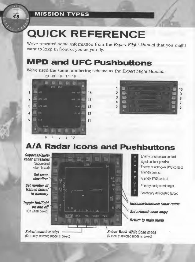
MISSION TYPES
QUICK REFERENCEWe’ve repeated some information from the Expert Flight Manual that you mightwant to keep in front of you as you fly.
We’ve used the same numbering scheme as the Expert Flight Manual20 19 18 17 16
' • T
- -- yxf. -fH- > il’ljtlM -B
; -a-
' ItHV -a
1
i
BIv]
< ,
1«—*
M
i :
*
JO ^1
'S'1^2^ c1 HI
rt 1 1 V 1 1 AN
BPL f.<H vs VCTK THS • 1
B1
—
*
5 B* T$0
1
X V, nt>^
’’
1
»' 1
6 ;

Ground Codes
position is from your aircraft)
Aircraft emitter
Missiie emitter
Icons with circles around
them indicate a threat
that has a lock on you.
Flashing icons indicate a
threat passing commands
to a missile.
Aircraft Codes|
14 F-14
15 F-15
16 F-16
18 F/A-18
21 MiG-21
22 Su-22
23 MiG-23
24 Su-24
25 MiG-25
27 Su-27
29 MiG-29
Aircraft Codes|
31
35 MIG-35/SU-35
40 F-111
41 Tornado
42 Tu-22
43 B-52
EW AWACSFI FI Mirage
F4 F-4E
F5 F-5E

COMBAT AIR PATROLPart of establishing superiority on the ground is making sure the skies belong toyou as well. Regardless of the lineup on the ground, whichever country maintainsair superiority over an area — meaning they are unopposed as they fly throughit — usually controls what happens below.
To maintain air superiority, most militaries opt to keep a nearly continuous fight-er presence in areas where trouble might occur. The ultimate purpose of a CombatAir Patrol (CAP) mission is to make a show of force to the enemy. The secondarypurpose, though just as important, is to detect trouble and immediately addressit if necessary . Pilots are sometimes restricted in the use of weapons and aren’tallowed to fire on enemy aircraft unless they’re fired upon first.
Most of the time, CAPs are flown near military boundaries or through no-flyzones. CAP flights usually involve two aircraft — one operating as the flightleader, and the other as his wingman. The wingman supports and protects theflight leader. The leader is the decision-maker and orders any offensive attack. If
anything goes wrong, responsibility falls upon the shoulders of the lead pilot.
The battle for air supremacy is on-going, and CAPs are sometimes flown in con-stant succession. During Desert Storm, for example, when one CAP fligh t
returned to A1 Khaij, another one departed. In this manner, American forces wereable to establish and maintain air superiority over the skies of Iraq.
CAP missions typically involve air-to-air engagements, and the fighters arearmed accordingly. Some pilots may say they prefer to cany along at least a cou-ple of air-to-ground mlssUes or bombs tn case important ground targets are dis-covered while they’re in the vicinity, but that is like bringing a knife to a gunfight.These weapons add weight, and you’ll be less maneuverable right when you needthe extra turning power.

COMBAT AIR PATROL
Combat air patrols generally fall into one of four categories:
• BARCAPs are barrier CAP patrols that take place along the edge of the battle
area and are defensive in nature. The idea is to make sure no unauthorized
aircraft cross over into friendly territory.
• On the more aggressive side, pilots in a MIGCAP mission spend their patrol
time hunting down enemy aircraft, attacking MiGs in particular.
• In a Target CAP (or TARCAP) , a flight flies over a specific target area to ensure
air superiority. These missions are designed to protect a target point — e.g.,
a bridge that friendly ground forces are about to take.
• Finally, in a Search-And-Rescue (or SARCAP) mission, fighters sweep the air-
space around a downed aircraft. Their job is to protect the crew until rescue
helicopters can arrive.
In F-J5, you’ll perform the CAP missions described above, plus a few variations
on the theme. For instance, in one of the campaign missions, you are tasked with
finding and protecting a search-and-rescue aircraft as it completes an extraction
mission. Some missions will give weapons-free status, meaning that you can
freely release weapons. Others will put you on weapons-hold status, meaning
you can’t fire first. Due to the fact that you’re often covering a lot of ground in a
CAP, these missions take longer than normed to complete. (You’ll probably find
the JUMP feature useful in these cases.) You may even occasionally have to refu-
el in mid-air.

Playtester Tipso If you aren’t looking for anything specific on the ground, fly with the A/A
master mode active on the way to the target. If any trouble arises, you’ll beready to pop off a few A/A missiles.
O Casual TEWS mode makes threat detection and identification a lot easier —enemies are red and friendlies are gray. You can switch modes in the Optionsscreen. (Go to the gameplay submenu, then select custom. Under tews, clickthe circle next to casual until a dot appears in it.)
O As an added bonus. Casual TEWS mode automatically gives you the directionand heading for any enemy plane within 40 kilometers.
O If you’re flying with realistic TEWS active, you’ll have to rely on the ID codesto determine whether a bogey is friendly or enemy. (All aircraft are repre-sented by an upside down V. Beneath the V is an alphanumeric code whichtells you what the aircraft is. A list of these codes appears on p. 49.)
O All aircraft show up as boxes on the A/A Radar MPD. As soon as you ndetect an aircraft, target it by left-clicking on it in the A/A Radar MPD. QThe blip on the radar will turn into an asterisk with a line. The lineextends out from the asterisk and indicates the target’s heading.
O Once you’ve targeted something, everything else disappears off of the A/ARadar MPD. Press [Bksp] to restore all icons onto the A/A Radar MPD. Or pressPB 10 on the A/A Radar page to select TWS mode — this keeps the targetdesignated, but puts nearby A/A contacts back on the screen.
O If you’re playing in Casual flight mode, you don’t have to send out an IFFquery to determine if the aircraft you’ve targeted is friendly. The targeted air-craft icon will automatically flash between an asterisk and a circle if it’s
friendly. If you’re playing in realistic mode, set IFF to auto (PB 3 of the UFCcycles through options) to have the computer send IFF queries automatical-ly; or set IFF to norm, and press (T) to send a squawk to your target.
O If you anticipate trouble, go ahead and press to get into MRM launchmode. This saves time later.

'V ACOMBAT AIR PATROL
hO Make sure your target is in range before you fire! Many missiles are
wasted by the simple fact that the pilot fired too early.
Watch the remge scale on the right side of the HUD. A missile’s max-
imum range will vary according to altitude, and this is factored in
when the targeting computer places range indicators on the scale.
Walt until the caret is Inside the brackets before firing. A shoot cue will
also appear under the target designator (TD) box when the target is with-
in weapon range.
O To make detecting your target easier, narrow the radar’s horizontal scan, but
increase it’s vertical scan. By flying in a circle, you can paint a larger picture of
the immediate area and catch things you might miss with a wider, shorter scan.
• Press PB 13 of the A/A Radar MPD to increase your radar range to 80km.
• Press PB 12 to set the azimuth scan angle to 15° (default is 30°).
• Press PB 2 to set scan elevation to 6 (the default is 2).
O Most CAP briefings recommend flying fast emd low. This helps you avoid
being detected by the enemy, since SAMs have a harder time seeing low tar-
gets. However, if you do fly low, remember to check above occasionally for
enemy aircraft.
O If you’re having trouble finding specific mission targets in a Single mission,
try opening the mission up in the Mission Builder. Look for objects with flags.
Green flags mark mission objectives — enemies that must be destroyed or
friendlies that must be protected in order for you to win the mission.
If the flag Is assigned to an airfield, specific target points are marked with red
triangles. For instance, an airfield attack scenario might have a runway,
hangar and control tower marked for destruction. You must hit (or protect)
some or all of the marked target points to win the mission.
O If you’re flying with limited fuel, take along four AIM- 120s, four AlM-9s, a
couple of air-to-ground weapons and one or two external fuel tanks. If your
fuel is unlimited, forget the tanks. Most missions will work with internal fuel
and one fuel tank if you don’t use afterburners very often.
O The CAS and Interdiction loadouts available in the Arming screen are good
for CAP missions. (For details on these loadouts. see pp. 216-221.)
2«
j»sl

Mission Parameters
Flight (Callsign) 2 X F-15E (Buick) Recommended Loadout CASMission CAP Environment/Time Clear/1800
Mission Intro
This mission represents a typical combat air patrol. You take off from Dubai International airbase, fly apatrol route around the Strait of Hormuz, then return to base. If you fly the mission as instructed, you won’t
run into trouble. Should you stray from the mission path, or take too long, the mission suddenly becomesmuch more Interesting.
Success
Moderate Complete patrol without firing on enemy aircraft or support FAC call; 65% friendly aircraft
survive; no friendly-fire losses _^
Perfect Complete patrol without firing on enemy aircraft; 50% special forces survive; no friendly air-
j
craft losses; no friendly-fire losses
Check your brief map.Before you even think about taking
off, take a look at your Briefing
map. The long, yellow line stretch-
ing across the width of the maprepresents the battle line. Abovethe line, Iranian aircraft are
patrolling the perimeter of theboundary. Below the line, you’re
flyring a CAP. Note that your flight
path never takes you into enemyterritory. If you follow the flight
path and don’t fire at anythingunless something fires at you first,
life will be uneventful. The missionlooks simple from this map, but if
you open this same mission in the
Mission Builder, you’ll notice that
it can quickly become complicated.

COMBAT AIR PATROL
Three things could happen:
1 . You follow your waypoints as planned. When you spot the Iranian F- 14 and/or
Su-25 along the way, ignore them. Complete your waypoints, then land.
2. You engage one of the “bait” aircraft (the F-14 or Su-25). This alerts several
flights of MiGs and F-4 Phantoms, which rush in to engage you. You have lit-
tle hope of surviving the attack.
3. You teike too long to complete your flight and receive an SOS from the FAC
(forward air controller) for intelligence-gathering forces on Qeshm Island. New
waypoints appear on your TSD, and your new mission objective is to support
friendly forces. You must destroy forces attacking them and return home
safely with all or most ofyour aircraft Intact. (You can simply go back to base,
but you won’t win the mission.)
Select A/A master mode.
O Your most time-consuming task during this mission is going to be scanning
the area with your A/A radar.
O You’re going to want to be in A/A master mode, which displays the A/A Radar
page (left MPD), A/A Arm page (center CMPD) and Tactical Electronic Warfare
System (right MPD). The majority of your attention should be focused on the
HUD in front of you, and on the A/A Radar MPD.
Select radar search mode.
O The A/A radar has several search modes, but you’ll really
only need to use RWSI (Range While Search Interleaved)
mode. To select this mode, press PB 6 in the A/A Radar
MPD until RWSI appears above the button in a box.
Three range-while search modes exist— RWSHforfinding
high-closure targets, RWSMforfinding low-closure targets
and RWSIfor detecting both high and low-closure targets.
(Closure indicates how fast the distance between you and another object is
decreasing or increasing. Positive closure means the object is moving toward
yow negative means it’s pulling away. High means the distance is charging
rapidly; low means that it’s changing slowly.)
O RWSI will be the search mode you use most of the time. For detailed expla-
nations of all A/A radar search modes, see the Expert Flight Manual p. 2.50.
1
•^1
1 H'
Al 1 \ 1 lA
•-
1
flSTn 11 VCU W 1

Adjust radar range.
O The range arrows on the right side of the A/A radar MPD let you adjust theradar’s range. The default range is 40nm, but it’s often helpful to zoom this
out to 80nm when you’re on a long stretch between waypoints. To increasethe radar range, press PB 14 (the up arrow).
Adjust radar scan.
O Next, you’ll want to adjust the portion of the sky that the radar scans.
By default, the A/A radar makes a two-bar sweep 30° to the right and left of
your aircraft’s nose. This is fine if a bogey is flying at approximately the samealtitude as you are, but it’s not good at detecting targets above or below you.
O For this mission, you’ll probably want to make the scan azimuth (horizontal
scan) narrower and the scan elevation (vertical scan) taller. The advantage to
doing is that you will have a better chance of spotting bogeys at different alti-
tudes.
• To increase the scan elevation, press PB 2 (el) on the A/A radar page. Scanelevation can range from 1 to 8 bars — set it to 8. A “bar” is basically a sin-
gle radar sweep. When the radar is set to scan multiple bars, the antennawill make a sweep, then move up and make another sweep in the oppositedirection. The more bars it sweeps, the greater the vertical area scanned byradar.
• To decrease the scan azimuth, press PB 12 (az) on the A/A Radar page.Scanning the default azimuth, with an 8-bar scan elevation, causes theradar to update quite slowly.
O You can compensate for this narrower scan by fl)dng a “weave” pattern, point-ing your aircraft’s nose left for several moments, then pointing it back right.
Or, you can occasionally fly in a circle to pick up a 360° view of what’s aroundyou.
1
:
U J ( 3•C
iWO^Dar sC3fl1 d
Increasing the number of
bars the radar scans - Dincreases the height of
the scan area. Six-bar scan
A tall, narrow scan
area will help you
find aircraft at
different altitudes.
You can then weave
or circle to cover
more horizontal area.

COMBAT AIR PATROL
Identify bogeys.
O One you pick up radar contacts (there are two in this mission), your next step
is to determine whether they are friendly or enemy.
When the radar first paints an unidentified aircraft (called a bogey), a small
rectangle appears in the A/A Radar MPD. By this icon alone, you won’t be able
to disUngulsh what type of aircraft it is. However, you can target it and then
send out an IFF (interrogation friend-or-foe) query to determine its status.
(Also, if the aircraft is transmitting radar, it will show up as a threat icon with
an identifying number on the TEWS MPD. See list on p. 49.)
O To target an aircraft, use your mouse to left-click on one
of the small rectangles in the A/A Radcir MPD. This sym-
bol will change to an asterisk with a line attached to it.
This line is called a heading vector and indicates the
direction in which the aircraft is moving. The A/A radar
displays a top-down view of the air in front of your air-
craft — if a contact’s heading vector points downward,
the aircraft is pointed toward you. In the picture to the right, the contact is
moving away from you.
O Note that the second aircraft disappears from the radar. This is one drawback
to the RWSl search mode. If you’ve detected several aircraft, targeted one,
and want to re-display all aircraft, press |Bksp| .
Note: A second radar search mode, TWS (track-while-scan) can display the
targeted aircraft, as well as other aircraft in the area. However, it has an
extremely small scan size. TWS is most useful after you’ve designated a target
in RWSI mode and want to keep an eye on your current target, while display-
ing the other aircraft near it on the display.
O Finally, query the aircraft by pressing Q. If the asterisk flashes and turns into
a circle, the target is friendly. If not, it’s enemy. In actual combat missions,
you’ll probably want to arm your medium-remge air-to-air missiles. For now.
however. Just practice targeting any aircraft you see, then sending an IFF
query. Remember that in this mission, you’ve been instructed to hold your fire.
O The AN/AAQ-14 target IR pod can track airborne targets that fall within the
field of view of the seek hear. If you have a target designated in the radar and
have the Target IR MPD displayed, the pod will attempt to follow the target.

AIR INTERCEPTThe F-15E may be a ground-pounder at heart, but even today it preserves theheritage of its air-to-air predecessors. Historically, the F- 15 series of fighters hasfulfilled the air superiority needs of the USAF. The Strike Eagle version still doesthis, but it is just as adept at taking out ground targets as intercepting air adver-saries.
An air intercept mission is normally an immediate response to Incoming enemyaircraft, and often occurs in friendly territory close to base. Intercept flights aresent out to meet enemy strike fighters or bombers with fighter escorts. The offen-
sive flight’s intent is to attack strategic, friendly ground targets. In an edr inter-
cept mission, it is the defensive flight’s job to prevent this from happening.
Because bombers and escort fighters maintain formation until they reach thetarget area, most air intercept missions take place at high altitudes. The heightadvantage comes into play in these battles — whoever has the most altitude pos-sesses the immediate advantage. (Height translates into airspeed during a dive,
while climbing to meet a higher foe consumes airspeed.) Height also gives yourair-to-air missiles better range, since they also trade altitude for speed.
Since bombers are heavily weighted with ordnance and not very maneuverable,height isn’t much of a factor when attacking them. However, altitude becomesmore important against their maneuverable fighter escorts, which will break for-
mation in order to meet an attacking flight.
An air intercept mission against a lone pair of enemy aircraft may only scramblea single flight, although two flights are the norm. If the mission is a bomber inter-
cept, more flights may participate. In the case of bombers, each flight is taskedwith a particular target— one might attack the escort fighters, for instance, whileanother goes after the bombers. A third or fourth flight can serve as backup andassist either group as necessary.
In the game, you usually draw the duty of destroying incoming bombers, whileother flights dispense with the escort fighters. If no bombers are present, you’ll
take on strike fighters. Since this mission type is defensive and requires imme-diate response, your briefings will usually be short and to the point. Most air
intercept missions have some sort of built-in Uming mechanism. If you don’tdestroy the strike fighters or bombers in the time allotted, the mission will fail.

Playtester TipsO In most cases, incoming and intercepting aircraft number quite a few, and
the skies will be filled with both friendly and enemy aircraft.
O In bomber-intercept missions, computer-controlled flights don't always
destroy escort fighters as quickly as you need them to. If this happens, you
might have to knock out a fighter or two yourself.
O Don’t expect non-player flights to help you with bombers after they’ve killed
off the fighters. They rarely do.
O The biggest problem during an air intercept is distinguishing between friend-
ly and enemy aircraft. The next biggest difficulty is telling enemy bombers
and fighters apart. (Using the Casual TEWS can help here — it displays
labeled, color-coded icons to ID aircraft for you.)
O Make sure you know what you’re firing at before you launch! You don’t want
to waste precious air-to-air ordnance on a MiG if you’ve been tasked with the
bombers.
O The IFF query function comes in handy when you’re trying to ID aircraft. If
you’ve got Expert TEWS active in the Options menu, all friendly aircraft will
emit an Interrogation Friend or Foe (IFF) signal. Initially, all aircraft show up
as rectangles on the A/A radar. If you left-click on one of these contacts, it
switches to an asterisk, and everything else disappears off of the radar. To
query the aircraft, press |T). If the star turns to a circle, then the aircraft is
friendly.
O If you press PB 3 on the UFC until the text beside it reads iff auto, a contact
will automatically be sent an IFF query when you choose it as a target.
O If you need to query other contacts, press |Bksp| to undesignate your current
target and restore all of the blips on the A/A Radar MPD.
O Go in high whenever you’re attacking enemy aircraft. The more altitude you
have, the better.
O Ideally, you want to take missiles that will let you hit a bomber head on.
AMRAAMs can attack a target from almost any aspect angle. This means that
you don’t have to fire them at the target’s tall. AIM-9Ms are all-aspect as well,
although the older AlM-9Ps require you to aim from the rear.

O Bombers are, for the most part, cargo planes canylng lots of weapons. It
doesn’t take much to destroy them, so you can hit them with whatever youwant, including your cannon.
O Tu-22s have a rear tailgun — watch out for them.
O You can detect a target long before you can successively launch a missile
attack. It’s tempting to fire away as soon as you spot one — don’t give in to
temptation.
O If a bomber or escort fighter is closing fast on your nose, you can actually fire
Just outside the missile’s maximum effective range. Since you’re fl3dng towardeach other, the target will be in range by the time the missile activates.
Conversely, you can’t do this if you’re chasing from the rear and the target is
pulling away from you — don’t fire unless it is well within the missile’s effec-
tive range. If the target has a high, negative closure rate, the missile mightexpend its fuel before it could catch up.
O Try 6 AIM- 120s and 2 AIM-9Ms for a bomber intercept loadout. (These aren’t
always plentiful in a campaign, however:)
O You can make a vertical dive down onto a bomber, especially if you’re usingshort-range weapons.
O When you target an aircraft while your IFF is set to auto, a target designator
(TD) box will appear around it on the HUD. If you’ve accidentally targeted afriendly aircraft, an “X” appccirs through this TD box.
O Single Target Track (STT) mode is the default tracking mode for the A/Aradar. However, in this mode, cill other targets disappear except for the oneyou’ve designated.
O If the air is thick with aircraft, you probably want to switch to TWS (track
while scan) mode for your A/A radar. This mode lets you designate a single
target but still see everything else around within your radar’s field of view.
This is especially useful when you’re using AIM- 120 AMRAAMs, each of
which can be fired at a different target.

O With AMRAAMs, you can select up to eight targets before firing a single mis-
sile. When you left-click on a contact in the A/A Radar MPD, that contact
becomes your prlmaiy designated target (PDT). Ifyou select a second contact,
the most recent one becomes the primary target, and the original target
becomes a secondary designated target (SDT). The last contact you select is
the primary target, so be aware of the order in which you select targets.
Secondary designated targets appear as a hollow box with a heading vector,
while the primary designated target has the usual asterisk or circle “head”
with a heading vector.When you launch the first AMPiAAM, it will aim for the
PDT target. Subsequent missiles will take on each SDT, starting with the
closest.
O AlM-7 Sparrows require that you keep the target within your radar’s cone of
view for the duration of the flight. Don’t turn or pull up, or you’ll lose the lock.
O AlM-9 Sidewinders (all models) hold their target after launch and follow
through on the attack without the help of your radar.
O A1M-9PS can only be fired at a target’s rear, since they lock onto hot tailpipes.
Carrying the A1M-9M or A1M-9L is preferable, since they’re all-aspect missiles
and it doesn’t matter what part of the target you’re facing when you fire.
O Use your Sparrows against the bombers (which don’t move as fast as fighters
do). Save your AMRAAMs for the fighter escorts.
O Tiy to get really close to your acquired target before firing Sidewinders. They
operate best at close range.
O The AAQ-13 LANTIRN navigation pod is useful in any mission, but especial-
ly in missions in which you are flying low or over mountainous terrain. The
navigation pod houses a terrain-following radar that conUnuously calculates
the height of the terrain beneath you.
It is also especially useful when flying at night — the NAVFLIR camera which
it houses projects a FUR image of the air and terrain in front of you onto the
HUD. At night, this infrared image makes it easier to distinguish between the
ground and the sky.
O You’ll find RWSI mode best for detecting helicopters. Not in this mission, of
course, but it can be useful.

MISSION TYPES
Example: Rghtei^Bomber Intercept
4 X F-15E (Outlaw); 4 x F-16 (Medusa)
Bomber Intercept
MigCAP
Clear/1400
Mission Parameters
Flights (Callsign)
Mission
Recommended Loadout
Environment/Time
Mission Intro
Enemy bombers and their fighter escorts have
been spotted and are headed to raid a friendly
airbase on Khark Island. Your task is to inter-
cept the bombers and eliminate them before
they break through friendly fighter defenses.
Secondary to this, you’re to take out the fighter
escorts.
Success
Moderate
Perfect
Destroy ail four Tu-22 bombers;
_5-+ friendly aircraft survive
Destroy all four Tu-22 bombers;
no friendly aircraft lost
y Your
/ approach
(4) Tu-22
(2) Su-35X
(3) MiG-21.^ 10> (3) F-4
Set up for air combat.
O This mission begins in the air. The first thing you want to do is switch to A/Amaster mode.
O Next, select the A/A Arm MPD in the right MPD (or press |F 2|to view it on
your lower MPD). This shows your air-to-air ordnance stations. Short-range
missile stations are labeled srm, while medium-remge stations are labeled
MRM.
O Press to switch to medium-range missile (MRM)launch mode. This readies you to fire your AIM- 120 andAIM-7 missiles (in this case, AIM-120s). Note that rdy
appears above 120a and is boxed — this indicates that
the AMRAAM is the active missile, or the missile “in pri-
ority.”

O In the future, press(2] to switch to short-range missile (SRM) launch mode in
order to fire AIM-9s (if you have them loaded).
O Notice that there is no key for selecting individual missiles — you simply
select short-range or medium-range, and you fire off missiles within that
group in a certain preset launch sequence. But what if you had, say, a mixed
MRM loadout of AIM-7s and AIM- 120s, and you wanted to use the AIM-7s
first and save the AIM- 120s for later? You can press (7) to “reject” a missile
8md skip to the next missile in sequence. You would keep pressing @ until
RDY appeared above a 7f or 7m station on the A/A Arm MPD.
See Elxpert Flight Manual p. 2.26, for more information about the A/A Arm MPD.
O Now, re-display the TEWS emd look for air threats and ground threats. Note
that in Expert mode it will only display these threats as long as the threat’s
radar is active. (Casual mode displays everything that’s out there — within a
range you set — regardless of sensor status.)
O The above information generally means:
• Fighters will only show up while conducting a radar scan, locking onto a
target or feeding guided information to a radar-guided missile. If they know
where you are, or if they are using IR missiles, they might srvitch off their
radar and disappear from the TEWS.
• Bombers, however, won’t show up on the radtir unless they’re locking you
up with their gun.
• Only an active radar-guided missile will show up, and then only after the
radar system in its nose has activated. If you were fighting Americans, this
would mean the AIM- 120 would show up, but the AIM-7 wouldn’t.
O The TEWS Eilso displays information about chaff, flares and Jammers. By
default, the TEWS automatically controls chaff and jamming. You can take
care of these yourself by selecting PB 20 (man/semi /auto), which changes the
level of countermeasure control. AUTO mode lets the TEWS drop chaff and
activate jammers. SEMI lets the TEWS control the number of chaff pods
dropped per release, but you release them manually. You have control of the
jammer. MAN gives manual control of everything.
O You have to dropJlares manually no matter which TEWS setting is active.
O Note that your WSO calls out threats and incoming IR and radar-guided mis-
siles. Leeirn to release countermeasures on his cue.

\si j /Find bogeys.
O The bombers and escorts are directly in front of you at a slightly higher alti-
tude. Climb up, and then get ready to search for targets.
O A quick way to identily the general direction is to request AWACS information
(IShift I Tab I
menu), if an AWACS flight is nearby. Otherwise, you’ll need to searchmanually on your radar or by using one of the F-15E’s search modes.
Select a target acquisition mode.O You can left-click on radar blips in the A/A Radar MPD, or target them auto-
matically. The F-15E has four missile acquisition modes, plus one gun acqui-
sition mode. AU are used to acquire targets. (These modes should not be con-fused with radar search or tracking modes. Search, acquisition and tracking
modes are discussed in the Expert Flight Manual on pp. 4.29-4.30.)
• Supersearch acquisition mode ((TD will pick up bogeys that pass through a20° cone in front of your aircraft. Although this mode looks for targets in alarge area, range is limited to lOnm. This is good if you’re tiying to pick upthe closest target in a missile fight or flying CAP and covering a wide areawith your radar, but not if you’re tiying to pinpoint a pair of inbound fight-
ers and know their exact direction of approach.
O For this mission, use the super search mode. The bombers and their escorts
are a mere 17nm ahead of you, and closing fast.
'K
• Long-range boresight(( 7]) looks for targets in a very small area just
around the waterline (^). In this mission, you won’t need to use this
mode. However, if you ever request a bogey picture from an AWACS aircraft
Q Shift ff) , then [j]), you can change course to match that bearing and use this
mode to detect fighters up to 40nm away. You can do the same if you knowthe bearing of am attack on a friendly facility that you’ve been sent to pro-
tect.
• Boresight ((6]) also looks for targets in a small circle around the waterline.
This mode is best applied when you know the bearing of an approachingfighter or group of bombers, amd they’re already within close ramge (lOnmor less). Or, if you’re on someone’s tail and want to maintain a lock on that
specific target, use this mode.
I'.:
15

n-
• Vertical scan mode ([U probably won't be too useful in a missile fight. This
essentially turns the radar seem vertical instead of horizontal, meaning you
can then find targets in a tall, but very narrow, band of detection in front
of your aircraft. It is generally reserved for close-range fights in which
you’re trying to acquire em enemy in front of you as he makes a break turn
to evade you. The taller, vertical scan will let you track him further into the
turn than you can with other modes.
• Guns acquisition mode activates automatically when you select your gun
while in ATA master mode. Its range is barely 5nm, but it has a large acqui-
sition area. The different gunsight modes are discussed later, on p. 67.
Find and track a Tu-22 bomber.
The hardest part of this mission is sorting out the bombers and fighters in
front of you. There’s no easy way to tell them apart. With ground targets, you
can at least use the Target IR MPD to see a FUR image of the target. Air tar-
gets won’t sit still long enough, so you can’t rely on imaging to distinguish
one plcme type from another. You can send em IFF query {[T]) to discern
between friendly and enemy planes, however.
O You can play with the casual tews option active — the TEWS then shows
bombers even when they aren’t using radar, and identifies threats for you.
If you don’t want to do this, one trick that can help you ID your target is to
pause the game and enter the Reverse Tactical view (IShiftlF?|in the default key
map). This gives a view of your target, and of your aircraft from your target’s
perspective — which tells you a bit about how to turn to find that target.
k
There’s no easy way to identify a bomber legitimately. You can make an edu-
cated guess by checking a target’s closure rate — if it is fairly low even when
he’s approaching you head-on, he could either be a bomber or a slow-moving
fighter. If the closure rate is really high, it’s most likely a fighter. (Subtract
your speed from the closure rate to estimate your target’s speed.)
Once you’re fairly certain that you have a bomber designated, you may want
to switch to track-while-scan (TWS) mode. This allows you to track the target
you’ve designated, but it also keeps other air threats displayed on the radar.
Note: You can't activate TWS tf you have an AIM-7 ready. It allows you to track
only a single target, and requires that you keep that target within your radars
cone of sight until it hits.

O Tws mode is especially useful when you’re using AMRAAMs because you’reable to designate primaiy and secondary targets. Once you have several con-tacts in the A/A radar MPD, you can pause the game and left-click on all ofthem. (If you haven’t designated a certain target before you activate TWSmode, the closest contact will be automatically targeted.) The last one youselect is your primary designated target (PDT), while the first ones you select
are secondary designated targets (SDTs). The first missile fired will go for thePDT, while others go after the SDTs.
Fire an A/A missile.
O Once you’ve got a bomber designated, the rest is easy. Maneuver so that thetarget you see in your A/A Radar MPD is in front of you. It will appear as aspeck in the sky with a target designator (TD) box around it. (If you’ve sent anIFF query and the TD box has an “X” through it, then the target is friendly.)
O When the target is within range of the weapon that is in priority a shoot cuewill flash beneath the TD box. (See the pictures below.) When you see theshoot cue, fire using joystick button 2.
•
AIM-1 20 shoot cueI ^ I
AIM-7 shoot cue AIM-9 shoot cue
O You won’t see the cue until (a) the target is within missile range, and (b) themissile has a lock. If the cue is flashing, you’re in optimum firing range. If it
doesn t flash, you can still fire, but the missile may mn out of energy beforeit catches the target. Or, the target might evade it. (Several subtle firing con-siderations can improve your missile’s chance of hitting. See the Expert FlightManual, pp. 4.34-40, for complete instructions.)
Note: If a large X fills the HUD when the target is in your radar's cone of view,your target has moved inside the selected missile's minimum range. You will needto adjust your position, or select a shorter-range missile.
O A1M-9PS must be fired toward a target’s rear, but the other air-to-air missilesyou can load are all-aspect. This means you can be facing the target at anyangle when firing.

Ifyou need to, use your guns.
O Normally, you won’t rely on guns. Use them only when you’re short on mis-
siles or happen to be too close to an enemy aircraft to fire a missile.
O Press (T) to select your gun. This places a funnel-shaped curve onscreen,
which twists and changes shape as you maneuver. You stand a better chance
of hitting targets near the open mouth of the funnel (targets that are within
1000ft) than targets at the smallest end of the funnel (targets within 3000-
4000ft). Maneuver so that your target is “inside” the funnel, then press the
joystick trigger to fire.
O The funnel is useful ifyou understand its purpose. Ifyou
have a long, skinny funnel, it means you’re currently
pulling hard-G maneuvers to bring the target into your
bullets’ rcinge. A wide, short funnel means you’re not
maneuvering very sharply. Either way, you want to
maneuver so that your target’s wings touch both edges of
the funnel (see the picture below). In other words, the
target’s wingspan should “fill” the width of the funnel. If
the wings don’t touch both edges, then you want to
maneuver so that he’s further down inside the funnel.
Target property
aligned in gun
funnel
O If you have a target designated with your radar, you have
a second gunsight option. Pressing [T] again places a
round GDS reticle onscreen Instead of a funnel. This is
slightly easier than using the funnel— here, steer so that
you place the reticle up on top of the target, then fire. The
reticle indicates the point through which bullets will pass
at you’re target’s range.
O Pressing (T) a third time displays both the funnel and
GDS reticle. If you normally use the reticle, you maywant to use this mode to get a feel for how the funnel
works. Just line up the reticle and the target, then pause
to see where the target falls inside the funnel.
Here, you would want to
maneuver until the target
in the TO box was nearer
the neck of the funnel
where the reticle is.

MISSION TYPES
STANDARDBOMBING RUNThe F- 1 5E is a strike fighter, and bombing fits well within its repertoire of attack
capabilities. Just about every strike task that isn’t specifically geared toward
ground threats, airfields and ships fits into this category. For instance, teirgets
may include factories, bridges, roads, hardened command bunkers and strategic
buildings. If the target is well defended, a Suppression of Enemy Air Defense
(SEAD) flight may be sent in ahead of a bombing flight in order to clear out dan-
gerous SAMs and AAA sites.
Although sheer explosive power is the hallmark of a bombing attack, guided
munitions have their place in ensuring mission success. Sometimes, the target
of a bombing attack will be adjacent to civiliEm facilities. Or, only the destruction
of part of a target is necessary to deny the enemy immediate, military use of its
resources — i.e., taking out fuel tanks or pipelines in lieu of taking out a refin-
ery. In these cases, using precision-guided munitions ensures that a) weaponexpenditure is kept to a minimum and b) only the intended target is damaged.
To ensure that no unintended targets are hit, the attacking flight must first des-
ignate the correct target. A good visual ID or infrared image of the target is nec-
essary for weapons launch, and the launching party must be sure that the tar-
get is indeed a strategic objective. As witnessed during Desert Storm, misguided
precision weapons can have disastrous results. Two cases in point are the
destruction of a civilian shelter using an laser guided bombs, and a Hellfire
attack on friendly tanks by an Allied helicopter.
Playtester TipsO Once you’ve successfully fulfilled your mission objective, you can press |Esc|
to end the mission. This is especially useful if you’re running low on fuel.
O If you’re still learning, use the easy landings and crashes off options. That
way, you won’t get through a mission only to crash during your landing.
O If you have a hat on your joystick, press the hat down to see a head-downview of the cockpit. flF2 |
will accomplish the same thing, and |F1| or pushing
the hat up will restore the normal cockpit view.)

o Here’s a general tip — if you make a custom ke)miap, you can open it as a
text file and print out a list of your new keys and their functions. The file is
in the Jane's/FI 5 folder on your hard drive (or in whatever folder you chose
during installation) and has the name you specified, followed by ini (for exam-
ple, mykeys.ini). Don’t modify this file outside of the game, however!
O After you take off, tell your wlngman to engage targets of opportunity. To send
this message, press (^, then press @ to select wingman from the message
menu. Select ground targets (press [e]), then targets of opportunity (press [3]).
O The above command can be assigned to a custom keymap by adding the
ATK_ANY_GRND function to an unmapped key.
O If you don’t have specific targets to hit, circle the target area and scan with
your A/G radar until you detect targets. Keep your altitude under 1000ft.
O Make sure you keep A/G master mode active. If you accidentally switch to
A/A master mode, you won’t be able to see any ground targets.
O You have to load countermeasures onto your aircraft for each mission. If you
think you’ll be facing a lot of SA-13s, take along the package with the most
flares. If you’re facing predominantly radar-guided SAMs, take more chaff.
The following packages eire aveillable: AN/ALE-40(1) — 120 chaff/60 flares;
AN/ALE-40(2) — 180 chaff/30 flares; or AN/ALE-40(3) — 60 chaff/90 flares.
O YourTEWS won’t control flare release. Even in AUTO countermeasures mode,
you have to manually drop flares (finsD .
O SA-13s fire heat-seeking infrared missiles. If your WSO calls for flares, dis-
pense flares, then turn your afterburners off (press Q-
O Sometimes in a mission, you’ll be ordered to not hit a certain target — for
instance, you might hit fuel tanks, but not refineries. Precision weapons (i.e..
Mavericks and the GBU bombs) are best for these occasions. Chances are
that if you hit something you’re not supposed to, you’ll fail the mission.
O The standard loadout in the Arming screen is good for bombing runs against
medium-sized targets— command bunkers, fuel tanks, etc. Most of these are
dumb bombs. For your guided weapon needs, try the Smart Bomb loadout.
O Low and fast Is the best approach for a mission against tanks — you’re usu-
ally traveling 600 knots or faster, and it’s hard for tanks to fire at you.
O If you’re attacking a large target or using self-guiding weapons, you can
afford to go in high. It keeps you out of AAA remge and some SAM ranges.
/-I
MV

K *'r **•
*< .
// .
''
Example: Chemical Attack — IraqMission Parameters
|
Flights (Callsign) 8 X F-15E (Outlaw); 6 x F-15C (Medusa); AWACS (Bandsaw)
Mission Strike
Recommended Loadout Standard
Environment/Time Partly Cloudy/1955
Mission Intro
This mission represents a standard bombing run— your flight’s objective is to attack a chemical weapon
production facility in the Mid-East. The attack must be swift and accurate to avoid fighters that will most
likely scramble when you arrive. For political reasons, you've been instructed not to engage any other tar-
gets of opportunity, including enemy aircraft.
Success
If you use this mission for countermeasures practice, the objective is simply to stay alive.
To win this Single mission, however, you must meet the success parameters listed below:
Moderate Destroy four northernmost buildings, damage SE building; 65% friendly aircraft survive
Perfect Destroy all buildings (or at least destroy the four northernmost buildings and damage the SE
building); no friendly aircraft losses
Find the complex.
This is another nighttime bombing mission, but
you shouldn’t have a hard time finding the tar-
gets. You’ve been tasked to hit five different build-
ings in the complex, and they’re all clustered
together. As soon as you approach steer point 5a,
start looking for green specks in your A/G RadarMPD. If you follow your steer points, you’ll fly
toward the target area.
AAA Site(s) I
SAM Site I
SAM Radar f
Note: Since this mission has so many SAMs and AAA, we are going to concentrate
here on teaching you how to avoid them. Ifyou want to also make a bombing run,
the methods forfinding targets and engaging them are discussed under CombatAir Patrol, p. 50, and SEIAD, p. 80, respectively.
. 9 -

STANDARD BOMBING RUNW-
Avoid ground threats.
O If you’re flying this mission strictly to learn how to avoid ground threats, make
a low-altitude run. SAMs will have a harder time tracking you.
O Not getting shot down is going to be your biggest problem in this mission.
Anti-air defense is heavy — strikes on most strategic targets will require you
fly within range of the SAMs that are protecting them, and this one’s no
exception.
O SAMS send out radar spikes when they’re trying to acquire you. Your WSOwill identify these radar searches as “mud spikes.”
O A SAM’s TEWS icon will flash when it is launching a mis-
sile at you. Arrows on each side of the TEWS flash to let
you know from what direction the missile is approaching.
If it’s on your left or right, you stand the best chance of
evading it. If you’re being tracked by a missile, turn
toward the flashing arrow (if it’s on the left, for instzmce,
steer left). Missiles expend most of their fuel and energy
by tracking you into the turn. You want to keep your
speed as high as possible to make them maneuver more.
Note: Some missions (but not this one) have SA-13 SAMs, which fire IR-guided
missiles. This turning technique won’t work in theses cases. Instead, dropfiares,
shut your afterburners ojf and get outfrom between theflare and the missile.
’.J«,
J*
Use countermeasures.
O At first, you’ll probably want the TEWS to take care of chaff and jamming.
You must always drop flares manually, however (press [InsD .
O When the TEWS countermeasures setting is AUTO, you’ll get an audio cue
each time the TEWS drops chaff or activates jamming. (The TEWS dumps
chaff rather quickly. When you’re a little better at evading missiles, switch to
MAN mode and drop these yourself.)
O If you’re in SEMI or MAN mode, you’ll have to manually turn on your jam-
mers on ((3) and manually drop chaff ([Del p .

CLOSE AIR SUPPORTClose Air Support (CAS) missions involve attacking ground targets, not air tar-
gets. They are offensive in nature instead of defensive. A Strike Eagle flight on aCAS mission has predetermined targets gathered by intelligence forces, and the
sole purpose of the mission is to take them out. The idea behind a CAS effort is
to soften up enemy ground targets prior to the arrival of friendly ground forces.
Or, friendly ground forces may be under attack and need help defeating enemyground forces from above. Therefore, most Close Air Support missions take place
either behind enemy lines or on an advEmcing battle front.
/
The targets assigned to CAS flights are limited to vehicles or emplacements that
could potentially harm friendly ground forces or arriving attack aircraft. Thesehigh-threat targets include tanks, mobile and stationary SAM sites, and long-
range artillery. Larger targets like airfields and stationary radar sites are left for
the arriving strike or SEAD aircraft.
In a CAS mission, you typically make a high cruise approach. Once you’re with-
in detection range, you drop to a lower altitude to avoid being detected by enemyradars and SAMs. (Think of their detection area as a large cone standing on its
tip — near the ground, the detection range is small. As the cone travels upward,it moves outward, and the detection range increases.) On your exit, you’ll fly outlow, then gradually climb to a safe cruise altitude.
In the game. Close Air Support missions are among the most difficult tasks you’ll
be handed. Small targets on the ground are hard to find and even harder to hit.
CAS flights are a bit easier in Single missions them in Campaign missions, at
least as far as ordnance is concerned. In the Campaign, you’re trying to manage, finite supplies of aircraft, dumb bombs, guided bombs and missiles. In Singles,
you don’t have to worry about conserving certain weapons for later missions.
If Playtester TipsI
.i O CAS missions usually send you to a specific target area (check your briefing).
If it’s a CAS mission, it will usually mention a friendly advance.
O You can play with the invulnerable and/or unlimited ammo options active in
'
fSingle missions. However, they automatically deactivate in Campaign missions.

a You will need to make HRMs to pick out your target (see p. 23 in this book,
or p. 4.53 in the Expert Flight Manual). If you can’t find a target in your map,
change altitudes or adjust the radar scan. At higher altitudes, you get more
range but less detail. Lower altitudes give better detail, but less range.
a If you get an error message when you click on the radar screen to command a
map, your radar can’t “see” well enough to create a map. You either need to
turn slightly to avoid the “blind” radar spot that occurs at 8° to the left and right
of your edrcraft’s nose, increase the radar’s range, or decrease the HRM size.
a Since you’ll often be flying low, near SA-13s with IR missiles, you may want
to take along a flare-heavy countermeasures package. Do this in the Arming
screen before you take off. First make a pass to find those SAMs (dropping
flares all the way) and take them out before you start hitUng other targets.
a Press (£13 to pop down and look at the TSD every so often, or pull up the TSD
in the right MPD in place of the A/G Arm page. (If you have a joystick with a
hat, push the hat down to switch to the |F2|view.)
0 If you know you’ll be facing tanks, carry Mk 20s (unguided bombs) or AGM-
65s (guided air-to-ground missiles). Mk 84s are great if you’re into large
explosions, but it’s a shame to waste them on smaller targets.
0 The Jump function can be really useful for long-range CAS missions. It lets
you skip all the way into enemy airspace and places you at the waypoint
nearest to the target area.
0 If you’re having trouble with attacking or navigating at the correct altitudes,
try switching to Casual flight mode for a mission or two. By using the
Autopilot function in Casual mode, you can watch to see what altitudes work
best for each waypoint. Be careful about autopiloting in Expert flight mode,
however— by default. Expert autopilot maintains your current direction and
angle-of-attack. Even if there is a mountain in the way, it won’t readjust your
altitude or direction.
O Flying high on the way to the target area is the most fuel-efficient way to fly.
Usually, 25,000ft of altitude and 350 knots of indicated airspeed works well.
If you’re not concerned with fuel, you can fly low to avoid radar detection, but
you can’t see as well.

wmMISSION TYPES
Example: TACAIR (Detection Phase)IMPORTANT! To avoid information overload, this single mission has been dividedinto two phases — detection (finding and acquiring targets) and attack (using air-
to-ground weapons against targets). Thefirst phase is discussed here, under CloseAir Support. The second phase is discussed under Suppression of Enemy AirDefenses, p. 80. The mission itself is a CAS and SEIAD combination mission.
Mission Parameters
Flights (Callsign) 4 X F-1 5E (Charger); 2 x F-4G (Raven); 6 x Jaguar (Cortland)
Numerous other AWACs and supporting aircraft.
Mission CAS/SEAD
Recommended Loadout LONGCAS, but replace one rack of Mk 20s with four GBU-1 2s and add the
AN/AAQ-14 pod.
Environmentdlme Clear/1430
Mission Intro
In this mission, coalition forces are about to move in on dug-in Iraqi positions on the coastline of Saudi
Arabia. Your flights' job is to help the Jaguars soften up the Iraqi air defenses prior to a massive airstrike.
Destroy as many AAA and SAM sites as your weapon load allows.
^Slight Destroy 16% to 40% enemy ground targets; 70% friendly aircraft survive
Moderate Destroy 41 % to 70% enemy ground targets; 70% friendly aircraft survivg
^High Destroy 71 % of enemy ground targets; 70%^friendly aircraft survive
Perfect Destroy 71 % of enemy ground targets; no friendly aircraft losses
Before You Take Off ...
You’re going to need air-to-ground
weapons for this mission (Mk 20s andGBU-12s), a few air-to-air missiles for
enemy aircraft on CAP, a FLIR pod,
and some extra fuel for the nearly
300nm trip north to the target area.
The recommended LXDNGCAS loadout
includes most of these, but you’ll haveto add the pod and GBU-12s using the
CUSTOM loadout button.

After takeoff, head for your next steer point
O It’s a long way to the next steer point, so unless you’d like to spend some time
cruising, you might want to use the Jump flShiftfjD function.
O If you’re having trouble distinguishing your HUD readout from your forward
cockpit view, you can change the color of the HUD display by pressing [Help]
until you cycle through to a color you like.
O Jumping drops you Just outside the target area at Nav 3A and at nearly
20,000 feet of altitude. At this point, the Jaguar flight splits off to the north
to take on a group of SAMs and AAA.
O While you’re still in Nav master mode, note the triangle on your A/A radar
page. This is your target sequence point, or in simpler terms, the last way-
point before you hit the target area.
O As you approach the target area and prepare for your attack, go ahead and
issue your wingman the command to attack the primary target ffab], then (T|,
d], and Q]). That way, he’ll get into action as soon as you arrive.
Activate A/G master mode. .
O Now, you’re going to want to switch to your A/G radar in order to scan the
area for targets. Cycle through to A/G master mode (press until a/g lights
up on the bottom of your screen). This displays your A/G radar in the left
MPD, the TEWS MPD in the right MPD and the TSD MPD in the lower, center
CMPD. See Quick Reference, p. 49, for A/G radar pushbuttons and symbols.
Select the radar mode.
O The A/G radar has four modes. Only one mode is mentioned in detail here —RBM (real-beam map) mode. This mode is what you’ll need to detect station-
ary targets on the ground, rbm is selected by default on PB 6, and you’ll want
to use this mode most of the time.
O For moving teirgets in other missions, you can use GMT, or ground-moving
target mode, which is discussed in the Expert Manual p. 2.46.

MISSION TYPES
Find the target area.
O Fly through the next steer point, bank right, and proceed forward towardyour target sequence point, making sure you keep your altitude constant.
(Steer points appear on your A/G radar screen as circles.)
O As soon as you spot light-green clutter near the center of your radar, zoomthe radar in from 40nm to 20nm (left-click PB 13, the down arrow). This will
provide a close-in view of the area.
o
o
Fly forward and veer slightly left to move the clutter off
center. When it’s approximately in the right, middle sec-
tion of the MPD, pause the game flAlt fFD and study yourradar.
By default, you are using the radar cursor’s MAP function
(versus the Target (tgt) function). The current map size is
4.7nm square. (As a side note, each time you zoom in the
radar, the map size gets smaller as well.) Since you wantto see a smaller area than 4.7nm, reduce the map size bypressing PB 8 once. The screen doesn’t change any, butthe map size you are about to create will be 3.3nm square
Make a High Resoiution Map (HRM).O Now, move your mouse cursor around in the MPD emd
notice that a dashed box appears. This box represents the
3.3nm square map size you just selected. Place it over the
green specks on the right and left-click. The entire MPDwill be redrawn with a high-resolution map that is 3.3nmX 3.3nm. Notice that above PB 6, rbm has changed to hrm— this means you’re in HRM mode.
O Certain areas on the radar screen are blocked off as “blind”areas (see p. 79).
If you can’t create a map where you want to, turn your aircraft to place thearea you want to map between 8° and 60° to the right or left of your nose.

Note that your dashed square still appears onscreen in
the MPD, but now it fills the entire display. The dark
specks on the map are terrain features and ground
objects picked up by the radar.
If you want to meike an even smaller map to zoom in on
particular specks, press PB 13 (the down arrow). These
are the same arrows you use to zoom in the radar.
However, when you’re viewing a HRM map, you use them
to change the map size. In the normal radar view, how-
ever, you use PB 8 to change the map size. Yes, it’s con-
fusing. but you’ll get used to it in time.
Again, move the box over specks you want a closer view of, then left-click. A
second, smaller map fills the display.
(The above text overviews the basic process of creating HRM maps. Detailed
steps appear in the Expert Manual pp. 4.53-4.58.)
The high-resolution maps you can create in the A/G Radar MPD are a key fac-
tor to playing the game. Most of the ground objects you’re going to be attack-
ing are stationary, so learning how to effectively use HRM (High-Resolution)
maps will give you an advantage. At long range, you can use a rough radar
scan to check for threats in an area, then use a zoomed-out HRM map to
determine general terrain features. Then, you can select smaller areas where
you suspect targets lie in wait and generate a zoomed-in HRM map.
Although generating the patch maps can take up to six seconds, the maps are
very useful and can provide a square map covering anywhere from .67nm to
40nm. Since their images are static (non-updating). HRM maps are mostly
useful against stationary targets.

O Now that you’re ready to pick out a target area for your weapons, you’ll needto switch to the radar cursor’s target (tgt) function. Press PB 7 (the text above
it switches from tgt to map).
O Now, when you move your mouse around in the screen, you don’t see adashed box. Place your cursor over something you think might be a SAMemplacement and left-click. A green triangle appears on the screen — this
denotes a target point.
O One very important thing to remember is that you aren’t targeting a specific
object when you do this. Instead, you’re designating a point on the groundwhere you want to aim your weapons. Guided weapons (except for IR-guided
ones) will home in on this spot that you designate.
O It can be very hard to verily exactly what’s in the area you’ve selected — or
even to determine if the area contains friendly or enemy targets.
• To see what the target looks like before you take off, click the targeting but-
ton in the Briefing screen. A small picture of the target is displayed at the
bottom of that screen.
• If you load the AN/AAQ-14 targeting pod, you can usethe Target IR MPD page to see what you have targeted.
This is most useful at close range, when enlarged
infrared images can provide an accurate visual ID.
Once you’ve designated a target, pull up the Target IR
page in the right MPD. The target IR camera will auto-
matically center on your currently designated radar
target. You can use PB 7 (wfov/nfxjv/enfov) to zoom in
cind out for a better look.
Target centered in
Target IR MPD
If the area (or object) in the center of the display isn’t your target (in this case
a SAM or AAA site), move your cursor back to the A/G Radar page in the left
MPD emd click on another possible radar site, then see what appears in the
Target IR MPD. Click on different spots until you find something.

CLOSE AIR SUPPORT
• If you do find a target with the Target IR camera, but it’s a little off-center
in the Target IR MPD, you can fine-tune the designation:
First make sure you are in man mode, and that trk (pb 10) and cdes (pb 1)
are not boxed — if they are, click these buttons to unbox them.
Then use the arrow pushbuttons to center the target IR camera on your target.
Press TRK (so that the Target IR camera will continue to track the object)
and CDES (to designate the point in the center of the Target IR camera as
your new target).
• Finally, if you still can’t find what
you’re looking for, you can always
“cheat” to find out what’s nearby using
the Reverse Tactical view (|Shift|F7 Q .
Press |ShiftlF7|to switch to reverse tacti-
cal view. This shows you a “subject” in
the foreground and your aircraft in the
background.
You can also cycle through .different
subjects and see where they are in rela-
tion to your aircraft. Press [F111to cycle
through stationary ground objects. This
key cycles through both friendly and
enemy — nearest to farthest.
O Experiment with picking different specks for targets and using the [Shift
[
7] view
to see what they are. If you find something you want to zoom in on even fur-
ther, you can switch back to Map mode and try making a smaller HRM map.
If you can’t because of the blind zone or radar scan limits, you may need to go
back to RBM mode (press PB 6), unpause the
game, change your Eilrcraft’s position, re-pause the
game, and make a new HRM map.
O Once you have a satisfactory HRM map of your
target area, make sure the game is paused. Then,
read the next section on SEAD missions. This
walkthrough resumes on p. 84 and discusses how
to fire your aircraft’s guided weapons.
You are the tiny speck just above the horizon to
the right of the tower. Unfortunateiy, you are too
far away to be able to tell where the target is in
relation to your aircraft. Try pressing |F7| ,which
wiil put your aircraft in the foreground and the
target in the background.
i
Same target, in flames

SUPPRESSIONOF ENEMY AIRDEFENSE (SEAD)Suppression of Enemy Air Defense is the systematic process of identifying key airdefense threats and suppressing, neutralizing or destroying them. Targets arecarefully selected, and only the necessary weapons are expended to accomplishthe mission. These are perhaps the most important missions of all, in that a hugeamount of responsibility is pinned on the SEAD aircraft. It is the SEAD flight’s
job to clear out the most dangerous surface-to-air weapons in an area. After thathappens, a flight of strike aircraft arrives to take out other tactical targets.
The SEAD flight’s timing must be impeccable and its weapons accurate.Otherwise, the inbound strike aircraft will face more ground fire than theyexpected. The entire purpose of the SEAD 'mission, after all, is to pave a safeflight corridor for other flights.
Attacking SAMs in a SEAD mission is different than taking out SAMs one by oneat an airbase. Most of the time, heavily defended areas will have semi-permanentSAM emplacements — a group of four SAMs surrounded by concrete or sitting
on concrete slabs. Many times, a single radar will serve all SAMs in the group.Although this gathering of weapons is a a bit easier to spot than a lone, mobileSAM site, it poses a much larger threat.
If you’re tasked with a SEAD flight in the game, SAMs won’t be your only targets.
SomeUmes, you’ll be assigned radars or Scud launcher trucks. The key factor tosuccessfully completing a SEAD mission, especially in the Campaign missions, is
to avoid overkill. Only destroy what you need to in order to make the area safefor Inbound flights.

Playtester TipsO SEAD targets won’t Eilways appear on the mission map you see before takeoff.
O SAMs can spike (track you) as low as 200 feet. AAA is dangerous from any
low to medium altitude, but if you go up to 10,000 feet, they can’t tag you.
O You can use terrain to shield your aircraft from ground-based radars. If
mountains are near the target area, make your approach from behind them.
O Take the heaviest weapons you can carry. If there’s nothing around that you
want to avoid hitting, BSU-50s (Mk 84 AIRs) are always a good bet — they
have a really large blast radius. The targets you’re looking for are usually big-
ger than airfield targets, and sometimes hardened.
O You’ll be assigned a pre-determined targeting area before the mission starts.
Once you get to the waypoint before the target area, start your preparations.
Almost always, the area will be defended by AAA and SAMs.
O If the TARGEHiNG button in the Briefing screen is lit up, use it. It only lights up
when you’re being assigned a specific, stationary ground target to hit. This
screen gives you the opportunity to see an image ofwhat you’re supposed to hit.
O After you take off and start cruising toward the target, select a bomb from the
right MPD. To do so, left-click on one of the pushbuttons (agm-65 or Mk 82,
for instance). A box will appear around the bomb name that you select. To
de-select a bomb type, left-click its pushbutton a second time.
O A lower approach is better for creating HRM maps and getting good radar
scans, but only if there isn’t much AAA. (SAMs aren’t as threatening at low
altitudes.) If you’re using cluster bombs for anti-armor or anti-personnel
attacks, a low approach is best.
O You may want to assign dangerously placed SAMs to the division or element
of your flight, and take care of others yourself. You can do this in the
Targeting screen before you take off.
To do so, left-click the large button with the green triangle on it, then left-
click on a flight number. Finally, left-click on the target you want that flight
to hit. This causes a green triangle to appear on that target.)

4MISSION TYPES
' i'/ I•
.<v ^.'i>
//
' «
V r
O If you’re confident that you can handle multiple targets, you can tell yourwingman to attack things that aren’t really relevant to the mission, but thatare good tactical targets. Remember to do this before you take off (as
described above).
O You can’t change a flight’s targets once you take off.
O You can double-team SAMs if you have extra airframes to spare in the cam-paigns. This will allow your flights to take them out much more quickly,which gives you a better chance of survival.
O
o
Giving orders is a large part of the game. When you press (^. you see a list
of message recipients in the upper left comer of the screen. Tasking different
recipients for separate tasks can be helpful in a hectic battle. You can select
a recipient as follows:
WINGMAN Selects wingman as recipient.
FLIGHT Selects wingman and aircraft 3 and 4 as recipients.
DIVISION Selects aircraft 5, 6, 7 and 8 as recipients.
Anti-aircraft sites can be difficult to find. You can use the TEWS to help.
If you’re using the TEWS in Expert mode, it gives you the threat’s bearing in
relaUon to your aircraft, but not range to the threat. Turn so that the site youare interested in is at the top of the TEWS in order to place the threat directly
in front of you. You can then use the radar to make HRM maps of the area in
front of you and use your FUR targeting camera to find and target the threat.
.•V.
i; : ,
'
m'V
Xf

Example: TACAIR (Attack Phase)IMPORTANT! The process offinding and designating a target point is covered in the
detection phase of this mission, under Close Air Support, p, 72. The rest of the
walkthrough presented here assumes that you'vefound something of interest you
want to destroy — preferably a SAM or AAA site.
Mission Parameters, Mission Intro and Success
For mission parameters, see the first half of this mission (Close Air Support, p. 74).
This walkthrough will cover how to drop a laser-guided bomb on a targeted area.
fThe process for dumb weapons Is the same, except that you don t need to use the
laser.) Make sure you’ve adjusted the CAS loadout to include a rack of four GBU-
12s and the AN/AAQ- 14 pod. (For instructions on using your other guided weapon,
AGM-65D Maverick air-to-ground missiles, see the Training Missions, p. 10.)
Select a weapon.
O It doesn’t tsike long to gezir up for battle, but it’s imperative that you do so.
Otherwise, you’ll have a nice, fat target in front of you that you can’t attack
because you haven’t selected and armed a weapon.
O First, make sure you’re in A/G master mode. Then, in the left MPD press m
to display the main MPD menu. Select PB 3 to display the A/G Arm MPD. The
top row of pushbuttons on this page lets you know what types of weapons
you’re CEirrylng, and how many.
O Select the gbu12 pushbutton — a box will appear around
text.
You could select agm-65d at this point, if you prefer to use
them. (See Training Missions, p. 10, for details.)
However, you should preserve these precision weapons for
the smallest of your targets. You stand a fair chance of hit-
ting a group of SAMs with a guided bomb, but scoring a
hit on a single SAM or AAA site is more difficult— an A/G
guided missile is much more useful.
the guided bomb

I
MISSION TYPESnW 7^-'^
. <« ,
Select a bombing mode.O Also in the A/G Arm MPD, you’ll need to select a bombing mode. You have
three at your disposal — CDIP, Auto and Auto Loft. (See pp. 166-167 for adiscussion of each type.)
O For this mission, left-click PB 5 until auto appears.
Find a target
O Using the instructions given in the
detection phase of this mission, pick
out something you want to hit. You’ll
want to select a target that’s at least
10km away so that you have time to
set up your attack. The map to the
right might help you locate some tar-
gets.
O The TEWS (Tactical Electronic
Warfare System) MPD will come in
very handy when you’re looking for
SAM sites and AAA. These targets are very difficult to spot with even a .67HRM map, but the TEWS can help you identify their general position. So canyour WSO, who can often be heard shouting “Mud Spike at eight o-clock!”
O Threat symbols will appear on your TEWS if they’re transmitting radar. Eachsymbol describes the position of a ground threat. (See p. 49 for a list of codes.)
O On the TEWS, aircraft is in the center, and threats appear eiround youaccording to their position and radar signal strength. (The stronger the sig-
nal, the closer to the center the threat appears.) Although the TEWS won’t let
you target an)dhing, you can use it as a guide to locate that target. Just fly
in that general direction.

Activate the Target IR MPD.
O You’ve already selected your weapon, so you don’t really need the A/G Arm
MPD displayed anymore. Press m and then select tgt ir. (Ifyou get
the NO FUR message, then you didn’t load the AN/AAQ-14 pod.
You’ll need to add it in the Arming screen prior to takeoff.)
This MPD displays an infrared image
of the area you have targeted on the
ground. Besides a FUR camera, the
pod also houses a laser you can use to
illuminate ground targets for laser
-
guided bombs. Additionally, the
Targeting IR page symbology can give
you a pretty good idea of whether your
guided weapon is on the mark or not
— the IR targeting camera automati-
cally slews toward whatever A/G tar-
get you have selected.
Target IR MPD
CDES pushbutton
Pod LOS cue
Tracking gate
PB 7 zooms
the camera:
WFOV is
greatest area;
ENFOV is
greatest
magnification.
TRK
pushbutton
When TRK is not boxed, you
can use arrow pushbuttons,
or fshirtTTTTTTTTl to slew
the camera.
The pod has two modes — auto and
MAN (manual). In AUTO mode, the pod
will attempt to track a target you’ve designated on the A/G radar, as long as
it is within the pod’s field of view. You’ll probably want to use this mode
almost all of the time.
O Without a target designated, the tracking gate indicates the area directly in
front ofyour aircraft’s nose. Whatever target is inside this gate will be tracked
if the TRK pushbutton is boxed. (This tracks the target point on the ground,
not the target itself. If you’ve designated a moving target, the IR camera will
not follow it unless you select cdes, the continuous designation function.)
Since you’ve designated a target, the view is already centered on the target.
O When trk is boxed, you’ll get a short status message in the bottom right cor-
ner of the display, pt-trk (point-track) will appear if you’ve targeted a man-
made object (a building, truck, etc.), ar-trk (area-track) will appear if you are
tracking terrain.
O Obviously, it’s much easier to see and target large objects with the Targeting
IR MPD. Smaller objects are more difficult to track, especially at long range.

O The pod LOS cue shows the targeting pod’s line-of-sight. This shows whereyour laser is aiming, and also gives you a good idea of the approximateazimuth (horizontal) and elevation (vertical) visibility of the targeting FUR.
O You can use the Targeting IR MPD’s MAN (manual) mode to adjust the cam-era, select a different tcirget, or to target a smaller part of a large target
To make slight adjustments to the camera view in manual mode, left-click PB10 to unbox TRK and unlock the camera, then use the arrow pushbuttons to
adjust the camera position.
You can adjust the detail of the Target IR image by pressing PB 17. Thisswitches between long-range FUR (lrf) and short-range FUR (srf). LRF gives
you the best range, but sacrifices picture detail. Oppositely, SRF gives you amore detailed picture, but has limited range.
Once you’ve adjusted the camera manually, you can designate the new area
or object as the air-to-ground target point. This will update all steering andweapon release calculations. To do this, left-click PB 1 (cdes) to designate the
area/object inside the tracking gate as.your target. Then, left-click PB 7 to
box TRK and re-lock the camera. The cdes function is particularly useful whenyou’re tracking a moving object, such as a truck or ship — it updates the tar-
geting diamond on the HUD as the target moves.
Line up for an AUTO bombing run.
O Now, you need to fly toward the
target. When a target is select-
ed, the command heading bug(which normally indicates the
heading to your current steer
point) shows the heading to
your target instead. Maneuveruntil you’ve got the commandheading bug in the center of
your heading scale.
(ASL) (TREL)

O As long as you’re in AUTO mode and your steering is correct within 20”. a
long, verUcal line appears on the HUD. This line, called the azimuth steering
line (ASL), originates at the target point and extends straight up. The goal is
to maneuver so that this line bisects the waterline ( ) and the velocity vec-
tor ( -<!>- ). It should be exactly vertical, £md not slanted.
O Once everything is in alignment, hold your speed, heading and altitude
steady, remain level, and follow the WSO’s cues that appear at the top ofyour
screen. He’ll count down to release for you. You can also tell how long
remains by looking at the time-to-release (trel) reading in the HUD.
Drop the bomb/arm laser.
O When your WSO says “10 seconds to release,” get ready to pickle (i.e., ready
to press joystick button 2). At around 5 seconds trel, press and hold the but-
ton until the timer reaches zero. Then, use the mouse to select the arm push-
button (PB 19) and arm the laser (the text changes to lase). The bombs will
home in on the laser designation.
Note: If your steering is off by more than 20°, the ASL will disappear and you
won’t be able to release weapons.
O If you’re making a really low bombing run, you can activate lase before you
release the weapons. At higher altitudes, however, the bombs will have trou-
ble following the laser beam and may weave. In any case, the laser only works
at altitudes below 25,000ft — if you’re flying higher than this, you can’t use
it to illuminate targets for laser-guided weapons.
O Watch the Target IR MPD after you drop the bomb(s). The pod LOS cue cen-
ters itself on the target, and a timpact time (time-to-impact) will replace trel
in the HUD. If you want to check out the explosion, press just prior to
impact to jump to an external caimera view.
IMPORTANTI After detonation, turn off the laser by selecting the lase pushbutton.
Acquire a new target.
O In this manner, keep picking out targets of opportunity until you’re out of
weapons or SAM and AAA sites.
O In this mission you don’t have much time to fire on targets in this area before
a trio of MiG-29s shows up. When that happens, you’ll need to either send
someone after them with a db] message, or take them on yourself. The CAS
loadout has 4 AIM-9L Sidewinders by default.

AIRFIELD STRIKE
n>>
*-
5r-
One mission that best utilizes the F-15E’s potential is an air strike against anenemy airfield. Hitting an airfield accomplishes several objectives. The mainintent of an air strike is to damage taxiways and runways to an irreparable state.
Building a new runway — or repairing an old one, for that matter — is a monu-mental task. In the interim, the airfield is essentially useless to the enemy.
Enemy aircraft that would normally oppose friendly forces or conduct recon-
naissance or air strikes against friendly sites are grounded, and possibly even
damaged or destroyed during the attack. This greatly hinders the enemy’s abili-
ty to monitor the battle from a distance.
Secondary effects of destro5dng an enemy’s airfield include the decimation of
other tactical targets. Sometimes, one striking F-15E will be tasked with taking
out the taxiway and/or runway while the other attacks the control tower. Fuel
tanks, radar facilities, hangars and grounded aircraft often make other ripe aux-
iliary targets once the main task is finished.
The Strike Eagle has a special weapon designed specifically for runway destruc-
tion. The BLU-107 strikes the ground without detonating, then burrows its waydown as far as five to ten feet below the surface before the fuse fires. The under-
ground explosion is much more effective than a simple surface explosion, andthe destnaction greater. To strike other large airfield targets, the WSO will usu-
ally select a Mk 82 or other Mk-series bomb. Guided missiles are normally
reserved for situations in which certain targets aie not to be hit (e.g., friendly
hostages).
SAMs, AAA and enemy Eiircraift pose the biggest threats to the F-15E during anairfield strike. During Desert Shield and Desert Storm, for instance, two of the
three Eagles lost were shot down by enemy missiles and AAA fire. In order to
minimize casualties, SEAD flights (Suppression of Enemy Air Defense) are often
sent in ahead of a strike to take out dangerous ground-to-air weapons.
You’ll probably want to check out the Briefing map before takeoff. If SAM or AAAthreats are probable, you’ll want to make a low-altitude bombing run. If the tsir-
get is essentially undefended, or if a SEAD flight is preceding you, you can afford
to make a high-altitude approach. One threat inherent to airfield attacks is
enemy aircraft — be prepared to face fire from both above and below.
' -

AIRFIELD STRIKE
Playtester TipsO Two default runway loadouts exist — Runway and Runway 2. You can either
fly with one of these, or alter Runway 2 to match one of our playtester’s
favorite three loadouts for airfield strikes, listed below:
• AN/AAQ-13 and -14 LANTIRN pods with 6 BLU-107s for the runway
• 2 AIM- 120s with 6 BSU-49s or CBU-87s for small secondary targets
• 2 AIM-0S with 1 BSU-50 on centerline pod (for hangars, etc.)
O If the airfield is relatively close to base, you can exchange the external fuel
tanks for another pair of bombs (such as BSU-50s). This provides enough
firepower for you to single-handedly take out an airfield.
O If SAMs are mentioned in the mission briefing, you may want to take a few
Mavericks along in case you face them, or a bomb powerful enough to vapor-
ize a group of SAM units.
O On your approach, a SEAD package should precede you in order to suppress
or jam enemy SAMs. Sometimes, however, a few go unnoticed, and you’re
forced to deal with them on your own. If you go in low and fast, you can often
avoid being detected by a SAM ra'dar. In this case, you should try to hit what
you can in one or two passes.
O A fligh t involving an airfield attack usuedly consists of six aircraft. Pairs of
planes often have the same assignment — two attacking the runway, two
attacking the control tower, etc. Your flight will usually be tasked with
approximately four primaries — the runway, taxiway and a couple of other
smaller tactical objects.
O Make sure you have A/G (air-to-ground) master mode active prior to reach-
ing the target area. One waypoint ahead of the target point is a good place to
start preparing your strike. Quickly jump to your TSD to find your target
spots — they’re marked with green triangles. Then, zoom your radar out to
80km using the A/G Radar MPD pushbuttons.

MISSION TYPES-*Vi/
*'
Once you’re within 30nm of the target, tell your wingman to go ahead andattack (Q], [s], Q], or 0], (|], [
3]) After you get there, you’re not going to want to
worry with issuing him commands, so it’s best to set him free now.
O During an airfield attack, your assignment is usually one of the runways.
Some airfields will have several different runways, and different aircraft maybe tasked with the same runway. The best thing to do when you arrive at the
target area is make a pass over the runway to align your plane correctly. If
ground threats exist, make sure you’re low, at least under 500 feet of alti-
tude.
O By attacking the length of the runway instead of the width, you can drop suc-
cessive bombs and score several hits on a single pass.
O Only certain sections of the runway need to be destroyed to render it useless.
To see exactly where you must hit the runway, look for the green triangles onyour mission map before you take off. (For the Single Airfield Attack mission,
you can open the mission in the Mission Builder and view the target areas.)
O Once other aircraft tn your flight have accomplished their mission at the air-
field, they won’t volunteer to help you. However, you cein ask for help from
them as long as you haven’t sent them home, by relaying a “Cover Me!” mes-sage. So, make sure you and your wingman have enough ordnance to take
out the targets you’ve been assigned.
O Try emd call in SEAD support if it was mentioned in your briefing. Do this
before you arrive at the target area — it takes a while for the SEAD flight to
arrive. If you’re willing to wait, this flight cam significantly reduce the amountof surface-to-air resistance you’ll face.

AIRFIELD STRIKE
Example: Airfield AttackMission Parameters
Flights (Callsign)
Mission
Recommended Loadout
Environment/Time
Mission Intro
With a single, quick offensive movement, enemy forces have overtaken the Al Ahsa airfield and are prepar-
ing to use it as a base for transporting supplies and troops into the area. To interrupt their plans, you are to
destroy the runway and render it inoperable.
Success
Moderate Destroy runway;65% friendly aircraft survive
Perfect Destroy runway; no friendly aircraft losses
This mission will give you plenty of opportunities
to practice your medium- to low-altitude bomb-
ing techniques with unguided weapons. As your
TEWS will eventually indicate, quite a few
ground threats lurk around the perimeter of the
base. You don’t have to destroy any of them,
however, to win the mission.
Make your approach.
O Using the Jump function ([ ShiftPD will take you to your target area. You’ve got
to steer to the right and travel through one more steer point before you reach
the airbase, but don’t jump a second time. If you do. you’ll end up right in
front of your own landing strip.
4 X F-15E (Edsel)
Airfield Strike
Runway 2, but replace one rack of Mk 20s with 6 BLU-107 Durandals
Clear/1800

O While you’re flying to the next steer point, set up your weapons. This time,
select CDIP bombing mode and the BLU-107 pylon.
O You can ripple-fire your BLU-107s (release several in succession) by setting
the qucmtity to 2 bombs (pb 3 and 4), selecting rp mpl (pb 8) and changing the
drop interval to 170 (pb 12 and 13). This will drop two bombs at a 170ft inter-
val, leaving you four more for two additional runs.
O After setting up your weapons, replace the A/G Arm page with the Target IR
page — this will allow you to see a FUR image of whatever you have targeted.
O Go ahead and set your wingman and accompanying flight free at this point.
They’ll commence their attack run, and you can start yours.
Map the target.
O Don’t bother creating an HRM map until after you pass Nav 3A — you won’t
have the airbase in your radar sights until then. Picking out the airstrip isn’t
too difficult. Zoom the map in to 10km, then make a 1.3km map over the
specks in the A/G Radar MPD, and you’re set. At about 8nm out from the
airstrip, you’ll easily be able to target a point on the runway.
O You’re going to be aligned with the runway for the most part, but you are
slightly to the right of the airbase. Drift left, then straighten out so that youraircraft is traveling the length of the runway.
O You must destroy several spots on a runway to render it useless. If you’re
going to try to drop all your bombs in one pass, target the end of the runwaythat is closest to you. That way, if the first few bombs fall long, they’ll still
land on the runway.
Line up for the bombing run.
O Since the BLU-107s you’re carrying penetrate the ground before exploding,
you can stay fairly low without fear of getting caught in the blast. A low
approach (around 200ft) is especially preferable in this mission because of
the number of SAM and AAA sites. You won’t face much SAM fire this low,
although AAA can still hit you.
O Hand-in-hand with low altitude goes high speed — afterbum your way past
the airfield at 600 knots as you drop your bombs. At that speed, chances are
that AAA won’t even know you’re there until after you’ve dropped your bombs.

'•I
:
Make a CDIP bombing run.
AIRFIELD STRIKE /
O The reticle indicates where the
bomb will impact, given current
flight parameters. The dis-
played impact line (DIL) repre-
sents the bomb’s flight path.
The object is to place the reticle
over the target designator (TD)
diamond. (If you haven’t desig-
nated a target, you can visually
aim for a spot on the ground.)
O The faster you’re traveling, the
farther your bomb travels forward prior to impact, and thus the closer the reti-
cle will be to the center of the HUD. (Your momentum carries the bomb forwEird.)
Therefore, high airspeed means that you don’t have to dive steeply to correctly
position the reticle.
O In CDIP bombing mode, you won’t get any WSO release cues. When you have
the reticle positioned directly over the TD diamond, release the bomb. If you
wait too long, you’ll be too low, dnd your G-load will be extremely high when
you pull up.
O Note that you really don’t have to dive in this bombing mode if you’re using
low-altitude bombs. For the Mk-series bombs, however, you’ll probably want
to give yourself enough altitude to make a 20° dive to keep the CDIP reticle
visible on your HUD.
O CDIP bombing mode gives you direct control over weapon release and lets you
release a bomb without previously designating a target point.
Watch out for scrambled aircraft.
O In this mission, three MlG-21s may at some point scramble from the base.
This is the enemy’s normal reaction when you’re threatening an airbase, and
it’s always a good idea in these cases to assign the auxiliary flight (if one
exists) to incoming bandits while you concentrate on bombing. And since all
you need to hit in this mission is the runway itself, you C8in send your wing-
man after the most dangerous anti-aircraft threats.

Occasionally, but not often, F-15Es are tasked with taking out ships. An anti-
ship attack is like ein ordinary ground strike, although targets at sea can be
harder to find than targets on land. However, most ships move relatively slowly,
and for the most part, aren’t heavily armed for anti-air attacks.
The most difficult aspect of an anti-ship mission is trying to find an isolated
group of ships in a featureless ocean. There are no roads, so no routes of travel
can be easily identified. Inside 20nm, vessels are fairly easy to spot with the
radar. Beyond that, detecting a small convoy of ships is difficult over open water.
Most of the time, groups of ships are discovered by reconnaissance flights or
other aircraft prior to calling in strike aircraft.
Nap-of-the-earth (nap-of-the-sea?) flight is the preferred approach once a ship
target has been identified, edthough oceans and seas don’t offer much in the wayof terrain protection. However, the lower the strike aircraft, the closer the flight
can come to the ship before being detected. Even if a ship does spot an inbound
attack flight with its powerful on-ship radars, 2m enemy’s call for help won’t
quickly bring in any opposing aircraft — unless the ship happens to be a Ccirrier.
In the game, most of the anti-ship missions you’ll face involve protecting large,
friendly ships from attacks by smaller gunboats. Or you may be tasked with tak-
ing out a group of ships on their way to a tactical location. Because ships pre-
sent such a distinct teirget against water, they make ideal targets for guided
munitions of all types. Mavericks won’t do much damage to ships, but larger and
more powerful weapons will often do the job in a single pass. If the bomb is large
enough, one hit may even score collateral damage on a second nearby ship.
Playtester TipsO Anti-ship missions can be a lot of fun if you’re up for the chedlenge of finding
a target. To find a ship, activate your A/G master mode and look at the A/GRadar MPD. Press the imgt pushbutton to change the radar mode — this
mode shows moving objects.
O Ninety percent of the time, you’re looking for small boats, not big ones.
O You could fail the mission if you destroy the wrong boat. Make a visual ID
using the Target IR MPD (if you have the AN/AAQ-14 loaded) before firing.

O Use guided missiles in anti-ship missions! Ships are tiny compared to air-
fields, bases and other large targets, and your dumb bombs aren’t going to
do much damage unless you score a direct hit. At least over land, you’ve got
a chance to hit something else nearby.
O In the campaign, you might consider unloading dumb bombs on a ship if
your weapons stores are running low and you want to conserve your guided
munitions. Since the targets are lightly defended, you can afford to get clos-
er on your approach.
O Most bombs must be dropped from high altitudes. If you drop a powerful
bomb while flying low, it’s likely to detonate right below your aircraft. Some[
bombs, such as the BSU-49 and BSU-50, have built-in drag parachutes that
allow you to fly slightly ahead of the detonation.
O Large ships tend to fire SA missiles at you, while small ships fire AAA.
O On an anti-ship approach, tell your wingman to engage targets of opportuni-
ty when you get close to the target area.
O Don’t use Mavericks agednst something as tough as ships, since they won’t
do enough damage.
O To make an unguided bomb run against a ship, come in low. (For guided
munitions, a medium-altitude approach is best.) At about 35 to 40nm out,
you can detect and target a ship with your radar. Once you find one, drop
your altitude to under 2000 feet and turn toward the ship. (Make sure it’s the
designated target.) Once the ship is within visual range (about lOnm or so),
angle down a bit as you release your bomb.
O Keep in mind that ships are moving targets. Lead your dumb weapons slight-
ly ahead of the boat in the direction it is traveling. The lower your altitude,
the less lead you’ll need.
O Although boats may be difficult to hit, they’re not very good at evasive action.

MISSION TYPES
Example: Pirate Hunt
Flights (Callsign)
Mission
Recommended Loadout
Environment/Time
2xF-15E (Dodge)
Anti-Ship
Smart Bomb, but replace AMfVtAMS with GBU-IOGs
Clear/0140
OSA patrol boats are sailing in the Gulf, and their tanking and freighter vessels have been spotted by
friendly intelligence. You are to lead a nighttime attack run to sink the refueling vessels.
Moderate Destroy freighter or tanker; 65% friendly aircraft survive
Perfect Destroy freighter and tanker; no friendly aircraft losses
Unlike most of the other Single missions, this one
takes place at night. From an MPD standpoint, this
won’t make much difference. Visually, you might
find the FLIR imagery on the HUD slightly discon-
certing until you get used to it. If you have trouble
distinguishing the HUD readouts from the back-
ground, cycle through to a different HUD display
color by pressing [R].
Arm your weapons.
O Hopefully you’ve loaded some precision-guided bombs on this mission. If not,
you might consider escaping out of the mission and re-arming your plane
with a few GBU-lOEs or -lOGs. Hitting ships with dumb bombs is not impos-
sible, but it’s difficult. Guided munitions meike the job significantly easier.
O You can select any of the three bombing modes, but level Auto bombing is
preferable over CDIP or Auto Loft bombing, especially if you’re using guided
bombs. (CDIP bombing is discussed on p. 166, and auto bombing on p. 167.)
O The briefing recommends a high-altitude approach, but altitude doesn’t figure
tremendously into this mission. The biggest reason for flying at 8000 to 10,000ft
is that your laser-guided weapons have more time to home in on the target.

Locate the ships.
O Finding the general location of the fleet isn’t too difficult. Your biggest prob-
lem is going to be finding the correct target ships. The difficulty of this task
is intensified because this is a nighttime mission.
O Jump to the ingress point ([shiftTjD , fly through the next steer point, then
make the smallest HRM map you can around the specks that appear on your
A/G radar.
O Six small OSA gunboats are trolling slightly ahead of the freighter and tanker,
but the two large target ships are sailing side-by-side.
O The AAA fire you might face isn’t nearly as intense as ground-based AAA. The
gunboats won’t fire on you veiy often, and if you’re flying below 500 feet,
there’s little chance that they’ll bother you at all.
O When you find the large ships, target one of them. If they’re within visual
range, and if you’re flying at a low altitude, it’s easiest to left-click on one of
them in the HUD. The closer to the center of the ship you place the targeting
diamond, the better. At higher altitudes, you’ll want to use a ,67km HRM map
and the Target IR MPD to tcirget one of them.
Make a bombing run.
O A single GBU-10/-10E hit won’t take out either the freighter or tanker ves-
sel. You’ll need to make two sepeirate passes to sink both ships.
O Line up each run so that you overfly the ship length-wise.
O Be sure you’ve got Auto or CDIP mode active, aind that the cdes pushbutton
is boxed — this will track a moving t2irget in the Target IR MPD.
O At about 20 seconds until release, it helps to dip the nose slightly to make
sure your targeting diamond is centered on the ship (make a visual check in
the HUD). If necessary, pause the game and re-target the ship visually. Then,
resume level flight and drop the bomb on the WSO’s cue.
O With laser-guided weapons, remember to give yourself enough altitude. Ifyou
drop a GBU-10 from 1000 feet, you don’t have enough time to switch on the
laser, and the weapon doesn’t have time to track the beam and alter its
course accordingly. Switching the laser on before release doesn’t help — the
weapon will expend all its energy too early and fall short.


CAMPAIGNS

CAMPAIGNS
IRAQ CAMPAIGNThe Jane’s F-15 missions emulate, as closely as possible, the missions that the
U.S. Air Force flew during the Gulf War. Primarily these missions were eiir-to-
ground strikes, over enemy territory riddled with SAM 2md AAA, quite often at
night. The F- 1 5E pilots had to adapt to a different climate, a different culture and
a radically altered sleep schedule — £ind yet they were able to admirably perform
their duty under grueling circumstEuices. The Iraq campaign is your glimpse into
the months they spent serving in the Middle East.
It would be largely useless to describe the campaign flown over Iraq on a mission-
by-mission basis, since it is flown over roughly the same area (with a map avail-
able in every briefing) with each mission aiffecting the SAM and AAA found in
subsequent missions. For specifics on how best to fly Iraqi campaign missions,
see Mission Types, pp. 46-97.
While it would take a shelf of books to dissect the politicad firestorm that led upto the situation in the Gulf, the Timeline and Key Players below might help bring
into focus the sequence of events that led tp the missions available in the F-15
Iraq campaign.
Desert Storm Timeline1990May - July Saddam Hussein, President of Iraq, claims oil overproduction by
Kuwait and the United Arab Emirates is “economic warfare”
aimed at Iraq. He also claims that Kuwait has “stolen” oil from
fields that do not belong to Kuwait and warns of military
reprisals.
Iraq begins military buildup against Kuwait.
2 August Iraq invades Kuwait, and gains control of the oil fields.
The United Nations dememds that Hussein withdraw his forces
from Kuwait.
6 August The U.N. imposes economic sanctions against Iraq.
7 August King Fahd of Saudi Arabia requests U.S. military assistance to
forestall a possible Iraqi attack.

Middle East.
The U.N. declares that Hussein’s annexation of Kuwait is invalid.
10 August Iraq announces that there is now a “jihad” — holy war — against
the U.S. and Israel.
12 August All nav8il shipments of Iraqi oil are interdicted.
22 August The United States calls up military reserves in preparation for
war.
25 August Military interdiction against Iraq is formally authorized by the
United Nations.
28 August Saddam Hussein, ignoring the stance of the U.N., announces
that Kuwait is Iraq’s 19th province, and that it is now to be
called al-Kadhima.
14 SeptemberBritaIn and France send 10,000 troops to the Middle East.
8 November President Bush orders more troops to the Gulf area to provide
an “offensive option” to the U.S. forces currently deployed there.
29 November U.N. Security Council authorizes military force if Iraq refuses to
withdraw from Kuwait by midnight, 15 January, 1991,
‘WHussein rejects all U.N, resolutions.
19913 January The Department of Defense curtails war reporting by media.
9 January Talks in Geneva between U.S. Secretary of State Baker and Iraqi
Foreign Minister Aziz end with no progress made.
12 January Congress grants President Bush authority to use U.S. troops in
offensive operations overseas.
15 January Iraqi troops make no move to be out of Kuwait by the deadline
set by U.N. Resolution 678.
16 January TTie U.S. declares publicly, “The liberation of Kuwait has begun ....”
. i'**

17 January
V,'
17 January
19 January
22 January
25 January
30 January
1 February
6 February
17 February
19 February
22 February
24 February
26 February
26 February
27 February
3 March
8 March
Operation Desert Storm commences at 0300 Baghdad time.
U.S. bombers begin their attacks on Baghdad, Kuwait and Iraq.
Iraq launches first Scud missile.
First Scud missiles are launched at Israel.
Hussein orders the firing of Kuwaiti oil wells.
Iraq begins assaults on the environment by pumping millions of
gallons of crude oil into Gulf.
Iraq and Coalition forces meet in the first conclusive groundbattle in KhaQl, Saudi Arabia.
Secretary of Defense Cheney makes it clear that the U.S. will
retaliate with deadly force if Iraq uses chemical or unconvention-
al weapons.
King Hussein of Jordon announces support of Iraq, citing
American bombardment as cause.
Tariq Aziz begins talks in Moscow to discuss possible negotiated
peace.
President Bush refuses Soviet-Iraqi peace plan.
President Bush announces that Hussein must withdraw his
troops from Kuwait to avoid ground war.
Ground campaign begins in Iraq and Kuwait.
Iraq announces withdrawal from Kuwait.
Kuwaiti leaders regain control of Kuwait City.
Coalition forces enter Kuwait City.
U.S. 1st Armored Division confronts the Iraqi Republican GuardIn the battle of Medina Ridge.
Kuwait is declared “liberated” amd a cease fire is announced.
Iraq formadly accepts the terms of the cease fire.
First U.S. troops return stateside.

IRAQ CAMPAIGN
Key PlayersUSAGeorge Bush. President of the United States, and major decision-maker during
the Gulf War
Dan guayle. Vice President of the United States
r«n«i Powell. U.S. General, Chairman of Joint Chiefs of Staff, military/presi-
dential liaison
Norman Schwarzkopf. U.S. General, CENTCOM Commander
Jim Baker. Secretary of State
Richard Cheney. Secretauy of Defense
Brent Scowcroft. National Security Advisor
Iraq
Saddam Hussein. President
Tariq Aziz. Foreign Minister
Israel
Yitzhak Shamir. Prime Minister
Moshe Arens. Defense Minister
KuwaitSheikh Jaher al-Ahmed al-Sahah. Emir of Kuwait
Saudi ArabiaFahd. King of Saudi Arabia
Soviet UnionMikhail Gorbachev. President

CAMPAIGNSI-'
' • "
jf
\ A /J^
IRAN CAMPAIGNThe Iranian Campaign is designed around a “what iT scenario extrapolated from
current circumstances. The premise is that Iran tries to “persuade” its neighbors
into forming alliances that are distinctly anti-Western in nature. The Western coun-
tries, the U.S. in particular, try to keep this Middle Eastern Bloc from forming.
Unlike the U.S. /Iraq war campaign, it is not based on historical fact, and is thus
more flexible in outcome. There is, however, a realism to the way the missions
will be presented.
There is no way to provide a breakdown of every mission you'll ever encounter—there are hundreds if not thousands that you’ll encounter as you play and replay
the campaign. However, they can be divided into eight military “situations.”
As in real life, most of these situations can develop simultaneously, which meansthat your squadron must tackle a variety of the different missions types, one
after another. (You won’t necessarily finish dealing with one situation before you
encounter another one, and not all the possible situations will develop into
assignments for your squadron.) However —. barring the end of the war — even-
tually each situation you deal with will be resolved in either victory or failure.
The damage done during each mission will affect subsequent missions that
address the same situation. For instance, if you are sent to destroy a supply
depot, and destroy 60% of the storage facilities, you may get sent back to the samedepot, but it will be easier, since most of the storage facilities were destroyed In
your first pass. It’s just a matter of going back and completing the job.
Of course, the results of some situations will have more impact than others. For
instance, the Invasion Buildup and UAE Invasion are obviously critical situations,
and can affect the outcome of the entire military action. The Offshore Oil Field
Attack, however, has much less impact on the outcome of the campaign.
Below (after the Campaign Introduction) is a summary of each military Situation,
and the most common results of a successful or unsuccessful outcome.

INTRODUCTIONOver the last five years, Iran has become a major military player within the
Persian Gulf region. The size of Iran’s military forces have increased and modern-
ized at a faster pace than any other Gulf State. By purchasing aircraft from Russia
and China and upgrading existing aircraft, the Iranian Air Force now represents
a credible air threat for the first Ume since the overthrow of the Shah. Iran has
also continued to build up their naval power with continued purchases of missile
boats and other vessels. The army has benefited from both purchases from abroad
and successful domestic programs started in the early nineties. Perhaps more
troubling is the large number of former eastern bloc ‘advisers’ employed as
Instructors in aggressive, realistic training programs throughout the entire
Iranian armed forces. Iran continues to flex its military muscle on a regular basis
by conducting huge military exercises within the Gulf; all of these exercises have
been viewed by experts as primarily offensive in nature. However, the moderate
government of Iran has made huge strides easing the distrust of the western
nations with particular attention being paid to thawing U.S.-Iran relations. With
mounting pressure to spend more money on domestic programs, it becomes eas-
ier for the U.S. Congress to take Iranian goodwill gestures at face value. A strong
moderate Iran is seen by some as the ultimate counter to Iraq under Saddam.
Following the Gulf War, the United States government continued the downsizing
of its military which began with the collapse of the former Soviet Union. The U.S.
government has mandated a smaller, smarter militaiy; but since continuing bud-
get cuts have caused delays in several major weapons programs, it is now only
smaller. The Air Force is particularly hard hit by cutbacks with both the F-22 and
Joint Strike Fighter programs being greatly stretched out in an effort to save short
term costs. A further round of downsizing leads to a significant reduction of active
duty militaiy forces throughout the world. The ability of the U.S. military to be
able to fight two regional conflicts simultaneously is now highly unlikely.
U.S. military forces based in the Gulf were redueed during these downsizings.
As the year 2001 ends, the Middle East is again becoming a highly unstable
region despite the easing of tensions between Iran and the west. The breakdown
in the Middle Eastern peace process has fueled an increase in the anti-western
sentiment that has simmered throughout the region for years. Some of the
United States closest allies in the region are finding it politically difficult to allow
the United States to base military forces in their countries. Many of the nations
once friendly to the west have started questioning the role that the U.S. military

is continuing to play in the region. Both Turkey and Jordan, now ruled by moreconservative governments, no longer allow United States militaiy units to oper-ate from their respective countries.
Among the Gulf States, Saudi Arabia has undergone significant internalupheaval. Following the death of King Fahd, the ruling al-Saud family appointeda new, more conservative king. The new king, while friendly to the United States,
has greatly reduced the foreign militaiy presence in Saudi Arabia after heavypressure from conservative Islamic religious leaders.
As a result of these events, the number of U.S. military forces based in thePersian Gulf region are further reduced.
On January 3rd, 2002, trouble comes to the world, but it is not in the Middle East.
Halfway around the world, the Korean pieninsula is again a hot sp>ot. An incident hasoccurred between North and South Korea that is rapidly escalating towards war. Theattention of the United Nations Security Council is drawn to the Far East as large
numbers of U.S. and allied nations rush additional militaiy forces to the region.
The U.S. military forces in the Gulf eire further reduced to cope with this new threat.
Things move quickly after that ...
25 January, 2002
The moderate president of Iran is assassinated by a brutal rocket propelledgrenade attack in the streets of Tehran. Almost immediately, ultra-conservativeclerics announce that they again are the ruling power in Iran, calling the assas-sination “the will of God.” The policies of moderation are swept aside in the sec-
ond Islamic revolution to grip the nation in thirty years. Most of the Iranian gov-ernment is replaced by heird line clerics who form a new Revolutionary Council.In a change from the first revolution, the military strongly supports the new gov-ernment. Anti-U.S. sentiment within Iran qulekly grows stronger than ever, whilethe U.S. militaiy presence in the Gulf region is at its lowest level in decades.
2 February, 2002
The Iranian government denounces the presence of the United States militaiy in
the region. The Iranian government elaims that the U.S. government is trying to
provoke a war with Iran. Iran starts an aggressive diplomatle campaign to pres-sure its neighbors to expel foreign military “defilers” from their countries. Thenew government proclaims the Iranian military to be “the sword of God,” andvows to remove all of the western “infidels” from their holy lands once and for all,
by force if necessaiy. Fearful of Iranian ambitions, the tiny Kingdom of Bahrain

invites a token USAF expeditionary wing to operate from their military airbase of
Shaikh Isa. Being heavily committed in the Far East, the request could not come
at a worse time for the USAF. A small number of F- ISC’s, F-16’s and F-15E
Strike Eagles are placed on alert for possible deployment to Gulf.
20 February, 2002
Under the cover of what Iran had previously announced as a major military exer-
cise lasting several days throughout the Gulf, Iran suddenly moves several thou-
sand troops onto the disputed islands ofTunb, Abu Musa, and Sim. While the U.S.
strongly objects, the United Arab Emirates, which also claims the islands, decides
to attempt diplomatic negotiations with Iran. The UAE declines an offer by the U.S.
to deploy U.S. Marines to the Emirates, fearing to provoke hostile reaction. Also^
fearful of Iranian ambition, Kuwait allows a small number of Marine F/A-18
Hornet and Navy e:A-6B Prowler aircraft to operate from bases ivithin the Kingdom.
4 March, 2002
A U.S. flagged oil tanker is sunk in the Strait of Hormuz by Iranian missile boats;
16 of the crew are killed. Iran claims that the ship was spying In Iranian territo-
rial waters. The United Nations Security Consul is unable to reach a consensus
on a draft resolution condemning the attack, thanks to the objections of Russia,
China, and other anti-western member states.
7 March, 2002
Two tankers trying to enter the Strait of Hormuz are are damaged by mines. It is
discovered that Iran has heavily mined the waterway . New intelligence indicates
over 5,000 mines have been deployed. The Straight of Hormuz has been closed
to western shipping. The world’s oil markets are in turmoil.
All U.S. military forces in the region are placed on the highest state of alert. The
U.S.A.F air expeditionary wing is deployed to Bahrain. Your squadron has been
attached to that wing.
The majority of U.S. military forces are committed in the Far East. There are cur-
rently no aircraft carriers and few land based strike aircraft in the Persian Gulf
area. There is little chance that additional forces will become available in the near “
future. Your squadron represents the majority of airborne striking power avail-
able to CENTCOM should air strikes against Iran become necessary. It is imper-
ative that you succeed with any missions that you are tasked with. Failure to
hold the line will most likely result in a humiliating withdrawal of all U.S. forces
before any additional offensive power can be brought into the theater.

For specifics on how best to fly different types of campaign missions, please seeMission Types, pp. 46-97.
The remainder of this section outlines the overall situations that are the driving
forces in the Iraqi Campaign. A brief summary of the circumstEinces which lead
up to the deployment of your squadron is followed by the general types of mis-sions you can expect to face, and the probable results of success or failure.
Offshore Oil Held AttackDuring the past year, religious leaders within Saudi Arabia have been puttingpressure on the king to further reduce the foreign military presence within the
}
kingdom. Air strikes originating within Iran have begun against offshore SaudiArabian oil fields. The U.S. State department believes that these attacks arebeing used as scare tactics to persuade the Saudi king to act on Iraniandemands. Saudi Arabia represents a vital strategic military and economic tnter-
est to the United States, and remains one of the few friendly nations in theregion.
The Iranian hit and run attacks against Saudi offshore oil platforms must bestopped. First, the raiders have to be neutralized, then their base of attack mustbe destroyed.
Completing this aspect of the campaign successfully means that Saudi/U.S. rela-
tions will solidiiy. Failure means that Saudi/U.S. relations will deteriorate.
InterdictionIran is moving a considerable amount of supplies, military equipment and troopsfrom the interior of Iran to the port city of Bandar Abbas, located near theStraight of Hormuz. The continued build-up of milltaiy forces into this regioncould be the prelude to wider military aggression by Iran.
You must attack supply lines, airstrips and storage facilities.
Success means that the situation in Korea can receive the military’s full atten-
tion while only a few squadrons keep Iran’s crippled military forces In line.
Failure means that your military forces will be dangerously split while both Koreaand Iran gear up for all-out offenses.

IRAN CAMPAIGN
Deep Strike/Chemical Weapons FactoryIran has re-established chemical weapons research and production complexes.
Now they are operating around the clock, and indications are that the large
quantities of weapons required for the “Doomsday” plan will soon be ready. Most
of the completed weapons are being stockpiled at the main manufacturing plant.
It is possible that they will launch an attack against U.S. forces and their local
allies, and there is also growing concern that Israel will take matters into its own
hands and launch preemptive strikes. This must be prevented at all costs.
Your squadron will be sent into central Iran, striking first at air defense sites.
Success will bring further U.S. support and forestall any “final strike” attempts
from Iran. Failure will lead to a deterioration of Middle Eastern support for the
U.S., and the creation of Iranian alliances with our allies who grow afraid of their
aggressive neighbor.
Intercept Anti-Shipping RghtersIran has adopted a policy which declares that all western-flagged vessels will be
considered legitimate military targets, regardless of non-military or commercial
status. Aside from concerns of ethics and piracy, this is politically and financial-
ly unfeasible for the Western nations.
You are tasked to protect commercial ships as they head for ports of safety, and
to attack any active/aggressive anti-ship cruise missile sites and facilities.
Success will mean increased credibility for the United States in the Middle East.
Fedlure will doubtlessly lead to increased Iranian troubles.

Strikes Against Iranian LeadersThere has been a series of meetings between very high ranking members of the
Iranian military and Revolutionaiy Council. These meetings are determining the
nature of future military offensives targeting U.S. and allied military forces.
You eire tasked with attack of nearby defenses, leadership headquarters, and air-
fields near the area.
Success cripples the leadership of the opposition and forestalls any aggressive
acts by Iran. Failure leads to a weakened confidence in the U.S. and heightened
civilian losses in Kuwait City due to Iranian retaliatory Scud launches.
Defense of BahrainA direct attack on U.S. forces is imminent. Increasingly hostile rhetoric fromTehran warns that the “Sword of God” will soon destroy the “western devils.”
Your base in Bahrain is fikely a prime target for such an attack.
You are tasked to protect the military airbase at Shaikh Isa. As a precaution, the
Combat Air Patrols around Bahrain will be 'augmented by aircraft from yoursquadron.
Success gives U.S. forces an undeniable position of power. Failure leads to the
probable expulsion of U.S. forces in the area.

Invasion BuildupIran and UAE have broken off all discussions in regard to claims to the disput-
ed islands. A significant increase in military air amd sea transports to the islands
has been noted. AddiUonal ground units appear to have been mobilized and are
massing at several staging areas along the southern Iranian coast. The close
proximity of Iran to the UAE would make it extremely difficult, if not impossible,
for the limited CENTCOM forces to halt a full scale Iranian invasion once it had
started. It is imperative to impede the flow of supplies and weapons into the area
in order to discourage future Iranian offensive actions.
Your squadron will be tasked against supply lines and/or airfields and storage
facilities on the Islands.
Success will hamper, perhaps permanently, the Iraqi aggression. Failure invites
a large-scale Iranian offensive. UAE must prepare for defense of their nation.
UAE InvasionIran invades the United Arab Emirates. A spokesman for the ruling Revolutionary
Council calls the action “the beginning of the cleansing” and claims the invasion
is in response to a request from unneimed religious leaders within the Emirates,
citing the “western corruption” of their leaders. In what is almost certainly not a
coincidence, the North Korean military launch a renewed offensive against the
embattled South mere hours after the Iranian strike. A quick and decisive win is
desperately needed in the Gulf region to allow the military to focus on the Far
East. This could very well be the final battle.
You must see to it that Iranian armored divisions not be allowed to land.
Victory is a stunning blow against the Iranian forces. Failure results in the sur-
render of the UAE military and the possible forging of a political “shotgun”
alliance between the UAE and Iran.

//
POSSIBLE OUTCOMESSuccess or failure of your missions affects the overall military effort. This, inturn, has an impact on the local political climate, the future of relations betweenthe U.S. and the Middle East, and lastly, your continuing career as a fighter pilot.
Outcome ASudden internal upheaval in Iran causes the Gulf States to heave a collective
sigh of relief. The immediate threat to the region is over, but an unstable Iran will
always be a cause for concern. With events of the past weeks fresh in their mindsand the future unclear, new joint defense initiatives are being planned. Defensespending by all members of the Gulf CooperaUon Council is now expected tosharply increase. Based in large part on the successes of American equipmentand tactics, U.S. defense manufacturers are expected to benefit the most duringthe coming shopping spree.
With the crisis in the Gulf now over, most reeently called-up reserve units go tothe Far East, arriving just in time to help enforce another U.N. sponsored ceasefire between the Koreas. Your squadron is finally relieved from the Gulf and youreturn home to a hero’s welcome. During a personal visit to welcome you home,the President calls your squadron “some of the few that stood firm againstmany.”
Congratulations! You’ve won!

IRAN CAMPAIGN
Outcome BThe situation in the Gulf seems to have reached a stalemate. Neither Iran nor
CENTCOM appears to be able to gain the upper hand in the region. Russian
diplomats negotiate a temporary cease fire, and Iran agrees to allow non-western
flagged vessels into the Gulf. Talks between Iran and the members of the Gulf
Cooperation Council begin, but progress is slow.
Your squadron moves to the Saudi base at A1 Khar] where you remain on alert in
case the cease fire is broken. As part of the cease-fire agreement, U.S. warplanes
are strictly prohibited from flying within 100 nautical miles of Iran. Meanwhile,
satellite Imagery indicates that Iran is receiving arms shipments from Russia.
The cease fire leaves CENTCOM powerless to take any action.
There are rumors that Iran is concentrating on a chemical weapons program. /
Other nations are unable to do more than issue public condemnations. The real Jfcrf
wildcard now is Israel, which has begun hinting that it may be forced to take mil-
itaiy action “to preserve its future.”
The cycle of aggression seems destined to repeat itself in the very near future ... i '
Outcome CFollowing the occupation of the United Arab Emirates by Iran and the failure of
the Saudi counterattack, diplomatic talks hosted by Iran have apparently put an
end to the bloodshed. Significantly, the United States was excluded from these
talks. ^ ^
The Gulf Cooperation Council has agreed to the Iranian terms, with only Kuwait
dissenting. The Saudi Arabian government has formally requested that all CENT-
COM forces leave the country as quickly as possible. Similar requests have come
from the other Gulf states except Kuwait. However, apparently fearful of antago-
nizing Iran, the KuwaiUs did turn down a request by the U.S. State Department
to allow CENTCOM forces to relocate there.
On a personal note, your life loses all meaning, spiraling downward until the
world loses sight of you entirely.
k I


MISSION
PREP
AND
INGRESS/EGRESS

The theories behind successful air combat, both air-to-air and air-to-ground, areessentially the same regardless of whether you are flying an actual, combat-readyF-15E or Jane's F-15. The better you understand the fundamentals of combatmissions, the better you are in either a real or virtual cockpit.
The following excerpts are taken from the Air Force tactical combat training doc-ument. Multi-Command Manual 3-3. Commonly known as the “Dash-3.” thisguide is an integral part of every F-15E pilot’s training, and the information con-tained within it is vital to succeeding in warfare. These particular sections dis-cuss aspects of mission preparation and air-to-air combat. For excerpts dealingwith air-to-ground warfare, see Air-to-Ground Combat, p. 164.
All material in the remainder of this chapter appears thanks to the United StatesAir Force (ACCM/PACAFW USAFEW 3-3, Volume XVIl, published 1 June 1994).
3-3 EXCERPTS:MISSIONPREPARATIONMission preparation is a key to success in training and combat. The success of allthat follows (briefing, execution, and debriefing) is direcUy related to the amountand quality of preparation. First, determine mission objectives in terms of thedesired improvement in measurable combat capability and related basic aircrewskills. Second, individually prepare yourself for the mission. Finally, decide how tobrief and execute the mission. Mission preparation is the foundation of successfulfighter operations. This chapter addresses several planning considerations.

Establishing Priorities AndSituational AwarenessTask Prioritization. During the heat of any mission, there are occasions when
everything cannot be done in the available time. This requires prioritizing the tasks.
Fundamental Tasks. The fundamental tasks are:
1. Maintain aircraft control.
2. Do not hit the ground or anything attached to it.
3. Do not hit anything in the air, i.e., lead/wingman.
4. Do not run out of fuel.
5. Do not let anything shot from the ground or air hit the aircraft.
Changes In Priorities. There may be shifts in priority items, but they are never
completely removed. For example, at 20,000 feet in close formation in the weath-^
er, avoiding a midair collision is of bigger concern than hitting the ground.
Psychological ConsiderationsA fighter mission demands total involvement, whether it be actual combat or con-
tinuation training. This means being mentally and physically prepared for the
mission. Mental preparation requires setting aside outside stresses, allowing for
total concentration on the Mission. Physical preparation means conditioning the
body for the extraordinary demands of aerial combat and adopting a healthy
lifestyle. This is an attitude! The fighter pilot’s attitude is a proper blend of pride,
desire, aggressiveness, and knowledge.

Physiological ConsiderationsUSAF fighter aircraft can currently exceed aircrew tolerance for sustained highGs. This capability often allows aircrews to apply more Gs than their bodies cantolerate: after a short “grace period,” oxygen available to the brain is depleted andconsciousness is lost. Aircrews must anticipate G onset, control the G onset rate,
and coordinate their G straining maneuver. This takes mental discipline and prac-tice to master. Failure to do so could spell disaster. GLOC (G-induced loss of con-sciousness) has two serious traits. First, it is more dangerous than other aircrewstresses because it is not possible for the person to accurately and reliably knowhow close he is to the GLOC threshold. Secondly, since anmesia (of the incident)
is a characteristic of GLOC, someone may never know that he has ever lost con-sciousness and, therefore, may not be cognizant of any “close calls” he’s luckyenough to have survived. The best solution to the GLOC problem is keyed to air-
crew awareness. The aircrew has ultimate control over G stress factors. Here aresome factors to consider:
Flight Factors. High onset rates and long periods of sustained high G seem to
bring a person’s body to the brink of exhaustion more quickly than at lower Glevels. High onset rates can bypass the norm^ stages of reduced vision resultingin near-instant unconsciousness.
Diet, Conditioning, and Rest. The fighter crew member on a good diet, withproper physical conditioning and adequate rest, is mentally and physically pre-pared to meet demanding mission tasks. The lack of respect for any one of thesefactors could turn a high-G environment into the basis for a safety board. Thereis also a synergistic effect when more than one of these factors is below standard.Be prepared, mentally and physically, for high-G stress.
Currency, Anxiety, Aggressiveness. G tolerance is increased through practice.
Layoffs such as a long leave, DNIF (duties not including flying), or even just com-ing out of a low-G flying phase requires a build-up of G toleremce. Anxiety in newsituations or other pressures can mask your objectivity in assessing your toler-
ance. Aggressiveness, if not properly controlled, can lead to overconfidence andinattention to, or disregard for, bodily warning signs of fatigue and stress.
Aircrews need to be aware of these factors and be on guard for signs of G-stresslimits. An individual’s G tolerance and warning signs can vary signlficcmtly fromday-to-day. FaUgue, tunnel vision, or gray-out are critical warning signs that youare already at your limit. Do not attempt to maneuver your aircraft up to theselimits: there is no buffer/reliable safety margin. When you suspect your effec-
tiveness is being reduced, you must take appropriate action.

3-3 EXCERPTS: MISSION PREP
Misprioritization andBasic Situation AwarenessMisprioritization in any mission will result in channelized attention and can have
disastrous results. By preparing for each mission and defining objectives incor-
porating the lowest common denominator, you Ccin delay or deny task saturation
factors. Each member of the team must mentally fly the mission before he straps
on this jet (chair fly/hangar fly).
Search for situations that are most critical and mentally address what would
happen in your cockpit: instrument cross-check, change switches, check your
six, check your mates’ six, check gas, audibilize a “surprise,” have an emergency.
Stress basic situation awareness. It must be developed and kept “current.”
Mentally engaging a MiG simply isn’t enough. “Look” at the fuel gauge and com-
prehend what it tells you. Get the “big picture”: strive for “no surprises.”
Mission Objectives. Base preparation for any given mission on mission objec-
tives. The mission objectives give the “big picture” of what is happening. The spe-
cific objectives are performance statements used to measure individual and team
success during the mission.
Objective Components. A valid objective has three parts: performance, condi-
tions, and standards.
1 . Performance. What each aircrew or the flight does during the mission. It describes
action and is not vague. Use action verbs such as employ, practice, negate, etc.
2. Conditions. Starting p2irameters such as “from an offensive perch” or “on a
controlled range with BDU-33 practice ordnance ...”
3. Standards. States how well the performance must be done, and is categorized
by time limits, accuracy, and quality, i.e., “meeting valid kill criteria” or “hits
within 10 meters.”
Defined Objectives. Defining objectives also depends on contingencies and other
planning considerations: weather, sun position, day or night, the threat, or the
fragmentary (frag) order are a few. Well-defined objectives are based on the mission
requirements and the particular mission’s most limiting condition. Clear objectives
limit the Impact of distractions and focus attention on mission accomplishment.
b.

Mission PreparationGeneral. From a basic student upgrade sortie to a complex combat scenario, the
success of any F-15E mission demands thorough preparation. This preparation
consists of two phases — mission planning and mission briefing. Incompletepreparation in either area degrades mission accomplishment.
Main FactorsThe two main factors which determine the direction of mission preparation are
the role of the F-15E for the particular mission (offensive counter air, interdic-
tion, combat air patrol, etc.), and the overall mission objective (combat target
destruction, etc.).
Additional Factorsa. Flight composition (size of flight and experience of flight members)
b. HHQ (higher headquarters) guidance
c. Support forces (controlling agencies, communications, refueling, etc.)
d. Routing
e. Threat
f. Weather
g. Aircraft configuration (fuel tanks, LANTIRN pods, weapons load)
h. Weapons delivery options
Mission Planning AccomplishmentThe flight leader establishes priorities for mission planning and delegates them to
flight members to ensure all planning considerations are addressed while preclud-
ing any duplication of effort. The A/A and A/S chapters of this volume contain addi-
tional information spieclflc to these roles. TTie depth of planning detail is dictated bythe mission and flight experience level, but the bottom line is: all necessary mission
planning is completed in time to conduct a concise, comprehensive briefing.

3-3 EXCERPTS: MISSION PREP
BriefingMission Briefing. The briefing sets the tone for the entire mission. Establish
goals to accomplish £md have a plan to accomplish them. Write the mission
objectives on the board. Outline the standard which measures successful per-
formance.
Standard BrieHng Items. Start, taxi, takeoff, recovery, and relevant special
subjects are covered in an efficient manner. Elements of the mission which are|
standard are briefed as “Standard.” Spend most of the time describing the “what” ^
and “how to” of the mission. J
Mission Support. If adversaries, friendly players, intelligence (intel), or other
mission support personnel are present, brief them first on only pertinent infor-
mation and the mission. Ground controlled intercept/airborne wairning emd con-
trol system (GCI/AWACS) controllers, however, need to receive the entire tactical
briefing. Alternate missions are less complex but also have specific objectives.
Brieflng Technique. The flight lead needs to be dynamic and enthusiastic. He
motivates and challenges the flight to perform to planned expectations, asking
questions to involve flight members and determine brieflng effectiveness.
Flight LeadershipFlight leaders have the general responsibility for planning and organize the mis-
^
Sion, leading the flight, delegating tasks within the flight, and ensuring mission
accomplishment. They are in charge of the resources entrusted to them: they ^must know the capabilities and limitations of each member of the team. Once air-
borne, they have the final responsibility and controlling authority for establish-
ing the formations, maximizing the flight’s effectiveness, and leading the flight
successfully to and from the target.
Wingman ResponsibilitiesGeneral. Wingmen have the supporting role in the flight. They help the leader plan \
and organize the mission. They have visual lookout and radar responsibilities, per-
form back-up navigation tasks, and are essential to target-destruction objectives in
a surface attack role. Wingmen engage as briefed or when directed by the leader
and support when the leader engages. It is essential wingmen understand their
briefed responsibilities and execute their contract in a disciplined manner.

MISSION PREP AND INGRESS/EGRESS
Flight DiscipUne. Discipline is perhaps the most important element for successin any aspect of aerial combat. On an individual basis, it consists of self-control,maturity, and Judgment in a high-stress, emotionally-charged environment.Teamwork is an integral part of discipline: the individual evaluates his actionsand how they affect the flight and mission accomplishment. If all flight membersknow their respective duties, they work together as a team. Experience and real-istic training leads to solid and professional air discipline.
DebriefingPurpose. The objective of the debrief is to determine if the desired mission objec-tives were achieved and what aspects of training need improvement.
Preparation For The Debriefing. Reconstruction of the mission objectivesoccupies much of the debriefing. Before the debriefing, use everything available
[VTR, notes, range scores, and air combat maneuvering instrumentation(ACMI)] to reconstruct the mission and develop the evaluation. Preparation beforebeginning debrief with the flight members and adversaries provides a well-con-trolled, effective debriefing. An honest assessment of accomplishments is moreimportant than “winning the debrief.”
Debriefing Technique.
1. General. Get the small items out of the way first. Discuss significant depar-tures from the briefed flow or established procedures without belaboring theitems. Review the mission objectives and provide a general impression of mis-sion success.
2. Complex Missions. Some missions do not lend themselves to detailed recon-struction. Choose only the significant events that impact the objectives of theride. The final summary includes an assessment of strong and weak pointsand the required corrections.

•9.-9 cvr^CDDTQ- PREP
Formation Responsibilities.
1. Basic Responsibilities. The flight leader is always responsible for the flight.
Each pilot is responsible for his aircraft. The WSO assists the pilot in a vari-
ety of ways depending on the situation. This involves crew coordinating cer-
tain responsibilities for the WSO, but also involves more direct interaction,
such as providing directive and descriptive commentary during a defensive
reaction. Typical two-ship crew coordination looks like this:
The lead pilot is responsible for:
a. Flying his aircraft and controlling the flight.
b. Navigation.
c. Visual lookout.
The lead WSO is responsible for:
a. Visual/radar lookout.
b. Operating systems and assisting the pilot in navigation, threat permitting.
c. Monitoring formation, to include directive commentaiy when required for
turns.
The number 2 pilot is responsible for:
a. Fl}dng his aircraft/avoiding terrain.
b. Formation position.
c. Visual lookout.
d. Monitoring navigation.
The number 2 WSO is responsible for:
a. Visual/radar lookout.
b. Monitoring formation, to include directive commentary for maintaining
the briefed formation.
c. Operating the systems and assisting in navigation, threat permitting.

1 » • •-
3-3 EXCERPTS;AIR-TO-AIRUse of the EnvironmentDespite the technological advances in A/A radars and all-aspect weapons, there
cire still valid A/A tactics involving use of the sun, clouds and terrain. These envi-
ronmental factors are employed to spoil the enemy’s use of his advanced
weapons, and enhance friendly aircraft capability.
Sun. From the earliest days of aerial combat, use of the sun has been a primary
tactic. Using the sun in a visual engagement not only denies/delays the enemy a
i tally; it also denies or degrades any IR missile shots the adversary has available.
• / Flying between the sun and the bandit places the aircraft at a higher altitude, forc-
ing the enemy into a look-up missile shot. This decreases his range capability andgives the friendly aircraft greater potential energy due to the higher altitude.
< t"
The sun can also be used at low altitude, or when flying below the enemy’s altitude,
especially when the sun is low on the horizon. This forces the bandit to look into
the glare of the sun, instead of easily spotting the friendly aircraft down-sun. Both
the friendly aircraft and its shadow are tougher to see when searching into the sun.
Clouds. Clouds create problems for both the friendly aircraft and the bandit.
Flying under high altitude clouds highlights the friendly aircraft against the light
background. Considering today’s radar and missile technology, flying in clouds
to avoid detection only forces the aircrew to fly on instruments and lose mutualsupport. Flying above a solid deck knowing the enemy is below it, however, maygive the friendly aircrew the element of surprise. Fl}dng high enough above anundercast may allow time to visually detect and react to the threats climbing upthrough the cloud deck. Bright sunlit clouds usually pull off IR seekers.
Terrain. Low-altitude flying offers several advantages. First and most obvious,
terrain can be used directly by placing ridge lines between the aircraft and the
threat. Indirect terrain masking involves flying close to terrain features, but on
the same side as the threat. Visual detection is degraded due to camouflage
effects of the terrain behind the aircraft, and most radar systems have less suc-
cess picking up an aircraft in the ground clutter, especially in rough terrain or
when passing through the beam. Tally on the enemy is easier when the friendly

aircraft is down low, and the lower position gives the friendly aircrew a “blue-sky”
shot at the bandit. The bandit, on the other hand, has to contend with the prob-
lems of IR missiles tracking hot spots on the ground and radar shots lost due to
look-down in the beam.
Low-altitude flying unfortunately has several disadvantages as well. Low-altitude
flying requires greater concentration to avoid the ground, reducing the time avail-
able to run systems or visually clear. At low altitudes, the APG-70 radar sensi-
tivity is gained down to reduce clutter which reduces detection range as well.
When flying at low altitude, most friendly missiles have reduced range compared
to those of a high-altitude enemy, due to the uphill climb and denser air created
by the low position. Finally, flying at low altitude gives the aircrew only one ver-
tical direction to maneuver, limiting BFM (basic flghter maneuvers) if forced to
turn and flght.
Principles/Concepts Of BasicFighter Maneuvers (BFM)IntroductionBFM is the application of concepts introduced in the AHC (aircraft handling char-
acteristics) rides. BFM reflects a combination of three basic actions: an aircraft
can roll, turn, or accelerate. BFM is a blending of these three basic maneuvers
to gain either an energy advantage, a positional advantage, or (ultimately) both
relative to another aircraft. The primary purpose of BFM is to enable you to
meineuver your edrcraft into weapons parameters to employ ordnance or deny a
bandit entry into weapons parameters. BFM is not an exact series of maneuvers;
flown to speciflc conclusions, but is a complementary combination of maneuvers
that blend into each other. These combinations are based upon a continual
reassessment of the tactical situation. First, the fighter observes where the ban-
dit is and what he is doing. He then assesses the bandit’s energy state (maneu-
vering potential) as well as his own. From this, he predicts where the fight will
progress, selects the most appropriate weapon, and/or maneuvers as required.
The entire process of observation, prediction, and maneuver/countermaneuver
is repeated until either a kill or disengagement is achieved.

In order to successfully execute BFM, the aircrew must understand their geometricrelationship to the target and how it affects the ability to employ, or deny employ-ment of weapons. The spaUal relaUonshlp of two aircraft can be analyzed from threeperspectives: posiUonal geometry, attack geometry, and the weapon envelope.
1. When discussing one aircraft’s position relaUve to another, range, aspectangle, and angle-off (heading crossing angle, or HCAI) are used to describeangular relaOonshlps. These three factors dictate which aircraft enjoys apositional advantage, and how much of an advantage it is.
Range is the distance between two aircraft.
Aspect angle describes the relative position of the attacker to the target, withoutregard to the attacker’s heading. It is defined as the angle measured from thetail of the target to the position of the attacker.
Angle-qff is primarily concerned with the relative headings of two aircraft. Angle-off is defined as the angular relaUonship between the longitudinal axes of theattacker and the defender. Whenever the attacker is pointing at the defender,the aspect angle and angle-off are the same.
2. There are three available attack pursuit courses: lead, lag, and pure (figurebelow). The attacker’s nose position or his lift vector determines the pursuitcourse being flown.
If in the defender’s plane
of turn, the attacker’s
nose defines the pursuit
course. If the attacker’s
nose is pointed in front
of the defender (such as
in the case of a gun-shot), the attacker is in
lead pursuit. If the
attacker points behindthe defender, the attack-
er is in lag pursuit. If the
attacker points at the
defender, pure pursuit
results.

Weapons Employment Zone (WEZ)The vulnerable cone of a defender is defined using range, aspect, angle-off, and
pursuit course to approximate the employment envelope for a specific type of
ordnance. This is the maneuvering goal of BFM. The attacker wants to arrive at
the WEZ to employ ordnance, and the defender wants to deny the WEZ to sur-
vive. BFM is used when necessary to change range, aspect, and angle-off to posi-
tions in space relative to the WEZ.
Turning RoomTurning room is the separation between the two aircraft that can be used to
accelerate, to decrease range, or turn and decrease aspect angle and angle-off. A
turn circle is defined by aerod5mamics and is based on a certain size (turn
radius) and how quickly an aircraft can move its nose (turn rate). The determi-
nant of whether an aircraft is (at any instant in time) “inside” or “outside” of a
defender’s turn circle is the relationship between the attacker’s range and the
defender’s turn radius. If the attacker’s range to the defender is greater than the
defender’s turn diameter, the attacker is outside the turn circle. An attacker is
inside a defender’s turn circle when the defender’s turn can no longer bring the
attacker forward of the defender’s 3/9 line.
Outside/Inside the Turn Circle.
#/Si.
LOW '
ASPECT
LOWASPECT
OUTSlOE TURNING
CIRCLE
AT "B" AND C”, AHACKER IS
INSIDE TURNING CIRCLE
V

MISSION PREP AND INGRESS/EGRESS1.
The attacker’s nose position (i.e., lead or lag) relative to the defender’s cur-
rent position and flight path does not strictly determine whether the attack-
er is inside or outside the defender’s turn circle.
2. As the defender bleeds off energy and airspeed while performing his defensive
turn, his turn radius decreases. His turn rate also decreases, once the defend-
er slows below his corner velocity. As the defender’s turn radius decreases due
to increased G loading and/or energy bleed, an attacker that started inside the
turn circle may end up outside due to inability to match the defender’s decreas-
ing turn radius, a decision to maneuver to lag outside the turn circle, or simply
mismatched but equal turn circles. It is very important to note that turning
room can be acquired in either the lateral or vertical planes or a combination of
both. Another important note is turning room can be used by either aircraft.
3. Lateral turning room is in the defender’s plane of motion. The defender’s turn
direction (into or away from the attacker) affects how much turning room is
available. If the attacker is inside the defender’s turn circle, he must have a
turn rate and radius capability that allows him to “meike the corner” the
defender presents. The disadvantage of lateral turning room inside the
defender’s turn is that it frequently requires high energy bleed rates to gen-
erate the turn rate and radius required to. make the corner and stay in the
defender’s pl6uie of motion. If the defender turns away from the attacker,
turning room increases as the attacker is no longer inside the defender’s turn
circle. In this case, part of the geometry problem is being solved initially since
the bandit is rotating his vulnerable cone towards the attacker.
4. Vertical turning room is acquired out of the bandit’s plane of turn. If the ban-
dit is in a vertical turn, this turning room may be in a horizontal plane. If the
bandit is in the horizontal, then turning room is available either above or
below his plcme of motion. Range and closure govern the amount of turning
room that can be generated. Energy can be gained while maneuvering for
turning room below. If you elect to go for turning room above the bandit, you
must have the airspeed to drive above the bandit while retaining sufficient
energy to continue the attack. Remember turning room for the attacker is
also turning room for the defender. Turning room required is based on an air-
craft’s turn performance and turn geometry; therefore, a more maneuverable
aircraft does not require as much turning room as a less maneuverable one.
5. Turning room is normally established as the attacker transitions inside the
defender’s turn circle. Trying to establish vertical or lateral turning room out-
side the turn circle C2in result in the attacker becoming the defender.

V
3-3 EXCERPTS: AIR-TO-AIR /
Mechanics of BFMThis section examines the three basic principles of BFM: roll, turn, and acceleration.
Roll
Roll allows you to position your lift vector, thus determining the plane of motion
in which you turn. At high speed and low AOA, the F-15E has a very high roll-
rate capability. However, as the airspeed slows and AOA builds, the roll perfor-
mance begins to degrade. At slow speed, in order to roll more rapidly, the AOAmust be reduced prior to initiating the roll. It should eilso be noted that the slow-
er the airspeed, the longer it takes to command a reduction of AOA.
a. An important aspect of roll is the ability to slow the forward velocity of the
aircraft. If G is maintained and a roll is initiated, a spiral is made in the flight
path, thereby increasing the “through the air” distance the aircraft flies to
arrive at any selected point.
b. An additional benefit of roll is the ability to position the bandit to maintain a
tally. This is especially useful with an aft quadrant bandit where a simple roll
to maintain line of sight (LOS) is preferable to energy depleting “kickouts.”
Turn
Turn radius determines the size of the turn circle. This radius is based on the
aircraft’s TAS (true airspeed) and radial G. Note that turn radius changes expo-
nentially as velocity (airspeed) changes and only linearly as the radial G changes.
This is why airspeed is so important in determining turn radius. Above 450
KCAS, turn radius increases dramatically.
Offensively, sustained operations are not possible in the same plane against a
defender with a smaller
turn circle (radius) assum-
ing similar turn rates
without inviting an over-
shoot/reversal situation.

MISSION PREP AND INGRESS/EGRESS/
Even if the attacker has the identical turn rate/radius capability as the defend-
er (Ivl similar), the attacker is unable to sustain operations in the same plane
to the degree the center of the two turn circles are offset. A defender wants to
decrease his turning circle as much as possible. This is because a superior turn-
ing aircraft cannot use its better turn capability inside a defender's turn circle. Anearlier turn merely effects an “in-place” turn.
The attacker’s solution to the situation described above (outside defender's turn
circle) is to maneuver into the defender’s turn circle (see figure, below). This
involves initially pointing to lag. The ability to enter the defender’s turn circle andcontrol geometric closure by initially pointing to lag is an important concept in
BFM.
Tam Rate. Turn rate is needed to achieve weapons parameters or defeat attacks.
The F-15E’s turn rate increases very rapidly from slow speed up to 420 KCAS, at
which point the rate is the highest. Rate allows the attacker to match or exceed the
turn rate of his adversary and pull his nose onto the bandit, while remaining with-
in the bandit’s cone for a missile attack or point to lead pursuit for a gun shot.
It is important to note an attacker with a higher sustained turn rate can maintain
a positional advantage against a defender with a smaller turn radius but reduced
rate. The ability to maintain a high sustained turn-rate while the defender sacri-
fices sustained rate for a tighter turn is another key concept in understanding
offensive BFM. In this sense, a turn rate advantage is more tactically significcmt
than a smaller turn radius.
Rate is also used to defeat
threats. A defender can use
rate to drive an attacker
into a lag position andthereby deny a missile shot
or a gunshot opportunity.
In close, if the attacker has
already established lead,
the defender can roll andturn out of the bandit’s
plane of turn to spoil his
gunshot solution.

3-3 EXCERPTS: AIR-TO-AIRV'K
Defeating missiles with turn rate. A missile fired in the aft quadrant can be
defeated by rotating the aircraft toward 90° aspect angle with regard to the mis-
sile. This generates the maximum line-of-sight (LXDS) problem for the missile and
hopefully exceeds its gimbal tracking capability or its turn capability. As already
discussed, a smaller turn radius enhances the overshoot probability of the mis-
sile, but the missile will still kill if the overshoot occurs within fuze functioning
distance of the target. A higher turn rate, not a small turn radius, is necessary
for a successful missile defense. To achieve the highest turn rate possible, slow
or accelerate towards corner velocity speed as quickly as possible and turn hard
to generate maximum angles in the shortest time. The maximum LOS problem
for a missile occurs at 90° of aspect angle (figure below).
Vertical Turning. Turn rate and radius are affected by the earth’s pull (gravity).
Any time the aircraft’s lift vector is above the horizon, turn rate is decreased and
turn radius is increased. If a loop were performed at a constemt (cockpit) G, the
flight path would be characterized by an “egg’ shape.
If an aircraft is able to turn with the lift vector below the horizon, turn rate
increases and radius decreases (assuming constant airspeed and cockpit G). The
converse is tme during turns with lift vector above the horizon (figure, p. 132).
Another important concept of vertical turning is optimizing turn rate and energy
(airspeed) expenditure. Utilizing available G while entering a purely vertical turn
(loop) excessively bleeds energy while “working against” gravity. Generally, a lower
G vertical turn is more efficient at the begiiming and end of a loop, while
7
'fl''

maximum G (maxi-
mum rate) vertical
turns can be best
employed when work-
ing “with” gravity —from nose pointing
straight up until nose
pointing straight
down. BFM technique
in a vertical “egg” fight
can be summarized bythe rule of thumb:“Lead across the top;
lag across the bottom.”
Additionally, turns performed in the “pure” vertical (l.e., no lateral or horizontalcomponent) deny a trailing (similar) aircraft, at a lower energy state, the capabil-ity to counter the result of the energy differential by performing an oblique orhorizontal turn.
Acceleration
The three primaiy factors affecting acceleration are altitude, AOA, and airspeed.
The lower the density altitude, the more effective the acceleration is because ofincreased thrust. The fastest airspeed gains occur by selecting full AB and fiying
7-9 units AOA. Additional acceleration is gained by going downhill while main-taining optimum AOA. As a technique, do not allow the nose to drop more than30° low. This is especially true when separating from a bandit, because the pull-
out to level flight at low altitude zdlows the bandit to arc the turn in the vertical.
At low altitude, fly a IG acceleration to avoid the ground (speed less than 400KCAS), or to avoid an arcing turn (airspeed greater than 500 KCAS).
Acceleration is a trade-off between thrust and drag. Thrust increases at a greaterrate than parasite drag as velocity increases over the speed range of 100-450KCAS (or 0.95 Mach, whichever comes first) due to the ram-air effects on theengine. Above 450 KCAS, acceleration rates decrease as drag becomes dominant(both parasite drag and compressibility drag). As a rule of thumb, the best accel-
eration rates occur in the 300-450 KCAS speed range.

3 -
Offensive BFMThe primary consideration in offensive BFM is to kill the bandit by arriving in
weapons parameters as soon as possible and taking the shot. Understanding the
concepts of turn rates and radius just described is mandatory to assessing which
BFM discussed in this chapter works in which instances. It should be remem-
bered that BFM is not a fixed set of maneuvers, but rather, combinations of rolls,
turns, amd accelerations that have been optimized for certain situations and
named for the sake of discussion. Since the end goal of any offensive engagement
is to kill the bandit, offensive BFM is designed precisely to do just that with min-
imum time and energy expended.
EXCERPTS: AIR-TO-AIR
Objectives of Offensive BFM1. The first and primary goal of offensive BFM is to kill the bandit. In order to
do this, recognize weapons parameters and employ ordnance once in those
parameters. If you cannot shoot, reposition to maintain positional advantage
until you can employ ordnance.
2. Maintain an offensive advantage through energy and geometry management.
3. Separate prior to becoming defensive. Recognize when the fight is becoming
“neutral” and separate while you are still in control of the situation.
The first set of maneuvers to be examined are large turn maneuvers designed to
solve high aspect, high angle-off, and long range BFM problems. Hopefully these
maneuvers are preceded by an AIM-7/AIM- 120 shot. It is important to note that
zmy maneuver performed at long range may be negated by the defender. This
means the defender has the ability to point at the attacker while negating any
turning room developed by the attacker.
The primary emphasis should be toward arriving inside the bandit’s turn circle
in minimum time. The attacker’s goal is to fly into the defender’s turn circle to
reach an offset point from which a max turn can be made to a slight flight path
overshoot (nose in lag), approximately one radius behind the defender (2500-
4000ft).
s

E'*
h-<
Offensively, this maneuver is used to gain airspeed and overtake (if desired), and
to decrease range. The energy gained during this maneuver can be used to solve
angle-off problems during the terminal phase of the attack. The quicker the
range can be decreased to where the attacker is inside the opponent’s turn cir-
cle, the less time the defender has to generate angles that must be solved with
future BFM. However, the more airspeed that is geuned above corner velocity, the
greater the degradation on the attacker’s instantaneous turn capability.
Remember the concept of “observe, predict, and maneuver.” The pilot should first
note the direction of his opponent’s turn and establish a pursuit course based on
the range, aspect, angle-off, and the comparative size of the two circles.
If the acceleration maneuver edlows a transition to inside the defender’s turn cir-
cle, the best pursuit course is located between the defender’s Initial start posi-
tion, and the center of his turn circle (see below). The pursuit course should
never be outside the defender’s turn circle. Any attempt to establish a lead pur-
suit course only results in a higher aspect when transitioning inside the defend-
er’s turn circle with less room to solve the resultant BFM problems. Care should
be taken not to gain more airspeed than can be managed, normally 420-460
KCAS. Additionally, nose position should remain within 30° of the bandit’s plane
of motion.

3-3 EXCERPTS: AIR-TO-AIR- rwwr\
Approaching the Turn Circle
While accelerating toward the bandit’s turn circle, monitor his turn performance ^
to estimate his energy state and the size of his turn circle. Modify the pursuit
course, as required, to accommodate changes in the bandit s turn circle size. A
pursuit course oriented toward the point where the bandit started his defensive
turn is normally more conservative and allows more room for error (see figure on
previous page). This pursuit course is required against a bandit with turning per-^
formance similar to the F-15E. This pursuit course may also be appropriate
against an inferior turning bandit or one with limited BFM skills.
Determining When Turn Circle Entry OccursPrior to entering the bandit’s turn circle, he appears to pivot in space. His aspect
,X,.
angle appears to rapidly increase and there is little apparent LOS rate (relative to r-
^the horizon or across the canopy). Projecting his flight path through his defen- ^
sive turn confirms he is unable to point his nose directly at you. As turn circle.
entry occurs, you will note the bandit’s aspect angle appears to stabilize or
decrease and his apparent LOS rate rapidly increases rearward along your Kcanopy. Let the bandit drift 20-30°, just approaching the canopy bow (figure ’
,
below). At this point, you are inside the bandit’s turn circle and can begin BFM.

Mistakes in Long-Range BFM1. Insufficient lateral turning room due to excessive pure pursuit while outside
the bandit s turn circle — results in an overshoot and, possibly, a reversal.
2. Too much lateral offset or lag pursuit — results in releasing pressure on thebandit, increased range as he extends away, or the defender’s use of the turn-ing room to reach nearly neutral conditions.
3. Too much vertical turning room too early (while outside the defender’s turncircle) — allows the defender to use the turning room to potentially createhigh-aspect BFM.
4. If the engagement begins closer to but still outside (6000-foot range) the turncircle, the initial moves remain essentially the same. However, the attackerarrives within the turn circle much sooner.
In this case, a similar maximum performing defender produces approximately80-90° of aspect before the attacker enters the turn circle.
Take an AIM-7/AIM-120 shot and begin a roll away from the bandit to obtainsome lateral turning room while driving toward the turn circle. Less lag is need-ed (10-20°) since the defender generates less turn before the attacker enters theturning circle. Some vertical turning room is obtained since the defender has lessof an opportunity to use it against the attacker. This out-of-plane flight path(sometimes called a high yo-yo) allows the attacker to control closure whiledecreasing AA (figure below).
The canopy bow rule works. Roll back into an In-plane lag with the bandit justinside the canopy bow.

BFM Inside the Turn Circle
Once inside the bandit’s turn circle, the objective is to control aspect, angle-off,
and range while maneuvering toward a position to employ ordnance. This is the
control position. Turn circle entry should have occurred with an energy advan-
tage which can now be utilized to generate turn rate. At this time, roll into an in-
plane lag and begin a maximum-turn-rate turn to hold the bandit no higher than
just below (inside) the canopy bow. Pull to the maximum G allowable. As airspeed
decreases through corner velocity, anticipate the need to blend in full AB to sus-
tain a maximum rate turn.
1. The bandit may attempt to extend or separate when you are not in a position
to employ ordnance. This extension may provide a missile shot opportunity,
and/or may place you outside his turn circle. If outside the bandit’s turn cir-
cle, anticipate the lag AIM-7/AIM-120 shot.
2. If the bandit continues a hard turn, closure must be controlled. Both throt-
tle/speed brake and lift vector control should be used. If an in-plane turn will
align fuselages for a gun shot, do so. If an in-plane turn will not provide a
shot opportunity, ease off the G loading and maneuver to a lag pursuit course
to control closure (high yo-yo). Continuing a pure pursuit course will result
in an overshoot; the bandit will appear to stop in space and closure will
increase rapidly.
3. Establishing the Control Position. After this initial turn, with closure, aspect,
angle-off and range under control, a control position is established. From this
position, use small repositions to achieve weapons parameters.

Achieving the WEZOnce Inside the bandit’s turn circle, combine lead, pure and lag pursuit with in-planeand out-of-plane maneuvers to solve aspect, angle-off, closure and range (a series ofhigh and low yo-yos). In order to achieve weapons parameters, without concern ofovershooting the 3/9 line (the plane defined by an aircraft’s 3 o’clock/9 o’clock; it sep-arates everything in front of the aircraft from everything behind it), all of these mustbe under control at the same time.
When the bandit extends, bring the nose onto him for a missile shot opportuni-ty. ’When he turns, maneuver as required to lag pursuit to control closure andsolve aspect (high yo-yo). If the bandit continues to turn, angle-off and aspectincreases. When aspect is solved, the bandit moves toward the HUD. Transitionto a lead pursuit course and use radial G to solve the angle-off (low yo-yo).Continue the low yo-yo until the bandit’s turn begins to create aspect. Transitionto a high yo-yo to solve the aspect. Repeat the high/low yo-yo series until he canno longer generate a turn which increases aspect or angle-off. During thehigh/low yo-yo series, control range and closure by maintaining approximately2000 - 3000 feet in range and approximately +50 KCAS Vc (velocity of closure)relative to the bandit. Modulate power as required to control closure and main-tain range. Align the fuselages and take the missile shot or close to guns rangewithout fear of overshooting the 3/9 line. If the gun shot is defeated by jinking,reposition to maintain the control position.
Slow Speed FightIf late recognition of undesired closure/range occurs, the bandit may reverse andforce a slow speed fight. There are three common types of slow speed fights: flatscissors, rolling scissors, and high/low stack.
Flat Scissors. This is the result of an in-plane overshoot. Given an energy advan-tage. exclusive use of the vertical may exist. If so, reposition high above the bandit.Be patient and drive to his six o’clock position prior to committing the nose backdown. When the bandit begins to move forward on the canopy, pull to his six o’clockto establish a 3/9 line advantage. If both of you are pulling for a high stx o’clockposition and neither establishes a 3/9 line advantage, a rolling scissors results.

Rolling Scissors. Here, the pilot that can point, intimidate, and cause the other
pilot to stop pulling should have the advantage. If unable to do so, then stop the
rolling when the nose is above the horizon and the bandit’s nose is below the
horizon. By rolling out with the nose above the horizon, forward velocity is
slowed. Because the bandit’s nose is below the horizon, he should have a greater
forward velocity. This should result in a 3/9 line advantage for you. When a
rolling scissors transitions to a horizontal fight (neither pilot having a 3/9 line
advantage), the fight may result in a high/low stack.
High/Low Stack. A high/low stack can result from an overshoot in the vertical
or from stopping a rolling scissors. If you are the high man, use power to gain
turning room above the bandit. Keep sight by weaving slightly during the climb.
Be sure to keep the nose above the horizon to prevent an increase in forward
velocity. Attempt to get your nose out of synchronization (sjmc) to gain lateral as
well as vertical turning room.
At approximately 3000 feet of turning room (adversary outside the turn circle),
maneuver to gain 3/9 line advantage. While the high man has a slightly higher
potential energy, the low man has the advantage of an easy tally. As the low man,
try to mirror everything the bandit does to force his loss of sight, but not to the
point of losing lift. This denies him lateral and vertical turning room, forcing the
bandit to roll to regain sight. If he rolls excessively, his nose drops, increasing his
forward velocity. Once the 3/9 line advantage is gained, maneuver to the bandit’s
six o’clock and attempt a gun shot.
The low man’s best chance to bugout is to maneuver into the high man’s blind
zone. You should time the bugout and accomplish a split-S maneuver (altitude
permitting) when the high man is not looking. As you complete the spllt-S, you
must regain the tally to determine if the high man detected the bugout and poses
an immediate threat or if the separation was successful.
Separations. All offensive BFM is designed to maneuver into weapons parame-
ters. It is foolish to continue maneuvering against an adversary once you recog-
nize you no longer have the potential to achieve shot parameters. Your goal now
is to separate from that adversary before losing offensive position. Do not wait
until a neutrsd or defensive situation develops to attempt a separation.

The following discussion of defensive BFM is predicated on an understanding of
offensive BFM. In defense, realizing the mistakes of the attacker gives the defend-
er his best chance of role reversal or escape. To recognize the attacker’s mistakes,
the defender must know offensive BFM concepts.
The primary objective of defensive BFM is survival. Unfortunately, you are look-
ing over your shoulder, often under high-G load to accomplish this. More thanany other situation in flying, defensive BFM is a physical problem. It hurts to pull
Gs and look over your shoulder. The ramifications of being physically unpreparedfor the defensive BFM arena should be obvious.
Objectives
5
There is no magic maneuver you can use on defense which automatically
changes you to em offensive position against a similar bandit. It is essential youmsiintaln a tally so you can take advantage of the bandit’s mistakes, assuming
^ he makes any. Your maneuvering on defense must be weighed with keeping the
tally. If the bandit doesn’t make any mistakes, or makes fewer than you, the best
you can hope for is to keep him from emplo5dng ordnance against you. As the
engagement continues, this can become extremely frustrating and there is a ten-
dency to give up. Your will to live must remain high. As long as the bandit isn’t
shooting, your defense is working.
There are two basic objectives of defensive BFM:
1. Survive the bandit’s attack.
a. Defeat any weapons employed by the bandit.
b. Deny the bandit weapons employment opportunities.
2. Separate or kill the bandit.
ConsiderationsAll BFM Is performed relative to weapons employment zones (WEZ). Defensive BFM is
used to change range, aspect and angle-off to prevent an attacker from achieving a
position in the WEZ. This assumes a worst-case situation with a similar or more capa-
ble bandit at the defender’s five to seven o’clock with overtake and a tally. All defen-
sive maneuvering should be performed with the following rules of thumb in mind:

V
2 .
If you turn, turn hard. Any turn made to create BFM problems for the ban
dit should be made with lift vector direcUy on him and at the highest G-load-
ing available. The nature of your turns demonstrates your resolve to the ban-
dit (4 - 5G turns transmit a completely different resolve than an 8G turn):
and against a capable bandit, this turn provides the greatest BFM problems.
When required, do your best extension/acceleration maneuver remember,
best acceleration is between 7-9 CPU (cockpit units) AOA. Despite the
“unloaded” feel of 2 - 3Gs compared to 8Gs, less energy is gained than could
have been at IG or less. Energy-gaining acceleration maneuvers should be
done in relation to the horizon. Uphill acceleration maneuvers defy the laws
of physics and are highly discouraged. SlighUy downhUl accelerations give the
best tradeoff of altitude and airspeed.
Maintain a tally on the attacker, force BFM problems, and as the attacker
attempts to gain turning room to solve these forced BFM problems, take away
or deny him turning room. If the attacker closes and overshoots, attempt to
gain 3/9 line advantage. If the attacker repositions and prevents an over-
shoot, separate if the situation allows.
Defensive ManeuveringIf you visucilly acquire a bandit outside 2nm, turn to meet the bandit at high
aspect and engage him offensively or separate. If you have sufficient energy,
counter any BFM by pulling up into his plane of maneuver to use the turning
room he is attempting to gain. Remember, a small bandit may be closer than you
realize. If you iniUally acquire the bandit at a range of 2nm or less, assume he
has closure. The WSO should direct the fight until the pilot has the tally, then ^
monitor parameters, other threats, and the ground., ^
Defensive Turn
If the bandit is in-plane, every degree you turn generates another degree of
aspect and angle-off for the bandit to solve. Until the bandit closes inside your
turning circle, he cannot begin to match or exceed your turn rate without fear of
flying in front (see figure on next page).

Defensive Turn Circle
FROM POINT A TO POINT B,
THE DEFENDER IS INCREASING
ASPECT ANGLE
UNTIL THE AHACKER ARRIVES
INSIDE THE DEFENDER'S TURNCIRCLE (POINT B), AHACKERCAN'T USE HIS TURN RATE
TO DECREASE ASPECT.
1. Initiate a break turn Into the attacker while employing countermeasures.Consider a MIL power turn versus AB if airspeed allows. Prevent the banditfrom closing inside your defensive turning circle. Turn directly into theattacker’s plane-of-attack to deny him turning room and dispense chaff andflares. Put the lift vector directly on or slightly below the attacker.
2. During the turn, monitor the movement of the bandit on the canopy. The pur-pose of the defensive turn is to generate an aspect problem for the attacker.
If this occurs, the bandit moves forward from the 5 or 7 o’clock position
across the top of the canopy towards your nose. If the attacker is not movingforward on the canopy, assess why.
3. A hard turn against an in-plane bandit generates an overshoot if the attack-er does nothing to acquire additional turning room (i.e., BFM). Therefore,generate a large angle-off problem for the attacker as early as possible.
4. To continue presenting the attacker a problem, do not allow him use of split-
plane maneuvering. If energy allows, reorient your lift vector near the banditif he repositions out of your plane of motion.

V> 5 -
3-3 EXCERPTS: AIR-TO-AIR
Breaking Closure with a Turn
If you acquire the attacker in the 5 to 7 o’clock area at 9000ft, assume he has
closure. Geometry in this case is similar to the 2nm situation, except the attack-
er is closer to your turning circle. You have less time to generate angles before
the bandit attempts to match your turn rate.
1. The bandit is closer to valid weapons parameters: therefore, if he is nose-on
and/or fires ordnance, simultaneously employ chaff and flares while modulat-
ing power and execute a break turn by immediately slowing to comer velocity
to realize the quickest instantaneous turn. The defensive goal is to bring the
missile to 90° aspect as quickly as possible to maintain a high LOS problem.
2. Analyze the attacker’s aspect. If the attacker is aft of the wing line with his
nose in lead, he may be arcing for closure because he lacks airspeed. In this
situation, extend away or continue to turn hard and meet him with high
angles. Turn hard into the attacker if he is forward of the wing line, or if you
know he has overtake and can close regardless of his aspect.
3. If the attacker comes nose-off, continue turning defensively to generate
angles, but ease off if you need to maintain or gain energy. Due to the high
energy bleed-off caused by high AOA, avoid exceeding 30 CPUs AOA whenev-
er possible to generate the most angles over time.
Defensive Action: 6000 Feet
Ifyou acquire the bandit at 5 to 7 o’clock and 6000ft, assume he is closing and react
quickly — any missile-equipped bandit is already within weapons parameters.
1. A break turn while simultaneously adjusting throttles and employing chaff
and flares is required if the bandit is nose-on or has a missile enroute.
Immediately achieve maximum allowable G. Modulate throttles to achieve the
correct power setting (from idle through full AB) to present the bandit with
the toughest turn rate and radius problem possible. The turn rate problem is
essentiEd to defeat both the adversary and his missile. Throughout the defen-
sive turn, maintain tally on the bandit and look for forward movement on the
canopy to see if your defensive turn is working.
j
2. There are two possible reasons for an attacker to take his nose off the defend-
er in a lag attack course. First, he has insufficient turn rate available to
match your hard turn. Second, a superior turning bandit may use excess
energy to drive to your blind cone, then slow his aircraft and turn harder to
point and shoot unobserved. This maneuver is referred to as a lag corner.

To counter a lag
corner, turn hard
to rotate your vul-
nerable cone andmaintain a tally
with the attacker.
The farther backthe bandit, the
more effective the
turn to rotate your
blind cone away.
Lag Comer
Defensive Action: 3000 Feet
Defensive action is even more critical with the bandit at a 5 to 7 o’clock position
and 3000-foot range.
^1. At nose-on, execute a break to force the attacker into lag or an overshoot.
. Assume he has established sufficient lead for a gun shot if there is emy doubt
HV* about nose position.
2. The attacker’s nose in lead means you must start some type of gun defense.
You must fly yourself out of his current plane of motion or bullet stream to
defeat the attack. The lower the aspect, the longer he maintains firing posi-
tion because of the lower angular closure.
3. A guns break is required in the higher aspect situation, assuming sufficient
aspect has been generated to force an overshoot. You must roll your aircraft
out of the attacker’s plane-of-motion. At 135° of aspect, a 30° roll may be suf-
ficient. You should unload to roll quickly to attain a full 90° to the attacker’s
plane at 45° of aspect.
4. A guns defense is required when the attacker is low aspect with controllable
overtake inside gun range. Defeat the initial attack with an unload to near
zero-G and roll out-of-plane. This maneuver is followed by a positive-G pull
out of the attacker’s plane of maneuver for about two to three seconds to
allow the airplane to respond eind move. If the bandit comes back nose-on,
again change the defensive plane of maneuver. If the bandit’s nose is off, con-
tinue pulling to generate a closure problem.
I
I

Several major errors may occur during guns defense. The first is losing tally. To
avoid losing tally, note the opponent’s position when initiating the first plane of
maneuver change and predict where he is going during the defensive maneuver.
Look over your shoulder for the bandit after a jink.
Another error is attempting to roll at high AOA. A rapid plane of maneuver
change is essential and a slow roll rate is fatal. First, reduce AOA to achieve the
quickest roll rate [unless the defense is initiated at sufficient airspeed (above 250
KCAS)] to guarantee «in acceptable roll and turn rate. The most critical error is
giving up and settling into a constant plane of maneuver turn by not holding the
jink long enough.
Force Overshoot
If your defensive plan is executed correctly during transition maneuvers, you
have the opportunity to separate or force the attacker into a flight path over-
shoot. This gives you the chance to reverse and go offensive.
1. The attacker overshoots whenever he faces an angular problem he cannot
solve inside your flight path. There are two types of overshoot geometry.
The first is a flight path overshoot where the attacker crosses your smoke
trail but remains inside your longitudinal axis. You must continue turning in
the same direction to reacquire the tally and not offer the attacker a low
aspect, low angle-off shot.
The second is a longitudinal axis overshoot which crosses the attacker over
to the other side of your aircraft. Your options are now based on three aspects
of the overshoot; range, angle-off, and closure. The farther back in range the
overshoot occurs, the less likely the possibility for a successful role reversal.
The higher the aspect of the attack, the higher the angle-off is at the over-
shoot. The higher the angle-off, the more pronounced the overshoot and the
more likely the possibility of the defender executing a successful reversal or
separation.
The final factor, the attacker's closure, is related to the angle-off and airspeed
differential. The more closure the attacker has at the overshoot, the farther
across your longitudinal axis he travels (see figure, next page). If you cannot
reverse and gain the 3/9 line advantage, roll to change plane of maneuver,
increase Gr (radial G), maintain sight, and continue turning in the same
direction.

2. The defender
may react to
the longitudinal
axis overshoot
with a reversal.
Not all over-
shoots result
in a reversal
opportunity. If
the overshoot
occurs at long
range, treat it
as a 6000-foot,
nose-in-lagdefense. A flight
path overshoot
that does not
overshoot your longitudinal axis is often not severe enough to warrant areversal. If you doubt your reversal options, continue turning hard until adefinite overshoot is generated. The intent of a reversal is to create eithermore angles or more closure problems for the bandit. If the combination ofrange, AA, angle-off, and closure is such that a reversal drives the bandit’snose off or flushes him toward your 3/9 line, then reverse — execution is
based on the type of overshoot.
a. If the bandit overshoots at close range with high AA, angle-off and LOS (l.e.,
loss of 3/9 line advantage is likely) your priority is to reverse with a minimumexpenditure of energy so you arrive inside weapons parameters. Unload androll to place the bandit inside your turn circle, then pull to his 6 o’clock posi-tion to obtain 3/9 line advantage.
b. With lower AA and angle-off, gaining 3/9 line advantage is not as certain if
the overshoot occurs at a longer range and lower LOS. Begin a loaded roll
opposite the defensive turn direction with aileron and top rudder. If the nosehangs up, break AOAjust enough to get the nose tracking again. If the ban-dit’s position and LOS bring him to or forward of your 3/9 line, continuepulling toward his high 6 o’clock position. If, at the decision point in thereversal, the bandit is obviously maintaining the 3/9 line advantage, reestab-lish the defensive turn by dumping the nose, rolling into him, then slicing outof his plane of maneuver.
Overshoot Types
\

3. A common error made by an uneducated bemdit, when faced with an aggres-
sively maneuvering F-15E, is attempUng vertical maneuvering outside the
turn circle. Take advantage of the turning room by transitioning the plane of
the fight to keep the lift vector directly on the bandit. The bandit continues
to move forward on the canopy until an offensive lead turn can be made as
you use the F-15E’s turn rate capability to become offensive.
A second common error made by offensive bandits is making an initial move
to lag and a late recognition of turn circle entry, forcing the bandit to a deep
lag position. This is recognized by an aft canopy movement which slows down
with the bandit's nose well off as he begins his hard turn to threaten.
Normally the best defense for this situation, against an inferior turning ban-
dit, is to continue the hard turn. This forces the bandit deeper into lag and
develops a neutral ‘lufberry’ which the F-15E eventually wins if it has a supe-
rior turning performance.
High-Aspect BFMGeneralDuring the transition from the intercept to the BFM phase in the mutually detect-
ed situation, the bandit may be turning into the attacker based on something other
than a tally. In this case, assume the bandit has a tally and continue attempting
to gain turning room. If the bandit has a tally, a head-on merge is likely.
The objectives of high-aspect BFM are:
1. Maneuver to a weapons emplo5nnent zone (WEZ) eind kill the bandit.
2. Maneuver to an offensive position.
3. Separate before becoming defensive.

Maneuvering Considerations/*•
‘ The following discusses several basics in the high-aspect situation: turning^ room, lead turns, and vertical entries.
Turning Room. Turning room is displacement from the adversary’s flight pathin any plane. Turning room Is available for either aircraft. The benefit of turningroom is the ability to begin a turn toward the bandit before the merge. This is
also known as a lead turn. The plane of maneuver used to obtain turning room(horizontal, vertical above, or vertical below) is a tactical decision. The size ofyourturn circle, turn rate capability, and the defender’s airspeed determine the point
you initiate the lead turn.
Lead Turn. Considerable judgment is required to properly initiate and executea lead turn so as to arrive within the intended weapons parameters. It is impor-tant to stress that a lead turn requires the initiation of the turn forward of the
defender’s 3/9 line. (Remember turning room for one is also turning room for the
other, and the tighter turning fighter has the advantage.)
The point to start the turn is based on the question “Can I make that comer?”When the answer is “Yes,” start the turn. Initiate the lead turn when LXDS move-ment increases “dramatically.” During the turn, G should be adjusted as required
to keep the adversary moving slightly forward along the horizon (horizontal turn).
The objective is to roll out behind the adversary. The more turning room acquired,
the longer the range for lead turn initiation and the lower the G-loading required
to complete the maneuver. Conversely, if the maneuver is initiated at short rangewith little or no offset, a high-G turn is required to complete the maneuver.
Lead turns against a target that maneuvers prior to passing your 3/9 line do notproduce a dead six position, but should still result in some turn advantage.
Lead turns can be accomplished in any plane. Assuming airspeed is near comer^ ' velocity, lead turns going down require slightly less offset than lead turns going
^ up. A lead turn down is useful because it preserves airspeed. This is particularly
effective if the adversary has a predictable flight path due to a low energy state. Alead turn up is effective because it allows visual contact with the bandit while pos-
^sibly placing you in the bandit’s blind zone. A lead turn coming from low to hightakes great advantage of radial G during the terminal portion of the turn (when
.
your lift vector is below the horizon). A good mle of thumb is to pull when the ban-dit can no longer be held at 30° high on the canopy without increasing G-loading.
.1counter to a lead turn is to remove the offset prior to the lead point, i.e., take
.your share of turning room away by beginning your own lead turn.
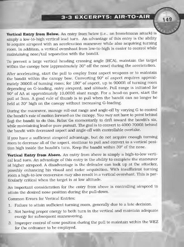
3-3 EXCERPTS: AIR-TO-AIR
Vertical Entry from Below. An entry from below (i.e., an Immelmann attack) is
simply a low-to-high vertical lead turn. An advantage of this entry is the ability
to acquire airspeed with an acceleration maneuver while also acquiring turning
room. In addition, a vertical overshoot from low-to-high is easier to control while
maintaining nose/tail separation with the bandit.
To prevent a large vertical heading crossing angle (HCA), maintain the target
within the canopy bow (approximately 30° off the nose) during the acceleration.
After accelerating, start the pull to employ front aspect weapons or to maintain
the bandit within the canopy bow. Converting 90° of aspect requires approxi-
mately 3000ft of turning room; for 180° of aspect, up to 9000ft of turning room
depending on G-loading, entry airspeed, and altitude. Pull range is initiated for
90° of AA at approximately 10,000ft slant range. For a head-on pass, start the
pull at 3nm. A good rule of thumb is to pull when the bandit can no longer be
held at 30° high on the canopy without increasing G-loading.
During the maneuver, manage roll-out range and angle-off by varying G to control
the bandit’s rate of motion forward on the canopy. You may not have to point behind
(lag) the bandit to do this. Relax Gs momentarily to drift toward the bandit’s six,
while maintaining lead or pure pursuit. The goal is to convert to 4000-7000ft behind
the bandit with decreased aspect and angle-off with controllable overtake.
If you have a sufficient airspeed advantage, but do not acquire enough turning
room to decrease all of the aspect, continue to pull and convert to a vertical posi-
tion high inside the bandit’s turn. Keep the bandit within 30° of the nose.
Vertical Entry from Above. An entry from above is simply a high-to-low verti-
cal lead turn. An advantage of this entry is the ability to complete the maneuver
at higher airspeed. A disadvantage is the defender can look up at the attacker,
possibly enhancing his visual and radar acquisition. With insufficient turning
room a high-to-low conversion may also result in a vertical overshoot. This is par-
ticularly critical when the target is at low altitude.
An important consideration for the entry from above is controlling airspeed to
attain the desired nose position during the pull-down.
Common Errors for Vertical Entries:
1. Failure to attain sufficient turning room, generally due to a late decision.
2. Not having proper energy to both turn in the vertical and maintain adequate
energy for subsequent maneuvering.
3. Improper control of nose position during the pull to maintain within the WEZfor the ordnance to be employed.

MISSION PREP AND INGRESS/EGRESS
Air Combat Maneuvers (ACM)ACM uses coordinated (two-ship) application of BFM to kill, defend, or separate
from one or more bandits in a visual arena. ACM is the link between the inter-
cept phase and the egress phase of the mission.
Objectives
1. Develop proficiency in two-ship coordinated maneuvering.
2. Teach specific engaged and supporting fighter roles in a visual fight.
3. Effectively integrate crew responsibilities to execute offensive and defensive tasks.
4. Develop enhanced situation awareness. An F-15E is capable of rapid kills
from an offensive start. Consequently, the role of the supporting fighter is not
the same when the engaged fighter is offensive as when he is defensive. This
adjustment in priorities resulting from the other F-15E’s positioned advan-tage/disadvemtage requires focused, concentrated training in the visual envi-
ronment. There are four cornerstones to effective element emplojnnent: com-munications, formation integrity, flight discipline, and weapons employment.
Communications. Clear, concise communications are one cornerstone of effi-
cient element emplo)mient. Every pilot must be able to use correct comm at cor-
rect moments in the fight. Proficiency in communications is gained only by dally
application on eveiy sortie. The time to start trying to improve your comm is not
after the first “break right” call is made. The flight briefing should be a review of
planned comm procedures, highlighting individual responsibilities and the
words/phrases used to convey the most meaning as clearly as possible.
Full flight callsigns 2ire mandatory. Do not assume your flight is the only one onthat frequency. Random radio calls with no corresponding callsigns attached
serve only to heighten the anxiety of all aircraft on frequency and, at worst, maycause disastrous consequences. Callsigns allow noninvolved flights to “tune out”
your transmission while getting the attention of the people your message is
intended for. When using the radio, a clear, controlled voice level requires you to
have the words you need ready when you key the radio.
1. Directive and Informative Radio Transmissions. As part of a fighting team,you see situations develop quickly as you maneuver. As the bandit maneu-vers you have to communicate what you see in the most efficient way. As the
wlngman, you may have to tell lead what to do if you have tally and he doesnot. If your information is not critical, your radio call should be informative

wy
3-3 EXCERPTS: AIR-TO-AIR
and lead will use it to make decisions while malntEunlng control of the flight.
When the flight is definitely threatened, a directive transmission is called for.
a. Directive Transmissions. Directive radio transmissions must be prefaced
by the callsign of the aircraft being addressed, i.e., “Eagle One, break right!”
Directive transmissions assume not all flight members have the SA necessary
to perform maneuvers required to defeat the threat. After making the “Eagle
One, break right!” call. Eagle Two should first ensure Eagle One is doing what
was directed. Next, an informative call describing why a break right is
required helps Eagle One acquire a tally. The supporting fighter must con-
tinue to use directive transmissions until the engaged fighter calls tally and
can begin to effectively defend for himself.
b. Informative Trsmsmissions. Informative radio transmissions are normal-
ly prefaced by the callsign of the alrcreift doing the talking. The most impor-
tan t of the informative transmissions is the bandit call, by which one aircraft
attempts to get the other’s eyes on the bandit. The bandit call has been stan-
dardized into the following format, which should always be used;
1. Callsign i
2. Type aircraft, or bandit/bogey »8
3. Left or right (side of aircraft)‘
4. Clock position >*>'
5. High/low/level
6. Range
7. Amplifying remarks
2. Sample Radio Calls. Here is an example of a call in the above format: “Eagle
Two, bandit, right. 3, low, 2 miles, going away.” A modification of this format
is used to follow up a directive call if your teammate is under attack. Here is
an example: “Eagle One, break right. Bandit, right, 5, high, 9000 feet, clos-
ing!” In this case, the position of the bandit is described with respect to the
airplane under attack so he can get a tally and counter the threat. Often, a
descriptive radio call may be enhanced by including the word “continue” in
the initial call, that tells all flight members no additional action is required.
For example, “Eagle continue right. Two’s tally one, right, 2, high, 4 miles.”
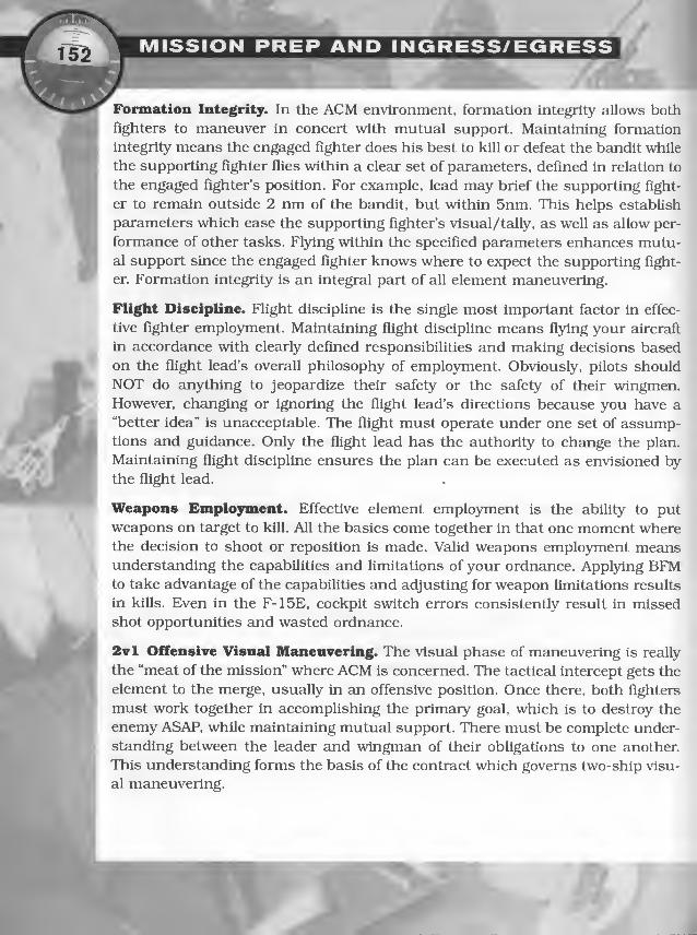
Formation Integrity. In the ACM environment, formation integrity allows both
fighters to maneuver in concert with mutual support. Maintaining formation
integrity means the engaged fighter does his best to kill or defeat the bandit while
the supporting fighter flies within a clear set of parameters, defined in relation to
the engaged fighter’s position. For example, lead may brief the supporting fight-
er to remciin outside 2 nm of the bandit, but within 5nm. This helps establish
parameters which ease the supporting fighter’s visual/tally, as well as allow per-
formance of other tasks. Fl5dng within the specified parameters enhances mutu-al support since the engaged fighter knows where to expect the supporting fight-
er. Formation integrity is an integral part of all element maneuvering.
Flight Discipline. Flight discipline is the single most important factor in effec-
tive fighter employment. Maintaining flight discipline means fl3dng your aircraft
in accordance with clearly defined responsibilities and making decisions based
on the flight lead’s overall philosophy of employment. Obviously, pilots should
NOT do anything to jeopardize their safety or the safety of their wingmen.However, changing or ignoring the flight lead’s directions because you have a
“better idea” is unacceptable. The flight must operate under one set of assump-tions and guidance. Only the flight lead has the authority to change the plan.
Maintaining flight discipline ensures the plan can be executed as envisioned by
the flight lead.
Weapons Employment. Effective element employment is the ability to put
weapons on target to kill. All the basics come together in that one moment wherethe decision to shoot or reposition is made. Valid weapons employment meansunderstanding the capabilities and limitations of your ordnance. Applying BFMto take advantage of the capabilities and adjusting for weapon limitations results
in kills. Even in the F-15E, cockpit switch errors consistently result in missed
shot opportunities and wasted ordnance.
2vl Offensive Visual Maneuvering. The visual phase of maneuvering is really
the “meat of the mission” where ACM is concerned. The tactical intercept gets the
element to the merge, usually in an offensive position. Once there, both fighters
must work together in accomplishing the primary goal, which is to destroy the
enemy ASAP, while maintaining mutual support. There must be complete under-
standing between the leader and wingman of their obligations to one another.
This understanding forms the basis of the contract which governs two-ship visu-
al maneuvering.

1. The Contract. Specific responsibilities must be assigned to each aircraft during
the engagement in order to take advantage of element capabilities. These respon-
sibilities serve two basic purposes: killing the bandit and ensuring element sur-
vival. Effective communication is vital to fulfilling each fighter s responsibilities.
There can be only ONE engaged fighter (either offensive or defensive) at one
time. Roles may rapidly change, several times, where the responsibilities must
be definitively handed off and confirmed with radio calls and aircraft maneu-
vers.
Engaged fighter responsibilities:
a. Maneuver to kill the bandit (offensive) or negate the threat (defensive)
in minimum time — fly best offensive/defensive BFM.
b. Clear the supporting fighter to engage if he is in a position to shoot and
the engaged fighter is safely outside the supporting fighter’s weapons field
of view (FOV) .
c. Keep the supporting fighter informed of intentions, capabilities, future
tactical plans, and if required, bandit position.
Supporting fighter responsibilities:
a. Maintain tally of the bandit amd a visual on the engaged fighter.
b. Clear for the element as the engaged fighter attacks.
c. Maintain energy and a position from which to employ ordnance (if
required), consistent with other priorities and without compromising the
engaged fighter’s safety. Do not become defensive.
d. Engage other bandits and advise engaged fighter of additional threats.
e. Direct defensive response as required.
f. Maintain overall SA (situational awareness) to include area orientation, fuel,
and separation opportunities.

The Flight Lead/Wingman Relationship. Hie previous discussion does not equate
engaged and supporting roles with leader and wingman positions: this is intention-
al. Current F- 15E tactics are designed to allow the best positioned fighter to engage.
On defense, the choice obviously belongs to the bandit, since whomever he attacks
is engaged. This, however, should not imply complete equality within the flight.
1.
The flight lead still has the ultimate responsibility for mission accomplish-
ment and flight survival.
2.
He makes the decisions about whether or not to engage, what tactics will be
used, and who will do the engaging or separating.
3.
While the wingman is engaged, the flight lead supports him but retains the
authority to direct the engagement, to terminate the engagement, to assumethe engaged role, or to revert his wingman to the supporting role.
J
The engaged/supporting responsibilities work effectively in most 2vl situations: how-
ever, when the contract breaks down, the flight may present a danger to itself
Confusion of roles is the most common problem. Two fighters, each thinking they are
A engaged, can easily end up occup)dng the same airspace: therefore, wingmen are only
w allowed to assume the engaged role on attack when cleared by the flight lead. This
avoids confusion about responsibilities. If the tactics are being well executed, the leader
should have to make very few inputs: when SA or proper execution break down, he
must take firm, directive control of the flight to ensure safe mission accomplishment.
Offensive Maneuvering. The termination of the intercept phase is when the engaged
fighter visually acquires and maneuvers against the bandit. If the bandit detects your
attack and maneuvers against you, the tactical wingman may be in a better position
to engage by virtue of turning room or because the bandit is actively attacking him.
As soon as possible, designate one engaged and one supporting fighter. TTiat occurs
when one fighter calls “Eagle One engaged, MiG-21, left, 10, low, 2 miles.”
1. Engaged Fighter. This fighter’s maneuvering is simply his best Ivl BFM to kill
the bandit. He should maneuver as aggressively as if he had no wingman, andshould not rely on his wingman to get him out of trouble. If the bandit cannot
be killed immediately, press the attack to remain offensive and force the bandit
to react defensively until your supporting fighter is able to maneuver for an entry
or shot. When Informed that the supporting fighter has an entry opportunity or
is engaging, maneuver to set up the supporting position, clear the supporting
fighter to engage, and assume the supporting fighter responsibilities. If unable
to do so, then so state and ensure the supporting fighter acknowledges, thus
clarifying that he is still the supporting fighter.

2. Supporting Fighter. The supporting fighter must gain or maintain turning
room for an entry to the fight and pick up supporting fighter responsibilities:
maintaining/obtaining visual/tally and clearing the area. The bandit may
either break away from the supporting fighter or into him.
3. Fight Entries. The supporting fighter may need to engage the bandit in sev-
eral situations. Generally, these can be classified into two cases: (1) When the
engaged fighter becomes defensive, and (2) When the engaged fighter is in a
fight that may take a long time to resolve.
When an F-15E is engaged with an offensive position of advantage, the sup-
porting fighter should not be primarily concerned with entering a fight that
will soon be over. When the engaged fighter is defensive, the supporting fight-
er should place primaiy emphasis on entering the fight and killing the ban-
dit. Flying the supporting fighter profiles described above places you in an
excellent position for entry.
4. Engaging Other Threats. The supporting fighter’s job is to keep the engaged
fighter free to kill the bandit. In part, this means killing any bandit who may
become a factor to the fight. Often, the supporting fighter gets a tally on anoth-
er bandit looking for an entry on the engaged fighter. The supporting fighter
must engage this new threat and quickly kiU it before the engaged fighter is
forced to react. Radar contacts may present a threat as well. These contacts
must be analyzed in terms of their range and aspect in relation to the fight.
Normally, split criteria are briefed to give the supporting fighter a decision-
making aid on whether to engage this new threat or monitor/drop it.
5. Supporting Fighter PosiUons. The supporUng fighter’s position must allow
fulfillment of responsibilities as listed above. In addition, he must be able to
assume engaged fighter responsibilities if the situation dictates. In relation to
the fight, the supporting fighter should strive to stay between 2nm and 5nm
away until ready to engage. This range window keeps the supporting fighter
far enough away to deny the bandit a shot opportunity while allowing rela-
tively easy tally/visual. In addition, his flight path should keep the fight
between seven and ten o’clock or two and five o clock. Do not allow the fight
to drift to six o’clock or you will quickly extend beyond visual range. Pointing
at the fight is only good for ordnance employment or entry into the merge
when cleared by the engaged fighter.
6. Areas to Avoid. The supporUng fighter must avoid three areas: direcUy above,
directly below, and within 2nm of the fight while hying to look for an entry.

MISSION PREP AND INGRESS/EGRESS
Flying directly above the fight forces the supporting fighter to focus attention
on the fight geometry instead of clearing the area for other bandits. If an entry
is attempted, the supporting fighter must fit the turn into an already tight
and, most likely, slow turning fight. Although possible, this maneuver is very
difficult and often results in an overshoot because of the inability to slow
down enough in a very nose low attitude.
Entering directly from below the fight has many of the same problems. Trying
to enter the fight from within 2nm should be avoided as well. Inside 12,000
feet, the supporting fighter may not have the required turning room and Gavailable to employ ordnance. This causes (at best) rushed shots and (at
worst) missed opportunities to engage. Nominally, this is caused by the dif-
ferences in energy between the bandit and the supporting fighter. More dis-
tance allows the supporting fighter time to predict an entry and react to the
situation.
Fl)dng inside 12,000 feet may also allow the bandit opportunities to pause
and employ ordnance against you while the engaged fighter is maneuvering.
2vl Defensive Visual Maneuvering Considerations
1. When the flight finds itself under attack, the obvious concern is survival
(negating the bandit’s initial attack). Because seconds are critically impor-
tant, the flight must have some preplanned initial moves — actions that they
are very familiar with and have thoroughly practiced.
2. Once the initial attack has been negated, the immediate concern of the flight
should be to separate or go offensive. Reestablish visual and positional sup-
port and maintain tally on the bandit to be sure you are out of range. If the
separation is not going to achieve sufficient range, the element needs to con-
tinue defensive maneuvering to deny the bandit weapons parameters. Theelement should use chaff/flares as appropriate.
3. If it is apparent from the beginning that the flight cannot separate, the object
should be to sandwich the bandit for a kill or to force a separation. Engagedand supporting fighter tactics are now in order. In this case, however, the
bandit determines who is engaged (the one attacked): the other fighter then
maneuvers to bring ordnance to bear.
4. Once the roles have been established, conduct of the engagement is concep-
tually straightforward (though often physically difficult). Just as on the
offense, the engaged fighter must perform his best Ivl defensive maneuver-

I
ing, this time to negate the attack. The supporting fighter should predict the
bandit’s flight path and maneuver for a shot. The engaged fighter must fight
his best defensive fight: the supporting fighter may not succeed in his attack
(or may come under attack himself). The supporting fighter, in addition to
keeping visual/tally and predicting flight paths, must be concerned with con-
ducting a quality attack and getting a good quick shot. Do not assume that
the bandit sees the supporting fighter or any missiles fired. A bad shot maynot pull him off his attack. Do not take shots that put your wingman at risk,
i.e., in the missile’s FOV. Coordination between the fighters is essential: it
increases each other’s overall situation awareness. Information from the
engaged fighter about where he intends to take the fight help the supporting
fighter better predict flight path geometry.
5. If both fighters are tally, but blind, it is imperative that roles be established.
Positive communication and effective maneuvering must be accomplished by
both fighters to ensure friendly flight path deconfiiction. The flight lead is
ultimately responsible for establishing these roles, element survival, and
training rule compliance. References off the bandit and/or separate altitudes
to ensure deconfiiction help both fighters achieve the visual while increasing
SA.
The following is a communication example where Eagle Two is engaged defen-
sive and Eagle One is supporting from an offensive posture:
Eagle 2 “Eagle Two defensive, tally one, blind.”
Ekigle 1 “Roger, Eagle One tally one, blind, offensive 1 mile behind the bandit.
E^agle One will stay high.”
Eagle 2 “Eagle Two is passing the bandit low, left to left, now.”
Eagle 1 “Eagle One, visual, your left ten o’clock high.”
Eagle 2 “Eagle Two, vlsueil.”
Ekigle 1 “Roger, Fox 2, kill, bugout South.”
Note: Specific verbiage may vary as roles/situations dictate.
r

'V*
MISSION PREP AND INGRESS/EGRESS-V
Initial Moves. The basis of successful two-ship defense is a system of well
thought out initial moves. The moves must effectively negate the initial attack.
They must be aggressive and designed to rotate the vulnerable cones away from
the threat. There is no room for error, so initial moves must be simple and easy
to remember. Lastly, initial moves must become almost second nature; only prac-
tice helps there. The main principles to follow in accomplishing initial moves
when the bandit is sighted in the aft quadrant approaching missile range are:
1. When defensive, avoid putting both aircraft in the same area at the same
time. When possible, split the element laterally and vertlcedly.
2. The aircrew with the tally should:
a. Start a hard/break turn into the bandit.
b. Call the flight left or right.
c. Dispense chaff amd flares.
d. Put lift vector on the bandit and pull.
Note: The first three items should be accomplished simultaneously.
3. The aircrew without a tally should:
a. Turn in the direction called.
b. Dispense chaff and flares.
c. Pull maximum Gs.
d. Attempt to acquire a tally.
4. The difference between a hard and break turn is power selection and G-load-
ing. In both cases, turn the aircraift to rotate your vulnerable cone while
bringing the threat to your nose. A hard turn should be called for if a bandit
has not reached weapons parameters but is mcmeuvering for a shot. Max ABin a hard turn assures maximum energy in the turn and after roll-out facing
the threat. If the bandit is in position to shoot or has taken a shot, a break
turn in MIL power or less while dispensing chaff and flares offers the best
defense. Afterburner should be selected as soon as the bandit’s nose is no
longer in position to shoot, or he is outside valid parameters. If it is evident
that the bandit intends to pursue the attack, stores Jettison may be appro-
priate, if so configured.

InterceptsAn intercept is the means by which a fighter aircraft maneuvers from beyond
visual range to a position to employ ordnance, visually identify the target, and/or
enter the visual fight arena. The intercept can be flown using GCI/AWACS infor-
mation, on-board radar information, or a combination of the two.
Prior to initiating any Intercept, consider the mission, threat, environment,
weapons load, ROE (rules of engagement), available support assets, and the pro-
ficiency of individual flight members.
Intercept TypesThere are two basic types of intercepts, and a variation which combines the ele-
ments of both. First is the cutoff or collision course intercept. This is generally
used where minimum time to kill is desired. The other is the stern conversion,
used when other limitations preclude a cutoff or identification may be required.
The two together form the front-stern reattack where turning room is maintained
or developed to allow a stern conversion should the AlM-7 attack fall or there is
a requirement to convert on the bandit.
Catofi/CoUision Course Intercept. The cutoff or collision course intercept is the
quickest course to weapons employment and is also the simplest of all intercepts.
To fly a collision course intercept, determine the CATA (collision antenna train
angle). The formula for a co-speed CATA is listed below. Turn to place the target
on the CATA.
180° - Aspect angle = CATA
Stem Conversion. The objective of a stern conversion is to develop and main-
tain turning room and close to a VID (visual identification) and/or firing position.
There are three types of stem conversions: horizontal, combination, and vertical.
1. Horizontal Intercept. The horizontal intercept is flovm nearly level with the
target and offers some advantages. Since the intercept is basically two-
dimensional, it is easier to track a target with no lock-on, and is easier to fly
during night or IMC (instmment meteorological conditions) conditions.
However, there some disadvantages. The fighter is easier to see and defeat
because he is level with the target. Also, the horizontal intercept requires a
lot of turning room (8-lOnm).

A MISSION PREP AND INGRESS/EGRESS
2. Combination Intercept. Combination intercepts gain turning room in both
the horizontal and vertical and can be thought of as either the chandelle or
the slice. Unlike the horizontal intercept, the combination gets the fighter
away from the target’s horizon and is therefore harder to see and to counter.
The main disadvantage is that night or IMC combination intercepts may not
be practical due to the maneuvering required (5-10,000 feet of vertical turn-
ing room).
3. Vertical Intercept. There are two types of vertical intercepts: low to high and
high to low. A key advantage to the vertical intercept is that it is very hard to
be seen by the target. Additionally, attacking from high allows entering the
fight with maximum energy advantage, while attacking from below may maskyour aircraft from the target's radar. The disadvantages are: difficult to get a
tally looking high to low, potential square corner (high to low), energy is eas-
ily depleted on a low to high (negative Vc (velocity of closure)), and it is very
difficult to fly no lock-on. The parameters are: more than 10,000 feet vertical
offset, early tally (8-lOnm), pure pursuit conversion at 30° antenna eleva-
tion/depression, and a rollout within 9000ft with 50 to 100 knots Vc.
During the vertical intercept, increase aspect to as close to a pure 180 as pos-
sible and achieve the desired vertical offset. At a minimum, fly the CATA until
reaching 30° elevation/depression, then pure pursuit. On a high to low,
power is modulated to control energy at roll-out. On a low to high, throttles
are in afterburner, maintaining energy.
Intercept SummaryThere are two basic types of intercepts: cutoff/collision course intercept, and
stern conversion. The collision course intercept is the easier of the two but it also
makes up a portion of each stern conversion. The table on the next page sum-
marizes the three types of stern conversions flown.

Aspect Angle Intercept Geometry Altitude Differential Pure Pursuit
Horizontal
H-16 Put target cold to
build turning room
40-50
Deconflict ±2000 ft 20nm& 15AA
15nm& 14AA
10-12nm& 13AA
15-12 CATA to maintain
turning room or hot
to increase AA
Deconflict ±2000 ft 20nm& 15AA
15nm& 14 AA
10-12nm& 13-12 AA
11-7 Put target 50-55 hot
to gain closure
Deconflict ±2000 ft 5-1Onm
6-T 1/2AA hot Deconflict 5nm
Combination
H-16 Put target on CATA
or cold to build
turning room 30-50
' 5-10,000 feet 20nm& 16AA
15 run & 15 AA
10nm& 14 AA
15-12 CATA to maintain
turning room or hot
to Increase AA
5-10,000 feet 15nm& 15AA
10-12nm&14AA
11-7 Put target 50-55 hot
to gain closure
5-10,000 feet 5-1Onm
6-T 1/2 AA, hot side 5-10,000 feet 5nm
Vertical
H-16 CATA/increase AA to H 10-15,000 feet 30° antenna elevation
15-12 CATA to conversion
point
10-15,000 feet 30° antenna elevation
11-7 Put target 50-55 hot
to gain closure
10-15,000 feet 5-1Onm and
30° antenna elevation
‘a
& T

MSt

AIR-TO-GROUND
COMBAT

TIPS ON USINGA/G WEAPONSStrike missions are the F-15E’s reason for being. So, it stands to reason that in
order to succeed in F-15 missions, you can’t know enough about when to load
and how to use all types of air-ground ordnance that the F-15E carries. To this
end, this section provides a compilation of tips for using weapons and bombing
modes, which we’ve gathered from playtesters and our own experience.
Quick Index of Weapon InformationYou’ll And information on air-to-ground weapons everywhere in this book.
O Tips. If you want tips on effectively using your weapons, look no further —Tips on Using A/G Weapons has advice gathered from pla3desters.
O Step'by-step instructions. If you’re still learning to use these weapons, see
the step-by-step instructions in the Expert Flight Manual on pp. 4.62-69.
O Fl3rthroughs. You will find detailed flythroughs of the game’s three air-to-
ground training missions — A/G Strafing, Guided Munitions and Unguided
Munitions — on pp. 22-27 of the Training Missions chapter. See also
Mission Types, pp. 46-97.
O Loadout advice. The game’s Arming screen has a Weapon Advisor function,
which tells you which weapons work best against different target. This info is
summarized in Weapon Advisor, p. 209. Combat: Engaging (Expert Flight
Manual, pp. 4.62-69) also discusses weapon selection considerations.
O Technical info. Jane’s entries for these weapons have more technical infor-
mation (full entries and 3-D views are aveiilable from the game’s Reference
screen: for abridged entries and diagrams, see Jane’s Speciflcations,
p. 262).
O Game stats. See Weapons, p. 224, for stats on all A/G ordnance.
O Delivery t]^e information. The 3-3 Excerpts: Air-to-Ground section
(pp. 176-195) of the Air-to-Ground Combat chapter gives real-world infor-
j', mation on A/G combat deliveries used by F-15E pilots.
fK-.

TIPS ON USING A/G WEAPONS
^-Ground MissilesThe only air-to-ground missiles in the game are the AGM-65D/G Mavericks.
AGM-65 MaverickO Although the AGM-65 doesn’t boast a very powerful warhead, it is idezd for
striking tanks and small buildings, especially if you don’t want to damage
adjacent objects.
O The game lets you choose between D- and G-models. You can carry up to six
AGM-65DS (lighter warheads) or two AGM-65Gs (heavier warheads). The D-
model is good for standoff, precision attacks against vehicles, SAMs, AAA and
small ships. The G-model is capable of the same, and it has a larger warhead
that allows it to destroy larger targets.
O AGM-65GS are a bit more rare in the game’s campaigns due to their sheer
size and cost per unit. However, a single AGM-65G can take out a small
building — it has roughly the same explosive power as a Mk 82.
O By default, the AGM-65s are set to Auto mode, in which the seeker head will
automatically lock on to a target when you designate one. If you switch to
Man (manual) mode (by pressing PB 6 on the Weapon Video MPD page), you
can use the IR video to center the missile optically on the target. This is more
difficult, however.
With all guided weapons, it can be useful to reprogram your right MPDs in
A/G master mode based on weapons you use the most. For instance, you can
preset the right MPD to default to the Weapon Video MPD instead of the A/G
Arm MPD. (Many playtesters recommend this.) See 6. Master Mode
Programming on p. 2.37 of the Expert Flight Manual
O When you select Mavericks, you normally select a single pylon. If you fire off
several missiles in succession, they all launch from the pylon you’ve select-
ed. Once it’s empty, you must then select the other AGM pylon in the Weapon
MPD. To avoid having to pause and do this, you can select both agm push-
buttons at once. Now, you won’t have to pause to activate the other pylon
once you run out of missiles on the first pylon.
0>"I

In order to successfully release any bomb, you must successfully complete two
tasks (in addition to simply staying alive, of course). Your first task is to steer
your aircraft so that you keep to a direct path over your target. Your second task
is to release the weapons at the right time so that they fall on the target. Guided
bombs that are steered after launch (i.e., Paveways and, if you are using a
datalink pod, GBU-15s) can correct for small errors made in either task, but
since the bombs have no propulsion system, corrections are limited.
Bombing ModesBombing modes control how the HUD presents the information you need to com-
plete your two tasks. Three different bombing modes are available. All three have
their advantages and disadvantages, which are discussed below.
Note: When you’re in A/G master mode, the current bombing mode is listed in the
lower right comer ofthe HUD. PBS oftheA/GArmMPD page cycles through modes.
CDIPO The default bombing mode — CDIP— often isn’t the best one. CDIP bombing
mode draws a line on the HUD from the velocity vector on your HUD down to
the point on the ground where the weapon will impact. The point of impact is
marked by a large reticle— you drop the weapon when the reticle is centered
over the target.
A problem arises ifyou are flying at a low altitude or flying slow— the weapon
,impact point is now closer to your aircraft, and the reticle disappears below
the HUD field of view. You can’t make an accurate drop if you can’t see the
O At low altitudes and low speeds, you are forced to make a dive-bomb attack
k^ on a target. Dive-bombing at low altitudes isn’t recommended — the most
common mistake made using CDIP mode is diving, then pulling up too late.
O At high speeds and with enough altitude, you can use CDIP mode for a near-
ly level delivery.
O CDIP can be inaccurate over uneven terrain because it uses the aircraft’s cur-
rent altitude to determine the altitude of the target.

Auto
O In Auto bombing mode a long, vertical line (ASL) extends up from the target.
You simply center this line on the HUD to align for an accurate pass over the
target. You should be able to see the ASL even when the target is beneath you.
O The weapons system controls when the weapon is released, so you can con-
centrate on steering and dropping countermeasures. When the TREL count
(lower right corner of HUD) reaches 5 seconds, pickle (i.e., press and hold joy-
stick button 2). Hold the pickle button down, and the weapon is automaU-
cally released when TREL reaches zero.
O Auto bombing mode can save you from yourself— if you’ve steered more than
20° to the left or right of your target, you won’t be able to release a weapon.
0 Auto is the best bombing mode for making level deliveries at 10,000ft or so,
but you can go higher or lower. Keep in mind that the higher your altitude,
the more margin there is for error.
Auto Loft
O Auto Loft mode is best applied to low-level bombing runs. You can come in
low (hopefully undetected), but pull up sharply before launch. Pulling up, or
“lofting” the bomb, gives it greater range than it would have if dropped from
level flight and removes you from the blast radius of the weapon.
O Mastering this mode is more difficult than the other two because;
1 . You have to fly precariously close to the ground. SAMs aren t a threat, but
AAA and unexpected terrain features are.
2. At high speeds and low altitudes, the time for finding and lining up with
your target greatly diminishes.
3. You must pull up at precisely the right instant. Time-to-pull (TPULL)
appears in the lower right of the HUD when you are in Auto Loft bomb-
ing mode. As soon as TPULL reaches zero, pull up. A horizontal line
appears on the HUD to indicate how far — pull unUl it is centered on the
velocity vector.
O Pickle after you start pulling up. As with Auto bombing mode, the weapon is
released automatically if you keep the button pressed until TREL reaches zero.

Release Mode Hints
O Auto and Auto Loft release modes are blind, meaning that you often can’t seethe weapons impact point or the target at the moment of release. In bothmodes, you must fly straight prior to releasing the weapon.
O In Auto mode, once you are aligned you can use autopilot to maintain yourheading and altitude. Make sure your wings are level, and press ®. Thenmaintain your altitude and press PB 9 on the UFC to get the Autopilot (a/p)submenu. Click PB 5 (alt hold). The autopilot will now maintain both yourheading and altitude. (Watch out for obstacles if you’re flying low, though.)
O In Auto Loft mode, watch the TPUL number (time to pull-out) number on theHUD. When it reaches zero, pull the nose up. Make sure, however, that youdon’t inadvertently bank the plane while you’re doing this. If you do, theweapon will loft wide of the target. Keep the pull-up steady, and when TREL(tlme-to-release) reaches five seconds, press the pickle button and hold it
down until the timer counts down to zero and all weapons release.
O In CDIP mode, start a gentle dive from 10,000 to 15,000 feet of altitude, andabout lOnm away from the target. Don’t angle down further than 45 degrees,or you’ll have trouble pulling up.
O In CDIP mode, the horizontal line that slides up and down the DIL indicatesthe edge of the frag envelope. At high altitudes, this isn’t very important.During low-level runs, however, make sure that this line is below the veloci-ty vector. Otherwise, your aircraft may get caught in the blast.

rTIPS ON USING A/G WEAPONS
7TW\,Dumb BombsDumb (ungulded) bombs may not be as accurate as their guided cousins, but
they are plentiful and fairly simple to use. You have a number of dumb bombs at
your disposal in F-15E. They can be divided into several types.
General Purpose, Low-Drag BombsO The Mk 82 and Mk 84 bombs are both unguided, general purpose bombs.
They can be dropped from any Eiltitude, although inaccuracies increase at
higher altitudes.
O Mk 82 and Mk 84 bombs are not especially effective against hardened tar-
gets, but they’re suitable for most other targets.
Cluster BombsO A cluster bomb looks like a normal bomb, but acts differently when it deto-
nates. Instead of impacting the ground, a CBU explodes at some predeter-
mined height above the surface and separates into smaller bomblets. These
bomblets can be incendiary (fire-starting) or fragmentary (explosive) and det-
onate upon impact with the ground. In the game, you can use the A/GArming screen to set the altitude at which detonation occurs.
O CBU bombs with fragmentation bomblets are intended for wide-area attacks
against soft targets, including troops, tents, grounded aircraft and other
un2irmored targets. Many different versions of CBU bombs are available. The
CBU-52, -58 and -71 carry fragmentation bomblets, while the “A” models of
the CBU-58 and -71 carry incendiary bomblets.
O The CBU-87 carries fragmentation bomblets as well, but each has a small
parachute which retards their flight. The CBU-97 bomblets have parachutes,
as well as small, individual IR-guided warheads.
O The Mk 20 Rockeye II is a cluster bomb, despite its moniker. It was the first
bomb of this type and is especially effective against tanks.

O You can use any high-powered bomb to crater a runway or taxiway. However,
the BLU-107 Durandal is specifically designed for penetrating this type of
surface. Its 15kg HE warhead imbeds itself over 10 feet underground, then
detonation occurs. This explosion below the surface causes much more
destruction than a normal surface explosion and takes more time to repair.
O In the real world, detonatiort can be delayed by minutes, or even hours. In
the game, detonation occurs several moments after impact.
High-Drag BombsO During low-altitude bombing, a bomb blast can pose danger to the attacking
aircraft. High-drag bombs attempt to solve this problem by attaching small
retard parachutes to the bomb, slowing its forward momentum and descent
rate. The aircraft can then safely pull up or speed away without getting
caught in the explosion.
O The BSU-49 (Mk 82 AIR) is basically a Mk 82 fitted with a retard parachute,
while the BSU-50 (Mk 84 AIR) is a Mk 84 with a similar parachute. Both are
intended for low-altitude bombing runs.

Guided BombsIt’s a bit more difficult to score a hit with a guided bomb. F-15 features two main
types of guided bombs — TV-guided GBU-15s and laser-guided Paveways.
GBU-15 (TV- or IRTV-Guided)O You can only carry two of these, but they pack a punch and almost always
hit their mark if you drop them correctly.
O In fact, the biggest problem with GBU-15s is that they’re in limited supply in
the game’s campaigns. You’ll probably want to conserve them for bombing
runs against a single, specific target.
O Within the GBU-15 family, there are four models:
• GBU-15(V)-1 A Mk 84 warhead with a TV camera for guidance
• GBU-15(V)-2 Same as - 1. with an IR camera to allow night use
• GBU-15(V)-31 a penetrator BLU-109 warhead with a TV camera
• GBU-15(V)-32 Same as -31. except that it has an IR camera
O Use the -1 and -2 against non-hardened targets or in areas where you want
to invoke a lot of collateral damage. Use the -31 and -32 against hardened
targets.
O All can be used during daylight hours, but only the -2 and -32 can be
dropped at night.
Dropping a GBU-15O Aiming a GBU-15 is much like aiming an AGM-65 missile, as long as you’re
using the Auto launch mode (as with the AGM-65. this is the default mode).
When you designate an air-to-ground target, the weapon’s seeker head will
automatically be aimed at this target. Weapon video from a camera in the
missile’s nose is displayed in the Weapon Video MPD.
O Pickle the bomb (i.e.. press button 2 on the Joystick) when the target is inside
the min/max range timers on the right side of the Weapon Video MPD or any-
time after TREL has expired on the HUD.

o Again, as with the AGM-65, you can press PB 5 (Manual) ifyou want to man-ually aim the weapon at the target before launch.
O However, the GBU-15 has an added feature which you cem use if you load an
AN/AXQ-14 (this is a two-way datalink pod, which is different from the
AN/AAQ-14 targeting pod). This pod allows to steer the weapon after launch
(using the video images on the Weapon Video page to see where it’s headed)
for maximum accuracy.
This can be fun, but it’s extremely difficult to do when you’re also trying to pilot the
plane and avoid AAA fire. (For instructions, see the Elpqjert Flight Manual p. 4.67).
O A good trick for dropping GBU-15s is to remain in Auto mode until after the
camera head snaps to target. Then, make the switch to Manual mode andsweeten the missile’s aim by using the arrow pushbuttons on the WeaponVideo MPD to center camera (and thus the nose of the missile) on the target.
Remember, you must activate tracking (trk) and switch to TERM mode for the
bomb to guide towards the target.
O If you’re using Manual launch mode, you’U really want to teike advantage of
the pause feature. That way, you manipulate MPD information while the
world around you is paused.
O The Weapon Video MPD functions with weapons that have video cameras
(GBU-lSs eind the AGM-65D Mavericks). It gives you a pre-launch view of the
weapon’s target. Simply left-click the arrow pushbuttons to maneuver the
camera view, then left-click the trk pushbutton. (See the E^ert Fl^ht
Manual p. 4.66, for details.)

TIPS ON USING A/G WEAPONS
Laser-Guided Bombs (aka Paveways)
GBU-10 (Mk 84 warhead)
GBU-10E Paveway II (Mk 84 warhead)
GBU-10G Paveway II (BLU-109 warhead)
O You can carry up to five GBU-lOEs for a short-range bombing run against
smaller targets. However. E-models incur a lot of drag if you’re playing in
Expert mode.
O The GBU-IOG features a BLU penetrator warhead, making it an ideal choice
for runway destruction.
GBU-12 Paveway I (Mk 82 warhead)
GBU-12D Paveway II (Mk 82 warhead)
O Two versions of this bomb., exists — the GBU-12 Paveway 1 and GBU-12D
Paveway II. You can ceury up to eight of either bomb.
O Neither bomb can take out a runway, but both are effective against small,
clustered targets and tanks. (You must hit targets head on to destroy them,
but with laser guidance, this isn’t too difficult.) If skillfully used. GBU-12/Ds
can be as effective as Mavericks — but much less expensive.
O GBU-12S are sometimes referred to as “tank-plinking” bombs.
GBU-24 Paveway III (Mk 84 warhead)
GBU-24D Paveway III (BLU-109 warhead)
O The GBU-24 and GBU-24A have a larger warhead than the -12. The GBU-
24D features a penetrating warhead that can puncture hardened targets.
O You can carry three GBU-24s (any model) — one under each wing, and one
on the centerline pod.
GBU-28 (BLU-113 warhead)
O This is the most feared bomb in the GBU family, but unfortunately, you can
only cany two of them on your aircraft. Known as a “Super Bunker Buster,”
it has a penetrating warhead and intense explosive power.

Dropping Laser-Guided BombsO When dropping a laser-guided bomb, you steer your aircraft into the target
area and release on the WSO’s cue, as you would with unguided bombs. After
release, however, you must activate the laser to guide them.
The first rule to live by then, is — don’tforget to load the AN/AAQ-14 target-
ing pod, which houses the laser designator. Without it, your valuable
Paveways won’t be anything more than expensive dumb bombs.
O GBU bombs don’t have propellant systems, so you need to give them momen-tum and room to maneuver. You can make a comfortable launch if you have
around 20,000 feet of altitude and an airspeed between 400 and 500 knots.
O You’ll probably find it easier to keep a level flight delivery if you use Auto
bombing mode (press PB 5 on the A/G Arm page until it says auto.)
O In Auto bombing mode, remember to keep an eye on the time-to-release
(trel) in the lower right corner of the HUD. Press the pickle button (weapon
firing button) down when TREL reaches 5 seconds and hold it until TRELreaches zero. (If you’ve selected more than one bomb for release, keep the
button pressed until TREL for the final weapon reaches zero.)
O Don’t activate the laser before you drop the bomb. After you release the
bomb(s), time-to-target (tgt) replaces the time-to-release (trel) on the HUD.
O Be careful not to activate the laser too early. The laser-seeker mechanism in
the nose of a Paveway “guides” the weapon by steering the weapon so that its
trajectory is aligned with the laser beam. Since the laser beam is a straight
line, and the natural trajectory of a bomb is an arc, if you activate the laser
too early, the Paveway ends up correcting and recorrecting it’s flight path
multiple times. These multiple corrections cause it to travel farther than nec-
essary, and it usually falls short of the target.

O Watch what you’re doing while you’re lasing the target. One drawback to
using laser-guided bombs is that you can’t make a sharp maneuver to avoid
SAMs or AAA fire while lasing the target. If you do so, you risk masking the
laser — putting part of your plane or a terrain feature between the laser and
the target you are lasing. If you do this, the bomb basically becomes an
unguided weapon, following a free-fall trajectory that usually ends up hitting
long.
O De-activate the laser after impact.
O When you pull up the Target IR MPD page in order to activate the laser, you
may discover that your designation was a little off. Fear not — you can use
the Target IR camera to fine-tune your target designation;
• To get a better view of the target, use PB 7 to cycle through field-of-view
options — WFOV (wide field of view), nfov (narrow field of view), and enfov
(enhanced field of view). WFOV covers the largest area, ENFOV gives you
the maximum magnification.
• Click PB 10 (trk) to deselect/unbox the tracking option. When TRK is
deselected you can move the camera about freely.
• Use the arrow pushbuttons (pbs 3, 8, 13 and 18) to center the tracking
gate over the target. Click trk again to snap the camera to the target. Now.
whenever you maneuver, the camera will move to keep this target in sight.
(As long as you keep the target where the Target IR can swivel to it, of
course.)
• Click PB 1 (CDEs) until cdes is boxed/selected. This redesignates the point
in the center of the tracking gate as your target. (If cdes was already
boxed, then the target was automatically redesignated when you clicked
the TRK PB.)
O Buildings are more difficult to crack if they’re hardened. The penetrator ver-
sions of the GBU (the -lOG and the -2 and -32 models of the GBU-15 and
GBU-24 A) work best against these targets. First, they pierce the target’s
outer concrete and make a nice, neat hole. Once past the concrete, they det-
onate. You can easily destroy a single, hardened target this way, but you
won’t score any collateral damage. Non-penetrator GBUs are not especially
effective against hardened targets.

man \ ,'
‘ y jf ^
^-3 EXCERPTS:» AIR-TO-GROUND
A thorough understanding of all available weaponry is an integral prerequisite to
a successful mission, but it isn’t the only thing you need to know. An F- 1 5E pilot
must be aware of all the factors that can come into play during a bombing run.
The following excerpts from the USAF 3-3 manned provide factual information
important in air-to-surface missions, as well as elements that need to be con-
sidered in the preparation stage.
All material in this section appears thanks to the United States Air Force
(ACCM/PACAFW USAF EW 3-3, Volume XVII, published I June 1994). Chapter
numbers and headings correspond to the numbers used in that manual.
I
Introduction^
Surface attack is the primary mission of the F-15E. With its long range, ordnance
carriage capability, night/lMC low-level capability, the F-15E is the most capa-
ble, flexible, and lethal long-range interdiction weapons system in the world. This
chapter presents the fundamentals of surface attack planning and execution, as
they relate to two employment arenas: the controlled range and the uncontrolled
range or battlefield, conducting tactical employment with live weapons.
Items common to all surface attack sorties include:
176 1
1. Desired mission objectives
2. Threats
3. Weather
4. Terrain
7. Tactical deception
8. Formations
9. Fuel
10. Communications
Ordnance load 1 1 . Support forces
6 . Weapons employment data*
* Including weather/lR detection range and systems back-ups.
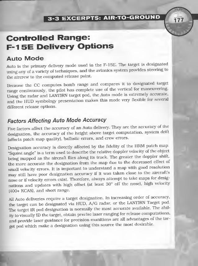
Controlled Range:F- 1 5E Delivery Options
Auto ModeAuto is the primaiy delivery mode used in the F-15E. The target is designated
using any of a variety of techniques, and the avionics system provides steering to
the aircrew to the computed release point.
Because the CC computes bomb range and compares it to designated target
range continuously, the pilot has complete use of the vertical for maneuvering.
Using the radar and LANTIRN target pod. the Auto mode is ejctremely accurate,
and the HUD symbology presentation makes this mode veiy flexible for several
different release options.
Factors Affecting Auto Mode Accuracy
Five factors affect the accuracy of an Auto delivery. They are the accuracy of the
designation, the accuracy of the height above target computation, system drift
(affects patch map quality), ballistic errors, and crew errors.
Designation accuracy is directly affected by the fidelity of the HRM patch map.
“Squint angle” is a term used to describe the relative doppler velocity of the object
being mapped as the aircraft flies along its track. The greater the doppler shift,
the more accurate the designation from the map due to the decreased effect of
small velocity errors. It is important to understand a map with good resolution
may still have poor designation accuracy if it was taken close to the aircraft s
nose or if velocity errors exist. Therefore, always attempt to take maps for desig-
nations and updates with high offset (at least 30° off the nose), high velocity
(400+ KCAS). and short range.
All Auto deliveries require a target designation. In increasing order of accuracy,
the target can be designated via HUD, A/G radar, or the LANTIRN Target pod.
The target IR pod designation is normally the most accurate available. The abil-
ity to visually ID the target, obtain precise laser ranging for release computations,
and provide laser guidance for precision munitions are all advantages of the tar-
get pod which make a designation using this source the most desirable.

AIR-TO-GROUND COMBAT
Auto Delivery TypesThe basic Auto deliveries — systems level, loft, and systems deliveries — zire
described in this section. Included are techniques to improve accuracy and crewcoordination.
Systems Level Deliveries (SLD)
A level attack profile provides an accurate means to deliver ordnance in all types
of weather. It is flown from the radar pattern on the controlled range. The figure
below is a depiction of the SLD profile. The approach to the target is from anyaltitude or direction. The attack steering is based on present position direct to
the tcirget or via a crew-selected attack heading if pattern steering is designated.
Once the target is designated, command heading on the HUD and HSI is the
heading to fly to reach the wind-corrected release point.
The primary task in tracking to the target is to keep the ASL centered. At 15 sec-
onds TREL, the radar automatically initiates AGR, if Auto is selected as the pri-
ority sensor (no laser ranging available). This is the pilot’s signal to concentrate
on keeping the velocity vector on the ASL and to stabilize airspeed and altitude
pcirameters.
The pickle button may be depressed any time after the target is designated, but
you may want to wait until you are at the desired release altitude with 5-10 sec-
onds TREL. After release, fly the safe escape maneuver used in planning the
delivery. Failure to do so may result in frag damage.

Loft Delivery
Loft is a low-altitude climbing delivery employed to achieve stand-off range with
low-drag weapons. After bomb release, a heird descending turn is accomplished
to get back to the low altitude arena and avoid overflight of the target and weapon
frag. The target may be designated by any means. Once A/G master mode is
selected, the HUD displays TPULL for the selected release angle with 5° or more
set for loft angle. Upon designation, the CC begins computing bomb range and
range to the target, and displays attack steering.
The approach to the target is made at low altitude on final attack heading. After
designating the target and selecting A/G master mode, azimuth steering is avail-
able via command heading and the ASL. In addition to range, the CC also com-
putes the time to reach the pull-up point to provide maximum range (or selec-
table angle) emd displays TPULL in the HUD data block.
Five seconds after pull-up begins, the CC checks to verify G-loading is 4 ± 1 and
climb angle has reached at least 15° to determine whether steering is being followed.
At ten seconds TREL, the release cue appears on the ASL above the velocity vec-
tor. When it reaches the velocity vector, if the pickle button is held down, the CC
generates the release pulse and the bomb is released. After the bombs are
released, roll to 120° of bank and pull the nose back down below the horizon with
4-5GS. Mter approximately 120° of turn, the target will be near 6 o’clock as the
roll-out generates maximum separation from weapon effects.
Loft Considerations. Because of the long TOF (time of flight/fall) for loft deliv-
eries, minor azimuth deviations may result in large impact errors. Fly the deliv-
ery at the planned parameters (airspeed, altitude, etc.) and pay particular atten-
tion to steering cues. The loft should be practiced as a night TF (terrain-follow-
ing) event.
The loft recovery is a self-inflicted
unusual attitude recovery, at
night, close to the ground. The
pilot should, however, fly the
egress so as not to mask the tar-
get prior to weapon impact, which
may require a less aggressive
recovery. If there is any doubt, go
through dry.
f

AIR-TO-GROUND COMBAT
CDIP ModeThe CDIP mode is a very accurate mode for visual bombing in the F-15E undermost conditions. The ability to manage the system improves bomb scores from
merely qualifying to outstanding. The CC accomplishes many of the tasks (wind
correction, gross weight/density altitude/AOA correction) required of the pilot
flying manual deliveries. The current bomb range computed by the CC is used to
display the HUD pipper at the point where the bomb will impact if pickled imme-diately. This technology advantage results in more accurate bombs, but can also
make pUots lazy about establishing parameters. Although the computer gets the
bombs on target, it does not necessarily provide a safety margin for frag clear-
ance, desired impact angles, fuze arm times, or burst altitude of weapons. Thecrew must plan for all these factors using specific release conditions, and the
pilot must strive to achieve the required parameters during the delivery.
Factors Affecting CDIP Accuracy
There are two groups of error in CDIP deliveries. These are trajectory and release
point errors and system management/ranging errors. The first group is con-
trolled by the pilot and can be minimized with good roll-in, track, and pickle
(parameters) techniques. The second involves knowledge of the system emd howit computes the bomb release solution, as well as controlling the system for the
best results.
If the pipper is not on the target at pickle, chances are the bomb will not hit the
target. Usually aiming error is due to poor roll-in and tracking technique, result-
ing is rushed and inaccurate pipper placement. Fly a smooth, consistent roll-in
and place the velocity vector long of the target. Hold the velocity vector on the
AOD with slight forward stick pressure while allowing the pipper to track
smoothly up the DIL to the target.
Timing of the pickle is critical to CDIP accuracy. Anticipate the arrival of the pip-
per over the target. Press and hold the pickle button down as the pipper covers
the target. Do not “quick pickle” as this may lead to a dry pass. If the pipper is
slightly right or left of the target, accept the error and do not attempt a last-sec-
ond correction, as you will invariably pickle long.

CDIP Delivery TypesAlthough there are several different types of CDIP deliveries, the simUanty of div-
ing deliveries allows discussion of them as being either level or diving.
Diving Delivery
The procedures and techniques for CDIP diving are similar for all release angles.
Climb to altitude and stabilize at the briefed airspeed. Use 3-4Gs to roll out at the
proper distance from the targets. Adjust airspeed and altitude to meet planned
parameters, and angle in or out if the base distance is wide or Ught. Set MIL
power, and smoothly roll and pull the nose toward the target with 100° to 120° of
bank and 3-4 Gs. As the nose drops, reduce bank angle to hold the planned dive
angle. Disregard the CDIP pipper initially, as this symbology is “buried” in the bot-
tom of the HUD. Fly the nose of the jet to a point long of the target.
During the 3-5 seconds of tracking time on final, trim or maintain slight forward
pressure on the stick to maintain dive angle and to slow the pipper tracking rate.
If the DIL is not centered on the target, make an immediate correction to get it
there. Then, use small smooth corrections to center up the DIL. Hold a shallow
bank angle to keep the DIL centered. Anticipate the arrival of the pipper on the
target. Approaching the release point, especially when flying low altitude/low
dive angle deliveries, the pipper tracking rate appears to increase. Do not com-
pound this problem by “pulling” the pipper early. Continue making small bank
corrections, but try to stabilize the aircraft for 1 second before pickle to allow the
pipper to stabilize.
Depress and hold the
pickle button until release
occurs.
•!
DISTANCE FROM AOP

Visual Level Bomb (VLB) Delivery
The CDIP delivery is normally a backup to an Auto level delivery, but is sometimespracticed intentionally. Fly no lower than the minimum release altitude based oncrew qualification or frag considerations for the best accuracy. Use caution to avoid
the common tendency to enter a slight dive approaching the target. Keep the DIL onthe target. Fly as wings-level as possible during the tracking phase. Anticipate the
arrival of the pipper over the target, and hold the button down.
Level Considerations. Transition to CDIP on a level pass is usually a back-up for
an Auto delivery, so briefwhen and how you will transition to CDIP in the crew brief-
ing. Consider setting a TREL minimum, such as 10 seconds, for the decision to
default to CDIP or go dry. Identify bad steering early to avoid large heading changes.
CDIP Error Analysis
Between passes, analyze the previous pass to determine what corrections, if any,
should be made on the next pass. Any deviation from the plarmed release para-
meters, errors in ballistics/mll setting calculation, or aiming error will result in
a miss. With a correct sight setting and the pipper on the target, the following
errors in a specific release parameter result in the listed impact error.
1Release Parameter Impact Error I
Dive Angle Shallow Short
Steep Long
Airspeed Slow Short
Fast Long
Altitude High Short
Low Long
Bank Short, laterally In the direction of the bank
G-Loading Pull Short
Bunt Long
Skid Laterally In the direction of the skid
Corrections. If you did not have the proper aim point, recompute and move it.
If the problem was tracking the aim point, resolve to track more accurately.
Ifyou had an error in parameters, the most likely problem is the base leg was not
properly flown. Improper base leg position can result in dive angle and altitude
errors. Roll-in technique is most often responsible for airspeed problems.

3-3 EXCERPTS: AIR-TO-GROUND
Mission PlanningWeaponeeringWhether you are planning a continuation training (CT) sortie or an actual com-
bat mission, the objective is still to inflict a certain level of damage on the
assigned target. This level is dictated by the ATO or frag, or is determined by the
flight lead using the joint munitions effectiveness manuals (JMEM), The JMEMs u.
describe the Pk (probability of kill) of various weapons against different type tar-
gets. Total or 100% destruction is usually desired, but this is difficult to achieve
without unlimited resources or expensive guided weapons. Your job when plan- ^nlng the mission is to attain the highest level of damage with the weapons pro- v
vided.
Considerations
Several factors to consider include: • «
1. Target— location, size, composition, coordinates, and photos.
2. Threats — location, type, numbers, status, and capability.
3. Force composition— flight size and support assets.
4. Weapons — gulded/dumb and numbers.
5. Delivery— target designation, weapons accuracy/effectiveness, radar/visual.
While a level delivery from medium altitude may maximize target radar acquisi-
tion and weapons effects, accuracy required for unguided weapons may force a
lower release altitude, and a standoff delivery such as a loft or LRDT may be
required due to target area defenses. The final attack profile will always be a com-
promise between exposure to the threat, delivery accuracy, and weapons
effects/target destrucUon. The flight lead must determine which decision factor
takes the highest priority on each particular mission.
,f_

>' -
AIR-TO-GROUND COMBAT
Attack Profile SelectionSome of the basic attack profiles are level, loft, dive toss, pops (offset pop anddirect pop), and systems deliveries. Basic characteristics, advantages, and dis-
advantages are detailed for each of the six profiles.
Level
This attack is usually conducted from low altitude, but is a viable medium alti-
tude delivery also. Advantages of the level attack profile include less maneuver-ing for ease of navigation and timing, capability to attack under a low ceiling,
reduced exposure to threats, and lower overall crew workload. Disadvantagesinclude weaponeerlng restrictions such as maximum altitude for fuze armingand weapons effects (impact angle), visual acquisition difficulty, straight-line
two-dimensional flight to the target — simplifying threat acquisition and track
of the friendly aircraft — and frag deconfiiction between formation members.Execution of the level attack from medium altitude decreases crew workload, butexposes the aircraft to other threat envelopes and greatly decreases unguidedweapons accuracy. Due to disadvantages of the level attack profile and the accu-racy of the F-15E using other profiles, it is usually the last choice, forced byweather, degraded systems, or weapon tactics restrictions.
Loft
This profile combines the standoff from frag and threat advantages of a mediumaltitude level delivery with the low exposure profile of a low altitude level attack.
Although visual acquisition is not a viable back-up for this delivery, with a goodtarget designation, the loft delivery can be as accurate as a level delivery with
F-15E avionics. Munitions such as proximity-fuzed CBUs can be delivered fromlow altitude using the loft maneuver, something not possible in a low altitude level
attack. Due to the standoff aspect of this delivery, frag clearance is not a factor for
attacking aircraft or wingmen, but maneuvering a two-ship during a loft attack
and egress can be complex. Disadvantages Include increased exposure to threat
envelopes, but this is partially negated by the three-dimensional maneuvering of
the profile and the standoff range from the target. Another disadvantage is the
level of aircrew workload required to accomplish this profile, especially at night.
Dive Toss
This delivery is a low altitude attack profile which combines standoff capability with
visual acquisition/designation benefits. Initially, the profile is flown like an offset
pop, but with a pull-up 2-3nm further away from the target. This results in a shal-
low dive to enable finding and designating the target with the HUD pipper or TDdiamond, followed by an Auto release and recovery outside threat ranges.
Advantages in addition to standoff from threats and frag include liberal tracking
parameters, positive visual ID of the target, and the abUity to designate the target
and then select a different attack axis. Disadvantages are similar to those for the
loft delivery, including task saturation, exposure to threats, difficulty in visual
acquisition from longer ranges, and less accuracy than a CDIP delivery.
Offset Pop
This low altitude profile is used to get the aircraft into a position to deliver low or
high drag weapons using a CDIP release with minimal exposure. High-drag
munitions can be delivered from a shallow (10°) dive with low release altitudes,
while low drag munitions require a 20°-30° dive and corresponding higher
release altitudes to satisfy all weapons effects, dive recovery, and frag clearance
requirements. A low altitude ingress is flown toward the target area. The aircraft
can be flown directly at the target and “actioned” left or right just prior to pull-
up, or can be flown directly to the pull-up point. At the pull-up point the aircraft
is flown at a steep climb angle with the target offset to the side for easier visual
acquisition. From a predetermined pull-down altitude, the aircraft is flown to
CDIP release parameters, then an escape maneuver is flown to avoid the frag and
return to low altitude.
Because the pilot uses a CDIP designation and minimum release range, this pro-
file is very accurate. The aggressive maneuvering in the pull-up, pull-down, and
escape maneuvers make the aircraft difficult to track, and exposure is planned
to be the minimum required. Formation mutual support is enhanced, as the
flight members in the pop are easily visible to those still at low altitude. With a
high enough release altitude, frag deconfliction is simplified, and severed aircraft
can attack the target in just a few seconds. This profile is not very flexible, how-
ever. It requires precise planning and execution, and is task-saturating, espe-
cially in multi-ship formations. A minor navigation error can place the aircraft
either well inside or outside planned attack parameters. During the tracking peri-
od, the aircraft must be flovm in a straight and level attitude (predictably) to
ensure accurate CDIP pipper placement.

This delivery adapts the pop-up attack to night LANTIRN operations. By using a
straight-ahead pull-up and pull-down (zero angle-off), no offset to the pull-up
point is required — just a range to the target. Using the N-F HUD display, the
pilot can confirm the target area visually at night, redesignate (if required) and
attack the target with Auto/CDIP. The direct pop is planned as a primary attack
or as a back-up to a loft. In most cases, however, the disadvantages make this a
delivery adapted to very few situations. For range to the target to accomplish the
maneuver, the pilot still requires an accurate designation. Unless a “bad” loft is
recognized before or right at pull-up initiation, a transition to a direct pop is dif-
ficult, if not impossible. The maneuver can be very disorienting, and there is a
potential for the pilot to misinterpret the HUD/ADl displays. First-look target
identification in the N-F is feasible only for large targets, such as buildings,
industrial complexes, or airfields. There may be situations, however, where the
direct pop gives the best combination of threat avoidance and target detection

L
A
3-3 EXCERPTS: AIR-TO-GROUND /
Systems Delivery
The above deliveries all use aircraft systems. An Auto delivery, using release
techniques similar to a dive toss or direct pop, is the normal release option, but
CDIP can be used with steep dive angles. Advantages of this maneuver Include
long track Ume, ability to redesignate using the HUD/N-F (if required), no terrain
masking during mapping, avoidance of the frag, ground, and small
arms/AAA/short range SAMS, additional time and airspace to
detect/evade/defeat SAMS, and overeill lower crew workload. Disadvantages of
this profile are greater exposure to AI (Air Intercept) and SAM threats, visual tar-
get ID difficulty, and degraded weapons accuracy, especially in cross-winds.
HRM PlanningAfter the low level route has been planned, it is important to select radar offset
aim points for system updates or target designation. To obtain usable HRM pre-
sentations without excessive maneuvering, several factors must be considered
during the cruise, low level, and attack phases of the mission.
Medium Altitude Cruise
A significant cultural or geographic feature should be selected as an update point
prior to the low level descent point to ensure all flight members have accurate
navigation capability prior to descent. Large bridges, airfields, or distinctive iso-
lated peaks are all good options. Select a point far enough left or right of the
planned route to allow straight-line navigation without check turns to obtain an
acceptable squint angle. Also, select points at sufficient range to maintain the
radar graze angle under 20°. At 20,000ft, the minimum range for this angle is
lOnm; therefore, plan to take the maps in the 15-25nm range.
Low Level Ingress
Select points to map which require the least maneuvering in heading and altitude,
as this will assist in avoiding detecUon. The best way to accomplish this is to select
points which move into a window of optimum mapping during straight-line navi-
gation. For squint angle considerations (which affect map quality and designation
accuracy), take the map at least 30° off the nose. Ensure time to get two maps prior
to radar gimbal limits by planning to cease mapping by 50°. The combination of
range to the point and aircraft altitude will affect map quality due to graze angle.

AIR-TO-GROUND COMBAT\r\
By planning the distance traveled between the squint angles of 30° ctnd 50°, you
can determine the amount of time available for mapping. Closer offsets result in
shorter available map time but higher graze angles. More distant points sacrifice
graze angle, but allow more available time for mapping. Tiy to select points which
offer the best combination of both factors.
Other factors to consider include intervening terrain which might mask the point,
or trees in the offset area. Either factor will require a climb to obtain an accept-
able map. Finally, coordinate mapping between flight members. The flight lead
will not want all members heads-down getting updates simultaneously with no
one monitoring the A/A radar or checking 6 o’clock.
Ground Clearance
The altitude lost during dive recovery is the vertical distance above the groundwhere the pilot must initiate the pull-out maneuver to ensure zero ground clear-
ance, as shown in the table below. A 5G, wings-level recovery attained in 2 sec-
onds is assumed. The desired ground clearance is added to the listed altitude lost
during dive recovery to get a minimum release altitude.
IDive Angle Altitude Lost I
10° 260 ft
15° 460 ft
20° 690 ft
30° 1380 ft
45° 2200 ft
Note: Sea level target, 500 KTAS. 5 Gs In 2 seconds pull-up assumed.
, if . Safe Escape and F-15E Avionicsr '
The F-15E HUD displays a “Frag Cue.” In situations where a frag cue is dis-
played, the cue represents the predicted frag envelope for whatever weapon is onboard and in priority. As long as escape maneuvering results in the velocity vec-
tor being above the frag cue at detonation, there should be no frag damage.
The CC does not compute a minimum ciltltude for Scife escape. This is the crew’s
responsibility and is accomplished only by reference to the safe escape
table(above) and the Dive Recovery chart (p. 204).

3-3 EXCERPTS: AIR-TO-GROUND
LOW-ALTITUDE OPERATIONSIntroductionThe F-15E is optimized to ingress and egress at low altitude both day and night.
Although the INS, TSD, TFR, and LANTIRN give very reliable low level capability,
crew proficiency is still the most critical aspect of low altitude operations. This
chapter discusses the following low altitude topics: awareness cind considera-
tions, and low-level navigation techniques.
Awareness And ConsiderationsAltitudeFly only as low as necessary to avoid the threat and optimize weapons employ-
ment. At some altitude, all pilots cease performing all tasks except terrain avoid-
ance. For this reason, more and more duties are delegated to the WSO as alti-
tude decreases, but the aircraft should not be flown lower than crew comfort
allows. If the WSO spends all his time checking 12 o’clock, you are too low. Fly
at an altitude that is comfortable to both crew members. Raise the minimum alti-
tude as task loading increases or when the tactical situation allows. In an emer-
gency or abnormal situation, climb immediately to a comfortable altitude.
AirspeedHigher airspeeds decrease the time exposed to a specific threat, but increase the
difficulty of maintaining desired alUtude. While terrain masking in rough terrain,
a slower airspeed (400-450 KCAS) may be required to keep the turn radii small
enough to stay in the canyon or hug terrain.
Threats and Terrain
Over relatively flat terrain, all threats have better low altitude capabilities. As ter-
rain gets rougher, the threat minimum altitude gets higher. Do not try to fly at
100 feet AGL if the terrain does not permit it or the threat does not require it.

Altitude ReferenceThe horizon and ground objects near the aircraft serve as the altitude reference.
The radar altimeter can assist in calibrating altitude awareness. It is relatively
easy to maintain desired altitude over terrain consisting of large ground objects
such as trees or rocks. However, as the size of the ground objects decrease, deter-
mining how high you are visually becomes more difficult. Most pilots have a
strong tendency to descend to lower than desired altitudes over flat, even terrain.
Very flat terrain or calm water is surprisingly dangerous because of a lack of depth
perception. Over flat terrain, it is easy to sink to a dangerously low altitude with-
out realizing it. Flat, sloping terrain is more hazardous because of the insidious
change in elevation as you fly into a gentle up-slope. Use the radar altimeter to
improve altitude awareness as the terrailn features change. In some extreme con-
ditions of flat, featureless terrain or water and poor visibility, the CARA (combined
altitude radar altimeter) becomes the primary source of altitude reference. Under
those conditions, consider engaging the TFR (terrain-finishing radar).
Ridge Line CrossingsCrossing ridge lines in high threat areas is a dangerous move. The aircraft is
highlighted to threats, both ground and air. Avoid ridge crossings if at all possi-
ble. Obviously, many situations force you to cross ridges. Accordingly, plan for
and practice good ridge crossing techniques. Three ridge crossing types are com-
monly employed.
Perpendicular
This crossing minimizes enemy radar or visued acquisition but should be done
only when you know your 6 o’clock is clear. Accelerate as required to maintain
tactical airspeed during the pull-up. Pull early enough to avoid a large overshoot
crossing the ridge, so you crest
the ridge at your specified mini-
mum low level altitude. To go
down the back side, bunt or roll
and pull. A totally inverted pull-
down is prohibited. At the crest,
unload Eind roll to approximately
120° of bank, then slice down. At
the desired nose low position.

roll-out and resume low level flight. Initial attempts at this technique should be
limited to a 15° nose low attitude. DO NOT bury the nose in the new vedley. This
maneuver may put you belly up to unexpected high terrain on the other side of the
mountain. Consider wing flash during the slice/pulldown; it is highly visible. The
roll and pull technique is most effective when crossing leirge, steep, isolated ridge
lines. A bunt or pushover is more appropriate for milder, rolling terrain. The adv8m-
tages of the bunt are straight line navigation, no wing flash, and less crew disori-
entation. Remember the zero-G transient and 10-second negative-G restrictions.
Parallel
This type of approach is appropri-
ate if your 6 o’clock is (or may be)
threatened. It denies the bandit a
blue-sky background and pro-
vides a difficult guns environ-
ment. Instead of a straight
approach to the ridge, turn to
arrive at the pull-up point with
approximately 45° of crossing
angle to the ridge. Pull up later
them for a perpendicular crossing, and continue to turn in the climb to be parallel
to the ridge crest just below the top. Roll and pull into the ridge, to cross the crest
at your specific minimum altitude. Continue a loaded roll to fly down the backside
of the ridge, on a heading 90-135° from the ridge line. Roll-out and continue the
low level.
Saddle
The saddle type ridge crossing is
similar to the parallel, £md can be
used when you are threatened.
Turn to parallel the ridge line
below the crest until you can use
a saddle, canyon, or the end of the
ridge to cross to the other side.
The exact maneuver is dictated by
terrain characteristics, but can be
as simple as a level 90° turn.

cause long shadows, and obscure terrain features. You can normally see the i
horizon but cannot see anything between you and the horizon due to shadow.*
This makes low altitude flight very difficult and visual target acquisition nearly )
impossible. The HUD may be unusable when fl5dng into the sun. If a navigation
leg must be flown into the sun, consider using the TFR and NAVFLIR.
Insidious DescentOne of the most dangerous aspects of low altitude flight is insidious, unplanned
descent into level terrain. The following data should help you understand the
cross-check required for very low altitude operations.
Wings-Level Shallow Dive
In wlngs-level flight at 300 ft, if the aircraft is in a 2° dive at 480 KTAS, time to
ground impact is 10.5 seconds. If the dive is not detected and recovery not initi-
ated within approximately eight seconds, ground impact is unavoidable. At lower
altitudes, these times decrease (e.g., at 100 ft, wlngs-level, 2° dive, 480 KTAS,
ground impact occurs in 3.5 seconds). Pull-out must be initiated within the first
second to avoid hitting the ground. See the table below for additional examples.

3-3 EXCERPTS: AIR-TO-GROUND
Low-Level Navigation
Low-Level PlanningFactors affecting route selection include the mission objective, threats, terrain,
weather, and vlsual/radar significance. The mission objective (target, desired
level of damage, etc.) has a significant impact on the attack plan.
Weaponeering
A requirement for specific attack aids can affect the desired routing to the teirget, ^so it is usually best to pick the IP (initial point) and plan the attack first. Then
plan the route to get to the IP and egress from the target.
Threats
Enemy threats are perhaps the greatest factor in low level route selection. Avoid
the threat when possible, and when necessary to fly through threat envelopes,
plan the route to degrade the threat’s capabilities. Current intelligence on the
location and movements of enemy units is essential.
Terrain
Where possible, use terrain features to mask the flight from threats and provide
tactical surprise in the target area. Avoid crossing ridge lines. When ridge lines
cannot be avoided, plan and execute crossing them.
Sensor Aim Point and Offset Selection
Plan for seversd update points along the low level. If two-ship or four-ship oper-
ations are planned, choose enough update points to allow for alternate updates
if threats, route adjustment, or other mission tasks prevent use of the primary
point. If flying in hilly terrain, the window of opportunity for mapping an update
point may be limited.
Visual Update Points
Consider planning at least one visual update point. Choose a point reasonably
close to the target area, to provide back-up weapon delivery capability in the
event the radar HRM mode is inoperative, terrain or threat reactions prevent get-
ting a HRM map, etc.
to

Night operations provide several advantages over less sophisticated enemies
including surprise, denial of visual acquisition, 24-hour operational capability,
and psychological impact. Although LANTIRN, the TSD, and other systems in the
F-15E make it an easy system to employ in the dark, night operations are always
more demanding and hazardous than day VMC (visual Meteorological conditions)
operations. Therefore, make some special considerations when conducting night-
time operations.
Night Flight PreparationFirst, check your personal equipment. Each crewmember should carry a flash-
light. Wear a clear helmet visor. Mission materials and lineup cards need to be
clearly marked and easily readable in a darkened cockpit. Consider taking tape
to cover undesired light sources. Familiarization with the location of critical cock-
pit switches is important.
Route PlanningEstablish MSAs (minimum safe altitudes) for the route. In most cases, good visu-
al tumpoints make good FLIR tumpolnts. The two ingredients of valid FUR turn-
points are IR contrast and vertical development. It is best to have both, but as a
rule, IR contrast is the most important. A point with vertical development not only
enhances FLIR acquisition, it is also more likely to be a radar show point. A point
which has good IR contrast, vertical development, and is radar significant makes
the ideal LANTIRN tumpolnt, IP, or target. Maximize terreiin masking, but plan the
route to avoid or minimize the effect of large terrain features on TF operations.

Intel SupportLANTIRN requirements for Intel can be broken into two broad areas:
Target Area Considerations. The quality of TDA(tactical decision aid) provided
depends on the accurate, detcdled definition of target Euid background charac-
teristics. The use of photography for TDA information and aircrew study sub-
stantially increases the probability of first pass success.
Target/Tumpoint Accuracy Requirements. At night, there is little capability to
take a quick glance to the left or right and see the turnpoint or target. The nav-
igation system must be accurate enough to center the FLIR/TGT IR FOV on the
target at the expected acquisition range. This roughly equates to a minimum sys-
tem accuracy of .2 to .3nm. Plot turnpoints to an accuracy of 100 feet in both the
horizontal and vertical.
A/A RadarA/A radar should be used to m8iintaln formation spacing at night. A good search
plan includes altitude coverage for the wlngmen which allows them to cross-
check other flight members occasionally. Avoid locking on to the preceding air-
craft unless absolutely necessary.
Display ManagementPlan this function before stepping to the aircraft. Because the ADI, TF, and other
“night” displays use scopes you employed for other displays in the da3dlme, plan
scrolling carefully. Consider programming only two displays per scope. This
allows you to “toggle” between displays, a technique some crews find easier to
manage. Have a plan if you end up flying with one display inoperative.
Minimum Essential Systems List
(MESL)Review this list for night/TFR (terrain-following radar) operations, and plan an
alternate mission if unable to fly the primary mission due to system problems.


/\ MECHANICS / .
r
OVERVIEWThis chapter contains charts, tables, lists and other information about the F-15E
cind the other aircraft you’ll encounter while playing the game. Some are taken
from the USAF F-15E instruction manuals. The rest are straight from the game.
F-15E Performance Includes charts and tables describing the F-15E’s flight char-
acteristics. When there isn’t a line on a chart that matches your current configu-
ration, make an estimate based on the two lines that bracket that configuration.
• Mach/Altitude/Speed (p. 199) charts relationships between current altitude, indicated airspeeds and Mach ratio.
• Time to Climb (p. 200) charts how long it will take to climb to a new altitude.
• Stall Speeds (p. 202) charts at what speeds your F-15 begins to stall.
• Dive Recovery/Emergency Pull-Out (p. 204) charts how far you will continue falling, after you begin to
pull out of a dive (whether planned or unplanned). It also includes a few basics of dive recovery.
• Cruise Efficiency (p. 206) lists how many nautical miles you'll get per pound of fuel, based on altitude and
drag index. It shows the most efficient altitudes for long-range cruising, along with the most efficient Mach.
• Combat Ceiling (p. 207) charts how high you can fly.
Player Aircraft Stats includes the numbers and other information you need to
customize your aircraft for einy specific mission.
• Weapon Advisor (p. 209) summarizes the game’s Weapon Advisor information.
• Drag index and Weight (p. 210) describes 6rag index, then lists the drag index and weight of every store
possible for your F-15E.
• Allowable Stations/Weapons (p. 21 2) lists which stations can mount which weapons and other stores.
• Ordnance (p. 214) briefly describes each of the weapons you have available.
• Fuel Quantities (p. 21 5) calculates how much fuel you can carry.
• Default Loadouts (p. 216) details the eight default loadouts available to you, then briefly analyzes the best
uses for each loadout.
Game Stats list all the crucial stats for everything else you’ll encounter in F-15.
• Aircraft (p. 222) lists everything about the other aircraft, except their loadouts.
• Weapons (p. 224) details the weapons you fly with, and fly against, in the game.
• Radars (p. 228) has all the crucial range and radar type information.
• Aircraft Loadouts (p. 230) lists every possible loadout you might encounter.
• Other Targets (p. 238) describes what you’ll find on the ground.
Damage System briefly describes the game’s complex damage system, giving you
the broad strokes of how damage is calculated, particularly for your own fighter.

F-15E PERFORMANCE
F-1 5E PERFORMANCEMach/Altitude/SpeedThe higher you fly, the thinner the air and the lower your indicated airspeed. However, even though your indicat
ed airspeed is slower, you might actually be flying even faster than you were at a lower altitude. This chart tells
you your current Mach, based on your current indicated airspeed and altitude. To use it:
1 . Start with your current altitude, on the left side of the chart.
2. Read across till you meet the line for your current indicated airspeed.
3. Read down from that point until you reach the bottom of the chart. The result is your current Mach.
For example, assume your current altitude is 50,000ft, and your current indicated airspeed is 450 knots:
1 . Start at 50 on the left edge of the chart.
2. Read across to the 450 knot line.
3. Read down from that point until you reach the bottom edge of the chart. You’re flying just under Mach 1 .7.
111
nKl
1.0 1.1 1.2 1.3 1.4 15 1.6 1.7 15 1.9 2.0 2.1 25 2.3 2.4
MACH NUMBER

MECHANICS
Time to ClimbThe following two charts describe how long it takes an F-15E to climb to a range
of altitudes, beginning the climb at sea level.
1 . Start with your aircraft's gross weight, on the upper left side of either chart.
2. Read across until you meet the line for your desired altitude.
3. Read down from that point to the line marking your current drag index.
4. Read across from that point until you reach the lower left side of the chart. The resulting number is the
time it takes to reach your desired altitude.
Three Notes:
1 . Climb at 350 KCAS until you reach
the appropriate Mach, then maintain
that Mach until you reach your
desired altitude.
At Military Thrust:
• For drag indices up to 40, climb at
350 KCAS until you reach .88 Mach.
• For drag indices 40-1 00, climb at
350 KCAS until you reach .83 Mach.
• For drag indices lOO-i-, climb at
350 KCAS until you reach .74 Mach.
At Maximum Thrust:
• For drag indices up to 60, climb at
350 KCAS until you reach .95 Mach.
• For drag indices 60+, climb at
350 KCAS until you reach .92 Mach.
2. Time from brake release to initial
climb speed is about 1 minute for a
military thrust takeoff and about half
that time for a max thrust takeoff.
3. To calculate how long it takes to climb
from a lower altitude to a higher alti-
tude, calculate the time to climb from
sea level for both altitudes. The differ-
ence between the two times is the
time to climb from the lower altitude
to the higher altitude.
Military Thrust

ST
For a sample calculation, assume gross weight is 70,0001bs, drag index is 100,
desired altitude is 40,000ft, and you’re flying at military power (full normal
thrust, but no aifterburners):
1 . Start at 70 on the upper left side of the first chart (Military Thrust).
2. Read across to the 40,000ft line.
3. Read down from that point to the 1 00 drag index line.
4. Read back across to the left side of the chart, where you find that your F-1 5E will take about 4;20 (min-
utesiseconds) to climb to 40,000ft. Add a minute for takeoff time (see Note #2, previous page), and total
time to reach 40,000ft from the beginning of takeoff is 5:20.
Maximum Thrust

stall SpeedThe Stall Speed charts (on these two pages) present stall speeds for various com-
binations of gross weight, bank angle, power setting and altitude. To use a chart;
1 . Start with your aircraft’s gross (total) weight, on the upper ieft side of the chart.
2. Read across till you meet the line for the aircraft's bank angle.
3. Read down from that point on the chart until you reach the line Indicating your aircraft’s current aititude.
4. Read across from that point till you reach the lower left side of the chart. The resulting number is the cal-
ibrated air speed (in knots) at which you will begin to stall.
Military ThrustFlaps and Gear Down, All Drag Indices

F-15E PERFORMANCE
I For a sample calculation using the first (military thrust) chart, assume gross
weight is SO.OOOlbs, with level flight at 30,000ft:
1 . Start at 50 on the upper left side of the chart.
'
,
2. Read across to the level aiGHi line.
'
3. Read down from that point to the 30,000ft line.
4. Read back across to the left side of the chart, where you find that your F-1 5 will begin to stall at about
132 knots.
Maximum Thrust
Flaps and Gear Up, All Drag Indices

Dive Recovery/Emergency Pull-OutThis chart describes how much altitude you will lose in a dive — or rather, howmuch more altitude you will lose once you start attempting to pull out of the dive.
To use the chart:
1 . This chart assumes you are already in a dive. Start with your airspeed (in KCAS) while diving, on the bot-
tom of the chart.
2. Read up until you reach the line for your aircraft’s current dive angle (your angle before beginning to pull
out of the dive).
3. Read across from that point till you reach the left side of the chart. The resulting number is the additional
altitude you will lose once you begin pulling out of the dive.
For a sample calculation, assume you are in a 60° dive at 600 KCAS:
1 . Start at 600 on the bottom of the chart.
2. Read up to the 60° line.
3. Read across to the left side of the chart, where you find that your F-1 5E will fall another 3800ft while you
are recovering from the dive. Try to begin this dive recovery at least 3801ft AGL.
Additional notes:
1 . At airspeeds below 350 KCAS, retract speedbrake and punch in full afterburners immediately, at the
same time applying full aft stick or 1 2 Gs to wing rock.
2. At airspeeds between 350 and 500 KCAS, extend speedbrake and select idle power immediately, at the
same time applying full aft stick or lOGs to wing rock.
3. At airspeeds above 500 KCAS, extend speedbrake and select idle power immediately, at the same time
applying 8 Gs.
4. Stick-in-the-lap pulls exceeding the recommended emergency pull-out G may result in severe structural
failure.
5. Recoveries above 1 0,000ft are more restrictive. Recovery initiated above 1 0,000ft at the emergency pull-
out Gs listed in the previous notes may also result in severe structural failure.

r

Cruise EfficiencyThe altitude you maintain and your current drag index definitely affect your fuel
efficiency. In general, the higher you fly and the fewer external stores you have,
the more efficiently your F-15E will burn fuel, and the greater your total range.
(See Drag Index and Weight, p. 210.)
Of course, factors other than fuel efficiency also influence your cruise altitude
and total drag. You might be better off flying NOE to avoid detection, even though
you are getting less than half the fuel efficiency possible at higher altitudes. Andif you aren’t carrying munitions, why bother making the flight?
The left half of the table (Nautical Miles per Pound of Fuel) gives your fuel effi-
ciency at various altitudes and drag indices. For example, if your drag index Is
80, you’d get .075 nm/pound of fuel at 35,000ft, but only .039 nm/pound of fuel
at sea level — you can fly almost twice as far by cruising at 35,000ft.
The right half of the table (Mach Number) lists the appropriate speed (in Mach)
for each altitude and drag index. Continuing the previous example, with a drag
index of 80, you should fly at Mach .79 at 35,000ft, and Mach .44 at sea level for
optimal fuel efficiency.
Knowing your current fuel stores and drag index, you can make a rough calcu-
lation of your current range (multiply current pounds by fuel x nm/pound). If
that isn’t far enough, consider climbing to a higher altitude or jettisoning somestores.
Of course, the typical mission involves more than cruising. Any other maneuver-ing (takeoff, air combat, avoidance, bombing, afterburner bursts and so forth)
burn fuel at a much faster rate. This increased fuel expenditure must also be
taken into account when calculating how much fuel you need to complete a mis-
sion, emd whether you should change altitude or jettison external stores.
The game is always aware of your current drag index, so even though you begin
a mission with a drag index near 100, you often are returning to base with a drag
index nearer 20. This, too, must be taken into account.

Nautical Miles per Pound of Fuel Mach NumberDrag Index DraQ Index
Km45K .111 .100 .091 .075 .060 .050 .91 .90 .90 .90 .90 .90
40K .111 .101 .092 .077 .065 .057 .90 .89 .87 .85 .83 .81
35K .104 .095 .086 .075 .065 .058 .88 .85 .83 .79 .76 .73
30K .093 .086 .078 .069 .062 .056 .82 .79 .76 .72 .69 .66
25K .084 .078 .072 .064 .058 .053 .76 .73 .70 .67 .64 .62
20K .076 .070 .066 .059 .053 .048 .69 .67 .64 .61 .59 .57
15K .068 .063 .060 .053 .048 .044 .64 .62 .59 .57 .54 .52
10K .061 .056 .053 .048 .044 .040 .59 .57 .55 .52 .50 .48
5K .053 .050 .047 .042 .039 .036 .54 .52 .50 .48 .46 .45
Sea Level .048 .045 .043 .039 .036 .031 .49 .47 .46 .44 .43 .41
Combat CeilingCombat celling is the altitude at which the aircraft can no longer climb at 500
feet per minute. These charts present the military and maximum thrust subson-
ic combat ceiling for the F-15E. The variables of gross weight and pressure alti-
tude are taken into consideration for a range of drag indices. (See Drag Index
and Weight, p. 210, for a description of drag index.)
Your combat ceiling varies, depending on whether you’re using afterburners. The
top chart calculates your ceiling at military thrust (full normal thrust, but no
afterburners). The bottom chart calculates your ceiling at maximum thrust (full
afterburners). Both charts are on the next page.
To read either chart:
1 . Start with your current gross weight, on the bottom edge.
2. Read up tiii you meet the iine for your current drag index.
3. Read across from that point to the ieft edge, where you find your current combat ceiiing.
For a sample calculation, assume gross weight is 60,0001bs and drag index is 80:
1 . Start at 50 on the bottom edge of either chart.
2. Read up from that point to the drag index 80 iine.
3. Read across from that point to the ieft side of the chart. At miiitary power, your combat ceiling is just over
34,000ft. At maximum thrust, your combat ceiling is just over 46,000ft.


PLAYER AIRCRAFT STATS
PLAYER AIRCRAFT STATSWeapon AdvisorF-15’s Weapon Advisor tells you which weapons work best against which targets.
This table gives the same information, all on one page. (It’s easier to display it all
on paper than it is on screen!) Remember that this lists optimal weapon/target
combinations — a weapon can often damage a target, even if they aren’t listed
together on this table.
Airborne aircraft
Infantry
Trucks
Parked aircraft
Scud missiles
SAM vehicles
AAA guns
Armored vehicles
Small ships
~Small buildings
AIM-1 20A M56A3 CBU-52 CBU-87 Mk 82 AIR
AIM-7F PGU-28/B CBU-58 (BSU-49)
AIM-7M CBU-58A Mk 82
AIM-9L CBU-71
AIM-9M CBU-71A
AGM-65G CBU-97 BLU-107 Mk 84 AIR
(BSU-50)
GBU-10
GBU-10E
GBU-24
Mk84
GBU-15(V)-1
GBU-15(V)-2
GBU-10G GBI
GBU-24A
GBU-15(V)-31
GBU-15(V)-32

Drag Index and WeightSeveral of the charts use the Drag Index system to effectively present the manycombinations of weight/drag effects on performance. The following table con-
tains the drag number and weight of each externally carried store. The drag
index for a specific configuration may be found by multiplying the number of
stores carried by its drag number. The total drag number (the drag index for that
configuration) may then be used in other charts emd tables.
An F-15E flying absolutely clean (no external stores at all, including noConformal Fuel Tanks — CFTs), has a drag index of 0. This doesn’t mean that
the aircraft has no drag — it just meems that an absolutely clean aircraft pro-
vides the baseline for drag calculations. All F-15E loadouts in the game include
the two CFTs, with a drag index of 20. 1, so the minimum possible drag index in
the game is 20.1. The maximum possible drag index in the game is over 130.
Drag Index ExampleLet’s examine one of the default loadouts to calculate its drag index. The CASloadout includes the following stores:
Total Drag
IndexStore
Individual
Drag NumberNo.
Loaded
Two CFTs 20.1 Xl =
Centerline Fuel Tank 9.1 Xl =
AN/MQ-13 9.5 xl =
M56A3 20mm ammunition (500 rounds) (internal -— no drag)
FourAIM-9Ls 2.1 x4 =
SlxAGM-65Ds 3.7 x6 =
Twelve Mk 20 Rockeye lls 1.5 x12 =
Total Drag Index for CAS default loadout

WeightWeight is also a consideration. When you create a custom loadout, the game
tracks your F-15E’s takeoff weight. Below 65,0001bs, the Weight Bar is green,
meaning your aircraft’s weight is acceptable. Between 65,0001bs and 81,0001bs,
the Weight Bar is yellow, warning you that you’re close to maximum combat
weight. Beyond 81,0001bs, the bar is red, indicating that the aircraft is overloaded.
F-15E with two CFTs (empty) and
all other default load (no fuel)
Max fuel without external tanks
610-Gallon External Fuel Tank
Gun ammunition (500 rounds)
AN/ALE-40 Chaff/Flare Dispenser
LANTIRN Nav Pod
LANTIRN Targeting Pod
AN/AXQ-14 Data Link Pod
AIM-7F
AIM-7M
AIM-9L -9M. -9P
AIM-120A
AGM-65D
AGM-65G
BLU-107 Duranda!
CBU-52, -58, -58A, -71, -71A
CBU-87
Weight
37,000
23,200
(empty) 320
(full) 4220
Included
Included
Drag Number
internal
9.1

\ 1Allowable Stations/WeaponsThere are (roughly) eleven stations for stores on an F-15E. (See facing page.) Youcan’t mix weapons on a station, not even very similar weapons. (For example, youcannot load a mix of CBU-71s and CBU-71As on Station 4.) However, the wingshave three stations, designated as Stations 2A, 2 and 2B (left wing) and 8A, 8 and8B (right wing). Stations 2 and 8 can only carry A/G weapons (or a fuel tank).
Stations 2A, 2B, 8A amd 8B can only carry an air-to-air missile; each missile canbe different.
Conversely, the weapons on Stations 3 and 4 (left CFT, outboard and inboard)
cannot be mixed, nor can the weapons on Stations 6 and 7 (right CFT, inboard
and outboard).
You are not required to balance the aircraft with identical stores on opposing sta-
tions due to the CAS (controlled augmentation system) automatically equalizing
the weight and moment imballences. For example. Station 2A can cany an AIM-120A, while station 8B carries an AIM-9L, or even nothing at all.
FWD I Left CFT stations— typical
LCFT Station 6 LCFT Station 5
Right stations configured
for A/A loadout
Left stations configured
for A/G loadout

PLAYER AIRCRAFT STATS
Left Wing
Station 2 Station 2B
(A/G, fuei) (A/A)
Left CFT Centerline
Stations 3, 4 Station 5
(A/A, A/G) (A/G, fuel, link)
Right CFT
Stations 6, 7
(A/A, A/G)
Station 8A
(A/A)
Right Wing
Station 8 Station 8B
(A/G, fuel) (A/A)
AGM-65D(3) AIM-9L AIM-7F (2) Mk 84 AIM-7F (2) AIM-9L AGM-85U (3) AiM-yi
AGM-656 AIM-9M AIM-7M (2) Mk84AIR AIM-7M (2) AIM-9M AGM-65G AIM-9M
Mk84 AIM-9P AIM-120A(2) GBU-10 AIM-120A(2) AIM-9P Mk84 AIM-9P
Mk84AIR AIM-1 20A BLU-107(6j GBU-10E BLU-107(6) AIM-1 20A Mk 84 AIR AIM-1 20A
GBU-10 CBU-52 (6) GBU-10G (»U-52 (6) GBU-10
GBU-10E CBU-58 (6) GBU-12 CBU-58 (6) GBU-10E
GBU-10G CBU-58A (6) GBU-12D CBU-58A (6) GBU-10G
GBU-12 CBU-71 (6) GBU-24 CBU-71 (6) GBU-12
GBU-12D CBU-71A (6) GBU-24A CBU-71 A (6) GBU-12D
GBU-15(V)-1 CBU-87 (6) Fuel Tank CBU-87 (6) GBU-15(V)-1
GBU-15(V)-2 CBU-97 (6) AN/AXQ-14 CBU-97 (6) GBU-15(V)-2
GBU-15(V)-31 GBU-10 (2) (Data Unk Pod) GBU-10 (2) GBU-15(V)-31
GBU-15(V)-32 GBU-10E(2) GBU-10E(2) GBU-15(V)-32
GBU-24 GBU-10G(2) GBU-10G(2) GBU-24
GBU-24A GBU-12 (4) GBU-12 (4) GBU-24A
GBU-28 GBU-12D(4) GBU-12D(4) GBU-28
Fuel Tank Mk 20 (6) Mk 20 (6) Fuel Tank
Mk 82 (6) Mk 82 (6)
Mk 82 AIR (6) Mk 82 AIR (6)
Mk 84 (2) Mk 84 (2)
Mk 84 AIR (2) Mk 84 AIR (2)
i»n.:
Note: Numbers in parentheses indicate how many weapons of that type can be carried on that station. Parenthetical num-
bers for the two pairs of CF stations (3 and 4, and 6 and 7) indicate how many weapons of that type can be carried on the
two stations combined.

OrdnanceFor specific stats on each of these weapons, see Weapons, p. 224.
Air-to-Air
AIM-7F/M Sparrow. Semi-active radar-guided, all-
aspect, medium-range missile (aircraft provides
continuous radar lock)
AIM-9L7M Sidewinder. IFt-guided, all-aspect, short-
range missile (no post-launch guidance required)
AIM-9P Sidewinder. IR-guided, short-range missile
(rear-aspect; no post-launch guidance required)
AIM-120 AMRAAM. Radar-guided, all-aspect,
medium-range missile (minimum post-launch
guidance required)
Air-to-Ground (Unguided)BLU-107. Penetrating runway bomb (15kg HE
warhead)
BSU-49 (Mk 82 AIR). Low-altitude, high-drag bomb
for small targets (Mk 82 fitted with retard fins)
BSU-50 (Mk 84 AIR). Low-altitude, high-drag bomb
for large targets (Mk 84 fitted with retard fins)
CBU-52/58/71. Cluster bomb for wide-area anti-
personnel/soft target attacks (frag bomblets)
CBU-58A/71A. Incendiary version of CBU-58/71
A cluster bomb explodes above the the ground Into
smaller bomblets that then detonate upon impact.
CBU-87. Cluster bomb for wide-area attacks on anti-
personnel/soft target attacks (frag bomblets with indi-
vidual retard parachutes)
CBU-97. Cluster bomb for wide-area anti-armor
attacks (frag bombiets with individual IR-guided
warheads and retard parachutes)
Mk 20 Rockeye II. General purpose cluster bomb for
anti-armor attacks
Mk 82. Gen. purpose, low-drag bomb (190kg warhead)
Mk 84. Gen. purpose, low-drag bomb (428kg warhead)
L Air-to-Ground (Guided)AGM-65D. IIR-guided missile
AGM-66G. IIR-guided missile with larger warhead
SfA GBU-1 0/1 OE. Laser-guided bomb for precision
attacks on large ground targetsk.'
GBU-1 OG. Penetrator version of GBU-1 0 for attacks
V on hardened structures
*' GBU-1 2/1 2D. Laser-guided bomb for precision
I attacks on small buildings or vehicles
jjjL GBU-1 5{V)-1 . Standoff (long-range) bomb for preci-
Sion attacks on large targets
GBU-1 5(V)-2. As -1,but with HR camera for night use
GBU-1 5(V)-31. Standoff (long-range) bomb for preci-
sion attacks on iarge, hardened targets
GBU-1 5(V)-32. As -31,but with HR camera tor night use
GBU-24. Laser-guided bomb for close, precision
attacks on large targets and runways
GBU-24A. As above, but for large, hardened targets
GBU-28. Laser-guided bomb for precision attacks on
deep underground bunkers

PLAYER AIRCRAFT STATS
Fuel QuantitiesF-15Es in the game always fly with Conformal Fuel Tanks (CFTs). Therefore, the
minimum fuel capacity is always 23,200 pounds. Each of the three external
tanks that can be added weigh 320 pounds (empty), and can carry 3900 pounds
of fuel. Therefore, the possible fuel configurations are listed on the last four lines
of the following table (under Combinations).
Of course, it is not necessary to fill your aircraft to capacity. Fuel can be added
or removed in 800-pound increments. The more fuel you have, the farther you
c£m fly, but the harder it is to take off and maneuver.
Individual Tanks
B) Tank 2 (Right Engine Feed)
C) Tank 3 (Left Engine Feed)
D) Right intemai Wing Tank
E) Left internai Wing Tank
F) Right Conformai Tank
G) Left Confornfiai Tank
H) Right Externai Wing Tank
i) Left Externai Wing Tank
J) Externai Centeriine Tank
CombinationsTank Combinations
internai and Conformai Tanks (A-G)
Intemai, Conformai and Centeriine Tanks (A-G, J)
internai, Conformai and Wing Tanks (A -i)
Max Fuel— aii tanks (A-J)
Gallons Pounds
604 4000
234 1600
189 1300
496 3300
496 3300
728 4850
728 4850
610 3900
610 3900
610 3900

Default Player LoadoutsIn the Arming screen, you can configure your F-15E with one of the default load-
outs. Or, you can create your own. (To modify a default loadout, load it onto an
aircraft, then select custom to alter individual stations.) The intent of this section
is to explain the benefits and best applications for each bomb and missile load-
out. (Machine gun ammunition types are ignored, since M56A3 and PGU-28/Brounds are nearly identical from a tactical standpoint.)
The best rule-of-thumb for determining which loadout to carry is to consider
your target type, as well as any information you get in the briefing. If you're
ordered to destroy a runway, but not the friendly, hijacked plane sitting on top
of it, you’re going to want a loadout with guided GBU-lOGs or BLU-107s. If you
want to demolish everything in sight, your best bet is a full rack of Mk 82 or Mk84 dumb bombs.
Another point to consider is that you’re often flying with wlngmen. If you prefer
that your wingman hemdle air targets while you drop bombs, pick an air-to-
ground loadout for yourself and load him up with A/A ordnance. No matter what
loadout you choose, remember that loadouts for all aircraft in the entire flight
should complement each other. Don’t load four aircraft up for a strike mission
and forget to give them air-to-air weapons — instead, load three up with A/Gordnance and arm a fourth with as much A/A ordnance as it can carry, or give
each aircraft a couple of missiles. (Certain stations can only carry air-to-air
weapons, and remain empty if you don’t load them.)
See Weapons, p. 224, for detailed statistics on each weapon type and WeaponAdvisor, p. 209, for a cross-comparison chart of loadouts and weapon types.
The default player loadouts are listed on p. 230, along with all the other default
loadouts in the game. They are repeated here, so that additional information can
be given, and so that the best use of each loadout can be discussed.
In addition to the columns in the other default loadout table (Equipment. Gun,
A/A and A/G), this table includes ExT (how many external fuel tanks are carried
in addition to the CFTs), Fuel (how many total pounds of fuel are on board at
takeoff), Wt (the takeoff weight of the F-15E with each loadout) and DI (the drag
index of the F-15E before any stores have been expended). (For more information
on Drag Index and Weight, see p. 210.)

LOADOUT' Equipment
Deep Attack AN-AAQ-13
(P. 218)
Interdiction AN-AAQ- 1
3
ExT Fuel Wt Dl
AIM-9L 4)
A1M-9L 4 Mk82(12)
25,500 72,887 87.3
1 33,300 80,429 76.1
1 34,900 80,521 74.9
Runway AN-AAQ-13 M56A3 AIM-9L{4) BLU-107(12) 3 34,900 79,045 79.7
(P. 219)
Smart Bomb AN-AAQ-13, -14 M56A3 AIM-9L(4) GBU-10G(3) 2 31,000 76,502 91.5
Standoff AN-AAQ-13, M56A3 AIM-7F{2) GBU-15(V)-1 (2) 0 21,600 66,365 58.4
(p.219) AN/AXQ-14 AIM-9L (4)
Long CAS AN-AAQ-13, -14 PGU-28/B AIM-120A (2) Mk20(12) 2 31,000 76,726 81.4
(p. 220) AIM-9M (2) .
MiGCAP AN-AAQ-13, -14 PGU-28/B AIM-120A(4) 2 31,000 71,933 71.6
(p. 220) AIM-9M (4)
Runway 2 AN-AAQ-13, -14 PGU-28/B AIM-120A(2) BLU-107(12) 2 31,000 75,754 77.8
(p. 220) AIM-9M (2)
Smart Bomb 2 AN-AAQ-13, -14 PGU-28/B AIM-120A(2) GBU-10G(3) 2 31,000 76,810 91.3
(p. 221) AIM-9M (2)
Standard AN-AAQ-13, -14 PGU-28/B AIM-120A(2) AGM-65D (6) 1 27,100 75,920 94.5
(p. 221) AIM-9M(2) Mk20(12)
Strike AN-AAQ-13, -14 PGU-28/B AIM-120A(2) BSU-50(5) 2 27,800 77,508 88.0
(p. 221) AIM-9M (2)
This chart assumes the specified stores are available. This is not always the case in a campaign.
' All default loadouts contain chaff (60) and flares (90).
^ Both ammunition types are 20mm, and loadouts of each contain 500 rounds.
I

MECHANICSflSi ^ / ^.
<r^ -i* ' .
*
CASThe Close-Air Support (CAS) loadout is preferably used
against a conglomeration of objects, when collateral dam-
age isn’t a concern. It includes imaging IR-guided A/G mis-
siles (6 AGM-65Ds) and dumb cluster bombs (12 Mk 20s).
The AGM-65S are primarily for hitting small targets, such as tanks or threaten-
ing SAM and AAA sites. The Mk 20s can be ripple-released over a series of small
buildings, grounded aircraft or other targets that are fairly easy to identify visu-
ally. The CAS loadout is best-suited for daytime use. For night missions, con-
sider using Long CAS — it has the AN/AAQ-14 targeting pod by default.
Deep AttackThe Deep Attack loadout gives you a good mix of A/
A
and A/G weapons. This loadout is good if you’re not
quite sure what you’re going to find during your mission,
but you’re fairly certain you won’t need armor-penetrat-
ing weapons. The four Mk 84s will let you make one or two runs against unar-
mored targets. The four AlM-9Ls give you only short-range air attack capabili-
ties, however.
You aren’t going to want to take this loadout if your attack needs to be extreme-
ly precise, but if you want to strike quickly with a ripple-release of powerful
bombs, the Deep Attack will suit your needs Just fine.
Interdiction
The distinguishing factor for this loadout is its three
external fuel tanks, which allow you to travel much fur-
ther than you can with internal and CFT fuel alone. Use
this loadout if you plan to hit a group of small, unar-
mored targets deep in enemy territoiy. Don’t use it if you’re trying to hit a spe-
cific target and don’t want to damage anything else in the immediate vicinity.
The twelve dumb Mk 82s you have onboard should serve your purpose just fine,
as long as you aren’t too concerned about hitting the mark. The loadout includes
four short-range Sidewinder missiles as well. As long as you utilize your wing-
man’s weapons and the weapons of any other flight accompanying you, air
threats won’t pose much of a problem.

PLAYER AIRCRAFT STATS
RunwayThe name of this loadout speaks for itself— it’s designed
for runway strikes. With a dozen BLU-107s, you should
be able to ripple-release your way through the airfield in
a single run. And since not many enemy airfields are
close to the battle line, you have three external fuel tanks to get there. Just in
case fighters scramble, you’ve also got four short-range, IR-guided AlM-9Ls.
This firepower loadout is best-suited for a low-altitude bombing run. You can
glide in below SAM range, but you’ll still face AAA fire. If a SEAD flight is avail-
able in an airfield bombing mission, take advantage of it, and take this loadout.
Smart BombThe trio of GBU-lOGs in this loadout are suitable for one
or two runs against a specific, hardened target. The
AN/AAQ-14 targeting pod contains the laser designator
needed to guide the GBU-lOGs and an IR C2imera to help
you ID targets at night. For the trip home, you have 4 AIM-9Ls for self-defense.
StandoffYou almost always have to penetrate enemy airspace in
order to make an attack on an assigned target. If the tar-
get is heavily defended by SAMs and AAA, you’re not
going to want to get too close. In this case, consider tak-
ing the Standoff loadout. It gives you two medium-range AIM-7Fs, as well as four
short-range AIM-9Ls — they’ll help you get to the target area.
As for ground targets, reserve this loadout for large targets! A single GBU-15 (1)
can take out a bridge, building, hangar or ship, so needless to say, you aren’t
going to want to waste one on a SAM site. The TV-guidance system (housed in
the AN/AXQ-14 pod) 8dlows you to drop this bomb from standoff range (thus, the
name “stcmdofF).
It’s worth noting that this is the only loadout that includes the AN/AXQ-14
dateilink pod by default. You can use this to view data-linked camera images in
the Weapon Video MPD from the seeker head of the GBU-15 after weapon
release. Using this pod, you can even provide some manual steering input to the
weapon after release. (See the Expert Flight Manual p. 4.67.)

Long CASLike the CAS loadout, the Long CAS contains 12 Mk 20s.
However, the four AIM-9L Sidewinders have been
unloaded in favor of two AIM- 120s and two AIM-9Ms, giv-
ing you medium- and short-range A/A capabilities. Also,
CAS loadout have been replaced by a pair of external
AN/AAQ-14 targeting pod has been added to the default.
Use this loadout for long-range attacks against small, unarmored targets, and
when you fear facing a flight or two of enemy aircraft on the way in or out.
MiGCAPIf you’ve done your homework, you know that a flight
assigned a MiGCAP isn’t assigned any ground targets.
Therefore, this loadout consists of all A/A weapons —four AIM- 120s and four AIM-9Ms. (There’s not a huge difference between AIM-
9Ms and AIM-9Ls. It’s more a matter of personal preference, and of course, avail-
able inventory.)
Assuming you have some proficiency in air-to-air combat, you should easily be
able to handle any MiGs you run across with this loadout.
the AGM-65DS of the
fuel tanks and the
Runway 2Like its cousin Runway loadout. Runway 2 carries a full
complement of BLU-107 Durandal runway bombs.
However, it has only two external underwing fuel tanks
instead of three. Another difference between the two loadouts is that Runway 2
has two AIM-9M Sidewinders and a pair of AIM- 120 AMRAAMs instead of four
AIM-9L Sidewinders. This means you have both short-range and medium-range
missiles at your disposal. Unlike the Runway loadout. Runway 2 also has the
LANTIRN targeting pod and laser. This makes it a good choice for night-based
missions, since you can use the LAlVTIRN’s FLIR pod image to pick out targets.
Despite its air-to-air ordnance. Runway 2 is strictly for striking airfields. The air-
to-air weapons are loaded so that you can fight off any intercept flights you meet
along the way, not so that you can hunt down enemy aircraft. Opt for this load-
out if you suspect that fighters will intercept you, and you don’t have a full-
fledged escort flight to protect you.

PLAYER AIRCRAFT STATS
Smart Bomb 2Smart Bomb 2 is almost identical to Runway 2, except for
the fact that it loads GBU-lOGs instead of BLU-107s.
You can use this loadout if you’re planning on hitting runways or large, hard-
ened buildings. It’s also well-suited to nighttime missions since it has the
AN/AAQ-14 FLIR targeting and laser pod. The GBU-IOG, unlike the E-model,
has a penetrator warhead that can puncture fortified bunkers and heavily
armored hangars. The accuracy provided by laser-guidance makes this loadout
an obvious choice if you’re trying not to hit something near your actual target.
StandardIf you’re going on a run-of-the-mill bombing mission,
then Standard is the loadout for you. You’ve got short-
range A1M-9M Sidewinders and medium-range AIM- 120
AMRAAMs to help you get there and get out safely, and a full complement of air-
to-ground weapons. Hedf of the complement consists of six AGM-65D Maverick
missiles, perfect for disposing of SAM and AAA sites. The other half consists of
twelve Mk 82 dumb bombs. Last but not least, there’s an extra fuel tank to
ensure that you go the distance.
The Standard loadout is best applied when you know you’re going to be facing
surface-to-air missiles and triple-A fire, £ind when your intended teirget is some-
thing that requires the raw explosive power of the Mk 82s. Dumb bombs aren’t
all that accurate when you’re trying to take out smaller threats, but guided mis-
siles are. You’ll breath a sigh of reliefwhen you can ripple-fire a few guided AGM-65Ds at SAMs lurking near the target area.
Strike
The Strike package contains five general-purpose Mk84s, along with standard loadout fare — two A1M-9M
Sidewinders and two AIM- 120 AMRAAMs to get you
there, and two external fuel tanks to get you back.
You should use this general ground strike loadout when you’re making a long
journey across the fence line to hit one or two specific targets. You shouldn’t use
it if you want to hit a lot of secondary targets, or if you want to avoid collateral
damage.
i

MECHANICS,'i':
GAME STATSAircraft StatsMany of the stats in this table are only rough values, sinee they vary by altitude,
loadout and other factors, and some have been rounded to the nearest thousand.
Use these numbers for relative comparisons, rather than absolute values.
Loadout pg. The page In this book that lists the
aircraft’s possible loadouts.
Max Spd. Maximum Indicated airspeed. In knots.
Stall Spd. The speed at which the aircraft begins
to stall. In knots.
Accel. Acceleration. In knots per second.
Max Torn. The greatest heading change the air-
craft can make (degrees per sec).
Max Go. The aircraft’s structural limit. In Gs.
Wt. The aircraft’s approximate weight.
Ceil. The aircraft’s maximum possible altitude.
Afterbnrn? Whether the edrcraft has afterburners.
Radar Via. Relative measure of how visible the
aircraft Is to radar (1 least: 10 greatest).
Radar. Type of radar the aircraft carries.
Engine(o). How many engines the aircraft
mounts, and whether they are wing-mounted or
rear-mounted.
FightersAircraft Max Stall Max Max After Radar
(loadout pg) Spd. Spd. Accel. Turn Gs Wt. Ceil. burn? Vis. Radar Engine(s)
F-14(233) 1000 140 12 15 9 55k 53k Yes 5 AWG-9(F-14) 2 (rear)
F-15C(231) 1000 150 12 15 9 40k 65k Yes 5 APG-70 (F-15) 2 (rear)
MiG-21(233) 800 160 9 12 8 16k 50k Yes 4 Spin Scan (MiG-21) 1 (rear)
MiG-23 (234) 900 150 11 13 8 35k 60k Yes 6 High Lark (MiG-23) 1 (rear)
MIG-25 (234) 1200 170 13 12 5 50k 70k Yes 6 Foxfire (MiG-25) 2 (rear)
MiG-29 (234) 1000 150 12 15 9 33k 55k Yes 5 Slot Back (MiG-29) 2 (rear)
Mirage (234) 900 150 11 14 8 27k 66k Yes 5 Cyrano IV f-1) 1 (rear)
Su-27(235) 1000 150 12 15 9 33k 55k Yes 5 Slot Back (Su-27) 2 (rear)
BombersAircraft Max Stall Max Max After Radar
(loadout pg) Spd. Spd. Accel. Turn Gs Wt. Ceil. burn? Vis. Radar Engine(s)
1 U 6 9 3 38k 55k No 9 B-52 (Tail Gun Radar) 4 (wing)
8 12 5 45k 38k No 5 none 2 (rear)
1 SI 9 12 6 51k Yes 6 none 2 (rear)
F-117A(236) 560 160 6 12 6 45k 45k No 1 none 2 (rear)
Tu-22(235) 700 150 9 11 5 190k 60k Yes 8 Tu-22 (Tail Gun Radar) 2 (rear)

Fighter/BombersAircraft Max Stall Max Max After Radar
(loadout pg) Spd. Spd. Accel. Turn Gs Wt. Ceil. burn? Vis. Radar Engine(s)
F-4E(237) 900 150 12 12 7 45k 28k Yes 5 AN/APQ-153 (F-4E) 2 (rear)
F-4G (233) 900 150 12 12 7 45k 28k Yes 5 AN/APQ-120 (F-4E) 2 (rear)
F-5E(236) 850 125 9 15 7 24k 50k Yes 4 AN/APQ-153 (F-5E) 2 (rear)
F- 11 1(236) 1000 140 9 12 6 75k 51k Yes 6 AN/APQ-144(F-111) 2 (rear)
F-15E(231) 1000 150 12 15 9 50k 65k Yes 5 APG-70(F-15) 2 (rear)
F-16(232) 1000 150 11 16 9 27k 53k Yes 4 APG-68 (F-16) 1 (rear)
F/A-18(232) 800 150 11 15 9 45k 50k Yes 4 APG-65 (F/A-18) 2 (rear)
Jaguar (232) 700 150 9 13 8 25k 45k Yes 5 none 2 (rear)
MiG-35 (237) 1000 150 12 15 9 33k 55k Yes 5 Zhuk-PH (MiG-35) 2 (rear)
Su-22 (236) 900 160 8 12 9 38k 50k Yes 4 High Fix (Su-22) 1 (rear)
Su-24 (236) 900 140 11 13 6 90k 5k Yes 5 Orion A (Su-24) 2 (rear)
Su-25 (235) 600 150 7 12 6 30k 23k No 4 none 2 (rear)
Su-35(231) 1000 150 13 15 9 3k 55k Yes 5 Zhuk-PH (MiG-35) 2 (rear)
Tornado (231) 900 140 11 13 7 45k 70k Yes 5 Doppler 72 (Tornado) 2 (rear)
c&cAircraft Max Stall Max Max After Radar
(load p. 233) Spd. Spd. Accel. Turn Gs Wt. Ceil. burn? Vis. Radar Engine(s)
A-50 460 160 5 7 2 250k 59k No 10 AWACS (AN/APY-1/2) 4 (wing)
E-3AWACS 460 160 6 8 2 250k 29k Yes 10 AWACS (AN/APY-1/2) 4 (wing)
E-8JSTARS 460 160 6 8 2 250k 42k No 9 none 4 (wing)
TransportsAircraft Max Stall Max Max After Radar
(loadout pg) Spd. Spd. Accel. Turn Gs Wt.
AC-130 (237) 350 150 3 5 3 125k
0-130(233) 350 100 3 5 3 125k
C-17(233) 370 160 6 8 3 350k
KC- 135 (233) 465 150 6 8 2 200k
CivilianAircraft Max Stall Max Max(no loadout) Spd. Spd. Accel. Turn Gs Wt.
707 535 105 6 8 2 250k
il76 460 160 5 7 2 250k
HelicoptersAircraft Max Stall Max Max(loadout pg) Spd. Spd.
AH-64 (232) 200 n.a.
MH-53J(233) 150 n.a.
Mi-24 (237) 175 n.a.
Mi-8 (237) 135 n.a.
Accel. Turn Gs Wt.
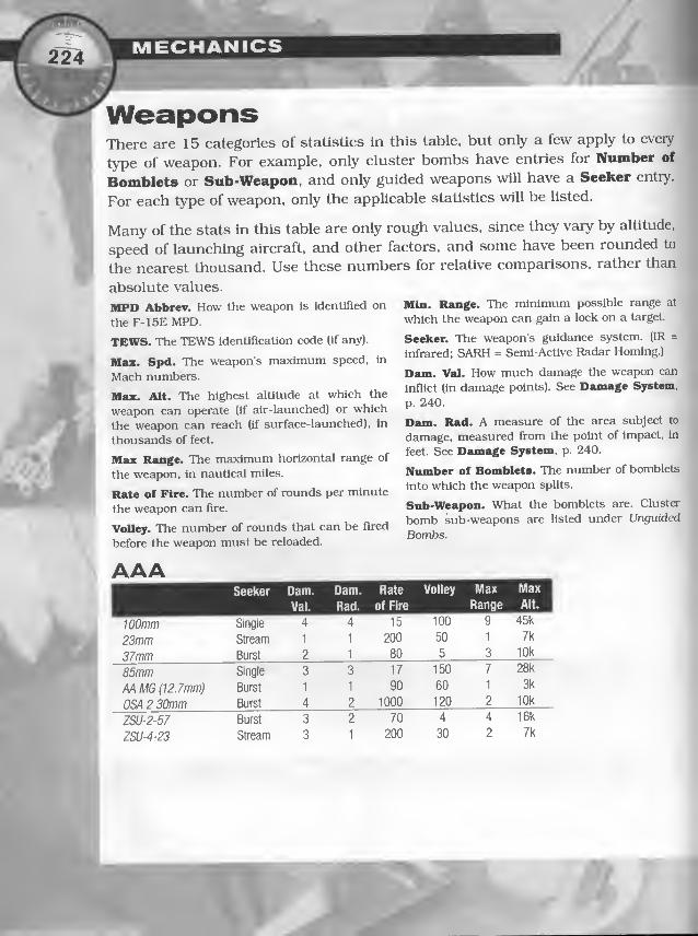
WeaponsThere are 15 categories of statistics in this table, but only a few apply to every
type of weapon. For example, only cluster bombs have entries for Number of
Bomblets or Sub-Weapon, and only guided weapons will have a Seeker entry.
For each type of weapon, only the applicable statistics will be listed.
Many of the stats in this table are only rough values, since they vary by altitude,
speed of launching aircraft, and other factors, and some have been rounded to
the nearest thousand. Use these numbers for relative comparisons, rather than
absolute values.
MPD Abbrev. How the weapon is identified on
the F-15E MPD.
TEWS. The TEWS identificaUon code (if any).
Max. Spd. The weapon's maximum speed, in
Mach numbers.
Max. Alt. The highest alUtude at which the
weapon can operate (if air-launched) or which
the weapon can reach (if surface-launched), in
thousands of feet.
Max Range. The maximum horizontal range of
the weapon, in nautical miles.
Rate of Fire. The number of rounds per minute
the weapon can fire.
Volley. The number of rounds that can be fired
before the weapon must be reloaded.
AAASeeker Dam.
Val.
Dam.
Rad.
Rate
of Fire
Volley Max
Range
Max 1
Alt.1
100mm Single 4 4 15 100 9 45k
23mm Stream 1 1 200 50 1 7k
37mm Burst 2 1 80 5 3 10k
85mm Single 3 3 17 150 7 28k
M MG (12.7mm) Burst 1 1 90 60 1 3k
OSA 2 30mm Burst 4 2 1000 120 2 10k
ZSU-2-57 Burst 3 2 70 4 4 16k
ZSU-4-23 Stream 3 1 200 30 2 7k
Min. Range. The minimum possible range at
which the weapon can gain a lock on a target.
Seeker. The weapon’s guidance system. (IR =
Infrared; SARH = Seml-AcUve Radar Homing.)
Dam. Val. How much damage the weapon can
Inflict (in damage points). See Damage System,
p. 240.
Dam. Rad. A measure of the area subject to
damage, measured from the point of impact, in
feet. See Damage System, p. 240.
Number of Bomblets. The number of bomblets
into which the weapon splits.
Snb-Weapon. What the bomblets are. Cluster
bomb sub-weapons Eire listed under Urtguided
Bombs.

A/A Missiles
Val.
GAME STATS
Dam. Max Min Max Max
Rad. Range Range Spd. Alt.
AN/ALE-40 Dispenser —
A/G MissilesSeeker
AGM-45 Shrike
AGM-65D Maverick
AGM-65G Maverick
Anti-Radar
IR (imaging)
IR (imaging)
AGM-88HARM Anti-Radar
AT-3Anti-Armor Video
SS-IScucTB" —SS-N-2A Styx Radar
Cluster BombsDam.
Val.
Dam. Dam.
Val. Rad.
Max Min Max
Range Range Spd.
lEl
Number of Sub
Bomblets Weapon
CBU-58A BLU-63A
CBU-71A * 200 6b0 BLU-OB
CBU-87 * 150 202 BLU-97
CBU-97 * 150 40 BLU-108
Mk 20 Rockeye II * 125 247 Mk118
* Varies based on release altitude— either widespread, relatively low damage, or concentrated, relatively
high damage. (See Cluster Bomblets. next page.)


r GAME STATS
GunsDam. Dam. Rate Max
Val. Rad. of Fire Rangi 120mm tail cannon 2 3 4000 —23mm cannon 2 2 3000 —23mm tail cannon 2 3 3000 —30mm cannon 3 3 1000 —AC-130H 105 Howitzer 5 5 15 9
AC- 130H 20mm Vulcan 2 3 4000 —AC-130H 40mm Bofors 3 3 300 5
M56A3 20mm ammo 2 3 4000/6000 —PGU-28/B 20mm ammo 3 3 4000/6000 —
SAMsSeeker TEWS Dam. Dam. Volley Max Min Max Max 1
Val. Rad. Range Range Spd. Ait.1
Hawk SARH 30 119 82 3 17 1 2.7 45k
Roland SARH 28 14 10 10 3 — 1.4 18k
SA-2 SARH 2 430 200 1 16 3 3.5 82k
SA-3 SARH 3 132 82 4 10 1 3.5 59k
SA-6 SARH 6 130 33 3 13 2 2.8 46k
SA-7 IR (rear) 7 3 3 1 2 — 1.2 8k
SA-8 SARH 8 44 33 6 5 1 2.4 16k
SA-9 IR (all) 9 6 33 4 4 — 1.8 20k
SA-10 SARH 10 293 148 4 54 3 6 98k
SA-11 SARH 11 154 79 4 18 2 3.5 72k
SA-13 IR (all) 13 7 33 4 3 — 2.3 11k
SA-14 IR (rear) 14 4 3 1 3 — 1.2 16k
SA-15 SARH 15 33 16 8 6 1 2.5 20k
SA-16 IR (all) 16 3 3 1 3 — 1.4 9k
SA-19 SARH 19 20 20 8 4 1 2.6 13k

TEWS Code. If the radar can have a readout on the F-15 TEWS screen, this is
the identifying number that will appear.
Radar lype. STT (Single Target Track), TWS (Track While Scan), L/M/HPRF(Lx)w/Medium/High Pulse Repetition Frequency), CW (Continuous Wave),
O (OptiCcil).
Range. The radar’s range, in nautical miles.
Azimuth and Elevation. The radar’s horizontal and vertical arc, in degrees.
Elevation is a more useful stat than azimuth — knowing a radar’s elevation, you
can know when you have flown close enough that it can no longer track you.
Rate. For SAMs, this is the number of missiles that can be fired in one volley.
Rate does not apply to other radars.
Generation. The radar’s relative “age” as far as its acquisition technology is con-
cerned — a generation 1 radar has the oldest technology, while a generation 3
radar has the most advanced technology.
TEWSCode
Radar
Type
Range
(nm) Azim. Elev. Rate Gen.1
AN/APQ-120 (F-4E) 4 STT.CW 20 60 60 n.a. 2
AN/APQ-144 (F-111) 40 CW 5 60 60 n.a. 2
AN/APQ-153 (F-5E) 5 sn 19 60 60 n.a. 2
APG-65 (F/A-18) 18 Sn.TWS, M/HPRF,CW 76 60 60 n.a. 3
APG-68 (F-16) 16 sn, TWS, lyM/HPRF, CW 80 60 60 n.a. 3
APG-70(F-15) 15 sn, TWS, M/HPRF, CW 73 60 60 n.a. 3
AWACS (AN/APY-1/2) — LPRF 254 360 80 n.a. 3
AWG-9(F-14) 14 sn,Tws, CW 90 60 60 n.a. 3
B-52 (Tail Gun Radar) 43 sn 2 20 20 n.a. 2
Bar Lock (GC!) — LPRF 162 360 85 n.a. 1
Cyrano IV (F-1) 1 sn, MPRF, CW 15 60 60 n.a. 2
Doppler 72 (Tornado) 41 sn, MPRF, CW 29 60 60 n.a. 2
Drum m (OSA II Gun FCR) 55 sn 22 360 85 n.a. 1
Fan Song (SA-2) 2 Sn,TWS, HPRF 40 360 85 3 1
Fire Can (AM) 99 sno 19 360 90 n.a. 1
Fire Dome (SA-11 TELR) 11 sn, MPRF, CW 38 360 80 2 3
Flap Lid (SA-10) 10 Sn,TWS, MPRF 64 360 50 2 3
' /
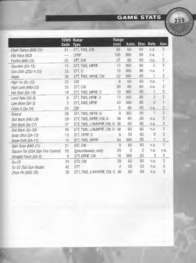
GAME STATS
Land Role (SA-8)
Low Blow (SA-3)
Orion A (Su-24)
Roland
Slot Back (MIG-29)
Slot Back (Su-27)
Slot Back (Su-30)
SnapShot(SA-13)
Snow Drift (SA-11)
Spin Scan (MiG-21)
Square Tie (OSA Styx Fire Control)
Straight Flush (SA-6)
Su-25
Tu-22 (Tail Gun Radar)
Zhuk-PH (MIG-35)
Sn.TWS, HPRF,0
STT.TWS, HPRF
CWSTT, TWS, MPRF, 0
Sn.TWS, MPRF.CW.O
STT.TWS, LVM/HPRF, CW,
STT.TWS, LVM/HPRF.CW,
Sn, HPRF. 0
STT.TWS, MPRF
sn.cw(groundsweep, only)
sn, HPRF, CW
sn.cw
snSn.TWS, L7M/HPRF.CW,
13 360
43 360
9 360
38 60
0 38 60
0 38 60
_54 ^8 60
25 0
16 360
29 60
2 20
0 38 60
60 n.a. 3
85 n.a. 1
60 n.a. 2
85 2"
3
90 n.a. 1
85 1 3
60 n.a. 1
60 n.a. 2
90 1 3
85 2 2
85 2 1
60 n.a. 2
85 1 3
60 n.a. 3
60 n.a. 3
60 n.a. 3
85 2 2
85 1 3
60 n.a. 1
0 n.a. n.£
85 ^ 2
60 n.a. 2
20 n.a. 2
60 n.a. 3
TEWS Radar Range
Code Type (nm) Azim. Elev. Rate Gen.

The aircraft you encounter can each cany a variety of loadouts. Some stores (par-
ticularly guns, dispensers and jammers) are usually consistent across all of an
aircraft’s loadouts. Others (particularly missiles and A/G munitions) vary signif-
icantly among an aircraft’s loadouts.
Each aircraft’s possible loadouts are included in the foUowing list. While you won’t
know for sure which loadout an aircraft is carrying when you encounter it (unless
you examined the aircraft before the mission, using the Mission Builder), this list
does give you the range of possibilities, and that is usually all you need to know.
Note: Most aircrafts also have an Empty loadout, with means the aircraft carries
no weapons.
Since chaff and flares never change for a specific aircraft, those numbers are
listed on the first line of each aircraft. (Of course, you can modify your own air-
craft’s chaff and flare loadout.) All other crucial stores are listed in the appropri-
ate column (Equipment, Gun, A/A and A/G).
For more info on player-aircraft loadouts, see Player Aircraft Stats, p. 209.
F-1 5E Player — chaff (60), and flares (90)
LOADOUT Equipment
Deep Attack AN-AAQ-13 M56A3 AIM-9L (4)
Interdiction AN-AAQ-13 M56A3 AIM-9L (4)
Runway AN-AAQ-13 M56A3 AIM-9L (4)
Smart Bomb AN-AAQ-1 3, -1 4 M56A3 AIM-9L (4)
Standoff AN-AAQ-13, M56A3 AIM-7F(2)
AN/AXQ-14 AIM-9L (4)
Long CAS AN-AAQ-13, -14 PGU-28 AIM-120A(2)
AIM-9M (2)
MiGCAP AN-AAQ-13, -14 PGU-28 AIM-120A(4)
AIM-9M (4)
Runway 2 AN-AAQ-13, -14 PGU-28 AIM-120A(2)
AIM-9M (2)
Smart Bomb 2 AN-AAQ-13, -14 PGU-28 AIM-120A(2)
AIM-9M (2)
Standard AN-AAQ-13, -14 PGU-28 AIM-120A(2)
AIM-9M (2)
Strike AN-AAQ-13, -14 PGU-28 AIM-120A(2)
AIM-9M (2)
' All gun loadouts tor this aircraft feature 512 rounds of 20mm ammunition.
* Numbers in parentheses indicate how many weapons of that type can be carried
Long CAS
MiGCAP
Runway 2
Standard
AN-AAQ-13 M56A3 AIM-9L (4)
AN-AAQ-13
AN-AAQ-13
AN-AAQ-13
AN-AAQ-13, -14
AN-AAQ-13,
AN/AXQ-14
AN-AAQ-13, -14 PGU-28
AN-AAQ-13, -14 PGU-28
AN-AAQ-13, -14 PGU-28
Smart Bomb 2 AN-AAQ-13, -1 4 PGU-28
AN-AAQ-13, -14 PGU-28
AN-AAQ-13, -14 PGU-28
AGM-65D (6)
Mk 20 Rockeyell (12)
Mk 84 (4)
Mk 82 (12) _BLU-107 Durandai (1
2)~
GBU-10G Paveway II (3)
GBU-15(V)-1 (2)
Mk 20 Rockeyell (12)
BLU-107 Durandai (12)
GBU-10G Paveway II (3)
AGM-65D (6)
Mk 20 Rockeye II (12)
Mk 84 AIR (5)
on that station.

LOADOUT Equipment
CAP
Interdiction
4 Mk 84s .
.
AIM-9L 4
Mk82...
Rear Aspect IR
All Aspect IR
SARHActive Radar Missiles
AIM-7F (2)
AIM-9L (2)
AIM-7F (2)
AIM-9L (2)
AIM-9P (4)
AIM-9M (4)
AIM-7M (4)
AIM-120A (4)
Tornado — chaff (60), flares (30)
LOADOUT Equipment
Guns Only
BombLoadoul
Rear Aspect IR
All Aspect IR _
British LGB/AAM _ internal jammer
British BEAD Load internal jammer
Runway Attack internal jammer
30mm(180)
30mm (1 80)
^SOmm (180) AIM-9P (4)
30mm (1 80) AIM-9M (4)
;30mm (1 80) AIM-9L (2)
' 30mm (1 80) AIM-9L (2)
30mm (180) AIM-9L(2)
F-1 5C Eagle — chaff (1 20), flares (60)
LOADOUT Equipment
IAil Aspect iR
SARH
Active Radar Missiles
Full Anti-Air Load M56A3 AIM-7M (4)
AIM-9M (4)
Early DS Eagle Load M56A3 AIM-7F (4)
AIM-9L (4
Early DS Eagle Load
Late DS Eagle Load M56A3 AIM-7M (4)
AIM-9M (4)
* All gun loadouts for this aircraft feature 940 rounds of 20mm ammunition
Su-35 Ranker — chaff (60), flares (30)
ILOADOUT Equipment Gun' A/A
Guns Only
Rear Aspect IR_
All Aspect IR
internal jammer
internal jammer
internal jammer
30mir, !'49)
30mm (149)
30mm (149)
Mk 82 (4)
Mk 82 (4)
Mk 82 (12)
Mk 82 (8)
GBU-1 OE Paveway II (2)
ALARM (3)
BLU-107 Durandal (6)
SARH internal jammer
Full Anti Air Load internal jammer
30mm (149)
30mm (149)
AA-2 Atoll (R- 131) (10)
AA-11 Archer (R-73) (2)
AA-8 Aohid (R-60) (4
1 '
AA-10Alamo(CW)(R-27R)(4)
AA-11 Archer (R-73) (2)
AA-8 Aphid (R-60) (2)

MECHANICS-
r
F-16 Falcon — chaff (60), flares (30)
LOADOUT Equipment Gun ’ A/A A/G
Guns Only M56A3
Rear Aspect IR M56A3 AIM-9P (8)
All Aspect IR M56A3 AIM-9M (8)
Active Radar Missiles M56A3 AIM-120A(8)
Full Anti-Air Load M56A3 AIM-7M (4)
AIM-9M (4)
SARH jammer pod M56A3 AIM-7F (2)
Rockeye Load jammer pod M56A3 Mk 20 Rockeye II (6)
2 Mk 84s/2AIM-9s jammer pod M56A3 AIM-9L (2) Mk84AIR (2)
SEAD jammer pod M56A3 AIM-9L (2)
CBU-58 (6)
' All gun loadouts for this aircraft feature 500 rounds of 20mm ammunition.
AGM-88 HARM (2)
F/A-1 8 Hornet — chaff (30), flares (30)
LOADOUT Equipment Gun
'
A/A A/G
Guns Only internal jammer M56A3Rear Aspect IR internal lammer M56A3 AIM-9P (6)
AllAspect IR Internal jammer M56A3 AIM-9M (6)
SARH internal jammer M56A3 AIM-7M (6)
Active Radar Miss, internal jammer M56A3 AIM-120A(6)
Full Anti-Air Load internal jammer M56A3 AIM-7M (4)
AIM-9M (4)
MkSAandAAM internal jammer M56A3 AIM-7F (2)
AIM-9M (2)
Mk 84 (4)
ModerateAAM internal jammer M56A3 AIM-7F(4).
AIM-9L (2)
SEADLoad internal jammer M56A3 AIM-9L(2) AGM-88 HARM (2)
CBU-58A (2)
’ All gun loadouts for this aircraft feature 570 rounds of 20mm ammunition.
SEPECAT Jaguar — chaff <60), flares (30)
LOADOUT Equipment Gun
'
A/A A/G
Guns Only 30mm 1 15(1)
Rear Aspect IR 30mm (1 50) AIM-9P (6)
All Aspect IR 30mm (150) AIM-9M (6)
French Bomb Strike internal jammer 30mm (150) Matra R 550 Magic (1) Mk82(4)
French 2 CBU's jntemal jammer 30mm (150) CBU-58 (2)
British Bomb/AAM jntemal jammer 30mm (150) AIM-9L (2) Mk 82 (4)
Srffish Rockeye/AAM jntemal jammer 30mm (150) Mk 20 Rockeye II (4)
French A/G Missile jntemal jammer 30mm (150) AGM-65G (1)
AH-64 Apache — chaff (60)
LOADOUT Equipment Gun
'
A/A A/G
Guns Only 30mm (1200)
All Aspect IR 30mm (1200) FIM-92 (4)
AT/FullLoad 30mm (1200) FIM-92(4) AT-3 Anti-Armor Missile (8)

LOADOUT Equipment Gun ’ A/A A^Guns Only M56A3
Rear Aspect IR M56A3 AIM-9P (2)
All Aspect IR M56A3 AIM-9M (2)
SARH M56A3 AIM-7M (6)
Active Radar Miss. M56A3 AIM-54 Phoenix (6)
Full Anti-Air Load M56A3 AIM-54 Phoenix (4)
AIM-7M (2)
AIM-9M (2)
Iranian F-14 AIM-54 Phoenix (2)
AIM-7F (2)
AIM-9L (2)
'All gun loadouts for this aircraft feature 675 rounds of 20mm ammunition.
F-4G Phantom II — chaff (60), flares (30)
LOADOUT Equipment
Rear Aspect IR internal jammer AIM-9P (2)
All Aspect IR internal jammer AIM-9M (2)
SARH internal jammer AIM-7M (2)
Active Radar Miss. internal jammer AIM-120A(2)
Full Anti-Air Load internal jammer AIM-7M (2)
AIM-9M (2)
SEAD Load internal jammer AIM-7F (2) AGM-88 HARM (2)
Heavy SEAD Load internal jammer AIM-7F (2) AGM-88 HARM (4)
Shrike SEAD Load internal jammer AIM-7F (2) AGM-45 Shrike (4)
MiG-21 Fishbed
1 LOADOUT Equipment Gun A/A A/G 1
Guns Only 23mm (200)
RearAspect IR 23mm (200) AA-2Atoll(R-13)(4)
All Aspect IR 23mm (200) AA-8 Aphid (R-60)(4)
SARH 23mm (200) AA-10Alamo(CW)(R-27R)(4)
Full Anti-Air Load 23mm (200) AA-10 Alamo (CW) (R-27R) (2)
AA-8 Aphid (R-60)(2)
Bomb Loaded 23mm (200) FAB-250ShN (4)
Cluster Bomb Loaded 23mm(200) RBK-500 (2)

MECHANICS
MiG-23 Rogger — chaff (60), flares (30)
LOADOUT Equipment Gun
SARH
Full Anti-Air Load
Iraqi Bomb Loaded
Iraqi Cluster Bomb Loaded
23mm (200)
23mm (200)
23mm (200)
23mm (200)
AA-10Alamo(CW)(R-27R)(4)
AA-10Alamo(CW)(R-27R)(2)
AA-8 Aphid (R-60) (4)
AA-2Atoll(R-13)(2) FAB
MiG-25 Foxbat — chaff (60), flares (30)
LOADOUT
Rear Aspect IR
All Aspect IR
SARH
Full Anti-Air Load
Equipment Gun A/A
AA-2 Atoll (R-13)(6)
AA-8 Aphid (R-60) (6)
AA-10Alamo(CW)(R-27R)(4)
AA-10Alamo(CW)(R-27R)(2)
AA-10 Alamo (IR) (R-27T) (2)
AA-8 Aphid (R-60) (2)
FAB-250ShN (6)
RBK-500 (2)
A/G
MiG-29 Fulcrum — chaff (60), flares (30)
LOADOUT Equipment
Guns Only
RearAspect IR
All Aspect IR
SARH~
Full Antl-AIr Load
A/G Missile Loaded
Bomb Loaded
Cluster Bomb Loaded
Gun
30mm (150
30mm (150)
30mm (150)
30mm (150)
30mm (150)
30mm (150)
30mm (150)
30mm (150)
A/A A/G
AA-2Atoll(R-13)(6)
AA-10 Alamo (IR) (R-27T) (2)
AA-8 Aphid (R-60) (4)
AA-10 Alamo (CW) (R-27R) (4)
AA-10Alamo(CW)(R-27R)(2)
AA-8 Aphid (R-60) (4)
AA-8 Ap hid (R-60) (2) AS-13(2)
AA-8 Aphid (R-60) (2) FAB-250ShN (8)
RBK-500 (4)
Mirage FI — chaff (60), flares (30)
A/ALOADOUT Equipment
Guns Only
Rear Aspect IR
All Aspect IR
SARH
Full Anti-Air Load
Coal. Strike/AAM internal jammer
Iraq/Iran Bomb Load
Iraq/Iran CBU Load
Gun30mm (135)
30mm (135)
30mm (135)
30mm (135)
30mm (135)
30mm (1 35)
30mm (135)
30mm (135)
A/G
Matra R 550 Magic (4)
AA-8 Aphid (R-60) (4)
Matra R 530 (4)
Matra R 530 (2)
Matra R 550 Magic (4)
Matra R 530 (2)
Matra R 550 Magic (2)
Matra R 550 Magic (2)
Mk 82 (2)
Mk 82 (4)
RBK-500 (4)

AA-10Alamo(IR)(R-27T)(2)
AA-1 1 Archer (2)
AA-8 Aphid (R-60) (2)
Su-25 Frogfoot — chaff (60), flares (30)
LOADOUT Equipment
Guns Only
Rear Aspect IR
All Aspect IR
Gun A/A A/G
Full Anti-Air Load
30mm (250
30mm (250
30mm (250
30mm (250)
Bomb Loaded
A/G Missile Loaded
Cluster Bomb Loaded
30mm (250i
30mm (250
30mm (250)
AA-8 Aphid (R-60) (8
AA-1 0 Alamo (C
AA-10Alamo(CW)(R-27R)(2)
AA-1 0 Alamo OR) (R-27T) (2)
AA-8 Aphid (R-60) (4)
AA-8Aohid(R-60)(2) Mk82(4
AS-10(4'
AA-8 Aphid (R-60) (2) RBK-500
B-52 Stratofortress — chaff (30), flares (30)
LOADOUT Equipment Gun A/A
Guns Only internal jammer 20mm tail cannon (1242
Full Mk 84s Internal jammer 20mm tall cannon (1 242)
EA-6B Prowler — chaff (30), flares (30)
LOADOUT Equipment
SEAD Loadout
Gun A/A
Mk 84 (20)
A/G
AGM-88 HARM (2)
EF-1 11 A Raven — chaff (30), flares (30)
LOADOUT Equipment Gun A/A

Rear Aspect IR
_AII Aspect IR
Full Anti Air load
Air Shelter Buster internal jammer
Bad Weather internal jammer
AIM-9P (4)
_AIM-9M (2)
AIM-9M(2)‘
AIM-9P (2)
Tank
GBU-15Load
CBULoad
internal Jammer
internal jammer
internal jammer
F-1 17 A Night HawkLOADOUTBunker Buster _
GBU non-pen
Equipment Gun A/A
GBU-24 Paveway III (4) ^
GBU-24 Paveway III (2)
Mk 84 AIR (2)
GBU-12Pavewavl(4)
GBU-15 (V)-31 (2)
CBU-87 (4)
A/G
_GBU-24A Paveway III (2)
GBU-24 Paveway III (2)
Su-22 Fitter — chaff (6G), flares (66)

GAME STATS
chaff (60), flares (30)
LOADOUT Equipment
Guns Only 23mm (400)
AT Gunship 23mm (400) S
All Aspect IR 23mm (400) SA- 1 6 (2)
Iranian F-4E — chaff (60), flares (30)
LOADOUT Equipment
AT-3 Anti-Armor Missile (4
Guns Only
RearAspect IR
All Aspect IR
SARH
Full Anti-Air Load
AJG Missile Loaded
Bomb Load
Cluster Bomb Loaded
AA-2 Atoll (R-13H4)
AA-8 Aphid (R-60) (4)
AIM-7F (4)
AIM-7F (4)
AA-8 Aphid (R-60) (4)
AIM-7F (2)
AA-8 Aphid (R-60) (2)
AIM-7F (2)
AA-8 Aphid (R-60) (2)
M56A3 20mm (640)
AA-2 Atoll (R-13)(2)
AS-10(2)
Mk 82 AIR (4)
AIM-7F (2) RBK-500 (2)
’ All gun loadouts for this aircraft feature 640 rounds of 20mm ammunition.
Mi-24 Hind — chaff (60), flares (30)
LOADOUT Equipment
Guns On!
AT/Gunshlp
All Aspect IR
(12.7mm) (750)
(12.7mm) (750) SA-16(4)
(12.7mm) (750) SA-16(4)
AT-3 Anti-Armor Missile (4
AC-130H Spectre Gunship — chaff (240), flares (1 20)
LOADOUT Equipment
Full Load internal jammer AC-1 30H 105 Howitzer (100)
AC-130H 20mm Vulcan (2 x 3000)
AC-130H 40mm Bofors (256)
MiG-35 Fuicrum —chaff (60), flares (30)
LOADOUT Equipment
Guns Only
Rear Aspect IR
All Aspect IR
internal jammer
internal jammer
internal jammer
SARH internal jammer
Full Anti-Air Load internal jammer
A/G Missile Loaded internal jammer
Bomb Loaded internal jammer
Cluster Bomb internal jammer
30mm ( 1 50 )
30mm (150)
30mm (150)
30mm (150r
30mm (150)
30mm (1 50)
30mm (150)
30mm (150)
AA-2 Atoll (R-131)(6)
AA-10Alamo(IR)(R-27T)(2)
AA-8 Aphid (R-60) (4)
AA-10 Alamo (CW) (R-27R) (2)
AA-10Alamo(CW)(R-27R)(4)
AA-1 1 Archer (R-73) (2)
AA-8 Aphid (R-60) (2)
AA-8 Aphid (R-60) (2) AS-
AA-8 Aphid (R-60) (2) FAB
AS-13(2)
FAB-250ShN (8
RBK-500 (4)

MECHANICS• A. y
' - ’
Other TargetsThis table is straightforward. Loadout and Radar list the weapons and radar the
vehicle mounts. Armor Type affects the effect of various weapons. Armor Points
and Structure Points describe how strong the vehicle is (see p. 240). Some list-
ings here include generalizations, espeeially with regard to buildings. Not every
building in the game fits exactly into one of the categories listed below. In those
cases, use your best judgement for estimating armor and structure, based on the
guidelines listed here.
ShipsLoadout Radar Armor
Type
Armor Struct.
Points Points
Destroyer — — Normal 400 750
Frigate — — Normal 300 500
Oil Tanker — — Normal 75 1000
OSA-2 (SA) OSA 2 30mm twin mu27le Drum Tilt (OSA II Gun) Normal 60 100
OSA-2 (SS) SS-N-2A Styx Square Tie (OSA Styx) Normal 60 100
Perry FFG Hawk Drum Tilt (OSA II Gun) Armored 300 500
Spmance DDG AIM-7M Sparrow Drum Tilt (OSA II Gun) Armored 400 750
TanksLoadout Radar Armor
Type
Armor Struct.
Points Points
BMP-1 AAMG (12.7) — Armored 15 5
BMP-2 AAMG (12.7) — Armored 15 5
M-1 AAMG (12.7) — Armored 60 7
M-3 AAMG (12.7) — Armored 15 5
Boland Roland Roland Armored 15 5
SA-13 SA-13 Snap Shot (SA-13) Armored 15 5
SAM Command Track — — Armored 15 5
T-62 AAMG (12.7) — Armored 30 6
T-72 AAMG (12.7) — Armored 60 7
ZSU-2-57 — — Armored 15 5
ZSU-4-23 ZSU-4-23 Gun Dish (ZSU-4-23) Armored 15 5

APC — — Normal 15
BRDM-1 AAMG (12.7)— Soft 15 5
BRDM-2 AAMG (12.7)— Soft 15 5
BTB-50 AAMG (12.7)— Soft 15 5
BTR-60 AAMG (12.7)— Soft 15 5
Car — — Soft 2 2
Fire Truck — — Soft 3 3
Hummer AAMG (12.7)— Soft 3 3
M-113 AAMG (12.7)— Armored 15 5
MTLB AAMG (12.7)— Soft 15 5
SA-8 SA-8 Land Role (SA-8) Normal 15 5
SA-8 Re-Supply Vehicle — — Normal 15 5
SA-9 SA-9 — Normal 15 5
SCUD TEL SS-1 Scud 'B'— Soft 3 3
Tanker Truck 1-3 — — Soft 3 3
Truck 1, 2. 4 — — Soft 3 3
Truck 3 — — Soft 3 5
Winnebago — — Soft 3 3
Other ObjectsLoadout
Grounded aircraft, large — — Normal
Grounded aircraft, small — — Normal 5 20
Bridge (section) — — Varies 600 600
Building, huge — — Varies 100 2200
Buiiding, iarge — — Varies 75 1250
Building, medium — — Varies 50 600
Buiiding, smail — — Varies 30 125
Bunker, huge — — Hardened 1000 2000
Bunker, large — — Hardened 500 450
Bunker, small — — Hardened 200 100
Camel — — Soft 1 1
Infantry, entrenched — — Varies 10 2
Oil tank, large— — Varies 500 450
Oil tank, small — — Varies 200 100

DAMAGE SYSTEMLike most combat games, the focus of F-15 is destruction. Every weapon cancause a certain amount of damage; every object can absorb a certain amount of
damage before it is destroyed. The key to winning F-15 is understanding the best
ways to get your weapons and your targets close enough together to cause something explosive.
Part of that understanding is knowing how weapons and their targets interact in
F-15, or at least knowing enough to be dangerous. The damage system in F-15 is
complicated, but the basics are fairly straightforward.
Bach weapon has a damage value — how much damage it inflicts at its point
of Impact.
O Damage value is expressed in “damage points” — 2irbitraiy units that don’t
mean anything unless you’re comparing them to another weapon’s damagepoints (to see which weapon inflicts the most damage) or comparing them to
an object’s “structure and armor points” (to see whether the weapon candestroy the object). Structure and armor points are described below.
Bach weapon has a damage radius — over what distance this damage canextend.
O Even when an object is within a weapon’s damage radius, the farther anobject is from a weapon’s point of impact, the less damage it takes from the
weapon. Roughly speaking, doubling an object’s distance from the point of
impact doesn’t just cut the damage in half— it cuts it down to a quarter.
Bach object that can be destroyed has both “armor” and “structure.” Armorprotects structure; when structure is gone, the object is destroyed.
O Armor is expressed in “armor points.”
O Structure is expressed in “structure points.”
O Every time an object is hit, the object’s armor absorbs damage points (unless
the weapon is specifically designed to b)q5ass the armor — it can absorb asmany damage points as it has armor points.
X

DAMAGE SYSTEM /
For example, a BMP-1 has 15 armor points. A weapon with 13 damage points
can’t hurt a BMP-1 — its armor will absorb all of the damage without its
structure taking any damage. A weapon with 19 dEimage points will inflict 4
points of structural damage on a BMP-1 — the BMP-l’s armor absorbs the
first 15 points, but the remaining 4 points will cause structural damage. (Of
course, this assumes that the BMP-1 is at the weapon’s point of impact — if
the weapon doesn’t score a direct hit, the 19 points of damage will be reduced
or even eliminated, depending on how far away the BMP-1 is, and what the
weapon’s damage radius is.)
Armor is not eliminated — each time a weapon strikes an object, that object’s
armor points can absorb the same number of damage points.
Structure can be eliminated — each time a weapon strikes an object, and the
weapon inflicts more damage points than the object has armor points, the
object’s structure points are reduced. When an object’s structure points have
been eliminated, the object is destroyed.
Some weapons are specifically designed to destroy speciHc objects. For
example, the GBU-IOG is designed to penetrate several feet of concrete bunker
before exploding. It tends to inflict much more damage on bunkers and other
hardened objects than do other weapons. Durandal bombs are specifically
designed to crater runways — few other weapons can do significant damage to a
runway.
As an aircraft takes damage, its capabilities are reduced. All aircraft can
take specific damage to its engines, radar, hydraulics, fuel tanks, guns and other
weapons. It isn’t necessary to completely destroy an aircraft to eliminate it. For
example, if an aircraft’s engines are destroyed, it won’t stay in the air much
longer, even if it has taken no other damage.
i

/
F-15E Damage LocationsDamage to a player’s F-15 Is even more specific — 32 locations can be damaged.In essence, each of the 32 locations is a separate “object,” with its own armorand structure points. (In general, each F-15E location has 5 armor points and 5structure points.) However, these locations are interrelated — if one is destroyed,
remaining damage is likely to spill over to nearby locations.
The point at which a weapon strikes a player’s F-15E, determines what might bedamaged. The following diagrams describe what can be hit, based on where a weaponstrikes. Note that many of the diagrams overlap — a weapon that strikes within anoverlapped area can strike a location fi-om any of the combined areas.
For example, a missile that strikes from directly behind the F-15E (l.e., at 180°,
or 6:00) can hit either engine, since the right engine is vulnerable between 90°
and 210° (3:00 to 7:00) and the left engine is vulnerable between 150° and 270°
(5:00 to 9:00). If the missile is also approaching from below at a very sharp angle(steeper than 60°), the emergency hydraulics are vulnerable, as well
20‘— 90° (12:40 to 3:00)
Gun Gun is inoperable.
0 20°— 90° or 270°— 340° (12:40 to 3:00 or 9:00 to 11:20)
Fuel Tanks A fuel tank has been punctured, a fuel pump damaged or a fuel line severed. Your fuel
capacity is significantly reduced.
90°— 270° (3:00— 9:00), pitch greater than 60° (i.e., extreme underbody shot)
Emergency Hydraulics You have no hydraulic control at all.

270°— 90° (9:00 to 3:00)
Radar Radar inoperable.
© 270°— 90° (9:00 to 3:00), level or above
Oxygen Oxygen is low. You will black out if you.do not drop below 1 0,000ft.
HUD You’ve lost your HUD display.
© 270°— 90° (9:00 to 3:00), level or below
Flight Controls The Control Augmentation System (CAS) is inoperable.
PACS You can't release weapons, except by jettisoning them.
Central Computer You’ve lost all displays (HUD, MPDs, UFC, etc.).
Air Data Computer You’ve lost pitch ratio, autopilot attitude hoid and all HUD symbology except heading scale.
Autopilot Autopilot system inoperable.
TEWS TEWS is inoperable (but you can still drop chaff and flares manually).
Target IR Target IR camera is inoperable.
hlAV FUR NAV-FLIR system is inoperable.
150°— 270° (5:00— 9:00)
Left Bleed Air Bleed air leak in the left engine. A fire will start if you don’t shut the engine down.
Left Engine Control Left engine control inoperative. You cannot afterbum, and your maximum engine thrust is
reduced.
Left Oil Pressure Left oil pressure is low. A fire will start if you don’t shut the engine down.
Left Afterburner Left afterburner is inoperative.
Left Fuel Pump Left fuel pump is failing or has failed. If both fail, descend below 30,000ft and do not
afterbum, or you risk flaming out your engines. • f
Left Generator Left generator is failing or has failed. If both generators fail, you’ve lost most displays and .
control of your speed brakes.
Left Main Hydraulic A primary hydraulic circuit is inoperable. When both hydraulic lights are lit, you have no
radar or speed brake control, and reduced flight control. , ,r
Left Engine Left engine is inoperable. ;
90°— 210° (3:00— 7:00)
Right Bleed Air Bleed air leak in the left engine. A fire will start if you don’t shut the engine down.
Right Engine Control Right engine control inoperative. You cannot afterbum, and your maximum engine thrust
is reduced.
Right Oil Pressure Right oil pressure is low. A fire will start if you don’t shut the engine down.
Right Afterburner Right afterburner is inoperative.
Right Fuel Pump Right fuel pump is failing or has failed. If both fail, descend below 30,000ft and do not
afterbum, or you risk flaming out your engines.
Right Generator Right generator failing/failed.lf both generators fail, you’ve lost most displays and control
of your speed brakes.
Right Main Hydraulic A primary hydraulic circuit is inoperable. When both hydraulic lights are lit, you have no
radar or speed brake control, and reduced flight control.
Right Engine Right engine is inoperable.


Note: Specifications and a 1996-97 Jane’s entryfor the F-15E Strike Eagle appear
on pp. 262-295.
Since its maiden flight in 1972, the F-15
Eagle fighter has undergone several evolu-
tions, first as a one-seater, then a two-seater,
then back again. It is the most versatile fight-
er in existence, capable of air-to-air combatat 30,000 feet, nap-of-the-earth approaches
at a mere 100 feet of altitude and blistering
air-to-ground attacks.
t
I
The F-15E Strike Eagle has matured into a precision eiir superiority fighter that
remains unsurpassed in its day emd night attack capabilities. It has ziffection-
ately become known to its crews as the Mud Hen, the Beagle, the Strike Pig, the
Wart Eagle, and sometimes, simply, the E.
FX-15 ProgramBefore the F-15 was developed, the premier U.S. fighter was the McDonnell F-4
Phantom— a multi-role aircraft from the late 1950s that had achieved less-than-
impressive combat kill ratios during the Vietnam War. The Phantom had been
designed for BVR (beyond visual range) combat and not close-range dogfighting.
With the advent of guided weaponry, strategists had assumed that combat wouldrarely, if ever, take place close enough for aircraft to spot one another visually.
However, confrontations and losses in Vietnam challenged this doctrine.
Realizing that long-range capabilities alone did not guarantee fighter success, the
USAF issued a request for proposals for a close-support, dued-role fighter in
1966. None of the resulting designs were considered adequate, however, and the
project stalled.
In 1967, the Soviet Union started production of its Mikoyan MIG-25 Foxbat andunveiled several other advanced aircraft. With the Cold War in full swing, the Air
Force grew worried that its fighters were lagging behind and that the U.S. could
conceivably fall behind technologically. The USAF issued a second request for

proposals, this time specifying a lighter, fixed-wing fighter. After numerous con-
cept plans were submitted by many key players in the industry, McDonnell
Douglas was given the go-ahead to proceed with full-scale designs for the project,
now dubbed Fighter-Experimental 15 (FX-15).
The contract engineers detailed plans for a single-seat, swept-wing fighter with
advanced avionics euid an admirable supply of air-intercept missiles. Air-to-
ground ordnance was also written into the design, although air-to-air combat
was to remain the aircraft’s primary function. The first F-15 prototype flew in
July 1972, and delivery of 107 aircraft was scheduled for November 1974.
Unlike most fighter development programs, the “X” version of the F-15 was never
built — to conserve cost, the aircraft went straight from prototype to production.
Much of the design testing involved half-size, radio-control models that were
dropped from high altitudes. Later, actual prototype evaluations involved ten
separate aircraft, each tasked with a different aspect of aircraft performance.
From A-Model to D-ModelThe first operational versions of the F-15A were delivered, as scheduled, in
November 1974 to the 555th Tactical Fighter Training Squadron of the 58th
Tactical Training Wing at Luke AFB, Arizona. Soon after, a two-seater training
version (the F-15B) was developed. Deliveries to the first combat-ready wing (1st
Tactical Fighter Wing at Langley Air Force Base in Virginia) did not commence
until January 1976. All of these early aircraft had malntencince and engine per-
formance problems, which drove revisions to the original design.
In 1979, the F-15C and D were developed. Like its A-model predecessor, the C-
model was a single-seat aircraft. The D-model was like it in every way, except
that it was a two-seater. Both featured FAST (Fuel and Sensor Tactical) packs
that could house fuel emd support an array of cEimera, sensor and jamming
equipment or weapons on mounting points. Later known as CFTs (Conformed
Fuel Tanks), they extended the range of the aircraft from approximately 2300 to
nearly 3500 nautical miles and expanded its combat capabilities considerably.
Both the F15C and F15D versions also had additional interned fuel teinks eind
improved electronics. An upgraded Hughes AN/APG-63(v)l radar system was
added, and Pratt & Whitney FlOO-PW-220 turbofan engines were incorporated
for the first time.

F-15E STRIKE EAG
Development of F- 1 5EUp to this point, all versions of the F-15 Eagle had been strictly air-to-air fighters.
Despite McDonnell Douglas’ insistence that the F-15 showed extreme air-to-
ground potential, the USAF (and other important parties handing out develop-
ment dollars) still believed that the F- 1 1 1 could accomplish all air-to-ground
missions. But McDonnell Douglas remained convinced that the F-15 could fulfill
its originally conceived purpose as a multi-role fighter. The company privately
teamed with Hughes Aircraft in the late 1970s, and by the time the 1980
Farnsborough air show commenced, an existing F-15B had been converted into
a multi-role fighter.
The two-seater prototype, known as the Strike Eagle, boasted several modifica-
tions that would ensure its later success. First, the back seat was configured
with two monochrome and two color displays for the Weapons System Officer
(WSO — or “wizzo” for short). Secondly, the updated AN/APG-63 radar system
added synthetic aperture radar capabilities (SAR). SAR was especially important
because it allowed the WSO to capture a static, high-resolution image of the tar-
get area and zoom in as necessary to identify targets and terrain features from
far away. Finally, the Strike Eagle was outfitted with a centerline gun pod and
Pave Track laser designator pod. This both alleviated the problem of engaging air-
craft at close range and allowed the fighter to lase its own ground targets instead
of having to rely on a second aircraft or ground unit as a target-spotter.
Despite these added capabilities, the Strike Eagle did not attract any buyers at its
debut air show. The USAF had already started soliciting concept designs for an
Enhanced Tactical Fighter to replace its aging fleet of F-1 1 Is, but it was looking
for a strike fighter that could operate as a lone entity, without the assistance of
escorts or AWACS. The F-15 Strike Eagle prototype had not been developed with
this is mind, and it looked like the development effort might have been in vatn.
In the early 1980s, however, with R&D costs escalating and the worldwide race
for technology heating up, suggestions for an alternative solution surfaced.
Thinking it might be cheaper to convert an existing aircraft than to design an
entirely new one, the USAF scheduled a fly-off between the F-15 and the still-in-
development F-16XL. One of the five test aircraft was the original Strike Eagle
prototype. McDonnell Douglas’ collaborative, independent design effort paid off
In February 1984, when the F-15 was announced the winner of the Dual-Role
Fighter competition. Full-scale development began later that year, and in late
1986, the F-15E Strike Eagle joined the official production list.

Auxiliary ProgramsAn F-15A was modified in the winter months of 1974
and 1975 in an effort to breeik existing speed records.
This specially adapted aircraft had no paint and housed
only the systems it needed to climb and land safely.
These weight-reduction efforts worked, dropping the air-
craft’s weight by an amazing 1800 pounds.
The program was code-named Operation Streak Eagle,
and by 1 February 1975, the aircraft was able to climb
to 30,000 meters in under three-and-a-half minutes.
The trials were held at Grand Forks Air Force Base in
North Dakota, one of the coldest spots available, in
order to maximize the aircraft’s performance. (Colder air
is less dense, and therefore is easier to fly through.) At the time, this shattered
eight existing time-to-climb speed records held by the MiG-25 Foxbat and F-4B
Phantom. These records stood until the development of the Su-27 Interceptor in
the late 1970s.
About this same time, another F- 1 5A was adapted under an anti-satellite (ASAT)
program. The goal of the operation was to develop an aircraft that could climb
high enough to deliver a weapon capable of knocking out an enemy militaiy satel-
lite. The weapon carried by this Eagle was the Vought ASM-135A, a two-stage
rocket with infreired tracking capabilities. Unlike most conventional weapons, the
ASM-135A had no warhead — mere impact would be more than enough to ren-
der a delicate satellite useless.
For the first actual launch, the adapted F-15A climbed to 80,000 feet, where it
released the ASM-135A into empty space. Several other launches were made, with
the weapon directed toward stelleir infrared sources. The only space vehicle to ever
be destroyed by the anti-satellite F-15A was the Solwind P78-1 in September
1985. (The satellite had previously been collecting and reporting spectroscopy
data.) Following these tests, plans were drawn up to modify 20 existing F- 1 5As for
this mission type. However, Congress insisted that testing be terminated in accord
with a U.S.-Soviet treaty to not produce anti-satellite weaponry.
The Eagle had another brush with space-related testing in 1976, when an
existing F-15A was used to measure the durability of thermal tiles for NASA’s
shuttle program. A second F-15A tested an automatically correcting flight con-
trol system under the HIDEC (Highly Integrated Electronic Control) program.

F-15s have been involved in testing
many other new systems, some of
which are currently in place on the
F-15E Strike Eagle. These systems
Include the Global Positioning
Satellite, as well as various jammingand countermeasure packages. AnF-15B was also the test vehicle for
McDonnell Douglas’ Integrated
Flight Fire Control (Firefly III) pro-
gram in 1981, which augmented the
pilot’s controls during different weapon delivery modes. The program never
reached production, since the development of the LANTIRN system fulfllled its
purpose.
Finally, under Operation Agile Eagle, an F-15B was modified in an attempt to
develop an STOL (short takeoff and landing) demonstrator aircraft. The integrat-
ed flight and propulsion control system used for this purpose was designed to
take over several routine piloting duties. Physically, the aircraft body was rein-
forced, and canards (small wing surfaces that can be angled during flight) were
added. The intention was to create an aircraft that could land on short, damagedrunways in severe weather or wind conditions without any assistance from
ground control. The resulting NF-15B flew over 40 test flights in 1988. For the
second phase of testing, small thrust-
vectoring nozzles were added. The pilot
could angle the engine thrust up or
down by 20°, as well as reverse the
direction of thrust. The modifled F-15
could land on less than 2000 feet of
runway, just over one-third the dis-
tance required by a normal F-15. This
test program was completed in August
1991, but no existing F-15s have been
altered as a result.

COMPONENTSEarly Eagles had a reputation of temperamental engine performance, mainly
because the newly developed Pratt & Whitney FlOO-PW-lOO engine had not seen
much operational time emd still had a few unforeseen problems. First, abrupt
changes in throttle settings in the highly maneuverable F-15 caused unexpected
wear on the engines. But more importantly, the engines commonly experienced
stagnation stalls — at high angles of attack and high altitudes, the airflow into
the combustion chamber would be reduced, and power would dwindle or cease.
Solving this problem became paramount.
By 1981, most Dash 100 engines had been replaced with Dash 220s. These
Improved twin turbofan afterburner
engines featured nozzles that could ^be angled to ensure that the air pi
Intakes faced the airflow head-
on at different angles of attack.
fecenUy built F^lSEs have beenPratt S Whlln^ m-tCO-220
fitted with the Dash 229 engine,
which takes advantage of the Digital Engine Control Unit. This modular device
lets the pilot power up from zero to full throttle in just under four seconds. The
Dash 229 requires only half the maintenance of its predecessors and boasts a 6%savings in fuel. To reduce the risk of an engine fire rendering both Dash 229
engines useless, fire suppression bottles are installed between the engine bay
firewalls. In the event of a fire, fire-retardant foam is sprayed through a series of
nozzles, either into the engine itself or inside the compeirtment separating the two
engines.
With its conformal fuel tanks (CFTs), the F-15E requires less internal fuel capaci-
ty than its earlier versions. The aircraft has eight separate internal tanks that can
carry a combined load of nearly 1800 gallons of fuel. If an external CFT is mounted
under each wing base, the aircraft can carry over 1000 extra gallons of fuel and an
array of weapons. (See Weapons, p. 256, for more information about CFTs.)

/
Uv. 'hisjaLJrfc,
> ruTi
Structure
/'/:
/
/•r
When the F-15 fighter series was redesigned to fulfill air-to-ground mission roles,
the airframe itself returned to the drawing board. Since Air-to-ground weaponry
is significantly larger and heavier than air-to-air missiles, the aircraft had to be
redesigned to handle higher G-loads and takeoff weights. Sixty percent of the
original design was changed, and, the rear fuselage and wing bases were
redesigned using lightweight titanium instead of standard alloys. About a quar-
ter of the aircraft is now composed of titanium.
The new airframe on the F-15E Strike Eagle provides other advantages.
Durability has been extended to 16,000 flight hours, nearly a 100% increase.
Extra space has intentionally been built into the structure to allow ground crews
to expand avionics systems in the future. Finally, the maximum weight at which
the aircraft cem take off has increased to 81,000 pounds — more than enough to
accommodate a full weapons and fuel load.
AvionicsNote: Jane’s entries for the F-15E’s avionics systems appear on pp. 272-275.
Although the physical improvements to the F-15E increased its ability to fulfill
its mission role, the heart of the Strike Eagle’s advantage is its high-end avion-
ics systems. The F-15E can fly at night and under adverse weather conditions,
attacking from both high and low approaches. Such versatility — the result of
thousands of man-hours of research and development— gives the F- 1 5E an edge
over its Russian counterparts.
AN/APG-70 RadarThe F-15E’s ability to strike quickly and without warning is primarily due to the
advanced Hughes AN/APG-70 1-band radar system. The radar’s signal processor
can process neairly 30 million operations per second, five times as fast as the old
F- 15-series radar, the AN/APG-63.
The AN/APG-70 emits radar waves which travel outward in a cone away from the
aircraft. If a wave strikes something, it reflects back to the system. By measur-
ing the time it takes for this wave to return, the radar can determine the distance
to the object it struck.

The AN/APG-70 radar is also capable of analyzing the Doppler shift of radar
returns. Doppler shift is the apparent change in the frequency of a wave that
occurs as the relative velocities of the observer and the source change. An exam-
ple of this effect can be observed in sound waves — as the ambulance moves
toward you, the sound of its siren grows higher-pitched. As it passes you and
moves away, the siren grows lower-pitched. Similarly, the AN/APG-70 can mea-
sure the ch2inge in frequency of radar returns to determine Doppler shift effect.
In air-to-air mode, the AN/APG-70 is capable of alternating the pulse repetition
frequencies, or PRFs, of the radar waves it sends out. It can send out high-PRF
waves, which return more accurate information about long-range, high-closure
contacts — objects that return a strong Doppler shift. It can also send out medi-
um-PRF waves, which provide a more accurate picture of low-closure contacts —objects that return only a weak Doppler shift. Better still, the AN/APG-70 can
alternate between high and medium PRFs as it makes its scan, thus collecting
the most accurate information about £dl types of targets.
In 8iir-to-ground mode, the radar can analyze Doppler shift to look for moving
ground targets. Areas where Doppler shift occurs indicate areas where moving
ground targets may be located, and these areas are marked on the radar screen.
Also in air-to-ground mode, the radar can create synthetic aperture radar (SAR)
images of tcirget aireas to the left or right of the aircraft’s nose. These high reso-
lution maps (HRMs or “patch maps”) are static, photo-realistic images that can
be stored and displayed in place of the regular air-to-ground radar display. Fromover 100 miles away, the WSO can use HRMs to help identify tcU-get areas and
ground complexes. At closer ranges, available map resolutions are higher, 8ind
individual targets can be seen.
While the WSO is evaluating these HRMs, the radar is frozen (i.e., not emitting).
Since he can store and retrieve several of these maps, he can make a teirget des-
ignation without having to switch the radar on. In fact, the ability to freeze or
“sniff’ the radar in both air-to-air and air-to-ground modes is one of the distinct
advantages of the AN/AGP-70. Since the aircraft doesn’t continuously broadcast
radar signals, enemy radars find it harder to detect and pinpoint a low-fljdng,
inbound Strike Eagle.

F-15E STRIKE EAGLE--snii.
LANTIRN SystemLANTIRN SystemOne of the easier acronyms to master, the
LANTIRN (Low-Altitude Navigation and
Targeting Infra-Red for Night) system is
the F-15E’s best weapon in somerespects. It allows the aircraft to do
something few other modern fighters
Ccin do — penetrate hostile airspace
under the cover of complete darkness andacquire and designate its own targets. TheLANTIRN system was developed in the late 1980s, just prior to the Gulf War, and
the F- 1 5E was selected as its first operational carrier. However, production was
slow and problematic, so few F-15Es were equipped with the pods until late in
the war.
AAQ-13 AAQ-14
The LANTIRN consists of separate navigational and targeting pods that are mount-
ed under the aircraft. The smallest one, the AAQ-13 navigation pod, contains a
terrain-following radar (TFR) and a forward-looking infrared (FLIR) camera. The
TFR analyzes radar waves reflected from of the ground in front of the aircraft, to
determine the dimensions of the terrain being overflown. This gives the pilot the
ability to fly on autopilot at altitudes as low as 200 feet above ground level. The
FLIR camera superimposes monochrome, infrared video over the HUD, giving the
pilot a clear image of what’s ahead at night or under bad weather conditions.
The other half of the LANTIRN system is the AAQ-14 targeting pod, which con-
tains a second IR camera used for targeting and a laser designator. The AAQ-14targeting IR camera can display infrared video images of air and ground targets.
It can be zoomed in to three different levels. The laser designator that is aligned
in the same direction as the IR camera. The WSO can use the laser to calculate
the range to a target before dropping dumb bombs, or to designate a target for a
laser-guided weapon. Both the FLIR and laser components can swivel in a half-
sphere below the aircraft in order to keep a t£irget in view.

COMPONENTS /
rrapv.Tactical Electronic Warfare System (TEWS)The TEWS is a conglomeration of four separate component systems, which con
trols threat detection and identification and both physicad and electronic countermeasures.
The system uses five mounted antennae to gather and feed information to sever-
al processors. The radar warning receiver (AN/ALR-56C) initiailly detects radar
emissions. Emissions data eire then sorted and identified, and the threats then
displayed on an MPD page available to both pilot and WSO in the cockpit. Theposition of the threat, signal strength and type of radar are all indicated on a top- ,^3down display of the aircraft using coded symbols. VB
v'
By analyzing emissions patterns, the TEWS can also determine whether an
enemy radar is specifically tracking the aircraft. It can also detect when a threat
radar is feeding radar information to a missile it is launching. Based on this data,
the TEWS assigns each threat a priority and alerts the pilot and WSO to whatthreats are doing with visual and audio warnings.
The electronic warfcure warning set (AN/ALQ-128) cues the onboaird jammer(AN/ALQ-135C Internal Countermeasures Set) as to the type, frequency and pat-
tern of threat emissions. The AN/ALQ-135C is then capable of fighting both
pulse £ind continuous-wave sources, as well as adapting to intentional variations
in the enemy’s signal. Thejamming signal can be activated emd deactivated either
manually or automatically.
The AN/ALE-40 dispenses physiccil countermeasures — chaff cmd flares. The
TEWS can be set to automatically control the release of chaff — determining
when to release cartridges, how many to release and how far apart to release
them in order to best combat the specific threat being countered. Flare release
must always be manually controlled, however, as the TEWS cannot detect IR- ,'3.^
,
guided threats. "•'’•'V•'
The TEWS is especially helpful when the target area is dense with threats and Z'
Inbound missiles. The system requires little to no crew intervention, although
either the pilot or WSO can manually control some of the TEWS functions.
r
•f

Note: Specifications and Jane’s descriptionsfor the F-15E Strike Ekigle’s weapons
systems appear on pp. 276-295.
As an adept dual-role fighter, the F-15E is able to carry many different weapon
configurations, depending on the mission objectives. Three separate hardpoint
rails exist — one pylon beneath each wing, and along the centerline of the air-
craft’s belly. All are capable of carrying either bombs or air-to-air missiles, giving
the F-15E an astounding Eirray of armament possibilities.
Conformal Fuel TanksThe addition of the conformal fuel tank (CFT) augments the aircraft’s weapon and
J
fuel loads considerably without sacrificing any normal hardpoints. CFTs can be
mounted just between the wing pylon and wing base on either side of the aircraft.
The tanks blend into the natural shape of the aircraft, visually appearing as an
extension of the aircraft’s body. Three stub pylons protrude from the lower, out-
^ side edge of each CFT and are restricted to carrying a single small bomb each,
usually an Mk 82 or Mk-20 Rockeye. A continuous rack underneath the center
of each tank gives the F-15E the flexibility to cany two large bombs, three small
' bombs or ejector racks for two extra air-to-air missiles. Many times, one CFT will
have a duo ofA1M-7M Sparrows on the continuous rack, while the other CFT car-
ries bombs.
To see which weapon configurations can be loaded on hardpoints and conformal
fuel tanks (CFTs), see the Allowable StationsAVeapons on p. 212.
F-15 with Conformal Fuel Tanks
F-15 without Conformal Fuel Tanks

COMPONENTS
Air-to-Ground WeaponsThe F-15E can cany Mk 20 Rockeyes, Mk 82
(5001b) and Mk 84 (20001b) bombs — all “dumb”
weapons without internal guidance systems.
Their range and accuracy is highly dependent on
release conditions. The faster your airspeed and
the higher your altitude, the further the bombswill travel when released during level flight.
Some unguided weapons fall into the Cluster Bomb Unit (CBU) family. These
weapons explode prior to contact, dispersing smaller bomblets over a widespread
area. Depending on the size and strength of these bomblets’ warhead, these
weapons can be used against hard or soft targets. Some bombs in the CBU fam-
ily have incendiary capabilities.
Guided Bomb Units (GBUs) consist of modified conventional Mk weapons fitted
with some type of guidance system. In the case of the GBU-10, -12, -24 and -28s
Paveways, guidance is by semi-active laser. After release, a laser error detector in
the body of the weapon measures the angle between the bomb’s flight path and
a direct line from the bomb to its target. The latter is computed from the position
of the laser beam played over the target by a laser designator mounted in the
LANTIRN AAQ-14 targeting pod. Canard control fins on the bomb are capable of
make small steering corrections. Laser-guided bombs can be accurately dropped
from high altitudes. During the Gulf War, over three-quarters of these laser-guid-
ed bombs struck their targets as planned.
The GBU-15 is a Mk 84 or BLU-109 bomb fitted with a TV or imaging IR seeker
head. Video imagery can be displayed in a cockpit MPD and used to guide the
weapon before launch. If a datalink pod is mounted on the launching aircraft,
steering signals can also be sent to the weapon after launch.
AGM-65 Maverick is the only air-to-ground missile carried by the Strike Eagle.
Designed for close- to medium-range standoff attacks, heat-seeking AGM-65s are
highly effective on night strikes and against hardened targets. And as fire-and-for-
get missiles, they allow a pilot to break from the attack as soon as they leave the
rail.
Finally, the F-15E has been cleared to cany a total of five B61 nuclear weapons.
It is also a likely candidate for advanced weapons currently in development,
including those guided by inertial navigation and global positioning systems.

F-15E STRIKE EAGLE
Air-to-Air WeaponsIf air-to-air encounters are anticipated,
the F-15E normally carries a loadout
comprising AIM-7 Sparrows, AIM-9
Sidewinders, and/or AIM- 120 AMRAAMs.Up to eight air-to-air missiles can be
loaded, but fewer are often mounted in
order to leave room for more air-to-
ground ordnance.
The AIM-9M Sidewinder is an all-
aspect, infrared missile. This means it
doesn’t have to approach an enemy air-
craft from the rear to be able to home in on it. The Sidewinder is generally con-
sidered a short-range weapon, most effective within three nautical miles. It is
mounted on the standard raiil launcher on the wing pylon.
The AIM-7 is a semi-active radar-homing weapon that requires continuous tar-
get designation from the firing aircraft. It is a medium-range, all-weather, all-
aspect weapon. As of late, it has been replaced by the AIM- 120 AMRAAM. The
active radar-guided AAMRAAM has a greater range and increased reliability.
Unlike the AIM-7, it has an active radar terminal seeker, which can gain its own
lock on a target in mid-course using target position and movement information
supplied by the launching aircraft.
The F-15E is also equipped with a 20mm M61A1 rotary cannon mounted on the
right side of the aircraft, just forward of the wing. Although most combat takes
place beyond gun range, most guided missiles cannot activate their sensor sys-
tems until they’ve travelled several thousand feet. For this reason, guns remain
an integral weapon in air-to-air combat.

The F-15E is by no means an edrcraft to be
taken lightly. It can break the sound barrier
and skim along the earth on autopilot at alti-
tudes as low as 200 feet. With a fully self-suffi-
cient suite of avionics and guided weapons, a
pair of Strike Eagles can act alone, delivering a
precision attack by day or night. Their first
mission is likely to be a deep strike — stealing
far behind enemy lines under the cover of dark-
ness and unloading ordnance on a tactical
ground target. It is this type of mission that gives the Strike Eagle its reputation
as an able ground-pounder.
Today’s F-15E can accomplish nearly any type of ground strike mission. In almost
all cases, the pilot makes a low, nap-of-the-earth (NOE) entry into the area to
avoid radar, climbs just prior to entering the target zone, releases weapons, then
drops back down to NOE for the trip home. By using the LANTIRN navigation and
targeting pods, the Strike Eagle can in most cases follow this lo-hi-lo pattern and
safely reach the target area. If any bogies cross the F-15’s path, the TEWS or
AN/APG-70 In air-to-air mode provides early detection. If the need arises, the
Strike Eagle can climb to meet the attacker and aptly defend itself.
Tlie early F-15s (A, B and C/D variants) were specifically designed as air-to-air
interdiction fighters. Every aspect of these models was oriented toward long-
range air combat against the Russian MiG family and other modern fighters. The
F-15E Strike Eagle, by contrast, currently occupies the dual-role fighter gap
identified by the Air Force in the early 1980s. Its primary duty is to perform air-
to-ground strikes against valuable targets deep inside enemy territory. In an aux-
iliary capacity, the F-15E can hcmdle almost any air foe it encounters. This
makes a flight of Strike Eagles nearly self-sufficient — F-15Es rarely need an
escort to accomplish its mission, and can arrive, strike and exit under the most
adverse fl3ing conditions.

F-15E STRIKE EAGLE
Combat ExperienceIn the Gulf War, F- 1 5Es operated from A1 Khaij airbase in Saudi Arabia, fondly
coined “Al’s Garage” by the air and ground crews that resided there throughout
the war. For five months, pilots and WSOs trained there, preparing themselves
for the strike mission against Iraq that could happen any day. When that day did
come, 17 Januaiy 1991, nineteen Strike Eagles and their crews were ready. The
first hits were delivered by F-15s approaching at altitudes of only 500 feet,
attempting to slide in under enemy radar cover. Their attacks were coordinated
with those of the AH-64D Longbow Apache, which had been tasked with taking
out mamy of Iraq’s communication sites and early wau’ning radEir systems.
Many of the Strike Eagle targets were mobile Scud launchers no larger than fuel
trucks. “Scud-hunting” missions became espeeially important later in the war,
after Iraq began firing these large missiles at Israel. F-15Es hit other targets vital
to Iraq’s military infrastructure as well — communications buildings, strategic
bridges and airfields. Once those were dispensed with, the Strike Eagle becamean anti-tank vehicle, scouring the desert at night for hot objects. Other missions
assigned to Strike Eagles in Iraq were attacks on Najaf, Tallil emd Samawah —all important Iraqi air defense targets — and air support for beleaguered units on
the ground. SEAD (suppression of enemy air defense) missions were critical as
well, paving the way for heavy air strikes. All in all, the F-15E boasted an impres-
sive 95.5% mission capable ratel ratio in the Gulf.
A pair of
Strike Eagies
flying past the
pyramids of Giza.

.r <J _i «
The largest problem faced by Strike Eagles in
the Gulf War was the lack of LANTIRN pods.
Pilots spent many grueling hours in the air, cir-
cling around a refueling tcinker or waiting for
target feeds from E-8A J-STARS. Toward the
end of the conflict, most F-15Es were outfitted
with their own pods and were able to operate
independently. (More about the F-15’s role in
the Gulf War can be found in the game’s Expert
Flight Manual p. A. 1.)
The Persian Gulf was the Strike Eagle’s debut appearance. However, it saw com-
bat again in 1994, when F-15Es were tasked with supporting NATO’s “No Fly
Zones” established over Bosnia. Many of the missions were merely patrols, but
on one occasion, almost 40 Strike Eagles were sent to attack an airfield near
Bihac. Most F-15s in Bosnia during that period flew night-time patrols, canying
air-to-air missiles and laser-guided bombs in case trouble arose. The main pur-
pose for their presence was to maintain no-fly zones through UN-protected areas.
Though most flights were uneventful air patrols or relief efforts, occasional bouts
with enemy aircraft were documented.

The descriptions and specifications in this section were taken from the Aircraft
— Military Aircraft — Fixed Wing section of the 1996-1997 edition of Jane’s
All The World’s Aircraft. Additional specifications for aircraft and ground objects
are available in the gaime. To view them, select reference from the medn menuscreen.
JANE’S SPECIFICATIONS
Descriptions and/or statistics have been abridged due to space constraints.
British spellings have been preserved. If appropriate, the following statistical
information is provided for each entry;
Ailerons. Total surface area of aircraft’s ailerons (In square meters)
Body Diameter. For missiles, the widest point (In millimeters).
Calibre. For artillery and guns, interior diameter of the barrel (In millimeters).
Filling. For bombs, the Inner explosive material.
Fins. Total surface area of aircraft’s fins (in meters squared.)
Flaps. Total surface area of aircraft’s flaps (In meters squared.)
Fuze. For weapons, means by which weapon Is detonated.
Guidance. For weapons, type of system that guides weapon to target after release.
Height overall. For aircraft, distance from ground to highest point on tallplane or fuselage
(In meters).
Launch weight. For weapons, the weight of the weapon Including fuel (in kilograms).
Length. For weapons, measured from tip to base or tall (In meters).
Length overall. For aircraft, measured from nose to tall at longest point on fuselage (in
meters).
Lug Spacing. For weapons, the distance between mounting lugs.
Max combat radius. How far (In nautical miles) the aircraft can operate while fully loaded
and still retain enough fuel to return to base.
Max weapon load. Maximum weight of ordnance (in kilograms) that can be loaded onto
hardpoints If aircraft Is to safely take off or land.
Max fuel weight. For aircraft, weight of fuel (in kilograms) that can be held In different
fuel tank configurations.
Max level speed at height. Maximum speed (in Mach numbers) achieved by the aircraft’s
power plant alone (l.e., not accelerated by diving, etc).

Mu normal operating speed. Normal speed beyond which the aircraft Is not flown (In
knots).
Mu l«iiiHng weight. Weight limit (In kilograms) at which aircraft can make a safe land-
ing — either unrestricted (following normal landing procedures) or at reduced sink
rates (following procedures that extend the landing over a longer-than-normal approach.)
Mu ruge. For aircraft, how feir It can travel (In nautical miles) without refueling.
Mu power loading. Maximum aircraft weight divided by total propulsive power or thrust
at takeoff (expressed In kilograms per kilo Newton).
Mu T-O weights. Limit to which an aircraft can be loaded and still take off (In kilo-
grams).
Mu wing loading. Maximum amount wings can lift, calculated by dividing aircraft
weight by wing area (In kilograms per square meter).
Mu zero-fuel weight. Maximum weight without fuel (l.e.. Including avionics and
weapons. In kilograms).
Muzzle velocity. For weapons. Initial velocity of projectile (In meters/second).
Number of barrels. For weapons, the number of projectile barrels that can fire rounds
simultaneously.
Operating weight empty. Aircraft weight that includes weight of all necessary avionic
equipment (in kilograms), but no ordnance or fuel.
Propulsion. For weapons, method by which the weapon Is propelled.
Rate of fire. For weapons, how many rounds can be fired per minute.
Rudders. Total surface area of aircraft’s rudders (In square meters).
Tailplanes. Total surface area of aircraft's tallplanes (In square meters).
Tailplane spu. Distance from one tip of aircraft’s tailplanes to the opposing tip (In
meters).
Warhead. For weapons, the type of explosive material carried.
Weight. Weight of the weapon (In kilograms).
Wheel track. For aircraft, distance between malnwheels, measured from center of each
wheel (In meters).
Wheel base. For aircraft, distance between the nosewheel and malnwheel, measured from
center of each wheel (In meters).
Wing span. For the aircraft or missile, distance between wingtlps (In meters).
Wings, gross. Measure of wing slenderness as seen In plan view; square of the wingspan
divided by the gross area (as a ratio).'

F-15E STRIKE EAGLE
F- 1 5E Strike Eagley
,
Publication
Section
Country
CompanyTitle
Type
Jane’s All the World’s Aircraft
Aircraft - Fixed-Wing - Militaiy
United States Of AmericaMcDonnell Douglas - McDonnell Aircraft CompanyMcDonnell Douglas F-15E Eagle; McDonnell Douglas F-151
Eagle: McDonnell Douglas F-15S Eagle: McDonnell Douglas
F-15U Eagle: Israel Defense Force name: Ra’am (Thunder)
Two-seat dual role attack/air superiority fighter
ProgrammeDemonstration of industry-funded Strike
Eagle prototype (71-0291) modified from
F-15B, including accurate blind weaponsdelivery, completed at Edwards AFB and
Eglin AFB during 1982; product
improvements for the F-15E were tested
on four Eagles, amongst which were the
Strike Eagle prototype, an F-15C and anF-15D, between November 1982 andApril 1983, including first take-off at
34,019kg, 3,175kg more than F-15Cwith conformal tanks; new weight includ-
ed conformal tanks, three other external tanks and eight Mk 82 bombs; 16 dif-
ferent stores configurations tested, including Mk 84 bombs, and BDU-38 and
CBU-58 weapons delivered visually and by radar.
Full programme go-ahead announced 24 February 1984; first flight of first pro-
duction F-15E (86-0183) 1 1 December 1986: first delivery to Luke AFB, Arizona,
12 April 1988; first delivery 29 December 1988 to 4th Wing at Seymour Johnson
AFB, North Carolina. Small number of F-15Es used for trials with 3246th Test
Wing at Eglin AFB, Florida, and 6510th TW (412th TW from October 1992) at
Edwards AFB, California: trials include 87-0180 with GE FllO-GE-129 engines
in place of FI 00s: $5 million allocated in 1995 to allow USAF to complete test
project. P&W FlOO-PW-229 first flown in F-15E of 6510th TW on 2 May 1990.

F-15E. Basic version, as detailed.
F'lSF. Proposed single-seat version, optimized for air combat: not built.
F-15H. Proposed export version, lacking specialized air-to-ground capability:
supplanted by F-15S.
F-15I. Israeli export version of F-15E: selected November 1993: confirmed 27
January 1994: 21 ordered 12 May 1994 for delivery from 1997 at one per month:
option on four more converted to firm order in November 1995. Tactical elec-
tronic warfare system deleted: to be replaced by Israeli-built integrated system
including active jamming, radar and missile weirning, and dispenser subsystems.
Otherwise identical to USAF F-15E, with FlOO-PW-229 engines, LANTIRN pods,
full capability AN/APG-70 radar, Kaiser holographic HUD, Litton ring laser INS
and VHSIC central computer. Associated equipment includes four Sanders mis-
sion planning subsystems and one Sanders common mapping production system
(CMPS) to assist ground planning, briefing and debriefing activities at total cost
of $6.2 million.
F-15S. Saudi Arabian export version of F-15E, lacking some air-to-air and air-
to-ground capabilities: Saudi Arabian request for 72 aircraft approved by US gov-
ernment in December 1992: Initially designated F-15XP: first funds assigned by
US government on 23 December 1992: contract signature by Saudi government
May 1993: planned delivery rate halved early 1994: now to be one per month
from 1995. First F-15S flown 19 June 1995: official roll-out and handover 12
September 1995. Initial aircraft believed to have been retained in USA for trials:
first two examples delivered to Saudi Arabia in November 1995 were second and
third built.
Saudi versions comprise 24 optimized for air-to-air missions and 48 optimized
for air-to-ground: largely outfitted with F-15C/D systems: AN/APG-70 radar ‘de-
tuned’ to match AN/APG-63 performance, lacking computerized mapping: some
ECM deleted: Lockheed Martin Sharpshooter reduced-capability version of LAN-
TIRN nav/attack pods. Despite earlier planned restrictions, aircraft delivered
with conformal fuel tanks and associated tangential stores attachments.
Armament includes AGM-65D/G Maverick. A1M-9M and AIM-9S Sidewinder mis-
siles, CBU-87 submuniUons dispenser and GBU-10/12 bombs. Saudi pro-
gramme includes about 154 Pratt & Whitney FlOO-PW-229 engines.

F-15U. Version conceived to satisfy United Arab Emirates requirement for 20 to
80 long-range interdictor aircreift, in which it is competing against LockheedMartin F-16, Dassault Rafale, Euroflghter 2000 and Sukhoi Su-37 (Su-30MK).
F-15U Plus proposal anticipates extended range, with additional 2,570kg of fuel
in thicker clipped-delta, 50° leading-edge sweep wing; more stores stations andinternally situated infrared navigation and targeting sensor suite in lieu of LAN-
TIRN. Typical ordnance loads would comprise nine Mk 84 bombs or seven laser-
guided GBU-24S.
Offer envisages co-development, with UAE funding cost of developing and testing
any new components: alternative proposal envisages delivery to UAE of standard
F-15E Strike Eagle under FMS; either option dependent upon US governmentpolicy, which is still to be established.
Costs
$35 million, flyaway; $2,000 million for 21 F-15Is (1993), Israel. $311 million
appropriation for stx F-15Es in FY96.
Design Features
NACA 64A aerofoil section with conical camber on leading-edge; sweepback 38°
42' at quarter-chord; thickness/chord ratio 6.6% at root, 3% at tip; anhedral 1°;
incidence 0°. Twin fins positioned to receive vortex flow off wing and maintain
directional stability at high emgles of attack. Straight two-dimensional external
compression engine air inlet each side of fuselage. Air inlet controllers byHamilton Standard. Air inlet actuators by National Water Lift. Mission includes
approach and attack at night and in all weather; main systems include new high-
resolution, synthetic aperture Hughes AN/APG-70 radar, wide field of view FLIR,
Lockheed Martin LANTIRN navigation (AN/AAQ-13) and targeting (AN/AAQ-14)pods beneath starboard and port air intakes respectively: alr-to-£ilr capacity with
AIM-7 Sparrow, AIM-9 Sidewinder and AIM- 120 AMRAAM retained: rear cockpit
has four multipurpose CRT displays for radar, weapon selection, and monitoring
enemy tracking systems; front cockpit modifications include redesigned up-front
controls, wide field of view HUD, colour CRT multifunction displays for naviga-
tion, weapon delivery, moving map, precision radair mapping and terrain-follow-
ing. Engines have digital electronic control, engine trimming and monitoring: fuel
tanks are foam-filled; more powerful generators: better environmental control.

JANE’S SPECIFICATIONSmi .
.
.
Flying Controls
Plain ailerons and all-moving tailplane with dog-tooth extensions, both powered
by National Water Lift hydraulic actuators: rudders have Ronson Hydraulic Units
actuators: no spoilers or trim tabs: Moog boost and pitch compensator for con-
trol column: plain flaps: upward-opening airbrake panel in upper fuselage
between fins and cockpit. Digital triple-redundant Lear Astronics flight control
system capable of automatic coupled terrain-following.
Structure
Wing based on torque box with Integrally machined skins and ribs of light alloy
and titanium: aluminum honeycomb wingtlps, flaps and ailerons: airbrake panel
of titanium, aluminum honeycomb and graphite/epoxy composites skin. Strike
version of Eagle includes 60% of normal F-15 structure redesigned to allow 9G
and 16,000 hours fatigue life: superplastic forming/diffusion bonding used for
upper rear fuselage, rear fuselage keel, main landing gear doors, and some fuse-
lage fairings, plus engine bay structure. New wing design that would provide 33
percent range increase and give double the number of weapons stations of exist-
ing F-15E revealed in 1994. This could be incorporated in future production air-
craft {including proposed United Arab Emirates F-15U) or installed on existing F-
15s as retrofit programme.
Landing Gear
Hydraulically retractable tricycle
type, with single wheel on each
unit. All units retract forward.
Cleveland nose and main units,
each incorporating an oleo-pneu-
matic shock-absorber. Bendlx
wheels and Michelin AIR X radial
tires on all units. Nosewheel tyre
size 22 X 7.75-9, mainwheel tires
size 36 X 11-18: tyre pressure
21.03 bars (305 Ib/sq in) on all
units. Bendix five-rotor carbon disc
brakes.

Initially, two Pratt & Whitney FlOO-PW-220 turbofans, each rated for take-off at
104.3 kN, installed, with afterburning. USAF aircraft 135 onwards (90-0233),
built from August 1991, have 129.4 kN Pratt & Whitney F100-PW-229s, which
also ordered for Saudi F-15S. Internal fuel in foam-fllled structural wing tanks
and six Goodyear fuselage tanks, total capacity 7,643 litres (2,019 US gallons;
1,681 Imp gallons). Simmonds fuel gauge system. Optional conformal fuel tanks
(CFT) attached to side of engine air intakes, beneath wing, each containing 2,737
litres (723 US gallons; 602 Imp gallons). Provision for up to three additional
2,309 litre (610 US gallon; 508 Imp gallon) external fuel tanks. Maximum total
internal and external fuel capacity 20,044 litres (5,295 US gallons; 4,409 Impgallons).
jjjff Accommodation
£0^. Two crew, pilot and weapon systems officer, in tandem on McDonnell Douglas
ACES II zero/zero ejection seats. Single-piece, upward-hinged, bird-resistant
canopy.
Systems
Lucas Aerospace generating system for electrical power, with Sundstrand
60/75/90 kVA constant-speed drive units. Litton molecular sieve oxygen gener-
ating system (MSOGS) introduced in 1991 to replace liquid oxygen system.
AiResearch air conditioning system. Three independent hydraulic systems (each
207 bars; 3,000 Ib/sq in) powered by Abex engine-driven pumps; modularhydraulic packages by Hydraulic Research and Manufacturing Company.AlliedSignal APU for engine starting, and for provision of limited electrical or
hydraulic power on the ground independently of main engines.
N-

Armament20mm M61A1 six-barrel gun in star- f W'
board wing-root, with 512 rounds (see I^
JM61A1 Vulcan Cannon, p. 276). ^ ^r1 ''LjlflGeneral Electric lead computing gyro. HkProvision on underwing (one per wing) H^ i !
and centerline pylons for air-to-air and ^air-to-ground weapons and external Vfuel tanks. Wing pylons use standard
rail and launchers for AIM-9 v.
Sidewinder and AIM- 120 AMRAAM;
air-to-air missiles; AlM-7 Sparrow and
AIM- 120 AMRAAM can be carried on —ejection launchers on the fuselage or on tangential stores carriers on CFTs.
Maximum aircraft load (with or without CFTs) is four each AIM-7 or AIM-9, or up
to eight AIM- 120. (See AIM-7 Sparrow, p. 278, AIM-9 Sidewinder, p. 280, and
AIM-120 AMRAAM. p. 282.) Single or triple rail launchers for AGM-65 Maverick
air-to-ground missiles can be fitted to wing stations only. (See AGM-65Maverick, p. 284.)
Tangential carriage on CFTs provides for up to six bomb racks on each tank, with
provision for multiple ejector racks on wing and centerline stations. Edo BRU-
46/A and BRU-47/A adapters throughout, plus two LAU-106A/As each side of
lower fuselage. F-15E can carry a wide variety and quantity of guided and
unguided air-to-ground weapons, including Mk 20 Rockeye, Mk 82, Mk 84, BSU-
49, BSU-50, GBU-10, GBU-12, GBU-15, GBU-24, CBU-52, CBU-58, CBU-71,
CBU-87 or CBU-89 bombs; SUU-20 training weapons; A/A-37 U-33 tow target;
and B57 and B61 series nuclear weapons. An AN/AXQ-14 datalink pod is used
in conjunction with the GBU-15; LANTIRN pod illumination is used to designate
targets for laser-guided bombs; AGM-130 powered standoff bomb integrated in
1993. AN/AWG-27 armament control system.
0

Coouns. Magnavox AN/ARC-164 UHF transceiver and UHF auxiliary trcinsceiv-
er with cryptographic capability: Teledyne Electronics AN/APX-101 IFFtransponder: Hazeltine AN/APX-76 IFF interrogator with Litton reply evaluator.
Radar. Hughes Aircraft AN/APG-70 I-band pulse Doppler radar provides air-to-
air capability equal to F-15C, plus high-resolution synthetic aperture mode for
air-to-ground. (See AN/APG'70 Radar for the F'lSE, p. 252.)
Flight. Triple redundant Lear Astronics digital flight control system with auto-
matic terrain-following standard. IBM CP-1075C very high-speed integrated cir-
cuit (VHSIC) central computer introduced in 1992 (replacing CP- 1075).
Honeywell AN/ASK-6 air data computer, Honeywell AN/ASN-108 AHRS,Honeywell CN-1655A/ASN ring laser gyro INS providing basic navigation data
and serving as primary attitude reference system, Collins AN/ARN-118 Tacan,
Collins HSl presenting aircraft navigation information on a symbolic pictorial dis-
play, Collins AN/ARN-112 ILS receiver, Collins ADF receiver. Dome & Margolin
glide slope localiser antenna and Teledyne Avionics angle of attack sensors.
Collins miniature airborne GPS receiver for instaillatlon from 1995.
Instrumentation. FLIR imagery displayed on Kaiser 1R-2394/A wide field of viewHUD: Honeywell vertical situation display set using CRT to present radar, elec-
tro-optical identification and attitude director indicator formats to pilot under all
light conditions: moving map display by Bendlx/King RP-341/A remote mapreader. Honeywell digital map system intended to replace remote map reader
from 1996.
Mission. Lockheed Martin LANTIRN externally mounted sensor package com-prising AN/AAQ-13 navigation pod and AN/AAQ-14 targeting pod. (See LAN-TIRN System, p. 254.)
Self-defense. Northrop Gmmman Enhanced AN/ALQ-135(V) internal counter-
measures set provides automatic jamming of enemy radar signals: Loral
AN/ALR-56C RWR, Magnavox AN/ALQ- 128 EW warning set. Tracer AN/ALE-45chaff dispenser. (See AN/ALQ-135 Jamming System, p. 272.)

Specifications
JANE’S SPECIFICATIONS
r
DIMENSIONS (EXTERNAL)
Wing span 13.05m
Wing aspect ratio 3.0
Length overali _ 19.43m
Height overali 5.63m
Taiipiane span 8.61m
Wheei track 2.75m
Wheel base 5.42m
areas I
Wings, gross 56.49m'
Aiierons (total) 2.46m'
Flaps (total) 3.33m'
Fins (total) 9.78m'
Rudders (total) 1.85m'
Tallplanes (total) 10.34m'
1 WEIGHTS AND LOADINGS (FI OO-PW-220 Engines) |
Operating weight empty" 14,515kg
Max weapon load 11,113kg
Max fuel weight
Internal (JP-4) 5,952kg
CFTs (two) 4,265kg
external tanks (three) 5,396kg
internal and external 15,613kq
Max T-0 weight 36,741kg
Max zero-fuel weight 28,440kg
Max landing weight
unrestricted 20,094kg
at reduced sink rates 36,741kg
Max wing loading 650.5kg/m'
Max power ioading 176kg/kN
performance 1
Max combat radius 685nm
Max range 2,400nm
’ No fuel, ammunition, pylons or external stores

Publication Jane’s Radar And Electronic Warfare SystemsDate 19950613Section Airborne ECM SystemsCountry United States Of AmericaTitle AN/ALQ-135 Jamming SystemType Airborne radar jamming system
Description
The Internal Countermeasures Set (ICS) is a component of the tactical electron-
ic warfare system for the US Air Force F-15 Eagle fighter. It is installed in vary-
ing configurations for the F-15A, F-15C and F-15E. The AN/ALQ-135 operateswith the AN/ALR-56 radar warning system and the AN/ALQ-45 countermea-sures dispenser.
The AN/ALQ-135 is an advanced jamming system emplo}dng high-poweredtransmitters. All equipment is mounted internally and jamming management is
self-contained for the F- 1 5C and F- 1 5E. The system features automatic jammingof threat radars and its dual mode ability allows both pulse and CW threats to
be countered. The computer management system enables the ALQ-135 to adaptautomatically to changes in hostile transmissions.
The basic AN/ALQ-135 consisted of two line-replaceable units (LRUs) plus asso-
ciated waveguides and a four-antenna array. It comprised one Band 1 jammerand two Band 2 jammers. Over the years, the system has continued to evolve
with the capability of the aircraft and changes in the threat.
I

T1.
LANTIRN SystemPublication
Section
Country
Title
Jane's Avionics
Electro-Optics
United States Of AmericaLANTIRN System
Description
The Low Altitude Navigation and Targeting
Infrared for Night (LANTIRN) system consists
of two pods: the AN/AAQ-13 navigation pod
and the AN/AAQ-14 targeting pod. LANTIRN
provides the means by which F-15E and F-
16C/D aircraft can penetrate hostile air-
space at extremely low altitude and high
speed, acquire their targets and deliver guid-
ed and ungulded weapons around the clock.
The LANTIRN system consists of two separate sets of equipment each contained
in its own pod, suitable for underwing or underfuselage attachment. Either or
both pods can be carried, depending on the particular mission requirement.
The AN/AAQ-13 navigation pod contains
a wide field of view FLlR unit and a ter-
rain-following radar. FLIR imagery from
the pod is displayed on a wide field of
view holographic head-up display.
The AN/AAQ-14 targeting pod contains a
stabilization system, wide and narrow
field FLIR, laser designator/ranger, auto-
matic multimode tracker, automatic
infrared Maverick missile hand-off sys-
tem, environmental control unit, pod
control computer, power supply and pro-
vision for an automatic target recognizer.
The targeting pod interfaces with the aircraft controls and displays as well as the
fire control system to permit low-level day and night manual target acquisition
and semi-automatic weapon delivery of guided and unguided weapons.
AN/AAQ-14 Targeting Pod
AN/AAQ-13 Navigation Pod
FLIR window
Air exhaust
Terrain foiiowing
radar radome

F-15E STRIKE EAGLE
AN/APG-70 RadarPublication
Section
Country
Title
Jane’s Avionics
Radcir
United States Of AmericaAN/APG-70 Radar for the F-15E
Description
The radar for the two-seat MeDonnell Douglas F-15E combat aircraft is a sub-
stantially improved version of the APG-63, designated AN/APG-70. It has also
been chosen to upgrade the C/D versions of the F- 15 under the US Air Force's
Multi-Staged Improvement Programme (MSIP). By comparison with the earlier
system, the APG-70 has a far greater RF bandwidth, a larger look-down target
detection range, a one-third increase in MTBF and is packaged in seven units
instead of eight.
The system is compatible with existing and new missiles such as A1M-7F/MSparrow, AIM-9L Sidewinder and AIM- 120 Advanced Medium-Range Air-to-Air
Missile (AMRAAM), and with 20mm cannon.
In the air-to-air role the radar has four search modes: range-while-scan with
high PRF, medium PRF or interleaved PRF, and velocity search. The radar also
has single target track, track-while-scan and raid assessment track modes andvertical search, super search, boresight and auto-guns target acquisition modes.
In the air-to-ground role the radar can produce a high resolution or a real-beamground map; the specification calls for 8.5ft resolution at 20nm range.
1SPECIFICATIONS I
Volume 0.25m'
Weight 251kg
Frequency 8-20 MHz selectable
PRF multiple
Number of LRUs 6


/F-15E STRIKE EAGLE
WeaponsM61A1 Vulcan CannonPublication
Section
Countiy
Title
Type
Jane’s Air-Launched WeaponsGuns, Pods And MountingsUnited States Of AmericaM61A1 Vulcan Cannon20mm Gatling type cannon for aircraft
The M61A1 is a 20mm six-barreled, Gatling type cannon having a rotary action
powered from the aircraft’s hydraulic or electrical supply. A typical installation
with one cannon and 500 rounds of ammunition weighs about 196kg.
When the cannon is fired the rotor revolves anti-clockwise looking in the direc-
tion of fire. Cam followers operate the bolt for each barrel, successively cham-bering, firing and extracting the rounds as the gun rotates.
The Vulcan family of cannons fire standard 20 x 120mm ammunition such as the
M50 series also used for the French M621 and US M36 cannon. These include
the M56 High-Explosive, M56A1 High-Explosive Incendiary, M53A1 Armour-Piercing Incendiary and M55A1 Practice Ball rounds.
1SPECIFICATIONS I
Calibre 20mm
Number of barrels 6
Length 1.83m
Weight 114.5kg
Rate of fire 4,000 or 6,000 rds/min
(selectable)
Muzzle velocity 1 ,030 m/s


Publication
Section
Country
Title
Type
Jane’s Air-Launched WeaponsAir-To-Air Missiles
United States Of AmericaAIM-7 SparrowMedium-range, radar-guided, air-to-air m’issile
The AIM-7 Sparrow 3 missile is an all-weather, all-aspect air-to-air missile whichhas also been adapted for use with shipboard air defense. The missile has four
moving delta-wings at the middle and four fixed delta fins at the rear.
The AIM-7F models were the first Sparrow missiles to use all-solid-state elec-
tronics: this condensed the guidance section, which allowed the warhead to be
moved forward of the wings and allowed the use of a more powerful motor to
Increase both speed and range.
The AIM-7M version has an inverse monopulse semi-active seeker which, with
digital processing, greatly improves the missile’s performance under heavy ECMand weather conditions. This model also has the advantage of an active radar
fuze.
1SPECIFICATIONS AIM-7F AIM-7M
1
Length 3.66m 3.66m
Body diameter 203mm 203mm
Wingspan 1.02m 1.02m
Launch weight 227kg 230kg
Warhead 39kg HE continuous 39kg HE blast/fragmentatlon
Fuze RF Active radar
Guidance Semi-active radar Semi-active radar
Propulsion Solid propellant Solid propellant
Range 40km 45km


\ F-1 5E STRIKE EAGLE
AIM-9 SidewinderPublication
Section
Country
Title
Type
Jane's Air-Launched WeaponsAir-To-Air Missiles
United States Of AmericaAIM-9 Sidewinder
Short-range, IR air-to-air missile
The AIM-9 Sidewinder missile has four swept front control fins and four clipped
delta-wings at the tail with the distinctive rollerons at the trailing-edge tips.
Several modes can be used depending upon the avionics fit in the carrying air-
craft: primarily there is the simple boresight mode, an uncaged scan mode and
a mode with the missile seeker slaved to the aircraft radar or to a helmet-mount-
ed sight.
The AIM-9M version is known as AIM-9S in USAF service. The AIM-9P versions
are 3.07m long, have a body diameter of 127mm, a wingspan of 0.64m and weigh
82kg. These missiles, in the 9P-3 and 9P-4 later models, have an all-aspect
engagement capability; in addition, 9P-4 has an active laser fuze. AIM-9P-5 has
additional IRCCM capability.
AIM-9R was basically the same as AIM-9M but with a visual band CCD seeker
and microcomputer tracker. An improved seeker with dual mode, thought to be
visual and IR, is believed to be in design for later Sidewinder (AIM-9X or
Sidewinder 2000) versions as well as reduced size wings and flns to give a small-
er radar cross-section and less aerodynamic drag.
1SPECIFICATIONS AIM-9L/9M AIM-9P
Length 2.87m 3.07m
Body diameter 127mm 127mm
Wingspan 0.64m 0.64m
Launch weight 87kg 82kg
Warhead 9.5kg HE blast/fragmentation 1 2kg HE blast/fragmentation
Fuze Active laser RF or active laser
Guidance IR IR
Propulsion Solid propellant Solid propellant
Flange 8km 8km


Publication
Section
Countru
Title
Type
Jane’s Air-Launched WeaponsAir-To-Air Missiles
United States Of AmericaAIM- 120 AMRAAMMedium-range, radar-guided, air-to-air missile
AIM- 120 AMRAAM is an all-weather, all-aspect, active radar-guided missile, pow-
ered by a solid propellant motor and armed with a fragmentation warhead. It is
generally similar in configuration to the AIM-7 Sparrow it replaces, but the newweapon is distinguished by its smaller wings, greater range, and improved relia-
bility.
AMRAAM has a modular construction and consists of several major sections: the
guidance unit, the electronics unit, the guidance inertial reference unit, the
armament section, the rocket motor and actuator sections, and the commandlink receiver antennas.
The warhead is filled with 198 separate “candy bar”-shaped projectiles, and it is
reported that the proximity fuzing system can sense which side of the missile a
target is on and direct the blast/projectiles towards the target rather than being
distributed in an even, circular pattern.
Guidance is by an active radar terminal seeker that has the ability to lock on
after launch, using mid-course guidance based on target position and velocity
vectors, both of which are provided by the launch aircraft (both before and after
launch). In consequence there are several guidance modes depending on launch
range and conditions.
1SPECIFICATIONS I
Length 3.65m
Body diameter 178mm
Wingspan 0.63m
Launch weight 157kg
Warhead 22kg HE directed fragmentation
Fuze Active radar
Guidance Command, inertial and active radar
Propuision Solid propellant
Range 50km


/
/
Publication Jane’s Air-Launched WeaponsSection Air-To-Surface Missiles
Country United States Of AmericaTitle AGM-65 Maverick
Type Short- and medium-range, TV-, HR- and laser-guided,
air-to-surface missiles
The AGM-65 Maverick family of air-to-surface missiles has
been steadily developed and improved since the mid-1960s.
Designed for use against tanks and a variety of hard-
ened targets, the later versions have a larger pene-
trating warhead specifically to attack ships,
bunkers and hardened aircraft shelters.
Before launch the pilot climbs to get a
good view of the target, selects a missile \ ^and obtains a picture from the missile /n.
]
tracker on the display. A target is then
selected from the display screen, cross-
hairs are set over the target and the missile launched. The missile homes to the
designated target and the launch aircraft is free to break away immediately after
launch. Guidance for the A and B versions is by TV tracker, and for the D, F and
G versions by an HR seeker. The AGM-65E operates on a quite different principle,
with the missile homing onto coded laser energy reflected from the target.
1SPECIFICATIONS AGM-65D AGM-65F/G |
Length 2.49m 2.49m
Body diameter 305mm 305mm
Wingspan 0.72m 0.72m
Launch weight 220kg 307kg
Warhead 57kg HE shaped charge 136kg blast penetrator
Fuze Impact Impact
Guidance HR
Propuision Solid propellant Solid propellant
Range 3km 25km
J

#4JANE’S SPECIFICATIONS
''’Ml if'
CBU-52, CBU-58 and CBU-71Publication
Section
Country
Title
Type
Jane’s Air Launched WeaponsBombsUnited States Of AmericaSUU-30 Dispensers (With CBU-52/58)Multipurpose cluster bombs
Each CBU comprises a
dispenser (Suspended
Underwing Unit (SUU))
or cluster adapter loaded
with the appropriate BombLive Unit (BLU) or other submunitions. Two of the best known andmost widely used of these dispensers are the SUU-30 and the Mk 7 (Rockeye).
The following list covers the known different types of CBUs using SUU-30s and
believed to be still in service: CBU-52 (254 BLU-61 fragmentation bomblets),
CBU-53 (670 BLU-70 incendlciry bomblets), CBU-54 (670 BLU-68 incendiary
bomblets), CBU-58 (650 BLU-63 fragmentation bomblets), CBU-62 (2025 M38 frag-
mentation grenades), CBU-68 (BLU-48 fragmentation bomblets), CBU-70 (unspeci-
fied submunitions) and the CBU-71 (670 BLU-86A fragmentation bomblets).
The nose fuze used with all variants of the SUU-30 is believed to be the air dri-
ven Mk 339. It provides ground-selected options for varying dispenser opening
times, ensures safe separation from the aircraft prior to arming and initiates the
opening of the body casing allowing bomblets/mines to be released. These are
then dispersed over the target area by aerodynamic forces and descend to the
ground. The size and shape of Impact areas can be changed according to aircraft
speed, altitude, dive angle and the dispenser opening time.
The SUU-30 dispenser is in service with the US forces and is believed to have
been exported, but details are unknown. At least two versions of the SUU-30were used in the 1991 Gulf War against soft targets, the CBU-52 and CBU-58.
1SPECIFICATIONS CBU-52 CBU-58
1
Length 2.33 m 2.33 mBody diameter 430 mm 430 mmTailspan 0.58 m 0.58 m
Lug spacing 356 mm 356 mmWeight 370 kg 430 kg
Filling 254 BLU-61
s
650 BLU-63S
L

'-I'
!l/'r >
F-15E STRIKE EAGLE
CBU-87 (with BLU-97 bomblets)
4cmPublication
Section
Country
Title
Type
Jane's Air-Launched WeaponsBombsUnited States Of AmericaCBU-87/B Combined Effects Munition (CEM) (with BLU-97)
Multipurpose cluster bomb
The CBU-87 is a thin-walled cylindrical bomb-like weapon with a hemispherical
nose, a cruciform tail unit comprising four extending fins and a nose-mounted
fuzing system.
The BLU-97 bomblet is basically a cylindrical canister-type bomb fitted with a
ballute parachute retarding tall unit, and an ejection front-projecting tube used
to sense the optimum standoff distance for activating the shaped charge explo-
sive. Before release the aircrew can select either one of two delivery modes for the
CBU — timed or proximity. In the timed mode the cluster bomb opens at a pre-
set time after weapon release.
1SPECIFICATIONS CBU-87 BLU-97 CEM Bomblet I
Length 2.33m 0.169m stowed
Body diameter 396mm 64mm
Tailspan 0.52m closed, 1 .07m extended n/a
Lug spacing 356mm n/a
Weight 430kg 1.5kg
Fining 202 BLLI-97/B bomblets Zirconium 287 g 70/30 Cyclotol
/
CBU-87

JANE’S SPECIFICATIONS
CBU-97 (with BLU-1 08 bomblets)Publication
Section
Country
Title
Type
Jane’s Air-Launched WeaponsBombsUnited States Of AmericaCBU-97/B Sensor Fuzed Weapon System (SFW) (with BLU-108)Anti-tank cluster bomb
The CBU-97 Sensor Fuzed Weapon system (SFW) was developed by Textron
Defense Systems in order to provide the USAF with a ‘Smeirt’ anti-tank cluster
bomb capable of destroying present and future Main Battle Tanks (MBT) byattacking their top armour.
The SFW is based on the Suspended Underwing Unit (SUU)-65 also known as the
Tactical Munition Dispenser (TMD), which was designed to release a wide variety
of submunltions/bomblets. When used in its CBU-97 configuration, the TMDcarries 10 specially developed submunitions which in turn each carry four Skeet
‘Smart’ anti-armour warheads that use infrared sensors to detect armoured tar-
gets. The submunition is designated BLU-108.
SPECIFICATIONS CBU-97 BLU-108 Bomblet
Length
Body diameter
Tailspan
Lug spacing
Weight
Filling
2.34m
406mm
0.52m closed, 1.07m extended
356mm
450kg
10 BLU-1 08/B bomblets
0.88m stowed
118mm
0.17m
n/a
n/k
4 Skeet warheads

i
Publication Jane’s Air Launched WeaponsSection BombsCountry France
Title DurandalType Penetration bomb
The Durandal bomb was developed in the early to mid-1970s by Matra SA in col-
laboration with SAMP to meet a French Air Force requirement for an anti-run-
way weapon to be used in the disablement of airfields and concrete shelter neu-
tralization by low level attack.
At impact the contact fuze is activated and after a short delay the warhead
explodes. As an option, the explosion may be delayed for several hours by mam-
ual selection prior to take-off. The detonation of the warhead from beneath the
runway surface results in a crater several metres in diameter, 2 to 3m deep, sur-
rounded by a large area where slabs have been raised and cracked.
SPECIFICATIONS
Length 2.49m
Body diameter 223mm
1
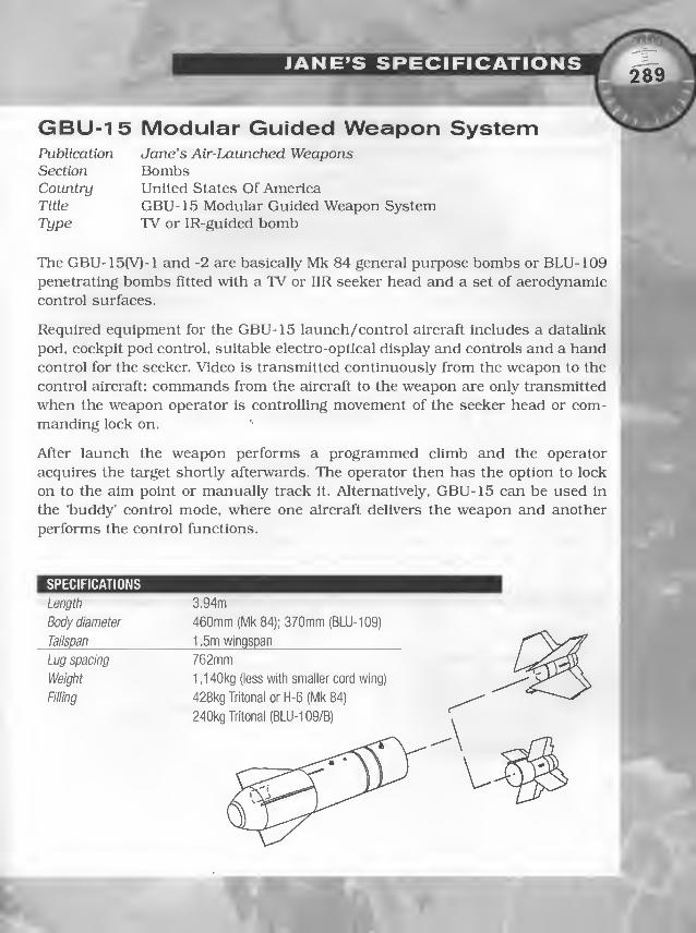
289_
GBU-15 Modular Guided Weapon SystemPublication Jane’s Air-Launched WeaponsSection BombsCountry United States Of AmericaTitle GBU-15 Modular Guided Weapon SystemType TV or IR-guided bomb
The GBU-15(V)-1 and -2 are basically Mk 84 general purpose bombs or BLU-109penetrating bombs fitted with a TV or HR seeker head and a set of aerodynamic
control surfaces.
Required equipment for the GBU-15 launch/control aircraft includes a datalink
pod, cockpit pod control, suitable electro-optical display and controls and a handcontrol for the seeker. Video is transmitted continuously from the weapon to the
control aircraft: commands from the aircraft to the weapon are only transmitted
when the weapon operator is controlling movement of the seeker head or com-
manding lock on.
After launch the weapon performs a programmed climb and the operator
acquires the target shortly afterwards. The operator then has the option to lock
on to the aim point or manually track it. Alternatively, GBU-15 can be used in
the ‘buddy’ control mode, where one aircraft delivers the weapon and another
performs the control functions.
SPECIFICATIONS
Length
Body diameter
Tailspan
Lug spacing
Weight
Filling
3.94m
460mm (Mk 84); 370mm (BLU-109)
1 .5m wingspan
762mm
1 ,140kg (less with smaller cord wing)
428kg Tritonal or H-6 (Mk 84)
240kg Tritonal (BLU-109/B)
k

' 1
Publication
Section
Country
Title
Type
Jane’s Air-Launched WeaponsBombsUnited States Of AmericaPaveway Laser-Guided Bomb Systems
(GBU- 10/ 1 1 / 12/16/17/24)Laser-guided bombs
//
/
1
During the 1991 Gulf War it was revealed that the F-117A Nighthawk stealth i
combat aircraft was involved in laser-guided bomb (LGB) attacks against high'
value strategic targets and bunker command posts. It was also revealed that two,
new t)T)es of penetrating LGBs had been employed which up until then were pro- I
grammes that had been shrouded in secrecy. The first of these was a modified •
Paveway III designated GBU-27, and the other weapon was the GBU-28 that had
been developed for deep bunker penetration and used modified GBU-27 guidance
and control components.
The Paveway III GBU-24 and -24A use the same warheads as the GBU- IOC and
-lOG respectively. Guidance for all Paveway LGBs is by semi-active laser. After
the bomb is released the laser error detector measures the angle between the
bomb’s velocity vector and the line between the bomb and target. Steering cor-
rections are made by moving the nose-mounted canard control fins to adjust the
bomb's trajectory to line up with the target.
4
Vi.k?
1SPECIFICATIONS GBU-10E GBU-10G GBU-12D 1
Length 4.32m 4.26m 3.33m
Body diameter 460mm 370mm 273mm
Tailspan 0.72m closed
1 .68m extended
0.72m closed
1 .68m extended
0.43m closed
1 .34m extended
Lug spacing 762mm 762mm 356 or 762mm
Weight 900kg approx 900kg approx 225kg
Fining 428kg Tritonal 240kg Tritonal 89kg Tritonal
I
.

Body diameter 460mm 370mmTailspan 0.94m closed 0.94m closed
2.0m extended 2.0m extended
Lug spacing 762mm 762mmWeight 900kg approx 900kg approx
Filling 428kg Tritonal 240kg Tritonal

GBU-28 Laser-Guided Penetration BombPublication
Section
Country
Title
Type
Jane’s Air-Launched WeaponsBombsUnited States Of AmericaGBU-27, 28 Penetration Bomb, Laser-Guided Penetration BombsLaser-guided bomb
The GBU-27 and GBU-28 both use the same basic laser guidance system and
control surfaces that are used by the GBU-24 Paveway 111 system, and a folding
stabilizing tail unit developed from the GBU-10 series.
These LGBs are made up of three major components: a common laser guidance
and control section, the main body warhead with suspension lugs, and a com-
mon stabilizing tail unit. Guidance is by semi-active laser, the scanning detector
assembly and laser energy receiver being mounted in the front of the canister
behind the glass dome. After the bomb is released the laser error detector mea-
sures the angle between the bomb’s velocity vector and the line between the
bomb and target. Steering corrections are made by moving the nose-mounted
canard control fins to adjust the bomb’s trajectory to line up with the target.
Depending on the angle of impact, the GBU-27 is reported to be capable of pen-
etrating between 1.8 and 2.4m of reinforced concrete. The GBU-28 is credited
with the ability to penetrate 30m of earth or 6m of concrete.
1SPECIFICATIONS GBU-28
1
Length 5.84m
Body diameter 370mm
Tailspan 0.72m closed
1 .68m extended
Lug spacing n/k
Weight 2,130kg
Filling 306kg Tritonal

Section BombsCountry United States Of America
Title Low Drag General Purpose Bombs Mk 81/82/83/84, BLU-110/111
Type General purpose bombs
Development of this range of low drag general purpose bombs for use by thej
United States armed forces began in the 1950s. The four bombs developed were ''"‘.sn
the Mk 81 (1 13kg). Mk 82 (227kg), Mk 83 (454kg) and Mk 84 (908kg). - r- ‘‘J? 1,
This family of bombs has formed the basis of several other weapon programmes
such as the Laser-Guided Bombs (Paveway) and Electro-Optically Guided Bombs '
(GBU- 15 and AGM-62 Walleye).
The Mk 81, Mk 82. Mk 83 and Mk 84 bombs differ only in size, weight and
destructive capacity. The explosive charge is either Tritonal, Minol, H-6 or
PBXN-109.
1SPECIFICATIONS Mk82 Mk84 1
Length 2.21m 3.84m
Body diameter 273mm 460mm
Tailspan 0.38m 0.64m
Lug spacing 356 or 762mm 762mm
Weight 241kg 894kg
Filling 89kg Tritonal,
Minol, or H-6
428kg Tritonal or H-6

4
Mk 20Publication
Section
Country
Title
Type
Rockeye II
Jane's Air-Launched WeaponsBombsUnited States Of AmericaMK 6. 7 (Rockeye II) Dispenser/ISCB-l/CBU-59Multipurpose cluster bomb
I
Since the Second World War more than 100 types of air-launched dispenser
weapons have been developed and entered service with the US forces. The early
weapons, some of which are still in service, fall into the M and Mk series, while
the newer weapons are generally listed as Cluster Bomb Units (CBUs). Each of
these CBUs comprises a dispenser (Suspended Underwing Unit (SUU)) or cluster
adapter loaded with the appropriate Bomb Live Unit (BLU) or other submuni-
tions. Two of the best known and most widely used of these dispensers still in
service are the Mk 7 (Rockeye II) and the SUU-30.
The Mk 7 dispenser is believed to have been developed in the early 1960s, and in
the mid-60s was adapted to provide US forces with em air-launched cluster bombfor attacking tanks, armoured vehicles and soft targets. The Rockeye II Mk 20
system was designed to cany 247 dual-purpose anti-armour bomblets, and was
fitted with a newly developed nose-mounted fuze system to control the opening
of the Mk 7 dispenser at a predetermined altitude. The bomblet was designated
Mk 118 and the new fuze Mk 339. After extensive testing the Rockeye II system
entered service in the early 1970s.
The Mk 7 dispenser is a bomb-like weapon with a cylindrical body that has an
ogival nose, a cruciform tall unit comprising four fixed extending fins and a nose-
mounted fuzing system.
- When used as the Rockeye II cluster bomb system the Mk 7 dispenser is filled
with 247 Mk 118 bomblets smd weighs 222kg. The Mk 118 bomblets are 316mmlong Including nose probe, have a body diameter of 48mm, a finspan of 45mm
Jand weigh 0.61kg. Their warhead consists of a shaped charge containing 183g of
high explosive. The bomblet is designed primarily as an anti-armour weapon for
use against hard targets such as tanks, armoured carriers and gun emplace-
ments.However, they are equally effective against soft targets such as parked air-
\ craft, truck convoys and small ships. The nose probe contains an Impact fuze
that discriminates between hard and soft targets, foliage and camouflage.
f
\t

JANE’S SPECIFICATIONS
Delivery is similar to that for a 225kg conventional bomb, and once clear of the
aircraft and at the selected time the nose fuze system activates a linear shaped
charge that splits the bombs’ casing open releasing the bomblets or mines. These
are dispersed over the target area by aerodynamic forces and descend to the
ground. The size and shape of impact areas can be changed according to aircraft
speed, altitude, dive angle and the dispenser opening time. In heavily defended
areas the Mk 7 dispenser can be delivered at high speeds and at altitudes as low
as 75m in level flight or 30m with pitch up delivery. A typical Mk 118 bomblet
footprint covers an area of 4800m^ if the Rockeye is released from 150m.
The Rockeye 11 system entered service with the US forces in the early 1970s andis still in operational use with the US and with more than ten other countries
Including Denmark and Sweden.
SPECIFICATIONS Mk 6/7 Dispenser Mk 118 bomblet
Length 2.34m 0.316m
Body diameter 335mm 48mm
Tailspan 0.44m closed
0.86m extended
0.045m
Lug spacing 356mm n/a
Weight 222kg 0.61kg
Filling 247 Mk118 0.183kg shaped charge


>"0
"0
mzD
0m0)

GLOSSARY OF TERMS,
- i1- The Expert Flight Manual contains a glossary of useful terms (pp. B9-C12). This
glossary doesn’t replace that one — however, this list from the USAF Combat
Aircraft Fundamentals 3-3 manual, and includes explanations you might not find
elsewhere. You can use it to make your gaming experience more realistic, espe-
cially when in multiplayer combat.
NOTE: This glossary is a subset of unclassified terms found in MCM 3-1, Vol 1.
MCM 3- 1 should be considered the source in case of conflict.
AA. Aspect angle: the angle between
the defender's flight path and the
attacker’s LOS, measured from the
defender’s 6:00.
Abort. A directive call to cease the
action/event/attack/mission.
ACBT. Air combat training: a general
term which includes (D)BFM, (D)ACM,
and (D)ACT.
>
Acceleration Maneuver. An offensive
or defensive maneuver, flown in the
vertical plane, if possible, to increase or
reduce distance from an objective. Alow yo-yo is an acceleration maneuver.
ACM. Air combat maneuvers: training
designed to achieve proficiency in ele-
ment formation maneuvering and the
coordinated application of BFM to
achieve a simulated kill or effectively
defend against one or more aircraft
from a preplanned starting position.
ACT. Air combat tactics: training
designed to practice element formation
tactics against one or more aircraft
from a BVR set up.
Action. A directive call to Initiate the pre-
briefed attack sequence or maneuver.
Active. A radar missile utilizing
autonomous guidaince.
Adverse Yaw. The tendency ofan aircraft
to yaw away from the applied aileron.
Advisory Control. A radio monitor
mode used when the controlling agency
loses radar, shuts down radcU" to pre-
clude attack, loses radar effectiveness
due to countermeasures, or when the
fighters are beyond radar coverage.
AHC. Advanced handling characteris-
tics: training consisting of maneuvers
throughout the entire flight envelope
designed to familiarize the aircrew with
different flight characteristics as they
apply to aerial combat.
Air Refueling Time. Planned lapsed
time from the ARCT until drop-off.
Alpha Check. Request for/confirmation
of bearing and range to a specific point.

Anchor. Orbit about a specific point;
ground track flown by tanker. During
A/A, informative call indicating a turning
engagement about a specific location.
Angels. Height of the aircraft in thou-
sands of feet.
Angle-Off. A/A: the angle formed by
the extension of the longitudinal axes
of two aircraft as measured from the
defender’s 6:00. Also called track
crossing angle. A/G: the angular differ-
ence between the approach heading
and the attack heading during a pop-
up attack.
AOA. Angle of attack; the angle
between the wing mean chord line and
the relative wind, expressed in degrees
or cockpit units.
AOD. Aim-off distance; a specified dis-
tance to a point long of the target dur-
ing diving deliveries. The velocity vector
is placed at a specific AOD during the
track-to-release portion of the delivery.
Apex. The peak altitude attained dur-
ing a pop-up attack profile.
Apez/Alamo. A training term used to
denote simulated launch of an enemy
all-aspect radar missile.
Aphid/Archer. A training term used to
denote launch of an enemy heat-seek-
Ing missile.
A-Pole. The distance between the
launching aircraft and the target at the
range an active radar missile begins
terminal guidance.
GLOSSARY: A /
Arcing. The use of cutoff to gain clo-
sure — flying a smaller turn circle
inside the defender’s flight path.
ARCP. Air refueling control point: the
planned geographic point where the
tanker and receiver complete the
AR rendezvous.,•%
-
,
ARCT. Air refueling control time; the ^planned time for tanker and receiver
rendezvous over the ARCP.*
ARIP. Air refueling initial point: a geo-|
graphical point upstream from the
ARCP, used to enter the refueling^
track/hold prior to the rendezvous. •
Armament Safety Check. Cockpit
armament switch checks to preclude
inadvertent release/launch of ord-
nance (“Switches Safe").
ASL. Azimuth steering line: HUD sym-
bology providing the pilot steering cues
for A/G weapons employment.
ATF. Actual time of fall: the total time
from ballistic weapons release to impact.
Attack Restriction. Ingress, target ID,
ordnance delivery, or egress restric-
tions dictated by weather, terrain,
friendly forces, political sensitivity, etc.
Authenticate. To request or provide a
response for a coded challenge.
AUTO. Automatic, an A/G weapons
delivery mode.
Autonomous. Aircrew is operating
without the benefit or guidance from a
controlling agency.

APPENDICES
Bandit (Radar/Heat/Striker). Enemyaircraft and ordnance capability.
Base. A reference number used to indi-
cate information such as heading, alti-
tude, fuel state, etc. In the A/G delivery
pattern, a position prior to the final
attack heading.
Beam. A target aircraft with 07-11
left/right AA.
Belly Check. Momentary unloadedbank to check the blind side of a turn-
ing aircraft.
Bent. An informative call indicating
the Identified equipment is inoperative.
BFM. Basic fighter maneuvers: train-
ing designed to apply aircraft hemdling
skills to gain proficiency in recognizing
and solving range, closure, AA, angle-
off, and turning room problems in rela-
tion to another aircraft. The objective of
BFM is either to attain a position fromwhich weapons are employed, deny the
bandit a position from which heemploys weapons, or to defeat weaponsalready employed by a bandit.
Bingo. Fuel state when RTB com-mences.
Blind. An Informative call indicating loss
of visual contact with friendly aircraft.
Blow Through. An informative call
indicating the fighter aircraft continues
straight through at the merge and does
not turn with the target(s).
Bogey. UnldenUfled radar/visual contact.
Bogey Dope. A request for target infor-
mation from GCl/AWACS.
Bone. A term indicating the formation
remains in a racetrack-type holding
pattern (with all wlngman turns into
lead): the desired exit formation is
specified by lead.
Box. Target groups/contacts/forma-
tions in a square/offset square.
Bracket. Fighter element attack geome-
try which places aircraft on opposing
sides of the target either laterally or verti-
cally.
Break (Up/Down/Right/Left). A directive
call, normally to the tanker, to perform
an immediate maximum performance
defensive turn in the direction indicated.
Breakaway. A directive call from
tanker-to-receiver to maneuver so as to
attain immediate horizontal/vertical/
nose-tail separation.
Broadcast Control. A method of con-
trol to pass target Information to sever-
al aircraft by referencing a specific
location (bullseye), series of locations,
or grid system.
Broke Lock. An advisory call indicat-
ing loss of radar/lR lock-on.
Buddy Spike (position/azimuth/alti*
tude). An informative call indicating
reception of friendly A1 RWR.
Bugout (Direction). A directive call to
separate from the engagement in a spe-
cific direction with no Intent to reengage.

( GLOSSARY: B-CI
BuUseye. Code word for a specific ref-
erence point from which the position of
target aircraft are determined.
Bump/Bump-Up. A maneuver to acquire
LOS to the target or laser designation.
Bunt. A crew coordination term indi-
cating a pushover maneuver, as in a
negative-G ridge crossing.
Burner. A directive call to select/dese-
lect afterburner.
Buzzer. An informative CEill indicating
electronic communications jamming.
Canopy Code. A technique to correlate
visual references in the cockpit with
radar teirget azimuth and elevation
enhancing visual lookout and facilitat-
ing an early tally.
CAS. Close air support; an air combat
mission in direct support of ground
troops in contact with enemy forces
(not a normal F-15E mission).
Calibrated airspeed: indicated airspeed
corrected for installation error.
CATA. Collision antenna train angle:
the radar azimuth which places the
target aircraft on a collision course
with the fighter.
CDIP. Continuously displayed impact
point; a visual A/G delivery mode.
Cell. Multiple tankers flying in formation.
CEM. Combined effects munition; a
canistered bomblet anti-armor/per-
sonnel weapon: i.e., CBU-87.
CG. Center of gravity: a point along the
horizontal (fore/aft) axis where the
weight of an aircraft is balanced.
Chaff. Passive ECM deployed by an
aircraft to obscure its radar return or
break the lock of enemy radar systems.
A directive call to dispense chaff. AnInformative call Indicating chaff
returns are detected.
Champagne. An attack of three dis-
tinct groups with two in front and one
behind. The leading two groups
attempt a bracket maneuver while the
third group flies up the middle in a
frontal assault.
Chattermark. A directive call to begin
using briefed radio procedures to
counter communications jamming.
Check ( Right/Left). A directive call
to execute a hard turn the specified
number of degrees and maintain the
new heading.
Chicks. Known friendly fighters.
Christmas Tree. A directive call to
turn on exterior lights momentarily to
facilitate visual acquisition.
Cine Track. A low-G training maneu-
ver employed to practice guns tracking.
Circle (Right/Left). A flight lead direc-
tive call to establish a defensive circu-
lar holding pattern for mutual support.
Clean. No radar contacts in the
assigned area of responsibility.

Cleared. An informative call authoriz-
ing requested action. No engaged/sup-
port roles are assumed.
C1.MAX. Maximum coefficient of lift:
occurs at the AOA where lift is maxi-
mum, creating the maximum turn rate
and G for any flight condition.
Clock Code. A visual position descrip-
tion using the aircraft as a reference.
The nose is 12:00; the tail is 6:00.
Close Control. A mode of control pro-
viding maximum weapons controller
assistance in accomplishing the inter-
cept. Assistance provided varies from
only vectors to complete airspeed,
heading, and altitude direction.
Closing. Range to the bandit/bogey/
target is decreasing.
Closure. Relative velocity of one air-
craft in relation to another.
Cold. Attack geometry resulting in a
roll-out behind the target. A leg of the
CAP point heading away from the
anticipated threats.
Collision Course. A flight path along
which an aircraft is directed, toward a
point where the attacker and the
defensive aircraft theoretically collide.
Combined. Multi-national.
Come Off (Direction). A directive call to
maneuver as indicated to either regain
mutual support or deconflict flight
paths during the engaged/supporting
role swap. Implies both tally and visual.
Comeback. A directive to reverse course.
Comm Jamming. An attempt to inter-
rupt communications.
Commit. Fighter intent to engage/
intercept. Weapons controller contin-
ues to provide information.
Comparison Diagram. A chart com-
paring turn rate, radius, and excess
power for two different aircraft.
Composite Force Training. Scencirios
employing multiple flights of different
types of alrcrcift and missions.
Condition of Vulnerability. A condi-
tion which places the defender in the
lethal envelope of the attacker’s
weapons system. It is possible for com-
batants to arrive at a mutual condition
of vulnerability, normally during a
head-on pass.
Contact. An informative call indicating
a radar/IR target return at the stated
position. Given in bearing, range, alti-
tude (BRA), bullseye, or geographic ref-
erences (geographic) format.
Continue. A directive call for an air-
craft to continue the present maneuverfor attack. Does not imply clearance to
engage or expend ordnance.
Corner Velocity. Minimum airspeed at
which the maximum allowable aircraft
G is generated.
Cover. A directive call to assume the
briefed support position and its associ-
ated responsibilities.

.<9^
GLOSSARY: Cl-Eg
.''V
Crank. A call directing the F-pole
maneuver: implies illuminating the tar-
get at radar gimbal limits.
Cross Turn. A 180° heading reversal
by a flight with the aircraft turning
toward one another.
Cutoff. A request/direction for the inter-
cept of a target using cutoff geometry.
DACT. Dissimilar air combat tactics:
ACT training flown with two different
types of fighter aircraft (e.g., F- 15E ver-
sus F-16C).
DB. Dive bomb: an A/G weapons release
with a dive angle of 30° or greater.
Deadeye. Indication that the airborne
laser designator is inoperative.
Defensive Maneuvering. Maneuvers
designed to negate the attack/ord-
nance of amother aircraft.
Defensive Spiral. A descending, accel-
erating spiral dive using high-G and
continuous roll to negate an attack and
gciin lateral separation.
Deploy. A directive call for the flight to
maneuver to the briefed position.
Designate. Use of aircraft systems to
Identify a ground objective/aircraft as
a target for weapons employment.
DIL. Designated impact line: a HUDsymbology line connecting the velocity
vector cind pipper forA/G CDIP bombing.
DIRECT. A manual A/G bombing
mode used with the SUU-20/BDU-33practice ordnance.
DMPI. Desired mean point of impact: a
specific point of the target area in the
center of a bomb train.
Dogleg. A short leg in an A/G radar
bombing pattern prior to final used for
HRM target mapping.
Downwind. A leg of the A/G radar
bombing pattern opposite the final leg.
DR. Dead reckoning: a navigation tech-
nique using time, heading, cind airspeed.
Drag. An aircraft maneuver to reduce
AA to 60° or less.
Dry. An informative call during A/Gmunitions deliveries indicating no ord-
nance expended/no intent to
release/release not authorized.
DTM. Data trcinsfer module: a small
solid-state memory component used to
transfer mission data from the MSS to
the aircraft avionics system.
Echelon. A call conveying groups/con-
tacts/formation with wlngmen placed
45° behind the leader’s wingline.
ECM. Electronic countermeasures:
actions taken to prevent or reduce the
effective use of sensors/communica-
tions in the electromagnetic spectrum.
Egress. The outbound (exit) portion of
an A/G attack profile.

APPENDICES
Element. A flight of two aircraft.
ESL. Elevation steering line; a HUDsymbol providing pitch/G-loading cues
during the pull-up maneuver for A/Gweapons delivery.
Extend. A directive call to gain energy
and increase separation, with the possi-
ble option of reengaging at a later time.
Filter Turn-On. An AR rendezvous
with the fighter completing the intercept
with a turn to the tanker's heading.
Final. The last leg approaching the tar-
get during an A/G attack profile. Aradio call made when on the final leg.
Flank. A target with a stable AA of 12-
15 L/R. A call directing the flight to
maneuver to present this aspect.
Flare. A p}Totechnic device dispensed
to defeat IR missiles. An informative
call when flares are detected. A direc-
tive call to employ flares.
Flash. Momentary activation of a spe-
cific IFF.
Float. A directive call to expand the
formation laterally within visual limits
to maintain radar contact or prepare
for a defensive response.
FLOT. Forward line of troops; the lead-
ing edge of friendly ground forces,
behind the FEBA.
Flush. Precautionary launch of aircraft
for survival. A 3/9 line overshoot dur-
ing BFM.
Fox. An Informative call for missile
launch; 1 -Radar, 2-IR, or 3-AMRAAM.
F-Pole. A maneuver to maximize the
distance between the launching air-
craft and the target at missile impact.
Frag. Fragmentary ATO, applicable to
one unit or weapons system. Vertical,
lateral, and duration limits of ordi-
nance fragmentation.
Faded. An informative call relating the
previous radar contact is lost.
Faker. A training exercise term denot-
ing aircraft in an adversary role.
Fast. Target speed estimated greater
than 600 knots GS/M 1.0.
FEBA. Forward edge of the battle area;
the boundary between opposing
ground forces.
FENCE Check. Cockpit switch
actions/checks accomplished to prepare
the flight/alrcraft for simulated or actual
combat prior to entering enemy territory.
Engaged. An call conveying maneuver-
ing/request to maneuver with the intent
of achieving a kill. Assumes tally if no
bearing/range information passed.
Engagement. Visual maneuvers byopponent attempting to achieve/defeat
weapons emplo5mient positions.
E-Pole. The minimum range from the
bandit a defender must drag to kine-
matic2illy defeat any missile the bandit
has launched or is launching.

Friendly. An informative call identify-
ing friendly edrcraft.
FSCL. Fire support coordination line;
a boundary established by the ground
forces commander to coordinate
attacks on enemy ground targets, pri-
marily to preclude fratricide.
Furball. A turning fight involving mul-
tiple aircrcift.
Gadget. Fire control radar.
Gimbals (Direction). A call to inform
leader the radar target is approaching
azimuth limits in the direction stated.
Go. A directive to acknowledge a call and
go to the briefed channel/frequency.
Go Active. A directive call to initiate the
briefed HAVE QUICK radio procedures.
Go Secure. A directive call to initiate
the briefed KY-58 radio procedures.
Gorilla. A Icirge force of undetermined
size/formation.
Green. A call indicating the direction
determined to be clearest of
enemy A/A activity. Secure (KY-58)
radio communications.
Group. Radair targets within approxi-
mately 3nm of each other.
GS. Ground speed: TAS corrected
for wind.
Hard (Direction). A directive call to
begin a high-G energy sustaining turn
in the direction indicated.
HAVE 9U1CK. A UHF radio feature
which counters communications jam-
ming through frequency-hopping.
HCA. Heading crossing angle: the angle
between the fighter and target heading.
HD. High drag: (retarded) A/G ordnance.
Head. Target AA of 16-18 (H).
Heads Down. An informative crew
coordination call indicating the aircrew
member is working systems in-cockpit
and is unable to perform clearing/
monitoring duties.
Heater. A slang term for an IR missile.
High. An informative call indicating
target altitude above 30,000ft MSL.
High Aspect BFM. A/A training from a
neutral setup with aircraft approaching
one another head-on. Stresses the use
of lead turns and all-aspect missiles.
Hit. A radar return in the search mode
(A/A). Bomb impact within lethal dis-
tance of a ground target (A/G).
Hook. A directive call to perform a
180° in-place turn.
Hostile. Target aircraft positively iden-
tified as enemy LAW ATO SPINS/ROE.
Guns. A/A or A/S gunshot.

APPENDICES
Hot. A/A: a GCI Informative call the
target is heading toward the fighters.
Intercept geometry which positions the
fighters in front of the target. The leg of
a CAP heading toward the anticipated
threats. A/G: ordnance employment is
authorized, anticipated, or completed.
Hound Dog. An informative call fromthe supporting fighter to the engagedfighter within a visual arena that ashot opportunity exists. This call
Implies a tally and visual exist.
Hung. A/A or A/G weaponlaunch/release commanded, but the
ordnance remained on the aircraft.
Hunter-Killer. A flight of mixed Wild
Weasel and A/G lighters utilized in the
enemy SAM radar destruction role.
Intercept. That phase of A/A mission
between commit and engagement. Theattacker uses his onboard radar, GCI,
and maneuvers to place his aircraft in a
position of advantage to employ ord-
nance, VED, or visually engage the target.
Inteiieaved. Radar search mode alter-
nating medium and high PRF waveforms.
IP. Initial point: a radar/visually sig-
nificant ground reference for final A/Gattack maneuvering.
IPP. Initial pipper placement: a tech-
nique used in manual A/G bombing to
achieve proper delivery parameters byplacing the pipper a specific distance
short of the target while positioned at
the roll-out point.
ID. A directive call to intercept emdidentify the target.
Immelmann. A low-to-high vertical
Intercept.
In. A call during the A/G dive bombingpattern when turning to final, requesting
clearance/announcing intent to drop.
Inadvertent Release. An aircraft sys-
tem malfunction resulting in
launch/release of ordnance.
INFLTREP. Inflight report: a call to the
controlling agency to relay mission suc-
cess, aircraft status, target weather, etc.
Ingress. The inbound (entry) portion of
an A/G attack profile.
Jinking Maneuver. An unpredictable
maneuver to quickly change the air-
craft plane-of-motion to defeat a gunshot or missile already in flight.
JMEM. Joint munitions effectiveness
manual: a reference document used to
determine the best weapons and tactics
to employ against specific target types.
Joint. US/multl-servlce.
Joker. A specific fuel state above Bingo
at which the separatlon/bugout
maneuver is initiated.
Judy. An informative call to the weaponscontroller indicating the aircrew
assumes responsibility for heading, alti-
tude, and airspeed during the intercept.
It requires radar/visual contact.

Kill. A directive call to commit against
an airborne target with clearance to fire.
In a training situation, em informative
call indicating kill criteria are achieved.
LAB. Low angle bomb; an A/G diving
delivery up to 10°. Commonly used for
HD weapons releases.
Ladder. Three or more groups/con-
tacts/formations in trail.
Lag. An attacking aircraft’s pursuit
path to a point behind the target air-
craft (nose pointed behind the target).
LALD. Low angle low drag: an A/G diving
delivery with 10-30° of dive. Commonly
used for slick weapons releases.
LD. Laydown: an A/G level weapons
delivery.
Lead. An attacking aircrcift’s pursuit
path to a point in front of the target
(nose pointed in front of the target).
Lethal Envelope. The envelope within
which the parameters are met for suc-
cessful employment of a munition by a
particular weapons system.
Lift Vector. A vertical plane extending
up through the top of the canopy, per-
pendicular to the aircraft’s wings.
Line Abreast. Two groups/contacts/
formations/aircraft slde-by-slde.
Locked. An informative call made with
a BRA report: this call does not assume
a sort is accomplished.
LOS. Line-of-sight: a straight line
between aircrew member’s eye or sen-
sor directly to an objective.
LOS Rate. A rate of movement across
the canopy/HUD by an alr/ground
objective.
Low. An informative call advising tar-
get altitude is below 10,000ft AGL,
Lufberry. A circular, stagnated “Ivl"
A/A fight with neither aircraft having
an advemtage.
MAD. Minimum approach distance:
the minimum planned range to an A/Gtarget during an LRDT attack escape
maneuver (within maximum ballistic
range of the ordnance, yet outside
threat range).
Maneuverability. The ability of an air-
craft to change direction and magni-
tude of the velocity vector described in
values of turn rate/radius, G-loadlng,
and duration.
MAP. Minimum attack perimeter: the
minimum planned distance from an
A/G target to begin tracking during a
pop-up attack (allows for a given
amount of tracking time and recovery
above the frag envelope).
Marking. Leaving contrails or other-
wise marking the aircraft’s position.
Maverick. Nickname for a terminally-
guided A/G missile (AGM-65) which
utilizes either IR or TV sensors to track
the target.

Maximum Performance. The best pos-
sible G/turn rate performance within
aircraft limits.
Maximum Rate Turn. The turn at
which the maximum number of degrees
per second turn rate is achieved.
Medium. An informative call advising
target altitude is between 10,000ft AGLand 30,000ft MSL.
Merged. An informative call indicating
friendly and target radar returns are
grouped together on the weapons con-
troller’s radar scope. The returns are
too close to break out individually, but
are all within visual range.
Mickey. A Have Quick tlme-of-day signal.
Midnight. An informative call Indicat-
ing GCl/AWACS assistance is nolonger available.
MiG. Common nickname for Soviet
designed fighter aircraft.
Military Crest. A vertical position
along a hill or ridgeline two-thtrds upfrom base-to-summit, used as a terrain
masking reference.
Mixed Force. Employment of a single
flight composed of different types of
aircraft, performing the same tactical
role, under the direction of a single
flight leader.
Mort. Mortality; a state of being dead.
An informative radio call.
MSL. Mean sea level.
MSS. Mission support system; a com-puter system used for route andweapons planning for F-15E missions
as well as loading the DTM.
Mud (Position). An informative inter-
flight call indicating an RWR groundthreat is displayed, normally followed
by clock position.
Music. Electronic radar jamming.
Mutual Support. The combined efforts
of two or more aircraft to provide vlsu-
al/radar lookout to maximize the
group’s firepower and survivability.
Naked. An informative call indicating
no RWR Indications observed — oppo-
site of “Spike."
Negative. A directive call in response
to a request to engage — No.
No Joy. An informative call indicating
the aircrew does not have visual contact
with the bandit, the opposite of “tally.”
Notch. An all-aspect missile defensive
maneuver to place the threat
radar/missile near a beam aspect.
Observation. A formation position onthe tanker’s wing during AR operations.
Oft (Direction). An informative call
the attack is complete and the flight is
repositioning in the stated direction.
Off Station. An informative call indicat-
ing the flight is not in the CAP/hold posi-
tion or the tanker is not in the AR track.

T
Offensive Maneuvering. Maneuvers
against an A/A target to position the air-
craft within valid weapons parameters.
r
GLOSSARY: Ma-Pr
Ph. Probability of hit: a JMEMs esti-
mation of the weapon impacting/fuzing
within the lethal envelope.
Offset. An informative call indicating
to maneuver in the direction called
(with reference to the target;
hlgh/low/left/rlght).
On Station. An informative call indi-
cating the flight is at the CAP/holdposition, ready for mission employ-
ment. The tanker is established in the
refueling track.
Ops Check. A periodic check of fuel
quantity/balance and other aircraft
systems. A directive call to perform the
appropriate checks.
Overshoot. The attacker is flying
through the defender’s 3/9 line from
behind during an A/A engagement. Awingman flying beyond the planned
formation rejoin position.
Package. A geographically separated
collection of groups/contacts.
Padlocked. An informative call indi-
cating the aircrew cannot take their
eyes off the target without a significant
risk of losing tally.
Paint. An informative call indicating
receiving friendly AAl returns.
Pd. Probability of damage; a JMEMsestimation of the level of destruction to a
specific target type using specific muni-
tions/weapons systems/parameters.
Picture. A request to a weapons con-
troller for a situation briefing, includ-
ing real-time information pertinent to
the flight’s specific mission.
PIREP. Pilot report: a radio call to the
controlling agency to relay weather
conditions inflight.
Pitch (Direction). A directive call to
initiate a climbing heading reversal in
the direction stated.
Pk. Probability of kill; a JMEMs esti-
mation of the number/effectiveness of
weapons required to achieve a specific
level of destruction by target type.
Plajrtime. The amount of time an air-
craft is able to remciin on station.
Point Parallel. An AR rendezvous proce-
dure in which the fighter maintains level
flight along a set course and the tanker
turns to roll out in front of the receivers.
Popeye. The aircraft is in IMC.
Post-Hole. An aggressive descending
spiral drag maneuver to break the
enemy’s radar lock.
Pre-Contact. An AR position just
behind the boom. A stabilized position
prior to contact and actual refueling.
Press. A directive call to continue the
attack; mutual support is maintained.
Appropriate engaged/supporting roles
are assumed.

Primary Force. The flight(s) being pro-
tected/escorted.
Ps. Specific excess power; a term used
to compare maneuverability of different
aircraft under similar conditions,
expressed in feet per second.
Pump. A directive call to perform a
pre-briefed sequential maneuver to
stop forward relative motion while
maintaining SA on the threat.
PUP. Pull-up point: a point short of the
target during an A/G pop-up or loft
attack where the maneuver is initiated.
Pure. A pursuit course with the attack-
er continually pointing directly at the
target.
Push. A directive call to switch to newfrequency without acknowledgment.
Quarter-Plane. An aggressive vertical
maneuver perpendicular to the target’s
plane-of-motion employed to prevent a
3/9 line overshoot.
Ra. Maximum aerodynamic missile range.
RAA. Recovery abort altitude.
Ranch House (Altitude). Adirective/information call indicating the
fighters are to return to the CAP point.
RAP. Release aim point: a wind-cor-
rected point on the ground where the
pipper is placed during manual bomb-ing to impact the bomb on target.
RAPE. Release aim point extended:
wind-corrected point on the ground
where the pipper is initially aimed at
rollout, allowing for aircraft drift dur-
ing tracking.
Raygun (Position/Azimuth/Altitude).
Radar lock-on to an unknown aircraft.
Request “Buddy Spike/Naked” reply.
Relative Wind. Airflow across the air-
craft’s wings, exactly opposite the air-
craft flight path.
Rifle. AGM-65 launch informative call.
RmaxI. Maximum launch range for a
radar missile (allows for no maneuver-
ing by the target).
Rmax2. Maximum launch range for a
radar missile (accounts for limited tar-
get maneuvers).
Rmin. Minimum missile launch range
for turn required, fuzing, etc.
Rockeye. Anti-armor cluster bombunit ordnemce; Mk 20.
Rocks. Informative crew coordination
call for terrain avoidance.
ROE. Rules of engagement: specific
restrictions on engagement/destruc-
tion of alr/ground targets, outlined in
the ATO SPINS.
Rolling. An informative crew coordina-
tion call when maneuvering close to
the ground.
Rtr. Range turn-and-run; a maximumlaunch range for a radar missile.

Rumba. Ownshlp maneuvering and
ranging (OMAR).
Run. A directive to perform a defensive
maneuver and place the threat
(radar/missile) on the tail.
SA. Situational awareness: cognizamce
of the total aerial arena picture, such
as: aircraft parameters, target location,
flight position, timing, threats, etc.
SAFE Area. Selected area for evasion:
a designated area in enemy territory to
evade capture and wait for a rescue.
SAM. Surface-to-air missile. An infor-
mative call for visual acquisition of a
SAM launch.
Sandwich. A situation where one air-
craft/element is caught between
enemy aircraft/elements.
Sanitize. A directive call to clear an
assigned area with the radar searching
for additional threats.
Saunter. Fly at best endurance.
Scissors. Defensive maneuvering uti-
lizing a succession of turn reversals
attempting to achieve an offensive pos-
ture following an attacker’s overshoot.
SCL. Set clearance limit: a selected
altitude AGL for TFR flight. Standard
conventional load: a specific
number/type of weapons in various
combinations.
Scramble. Launch the aircraft as soon
as possible.
GLOSSARY: Pr-SI (
SEAD. Suppression of enemy air
defense: a specific mission to conduct
attacks directly on ground-based
threat sites.
Semi-Active. A missile/bomb guld-
emce system where the receiver utilizes
radiation/reflection from the target
(target has been illuminated by anoth-
er source).
Separate. A directive call to extend out
of a specific A/A engagement.
Separation. Vertical/horizontal dis-
tance between cm attacker and defend-
er. Action to increase this distance.
Shackle. A single, simultaneous weave
by two formation members to adjust
formation position.
Shadow. Follow the indicated target.
Shift. A directive to illuminate a sec-
ond target with laser.
Shooter. The aircraft designated to
employ ordnance.
Shotgun. An informative call relating
the launch of an anti-radiation missile
(ARM) by Wild Weasel aircraft.
Sidewinder. AIM-9 IR missile.
Skip It. A directive call to veto a previ-
ous fighter commit/terminate the
intercept/engagement.
Slice. A directive call to initiate a max-
imum performance descending head-
ing reversal in the direction stated.

Slow. An informative call indicating tar-
get airspeed is less than 300 knots GS.
Smash. A combination of kinetic (air-
speed) and potential (altitude) energy.
Snap. A directive call to turn immedi-
ately to the target group described.
Snapshot. A high LOS gunshot.
Sort. An informative interflight call
indicating criteria are met to ensure
flight members have separate radar
contacts.
Sparrow. AlM-7 semi-active radar missile.
Spike. An informative call indicating
enemy A1 RWR is being received.
SPINS. Special instructions: a special
section of the ATO which outlines ROE,airspace restrictions, ID criteria, etc.
Spitter. An aiircraft which has depart-
ed the engagement.
Splash. A/A: target destroyed. A/G:weapons impact.
Split Plane Maneuvering. Aircraft or
elements maneuvering in relation to
one another, but in different planes-of-
motion/altitudes.
Split'S. A pure vertical descending
heading reversal.
Stack. Two or more aircraft/elements
with vertical separation in relation to
each other.
Status. A request call for the individual
aircrew’s tactical situation — normally
offensive, defensive, or neutral. Usually
accompanied with position, altitude,
turn direction, etc. information.
Stinger. A tactical formation with one
aircraft in trail.
Stranger. An unidentified aircraft
which is not a mission participant.
Strangle. A directive call to disable
the IFF.
Strobe. An informative call conve)dng
radar noise Jamming.
Sunrise. An informative call indicating
GCl/AWACS is operational, opposite
of “midnight."
Supporting. The aircraft not currently
engaged, either the leader or wingman.
Switch/Switched. An informative call
the attacker has switched from one tar-
get to another.
Systems. A crew coordination call
indicating an aircrew member is work-
ing tn-cockpit systems, and cannot
perform normal clearing/monitoring
duties.
Tactical Control. A mode of control
similar to close control. The weaponscontroller provides all target informa-
tion, but does not provide fighter head-
ings or altitudes.

GLOSSARYL: Sl-Wa /
Tally. An informative call conveying Uniform. UHF radio identifier.
visual contact with the bandit: the „ . ^ ,. Unintentional Release. Weapon
opposite of No Joy., ,,release/launch through aircrew error.
Target. A/A; a directive call to specify
sorting responsibility. A/G: a ground
objective designated by the system
for attack.
TAS. True airspeed; CAS corrected for
temperature and altitude. Actual air-
craft speed through the air mass.
Threat (Direction). An informative call
from the weapons controller indicating
an untargeted bogey is within lOnm of a
friendly aircraft, in the direction called.
Up. An informative call during an A/Gpop-up attack, made as the pull-up
is initiated.
Vc. Velocity of closure; the combined
velocity of one Eiircraft in relation to
another, usually expressed as positive
Velocity Vector. Actual flight path of
the aircraft, depicted by the HUD veloc-
ity vector symbol.
Tied. An informative interflight call
relating trailing wingmen have radar
contact on the aircraft ahead during a
trail departure/recovery.
Tracking. A stabilized gun solution.
Trail. A tactical formation of aircraft
following the same ground track.
Trailer. The last Eiircraft in a formation.
Trashed. An informative call Indicating
a missile in flight has been defeated.
Tumbleweed. An Informative call con-
veying very limited SA, no joy, blind,
clean, etc. — a request for information.
Vertical Rolling Scissors. A defensive
rolling-descending maneuver applied
to achieve an offensive advEintage.
Very Low. An informative call from a
weapons controller relating the target
is below 300ft AGL.
Vic. Three aircraft/contacts/groups
with the single closest in range (relative
to the opponent) and the element in trail.
Visual. An informative cedi conveying
visual contact with other formation
members/friendly aircraft. The oppo-
site of “blind.”
'I--,
Turn Rate. Turn performance of an
aircraft, commonly expressed in
degrees of heading change per second.
Wall. Three or more aircraft/contacts/
groups in a line abreast formation.
Weapons System. A combination of the
aircraft, avionics, crew, and ordnance.
i

Weave. A continuous crossing of flight
paths by formation members.
Wedge. Tactical formation of two or
more aircraft with the single in front
and the others displaced laterally on
either side, behind the leader’s wingline.
Weeds. An informative call indicating
the aircraft are operating veiy close to
the ground.
Wet. An informative call relating ord-
nance was expended.
What Luck. A request for mission
results.
What State. A request for the aircraft
fuel/armament status, sequentially
stated as: “ _ radar, heat, gun, _ fuel
(pounds).”
Wilco. Will comply.
Wild Weasel. A specialized radar
defense suppression aircraft.
Winchester. An informative call con-
veying no ordnance remaining.
Yo-Yo. A vertical BFM maneuveremployed to Increase or decrease the
attacker’s rate of closure.
ZCL. Zero command line; a line on TFRE-Scope depicting the limit of terrain
returns for correct TFR flight.

IN-FLIGHT CALLS
IN-FLIGHT CALLSThis jargon glossaiy defines phrases that your wlngman and other flights use
during missions. Additional terminology is mentioned in the Expert Fl^ht Manual
(p. B.9) and in the 3-3 Glossary (p. 298).
Ambiguous returns, standby.
JSTARS can’t see a target because it is
out of range or out of radar LOS.
Available for tasking. Your “check-in”
message to JSTARS.
Bearing. Position measured in degrees
(0 is due north, 90 is due east, 180 is
due south, 270 is due west).
Boom Boom! Out go the lights! Your
bomb hit the designated target point.
Ceiling. Upward visibility, either
unlimited (ceiling unlimited) or given
in thousands of feet of altitude
(ceiling angels ...).
Center your steering. You’re off-
course (right or left) during a bombing
run and need to steer toward the ASL.
Check external lights off. WSOrequests that you turn off external lights
prior to crossing into enemy territory.
Check fire! You’ve hit friendly troops,
and the forward air controller orders
you to hold your fire.
Check In/Out. Flight’s radio call to
JSTARS aircraft, letting the JSTARSknow it’s in the area.
Cleared to patrol as fragged. JSTARShas no targets for you at this time, and
you are free to search for targets.
Converting to our six! An enemy air-
craft is tailing you.
Copy. Radio message received.
Do you read me? Request for radio
acknowledgment
.
Drag (Left/Right). Request for flight
aircraft to lead your current A/A target
to the left or right, so you can get a bet-
ter shot angle at him.
B-Mis selected. WSO has engaged
EMIS LMT during refueling to stop
radar emissions.
Enemy chopper. An enemy helicopter
has been spotted.
Enemy striker. An enemy strike air-
craft has been spotted.
Engage/Engaged. Another aircrcift has
assumed an offensive or defensive pos-
ture against am enemy threat (engaged
defensive at this time/engaged defen-
sive SAM/engaged offensive).
Firing cannon — Jink now! WSOrequests that you take immediate, eva-
sive action against enemy gunfire.
Gadget bent. Radar is inoperative.
Going away. Your target is fl5dng away
from you.
r

I
V
t
Going cold. Wingman has turned to
the “cold” side (away from expected
enemies) during a CAP mission.
Going hot. Wingman has turned to the
“hot” side (toward expected enemies)
during a CAP mission.
Going vertical! Your target is going
high relative to your position.
Gomers spotted, engaging. An air-
craft in your flight has sighted an
enemy ground units and initiated an
attack.
Guns! You’re firing your aircraft’s guns.
Heading for the weeds! Your target is
going low relative to your position.
Heads up! A friendly aircraft has
issued a general alert.
Heat. Indicates how many IR missiles
you have remaining (preceded by a
number, i.e., “Two Heat!”).
Helo. Unidentified helicopter spotted.
Hold for traffic/landing traffic.
Request for you to delay takeoff/land-
ing until friendly air traffic clears.
Hydraulics bent. Hydraulic system
has taken damage.
IFF set. Friendly aircraft interrogation
frequency has been set.
Laser off/on. AN/AAQ-14 laser is
Inactive/active.
Launch! Launch! A missile has been
launched at your aircraft.
Losing lase, watch your steering.
You’re off-course during a laser-guided
bombing run and the laser beam is in
danger of being masked by the aircraft.
Maverick! Wingman has fired a
Maverick missile (or, he may call "Rifle”).
MAYDAY! A friendly aircraft is in trou-
ble and in danger of crashing.
Missile Launch/missiles inbound!
WSO has incoming missiles on TEWS.
Movers. JSTARS have spotted moving
ground targets.
Mud Lock on. A ground radar has
locked onto your aircraft.
Music On/Off. Jammers active/inactive.
Offload complete, disconnecting.
Refueling is complete.
On (cleared on). You have permission
to begin a refueling approach.
Orbit Here. You’ve ordered a friendly
aircraft to assume a circular flight pat-
tern at its current location.
Pacs is out! Your ProgrammableArmament Control Set (PACS) is dam-aged: you are unable to fire
missiles/drop bombs.
Pod is masked, lost designation.
You’ve masked the laser beam and lost
the laser designation on the target.
Precontact ready. You’re in precon-
tact position with a refueling tanker
and are ready to connect.

IN-FLIGHT CALLS
Rejoin Flight. You’ve ordered a friend-
ly aircraft to join your formation.
Striker. WSO has spotted an enemystrike aircraft.
Rifle. Wingman has fired a Maverick
missile (or, he may call “Maverick”).
RTB. Request for you to return to
base.
Strobe. An enemy aircraft is emitting
jamming signals.
Tally. Friendly aircraft has made a
visual sighting.
Sandy inbound/SAR packageenroute. A friendly search-and-rescue
team is enroute.
Sanitize Left/Right. You've ordered a
friendly aircraft to fly 90° to left or right
and use radar to find and engage targets.
SAR scramble. Request for a search-
and-rescue team.
Shack. Your bomb successfully hit the
designated target point.
Spike. WSO has spotted radar activity
on the TEWS.
Buddy Spike. A friendly radar has
detected your eiircraft.
Mud Spike. A ground radar has
detected your aircraft.
Spike GCI. A Ground Control
Intercept (ground-based early warning
radar system) has detected your air-
craft.
Spike MiG. An enemy fighter’s radar
has detected your aircraft.
Spike SAM. A SAM radar has detect-
ed your aircraft.
Spike Triple A. An AAA “Triple-A”
site radar has detected your aircraft.
SpUt High/Low. Request for your wing-
man to fly above/below an enemy aircraft.
Tally bandit. Friendly aircraft has
spotted a bandit.
Tally on you. Friendly escort aircraft
has spotted your aircreift.
Tally your bandit. Friendly aircraft
has spotted an aircraft that is engag-
ing you.
Targets in sight, in hot. Friendly air-
craft has spotted its assigned ground
targets and is commencing an attack.
Touching down at LZ now. Friendly
helicopter has touched down at specif-
ic landing zone.
Transmitting new coordinates on
dolly. Updated wa)qDoints 8ire being
sent to your curcraft’s computer via
secure data link.
Vector/vectoring. New navigational
coordinates are being sent to your air-
craft or other friendly aircraft.
Weeds. Enemy Eurcraft at low cilti-
tudes.
Wilco. Friendly aircraft will comply
with your request.
Winchester. You are out of missiles/
bombs.
Zero gun. You are out of gun ammo.

TheiWorld^Leader, in
TOMB m fi-
gAlD|D flolWBOftlctai GameSecrets
Game Secrets
PUZZLES
SECBETS.
ptVEAL'
Jh€ Champion's
Strategy Gukic
*.nattvu
Prima Publishing
Tomb Raider"* II
The Official Strategy Guide
$12.99
Dungeon Keeper'Official Secrets
$19.99
OddlAforld"*:Abe's Oddysee
The Official Strategy Guide
Tomb Raider'Game Secrets
$12.99
Shadows ofthe Empire"*
Game Secrets
$12.99
Dark Earth"*The Official Strategy Guide
$19.99
Nascar Racing" II
The Champion's Handbook
$19.99
The Official Strategy Guide
$19.95
PO Box 629000 • El Dorado Hills, CA 95762To Order Call 1 •800*531 *2343
Secrets of the Games® is a registered trademark ofPrima Publishing, a division of Prima Communications, Inc.

Publishing
Diablo"*The Official Strategy Guide
$19.99
MDK-The Official Strategy Guide
$12.99
lAfarlords"' III:
Reign of Heroes
The Official Strategy Guide
$19.99
Sid Meier'sCivilization II"
The Official Strategy Guide
$19.99
ude your VISA or Mastercard number, expiration date, and your name and address. Please add $4.00 shipping and handling for the first book. ($1 .00 for each additional
k) in the U.S. (California residents add 7.25% sales tax. Tennessee residents add 8.25% sales tax. Maryland residents add 5% sales tax. Indiana residents add 5% sales
I. Allow 2-3 weeks for delivery. Canadian orders please add $0.00 shipping and handling ($I .00 for each additional book) and 7% GST. U.S. funds only, please,
na s Secrets of the Games® series is distributed in the UK and EEC by Bqxiree Lid. Look for Prima books at your local bookshop, or order directly through
lehampton Book Services; Tel. 44 (0) 1903 732596 Fax 44 (0) 1903 730914 Access. Visa and Mastercard accepted.
^ OfFiciac
Imperialism"’The Official Strategy Guide
$19.99
X-COMApocalypse”The Official Strategy Guide
Betrayal inAntara”
The Official Strategy Guide,
WarCraft If
Dark Saga
Official Game Secrets
$12.99

GREAT HINT BOOKS FOR
ELECTRONIC ARTS’GAMES FROM IMGS!Get the full inside scoop! Every book includes maps, hints, stats, strategy tips and a
complete walkthrough of one of your favorite Electronic Arts games! Only official
Electronic Arts books can tell you everything about these games — accept no imitations!
Firaxis' Official Guide to Sid Meier's Gettysburg! $19.99
(304 pages, plus full-color poster of battleground) (10154)
The Official Guide to Jane's Longbow 2 $19.95
(304 pages, plus full-color poster of location map) (10153)
The Official Guide to Jane’s Fighters Anthology $24.99
(416 pages) (7868)
The Official Guide to Jane's AH-64D Longbow $19.95
(224 pages) (10115)
Jane’s
Prime's Official Guide to Dungeon Keeper Gold
(336 pages) (7915)
Bullfrog's Official Guide to Magic Carpet
(320 pages) (10119)
Bullfrog's Official Guide to Syndicate Wars
(240 pages) (10130)
$19.99
$19.95
$19.99
Prime's Official Guide to the Ultima Collection $19.99
(320 pages, plus full-color poster of all the epocs) (10504)
ORIGIN’S Official Guide to Wing Commander Prophecy $19.95
(256 pages) (10155)
ORIGIN'S Official Guide to Ultima Online $19.99
(304 pages, plus full-color Hildebrandt poster) (10144)
ORIGIN'S Official Guide to Privateer 2: The Darkening $19.99
(288 pages, plus full-color ship poster and map) (10117)
ORIGIN'S Official Guide to Wing Commander IV $19.95
(224 pages, 48 in full color) (10118)
ORIGIN'S Official Guide to Crusader: No Regret $19.99
(192 pages) (10137)
Available at your favorite software or book retailer, or call 1-800-245-4525 anytime for
MC/VISA/DISCOVER. (Prices subject to change.)
OCopyright 1998. ORIGIN Systems. Inc. Origin and the ORIGIN logo are trademarks or
registered trademarks of ORIGIN Systems. Inc.. Firaxis and the Firaxis logo are trademarks or
registered trademarks of Firaxis Games. Inc., Bullfrog and the Bullfrog logo are trademarks or
registered trademarks of Bullfrog. Ltd., and Electronic Arts and the EA logo are trademarks or
registered trademarks of Electronic Ms in the U.S. and/or other countries Incan Monkey God
Studios and the IMGS logo are trademarks of IMGS. Inc. Jane's is a registered trademark of
Jane's Information Group. Ltd. /Ml rights reserved. /Ml titles are trademarks or registered
trademarks of Bullfrog, Ltd., Firaxis Games. Inc. ORIGIN Systems. Inc. or Electronic Arts. ELECTRONICARTS *

U.S. $19.99 . CAN. $27.95 U.K. £15.99 ELECTRONIC ENTERTAINMENT
The Definitive Jet Combat Simuiator
O I n t e L L i g e n c e files onenemy equipment and vehicles
©History and profile of the F-15E;excerpts from actual F-15E manuals
©Playtester tips and multiplayercombat strategies
©In-depth analysis ofmission tactics
©Overall strategiesfor each phase ofthe campaigns
\
smm«
PIATFORM: PC
0 86874 51516 1
EA 1015.5
C l‘W8 ORIC^IN S)^!cm». Inc Oiigin » » trademark or tegistered trademark ofORKJIN Systems, Inc in the U.S. and/or other
countries. Jane's is a registered trademark of Jane's Information Clroup. I.td. Secrets of the Games is a registered tradcnuik ofl’rinu
IHiblishing. Tltc Incan .Mmikc)- kiod logi» is a trademark of IMGS. Inc. Made in the USA. All riglits reserved.