P2 Series V4 - apowerdesign.com · P2-260 P2-260/Y 0V - 12Vdc
Upload
duongkhuongCategory
view
216download
1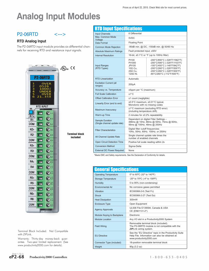
Analog Input Modules
P2-06RTD <--->RTD Analog InputThe P2-06RTD input module provides six differential chan-nels for receiving RTD and resistance input signals.
RTD Input SpecificationsInput Channels 6 DifferentialMax. Common Mode Voltage
5VDC
Data Format Floating Point
Common Mode Rejection -90dB min. @ DC, -150dB min. @ 50/60 Hz
Absolute Maximum Ratings Fault protected input, ±50V
Internal Resolution 16-bit, ±0.1°C or °F (up to 100Hz fi lter)
Input Ranges(RTD Types)
Pt100Pt1000JPt10010Ω Cu.25Ω Cu.120Ω Ni.
-200°C/850°C (-328°F/1562°F)-200°C/595°C (-328°F/1103°F)-100°C/450°C (-148°F/842°F)-200°C/260°C (-328°F/500°F)-200°C/260°C (-328°F/500°F)-80°C/260°C (-112°F/500°F)
RTD Linearization Automatic
Excitation Current (all ranges) 200μA
Accuracy vs. Temperature ±5ppm per °C (maximum)
Full Scale Calibration ±1°C
Offset Calibration Error ±1 count (negligible)
Linearity Error (end to end) ±0.5°C maximum, ±0.01°C typical,Monotonic with no missing codes
Maximum Inaccuracy ±1°C maximum (excluding RTD error)(including temperature drift)
Warm-up Time 2 minutes for ±0.2% repeatability
Sample Duration(Single channel update rate)
Dependent on digital Filter Settings –488ms @ 10Hz, 88ms @ 50Hz, 75ms @ 60Hz, 56ms @ 100Hz, 48ms @ 250Hz
Filter Characteristics Digital fi lter cutoff frequencies:10Hz, 50Hz, 60Hz, 100Hz, or 250Hz
All Channel Update Rate Single channel update rate times thenumber of enabled channels
Open Circuit Detection Time Positive full scale reading within 2s
Conversion Method Sigma-Delta
External DC Power Required None
°F
MV
1 OVER2 05263 1000 4 UNDER5 OVER6 21.35
°F
1 OVER2 05263 10004 UNDER4 UNDER5 OVER5 OVER5 OVER
MV
5 OVER6 21.35
General SpecificationsOperating Temperature 0º to 60ºC (32º to 140ºF)
Storage Temperature -20º to 70ºC (-4º to 158ºF)
Humidity 5 to 95% (non-condensing)
Environmental Air No corrosive gases permitted
Vibration IEC60068-2-6 (Test Fc)
Shock IEC60068-2-27 (Test Ea)
Heat Dissipation 300mW
Enclosure Type Open Equipment
Agency ApprovalsUL508 File E139594, Canada & USACE (EN61131-2*)
Module Keying to Backplane Electronic
Module Location Any I/O slot in a Productivity2000 System
Field WiringRemovable terminal block (included).The P2-06RTD module is not compatible with theZIPLink wiring system.
EU DirectiveSee the “EU Directive” topic in the Productivity Suite Help File. Information can also be obtained at:www.productivity2000.com
Connector Type (included) 18-position removable terminal block
Weight 90g (3.2 oz)
*Meets EMC and Safety requirements. See the Declaration of Conformity for details.
Terminal Block Included. Not Compatible with ZIPLink.
Warranty: Thirty-day money-back guar-antee. Two-year limited replacement. (See www.productivity2000.com for details).
ULC USR
Terminal block included
1 - 8 0 0 - 6 3 3 - 0 4 0 5eP2-68 Productivity2000 ControllersBook 1 (15.1)
Prices as of April 22, 2015. Check Web site for most current prices.

Analog Input Modules
P2-06RTD (cont’d)
RTD Input Circuits
2-wire RTD
R+
COM
Note: Connect two wires to one side of a 2-wire RTD.
R+
Resistance Input
R+
R-
COM
R+
R-
R-
3-wire RTD
COM
R-
COMNote: Leave 4th wire unattached as shown.
4-wire RTD
R1+
R1-
COM
R2+
COM
R3-
R3+
COM
R4+
R6-
COM
CH1 RTDINPUT
INTERNALMODULE CIRCUITRY
R4-
COM
R5+
COM
R6+
CH2 RTDINPUT
CH3 RTDINPUT
CH4 RTDINPUT
CH5 RTDINPUT
CH6 RTDINPUT
R2-
R5-
ANALOG CIRCUIT COMMON
12
34
56
78
910
1112
1813
1415
1617
Removable Terminal Block SpecificationsPart Number P2-RTB (included) P2-RTB-1
Number of positions 18 Screw Terminals 18 Spring Clamp Terminals
Wire Range
30 - 16 AWG (0.051 - 1.31 mm²)Solid / Stranded Conductor3/64 in. (1.2 mm) Insulation Maximum1/4 in (6 - 7 mm) Strip Length
28-16 AWG (0.081 - 1.31 mm²)Solid / Stranded Conductor3/64 in (1.2 mm) Insulation Maximum19/64 in (7 - 8 mm) Strip Length
Conductors “USE COPPER CONDUCTORS, 75ºC” or equivalent.Screw Driver Width 1/8 in (3.8 mm) Maximum
Screw Size M2 N/A
Screw Torque 2.5 lb·in (0.28 N·m) N/A
DiagnosticsModule Diagnostics Failure 1 bit per module
Module Not Ready 1 bit per module
Channel Burn-out (RTD only) 1 bit per channel
Under-range (RTD only) 1 bit per channel
Over-range 1 bit per channel
Resistance Input SpecificationsInternal Resolution
16 bit, .0015% of full scale range in ohms(up to 100Hz fi lter)
Resistance Input Ranges and CPU Resolution
0-10,000�, Resolution 1�0-6,250�, Resolution 0.1�0-3,125�, Resolution 0.1�0-1,562.5�, Resolution 0.1�0-781.25�, Resolution 0.1�0-390.625�, Resolution .01�0-195.3125�, Resolution .01�
Accuracy vs. Temperature ±25ppm per °C (maximum)Full Scale Calibration ± .02% of full scale rangeOffset Calibration Error ± .0015% of full scale range in ohms
Linearity Error (end to end)± .0015% of full scale range maximum at 25°C, Monotonic with no missing codes
Maximum Inaccuracy ± 0.10% of full scale range
R+
COM
R-
Notes: For maximum accuracy follow these guidelines.1. For 2-wire RTD, attach third wire to module common.2. R+, R-, and COM wires to an RTD must be equal length and type. Refer to RTD manufacturer’s
recommendations.3. Do not use cable shield as sensing wire.4. When applicable, connect shield to RTD common only, otherwise connect to module common
only. Do not connect shield at both ends.5. For maximum accuracy jumper unused inputs to common
w w w . a u t o m a t i o n d i r e c t . c o m / p r o d u c t i v i t y 2 0 0 0 Productivity2000 Controllers eP2-69Book 1 (15.1)
Prices as of April 22, 2015. Check Web site for most current prices.
CompanyInformation
Control SystemsOverview
CLICK PLC
Do-More PLCs Overview
Do-More H2PLC
Do-More T1HPLC
DirectLOGICPLCs Overview
DirectLOGICDL05/06
DirectLOGICDL105
DirectLOGICDL205
DirectLOGICDL305
DirectLOGICDL405
ProductivityControllerOverview
Productivity3000
Productivity2000
UniversalField I/O
Software
C-MoreHMI
C-More MicroHMI
ViewMarqIndustrialMarquees
Other HMI
Communications
AppendixBook 1
Terms andConditions

I/O ModulesA variety of discrete, analog and specialty I/O modules are available for use in a P2000 System. Specifications for each module are on the following pages.
A filler module is available for unused I/O module slots (part number P2-FILL).
Productivity2000 Discrete Output Modules
Part Number Number of Outputs Description Price
P2-08TD1P 8 Sinking Protected Output <--->P2-08TD2P 8 Sourcing Protected Output <--->P2-16TD1P 16 Sinking Protected Output <--->P2-16TD2P 16 Sourcing Protected Output <--->P2-16TA 16 AC Output <--->P2-08TRS 8 Isolated Relay Output <--->P2-16TR 16 Relay Output <--->
Productivity2000 Analog Output Modules
Part Number Number of Channels Description Price
P2-04DA 4 Analog Output <--->P2-08DA-1 8 Analog Output (Current) <--->P2-08DA-2 8 Analog Output (Voltage) <--->P2-16DA-1 16 Analog Output (Current) <--->
P2-16DA-2 16 Analog Output (Voltage) <--->
Productivity2000 Analog Input/Output Modules
Part Number Number of Channels Description Price
P2-8AD4DA-1 8/4 Analog Input/Output (Current) <--->P2-8AD4DA-2 8/4 Analog Input/Output (Voltage) <--->
Module Installation Procedure
Step Three: Attach field wiring using removable terminal block or ZIPLink wiring system.
Step One: Align module catch with base slot and rotate module into con-nector.
WARNING: Explosion hazard – Do not connect or disconnect connec-tors or operate switches while circuit is live unless the area is known to be non-hazardous. Do not hot-swap modules unless the area is known to be non-hazardous.
Discrete Input Modules
Discrete Output Modules
Specialty Modules
Analog I/O Modules
Productivity2000 Discrete Input Modules
Part Number Number of Inputs Description Price
P2-08SIM 8 Input Simulator Module <--->P2-08NE3 8 Sinking/Sourcing AC/DC Input <--->P2-16NA 16 AC Input <--->P2-16NE3 16 Sinking/Sourcing AC/DC Input <--->
Productivity2000 Specialty Modules
Part Number Number of Channels Description Price
P2-HSI* 2 High-Speed Input <--->P2-HSO* 2 High-Speed Output <--->P2-SCM 4 ports Serial Communications Module <--->*ZIPLink required.
Productivity2000 Analog Input Modules
Part Number Number of Channels Description Price
P2-04AD 4 Analog Input <--->P2-08AD-1 8 Analog Input (Current) <--->P2-08AD-2 8 Analog Input (Voltage) <--->P2-16AD-1 16 Analog Input (Current) <--->
P2-16AD-2 16 Analog Input (Voltage) <--->
P2-06RTD 6 Analog RTD Input <--->P2-08THM 8 Analog Thermocouple Input <--->
Locked Unlocked
1 Alignwith slot
2 rotateto seatedposition
WIRE STRIPLENGTHWIRE STRIPLENGTH
Step Two: Pull top lock-ing tab toward module face. Click indicates lock is engaged.
WARNING: Do not apply field power until the following steps are completed. See hot-swapping procedure for exceptions.
1 - 8 0 0 - 6 3 3 - 0 4 0 5eP2-36 Productivity2000 ControllersBook 1 (15.1)
Prices as of April 22, 2015. Check Web site for most current prices.